Sick RFI3411503S04 RFID (Radio frequency interrogator) User Manual Users manual
Sick AG RFID (Radio frequency interrogator) Users manual
Sick >
Users manual

Annex No.5
Page 1 of 46
Functional description
RFI341-1503S04

Preliminary
8012640/2008-03-10 © SICK AG • Division Auto Ident • Germany • All rights reserved
OPERATING INSTRUCTIONS
RFI341-1503
Radio Frequency Interrogator

RFI341 Radio Frequency Interrogator
2 SICK AG − Division Auto Ident - Germany - All rights reserved 8012640/2008-03-10
Software Versions
Software Version
DSP Firmware V1.2.10
ARM7 Firmware V0.24
Copyright
Copyright © 2007
SICK AG Waldkirch
Auto Ident, Reute Plant
Nimburger Strasse 11
79276 Reute
Germany
Trademarks
WindowsTM is a registered trademark or trademark of the Microsoft Corporation in
the USA and other countries.
Latest Manual Version
For the latest version of this manual (PDF), see www.sick.com.
Software Versions

RFI341 Radio Frequency Interrogator
3 SICK AG − Division Auto Ident - Germany - All rights reserved 8012640/2008-03-10
Contents
SOFTWARE VERSIONS 2
ABOUT THIS DOCUMENT 6
1.1 Purpose 6
1.2 Target Application Group 6
1.3 Symbols used 6
SAFETY INFORMATION 7
2.1 Authorized Personnel 7
2.1.1 Assembly and maintenance 7
2.1.2 Electrical Connection and Replacement 7
2.1.3 Start-up, Operation and Configuration 7
2.1.4 Intended Use 8
2.2 General Safety Instructions and Protective Measures 9
2.3 Quick Stop and Restart 9
2.4 Environmental Conditions 9
2.4.1 Power Requirements 9
2.4.2 Disposal after Final Placing out of Operation 9
PRODUCT DESCRIPTION 10
3.1 Design 10
3.1.1 Scope of Delivery 10
3.1.2 Variants 11
3.1.3 System Requirements 11
3.1.4 Product Features and Functions (Overview) 12
3.1.5 Details (Basic version) 13
3.1.6 Details (M12 connectivity version) 14
3.1.7 Details (Profibus stainless steel version) 15
Inside View (main board, profibus CMF gateway, Profibus connection) 15
3.1.7 Details (FCC Version) 16
3.1.8 View of Details (Splitter) 18
3.1.9 View of Details (Mutliplexer) 18
3.2 Functional Description of the device 19
3.3 Operating Elements and Indicators 20
3.3.1 Operating Elements 20
3.3.2 Function of the LEDs 21
4. ASSEMBLY 22
4.1 Overview about the Assembly Steps 22
4.2 Preparation for Installation 22
4.2.1 Component required 22
4.2.2 Accessories 22
Content

RFI341 Radio Frequency Interrogator
4 SICK AG − Division Auto Ident - Germany - All rights reserved 8012640/2008-03-10
4.2.3 Selecting the Installation Location 22
4.2.4 Brackets 23
5. ELECTRICAL INSTALLATION 24
5.1 Overview of the Installation Steps 24
5.2 Electrical Connections (basic version) 24
5.3 Electrical Connections (M12 connectivity version) 25
5.4 Preparations for Electrical Installation 25
5.4.1 Requirements for the RS-232 HOST interface 25
5.4.2 Requirements for the Profi-Bus interface 25
5.4.3 Main Power supply 26
5.4.4 Connect the RS-232 interface 26
5.4.5 Connecting the “Input 1” Switching Input 27
5.4.6 Connecting the Switching Output 28
5.4.7 Ethernet 28
5.5 Performing Electrical Installation (Basic-Version) 29
5.5.1 Overview of the Connection Procedure 29
5.6 Performing Electrical Installation (Profibus-Version) 29
5.6.1 Overview of the Connection Procedure 29
5.6.2 Connect the earth ground 29
5.6.3 Connect the RS232 Interface 30
5.6.4 Connect the Profi-Bus Interface 30
OPERATION 31
6.1 Overview of the Start-up Steps 31
6.2 Factory Default Settings 31
6.3 Configuration (Parameterisation) 32
6.3.1 Antenna Output Power 32
6.3.2 RS232 Data Interface 32
6.3.3 Oscillator Switch off delay 33
6.3.4 Read after Write Verify 33
6.3.5 HF Reset for Inventory Commands 33
6.4 ISO/IEC 15693 settings 34
7. MAINTANANCE 35
7.1 Maintenance 35
7.2 Disposal 35
8. TROUBLESHOOTING 36
8.1 Installation errors 36
8.2 Electrical Connection Errors 36
8.3 Parameterisation Errors 36

RFI341 Radio Frequency Interrogator
5 SICK AG − Division Auto Ident - Germany - All rights reserved 8012640/2008-03-10
9. TECHNICAL DATA 37
9.1 RFI341-1503 37
9.2 Dimensional Drawing 38
10. APPENDIX 39
10.1 Accessories 39
10.2 Glossary, Standard Basics, and Abbreviations 39
10.3 ISO/IEC 15693 – ISO/IEC 18000-3 Mode 1 Basics 41
RFI341 Radio Frequency Interrogator
6 SICK AG − Division Auto Ident - Germany - All rights reserved 8012640/2008-03-10
1. About this Document
1.1 Purpose
This document provides information on placing the RFI341 Interrogator.
This document contains information about:
• Mounting and electrical installation
• Start-up
• Use and configuration
• Maintenance
• Special applications and practices
1.2 Target Application Group
The target groups for this user guide are:
• Operating electricians
• Technicians and engineers
1.3 Symbols used
Some of the information in this document is especially marked so that it can
be accessed quickly.
Warning!
Warnings are provided to prevent injury to operating personnel or serious
damage to the RFID Interrogator.
→ Always read warnings carefully and observe them at all times.
Notes provide information on special features or characteristics.
Explanations provide background information on technical aspects.
Recommendations provide advice on how to carry out a task more effectively
This symbol refers to additional technical documentation.
Note
Explanation
Recommendation
About this Document

RFI341 Radio Frequency Interrogator
7 SICK AG − Division Auto Ident - Germany - All rights reserved 8012640/2008-03-10
2. Safety Information
2.1 Authorized Personnel
• For the RFI341 to function correctly and safely, it must be installed
and operated by sufficiently qualified personnel.
• The end user must be supplied with the operating instructions.
• The end user must be provided with expert training and is advised to
read the operating instructions.
• The following qualifications are required for the various tasks
involved.
2.1.1 Assembly and maintenance
• Practical basic technical training
• Knowledge of the standard guidelines relating to safety in the
workplace
2.1.2 Electrical Connection and Replacement
Practical training in electrical technology
• Knowledge of the standard safety guidelines relating to electrical
technology
• Knowledge regarding the operation of the devices in the relevant
application (e.g. conveyor belt)
2.1.3 Start-up, Operation and Configuration
Knowledge regarding the operation of the devices in the relevant application
(e.g. conveyor belt)
• Knowledge of the software and hardware environment of the relevant
Application
• Basic understanding of data transfer methods
• Basic understanding of RFID technology
Safety information

RFI341 Radio Frequency Interrogator
8 SICK AG − Division Auto Ident - Germany - All rights reserved 8012640/2008-03-10
2.1.4 Intended Use
The RFI341 is designed to detect and decode 13.56 MHz, ISO 15693
compliant RFID transponder signals. It is used together with antennas
installed in a reading station and reads from and writes to RFID transponders
on objects positioned, e.g., on a conveyor belt.
The RFI341 enables the bi-directional communication with a host for, e.g.,
further processing.
Any warranty claims against SICK AG will be rendered invalid if the device is
used for any other purpose or if changes are made to the device including
changes made during the installation and electrical connection procedures.
Safety information
RFI341 Radio Frequency Interrogator
9 SICK AG − Division Auto Ident - Germany - All rights reserved 8012640/2008-03-10
2.2 General Safety Instructions and Protective Measures
Read carefully the general safety instructions and observe them at all times.
This also applies to the warnings provided for the activities described in each
chapter of this document.
Risk of injury by electrical current!
The power supply is connected to the main voltages 24V DC.
→ When working with electrical equipment, always follow the relevant
safety instructions.
2.3 Quick Stop and Restart
Switching off the power supply of the RFI341 can result in loss of the
following:
• The specific application parameter set, if it was set only temporarily
• The last reading in the result buffer
2.4 Environmental Conditions
The RFI341 is designed to cause minimum impact to the environment.
2.4.1 Power Requirements
The RFI341 has a maximum power consumption of 50W.
2.4.2 Disposal after Final Placing out of Operation
Always dispose of unusable or irreparable devices in a manner that is not
harmful to the environment and in accordance with the applicable national
waste disposal regulations. The RFI341 can be separated into recyclable
secondary raw materials and special category waste (electronic scrap).
At present, SICK does not accept the return of unusable or irreparable
devices.
Safety information

RFI341 Radio Frequency Interrogator
10 SICK AG − Division Auto Ident - Germany - All rights reserved 8012640/2008-03-10
3. Product Description
THE RFI341 RFID System is used for wireless identification of a variety of
objects. It works at a frequency of 13.56 MHz and reads passive ISO/IEC
15693 tags. For a working RFID system, antennas and transponders as well
as a host computer are required in addition to the product itself.
3.1 Design
3.1.1 Scope of Delivery
In the packaging, the RFI3411 is supplied with:
- 3-core RS 232 data cable (9-pin Sub D socket, open end), length 1.5 m
- An information sheet with terminal diagram and quick-start instructions
- CD-ROM with:
RFI341 PC Software for WindowsTM
RFI341 Telegram Listing
RFI341 Operating instructions
RFA3xx Antenna Operation Instructions
The latest versions of all applicable publications/programs on the CD-ROM
can be also downloaded from www.sick.com
Chapter 10.1, “Accessories” provides an overview of the available
installation accessories and standard antenna types as well as measurement
equipment and sensors for reading pulse generation.
Note
Product Description
RFI341 Radio Frequency Interrogator
11 SICK AG − Division Auto Ident - Germany - All rights reserved 8012640/2008-03-10
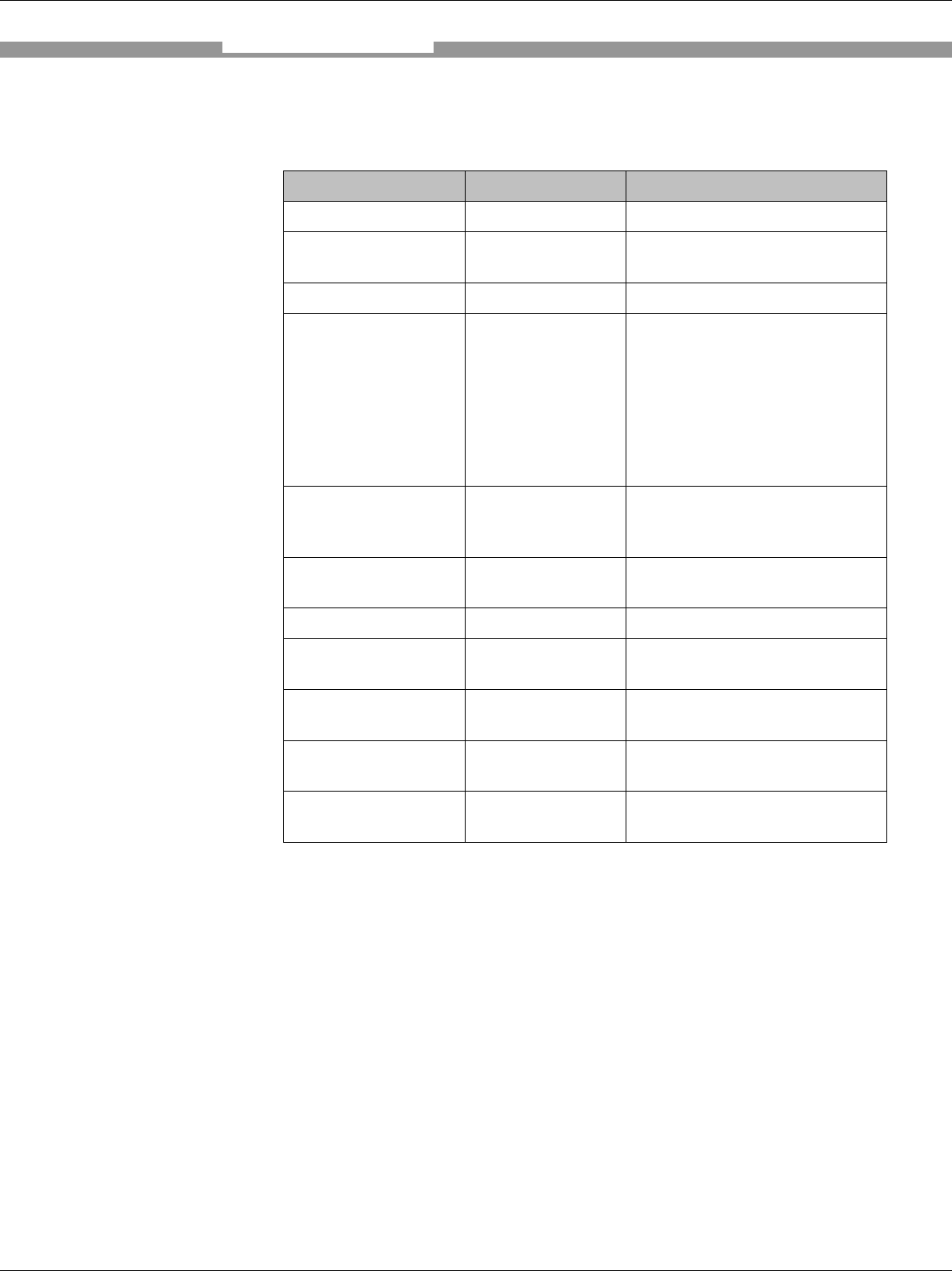
3.1.2 Variants
Type Order No. Description
RFI341-1503 1043330 RFI341 13,56MHz basic
RFI341-1503S01 1043981 RFI341; Stainless steel with
integrated Profibus
RFI341-1503S02 1044537 RFI341 with M12 connectivity
RFI341-1503S04 1045449 RFI341 his device complies
with Part 15 of the FCC Rules.
Operation is subject to the
following two conditions:
Additional Filter to be used as
shown in this spec. In case Mux
is used the FCC Version need
to be used.
Splitter 6036000 One (4W) to two (2W) antenna
splitter (passive) ; not for use
with ProfiBus-Version
Multiplexer 6036002 One (4W) to up to 4 Antenna
(each 4W) mulitplexer
Multiplexer FCC 6037325 FCC Version of the mulitplexer
Filter FCC 6037324 Filter to be used in case FCC
Part 15 need to be addressed
Antenna adapter 2046653 Bulgin to BNC antenna
connector converter.
Interface cable
RS232 tbd M12 to RS232 interface cable
Interface cable Mux
Control 6035859 Control interface between
RFI341 and external multiplexer
3.1.3 System Requirements
The following are required to start up and operate the RFI341:
1. 24V DC mains power source
2. Using external clock pulse (start/stop interval) e.g. via the sensor inputs,
suitable reading pulse sensors for signalling the presence of an object or
the end of a reading/writing interval, e.g., a photoelectric reflex switch are
required.
3. A higher level computer (host system) with a Ethernet or RS232 to run
the PC Demo Software on a PC (Windows XP)
4. A SICK 13.56 MHz antenna, Type RFA3xx
Product Description

RFI341 Radio Frequency Interrogator
12 SICK AG − Division Auto Ident - Germany - All rights reserved 8012640/2008-03-10
3.1.4 Product Features and Functions (Overview)
High Performance RFID Interrogator
• 13.56 MHz carrier frequency
• Compliant with the ISO 15693 standard
• High RF transmit output power 4 W
• Reading distance of up to 1.2 m (depended on the used antenna
transponder setup)
• RS232 and Ethernet interface (Profibus for the PB version)
• SWR (standing wave ratio) diagnostic
Safety and User Friendly Features
• Robust, compact industrial housing (variant with stainless steel
housing), IP 65 (IP66 for the stainless steel version)
• Capable of future improvements thanks to firmware update via serial
data interface
• Two driving outputs for actuator management
Easy Operation/Configuration
• Provided with RFI341 PC Demo Software for Windows
• Alternatively controllable with simple command strings
• LED for data indication
Product Description
RFI341 Radio Frequency Interrogator
13 SICK AG − Division Auto Ident - Germany - All rights reserved 8012640/2008-03-10
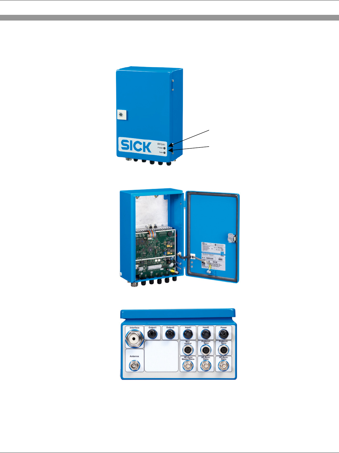
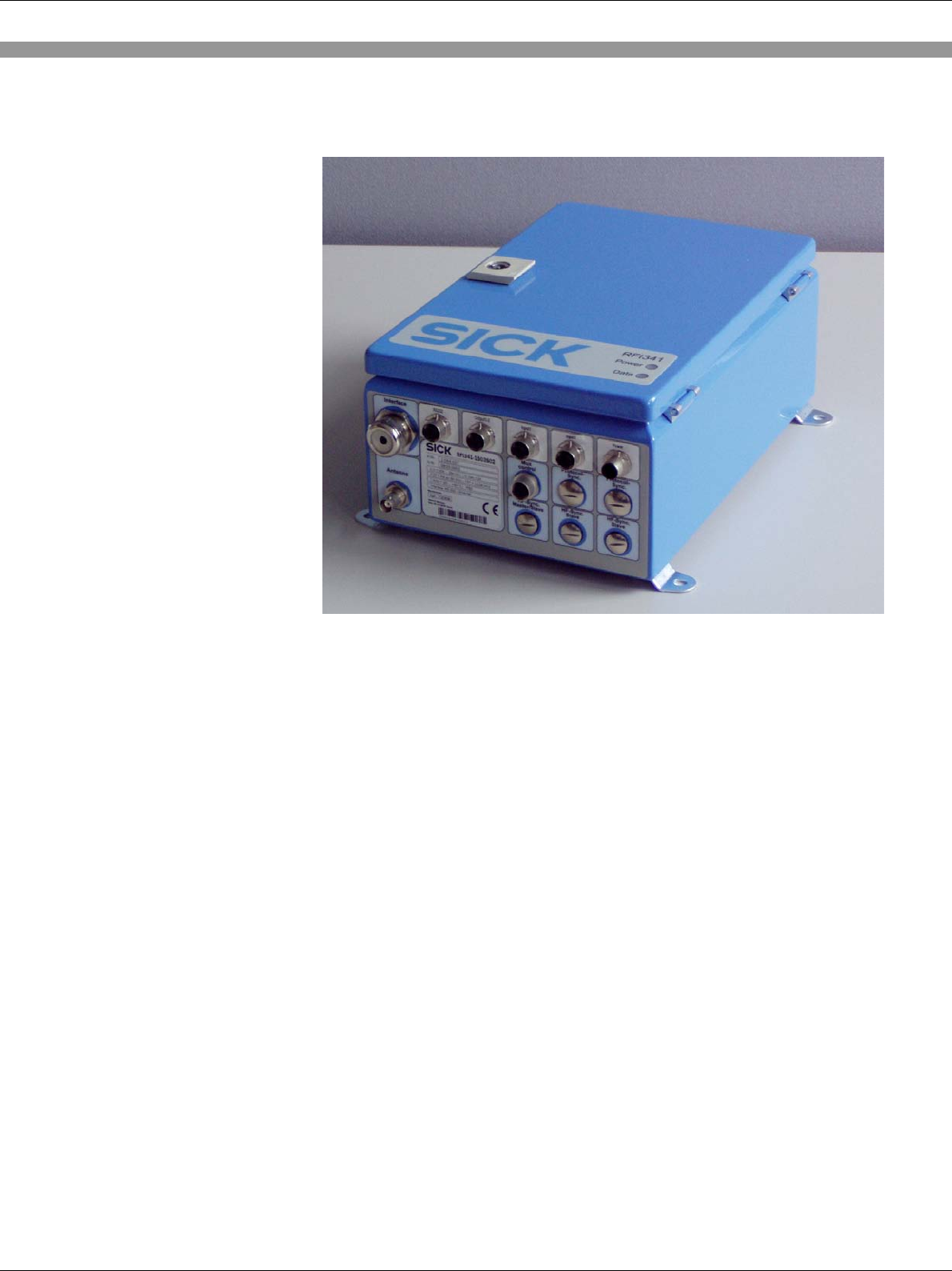
3.1.5 Details (Basic version)
Power LED – indicate
that the DC
p
ower is on
Data LED – indicate that
Ta
g
data will be send
RFI341 Radio Frequency Interrogator
14 SICK AG − Division Auto Ident - Germany - All rights reserved 8012640/2008-03-10
3.1.6 Details (M12 connectivity version)
RFI341 Radio Frequency Interrogator
15 SICK AG − Division Auto Ident - Germany - All rights reserved 8012640/2008-03-10
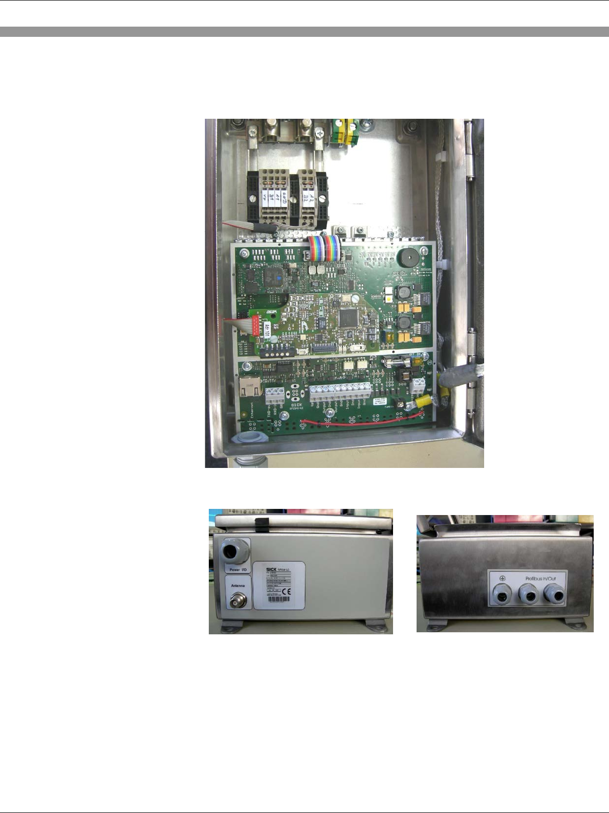
3.1.7 Details (Profibus stainless steel version)
Inside View (main board, profibus CMF gateway, Profibus connection)
RFI341 Radio Frequency Interrogator
16 SICK AG − Division Auto Ident - Germany - All rights reserved 8012640/2008-03-10
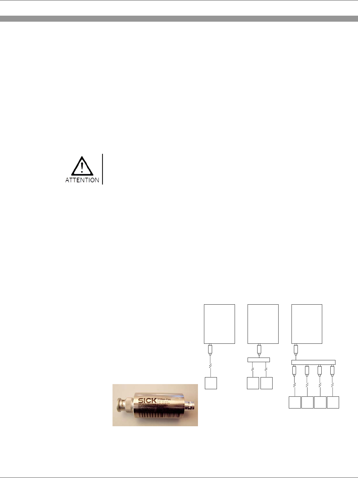
3.1.7 Details (FCC Version)
This device complies with Part 15 of the FCC Rules. Operation is subject
to the following two conditions:
(1) This device may not cause harmful interference, and
(2) this device must accept any interference received, including
interference that may cause undesired operation.
Any changes or modifications not expressly approved by SICK AG could
void the user's authority to operate this equipment.
To address the FCC requirements the power supply cable as well as the
interface cable must be a shielded version. It need to be ensured, that
the shield is direct connected to the PG glant.
The FCC device is only addressing the FCC rules with the antenna
RFA331-1020 and RFA341-3520.
Usage of additional Filters required to address FCC rules. The number of
Filters required depends on the usage of external components/antennas:
1.) One antenna used direct at the antenna output of the RFI341 require
the usage of an FCC Filter at the RFI341 antenna output.
2.) If the splitter is used a Filter is required at the RFI341 antenna output
3.) If a Multiplexer is used a Filter need to be used at the RFI341
Antenna output and at each RF outputs of the Multiplexer.
RFI341-
1503S04
ANT
Filter
RFI341-
1503S04
ANT
Splitter
ANT
RFI341-
1503S04
ANT
Multiplexer
ANT
Filter
Filter
Filter
ANT ANT
Filter
Filter
Standard
one antenna Splitter
two antenna Multiplexer
1-4 antenna
Filter
RFI341 Radio Frequency Interrogator
17 SICK AG − Division Auto Ident - Germany - All rights reserved 8012640/2008-03-10
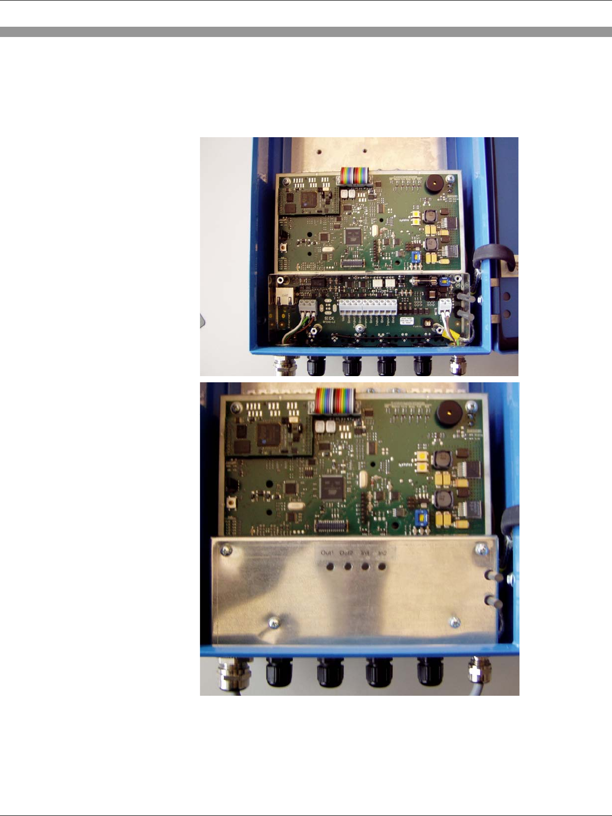
Inside view RFI341-1503S04
The FCC Version require a shielded power supply cable.
Note
RFI341 Radio Frequency Interrogator
18 SICK AG − Division Auto Ident - Germany - All rights reserved 8012640/2008-03-10
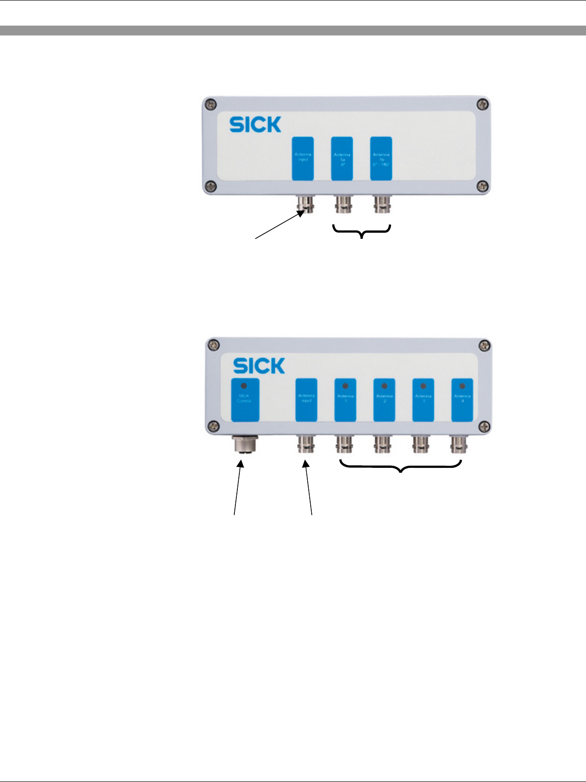
3.1.8 View of Details (Splitter)
3.1.9 View of Details (Mutliplexer)
Mux Control interface –
must be connected to the
RFI Mux Control output
Antenna Mux input –
must be connected to the
RFI341 antenna output
Mux – Antenna output 1 to 4
Antenna input – must be connected
to RFI341 antenna output Antenna output – each
0
,
5 x Tx in
p
ut
p
owe
r

RFI341 Radio Frequency Interrogator
19 SICK AG − Division Auto Ident - Germany - All rights reserved 8012640/2008-03-10
3.2 Functional Description of the device
The device operates according the reader/interrogator “talks first” (ITF)
method as defined in the ISO/IEC 15693 Standard. Each transponder in
the field remains silent until a request is received. The interrogator can
identify simultaneously a number of tags present in the antenna field. The
interrogator can write data to and read data from the transponders.
Transponders can be addressed by e.g. using the factory programmed,
unique read only number (64 bit length). If the data in the user memory of
the tag are not write protected, the read/write feature enables the
rewriting of the data stored in this memory.
The RFI341 is controlled by the data interface. The commands are
described in the document “Telegram Listing RFI341” which enables the
use of the features defined in ISO/IEC 15693. Additional commands
support the use of sensor inputs and/or actuators. After configuration the
device could either work in a mode where the host in controlling the unit
or in trigger mode. Configuration in trigger mode means: The device is
waiting for a start condition to start reading automatically. Reading results
will be transmitted directly or with closing the read window. If the device
is running in background mode only a valid escape sequence will
terminate this and brings the device back in command mode (see also
telegram listing).
To start a reading process, when an object with a transponder is in the
field, the RFI341 must be clocked by one of the following:
• A command sequence via the data interface
• The execution (based on a suitable trigger) of a previously
defined background command
If a transponder is detected, the relevant data can be send via the data
interface to the host. The “Data LED” indicates the presence of tag data.
Product Description

RFI341 Radio Frequency Interrogator
20 SICK AG − Division Auto Ident - Germany - All rights reserved 8012640/2008-03-10
3.3 Operating Elements and Indicators
3.3.1 Operating Elements
The RFI341 is operated and configured via the data interface (host) using
the PC Demo Software (RS232), or command strings send via the host
interface. A variety of parameterisation options allows for the adaptation
of the device to a wide range of applications.
The following can be set:
ISO Settings including:
• Modulation depth
• Tag modulation type
• Tag data rate
• AFI (Application Field Identifier)
• DSFID (Data Storage Field Identifier)
RFI341 Settings Including:
• RF output power
• Communication parameters for the interface
• Switching on of the RF field (test)
• Port time-out value
Detailed information could be found in the telegram listing
Product Description
RFI341 Radio Frequency Interrogator
21 SICK AG − Division Auto Ident - Germany - All rights reserved 8012640/2008-03-10
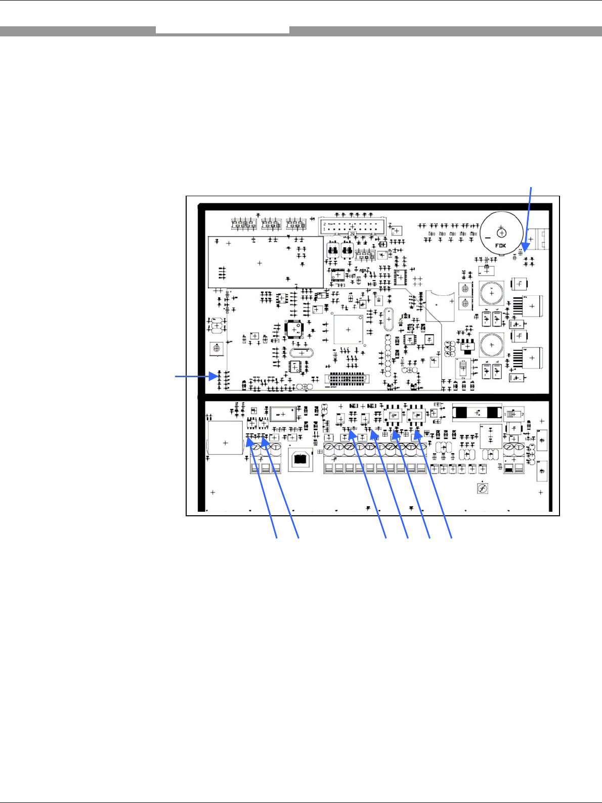
3.3.2 Function of the LEDs
The RFI341 does have several LEDs on the main PCB board. A few of
them could be useful for device service functions.
Closed to the terminals there is an indicator for:
• RXT and TXD (Data will be sent from and to Host)
• Input and output LED’s indicate the status of the IN/OUT ports
• LED bar indicates the SWR value if measurement manually
activated
Product Description
Out-1 Out-2 In-1 In-2LED: TXD RXD
Power LED‘s
LED’s for
SWR
measurement

RFI341 Radio Frequency Interrogator
22 SICK AG − Division Auto Ident - Germany - All rights reserved 8012640/2008-03-10
4. Assembly
4.1 Overview about the Assembly Steps
• First, select the installation location for the RFA3xx antenna
• Select the installation location for the RFI341
• If used, select the installation location for the sensor(s)
4.2 Preparation for Installation
4.2.1 Component required
• RFI341
• RFA3xx (antenna)
• Antenna connector converter
• Probably a splitter or mulitplexer
4.2.2 Accessories
• Screws
• Reading pulse sensor (if used)
• Warning labels (if required, not included with the RFI341)
4.2.3 Selecting the Installation Location
For the selection of the installation location, the distance between the RFI341
and the RFA3xx antennas as well as the distance between the RFI341 and
the host are important.
Assembly
RFI341 Radio Frequency Interrogator
23 SICK AG − Division Auto Ident - Germany - All rights reserved 8012640/2008-03-10
Distance Between the RFI341 and the Host
The RFI341 can be installed with a maximum data cable length depended on
the used interface and the chosen data rate (see chapter 5.4.1)
Distance Between the RFI341 and the RFA321 Antennas
The RFI341 can be installed at a maximum distance given by the antenna
cable length. Increasing the cable length will have an impact to the operating
performance.
4.2.4 Brackets
The housing can be mounted by using the pre-assembled mounting brackets
which are pre-mounted. The position of the brackets can not be changed by
the customer. The basic do have the brackets to the left and right whereas
the Profibus version does have them on the top and bottom.
Assembly
RFI341 Radio Frequency Interrogator
24 SICK AG − Division Auto Ident - Germany - All rights reserved 8012640/2008-03-10
5. Electrical Installation
5.1 Overview of the Installation Steps
• Connect the RFI341 with the Antenna
• Connect the sensors to the RFI341 inputs (if used)
• Connect the actuators to the RFI341 outputs (if used)
• Connect the PC or Profibus data interface of the RFI341
• Connect the power supply to the RFI341
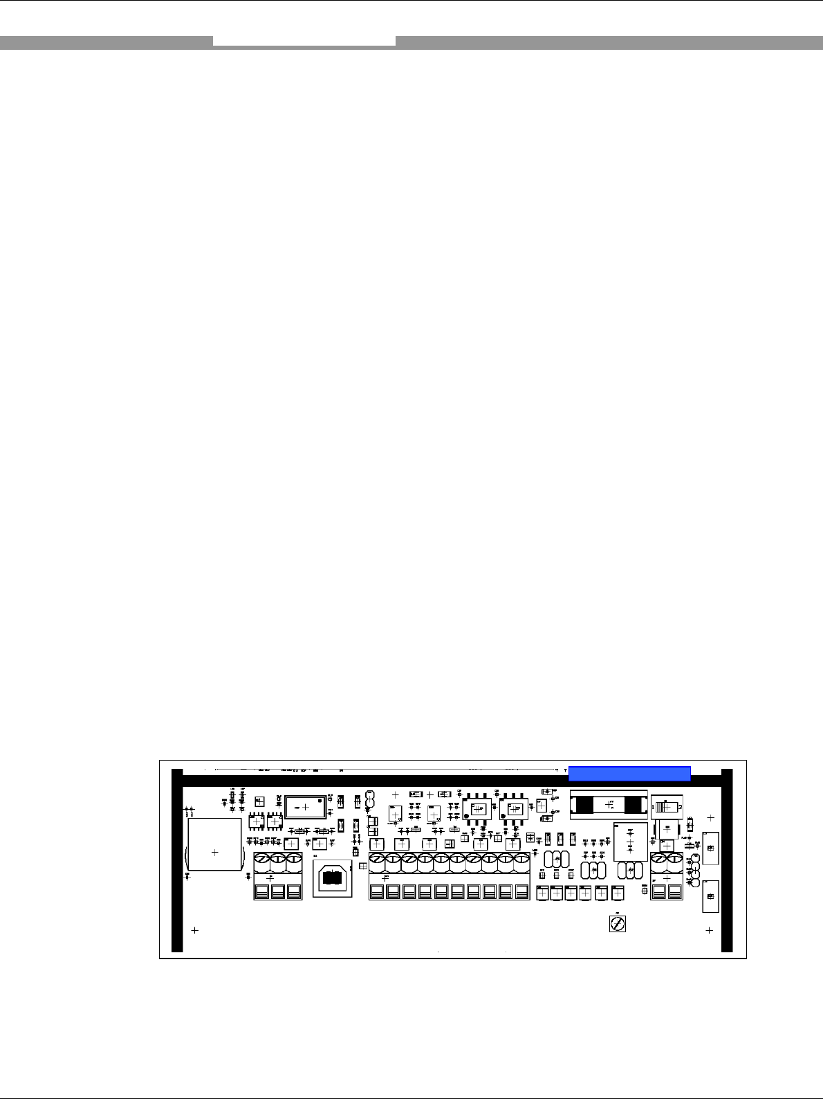
5.2 Electrical Connections (basic version)
The electrical connections of the RFI341 consist of:
• Socket for the RFA3xx antenna connection
• Mux-Control interface
• PG’s for cable connections for:
o Two galvanic separated switching input terminals with each a
separate reference
o Two switching outputs - 24 V DC in reference
o Three terminals for the RS 232 data interface, Ethernet RJ45
plug
o Two terminals for the main supply (24V DC) and Terminals for
grounding (PE)
See 5.4.5 / 5.4.6 for In- Output connections
Electrical Installation
RXD In
TXD out
GND
VS
GND
Out 1
GND
OUT 2
GND
IN 1
GND 1
IN 2
GND 2
+24V in
GND
Ethernet
FUSE 2A/T Power switch
RFI341 Radio Frequency Interrogator
25 SICK AG − Division Auto Ident - Germany - All rights reserved 8012640/2008-03-10
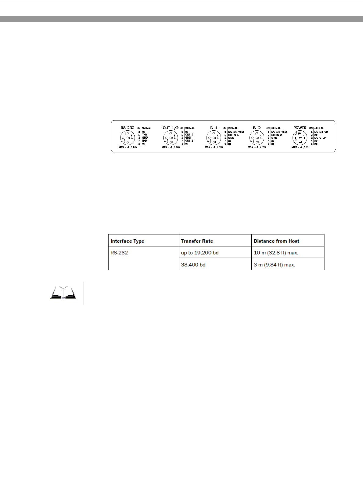
5.3 Electrical Connections (M12 connectivity version)
The M12 Connectivity Version consist out of one PG plug for e.g. Ethernet
and M12 plugs for power, RS232, Output and 2 for the Trigger Input. The
individual pinning could be found on a sticker that is placed inside the device
door.
5.4 Preparations for Electrical Installation
5.4.1 Requirements for the RS-232 HOST interface
The host interface can be operated as a RS 232 data interface. The
maximum cable lengths are a function of the selected data transfer rate:
To prevent interference, do not lay the cable parallel to the mains supply and
motor cables over long distances, e.g., in cable ducts.
5.4.2 Requirements for the Profi-Bus interface
The Bus termination is realised with 3 resistors mounted at the terminals. If a
device is not the last station in a Profi-Bus network those resistors have to be
removed. The shielding need to be fixed with the available shielding
brackets at the PG glands.
Note
RFI341 Radio Frequency Interrogator
26 SICK AG − Division Auto Ident - Germany - All rights reserved 8012640/2008-03-10
5.4.3 Main Power supply
The main power supply is 24V DC with a max input current of less than 2
Ampere (<50W). The power cable need to be shielded if the length extend
3m. The Shield need to be connected with the “Function earth”.
Power-up Delay
After the RFI341 is powered, the device will do an internal diagnostic. After
the diagnostic is finished the interrogator sends the start-up message or will
execute the background mode. This start-up time can be within a window of
less than 3 seconds. Refer to the document “Telegram Listing RFI341” for
details.
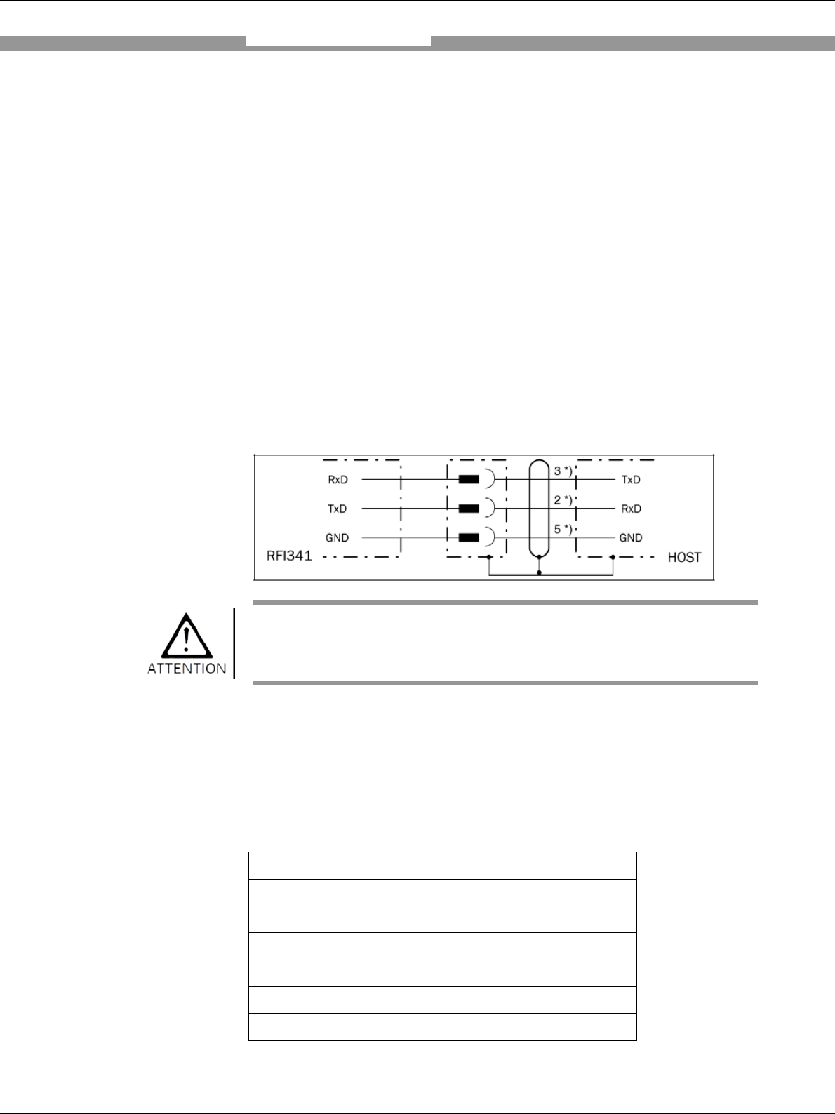
5.4.4 Connect the RS-232 interface
Risk of damage to the interface module!
Electronic components in the RFI341 can be damaged if the host is
connected incorrectly.
• Connect the host as shown in the figure above.
• Check the connections carefully before switching on the RFI341.
• Connect the host interface to the RFI341 using shielded cable (EMC
requirement). Ensure that the maximum cable length is not exceeded.
Parameter Value
Interface model RS 232
Data transfer rate 9600 bd (factory setting)
Start bit 1
Data bits 8
Stop bits 1
Parity No parity
Protocol SICK STX/ETX
Electrical Installation
RFI341 Radio Frequency Interrogator
27 SICK AG − Division Auto Ident - Germany - All rights reserved 8012640/2008-03-10
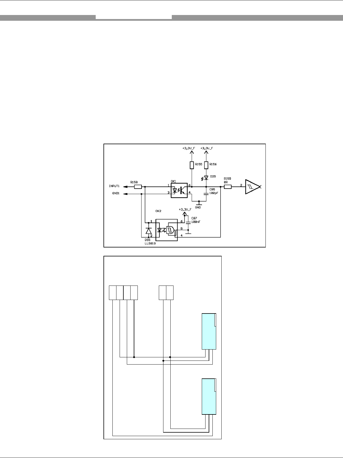
5.4.5 Connecting the “Input 1” Switching Input
If a reading procedure of the RFI341 shall be triggered by an external
sensor, then the reading pulse sensor must be connected, e.g., to the Input 1
switching input. The triggering feature is set by the background function as
described in the document “Telegram Listing RFI341”. The GND1 is
galvanically separated. Therefore the reference for the Input 1 level must be
provided by the customer. OK1 not assembled.
Electrical Installation
Input 1
Gnd 1
Input 2
Gnd 2
+ 24V
GND
Scematic
External Sensor 1
External Sensor 2
Power supply
Switching Level
Imax,
U min,
U max
See 9.1 1
GND1 ≠ GND2
RFI341 Radio Frequency Interrogator
28 SICK AG − Division Auto Ident - Germany - All rights reserved 8012640/2008-03-10
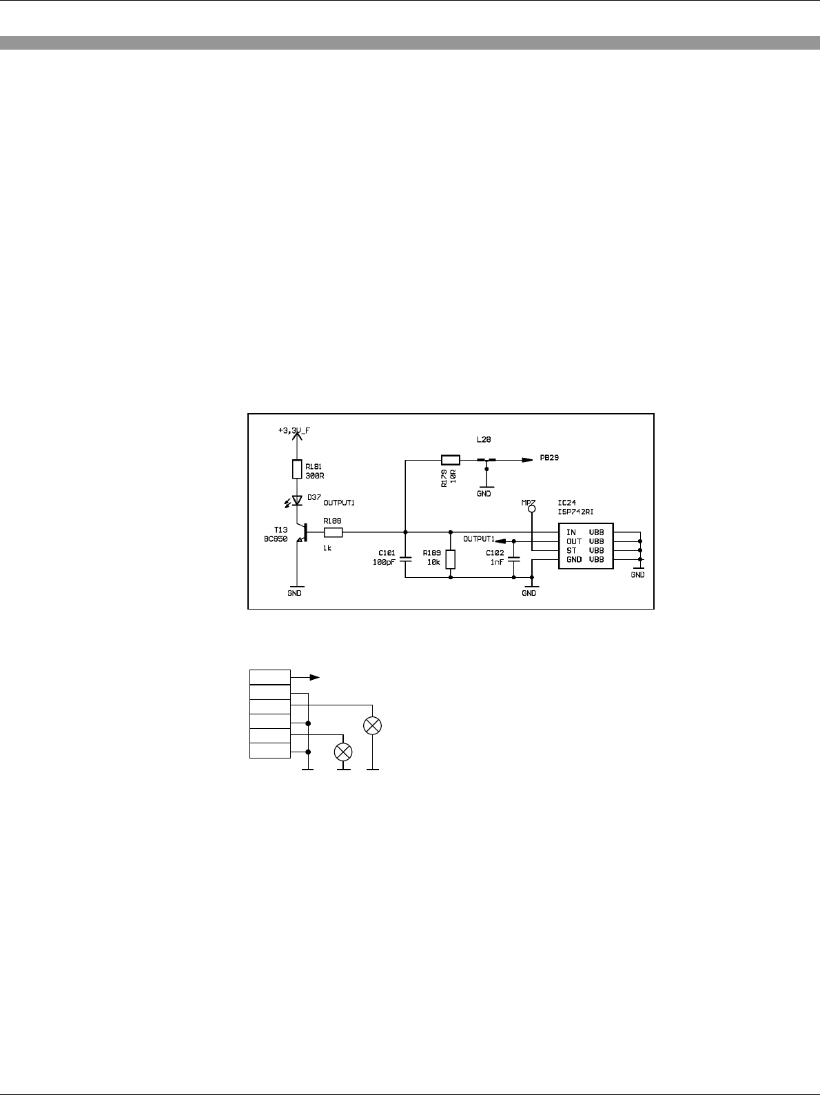
5.4.6 Connecting the Switching Output
The two switching outputs are completely user defined and controlled by
special command strings as described in the document “Telegram Listing
RFI341”. The maximum load current is 400 mA. The outputs are driven with
supply power (24V DC norminal). The output drivers are powered with the
DC input voltage of nominal 24V DC and with the Dc power supply
reference. There is a direct connection between VS0 clamp to 24V DC clamp
and from Gnd0 to GND. Optional the output driver could be driven with an
external power source. Please contact the application team for further
information.
5.4.7 Ethernet
By default the IP address will be organised by the DHCP server (dynamic mode). If
it is intended to use the device in static-IP-address mode the IP address and Subnet
Mask must be programmed before according to the used sub-net. For this please use
the available parameterisation software or the related STX/ETX commands as
described in the telegram-listing.
In Stand-Alone use with a Laptop an cross cable is required and the static IP address
must be used. In standard Network configuration a standard patch cable is required.
Scematic
VS
GND
Out 1
GND
Out 2
GND
Supply Output
Output Level see 9.1
Remark: GND1 (In1) ≠GND2 (In2) ≠ GND (Out1/2)

RFI341 Radio Frequency Interrogator
29 SICK AG − Division Auto Ident - Germany - All rights reserved 8012640/2008-03-10
5.5 Performing Electrical Installation (Basic-Version)
5.5.1 Overview of the Connection Procedure
• Connect the earth grounding
• Connect the RS-232 data interface or the Ethernet Interface
• Connect the switching inputs “Input 1 and 2”, if necessary
• Connect the switching outputs “Output 1 and 2”, if necessary
• Connect the splitter to the RFI341 if required
• Connect the multiplexer to the device using the Mux-control interface, if
required
• Connect the RFA3xx antenna(s)
• Connect the main supply of 24V DC
5.6 Performing Electrical Installation (Profibus-Version)
5.6.1 Overview of the Connection Procedure
• Connect the earth grounding
• Connect the RS-232 data interface or the Profibus Interface
• Connect the switching inputs “Input 1 and 2”, if necessary
• Connect the switching outputs “Output 1 and 2”, if necessary
• Connect the RFA321 antenna
• Connect the mains supply 24V DC
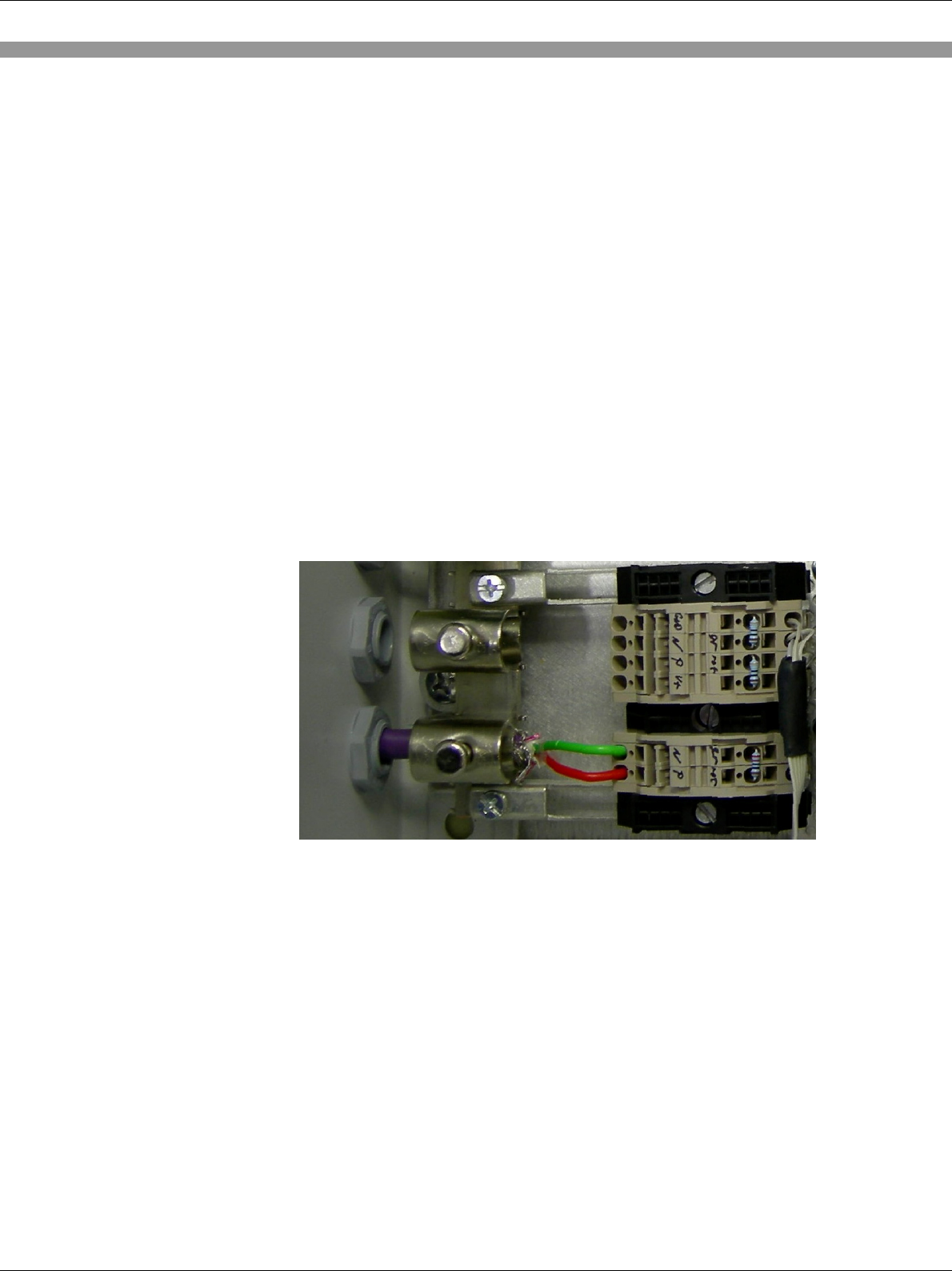
5.6.2 Connect the earth ground
Electrical Installation
RFI341 Radio Frequency Interrogator
30 SICK AG − Division Auto Ident - Germany - All rights reserved 8012640/2008-03-10
5.6.3 Connect the RS232 Interface
If the RS-232 interface is intended to be use, e.g for parameterisation with
the SICK software, it needs to be ensured that the Profibus interface
interface is disabled (switch at the CMF, see CMF documentation).
5.6.4 Connect the Profi-Bus Interface
If the Profibus interface should be used than the terminals needs to be
connected. Dependent of the position in a network the terminal resistors
need to be removed. For detailed information please refer to the CMF
gateway documentation (8010461). The max datarate of the Profibus
interface is limited to 1,5Mbit/sec.
RFI341 Radio Frequency Interrogator
31 SICK AG − Division Auto Ident - Germany - All rights reserved 8012640/2008-03-10
6. Operation
6.1 Overview of the Start-up Steps
• Start the RFI341 with the default settings (Quick start)
• Connect to the PC or HOST
• Use the Demo/Parameterisation-Software to run the device or
• Control the device by using the related command strings or
• Configure (parameterise) the RFI341 for the desired application
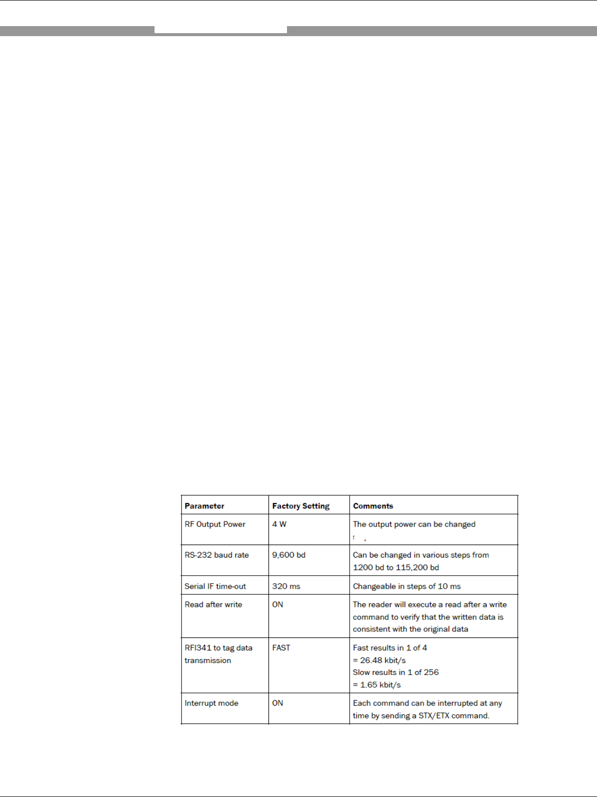
6.2 Factory Default Settings
The table below shows the factory setting of the RFI341. The factory default
parameters are such that the RFI341 can be put into operation immediately
or following a few minor adjustments.
The default settings of the parameters are stored permanently in the RFI341
EEPROM memory. To display the stored settings, use either the PC and
execute the “REQUEST SYSTEM SETTINGS, 1010” command as described
in the document “Telegram Listing RFI341” or the PC Software and request
the display of the system settings. To change the settings, use the software
“EDIT SYSTEM SETTINGS, 1011” command.
Operation
RFI341 Radio Frequency Interrogator
32 SICK AG − Division Auto Ident - Germany - All rights reserved 8012640/2008-03-10
6.3 Configuration (Parameterisation)
The RFI341 is configured locally in accordance with the existing application.
The read, evaluation and output characteristic, can be parameterised as
required. The factory default settings or the application specific parameter
set is in affect before changes are made.
The RFI341 can be configured by using either the PC Demo Software or the
specific commands sent by the user host software.
6.3.1 Antenna Output Power
The output power of the RFA3xx antennas can be changed in four steps.
When the maximum power is not required to meet the system requirements,
this can be used to prevent reader interference.
(available steps: 4W / 2W / 1W / 0,75W )
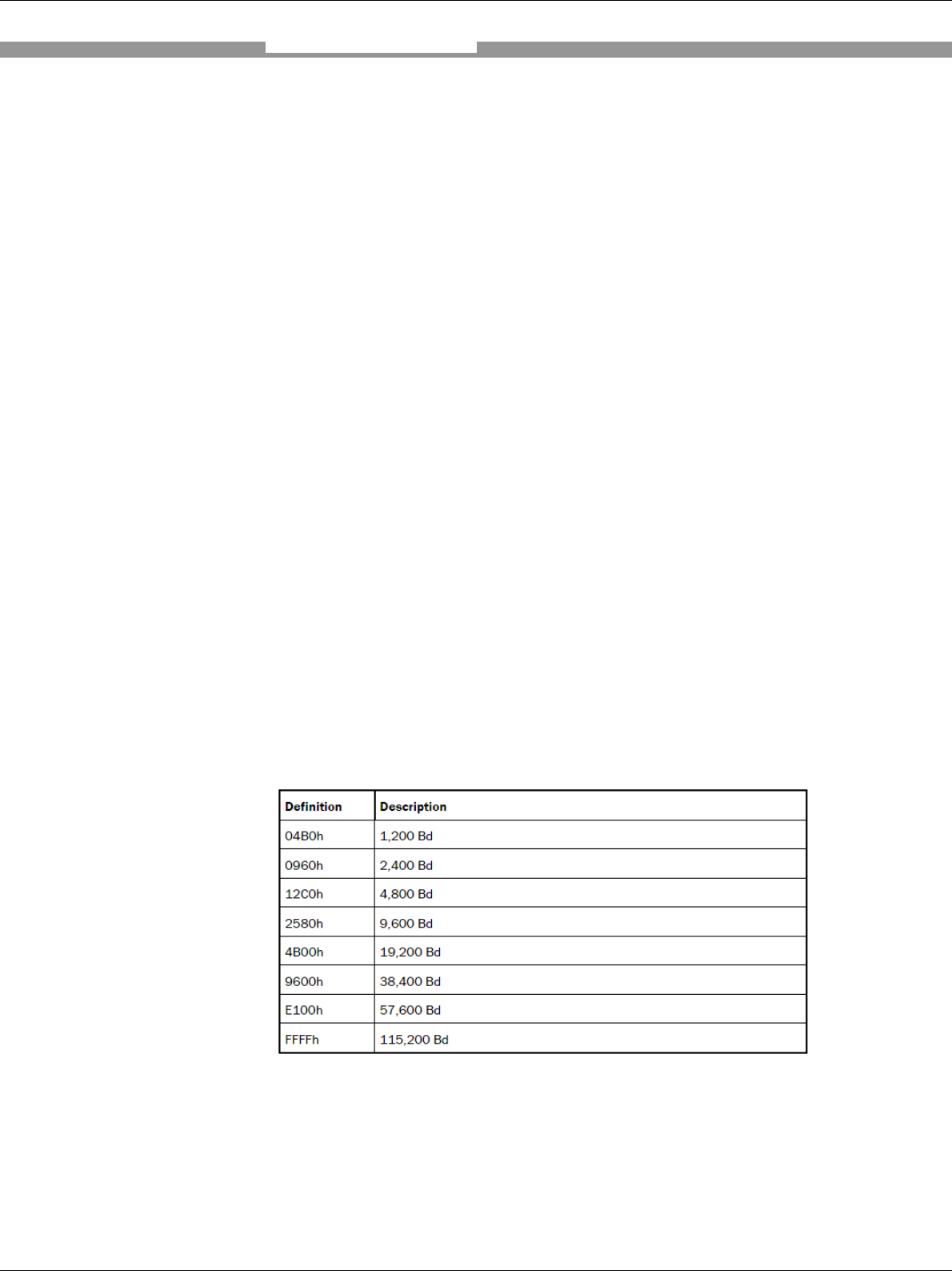
6.3.2 RS232 Data Interface
The RS 232 data interface data rate can be set to different speeds. The
RFI341 supports the following settings.
Protocol
Operation

RFI341 Radio Frequency Interrogator
33 SICK AG − Division Auto Ident - Germany - All rights reserved 8012640/2008-03-10
6.3.3 Oscillator Switch off delay
Switching off the HF-field results in a power-on reset of all tags present in the
reader field. The length of time set should be checked very carefully. In the
worse case scenario, the tags which are in the selected or quiet mode will
loose this status. Depending on the application, it could be necessary to set
this time to a lower value. The factory default setting is 500 ms.
6.3.4 Read after Write Verify
The interrogator can be set so that it will automatically execute a read after
write if data is written to the transponder. This requires some time and the
user can define whether or not he wants to receive this verification. The
factory default setting is set “ON”.
6.3.5 HF Reset for Inventory Commands
Setting this feature to “ON” results in a HF reset before an inventory
command is executed. The factory default setting is “ON”.
Operation

RFI341 Radio Frequency Interrogator
34 SICK AG − Division Auto Ident - Germany - All rights reserved 8012640/2008-03-10
6.4 ISO/IEC 15693 settings
The ISO/IEC 15693 Standard allows various settings. To configure correctly
for the specific application, it is recommended that the user have a basic
understanding of the features described in this standard. Supported functions
are:
• Changing of the forward link modulation depth. The factory
default setting is 20/100 %
• Changing of the return link modulation type (ASK/FSK). The factory
default setting is FSK.
• Transponder response data rate (high or low). The factory default setting
is high.
• AFI (Application Field Identifier). If this byte is set to 00h, the interrogator
will ignore the AFI, otherwise it will use the set value.
• Inverse UID (start with the LSB instead the MSB). The factory default
setting is reverse byte order.
• One Slot inventory: If this value is set to one, the inventory command will
start with one time-slot.
• Others (refer to document “Telegram Listing RFI341”)
Operation

RFI341 Radio Frequency Interrogator
35 SICK AG − Division Auto Ident - Germany - All rights reserved 8012640/2008-03-10
7. Maintanance
7.1 Maintenance
The RFI341 does not require maintenance.
7.2 Disposal
Irreparable devices or devices that are no longer required are to be disposed
of in an environmentally-friendly manner:
1. Always observe the applicable national waste disposal regulations.
2. Remove the RFI341 housing.
3. Remove the electronic modules and the connection cables.
4. Send the metal housing to be recycled.
5. Send the electronic modules and connection cables for disposal as special
waste. At present, SICK AG does not accept the returning of unusable or
irreparable devices.
Maintanance
RFI341 Radio Frequency Interrogator
36 SICK AG − Division Auto Ident - Germany - All rights reserved 8012640/2008-03-10
8. Troubleshooting
8.1 Installation errors
The RFA3xx antenna is installed incorrectly with respect to the object
carrying the transponder, e.g., the relationship between the transmitted
power, antenna size and transponder form factor is unfavourable.
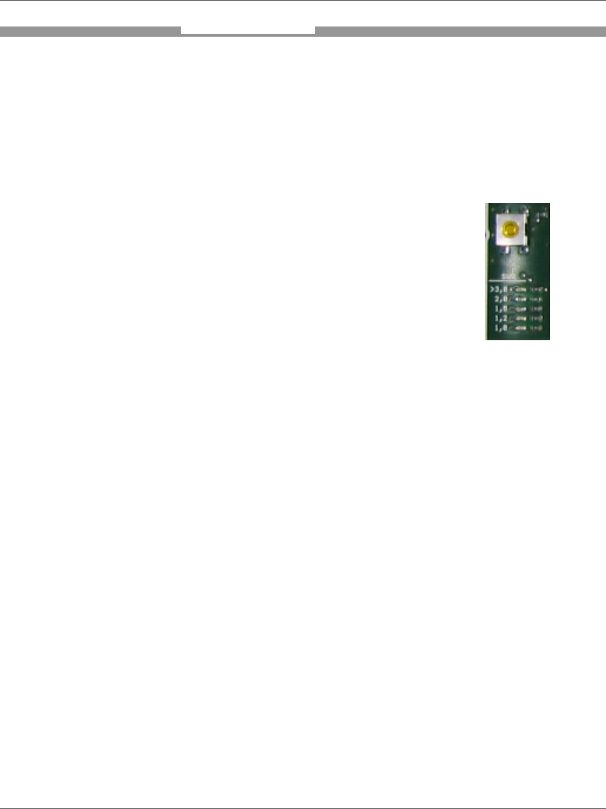
• The RFA3xx antenna is installed close to metal that de-
tunes the antenna circuit. This can be checked either by
the SWR measurement inside the device. To start this
the background function need to be interrupted. Than
the SWR bottom need to be switched. The LED bar
indicates the SWR status. In addition a beeper signals
with frequency the status (high frequency is good, low
frequency is bad). Tuning is possible by inside antenna
tunable capacitors.
• The trigger sensor is positioned incorrectly.
• Other interrogator antennas are causing interference.
8.2 Electrical Connection Errors
• Interfaces on the RFI341 are connected incorrectly.
8.3 Parameterisation Errors
• Functions are not adjusted to local conditions, e.g., communication
parameters for the host interface are set incorrectly.
• ISO or system settings are not in accordance with the transponders
used, e.g., wrong AFI used..
Troubleshooting
RFI341 Radio Frequency Interrogator
37 SICK AG − Division Auto Ident - Germany - All rights reserved 8012640/2008-03-10
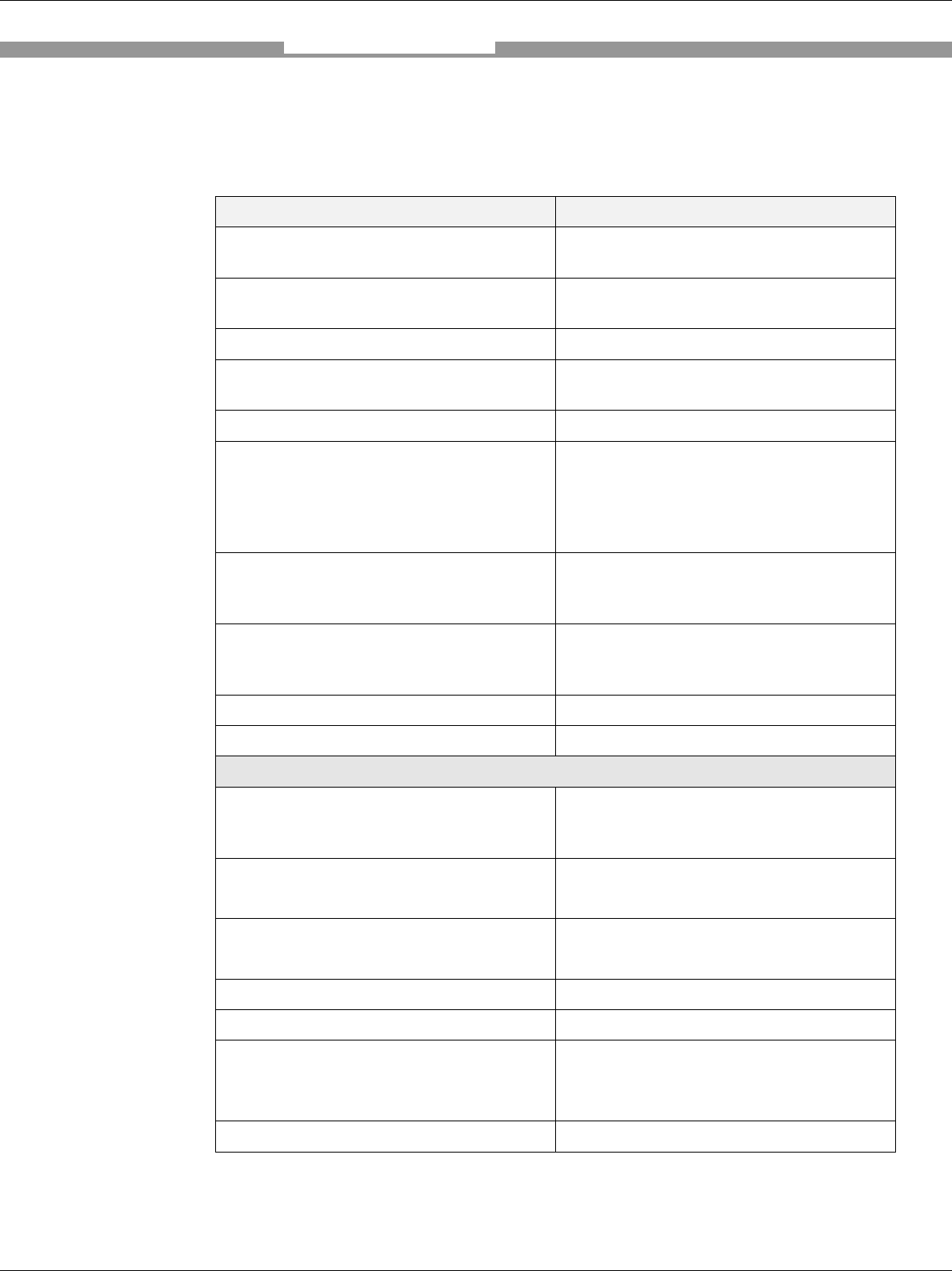
9. Technical Data
9.1 RFI341-1503
Type RFI341 Host/Data Interface
Protocol STX/ETX (see document “ RFI341
Telegram Listing 8011237 ”)
Terminal data interface RS-232 9,600 baud to 115kbaud, start, stop, no
parity (8N1)
Ethernet TCP/IP - 10/100Mbit
RF Interface Carrier Frequency 13.56 MHz
(13.553 to 13.567 MHz)
RF output power (max) 4 W (±1 dB)
Switching Inputs Vinhigh max = 30 V,
Vinhigh typ = 24 V,
Vinhigh min = 18 V,
Vinlow max = 1,5 V
Iinmax < 4mA
Switching Outputs Vout = Vin (power supply) – <=1V
Iout max = 400mA restive load ; short cut
and overload protected
Mains power supply Operating Voltage 24V DC (20..29V);
- slope time < 3 sec
- start up time < 4 sec.
Supply Current < 2,0A
Protection Class 3
Mechanical
Housing (dimensions) except stainless
steal where the with is 210mm instead of
200mm
300 mm x 200 mm x 120 mm
(15.8 in x 7.9 in x 4,7 in)
Antenna Connector BNC (standard and M12 version)
TNC (stainless steel version)
Enclosure rating / protection class IP65 (standard and M12 version)
IP66 (stainless steel version)
Operation temperature -20 °C to 50 °C
Storage temperature -20 °C to 60 °C (-4 °F to 142 °F)
Colour SICK blue RAL5012 (standard an M12
Version)
Without paint (stainless steel version)
Mechanic IEC 60068-2-64 (10..500 Hz;1 grms)
Technical Data
RFI341 Radio Frequency Interrogator
38 SICK AG − Division Auto Ident - Germany - All rights reserved 8012640/2008-03-10
Warning! This is a device for usage in Class A. Therefore radio interference could
appear in living quarters.
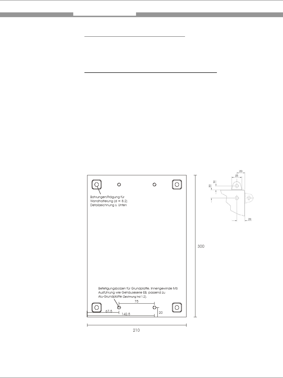
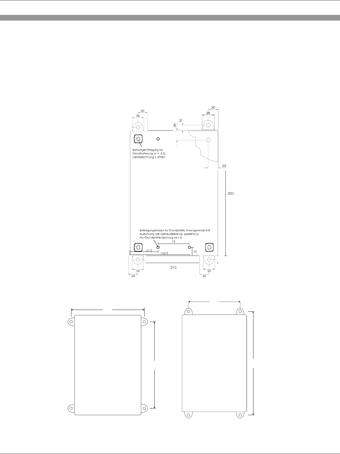
9.2 Dimensional Drawing
Standard and M12 Version do have the brackets to the side whereas the stainless steel
version do have it to the top and bottom like shown in the picture below
Drill template (standard version) (stainless steel version)
220mm
260mm
160mm
320mm

RFI341 Radio Frequency Interrogator
39 SICK AG − Division Auto Ident - Germany - All rights reserved 8012640/2008-03-10
10. Appendix
10.1 Accessories
Antenna(s) RFA3xx
Splitter
Multiplexers
Antenna connector converter
RS232 cable (open end)
RS232 cable (M12 / SUBD9)
Mux-Control cable
Transponder
10.2 Glossary, Standard Basics, and Abbreviations
AM
Amplitude Modulation
A method of combining an information signal and a RF carrier with a different
voltage level assigned to a digital 0 and 1.
Antenna
A radio frequency transducer.
Antenna de-tuning
Relative to RFID implementations, the reduction in the amount of energy that
is available to power a tag or the reduction of the amplitude of the signal
reaching the reader due to the environment.
Anticollision
See collision avoidance. Collision avoidance algorithm. RFID interrogator
firmware that intercepts multiple simultaneous tag signals, sorts responses
and initiate a communication protocol to sequentially collect the information.
Frequency
The number of repetitions of a complete waveform in a specific period of
time.1 kHz equals 1,000 complete waveforms in one second. 1 MHz equals
one million waveforms per second.
DSFID
Data Storage Format IDentifier
EOF

RFI341 Radio Frequency Interrogator
40 SICK AG − Division Auto Ident - Germany - All rights reserved 8012640/2008-03-10
End of Frame
Host computer
The computer running software that interacts with the RFID and other
devices such as a warehouse management system.
IC
Integrated Circuit
Inductive coupling
Method of creating a current in a conductor without connecting it directly to a
power source. A tag responses to a reader by inductively coupling with the
reader carrier signal.
Interference
Any environmental condition that creates electrical noise at the same
frequency as the communication signal.
Interrogator
Another term for a reader.
ITF
Interrogator Talks First
LSB
Least Significant Bit
Modulation index
An index equal to (a-b)/(a+b) where a and b are the peak and the minimum
signal amplitudes respectively.
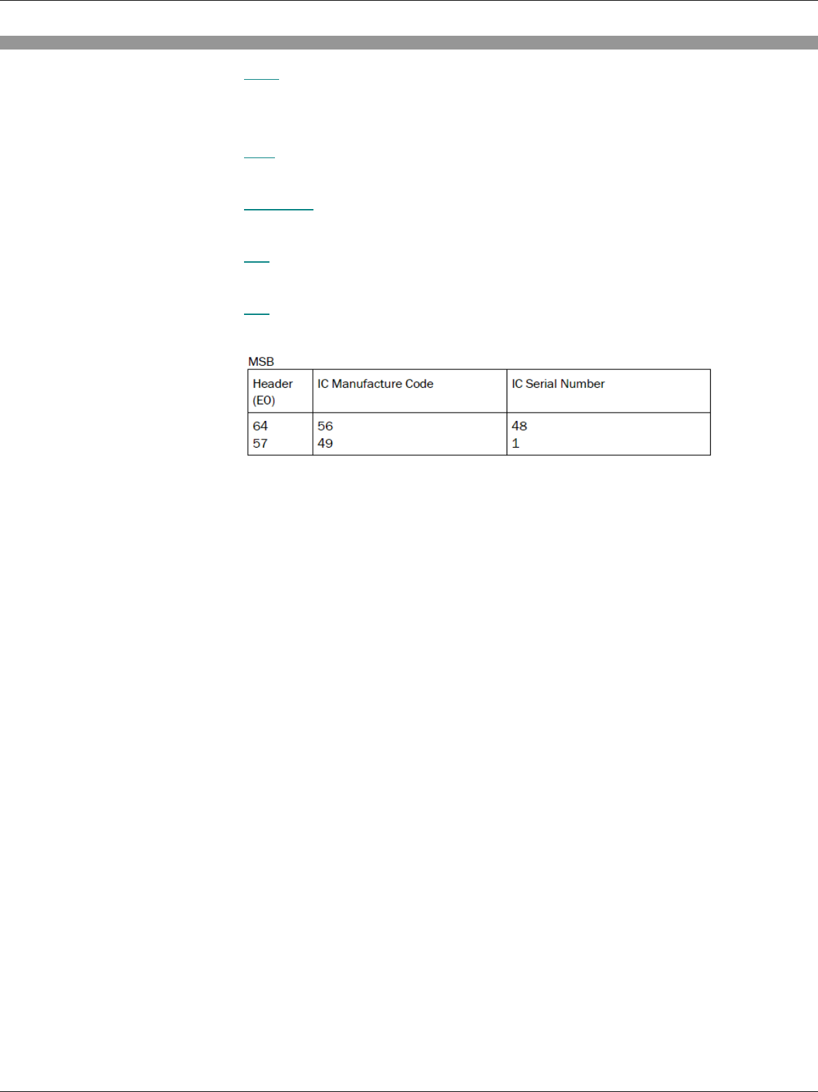
MSB
Most Significant Bit
Passive RFID tag
Passive tags do not have an on-board powered transmitter. They are
activated by the electromagnetic waves of a reader.
PPM
Pulse Position Modulation
Reader
Also called an interrogator. The reader communicates with the RFID tag and
passes the information in digital form to a host computer system.
Read range
The distance from which a reader can communicate with a tag. The range is
influenced by the power of the reader, antenna size, transponder form factor
and environmental conditions.
RFI341 Radio Frequency Interrogator
41 SICK AG − Division Auto Ident - Germany - All rights reserved 8012640/2008-03-10
RFID
Radio Frequency IDentification. A method of tracking using radio waves that
trigger a response from a device attached to an item.
SOF
Start of Frame
Subcarrier
A signal of frequency fs used to modulate the carrier of frequency f0
Tag
A generic term for radio frequency identification device
UID
Universal IDentification code
10.3 ISO/IEC 15693 – ISO/IEC 18000-3 Mode 1 Basics
The ISO/IEC 15693 is one of a series of international standards describing
the parameters for identification cards as defined in ISO/IEC 7810 and the
use of such cards for international interchange.
The ISO/IEC 15693 is intended to allow operation of vicinity cards in the
presence of other contactless cards conforming to the ISO/IEC 10534 and
ISO/IEC 14443 standards.
The ISO/IEC 18000 series is defined mainly for item management. The Part
3, Mode 1 is compatible with ISO/IEC 15693.
This summary should be used only as a basis for understanding the features
given by the ISO/IEC15693 standard. The full documentation can be ordered
from ISO/IEC.

RFI341 Radio Frequency Interrogator
42 SICK AG − Division Auto Ident - Germany - All rights reserved 8012640/2008-03-10
ISO/IEC 15693-2 Air Interface and Initialisation
This part of ISO/IEC 15693 describes the electrical characteristics of the
contactless interface between the transponder and the interrogator. The
interface includes power and bi-directional communications.
Initial Dialog for ISO15693 Transponder
• Activating of the transponder (interrogator RF power on)
• Transponder waiting for a command from the interrogator (ITF)
• Receiving the command from the interrogator
• Transmitting the response to the interrogator
Power Transfer
The power transfer from the interrogator antenna to the transponder is
accomplished by radio frequency via coupling antennas. The RF operating
field that supplies power to the transponder from the interrogator is
modulated for communication.
Frequency
The transponder frequency is 13.56 MHz ± 7 kHz
Communications Signal Interface
For some parameters, special modes are available to comply with different
international radio regulations and application requirements.
Modulation
Communications between interrogator and transponders takes place using
the ASK modulation principle. If the modulation index is set to 100 %, the
noise sensitivity is less. A modulation index of, e.g., 20 % will increase the
read/write performance but also increase the noise sensitivity.
Data Rate and Data Encoding
The transponder support two data coding modes
(1 out of 4 at 26.48 kbit/sec and 1 out of 256 at 1.65 kbit/sec).

RFI341 Radio Frequency Interrogator
43 SICK AG − Division Auto Ident - Germany - All rights reserved 8012640/2008-03-10
ISO/IEC 15693-3 Anticollision and Transmission Protocol
This part of ISO/IEC 15693 describes the anticollision and transmission
protocols.
The anticollision is based on a UID that each tag supports. The length of this
ID is 64 bits and it is guaranteed by the manufacture of the IC that the ID is
unique
AFI
The Application Field Identifier (AFI) should – if available – represent the
application for which the transponder is used. It can be programmed and
locked within the transponder with the commands given in the document
“Telegram Listing RFI341”.The AFI consists of 8 bits. If no applicable
preselection is possible, use “0h”..
The support of the AFI feature is optional. That means it is possible that ISO
15693 compliant transponders do not offer this AFI feature. It is recommend
that only those transponders that offer this AFI byte be used.
Therefore, check carefully the selection of the transponder IC type and the
requirements given by the application.
DSFID
The Data Storage Format Identifier (DSFID, 8 bit) can be used to indicate in
which manner the user data is structured in the user memory. If no DSFID is
used, this value should be “0h”.
Anticollision
The purpose of the anticollision is to make an inventory of the transponders
present in the field by using their UIDs.
The anticollision is based on slots. The interrogator can use one or sixteen
slots. If the interrogator wants to ensure that tags are present for an
anticollision or knows that only one transponder is present in the field, the
slot length of one is adequate.
If additional transponders are in the field, the interrogator will detect this by a
erroneous CRC.
If more than one tag is in the field and the interrogator uses the 16 slots,
each transponder will calculate a number (with help from UID) between 1
and 16 and replies in a special slot. It can occur that more than one tag
replies in the same slot.

RFI341 Radio Frequency Interrogator
44 SICK AG − Division Auto Ident - Germany - All rights reserved 8012640/2008-03-10
In this case, the interrogator will skip to the next slot. Within the next
inventory session, these transponders will participate whereas those that
have been successfully read (UID) could be not present – depending on the
function, which may set these transponders to the quiet stage. This process
could be repeated until all transponders are identified. Tags colliding in a slot
could be separated with masks according to ISO Standard.
Command Codes
The ISO 15693 requires that only two commands to be mandatory in an IC.
These are “Inventory and Stay quiet”. All other commands are defined but
optional.
Therefore, ensure that the tag used supports the application requirements.
These include:
• Read and write feature
• Lock block feature
• Read and write of multiple blocks
• AFI and DSFID features
RFI341 Radio Frequency Interrogator
45 SICK AG − Division Auto Ident - Germany - All rights reserved 8012640/2008-03-10