User Manual
Subject to change without noticeSICK AGWaldkirchGermanywww.sick.com
The RFU63x interrogator is an intelligent sensor for automatic,
stationary identication and transfer of data from/to radio-
based data carriers on mobile or stationary objects. As a com-
pact read/write unit with an integrated antenna, the RFU63x
will process all conventional transponders compatible with
ISO/IEC-18000-6C in the frequency range 860 to 960 MHz,
either as a stand-alone solution or as part of a group in a
network. The RFU63x sends the read results to a higher-level
computer for further processing via its host interface or
receives corresponding commands for the processing of the
data carriers (writing, reading etc.).
The purpose of these operating instructions is to allow you
to take the RFU63x into operation quickly and easily and to
achive the rst read results with transponders. It describes
commissioning for an application with RFU63x.
Further information concerning mechanical and electrical
installation is available in the Technical Information RFU63x.
Information concerning the conguration is available in the
online help of the conguration software SOPAS ET.
The information can be accessed on the enclosed data me-
dium (DVD) or on the web page for the product RFU63x
(www.mysick.com/en/rfu63x).
• Read these instructions before commissioning the RFU63x
to familiarize yourself with the device and its functions.
• For national-specic regulations when operating the
RFU63x see “Restrictions of RFU63x operation, page 4”.
• Connect or disconnect electrical linkages between the
RFU63x and other devices only under de-energized condi-
tions. Otherwise, the devices could suffer damage.
• Conducting cross sections of the supply cable from the
customer’s power system should be designed in accor-
dance with the applicable standards. If the voltage for the
RFU63x is supplied via the CDB620-001S02 connection
module, the usable voltage range (DC 22 to 30 V) is
restricted by the use of the internal 1.25 A fuse.
Otherwise, protect the RFU63x with DC 12 to 30 V using
a separate slow-blow fuse (max. 2.5 A) in the supplying
circuit at the beginning of the cable.
• Only use the RFU63x under permitted ambient conditions
(e. g. designated region, temperature, ground potential)
( see “Technical specications, page 3”).
• Ensure that the radiated power of the antenna(s) used
does/do not exceed maximum permissible values in each
case ( see “Continuing conguration, page 2”).
• Protect the RFU63x from moisture and dust whenever the
USB socket/Micro SD card slot cover is open. The cover
on the housing must be secured with screws in order to
comply with enclosure rating IP 67. The same applies for
protective caps/plugs on unused electrical connections.
• Opening the RFU63x housing locked by screws will invali-
date any warranty claims against SICK AG.
1. Connect the communication interface (e.g. Ethernet) of the
RFU63x to the PC.
2. Where other external antennas are used (max. 3, e.g.
RFA641-3440, part no. 6034316), connect these via suit-
able connecting cables (e.g. part no. 6034081, 2 m
(6.56 ft)) to the antenna inputs of the RFU63x.
Connection module
CDB620-001S02
SOPASSOPAS
RFU63x
12
DC 22 ... 30 V
GND
Configuration
Diagnosis
"Power" e.g. "Ethernet"
e.g. cable
no. 2055419
(2 m, 6.56 ft)
e.g. cable
no. 6034414
(2 m, 6.56 ft)
EthernetEthernet
SerialSerial
...
...
Electrical connections diagram for the RFU63x
1. Optional: Attach any mounting accessories ordered sepa-
rately (mounting kit 1,2 or 3) to the RFU63x; see the
chapter “Mounting” in the Technical Information.
2. Otherwise mount the RFU63x using three M5 screws or
4 M6 screws to a bracket (to be provided by customer).
Screw the M6 screws (max. 12 mm/0.49 in) or M5 screws
(max. 9 mm/0.35 in) into the blind hole threads
( see “Device structure, page 2”).
3. Align the surface of the RFU63x’s integrated antenna
(front) and any external antennas to the data carrier on the
object. In doing so, take into account the shape, alignment
and dimensions of the antenna lobes. Exclude any large
metal surfaces present on the front where possible. If this
is not possible, mount the antenna(s) so they are not
plane-parallel to the surface.
e.g. 5°
Metal surface
Choosing the adjustment angle for the RFU63x in case of a large metal
front surface
4. Supply the RFU63x with voltage.
Following successful initialization, the LED “Device Ready”
will light up green. The power supply unit must be able to
bridge a main power drop up to 20 ms during operation.
5. Ensure no objects (or persons) are situated between the
RFU63x/antennas and the transponder during the read/
write process. This will have a damping/reecting effect on
the UHF eld generated, reducing the range and process-
ing speed of the RFU63x.
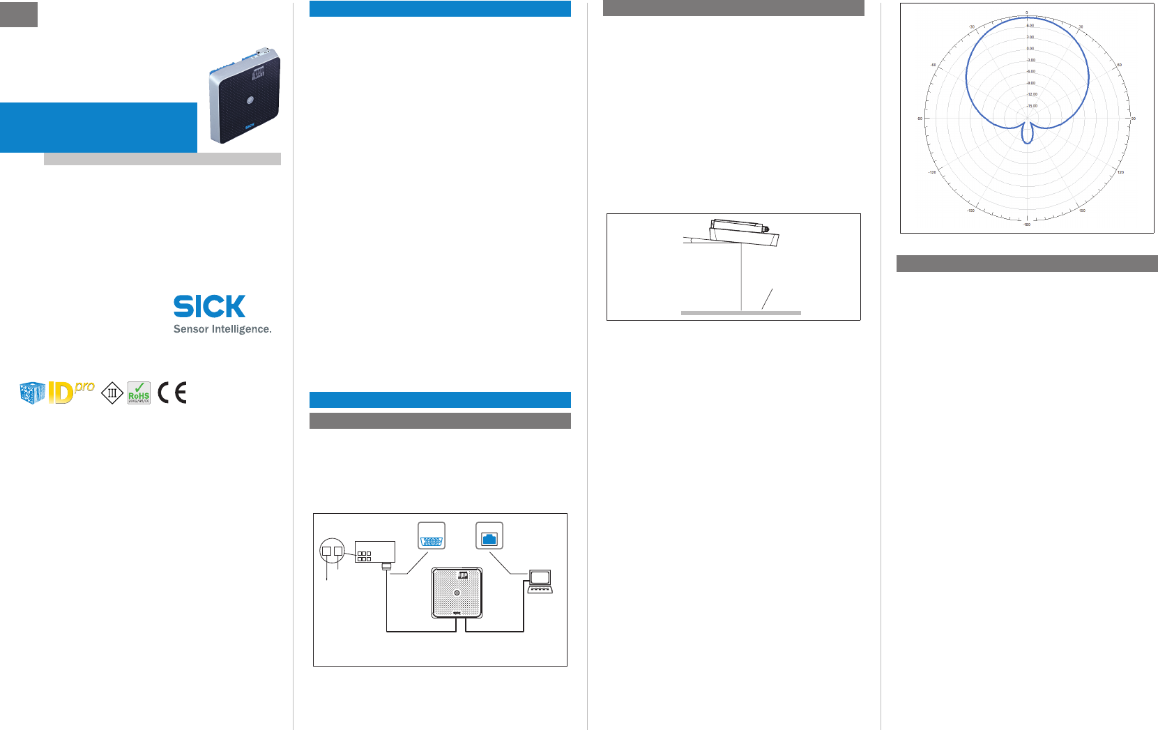
The UHF eld is inuenced by its environment such that clear
delineation of the range is not possible. Reections due to the
application can result both the range being exceeded and in
read/write gaps. In addition to the read results, the RFU63x
can also output diagnostics data that provides an indicator of
reading/writing quality. This data can be used when setting
up the system to attain optimal read results.
Another, considerably more decisive factor is the quality of
the transponder (antenna gain, integrated Transponder-IC
and associated sensitivity, reective energy) and the object
itself (plastic, wood, metal). Below is an example of an an-
tenna lobe that has been recorded in a reproducible environ-
ment (HF chamber) with a reference transponder (Dogbone,
Monza4, on wood). This is therefore only signicant for
particular applications in certain conditions.
Radiation pattern for internal antenna
Parameters of the RFU63x are adapted to the application and
fault diagnostics is performed using the SOPAS ET congura-
tion software as standard.
1. Install the software on the enclosed “Software & Manuals
Auto Ident” DVD onto the PC (alternatively, you can download
it from the website www.sick.com/software and then
install it). When doing this, choose the “complete” option,
as suggested by the installer program. You may require
administrative rights on your PC to install the software.
2. After installation, start the program option “SOPAS ET-ET”.
Path: Start > Programs > SICK > SOPAS ET Engineering
Tool > SOPAS.
3. Establish a connection between SOPAS ET and RFU63x us-
ing the wizard that opens automatically. To do this, select
the RFU63x from the available devices depending on the
connected data interface e.g. Ethernet.
SOPAS ET will start communication with the RFU63x and
load the relevant device description le for the RFU63x.
The Quick start tab will open up automatically.
1. Place one or more standard compatible UHF transponders
within the work area of the internal antenna/external
antennas of the RFU63x. The UII/EPC of the individual
transponders must be different to enable several tran-
sponders to be detected.
2. In SOPAS ET on the Quickstart tab, select the start button.
SOPAS ET will generate an automatic reading pulse (1 Hz)
and list the transponders detected below one another in
the Quickstart window ( example see next page).
RFID Interrogator (UHF)
0700
Subject to change without noticeSICK AGWaldkirchGermanywww.sick.com
Quickstart window showing two transponders detected
The process feedback LED (8) in the center of the RFU63x’s
antenna hood will light up blue by default to indicate that a
UHF eld is available and a transponder has been detected.
Lights up with medium brightness
UHF eld available
Flashes brightly and slowly 1 transponder in eld
Flashes brightly and quickly More than 1 transponder in eld
1. To access a transponder’s memory area in the RFU63x
database (read/write), click the stop button in the
Quickstart menu.
2. Select the desired transponder (click on it with the mouse).
3. Click tag access. The content of the selected transponder
will now appear in the tag access tab.
tag access window
64.3
28
9
166 13.559.5
9
32.5
83.5
40
42.5
8.2 40
80
136.8
238.6
238.6
119.3
97
0
14.5
0
19.6
24.7
29.7
34.8
39.9
119.3
45 (113.1)
(113.1)
92.4
68.4
44.4
26.4
48.4
70.4
92.4
5
0
15.1
(113.1)
17.2
0
17.2
0
52
34
13.1
6
7
6
9 ß
8
45
1 2 3
7
mm
5
8.2
9
13.1
13.5
14.5
15.1
17.2
19.6
inch
0.19
0.32
0.35
0.51
0.53
0.57
0.59
0.67
0.77
mm
24.7
26.4
28
29.7
32.5
34
34.8
39.9
40
inch
0.97
1.04
1.10
1.17
1.28
1.33
1.37
1.57
1.57
mm
80
83.5
92.4
97
113.1
119.3
138.6
166
238.6
inch
3.15
3.28
3.64
3.82
4.45
4.70
5.46
6.54
9.40
mm
42.5
44.4
48.4
45
52
59.5
64.3
68.4
70.4
inch
1.67
1.74
1.90
1.77
2.04
2.34
2.53
2.69
2.77
Ogreen Device ready
Ored Hardware fault
Ogreen Read or write successful
Ogreen UHF eld activated
Ogreen Data output via host interface
Ogreen Data trafc via CAN bus
Ogreen Data trafc via Ethernet
Ogreen Micro-SD card inserted and
operational
O = lit; = ashing
Conguration: Example of internal antenna settings (excerpt)
Conguration: Example of external antenna 2 settings (excerpt)
Enter also the power loss or gain for the relevant cable/
antenna here.
Transmit power 200 mW
The transponder’s TIDs cannot be written to.
1. In the navigation tree in the SOPAS ET, with the aid of the
further entries under parameters, edit the required tab
pages for the application (antenna conguration, selection
mask for transponder, object trigger control, data process-
ing and output, data output interface(s) and switching
inputs and outputs)
2. On the antenna configuration tab, the transmit power for
the internal and, where applicable, external antenna(s)
are set using sliding controllers. For permissible values
see “Setting the transmit power, page 2”
3. Test settings made during actual operation of the system
and make modications where applicable.
>Save the entire conguration permanently:
Parameter set in the RFU63x: Click the button.
Conguration le (project) on the PC: Click the button.
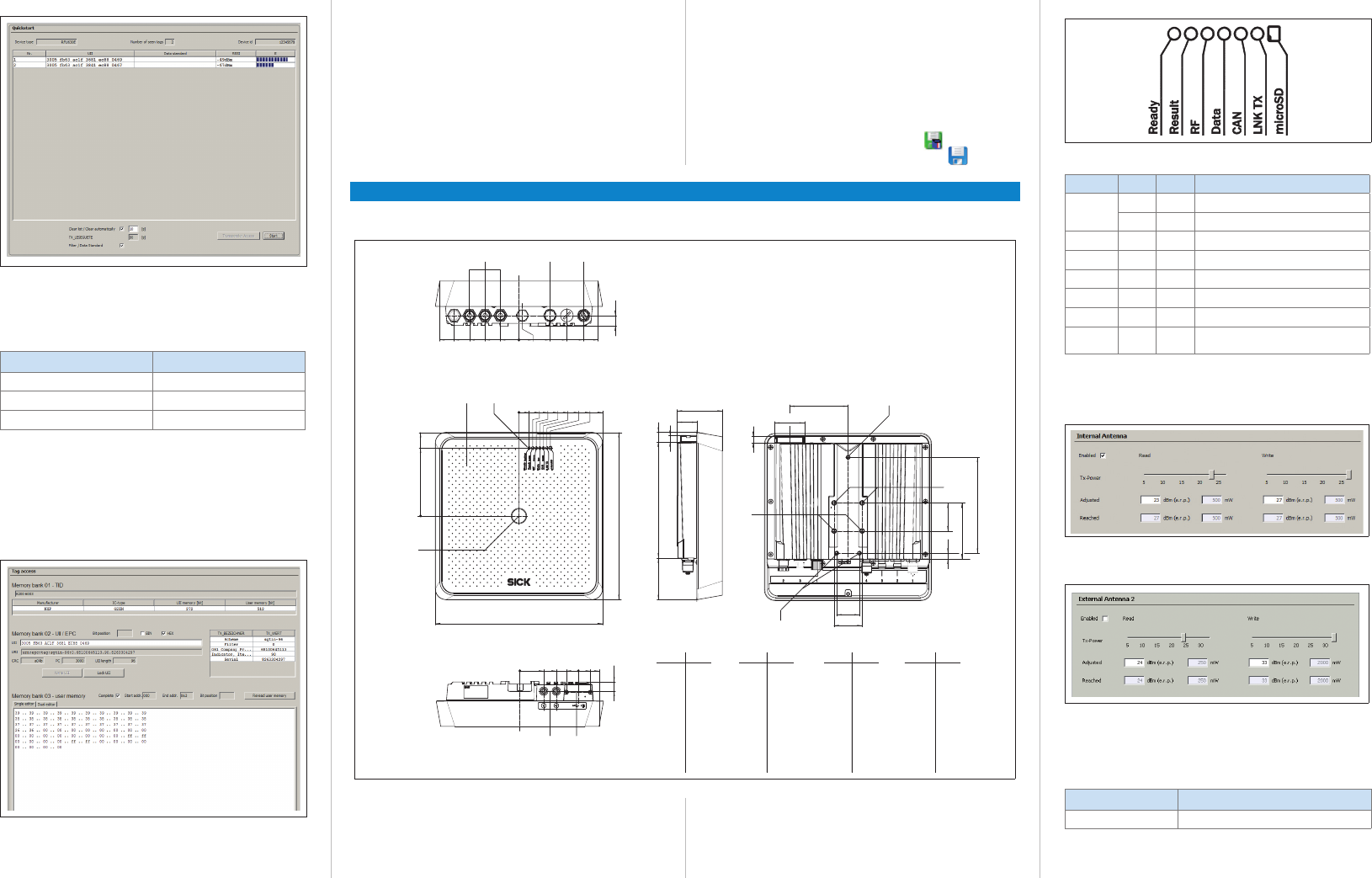
1 3 x antenna input (“external”, TNC plug, reverse)
2 “Power/Serial Data/CAN/I/O” connection (17-pin M12 plug, A-coded)
3 “Ethernet” connection (4-pin M12 socket, D-coded)
4 Hood with integrated antenna
5 7 x LEDs (status indicators)
6 3 x M5 threaded mounting holes, 9 mm (0.35 in) deep
7 4 x M6 threaded mounting holes, 12 mm (0.47 in) deep
8 1 x LED multi-color (process feedback)
9 Step ▾ and Enter p function buttons
Micro-USB socket and slot for Micro-SD card, behind screw-mounted
cover
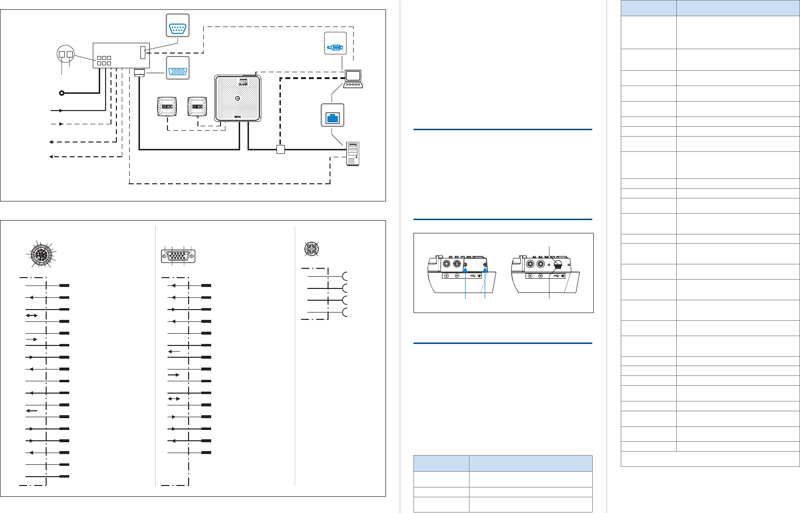
Subject to change without noticeSICK AGWaldkirchGermanywww.sick.com
“Ethernet” (HOST 2)
Input 2
(e.g. encoder)
Input 1
(e.g. external reading trigger)
Output 1
(e.g. indicator lamp)
Output 2
RFU63x
e.g. cable no. 2055419 (2 m, 6.56 ft)
”Serial RS-232/RS-422/485” (HOST 1), alternative to Ethernet Host port
CDB620-001S02
SerialSerial
e.g. cable
no. 6034414
(2 m, 6.56 ft)
Configuration
Diagnosis
SOPASSOPAS
EthernetEthernet
SerialSerial
“Power/Serial Data/CAN/I/O”
(AUX 1, HOST 1)
e.g. no. 1056432
...
...
12
DC 22 ... 30 V*)
GND
HOST
PC
Further data
processing
e.g. cable no. 2014054 (2 m, 6.56 ft)
“Serial RS-232” (AUX 1), alternative to Ethernet AUX port
“Ethernet” (AUX 3)
DC 22 ... 30 V*)
Inputs/Outputs = digital
*) due to the fuse (1.25 A, slow-blow) in the CDB620-001S02
Additional external inputs/outputs via
parameter cloning module CMC600
USBUSB
“USB” (AUX 2),
alternative to Ethernet AUX port
External antenna
(optional, e.g. RFA641)
...
1 3
Read result
“Ethernet”
“Power/Serial Data/CAN/I/0” connection Plug on the adapter cable
e.g. no. 2055419 (2 m, 6.56 ft)
CAN L
CAN H
TD+ (RS-422/485), HOST
TD– (RS-422/485),
TxD (RS-232), HOST
DC 12 ... 30 V
TxD (RS-232), AUX
RxD (RS-232), AUX
RD+ (RS-422/485), HOST
GND
RD– (RS-422/485),
RxD (RS-232), HOST
Result 1 (switching output 1)
n.c.
n.c.
Result 2 (switching output 2)
7
6
Sensor 2 (switching input 2)
Sensor 1 (switching input 1)
SensGND
4
3
2
1
5
8
9
10
11
12
13
14
15
16
17
RFU63x
M12 plug,
A-encoded
CAN L
CAN H
TD+ (RS-422/485), HOST
TD– (RS-422/485),
TxD (RS-232), HOST
DC 12 ... 30 V
TxD (RS-232), AUX
RxD (RS-232), AUX
RD+ (RS-422/485), HOST
GND
RD– (RS-422/485),
RxD (RS-232), HOST
Result 1 (switching output 1)
Result 2 (switching output 2)
7
6
Sensor 2 (switching input 2)
Sensor 1 (switching input 1)
SensGND
4
3
2
1
5
8
9
10
11
12
13
14
15
D-Sub-HD
4
3
2
1TD+
TD–
RD+
RD–
“Ethernet” connection
RFU63x
M12-Dose,
D-encoded
4
3 2
1
87 15
614
5
17
4
13
3
2
12
1
11
10
9
16
6110
5
11 15
On the plug-in memory card, the RFU63x can either addition-
ally store externally its last parameter record to be modied
(cloning) or else record diagnostics read data. The memory
card is not included in the delivery.
To ensure reliable functioning of the memory card, only use
types that have been approved by SICK.
The card slot ( see in section “Device structure, page 2”)
can be accessed on the RFU63x behind the aluminum cover.
Protect the RFU63x from moisture and dust whenever the
cover is open. The cover must be screwed down securely to
comply with IP 67 protection class.
>Only operate the RFU63x without the cover for short
periods e.g. to insert the memory card or use the USB
interface.
Micro USB socketSrews
Slot for SD card
>To remove the cover, release the two hexagon socket
screws (2 mm width across at).
A write process on the memory card by the RFU63x is indi-
cated by the “micro-SD card” LED lighting up green (5).
>During the write process, do not remove the memory card
or switch off the supply voltage.
>To remove the memory card safely, select the remove
card function under analysis tools/microsd card in the
conguration software SOPAS ET.
RFU630-13100: Europe
RFU630-13101: USA/Canada
V1.1
Europe: 865.6 to 867.6 MHz
USA/Canada: 902.75 to 927.25 MHz
1 internal antenna, adjustable:
RFU630-13100: 2 W (ERP*)
RFU630-13101: 4 W (EIRP**)
3 external antennas: each conducted power up
to +30 dBm, adjustable
Circular polarization, 9 dBic gain,
axial ratio < 2 dB, aperture angle 72°,
front-to-back ratio > 17 dB
EPCglobal UHF Class 1 Generation 2
ISO/IEC 18000-6C
Max. 3 m (9.84 ft), depending on transponder
used and ambient conditions
HOST 1 (0.3 to 115.2 kBd) for data output
AUX 1 (57.2 kBd) for conguration
AUX 2 (USB 2.0) for conguration
CAN (CANopen®), 20 KBit/s to 1MBit/s.
Max. bus length 30 m (98.42 ft)
HOST 2 (TCP/IP) for data output
AUX 3 (TCP/IP) for conguration
10/100 MBit/s
Services: DHCP, NTP, HTTP, mDNS, DNS-SD
HOST via external CDF600-0120 module
HOST via external CDM425 module
2 x IN (Vin = max. 32 V, Iin = max. 5 mA),
opto-decoupled, adjustable debouncing time
2 x OUT (in each case Iout ≤ 100 mA), not
electrically isolated from the supply voltage,
short-circuit proof/temperature-protected
Beeper, function adjustable via SOPAS ET
7 x LEDs (status indicators) on front at top.
1 x LED (process feedback) front center,
function/color adjustable via SOPAS ET
2 x, for Auto setup, other functions adjustable
via SOPAS ET
Micro-SD card (optional) or externally via
CMC600 module in CDB620-001S02 connec-
tion module
DC 12 to 30 V, PELV as per EN 61140 (2002-
03),
DC 22 to 30 V when using CDB620-
001S02 connection module
Typically < 20 W (switching outputs without
load and at full transmit power)
1 x 17-pin M12 circular plug
1 x 4-pin M12 circular socket
3 x TNC (rev), mono-static, impedance: 50 Ω
Aluminum/approx. 3.5 kg (7 lb.)
III, according to EN 61140: 2006-08
IP 65/67 (EN 60529: 1991-10/A2: 2000-02)
RFU630-13100: ETSI EN 302 208-2 V. 1.4.1
RFU630-13101: FCC Part 15.247
Acc. to EN 60950-1:2006-04/A11:2009-03
Operation: –20 °C to +50 °C (–4 to +122 °F)
Storage: –30 °C to +70 °C (–22 to +158 °F)
0 to 90%, non-condensing
NTP-network-time protocol/none
*ERP = Effective Radiated Power
**EIRP = Equivalent Isotropic Radiated Power
For further technical specications, see the online data sheet
on the product web page (www.mysick.com/en/rfu63x).

Subject to change without noticeSICK AGWaldkirchGermanywww.sick.com
8014333/Draft2/2011-12-21 ∙ TEO/HE ∙ Printed in Germany (2011-11) ∙ All rights reserved ∙ Subject to change without notice
On delivery, the RFU63x is congured such that its frequency
band can be operated in the designated region (Europe) with-
out interfering with any protected frequencies (e.g. cellular
telephone networks). Operating the same RFU63x in other
regions may interfere with protected frequencies however.
>Only use the RFU63x in the regions for which it was
bought.
>When selling on the RFU63x, always inform the buyer
about its designated region.
• France: operation not permitted in the near of 13 military
zones (required distance of a radius of 20 km around).
• Lithuania: resctrictions possible (information not available
at present).
• Russia: a license is need for operation.
• USA: This device complies with part 15 of the FCC Rules.
Operation is subject to the following two conditions: (1)
This device may not cause harmful interference, and (2)
this device must accept any interference received, includ-
ing interference that may cause undesired operation.
To comply with FCC part 15 rules in the United States, the
system must be professionally installed to ensure compli-
ance with the Part 15 certication. It is the responsibility
of the operator and professional installer to ensure that
only certied systems are deployed in the United States.
The use of the system in any other combination (such as
co-located antennas transmitting the same information) is
expressly forbidden.
This equipment complies with FCC radiation exposure lim-
its set forth for an uncontrolled environment. This equip-
ment should be installed and operated with minimum
distance 20 cm between the radiator & your body.
• USA/Canada: This Class A digital apparatus complies
with Canadian ICES-003. Changes or modications not
expressly approved by the party responsible for compliance
could void the user’s authority to operate the equipment.
Note: This equipment has been tested and found to comply
with the limits for a Class A digital device, pursuant to part
15 of the FCC Rules. These limits are designed to provide
reasonable protection against harmful interference when
the equipment is operated in a commercial environment.
This equipment generates, uses, and can radiate radio
frequency energy and, if not installed and used in ac-
cordance with the instruction manual, may cause harmful
interference to radio communications. Operation of this
equipment in a residential area is likely to cause harmful
interference in which case the user will be required to cor-
rect the interference at his own expense.
• Canada: Cet appareil numérique de la classe A est
conforme à la norme NMB-003 du Canada.
Le présent appareil est conforme aux CNR d’Industrie
Canada applicables aux appareils radio exempts de
licence. L’exploitation est autorisée aux deux conditions
suivantes : (1) l’appareil ne doit pas produire de brouillage,
et (2) l’utilisateur de l’appareil doit accepter tout brouillage
radioélectrique subi, même si le brouillage est susceptible
d’en compromettre le fonctionnement.
aa
The RFU63x is designed to be operated in a system with
procient grounding of all connected devices and mounting
surfaces at the same ground potential. If this condition is not
met, equipotential bonding currents may ow along the cable
shields, leading to the following dangers: dangerous contact
voltage on the metal housing, incorrect function or irreparable
damage to the RFU63x as well as heating up of the cables,
even leading to spontaneous combustion.
>To nd information about measures to safeguard against
dangers, refer to the “Electrical installation” chapter in the
Technical Information (PDF) on the accompanying DVD or
on the product’s web page (www.mysick.com/en/rfu63x).
• RFU63x in the version ordered is equipped with protective
caps/plugs on its electrical connections
• “Software & Manuals Auto Ident” DVD (part no. 2039442)
• Printed operating instructions in German and English and
other languages where applicable in form of PDF on DVD.
• Any optionally ordered accessories
The RFU63x does not contain any components requiring
maintenance.
>If the antenna hood (plastic) becomes soiled, clean it
(e.g. the metal dust) using a soft, damp cloth (using a mild
cleaning agent) to obtain the maximum read/write rate.
Additional information about the RFU63x and its optional
accessories can be found in the following places:
• RFU63x technical information (supplementary information
on mounting, electrical installation etc. plus overview list
and license texts for open source software)
• These operating instructions in English and German
• SOPAS ET conguration software with integrated online
help
• Ordering information in the RFU63x product information
• Product catalog Identication Solutions
• Documents of the accessories
• Adequate accessories
• Detailed technical specications (online data sheet)
• Dimensional drawing and 3D CAD dimension models in
various electronic formats
• Product catalog Identication Solutions
• RFU63x product information
• RFU63x operating instructions in English and German as
well as in further languages if applicable
• EC Declaration of Conformity
• Overview of command strings
• Updates of the SOPAS ET conguration software
• All publications contained on the aforementioned DVD
(via links)
• Overview of command strings for the RFU63x
Support is also available from your sales partner:
www.sick.com/worldwide.
The rmware of the RFU63x was developed using open
source software.
The user is exclusively responsible for any modications
made to open source components. All warranty claims shall
be invalidated in such cases.
The following exclusion from liability applies to the
in relation to the rights holders:
This program is distributed in the hope that it will be of use,
but with no guarantee of this; neither is there any implied
guarantee of marketability or suitability for a particular pur-
pose. For details, see the GNU General Public License.
With regard to the , we
refer to the exclusions from liability of the rights holders in
the license texts on the supplied “Software & Manuals Auto
Ident” DVD.
For the RFU63x product, SICK uses unmodied open source
software and, as far as required and permitted in accordance
with the relevant license conditions, modied open source
software.
The rmware of the RFU63x is therefore subject to the copy-
rights listed below.
Please refer to the technical information for the RFU63x on
the supplied DVD for the corresponding license conditions.
Technical information can be downloaded free of charge from
the following address: www.mysick.com/en/rfu63x.
1. NCURSES – 5.7- License:
Copyright (c) 2006 Free Software Foundation, Inc.
2. Z-Lib 1.2.3:
Copyright (C) 1995-2004 Jean-loup Gailly and Mark Adler
3. e2fsprogs-1.41.11 (UUID-license based on BSD 3-clause license):
Copyright (C) 1996, 1997 Theodore Ts‘o.
4. Dropbear – 0.52.tar.bz2:
Copyright (c) 2002-2008 Matt Johnston - Portions copyright (c) 2004 Mihnea
Stoenescu
4.1 Import code in keyimport.c is modied from PuTTY‘s import.c, licensed as
follows: PuTTY is copyright 1997-2003 Simon Tatham - Portions copyright
Robert de Bath, Joris van Rantwijk, Delian Delchev, Andreas Schultz, Jeroen
Massar, Wez Furlong, Nicolas Barry, Justin Bradford, and CORE SDI S.A.
5. OpenSSH – 5.1p1
5.1 Cryptographic attack detector for ssh - source code: Copyright (c) 1998
CORE SDI S.A., Buenos Aires, Argentina.
5.2 Copyright 1995, 1996 by David Mazieres <dm@lcs.mit.edu>.
5.3 Copyright (c) 1983, 1990, 1992, 1993, 1995 The Regents of the
University of California.
5.4 Remaining components of the software are provided under a standard
2-term BSD licence with the following names as copyright holders:
Markus Friedl, Theo de Raadt, Niels Provos, Dug Song, Aaron Campbell,
Damien Miller, Kevin Steves, Daniel Kouril, Wesley Grifn, Per Allansson,
Nils Nordman, Simon Wilkinson
Portable OpenSSH additionally includes code from the following copyright
holders, also under the 2-term BSD license: Ben Lindstrom, Tim Rice,
Andre Lucas, Chris Adams, Corinna Vinschen, Cray Inc., Denis Parker,
Gert Doering, Jakob Schlyter, Jason Downs, Juha Yrjölä, Michael Stone,
Networks Associates Technology, Inc., Solar Designer, Todd C. Miller,
Wayne Schroeder, William Jones, Darren Tucker, Sun Microsystems, The
SCO Group, Daniel Walsh
5.5 Portable OpenSSH contains the following additional licenses:
a) snprintf replacement: Copyright Patrick Powell 1995
b) Compatibility code (openbsd-compat): Some code is licensed under
a 3-term BSD license, to the following copyright holders: Todd C.
Miller, Theo de Raadt, Damien Miller, Eric P. Allma, The Regents of the
University of California, Constantin S. Svintsoff
c) Some code is licensed under an ISC-style license, to the following
copyright holders: Internet Software Consortium: Todd C. Miller, Reyk
Floeter, Chad Mynhier
d) Some code is licensed under a MIT-style license to the following
copyright holders: Free Software Foundation, Inc.
6. GNU GENERAL PUBLIC LICENSE (Version 2, June 1991): Copyright (C) 1989,
1991 Free Software Foundation, Inc., 51 Franklin Street, Fifth Floor, Boston, MA
02110-1301 USA
6.1 BusyBox 1.16.1: Copyright (C) 1989, 1991 Free Software Foundation,
Inc., 51 Franklin Street, Fifth Floor, Boston, MA 02110-1301 USA
6.2 iproute2-2.6.34: Copyright (C) 1989, 1991 Free Software Foundation,
Inc., 51 Franklin Street, Fifth Floor, Boston, MA 02110-1301 USA
6.3 kexec-tools-2.0.1: Copyright (C) 1989, 1991 Free Software Foundation,
Inc., 51 Franklin Street, Fifth Floor, Boston, MA 02110-1301 USA
6.4 libelf-0.8.12.: Copyright (C) 1989, 1991 Free Software Foundation, Inc.,
51 Franklin Street, Fifth Floor, Boston, MA 02110-1301 USA
6.5 libgcc: Copyright (C) 1989, 1991 Free Software Foundation, Inc., 51
Franklin Street, Fifth Floor, Boston, MA 02110-1301 USA
6.6 ltrace-0.5: Copyright (C) 1989, 1991 Free Software Foundation, Inc., 51
Franklin Street, Fifth Floor, Boston, MA 02110-1301 USA
6.7 lzo-2.03: Copyright (C) 1989, 1991 Free Software Foundation, Inc., 51
Franklin Street, Fifth Floor, Boston, MA 02110-1301 USA
6.8 mtd-utils-1.3.1: Copyright (C) 1989 , 1991 Free Software Foundation,
Inc., 51 Franklin Street, Fifth Floor, Boston, MA 02110-1301 USA
6.9 porcps-3.2.8 (only ps used): Copyright (C) 1989, 1991 Free Software
Foundation, Inc., 51 Franklin Street, Fifth Floor, Boston, MA 02110-1301
USA
6.10 udev-119: Copyright (C) 1989, 1991 Free Software Foundation, Inc., 51
Franklin Street, Fifth Floor, Boston, MA 02110-1301 USA
7. libstdc++:
GNU LESSER GENERAL PUBLIC LICENSE (Version 3, 29 June 2007): Copyright
(C) 2007 Free Software Foundation, Inc. <http://fsf.org/>
8. Glibc 2.8
8.1 GNU LESSER GENERAL PUBLIC LICENSE (Version 3, 29 June 2007):
Copyright (C) 2007 Free Software Foundation, Inc. <http://fsf.org/>
8.2 GNU GENERAL PUBLIC LICENSE (Version 3, 29 June 2007): Copyright ©
2007 Free Software Foundation, Inc. <http://fsf.org/>
9. libusb
9.1 Copyright (C) 2007-2008 Daniel Drake <dsd@gentoo.org>
Copyright (c) 2001 Johannes Erdfelt <johannes@erdfelt.com>
This library is free software; you can redistribute it and/or modify it under
the terms of the GNU Lesser General Public License as published by
the Free Software Foundation; either version 2.1 of the License, or (at
your option) any later version.This library is distributed in the hope that
it will be useful, but WITHOUT ANY WARRANTY; without even the implied
warranty of MERCHANTABILITY or FITNESS FOR A PARTICULAR PURPOSE.
See the GNU Lesser General Public License for more details.
You should have received a copy of the GNU Lesser General Public Li-
cense along with this library; if not, write to the Free Software Foundation,
Inc., 51 Franklin Street, Fifth Floor, Boston, MA 02110-1301 USA
9.2 darwin backend for libusb 1.0
Copyright (C) 2008-2009 Nathan Hjelm <hjelmn@users.sourceforge.net>
The source codes licensed under GPL and LGPL can be
ordered from the responsible SICK national agency.
Contact details: www.sick.com/worldwide