Sick RMS320 Radar transceiver for movement detection User Manual Ger tefamilie
Sick AG Radar transceiver for movement detection Ger tefamilie
UserManual.wiki
>
Sick
>
RMS320 User Manual
user manual
Navigation menu
Upload a User Manual
Namespaces
Wiki Guide
HTML
PDF
Info
Views
User Manual
Discussion / Help
Navigation
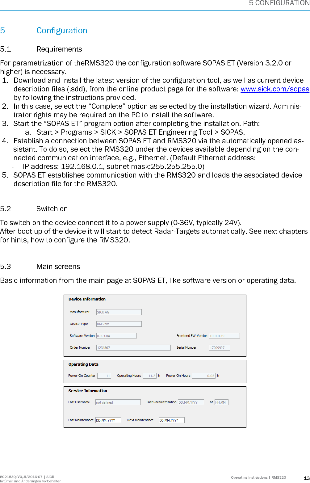
![1 ABOUT THIS DOCUMENT 4 Operating instructions | RMS320 8021530/V0,.5/2016-07 | SICK Irrtümer und Änderungen vorbehalten 1 About this Document Information regarding the operating instructions These operating instructions provide important information on how to handle Radar Measurement Systems from SICK AG. Prerequisites for working safely are: - Adherence to all the specified safety instructions and guidelines. - Complying with any local work safety regulations and general safety specifications applicable to the use of the Radar Measurement System These operating instructions are intended for specialists and electricians. Important Read these instructions carefully before starting any work on the device to familiarize yourself with the RMS320 Radar Measurement System and its functions. The operating instructions are considered a part of the device and must be kept in an accessible location in the immediate vicinity of the device at all times, optimally in printed format. Should the device be passed on to a third party, these operating instructions should be handed over with it. These operating instructions do not provide information on operating the machine in which the Radar Measure-ment System is integrated. For information about this, refer to the operating instructions of the respective ma-chine. 1.1 Scope These operating instructions are designed to address the technical personnel in regards to safe mounting, electri-cal installation, commissioning and configuration and maintenance of the following laser measurement sensor variants. A step-by-step approach is taken for all tasks. 1.2 Depth of information These operating instructions contain the following information on the RMS320. Product description Transport and storage Mounting Electrical installation Commissioning and configuration Maintenance Troubleshooting Technical data In addition, an online help is available in the SOPAS ET configuration software supplied; this help provides infor-mation on the usage of the software user interface, as well as on the configuration of the RMS320. You will find a detailed description of the different telegrams for the RMS320 in the document “Telegram Listing Radar Measurement System”, part no.: 8021531, English version. You will find further information on the LMS5xx, its accessories as well as documents on the online product page [www.sick.com/rms320].](https://usermanual.wiki/Sick/RMS320/User-Guide-3452553-Page-4.png)