Sick RMS320 Radar transceiver for movement detection User Manual Ger tefamilie
Sick AG Radar transceiver for movement detection Ger tefamilie
Sick >
user manual

Radar measurement sensor
O P E R A T I N G I N S T R U C T I O NS
RMS320

8021530/V0,.5/2016-07 | SICK
Irrtümer und Änderungen vorbehalten
Operating instructions | RMS320
2
Described product
RMS320
Manufacturer
SICK AG
Erwin-Sick-Str. 1
79183 Waldkirch
Germany
Copyright
This work is protected by copyright. Any rights derived from the copyright shall be re-
served for SICK AG. Reproducing of this document or parts of this document is only
permissible within the limits of the legal determination of Copyright Law. Any modifica-
tion, expurgation or translation of this document is prohibited without the express writ-
ten permission of SICK AG.
© SICK AG. All rights reserved.
Original document
This document is an original document of SICK AG.

TABLE OF CONTENTS
8021530/V0,.5/2016-07 | SICK
Irrtümer und Änderungen vorbehalten
Operating instructions | RMS320
3
Table of contents
1 About this Document .............................................................................. 4
1.1 Scope .............................................................................................................. 4
1.2 Depth of information ...................................................................................... 4
2 For your safety ......................................................................................... 5
2.1 General safety notes and protective measures ........................................... 5
2.2 Warning notices on device ............................................................................. 6
2.3 Intended use of device................................................................................... 6
2.4 Non-intended use ........................................................................................... 6
2.5 Authorized personnel ..................................................................................... 7
3 Product description................................................................................. 8
3.1 Delivery ........................................................................................................... 8
4 Electrical Installation .............................................................................. 9
4.1 Connectivity .................................................................................................... 9
5 Configuration ......................................................................................... 13
5.1 Requirements ............................................................................................... 13
5.2 Switch on ...................................................................................................... 13
5.3 Main screens ................................................................................................ 13
5.4 System configuration ................................................................................... 14
5.5 Service .......................................................................................................... 14
6 Startup and operation .......................................................................... 15
6.1 Status indicators ................................................................................... 16
7 Troubleshooting .................................................................................... 17
7.1 Safety ............................................................................................................ 17
7.2 Monitoring error and malfunction indications (LED) .................................. 17
7.3 Troubleshooting and rectification table ...................................................... 17
8 Technical data ....................................................................................... 18
8.1 Dimensional Drawing ................................................................................... 18
8.2 Technical Data .............................................................................................. 19
9 Accessories ............................................................................................ 21
9.1 Weather hood ............................................................................................... 21
9.2 Mounting ....................................................................................................... 22
10 Appendix................................................................................................. 23
10.1 Conformities ................................................................................................. 23
10.2 Approvals ...................................................................................................... 23
10.3 Lizenzen ........................................................................................................ 24

1 ABOUT THIS DOCUMENT
4
Operating instructions | RMS320
8021530/V0,.5/2016-07 | SICK
Irrtümer und Änderungen vorbehalten
1 About this Document
Information regarding the operating instructions
These operating instructions provide important information on how to handle Radar Measurement Systems from
SICK AG.
Prerequisites for working safely are:
- Adherence to all the specified safety instructions and guidelines.
- Complying with any local work safety regulations and general safety specifications applicable to the use of
the Radar Measurement System
These operating instructions are intended for specialists and electricians.
Important Read these instructions carefully before starting any work on the device to familiarize yourself with the
RMS320 Radar Measurement System and its functions.
The operating instructions are considered a part of the device and must be kept in an accessible location in the
immediate vicinity of the device at all times, optimally in printed format. Should the device be passed on to a third
party, these operating instructions should be handed over with it.
These operating instructions do not provide information on operating the machine in which the Radar Measure-
ment System is integrated. For information about this, refer to the operating instructions of the respective ma-
chine.
1.1 Scope
These operating instructions are designed to address the technical personnel in regards to safe mounting, electri-
cal installation, commissioning and configuration and maintenance of the following laser measurement sensor
variants.
A step-by-step approach is taken for all tasks.
1.2 Depth of information
These operating instructions contain the following information on the RMS320.
Product description
Transport and storage
Mounting
Electrical installation
Commissioning and configuration
Maintenance
Troubleshooting
Technical data
In addition, an online help is available in the SOPAS ET configuration software supplied; this help provides infor-
mation on the usage of the software user interface, as well as on the configuration of the RMS320.
You will find a detailed description of the different telegrams for the RMS320 in the document “Telegram Listing
Radar Measurement System”, part no.: 8021531, English version.
You will find further information on the LMS5xx, its accessories as well as documents on the
online product page [www.sick.com/rms320].

2 FOR YOUR SAFETY
8021530/V0,.5/2016-07 | SICK
Irrtümer und Änderungen vorbehalten
Operating instructions | RMS320
5
2 For your safety
2.1 General safety notes and protective measures
Please observe the following items in order to ensure the correct and safe use of the RMS320.
The notices in these operating instructions (e.g. on use, mounting, installation or integration into the exist-
ing machine controller) must be observed.
When operating the RMS320, the national, local and statutory rules and regulations must be observed.
National/international rules and regulations apply to the installation, commissioning, use and periodic
technical inspections of the MRS320, in particular
o the work safety regulations/safety rules
o other relevant health and safety regulations.
Manufacturers and operators of the machine/system on which the RMS320 is installed are responsible
for obtaining and observing all applicable safety regulations and rules.
The tests must be carried out by specialist personnel or specially qualified and authorized personnel and
must be recorded and documented to ensure that the tests can be reconstructed and retraced at any
time.
The operating instructions must be made available to the operator of the system where the RMS320 is
used. The operator of the system is to be instructed in the use of the device by specialist personnel and
must be instructed to read the operating instructions.
The RMS320 is not a device for the protection of people in the context of the related safety standards for
machinery.
2.1.1 Quick stop and quick restart
2.1.1.1 Switch the RMS320 off
Switch off the voltage supply (power supply) for the RMS320
The RMS320 retains parameters stored in the internal, non-volatile memory. Measured values in the memory are
lost.
2.1.1.2 Switch the RMS320 on
Switch on the voltage supply (power supply) for the RMS320
The RMS320 restarts operation with the last saved parameters.
2.1.2 RADAR
General/Intended use
The RMS320 sensor is designed for both indoor and outdoor area monitoring. Within a defined detection area, the
sensor detects static and moving objects, and triggers a I/O signal upon detection of a corresponding object. Dis-
tance zones can be defined and have various functions assigned to them.
The RMS320 is designed for detection of objects within the operating range. In case an object has been detected
the integrated I/O will provide a signal. Additionally the resting time of the objects, the speed and direction of
movement within the detection range will be calculated and provided via the data telegram.
The RMS320 and the SICK firmware is designed to visualize and control objects within the operating range.
All object data can be provided via Ethernet. The RMS320 is prepared to provide the object data also via the CAN
protocol.
To operate the RMS320 the software SOPAS ET by SICK AG needs to be used.
A more detailed description of the software and parameters are listed in this document.

2 FOR YOUR SAFETY
6
Operating instructions | RMS320
8021530/V0,.5/2016-07 | SICK
Irrtümer und Änderungen vorbehalten
2.1.2.1 Health hazard as a result of high-frequency electromagnetic radiation!
The RMS30 is designed for operation in accordance with ETSI EN 300 440. During operation the human exposure
regulations covered by EN 62311 must be observed.
In order to limit human exposure to electromagnetic fields, suitable safety distances must be maintained during
both short-term and long-term work in the radiation range of the antenna(s).
Minimum distances to be maintained between the antenna and the human body during continuous transmission:
20 cm.
The RMS320 satisfies the limit values of the FCC for exposure to radiation in an uncontrolled environment.
For country-specific particulars to consider when operating the RMS320, see chapter “Operational restrictions” in
this document.
2.2 Warning notices on device
Before setting the RMS320 into operation please consider the warning instructions placed on the back side of the
RMS320 housing and the safety notes in this document.
2.3 Intended use of device
Notice:
The RMS320 sensor is intended for use in industrial environments. It is not intended for safety applications e.g.
protection of humans.
The RMS320 is used to determine objects within the detection zone according to the technical datasheet.
After fitting and setting into operation the RMS320 continuously detects the area of the detection zone. Once
objects will be detected the RMS320 provides the actual status via the I/O outputs and/or the data output proto-
col. These signals will be provided as long as the object is detected inside of the detection zone.
Important:
In case of any other usage as well as in case of modifications to the RMS320, e.g. due to opening the housing
during mounting and electrical installation, or to the SICK software, any claims against SICK AG under the warran-
ty will be rendered void.
Notice:
The RMS320 is only allowed to be operated in the ambient temperature range allowed as described in the tech-
nical data sheet.
2.4 Non-intended use
The RMS320 is not designed for safety applications, detection of humans and safety applications.

2 FOR YOUR SAFETY
8021530/V0,.5/2016-07 | SICK
Irrtümer und Änderungen vorbehalten
Operating instructions | RMS320
7
2.5 Authorized personnel
The RMS320 must only be installed, commissioned and serviced by adequately qualified personnel.
Repairs to the RMS320 are only allowed to be undertaken by trained and authorized service personnel from SICK
AG.
The following qualifications are necessary for the various tasks:
Activities
Qualification
Mounting and Maintenance
Basic technical training
Knowledge of the current safety regulations in the workplace
Electrical installation and
replacement
Practical electrical training
Knowledge of current safety regulations
Knowledge on the use and operations of devices in the re-
lated application (e.g. cranes, assembly systems, special ve-
hicles)
Commissioning, operation
and configuration
Knowledge on the use and operation of the devices in the re-
lated application (e.g. cranes, assembly systems, special ve-
hicles)
Knowledge on the software and hardware environment in
the related environment (e.g. cranes, assembly systems,
special vehicles)
Basic knowledge of the Windows operating system
Basic knowledge of the data transmission

3 PRODUCT DESCRIPTION
8
Operating instructions | RMS320
8021530/V0,.5/2016-07 | SICK
Irrtümer und Änderungen vorbehalten
3 Product description
This chapter provides information on the special features and properties of the RMS320. It
describes the construction and the operating principle of the device, in particular the different
operating modes.
Read this chapter carefully before commissioning the RMS320 in order to familiarize yourself
with the device and its functions.
3.1 Delivery
Scope of Delivery:
Quantity
Component
Comment
1
RMS320
In the version ordered (regional assign-
ment).
Electrical connections fitted with protective
caps or plugs.
Source for obtaining additional information
Additional information about the RMS320 and its optional accessories can be found in the fol-
lowing places:
Product web page for the RMS320 at: www.sick.com/rms320
Detailed technical specifications (online data sheet)
Technical information (supplementary information on telegrams)
These operating instructions are available in German, English and other languages if re-
quired.
Dimensional drawing and 3D CAD dimension models in various electronic formats
EC declaration of conformity
SOPAS configuration software updates
Support is also available from your sales partner: www.sick.com/worldwide .

4 ELECTRICAL INSTALLATION
8021530/V0,.5/2016-07 | SICK
Irrtümer und Änderungen vorbehalten
Operating instructions | RMS320
9
4 Electrical Installation
The electrical installation must only be performed by electrically qualified persons.
Standard safety requirements must be met when working on electrical systems.
Electrical connections between the RMS320 and other devices may only be created or disconnected
when there is no power to the system. Otherwise, the devices may be damaged.
When using connecting or extension cables with an open end, make sure that bare wire ends are not
touching (risk of short-circuit when the supply voltage is switched on). Wires must be appropriately insu-
lated from each other.
Wire cross-sections in the supply cable from the customer's power system must be designed in accord-
ance with the applicable standards.
All circuits connected to the RMS320 must be designed as SELV circuits.
Supply voltage
9V to 36 V DC supply voltage; 2A protection at the start of the feeding supply circuit.
The voltage supply or power supply unit must satisfy SELV requirements in accordance with the currently
applicable EN 60950-1. (SELV = Safety Extra Low Voltage).
The voltage supply via a power supply unit must be capable of buffering a brief power failure of 20 ms.
NOTE
Risk of damage to the RMS320 due to possible short-circuit!
The supply voltage input for the RMS320 is designed with internal circuit protection to provide reverse polarity
protection. The internal functional earth, which also corresponds to the negative pole of the supply voltage for the
RMS320, is connected directly to the metal housing of the RMS320.
WARNING
Risk of injury and damage caused by electrical current!
The RMS320 is designed to be operated in a system with professional grounding of all connected devices and
mounting surfaces to the same ground potential. Incorrect grounding of the RMS320 can result in equipotential
bonding currents between the RMS320 and other grounded devices in the system. This can lead to hazardous
voltages being applied to the metal housing, cause devices to malfunction or sustain irreparable damage, and
damage the cable shield as a result of a heat increase, causing cables to set alight.
Ensure that the ground potential is the same at all grounding points. If the cable insulation is damaged, discon-
nect the voltage supply immediately and exchange the damaged cable.
4.1 Connectivity
Installation of the RMS320:
1. Connect the 5-pin M12 male Connector (“Power/IO”) via a suitable cable (e.g., No. 6049451, 1.5 m)
2. Opt. connect the 8-pin M12 male Connector (“CAN/IO”) via a suitable cable (e.g., No. 6034415, 5 m)
3. Depending on the length of the connecting cable, supply the RMS320 with 9V to 36V DC
4. After successful initialization, the “Device Ready” LED lights up green
0
10
Operating instructions | RMS320
8021530/V0,.5/2016-07 | SICK
Irrtümer und Änderungen vorbehalten
Notice:
Only authorized personnel are allowed to perform the electrical installation work.
Only make and disconnect electrical connections when the device is electrically isolated.
Select and implement wire cross-sections and their correct fuse protection as per the applicable stand-
ards.
Do not open the housing.
Observe the current safety regulations when working on electrical systems.
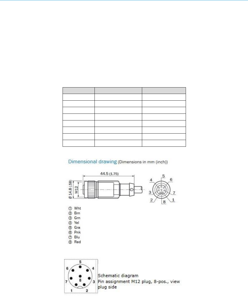
M12 8p A-coded
Pin
Function
color
1
CAN H
Wht
2
CAN L
Brn
3
IN2
Grn
4
GND IN1/2
Yel
5
OUT2
Gra
6
OUT3
Pnk
7
GND
Blu
8
OUT4
Red
0
8021530/V0,.5/2016-07 | SICK
Irrtümer und Änderungen vorbehalten
Operating instructions | RMS320
11
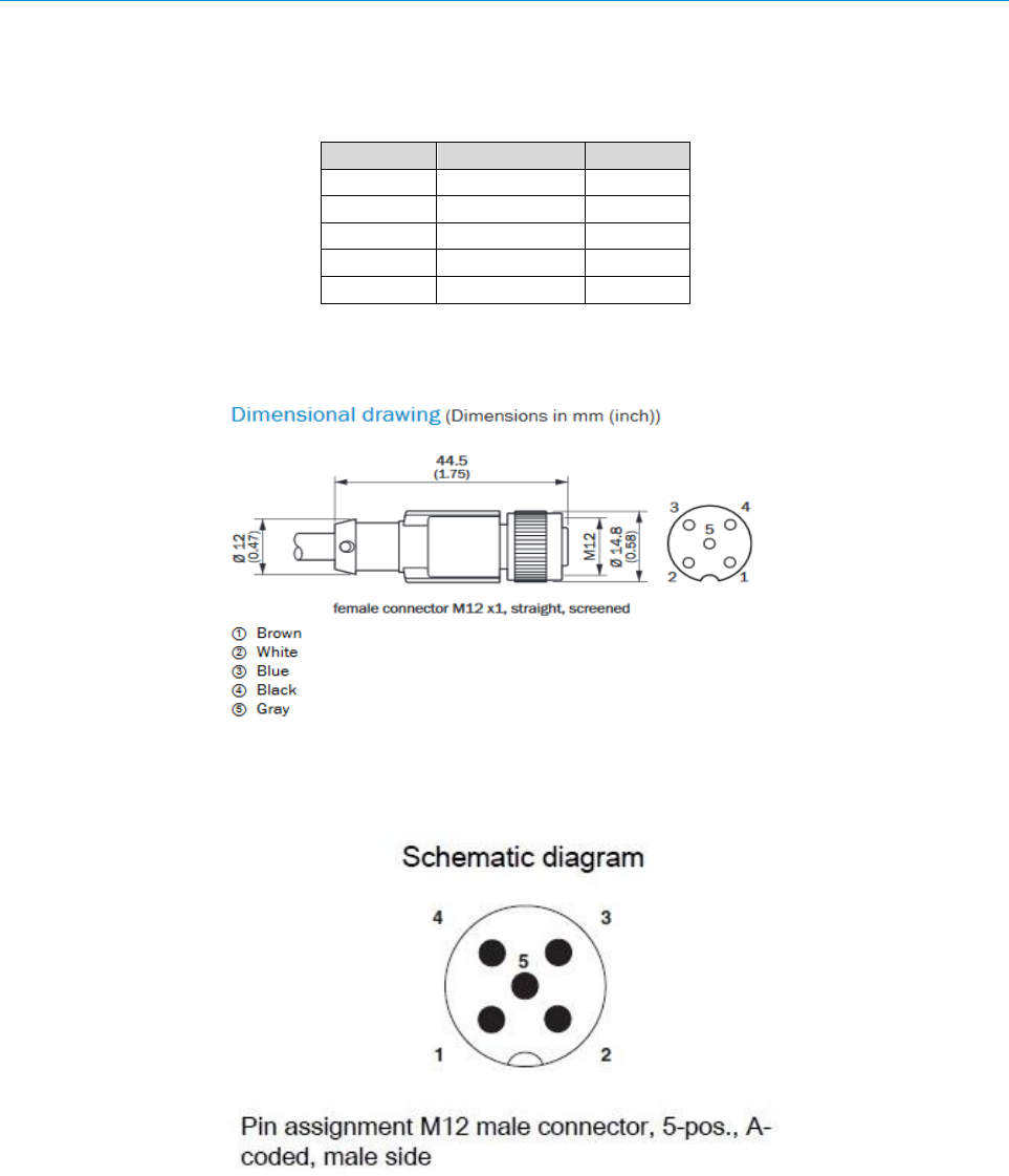
M12 5p A-coded
Pin
Function
color
1
VS 9..36V
Brn
2
IN1
Wht
3
GND
Blu
4
OUT1
Blk
5
GND IN1/2
Gra
0
12
Operating instructions | RMS320
8021530/V0,.5/2016-07 | SICK
Irrtümer und Änderungen vorbehalten
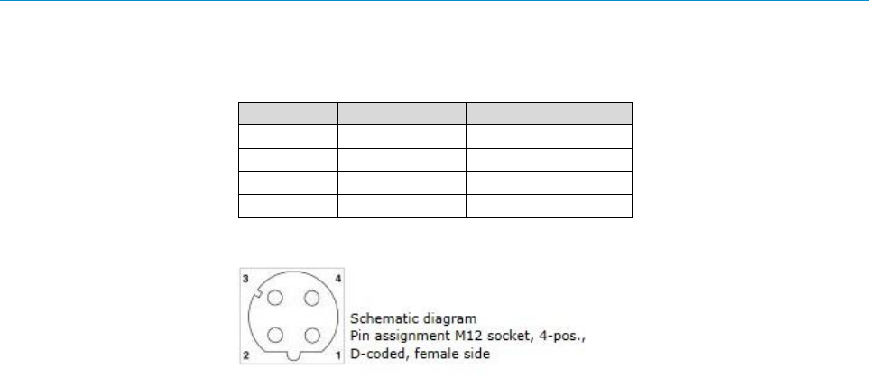
M12 4p D-coded
Pin
Signals
Function
1
TD+
Transmit_Data +
2
RD+
Receive_Data +
3
TD-
Transmit_Data –
4
RD-
Receive_Data +
5 CONFIGURATION
8021530/V0,.5/2016-07 | SICK
Irrtümer und Änderungen vorbehalten
Operating instructions | RMS320
13
5 Configuration
5.1 Requirements
For parametrization of theRMS320 the configuration software SOPAS ET (Version 3.2.0 or
higher) is necessary.
1. Download and install the latest version of the configuration tool, as well as current device
description files (.sdd), from the online product page for the software: www.sick.com/sopas
by following the instructions provided.
2. In this case, select the “Complete” option as selected by the installation wizard. Adminis-
trator rights may be required on the PC to install the software.
3. Start the “SOPAS ET” program option after completing the installation. Path:
a. Start > Programs > SICK > SOPAS ET Engineering Tool > SOPAS.
4. Establish a connection between SOPAS ET and RMS320 via the automatically opened as-
sistant. To do so, select the RMS320 under the devices available depending on the con-
nected communication interface, e.g., Ethernet. (Default Ethernet address:
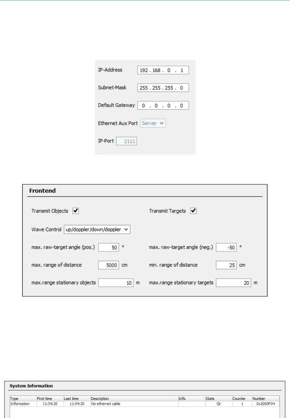
- IP address: 192.168.0.1, subnet mask:255.255.255.0)
5. SOPAS ET establishes communication with the RMS320 and loads the associated device
description file for the RMS320.
5.2 Switch on
To switch on the device connect it to a power supply (0-36V, typically 24V).
After boot up of the device it will start to detect Radar-Targets automatically. See next chapters
for hints, how to configure the RMS320.
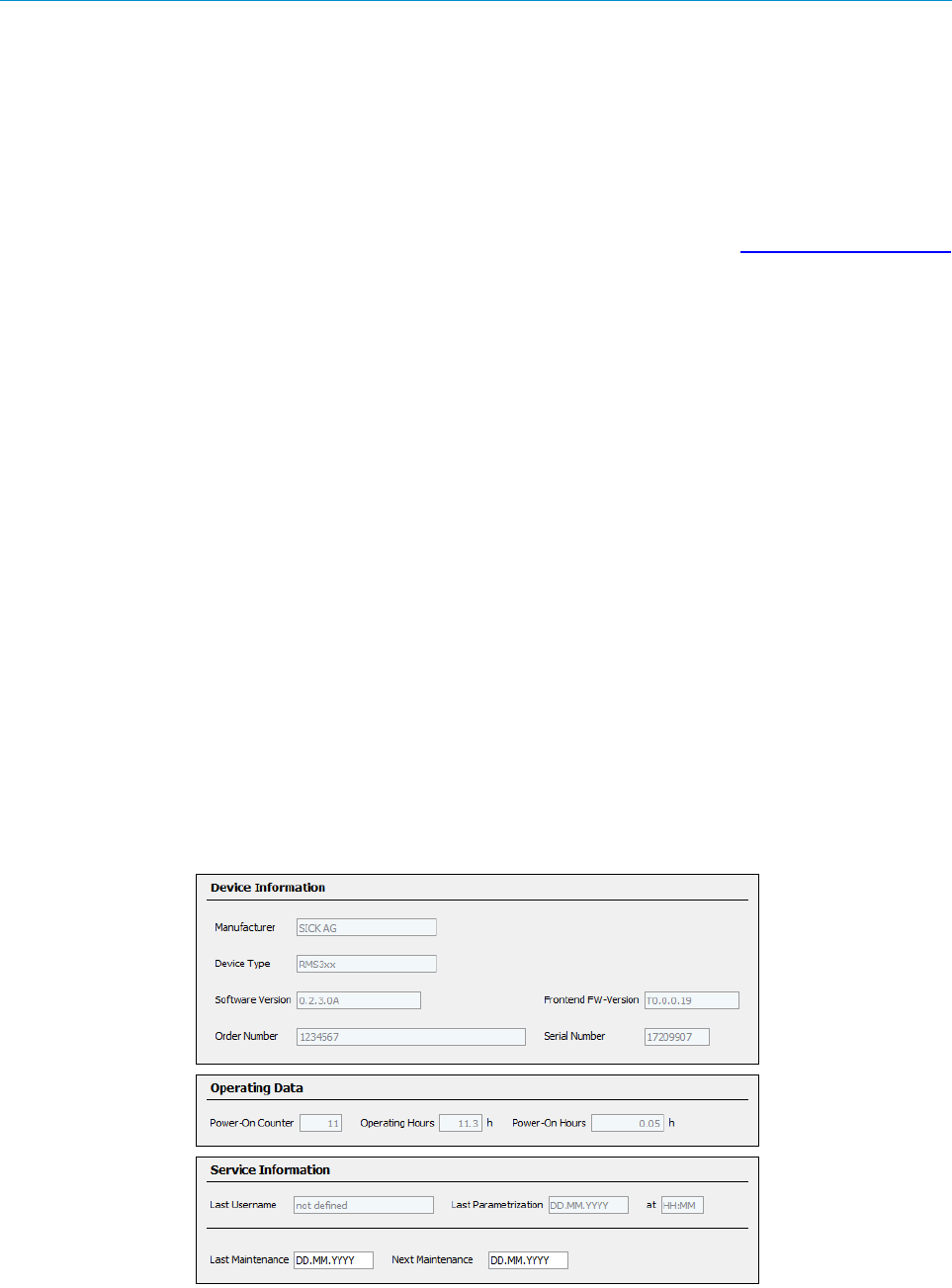
5.3 Main screens
Basic information from the main page at SOPAS ET, like software version or operating data.
5 CONFIGURATION
14
Operating instructions | RMS320
8021530/V0,.5/2016-07 | SICK
Irrtümer und Änderungen vorbehalten
5.4 System configuration
To change Ethernet configuration see “Ethernet” at the right side of configuration tool.
5.5 Service
To see system information, choose page “system-status”.
This page will appear if you are logged in as “Service”. The system information table provides
information of three different levels: Information, Warning and Error.
In case of troubles use this page to get some more information about the radar system.

6 STARTUP AND OPERATION
8021530/V0,.5/2016-07 | SICK
Irrtümer und Änderungen vorbehalten
Operating instructions | RMS320
15
6 Startup and operation
The RMS320 operates fully automatically in normal operation without the intervention of an
operator.
The interactive configuration is carried out using the provided SOPAS ET configuration soft-
ware. The software used for this purpose runs on a PC with the operating system Windows that
is connected to the RMS320 via one of the interfaces.
Use the graphic scan view in SOPAS ET to verify the generated measured values and to verify
the measurement area online.
During this process, note that SOPAS ET cannot display the data in real-time and therefore
does not display all measured values.
6.1 STATUS INDICATORS
16
Operating instructions | RMS320
8021530/V0,.5/2016-07 | SICK
Irrtümer und Änderungen vorbehalten
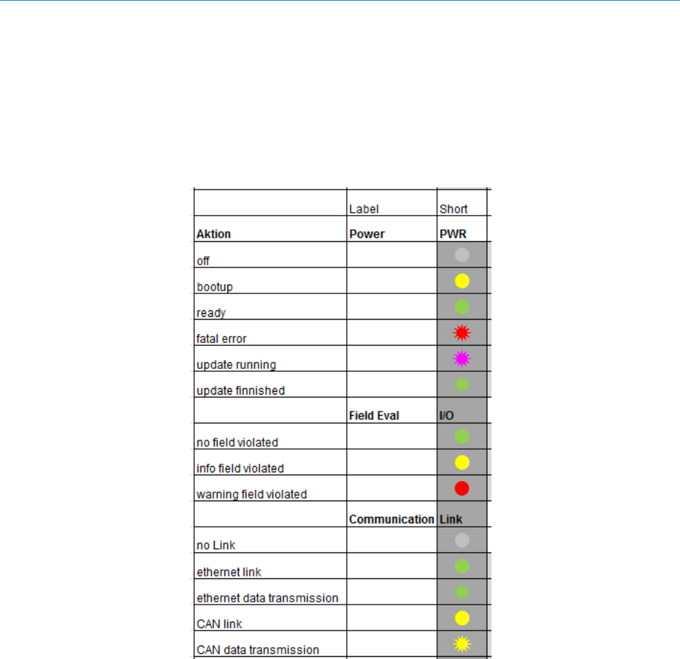
6.1 Status indicators
The LEDs signal the operational status of the RMS320.
The RMS320 has three LEDs. These visually signal the actual operational status.
The LEDs are mounted and visible on the front side of the device on the RMS320.
The following table shows the function of the LEDs:

7 TROUBLESHOOTING
8021530/V0,.5/2016-07 | SICK
Irrtümer und Änderungen vorbehalten
Operating instructions | RMS320
17
7 Troubleshooting
Important: Claims under the warranty rendered void!
The housing screws of the RMS320 are sealed. Claims under the warranty against SICK AG will be rendered void if
the seals are damaged or the device opened. The housing is only allowed to be opened by authorized service per-
sonnel.
This chapter describes how to identify and rectify errors and malfunctions during the operation of the RMS320.
7.1 Safety
Warning: Cease operation if the cause of the malfunction has not been clearly identified!
Stop the machine/system if you cannot clearly identify or allocate the error and if you cannot safely rectify the
malfunction.
7.2 Monitoring error and malfunction indications (LED)
The RMS320 monitors itself in operation:
After switching on the supply voltage the RMS320 runs through a self-test prior to initialization (loading
the parameter set and initialization of the device functions); during this self-test the device checks im-
portant hardware components.
During operation the RMS320 continuously monitors the function.
If the RMS320 detects a device error, it indicates this situation using the LEDs (see above).
See also chapter “Service”
7.3 Troubleshooting and rectification table
Fault
Possible cause
Solution
1. All LEDs are off
No power-supply connected
Connect to power supply
2. PWR red flashing
Fatal Error;
No functional radar measurement
Contact service
3. I/O red permanent
Warning field violated
Object detected
4. SOPAS ET cannot
communicate with
RMS320
Bad connection
Check connection
5. No measurements in
the detection zone
No objects visible
Check detection zone orientation
6. No I/O data output
No detection signals
Wrong setting
Bad connection
Check detection zone orientation,
settings and connection
7. RMS320 is not trans-
mitting data via Ether-
net / CAN
Wrong settings
No connection;
Check settings and connection
8 TECHNICAL DATA
18
Operating instructions | RMS320
8021530/V0,.5/2016-07 | SICK
Irrtümer und Änderungen vorbehalten
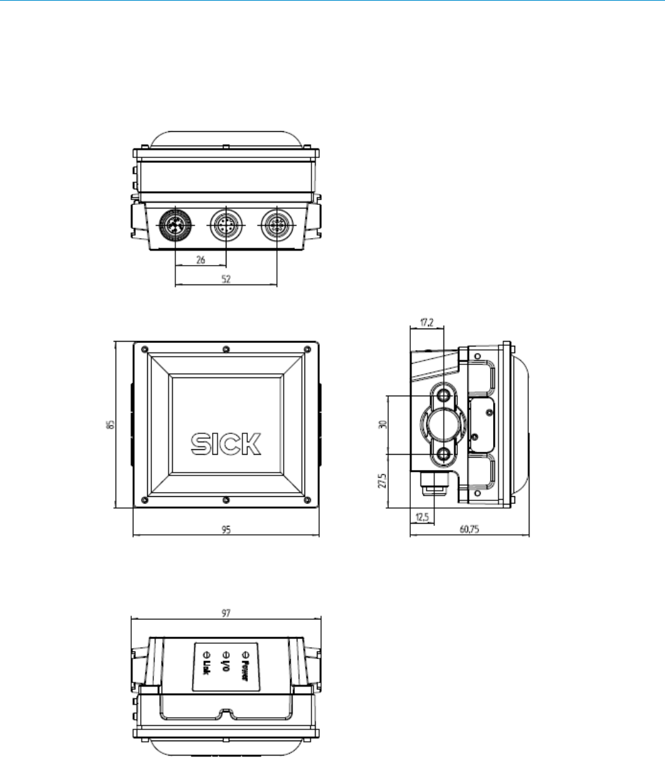
8 Technical data
8.1 Dimensional Drawing

8 TECHNICAL DATA
8021530/V0,.5/2016-07 | SICK
Irrtümer und Änderungen vorbehalten
Operating instructions | RMS320
19
8.2 Technical Data
Region assignment
Europe, USA, Canada, Japan
Frequency band
24.05 … 24.25 GHz
Transmitting power
+12,7 dBm e.i.r.p.
Max. Range on 1m² RCS (*2)
Max. Range on 10m² RCS (*3)
Min. Range
20 m (Typical values)
45 m (Typical values)
1 m (Presence detection below is available)
CAN
CAN (CANopen®), 20 kBit/s ... 500 KBit/s, not terminated
Ethernet
Host TCP/IP, Aux TCP/IP for configuration 10/100Mbit/s
Digital switching inputs
2 x Galvanically isolated from the supply voltage
Ue = max. 36 V, Ie = max. 5 mA
Opto decoupled, reverse polarity protected, debouncing time
adjustable
Digital switching outputs
4 x Galvanically not separated from the supply voltage
PNP / NPN / PP configurable
Ua = UV – 1,5 V, Ia ≤ 100 mA ( typical ).
Short Circuit Protection, temperature protected
Elektrical
connections
• 1 x plug, M12, 8-pol., A-coded
• 1 x plug, M12, 5-pol., A-coded
• 1 x Connector female , Ethernet, 4 - pol., D-coded
Optical
indicators
• 1 x RGB-LED ( Power ) across from M12, 5-pol.
• 1 x RGB-LED ( Application ) across from M12, 8-pol.
• 1 x RGB-LED ( Ethernet-link/ CAN ) across from
M12, 4-pol ( LED not configurable )
Supply voltage
SELV according to EN 60950-1.
Only RMS320 FCC: SELV (EN 60950-1:2006-04)
and LPS (EN 60950-1:2006-04) or Class 2 (UL 1310).
DC 9 V ... 36 V during operation without SICK Connection
Module. Each using a SICK line.
See chapter „: Electrical Installation“
Power consumption
At full transmitting power:
Max. 21W ( with a typical loading of the 4 switching
Outputs of 100 mA each and a 36V DC supply voltage)
Typically < 6 W ( with no loading of switching outputs )
Housing/weight
Aluminum / approx.. 500g
Safety
EN 60950-1: 2006-04/A11: 2009-03/
A1: 2010-03/A12: 2011-02
Electrical
Protection class
III (EN 61140: 2006-08)
Enclosure rating
IP 67 (EN 60529: 1991-10/A2: 2000-02)
Radio approval
Europe: FINAL DRAFT ETSI EN 300 440 V2.1.1
USA: FCC Part 15.249/15.107/15.109
Canada: RSS310, ICES 003
Japan: ARIB STD-T73
EMC
ETSI EN 301489-1 V2.1.1 ( 2017/2 ), Draft ETSI
EN 301489-3 V2.1.1 und EN 61000 - 6 - 2
Vibration resistance
Shock resistance
EN 60068-2-6: 2008-02
EN 60068-2-27: 2009-05
Ambient temperature range
Operation: - 40 °C ... +65 °C
Storage: - 40 °C ... +85 °C
Relative humidity
0 % ... 90 %, non condensing
Approvals
CE
Clock
NTP-network-time protocol, no internal clock

8 TECHNICAL DATA
20
Operating instructions | RMS320
8021530/V0,.5/2016-07 | SICK
Irrtümer und Änderungen vorbehalten
1) UL-certified in case the UL-Logo is placed on the device
2) 1m² RCS typical to pedestrian
3) 10m² RCS typical to passenger car
Further technical data: See online datasheet at www.sick.com/RMS320
Warnings
NOTE
Operational restrictions!
The RMS320 is approved for operation in the regions according to the rows "Region assignment" and
"Radio approval" in the table above. When operating in other regions protected frequencies can be dis-
turbed.
- Only use the RMS320 in regions for which it has been approved.
- When reselling the RMS320, inform the buyer of the regional assignment.
9 ACCESSORIES
8021530/V0,.5/2016-07 | SICK
Irrtümer und Änderungen vorbehalten
Operating instructions | RMS320
21
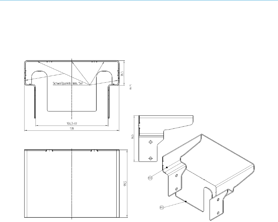
9 Accessories
9.1 Weather hood
Dimensional Drawing:
9 ACCESSORIES
22
Operating instructions | RMS320
8021530/V0,.5/2016-07 | SICK
Irrtümer und Änderungen vorbehalten
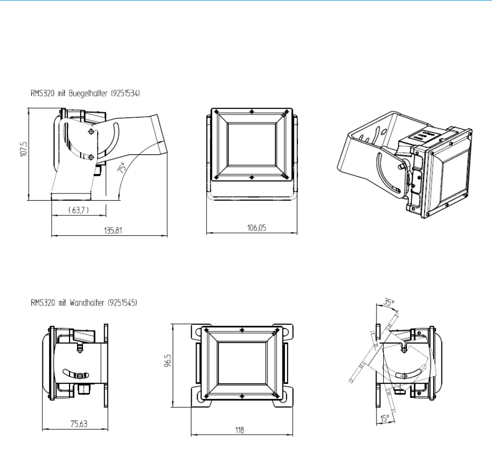
9.2 Mounting
RMS320 with angle mount:
RMS320 with wall frame:

10 APPENDIX
8021530/V0,.5/2016-07 | SICK
Irrtümer und Änderungen vorbehalten
Operating instructions | RMS320
23
10 Appendix
10.1 Conformities
10.1.1 Europe
SIMPLIFIED EU DECLARATION OF CONFORMITY
Hereby, SICK AG declares that the radio equipment type RMS320 is in
compliance with Directive 2014/53/EU.
The full text of the EU declaration of conformity is available at the following internet address:
www.sick.com/RMS320
10.2 Approvals
10.2.1 USA
FCC ID: WRMRMS320
(1) This device complies with part 15 of the FCC Rules. Operation is subject to the following two conditions:(1)
This device may not cause harmful interference, and (2) this device must accept any interference received,
including interference that may cause undesired operation.
(2) Changes or modifications not expressly approved by the party responsible for compliance could void the
user's authority to operate the equipment.
(3) Note: This equipment has been tested and found to comply with the limits for a Class A digital device,
pursuant to part 15 of the FCC Rules. These limits are designed to provide reasonable protection against
harmful interference when the equipment is operated in a commercial environment. This equipment generates,
uses, and can radiate radio frequency energy and, if not installed and used in accordance with the instruction
manual, may cause harmful interference to radio communications. Operation of this equipment in a residential
area is likely to cause harmful interference in which case the user will be required to correct the interference at
his own expense.
(4) To comply with FCC part 15 rules in the United States, the system must be professionally installed to ensure
compliance with the Part 15 certification.
(5) It is the responsibility of the operator and professional installer to ensure that only certified systems are
deployed in the United States. The use of the system in any other combination (such as co-located antennas
transmitting the same information) is expressly forbidden.
(6) This equipment complies with FCC radiation exposure limits set forth for an uncontrolled environment. This
equipment should be installed and operated with minimum distance 30 cm between the radiator and your body.
10.2.2 Canada
This device complies with Industry Canada's RSS-310. Operation is subject to the condition that this device must
not cause harmful interference and must accept any interference, including interference that may cause unde-
sired operation of the device.
Cet appareil est conforme au CNR-310 d'Industrie Canada. Son exploitation est autorisée à condition que l'appa-
reil ne produise pas de brouillage préjudiciable et qu'il accepte tout brouillage, même celui susceptible d'en com-
promettre le fonctionnement.

10 APPENDIX
24
Operating instructions | RMS320
8021530/V0,.5/2016-07 | SICK
Irrtümer und Änderungen vorbehalten
10.2.3 Japan
10.3 Licenses
SICK uses open-source software. This software is licensed by the rights holders using
the following licenses among others: the free licenses GNU General Public License (GPL
Version2, GPL Version3) and GNU Lesser General Public License (LGPL), the MIT li-
cense, zLib license, and the licenses derived from the BSD license.
This program is provided for general use, but WITHOUT ANY WARRANTY OF ANY KIND.
This warranty disclaimer also extends to the implicit assurance of marketability or suit-
ability of the program for a particular purpose.
More details can be found in the GNU General Public License. View the complete li-
cense texts here: www.sick.com/licensetexts. Printed copies of the license texts are
also available on request.

10 APPENDIX
8021530/V0,.5/2016-07 | SICK
Irrtümer und Änderungen vorbehalten
Operating instructions | RMS320
25