Sick W16 W.16-family User Manual WLG16 Bluetooth 8022197
SICK AG W.16-family WLG16 Bluetooth 8022197
Sick >
User Manual
OPERATING INSTRUCTIONS
WLG16 Bluetooth®

Described product
WLG16 - Bluetooth®
Manufacturer
SICK AG
Erwin-Sick-Str. 1
79183 Waldkirch
Germany
Legal information
This work is protected by copyright. Any rights derived from the copyright shall be
reserved for SICK AG. Reproduction of this document or parts of this document is only
permissible within the limits of the legal determination of Copyright Law. Any modifica‐
tion, abridgment or translation of this document is prohibited without the express writ‐
ten permission of SICK AG.
The trademarks stated in this document are the property of their respective owner.
© SICK AG. All rights reserved.
Original document
This document is an original document of SICK AG.
28022197 | SICK
Subject to change without notice

Contents
1 Safety information............................................................................ 4
1.1 General safety notes................................................................................ 4
1.2 Notes on UL approval............................................................................... 4
2 Intended use...................................................................................... 4
3 Operating and status indicators...................................................... 4
4 Mounting............................................................................................. 5
5 Electrical installation........................................................................ 5
6 Commissioning.................................................................................. 8
7 Troubleshooting................................................................................. 12
8 Disassembly and disposal............................................................... 12
9 Maintenance...................................................................................... 12
10 Approvals............................................................................................ 13
10.1 Bluetooth® approvals............................................................................... 13
11 Technical data.................................................................................... 13
11.1 General technical data............................................................................. 13
11.2 Bluetooth technical data®....................................................................... 14
CONTENTS
8022197 | SICK
Subject to change without notice 3

1 Safety information
1.1 General safety notes
■Read the operating instructions before commissioning.
■
Connection, mounting, and setting may only be performed by trained spe‐
cialists.
■Not a safety component in accordance with the EU Machinery Directive.
■When commissioning, protect the device from moisture and contamination.
■These operating instructions contain information required during the life cycle of
the sensor.
1.2 Notes on UL approval
The device must be supplied by a limited voltage / limited current circuit or is intended
to be connected to a Class 2 source of supply. In case of a limited voltage / limited cur‐
rent circuit the device shall be supplied from an isolating transformer having a sec‐
ondary overcurrent protective device that complies with UL 248 to be installed in the
field rated either:
a) max 5 amps for voltages 0~20 V (0~28.3 V peak), or
b) 100/Vp for voltages of 20~30 V (28.3~42.4 V peak).
UL Environmental Rating: Enclosure type 1
2 Intended use
The WLG16 is an opto-electronic photoelectric retro-reflective sensor (referred to as
“sensor” in the following) for the optical, non-contact detection of objects, animals, and
persons. A reflector is required for this product to function. If the product is used for any
other purpose or modified in any way, any warranty claim against SICK AG shall become
void.
Photoelectric retro-reflective sensor with optional add-on for detecting transparent
objects (WLG-xx).
3 Operating and status indicators
1 SAFETY INFORMATION
48022197 | SICK
Subject to change without notice
20
Ø 12,9
Ø 4,1
39,9
55,4
45,5 5
42
29,9
6
3
6,5
15
27,8
7,7
7,8
7,2
35,5
4,1
8,3
55,7
3
2
34,5
1
4
65
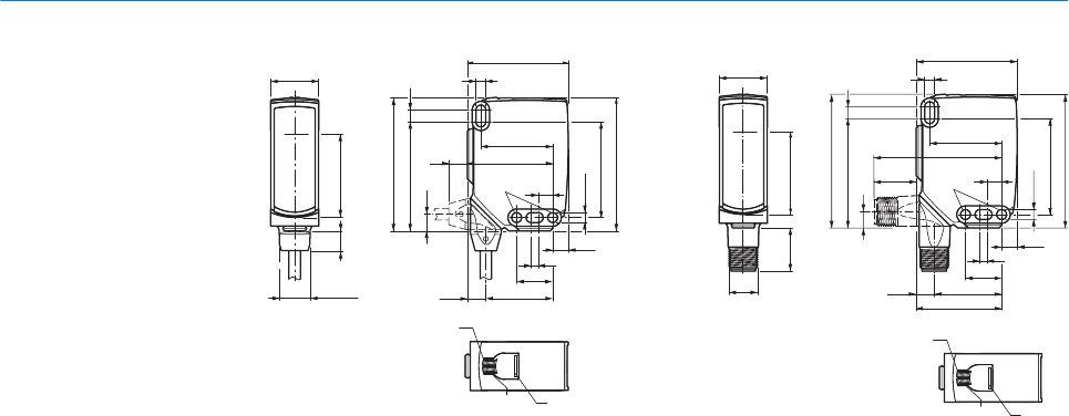
Figure 1: Dimensional drawing 1, cable
1Center of optical axis
2Fixing hole, Ø 4.1 mm
3Connection
4LED indicator green: Supply voltage
active
5LED indicator yellow: Status of
received light beam
6BluePilot blue: Alignment aid
20
M12
18
Ø 4,1
39,9
55,4
55,7
45,5 5
7
42
29,9
52,9
6
17,5
3
6,5
15
28
7,5
35,5
4,1
3
2
34,5
1
4
65
Figure 2: Dimensional drawing 2, male con‐
nector
4 Mounting
Mount the sensor and the reflector using suitable mounting brackets (see the SICK
range of accessories). Align the sensor and reflector with each other.
Note the sensor's maximum permissible tightening torque of < 1,3 Nm.
5 Electrical installation
The sensors must be connected in a voltage-free state (UV = 0 V). The following informa‐
tion must be observed, depending on the connection type:
– Male connector connection: Note pin assignment
– Cable: wire color
Only apply voltage/switch on the voltage supply (UV > 0 V) once all electrical connec‐
tions have been established.
Explanations of the connection diagram (Tables 1 and 2):
Alarm = alarm output (see Table 4)
Health = alarm output (see Table 4)
MF (pin 2 configuration) = external input, teach-in, switching signal
QL1 / C = switching output, IO-Link communication
OPERATING AND STATUS INDICATORS 3
8022197 | SICK
Subject to change without notice 5
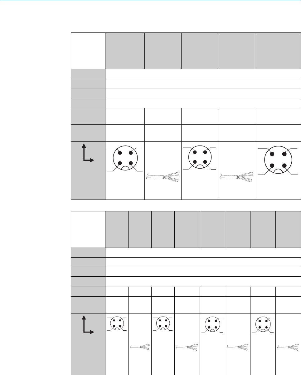
DC: 10 ... 30 V DC
Table 1: DC
WLG16 -24162xxxA00
-34162xxxA00
-1x162xxxA0
0
-24161xxxA0
0
-34161xxxA0
0
-1x161xxxA0
0
-2416xxxxA01-
A99
-3416xxxxA01-
A99
1+ (L+)
2MF
3- (M)
4QL1/C
Default: MF Q Q Q Q www.sick.com
8020349
Default:
QL1/C
Q Q Q Q www.sick.com
8020349
12
4 3
1 = brn
2 = wht
3 = blu
4 = blk
0.14 mm2
AWG26
12
4 3
1 = brn
2 = wht
3 = blu
4 = blk
0.14 mm2
AWG26
12
4 3
Table 2: DC
WLG16 -24165
xxxA00
-34165
xxxA00
-1x165
xxxA00
-24163
xxxA00
-34163
xxxA00
-1x163x
xxA00
-24166x
xxA00
-34166x
xxA00
-1x166x
xxA00
-24164x
xxA00
-34164x
xxA00
-1x164x
xxA00
1+ (L+)
2MF
3- (M)
4QL1/C
Default: MF Alarm Alarm Alarm Alarm Health Health Health Health
Default:
QL1/C
Q Q Q Q Q Q Q Q
12
4 3
1 = brn
2 = wht
3 = blu
4 = blk
0.14 m
m2
AWG26
12
4 3
1 = brn
2 = wht
3 = blu
4 = blk
0.14 m
m2
AWG26
12
4 3
1 = brn
2 = wht
3 = blu
4 = blk
0.14 m
m2
AWG26
12
4 3
1 = brn
2 = wht
3 = blu
4 = blk
0.14 m
m2
AWG26
5 ELECTRICAL INSTALLATION
68022197 | SICK
Subject to change without notice

Table 3: Push / pull
Q
Push-pull
(≤ 100 mA)
+ (L+)
Q
‒ (M)
+ (L+)
Q
‒ (M)
Q
Push-pull
(≤ 100 mA)
+ (L+)
Q
‒ (M)
+ (L+)
Q
‒ (M)
Alarm
Alarm output: The sensor (WLG16) features a pre-failure notification output (“Alarm” in
connection diagram [Table 4]), which issues a notification if the sensor is only ready for
operation to a limited extent. The LED indicator flashes in this case. Possible causes:
Sensor or reflector is contaminated, sensor is out of alignment. In the good state: LOW
(0), if excessively contaminated HIGH (1).
Health
Health output: The sensor (WLG16) features a pre-failure notification output (“Health”
in connection diagram [Table 4]), which issues a notification if the sensor is only ready
for operation to a limited extent or the cable has been interrupted. Possible causes:
Sensor or reflector is contaminated, sensor is out of alignment, cable is damaged. In
the good state: HIGH (1), if excessively contaminated or in the event of cable interrup‐
tion LOW (0). The yellow LED indicator flashes in this case.
Table 4: Alarm / Health
Alarm (≤ 100 mA) Health (≤100 mA)
+ (L+)
Alarm
‒ (M)
+ (L+)
Health
‒ (M)
+ (L+)
Alarm
‒ (M)
+ (L+)
Health
‒ (M)
ELECTRICAL INSTALLATION 5
8022197 | SICK
Subject to change without notice 7
6 Commissioning
Bluetooth® is switched on for initial commissioning. You can get SOPASair in the Google
PlayStore (Android) and in the App Store (iOS).
Operating system requirements: Android version 6.0, most current version of iOS.
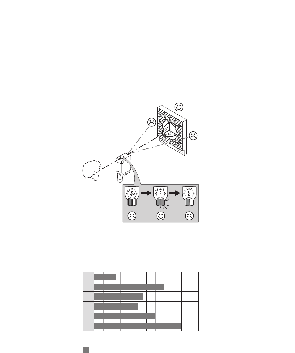
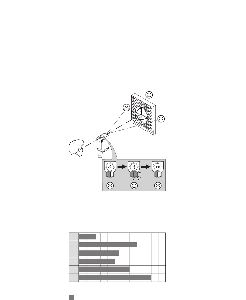
1Alignment
Align the sensor with a suitable reflector. Select the position so that the red emitted light
beam hits the center of the reflector. The sensor must have a clear view of the reflector,
with no object in the path of the beam [see figure 3]. You must ensure that the optical
openings of the sensor and reflector are completely clear.
Figure 3: Alignment
2Sensing range
Adjust the distance between the sensor and the reflector according to the corresponding
diagram [see figure 4].
Abstand in m
Schaltabstand
1
2
3
4
5
6
0 1 2 3 4 5 6
4
2,8
0
2,5
0
3,5
0
5
0
1,20
0
Figure 4: Maximum distance between the sensor and the respective reflector type
1Reflector PL10F CHEM
2Reflective tape REF-AC1000 (50 x 50 mm)
3Reflector PL10FH-1
4Reflector PL10F
5Reflector PL20F
6Reflector P250F
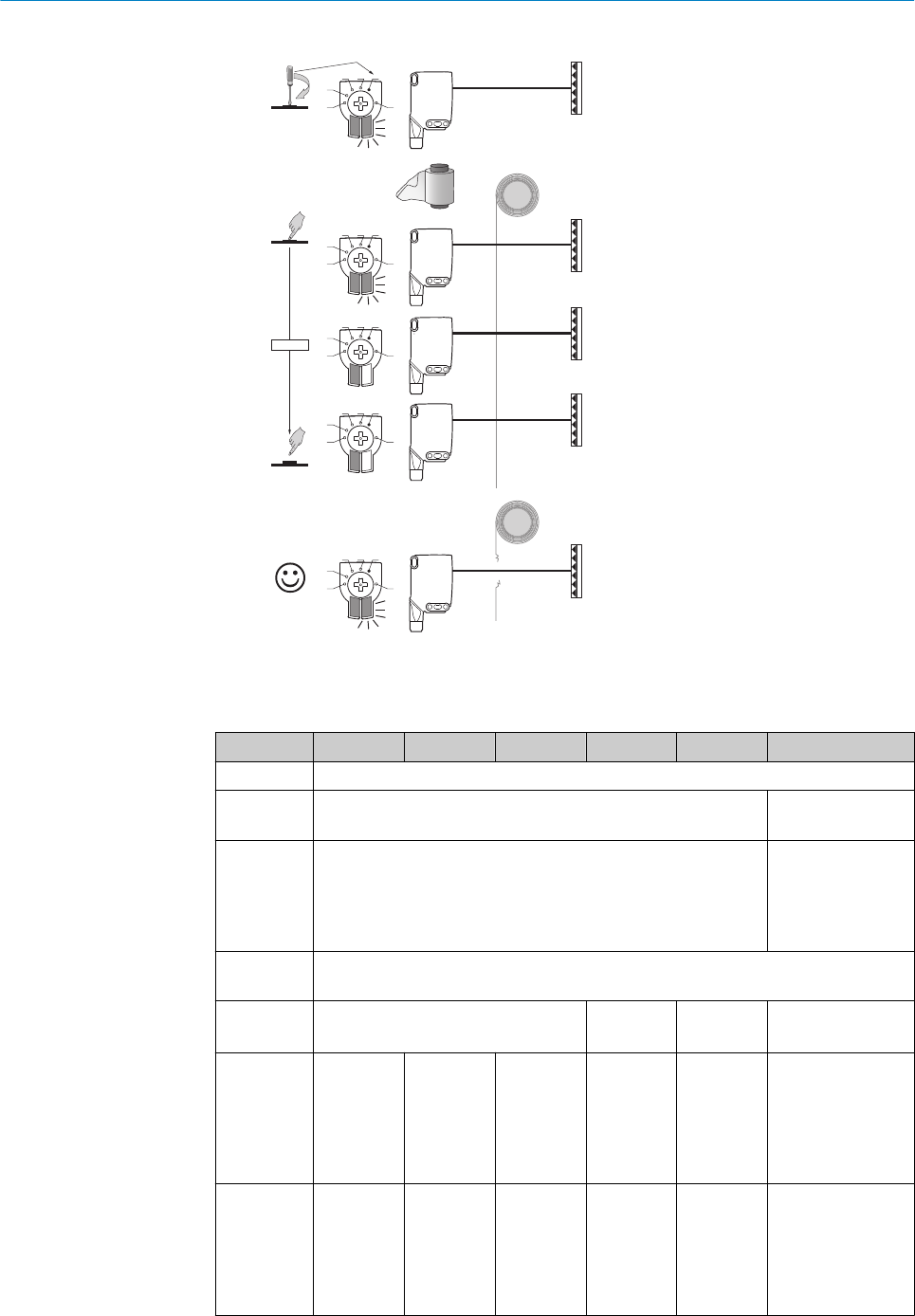
Sensing range setting
6 COMMISSIONING
88022197 | SICK
Subject to change without notice

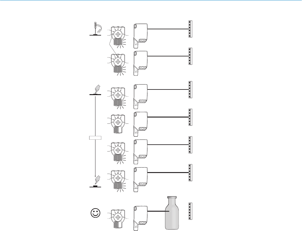
The push-turn element is used to set the object mode and switching threshold, see figures
5 and 6.
The WLG16 is equipped with AutoAdapt technology. The switching threshold is automati‐
cally adjusted in the event of contamination or after cleaning.
•Turn the press-hold element (without pressing) to set the desired object mode. The
blue indication LED lights up according to the set object mode.
•Press the press-turn element for about 1 to 3 seconds to set the switching threshold.
In the mode is changed between 1 and 4, the yellow indication LED lights up when
the reflector is in view of the sensor.
•Lead the object into the path of the beam. The yellow indication LED goes out, mean‐
ing the object is detected and the setting is correct.
•With object selection 5, the film must be in the path of the beam when the poten‐
tiometer is pressed. The yellow indication LED does not light up until the film is no
longer in the beam path. When this has been checked, the setting is correct.
•The blue indication LED of mode M lights up when a setting has been selected via IO-
Link which deviates from the predefined parameter sets of modes 1-5. This mode
cannot be selected directly on the device.
1 M
2
3 4 5
1Highly-transparent objects / Hoch-transparente Objekte / Oggetti trasparenti /
Objets ultra transparents / Objetos muy transparentes / 高透明物件
2Semi-transparent objects / Semi-transparente Objekte / Oggetti semitrasparenti /
Objets semi-transparents / Objetos semitransparentes / Semi 透明物件
3Opaque objects / Nicht-transparente Objekte / Oggetti non trasparenti / Objets
opaques / Objetos no transparentes / 不透明物件
4Bottles/trays / Flaschen/Trays / Bottiglie/vassoi / Bouteilles/trays / Botellas/
bandejas / 瓶體/托盤
5Check of foil tear / Folienriss-Kontrolle / Controllo rottura pellicola / Contrôle fis‐
sure du film / Control de rotura de lámina / 薄膜破裂檢查
MManual (specific adjustment via IO-Link) / Manuell (spezifische Einstellung via IO-
Link) / Manuale (impostazione specifica tramite IO-Link) / Manuel (réglage
spécifique via IO-Link) / Manual (ajuste específico vía IO-Link) / 手動(藉由 IO-Link
的特別設置)
COMMISSIONING 6
8022197 | SICK
Subject to change without notice 9
1 2 3 4
1 M
2
3 4 5
1 M
2
3 4 5
1 M
2
3 4 5
1 M
2
3 4 5
1 M
2
3 4 5
1 M
2
3 4 5
1 M
2
3 4 5
1...3 sec.
1
2
3
Figure 5: Object mode 1 - 4
6 COMMISSIONING
10 8022197 | SICK
Subject to change without notice
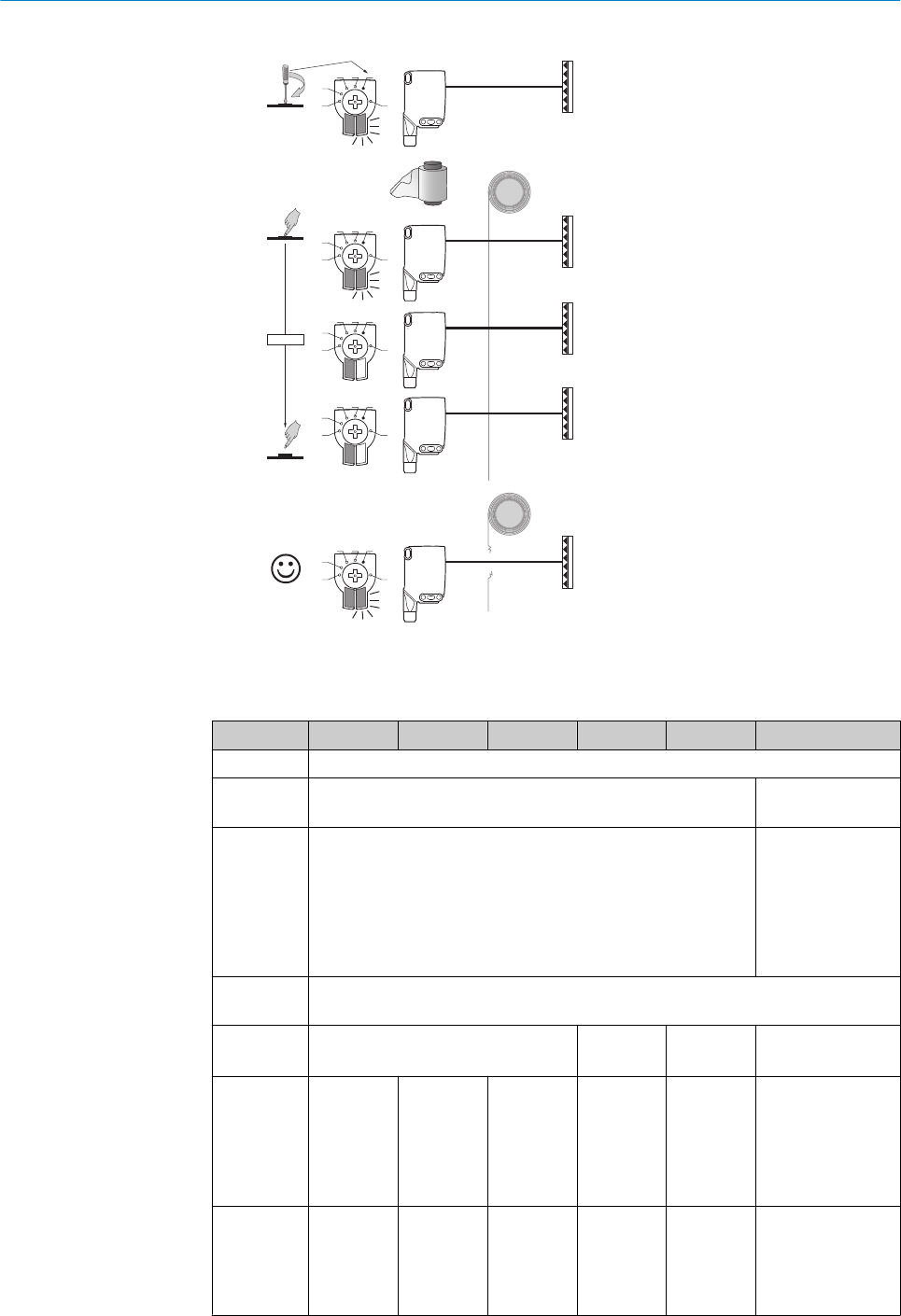
5
1 M
2
3 4 5
1 M
2
3 4 5
1 M
2
3 4 5
1 M
2
3 4 5
1 M
2
3 4 5
1...3 sec.
1
2
3
Figure 6: Object mode 5
Process data structure (Version 1.1)
A00 A70 A71 A72 A73 A75
IO-Link V1.1
Process
data
2 bytes 4 bytes
Byte 0: bits 15... 8
Byte 1: bits 7... 0
Byte 0: bits 31...
24
Byte 1: bits 13...
16
Byte 2: bits 15...
8
Byte 3: bits 7... 0
Bit 0 / Data
type
QL1 / Boolean
Bit 1 / Data
type
QL2 / Boolean Qint.1 /
Boolean
QL2 /
Boolean
Qint.1 / Boolean
Bit... /
Descrip‐
tion / Data
type
2 ...15 /
[empty]
2 ...15 /
[time mea‐
surement
value] /
UInt 14
2 … 15 /
[counter
value] /
UInt 14
2 … 15 /
[length /
speed
measure‐
ment] /
SInt14
2 / Qint.
1 /
Boolean
2 … 7 / [empty]
Bit... /
Descrip‐
tion / Data
type
3 … 15 /
[time mea‐
surement
value] /
UInt13
8 … 31 / [carrier
load] / UInt 24
COMMISSIONING 6
8022197 | SICK
Subject to change without notice 11

7 Troubleshooting
The Troubleshooting table indicates which measures are to be taken if the sensor stops
working.
LED indicator/fault pattern Cause Measures
Green LED flashes IO-Link communication None
Switching outputs do not
behave in accordance with
3
1. IO-Link communication
2. Change of the configuration
3. Short-circuit
1. None
2. Adjustment of the configura‐
tion
3. Check electrical connections
Yellow LED flashes Distance between sensor and
reflector is too large / light
beam is not completely aligned
to the reflector / reflector is not
suitable / Front screen and/or
reflector is contaminated.
Check sensing range / check
alignment / SICK reflector is
recommended / Cleaning of the
optical surfaces (sensor and
reflector).
The sensor is not displayed
in SOPASair
1. Connection to another hand-
held exists.
2.The hand-held is outside of
the transmission range of the
sensor.
3. Bluetooth LE in the sensor is
deactivated.
4. Bluetooth LE in the hand-held
is deactivated.
5. MAC address filter activated,
hand-held not authorized.
1. No connection or deactivation
of the existing connection.
2. Thorough check of installa‐
tion situation (e.g. shielding by
metal).
3. Activation of Bluetooth LE via
SiLink2 master or IO-Link
4. Activation of Bluetooth LE
5. No or change to MAC address
filter.
No connection can be
made to the sensor
1. The Android or iOS version
does not comply with require‐
ments.
2. SOPASair version does not
contain the required driver.
1. Check the operating system.
2. Uninstall SOPASair, install the
most current app version.
8 Disassembly and disposal
The sensor must be disposed of according to the applicable country-specific regula‐
tions. Efforts should be made during the disposal process to recycle the constituent
materials (particularly precious metals).
9 Maintenance
SICK sensors are maintenance-free.
We recommend doing the following regularly:
•Clean the external lens surfaces
•Check the screw connections and plug-in connections
No modifications may be made to devices.
Subject to change without notice. Specified product properties and technical data are
not written guarantees.
7 TROUBLESHOOTING
12 8022197 | SICK
Subject to change without notice

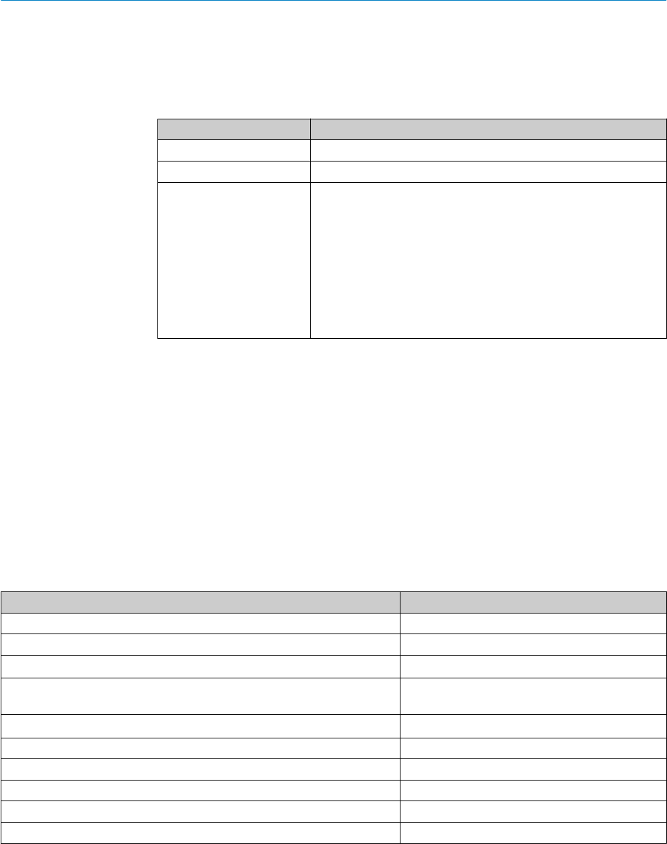
10 Approvals
10.1 Bluetooth® approvals
Country Comments
Canada IC: 21147-W16
USA FCC ID: 2AHDR-W16
Europe + EFTA EU countries
Belgium (BE), Bulgaria (BG), Denmark (DK), Germany (DE), Estonia
(EE), Finland (FI), France (FR), Greece (GR), Ireland (IE), Italy (IT),
Latvia (LV), Lithuania (LT), Luxembourg (LU), Malta (MT), Nether‐
lands (NL), Austria (AT), Poland (PL), Portugal (PT), Romania (RO),
Sweden (SE), Slovakia (SK), Slovenia (SI), Spain (ES), Czech
Republic (CZ), Hungary (HU), United Kingdom (GB), Republic of
Cyprus (CY).
EFTA countries
Iceland, Liechtenstein, Norway, Switzerland
This device complies with Part 15 of the FCC Rules and with Industry Canada licence-
exempt RSS standard(s). Operation is subject to the following two conditions: (1) this
device may not cause harmful interference, and (2) this device must accept any inter‐
ference received, including interference that may cause undesired operation.
Le présent appareil est conforme aux CNR d'Industrie Canada applicables aux
appareils radio exempts de licence. L'exploitation est autorisée aux deux conditions
suivantes: (1) l'appareil ne doit pas produire de brouillage, et (2) l'utilisateur de
l'appareil doit accepter tout brouillage radioélectrique subi, même si le brouillage est
susceptible d'en compromettre le fonctionnement.
11 Technical data
11.1 General technical data
WLG16P
Sensing range (with reflector P250F) 0 m ... 5 m1
Light spot diameter/distance Ø 80 mm (5 m)
Supply voltage VSDC 10 ... 30 V
Current consumption ≤ 30 mA2
< 50 mA3
Output current Imax. ≤ 100 mA
Max. response time ≤ 500 μs4
Switching frequency 1000 Hz5
Enclosure rating IP 66, IP 67
Protection class III
Circuit protection A, B, C, D6
APPROVALS 10
8022197 | SICK
Subject to change without notice 13

WLG16P
Ambient operating temperature –40 °C ... +60 °C
1We recommend using compound triangular reflectors or reflective tape to ensure reliable operation. Suitable reflectors and foils can be
found in the SICK accessories range. Use of reflectors with large-scale triple structures can negatively influence functionality.
216 VDC to 30 VDC, without load
310 VDC to 16 VDC, without load
4Signal transit time with resistive load in switching mode. Deviating values possible in COM2 mode.
5With a light/dark ratio of 1:1 in switching mode. Deviating values possible in IO-Link mode.
6A = UV-Anschlüsse verpolsicher
B = Ein- und Ausgänge verpolsicher
C = Störimpulsunterdrückung
D = Ausgänge überstrom- und kurzschlussfest
11.2 Bluetooth technical data®
Features Values
Bluetooth® sensing range 100 m on sight
Radio type BLE
Radio class 2
Bluetooth® module manufacturer BROADCOM
Cypress Semiconductor Corporation
198 Champion Court San Jose
CA 95134-1709
RF band 2402 - 2480 MHz
Output power 2 dBM
Declaration ID D033906
Qualified design ID 89630
Specification name 4.1
Member company SICK AG
11 TECHNICAL DATA
14 8022197 | SICK
Subject to change without notice
Beschriebenes Produkt
WLG16 - Bluetooth®
Hersteller
SICK AG
Erwin-Sick-Str. 1
79183 Waldkirch
Deutschland
Rechtliche Hinweise
Dieses Werk ist urheberrechtlich geschützt. Die dadurch begründeten Rechte bleiben
bei der Firma SICK AG. Die Vervielfältigung des Werks oder von Teilen dieses Werks ist
nur in den Grenzen der gesetzlichen Bestimmungen des Urheberrechtsgesetzes zuläs‐
sig. Jede Änderung, Kürzung oder Übersetzung des Werks ohne ausdrückliche schriftli‐
che Zustimmung der Firma SICK AG ist untersagt.
Die in diesem Dokument genannten Marken sind Eigentum ihrer jeweiligen Inhaber.
© SICK AG. Alle Rechte vorbehalten.
Originaldokument
Dieses Dokument ist ein Originaldokument der SICK AG.
16 8022197 | SICK
Subject to change without notice

Inhalt
12 Zu Ihrer Sicherheit............................................................................. 18
12.1 Allgemeine Sicherheitshinweise.............................................................. 18
12.2 Hinweise zur UL Zulassung...................................................................... 18
13 Bestimmungsgemäße Verwendung............................................... 18
14 Bedien- und Anzeigeelemente........................................................ 18
15 Montage.............................................................................................. 19
16 Elektrische Installation..................................................................... 19
17 Inbetriebnahme................................................................................. 22
18 Störungsbehebung............................................................................ 26
19 Demontage und Entsorgung............................................................ 26
20 Wartung.............................................................................................. 26
21 Zulassungen....................................................................................... 27
21.1 Bluetooth® Zulassungen......................................................................... 27
22 Technische Daten.............................................................................. 27
22.1 Allgemeine Technische Daten.................................................................. 27
22.2 Technische Daten Bluetooth®................................................................. 28
INHALT
8022197 | SICK
Subject to change without notice 17

12 Zu Ihrer Sicherheit
12.1 Allgemeine Sicherheitshinweise
■Vor der Inbetriebnahme die Betriebsanleitung lesen.
■
Anschluss, Montage und Einstellung nur durch Fachpersonal.
■Kein Sicherheitsbauteil gemäß EU-Maschinenrichtlinie.
■Gerät bei Inbetriebnahme vor Feuchte und Verunreinigung schützen.
■Diese Betriebsanleitung enthält Informationen, die während des Lebenszyklus des
Sensors notwendig sind.
12.2 Hinweise zur UL Zulassung
The device must be supplied by a limited voltage / limited current circuit or is intended
to be connected to a Class 2 source of supply. In case of a limited voltage / limited cur‐
rent circuit the device shall be supplied from an isolating transformer having a secon‐
dary overcurrent protective device that complies with UL 248 to be installed in the field
rated either:
a) max 5 amps for voltages 0~20 V (0~28.3 V peak), or
b) 100/Vp for voltages of 20~30 V (28.3~42.4 V peak).
UL Environmental Rating: Enclosure type 1
13 Bestimmungsgemäße Verwendung
Die WLG16 ist eine optoelektronische Reflexions-Lichtschranke (im Folgenden Sensor
genannt) und wird zum optischen, berührungslosen Erfassen von Sachen, Tieren und
Personen eingesetzt. Zur Funktion wird ein Reflektor benötigt. Bei jeder anderen Ver‐
wendung und bei Veränderungen am Produkt verfällt jeglicher Gewährleistungsan‐
spruch gegenüber der SICK AG.
Reflexions-Lichtschranke mit Zusatzoption zur Erkennung transparenter Objekte (WLG-
xx).
14 Bedien- und Anzeigeelemente
12 ZU IHRER SICHERHEIT
18 8022197 | SICK
Subject to change without notice

20
Ø 12,9
Ø 4,1
39,9
55,4
45,5 5
42
29,9
6
3
6,5
15
27,8
7,7
7,8
7,2
35,5
4,1
8,3
55,7
3
2
34,5
1
4
65
Abbildung 7: Maßzeichnung 1, Leitung
1Mitte Optikachse
2Befestigungsbohrung, Ø 4,1 mm
3Anschluss
4Anzeige-LED grün: Betriebsspan‐
nung aktiv
5Anzeige-LED gelb: Status Lichtemp‐
fang
6BluePilot blau: Ausrichthilfe
20
M12
18
Ø 4,1
39,9
55,4
55,7
45,5 5
7
42
29,9
52,9
6
17,5
3
6,5
15
28
7,5
35,5
4,1
3
2
34,5
1
4
65
Abbildung 8: Maßzeichnung 2, Stecker
15 Montage
Sensor und Reflektor an geeignete Befestigungswinkel montieren (siehe SICK-Zubehör-
Programm). Sensor und Reflektor zueinander ausrichten.
Maximal zulässiges Anzugsdrehmoment des Sensors von < 1,3 Nm beachten.
16 Elektrische Installation
Anschluss der Sensoren muss spannungsfrei (UV = 0 V) erfolgen. Je nach Anschlussart
sind die folgenden Informationen zu beachten:
– Steckeranschluss: Pinbelegung beachten
– Leitung: Adernfarbe
Erst nach Anschluss aller elektrischen Verbindungen die Spannungsversorgung (UV > 0
V) anlegen bzw. einschalten.
Erläuterungen zum Anschlussschema (Tabellen 1 und 2).
Alarm = Alarmausgang (siehe Tabelle 4)
Health = Alarmausgang (siehe Tabelle 4)
MF (Pin-2-Konfiguration) = externer Eingang, Teach-in, Schaltsignal
QL1 / C = Schaltausgang, IO-Link Kommunikation
BEDIEN- UND ANZEIGEELEMENTE 14
8022197 | SICK
Subject to change without notice 19

DC: 10 ... 30 V DC
Tabelle 5: DC
WLG16 -24162xxxA00
-34162xxxA00
-1x162xxxA0
0
-24161xxxA0
0
-34161xxxA0
0
-1x161xxxA0
0
-2416xxxxA01-
A99
-3416xxxxA01-
A99
1+ (L+)
2MF
3- (M)
4QL1/C
Default: MF Q Q Q Q www.sick.com
8020349
Default:
QL1/C
Q Q Q Q www.sick.com
8020349
12
4 3
1 = brn
2 = wht
3 = blu
4 = blk
0.14 mm2
AWG26
12
4 3
1 = brn
2 = wht
3 = blu
4 = blk
0.14 mm2
AWG26
12
4 3
Tabelle 6: DC
WLG16 -24165
xxxA00
-34165
xxxA00
-1x165
xxxA00
-24163
xxxA00
-34163
xxxA00
-1x163x
xxA00
-24166x
xxA00
-34166x
xxA00
-1x166x
xxA00
-24164x
xxA00
-34164x
xxA00
-1x164x
xxA00
1+ (L+)
2MF
3- (M)
4QL1/C
Default: MF Alarm Alarm Alarm Alarm Health Health Health Health
Default:
QL1/C
Q Q Q Q Q Q Q Q
12
4 3
1 = brn
2 = wht
3 = blu
4 = blk
0.14
mm2
AWG26
12
4 3
1 = brn
2 = wht
3 = blu
4 = blk
0.14
mm2
AWG26
12
4 3
1 = brn
2 = wht
3 = blu
4 = blk
0.14
mm2
AWG26
12
4 3
1 = brn
2 = wht
3 = blu
4 = blk
0.14
mm2
AWG26
16 ELEKTRISCHE INSTALLATION
20 8022197 | SICK
Subject to change without notice
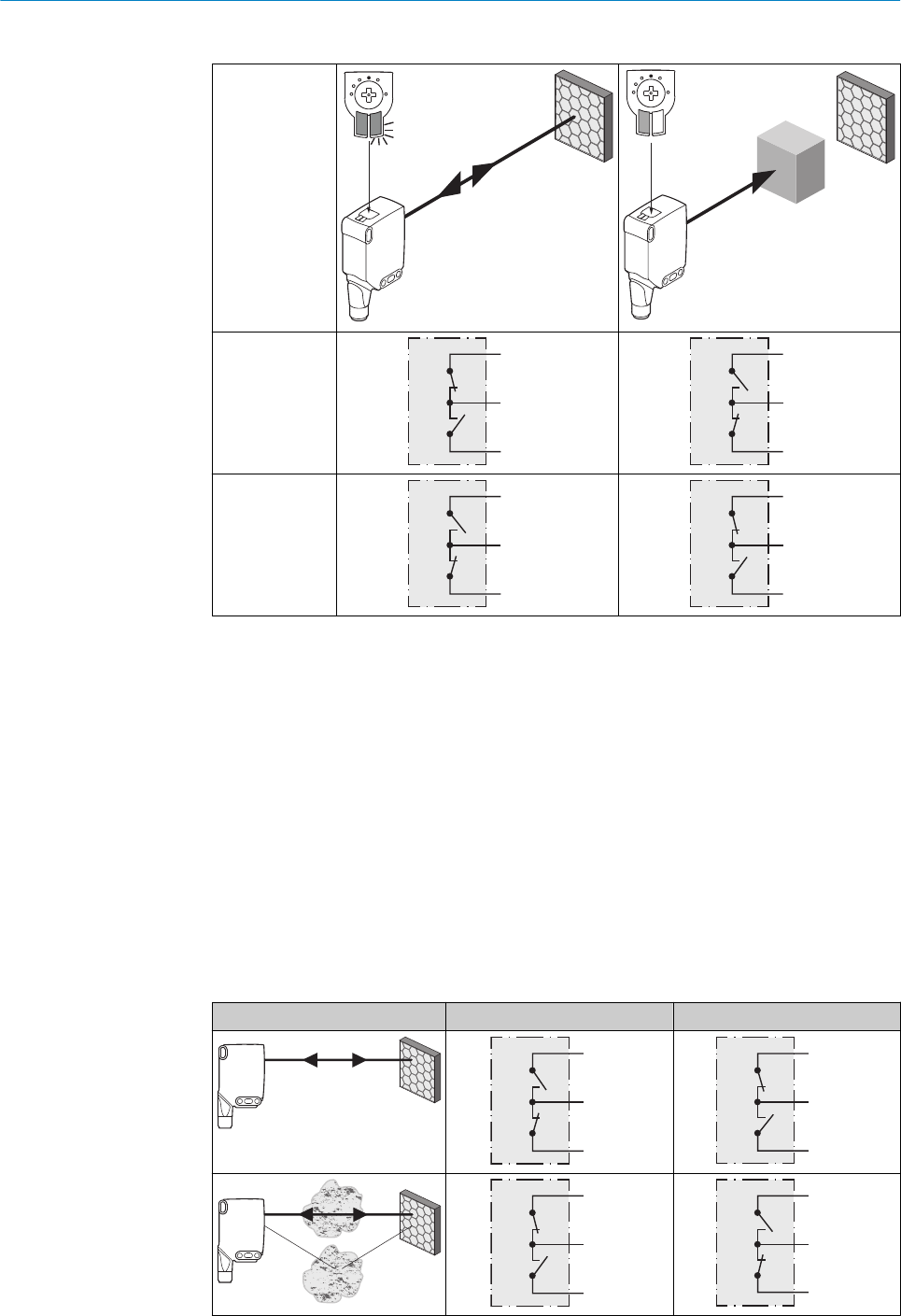
Tabelle 7: Push / Pull
Q
push-pull
(≤ 100 mA)
+ (L+)
Q
‒ (M)
+ (L+)
Q
‒ (M)
Q
push-pull
(≤ 100 mA)
+ (L+)
Q
‒ (M)
+ (L+)
Q
‒ (M)
Alarm
Alarmausgang: Der Sensor (WLG16) verfügt über einen Vorausfallmeldeausgang
("Alarm" im Anschlussschema [Tabelle 4]), der meldet, wenn der Sensor nur noch ein‐
geschränkt betriebsbereit ist. Dabei blinkt die Anzeige-LED. Mögliche Ursachen: Ver‐
schmutzung von Sensor oder Reflektor, Sensor ist dejustiert. Im Gutzustand: LOW (0),
bei zu starker Verschmutzung HIGH (1).
Health
Health-Ausgang: Der Sensor (WLG16) verfügt über einen Vorausfallmeldeausgang
("Health" im Anschlussschema [Tabelle 4]), der meldet, wenn der Sensor nur noch ein‐
geschränkt betriebsbereit ist oder die Leitung unterbrochen ist. Mögliche Ursachen:
Verschmutzung von Sensor oder Reflektor, Sensor ist dejustiert, Leitung ist beschädigt.
Im Gutzustand: HIGH (1), bei zu starker Verschmutzung oder Leitungsunterbrechung
LOW (0). Dabei blinkt die gelbe Anzeige-LED.
Tabelle 8: Alarm / Health
Alarm (≤ 100 mA) Health (≤100 mA)
+ (L+)
Alarm
‒ (M)
+ (L+)
Health
‒ (M)
+ (L+)
Alarm
‒ (M)
+ (L+)
Health
‒ (M)
ELEKTRISCHE INSTALLATION 16
8022197 | SICK
Subject to change without notice 21
17 Inbetriebnahme
Bluetooth® ist bei der Ersteinbetriebnahme eingeschaltet. SOPASair erhalten Sie im
Google PlayStore (Android) und im App Store (iOS).
Anforderungen an das Betriebssystem: Android-Version 6.0, iOS aktuellste Version.
1Ausrichtung
Sensor auf geeigneten Reflektor ausrichten. Positionierung so wählen, dass der rote Sen‐
delichtstrahl in der Mitte des Reflektors auftrifft. Der Sensor muss freie Sicht auf den
Reflektor haben, es darf sich kein Objekt im Strahlengang befinden [siehe Abbildung 9]. Es
ist darauf zu achten, dass die optischen Öffnungen von Sensor und Reflektor vollständig
frei sind.
Abbildung 9: Ausrichtung
2Schaltabstand
Distanz zwischen Sensor und Reflektor mit dem zugehörigen Diagramm [siehe Abbildung
4] abgleichen.
Abstand in m
Schaltabstand
1
2
3
4
5
6
0 1 2 3 4 5 6
4
2,8
0
2,5
0
3,5
0
5
0
1,20
0
Abbildung 10: maximaler Abstand zwischen Sensor und dem jeweiligen Reflektortyp
1Reflektor PL10F CHEM
2Reflexionsfolie REF-AC1000 (50 x 50 mm)
3Reflektor PL10FH-1
4Reflektor PL10F
5Reflektor PL20F
6Reflektor P250F
17 INBETRIEBNAHME
22 8022197 | SICK
Subject to change without notice

Einstellung Schaltabstand
Mit dem Drück-Dreh-Element werden Objektmodus und Schaltschwelle eingestellt, siehe
Abbildungen 5 und 6.
Die WLG16 ist mit der AutoAdapt-Technologie ausgestattet. Im Falle einer Verschmutzung
oder nach einer Reinigung wird die Schaltschwelle automatisch angepasst.
•Drehen Sie das Drück-Dreh-Element (ohne zu drücken), um den gewünschten Objekt‐
modus einstellen. Eine blaue Anzeige-LED leuchtet entsprechend dem eingestellten
Objektmodus .
•Drücken Sie das Drück-Dreh-Element für ca. 1…3 sec., um die Schaltschwelle einzu‐
stellen.
Im Falle der Moduswahl 1 bis 4 leuchtet die gelbe Anzeige-LED bei Sicht des Sensors
auf den Reflektor.
•Führen Sie das Objekt in den Strahlengang, die gelbe Anzeige-LED erlischt, d.h. das
Objekt wird erkannt und die Einstellung ist korrekt.
•Bei der Objektauswahl 5 muss sich die Folie im Strahlengang befinden, während
dem Drücken des Potentiometers. Die gelbe Anzeige-LED leuchtet erst, wenn sich die
Folie nicht mehr im Strahlengang befindet. Wenn dies überprüft wurde, dann ist die
Einstellung korrekt.
•Die blaue Anzeige-LED des Modus M leuchtet, wenn via IO-Link eine Einstellung
gewählt wurde, welche von den vordefinierten Parameter-Sets der Modi 1-5 abweicht.
Dieser Modus kann nicht direkt am Gerät angewählt werden.
1 M
2
3 4 5
1Highly-transparent objects / Hoch-transparente Objekte / Oggetti trasparenti /
Objets ultra transparents / Objetos muy transparentes / 高透明物件
2Semi-transparent objects / Semi-transparente Objekte / Oggetti semitrasparenti /
Objets semi-transparents / Objetos semitransparentes / Semi 透明物件
3Opaque objects / Nicht-transparente Objekte / Oggetti non trasparenti / Objets
opaques / Objetos no transparentes / 不透明物件
4Bottles/trays / Flaschen/Trays / Bottiglie/vassoi / Bouteilles/trays / Botellas/
bandejas / 瓶體/托盤
5Check of foil tear / Folienriss-Kontrolle / Controllo rottura pellicola / Contrôle fis‐
sure du film / Control de rotura de lámina / 薄膜破裂檢查
MManual (specific adjustment via IO-Link) / Manuell (spezifische Einstellung via IO-
Link) / Manuale (impostazione specifica tramite IO-Link) / Manuel (réglage spécifi‐
que via IO-Link) / Manual (ajuste específico vía IO-Link) / 手動(藉由 IO-Link 的特
別設置)
INBETRIEBNAHME 17
8022197 | SICK
Subject to change without notice 23

1 2 3 4
1 M
2
3 4 5
1 M
2
3 4 5
1 M
2
3 4 5
1 M
2
3 4 5
1 M
2
3 4 5
1 M
2
3 4 5
1 M
2
3 4 5
1...3 sec.
1
2
3
Abbildung 11: Objektmodus 1 - 4
17 INBETRIEBNAHME
24 8022197 | SICK
Subject to change without notice
5
1 M
2
3 4 5
1 M
2
3 4 5
1 M
2
3 4 5
1 M
2
3 4 5
1 M
2
3 4 5
1...3 sec.
1
2
3
Abbildung 12: Objektmodus 5
Process data structure (Version 1.1)
A00 A70 A71 A72 A73 A75
IO-Link V1.1
Process
data
2 Byte 4 Byte
Byte 0 : Bit 15... 8
Byte 1: Bit 7... 0
Byte 0 : Bit 31...
24
Byte 1: Bit 13... 16
Byte 2: Bit 15... 8
Byte 3: Bit 7... 0
Bit 0/ Data
type
QL1 / Boolean
Bit 1/ Data
type
QL2 / Boolean Qint.1 /
Boolean
QL2 / Boo‐
lean
Qint.1 / Boolean
Bit... /
Descrip‐
tion / Data
type
2...15 /
[empty]
2...15 /
[Time
measure‐
ment
value] /
UInt 14
2 … 15 /
[Counter
value] /
UInt 14
2 … 15 /
[Length /
speed
measure‐
ment] /
SInt14
2 / Qint.
1 / Boo‐
lean
2…7 / [empty]
Bit... /
Descrip‐
tion / Data
type
3 … 15 /
[Time
measure‐
ment
value] /
UInt13
8 … 31 / [Carrier
load] / UInt 24
INBETRIEBNAHME 17
8022197 | SICK
Subject to change without notice 25

18 Störungsbehebung
Tabelle Störungsbehebung zeigt, welche Maßnahmen durchzuführen sind, wenn die
Funktion des Sensors nicht mehr gegeben ist.
Anzeige-LED / Fehlerbild Ursache Maßnahme
grüne LED blinkt IO-Link Kommunikation keine
Schaltausgänge verhalten
sich nicht gemäß 3
1. IO-Link Kommunikation
2. Änderung der Konfiguration
3. Kurzschluss
1. keine
2. Anpassung der Konfiguration
3. Elektrische Anschlüsse prü‐
fen
gelbe LED blinkt Abstand zwischen Sensor und
Reflektor ist zu groß / Licht‐
strahl ist nicht vollständig auf
Reflektor ausgerichtet / Reflek‐
tor ist nicht geeignet / Fronst‐
scheibe und/oder Reflektor ist
verschmutzt.
Schaltabstand prüfen / Ausrich‐
tung prüfen / Reflektor von SICK
wird empfohlen. / Reinigung der
optischen Flächen (Sensor und
Reflektor).
In SOPASair wird der Sen‐
sor nicht angezeigt
1. Verbindung zu einem ande‐
ren Handheld besteht.
2.Das Handheld befindet sich
außerhalb des Sendebereichs
des Sensors.
3. Bluetooth LE im Sensor ist
deaktiviert.
4. Bluetooth LE im Handheld ist
deaktiviert.
5. MAC-Adressfilter aktiviert,
Handheld nicht autorisiert.
1. keine bzw. Deaktivierung der
bestehenden Verbindung.
2. Prüfung der Einbausituation
(z.B. Abschirmung durch Metall).
3. Aktivierung von Bluetooth LE
per SiLink2 Master oder IO-Link
4. Aktivierung von Bluetooth LE
5. keine bzw. Änderung des
MAC-Adress-Filters.
Es kann keine Verbindung
zum Sensor aufgebaut wer‐
den
1. Die Android bzw. iOS-Version
entspricht nicht den Anforderun‐
gen.
2. SOPASair Version enthält
nicht den erforderlichen Treiber.
1. Prüfen Sie das Betriebssys‐
tem.
2. Deinstallieren Sie SOPASair,
Installieren Sie die aktuellste
App-Version.
19 Demontage und Entsorgung
Die Entsorgung des Sensors hat gemäß den länderspezifisch anwendbaren Vorschrif‐
ten zu erfolgen. Für die enthaltenen Wertstoffe (insbesondere Edelmetalle) ist im Rah‐
men der Entsorgung eine Verwertung anzustreben.
20 Wartung
SICK-Sensoren sind wartungsfrei.
Wir empfehlen, in regelmäßigen Abständen
•die optischen Grenzflächen zu reinigen
•Verschraubungen und Steckverbindungen zu überprüfen
Veränderungen an Geräten dürfen nicht vorgenommen werden.
Irrtümer und Änderungen vorbehalten. Angegebene Produkteigenschaften und techni‐
sche Daten stellen keine Garantieerklärung dar.
18 STÖRUNGSBEHEBUNG
26 8022197 | SICK
Subject to change without notice
21 Zulassungen
21.1 Bluetooth® Zulassungen
Land Kommentare
Canada IC: 21147-W16
USA FCC ID: 2AHDR-W16
Europa + EFTA EU Länder
Belgium (BE), Bulgaria (BG), Denm ark (DK), Germany (DE), Esto‐
nia (EE), Finland (FI), France (FR), Greece (GR), Ireland (IE), Italy
(IT), Latvia (LV), Lithuania (LT), Luxembourg (LU), Malta (MT),
Netherlands (NL), Austria (AT), Poland (PL), Portugal (PT), Romania
(RO), Sweden (SE), Slovakia (SK), Slovenia (SI), Spain (ES), Czech
Republic (CZ), Hungary (HU), Unit ed Kingdom (GB), Republic of
Cyprus (CY).
EFTA Länder
Iceland, Liechtenstein, Norway, Switzerland
This device complies with Part 15 of the FCC Rules and with Industry Canada licence-
exempt RSS standard(s). Operation is subject to the following two conditions: (1) this
device may not cause harmful interference, and (2) this device must accept any interfe‐
rence received, including interference that may cause undesired operation.
Le présent appareil est conforme aux CNR d'Industrie Canada applicables aux appa‐
reils radio exempts de licence. L'exploitation est autorisée aux deux conditions suivan‐
tes: (1) l'appareil ne doit pas produire de brouillage, et (2) l'utilisateur de l'appareil doit
accepter tout brouillage radioélectrique subi, même si le brouillage est susceptible d'en
compromettre le fonctionnement.
22 Technische Daten
22.1 Allgemeine Technische Daten
WLG16P
Schaltabstand (mit Reflektor P250F) 0 m ... 5 m1
Lichtfleckdurchmesser/Entfernung Ø 80 mm (5 m)
Versorgungsspannung UVDC 10 ... 30 V
Stromaufnahme ≤ 30 mA2
< 50 mA3
Ausgangsstrom Imax. ≤ 100 mA
Ansprechzeit max. ≤ 500 μs4
Schaltfrequenz 1000Hz5
Schutzart IP 66, IP 67
Schutzklasse III
Schutzschaltungen A, B, C, D6
ZULASSUNGEN 21
8022197 | SICK
Subject to change without notice 27

WLG16P
Betriebsumgebungstemperatur –40 °C ... +60 °C
1Für einen zuverlässigen Betrieb empfehlen wir die Verwendung von Feintripel-Reflektoren oder Reflexionsfolie. Geeignete Reflektoren und
Folien finden Sie im Zubehör-Programm von Sick. Die Verwendung von Reflektoren mit großer Tripelstruktur kann die Funktionsfähigkeit
beeinträchtigen.
216VDC...30VDC, ohne Last
310VDC...16VDC, ohne Last
4Signallaufzeit bei ohmscher Last im Schaltmodus. Abweichende Werte im COM2-Modus möglich.
5Bei Hell-Dunkel-Verhältnis 1:1 im Schaltmodus. Abweichende Werte im IO-Link-Modus möglich.
6A = UV-Anschlüsse verpolsicher
B = Ein- und Ausgänge verpolsicher
C = Störimpulsunterdrückung
D = Ausgänge überstrom- und kurzschlussfest
22.2 Technische Daten Bluetooth®
Merkmale Werte
Bluetooth® Reichweite 100 m auf Sicht
Funkart BLE
Funkklasse 2
Hersteller Bluetooth® Modul BROADCOM
Cypress Semiconductor Corporation
198 Champion Court San Jose
CA 95134-1709
RF Band 2402 - 2480 MHz
Ausgangs-Leistung 2 dBM
Declaration ID D033906
Qualified Design ID 89630
Specification Name 4.1
Mitglieds Unternehmen SICK AG
22 TECHNISCHE DATEN
28 8022197 | SICK
Subject to change without notice

Australia
Phone +61 3 9457 0600
1800 334 802 – tollfree
E-Mail sales@sick.com.au
Austria
Phone +43 22 36 62 28 8-0
E-Mail office@sick.at
Belgium/Luxembourg
Phone +32 2 466 55 66
E-Mail info@sick.be
Brazil
Phone +55 11 3215-4900
E-Mail marketing@sick.com.br
Canada
Phone +1 905 771 14 44
E-Mail information@sick.com
Czech Republic
Phone +420 2 57 91 18 50
E-Mail sick@sick.cz
Chile
Phone +56 2 2274 7430
E-Mail info@schadler.com
China
Phone +86 20 2882 3600
E-Mail info.china@sick.net.cn
Denmark
Phone +45 45 82 64 00
E-Mail sick@sick.dk
Finland
Phone +358-9-2515 800
E-Mail sick@sick.fi
France
Phone +33 1 64 62 35 00
E-Mail info@sick.fr
Germany
Phone +49 211 5301-301
E-Mail info@sick.de
Hong Kong
Phone +852 2153 6300
E-Mail ghk@sick.com.hk
Hungary
Phone +36 1 371 2680
E-Mail office@sick.hu
India
Phone +91 22 4033 8333
E-Mail info@sick-india.com
Israel
Phone +972 4 6881000
E-Mail info@sick-sensors.com
Italy
Phone +39 02 274341
E-Mail info@sick.it
Japan
Phone +81 3 5309 2112
E-Mail support@sick.jp
Malaysia
Phone +6 03 8080 7425
E-Mail enquiry.my@sick.com
Mexico
Phone +52 472 748 9451
E-Mail mario.garcia@sick.com
Netherlands
Phone +31 30 2044 000
E-Mail info@sick.nl
New Zealand
Phone +64 9 415 0459
0800 222 278 – tollfree
E-Mail sales@sick.co.nz
Norway
Phone +47 67 81 50 00
E-Mail sick@sick.no
Poland
Phone +48 22 539 41 00
E-Mail info@sick.pl
Romania
Phone +40 356 171 120
E-Mail office@sick.ro
Russia
Phone +7 495 775 05 30
E-Mail info@sick.ru
Singapore
Phone +65 6744 3732
E-Mail sales.gsg@sick.com
Slovakia
Phone +421 482 901201
E-Mail mail@sick-sk.sk
Slovenia
Phone +386 591 788 49
E-Mail office@sick.si
South Africa
Phone +27 11 472 3733
E-Mail info@sickautomation.co.za
South Korea
Phone +82 2 786 6321
E-Mail info@sickkorea.net
Spain
Phone +34 93 480 31 00
E-Mail info@sick.es
Sweden
Phone +46 10 110 10 00
E-Mail info@sick.se
Switzerland
Phone +41 41 619 29 39
E-Mail contact@sick.ch
Taiwan
Phone +886 2 2375-6288
E-Mail sales@sick.com.tw
Thailand
Phone +66 2645 0009
E-Mail Ronnie.Lim@sick.com
Turkey
Phone +90 216 528 50 00
E-Mail info@sick.com.tr
United Arab Emirates
Phone +971 4 88 65 878
E-Mail info@sick.ae
United Kingdom
Phone +44 1727 831121
E-Mail info@sick.co.uk
USA
Phone +1 800 325 7425
E-Mail info@sick.com
Vietnam
Phone +84 945452999
E-Mail Ngo.Duy.Linh@sick.com
Further locations at www.sick.com
SICK
8022197 | SICK
Subject to change without notice 29