Siemens Canada Siemens Milltronics Process Instruments IQ300 User Manual Manual Title
Siemens Canada Ltd. - Siemens Milltronics Process Instruments Manual Title
UserManual.wiki
>
Siemens Canada Siemens Milltronics Process Instruments
>
IQ300 User Manual
users manual
Navigation menu
Upload a User Manual
Namespaces
Wiki Guide
HTML
PDF
Info
Views
User Manual
Discussion / Help
Navigation

![PL-611 IQ Radar 300 Page 9General InformationGeneral InformationGeneral InformationGeneral InformationIQ Radar 300 Communication SystemsThe IQ Radar 300 is a level monitoring instrument using advanced pulse radartechniques that communicates component and system status to a Supervisory Controland Data Acquisition (SCADA) system.. [graphic will be revised]The standard IQ 300 supports Modbus communications on board and Hear and ProfibusPA via add-on cards.DolphinDolphin is a proprietary Milltronics protocol designed to be used with Dolphin Plus. Formore information on Dolphin Plus, or to obtain a copy of the software, contact yourMilltronics representative.ModbusModbus is an industry standard protocol used by SCADA and HMI systems, and uses theIQ Radar 300’s RS-232 ports to communicate. For a description of the Modbus protocol,contact your local Schneider representative.Optional SmartLinx®CardsThe standard IQ Radar 300 unit may also be enhanced with Milltronics’ SmartLinx®communication modules that interface with popular industrial communication systems.This manual only describes the built-in communications. For more information onSmartLinx, please consult the appropriate SmartLinx manual.radio modemIQ 300 unit](https://usermanual.wiki/Siemens-Canada-Siemens-Milltronics-Process-Instruments/IQ300/User-Guide-132603-Page-7.png)


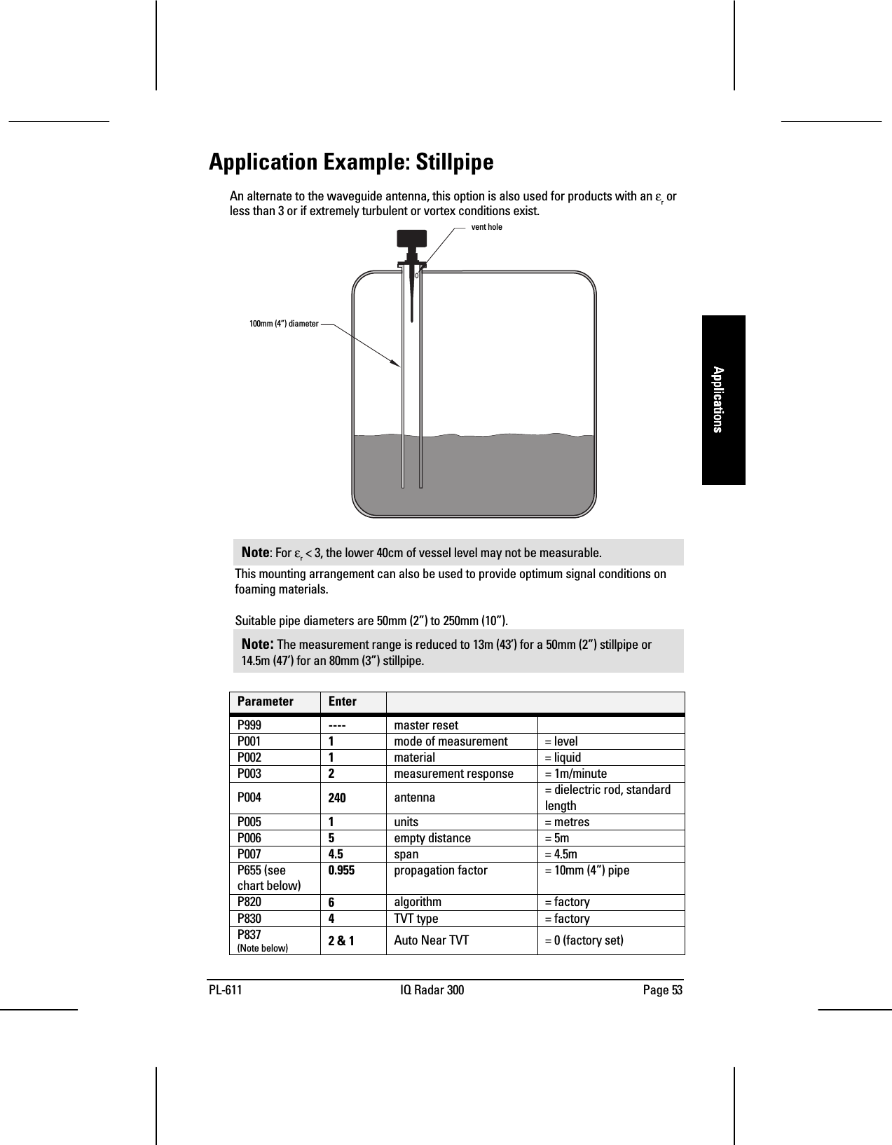
![Page 30 IQ Radar 300 PL-611InstallationInstallationInstallationInstallationMounting: Stillpipe or SidepipeAn alternate to the waveguide antenna, this option is also used for products with an εrless than 3 or for extremely turbulent or vortex conditions. This mounting arrangementcan also be used to provide optimum signal conditions on foaming materials.Suitable pipe diameters are 2” (50mm) to 10” (250mm). A rod antenna or a horn antennamay be used.Note: : : : The measurement range is reduced to 13m (43’) for a 50mm (2”) stillpipe or14.5m (47’) for an 80mm (3”) stillpipe.SmoothnessOne continuous length of metallic pipe is preferred (no joints). If long length dictates theneed for joints, then you must machine the joints to close tolerances (± 0.25mm [±0.010”]) and weld a connecting sleeve on the outside.See P655 on page 67.Ensure there is a vent at the upper end of the surge pipe to equalize pressure and keepthe liquid level in the pipe constant with level in the vessel.vent holeSuitable pipe diameters are 2” (50mm) to10” (250mm).You can use either a Rod or Hornantenna.](https://usermanual.wiki/Siemens-Canada-Siemens-Milltronics-Process-Instruments/IQ300/User-Guide-132603-Page-28.png)
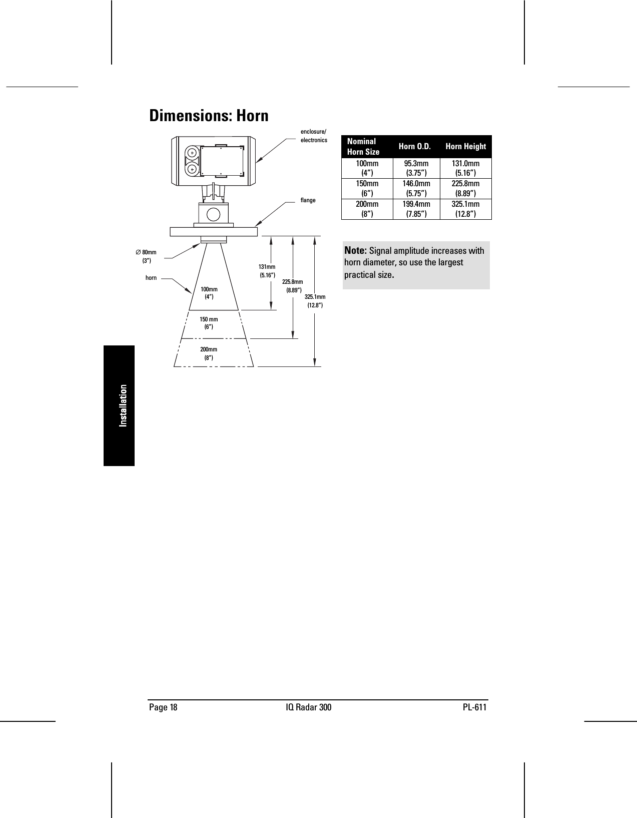
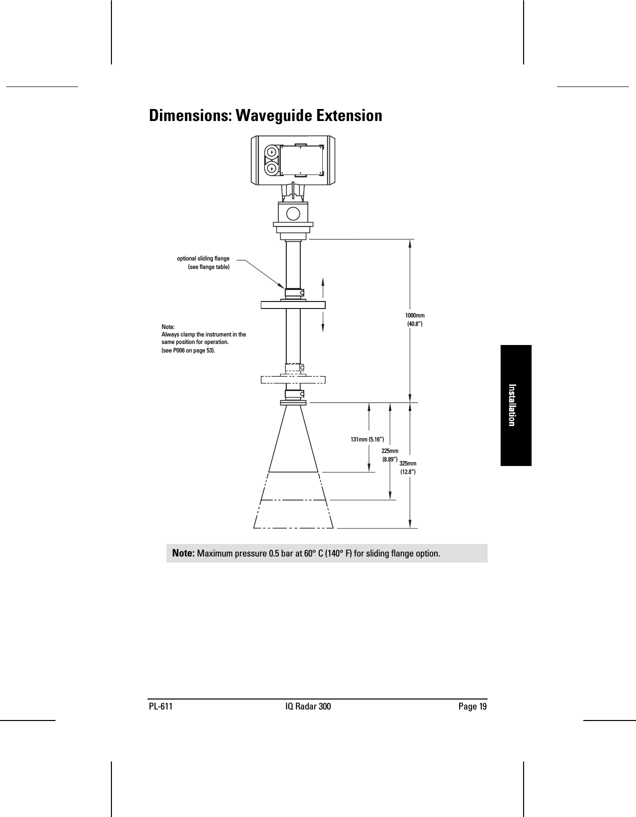
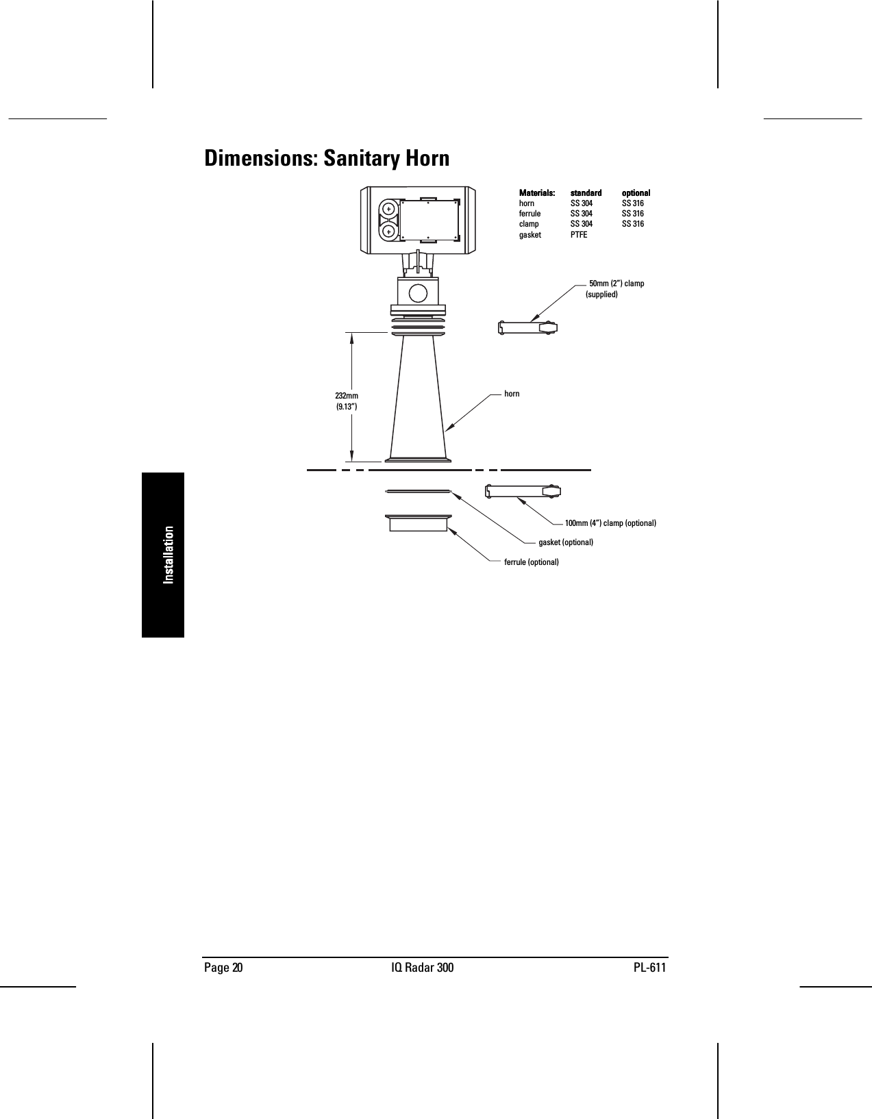
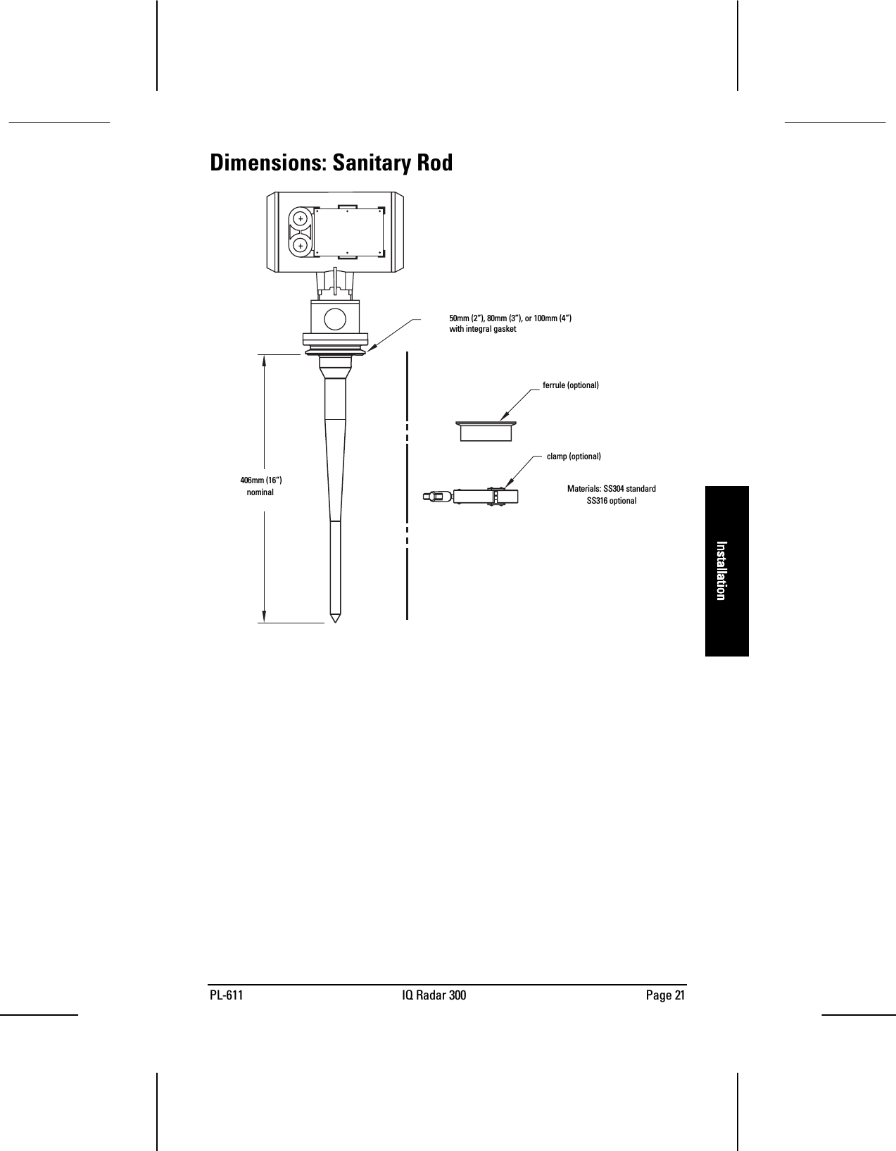
![PL-611 IQ Radar 300 Page 31InstallationInstallationInstallationInstallationMounting: Horn with Waveguide ExtensionsIn applications where the standpipe is too longand the diameter is too small (such as astandpipe that is 100mm (4”) in diameter and460mm (18”) in length), the rod antenna is notsuitable due to standpipe interference. In thiscase, use the waveguide/horn combination.Waveguide extensions are available in customlengths.Note:Note:Note:Note: The IQ 300 maximum range of ??m is reduced by [0.64 x waveguide length].Blanking and offset parameters are set by Milltronics. See the device tag for values.Mounting: Sanitary MountingThere are two common sanitary mounting options; the 2”, 3”, and 4” tri-clamp with rodantenna and the sanitary 4” horn antenna.Wetted Parts:Wetted Parts:Wetted Parts:Wetted Parts:PTFE or UHMW-PE only.If the horn diameter is too large for the standpipeopening, you need to insert it from inside the vessel.The horn must be connected to the IQ 300 processflange.](https://usermanual.wiki/Siemens-Canada-Siemens-Milltronics-Process-Instruments/IQ300/User-Guide-132603-Page-29.png)
![Page 32 IQ Radar 300 PL-611InstallationInstallationInstallationInstallationMounting: LocationDue to the polarization effect of themicrowave signal related to thewall of the vessel, we recommendlocating the IQ 300 a minimum of30cm (1’) away from the sidewallfor every 3m (10’) of vessel height.Polarization EffectMounting the unit too close to a wall may cause echoes to disappear at specific levelsdue to wave cancellation. A strong false reflection from an internal tank obstruction canbe reduced or eliminated by rotating the unit to reduce this polarization effect.False ReflectionsFlat obstructions and struts perpendicular to the emission cone cause large falsereflections. They reflect the radar signal with high amplitude. Round profile interferingsurfaces diffuse reflections of the radar signals and cause false reflections with lowamplitude. 20°Keep the 20° emission cone free ofobstructions.(rod antenna and 150mm [6”] horn antenna)](https://usermanual.wiki/Siemens-Canada-Siemens-Milltronics-Process-Instruments/IQ300/User-Guide-132603-Page-30.png)
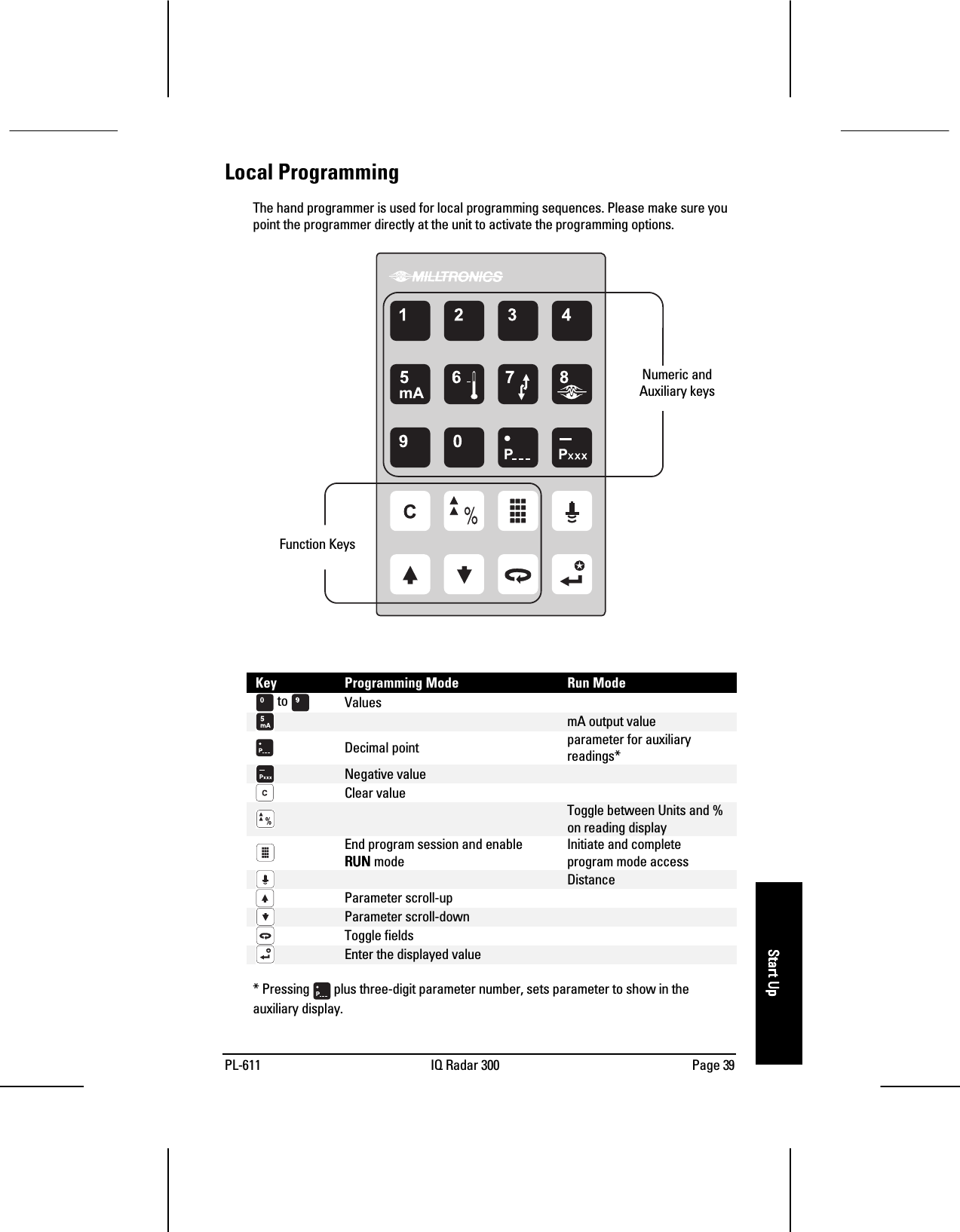
![Page 38 IQ Radar 300 PL-611Start UpStart UpStart UpStart UpProgrammingYou can activate the PROGRAMPROGRAMPROGRAMPROGRAM mode at any time and set parameters to suit theapplication and/or user preferences. Programming can be carried out locally using thehand programmer or remotely through the optional Dolphin Plus/RS-485 interface. Thesystem responds to both types of programming.The instruction examples in this manual use icons from the hand programmer.Dolphin PlusDolphin Plus is a user interface program designed to configure the IQ Radar 300 from alaptop or a desktop PC. With Dolphin Plus you can modify parameter values in real time,view process values in graphic form on screen, save profiles, and generate instrumentconfiguration reports. Dolphin Plus software is purchased separately. Please contactyour Milltronics representative.Hand ProgrammerThe programmer is a sturdy, hand-held, programming unit offering immediate access tothe configuration parameters. Point programmer at the IQ Radar 300 display window(maximum distance 15cm [6”]) and press the buttons in the required sequence.displayhand programmerDolphin Plus programminginterface](https://usermanual.wiki/Siemens-Canada-Siemens-Milltronics-Process-Instruments/IQ300/User-Guide-132603-Page-36.png)
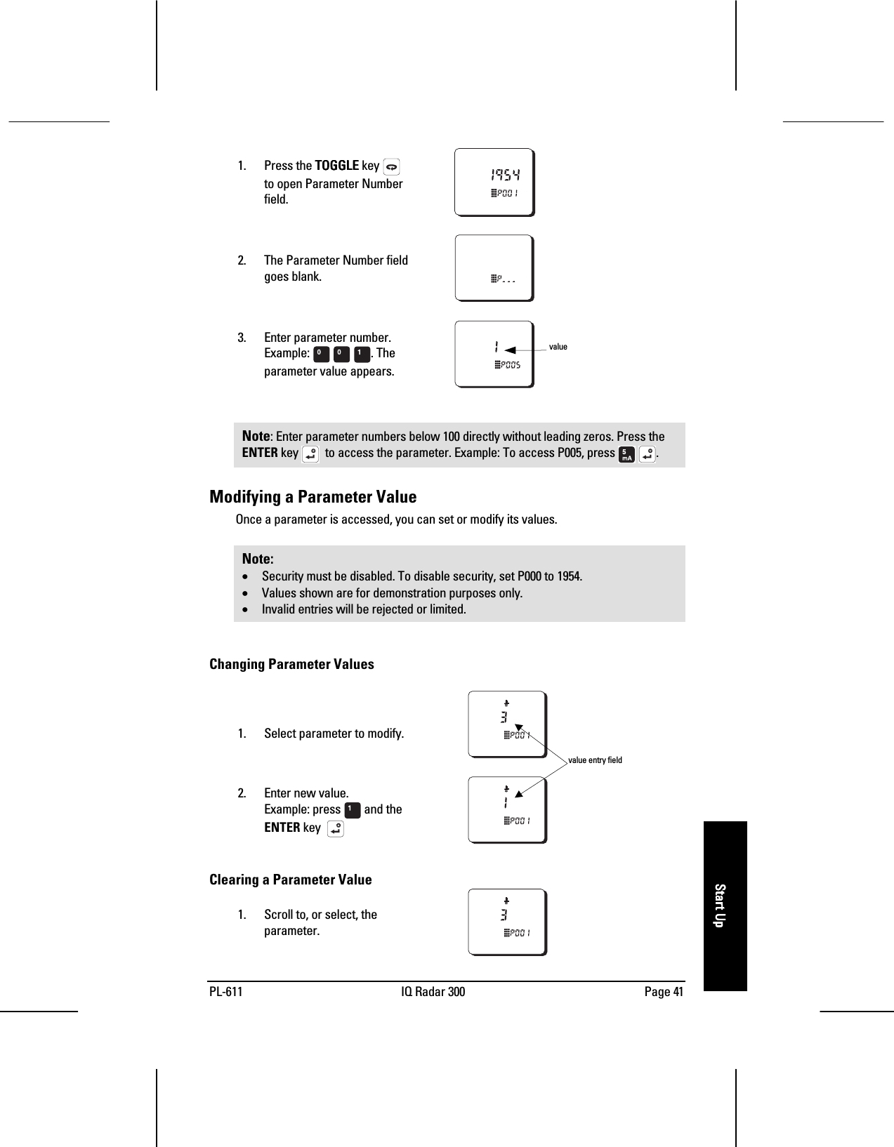
![Page 40 IQ Radar 300 PL-611Start UpStart UpStart UpStart UpAccessiiiing Program ModeNoteNoteNoteNote: Values shown are for demonstration purposes only.1. The unit starts in RUNRUNRUNRUNmode and readingscorrespond to existingsettings.2. Press the PROGRAMPROGRAMPROGRAMPROGRAM key to activate thePROGRAMPROGRAMPROGRAMPROGRAM mode. Initialprogram starts at P001.Accessing a ParameterThe parameter settings configure the units to a specific use. There are two ways toaccess parameter after you have pressed the PROGRAMPROGRAMPROGRAMPROGRAM key: Scroll Access and DirectAddress.Scroll AccessIn PROGRAMPROGRAMPROGRAMPROGRAM mode, you can scroll through the parameters sequentially, and in eitherdirection until you reach the required parameter. [scrolling range??]1. Press ARROWARROWARROWARROW keys to scroll up ordown.Direct AccessIn PROGRAMPROGRAMPROGRAMPROGRAM mode, you can access a parameter directly by entering its number.](https://usermanual.wiki/Siemens-Canada-Siemens-Milltronics-Process-Instruments/IQ300/User-Guide-132603-Page-38.png)

![PL-611 IQ Radar 300 Page 47OperationOperationOperationOperationAnalog OutputThe IQ Radar 300 can be programmed to provide an analog output (P200) of 0 to 20, or 4to 20, mA, and for proportional or inverse span.ProgrammingWhen the unit is put into PROGRAMPROGRAMPROGRAMPROGRAM mode, the analog output level holds its prior value ifthe mA output function is not common output or if HART is not the communicationprotocol. [please verify]RunThe analog output responds in the following manner:*reference value only. mA level limited by near blanking.0 and 100% are percentage of full scale reading (m, cm, mm, ft, in).](https://usermanual.wiki/Siemens-Canada-Siemens-Milltronics-Process-Instruments/IQ300/User-Guide-132603-Page-45.png)
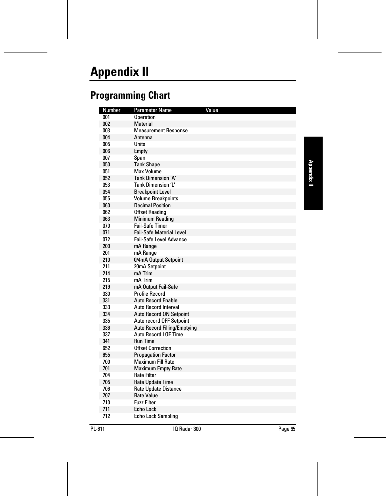
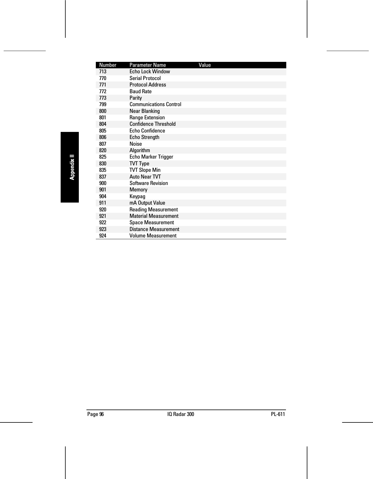
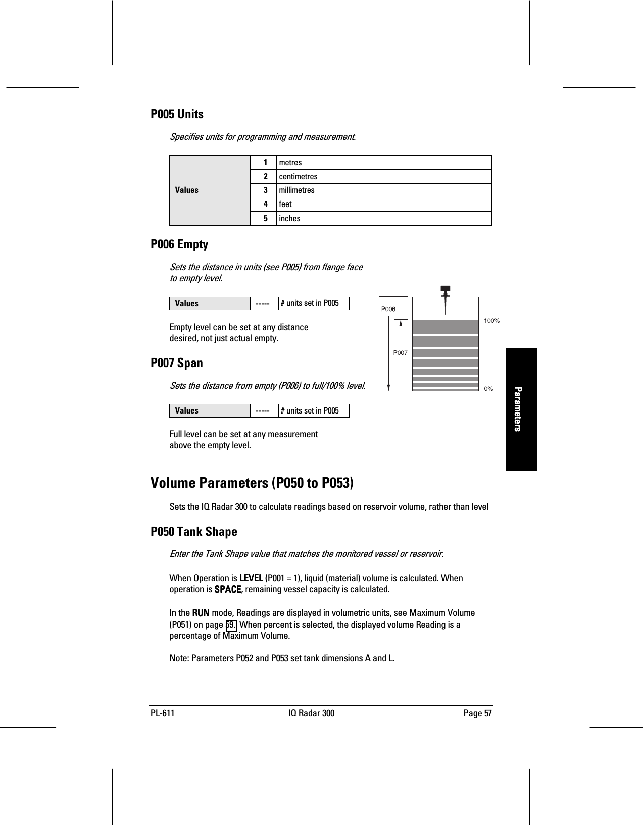
![PL-611 IQ Radar 300 Page 55ParametersParametersParametersParametersParameter DescriptionsThe parameters are the programmable features of the IQ Radar 300. Adjust the valuesettings on the parameters to configure the unit.The parameter tables show the values you need to enter in bold type, followed byadditional information when necessary. The pre-set values are the unit’s factory settingsthat may need alteration for specific applications.Press the PROGRAM key to access the parameter settings. [Tim: do you want toindicate the default values?]P000 LockSecures the IQ Radar 300 from changes.1954 Lock off: programming permittedValue other Lock activated: programming securedTo access this parameter directly, press 000 and enter any value other than 1954 tosecure the programming lock. The PROGRAM mode is active for viewing only. Tounlock, access this parameter and enter 1954.WARNING: Use this lock as backup security only. It uses a fixed value whichcan be discovered by unauthorized personnel.Quick Start Parameters (P001 to P007)Parameters P001 to P007 are the main settings that apply to all applications and get thesystem operational.P001 OperationDetermines the mode of measurement.1Level: material level referenced to empty distance (P006)2Space: space to material level referenced from span (P007)Values3Distance: distance to target referenced from the flange faceLevel (a.k.a. volume)(P001 = 1)Space (a.k.a ullage)(P001 = 2)Distance(P001 = 3)](https://usermanual.wiki/Siemens-Canada-Siemens-Milltronics-Process-Instruments/IQ300/User-Guide-132603-Page-53.png)
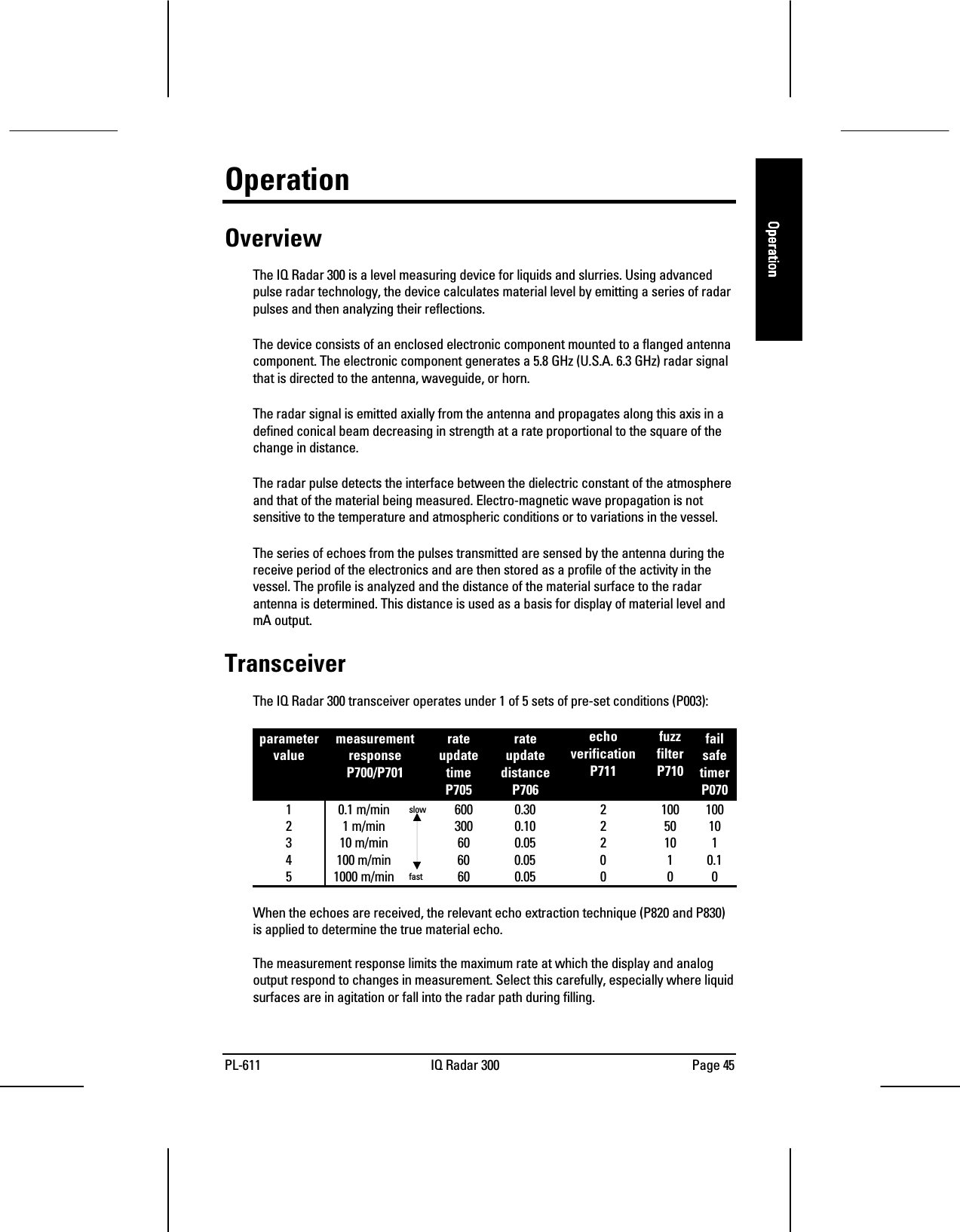
![Page 56 IQ Radar 300 PL-611ParametersParametersParametersParametersP002 MaterialIdentifies the material being monitored.Values 1 liquids or slurriesP003 Measurement ResponseSets the reaction speed of the unit to the measurement changes in the target range.measurementresponseP700/P701rateupdatetimeP705rateupdatedistanceP706fuzzfilterP710echoverificationP711failsafetimerP0701 0.1m/minute slow 600 secs 0.30 m 21001002 1m/minute 300 secs 0.10m 250103 10m/minute 60secs 0.05m 21014 102m/minute 60secs 0.05m 010.1Values5 1020m/minute fast 60secs 0.05m 000Set P003 to a measurement response just faster than the greater measurement of themaximum filling or emptying rate.If the IQ 300 cannot keep up with the rate of level change, select a faster rate. If thereading bounces around an average value, select a slower rate. In general, reliability istraded for speed. Noisy applications or those with agitators tend to be more manageableat slower response rates, as these make use of filtering, echo verification, and longerfail-safe delay.• filter: averages successive measurements to filter out false echoes• echo verification: discriminates between agitator blades in motion (spurious noise) andthe target surface (true echo)• fail-safe timer: establishes the period from the time a loss of echo (LOE) starts until thefail-safe default (P071) is triggered. The P003 pre-set timer value can be overridden byP070.P004 AntennaIdentifies antenna configuration. [Tim: is this final?]240 factory241 rod + 50mm extension242 rod + 100mm extensionValues243243243243 rod + 150mm extension (50 + 100mm)Setting this parameter automatically configures the offset correction, P652.Horn antennas and waveguide/horn combinations will come from the factory with P652pre-set and P004 set to 240. [still ok?]](https://usermanual.wiki/Siemens-Canada-Siemens-Milltronics-Process-Instruments/IQ300/User-Guide-132603-Page-54.png)
![Page 60 IQ Radar 300 PL-611ParametersParametersParametersParametersP054 Breakpoint LevelsWhen the tank shape is too complex for any of the pre-configured shapes, you canspecify the volume based on segment.Primary Index globalSecondary Index breakpointValues Range: 0.000 to 9999 in unitsRelated Parameters • P055 Volume Breakpoints (Universal Volume Calculation)Enter up to 10 level breakpoints (where volume is known) if P050 = 9 [verify]Entering a Level Breakpoint1. Open parameter P054.2. Enter a breakpoint in measurement units.3. Match each breakpoint to the same index value for P055.P055 Volume Breakpoints (Universal Volume Calculation)Each segment defined by the level breakpoints (P055) requires a volume to allow the IQ300 to make the level-to-volume calculations.Primary Index globalSecondary Index breakpointRange: 0....000 to to to to 9999 in unitsValues Pre-set: 0.000Related Parameters • P054 Volume Breakpoints (Universal Volume Calculation)Typical volume calculations:Cone CylinderV = (1/3)πr2hV = πr2hEntering a Volume Breakpoint1. Open parameter P0552. For each index enter a volume3. Match each volume to the same index value for P054](https://usermanual.wiki/Siemens-Canada-Siemens-Milltronics-Process-Instruments/IQ300/User-Guide-132603-Page-58.png)
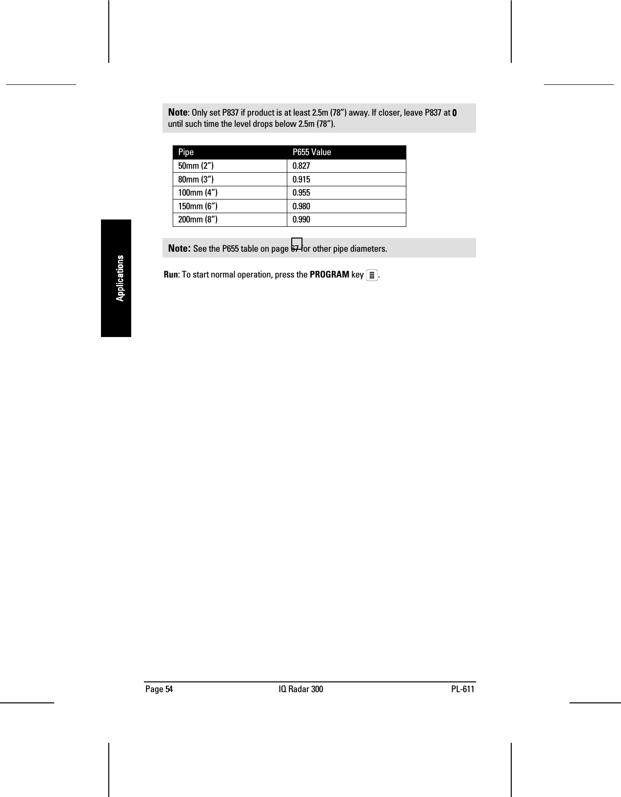
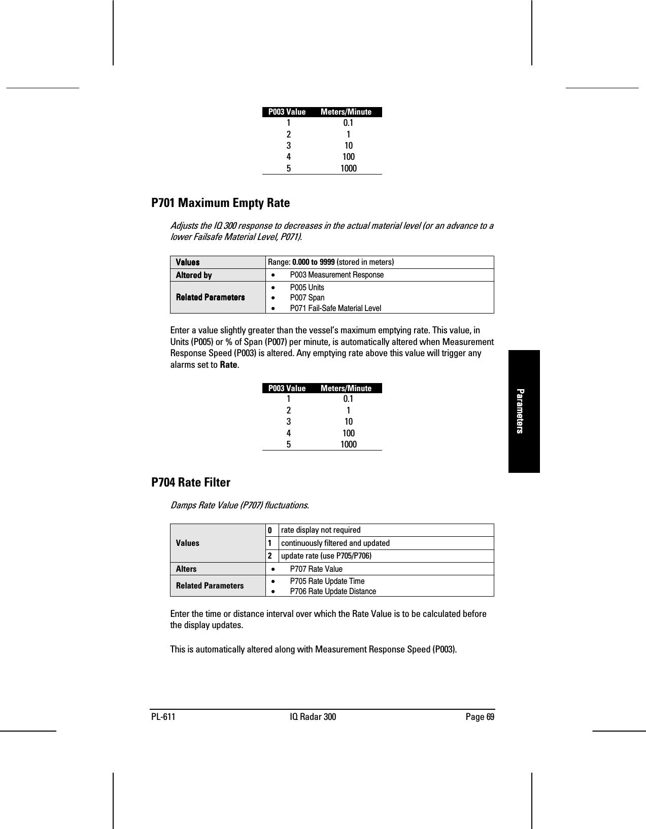
![Page 68 IQ Radar 300 PL-611ParametersParametersParametersParametersPipe Size (i.d.) Propagation Factor50mm (2”)0.82780mm (3”)0.915100mm (4”)0.955150mm (6”)0.98020 mm (8”)0.990Consult the factory for other sizes and propagation factor numbers.[Tim: who at thefactory?]Note: : : : For waveguide antennas used as stillpipes, this value is on the product tag.The propagation factor is constant for a givenpipe diameter, or can be determined bycomparing the radar distance reading to theactual process material distance (measuredfrom the face of the IQ 300 flange).actual distance = p.f.IQ 300 distanceUsing the readings shown:10.42m = 0.82712.6mEnter the propagation factor: 0.8270.8270.8270.827Rate ParametersThese parameters determine how material level changes are reported.P700 Maximum Fill RateAdjusts the IQ 300 response to increases in the actual material level (or an advance to ahigher Failsafe Material Level, P071).ValuesValuesValuesValues Range: 0.000 to 9999 (stored in meters)Altered byAltered byAltered byAltered by • P003 Measurement ResponseRelated ParametersRelated ParametersRelated ParametersRelated Parameters• P005 Units• P007 Span• P071 Fail-Safe Material LevelEnter a value slightly greater than the maximum vessel filling rate. This value, in Units(P005) or % of Span (P007) per minute, is automatically altered when Maximum ProcessSpeed (P003) is altered.](https://usermanual.wiki/Siemens-Canada-Siemens-Milltronics-Process-Instruments/IQ300/User-Guide-132603-Page-66.png)
![PL-611 IQ Radar 300 Page 75ParametersParametersParametersParametersRelated Parameters • P804 Confidence ThresholdP806 Echo StrengthDisplays the strength of the selected echo, in dB above 1 µV rms.Values (view only) Display: 0 to 9P807 NoiseDisplays the average and peak ambient noise (in dB above 1 µV RMS) being processed.x = average (-9 to 99)Values (view only) y = peak (-9 to 99)The noise level is a combination of transient noise and electrical noise (receivingcircuitry).Algorithm ParametersP820 AlgorithmSelects the algorithm to be applied to the echo profile in order to extract the true echo.[verify chart]1ALF = flat AAAArea, LLLLargest, and FFFFirst average2A = flat AAAArea only3L = flat LLLLargest only4F= flat FFFFirst only5AL = flat AAAArea and LLLLargest average6AF = flat AAAArea and FFFFirst average7LF = flat LLLLargest and FFFFirst average8bLF = smooth LLLLargest or FFFFirst9bL = smooth LLLLargest onlyValues10 bF = smooth FFFFirst onlySelect 1 for most applications and all mounting locations except the center of the vessel.Select 6 for the center of the vessel mounting location and for still pipes and waveguideantennas used as stillpipes.](https://usermanual.wiki/Siemens-Canada-Siemens-Milltronics-Process-Instruments/IQ300/User-Guide-132603-Page-73.png)
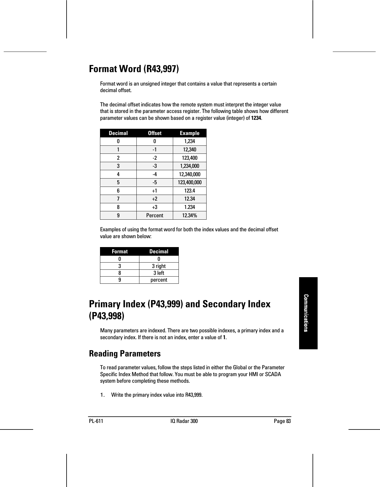
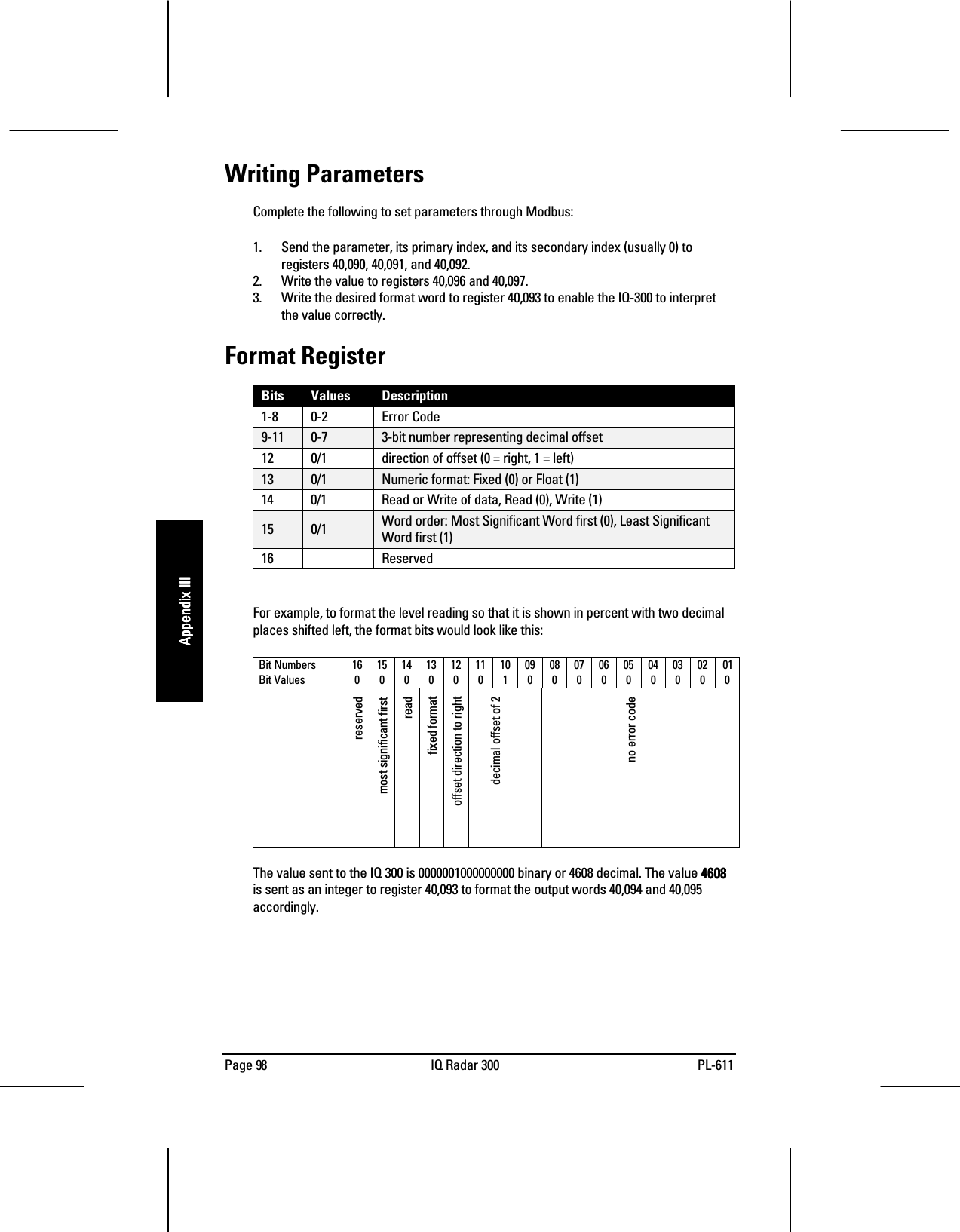
![Page 84 IQ Radar 300 PL-611CommunicationsCommunicationsCommunicationsCommunicationsThis is a value between 0 and 40 which specifies the input or output indexed by theparameter.Examples (P920, primary index 1)2. Write the secondary index value into R43,998.This is a value between 0 and 40 that specifies the secondary index on the parameter.This value is usually 0.3. Write the desired format value into R43,997 [such as??].4. Read the value from the appropriate parameter register.Types of values are:• Numeric Values on page 85.• Split Values on page 85.• Text Messages on page 86.A value of 22,222 indicates that an error has occurred. Specify a different format typeand try again.Writing ParametersThe method of writing parameters is similar to the method of reading them. Becomefamiliar with Reading Parameters, page 83, before attempting to write any parameters.Writing parameter values to the IQ 300:1. Write the primary index value into R43,999.2. Write the secondary index value into R43,998.3. Write the desired format value into R43,997.4. Write the value to the appropriate parameter register.](https://usermanual.wiki/Siemens-Canada-Siemens-Milltronics-Process-Instruments/IQ300/User-Guide-132603-Page-82.png)