Siemens Canada Siemens Milltronics Process Instruments IQ300 User Manual Manual Title
Siemens Canada Ltd. - Siemens Milltronics Process Instruments Manual Title
users manual

PL-611 IQ Radar 300 Page 3
General Information
Table of Contents
Table of Contents
Table of ContentsTable of Contents
Table of Contents................................
................................................................
................................................................
................................................................
................................................................
................................................................
...................................................
......................................
................... 3
33
3
General Information
General InformationGeneral Information
General Information ................................
................................................................
................................................................
................................................................
................................................................
................................................................
..............................................
............................
.............. 7
77
7
The Manual......................................................................................................................................7
IQ Radar 300.....................................................................................................................................8
IQ Radar 300 Applications............................................................................................................8
IQ Radar 300 Approvals and Certificates...........................................................................................8
IQ Radar 300 Communication Systems ....................................................................................9
Optional SmartLinx® cards.....................................................................................................................9
Specifications
SpecificationsSpecifications
Specifications ................................
................................................................
................................................................
................................................................
................................................................
................................................................
.......................................................
..............................................
....................... 11
1111
11
IQ Radar 300...................................................................................................................................11
Installation
InstallationInstallation
Installation................................
................................................................
................................................................
................................................................
................................................................
................................................................
.............................................................
..........................................................
............................. 15
1515
15
Location...........................................................................................................................................15
Dimensions: IQ Radar 300 with Rod Antenna.......................................................................16
Dimensions: Threaded Rod .......................................................................................................17
Dimensions: Horn .........................................................................................................................18
Dimensions: Waveguide Extension.........................................................................................19
Dimensions: Sanitary Horn........................................................................................................20
Dimensions: Sanitary Rod..........................................................................................................21
Dimensions: Waveguide.............................................................................................................22
Dimensions: Flanges ...................................................................................................................23
Mounting.........................................................................................................................................24
Threaded Rod Antenna........................................................................................................................ 25
Rod Assembly................................................................................................................................26
Rod Extension Requirements............................................................................................................. 26
Mounting: Rod Assembly ...........................................................................................................27
Mounting: Manhole Covers.......................................................................................................28
Mounting: Horn Antennas..........................................................................................................28
Mounting: Waveguide Antenna...............................................................................................29
Mounting: Stillpipe or Sidepipe ................................................................................................30
Smoothness ............................................................................................................................................ 30
Mounting: Horn with Waveguide Extensions.......................................................................31
Mounting: Sanitary Mounting...................................................................................................31
Mounting: Location ......................................................................................................................32
Polarization Effect ................................................................................................................................. 32
False Reflections ................................................................................................................................... 32
Interconnection
InterconnectionInterconnection
Interconnection ................................
................................................................
................................................................
................................................................
................................................................
................................................................
....................................................
........................................
.................... 33
3333
33
IQ Radar 300 Terminal Block.............................................................................................................. 33
IQ Radar 300 Wiring.............................................................................................................................. 34
Communications Installation.....................................................................................................35
Wiring Guidelines.................................................................................................................................. 35
Port 1: RS-485 ......................................................................................................................................... 35
Port Configuration................................................................................................................................. 36

Page 4 IQ Radar 300 PL-611
General Information
Start Up
Start UpStart Up
Start Up................................
................................................................
................................................................
................................................................
................................................................
................................................................
................................................................
................................................................
..................................
....
.. 37
3737
37
Overview.........................................................................................................................................37
Run Mode Display ................................................................................................................................. 37
Program Mode Display........................................................................................................................ 37
Programming .......................................................................................................................................... 38
Local Programming............................................................................................................................... 39
Operation
OperationOperation
Operation
................................
................................................................
................................................................
................................................................
................................................................
................................................................
..............................................................
............................................................
.............................. 45
4545
45
Overview.........................................................................................................................................45
Transceiver ....................................................................................................................................45
Loss of Echo...................................................................................................................................46
Blanking ..........................................................................................................................................46
Analog Output................................................................................................................................47
Programming .......................................................................................................................................... 47
Run............................................................................................................................................................. 47
Volume...................................................................................................................................................... 48
Fail-Safe ................................................................................................................................................... 48
Run/Program..................................................................................................................................48
Application Examples
Application ExamplesApplication Examples
Application Examples................................
................................................................
................................................................
................................................................
................................................................
................................................................
..........................................
....................
.......... 49
4949
49
Application Example: Asphalt in Storage Tank....................................................................49
Application Example: Horizontal Tank with Volume...........................................................50
Application Example: Juice Batch Tank with Sanitary Horn Antenna..........................51
Application Example: Sliding Waveguide on Anaerobic Digesters ...............................52
Application Example: Stillpipe...................................................................................................53
Parameter Descriptions
Parameter DescriptionsParameter Descriptions
Parameter Descriptions ................................
................................................................
................................................................
................................................................
................................................................
................................................................
......................................
............
...... 55
5555
55
Quick Start Parameters (P001 to P007) ...........................................................................................55
Volume Parameters (P050 to P053) .................................................................................................. 57
Display and Reading Parameters (P060 to P063) ......................................................................... 61
Fail-Safe Parameters (P070 to P072) ............................................................................................... 62
mA Parameters (P200 to P219) .......................................................................................................... 62
Independent mA Setpoints Parameters (P210 and P211) .......................................................... 63
Profile Record Parameters (P330 to P337) ..................................................................................... 64
Auto Record ON and OFF Setpoint Parameters (P334 to P337) ............................................... 66
Installation Records Parameter ........................................................................................................ 67
Range Calibration Parameters .......................................................................................................... 67
Rate Parameters.................................................................................................................................... 68
Measurement Verification Parameters .......................................................................................... 70
Communication Parameters............................................................................................................... 72
Echo Processing Parameters ............................................................................................................ 74
Algorithm Parameters.......................................................................................................................... 75
TVT Adjustment Parameters.............................................................................................................. 76
P837 Auto Near TVT ............................................................................................................................. 78
Test Parameters .................................................................................................................................... 78
Communications: Modbus Register Map
Communications: Modbus Register MapCommunications: Modbus Register Map
Communications: Modbus Register Map ................................
................................................................
................................................................
................................................................
........................................
................
........ 81
8181
81
Product ID (R40,064).....................................................................................................................81
Point Data (R41,010 – R41,031)..................................................................................................81
Input/Output (R41,070 – R41,143)..............................................................................................82
mA Output (R41,110).............................................................................................................................. 82
Parameter Access (R43,997 – R46,999) ..................................................................................82

PL-611 IQ Radar 300 Page 5
General Information
Format Word (R43,997)................................................................................................................83
Primary Index (P43,999) and Secondary Index (P43,998) ..................................................83
Reading Parameters............................................................................................................................. 83
Writing Parameters .............................................................................................................................. 84
Communications: Data Types
Communications: Data TypesCommunications: Data Types
Communications: Data Types ................................
................................................................
................................................................
................................................................
............................................................
........................................................
............................ 85
8585
85
Numeric Values ............................................................................................................................85
Split Values ....................................................................................................................................85
Text Messages..............................................................................................................................86
Error Handling
Error HandlingError Handling
Error Handling ................................
................................................................
................................................................
................................................................
................................................................
................................................................
......................................................
............................................
...................... 87
8787
87
Modbus Responses .....................................................................................................................87
Error Handling ...............................................................................................................................87
Troubleshooting
TroubleshootingTroubleshooting
Troubleshooting ................................
................................................................
................................................................
................................................................
................................................................
................................................................
...................................................
......................................
................... 89
8989
89
Communication Troubleshooting.............................................................................................89
Generally.................................................................................................................................................. 89
Specifically=89
Operation Troubleshooting........................................................................................................91
Maintenance
MaintenanceMaintenance
Maintenance
................................
................................................................
................................................................
................................................................
................................................................
................................................................
........................................................
................................................
........................ 92
9292
92
Appendix I
Appendix IAppendix I
Appendix I ................................
................................................................
................................................................
................................................................
................................................................
................................................................
.............................................................
..........................................................
............................. 93
9393
93
Alphabetical Parameter List......................................................................................................93
Appendix II
Appendix IIAppendix II
Appendix II ................................
................................................................
................................................................
................................................................
................................................................
................................................................
............................................................
........................................................
............................ 95
9595
95
Appendix III
Appendix IIIAppendix III
Appendix III ................................
................................................................
................................................................
................................................................
................................................................
................................................................
...........................................................
......................................................
........................... 97
9797
97
Single Parameter Access (SPA) ..............................................................................................97
Reading Parameters....................................................................................................................97
Writing Parameters .....................................................................................................................98
Format Register.............................................................................................................................98
Error Codes ....................................................................................................................................99
Appendix IV
Appendix IVAppendix IV
Appendix IV................................
................................................................
................................................................
................................................................
................................................................
................................................................
.........................................................
..................................................
......................... 101
101101
101
Temperature De-rating .............................................................................................................101
Rod Antenna ANSI Hole Pattern, 150#, ................................................................................102
Rod Antenna DN Hole Pattern, PN169, 10 ...............................................................................102
Rod Antenna Threaded Connection......................................................................................103
Rod Antenna Sanitary Connection ........................................................................................103
Horn Antenna or Wave Guide – ANSI Hole Pattern, 150#..............................................104
Horn Antenna or Wave Guide DN Hole Pattern, PN1612 .................................................104
Horn Antenna Sanitary Connection ......................................................................................105
Appendix V
Appendix VAppendix V
Appendix V ................................
................................................................
................................................................
................................................................
................................................................
................................................................
..........................................................
....................................................
.......................... 107
107107
107
BZT Approval – English ............................................................................................................107
BZT Approval – German Original Text .................................................................................108

Page 6 IQ Radar 300 PL-611
General Information

PL-611 IQ Radar 300 Page 7
General Information
General Information
General Information
General Information
General Information
The Manual
Refer to this manual for proper installation and operation of your IQ Radar 300. The
margin tabs denote the sections, and each section presents IQ 300 features. Please read
all sections before operating the IQ 300.
Installation: Installing the IQ 300 and the interconnection instructions.
Start-up
Start-upStart-up
Start-up: Operating the keypad, programming the unit, and reading the
display.
Operation:
::: IQ 300 operating instructions.
Applications: Application examples and practical use.
Parameters: Available parameters and a description of function and use.
Please read this section and familiarize yourself with the
parameters available to you and get your IQ 300 working to its
fullest.
Communications: Configure communication settings.
Troubleshooting: Responses to common installation and application problems.
Appendices: An alphabetical cross-reference of the parameters and their
numbers, a record sheet for jotting down parameter values, a
Temperature De-rating Chart, and a list of approvals and
certificates.

Page 8 IQ Radar 300 PL-611
General Information
General Information
General Information
General Information
IQ Radar 300
The IQ Radar 300 is to be used only in the manner outlined in this manual.
IQ 300 is a versatile process level monitoring instrument using advanced pulse radar
techniques. The unit consists of an electronic component coupled to the antenna and
process connection.
This device can handle virtually all of your pump control and level monitoring needs,
often replacing expensive PLCs and integrating into a SCADA system for a fraction of
the cost of competitive systems.
IQ Radar 300 Applications
• liquids, slurries
• process temperatures up to 200°C
• vacuum and pressurized vessels
IQ Radar 300 Approvals and Certificates
• safety and radio
• hazardous area
Note: See Specifications on page 11 for an approvals listing and Appendix V on page
107 for approvals documentation.
PL-611 IQ Radar 300 Page 9
General Information
General Information
General Information
General Information
IQ Radar 300 Communication Systems
The IQ Radar 300 is a level monitoring instrument using advanced pulse radar
techniques that communicates component and system status to a Supervisory Control
and Data Acquisition (SCADA) system.. [graphic will be revised]
The standard IQ 300 supports Modbus communications on board and Hear and Profibus
PA via add-on cards.
Dolphin
Dolphin is a proprietary Milltronics protocol designed to be used with Dolphin Plus. For
more information on Dolphin Plus, or to obtain a copy of the software, contact your
Milltronics representative.
Modbus
Modbus is an industry standard protocol used by SCADA and HMI systems, and uses the
IQ Radar 300’s RS-232 ports to communicate. For a description of the Modbus protocol,
contact your local Schneider representative.
Optional SmartLinx®Cards
The standard IQ Radar 300 unit may also be enhanced with Milltronics’ SmartLinx®
communication modules that interface with popular industrial communication systems.
This manual only describes the built-in communications. For more information on
SmartLinx, please consult the appropriate SmartLinx manual.
radio modem
IQ 300
unit

Page 10 IQ Radar 300 PL-611
General Information
General Information
General Information
General Information

PL-611 IQ Radar 300 Page 11
Specifications
Specifications
Specifications
Specifications
Specifications
Milltronics makes every attempt to ensure the accuracy of these specifications but
reserves the right to change them at any time. Contact your Milltronics representative
for the most recent specifications.
IQ Radar 300
Power:
• 100/115/200/230 ±15% V ac1, 50/60 Hz, 15 VA
Fuse:
• FU1, 2AG type, slow blow, .25 A, 250V
Interface:
• analog output: optically-isolated 0/4-20 mA into 750 Ω max, 0.02
mA resolution
• Dolphin/RS-485 link: refer to Dolphin Plus product specification
• programmer link: infrared receiver (refer to Programmer
specification on page 13)
• display (local): backlit, alphanumeric, and multi-graphic liquid
crystal for readout and entry
Performance:
• frequency: 5.8 GHz (U.S.A. 6.3 GHz)
• accuracy at 20° C: better than ±0.3% of range from 1 to 15m
• temperature drift: <±0.5% of range from –40 to 60° C (-40 to 392° F)
• measuring range: 0.4m to 15m
• repeatability: ± 10mm
• fail-safe: mA programmable high, low or hold upon LOE
condition
Mechanical:
Process Connections (Please refer to Appendix IV) for pressure/temperature limitations.)
• flat faced flanges: 316 stainless steel, 2”, 3”, 4”, 50mm, 80mm,
100mm. Bolt hole pattern to ANSI and DIN
types.
• threaded connection: 316 stainless steel, 1-1/2” or 2”, NPT, BSP
• sanitary connection: 316 stainless steel, 2”, 3”, or 4” tri-clamp
1 Factory set – see device nameplate.

Page 12 IQ Radar 300 PL-611
Specifications
Specifications
Specifications
Specifications
Antennas:
• dielectric rod: Teflon®2 (PTFE)
Ultra-high molecular weight Polyethylene
(UHMW-PE3)
Length 41cm (16.3”), including integral gasket
• horn: 316 stainless steel
diameters 100mm (4”), 150mm (6”),
200mm (8”)
emitter cone PTFE or UHMW-PE4
waveguide extensions optional
• waveguide: 316 stainless steel
emitter cone PTFE or UHMW-PE4
Sanitary Antennas (FDA approved materials):
• dielectric rod: one piece UHMW-PE4, optional PTFE
2”, 3”, 4” tri-clamp connection
• horn: 304 stainless steel (316 special order)
horn with integral 4” tri-clamp
connection PTFE emitter
Enclosure (electronic):
• construction: aluminum, epoxy coated
• conduit: 2 x 1/2" NPT or PG 16 entry
• ingress protection: Type 6 / NEMA 6, IP-67
Weight:
• 6.5 kg (14.3 lb) with 2"/150 psi flange
• weight will vary with flange size and rating
Environmental:
• location: indoor/outdoor
• altitude: 2000m max
• ambient temperature: -40 to 60° C (-40 to 140° F)4
• relative humidity: suitable for outdoor (Type 6/NEMA 6/IP 67
enclosure)
• installation category: II
• pollution degree: 4
Process
• material dielectric: εr > 1.8
For εr < 3, you should use a waveguide antenna
or stillpipe. (See Mounting: Waveguide Antenna
on page 29 or Mounting: Stillpipe or Sidepipe on
page 30.)
2 Teflon is a registered trademark of Du Pont.
3 Not available for CENELEC EEx approval.
4 See Temperature De-rating on page 97 and Approvals on page 13.

PL-611 IQ Radar 300 Page 13
Specifications
Specifications
Specifications
Specifications
• temperature: UHMW-PE -40 to 80°C (-40 to 176°F)
PTFE -40 to 200°C (-40 to 392°F)5
• pressure (vessel): dependant on process connection type and
temperature. Refer to Appendix IV on page 101
for charts.
Approvals (refer to device nameplate)
• safety: CSANRTL/C, CE, FM
• radio: BAPT, Industry Canada, FCC
Hazardous areas:
• IQ Radar 300: Cenelec/Sira6, EEx de IIB+H2 T6 (Note: antenna
may be used in Zone 0 environments).
FM (USA) Class I, Div 1, Group A, B, C, D. Class
II/III, Div. 1, Group E, F, G(Class I, Zone 1 IIC T6)
CSA Class I/II, Div. 1, Group B, C, D, E,F, G.CE,
CSANRTL/C FM (non-hazardous)
Canadian Registration Number (CRN) for pressure fittings:7
• Ontario, British Columbia, Alberta: OF6494.512
• others pending
• 3A Sanitary
Note: Contact Milltronics for complete and up-to-date list of approvals.
Programmer (remote keypad)
• enclosure: general purpose
67mm w x 100mm h x 25mm d
(2.6" w x 4" h x 1" d)
• ambient temperature: -20 to 50° C (-5 to 122° F)
• interface: proprietary infrared pulse signal
• power: 9V battery (ANSI/NEDA 1604, PP3 or equivalent)
• weight: 150g (0.3 lb)
5 See Temperature De-rating on page 97 and Approvals on page 13.
6 Approved for PTFE material only
7 All process connections except for the sliding waveguide

Page 14 IQ Radar 300 PL-611
Specifications
Specifications
Specifications
Specifications
PL-611 IQ Radar 300 Page 15
Installation
Installation
Installation
Installation
Installation
Location
Note:
• Installation shall only be performed by qualified personnel and in accordance with
local governing regulations.
• This product is susceptible to electrostatic shock. Follow proper grounding
procedures.
• Do not mount in direct sunlight without the use of a sun shield.
Warning: For vessels with conical or parabolic tops, avoid mounting the unit at
the centre.
Otherwise, the concavity of the top can focus echoes into the centre,
giving false readings.
Conical
ConicalConical
Conical
Flat
FlatFlat
Flat
Parabolic
ParabolicParabolic
Parabolic
Page 16 IQ Radar 300 PL-611
Installation
Installation
Installation
Installation
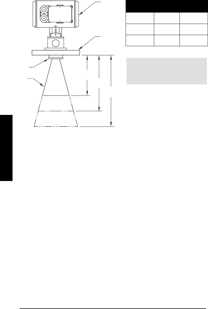
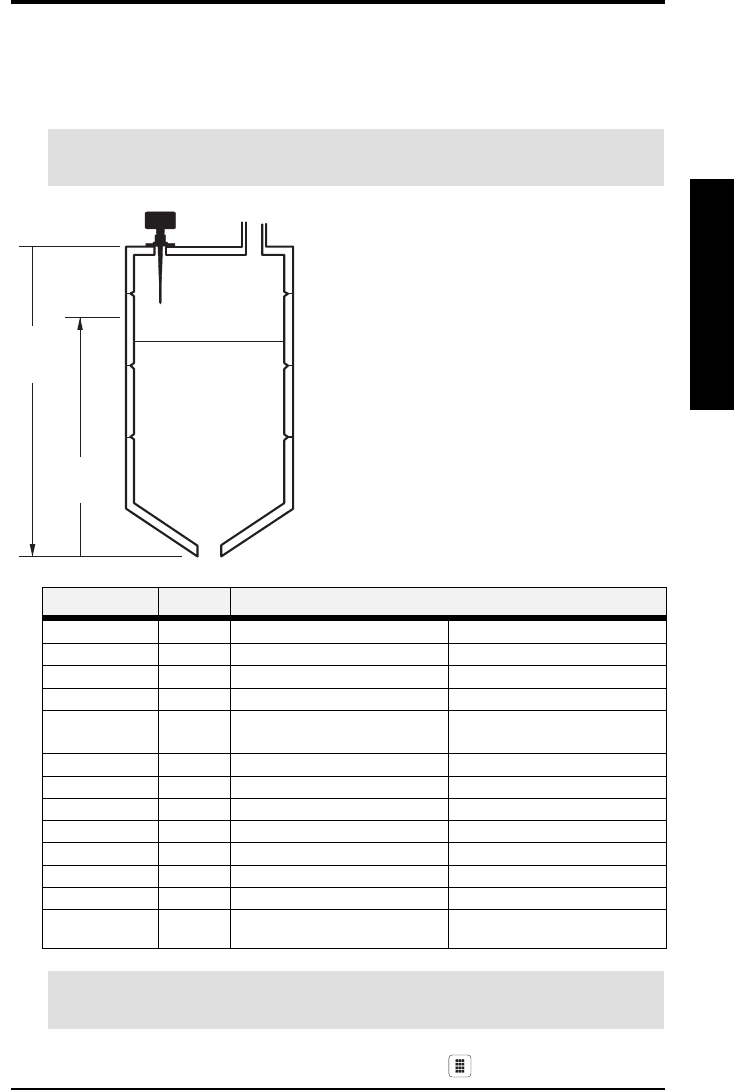
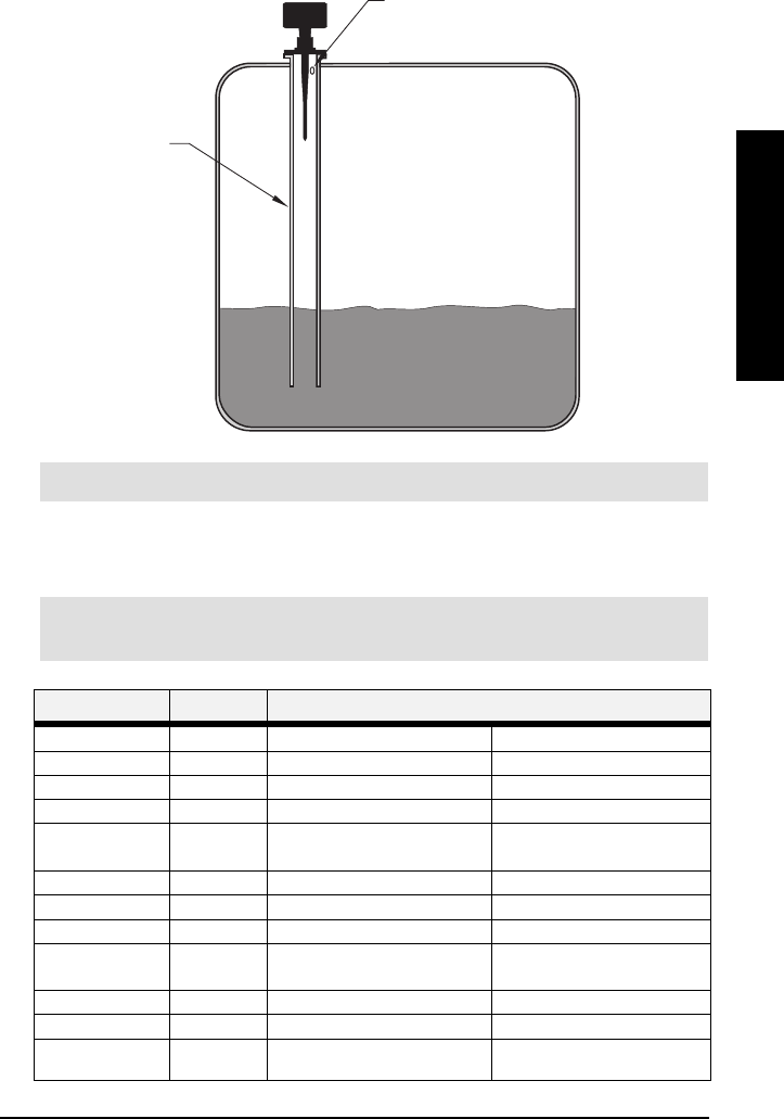
Dimensions: IQ Radar 300 with Rod Antenna
* Flange thickness 25mm (1") nominal.
** Standard length, 50 and 100mm (2” and 4") extensions available.
For information on temperature and pressure ratings, see Appendix IV on page 101.
enclosure
/
electronics
antenna
(rod)
antenna
(resonator)
flange
136mm
(5.4")
75mm
(3.0")
64mm
(2.5")
239mm
(9.4")
41mm (1.6")
183mm
(7.2")
245mm
(9.6")
100mm (4.0")
earth
connection
412mm **
(16.3")
PL-611 IQ Radar 300 Page 17
Installation
Installation
Installation
Installation
Dimensions: Threaded Rod
50mm
(2”)
100mm
(4”)
optional
extension
standard antenna
Teflon paste
(supplied)
Note:
Ingress of water or process fluids into the connecting threads
can cause reflections at the connection, appearing as false
echoes.
Apply Teflon paste to threads and tighten slowly. Ensure that
the rod sections mate securely with no gaps. Do not apply too
much Teflon paste or parts will not mate securely.
Do not use wrenches or pliers. Hand tight only.
Sealant must have εr < 3. We recommend a sealant such as
Teflon paste or silicone compound.
Page 18 IQ Radar 300 PL-611
Installation
Installation
Installation
Installation
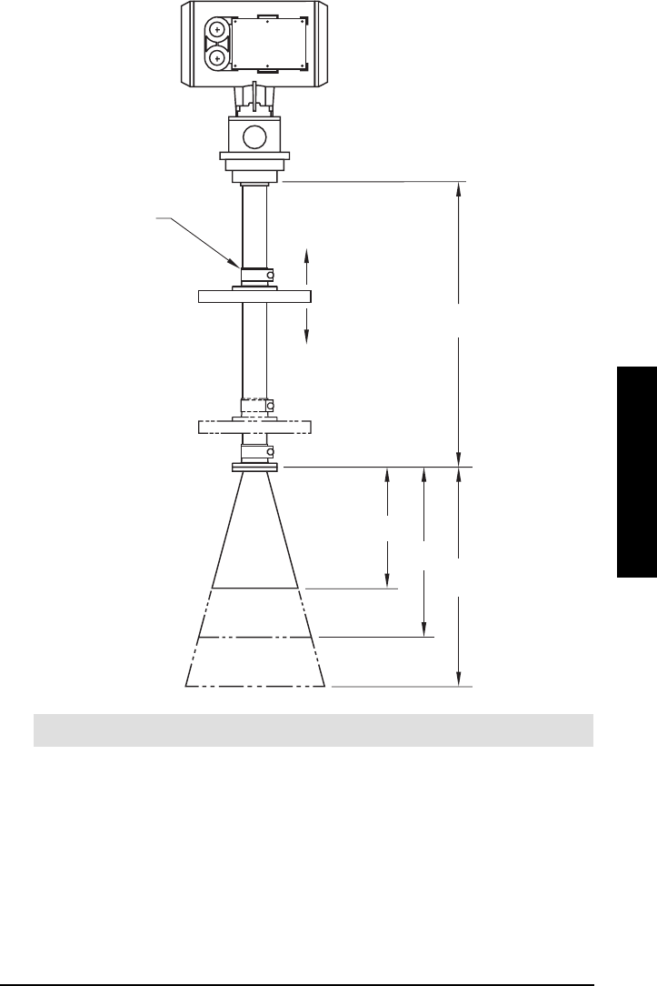
Dimensions: Horn
Nominal
Horn Size Horn O.D. Horn Height
100mm
(4”)
95.3mm
(3.75”)
131.0mm
(5.16”)
150mm
(6”)
146.0mm
(5.75”)
225.8mm
(8.89”)
200mm
(8”)
199.4mm
(7.85”)
325.1mm
(12.8”)
flange
horn
131mm
(5.16”)
225.8mm
(8.89”)
325.1mm
(12.8”)
enclosure
/
electronics
100mm
(4”)
150 mm
(6”)
200mm
(8”)
∅ 80mm
(3”)
Note: Signal amplitude increases with
horn diameter, so use the largest
practical size.
PL-611 IQ Radar 300 Page 19
Installation
Installation
Installation
Installation
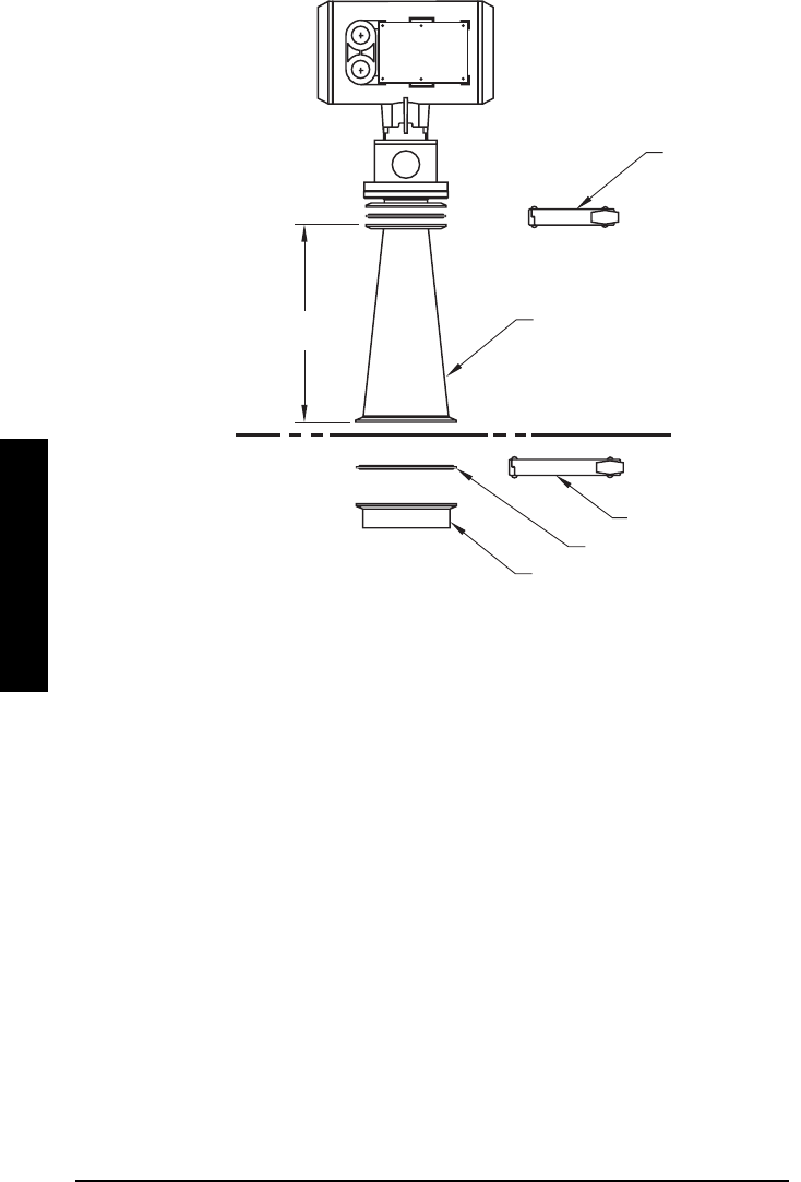
Dimensions: Waveguide Extension
Note: Maximum pressure 0.5 bar at 60° C (140° F) for sliding flange option.
Note:
Always clamp the instrument in the
same position for operation.
(see P006 on page 53).
1000mm
(40.8”)
optional sliding flange
(see flange table)
131mm (5.16”)
225mm
(8.89”)325mm
(12.8”)
Page 20 IQ Radar 300 PL-611
Installation
Installation
Installation
Installation
Dimensions: Sanitary Horn
50mm (2”) clamp
(supplied)
100mm (4”) clamp (optional)
Materials:
Materials:Materials:
Materials: standard
standardstandard
standard optional
optionaloptional
optional
horn SS 304 SS 316
ferrule SS 304 SS 316
clamp SS 304 SS 316
gasket PTFE
horn
ferrule (optional)
gasket (optional)
232mm
(9.13”)
PL-611 IQ Radar 300 Page 21
Installation
Installation
Installation
Installation
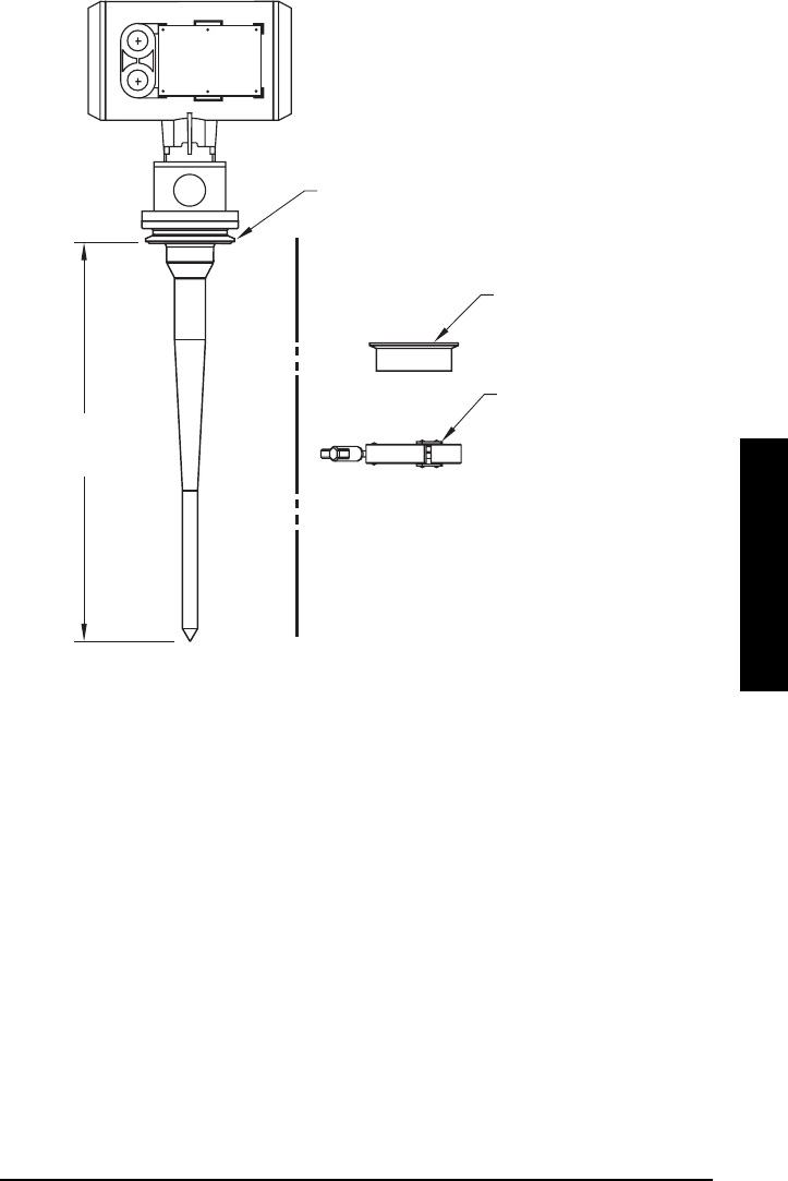
Dimensions: Sanitary Rod
50mm (2”), 80mm (3”), or 100mm (4”)
with integral gasket
Materials: SS304 standard
SS316 optional
ferrule (optional)
clamp (optional)
406mm (16”)
nominal
Page 22 IQ Radar 300 PL-611
Installation
Installation
Installation
Installation
Dimensions: Waveguide
Note
NoteNote
Note:
::: you can connect a maximum of two waveguides together.
variable
waveguide
41.4mm
(1.69”)
76.2mm
(3.0”)
min: 100mm (4.08”)
max: 6000mm (244.90”)
PL-611 IQ Radar 300 Page 23
Installation
Installation
Installation
Installation
Dimensions: Flanges
Pipe Size
Pipe SizePipe Size
Pipe Size Flange Size
Flange SizeFlange Size
Flange Size Flange
FlangeFlange
Flange
O.D.
O.D.O.D.
O.D.
Bolt Hole
Bolt HoleBolt Hole
Bolt Hole
Circle Ø
Circle ØCircle Ø
Circle Ø
Bolt Hole
Bolt HoleBolt Hole
Bolt Hole
Ø
ØØ
Ø
Number
NumberNumber
Number
of Bolts
of Boltsof Bolts
of Bolts
2”ANSI 150# 6.0”4.75”.7”4
3”ANSI 150# 7.5”6.0”.75”4
4”ANSI 150# 9.0”7.50”.75”8
6”ANSI 150# 11.0”9.50”.88”8
8”ANSI 150# 13.5”11.75”.88”8
50mm DN PN 16 165mm 125mm 18mm 4
80mm DN PN 16 200mm 160mm 18mm 8
100mm DN PN 16 220mm 180mm 18mm 8
150mm DN PN 16 285mm 240mm 22mm 8
200mm DN PN 16 340mm 295mm 22mm 12
bolt hole
bolt hole
circle
horn
/
waveguide
mounting holes
(threaded)
45°
bolt-hole
enclosure mounting holes
(threaded)
bolt hole
circle
20mm (0.8”), nominal
Page 24 IQ Radar 300 PL-611
Installation
Installation
Installation
Installation
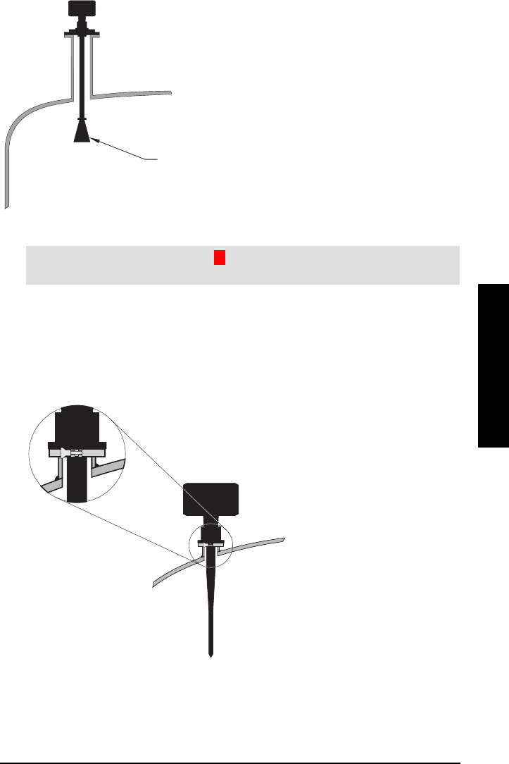
Mounting
Note:
• The straight/taper transition of the rod should extend past the standpipe/vessel
opening. Add extensions as required.
• Refer to the Rod Extension Requirements table.
* The unit in is improperly mounted. The Integral process seal MUST rest on customer flange
as in .
1/2" NPT or PG 16
conduit entry
wiring access
cover
customer flanged
standpipe to suit
tank
minimum diameter
2" / DIN 50
standpipe/vessel juncture
straight/taper transition
customer flange
integral process seal
* see below

PL-611 IQ Radar 300 Page 25
Installation
Installation
Installation
Installation
Threaded Rod Antenna
You can use 1.5” or 2” threaded process connections. There are three thread types:
NPT, BSP, and G.
Wetted Parts:
Wetted Parts:Wetted Parts:
Wetted Parts:
Metal: 316SS
Polymeric: PTFE or UHMW-PE
Internal O-ring: Viton
316 S.S.
PTFE or UHMW-PE

Page 26 IQ Radar 300 PL-611
Installation
Installation
Installation
Installation
Rod Assembly
Rod Extension Requirements
standpipe i.d. standpipe height mm (inches)*
<100 (4) 100 to 150 (4 to 6) 150 to 200 (6 to 8)
50mm (2”)n/r ** **
80mm (3”) n/r 50mm 100mm
100mm (4”) n/r 50mm 100mm
150mm (6”) n/r 50mm 100mm
>150mm (6”) n/r n/r n/r
n/r extension not required
* Consult Milltronics for assistance with standpipe sizes not listed.
** application not recommended for 50mm (2”) i.d. standpipes greater than 100mm (4”) long.
optional
extension
Note:
Ingress of water or process fluids into the connecting threads can
cause reflections at the connection, appearing as false echoes.
Apply Teflon paste to threads and tighten slowly. Ensure that the
rod sections mate securely with no gaps. Do not apply too much
Teflon paste or parts will not mate securely.
Do not use wrenches or pliers. Hand tight only.
Sealant must have εr < 3. We recommend a sealant such as
Teflon paste or silicone compound.
Teflon paste
(supplied)
50mm
(2”)
100mm
(4”)

PL-611 IQ Radar 300 Page 27
Installation
Installation
Installation
Installation
Mounting: Rod Assembly
Ideally, the standpipe should be as short as possible. If your
application requires a standpipe that exceeds our
recommended maximum lengths, consider using a waveguide
and horn combination. If you create a new standpipe for the
radar unit, ensure the weld seams are on the outside of the
standpipe, not the inside.
Ensure that there are no seams or lips on the inside of the
standpipe or you may get erratic readings.
If the mounting illustrated above is not suitable due to the minimum blanking
requirements, consider this option:
Standpipes that are 8” or larger in diameter provide excellent signal conditions. These
conditions allow for standpipe lengths of up to 24” using the standard rod without any
extensions.
minimum diameter 100mm (4”)
45°Maximum length 610mm (24”)
No antenna extensions required
A weld on outside
enclosure
Page 28 IQ Radar 300 PL-611
Installation
Installation
Installation
Installation
Mounting: Manhole Covers
A manhole cover is typically a standpipe that is 24” in diameter or greater and has a
cover.
To provide the optimum signal conditions, locate the antenna off-center with respect to
the cover, typically 100mm (4”) from the side of the manhole.
Mounting: Horn Antennas
Usually, horns are mounted on short standpipes.
The end of the horn should protrude
a minimum of 10mm (0.5”) to avoid
interference with the standpipe.
100mm
(4”)


Page 30 IQ Radar 300 PL-611
Installation
Installation
Installation
Installation
Mounting: Stillpipe or Sidepipe
An alternate to the waveguide antenna, this option is also used for products with an εr
less than 3 or for extremely turbulent or vortex conditions. This mounting arrangement
can also be used to provide optimum signal conditions on foaming materials.
Suitable pipe diameters are 2” (50mm) to 10” (250mm). A rod antenna or a horn antenna
may be used.
Note:
: :
: The measurement range is reduced to 13m (43’) for a 50mm (2”) stillpipe or
14.5m (47’) for an 80mm (3”) stillpipe.
Smoothness
One continuous length of metallic pipe is preferred (no joints). If long length dictates the
need for joints, then you must machine the joints to close tolerances (± 0.25mm [±
0.010”]) and weld a connecting sleeve on the outside.
See P655 on page 67.
Ensure there is a vent at the upper end of the surge pipe to equalize pressure and keep
the liquid level in the pipe constant with level in the vessel.
vent hole
Suitable pipe diameters are 2” (50mm) to
10” (250mm).
You can use either a Rod or Horn
antenna.
PL-611 IQ Radar 300 Page 31
Installation
Installation
Installation
Installation
Mounting: Horn with Waveguide Extensions
In applications where the standpipe is too long
and the diameter is too small (such as a
standpipe that is 100mm (4”) in diameter and
460mm (18”) in length), the rod antenna is not
suitable due to standpipe interference. In this
case, use the waveguide/horn combination.
Waveguide extensions are available in custom
lengths.
Note:
Note:Note:
Note: The IQ 300 maximum range of ??m is reduced by [0.64 x waveguide length].
Blanking and offset parameters are set by Milltronics. See the device tag for values.
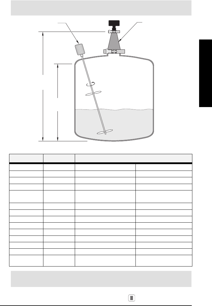
Mounting: Sanitary Mounting
There are two common sanitary mounting options; the 2”, 3”, and 4” tri-clamp with rod
antenna and the sanitary 4” horn antenna.
Wetted Parts:
W
etted Parts:Wetted Parts:
W
etted Parts:
PTFE or UHMW-PE only.
If the horn diameter is too large for the standpipe
opening, you need to insert it from inside the vessel.
The horn must be connected to the IQ 300 process
flange.

Page 32 IQ Radar 300 PL-611
Installation
Installation
Installation
Installation
Mounting: Location
Due to the polarization effect of the
microwave signal related to the
wall of the vessel, we recommend
locating the IQ 300 a minimum of
30cm (1’) away from the sidewall
for every 3m (10’) of vessel height.
Polarization Effect
Mounting the unit too close to a wall may cause echoes to disappear at specific levels
due to wave cancellation. A strong false reflection from an internal tank obstruction can
be reduced or eliminated by rotating the unit to reduce this polarization effect.
False Reflections
Flat obstructions and struts perpendicular to the emission cone cause large false
reflections. They reflect the radar signal with high amplitude. Round profile interfering
surfaces diffuse reflections of the radar signals and cause false reflections with low
amplitude.
20°
Keep the 20° emission cone free of
obstructions.
(rod antenna and 150mm [6”] horn antenna)
PL-611 IQ Radar 300 Page 33
Interconnection
Interconnection
Interconnection
Interconnection
Interconnection
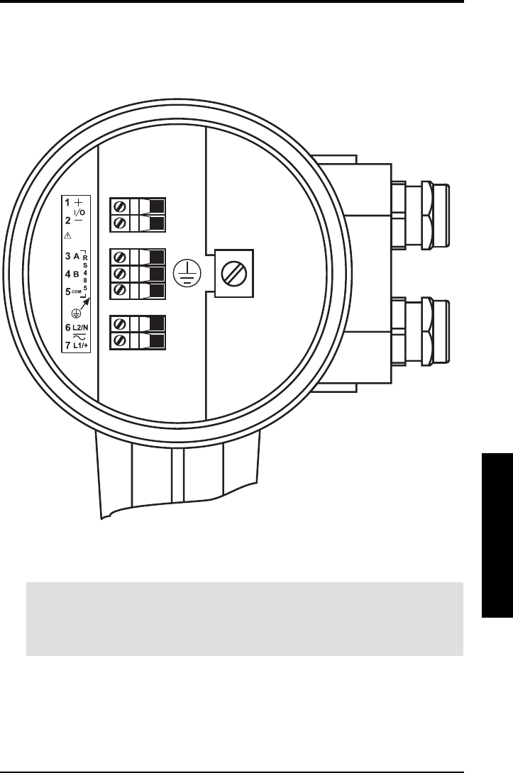
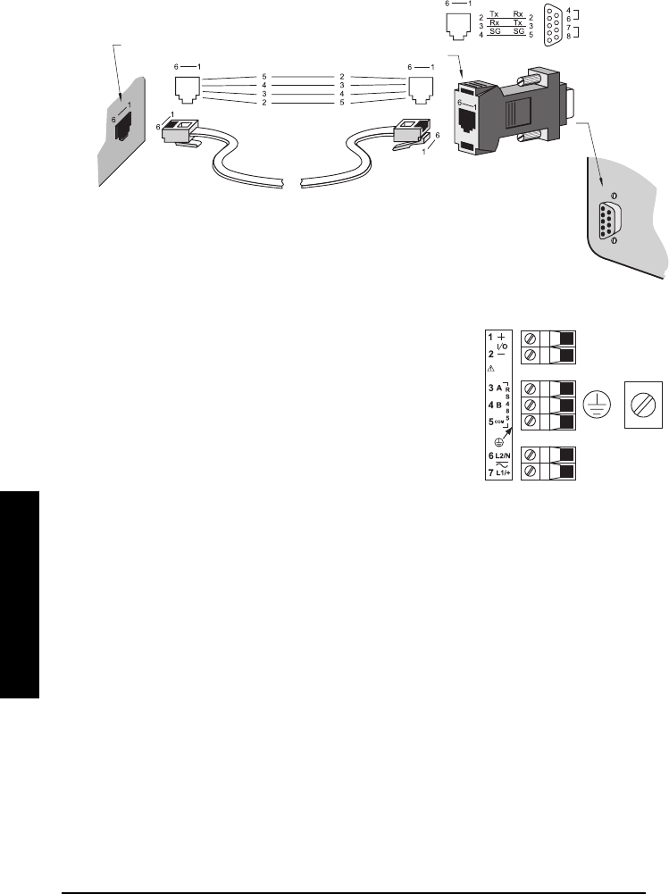
IQ Radar 300 Terminal Block
Notes
• mA, RS-485, wiring, 14 – 20 AWG, shielded copper wire
• Recommended torque on terminal clamping screws, 0.5 – 0.6 Nm
• Ground shields at one end only
Page 34 IQ Radar 300 PL-611
Interconnection
Interconnection
Interconnection
Interconnection
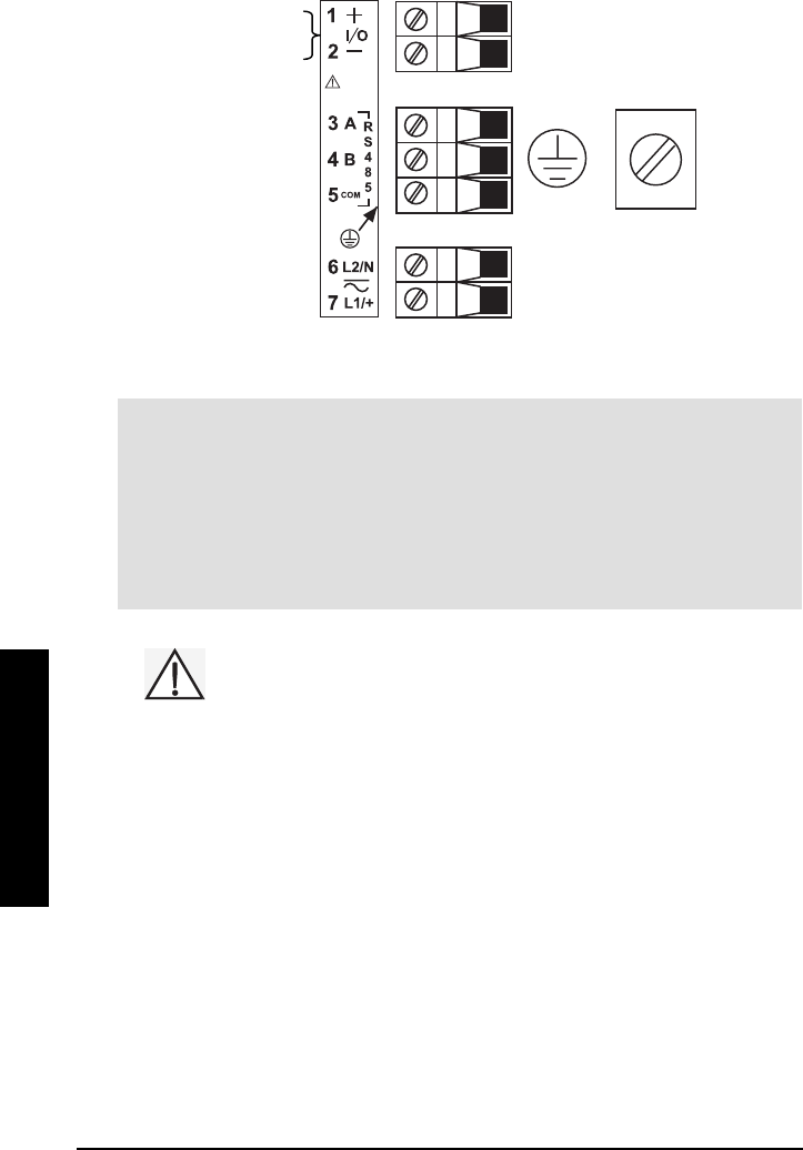
IQ Radar 300 Wiring
Notes
• Line, 12 – 14 AWG, copper wire
• The equipment must be protected by a 15 A fuse or circuit breaker in the building
installation.
• A circuit breaker or switch in the building installation, marked as the disconnect
switch, shall be in close proximity to the equipment and within easy reach of the
operator.
All field wiring must have insulation suitable for at least 250 V.
HART mA Ou
t
or
Profibus P.A.
RS-485
ground
power
supply
PL-611 IQ Radar 300 Page 35
Interconnection
Interconnection
Interconnection
Interconnection
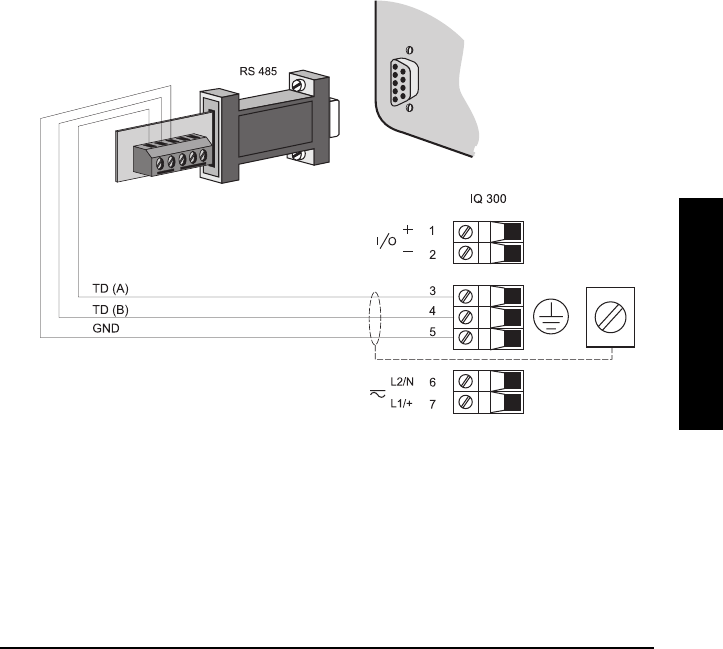
Communications Installation
Wiring Guidelines
• RS-485 maximum length is 1,220 meters (4,000 feet)
• use 24 AWG (minimum)
• use good quality communication grade (shielded twisted pairs) cable for port 1that is
recommended for RS-485.
• run the communication cable separately from power and control cables. (Do not tie
wrap your RS-485 cable to the power cable or have them in the same conduit.)
• use shielded cable and connect to ground at one end only
• follow proper grounding guidelines for all devices on the bus
Improper wiring and incorrect cable choices are the two most common causes of
communication problems.
Port 1: RS-485
The terminal block uses terminal 3,4,5 and Ground for RS-485.
Page 36 IQ Radar 300 PL-611
Interconnection
Interconnection
Interconnection
Interconnection
PC Connection
To connect the device to a computer requires the use of a RS-485 to RS-232 converter.
Milltronics offers a converter that is powered by the RS-232 port on the computer (part
number 20150159).
Port Configuration
The IQ 300 uses Modbus to establish communication parameters. See Communication
Parameters on page 72.
PL-611 IQ Radar 300 Page 37
Start Up
Start Up
Start Up
Start Up
Start Up
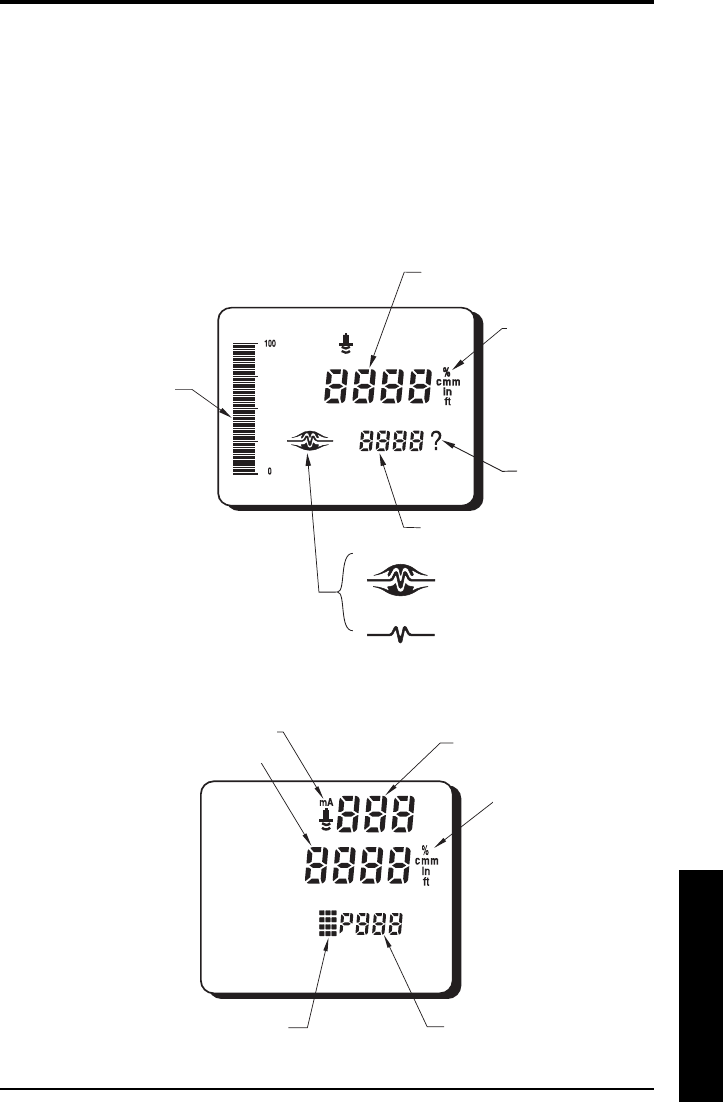
Overview
The IQ Radar 300 has two modes of operation: RUN
RUNRUN
RUN and PROGRAM
PROGRAMPROGRAM
PROGRAM. After powering up
and installation procedures are completed, the unit starts in the RUN
RUNRUN
RUN mode and detects
the distance from the antenna flange to the target in meters.
Run Mode Display
Program Mode Display
bar graph representation
of material level, 0 to 100%
of span
reading questionable,
appears during fail-safe
operation
= normal reading
= fail-safe operation
confidence icons
auxiliary reading
units
reading
parameter type
(measurement of mA output)
parameter value
units
parameter number
programming indicator
index value
Page 38 IQ Radar 300 PL-611
Start Up
Start Up
Start Up
Start Up
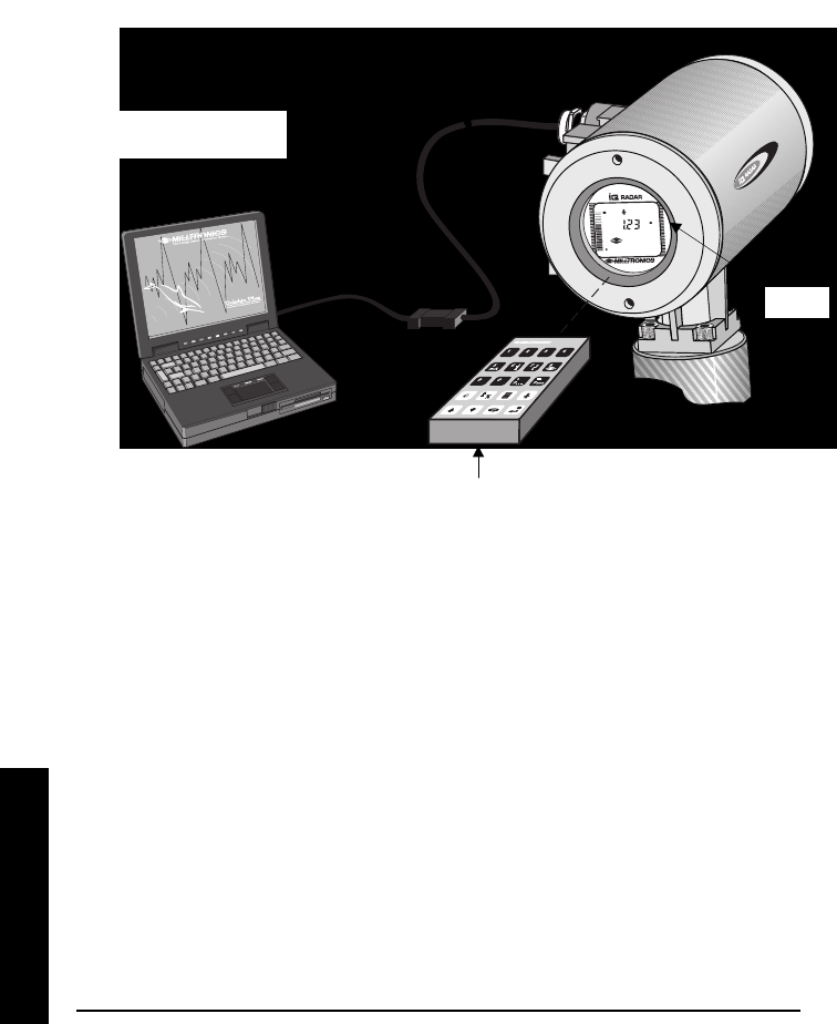
Programming
You can activate the PROGRAM
PROGRAMPROGRAM
PROGRAM mode at any time and set parameters to suit the
application and/or user preferences. Programming can be carried out locally using the
hand programmer or remotely through the optional Dolphin Plus/RS-485 interface. The
system responds to both types of programming.
The instruction examples in this manual use icons from the hand programmer.
Dolphin Plus
Dolphin Plus is a user interface program designed to configure the IQ Radar 300 from a
laptop or a desktop PC. With Dolphin Plus you can modify parameter values in real time,
view process values in graphic form on screen, save profiles, and generate instrument
configuration reports. Dolphin Plus software is purchased separately. Please contact
your Milltronics representative.
Hand Programmer
The programmer is a sturdy, hand-held, programming unit offering immediate access to
the configuration parameters. Point programmer at the IQ Radar 300 display window
(maximum distance 15cm [6”]) and press the buttons in the required sequence.
display
hand programmer
Dolphin Plus programming
interface

PL-611 IQ Radar 300 Page 39
Start Up
Start Up
Start Up
Start Up
Local Programming
The hand programmer is used for local programming sequences. Please make sure you
point the programmer directly at the unit to activate the programming options.
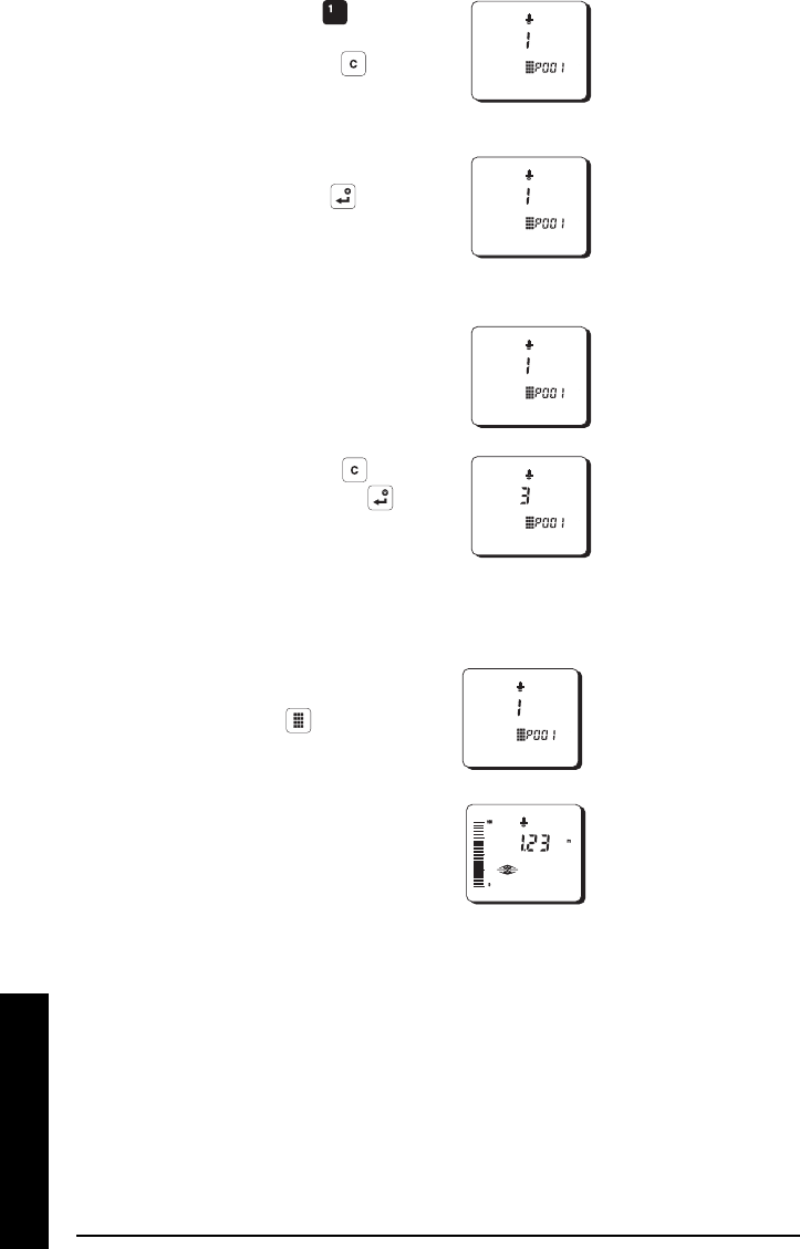
Key Programming Mode Run Mode
to Values
mA output value
Decimal point parameter for auxiliary
readings*
Negative value
Clear value
Toggle between Units and %
on reading display
End program session and enable
RUN
RUNRUN
RUN mode
Initiate and complete
program mode access
Distance
Parameter scroll-up
Parameter scroll-down
Toggle fields
Enter the displayed value
* Pressing plus three-digit parameter number, sets parameter to show in the
auxiliary display.
Numeric and
Auxiliary keys
Function Keys
Page 40 IQ Radar 300 PL-611
Start Up
Start Up
Start Up
Start Up
Accessi
iiing Program Mode
Note
NoteNote
Note: Values shown are for demonstration purposes only.
1. The unit starts in RUN
RUNRUN
RUN
mode and readings
correspond to existing
settings.
2. Press the PROGRAM
PROGRAMPROGRAM
PROGRAM key
to activate the
PROGRAM
PROGRAMPROGRAM
PROGRAM mode. Initial
program starts at P001.
Accessing a Parameter
The parameter settings configure the units to a specific use. There are two ways to
access parameter after you have pressed the PROGRAM
PROGRAMPROGRAM
PROGRAM key: Scroll Access and Direct
Address.
Scroll Access
In PROGRAM
PROGRAMPROGRAM
PROGRAM mode, you can scroll through the parameters sequentially, and in either
direction until you reach the required parameter. [scrolling range??]
1. Press ARROW
ARROWARROW
ARROW keys
to scroll up or
down.
Direct Access
In PROGRAM
PROGRAMPROGRAM
PROGRAM mode, you can access a parameter directly by entering its number.
PL-611 IQ Radar 300 Page 41
Start Up
Start Up
Start Up
Start Up
1. Press the TOGGLE
TOGGLETOGGLE
TOGGLE key
to open Parameter Number
field.
2. The Parameter Number field
goes blank.
3. Enter parameter number.
Example: . The
parameter value appears.
Note: Enter parameter numbers below 100 directly without leading zeros. Press the
ENTER key to access the parameter. Example: To access P005, press .
Modifying a Parameter Value
Once a parameter is accessed, you can set or modify its values.
Note:
• Security must be disabled. To disable security, set P000 to 1954.
• Values shown are for demonstration purposes only.
• Invalid entries will be rejected or limited.
Changing Parameter Values
1. Select parameter to modify.
2. Enter new value.
Example: press and the
ENTER key
Clearing a Parameter Value
1. Scroll to, or select, the
parameter.
value entry field
value
Page 42 IQ Radar 300 PL-611
Start Up
Start Up
Start Up
Start Up
2. Enter new value by pressing
the number key, e.g. . To
erase value or incorrect entry,
press the CANCEL key , to
clear the value and then re-
enter correct value.
3. Press the ENTER key to set
the value.
Resetting a Parameter Value
1. Scroll to or select the
parameter.
2. Press the CANCEL key and
then press the ENTER key .
The value returns to factory
default.
Accessing Run Mode
1. In PROGRAM mode, press the
PROGRAM key . The screen
may go blank for a moment
2. The IQ 300 returns to RUN
mode.
Quick Start Programming
The first step in programming is to configure all parameters to their factory settings by
performing a master reset through Parameter 999 (see page 80).
Then set these key parameters (P001 to P007) for a Quick Start:
• (P001) mode of measurement • (P005) units
• (P002) process material • (P006) empty distance
• (P003) measurement response • (P007) span
• (P004) antenna configuration

PL-611 IQ Radar 300 Page 43
Start Up
Start Up
Start Up
Start Up
Note: After these start-up parameters are configured, set Parameter P837.
Numerous other program parameters can be changed subsequently, or during another
programming session. Refer to the Parameter Descriptions section that starts on page
55 for a list of available parameters.
When programming has been completed, the IQ Radar 300 can be put into RUN by
pressing the programming button or by exiting Dolphin Plus.

Page 44 IQ Radar 300 PL-611
Start Up
Start Up
Start Up
Start Up

PL-611 IQ Radar 300 Page 45
Operation
Operation
Operation
Operation
Operation
Overview
The IQ Radar 300 is a level measuring device for liquids and slurries. Using advanced
pulse radar technology, the device calculates material level by emitting a series of radar
pulses and then analyzing their reflections.
The device consists of an enclosed electronic component mounted to a flanged antenna
component. The electronic component generates a 5.8 GHz (U.S.A. 6.3 GHz) radar signal
that is directed to the antenna, waveguide, or horn.
The radar signal is emitted axially from the antenna and propagates along this axis in a
defined conical beam decreasing in strength at a rate proportional to the square of the
change in distance.
The radar pulse detects the interface between the dielectric constant of the atmosphere
and that of the material being measured. Electro-magnetic wave propagation is not
sensitive to the temperature and atmospheric conditions or to variations in the vessel.
The series of echoes from the pulses transmitted are sensed by the antenna during the
receive period of the electronics and are then stored as a profile of the activity in the
vessel. The profile is analyzed and the distance of the material surface to the radar
antenna is determined. This distance is used as a basis for display of material level and
mA output.
Transceiver
The IQ Radar 300 transceiver operates under 1 of 5 sets of pre-set conditions (P003):
parameter
value
measurement
response
P700/P701
rate
update
time
P705
rate
update
distance
P706
echo
verification
P711
fuzz
filter
P710
fail
safe
timer
P070
1 0.1 m/min slow 600 0.30 2 100 100
2 1 m/min 300 0.10 2 50 10
3 10 m/min 60 0.05 2 10 1
4 100 m/min 60 0.05 0 1 0.1
5 1000 m/min fast 60 0.05 0 0 0
When the echoes are received, the relevant echo extraction technique (P820 and P830)
is applied to determine the true material echo.
The measurement response limits the maximum rate at which the display and analog
output respond to changes in measurement. Select this carefully, especially where liquid
surfaces are in agitation or fall into the radar path during filling.
Page 46 IQ Radar 300 PL-611
Operation
Operation
Operation
Operation
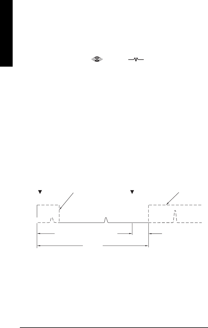
Loss of Echo (LOE)
A loss of echo occurs when the IQ 300 deems the calculated measurement unreliable,
i.e. the confidence (P805) is less than the threshold (P804). Refer to Operation
Troubleshooting on page 91
If the condition persists for a time beyond the limit as set by the fail-safe timer (P070), the
Confidence icon changes from full to partial:
to
The response to LOE is set by P072. It determines whether the reading and mA output
are immediately forced to the fail-safe default (P071). Upon receiving a reliable echo, the
loss of echo condition is aborted (icon returns to full), and the reading and mA output
return to the present level at the rate set by P072.
Blanking
Near blanking (P800) is set to ignore the zone in front of the antenna where false echoes
can appear as an echo during the receive cycle (often created by internal impediments
like a ladder rung). Usually indicated by an incorrect high level reading, false echoes can
be overcome by increasing the near blanking value from its factory setting.
Far-end blanking is a feature that ignores the zone below the zero or empty level where
false echoes can appear at levels that interfere with the processing of the true echo.
Typical Receiver Signal
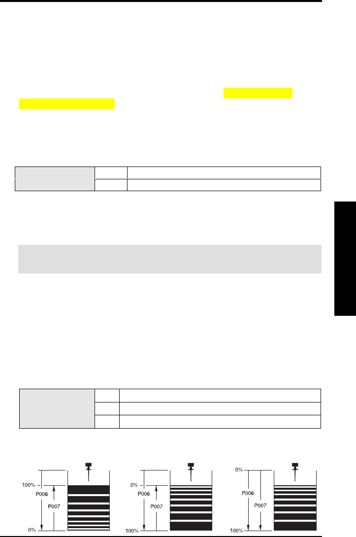
In applications where the zero level is above the bottom of the vessel and you need to
monitor the zone below the normal zero, range extension (P801) can extend the range
into far-end blanking. Range extension is entered as a percentage of P006. As range
extension reduces the protection afforded by the far-end blanking, it should be used
judiciously because excessive range extension can reduce measurement reliability and
accuracy. Range extension is factory set for 5% of P006. If false echoes appear after the
blanking zone, P801 should be increased accordingly.
0
level
end o
f
transmit
far-end blanking
range extension
(P801) as % P006
empty distance to antenna
P006
P800
near blanking
range
PL-611 IQ Radar 300 Page 47
Operation
Operation
Operation
Operation
Analog Output
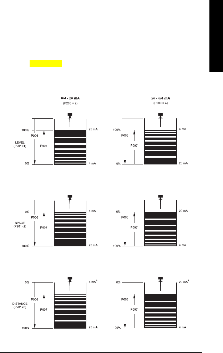
The IQ Radar 300 can be programmed to provide an analog output (P200) of 0 to 20, or 4
to 20, mA, and for proportional or inverse span.
Programming
When the unit is put into PROGRAM
PROGRAMPROGRAM
PROGRAM mode, the analog output level holds its prior value if
the mA output function is not common output or if HART is not the communication
protocol. [please verify]
Run
The analog output responds in the following manner:
*reference value only. mA level limited by near blanking.
0 and 100% are percentage of full scale reading (m, cm, mm, ft, in).

Page 48 IQ Radar 300 PL-611
Operation
Operation
Operation
Operation
Volume
To program the unit for volume, set:
• operation (P001) to level 1 (see page 55)
• tank shape (P050) to a value other than 0 (see page 57)
• other volume parameters (P051 to P053) as required.
To program the unit for ullage, set:
• operation (P001) to space 2 (see page 55).
Fail-Safe
When the fail-safe timer (P070) expires, the mA output responds as follows:
Fail-safe Mode (071) Status (0/4 - 20) Status (20 - 0/4)
1 = high 22 0/2
2 = low 0/2 22
3 = hold hold hold
Run/Program
When the IQ Radar 300 changes from RUN
RUNRUN
RUN to PROGRAM
PROGRAMPROGRAM
PROGRAM, the unit no longer responds to
the process. The last measurement is stored and the associated readings and mA
output are held.
The unit reverts to the parameter last addressed during the previous program session.
Upon return to RUN
RUNRUN
RUN, the transceiver resumes operation. The reading and mA output
default to the last measurement taken. The reading and associated outputs migrate to
the current process level at a rate controlled by the measurement response (P003).
If the IQ 300 is left in PROGRAM
PROGRAMPROGRAM
PROGRAM
mode for 10 minutes without input, it automatically
reverts to RUN
RUNRUN
RUN mode.
PL-611 IQ Radar 300 Page 49
Applications
Applications
Applications
Applications
Application Examples
These IQ Radar 300 applications examples can be used as setup references. The
parameter value tables relate the values to the functions.
Application Example: Asphalt in Storage Tank
Note: The minimum distance from the antenna face to the target is limited by the
near blanking, P800.
The application is to obtain a level
measurement and corresponding 4-20 mA
output proportional to asphalt levels in a
storage tank. The bottom of the antenna
flange is 5m from the tank bottom. The empty
level is 0m (bottom) and the full level (span) is
4.5m from the bottom. The maximum rate of
filling or emptying is about 0.1m/min. In the
event of a loss of echo, the IQ Radar 300 is to
go into fail-safe Hi after 2 minutes.
Asphalt build-up on the rod antenna does not
affect performance.
Parameter Enter
P999 ---- master reset
P001 1mode of measurement = level
P002 1material = liquid
P003 2measurement response = 1m/minute
P004 240 antenna = dielectric rod, standard
length
P005 1units = metres
P006 5empty distance = 5m
P007 4.5 span = 4.5m
P070 2fail-safe timer = 2 minutes
P071 1fail-safe = Hi
P820 1algorithm = factory
P830 4TVT type = factory
P837
(Note below) 2 & 1 Auto Near TVT = 0 (factory set)
Note: Only set P837 if product is at least 2.5m (78”) away. If closer, leave P837 at 0
00
0
until such time the level drops below 2.5m (78”).
Run: To start normal operation, press the PROGRAM key .
Empt
y
(P006)
Span
(P007)
Page 50 IQ Radar 300 PL-611
Applications
Applications
Applications
Applications
Application Example: Horizontal Tank with
Volume
Note: The minimum distance from the antenna face to the target is limited by the
near blanking, P800.
The application is to obtain a level measurement and corresponding 4-20 mA output
proportional to material levels in a chemical tank. The bottom of the antenna flange is
3.5m from the tank bottom. The empty level is 0m (bottom) and the full level (span) is
3.0m from the bottom. The maximum rate of filling or emptying is about 0.1 m/min. In the
event of a loss of echo, the IQ Radar 300 is to go into fail-safe Hi after 2 minutes.
Parameter Enter
P999 ---- master reset
P001 1mode of measurement = level
P002 1material = liquid
P003 2measurement response = 1m/minute
P004 240 antenna = dielectric rod, standard
length
P005 1units = metres
P006 5empty distance = 5m
P007 4.5 span = 4.5m
P050 7tank shape = parabolic ends
P051 8000 maximum volume = litres
P052 .8 tank dimension A = metres
P053 6tank dimension L = metres
P070 2fail-safe timer = 2 minutes
P071 1fail-safe = Hi
P820 6algorithm = first echo
P830 4TVT type = factory
P837
(Note below) 2 & 1 Auto Near TVT = 0 (factory set)
Note: Only set P837 if product is at least 2.5m (78”) away. If closer, leave P837 at 0
00
0
until such time the level drops below 2.5m (78”).
Run: To start normal operation, press the PROGRAM key .
3000mm
122.4
500mm
(20.4”)
PL-611 IQ Radar 300 Page 51
Applications
Applications
Applications
Applications
Application Example: Juice Batch Tank with
Sanitary Horn Antenna
Note: The minimum distance from the antenna face to the target is limited by the near
blanking, P800.
Parameter Enter
P999 ---- master reset
P001 1mode of measurement = level
P002 1material = liquid
P003 2measurement response = 1m/min.
P004 240 antenna = dielectric rod,
standard length
P005 1units = metres
P006 5empty distance = 5m
P007 4.5 span = 4.5m
P070 2fail-safe timer = 2 minutes
P071 1fail-safe = Hi
P652 tag value offset correction = factory
P820 1algorithm = factory
P830 4TVT type = factory
P837
(Note below)
2 & 1 Auto Near TVT = 0 (factory set)
Note: Only set P837 if product is at least 2.5m (78”) away. If closer, leave P837 at 0
00
0
until such time the level drops below 2.5m (78”).
Run: To start normal operation, press the PROGRAM key .
P006
P007
existing 4” tri-clamp connection
mixer
mixer
4” sanitary horn
Note: Sanitary Antenna Options: The one-piece antenna/process seal provides excellent mounting method, even on non-
sanitar
y
installations.
Page 52 IQ Radar 300 PL-611
Applications
Applications
Applications
Applications
Application Example: Sliding Waveguide on
Anaerobic Digesters
Blanking, P800, and offset P652 are set at the factory. Check the device tag for specific
values.
Maximum level should be maintained at
least .46m (18”) from the end of the horn.
The raised position is for installation and
maintenance. The lowered position is for
operation. Program the unit for operation in
the lowered position.
Parameter Enter
P999 ---- master reset
P001 1mode of measurement = level
P002 1material = liquid
P003 2measurement response = 1m/minute
P004 240 antenna = dielectric rod, standard
length
P005 1units = metres
P006 5empty distance = 5m
P007 4.5 span = 4.5m
P652 tag value offset correction = factory
P800 tag value blanking = factory
P820 1algorithm = factory
P830 4TVT type = factory
P837
(Note below) 2 & 1 Auto Near TVT = 0 (factory set)
Note: Only set P837 if product is at least 2.5m (78”) away. If closer, leave P837 at 0
00
0
until such time the level drops below 2.5m (78”).
Run: To start normal operation, press the PROGRAM key .
P006
P007
horn
PL-611 IQ Radar 300 Page 53
Applications
Applications
Applications
Applications
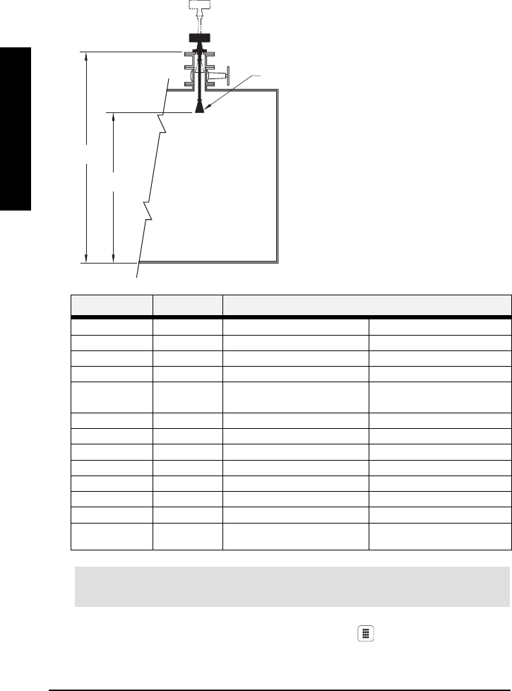
Application Example: Stillpipe
An alternate to the waveguide antenna, this option is also used for products with an εr or
less than 3 or if extremely turbulent or vortex conditions exist.
Note: For εr < 3, the lower 40cm of vessel level may not be measurable.
This mounting arrangement can also be used to provide optimum signal conditions on
foaming materials.
Suitable pipe diameters are 50mm (2”) to 250mm (10”).
Note: The measurement range is reduced to 13m (43’) for a 50mm (2”) stillpipe or
14.5m (47’) for an 80mm (3”) stillpipe.
Parameter Enter
P999 ---- master reset
P001 1mode of measurement = level
P002 1material = liquid
P003 2measurement response = 1m/minute
P004 240 antenna = dielectric rod, standard
length
P005 1units = metres
P006 5empty distance = 5m
P007 4.5 span = 4.5m
P655 (see
chart below)
0.955 propagation factor = 10mm (4”) pipe
P820 6algorithm = factory
P830 4TVT type = factory
P837
(Note below) 2 & 1 Auto Near TVT = 0 (factory set)
vent hole
100mm (4”) diameter

Page 54 IQ Radar 300 PL-611
Applications
Applications
Applications
Applications
Note: Only set P837 if product is at least 2.5m (78”) away. If closer, leave P837 at 0
00
0
until such time the level drops below 2.5m (78”).
Pipe P655 Value
50mm (2”) 0.827
80mm (3”) 0.915
100mm (4”) 0.955
150mm (6”) 0.980
200mm (8”) 0.990
Note:
See the P655 table on page 67 for other pipe diameters.
Run: To start normal operation, press the PROGRAM key .
PL-611 IQ Radar 300 Page 55
Parameters
Parameters
Parameters
Parameters
Parameter Descriptions
The parameters are the programmable features of the IQ Radar 300. Adjust the value
settings on the parameters to configure the unit.
The parameter tables show the values you need to enter in bold type, followed by
additional information when necessary. The pre-set values are the unit’s factory settings
that may need alteration for specific applications.
Press the PROGRAM key to access the parameter settings. [Tim: do you want to
indicate the default values?]
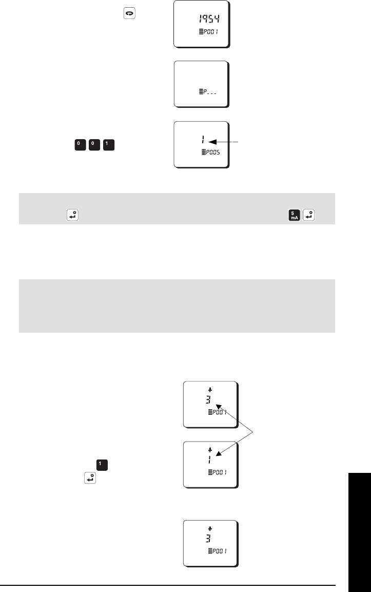
P000 Lock
Secures the IQ Radar 300 from changes.
1954 Lock off: programming permitted
Value other Lock activated: programming secured
To access this parameter directly, press 000 and enter any value other than 1954 to
secure the programming lock. The PROGRAM mode is active for viewing only. To
unlock, access this parameter and enter 1954.
WARNING: Use this lock as backup security only. It uses a fixed value which
can be discovered by unauthorized personnel.
Quick Start Parameters (P001 to P007)
Parameters P001 to P007 are the main settings that apply to all applications and get the
system operational.
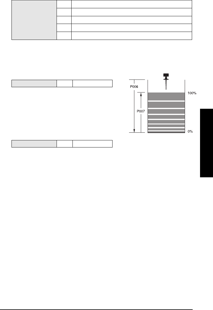
P001 Operation
Determines the mode of measurement.
1Level: material level referenced to empty distance (P006)
2Space: space to material level referenced from span (P007)
Values
3Distance: distance to target referenced from the flange face
Level (a.k.a. volume)
(P001 = 1)
Space (a.k.a ullage)
(P001 = 2)
Distance
(P001 = 3)
Page 56 IQ Radar 300 PL-611
Parameters
Parameters
Parameters
Parameters
P002 Material
Identifies the material being monitored.
Values 1 liquids or slurries
P003 Measurement Response
Sets the reaction speed of the unit to the measurement changes in the target range.
measurement
response
P700/P701
rate
update
time
P705
rate
update
distance
P706
fuzz
filter
P710
echo
verification
P711
fail
safe
timer
P070
1 0.1m/minute slow 600 secs 0.30 m 2100100
2 1m/minute 300 secs 0.10m 25010
3 10m/minute 60secs 0.05m 2101
4 102m/minute 60secs 0.05m 010.1
Values
5 1020m/minute fast 60secs 0.05m 000
Set P003 to a measurement response just faster than the greater measurement of the
maximum filling or emptying rate.
If the IQ 300 cannot keep up with the rate of level change, select a faster rate. If the
reading bounces around an average value, select a slower rate. In general, reliability is
traded for speed. Noisy applications or those with agitators tend to be more manageable
at slower response rates, as these make use of filtering, echo verification, and longer
fail-safe delay.
• filter:
averages successive measurements to filter out false echoes
• echo verification: discriminates between agitator blades in motion (spurious noise) and
the target surface (true echo)
• fail-safe timer: establishes the period from the time a loss of echo (LOE) starts until the
fail-safe default (P071) is triggered. The P003 pre-set timer value can be overridden by
P070.
P004 Antenna
Identifies antenna configuration. [Tim: is this final?]
240 factory
241 rod + 50mm extension
242 rod + 100mm extension
Values
243
243243
243 rod + 150mm extension (50 + 100mm)
Setting this parameter automatically configures the offset correction, P652.
Horn antennas and waveguide/horn combinations will come from the factory with P652
pre-set and P004 set to 240. [still ok?]
PL-611 IQ Radar 300 Page 57
Parameters
Parameters
Parameters
Parameters
P005 Units
Specifies units for programming and measurement.
1metres
2centimetres
3millimetres
4feet
Values
5inches
P006 Empty
Sets the distance in units (see P005) from flange face
to empty level.
Values ----- # units set in P005
Empty level can be set at any distance
desired, not just actual empty.
P007 Span
Sets the distance from empty (P006) to full/100% level.
Values ----- # units set in P005
Full level can be set at any measurement
above the empty level.
Volume Parameters (P050 to P053)
Sets the IQ Radar 300 to calculate readings based on reservoir volume, rather than level
P050 Tank Shape
Enter the Tank Shape value that matches the monitored vessel or reservoir.
When Operation is LEVEL
LEVELLEVEL
LEVEL (P001 = 1), liquid (material) volume is calculated. When
operation is SPACE
SPACESPACE
SPACE, remaining vessel capacity is calculated.
In the RUN
RUNRUN
RUN
mode, Readings are displayed in volumetric units, see Maximum Volume
(P051) on page 59. When percent is selected, the displayed volume Reading is a
percentage of Maximum Volume.
Note: Parameters P052 and P053 set tank dimensions A and L.
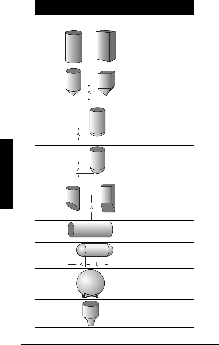
Page 58 IQ Radar 300 PL-611
Parameters
Parameters
Parameters
Parameters
Value
ValueValue
Value
#
##
#
Shape
ShapeShape
Shape Description
DescriptionDescription
Description
0---- volume calculation not
required (Factory disabled)
1flat bottom
2conical or pyramidal bottom
3parabolic bottom
4spherical bottom
5angled bottom
6flat ends
7parabolic ends
8sphere
9universal linear

PL-611 IQ Radar 300 Page 59
Parameters
Parameters
Parameters
Parameters
P051 Max Volume
For Readings in volumetric units (rather than percent), enter the vessel volume between
Empty (P006) and Span (P007).
Values Range:
0.000 to 9999
Related Parameters • P006 Empty
• P007 Span
The units of measurement for this reading are non-dimensional. The volume is
calculated from the empty position to the maximum position and is scaled according to
the Tank Shape (P050) value. This allows the use of any volume units required.
Example
1. If maximum volume = 3650m3, enter 3650
36503650
3650.
2. If maximum volume = 267500 gallons, enter 267.5
267.5267.5
267.5 (1000s of gallons).
Enter the volume of the tank at full (Factory Setting = 100)
P052 Tank Dimension A
Dimension A is used in the tank shape parameter (P050) on page 57.
Values Range: 0.000 to 9999
0.000 to 9999 0.000 to 9999
0.000 to 9999 in units (P005)
)))
Related Parameters • P050 Tank Shape
If P050 = 2,3,4, or 5, enter the height of the tank bottom.
If P050 = 7, enter the length of one end section of the tank.
Note: Enter the dimension in units chosen in (P005).
P053 Tank Dimension L
Dimension L is used in the tank shape parameter (P050) on page 57.
Values Range:
: :
: 0.000 to 9999
in units (P005)
Related Parameters • P050 Tank Shape
If P050 = 7, enter the tank length (excluding both end sections).
Note: Enter the dimension in units chosen in (P005).
Page 60 IQ Radar 300 PL-611
Parameters
Parameters
Parameters
Parameters
P054 Breakpoint Levels
When the tank shape is too complex for any of the pre-configured shapes, you can
specify the volume based on segment.
Primary Index global
Secondary Index breakpoint
Values Range:
0.000 to 9999
in units
Related Parameters • P055 Volume Breakpoints (Universal Volume Calculation)
Enter up to 10 level breakpoints (where volume is known) if P050 = 9 [verify]
Entering a Level Breakpoint
1. Open parameter P054.
2. Enter a breakpoint in measurement units.
3. Match each breakpoint to the same index value for P055.
P055 Volume Breakpoints (Universal Volume Calculation)
Each segment defined by the level breakpoints (P055) requires a volume to allow the IQ
300 to make the level-to-volume calculations.
Primary Index global
Secondary Index breakpoint
Range:
0.
...000 to
to to
to 9999
in units
Values Pre-set: 0.000
Related Parameters • P054 Volume Breakpoints (Universal Volume Calculation)
Typical volume calculations:
Cone Cylinder
V = (1/3)πr2hV = πr2h
Entering a Volume Breakpoint
1. Open parameter P055
2. For each index enter a volume
3. Match each volume to the same index value for P054

PL-611 IQ Radar 300 Page 61
Parameters
Parameters
Parameters
Parameters
Display and Reading Parameters (P060 to P063)
P060 Decimal Position
Defines the maximum number of decimal places used on the LCD.
0no digits after the decimal point
11 digit after the decimal point
22 digits after the decimal point
Values (Level
measurement only)
33 digits after the decimal point
In the RUN
RUNRUN
RUN mode, the decimal position is adjusted to prevent the number of digits from
exceeding the display capabilities. To keep the decimal place from shifting, reduce the
number of decimal places to that shown at 100%.
For example, if 100% = 15m, use two decimal places for readings of 15.00 or parts
thereof (e.g. 12.25).
P062 Offset Reading
Adds the specified value to the level reading, usually to reference the reading to sea
level or to another datum level.
Range:
-999 to 9999
Values (
Values (Values (
Values (Level
measurement only)
measurement only)measurement only)
measurement only) Pre-set: 0.000
The operation of the device is not affected by the Offset Reading. This value is used for
display only. All control measurements are still referenced to empty.
P063 Minimum Reading
Adjusts the minimum reading the product will show.
Range:
-999 to 9999
Values (
Values (Values (
Values (Level
measurement only)
measurement only)measurement only)
measurement only) Pre-set: 0.000
P063 is only applied after P062 Offset Reading and then only if reading displays
level/volume (P001=1).
The milliAmp output is not affected.

Page 62 IQ Radar 300 PL-611
Parameters
Parameters
Parameters
Parameters
Fail-Safe Parameters (P070 to P072)
P070 Fail-Safe Timer
Sets the time delay, in minutes, before going into fail-safe mode.
Range:
: :
: 0.000 to 9999
Values
Pre-set: 10.00 minutes
P071 Fail-Safe Material Level
Selects the default measurement in the event that the fail-safe timer expires.
1High: maximum span value
2Low: minimum span value
Values
3Hold: hold current value
P072 Fail-Safe Level Advance
Sets the speed at which the IQ 300 advances and returns to the Failsafe Material Level.
1Restricted (pre-set): unit advances to/from the Failsafe Material lev
e
as set by P003, P700, or P701.
2Immediate: Failsafe Material Level is assumed at once.Values
3Fast Back: Failsafe Level Advance is restricted. Returns to new
measured material level at once.
mA Parameters (P200 to P219)
P200 mA Range
Selects the mA output range and relationship to span.
24 to 20mA
Values 420 to 4mA
If 2 is selected, the mA output is directly proportional to the mA function. If 4 is selected,
then the output is inversely proportional to the mA function.

PL-611 IQ Radar 300 Page 63
Parameters
Parameters
Parameters
Parameters
P201 mA Function
Alters the mA output/measurement relationship. Set independently from P001.
0manual
1level
2space
3distance
4volume
Values
9controlled by HART or Modbus
Independent mA Setpoints Parameters (P210 and P211)
Use these features as reference for calculating the minimum and/or maximum mA
output to any point in the measurement range.
Note: Ensure the % symbol is displayed before entering a % value.
P201 (mA Function) Settings Response
level, space, or distance Enter the material level in Units (P005) or percent of Span
(P007) as referenced to Empty (P006).
volume Enter the volume in Maximum Volume (P051) units or as a
percent of Maximum Volume.
P210 0/4mA Output Setpoint
Sets the process level that corresponds to the 0 or 4mA value.
Values Range: -999 to 9999
Related
Parameters • P200 mA Range
• P201 mA Function
Enter the value (in units or %) to correspond to 0 or 4mA.
P211 20mA Setpoint
Sets the process level that corresponds to the 20mA value.
Values Range: -999 to 9999
Related Parameters • P200 mA Range
• P201 mA Function
Enter the value (in applicable units or %) to correspond to 20mA.

Page 64 IQ Radar 300 PL-611
Parameters
Parameters
Parameters
Parameters
P214 mA Trim
Used to calibrate the mA output for 4mA.
Values Range: -1.00 to 1.000
Related Parameters • P215 mA Trim
Adjust this value so the input device indicates 4.000mA when P214 is accessed. Clearing
this parameter returns unit to factory setting.
P215 mA Trim
Used to calibrate the output for 20 mA.
Values Range: -1.00 to 1.000
Related Parameters • P214 mA Trim
Adjust this value so the device indicates 20.00mA when P215 is accessed. Clearing this
parameter returns unit to factory setting.
P219 mA Output Fail-Safe
Use for mA fail-safe operation, independent of the Fail-Safe Material Level (P071).
0 Off (pre-set) mA output responds to Failsafe Material Level
1 HI produce the Span mA output immediately
2 LO produce the Empty mA output immediately
Values
3HOLd last known value is held until normal operation
resumes
Profile Record Parameters (P330 to P337)
WARNING: These parameters are for authorized service personnel or
Technicians familiar with Milltronics echo processing techniques.
These features can record up to 10 Echo profiles, initiated manually (P330), or
automatically (P331). See Scope displays (P810) for echo profile viewing
hardware/software requirements. If 10 Profiles are already saved, addresses 1 through
10 are filled, and the oldest automatically initiated record is overwritten. Manually
initiated records are not automatically overwritten. All records are automatically deleted
in the event of a power interruption.
When a record is displayed, results are based on current programming (which may have
been altered since the record was saved), so the effect on the echo profile can be
observed when changing an echo parameter.
PL-611 IQ Radar 300 Page 65
Parameters
Parameters
Parameters
Parameters
P330 Profile Record.
Records profiles for later viewing.
In addition to being a profile records library, this provides two functions:
• manually records and saves echo profiles
• displays an echo profile, recorded manually or automatically, (oscilloscope)
Selecting a record address
1. Enter PROGRAM mode and press TOGGLE key twice to highlight the index field. The
field shows two underscores _ _
_ __ _
_ _.
2. Type the index number. The profile record information is shown.
3. Use ARROW keys and to scroll through the records.
Recording a profile manually
Press the TRANSDUCER key to fire the transducer and record the echo profile into
the internal scope buffer for display.
Saving a manual record
Press the ENTER key to copy the echo profile record in the scope buffer and save it
in the selected address in the record library. The parameter value field displays the new
record information.
Displaying a record
Press the AUXILIARY key to enter display auxiliary mode and then:
1. Press to display the time the profile was taken.
2. Press to display the date the profile was taken.
3. Press the TRANSDUCER key to copy the current echo profile into the scope buffer
for display on an oscilloscope or in Dolphin Plus.
To delete a record
Press the CANCEL key and then the ENTER key to delete the echo profile
record in the selected address. The value returns to - - - -
- - - -- - - -
- - - -.
P331 Auto Record Enable
Enables or disables the Auto Profile Record function.
0Off
Values 1On
P333 Auto Record Interval
Sets the allowable time lapse (in minutes) after an Auto Profile Record is saved before
another Auto Profile Record can be saved (subject to all other restrictions).

Page 66 IQ Radar 300 PL-611
Parameters
Parameters
Parameters
Parameters
Range:
0.0 to 9999
(minutes)
Values Pre-set: 120 minutes
Auto Record ON and OFF Setpoint Parameters (P334 to
P337)
Use Auto Record ON Setpoint (P334) and Auto Record OFF Setpoint (P335) to define the
level boundaries that trigger an Auto Profile Record of an Echo Profile.
If ---- is displayed for either P334 or P335, Auto Profile Records are saved, regardless of
current level (subject to all other restrictions).
Enter the level value in Units (P005) or percent of Span (P007) relative to Empty (P006).
P334 Auto Record ON Setpoint
Sets the critical level which, along with Auto Record OFF
OFFOFF
OFF Setpoint, defines the
boundaries for Auto Profile Records to be saved.
Values Range:
-999 to 9999
Related Parameters
• P335 Auto Record OFF
• P336 Auto Record Filling/Emptying
• P337 Auto Record LOE Time
P335 Auto Record OFF Setpoint
Sets the critical level which, along with Auto Record ON
ONON
ON Setpoint, defines the
boundaries for Auto Profile Records to be saved.
Values Range:
-999 to 9999
Related Parameters
• P334 Auto Record ON
• P336 Auto Record Filling/Emptying
• P337 Auto Record LOE Time
P336 Auto Record Filling/Emptying
Restricts Auto Profile Records from being saved unless the level is rising, falling, or both.
0Auto Profile Record on filling or emptying
1Auto Profile Record on filling only
Values
2Auto Profile Record on emptying only
Related Parameters
• P334 Auto Record ON
• P335 Auto Record OFF
• P337 Auto Record LOE Time
• P702 Filling Indicator
• P703 Emptying Indicator

PL-611 IQ Radar 300 Page 67
Parameters
Parameters
Parameters
Parameters
If the level changes at a greater rate than the corresponding Filling/Emptying Indicator
(P702/P703) values, the Echo Profile is saved subject to this and other Auto Profile
Record restrictions.
P337 Auto Record LOE Time
Limits Auto Profile Records from being saved unless extended LOE occurs.
Range: 0.0 to 9999
(seconds)
Values Pre-set: 0.0
Related Parameters • P334 Auto Record ON
• P335 Auto Record OFF
• P336 Auto Record Filling/Emptying
If the LOE condition exceeds the period entered the Echo Profile is saved. When set for 0
0 0
0
(zero) LOE is not required for an Auto Profile Record to be saved.
Installation Records Parameter
P341 Run Time
Shows the accumulated number of days the IQ Radar 300 has been operating.
Values (view only) Display:
0.0 to 9999 (days)
Range Calibration Parameters
P652 Offset Correction
Shows the offset value applied to the reading as a correction to the measurement.
Range:
-999 to 9999
Values Pre-set: 0
Note: This parameter is automatically set when you enter parameter P004. This parameter may
also have been factory set to a specific value to accommodate options such as horn and
waveguide antenna systems. A tag on the instrument will specify the P652 value when these
options have been supplied.
P655 Propagation Factor
Compensates for the change in the microwave velocity, as compared with propagation
in free space, when propagation is within a stillpipe (metal).
Range:
0.000 to 1.000
Values Pre-set: 1
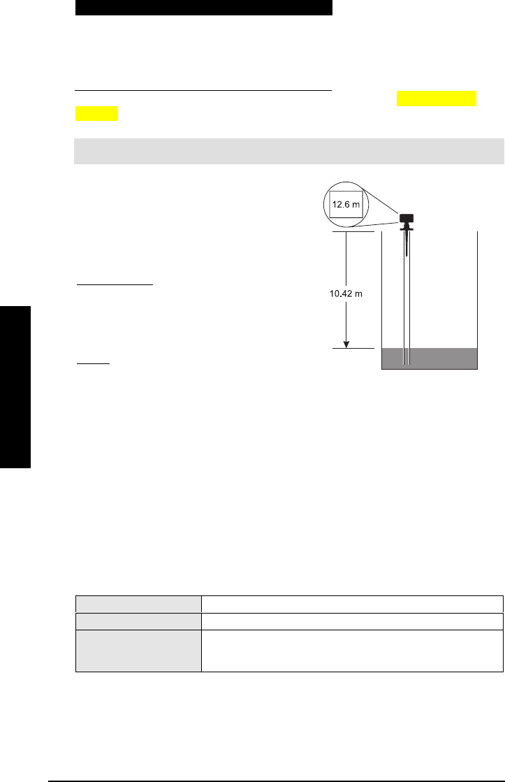
Page 68 IQ Radar 300 PL-611
Parameters
Parameters
Parameters
Parameters
Pipe Size (i.d.) Propagation Factor
50mm (2”)0.827
80mm (3”)0.915
100mm (4”)0.955
150mm (6”)0.980
20 mm (8”)0.990
Consult the factory for other sizes and propagation factor numbers.[Tim: who at the
factory?]
Note:
: :
: For waveguide antennas used as stillpipes, this value is on the product tag.
The propagation factor is constant for a given
pipe diameter, or can be determined by
comparing the radar distance reading to the
actual process material distance (measured
from the face of the IQ 300 flange).
actual distance = p.f.
IQ 300 distance
Using the readings shown:
10.42m = 0.827
12.6m
Enter the propagation factor: 0.827
0.8270.827
0.827
Rate Parameters
These parameters determine how material level changes are reported.
P700 Maximum Fill Rate
Adjusts the IQ 300 response to increases in the actual material level (or an advance to a
higher Failsafe Material Level, P071).
Values
ValuesValues
Values Range: 0.000 to 9999 (stored in meters)
Altered by
Altered byAltered by
Altered by • P003 Measurement Response
Related Parameters
Related ParametersRelated Parameters
Related Parameters
• P005 Units
• P007 Span
• P071 Fail-Safe Material Level
Enter a value slightly greater than the maximum vessel filling rate. This value, in Units
(P005) or % of Span (P007) per minute, is automatically altered when Maximum Process
Speed (P003) is altered.
PL-611 IQ Radar 300 Page 69
Parameters
Parameters
Parameters
Parameters
P003 Value Meters/Minute
10.1
21
310
4 100
5 1000
P701 Maximum Empty Rate
Adjusts the IQ 300 response to decreases in the actual material level (or an advance to a
lower Failsafe Material Level, P071).
Values
ValuesValues
Values Range: 0.000 to 9999 (stored in meters)
Altered by
Altered byAltered by
Altered by • P003 Measurement Response
Related Parameters
Related ParametersRelated Parameters
Related Parameters
• P005 Units
• P007 Span
• P071 Fail-Safe Material Level
Enter a value slightly greater than the vessel’s maximum emptying rate. This value, in
Units (P005) or % of Span (P007) per minute, is automatically altered when Measurement
Response Speed (P003) is altered. Any emptying rate above this value will trigger any
alarms set to Rate.
P003 Value Meters/Minute
10.1
21
310
4 100
5 1000
P704 Rate Filter
Damps Rate Value (P707) fluctuations.
0rate display not required
1continuously filtered and updated
Values
2update rate (use P705/P706)
Alters • P707 Rate Value
Related Parameters • P705 Rate Update Time
• P706 Rate Update Distance
Enter the time or distance interval over which the Rate Value is to be calculated before
the display updates.
This is automatically altered along with Measurement Response Speed (P003).

Page 70 IQ Radar 300 PL-611
Parameters
Parameters
Parameters
Parameters
P705 Rate Update Time
Sets the time period (in seconds) over which the material level rate of change is
averaged before Rate Value update.
Values Range: 0.000 to 9999
Related Parameter • P707 Rate Value
P706 Rate Update Distance
The material level change (in metres) to initiate a Rate Value update.
Values Range: 0.000 to 9999
Related Parameter • P707 Rate Value
P707 Rate Value
The rate of material level change (in Units (P005) or % of Span (P007) per minute).
Values (view only) Display: -999 to 9999
Altered By • P704 Rate Filler
Related Parameters • P005 Units
• P007 Span
A negative rate indicates the vessel is emptying.
Measurement Verification Parameters
P710 Fuzz Filter
Stabilizes the reported level due to level fluctuations (such as a rippling or splashing
liquid surface) within the Echo Lock Window (P713).
Values Range: 0 to 100 (0= off)
Altered by • P003 Measurement Response
Related Parameters • P007 Span
• P713 Echo Lock Window
This value (in % of Span, P007) is automatically altered when Measurement Response
Speed (P003) changes. The higher the value entered, the greater the range of stabilized
fluctuation.

PL-611 IQ Radar 300 Page 71
Parameters
Parameters
Parameters
Parameters
P711 Echo Lock
Selects the measurement verification process.
0off
1maximum verification
2material agitator
Values
3total lock
Related Parameters
• P700 Maximum Fill Rate
• P701 Maximum Empty Rate
• P712 Echo Lock Sampling
• P713 Echo Lock Window
• P820 Algorithm
If a material agitator (mixer) is used in the vessel monitored, set Echo Lock to 1
11
1
(maximum verification) or 2
22
2 (material agitator) to avoid agitator blade detection. To avoid
stationary blade detection, ensure the agitator is always ON while the IQ 300 is
monitoring the vessel.
When set for 1 (maximum verification) or 2 (material agitator), a new measurement
outside of the Echo Lock Window (P713) must meet the sampling criterion (P712).
For 3 (total lock), Echo Lock Window (P713) is pre-set to 0
(zero). The IQ 300 continuously
searches for the best echo according to the algorithm chosen (P820). If the selected
echo is within the window, the window is then centered about the echo. If not, the
window widens with each successive shot until the selected echo is within the window.
The window then returns to its normal width.
When Echo Lock is 0 (off) the IQ 300 responds immediately to a new measurement, as
restricted by the Max Fill/Empty Rate (P700/P701). However, measurement reliability is
affected.
P712 Echo Lock Sampling
Sets the number of consecutive echoes appearing above or below the echo currently
locked onto. Sampling ratio must occur before the measurements are validated as the
new reading (for Echo Lock P711 values: 1 or 2).
Range: 1:1 to 99:99
Values Format: x:y
• x = the number of above echoes
• y = the number of below echoes
Related Parameter • P711 Echo Lock
P711 value P712 pre-set value
1: max verification 5:5
2: material agitator 5:2

Page 72 IQ Radar 300 PL-611
Parameters
Parameters
Parameters
Parameters
Example Settings:
• P711 = 2: material agitator
• P712 = 5:2
Results:
• A new reading will not be validated unless 5 consecutive measurements higher or
2 consecutive measurements lower than the current reading occurs.
Note: Resetting P711 returns P712 to the respective pre-set values.
P713 Echo Lock Window
Adjusts the new measurement changes permitted before the Echo Lock is applied.
Range: 0.000 to 9999
Values Pre-set: 0.000
Altered by • P003 Maximum Process Speed
Related Parameters • P005 Units
• P711 Echo Lock
The Echo Lock Window is a “distance window” (Units, P005) centered on the echo and
used to derive the Reading. When a new measurement is in the window, it is re-
centered and the new Reading calculated. Otherwise, the new measurement is verified
by Echo Lock (P711) before the reading is updated.
When 0 is entered, the window is automatically calculated after each measurement. For
slower values, the window is narrow; for faster P003 values, the window is wider.
Communication Parameters
The IQ 300 uses Modbus to establish communication parameters. To set the IQ 300 to
either local programming or remote programming, go to P799. The Modbus Register
Map is on.
P770 Serial Protocol
Sets the communications protocol used on the RS-485 port.
0Communications disabled
1Internal use only
2Modbus ASCII slave serial protocol
Values
3Modbus RTU slave serial protocol
P771 Protocol Address
Allocates the unique identifier of the IQ 300 on the network for the RS-485 port.
Range: 0 to 9999
Values Pre-set: 1
PL-611 IQ Radar 300 Page 73
Parameters
Parameters
Parameters
Parameters
For devices connected with a serial Modbus slave protocol, this parameter is a number
from 1-247. The network administrator must ensure that all devices on the network have
unique addresses. Do not use the value 0
00
0 (zero) for Modbus communications because
this is the broadcast address and is inappropriate for a slave device.
P772 Baud Rate
Sets the communication rate with the master device.
4.8 4800 baud
9.6 9600 baud
19.2 19,200 baud
Values
38.4 38,400 baud
This specifies the rate of communication in Kbaud. Any value may be entered, but only
the values shown are supported. The baud rate should reflect the speed of the
connected hardware and protocol used.
P773 Parity
Sets the serial port parity for the RS-485 port.
0No Parity (default)
1Odd Parity
Values
2Even Parity
Note: Ensure that the communications parameters are identical between the IQ
Radar 300 and all connected devices.
Data Bits and Stop Bits
There are eight data bits and one stop bit.
P799 Communications Control
This parameter determines the read/write access to parameters via remote
communications. If it has a value of 0, then the user can only read parameters. If it has a
value of 1, then the user can read and write parameters. If it has a value of 2, then the
user can read/write P799, but can only read other parameters.
0Read only
1Read/write
Values
2Restricted access – read only except for P799 which is read/writ
e

Page 74 IQ Radar 300 PL-611
Parameters
Parameters
Parameters
Parameters
Note: P000 and P799 are exclusive, but locks can be implemented in different ways.
• HART lock device command sets P000 to a locked value and sets P799 to 2
• The hand programmer retains control if P000 is set to UNLOCK.
Echo Processing Parameters
P800 Near Blanking
Sets the amount of blanking as measured from the flange face and extending into the
measurement range. See Blanking on page 46.
Range: 0 to 9999
Values Pre-set: 0.4m
Enter value in units of P005.
Note:
::: This parameter may be set at the factory. If so, the appropriate values appear
on the product tag.
P801 Range Extension
Sets the amount of range extension as measured from the empty distance (P006) and
extending into the far-end blanking. See Blanking on page 46.
Range: 0 to 99%
Values Pre-set: 5%
Enter value as a % of P006. The distance below empty is not blanked.
For tanks with conical or parabolic bottoms, increase this parameter to ensure that an
empty tank reads empty.
P804 Confidence Threshold
Sets the minimum echo confidence in dB that the echo must meet in order to prevent a
loss of echo condition and the expiration of the fail-safe timer (P070).
Range: 0 to 99
Values Pre-set: 5
Related Parameters • P070 Fail-Safe Timer
P805 Echo Confidence
Measures echo reliability.
Values (view only) Display: 0 to 99

PL-611 IQ Radar 300 Page 75
Parameters
Parameters
Parameters
Parameters
Related Parameters • P804 Confidence Threshold
P806 Echo Strength
Displays the strength of the selected echo, in dB above 1 µV rms.
Values (view only) Display: 0 to 9
P807 Noise
Displays the average and peak ambient noise (in dB above 1 µV RMS) being processed.
x = average (-9 to 99)
Values (view only) y = peak (-9 to 99)
The noise level is a combination of transient noise and electrical noise (receiving
circuitry).
Algorithm Parameters
P820 Algorithm
Selects the algorithm to be applied to the echo profile in order to extract the true echo.
[verify chart]
1ALF = flat A
AA
Area, L
LL
Largest, and F
FF
First average
2A = flat A
AA
Area only
3L = flat L
LL
Largest only
4F= flat F
FF
First only
5AL = flat A
AA
Area and L
LL
Largest average
6AF = flat A
AA
Area and F
FF
First average
7LF = flat L
LL
Largest and F
FF
First average
8bLF = smooth L
LL
Largest or F
FF
First
9bL = smooth L
LL
Largest only
Values
10 bF = smooth F
FF
First only
Select 1 for most applications and all mounting locations except the center of the vessel.
Select 6 for the center of the vessel mounting location and for still pipes and waveguide
antennas used as stillpipes.
Page 76 IQ Radar 300 PL-611
Parameters
Parameters
Parameters
Parameters
TVT Adjustment Parameters
The following parameters are for authorized Milltronics Service personnel or
Technicians familiar with Milltronics echo processing techniques.
P830 TVT Type
Selects the TVT Curve used.
1reserved
2reserved
3reserved
4Smooth 2 (Factory Set)
5reserved
Values
6reserved
Related Parameters • P835 TVT Slope Min
Select the TVT type which gives the highest confidence (P805) under all level conditions.
Use this parameter with caution, and do not use TVT Slopes with the bF or bLF
Algorithm (P820).
P831 TVT Shaper
Turns the TVT Shaper ON
ONON
ON or OFF
OFFOFF
OFF.
0
00
0off
Values 1
11
1on
Related Parameters • P832 TVT Shaper Adjust
Turn the TVT Shaper ON before using P832, and afterwards turn the TVT Shaper ON and
OFF while monitoring the effect to pick up the true echo.
P832 TVT Shaper Adjust
Allows manual adjustment of the TVT curve.
Range: -50 to 50
Values Pre-set: 0
Related Parameters • P831 TVT Shaper
Use this feature to bias the shape of the TVT curve to avoid crossing false echoes from
fixed objects.
Adjustment to this parameter is best done while viewing the echo profile with Dolphin
Plus. Refer to the Dolphin Plus online help for details. The TVT curve is divided into 40
breakpoints, accessible by enabling the point number as the breakpoint index field. Each
breakpoint is normalized to a value of 0, as displayed in the parameter value field. By
changing the breakpoint value, up or down, the intensity of the bias applied to that
breakpoint of the curve is respectively changed. By changing the value of adjacent
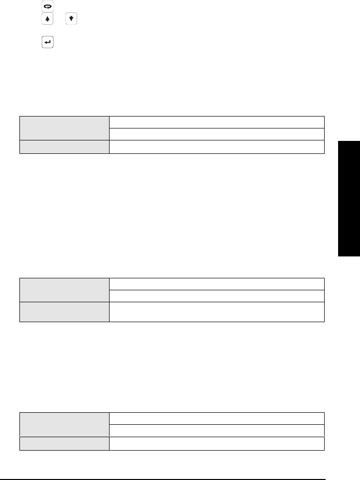
PL-611 IQ Radar 300 Page 77
Parameters
Parameters
Parameters
Parameters
breakpoints, the effective bias to the shaper can be broadened to suit the desired
correction. In the case of multiple false echoes, shaping can be applied along different
points of the curve. Shaping should be applied sparingly in order to avoid missing the
true echo.
To change a breakpoint:
1. Confirm that P831, TVT shaper, is ON.
2. Go to P832
3. Press twice to highlight the index value
4. Press or to scroll through the 40 points (or type in the desired point)
5. Enter the value from –50 to 50
6. Press
P833 TVT Start Min
Use this feature to adjust the TVT Curve height to ignore false echoes (or pick up true
echoes) near the start of the Echo Profile.
Range: 30 to 225
Values Pre-set: 50
Related Parameters • P834 TVT Start Duration
Enter the minimum TVT Curve start point (in dB above 1 uV RMS).
This feature should only be used if increased Near Blanking (P800) would extend farther
than desired into the measurement range.
P834 TVT Start Duration
Use this feature in conjunction with TVT Start Min (P833) to ignore false echoes (or pick
up true echoes) near the start of the Echo Profile.
Range: 0 to 9999
Values Pre-set: 30
Related Parameters • P833 TVT Start Min
• P835 TVT Slope Min 77
Enter the time (in ms) for the TVT Curve to decrease from the TVT Start Min (P833) point
to the TVT Curve baseline.
P835 TVT Slope Min
Enter the minimum slope (in dB/s) for the middle of the TVT Curve.
Range: 0 to 9999
Values Pre-set: 200
Related • P834 TVT Start Duration
Page 78 IQ Radar 300 PL-611
Parameters
Parameters
Parameters
Parameters
Use this feature to adjust the slope declination, and use it in conjunction with TVT Start
Duration (when a long flat TVT Type is selected) to ensure the TVT Curve remains above
the false echoes in the middle of the Echo Profile. Alternatively, if TVT Type is set for TVT
TVTTVT
TVT
Slopes
SlopesSlopes
Slopes (P830 = 6), pre-set is 2000.
P837 Auto Near TVT
Use this feature to adjust the TVT Curve height to ignore false echoes near the start of
the Echo Profile by placing the TVT above the current signal from 0m to 2m (78”).
If the IQ 300 displays a full level, or if the reading fluctuates between a high level and a
correct level, set this parameter to elevate the TVT in this region and to de-sensitize the
receiver from any ‘base noise’ caused by internal antenna reflections and/or standpipe
echoes.
Entry:
0 = Off (not used)
1 = Use Learned TVT
2 = Learn
Set Up:
1. Make sure material is at least 2.5m (78”) away.
2. Press the PROGRAM key , press the TOGGLE
key , and then select P833.
3. Press ‘2’ and then press the ENTER key .
4. Press ‘1’ and then press the ENTER key .
Press the PROGRAM key to return to RUN mode.
Test Parameters
P900 Software Revision
Displays the EPROM software revision level.
Values (view only) Range: 00.00 to 99.99
P901 Memory
Tests the memory. Test is initiated by scrolling to the parameter or repeated by pressing
the ENTER key .
PASS normal
Values (view only) FAIL consult Milltronics

PL-611 IQ Radar 300 Page 79
Parameters
Parameters
Parameters
Parameters
P904 Keypad
Press each keypad key in the following sequence:
As each key is pressed, the associated keypad number is displayed. On successful test
completion, the display reads PASS
PASSPASS
PASS. The display reads FAIL if a key is pressed out of
sequence or the programmer keypad malfunctions.
P911 mA Output Value
Displays the current value of the mA output in MilliAmps.
Values Range: 0.00 to 20.00
When P201 is set to 0 (manual), a test value can be entered and the displayed value is
transmitted to the output. Upon returning to the run mode, this value will remain. For all
other mA output functions, this parameter is read only.
P920 Reading Measurement
Displays the reading measurement that the unit is programmed for in RUN mode (P001,
operation).
Values (view only) units showing Level/Space/Distance
P921 Material Measurement
Displays the reading measurement as though the unit were programmed to read Level
(P001 = 1).
P922 Space Measurement
Displays the reading measurement as though the unit were programmed to read Space
(P001 = 2).
P923 Distance Measurement
Displays the reading measurement as though the unit were programmed to read
Distance (P001 = 3).
P924 Volume Measurement
The calculated vessel capacity in Max Volume (P051) or % of Max Volume.
Page 80 IQ Radar 300 PL-611
Parameters
Parameters
Parameters
Parameters
Values Range: 0.000 to 9999
Related Parameters • P051 Maximum volume
P999 Master Reset
Resets parameters to their factory setting.
1. Press the PROGRAM
key to activate the
PROGRAM mode.
2. Enter 999.
3. Press the CANCEL key
and then the
ENTER key to Clear
All and initiate reset.
4. Reset complete. Note:
reset takes several
seconds to complete.

PL-611 IQ Radar 300 Page 81
Communications
Communications
Communications
Communications
Communications: Modbus Register Map
The memory map of the IQ-300 occupies the Modbus holding registers (R40,001 and up).
A description of the types of data is on the following pages. The table legend is at the
bottom of the table. This map is used when protocol is Modbus RTU slave or Modbus
ASCII slave. The table legend is located at the end of the table.
Register Map for Most Common Data
Legend
Type The type of data held in the group of registers.
Start The first register to hold the referenced data.
Data Type The possible values of the data in the register. See Data Types on page 85 for
more information.
Description The type of data held in the individual registers.
#R The number of registers used for the referenced data.
Read/Write Indicates whether the register is readable, writeable, or both.
Type Description Start #R 8Data Type Read/
Write
ID Milltronics Product Code 40,064 1 3 R
Single Parameter Access (SPA) R40,090 7 see appendix III
Reading (1) 41,010 1 -20,000 to 20,000 R
Point
Data Volume (1) 41,020 1 -20,000 to 20,000 R
I/O
Data mA Output 41,110 1 0000 to 20,000 R/W
Parameter Access 43,997 to 44,999 R/W
The IQ Radar 300 was designed to make it easy for master devices to get useful
information via Modbus. This chart gives an overview of the different sections. A more
detailed explanation of each section follows below.
Product ID (R40,064)
This value identifies the Milltronics device type. For the IQ Radar 300, the value is 3.
Point Data (R41,010 – R41,031)
Measurement point data contains the current reading on the instrument. This is the
same as shown on the device’s LCD for reading, and volume for the measurement point.
The reading is based on the unit’s operation, and could be level, distance, or volume.
See the IQ 300 Parameter Descriptions on page 55 for details.
8 Maximum registers shown, fewer may be used depending on options installed.

Page 82 IQ Radar 300 PL-611
Communications
Communications
Communications
Communications
The measurement registers is 41,010.
The available register
Data Registers Parameter
Reading 41,010 P920
Volume 41,020 P924
Temperature 41,030 and 41,031 P912
The reading is expressed as a percentage of full scale, multiplied by 100:
Reading Value
0 0.00%
5000 50.00%
7564 75.64%
20,000 200.00%
Input/Output (R41,070 – R41,143)
The IQ 300 has one mA output.
mA Output (R41,110)
The mA output is scaled from 0 to 2,000 (0 to 20mA multiplied by 100). Displayed in P911.
Parameter Access (R43,997 – R46,999)
Parameter values are given as integers in the range of registers from R44,000 to R44,999.
The last three numbers of the register correspond to the parameter number.
Parameter Register # Format Register # Parameter #
44,000 46,000 P000
44,001 46,001 P001
44,002 46002 P002
………
44,999 46,999 P999
The parameters are usually all read/write.
Note:
• Parameters P000 and P999 are read only. If P000 is set to LOCK ON then all of
the parameters are read only.
• Parameter P999 (Master Reset) cannot be used via Modbus.
• See Data Types on page 85 for a description of the different types of data
associated with different parameters.
However, before a parameter can be read or written to, the format (where decimal place
is) and the indexes must be defined.

PL-611 IQ Radar 300 Page 83
Communications
Communications
Communications
Communications
Format Word (R43,997)
Format word is an unsigned integer that contains a value that represents a certain
decimal offset.
The decimal offset indicates how the remote system must interpret the integer value
that is stored in the parameter access register. The following table shows how different
parameter values can be shown based on a register value (integer) of 1234.
Decimal Offset Example
0 0 1,234
1-1 12,340
2 -2 123,400
3-3 1,234,000
4 -4 12,340,000
5-5 123,400,000
6 +1 123.4
7+2 12.34
8 +3 1.234
9Percent 12.34%
Examples of using the format word for both the index values and the decimal offset
value are shown below:
Format Decimal
00
3 3 right
8 3 left
9percent
Primary Index (P43,999) and Secondary Index
(P43,998)
Many parameters are indexed. There are two possible indexes, a primary index and a
secondary index. If there is not an index, enter a value of 1
11
1.
Reading Parameters
To read parameter values, follow the steps listed in either the Global or the Parameter
Specific Index Method that follow. You must be able to program your HMI or SCADA
system before completing these methods.
1. Write the primary index value into R43,999.

Page 84 IQ Radar 300 PL-611
Communications
Communications
Communications
Communications
This is a value between 0 and 40 which specifies the input or output indexed by the
parameter.
Examples (P920, primary index 1)
2. Write the secondary index value into R43,998.
This is a value between 0 and 40 that specifies the secondary index on the parameter.
This value is usually 0.
3. Write the desired format value into R43,997 [such as??].
4. Read the value from the appropriate parameter register.
Types of values are:
• Numeric Values on page 85.
• Split Values on page 85.
• Text Messages on page 86.
A value of 22,222 indicates that an error has occurred. Specify a different format type
and try again.
Writing Parameters
The method of writing parameters is similar to the method of reading them. Become
familiar with Reading Parameters, page 83, before attempting to write any parameters.
Writing parameter values to the IQ 300:
1. Write the primary index value into R43,999.
2. Write the secondary index value into R43,998.
3. Write the desired format value into R43,997.
4. Write the value to the appropriate parameter register.

PL-611 IQ Radar 300 Page 85
Communications
Communications
Communications
Communications
Communications: Data Types
The IQ Radar 300 parameters do not always use integers to hold values. For the
convenience of the programmer, those values are converted to and from a 16-bit integer
number. This section describes the conversion process.
Numeric Values
Numeric parameter values are the most common. For example, parameter P920
(Reading) returns a number that represents the current reading (either level or volume,
depending on the IQ-300 configuration).
Numeric values are requested or set in units or percent of span, and may be specified
using a number of decimal places.
Numeric values must be in the range -20,000 to +20,000 to be valid. If a parameter is
requested and its value is more than +20,000, the number 32,767 is returned; if it is less
than -20,000, the number -32,768 is returned. If this overflow happens, decrease the
number of decimal places.
If a parameter cannot be expressed in terms of percent of span, or has no meaningful
value, the number 22,222 is returned. Try requesting the parameter in units, or refer to
the Parameter Description section on page 55 for an explanation of the format and use
of the requested parameter.
Split Values
Certain parameters are actually a pair of numbers separated by a colon, using this
format: xx:yy.
One example is P807 (Transducer Noise) where:
xx = the average noise value in dB.
yy = the peak noise in dB.
The number which corresponds to xx:yy, for either reading or setting a parameter,
is determined by the following formula:
For storing to the device:
value = (xx + 128) x 256 + (yy + 128)
For reading from the device:
xx = (value / 256) – 128
yy = (value % 256) – 128
Where:
% is the modulus operator.
The modulus can be computed by following these steps:

Page 86 IQ Radar 300 PL-611
Communications
Communications
Communications
Communications
value1 = value / 256
value2 = remainder of value1
value3 = value2 x 256
yy = value3 – 128
It may simplify Parameter to notice:
xx = (most significant byte of value) – 128
yy = (least significant byte of value) – 128
Text Messages
If a device parameter returns a text message, that message is converted to an integer
and is then provided in the register. The numbers are shown in the following table:
Number Text Message as displayed on LCD
22222 Invalid value
30000 Off
30001 On
30002 ≡ ≡ ≡ ≡
30003 (parameter does not exist)
30004 Err
30005 Err1
30006 Open
30007 Short
30008 Pass
30009 Fail
30010 Hold
30011 Lo
30012 Hi
30013 De
30014 En
30015 (parameter has not been set)
-32768 Value is less than -20,000
32767 Value is greater than 20,000

PL-611 IQ Radar 300 Page 87
Communications
Communications
Communications
Communications
Error Handling
Modbus Responses
When polled by a Modbus Master, a slave device will do one of the following:
1. Not reply. Which means that something went wrong with the transmission of the
message.
2. Echo back the command with the correct response (see the Modbus specification for
more details). This is the normal response.
3. Return an Exception Code. This reflects an error in the message.
IQ Radar 300 uses the following exception codes:
Code Name Meaning
01 Illegal Function The function code received in the query is not
an allowable action for the slave.
02 Illegal Data Address The data address received in the query is not
an allowable address for the slave.
03 Illegal Data Value A value contained in the query data field is not
an allowable value for the slave.
Error Handling
Errors can be traced to two general sources:
5. There is an error in transmission.
or
oror
or
6. The host tries to do something that is not a valid action.
In the first case, the IQ 300 does not respond and the master waits for a Response Time
Out error, which causes the master to re-send the message.
In the second case, it depends on what the host tries to do. In general, IQ 300 will not
give an error to the host request. Various actions and the expected outcome are as
follows:
• the host reads an invalid register, the host will get an undetermined value back.

Page 88 IQ Radar 300 PL-611
Communications
Communications
Communications
Communications
• If the host writes an invalid register (a non-existing parameter or a read only
parameter), the value will be ignored and no error response will be made.
However, the current value will not reflect the desired new value.
• If the host writes a read only register, then the value will be ignored and no error
response will be made. However, the current value will not reflect the desired new
value.
• If P000 is activated, then the value will be ignored and no error response will be
made. However, the current value will not reflect the desired new value.
• If the host attempts to write one or more registers that are out of range, an
exception response code 2 or 3 is generated depending if the start address is valid.
• If the host attempts to read one or more registers that are out of range, an
exception response code of 2 or 3 is generated.
• If the host used an unsupported function code, an exception response code of 01
should be generated. However, this is not guaranteed and there may be no
response.

PL-611 IQ Radar 300 Page 89
Communications
Communications
Communications
Communications
Troubleshooting
Communication Troubleshooting
Generally
1. Check the following:
• There is power at the unit
• The LCD shows the relevant data
• The device can be programmed using the hand programmer
2. Check the wiring pin outs and verify that the connection is correct.
3. Verify that values in set-up parameters P770 to P773 match the settings in the computer
communicating with the unit.
4. Check that the port you are using on the computer is correct. Sometimes trying a
different Modbus driver will solve the problem. An easy stand-alone driver called
ModScan32 is available from Win-Tech at www.win-tech.com. We have found that this
driver is useful to test communications.
Specifically
1. You try to set an IQ 300 parameter via remote communications, but the parameter
remains unchanged.
• Some parameters can only be changed when the device is not scanning. Try
putting the device in program mode using the operating mode function.
• Try setting the parameter from the keypad. If it can not be set using the keypad,
check the lock parameter and set it to 1954.
• The communications control parameter P799 must be set to 1 to be able to write
parameter to the IQ 300.

Page 90 IQ Radar 300 PL-611
Communications
Communications
Communications
Communications

PL-611 IQ Radar 300 Page 91
Troubleshooting
Troubleshooting
Troubleshooting
Troubleshooting
Operation Troubleshooting
Operating symptoms, probable causes, and resolutions.
Symptom Cause Action
display reads level or target is out of range • check specifications
• check parameters
display reads material build-up on antenna • clean
• re-locate IQ 300
display reads location or aiming:
• poor installation
• flange not level
• standpipe not vertical
• check to ensure standpipe is
vertical
display reads antenna malfunction:
• temperature too high
• physical damage
• excessive foam
• inspect
• use foam deflector or stilling
well
• relocate
• use a defoamer
Reading does not
change, but the
level does
IQ 300 processing wrong
echo, i.e. vessel wall, or
structural member
• re-locate IQ 300
• check standpipe for internal
burrs or welds
• increase blanking, P800
Measurement is
consistently off by a
constant amount
P006 not correct
P652 not correct
• Check distance from Flange
face to zero level (P006)
• Check offset value (P652) or
device tag
Screen blank power error • check nameplate rating
against voltage supply
• check power wiring or source
echo confidence weak • refer to P805
• use foam deflector or stilling
well
liquid surface vortexed • decrease measurement
response P003
• increase confidence
threshold P804
Reading erratic
material filling • re-locate IQ 300
Reading response
slow
P003 setting • increase response if possible

Page 92 IQ Radar 300 PL-611
Troubleshooting
Troubleshooting
Troubleshooting
Troubleshooting
Symptom Cause Action
Reads correctly but
occasionally reads
high when vessel is
not full
• detecting close range echo
• build up near top of tank or
nozzle
• water or other high εr
material in antenna threads
• wrong antenna choice for
application
• stand pipe problem
• increase blanking
• increase confidence
threshold P804
• rod extensions may be
required
• See Application Example:
Stillpipe on page 53
• material is within near
blanking zone
• tank near empty and low εr
material
• multiple echoes processed
• decrease blanking P800 (min.
0.4 m)
• raise IQ 300
• decrease range extension
• install still pipe deflector
(contact Milltronics)
• set P820 to ‘6’
• Standpipe too narrow for
length
• See Rod Extension
Requirements on page 26
Level reading lower
than material level
• Internal seam in standpipe • Inspect and remove seam
Maintenance
The IQ Radar 300 requires no maintenance or cleaning under normal operating
conditions.
Note: Under severe operating conditions, the antenna may require periodic cleaning.

PL-611 IQ Radar 300 Page 93
Appendix I
Appendix I
Appendix I
Appendix I
Appendix I
Alphabetical Parameter List
Parameter Name Parameter
Number
Page Number
Auto Near TVT 837 78
Auto Record
Filling/Emptying
336 66
Auto Record Enable 331 65
Auto Record LOE Time 337 67
Auto Record Interval 333 65
Auto Record Off Setpont 335 66
Auto Record On Setpoint 334 66
Algorithm 820 75
Antenna 004 56
Baud Rate 772 73
Breakpoint Levels P054 60
Confidence Threshold 804 74
Decimal Position 060 61
Distance Measurement 923 79
Echo Confidence 805 74
Echo Lock 711 71
Echo Lock Sampling 712 71
Echo Lock Window 713 72
Echo Strength 806 75
Empty 006 57
Fail-Safe Level Advance 072 62
Fail-Safe Material Level 070 62
Fail-Safe Timer 070 60
Fuzz Filter 710 70
Keypad 904 79
Lock 000 55
mA Function 201 63
mA Output Fail-Safe 219 64
04/ mA Output Setpoint 210 63
mA Output Value 911 79
mA Range 200 62
mA Setpoint 211 63
mA Trim 214/215 64/64
Master Reset 999 80

Page 94 IQ Radar 300 PL-611
Appendix I
Appendix I
Appendix I
Appendix I
Material 002 56
Material Measurement 921 79
Maximum Empty Rate 701 69
Maximum Fill Rate 700 68
Maximum Volume 051 59
Measurement Response 003 56
Memory 901 78
Minimum Reading 063 61
Near Blanking 800 68
Offset Correction 652 67
Offset Reading 062 61
Operation 001 55
Parity 773 73
Profile Record 330 65
Propagation Factor 655 67
Protocol Address 771 72
Rate Filter 704 69
Rate Update Distance 706 70
Rate Update Time 705 70
Rate Value 707 70
Range Extension 801 68
Reading Measurement 920 79
Run Time 341 67
Serial Protocol 770 72
Software Revision 900 78
Space Measurement 922 79
Span 007 57
Tank Dimension ‘A’052 59
Tank Dimension ‘L’053 59
Tank Shape 050 57
TVT Shaper Adjust 832 76
TVT Shaper 831 76
TVT Slope Min 835 77
TVT Start Duration 834 77
TVT Start Min 833 77
TVT Type 830 76
Units 005 57
Volume Breakpoints 055 60
Volume Measurements 924 79

PL-611 IQ Radar 300 Page 95
Appendix II
Appendix II
Appendix II
Appendix II
Appendix II
Programming Chart
Number Parameter Name Value
001 Operation
002 Material
003 Measurement Response
004 Antenna
005 Units
006 Empty
007 Span
050 Tank Shape
051 Max Volume
052 Tank Dimension ‘A’
053 Tank Dimension ‘L’
054 Breakpoint Level
055 Volume Breakpoints
060 Decimal Position
062 Offset Reading
063 Minimum Reading
070 Fail-Safe Timer
071 Fail-Safe Material Level
072 Fail-Safe Level Advance
200 mA Range
201 mA Range
210 0/4mA Output Setpoint
211 20mA Setpoint
214 mA Trim
215 mA Trim
219 mA Output Fail-Safe
330 Profile Record
331 Auto Record Enable
333 Auto Record Interval
334 Auto Record ON Setpoint
335 Auto record OFF Setpoint
336 Auto Record Filling/Emptying
337 Auto Record LOE Time
341 Run Time
652 Offset Correction
655 Propagation Factor
700 Maximum Fill Rate
701 Maximum Empty Rate
704 Rate Filter
705 Rate Update Time
706 Rate Update Distance
707 Rate Value
710 Fuzz Filter
711 Echo Lock
712 Echo Lock Sampling

Page 96 IQ Radar 300 PL-611
Appendix II
Appendix II
Appendix II
Appendix II
Number Parameter Name Value
713 Echo Lock Window
770 Serial Protocol
771 Protocol Address
772 Baud Rate
773 Parity
799 Communications Control
800 Near Blanking
801 Range Extension
804 Confidence Threshold
805 Echo Confidence
806 Echo Strength
807 Noise
820 Algorithm
825 Echo Marker Trigger
830 TVT Type
835 TVT Slope Min
837 Auto Near TVT
900 Software Revision
901 Memory
904 Keypag
911 mA Output Value
920 Reading Measurement
921 Material Measurement
922 Space Measurement
923 Distance Measurement
924 Volume Measurement

PL-611 IQ Radar 300 Page 97
Appendix III
Appendix III
Appendix III
Appendix III
Appendix III
Single Parameter Access (SPA)
This appendix provides advanced communication information to qualified personnel,
enabling access to any parameter value in any available format.
Built into the IQ Radar 300 is an advanced handshaking area used to read and write
single registers to the unit. This section performs function similar to the Parameter
Descriptions section on page 55, with two qualifiers:
1. Advanced section is more powerful and harder to program.
2. Advanced section only gives you access to one parameter at a time.
Mapping
Parameter Read and Write (40,090 – 40,097) is a series of eight registers used for
reading and writing parameter values to and from the IQ 300. The first three registers
are always unsigned integers representing parameters and index values. The second
five registers are the format and value(s) of the parameter.
All parameters normally accessed through the hand-held programmer are available
through these registers.
Address Description
40,090 Parameter (integer)
40,091 Primary Index (integer)
40,092 Secondary Index (integer)
40,093 Format word (bit mapped)
40,094 Read value, word 1
40,095 Read value, word 2
40,096 Write value, word 1
40,097 Write value, word 2
Reading Parameters
Complete the following to read parameters through Modbus:
1. Send the parameter, its primary index, and its secondary index (usually 0), and
format to registers 40,090 to 40,093.
2. Wait until you can read the written values from the registers (40,090 to 40,093) to
confirm that the operation is complete.
3. Read the value from registers 40,094 and 40,095.

Page 98 IQ Radar 300 PL-611
Appendix III
Appendix III
Appendix III
Appendix III
Writing Parameters
Complete the following to set parameters through Modbus:
1. Send the parameter, its primary index, and its secondary index (usually 0) to
registers 40,090, 40,091, and 40,092.
2. Write the value to registers 40,096 and 40,097.
3. Write the desired format word to register 40,093 to enable the IQ-300 to interpret
the value correctly.
Format Register
Bits Values Description
1-8 0-2 Error Code
9-11 0-7 3-bit number representing decimal offset
12 0/1 direction of offset (0 = right, 1 = left)
13 0/1 Numeric format: Fixed (0) or Float (1)
14 0/1 Read or Write of data, Read (0), Write (1)
15 0/1 Word order: Most Significant Word first (0), Least Significant
Word first (1)
16 Reserved
For example, to format the level reading so that it is shown in percent with two decimal
places shifted left, the format bits would look like this:
Bit Numbers 16151413121110090807060504030201
Bit Values 0000001000000000
reserved
most significant first
read
fixed format
offset direction to right
decimal offset of 2
no error code
The value sent to the IQ 300 is 0000001000000000 binary or 4608 decimal. The value 4608
46084608
4608
is sent as an integer to register 40,093 to format the output words 40,094 and 40,095
accordingly.

PL-611 IQ Radar 300 Page 99
Appendix III
Appendix III
Appendix III
Appendix III
If the numeric data type is set for integer and the value contains decimal places, they
are ignored. In this situation, use the decimal offset to ensure that you have an integer
value and then write your code to recognise and handle the decimal offset.
Error Codes
The error codes returned in the format area are 8-bit integers, found in the lowest 8 bits
of the format word. This allows for 256 potential error codes.
There are currently two error codes available in the IQ 300.
Values Description
0 No error
1 Data not available as percent (available as units)
2-255 Reserved

Page 100 IQ Radar 300 PL-611
Appendix III
Appendix III
Appendix III
Appendix III
PL-611 IQ Radar 300 Page 101
Appendix IV
Appendix IV
Appendix IV
Appendix IV
Appendix IV
Temperature De-rating
Note:
Note:Note:
Note: UHMW-PE is limited to a maximum continuous service temperature of 80°C /
176°F.
Process temperature in degrees Celsius at IQ 300 flange.
ambient temperature in degrees Celsius at enclosure
e.g. If the IQ 300 is operating in an ambient temperature of 60 °C, then
the maximum process temperature allowable at the flange is 100 °C.
Page 102 IQ Radar 300 PL-611
Appendix IV
Appendix IV
Appendix IV
Appendix IV
Rod Antenna ANSI Hole Pattern, 150#9, 10
Rod Antenna DN Hole Pattern, PN169, 10
9 UHMW-PE antennas are rated to a maximum of 80°C (176°F) of continuous duty.
10 Customer to provide adequate bolting to retain vessel pressure and provide sufficient sealing.
temperature (˚C)
2”
4”
3
”
6”
pressure (bar, gauge)
temperature (˚C)
50mm
100mm
80mm
150mm
pressure (bar, gauge)
PL-611 IQ Radar 300 Page 103
Appendix IV
Appendix IV
Appendix IV
Appendix IV
Rod Antenna Threaded Connection
Rod Antenna Sanitary Connection11
11 UHMW-PE antennas are rated to a maximum of 80°C (176°F) of continuous duty; however,
they can be used for periods of up to 3 hours at temperatures up to 120°C (248°F) at 1 bar pressure.
temperature (˚C)
2”
4”
3”
pressure (bar, gauge)
temperature (˚C)
1½” and 2”
pressure (bar, gauge)
Page 104 IQ Radar 300 PL-611
Appendix IV
Appendix IV
Appendix IV
Appendix IV
Horn Antenna or Wave Guide – ANSI Hole
Pattern, 150#12
Horn Antenna or Wave Guide DN Hole Pattern,
PN1612
12 Customer to provide adequate bolting and flat-faced gasket to retain vessel pressure and
provide sufficient sealing.
temperature (˚C)
3”
6”
4”
8”
pressure (bar, gauge)
temperature (˚C)
80mm
150mm
100mm
200mm
pressure (bar, gauge)

PL-611 IQ Radar 300 Page 105
Appendix IV
Appendix IV
Appendix IV
Appendix IV
Horn Antenna Sanitary Connection
50
45.0
0
-50 100 150 200
5.0
10.0
15.0
20.0
25.0
30.0
35.0
40.0
pressure (bar, gauge)
temperature (˚C)
4” PTFE

Page 106 IQ Radar 300 PL-611
Appendix IV
Appendix IV
Appendix IV
Appendix IV

PL-611 IQ Radar 300 Page 107
Appendix V
Appendix V
BZT Approval – English
Regulierungsbehörde für Telekommunikation und Post
Regulierungsbehörde für Telekommunikation und PostRegulierungsbehörde für Telekommunikation und Post
Regulierungsbehörde für Telekommunikation und Post
Telecommunications
TelecommunicationsTelecommunications
Telecommunications
Decree 39/1998
Decree 39/1998Decree 39/1998
Decree 39/1998
General Licence No. 826 Intended for common use when employing transmission and reception plants of
General Licence No. 826 Intended for common use when employing transmission and reception plants ofGeneral Licence No. 826 Intended for common use when employing transmission and reception plants of
General Licence No. 826 Intended for common use when employing transmission and reception plants of
MILLTRONICS LIMITED company, Worcester, England.
MILLTRONICS LIMITED company, Worcester, England.MILLTRONICS LIMITED company, Worcester, England.
MILLTRONICS LIMITED company, Worcester, England.
1. Based on § 47 par. 1 and 5 of the Telecommunications Law (TKG) from July 25th, 1996 (BGBI. I.S. 1120, the
frequency 5.8 GHz is assigned as General Assignment for common use when employing transmission and
reception radio plants distributed by MILLTRONICS LIMITED company, Worcester, England, and characterized by
the designation “IQ Radar”. These radio plants are used for level measurement in chemical Industry plants with
maximum radiating capacity of 30uW and a bandwidth of up to 1.3GHz. This General Assignment does not exclude
further assignments of the same frequency for similar or equal purposes when using other devices.
2. The radio plants must be identified as follows: “Bundesadler”(Federal Eagle Symbol), assignment number “BZT
G750826K”, company name “MILLTRONICS LIMITED, Worcester, England” and identification “IQ Radar”.
3. The use of this frequency must not Interfere with other telecommunication or radio plants.
4. This General Assignment does not provide any protection for users of such radio plants against frequency
interferences by users operating in the same frequency range.
Additional Information for the distributor and users of radio plants sold under this General Assignment
Additional Information for the distributor and users of radio plants sold under this General AssignmentAdditional Information for the distributor and users of radio plants sold under this General Assignment
Additional Information for the distributor and users of radio plants sold under this General Assignment
1. There is no need for particular frequency assignment or for conformity rating as ruled by §61 of the
Telecomunications Law. If the radio plants sold for this frequency use and for this purpose comply electrically and
mechanically with a design technically proofed by an accredited testing lab and if they are identified as described
under #2 of the above mentioned regulations.
2. The identification label must be applied to the radio devices’ enclosure, either on a nameplate or in an appropriate
location on the enclosure. When stamped or engraved, it must be visible. The identification must be time and
wear resistant and must be fixed in such a way to the enclosure, in order that any attempted removal of the latter
will cause it to tear. It must always be visible from the outside.
3. The distributing company has to add a complete reprint of this General Assignment to each device for sale under
the above mentioned approval.
4. The General Assignment allows for interconnection of the radio plants with other telecommunication plants,
provided there is a need to do so. In this case, the corresponding technical requirements and legal requirements
for telecommunication must be respected. If the telecommunication plants to be interconnected with the radio
plants are linked to public telecommunication networks, the interconnection is subject to a preceding written
authorization by the Telecommunications and Mail Regulation Service. For further information, please contact the
responsible offices of this Service.
5. The above mentioned transmission and reception radio plants must comply with the EMVG directives, and
consequently include CE identification.
6. The General Assignment does not deal with the security of persons in electromagnetic fields, nor with the
electrical or mechanical security of radio plants, including antenna plants. Those are subject to special
regulations and directives.
7. The General Assignment only applies to frequency use in its legal aspect for telecommunication. It does not
involve any other directives, even if they concern legal aspects for telecommunication, and third-party rights,
particularly additional permissions and approvals, if required, with regards to construction and private jurisdiction,
for example.
Gazette 7/98

Page 108 IQ Radar 300 PL-611
Appendix
V
BZT Approval – German Original Text
Regulierungsbehörde für Telekommunikation und Post
Regulierungsbehörde für Telekommunikation und PostRegulierungsbehörde für Telekommunikation und Post
Regulierungsbehörde für Telekommunikation und Post
Fernmeldewesen
FernmeldewesenFernmeldewesen
Fernmeldewesen
Vfg 39/1998
Vfg 39/1998Vfg 39/1998
Vfg 39/1998
Allgemeinzuteilung Nr. 826 für die Benutzung durch die Allgemeinheit unter Verwendung von Sende- und
Allgemeinzuteilung Nr. 826 für die Benutzung durch die Allgemeinheit unter Verwendung von Sende- undAllgemeinzuteilung Nr. 826 für die Benutzung durch die Allgemeinheit unter Verwendung von Sende- und
Allgemeinzuteilung Nr. 826 für die Benutzung durch die Allgemeinheit unter Verwendung von Sende- und
Empfangsfunkanlange der Firma MILLTRONICS LIMITED, Worcester, England.
Empfangsfunkanlange der Firma MILLTRONICS LIMITED, Worcester, England.Empfangsfunkanlange der Firma MILLTRONICS LIMITED, Worcester, England.
Empfangsfunkanlange der Firma MILLTRONICS LIMITED, Worcester, England.
1. Hiermit wird auf Grund § 47 Abs. 1 und 5 des Telekommunikationsgesetzes (TKG) vom 25. Juli 1996 (BGBI. I S. 1120)
die Frequenz 5,8 GHz
Frequenz 5,8 GHzFrequenz 5,8 GHz
Frequenz 5,8 GHz als Allgemeinzuteilung für die Benutzung durch die Allgemeinheit unter Verwendung von
Sende- und Empfangsfunkanlagen der Vertriebsfirma MILLTRONICS LIMITED, Worcester, England
Vertriebsfirma MILLTRONICS LIMITED, Worcester, EnglandVertriebsfirma MILLTRONICS LIMITED, Worcester, England
Vertriebsfirma MILLTRONICS LIMITED, Worcester, England, mit der
Typenbezeichnung “IQ Radar
IQ RadarIQ Radar
IQ Radar” zugeteilt, Diese Funkanlagen dienen der Füllstandsmessung in Anlagen der
Füllstandsmessung in Anlagen derFüllstandsmessung in Anlagen der
Füllstandsmessung in Anlagen der
chemischen Industrie
chemischen Industriechemischen Industrie
chemischen Industrie mit einer Strahlungsleistung von maximal 30 uW und einer belegten Bandbreite von bis zu
1,3 GHz. Diese Allgemeinzuteilung schließt weitere Zuteilungen der gleichen Frequenz zu ähnlichen oder gleichen
Zwecken unter Verwendung anderer Geräte nicht aus.
2. Die Funkanlagen sind wie folgt zu kennzeichnen: Bundesadler
BundesadlerBundesadler
Bundesadler, Zulassungsnummer “BZT G750826K
BZT G750826KBZT G750826K
BZT G750826K”, sowie der
Name der Vertriebsfirma MILLTRONICS LIMITED, Worcester, England und der Typenbezeichnung “
IQ Radar
”.
3. Im Rahmen dieser Frequenznutzung dürfen andere Telekommunikationsanlagen sowie andere Funkanlagen nicht
gestört werden.
4. Im Rahmen dieser Allgemeinzuteilung besteht für die Benutzer solcher Funkanlagen keinerlei Schutz vor
frequenzmäßigen Beeinträchtigungen durch andere Frequenznutzer im gleichen Frequenzbereich.
Zusatzhinweise für die Vertriebsfirma und die Benutzer einer unter dieser Allgemeinzeteilung in den
Zusatzhinweise für die Vertriebsfirma und die Benutzer einer unter dieser Allgemeinzeteilung in denZusatzhinweise für die Vertriebsfirma und die Benutzer einer unter dieser Allgemeinzeteilung in den
Zusatzhinweise für die Vertriebsfirma und die Benutzer einer unter dieser Allgemeinzeteilung in den
Verkehr gebrachten Funkanlage
Verkehr gebrachten FunkanlageVerkehr gebrachten Funkanlage
Verkehr gebrachten Funkanlage
1. Es bedarf keiner weiteren Frequenzzuteilung und keiner Konformitätsbewertung im Sinne des § 61 TKG im
einzelnen, wenn die für diese Frequenznutzung und diesen Verwendungszweck in Verkehr gebrachten
Funkanlagen mit dem bei einem akkreditierten Prüflabor technisch geprüften Baumuster elektrisch und
mechanisch übereinstimmen und wie unter Ziffer 2 der o. a. Bestimmungen beschrieben, gekennzeichnet sind.
2.
2.2.
2. Die Kennzeichnung ist am Gehäuse der Funkanlagen, entweder auf einem Typenschild oder an örtllich
zusammenhängender Stelle, wenn die Form einer Prägung oder Gravur gewählt wird, an gut sichtbarer Stelle
anzubringen. Die Kennzeichnung muß dauerhaft und abnutzungssicher ausgeführt und so mit dem Gehäuse
Die Kennzeichnung muß dauerhaft und abnutzungssicher ausgeführt und so mit dem GehäuseDie Kennzeichnung muß dauerhaft und abnutzungssicher ausgeführt und so mit dem Gehäuse
Die Kennzeichnung muß dauerhaft und abnutzungssicher ausgeführt und so mit dem Gehäuse
verbunden sein, daß sie beim Entfernen zerstört wird. Sie muß von außen jederzeit sichtbar sein.
verbunden sein, daß sie beim Entfernen zerstört wird. Sie muß von außen jederzeit sichtbar sein.verbunden sein, daß sie beim Entfernen zerstört wird. Sie muß von außen jederzeit sichtbar sein.
verbunden sein, daß sie beim Entfernen zerstört wird. Sie muß von außen jederzeit sichtbar sein.
3. Die Vertriebsfirma dieser Funkanlagen ist verpflichtet, jedem unter dem o. g. Zulassungszeichen in den Verkehr zu
bringenden Funkgerät einen vollständigen Nachdruck dieser Allgemeinzuteilung beizufügen.
4. Auf Grund dieser allgemeinen Frequenzzuteilung düfen diese Funkanlagen mit anderen Telekommunikationsanlagen
zusammengeschaltet werden, soweit dafür ein Bedarf besteht und die jeweiligen technischen und
telekommunikationsrechtlichen Anforderungen erfüllt werden.
Sofern die Telekommunikationsanlangen, mit denen diese Funkanlagen zusammenschaltet werden sollen, mit
öffentlichen Telekommunikationszetzen verbunden sind, bedarf diese Zusammenschaltung der vorherigen
schriftlichen Genehmigung der Regulierungsbehörde für Telekommunikation und Post (Reg TP). Entspreschende
Auskünfte erteilen die zuständigen Außenstellen der Reg TP.
5. Die obengenannten Sende- und Empfangsfunkanlagen müssen die Vorschriften des EMVG erfüllen, also auch
eine CE-Kennzeichnung tragen.
6. Diese allgemeine Frequenzzuteilung hat weder die Sicherheit von Personen in elektromagnetischen Feldern noch die
elektrische und mechanische Sicherheit der Funkanlagen einschließlich der Antennenanlagen zum Gegenstand.
Hierfür gelten die einschlägigen Bestimmungen und Vorschriften.
7. Diese allgemeine Frequenzzuteilung betrifft nur telekommunikationsrechtliche Aspekte der Frequenznutzung.
Sonstige Vorschriften, auch telekommunikationsrechtlicher Art, und Rechte Dritter, insbesondere ggf. zusätzliche
erforderliche Zulassungen und Genehmigungen, z. B. baurechtlicher oder privatrechtlicher Art bleiben unberührt.
Amtsblatt 7/98

PL-xxx title Page 3
Bleed Tabs
Bleed Tabs
Bleed Tabs
Bleed Tabs
Index