Siemens Canada Siemens Milltronics Process Instruments LR400-1 RADAR LAVEL GAUGE User Manual 7ML19985FH05
Siemens Canada Ltd. - Siemens Milltronics Process Instruments RADAR LAVEL GAUGE 7ML19985FH05
UserManual.wiki
>
Siemens Canada Siemens Milltronics Process Instruments
>
LR400 1 User Manual
USERS MANUAL
Navigation menu
Upload a User Manual
Namespaces
Wiki Guide
HTML
PDF
Info
Views
User Manual
Discussion / Help
Navigation
![Page 10 SITRANS LR 400 – INSTRUCTION MANUAL 7ML19985FH04mmmmmSpecificationsApprovals (verify against device nameplate)• Explosion Protection (Liquids)Certificate No. PTB 00 ATEX 1024*Refer to device II 1/2G EEx d IIC T6II 2G EEx d IIC T6 nameplate II 1/2G EEx dem IIC T6II 2G EEx dem IIC T6II 1/2G EEx dem [ib] IIC T6II 2G EEx dem [ib] IIC T6II 1/2G EEx dem [ia] IIC T6II 2G EEx dem [ia] IIC T6FM/CSA Class I, Div. 1, Groups B, C, D; Class II/III, Div. 1, Groups E, F, G• Explosion Protection (Solids)FM/CSA Class II, Div. 1, Groups B, C,D; Class II/III, Div. 1,Groups E,F and GCertificate No. DMT 01 ATEX E 038II 1/2 D IP 65 (dust zone 20, zone 21 approval)• General CSAus/c, FM• Radio FCC, Industry Canada, European Radio• Shipping (Liquids version) Lloyd’s Register of Shipping, Categories ENV1, ENV2, ENV3, and ENV5WARNING: This product is designated as a Pressure Accessory per directive 97/23/EC and is not intended for use as a safety device.Note: Please ensure these are the most recent specifications. Contact your Siemens Milltronics representative, or check our web site at www.siemens.com/milltronics for the most up-to-date information.](https://usermanual.wiki/Siemens-Canada-Siemens-Milltronics-Process-Instruments/LR400-1/User-Guide-494773-Page-14.png)
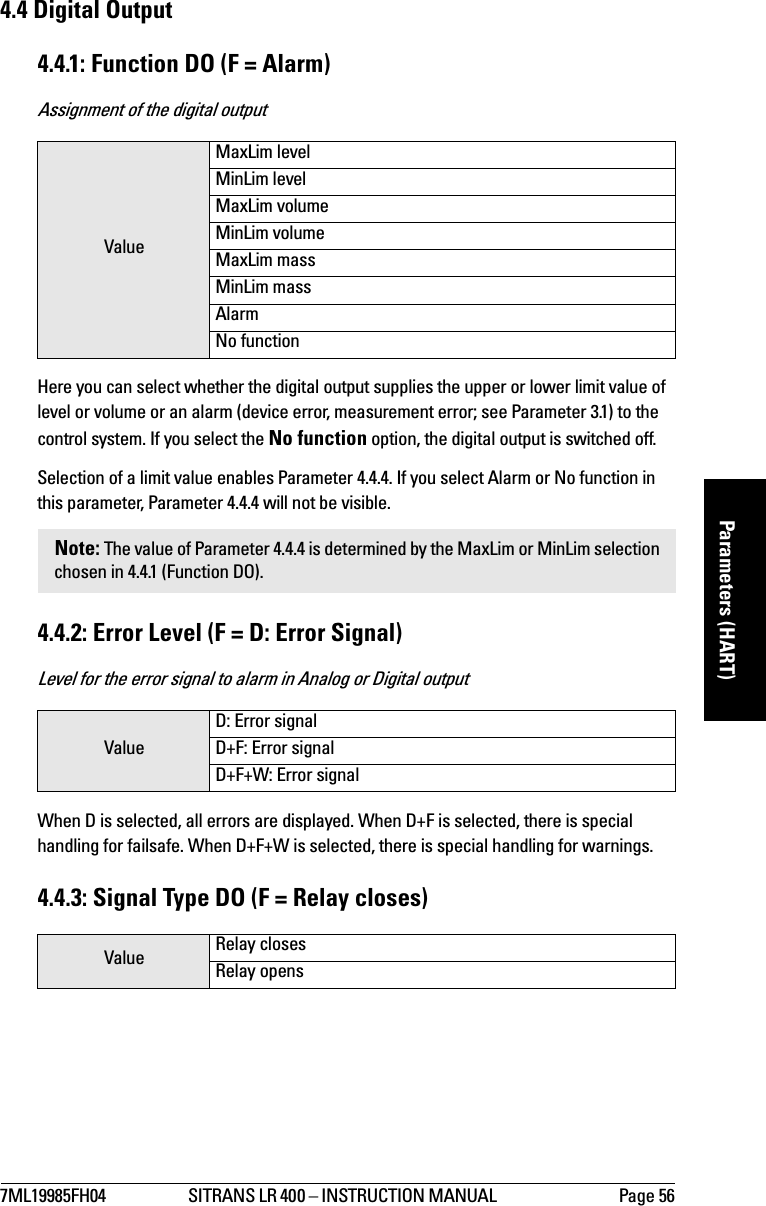
![7ML19985FH04 SITRANS LR 400 – INSTRUCTION MANUAL Page 19mmmmmInstallationBeam SpreadingCorrect Installation in Mounting NozzleThe bottom edge of the antenna must project into the vessel to avoid reflective interference at the wall of the nozzle. Above flange size DN 150/6", the antenna need not project beyond the nozzle unless the radiation cone (the extension of the antenna’s angle) touches the nozzle wall.Installation using Easy Aimer LRSITRANS LR 40013°9°Keep the emission cone (9° or 13° depending on configuration), free of obstructions.short horn antennalong horn antennaUpdated graphic required showing 2", 3" and 4" hornSITRANS LR 40010 mmtop clamping plate (upper socket)bottom clamping plate (lower socket)customer gasket [recommended thickness 1.5 to 1.8 mm (0.06 to 0.07")], as requiredcustomer mounting plate with at least ø 4" (102 mm) central opening, as required30° max.long horn 9.3"(235 mm) short horn 7.4"(188 mm)0.38" (10 mm)Graphic labels to be updated](https://usermanual.wiki/Siemens-Canada-Siemens-Milltronics-Process-Instruments/LR400-1/User-Guide-494773-Page-23.png)
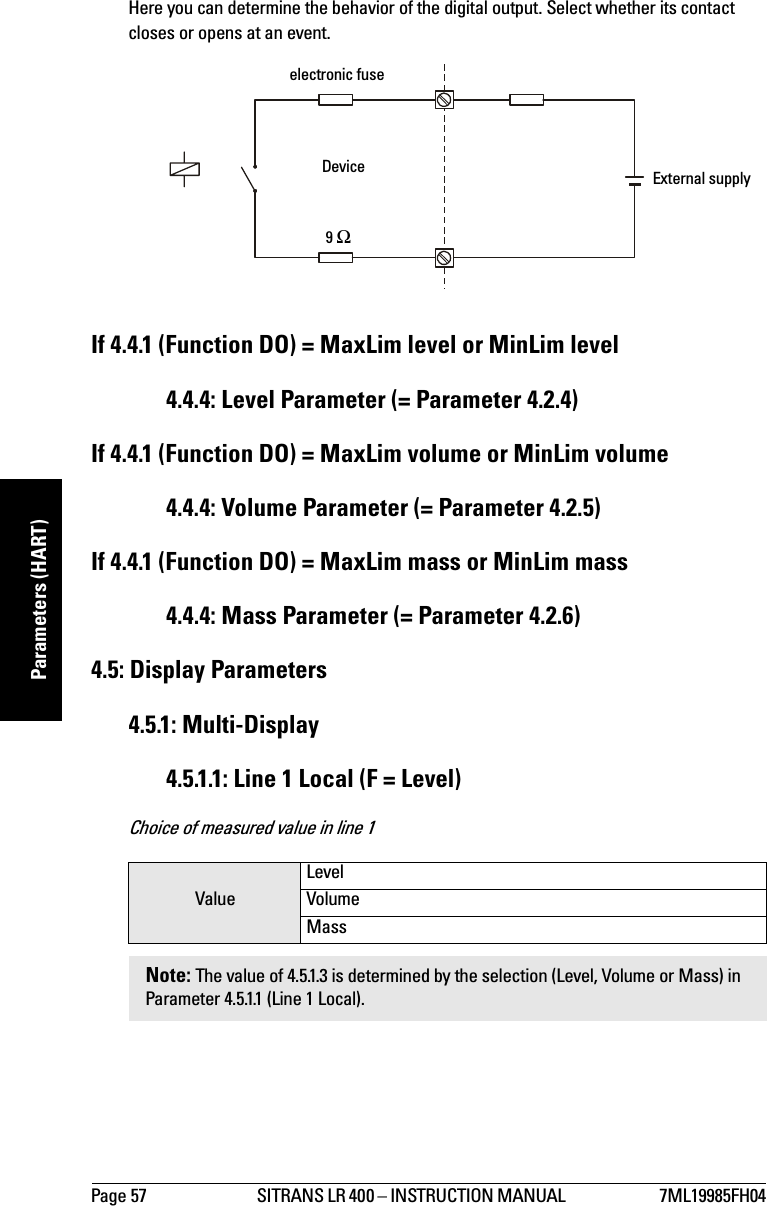
![7ML19985FH04 SITRANS LR 400 – INSTRUCTION MANUAL Page 21mmmmmInstallationConnecting the SITRANS LR 400:1. Release the cover lock on the connection box with a 3 mm Allen key.2. Unscrew the cover from the connection box.3. Push the power cable and signal cable through the cable gland on the right of the unit, up to the terminal strip. Lay the cable in a bend before the cable gland so that moisture cannot enter the connection box.4. Connect the earth conductor of the power supply to the earth terminal in the connection box. Adjust the cable length so that the earth conductor will be disconnected last if you pull on the cable.5. In devices with ignition protection types II 1/2G EEx dem [ia] IIC T6 and II 1/2G EEx dem [ib] IIC T6 or II 2G EEx dem [ia] IIC T6 and II 2G EEx dem [ib] IIC T6 (Liquids version), mount the cover for the power supply terminals.6. Tighten the cable screw gland and check the strain relief (pull and turn).7. In devices with ignition protection type II 1/2G EEx D IIC T6 or II 2G EEx d IIC T6 (Liquids version), replace unused screw-type cable glands with a certified dummy plug.8. Screw the cover onto the housing and tighten it without using a tool. The sealing ring must be clean and undamaged.9. Mount the cover lock of the connection box cover.10. Connect the earth terminal located between the screw-type cable glands to a ground connection at your vessel by using a cable of a cross-section at least 2.5 mm2.For error-free communication via the HART protocol, a load of at least 230 Ω must be available in the signal circuit.WARNING: • To avoid short-circuits, do not connect a load resistance with bare wires in the connection box.• The housing cover may not be unscrewed in a hazardous area when the device is under voltage (power supply, digital outputs on external supply). • In devices with ignition protection types II 1/2G EEx dem [ia] IIC T6 and II 1/2G EEx dem [ib] IIC T6 II 2G EEx dem [ia] IIC T6 and II 2G EEx dem [ib] IIC T6 (Liquids version), only the cover of the connection box may be unscrewed for test purposes. The cover on the power supply terminals may not be removed!](https://usermanual.wiki/Siemens-Canada-Siemens-Milltronics-Process-Instruments/LR400-1/User-Guide-494773-Page-25.png)
![Page 35 SITRANS LR 400 – INSTRUCTION MANUAL 7ML19985FH04mmmmmParameters (HART)1.7: Level damping (F = 1 s)Damping of level in sSet the damping of the level value in seconds. It acts on the analog output, the limit value monitor and the local display. For damping of the sensor signal, set Parameter 4.2.3.1. For slow moving solids applications, use a value of 500.1.8: Application Type (F - Liquid [process])Use of the vesselSelect Silo1 (solids) for tall, narrow silos. Select Silo 2 (solids) for large diameter silos, typically used for cement. In most cases, you set one of the pre-specified applications. The user vessels may adopt configurations which deviate from the factory settings. These are designed for special applications loaded at the factory or by service personnel. Additional Parameters2. Display2.1: Multi-display (F = level in mSignal to noise ratio in db)Display of two measured values. Values are determined in Parameter 4.5.1.1 (Line 1 Local) and in Parameter 4.5.1.4 (Line 2 Local).2.2: Level (F = m)Current level of measured medium (set unit using Length Unit in Auto-Setup)Value numerical valueValueLiquid (store)[Liquid]Liquid (process)[Liquid]Silo1 (solids)Silo2 (solids)User tank1User tank2Note: The following parameters cannot be accessed when you set a user vessel: Parameter 4.2.2.2 (Surface), Parameter 4.2.2.5 (Filling Speed), Parameter 4.2.2.6 (Reflectivity), and Sensor Parameters 4.2.3.1 (Sensor Damping), 4.2.3.2 (Multiple Echoes), 4.2.3.3 (Echo Motion), 4.2.3.4 (Window Tracking), and 4.2.3.5 (Tank Empty Detect). However, the parameters that remain under 4.2.2.x will be renumbered. See page 32 for more information on parameter renumbering.](https://usermanual.wiki/Siemens-Canada-Siemens-Milltronics-Process-Instruments/LR400-1/User-Guide-494773-Page-38.png)
![7ML19985FH04 SITRANS LR 400 – INSTRUCTION MANUAL Page 36mmmmmParameters (HART)2.3: Volume (F = m3)Volume of measured medium (set unit using Parameter 4.1.2 [Volume Unit])2.4: Mass (for qualified personnel only)This parameter is for Factory Authorized Personnel Only.2.5: Current OutputValue of the analog output in mAWhen the device electronics are working properly, the displayed current value will correspond to the measured output current.2.6: Digital OutputState of digital output3. Diagnostics3.1: StatusHere you can access current status messages of the device. Parameter 3.1.1 is always accessible; other parameters (Parameter 3.1.x) appear in the appropriate order if they contain error messages.3.1.1: Wear3.1.1.1: Operating HoursTotal previous operating time of the device in hours (approximate value)3.1.1.2: Maximum Temperature (F = 26 °C)Previous maximum internal temperature of the device3.1.1.3: Minimum Temperature (F = 26 °C)Previous minimum internal temperature of the device3.1.1.4: AgingApproximate value for the previous life of the device in % (100% = approx. 10 years)Note: This temperature must not exceed 85 °C (185 °F) or warranty may be void.](https://usermanual.wiki/Siemens-Canada-Siemens-Milltronics-Process-Instruments/LR400-1/User-Guide-494773-Page-39.png)
![Page 41 SITRANS LR 400 – INSTRUCTION MANUAL 7ML19985FH04mmmmmParameters (HART)4.1.4: Temperature Unit (F = °C)Unit of the sensor temperature4.1.5: Other units (F = SI)Units system for all other unitsWith this function, determine whether you want to enter the operating parameters (see Parameter 4.2) in SI or in British Imperial (US/UK) units. The selected units of the measured value output and sensor temperature as well as the decimal point are not influenced by this setting.4.2: Operating ParametersWith this parameter group, define the parameters of your vessel, the measuring medium and the calculation of the measured signal. Signal-specific default settings such as the failure signal or the upper current limit of the analog output signal are assigned to the functions of the respective outputs (see Parameters 4.3 and 4.4).4.2.1: Tank Geometry4.2.1.1: Nozzle Height = Parameter 1.34.2.1.2: Tank Height = Parameter 1.44.2.1.3: Stilling Pipe? (F = no) [Liquids]Stilling pipe available?By selecting yes or no, you specify whether the device is mounted on a stilling pipe. If you select yes, Parameter 4.2.1.3.2 is enabled so you can specify the internal diameter of the stilling pipe.Value°C°FKValue SI unitUS/UK unitValue YesNo](https://usermanual.wiki/Siemens-Canada-Siemens-Milltronics-Process-Instruments/LR400-1/User-Guide-494773-Page-44.png)
![7ML19985FH04 SITRANS LR 400 – INSTRUCTION MANUAL Page 42mmmmmParameters (HART)4.2.1.3.2: Pipe Diameter (F = 100 mm) [Liquids]Internal diameter of the stilling pipe4.2.2: Measuring Conditions4.2.2.1: Application Type (F - Liquid [process])Use of the vesselSelect Silo1 (solids) for tall, narrow silos. Select Silo 2 (solids) for large diameter silos typically used for cement. In most cases you set one of the pre-specified applications here. The user vessels may adopt configurations which deviate from the factory settings. These are designed for special applications loaded at the factory or by service. 4.2.2.2: Surface (F = wavy)Surface structure of the measuring medium. Not displayed if a user vessel is selected in Parameter 4.2.2.1.This parameter is not displayed when a user vessel is selected in Parameter 4.2.2.1. When used with poorly reflecting measuring media, you may be able to improve measuring results by setting a different surface structure here. If your measuring medium forms waves more than 1 cm in height, you should select the wavy setting. The turbulent setting is recommended for waves greater than 10 cm. Value numerical valueValueLiquid (store) [Liquids]Liquid (process) [Liquids]Silo1 (solids)Silo2 (solids)User tank1User tank2Note: The following parameters cannot be accessed when you set a user vessel: Parameter 4.2.2.2 (Surface), Parameter 4.2.2.5 (Filling Speed), Parameter 4.2.2.6 (Reflectivity), and Sensor Parameters 4.2.3.1 (Sensor Damping), 4.2.3.2 (Multiple Echoes), 4.2.3.3 (Echo Motion), 4.2.3.4 (Window Tracking), and 4.2.3.5 (Tank Empty Detect). However, the parameters that remain under 4.2.2.x will be renumbered. See page 32 for more information on parameter renumbering.ValueSmoothWavyTurbulent](https://usermanual.wiki/Siemens-Canada-Siemens-Milltronics-Process-Instruments/LR400-1/User-Guide-494773-Page-45.png)
![Page 61 SITRANS LR 400 – INSTRUCTION MANUAL 7ML19985FH04mmmmmParameters (Profibus PA)4.6.6: Descriptor (according to customer specifications)Measuring point description4.6.7: Message (according to customer specifications)Measuring point message, e.g. the date of the last check or clean4.6.8: Manufacturer Identification4.6.8.1: Serial Number (F = unique number)Factory serial number4.6.8.2: Order Number (according to customer specifications)Device order number (delivery state)4.6.8.3: Fld Device Revision (F = Number)Device version4.6.8.4: Software Revision (F = Number)4.6.8.5: Hardware Revision (F = Number)4.6.8.6: Antenna Offset (F = approx. 0.5 m [calibration value])Distance from sensor to flangeThe antenna offset defines the propagation time of the measuring signal between the sensor and the flange as a distance. It is preset at the factory and cannot be changed.Value up to any 16 charactersValue Up to any 32 charactersValue non-editableValue non-editableValue non-editableValue non-editableValue non-editable](https://usermanual.wiki/Siemens-Canada-Siemens-Milltronics-Process-Instruments/LR400-1/User-Guide-494773-Page-64.png)
![7ML19985FH04 SITRANS LR 400 – INSTRUCTION MANUAL Page 62mmmmmParameters (Profibus PA)4.6.8.7: Reference Difference (F = approx. 106 m [calibration value])Internal reference distanceThe length of the reference distance in the units system selected according to Parameter 4.1.5 is view-only. The device uses this value to calibrate itself so that no manual adjustment is necessary in long-term operation.5. Options5.1: Enter CodeInput of customer code to enable programmabilityThe device compares a code number which you enter here with the code defined in Parameter 5.2. If your entry matches the customer code completely, it releases the programming lock for all parameters. Any other code number locks and disables programming.5.2: Customer Code (F = 0)Determination of customer codeHere you define the customer code (up to nine digits), with which you can protect the device parameters against programming errors. It is strongly recommended that a customer code be entered after all programming is completed to secure the programmed values from changes.Use of the customer code is explained in Disabling and Enabling Programming on page 29.5.3: Factory Reset (F = no)Reset all parameters to factory settingThis parameter allows you to reset all parameters to the original factory setting as described in Parameters (HART) beginning on page 32.Value Customer codeValue Up to 9-digit codeValue YesNo](https://usermanual.wiki/Siemens-Canada-Siemens-Milltronics-Process-Instruments/LR400-1/User-Guide-494773-Page-65.png)
![Page 65 SITRANS LR 400 – INSTRUCTION MANUAL 7ML19985FH04mmmmmParameters (Profibus PA)3.3.1: Raw value Distance from flange to measured medium3.3.2: Echo amplitude Measure of quality of reflection3.3.3: S/N ratio Signal-to-noise ratio of the measured value in dB3.3.4: Validity Validity of the measured value in %3.3.5: Sensor temp Sensor temperature4: Device data4.1: Units4.1.1 Length unit = [1.2]4.1.2: Volume unit m3bblyd3ft3in3bushbbl (fl.)lm3hLGalImpGal4.1.3: Mass unit For qualified personnel only4.1.4: Temperature unitUnit of the sensor tem-perature°C °C°FK4.1.5: Other units Units system for all other unitsSI SI unitUS/UK unit4.2: Operating parameters4.2.1: Tank geometry4.2.1.1: Nozzle height = [1.3]4.2.1.2: Tank height = [1.4]4.2.1.3: Stilling pipe?[Liquids}Stilling pipe available? no yesnoParameters (PROFIBUS PA)Note: For parameter descriptions, please refer to the associated HART parameters on pages 30 to 58.Parameter, menu identification Description Factory SettingSetting Possibilities](https://usermanual.wiki/Siemens-Canada-Siemens-Milltronics-Process-Instruments/LR400-1/User-Guide-494773-Page-68.png)
![7ML19985FH04 SITRANS LR 400 – INSTRUCTION MANUAL Page 66mmmmmParameters (Profibus PA)If yes, 4.2.1.3.2: Pipe diameter[Liquids}Diameter (internal) of the stilling pipe100 mm numerical value4.2.2: Measuring conditions 4.2.2.1: Applic. type Use of the tank Liquid (pro-cess)Liquid (store)Liquid (process)Silo1 (solids-pel-lets)Silo2 (solids-pow-ders)User tank1User tank24.2.2.2: Surface Surface structure of themeasured mediumNot displayed if a user tank is selected in [4.2.2.1].wavy smoothwavyturbulent4.2.2.3: Dead band Area beneath the flange in which measured val-ues are ignored0.4 m numerical value,Minimum value = Length of the antenna4.2.2.4: Correction factorCorrection factor for physical measuring influ-ences1.0 numerical value4.2.2.5: Filling speed Typical speed of change of the levelNot displayed if a user tank is selected in [4.2.2.1].200 mm/min numerical value4.2.2.6 Reflectivity For qualified personnel only4.2.2.7: Failsafe level Selects the default mea-surement in the event the failsafe timer expiresHold 100 %0 %Hold4.2.2.8: Failsafe timer Sets the time delay, in minutes, before going into fail-safe level10 min 1 min2 minetc.4.2.2.9: Range exten-sionSets the distance below the tank height included in the evaluation3 m 1 m2 metc.Parameters (PROFIBUS PA)Note: For parameter descriptions, please refer to the associated HART parameters on pages 30 to 58.Parameter, menu identification Description Factory SettingSetting Possibilities](https://usermanual.wiki/Siemens-Canada-Siemens-Milltronics-Process-Instruments/LR400-1/User-Guide-494773-Page-69.png)
![Page 67 SITRANS LR 400 – INSTRUCTION MANUAL 7ML19985FH04mmmmmParameters (Profibus PA)4.2.3: Sensor param-eter4.2.3.1: Sensor damp-ingAveraging of measuring signalNot displayed if a user tank is selected in [4.2.2.1].1 s numerical value4.2.3.2: Multiple echo Evaluate multiple echo on onoff4.2.3.3: Echo motion Evaluate echo motion on onoff4.2.3.4: Window trackingEvaluate moving targets off onoff4.2.3.5: Tank empty detectFor qualified personnel only4.2.3.6: Auto fix dis-tanceFor qualified personnel only4.2.3.7: Fix Dist List For qualified personnel only4.2.3.7.1 to 4.2.3.7.9: Fix Dist List valuesFor qualified personnel only4.2.3.8: Auto False Echo suppressionLearns and records the current signal up to the suppression distance set-ting. These signals are then ignored during oper-ation.use userecordoff4.2.3.9: Auto False Echo suppression distanceDefines the end point of the Auto False Echosuppression distance2/3 tank heightvariable4.2.3.A Hover level Defines (in %) how high the TVT curve is placed above echo profile, rela-tive to largest echo40% 0 to 100%4.2.3.B Window TriggerDefines position of win-dow on leading edge of selected echo, relative to amplitude80% 0 to 100%4.2.4: Level param.4.2.4.1: Level URV = [1.5]Parameters (PROFIBUS PA)Note: For parameter descriptions, please refer to the associated HART parameters on pages 30 to 58.Parameter, menu identification Description Factory SettingSetting Possibilities](https://usermanual.wiki/Siemens-Canada-Siemens-Milltronics-Process-Instruments/LR400-1/User-Guide-494773-Page-70.png)
![7ML19985FH04 SITRANS LR 400 – INSTRUCTION MANUAL Page 68mmmmmParameters (Profibus PA)4.2.4.2: Level LRV = [1.6]4.2.4.3: Level damp-ing= [1.7]4.2.4.4: MinWarn levelLimit before reaching lower limit value0 m numerical value4.2.4.5: MinLim level Lower limit value of the level (See Functional Dimensions Diagram)0 m numerical value4.2.4.6: MaxLim level Upper limit value of the level (See Functional Dimensions Diagram)20 m numerical value4.2.4.7: MaxWarn levelLimit before reaching upper limit value20 m numerical value4.2.4.8: HYST level Hysteresis of the level limit values0.5 m numerical value4.2.5: Volume param.4.2.5.1: Volume URV Full scale of the volume 20 m3numerical value4.2.5.2: Volume LRV Start of scale of the vol-ume0 m3numerical value4.2.5.3: Volume dampingDamping of the volume 1 s numerical value4.2.5.4: MinWarn vol-umeLimit before reaching lower limit value0 m3numerical value4.2.5.5: MinLim vol-umeLower limit value of the volume0 m3numerical value4.2.5.6: MaxLim vol-umeUpper limit value of the volume20 m3numerical value4.2.5.7: MaxWarn volumeLimit before reaching upper limit value20 m numerical value4.2.5.8: HYST volume Hysteresis of the volume limit values0.5 m3numerical value4.2.5.9: Tank charac-teristicDetermining the tank characteristicCalculate Calibrate/tableCalculate4.2.5.A: Calibrate/tableor 4.2.5.A: CalculateParameters (PROFIBUS PA)Note: For parameter descriptions, please refer to the associated HART parameters on pages 30 to 58.Parameter, menu identification Description Factory SettingSetting Possibilities](https://usermanual.wiki/Siemens-Canada-Siemens-Milltronics-Process-Instruments/LR400-1/User-Guide-494773-Page-71.png)
![Page 69 SITRANS LR 400 – INSTRUCTION MANUAL 7ML19985FH04mmmmmParameters (Profibus PA)4.2.5.A.1: Calibrateor4.2.5.A.1: Tank designAutomatic litering Confirm inputVertical cylin-derLinearVertical cylinderHorizontalCylinderSphere4.2.5.A.2: Enter tableor4.2.5.A.2: Bottom designManual entry of a table numerical valueDished end Dished endBasket endBullet bottom4.2.5.A.3: Show tableor4.2.5.A.3: Tank vol-umeDisplay table Selection20 m3numerical value4.2.5.A.4: Clear tableor4.2.5.A.4: Tank heightDelete table Selection= [4.2.1.2]4.2.6: Mass Parame-tersFor qualified personnel only4.2.6.1: Mass URV For qualified personnel only4.2.6.2: Mass LRV For qualified personnel only4.2.6.3: Mass damp-ingFor qualified personnel only4.2.6.4: MinWarn MassFor qualified personnel only4.2.6.5: MinLim mass For qualified personnel only4.2.6.6: MaxLim mass For qualified personnel only4.2.6.7: MaxWarn MassFor qualified personnel only4.2.6.8: HYST Mass For qualified personnel only4.2.6.9: Tank Charac-terFor qualified personnel only4.2.6.A: Calibrate/tableor 4.2.6.A: Calculate4.2.6.A.1: Calibrateor4.2.6.A.1: Tank designFor qualified personnel onlyFor qualified personnel onlyParameters (PROFIBUS PA)Note: For parameter descriptions, please refer to the associated HART parameters on pages 30 to 58.Parameter, menu identification Description Factory SettingSetting Possibilities](https://usermanual.wiki/Siemens-Canada-Siemens-Milltronics-Process-Instruments/LR400-1/User-Guide-494773-Page-72.png)
![7ML19985FH04 SITRANS LR 400 – INSTRUCTION MANUAL Page 70mmmmmParameters (Profibus PA)4.2.6.A.2: Enter tableor4.2.6.A.2: Bottom designFor qualified personnel onlyFor qualified personnel only4.2.6.A.3: Show tableor4.2.6.A.3: Tank vol-umeFor qualified personnel onlyFor qualified personnel only4.2.6.A.4: Clear tableor4.2.6.A.4: Tank heightFor qualified personnel onlyFor qualified personnel only4.2.6.B: Density For qualified personnel only4.2.7.x: User Parame-ters 1For qualified personnel only4.2.8.x: User Parame-ters 2For qualified personnel only4.3: Output parame-ter4.3.1: BusIdentNr. Profile specificManufacturer spe-cific4.3.2: Bus address = [1.8}4.4: Display param.4.4.1: Multi display4.4.1.1: Line 1 local Choice of measured value in line 1Level LevelVolumeMass4.4.1.2: Display local Method of display in line 1Eng unit Eng unit%Bargraph4.4.1.3: Level param.or4.4.1.3: Volume param.or4.4.1.3: Mass param.= [4.2.4]= [4.2.5]= [4.2.6]Parameters (PROFIBUS PA)Note: For parameter descriptions, please refer to the associated HART parameters on pages 30 to 58.Parameter, menu identification Description Factory SettingSetting Possibilities](https://usermanual.wiki/Siemens-Canada-Siemens-Milltronics-Process-Instruments/LR400-1/User-Guide-494773-Page-73.png)
![Page 71 SITRANS LR 400 – INSTRUCTION MANUAL 7ML19985FH04mmmmmParameters (Profibus PA)4.4.1.4: Line 2 local Display in line 2 S/N ratio LevelVolumeMassTemperatureValidityS/N ratioAmplitudeDigital outputAnalog output4.4.1.5: Level param.or4.4.1.5: Volume param.or4.4.1.5: Mass param.= [4.2.4]= [4.2.5]= [4.2.6]4.4.2: Language local = [1.1]4.4.3: LCD backlight Background illumination of the LCDoff onoff4.5: Device info4.5.1: Power supply Voltage range of the built-in power supply unitaccording to customer specifica-tionsnon-editable4.5.2: Process temperatureTemperature range of the flange in °Caccording to customer specifica-tionsnon-editable4.5.3: Electrical con-nectionaccording to customer specifica-tionsnon-editable4.5.4: Antenna and flange4.5.4.1: Flange size Rated size of the flange according to customer specifica-tionsDN 50, 2"DN 80, 3" DN 100, 4"DN 150, 6"Special designParameters (PROFIBUS PA)Note: For parameter descriptions, please refer to the associated HART parameters on pages 30 to 58.Parameter, menu identification Description Factory SettingSetting Possibilities](https://usermanual.wiki/Siemens-Canada-Siemens-Milltronics-Process-Instruments/LR400-1/User-Guide-494773-Page-74.png)