Siemens Canada Siemens Milltronics Process Instruments LR460 SITRANS LR 460 TANK LEVEL PROBING RADAR User Manual JM01 LR460
Siemens Canada Ltd. - Siemens Milltronics Process Instruments SITRANS LR 460 TANK LEVEL PROBING RADAR JM01 LR460
UserManual.wiki
>
Siemens Canada Siemens Milltronics Process Instruments
>
LR460 User Manual
USERS MANUAL
Navigation menu
Upload a User Manual
Namespaces
Wiki Guide
HTML
PDF
Info
Views
User Manual
Discussion / Help
Navigation
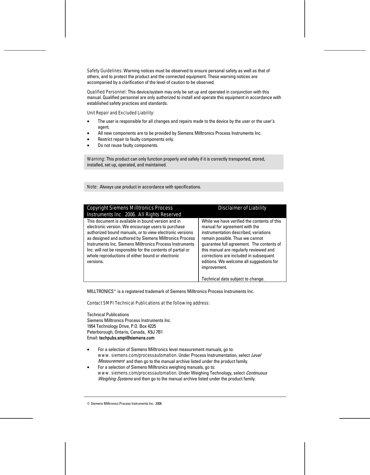
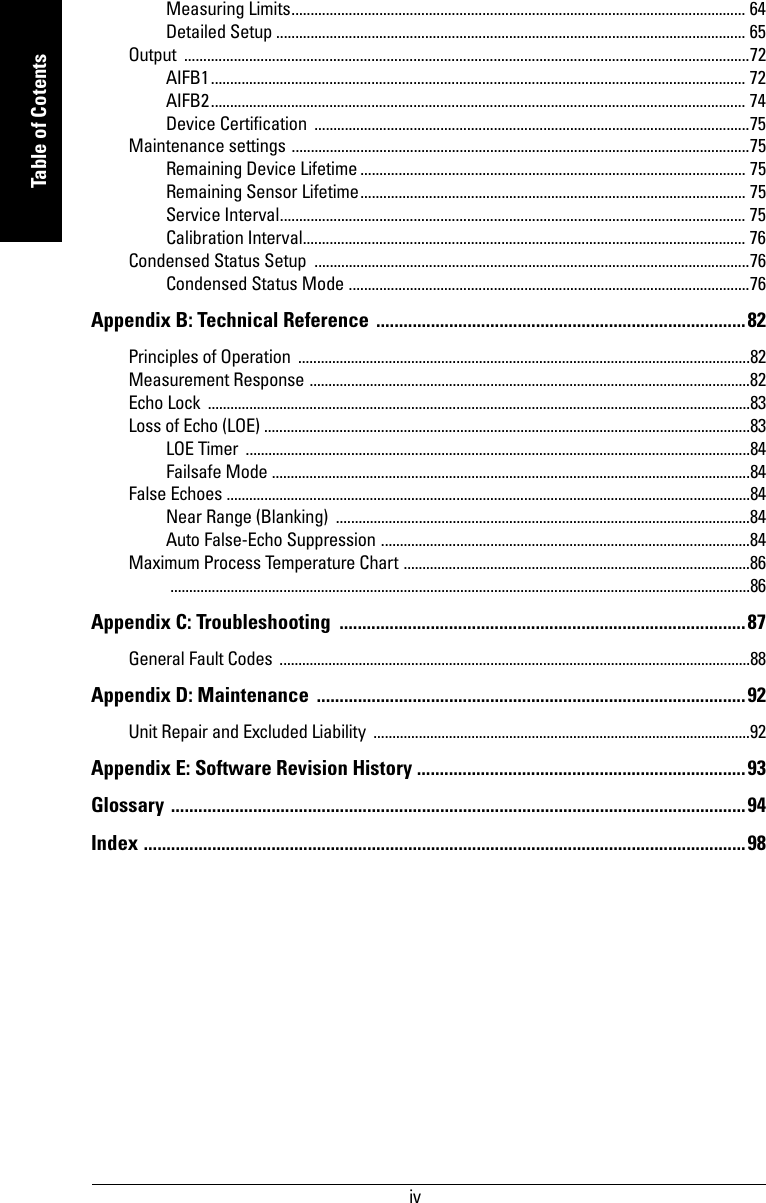

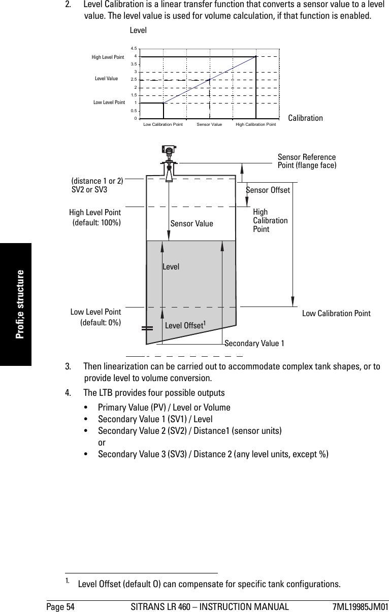
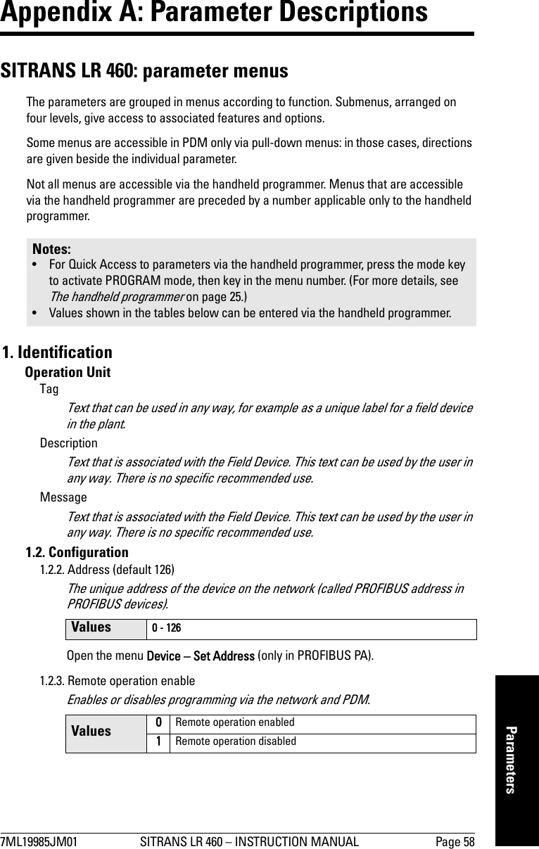
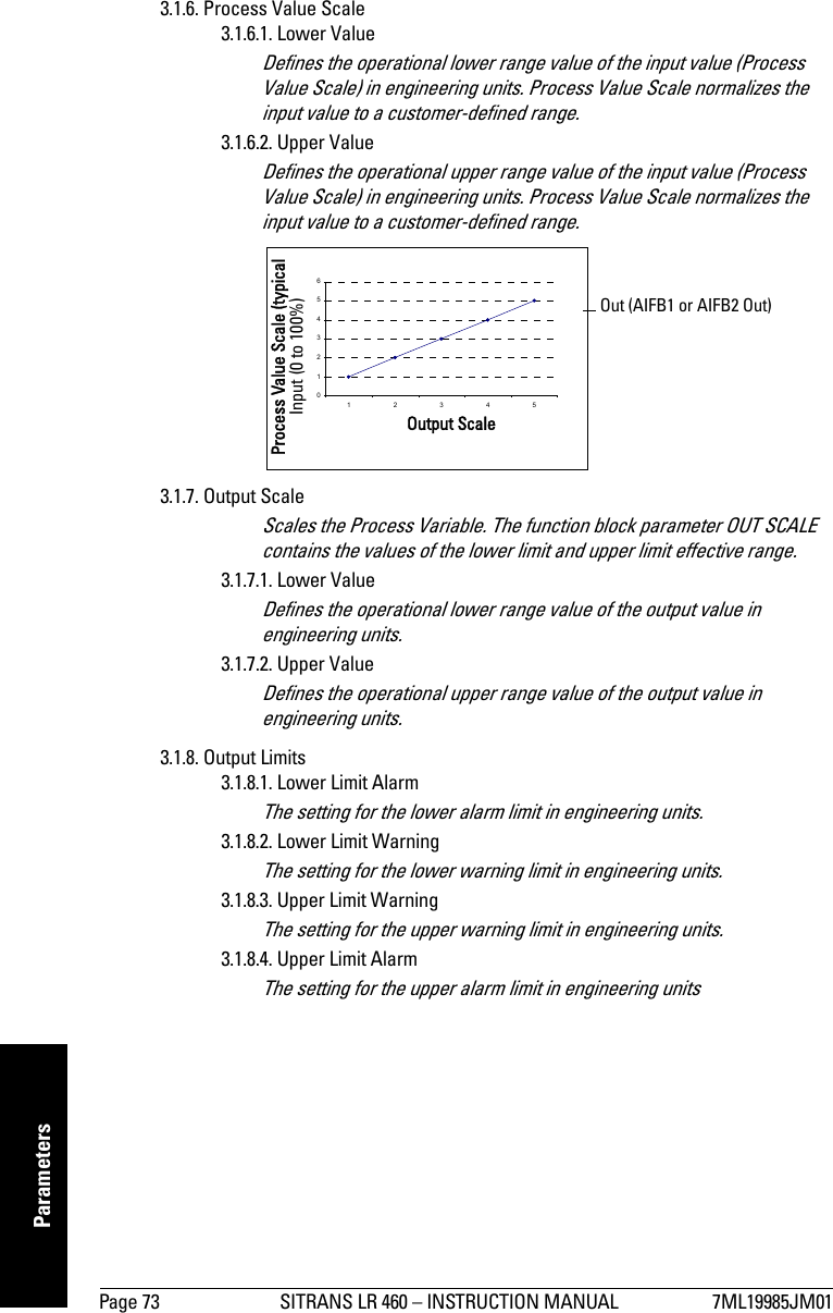
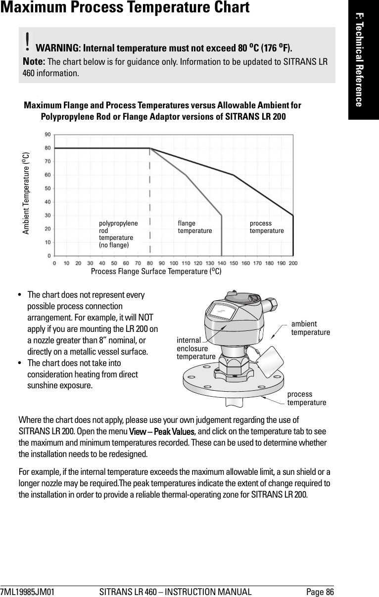
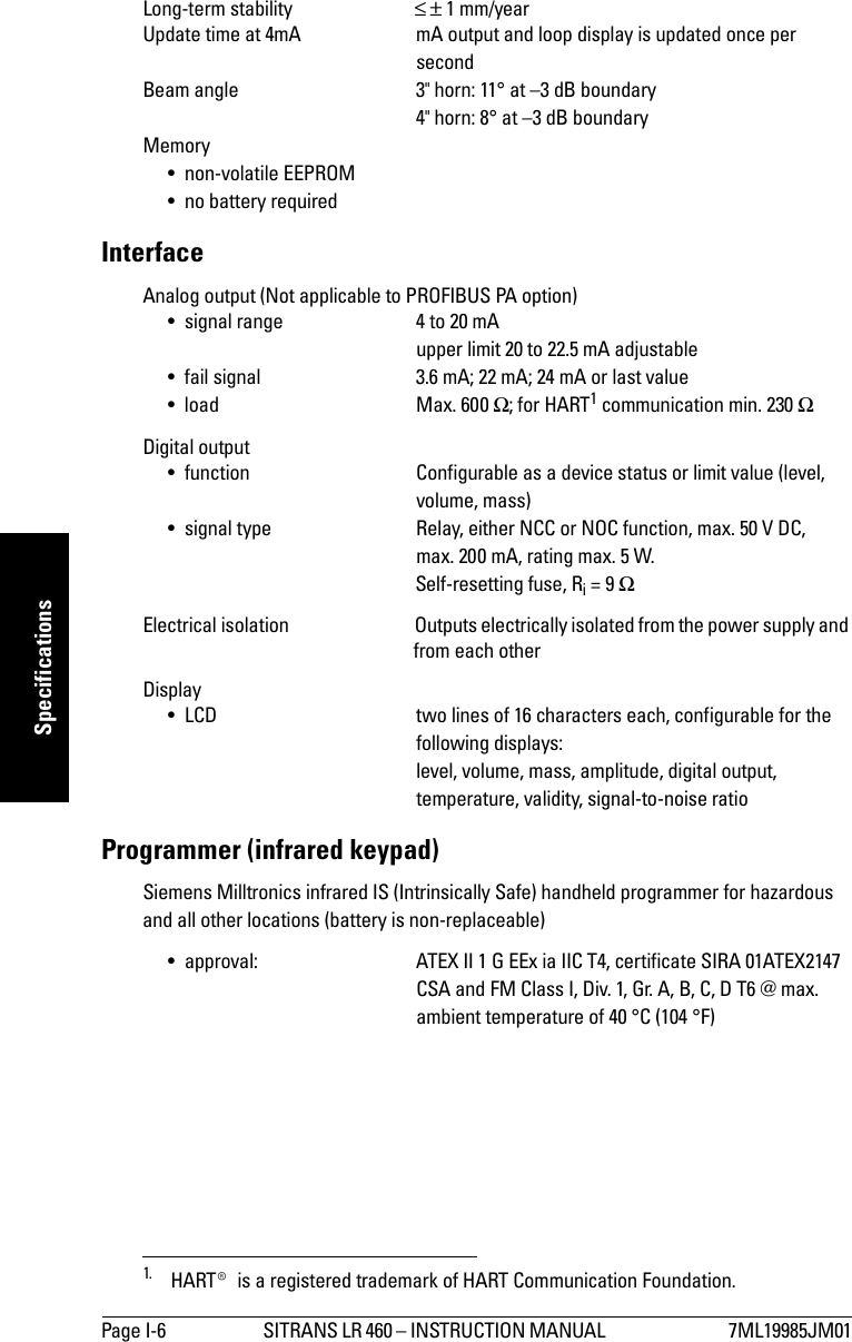
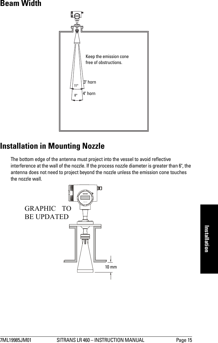
![7ML19985JM01 SITRANS LR 460 – INSTRUCTION MANUAL PageI-5mmmmmSpecificationsSpecificationsSITRANS LR 460PowerPower Supply (HART)• 100 to 230 V AC, ±15%, 50/60 Hz, 6 W (12VA) • 24 V DC, +25/-20%, 6 W• Power failure: bridge of at least 1 mains period (> 20 ms)• Fuse (AC ) SI1 Fast acting ceramic, 4 x 20 mm, 1 A, 250 V ACSI2 Slow-Blow, 4 x 20 mm, 0.63 A, 250 V AC• Fuse (DC ) SI1 Fast acting ceramic, 4 x 20 mm, 2 A, 250 V ACSI2 Slow-Blow, 4 x 20 mm, 0.63 A, 250 V ACPower Supply (PROFIBUS PA)PerformanceReference operating conditions according to IEC 60770-1• ambient temperature +15 to +25 oC• humidity 45 to 75 % relative humidity• ambient pressure 860 to 1060 mbar (12.47 to 15.37 psi)Measurement Accuracy (measured in accordance with IEC 60770-1)• non-linearity (accuracy) greater of 25 mm (1”) or 0.25% of span (including hysteresis and non-repeatability)• non-repeatability 10 mm (0.4”) [included in non-linearity specification]• deadband (resolution) 10 mm (0.4”) [included in non-linearity specification]• hysteresis error 0 mmAnalog Output Accuracy (measured in accordance with IEC 60770-1)• non-linearity (accuracy) 0.100% of span (including hysteresis and repeatability)• non-repeatability 0.030% of span (included in non-linearity specification)• deadband (resolution) 0.030% of span [included in non-linearity specification]• hysteresis error 0%Frequency 25 GHz nominalMeasurement range 0.35 to 70 m (1.15 to 229.66 ft)1Note: Siemens Milltronics makes every attempt to ensure the accuracy of these specifications, but reserves the right to change them at any time. 1. Minimum range: 0.35 m (1.15 ft) from bottom of flange.](https://usermanual.wiki/Siemens-Canada-Siemens-Milltronics-Process-Instruments/LR460/User-Guide-635569-Page-15.png)
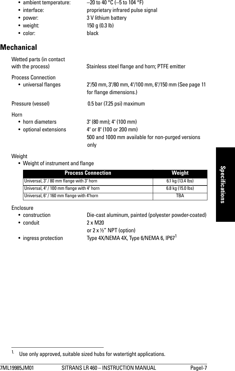
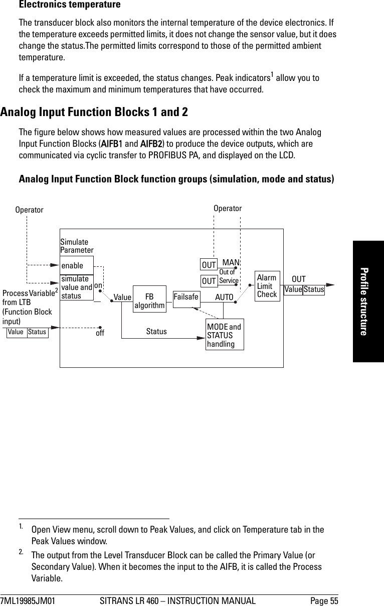
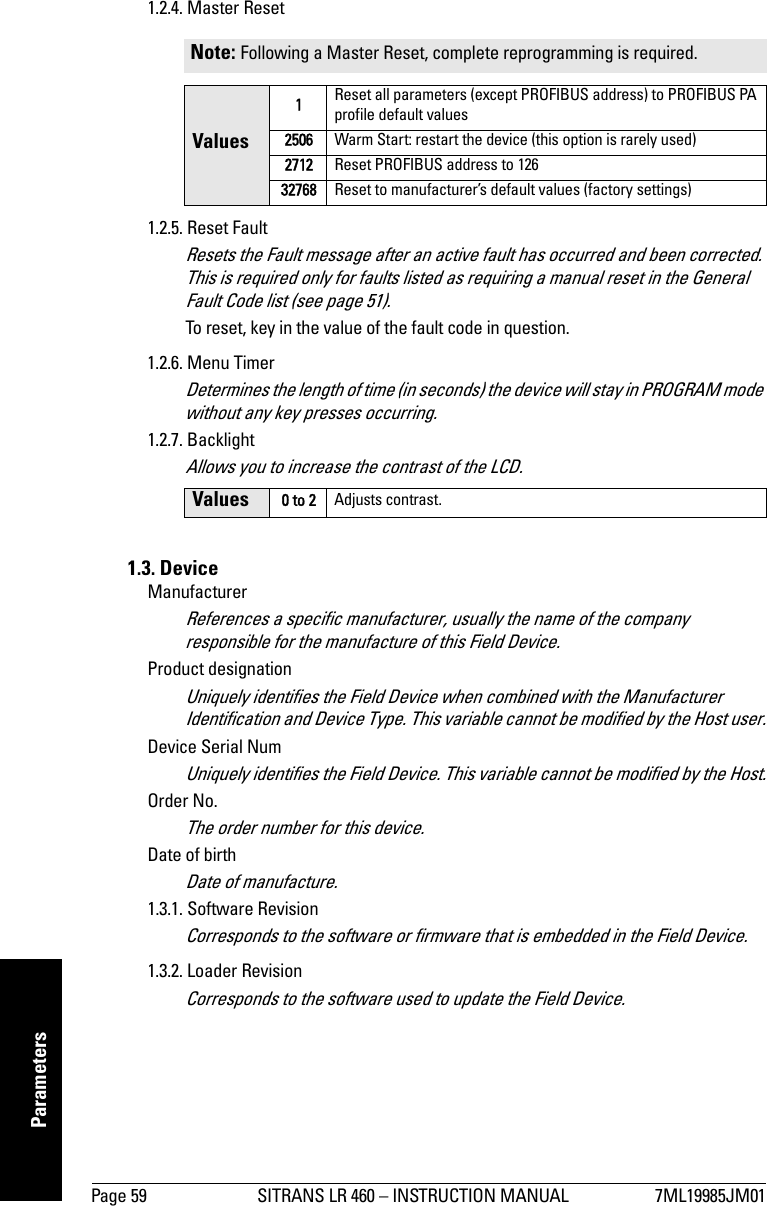
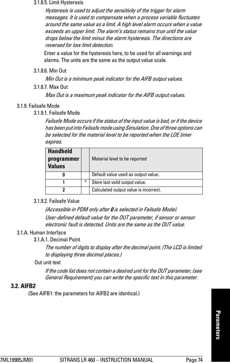
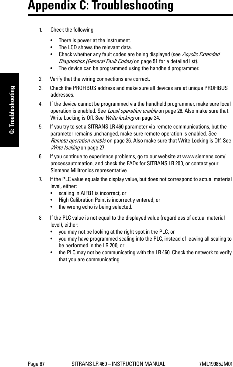
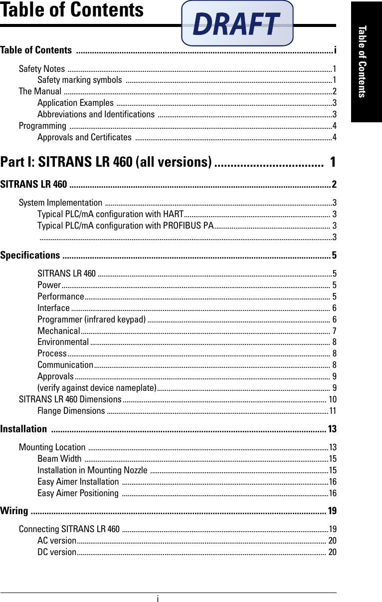
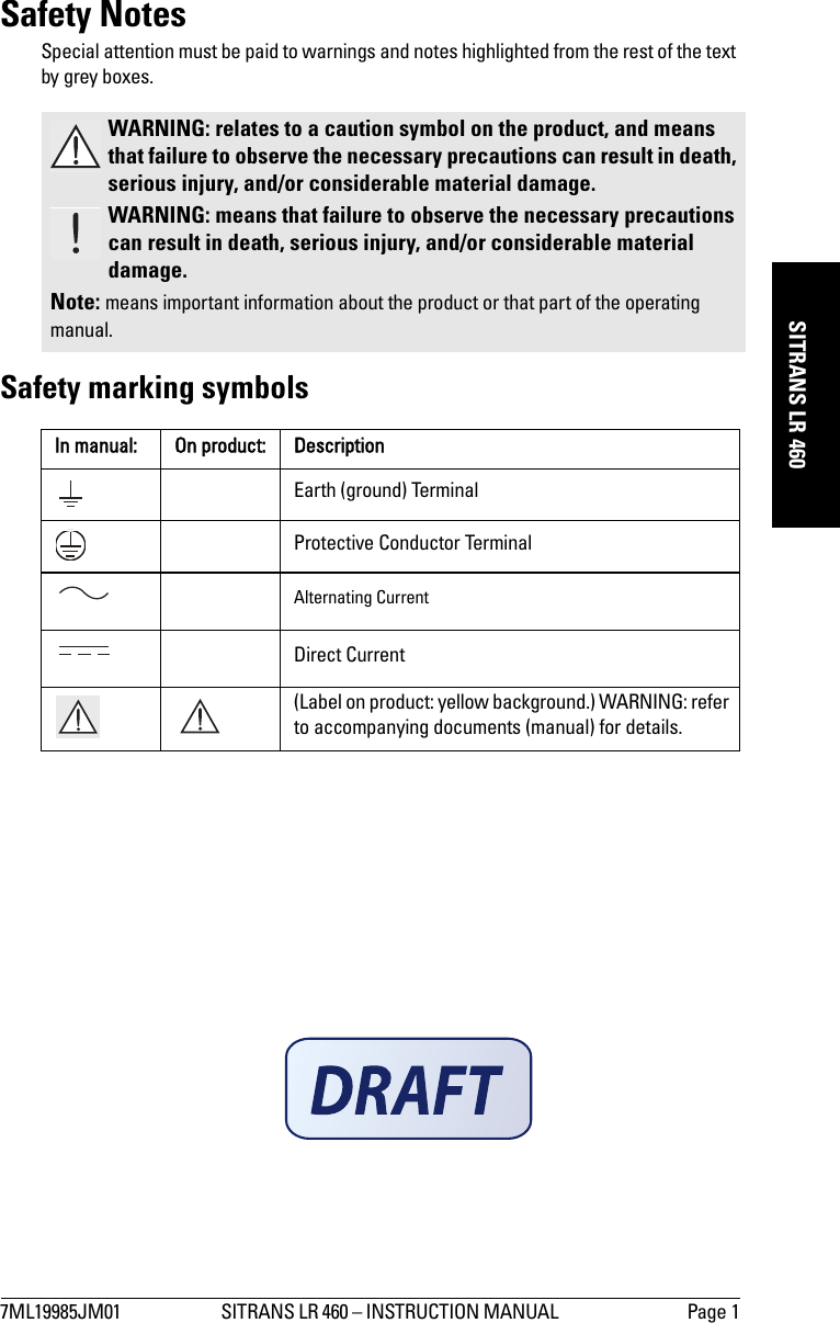
![Page I-8 SITRANS LR 460 – INSTRUCTION MANUAL 7ML19985JM01mmmmmSpecificationsEnvironmental1• location indoor/outdoor• altitude 2000 m (6562 ft) max• ambient temperature2-40 to 65 °C (-40 to 149 °F)• relative humidity suitable for outdoor (Type / NEMA 4X, 6/ IP67)• installation category II• pollution degree 4• Perm. ambient -40 to 65 °C (-40 to 149 °F) (non-hazardous version)temperature3LCD: -10 to 55 °C (14 to 131 °F)Observe the temperature classes in hazardous areas!Process• Process temperature -40 to 200 °C (-40 to 392 °F)[-40 to 250 °C (-40 to 418 °F) option]• Pressure (vessel) 0.5 bar (7.25 psi) maximumCommunication• Communication: HARTLoad 230 to 600 Ω, 230 to 500 Ω when connecting a couplingmoduleLine two-wire shielded: ≤ 3000 mmulti-wire shielded: ≤ 1500 mProtocol HART, Version 5.1• Communication: PROFIBUS PAProtocol Layer 1 and 2 PROFIBUS PA, technology: IEC 61158-2, slave-functionalityDevice Class ADevice Profile 3.0• Software for PC/Laptop Windows 95/98/2000/XP or NT 4.0SIMATIC® PDM1. See Process/Ambient de-rating curves in Appendix III.2. -20 °C (-4 °F) temperature rating available on SITRANS LR 460 with ATEX rating.WARNING: Materials of construction are chosen based on their chemical compatibility (or inertness) for general purposes. For exposure to specific environments, check with chemical compatibility charts before installing.](https://usermanual.wiki/Siemens-Canada-Siemens-Milltronics-Process-Instruments/LR460/User-Guide-635569-Page-18.png)
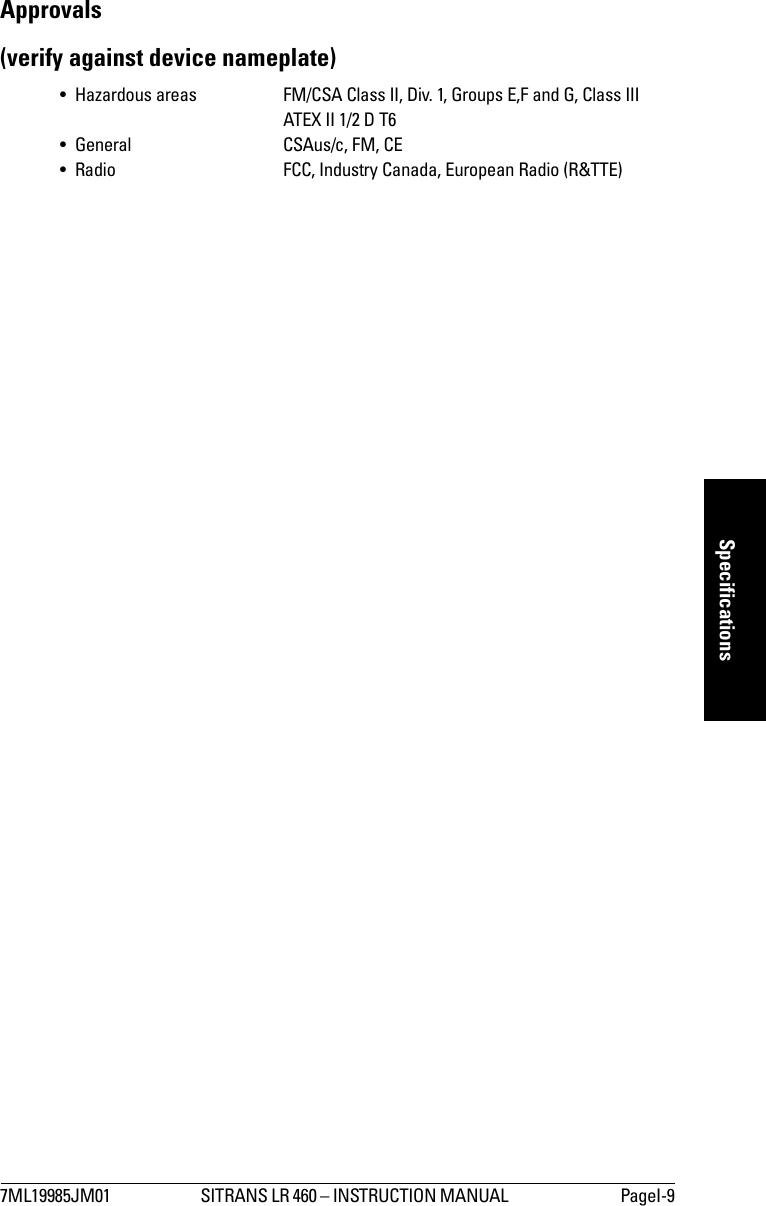
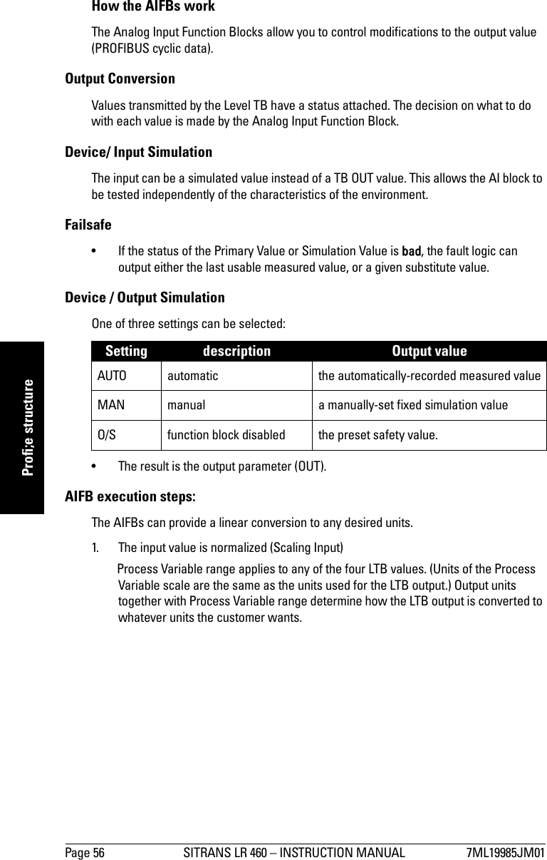
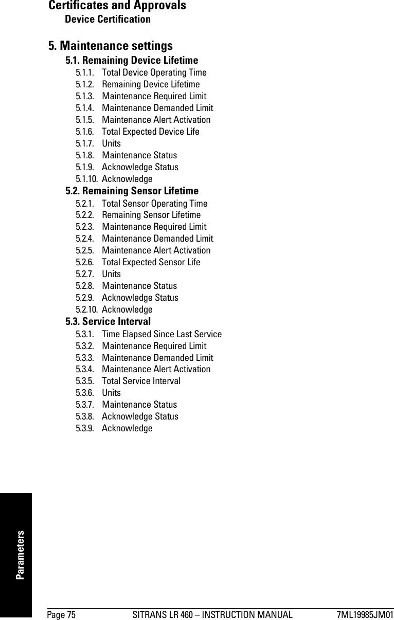
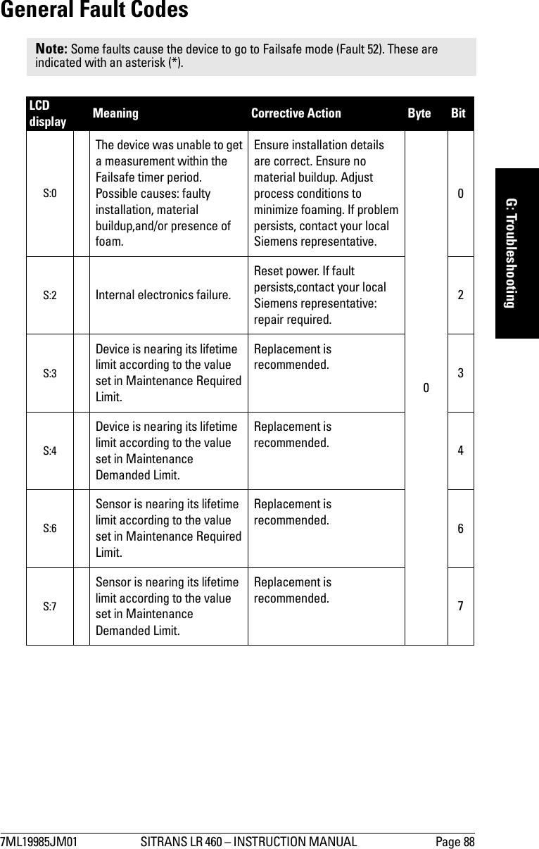
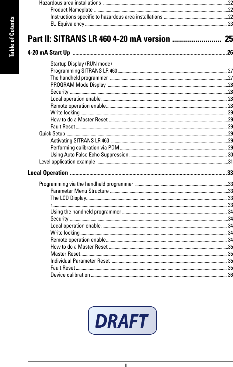
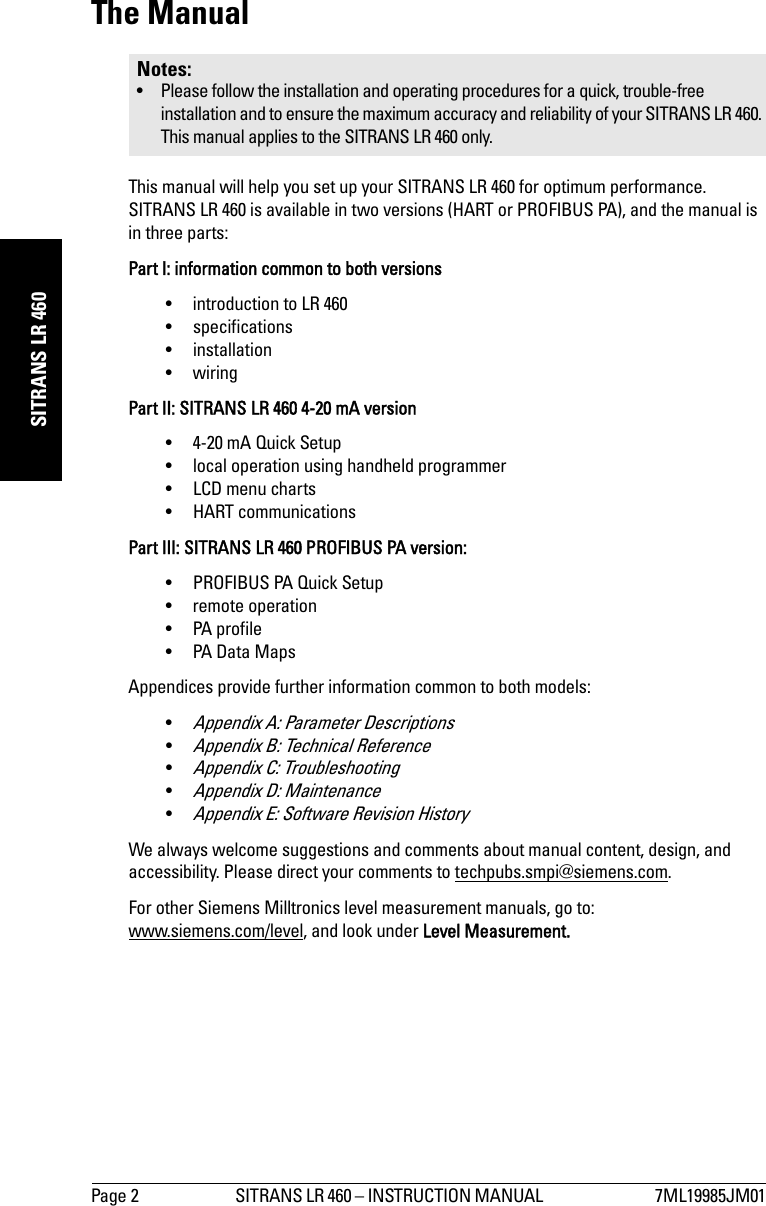
![Page 16 SITRANS LR 460 – INSTRUCTION MANUAL 7ML19985JM01mmmmmInstallationEasy Aimer InstallationEasy Aimer Positioning• Direct SITRANS LR 460 so the horn antenna is pointed at an angle to the filling level as shown. • Loosen the Easy Aimer ball locking bolts and position the LR 460. • Tighten bolts to secure the device.top clamping plate (upper socket)bottom clamping plate (lower socket)customer gasket as required[recommended thickness 1.5 to 1.8 mm (0.06 to 0.07")]customer mounting plate, as requiredø 4" (102 mm) min., central opening30° max.2" horn: 6.5" (165.5 mm)3" horn: 9.0" (228.3 mm) 4" horn: 11.5" (291.2 mm)0.38" (10 mm)Easy Aimer ball locking boltsSITRANS LR 400Easy Aimer](https://usermanual.wiki/Siemens-Canada-Siemens-Milltronics-Process-Instruments/LR460/User-Guide-635569-Page-26.png)

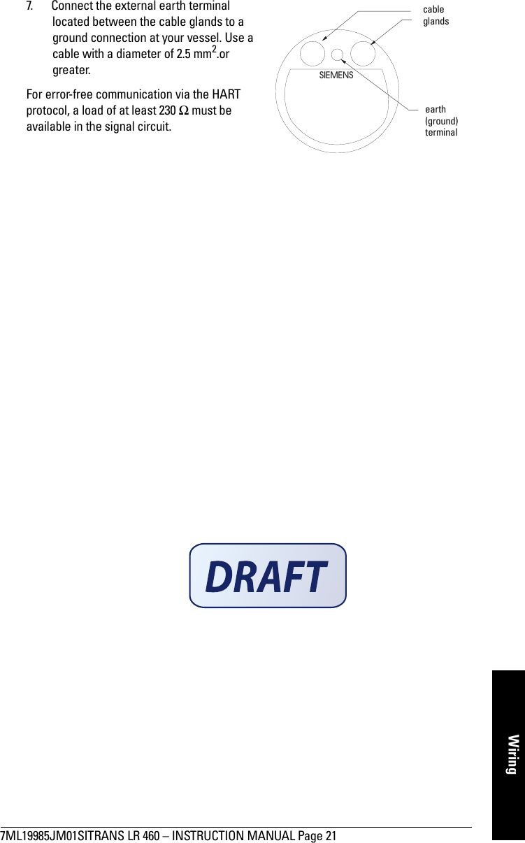
![7ML19985JM01SITRANS LR 460 – INSTRUCTION MANUAL Page 23mmmmmWiring• Permitted ambient temperature at the horn antenna (Category 1D):- 20 °C ≤ Tamb ≤ +200 °C• Permitted ambient temperature at the electronic enclosure (Category 2D):-20 °C ≤ Tamb ≤ +65 °C• Maximum permitted temperature within electronic enclosure (Category 1D): 85 °C4. The equipment has not been assessed as a safety related device (as referred to by Directive 94/9/EC Annex II, clause 1.5).5. Installation and inspection of this equipment shall be carried out by suitably trained personnel in accordance with the applicable code of practice (EN 60079-14 and EN 60079-17 in Europe).6. Repair of this equipment shall be carried out by suitably trained personnel in accordance with the applicable code of practice (e.g. EN 60079-19 within Europe).7. Components to be incorporated into or used as replacements in the equipment shall be fitted by suitably trained personnel in accordance with the manufacturer's documentation.8. It is the responsibility of the user to ensure that manual override is possible in order to shut down the equipment and protective systems incorporated within automatic processes, which deviate from the intended operating conditions, provided that this does not compromise safety.9. Equipment Marking:The equipment marking contains at least the information on the product label, shown on page 22.EU Equivalency Any zener diode safety barrier, certified by an EU approved certification body to [ EEx ia ] IIC, its output voltage (Uo) not exceeding 24 V and its output current (Io) limited by load resistance (Ro); such that Io = Uo / Ro, does not exceed 250 mA. Ambient temperature at the horn antenna (Category 1D)Maximum surface temperature at the horn antenna (Category 1D)Maximum surface temperature Category 2D (electronic enclosure resp. flange)- 20 °C ≤ Tamb ≤ + 60 °C 72 °C 70 °C at Tamb ≤ 65 °C in Category 2- 20 °C ≤ Tamb ≤ + 100 °C 112 °C 100 °C independent from Tamb in Category 2- 20 °C ≤ Tamb ≤ + 200 °C 212 °C 200 °C independent from Tamb in Category 2Notes • The installation must comply with national requirements. • The safe area is unspecified except that it must not be supplied from nor contain, under normal or abnormal conditions, a source of potential with respect to earth in excess of 250 V rms or 250 V DC.](https://usermanual.wiki/Siemens-Canada-Siemens-Milltronics-Process-Instruments/LR460/User-Guide-635569-Page-33.png)

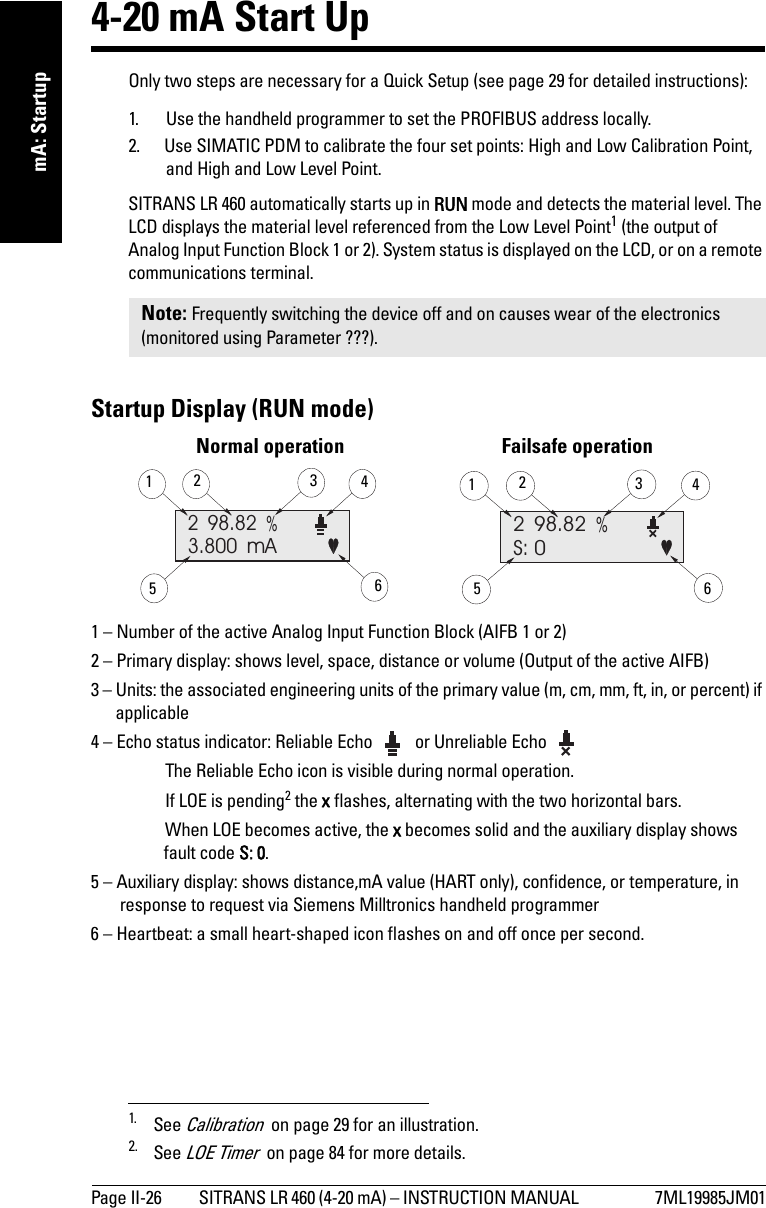
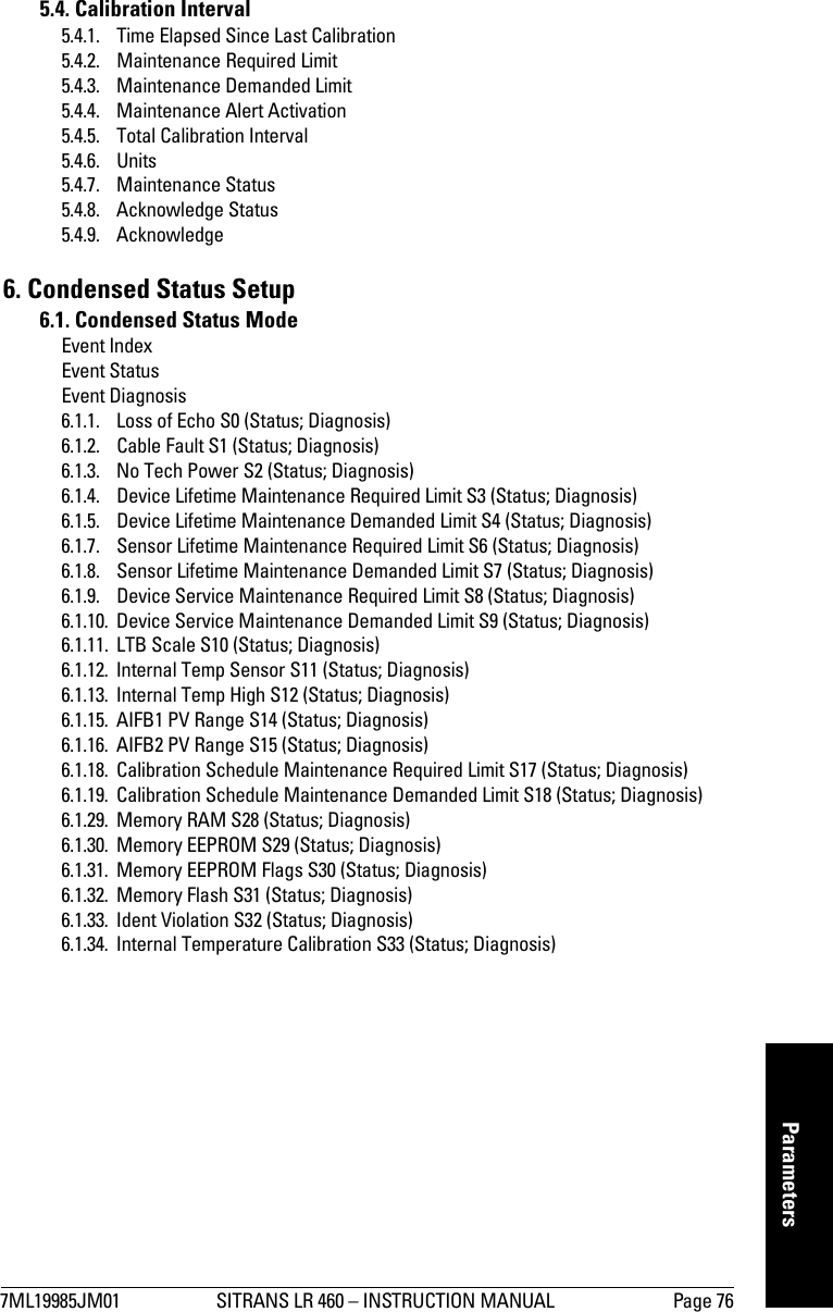
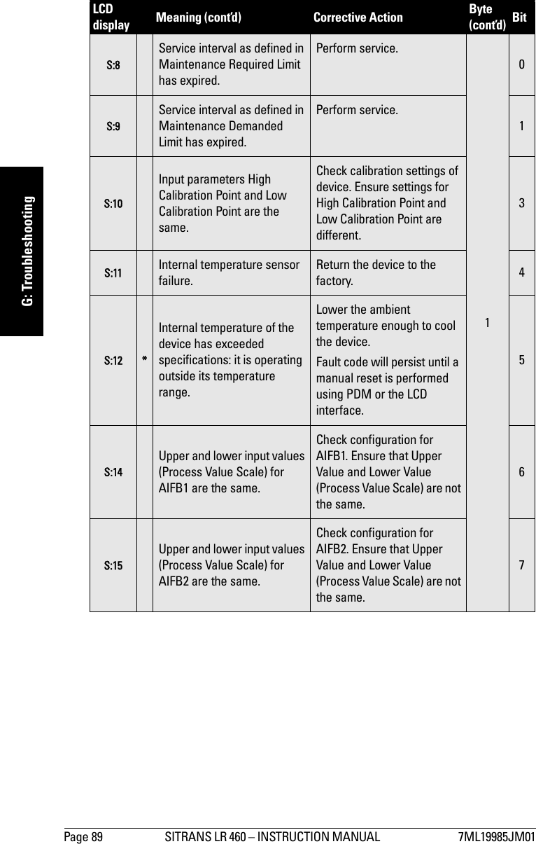
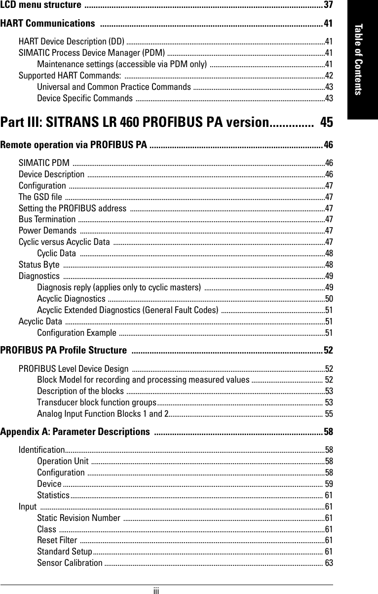
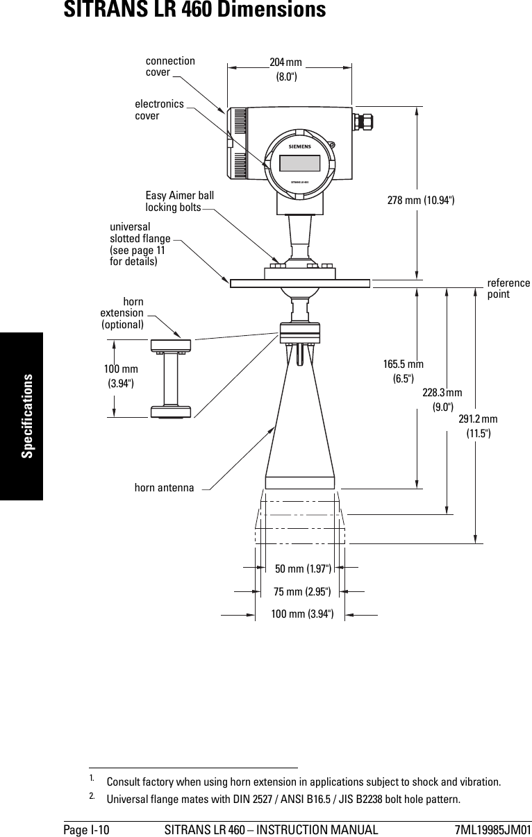
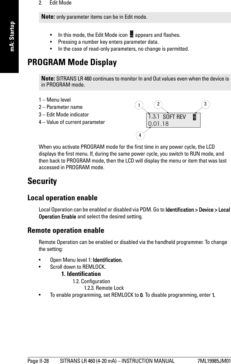
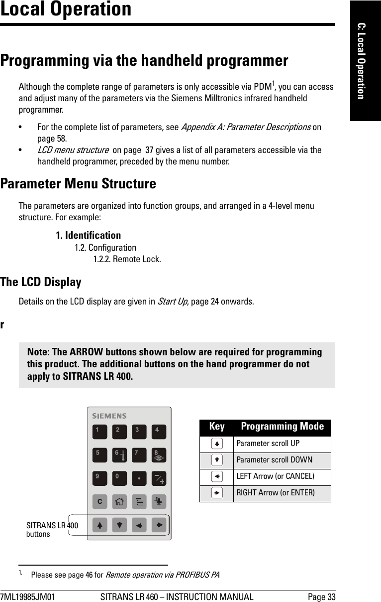
![7ML19985JM01 SITRANS LR 460 (4-20 mA) – INSTRUCTION MANUAL Page II-27mmmmmmA: StartupProgramming SITRANS LR 460The parameters that control the operation of the LR 460 are organized into function groups, and arranged in a 4-level menu structure that can be accessed either via the handheld programmer, or via PDM (see LCD menu structure on page 37).The handheld programmer1To activate PROGRAM mode, point the handheld programmer at the display (from a maximum distance of 600 mm [2 ft.]), and press the Mode key .The handheld programmer has two modes of operation:1. Navigation Mode• In this mode, the rightmost digit of the menu number flashes (the Edit Mode icon is not visible).• Press Up or Down arrow to change the menu number.• Press Right or Left arrow once to move to the next/previous menu level.• Press Right arrow again to switch from Navigation to Edit Mode2, or vice versa.1. See Programming via the handheld programmer on page 33 for more detail.Note: For Quick Access to parameters via the handheld programmer, press Mode key to activate PROGRAM mode, followed by Home key , then enter the menu number (see LCD menu structure on page 37 for details).2. When there is no further menu sub-level to access.displayhandheld programmermax. 600 mm (2 ft.)59C607 81 2 3 4numeric keysfunction Keys](https://usermanual.wiki/Siemens-Canada-Siemens-Milltronics-Process-Instruments/LR460/User-Guide-635569-Page-37.png)

![Page 36 SITRANS LR 460 – INSTRUCTION MANUAL 7ML19985JM01mmmmmC: Local Operation4. Press the Right ARROW key again, to accept the change and return to Navigation mode. Device calibrationOnly four settings are required for a Quick Setup: High Calibration Point, Low Calibration Point, High Level Point, and Low Level Point. (For an illustration, see Calibration on page 28.)2.3. Sensor Calibration:2.3.1. Sensor Units (default meters)2.3.2. Calibration Type.2.3.3. Low Calibration Pt.2.3.4. High Calibration Pt.2.3.5. Unit [Level] (default percent)2.3.6. Low Level Point2.3.7. High Level Point1. Go to Calibration Type and verify that "Dry" Calibration is selected.2. Go to Low Calibration Point and enter the new value (default units are meters).3. Go to High Calibration Point and enter the new value (default units are meters).4. Go to Low Level Point and enter the corresponding value in percent (default is 0).5. Go to High Level Point and enter the corresponding value in percent (default is 100).6. SITRANS LR 460 is now ready to operate.Values 0*"Dry" calibration1"Wet" calibration (not recommended for SITRANS LR 460)](https://usermanual.wiki/Siemens-Canada-Siemens-Milltronics-Process-Instruments/LR460/User-Guide-635569-Page-46.png)
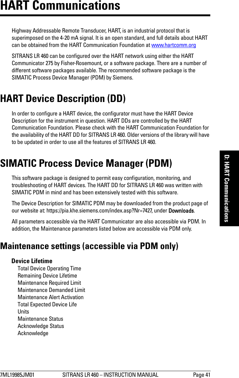
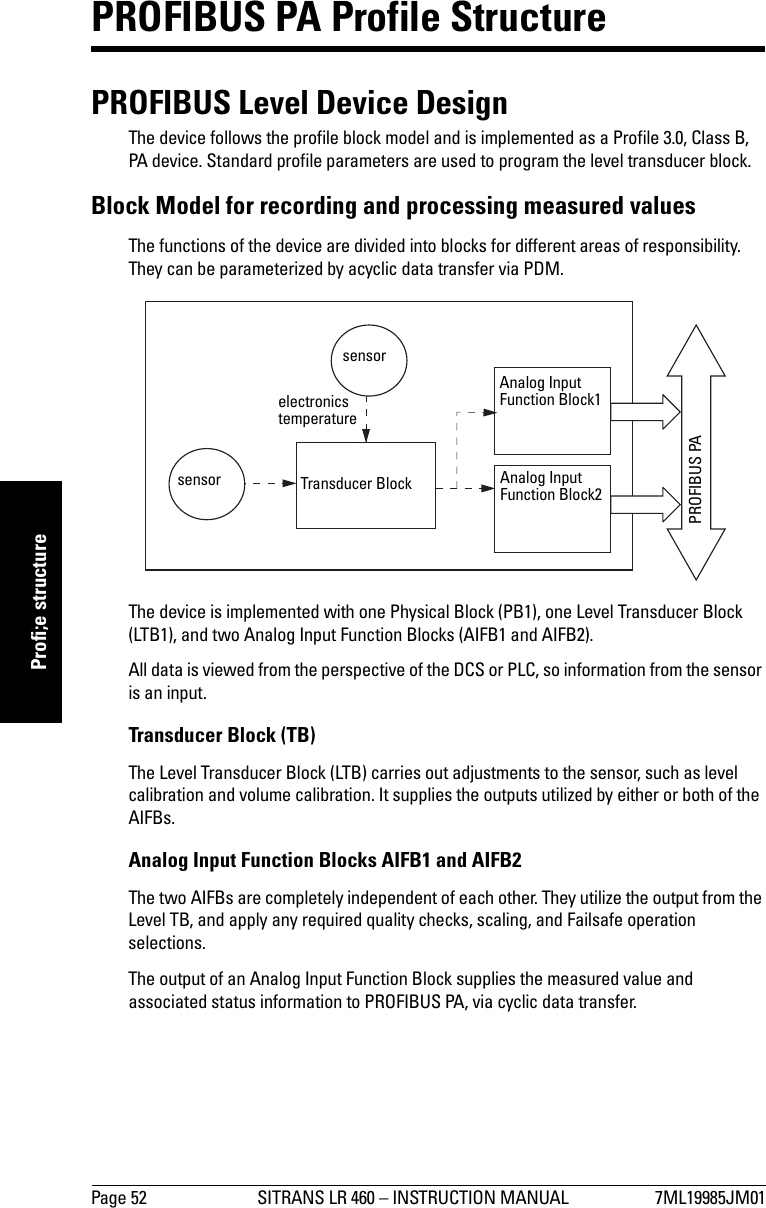
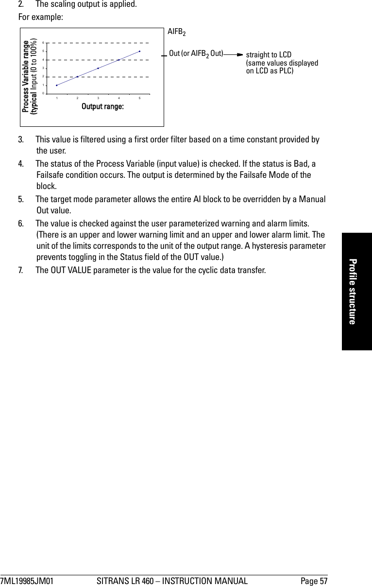
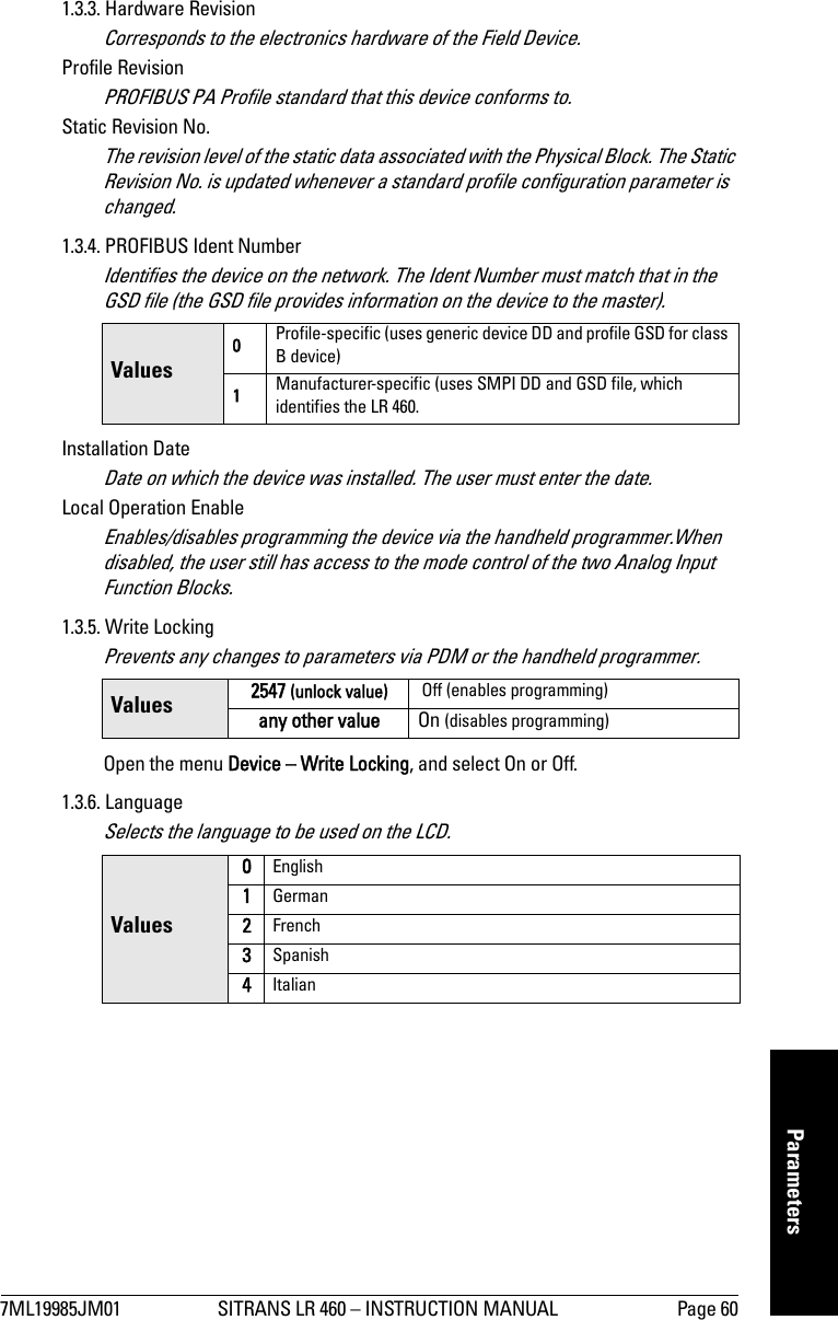
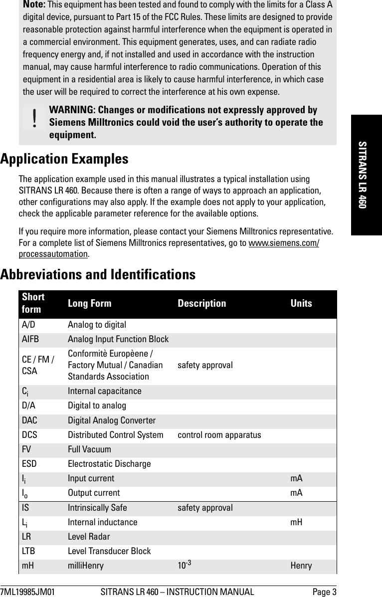
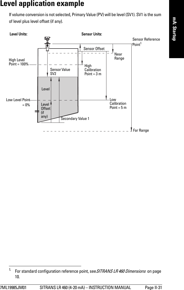
(Analog Input)AIFB1Secondary Value 1 [Level](Level Units)Secondary Value 2 [Distance 1](Sensor Units)Sensor OffsetLevel OffsetHigh Calibration PointHigh Level Point Low Calibration Point Low Level PointCalibration TypeLinearization TypeSecondary Value 2[Distance 2](Level Units)Sensor Level unit conversionPVSV1SV2SV3AIFB2(Analog Input)](https://usermanual.wiki/Siemens-Canada-Siemens-Milltronics-Process-Instruments/LR460/User-Guide-635569-Page-63.png)