Siemens Canada Siemens Milltronics Process Instruments LR460 SITRANS LR 460 TANK LEVEL PROBING RADAR User Manual JM01 LR460
Siemens Canada Ltd. - Siemens Milltronics Process Instruments SITRANS LR 460 TANK LEVEL PROBING RADAR JM01 LR460
USERS MANUAL

Instruction Manual February 2006
LR 460
sitrans
Draft Manual
02/13/2006

© Siemens Milltronics Process Instruments Inc. 2006
Safety Guidelines: Warning notices must be observed to ensure personal safety as well as that of
others, and to protect the product and the connected equipment. These warning notices are
accompanied by a clarification of the level of caution to be observed.
Qualified Personnel: This device/system may only be set up and operated in conjunction with this
manual. Qualified personnel are only authorized to install and operate this equipment in accordance with
established safety practices and standards.
Unit Repair and Excluded Liability:
• The user is responsible for all changes and repairs made to the device by the user or the user’s
agent.
• All new components are to be provided by Siemens Milltronics Process Instruments Inc.
• Restrict repair to faulty components only.
• Do not reuse faulty components.
Warning: This product can only function properly and safely if it is correctly transported, stored,
installed, set up, operated, and maintained.
Note: Always use product in accordance with specifications.
Copyright Siemens Milltronics Process
Instruments Inc. 2006. All Rights Reserved
Disclaimer of Liability
This document is available in bound version and in
electronic version. We encourage users to purchase
authorized bound manuals, or to view electronic versions
as designed and authored by Siemens Milltronics Process
Instruments Inc. Siemens Milltronics Process Instruments
Inc. will not be responsible for the contents of partial or
whole reproductions of either bound or electronic
versions.
While we have verified the contents of this
manual for agreement with the
instrumentation described, variations
remain possible. Thus we cannot
guarantee full agreement. The contents of
this manual are regularly reviewed and
corrections are included in subsequent
editions. We welcome all suggestions for
improvement.
Technical data subject to change.
MILLTRONICS®is a registered trademark of Siemens Milltronics Process Instruments Inc.
Contact SMPI Technical Publications at the following address:
Technical Publications
Siemens Milltronics Process Instruments Inc.
1954 Technology Drive, P.O. Box 4225
Peterborough, Ontario, Canada, K9J 7B1
Email: techpubs.smpi@siemens.com
• For a selection of Siemens Milltronics level measurement manuals, go to:
www. siemens.com/processautomation. Under Process Instrumentation, select
Level
Measurement
and then go to the manual archive listed under the product family.
• For a selection of Siemens Milltronics weighing manuals, go to:
www. siemens.com/processautomation. Under Weighing Technology, select
Continuous
Weighing Systems
and then go to the manual archive listed under the product family.

i
mmmmm
Table of Contents
Table of Contents
Table of Contents .................................................................................................................i
Safety Notes .............................................................................................................................................1
Safety marking symbols ..............................................................................................................1
The Manual ...............................................................................................................................................2
Application Examples ...................................................................................................................3
Abbreviations and Identifications .............................................................................................3
Programming ............................................................................................................................................4
Approvals and Certificates .........................................................................................................4
Part I: SITRANS LR 460 (all versions) .................................. 1
SITRANS LR 460 ...................................................................................................................2
System Implementation .........................................................................................................................3
Typical PLC/mA configuration with HART............................................................................. 3
Typical PLC/mA configuration with PROFIBUS PA............................................................. 3
............................................................................................................................................................3
Specifications ......................................................................................................................5
SITRANS LR 460 .............................................................................................................................5
Power............................................................................................................................................. 5
Performance................................................................................................................................. 5
Interface ........................................................................................................................................ 6
Programmer (infrared keypad) ................................................................................................ 6
Mechanical................................................................................................................................... 7
Environmental .............................................................................................................................. 8
Process.......................................................................................................................................... 8
Communication............................................................................................................................ 8
Approvals ...................................................................................................................................... 9
(verify against device nameplate)........................................................................................... 9
SITRANS LR 460 Dimensions ........................................................................................................... 10
Flange Dimensions ......................................................................................................................11
Installation ......................................................................................................................... 13
Mounting Location ................................................................................................................................13
Beam Width ..................................................................................................................................15
Installation in Mounting Nozzle ...............................................................................................15
Easy Aimer Installation ..............................................................................................................16
Easy Aimer Positioning ..............................................................................................................16
Wiring .................................................................................................................................. 19
Connecting SITRANS LR 460 ..............................................................................................................19
AC version................................................................................................................................... 20
DC version................................................................................................................................... 20

ii
mmmmm
Table of Cotents
Hazardous area installations .............................................................................................................22
Product Nameplate .....................................................................................................................22
Instructions specific to hazardous area installations ........................................................22
EU Equivalency .......................................................................................................................... 23
Part II: SITRANS LR 460 4-20 mA version ......................... 25
4-20 mA Start Up ...............................................................................................................26
Startup Display (RUN mode) ................................................................................ 26
Programming SITRANS LR 460.............................................................................................. 27
The handheld programmer .......................................................................................................27
PROGRAM Mode Display .........................................................................................................28
Security ..........................................................................................................................................28
Local operation enable............................................................................................................ 28
Remote operation enable........................................................................................................ 28
Write locking .............................................................................................................................. 29
How to do a Master Reset ........................................................................................................29
Fault Reset .................................................................................................................................. 29
Quick Setup .............................................................................................................................................29
Activating SITRANS LR 460 ......................................................................................................29
Performing calibration via PDM............................................................................................ 29
Using Auto False Echo Suppression .................................................................................... 30
Level application example ...................................................................................................................31
Local Operation .................................................................................................................33
Programming via the handheld programmer .................................................................................33
Parameter Menu Structure .......................................................................................................33
The LCD Display......................................................................................................................... 33
r...................................................................................................................................................... 33
Using the handheld programmer .......................................................................................... 34
Security ..........................................................................................................................................34
Local operation enable............................................................................................................ 34
Write locking .............................................................................................................................. 34
Remote operation enable........................................................................................................ 34
How to do a Master Reset ........................................................................................................35
Master Reset.............................................................................................................................. 35
Individual Parameter Reset ................................................................................................... 35
Fault Reset .................................................................................................................................. 35
Device calibration ..................................................................................................................... 36

iii
mmmmm
Table of Contents
LCD menu structure ..........................................................................................................37
HART Communications ...................................................................................................41
HART Device Description (DD) ...........................................................................................................41
SIMATIC Process Device Manager (PDM) .....................................................................................41
Maintenance settings (accessible via PDM only) ..............................................................41
Supported HART Commands: ............................................................................................................42
Universal and Common Practice Commands .......................................................................43
Device Specific Commands ......................................................................................................43
Part III: SITRANS LR 460 PROFIBUS PA version.............. 45
Remote operation via PROFIBUS PA .............................................................................46
SIMATIC PDM ........................................................................................................................................46
Device Description ................................................................................................................................46
Configuration ..........................................................................................................................................47
The GSD file ............................................................................................................................................47
Setting the PROFIBUS address .........................................................................................................47
Bus Termination .....................................................................................................................................47
Power Demands ....................................................................................................................................47
Cyclic versus Acyclic Data ..................................................................................................................47
Cyclic Data ....................................................................................................................................48
Status Byte .............................................................................................................................................48
Diagnostics .............................................................................................................................................49
Diagnosis reply (applies only to cyclic masters) .................................................................49
Acyclic Diagnostics .....................................................................................................................50
Acyclic Extended Diagnostics (General Fault Codes) ........................................................51
Acyclic Data ............................................................................................................................................51
Configuration Example ...............................................................................................................51
PROFIBUS PA Profile Structure .....................................................................................52
PROFIBUS Level Device Design ........................................................................................................52
Block Model for recording and processing measured values ...................................... 52
Description of the blocks ...........................................................................................................53
Transducer block function groups........................................................................................ 53
Analog Input Function Blocks 1 and 2.................................................................................. 55
Appendix A: Parameter Descriptions ...........................................................................58
Identification..........................................................................................................................................58
Operation Unit ............................................................................................................................58
Configuration ..............................................................................................................................58
Device .......................................................................................................................................... 59
Statistics...................................................................................................................................... 61
Input .......................................................................................................................................................61
Static Revision Number ...........................................................................................................61
Class .............................................................................................................................................61
Reset Filter ..................................................................................................................................61
Standard Setup.......................................................................................................................... 61
Sensor Calibration .................................................................................................................... 63

iv
mmmmm
Table of Cotents
Measuring Limits....................................................................................................................... 64
Detailed Setup ........................................................................................................................... 65
Output ....................................................................................................................................................72
AIFB1............................................................................................................................................ 72
AIFB2............................................................................................................................................ 74
Device Certification ..................................................................................................................75
Maintenance settings ........................................................................................................................75
Remaining Device Lifetime ..................................................................................................... 75
Remaining Sensor Lifetime..................................................................................................... 75
Service Interval.......................................................................................................................... 75
Calibration Interval.................................................................................................................... 76
Condensed Status Setup ..................................................................................................................76
Condensed Status Mode .........................................................................................................76
Appendix B: Technical Reference .................................................................................82
Principles of Operation ........................................................................................................................82
Measurement Response .....................................................................................................................82
Echo Lock ................................................................................................................................................83
Loss of Echo (LOE) .................................................................................................................................83
LOE Timer ......................................................................................................................................84
Failsafe Mode ...............................................................................................................................84
False Echoes ...........................................................................................................................................84
Near Range (Blanking) ..............................................................................................................84
Auto False-Echo Suppression ..................................................................................................84
Maximum Process Temperature Chart ............................................................................................86
..........................................................................................................................................................86
Appendix C: Troubleshooting .........................................................................................87
General Fault Codes .............................................................................................................................88
Appendix D: Maintenance ..............................................................................................92
Unit Repair and Excluded Liability ....................................................................................................92
Appendix E: Software Revision History ........................................................................93
Glossary ..............................................................................................................................94
Index ....................................................................................................................................98
7ML19985JM01 SITRANS LR 460 – INSTRUCTION MANUAL Page 1
mmmmm
SITRANS LR 460
Safety Notes
Special attention must be paid to warnings and notes highlighted from the rest of the text
by grey boxes.
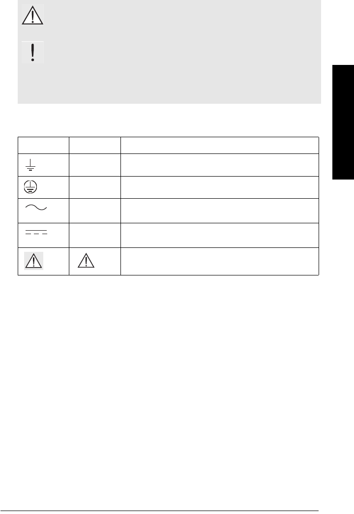
Safety marking symbols
WARNING: relates to a caution symbol on the product, and means
that failure to observe the necessary precautions can result in death,
serious injury, and/or considerable material damage.
WARNING: means that failure to observe the necessary precautions
can result in death, serious injury, and/or considerable material
damage.
Note: means important information about the product or that part of the operating
manual.
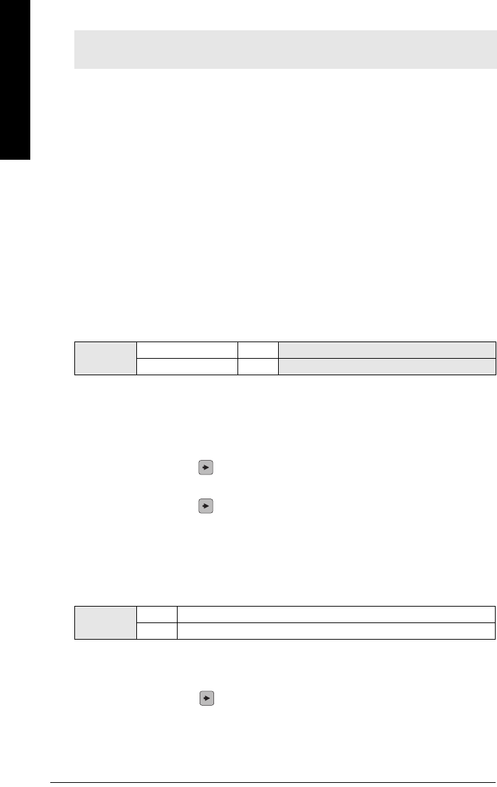
In manual: On product: Description
Earth (ground) Terminal
Protective Conductor Terminal
Alternating Current
Direct Current
(Label on product: yellow background.) WARNING: refer
to accompanying documents (manual) for details.

Page 2 SITRANS LR 460 – INSTRUCTION MANUAL 7ML19985JM01
mmmmm
SITRANS LR 460
The Manual
This manual will help you set up your SITRANS LR 460 for optimum performance.
SITRANS LR 460 is available in two versions (HART or PROFIBUS PA), and the manual is
in three parts:
Part I: information common to both versions
• introduction to LR 460
• specifications
• installation
•wiring
Part II: SITRANS LR 460 4-20 mA version
• 4-20 mA Quick Setup
• local operation using handheld programmer
• LCD menu charts
• HART communications
Part III: SITRANS LR 460 PROFIBUS PA version:
• PROFIBUS PA Quick Setup
• remote operation
•PA profile
•PA Data Maps
Appendices provide further information common to both models:
•
Appendix A: Parameter Descriptions
•
Appendix B: Technical Reference
•
Appendix C: Troubleshooting
•
Appendix D: Maintenance
•
Appendix E: Software Revision History
We always welcome suggestions and comments about manual content, design, and
accessibility. Please direct your comments to techpubs.smpi@siemens.com.
For other Siemens Milltronics level measurement manuals, go to:
www.siemens.com/level, and look under Level Measurement.
Notes:
• Please follow the installation and operating procedures for a quick, trouble-free
installation and to ensure the maximum accuracy and reliability of your SITRANS LR 460.
This manual applies to the SITRANS LR 460 only.

7ML19985JM01 SITRANS LR 460 – INSTRUCTION MANUAL Page 3
mmmmm
SITRANS LR 460
Application Examples
The application example used in this manual illustrates a typical installation using
SITRANS LR 460. Because there is often a range of ways to approach an application,
other configurations may also apply. If the example does not apply to your application,
check the applicable parameter reference for the available options.
If you require more information, please contact your Siemens Milltronics representative.
For a complete list of Siemens Milltronics representatives, go to www.siemens.com/
processautomation.
Abbreviations and Identifications
Note: This equipment has been tested and found to comply with the limits for a Class A
digital device, pursuant to Part 15 of the FCC Rules. These limits are designed to provide
reasonable protection against harmful interference when the equipment is operated in
a commercial environment. This equipment generates, uses, and can radiate radio
frequency energy and, if not installed and used in accordance with the instruction
manual, may cause harmful interference to radio communications. Operation of this
equipment in a residential area is likely to cause harmful interference, in which case
the user will be required to correct the interference at his own expense.
WARNING: Changes or modifications not expressly approved by
Siemens Milltronics could void the user’s authority to operate the
equipment.
Short
form Long Form Description Units
A/D Analog to digital
AIFB Analog Input Function Block
CE / FM /
CSA
Conformitè Europèene /
Factory Mutual / Canadian
Standards Association
safety approval
CiInternal capacitance
D/A Digital to analog
DAC Digital Analog Converter
DCS Distributed Control System control room apparatus
FV Full Vacuum
ESD Electrostatic Discharge
IiInput current mA
IoOutput current mA
IS Intrinsically Safe safety approval
LiInternal inductance mH
LR Level Radar
LTB Level Transducer Block
mH milliHenry 10-3 Henry

Page 4 SITRANS LR 460 – INSTRUCTION MANUAL 7ML19985JM01
mmmmm
SITRANS LR 460
Programming
SITRANS LR 460 carries out its level measurement function according to the set of built-in
parameter tables. You can make parameter changes via the Siemens Milltronics
handheld programmer, a PC running SIMATIC PDM or a HART handheld communicator.
Approvals and Certificates
µF microFarad 10-6 Farad
µsmicrosecond 10-6 Second
PA Process Automation
(PROFIBUS)
PDM Process Device Manager
(SIMATIC)
PED Pressure Equipment
Directive safety approval
pF pico Farads 10-12 Farad
ppm parts per million
PSIA pounds/square inch absolute
PV Primary Value1measured value
RH relative humidity
SCFM standard cubic feet/minute
SELV Safety extra low voltage
SV Secondary Value1equivalent value
TB Transducer Block
TV Transmitter Variable
TVT Time Varying Threshold sensitivity threshold
UiInput voltage V
UoOutput voltage V
1. The output from the Level Transducer Block can be called the Primary Value (or
Secondary Value). When it becomes the input to the AIFB, it is called the
Process Variable.
Note: Please see
Approvals
on page 9.
Short
form Long Form Description Units
(cont’d)

7ML19985JM01 SITRANS LR 460 – INSTRUCTION MANUAL Page I-1
mmmmm
SITRANS LR 460
Part I: SITRANS LR 460
(all versions)
Page I- 2 SITRANS LR 460 – INSTRUCTION MANUAL 7ML19985JM01
mmmmm
SITRANS LR 460
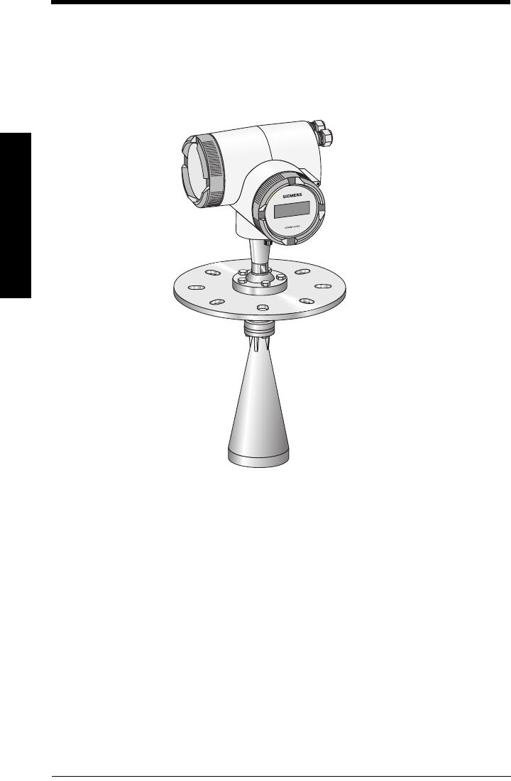
SITRANS LR 460
SITRANS LR 460 is a long-range FMCW radar level transmitter for level measurement of
solids. It can be used in high pressure applications or applications requiring gas safety
approvals. The Easy Aimer design makes it easy to set up the device even in conditions of
extreme dust. The narrow antenna beam creates a sharp emission cone, which makes the
LR 460 quite insensitive to vessel interferences.
7ML19985JM01 SITRANS LR 460 – INSTRUCTION MANUAL Page I-3
mmmmm
SITRANS LR 460
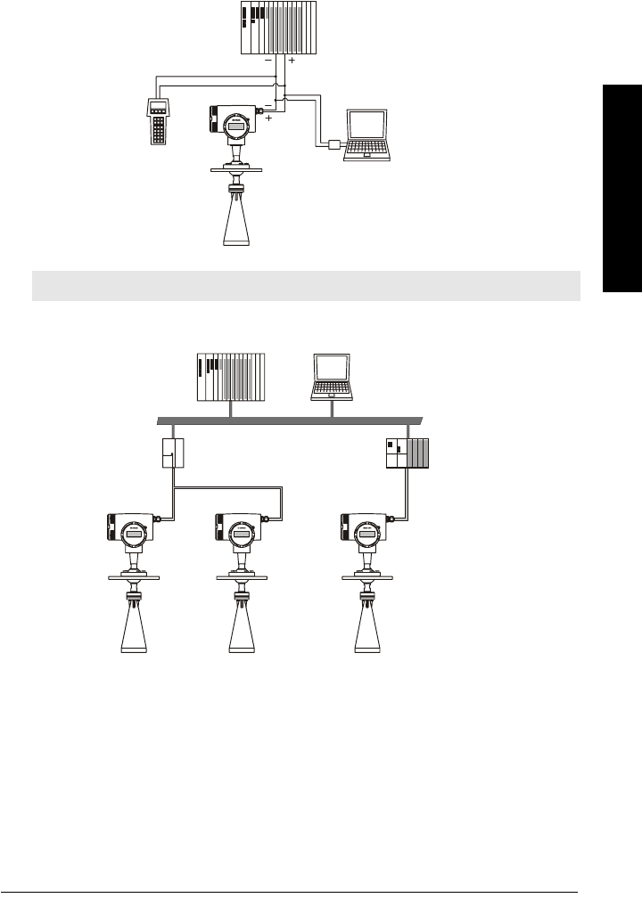
System Implementation
SITRANS LR 460 supports HART communication protocol, and SIMATIC PDM software.
Typical PLC/mA configuration with HART
Typical PLC/mA configuration with PROFIBUS PA
Note: A 250 ohm loop resistor may be required, depending on PLC input resistance.
SITRANS LR 400
PLC with mA
input card
HART
HART
Communicator 275
SITRANS LR 460
PC/laptop with HART
modem running PDM
SITRANS LR 400 SITRANS LR 400 SITRANS LR 400
Class 1
Master
DP/PA
Coupler PROFIBUS PA
HART
ET200
Class 2
Master
SITRANS
LR 460
SITRANS
LR 460
SITRANS
LR 460
PLC PDM

Page I- 4 SITRANS LR 460 – INSTRUCTION MANUAL 7ML19985JM01
mmmmm
SITRANS LR 460

7ML19985JM01 SITRANS LR 460 – INSTRUCTION MANUAL PageI-5
mmmmm
Specifications
Specifications
SITRANS LR 460
Power
Power Supply (HART)
• 100 to 230 V AC, ±15%, 50/60 Hz, 6 W (12VA)
• 24 V DC, +25/-20%, 6 W
• Power failure: bridge of at least 1 mains period (> 20 ms)
• Fuse (AC ) SI1 Fast acting ceramic, 4 x 20 mm, 1 A, 250 V AC
SI2 Slow-Blow, 4 x 20 mm, 0.63 A, 250 V AC
• Fuse (DC ) SI1 Fast acting ceramic, 4 x 20 mm, 2 A, 250 V AC
SI2 Slow-Blow, 4 x 20 mm, 0.63 A, 250 V AC
Power Supply (PROFIBUS PA)
Performance
Reference operating conditions according to IEC 60770-1
• ambient temperature +15 to +25 oC
• humidity 45 to 75 % relative humidity
• ambient pressure 860 to 1060 mbar (12.47 to 15.37 psi)
Measurement Accuracy (measured in accordance with IEC 60770-1)
• non-linearity (accuracy) greater of 25 mm (1”) or 0.25% of span (including
hysteresis and non-repeatability)
• non-repeatability 10 mm (0.4”) [included in non-linearity specification]
• deadband (resolution) 10 mm (0.4”) [included in non-linearity specification]
• hysteresis error 0 mm
Analog Output Accuracy (measured in accordance with IEC 60770-1)
• non-linearity (accuracy) 0.100% of span (including hysteresis and repeatability)
• non-repeatability 0.030% of span (included in non-linearity specification)
• deadband (resolution) 0.030% of span [included in non-linearity specification]
• hysteresis error 0%
Frequency 25 GHz nominal
Measurement range 0.35 to 70 m (1.15 to 229.66 ft)1
Note: Siemens Milltronics makes every attempt to ensure the accuracy of these
specifications, but reserves the right to change them at any time.
1. Minimum range: 0.35 m (1.15 ft) from bottom of flange.

Page I-6 SITRANS LR 460 – INSTRUCTION MANUAL 7ML19985JM01
mmmmm
Specifications
Long-term stability ≤ ± 1 mm/year
Update time at 4mA mA output and loop display is updated once per
second
Beam angle 3" horn: 11° at –3 dB boundary
4" horn: 8° at –3 dB boundary
Memory
• non-volatile EEPROM
• no battery required
Interface
Analog output (Not applicable to PROFIBUS PA option)
• signal range 4 to 20 mA
upper limit 20 to 22.5 mA adjustable
• fail signal 3.6 mA; 22 mA; 24 mA or last value
• load Max. 600 Ω; for HART1 communication min. 230 Ω
Digital output
• function Configurable as a device status or limit value (level,
volume, mass)
• signal type Relay, either NCC or NOC function, max. 50 V DC,
max. 200 mA, rating max. 5 W.
Self-resetting fuse, Ri=9 Ω
Electrical isolation Outputs electrically isolated from the power supply and
from each other
Display
• LCD two lines of 16 characters each, configurable for the
following displays:
level, volume, mass, amplitude, digital output,
temperature, validity, signal-to-noise ratio
Programmer (infrared keypad)
Siemens Milltronics infrared IS (Intrinsically Safe) handheld programmer for hazardous
and all other locations (battery is non-replaceable)
• approval: ATEX II 1 G EEx ia IIC T4, certificate SIRA 01ATEX2147
CSA and FM Class I, Div. 1, Gr. A, B, C, D T6 @ max.
ambient temperature of 40 °C (104 °F)
1. HART® is a registered trademark of HART Communication Foundation.

7ML19985JM01 SITRANS LR 460 – INSTRUCTION MANUAL PageI-7
mmmmm
Specifications
• ambient temperature: −20 to 40 °C (−5 to 104 °F)
• interface: proprietary infrared pulse signal
• power: 3 V lithium battery
• weight: 150 g (0.3 lb)
•color: black
Mechanical
Wetted parts (in contact
with the process) Stainless steel flange and horn; PTFE emitter
Process Connection
• universal flanges 2"/50 mm, 3"/80 mm, 4"/100 mm, 6"/150 mm (See page 11
for flange dimensions.)
Pressure (vessel) 0.5 bar (7.25 psi) maximum
Horn
• horn diameters 3" (80 mm); 4" (100 mm)
• optional extensions 4" or 8" (100 or 200 mm)
500 and 1000 mm available for non-purged versions
only
Weight
• Weight of instrument and flange
Enclosure
• construction Die-cast aluminum, painted (polyester powder-coated)
• conduit 2 x M20
or 2 x ½” NPT (option)
• ingress protection Type 4X/NEMA 4X, Type 6/NEMA 6, IP671
Process Connection Weight
Universal, 3" / 80 mm flange with 3" horn 6.1 kg (13.4 lbs)
Universal, 4" / 100 mm flange with 4" horn 6.8 kg (15.0 lbs)
Universal, 6" / 160 mm flange with 4"horn TBA
1. Use only approved, suitable sized hubs for watertight applications.

Page I-8 SITRANS LR 460 – INSTRUCTION MANUAL 7ML19985JM01
mmmmm
Specifications
Environmental1
• location indoor/outdoor
• altitude 2000 m (6562 ft) max
• ambient temperature2-40 to 65 °C (-40 to 149 °F)
• relative humidity suitable for outdoor (Type / NEMA 4X, 6/ IP67)
• installation category II
• pollution degree 4
• Perm. ambient -40 to 65 °C (-40 to 149 °F) (non-hazardous version)
temperature3LCD: -10 to 55 °C (14 to 131 °F)
Observe the temperature classes in hazardous areas!
Process
• Process temperature -40 to 200 °C (-40 to 392 °F)
[-40 to 250 °C (-40 to 418 °F) option]
• Pressure (vessel) 0.5 bar (7.25 psi) maximum
Communication
• Communication: HART
Load 230 to 600 Ω, 230 to 500 Ω when connecting a coupling
module
Line two-wire shielded: ≤ 3000 m
multi-wire shielded: ≤ 1500 m
Protocol HART, Version 5.1
• Communication: PROFIBUS PA
Protocol Layer 1 and 2 PROFIBUS PA,
technology: IEC 61158-2, slave-functionality
Device Class A
Device Profile 3.0
• Software for PC/Laptop Windows 95/98/2000/XP or NT 4.0
SIMATIC® PDM
1. See Process/Ambient de-rating curves in Appendix III.
2. -20 °C (-4 °F) temperature rating available on SITRANS LR 460 with ATEX rating.
WARNING: Materials of construction are chosen based on their chemical
compatibility (or inertness) for general purposes. For exposure to specific
environments, check with chemical compatibility charts before installing.

7ML19985JM01 SITRANS LR 460 – INSTRUCTION MANUAL PageI-9
mmmmm
Specifications
Approvals
(verify against device nameplate)
• Hazardous areas FM/CSA Class II, Div. 1, Groups E,F and G, Class III
ATEX II 1/2 D T6
• General CSAus/c, FM, CE
• Radio FCC, Industry Canada, European Radio (R&TTE)
Page I-10 SITRANS LR 460 – INSTRUCTION MANUAL 7ML19985JM01
mmmmm
Specifications
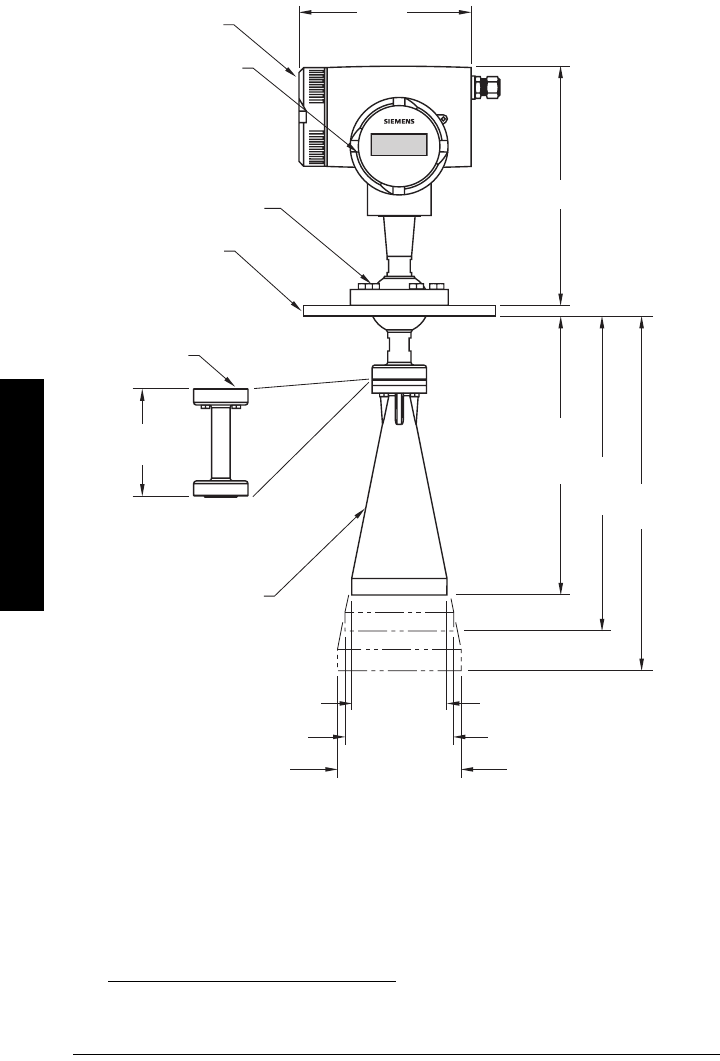
SITRANS LR 460 Dimensions
1 2
1. Consult factory when using horn extension in applications subject to shock and vibration.
2. Universal flange mates with DIN 2527 / ANSI B16.5 / JIS B2238 bolt hole pattern.
SITRANS LR 400
204 mm
(8.0")
278 mm (10.94")
electronics
cover
connection
cover
universal
slotted flange
(see page 11
for details)
horn antenna
50 mm (1.97")
75 mm (2.95")
228.3 mm
(9.0")
165.5 mm
(6.5")
291.2 mm
(11.5")
100 mm (3.94")
100 mm
(3.94")
horn
extension
(optional)
Easy Aimer ball
locking bolts
reference
point
7ML19985JM01 SITRANS LR 460 – INSTRUCTION MANUAL PageI-11
mmmmm
Specifications
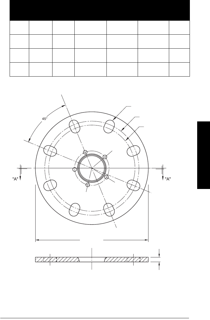
Flange Dimensions
Universal Slotted Flange Diagram
Pipe
Size
Flange
O.D.
Thick-
ness (s)
Bolt Hole
Circle Max Ø
Bolt Hole
Circle Min Ø
Bolt Hole
radius
No. of
Slotted
Holes
2" or
50 mm
7.87"
(200 mm)
0.38"
(9.65 mm)
4.92"
(125 mm)
4.72"
(120 mm)
0.38"
(9.5 mm)
4
3" or
80 mm
7.87"
(200 mm)
0.38"
(9.65 mm)
6.30"
(160 mm)
5.91"
(150 mm)
0.38"
(9.5 mm)
8
4" or
100 mm
9.00"
(229 mm)
0.38"
(9.65 mm)
7.52"
(191 mm)
6.89"
(175 mm)
0.38"
(9.5 mm)
8
6" or
150 mm
11.22"
(285 mm)
0.38"
(9.65 mm)
9.53"
(242 mm)
9.45"
(240 mm)
0.45"
(11.5 mm)
8
flange O.D.
bolt hole circle
min. diameter
number of slotted
bolt holes
section A-A
thickness
bolt hole circle
max. diameter
Page I-12 SITRANS LR 460 – INSTRUCTION MANUAL 7ML19985JM01
mmmmm
Specifications
Purged LR 460 version
1
Requirements for effective cleaning
Recommended pressure 90 to 110 psi
Recommended inlet flow 10 SCFM 1
Note: Short bursts of high pressure periodically are more effective for purging than
continuous low pressure.
1. SCFM: standard cubic feet/minute referenced to 14.7 psia, 68°F and 36% relative humidity (RH)
alignment markings
purged process connection with
factory-installed 1/2" NPT plug

7ML19985JM01 SITRANS LR 460 – INSTRUCTION MANUAL Page 13
mmmmm
Installation
Installation
Mounting Location
Recommendations
• Provide easy access for viewing display and programming via handheld
programmer.
• Provide an environment suitable to the housing rating and materials of construction.
• Mount the unit more than 1 meter away from vessel walls, pipes and other
assemblies as well as the filling stream, which could cause reflective interference.
• Align the antenna so that the radar cone intersects the surface of the measuring
medium vertically if possible.
WARNINGS:
• SITRANS LR 460 is to be used only in the manner outlined in this
manual, otherwise protection provided by the equipment may be
impaired.
• Installation shall only be performed by qualified personnel and in
accordance with local governing regulations.
• Improper installation may result in loss of process pressure
Notes:
• Installation must be according to ETSI EN 302372.
• Refer to device nameplate for approval information.
• For Type 4X/NEMA 4X, Type 6/NEMA 6, IP67 type of protection use only approved,
suitable sized hubs for watertight applications.
• Observe all maximum permissible ambient and process temperatures. Refer to
Maximum Process Temperature Chart
on page 86.
• Provide a warning sign and/or touch guard if the surface of the measuring
instrument can become hotter than 70 °C (158 °F) in use.
Page 14 SITRANS LR 460 – INSTRUCTION MANUAL 7ML19985JM01
mmmmm
Installation
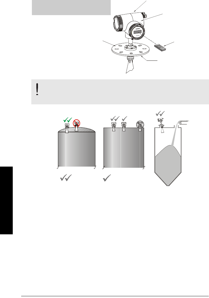
Precautions
• Do not mount in direct sunlight without the use of a sun shield.
• Avoid interference to emission cone from obstructions or from fill path.
• Avoid central locations on vessel.
WARNING: For vessels with conical or parabolic tops, avoid mounting
the unit at the center. The concavity of the top can focus echoes into the
centre, giving false readings.
Flat
P a ra b o lic
SITRA
N
S
L
R 40
0
Parabolic or Conical Flat
is preferred
location
is acceptable
location
ambient temperature
65 °C (149 °F) max.
internal enclosure
temperature
handheld
programmer
process temperature
Warning: Internal temperature
must not exceed 85 °C (185 °F)!
flange
temperature
7ML19985JM01 SITRANS LR 460 – INSTRUCTION MANUAL Page 15
mmmmm
Installation
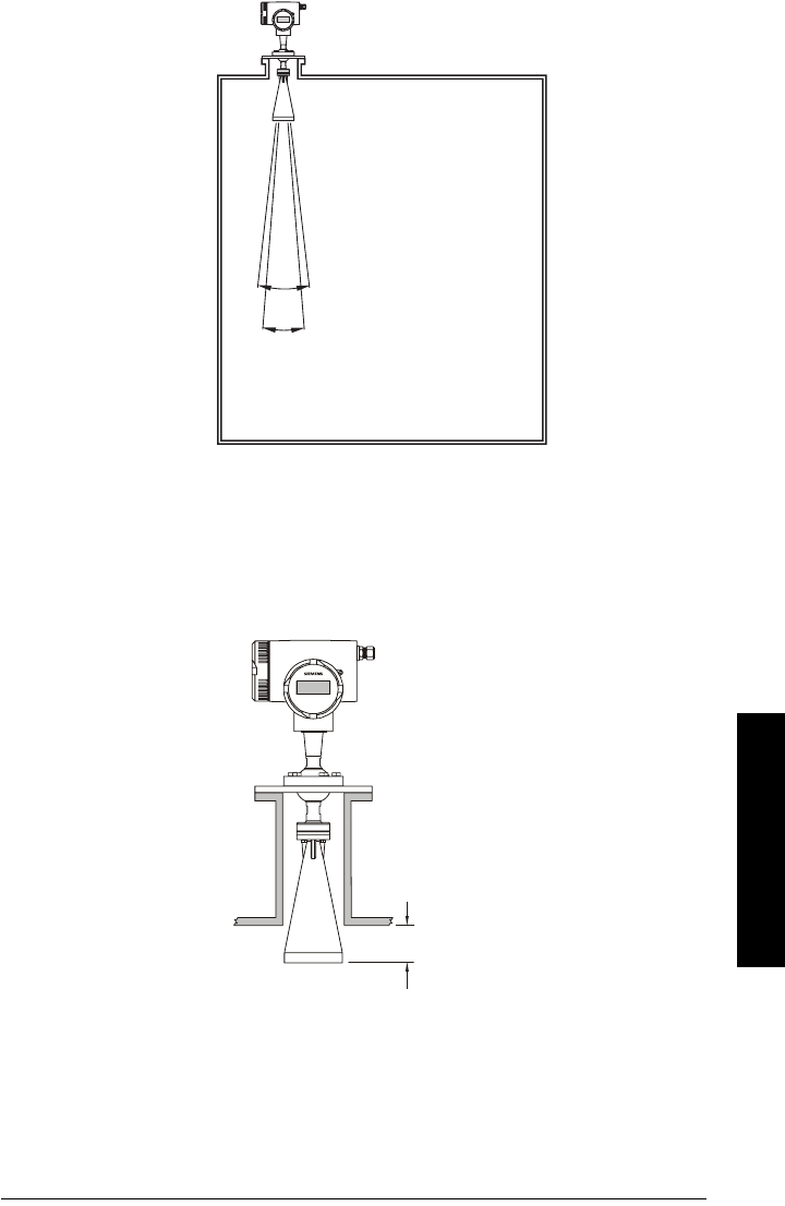
Beam Width
Installation in Mounting Nozzle
The bottom edge of the antenna must project into the vessel to avoid reflective
interference at the wall of the nozzle. If the process nozzle diameter is greater than 6", the
antenna does not need to project beyond the nozzle unless the emission cone touches
the nozzle wall.
Keep the emission cone
free of obstructions.
3" horn
4" horn
11°
8°
SITRANS LR 400
10 mm
GRAPHIC TO
BE UPDATED
Page 16 SITRANS LR 460 – INSTRUCTION MANUAL 7ML19985JM01
mmmmm
Installation
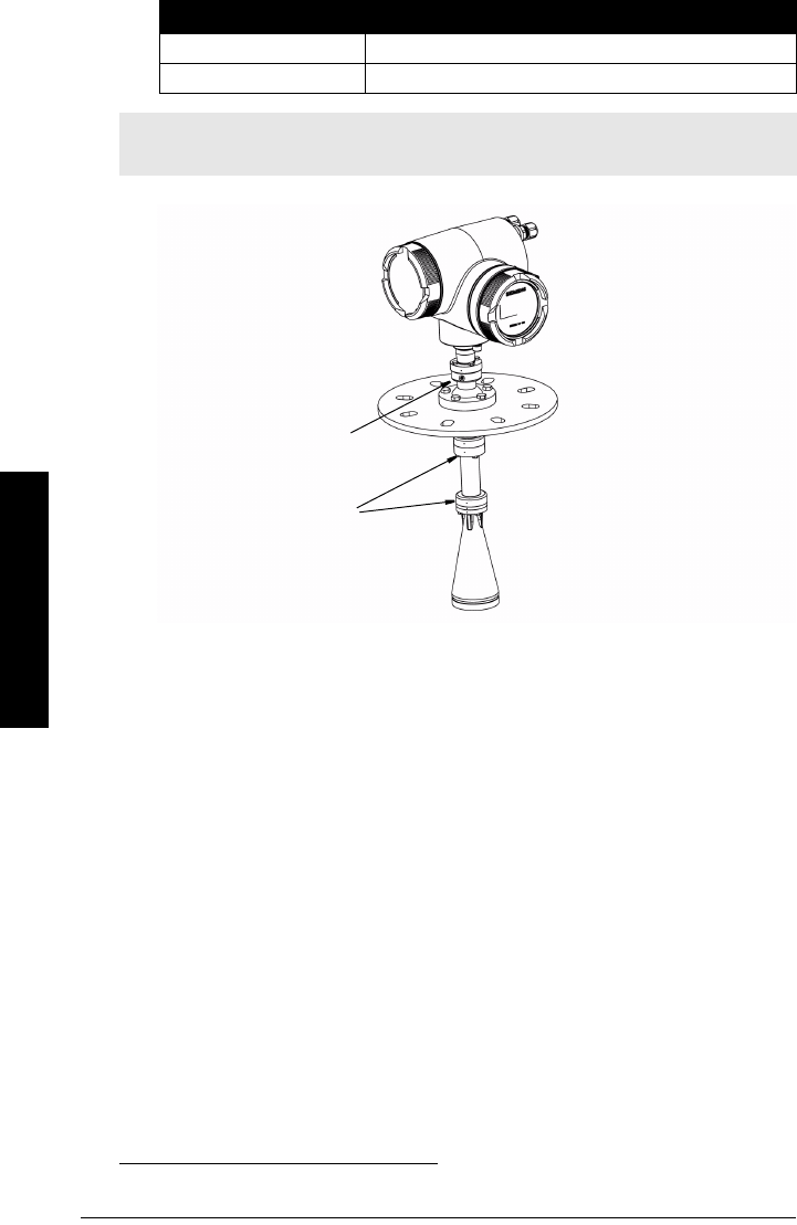
Easy Aimer Installation
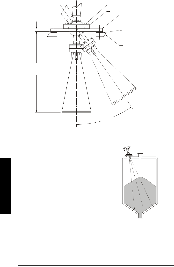
Easy Aimer Positioning
• Direct SITRANS LR 460 so the horn antenna
is pointed at an angle to the filling level as
shown.
• Loosen the Easy Aimer ball locking bolts and
position the LR 460.
• Tighten bolts to secure the device.
top clamping plate (upper socket)
bottom clamping plate (lower socket
)
customer gasket as required
[recommended thickness 1.5 to
1.8 mm (0.06 to 0.07")]
customer mounting plate, as
required
ø 4" (102 mm) min., central
opening
30°
max.
2" horn: 6.5" (165.5 mm)
3" horn: 9.0" (228.3 mm)
4" horn: 11.5" (291.2 mm)
0.38"
(10 mm)
Easy Aimer ball locking bolts
S
IT
RA
NS LR
400
Easy Aimer

7ML19985JM01 SITRANS LR 460 – INSTRUCTION MANUAL Page 17
mmmmm
Installation
Notes

Page 18 SITRANS LR 460 – INSTRUCTION MANUAL 7ML19985JM01
mmmmm
Installation

7ML19985JM01SITRANS LR 460 – INSTRUCTION MANUAL Page 19
mmmmm
Wiring
Wiring
Connecting SITRANS LR 460
If the device is rotated, return the orientation of the housing to its previous position with
reference to the enclosure, to ensure similar performance.
1. Release the cover lock on the connection box with a 3 mm Allen key and unscrew
the cover.(Use a screwdriver for extra leverage, if required.)
2. Push the power and signal cables through the cable glands until they reach the
terminal strip.
WARNINGS:
• Turn off power to the device before unscrewing the housing cover in a
hazardous area.
• All field wiring must have insulation suitable for at least 250 V.
• DC input terminals shall be supplied from an SELV source in
accordance with IEC 1010-1 Annex H
• The equipment must be protected by a 15A fuse or circuit breaker in
the building installation.
• A circuit breaker or switch in the building installation, marked as the
disconnect switch, shall be in close proximity to the equipment and
within easy reach of the operator.
• To avoid short-circuits, do not connect a load resistance with bare
wires in the connection box.
Notes:
• AC and DC input circuits: min 14 AWG copper wire
• Recommended torque on terminal clamping screws, 0.5 - 0.6 Nm
cover lock
signal and
power
cables
cable gland (2)connection box
metal bracket
terminal strip
Page 20 SITRANS LR 460 – INSTRUCTION MANUAL 7ML19985JM01
mmmmm
Wirng
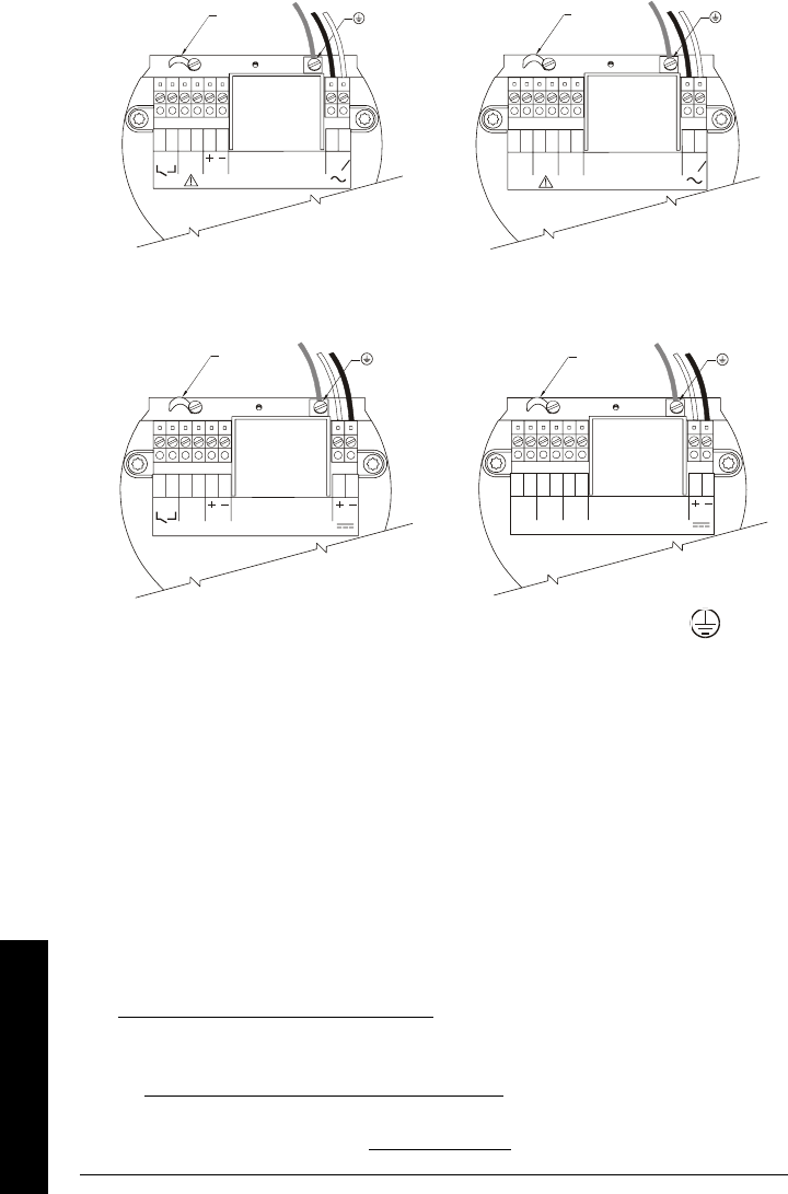
AC version
1 2
DC version
3. Connect the earth conductor of the power supply to the earth terminal on the
metal bracket inside the connection box. Adjust the cable length so that the earth
conductor would be last to disconnect if cable is pulled.
4. Tighten the cable gland and check the strain relief (pull and turn).
5. Screw the cover onto the connection box and hand tighten it. The sealing ring must
be clean and undamaged.
6. Reattach the cover lock on the connection cover.
1. Install in accordance with
Wiring and Installation
in the HART Application Guide
(order number HCF_LIT-34), available from :
http://www.hartcomm.org/technical/doclist.html.
2. Install in accordance with
PROFIBUS PA User and Installation Guidelines
(order
number 2.092), available from www.profibus.com.
1264 5
378
L
1
L
2
N
mA
Rated temperature of
connection cables must
exceed m aximum ambient
temperature by at least 15 K
1264 5
378
L
1
L
2
N
Rated temperature of
connection cables must
exceed maximum ambient
temperature by at least 15 K
PROFI-
BUS PA
HART wiring1PROFIBUS wiring2
earth
terminal
earth
terminal
cable clamp cable clamp
1264 5
378
mA
19-3 0 V
Rated tempera ture of
connection cables must
exceed maximum ambient
temperature by at least 15 K
12645378
PROFI-
BUS PA
19-30 V
Rated temperature of
connection cables must
exceed m aximum ambient
temperature by at least 15 K
HART wiring1PROFIBUS wiring2
earth
terminal
earth
terminal
cable clamp cable clamp

7ML19985JM01SITRANS LR 460 – INSTRUCTION MANUAL Page 21
mmmmm
Wiring
7. Connect the external earth terminal
located between the cable glands to a
ground connection at your vessel. Use a
cable with a diameter of 2.5 mm2.or
greater.
For error-free communication via the HART
protocol, a load of at least 230 Ω must be
available in the signal circuit.
SIEMENS
cable
glands
earth
(ground)
terminal

Page 22 SITRANS LR 460 – INSTRUCTION MANUAL 7ML19985JM01
mmmmm
Wirng
Hazardous area installations
Product Nameplate
Instructions specific to hazardous area installations
(Reference European ATEX Directive 94/9/EC,Annex II, 1/0/6)
The following instructions apply to equipment covered by certificate number DMT 01
ATEX E 038:
1. For use and assembly, refer to the main instructions.
2. The equipment is certified for use as Category 1/2 D equipment. The Essential
Health and Safety Requirements are assured by compliance with EN 50281-1-1:1998;
Dust Explosion Protection.
3. The equipment may be used with dust and fibers with apparatus temperature class
T. See table below.

7ML19985JM01SITRANS LR 460 – INSTRUCTION MANUAL Page 23
mmmmm
Wiring
• Permitted ambient temperature at the horn antenna (Category 1D):
- 20 °C ≤ Tamb ≤ +200 °C
• Permitted ambient temperature at the electronic enclosure (Category 2D):
-20 °C ≤ Tamb ≤ +65 °C
• Maximum permitted temperature within electronic enclosure (Category 1D):
85 °C
4. The equipment has not been assessed as a safety related device (as referred to by
Directive 94/9/EC Annex II, clause 1.5).
5. Installation and inspection of this equipment shall be carried out by suitably trained
personnel in accordance with the applicable code of practice (EN 60079-14 and
EN 60079-17 in Europe).
6. Repair of this equipment shall be carried out by suitably trained personnel in
accordance with the applicable code of practice (e.g. EN 60079-19 within Europe).
7. Components to be incorporated into or used as replacements in the equipment shall
be fitted by suitably trained personnel in accordance with the manufacturer's
documentation.
8. It is the responsibility of the user to ensure that manual override is possible in order
to shut down the equipment and protective systems incorporated within automatic
processes, which deviate from the intended operating conditions, provided that this
does not compromise safety.
9. Equipment Marking:
The equipment marking contains at least the information on the product label,
shown on page 22.
EU Equivalency
Any zener diode safety barrier, certified by an EU approved certification body to
[ EEx ia ] IIC, its output voltage (Uo) not exceeding 24 V and its output current (Io) limited
by load resistance (Ro); such that Io = Uo / Ro, does not exceed 250 mA.
Ambient temperature at the
horn antenna (Category 1D)
Maximum surface
temperature at the
horn antenna
(Category 1D)
Maximum surface temperature Category 2D
(electronic enclosure resp. flange)
- 20 °C ≤ Tamb ≤ + 60 °C 72 °C 70 °C at Tamb ≤ 65 °C in Category 2
- 20 °C ≤ Tamb ≤ + 100 °C 112 °C 100 °C independent from Tamb in Category 2
- 20 °C ≤ Tamb ≤ + 200 °C 212 °C 200 °C independent from Tamb in Category 2
Notes
• The installation must comply with national requirements.
• The safe area is unspecified except that it must not be supplied from nor contain,
under normal or abnormal conditions, a source of potential with respect to earth in
excess of 250 V rms or 250 V DC.

Page 24 SITRANS LR 460 – INSTRUCTION MANUAL 7ML19985JM01
mmmmm
Wirng

7ML19985JM01 SITRANS LR 460 (4-20 mA) – INSTRUCTION MANUAL Page II-25
mmmmm
mA: Startup
Part II: SITRANS LR 460
4-20 mA version

Page II-26 SITRANS LR 460 (4-20 mA) – INSTRUCTION MANUAL 7ML19985JM01
mmmmm
mA: Startup
4-20 mA Start Up
Only two steps are necessary for a Quick Setup (see page 29 for detailed instructions):
1. Use the handheld programmer to set the PROFIBUS address locally.
2. Use SIMATIC PDM to calibrate the four set points: High and Low Calibration Point,
and High and Low Level Point.
SITRANS LR 460 automatically starts up in RUN mode and detects the material level. The
LCD displays the material level referenced from the Low Level Point1 (the output of
Analog Input Function Block 1 or 2). System status is displayed on the LCD, or on a remote
communications terminal.2
Startup Display (RUN mode)
1 – Number of the active Analog Input Function Block (AIFB 1 or 2)
2 – Primary display: shows level, space, distance or volume (Output of the active AIFB)
3 – Units: the associated engineering units of the primary value (m, cm, mm, ft, in, or percent) if
applicable
4 – Echo status indicator: Reliable Echo or Unreliable Echo
The Reliable Echo icon is visible during normal operation.
If LOE is pending2 the x flashes, alternating with the two horizontal bars.
When LOE becomes active, the x becomes solid and the auxiliary display shows
fault code S: 0.
5 – Auxiliary display: shows distance,mA value (HART only), confidence, or temperature, in
response to request via Siemens Milltronics handheld programmer
6 – Heartbeat: a small heart-shaped icon flashes on and off once per second.
1. See
Calibration
on page 29 for an illustration.
Note: Frequently switching the device off and on causes wear of the electronics
(monitored using Parameter ???).
2. See
LOE Timer
on page 84 for more details.
2 98.82
3.800 mA
%
2 98.82
S: 0
%
Normal operation
134
2
Failsafe operation
5
1
6
34
2
56
7ML19985JM01 SITRANS LR 460 (4-20 mA) – INSTRUCTION MANUAL Page II-27
mmmmm
mA: Startup
Programming SITRANS LR 460
The parameters that control the operation of the LR 460 are organized into function
groups, and arranged in a 4-level menu structure that can be accessed either via the
handheld programmer, or via PDM (see
LCD menu structure
on page 37).
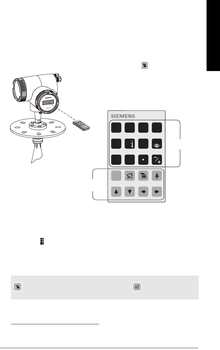
The handheld programmer1
To activate PROGRAM mode, point the handheld programmer at the display (from a
maximum distance of 600 mm [2 ft.]), and press the Mode key .
The handheld programmer has two modes of operation:
1. Navigation Mode
• In this mode, the rightmost digit of the menu number flashes (the Edit Mode
icon is not visible).
• Press Up or Down arrow to change the menu number.
• Press Right or Left arrow once to move to the next/previous menu level.
• Press Right arrow again to switch from Navigation to Edit Mode2, or vice versa.
1. See
Programming via the handheld programmer
on page 33 for more detail.
Note: For Quick Access to parameters via the handheld programmer, press Mode key
to activate PROGRAM mode, followed by Home key , then enter the menu
number (see
LCD menu structure
on page 37 for details).
2. When there is no further menu sub-level to access.
display
handheld
programmer
max. 600 mm
(2 ft.)
5
9
C
6
0
7 8
1 2 3 4
numeric keys
function
Keys

Page II-28 SITRANS LR 460 (4-20 mA) – INSTRUCTION MANUAL 7ML19985JM01
mmmmm
mA: Startup
2. Edit Mode
• In this mode, the Edit Mode icon appears and flashes.
• Pressing a number key enters parameter data.
• In the case of read-only parameters, no change is permitted.
PROGRAM Mode Display
1 – Menu level
2 – Parameter name
3 – Edit Mode indicator
4 – Value of current parameter
When you activate PROGRAM mode for the first time in any power cycle, the LCD
displays the first menu. If, during the same power cycle, you switch to RUN mode, and
then back to PROGRAM mode, then the LCD will display the menu or item that was last
accessed in PROGRAM mode.
Security
Local operation enable
Local Operation can be enabled or disabled via PDM. Go to Identification > Device > Local
Operation Enable and select the desired setting.
Remote operation enable
Remote Operation can be enabled or disabled via the handheld programmer. To change
the setting:
• Open Menu level 1: Identification.
• Scroll down to REMLOCK.
1. Identification
1.2. Configuration
1.2.3. Remote Lock
• To enable programming, set REMLOCK to 0. To disable programming, enter 1.
Note: only parameter items can be in Edit mode.
Note: SITRANS LR 460 continues to monitor In and Out values even when the device is
in PROGRAM mode.
1.3.1
0.01.18
SOFT REV
123
4

7ML19985JM01 SITRANS LR 460 (4-20 mA) – INSTRUCTION MANUAL Page II-29
mmmmm
mA: Startup
Write locking
Write locking prevents any changes to parameters, either via PDM or the handheld
programmer, but still allows access to the device.
Open the menu Device – Write Locking, and select On or Off.
How to do a Master Reset
Open the menu Device– Master Reset to access the reset options, including Factory
Reset.
Fault Reset
This resets the Fault message after an active fault has occurred and been corrected.
A manual reset is required only for certain faults, identified by an asterisk (*) in the table
General Fault Codes
on page 88.
To reset, key in the value of the fault code in question.
Quick Setup
Activating SITRANS LR 460
Power up the instrument. SITRANS LR 460 starts in RUN mode, and the LCD displays the
output of AIFB1 or AIFB2.
Performing calibration via PDM
Please consult the operating instructions or online help for details on using SIMATIC
PDM. (An Application Guide Connecting
SMPI HART instruments toSIMATIC PDM using
HART modem
is available on the product page of our website:
https://pia.khe.siemens.com/index.asp?Nr=11813Changing parameter settings
• First launch SIMATIC PDM, connect to SITRANS LR 460, and upload data from the
device.
• Adjust parameter values in the parameter view field (right side of screen).
• After adjusting the value, press Enter (the status fields read Changed).
• When you have completed the adjustments, open the Device menu, download data
to the device, and save parameter settings offline (the status fields go blank).
Calibration
Only four settings are required for a Quick Setup:
• High Calibration Point and High Level Point
• Low Calibration Point and Low Level Point
Note: Keep infrared devices such as laptops, cell phones, and PDAs, away from
SITRANS LR 460 to prevent inadvertent operation.

Page II-30 SITRANS LR 460 (4-20 mA) – INSTRUCTION MANUAL 7ML19985JM01
mmmmm
mA: Startup
1, 2, 3, 4.,,
Calibration – steps 1 to 7
1. Open the menu Device – Sensor Calibration and select the button Dry Calibration.
(Click on Additional Information to see the schematic showing the PROFIBUS
parameters.)
2. Enter the new value for Low Calibration Point (default units are meters).
3. Enter the corresponding value for Low Level Point in percent (default is 0).
4. Enter the new value for High Calibration Point (default units are meters).
5. Enter the corresponding value for High Level Point in percent (default is 100).
6. Click on Transfer.
7. SITRANS LR 460 is now ready to operate.
Using Auto False Echo Suppression
If SITRANS LR 460 displays a false high level, or the reading is fluctuating between the
correct level and a false high level, you can use the Auto False Echo Suppression
parameters to prevent false echo detection. See
TVT (Auto False Echo Suppression)
setup
on page 68 for instructions.
1. The point to which all of the above parameters are referenced. For the standard rod
antenna, see
SITRANS LR 460 Dimensions
on page 10.
2. Sensor Offset is a negative value (see
Sensor Offset (default 0)
on page 64 for more
detail).
3. The value produced by the echo processing, representing the distance from the
Sensor Reference Point to the target.
4. Level Value: the level measured in level units.
High Level Point
(default: 100%)
Sensor Reference Point1
Sensor Value3
Low Level Point
(default: 0%)
Level4
Level Offset
Secondary Value 1
Low Calibration
Point
Sensor Offset2
High
Calibration
Point
Far Range
Near Range
tank reference point
7ML19985JM01 SITRANS LR 460 (4-20 mA) – INSTRUCTION MANUAL Page II-31
mmmmm
mA: Startup
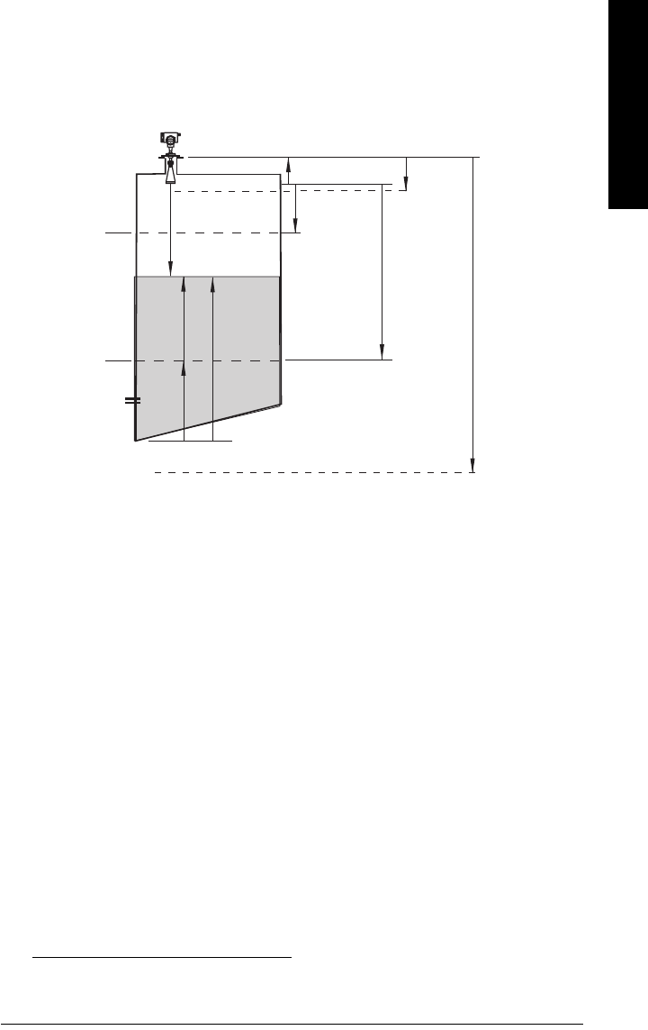
Level application example
If volume conversion is not selected, Primary Value (PV) will be level (SV1). SV1 is the sum
of level plus level offset (if any). 1
1. For standard configuration reference point, see
SITRANS LR 460 Dimensions
on page
10.
Sensor Reference
Point1
Sensor Value
SV2
Low Level Point
= 0%
Level
Sensor Offset
High
Calibration
Point = 3 m
High Level
Point = 100%
Near
Range
Far Range
Level Units: Sensor Units:
Low
Calibration
Point = 5 m
Level
Offset
(if
any) Secondary Value 1

Page II-32 SITRANS LR 460 (4-20 mA) – INSTRUCTION MANUAL 7ML19985JM01
mmmmm
mA: Startup

7ML19985JM01 SITRANS LR 460 – INSTRUCTION MANUAL Page 33
mmmmm
C: Local Operation
Local Operation
Programming via the handheld programmer
Although the complete range of parameters is only accessible via PDM1, you can access
and adjust many of the parameters via the Siemens Milltronics infrared handheld
programmer.
• For the complete list of parameters, see
Appendix A: Parameter Descriptions
on
page 58.
•
LCD menu structure
on page 37 gives a list of all parameters accessible via the
handheld programmer, preceded by the menu number.
Parameter Menu Structure
The parameters are organized into function groups, and arranged in a 4-level menu
structure. For example:
1. Identification
1.2. Configuration
1.2.2. Remote Lock.
The LCD Display
Details on the LCD display are given in
Start Up
, page 24 onwards.
r
1. Please see page 46 for
Remote operation via PROFIBUS PA
Note: The ARROW buttons shown below are required for programming
this product. The additional buttons on the hand programmer do not
apply to SITRANS LR 400.
Key Programming Mode
Parameter scroll UP
Parameter scroll DOWN
LEFT Arrow (or CANCEL)
RIGHT Arrow (or ENTER)
C
SITRANS LR 400
buttons
Page 34 SITRANS LR 460 – INSTRUCTION MANUAL 7ML19985JM01
mmmmm
C: Local Operation
Using the handheld programmer
Detailed instructions on using the handheld programmer start on page 25, and on doing a
Quick Setup start on page 27.
The following pages give details on how to programme some of the more complex
SITRANS LR 460 parameters via the handheld programmer.
Security
Local operation enable
Local Operation can be enabled or disabled via PDM. Go to Identification > Device > Local
Operation Enable and select the desired setting.
Write locking
Write locking prevents any changes to parameters, either via PDM or the handheld
programmer, but still allows access to the device.
1. Go to Write Locking:
1. Identification Menu
1. 3. Configuration
1.3.5. Lock
2. Press Right ARROW to open Edit mode.
3. Key in 2547 (unlock value) to enable parameter changes.
4. Press Right ARROW again, to accept the change and return to Navigation
mode.
Remote operation enable
Remote Operation can be enabled or disabled via the handheld programmer.
To change the setting:
•Open Identification Menu, then scroll down to CONFIG.
• Press Right ARROW to open the Config Menu, then scroll down to REMLOCK.
1. Identification
1.2. Configuration
1.2.2. Remote Lock
• To enable programming, set REMLOCK to 0. To disable programming, enter 1.
Note: For Quick Access to parameters via the handheld programmer, press the mode
key to activate PROGRAM mode, then key in the menu number.
Values 2547 (unlock value) Off Enables parameter changes
any other value On Disables parameter changes
Values 0Remote operation enabled
1Remote operation disabled

7ML19985JM01 SITRANS LR 460 – INSTRUCTION MANUAL Page 35
mmmmm
C: Local Operation
How to do a Master Reset
Master Reset
Example: do a Profile reset
1. Go to Reset:
1. Identification Menu
1. 2. Configuration
1.2.3. Reset
2. Press the Right ARROW key to open Edit mode.
3. Key in 1 (Profile Reset) to reset all parameters except PROFIBUS address.
4. Press the Right ARROW key again, to accept the changes and return to
Navigation mode.1
Individual Parameter Reset
1. Press Right ARROW , then CLEAR , then Right ARROW .
2. The value returns to the default factory setting.
Fault Reset
Used to reset a fault message after an active fault has occurred and been corrected. A
manual reset is required only for certain faults, identified by an asterisk (*) in the General
Fault Code list on page 51.
To reset, key in the value of the fault code in question.
1. Go to Reset Fault:
1. Identification Menu
1. 2. Configuration
1.2.4. Reset Fault
2. Press the Right ARROW key to open Edit mode.
3. Key in the number of the Fault Code to reset the status to normal operation.
Note: Following a Master Reset, complete reprogramming is required.
1Reset all parameters (except PROFIBUS address) to PROFIBUS PA profile
default values
Values 2506 Warm Start: restart the device (this option is rarely used)
2712 Reset PROFIBUS address to 126
32768 Reset to manufacturer’s default values (factory settings)1
1. Manufacturer’s settings:
AIFB Filter Time Constant = 10 s
LTB values set for 0 - 20 m (Low and High Calibration points; Near Range and Far Range)
C

Page 36 SITRANS LR 460 – INSTRUCTION MANUAL 7ML19985JM01
mmmmm
C: Local Operation
4. Press the Right ARROW key again, to accept the change and return to
Navigation mode.
Device calibration
Only four settings are required for a Quick Setup: High Calibration Point, Low Calibration
Point, High Level Point, and Low Level Point. (For an illustration, see
Calibration
on
page 28.)
2.3. Sensor Calibration:
2.3.1. Sensor Units (default meters)
2.3.2. Calibration Type.
2.3.3. Low Calibration Pt.
2.3.4. High Calibration Pt.
2.3.5. Unit [Level] (default percent)
2.3.6. Low Level Point
2.3.7. High Level Point
1. Go to Calibration Type and verify that "Dry" Calibration is selected.
2. Go to Low Calibration Point and enter the new value (default units are meters).
3. Go to High Calibration Point and enter the new value (default units are meters).
4. Go to Low Level Point and enter the corresponding value in percent (default is 0).
5. Go to High Level Point and enter the corresponding value in percent (default is 100).
6. SITRANS LR 460 is now ready to operate.
Values 0*
"Dry" calibration
1"Wet" calibration (not recommended for SITRANS LR 460)

7ML19985JM01 SITRANS LR 460 – INSTRUCTION MANUAL Page 37
mmmmm
E: LCD menus
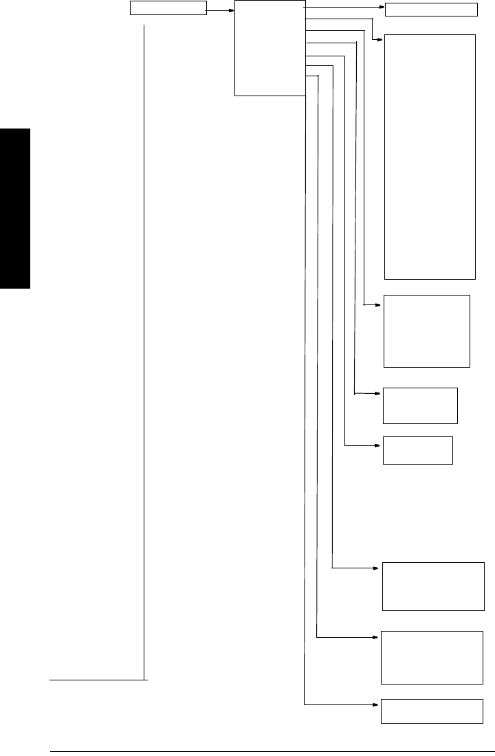
LCD menu structure
FOR PLACEMENT ONLY - TO BE REPLACED WITH FLIPOUT PAGE
1. Identification
1. Reset Filter
2. Standard Setup
3. Sensor Calibration’
4. Measuring Limits
5. Linearization
6. Detailed Setup
Input
Sensor Calibration
2. Configuration
3. Device
4. Statistics
1. Powered Hours
2. Powered Resets
Statistics
1. Temperature Unit
2. PV Unit
3. Sensor Units
Operation
1. Sensor Unit
2. Calibration Type
3. Low Calibration Pt.
4. High Calibration Pt.
5. Unit (Level)
6. Low Level Point
7. High Level Point
8. Level Offset
9. Sensor Offset
A. Temperature Unit
1. PV (volume/level) Unit
2. Linearization/Tank Shape
3. Linearization Volume
4. Dimension A
5. Dimension L
Linearization
1. Response Rate
2. Echo Lock
1. Address
2. Remote Lockout
3. Factory Reset
4. Reset Fault
5. Menu Timeout
Configuration
1. Software Revision
2. Loader Revision
3. Hardware Revision
4. PROFIBUS Ident Number
5. Lock
6. Language
Device
1. Min. Measurement Value
2. Max. measurement Value
3. Lower Value Min
4. Upper Value Max.
5. Process Temperature Min
6. Process Temperature Max
Measuring Limits
Standard Setup
See Output: page 39
Output
2. Input
3. Output
Identification
Page 38 SITRANS LR 460 – INSTRUCTION MANUAL 7ML19985JM01
mmmmm
E: LCD menus
FOR PLACEMENT ONLY - TO BE REPLACED WITH FLIPOUT PAGE
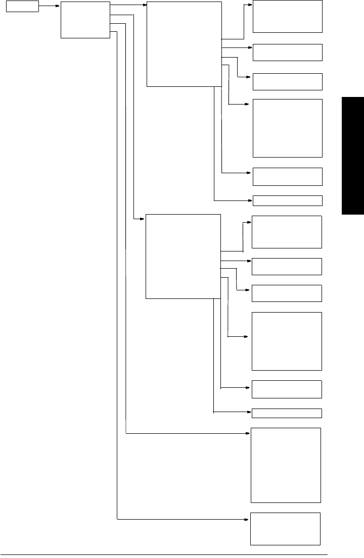
Detailed Setup
1. Failsafe
2. Volume
3. Echo select
4. Echo sampling
5. Range
6. TVT setup
7. TVT shaper
8. Rate
Echo select
Range
Failsafe
1. Near Range
2. Far Range
1. LOE Timer
8. Detailed Setup
Input
Table A 1. Level 1
2. Volume 1
3. Level 2
4. Volume 2
5. Level 3
6. Volume 3
7. Level 4
8. Volume 4
Table B 1. Level 5
2. Volume 5
3. Level 6
4. Volume 6
5. Level 7
6. Volume 7
7. Level 8
8. Volume 8
Table C 1. Level 9
2. Volume9
3. Level 10
4. Volume 10
5. Level 11
6. Volume 11
Volume
1. Algorithm
2. Threshold Long
3. Marker
4. Shots
5. Velocity
6. Propagation Factor
Echo Sampling
1. Sampling up
2. Sampling down
3. Window
TVT setup
1. TVT Hover Level
2. Auto TVT
3. Range
4. Shaper Mode
TVT Shaper
1. Shaper A (1-9)
2. Shaper B (10-18)
3. Shaper C (19-27)
4. Shaper D (28-36)
Rate
1. Fill rate
2. Empty rate
7ML19985JM01 SITRANS LR 460 – INSTRUCTION MANUAL Page 39
mmmmm
E: LCD menus
1. AIFB1
2. AIFB2
3. mA Output
4. Relay Config
1. Target Mode
2. Unit
3. Filter Time Constant
4. Channel
5. Batch Information
6. Process Value Scale
7. Output Scale
8. Output Limits
9. Failsafe Mode
A. Interface
1. Failsafe Mode
2. Failsafe Value
Output AIFB1
Failsafe Mode
3. Output 1. Batch ID
2. Batch Unit
3. Batch operation
4. Batch Phase
Batch Information
1. Lower Value
2. Upper Value
Process Value Scale
Output Scale
1. Lower Value
2. Upper Value
Output Limits
1. Lower Limit Alarm
2. Lower Limit Warning
3. Upper Limit Warning
4. Upper Limit Alarm
5. Limit Hysteresis
6. Min. Out
7. Max Out
A. Decimal Point
Interface
1. Target Mode
2. Unit
3. Filter Time Constant
4. Function
5. Batch Information
6. Process Value Scale
7. Output Scale
8. Output Limits
9. Failsafe Mode
A. Interface
1. Failsafe Mode
2. Failsafe Value
AIFB2
Failsafe Mode
1. Batch ID
2. Batch Unit
3. Batch operation
4. Batch Phase
Batch Information
1. Lower Value
2. Upper Value
Output Scale
1. Lower Value
2. Upper Value
Output Limits
1. Lower Limit Alarm
2. Lower Limit Warning
3. Upper Limit Warning
4. Upper Limit Alarm
5. Limit Hysteresis
6. Min. Out
7. Max Out
A. Decimal Point
Interface
Process Value Scale
1. Function
2. Output value
3. Manual value
4. Min limit
5. Max limit
6. FS mode
7. FS value
8. 4 mA Trim
9. 20 mA Trim
mA Output
1. AIFB
2. Function
3. NC/NO
4. State
Relay config

Page 40 SITRANS LR 460 – INSTRUCTION MANUAL 7ML19985JM01
mmmmm
E: LCD menus
5. Maintenance
settings
1. Remaining Device
Lifetime
2. Remaining Sensor
Lifetime
3. Service Interval
4. Calibration Interval
1. Time Elapsed Since Last Service
2. Maintenance Required Limit
3. Maintenance Demanded Limit
4. Maintenance Alert Activation
5. Total Service Interval
6. Units
7. Maintenance Status
8. Acknowledge Status
9. Acknowledge
Service Interval
1. Time Elapsed Since Last Calibration
2. Maintenance Required Limit
3. Maintenance Demanded Limit
4. Maintenance Alert Activation
5. Total Calibration Interval
6. Units
7. Maintenance Status
8. Acknowledge Status
9. Acknowledge
1. Total Device Operating Time
2. Remaining Device Lifetime
3. Maintenance Required Limit
4. Maintenance Demanded Limit
5. Maintenance Alert Activation
6. Total Expected Device Life
7. Maintenance Status
8. Acknowledge Status
9. Acknowledge
Remaining
Device Lifetime
1. Total Sensor Operating Time
2. Remaining Sensor Lifetime
3. Maintenance Required Limit
4. Maintenance Demanded Limit
5. Maintenance Alert Activation
6. Total Expected Sensor Life
7. Maintenance Status
8. Acknowledge Status
9. Acknowledge
Remaining Sensor Lifetime
Maintenance
settings
Calibration Interval

7ML19985JM01 SITRANS LR 460 – INSTRUCTION MANUAL Page 41
mmmmm
D: HART Communications
HART Communications
Highway Addressable Remote Transducer, HART, is an industrial protocol that is
superimposed on the 4-20 mA signal. It is an open standard, and full details about HART
can be obtained from the HART Communication Foundation at www.hartcomm.org
SITRANS LR 460 can be configured over the HART network using either the HART
Communicator 275 by Fisher-Rosemount, or a software package. There are a number of
different software packages available. The recommended software package is the
SIMATIC Process Device Manager (PDM) by Siemens.
HART Device Description (DD)
In order to configure a HART device, the configurator must have the HART Device
Description for the instrument in question. HART DDs are controlled by the HART
Communication Foundation. Please check with the HART Communication Foundation for
the availability of the HART DD for SITRANS LR 460. Older versions of the library will have
to be updated in order to use all the features of SITRANS LR 460.
SIMATIC Process Device Manager (PDM)
This software package is designed to permit easy configuration, monitoring, and
troubleshooting of HART devices. The HART DD for SITRANS LR 460 was written with
SIMATIC PDM in mind and has been extensively tested with this software.
The Device Description for SIMATIC PDM may be downloaded from the product page of
our website at: https://pia.khe.siemens.com/index.asp?Nr=7427, under Downloads.
All parameters accessible via the HART Communicator are also accessible via PDM. In
addition, the Maintenance parameters listed below are accessible via PDM only.
Maintenance settings (accessible via PDM only)
Device Lifetime
Total Device Operating Time
Remaining Device Lifetime
Maintenance Required Limit
Maintenance Demanded Limit
Maintenance Alert Activation
Total Expected Device Life
Units
Maintenance Status
Acknowledge Status
Acknowledge

Page 42 SITRANS LR 460 – INSTRUCTION MANUAL 7ML19985JM01
mmmmm
D: HART Communications
Sensor Lifetime
Total Sensor Operating Time
Remaining Sensor Lifetime
Maintenance Required Limit
Maintenance Demanded Limit
Maintenance Alert Activation
Total Expected Sensor Life
Units
Maintenance Status
Acknowledge Status
Acknowledge
Service Interval
Time Elapsed Since Last Service
Maintenance Required Limit
Maintenance Demanded Limit
Maintenance Alert Activation
Total Service Interval
Units
Maintenance Status
Acknowledge Status
Acknowledge
Calibration Interval
Time Elapsed Since Last Calibration
Maintenance Required Limit
Maintenance Demanded Limit
Maintenance Alert Activation
Total Calibration Interval
Units
Maintenance Status
Acknowledge Status
Acknowledge
Supported HART Commands:
SITRANS LR 460 conforms to HART rev. 5 and supports the following:
Universal Commands
0, 1, 2, 3, 6, 11, 12, 13, 14, 15, 16, 17, 18, 19
Common Practice Commands
34, 38, 40,41, 42, 44, 45, 46, 48, 59

7ML19985JM01 SITRANS LR 460 – INSTRUCTION MANUAL Page 43
mmmmm
D: HART Communications
Universal and Common Practice Commands
For details on the Universal and Common Practice Commands, please contact the HART
Communication Foundation.
Device Specific Commands
For a document containing the Device Specific Commands, please contact Siemens
Milltronics at techpubs.smpi@siemens.com.

Page 44 SITRANS LR 460 – INSTRUCTION MANUAL 7ML19985JM01
mmmmm
D: HART Communications
Notes

7ML19985JM01 SITRANS LR 460 (PROFIBUS PA) – INSTRUCTION MANUAL Page III-45
mmmmm
PA: Remote Operation
Part III: SITRANS LR 460
PROFIBUS PA version

Page III-46 SITRANS LR 460 (PROFIBUS PA) – INSTRUCTION MANUAL 7ML19985JM01
mmmmm
PA: Remote Operation
Remote operation via PROFIBUS PA
SITRANS LR 460 is a Class B, Profile Version 3.0, PA device. It supports Class 1 Master for
cyclic and acyclic data exchange, and Class 2 for acyclic services. The full range of
SITRANS LR 460 functions is available only over a PROFIBUS PA network.
PROFIBUS PA is an open industrial protocol. Full details about PROFIBUS PA can be
obtained from PROFIBUS International at www.profibus.com.
To use PROFIBUS PA, you will need a PC configuration tool: we recommend
SIMATIC PDM. Please consult the operating instructions or online help for details on
using SIMATIC PDM. (You can find more information at www.fielddevices.com: go to
Products and Solutions > Products and Systems > Process Device Manager.)
SIMATIC PDM
SIMATIC PDM is a software package for designing, parameterizing, commissioning,
diagnosing and maintaining SITRANS LR 460 and other process devices.
SIMATIC PDM contains a simple process monitor of the process values, alarms and
status signals of the device. Using SIMATIC PDM you can
•display
•set
•change
•compare
• check the plausibility of
•manage
• simulate
process device data.
Device Description
In order to use Process Device Manager (PDM) with PROFIBUS PA, you will need the
Device Description for SITRANS LR 200, which will be included with new versions of
PDM. You can locate the Device Description in Device Catalog, under Sensors/Level/
Echo/Siemens Milltronics. If you do not see SITRANS LR 460 under Siemens Milltronics,
you can download it from our web site. Go to the SITRANS LR 460 product page at https:/
/pia.khe.siemens.com/index.asp?Nr=7427 and click Downloads. After downloading the
DD file, you need to execute DeviceInstall.

7ML19985JM01 SITRANS LR 460 (PROFIBUS PA) – INSTRUCTION MANUAL Page III-47
mmmmm
PA: Remote Operation
Configuration
To configure a PROFIBUS PA Class 1 Master (for example, a PLC), you will need a GSD
file.
The GSD file
The GSD file SIEM810F.gsd is available from the SITRANS LR 460 product page on our
web site. Go to https://pia.khe.siemens.com/index.asp?Nr=7427 and click Downloads.
Download the DeviceInstall, and run it from your computer. This will install the GSD file
into your system (as long as you are using SIMATIC software).
Setting the PROFIBUS address
When your instrument is shipped, the PROFIBUS address is set to 126. You can set it
locally (see
Setting the PROFIBUS address via the handheld programmer
on page 27) or
remotely via the bus, using a parameterization tool such as SIMATIC PDM (see
Address
(default 126)
on page 58).
PROFIBUS address
Bus Termination
Power Demands
To determine how many devices can be connected to a bus line, calculate the combined
maximum current consumption of all the connected devices: 10.5 mA for SITRANS LR 200.
Allow a current reserve for safety.
Cyclic versus Acyclic Data
When you request data from a device via PROFIBUS PA, you have two choices. Cyclic
data is provided at every bus scan: acyclic data is requested and provided as needed.
Input information is always requested at every bus scan and is set up as cyclic data.
Configuration information is only needed periodically and is set up as acyclic data.
Note: If you are not using SIMATIC software, you can download the GSD file
separately, and import it with the software you are using.
Values Range: 0 to 126
Pre-set: 126
Note: PROFIBUS PA MUST be terminated at both extreme ends of the cable for it to
work properly. Please refer to the PROFIBUS PA User and Installation Guidelines (order
number 2.092), available from www.profibus.com.

Page III-48 SITRANS LR 460 (PROFIBUS PA) – INSTRUCTION MANUAL 7ML19985JM01
mmmmm
PA: Remote Operation
Cyclic Data
When you configure SITRANS LR 460 on the PROFIBUS PA bus, there are two slots
available for modules.
Slot 0 always transmits AIFB1 information1; slot 1 defaults to Free Place, but can be
changed to AIFB2 information. If you do not wish to have data transmitted, then you must
use a Free Place module in that slot.
Each of the two Analog Input Function Blocks can be set up to return Level, Distance, or
Volume. Within the function blocks, the values are scaled according to the user
requirements (see
Analog Input Function Blocks 1 and 2
on page 55 for details).
AIFB1 and AIFB2 return 5 bytes of data each:
The first 4 bytes are the floating point representation (IEEE) of the variable. The variables
are the outputs of the function block. The 5th byte is the status word and the list of
possible values is given in the chart below.
The 5 bytes must be read consistently, in a contiguous chunk: they cannot be read byte by
byte, and cannot suffer an interrupt. If you are using an S7-300 / 400, you will need to use
SFC14 DPRD_DAT: Read Consistent Data of a Standard PD Slave.
Status Byte
Note: Each of the slots has to have a module defined in it.
1. See
Analog Input Function Blocks 1 and 2
on page 55 for more information.
Status Codes for Good Quality
Values in hex notation Description
0x80 Data is GOOD.
0x84 A parameter in the function block has been changed: status
active for 10 s
0x89 Active low warning.
0x8A Active high warning.
0x8D Active low alarm.
0x8E Active high alarm.
Floating Point Status
AIFB2
AIFB1 byte 1 byte 2 byte 3 byte 4 byte 5
byte 6 byte 7 byte 8 byte 9 byte10byte10

7ML19985JM01 SITRANS LR 460 (PROFIBUS PA) – INSTRUCTION MANUAL Page III-49
mmmmm
PA: Remote Operation
Diagnostics
All diagnostic information shown below is viewable via PDM.
Diagnosis reply (applies only to cyclic masters)
This is a response to a GET-DIAG message.
During DPV0 data exchange, the PROFIBUS PA slave will notify the Master when a
serious error occurs. The Master will then send a Diagnosis request. The reply to this
request is normally logged in the PLC and is referred to as the "Hex values."
The reply may contain two parts. The first part is 6 bytes long and is defined by the
PROFIBUS standard. If there is a second part, it is called the ’extended diagnostic’ and it
is eight bytes long. The last four bytes of the extended diagnostic message give the error
code shown below. (The same information is also available acyclically via the Diagnosis
Object.
Status Codes for Bad Quality
Values in hex notation Description
0x10 The LOE timer has expired: this could be caused by
LOE or by a sensor malfunction: value is BAD.
0x01 There is an error in the configuration of the function
blocks in PROFIBUS PAa.
0X1F
The function block has been placed out of service.
(You will see this only if you read status word via
acyclic services, after placing the function block out of
service.)
0xC4 Bad configuration: value is BAD.
0XDE AI block out of service: value is BAD.
a. This could happen when a firmware download has been done, but a system
reset has not been done. This could also happen if the function blocks are not
configured properly using PDM or acyclic services.
Status Codes for Uncertain Quality
Values in hex notation Description
0x4B Value is a substituted value (normally used in Failsafe).
0x4C/0x4F Initial value.
0x47 Last usable value.

Page III-50 SITRANS LR 460 (PROFIBUS PA) – INSTRUCTION MANUAL 7ML19985JM01
mmmmm
PA: Remote Operation
Acyclic Diagnostics
This consists of four bytes.
Values of the DIAGNOSIS bit:
0 = not set
1 = set
Hex values Byte Bit Description
Indication
classa
a. R indicates the message remains active as long as the reason for the message
exists.
A indicates the message will automatically reset after 10 seconds
0x01000000
0
0 Electronics failure R
0x02000000 1 Mechanical failure R
0x04000000 2 Motor Temperature too high R
0x08000000 3 Electronics temperature too high R
0x10000000 4 Memory error R
0X20000000 5 Measurement failure R
0X40000000 6 Device not initialized (no calibration) R
0x80000000 7 Self calibration failed R
0x00010000
1
0Zero point error (limit position) R
0x00020000 1Power supply failure (electrical, pneumatic) R
0x00040000 2Configuration invalid R
0x00080000 3New startup carried out (Warm Start) A
0x00100000 4Restart carried out (Cold Start) A
0X00200000 5Maintenance required R
0X00400000 6Characterization invalid R
0X00800000 7
Set to 1 (one), if the Ident_Number of the
running cyclic data transfer and the value of
Physical Block IDENT__NUMBER_SELECTOR
parameter are different.
R
2 0 to 7 Reserved for use within the PNO
30 to 6 Reserved for use within the PNO
0X00000080 7More diagnosis information is available

7ML19985JM01 SITRANS LR 460 (PROFIBUS PA) – INSTRUCTION MANUAL Page III-51
mmmmm
PA: Remote Operation
Acyclic Extended Diagnostics (General Fault Codes)
In addition to the extended diagnostics available by cyclic data exchange (shown above),
further extended diagnostics are available via acyclic communications. This consists of
six bytes. See
Appendix B: Asynchronous Communications Data Map
on page 58 , for the
location of Extended Diagnostics
For a table listing the fault codes, meanings, and suggested corrective action to take, see
General Fault Codes
on page 88.
Acyclic Data
SITRANS LR 460 supports up to four simultaneous connections by a Class 2 Master
(C2 connection). It supports one connection by a Class 1 Master (C1 connection). A list of
all acyclic data, including address (slot and index), format, range of values, start value,
and attributes, can be found at
Appendix B: Asynchronous Communications Data Map
on page 58.
Configuration Example
To configure and use PROFIBUS PA with an S7-300/ 400 PLC
1. If SITRANS LR 460 is not listed in the STEP 7 device catalog, you can download the
DeviceInstall file from the Siemens Milltronics Web site and run it from your
computer. Go to https://pia.khe.siemens.com/index.asp?Nr=7427 and click
Downloads.
2. Add the SITRANS LR 460 "rack": click and drag the SITRANS LR 460 folder from the
hardware catalog.
3. Fill the rack with desired modules, by dragging and dropping them from the
hardware catalog.
4. After configuring PROFIBUS PA in steps 2 and 3, download it to the PLC.
5. Add code to the PLC program to read data consistently using the SFC14.
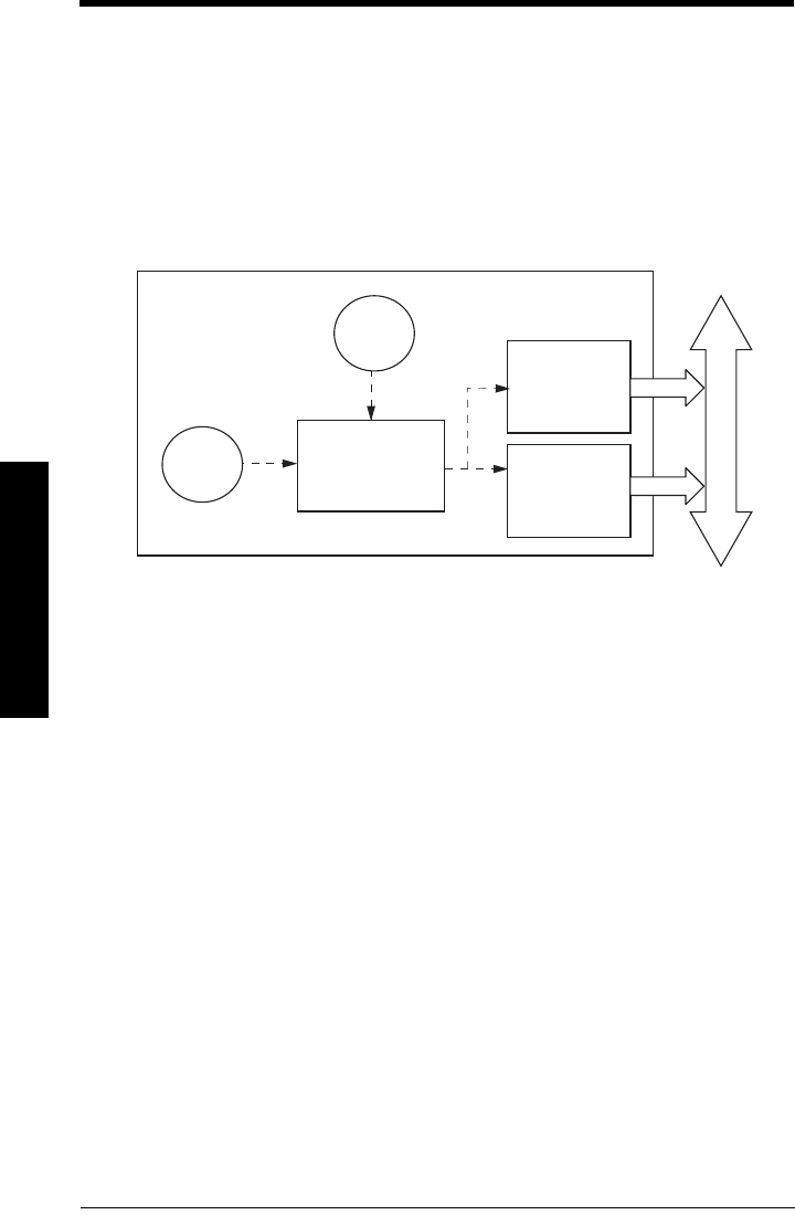
Page 52 SITRANS LR 460 – INSTRUCTION MANUAL 7ML19985JM01
mmmmm
Profi;e structure
PROFIBUS PA Profile Structure
PROFIBUS Level Device Design
The device follows the profile block model and is implemented as a Profile 3.0, Class B,
PA device. Standard profile parameters are used to program the level transducer block.
Block Model for recording and processing measured values
The functions of the device are divided into blocks for different areas of responsibility.
They can be parameterized by acyclic data transfer via PDM.
The device is implemented with one Physical Block (PB1), one Level Transducer Block
(LTB1), and two Analog Input Function Blocks (AIFB1 and AIFB2).
All data is viewed from the perspective of the DCS or PLC, so information from the sensor
is an input.
Transducer Block (TB)
The Level Transducer Block (LTB) carries out adjustments to the sensor, such as level
calibration and volume calibration. It supplies the outputs utilized by either or both of the
AIFBs.
Analog Input Function Blocks AIFB1 and AIFB2
The two AIFBs are completely independent of each other. They utilize the output from the
Level TB, and apply any required quality checks, scaling, and Failsafe operation
selections.
The output of an Analog Input Function Block supplies the measured value and
associated status information to PROFIBUS PA, via cyclic data transfer.
sensor
sensor
Transducer Block
electronics
temperature
Analog Input
Function Block2
Analog Input
Function Block1
PROFIBUS PA
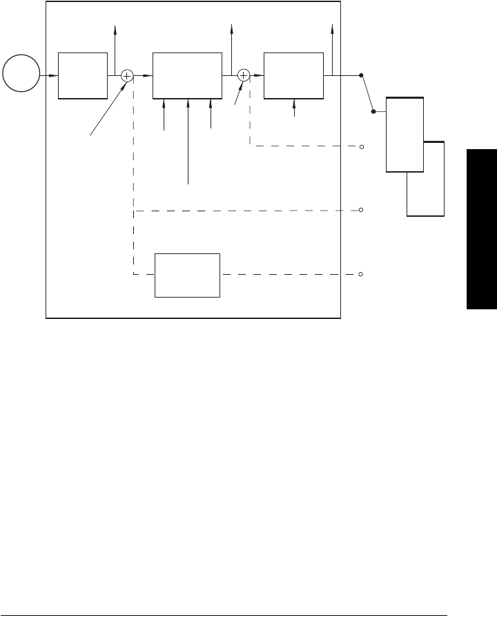
7ML19985JM01 SITRANS LR 460 – INSTRUCTION MANUAL Page 53
mmmmm
Profile structure
Description of the blocks
Transducer block function groups
The figure below shows the signal flow of measured values from the sensor through the
Transducer block into the output value (Primary Value/ Level or Volume; Secondary Value
1 / Level; Secondary Value 2 /Distance 1; or Secondary Value 3 / Distance 2). The Level TB
implements all of the basic parameters (see parameter diagram on page 54), including
level to volume calculation, if that option has been selected.
How the LTB works:
1. The sensor technology block selects the proper echo. For an explanation of sensor
technology, please refer to
Appendix B: Technical Reference
, page 82 onwards.
The sensor value (in sensor units) is checked to see if it is within its measuring limits.
If the limit is exceeded, this results in a Bad status and the error message Failure in
measurement. The sensor value is stored in Sensor Value.
The analog signal from the sensor is transformed into a digital signal.
A Sensor Offset (default 0) provides compensation if necessary for changes in the
sensor.
Level Transducer Block
Sensor Value
Sensor Sensor
technology
Level
calibration Linearization
Level Primary Value
[Level/Volume]
(level/volume units)
(Analog
Input)
AIFB1
Secondary Value 1
[Level]
(Level Units)
Secondary Value 2
[Distance 1]
(Sensor Units)
Sensor
Offset
Level
Offset
High
Calibration
Point
High Level
Point
Low
Calibration
Point
Low Level
Point
Calibration
Type
Linearization
Type
Secondary Value 2
[Distance 2]
(Level Units)
Sensor
Level unit
conversion
PV
SV1
SV2
SV3
AIFB2
(Analog
Input)
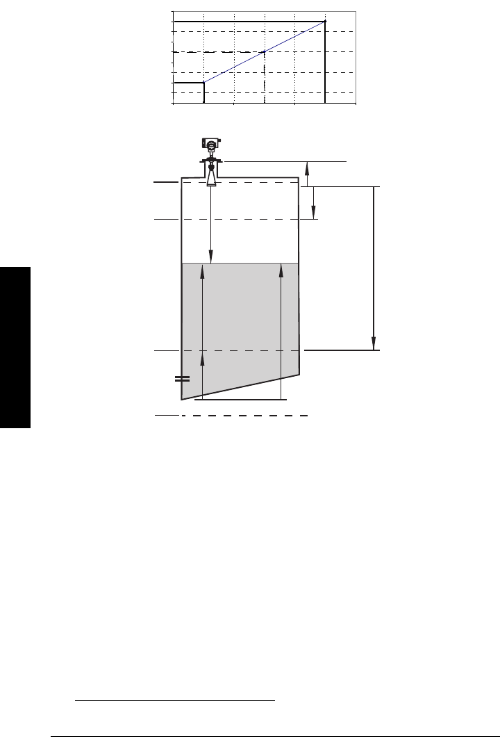
Page 54 SITRANS LR 460 – INSTRUCTION MANUAL 7ML19985JM01
mmmmm
Profi;e structure
2. Level Calibration is a linear transfer function that converts a sensor value to a level
value. The level value is used for volume calculation, if that function is enabled.1
3. Then linearization can be carried out to accommodate complex tank shapes, or to
provide level to volume conversion.
4. The LTB provides four possible outputs
• Primary Value (PV) / Level or Volume
• Secondary Value 1 (SV1) / Level
• Secondary Value 2 (SV2) / Distance1 (sensor units)
or
• Secondary Value 3 (SV3) / Distance 2 (any level units, except %)
1. Level Offset (default O) can compensate for specific tank configurations.
0
0.5
1
1.5
2
2.5
3
3.5
4
4.5
Low Calibration Point Sensor Value High Calibration Point
Level
High Level Point
Low Level Point
Calibration
Level Value
High Level Point
(default: 100%)
Sensor Reference
Point (flange face)
Sensor Value
Low Level Point
(default: 0%)
Level
Level Offset1
Secondary Value 1
Low Calibration Point
Sensor Offset
High
Calibration
Point
(distance 1 or 2)
SV2 or SV3
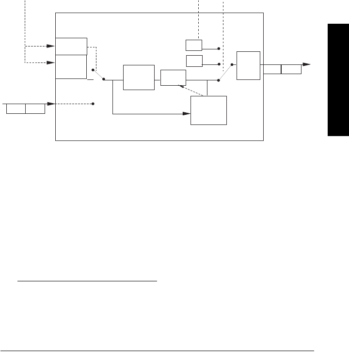
7ML19985JM01 SITRANS LR 460 – INSTRUCTION MANUAL Page 55
mmmmm
Profile structure
Electronics temperature
The transducer block also monitors the internal temperature of the device electronics. If
the temperature exceeds permitted limits, it does not change the sensor value, but it does
change the status.The permitted limits correspond to those of the permitted ambient
temperature.
If a temperature limit is exceeded, the status changes. Peak indicators1 allow you to
check the maximum and minimum temperatures that have occurred.
Analog Input Function Blocks 1 and 2
The figure below shows how measured values are processed within the two Analog
Input Function Blocks (AIFB1 and AIFB2) to produce the device outputs, which are
communicated via cyclic transfer to PROFIBUS PA, and displayed on the LCD.
Analog Input Function Block function groups (simulation, mode and status)2
1. Open View menu, scroll down to Peak Values, and click on Temperature tab in the
Peak Values window.
2. The output from the Level Transducer Block can be called the Primary Value (or
Secondary Value). When it becomes the input to the AIFB, it is called the Process
Variable.
enable
on
FB
algorithm
Status
OUT
AUTO
MODE and
STATUS
handling
Process Variable2
from LTB
(Function Block
input)
Value Status
Alarm
Limit
Check
Out of
Service
OUT
OUT
MAN
Value
simulate
value and
status
Value Status
Operator Operator
off
Simulate
Parameter
Failsafe

Page 56 SITRANS LR 460 – INSTRUCTION MANUAL 7ML19985JM01
mmmmm
Profi;e structure
How the AIFBs work
The Analog Input Function Blocks allow you to control modifications to the output value
(PROFIBUS cyclic data).
Output Conversion
Values transmitted by the Level TB have a status attached. The decision on what to do
with each value is made by the Analog Input Function Block.
Device/ Input Simulation
The input can be a simulated value instead of a TB OUT value. This allows the AI block to
be tested independently of the characteristics of the environment.
Failsafe
• If the status of the Primary Value or Simulation Value is bad, the fault logic can
output either the last usable measured value, or a given substitute value.
Device / Output Simulation
One of three settings can be selected:
• The result is the output parameter (OUT).
AIFB execution steps:
The AIFBs can provide a linear conversion to any desired units.
1. The input value is normalized (Scaling Input)
Process Variable range applies to any of the four LTB values. (Units of the Process
Variable scale are the same as the units used for the LTB output.) Output units
together with Process Variable range determine how the LTB output is converted to
whatever units the customer wants.
Setting description Output value
AUTO automatic the automatically-recorded measured value
MAN manual a manually-set fixed simulation value
O/S function block disabled the preset safety value.

7ML19985JM01 SITRANS LR 460 – INSTRUCTION MANUAL Page 57
mmmmm
Profile structure
2. The scaling output is applied.
For example:
3. This value is filtered using a first order filter based on a time constant provided by
the user.
4. The status of the Process Variable (input value) is checked. If the status is Bad, a
Failsafe condition occurs. The output is determined by the Failsafe Mode of the
block.
5. The target mode parameter allows the entire AI block to be overridden by a Manual
Out value.
6. The value is checked against the user parameterized warning and alarm limits.
(There is an upper and lower warning limit and an upper and lower alarm limit. The
unit of the limits corresponds to the unit of the output range. A hysteresis parameter
prevents toggling in the Status field of the OUT value.)
7. The OUT VALUE parameter is the value for the cyclic data transfer.
0
1
2
3
4
5
6
12345
AIFB2
Process Variable range
(typical Input (0 to 100%)
Output range:
Out (or AIFB2 Out) straight to LCD
(same values displayed
on LCD as PLC)

IQ300IX.fm Page 5 Tuesday, October 2, 2001 1:43 PM

7ML19985JM01 SITRANS LR 460 – INSTRUCTION MANUAL Page 58
mmmmm
Parameters
Appendix A: Parameter Descriptions
SITRANS LR 460: parameter menus
The parameters are grouped in menus according to function. Submenus, arranged on
four levels, give access to associated features and options.
Some menus are accessible in PDM only via pull-down menus: in those cases, directions
are given beside the individual parameter.
Not all menus are accessible via the handheld programmer. Menus that are accessible
via the handheld programmer are preceded by a number applicable only to the handheld
programmer.
1. Identification
Operation Unit
Tag
Text that can be used in any way, for example as a unique label for a field device
in the plant.
Description
Text that is associated with the Field Device. This text can be used by the user in
any way. There is no specific recommended use.
Message
Text that is associated with the Field Device. This text can be used by the user in
any way. There is no specific recommended use.
1.2. Configuration
1.2.2. Address (default 126)
The unique address of the device on the network (called PROFIBUS address in
PROFIBUS devices).
Open the menu Device – Set Address (only in PROFIBUS PA).
1.2.3. Remote operation enable
Enables or disables programming via the network and PDM.
Notes:
• For Quick Access to parameters via the handheld programmer, press the mode key
to activate PROGRAM mode, then key in the menu number. (For more details, see
The handheld programmer
on page 25.)
• Values shown in the tables below can be entered via the handheld programmer.
Values 0 - 126
Values 0Remote operation enabled
1Remote operation disabled

Page 59 SITRANS LR 460 – INSTRUCTION MANUAL 7ML19985JM01
mmmmm
Parameters
1.2.4. Master Reset
1.2.5. Reset Fault
Resets the Fault message after an active fault has occurred and been corrected.
This is required only for faults listed as requiring a manual reset in the General
Fault Code list (see page 51).
To reset, key in the value of the fault code in question.
1.2.6. Menu Timer
Determines the length of time (in seconds) the device will stay in PROGRAM mode
without any key presses occurring.
1.2.7. Backlight
Allows you to increase the contrast of the LCD.
1.3. Device
Manufacturer
References a specific manufacturer, usually the name of the company
responsible for the manufacture of this Field Device.
Product designation
Uniquely identifies the Field Device when combined with the Manufacturer
Identification and Device Type. This variable cannot be modified by the Host user.
Device Serial Num
Uniquely identifies the Field Device. This variable cannot be modified by the Host.
Order No.
The order number for this device.
Date of birth
Date of manufacture.
1.3.1. Software Revision
Corresponds to the software or firmware that is embedded in the Field Device.
1.3.2. Loader Revision
Corresponds to the software used to update the Field Device.
Note: Following a Master Reset, complete reprogramming is required.
Values
1Reset all parameters (except PROFIBUS address) to PROFIBUS PA
profile default values
2506 Warm Start: restart the device (this option is rarely used)
2712 Reset PROFIBUS address to 126
32768 Reset to manufacturer’s default values (factory settings)
Values 0 to 2 Adjusts contrast.

7ML19985JM01 SITRANS LR 460 – INSTRUCTION MANUAL Page 60
mmmmm
Parameters
1.3.3. Hardware Revision
Corresponds to the electronics hardware of the Field Device.
Profile Revision
PROFIBUS PA Profile standard that this device conforms to.
Static Revision No.
The revision level of the static data associated with the Physical Block. The Static
Revision No. is updated whenever a standard profile configuration parameter is
changed.
1.3.4. PROFIBUS Ident Number
Identifies the device on the network. The Ident Number must match that in the
GSD file (the GSD file provides information on the device to the master).
Installation Date
Date on which the device was installed. The user must enter the date.
Local Operation Enable
Enables/disables programming the device via the handheld programmer.When
disabled, the user still has access to the mode control of the two Analog Input
Function Blocks.
1.3.5. Write Locking
Prevents any changes to parameters via PDM or the handheld programmer.
Open the menu Device – Write Locking, and select On or Off.
1.3.6. Language
Selects the language to be used on the LCD.
Values
0Profile-specific (uses generic device DD and profile GSD for class
B device)
1Manufacturer-specific (uses SMPI DD and GSD file, which
identifies the LR 460.
Values 2547 (unlock value) Off (enables programming)
any other value On (disables programming)
Values
0English
1German
2French
3Spanish
4Italian

Page 61 SITRANS LR 460 – INSTRUCTION MANUAL 7ML19985JM01
mmmmm
Parameters
1.4. Statistics1
1.4.1. Powered Hours
Number of hours the unit has been powered up since manufacture.
1.4.2. Poweron Resets
The number of power cycles that have occurred since manufacture.
2. Input
Static Revision Number
The revision level of the static data associated with the Transducer Block,
updated whenever a standard profile configuration parameter is changed.
Class
Indicates the Level Transducer Block as per PROFIBUS PA PRofile specifications.
2.1. Reset Filter
Resets the rate filter.
2.2. Standard Setup
2.2.1. Antenna
Identifies antenna configuration.
1. To find Statistics in PDM, open View menu and scroll down to Wear.
Value 1the sensor value immediately goes to the target distance
Values
300 No horn
302 3" horn
303 4" horn

7ML19985JM01 SITRANS LR 460 – INSTRUCTION MANUAL Page 62
mmmmm
Parameters
2.2.2. Response Rate
Sets the reaction speed of the device to measurement changes in the target
range.
12
Use a setting just faster than the maximum filling or emptying rate (whichever is
greater). Slower settings provide higher accuracy: faster settings allow for more
level fluctuation.
2.2.3. Echo Lock
Selects the measurement verification process.
If a material agitator or mixer is used in the monitored vessel, Echo Lock should
be set for Maximum Verification or Material Agitator to avoid agitator blade
detection.
Related
para-
meters
Response
Rate
LOE Timer1
(minutes) Fill Rate Empty
Rate
Echo
Lock2
Values
1* slow 100 0.1 m/minute 0.1 m/minute
2material
agitator
2medium 10 1 m/minute 1 m/minute
3fast 110 m/minute 10 m/minute
Note: Changing Response Rate resets the following parameters: LOE Timer,
Fill Rate, Empty Rate, and Echo Lock.
1. For more detail, see
LOE Timer
on page 84.
2. For more detail, see
Echo Lock
on page 83.
Note: Ensure the agitator is always running while SITRANS LR 460 is
monitoring the vessel, to avoid stationary blade detection.
Values
0Off
1Maximum Verification
2*
Material Agitator
3Tot al L ock
Related
parameters
Maximum Fill Rate
Maximum Empty Rate
Echo Lock Sampling
Echo Lock Window
Algorithm
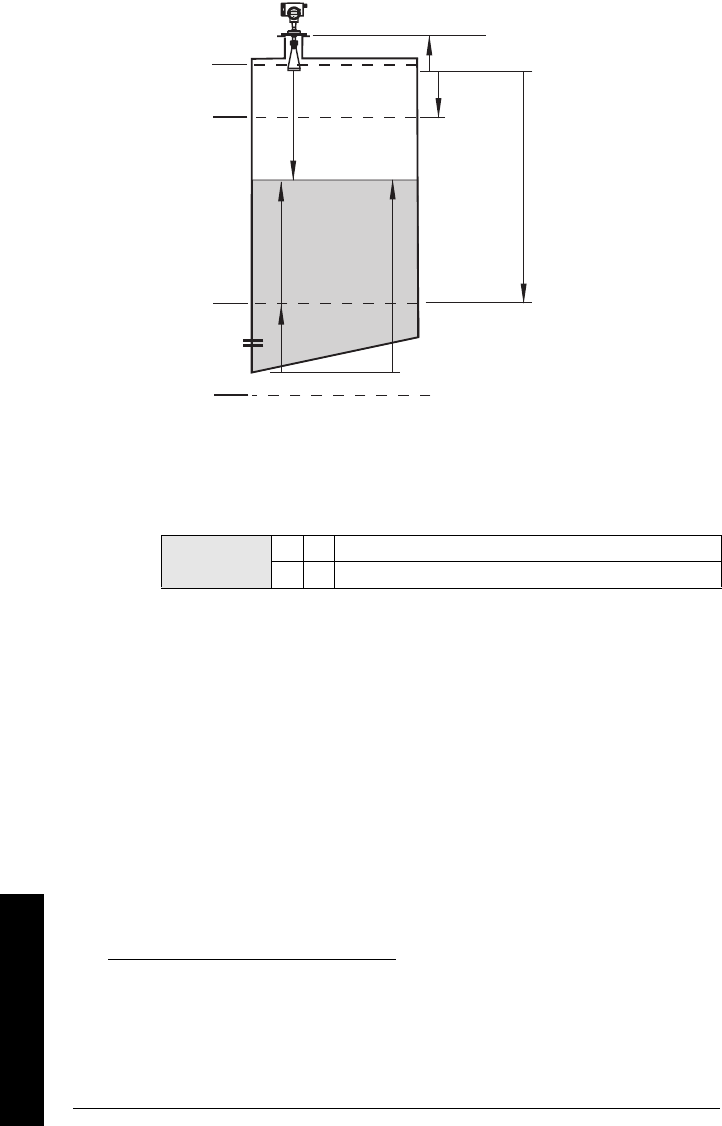
Page 63 SITRANS LR 460 – INSTRUCTION MANUAL 7ML19985JM01
mmmmm
Parameters
2.3. Sensor Calibration123
2.3.1. Sensor Units
Whatever units the sensor is measuring in.
2.3.2. Calibration Type
In "Dry" calibration, the user enters all four calibration values: High and Low Level
Points, and High and Low Calibration Points.
2.3.3. Low Calibration Pt.
Distance from Sensor Reference to Low Calibration Point (corresponding to Low
Level Point). Unit is defined in Sensor units. (In PDM, go to Device menu > Sensor
Calibration, then click on More Information, to see an illustration.)
2.3.4. High Calibration Pt.
Distance from Sensor Reference to HIgh Calibration Point (corresponding to High
Level Point). Unit is defined in Sensor units. (In PDM, go to Device menu > Sensor
Calibration, then click on More Information, to see an illustration.)
1. Sensor Reference Point: the point to which all of the above parameters are refer-
enced, which is the flange face.
2. Sensor Value: the value produced by the echo processing, which represents the dis-
tance from the Sensor Reference Point to the target.
3. Level Value: the level measured in level units.
Values 0*
"Dry" calibration
1"Wet" calibration (not recommended for SITRANS LR 460)
High Level Point
(default: 100%)
Sensor Reference Point1
(flange face)
Sensor Value2
Low Level Point
(default: 0%)
Level3
Level Offset
Secondary Value 1
Low Calibration
Point
Sensor Offset
High
Calibration
Point
tank reference point

7ML19985JM01 SITRANS LR 460 – INSTRUCTION MANUAL Page 64
mmmmm
Parameters
2.3.5. Unit (Level)
Selected engineering units for Level (PV).
• Referenced from Low Level Point (plus level offset, if any)
• Default %
• Can be any linear measurement
2.3.6. Low Level Point
The level when the material is at Low Calibration Point. The unit is defined in Level
units. (In PDM, go to Device menu > Sensor Calibration, then click on More
Information to see an illustration.)
2.3.7. High Level Point
The level when the material is at High Calibration Point. The unit is defined in Level
units. (In PDM, go to Device menu > Sensor Calibration, then click on More
Information to see an illustration.)
2.3.8. Level Offset
A constant offset that is added to Level to form either PV (Level or Volume) output.
The unit is defined in Level units.
2.3.9. Sensor Offset (default 0)
The offset from the Sensor’s reference point to the tank’s reference point. This is
a constant offset that is subtracted from the Sensor value. The unit is defined in
Sensor Units.
Compensates, for example if the sensor head is changed.
2.3.A. Temperature Units
Selects the engineering unit to be displayed with the value representing
temperature.
2.4. Measuring Limits
2.4.1. Min. Measured Value1
The minimum recorded Sensor value, defined in Sensor units.
2.4.2. Max. Measured Value1
The maximum recorded Sensor value, defined in Sensor units.
2.4.3. Min. Sensor Value
Defines the minimum usable value for the measuring range (physical limit of the
sensor) in Sensor units.
2.4.4. Max. Sensor Value
Defines the maximum usable value for the measuring range (physical limit of the
sensor) in Sensor units.
1. In PDM, open View menu, scroll down to Peak Values, and click Sensor tab.

Page 65 SITRANS LR 460 – INSTRUCTION MANUAL 7ML19985JM01
mmmmm
Parameters
2.4.5. Process Temperature Min.
The minimum recorded temperature of the internal electronics.
Open the menu View – Peak Values and select the tab Temperature. If necessary,
click on the reset button, and download to the device.
2.4.6. Process Temperature Max.
The maximum recorded temperature of the internal electronics.
Open the menu View – Peak Values and select the tab Temperature. If necessary,
click on the Reset button, and download to the device.
2.5. Detailed Setup
2.5.1. Failsafe
2.5.1.1. LOE (Loss of Echo) Timer
Amount of time, in minutes, that a Loss of Echo must persist, before the
device goes into Failsafe mode. See page 84 for more details.
2.5.2. Echo select
2.5.2.1. Algorithm
Selects the algorithm to be applied to the echo profile to extract the true
echo.
2.5.2.2. Confidence Threshold
Sets the minimum echo confidence that the echo must meet in order to
prevent a Loss of Echo condition and the expiration of the LOE timer. When
Echo Confidence exceeds the Confidence Threshold, the echo is
evaluated.
Use this feature when an incorrect material level is reported.
2.5.2.3. Echo Marker
The point on the selected echo from which the measured value is taken.
2.5.2.4. Shots
The number of echo profile samples averaged to produce a measurement.
2.5.2.5. Velocity
Effective propagation velocity in m/s.
Values Range: 0.00 to 720 (minutes)
Default:10
Values
12 * FFirst echo
3LLargest echo (reserved for SMPI service
personnel)
8bLF best of Largest or First echo (reserved for
SMPI service personnel)
Values Range: 0 to 99
Default: 5
Related
Parameters LOE Timer

7ML19985JM01 SITRANS LR 460 – INSTRUCTION MANUAL Page 66
mmmmm
Parameters
2.5.3. Echo Sampling
2.5.3.1. Sampling up1
Once echo is outside the window, a specified number of consecutive
echoes must appear above the echo locked onto, before measurement is
accepted as valid.
2.5.3.2. Sampling down1
Once echo is outside the window, a specified number of consecutive
echoes must appear below the echo locked onto, before measurement is
accepted as valid.
2.5.3.3. Window1
A "distance window" centered on the echo, used to derive the reading.
When a new measurement is in the window, the window is re-centered
and the reading is calculated (see Display before Auto False Echo
Suppression, page 69 for an illustration).
When the value is 0, the window is automatically calculated after each
measurement.
• For slower Measurement Response values, the window is narrow.
• For faster Measurement Response values, the window becomes
progressively wider.
2.5.3.4. Window Used1
2.5.4. Range
2.5.4.1. Near Range (LOW RANGE)
The range in front of the device (measured from the reference point
2
)
within which any echoes will be ignored. (This is sometimes referred to as
"Blanking" or "Dead Zone".)
1. This parameter is for use only by Siemens Milltronics service technicians.
Note: The echo lock window is stored as standard sample, but
displayed in the engineering units selected to display level. Any value
entered for the echo lock window will be rounded to the nearest
sample.
2. For the standard configuration reference point, see
SITRANS LR 460 Dimensions
on
page 10.
Values Range: 0 to 20 m
Default: 0.4 m

Page 67 SITRANS LR 460 – INSTRUCTION MANUAL 7ML19985JM01
mmmmm
Parameters
2.5.4.2. Far Range (HI RANGE)
Maximum distance from the reference point
2
, within which an echo
should be considered valid.
Echo Profile
Echo Confidence
Measures echo reliability. It displays the echo confidence of the
measurement echo from the last shot. Confidence Threshold defines the
minimum criterion for echo confidence.
Open the menu View – Profile.
Echo Strength
Displays the absolute strength (in dB above 1 µV rms) of the echo selected
as the measurement echo.
Open the menu View – Profile.
Noise Average
Displays the average ambient noise (in dB above 1 µV rms) of a noise
profile, as x.y. Noise level is a combination of transient noise and receiving
circuitry. After a measurement, the values from the previous noise shot
will be displayed.
Open the menu View – Noise.
Noise Peak
Displays the peak ambient noise (in dB above 1 µV rms).
Open the menu View – Noise.
Noise Minimum
Displays the minimum ambient noise (in dB above 1 µV rms).
Open the menu View – Noise.
Note: Far Range can extend beyond the bottom of the tank.
Values Range: 0 to 20 m
Default: Low Calibration Point
Values (view only) 0 to 99
---- Shot not used
Related
Parameters Confidence Threshold
Values (view only) –20 to 99

7ML19985JM01 SITRANS LR 460 – INSTRUCTION MANUAL Page 68
mmmmm
Parameters
2.5.5. TVT (Auto False Echo Suppression) setup
First SITRANS LR 460 learns the echo profile. Then the learned profile, or part of
the learned profile, is used to screen out false echoes.
2.5.5.1. TVT Hover Level1
Defines in percent how high the TVT (Time Varying Threshold) curve is
placed above the echo profile, with respect to largest echo. When
SITRANS LR 460 is located in the center of the vessel, lower this
parameter to prevent multiple echo detections.
2.5.5.6. Auto False Echo Suppression1
Enables a ’learned’ TVT curve to be used in place of the default TVT curve.
Use this feature to ignore false echoes before the material echo. Set
Range (Auto False Echo Suppression Distance) first.
a. Rotate the instrument for best signal (lower false-echo amplitude).
b. Go to Range, and set the value (see details below).
c. Open the menu Device – Auto False Echo Suppression and select
the option to change it.
d. Select Learn. The device will automatically revert to On (Use
Learned TVT) after a few seconds.
2.5.5.7. Range (Auto False Echo Suppression Distance)
Defines the endpoint of the Learned TVT distance.
a. Go to Input > Detailed Setup > TVT Setup > Range.
b. Determine the actual distance from the antenna reference point to
the material surface.
c. Subtract 0.5 m (20") from this distance, and enter the result.
Note: The Auto False Echo Suppression parameters are for authorized Siemens
Milltronics Service personnel or technicians familiar with Siemens Milltronics
echo processing techniques. View the echo profile first, before attempting to
modify these parameters.
1. For an illustration, see
Display before Auto False Echo Suppression
and
Example after
Auto False Echo Suppression
, page 69.
Values Range: 0 to 100%
Default: 40%
Values
0Off
1Enable Auto False Echo Suppression
2"Learn" the TVT curve
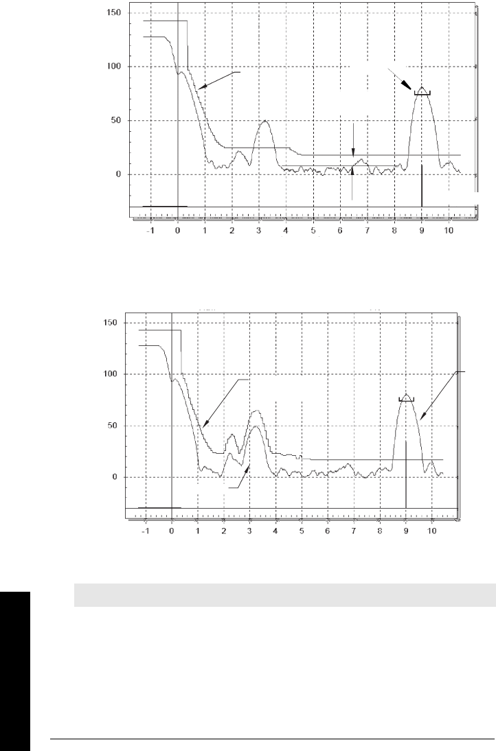
Page 69 SITRANS LR 460 – INSTRUCTION MANUAL 7ML19985JM01
mmmmm
Parameters
2.5.5.8. Shaper Mode
Adjusts the TVT curve at a specified range.
Curves to be updated to SITRANS LR 460 curves.
Display before Auto False Echo Suppression
Default TVT
TVT
Hover Level
Level (db)
Distance (meters)
Echo Marker
Window
Example after Auto False Echo Suppression
TVT curve
(Learned)
Liquid
level
False echo
Distance (meters)
Level (db)
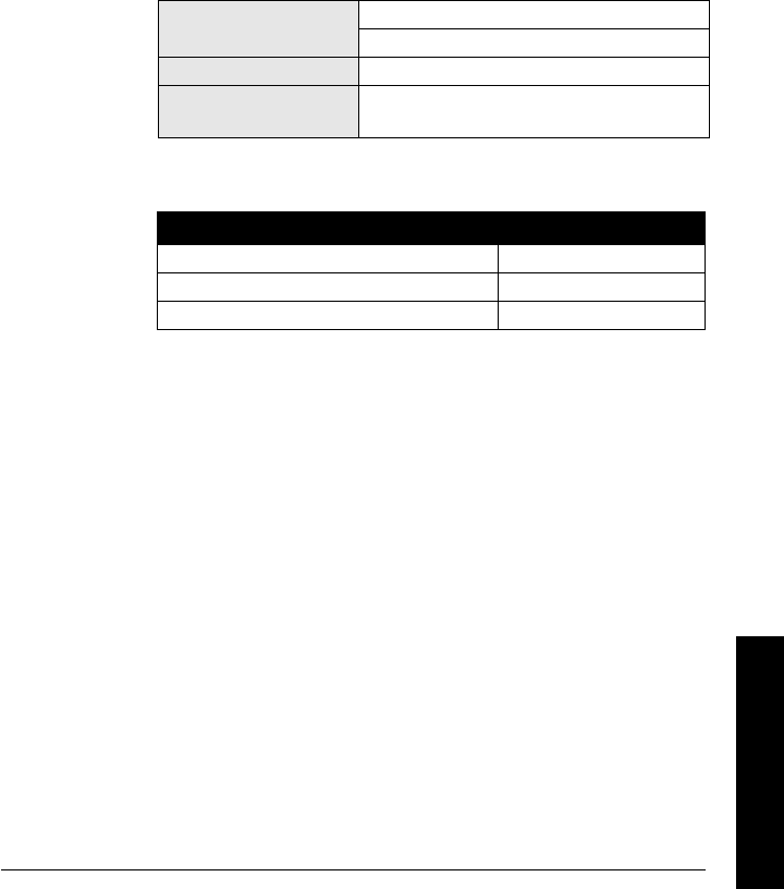
7ML19985JM01 SITRANS LR 460 – INSTRUCTION MANUAL Page 70
mmmmm
Parameters
2.5.6. TVT shaper
A breakpoint on the TVT curve, normalized to 0.
2.5.6.1. Shaper A (1-9)
2.5.6.2. Shaper B (10-18)
2.5.6.3. Shaper C (19-27)
2.5.6.4. Shaper D (28-36)
2.5.6.5. Shaper E (37 - 40)
2.5.7. Rate
2.5.7.1. Fill Rate
Defines the maximum rate at which the reported sensor value is allowed
to increase.Allows you to further adjust the LR 460 response to increases
in the actual material level (or an advance to a higher Failsafe Material
Level, P071). Fill Rate is automatically updated whenever Response Rate
is altered.
Enter a value slightly greater than the maximum vessel-filling rate, in
Sensor Units per minute.
Values Range: 0.0000 to 99999 m / min.
Factory setting: 0.1
Altered by Response Rate
Related Unit (Level)
High Level Point
Handheld programmer Value Meters/Minute
10.1
21
310

Page 71 SITRANS LR 460 – INSTRUCTION MANUAL 7ML19985JM01
mmmmm
Parameters
2.5.7.2. Empty rate
Defines the maximum rate at which the reported sensor value is allowed
to decrease.Adjusts the LR 460 response to decreases in the actual
material level. Empty Rate is automatically updated whenever Response
Rate is altered.
Enter a value slightly greater than the vessel’s maximum emptying rate, in
Sensor Units per minute.
2.5.8. Transducer Block (TB) Values (for diagnostic purposes)
2.5.8.1. PV
The value for level, or volume (if volume conversion is selected).
Open the menu View – Display, and select the tab Measure Valued
(Secondary Values).
2.5.8.2. SV1
The value for level.
Open the menu View – Display, and select the tab Measure Valued
(Secondary Values).
2.5.8.3. SV2
The value for distance.
Open the menu View – Display, and select the tab Measure Valued
(Secondary Values).
Values Range: 0.0000 to 99999 m / min.
Factory setting: 0.1
Altered by Response Rate
Related Units (Level)
High Level Point
Handheld programmer Value Meters/Minute
10.1
21
310

7ML19985JM01 SITRANS LR 460 – INSTRUCTION MANUAL Page 72
mmmmm
Parameters
3. Output
3.1. AIFB1
Static Revision No.
The revision level of the static data associated with Analog Input Function Block 1.
The Static Revision No. is updated whenever a standard profile configuration
parameter is changed.
3.1.1. Target Mode
Used to request an operating mode from the Function Block.
Open the menu Device – Simulation, go to Function Block – AIFB1 or 2, click on
the tab Simulation Output, and select a target mode. Then click on the tab
Simulation (Measured Value), and enable or disable Simulation.
3.1.2. Unit
Engineering unit to be displayed with the output value.
3.1.3. Filter Time Constant
The time constant for the damping filter. The engineering unit is always in
seconds. (This is an exponential filter: when a change occurs at the input, the
output will be at 63.2% of the change in one time constant, and will be at full
change after 5 time constants.)
3.1.4. Function
Used to select between the different level block outputs (Volume/Level, Level,
Distance in Sensor units, Distance in Level units).
3.1.5. Batch Information
These 4 parameters are intended to be used in Batch Applications conforming to
IEC 61512 Part 1 (ISA S88). Other applications do not require these values, which
are only stored in the Function Block.
3.1.5.1. Batch ID
Identifies a certain batch to allow assignment of equipment-related
information (for example faults, alarms) to the batch.
3.1.5.2. Batch Unit
Identifies the active Control Recipe Unit Procedure or the related Unit (for
example, reactor, centrifuge, drier).
3.1.5.3. Batch operation
Identifies the active Control Recipe Operation.
3.1.5.4. Batch Phase
Identifies the active Control Recipe Phase.
Values
128 Out of Service (O/S)
16 Manual Mode (MAN)
8Automatic Mode (AUTO)

Page 73 SITRANS LR 460 – INSTRUCTION MANUAL 7ML19985JM01
mmmmm
Parameters
3.1.6. Process Value Scale
3.1.6.1. Lower Value
Defines the operational lower range value of the input value (Process
Value Scale) in engineering units. Process Value Scale normalizes the
input value to a customer-defined range.
3.1.6.2. Upper Value
Defines the operational upper range value of the input value (Process
Value Scale) in engineering units. Process Value Scale normalizes the
input value to a customer-defined range.
3.1.7. Output Scale
Scales the Process Variable. The function block parameter OUT SCALE
contains the values of the lower limit and upper limit effective range.
3.1.7.1. Lower Value
Defines the operational lower range value of the output value in
engineering units.
3.1.7.2. Upper Value
Defines the operational upper range value of the output value in
engineering units.
3.1.8. Output Limits
3.1.8.1. Lower Limit Alarm
The setting for the lower alarm limit in engineering units.
3.1.8.2. Lower Limit Warning
The setting for the lower warning limit in engineering units.
3.1.8.3. Upper Limit Warning
The setting for the upper warning limit in engineering units.
3.1.8.4. Upper Limit Alarm
The setting for the upper alarm limit in engineering units
0
1
2
3
4
5
6
12345
Process Value Scale (typical
Input (0 to 100%)
Output Scale
Out (AIFB1 or AIFB2 Out)

7ML19985JM01 SITRANS LR 460 – INSTRUCTION MANUAL Page 74
mmmmm
Parameters
3.1.8.5. Limit Hysteresis
Hysteresis is used to adjust the sensitivity of the trigger for alarm
messages. It is used to compensate when a process variable fluctuates
around the same value as a limit. A high level alarm occurs when a value
exceeds an upper limit. The alarm’s status remains true until the value
drops below the limit minus the alarm hysteresis. The directions are
reversed for low limit detection.
Enter a value for the hysteresis here, to be used for all warnings and
alarms. The units are the same as the output value scale.
3.1.8.6. Min Out
Min Out is a minimum peak indicator for the AIFB output values.
3.1.8.7. Max Out
Max Out is a maximum peak indicator for the AIFB output values.
3.1.9. Failsafe Mode
3.1.9.1. Failsafe Mode
Failsafe Mode occurs if the status of the input value is bad, or if the device
has been put into Failsafe mode using Simulation. One of three options can
be selected for the material level to be reported when the LOE timer
expires.
3.1.9.2. Failsafe Value
(Accessible in PDM only after 0 is selected in Failsafe Mode).
User-defined default value for the OUT parameter, if sensor or sensor
electronic fault is detected. Units are the same as the OUT value.
3.1.A. Human Interface
3.1.A.1. Decimal Point
The number of digits to display after the decimal point. (The LCD is limited
to displaying three decimal places.)
Out unit text
If the code list does not contain a desired unit for the OUT parameter, (see
General Requirement) you can write the specific text in this parameter.
3.2. AIFB2
(See AIFB1: the parameters for AIFB2 are identical.)
Handheld
programmer
Values
Material level to be reported
0Default value used as output value.
1* Store last valid output value.
2Calculated output value is incorrect.

Page 75 SITRANS LR 460 – INSTRUCTION MANUAL 7ML19985JM01
mmmmm
Parameters
Certificates and Approvals
Device Certification
5. Maintenance settings
5.1. Remaining Device Lifetime
5.1.1. Total Device Operating Time
5.1.2. Remaining Device Lifetime
5.1.3. Maintenance Required Limit
5.1.4. Maintenance Demanded Limit
5.1.5. Maintenance Alert Activation
5.1.6. Total Expected Device Life
5.1.7. Units
5.1.8. Maintenance Status
5.1.9. Acknowledge Status
5.1.10. Acknowledge
5.2. Remaining Sensor Lifetime
5.2.1. Total Sensor Operating Time
5.2.2. Remaining Sensor Lifetime
5.2.3. Maintenance Required Limit
5.2.4. Maintenance Demanded Limit
5.2.5. Maintenance Alert Activation
5.2.6. Total Expected Sensor Life
5.2.7. Units
5.2.8. Maintenance Status
5.2.9. Acknowledge Status
5.2.10. Acknowledge
5.3. Service Interval
5.3.1. Time Elapsed Since Last Service
5.3.2. Maintenance Required Limit
5.3.3. Maintenance Demanded Limit
5.3.4. Maintenance Alert Activation
5.3.5. Total Service Interval
5.3.6. Units
5.3.7. Maintenance Status
5.3.8. Acknowledge Status
5.3.9. Acknowledge

7ML19985JM01 SITRANS LR 460 – INSTRUCTION MANUAL Page 76
mmmmm
Parameters
5.4. Calibration Interval
5.4.1. Time Elapsed Since Last Calibration
5.4.2. Maintenance Required Limit
5.4.3. Maintenance Demanded Limit
5.4.4. Maintenance Alert Activation
5.4.5. Total Calibration Interval
5.4.6. Units
5.4.7. Maintenance Status
5.4.8. Acknowledge Status
5.4.9. Acknowledge
6. Condensed Status Setup
6.1. Condensed Status Mode
Event Index
Event Status
Event Diagnosis
6.1.1. Loss of Echo S0 (Status; Diagnosis)
6.1.2. Cable Fault S1 (Status; Diagnosis)
6.1.3. No Tech Power S2 (Status; Diagnosis)
6.1.4. Device Lifetime Maintenance Required Limit S3 (Status; Diagnosis)
6.1.5. Device Lifetime Maintenance Demanded Limit S4 (Status; Diagnosis)
6.1.7. Sensor Lifetime Maintenance Required Limit S6 (Status; Diagnosis)
6.1.8. Sensor Lifetime Maintenance Demanded Limit S7 (Status; Diagnosis)
6.1.9. Device Service Maintenance Required Limit S8 (Status; Diagnosis)
6.1.10. Device Service Maintenance Demanded Limit S9 (Status; Diagnosis)
6.1.11. LTB Scale S10 (Status; Diagnosis)
6.1.12. Internal Temp Sensor S11 (Status; Diagnosis)
6.1.13. Internal Temp High S12 (Status; Diagnosis)
6.1.15. AIFB1 PV Range S14 (Status; Diagnosis)
6.1.16. AIFB2 PV Range S15 (Status; Diagnosis)
6.1.18. Calibration Schedule Maintenance Required Limit S17 (Status; Diagnosis)
6.1.19. Calibration Schedule Maintenance Demanded Limit S18 (Status; Diagnosis)
6.1.29. Memory RAM S28 (Status; Diagnosis)
6.1.30. Memory EEPROM S29 (Status; Diagnosis)
6.1.31. Memory EEPROM Flags S30 (Status; Diagnosis)
6.1.32. Memory Flash S31 (Status; Diagnosis)
6.1.33. Ident Violation S32 (Status; Diagnosis)
6.1.34. Internal Temperature Calibration S33 (Status; Diagnosis)

Page 81 SITRANS LR 460 – INSTRUCTION MANUAL 7ML19985JM01
mmmmm
Parameters

7ML19985JM01 SITRANS LR 460 – INSTRUCTION MANUAL Page 82
mmmmm
F: Technical Reference
Appendix B: Technical Reference
Principles of Operation
SITRANS LR 460 is a long range FMCW (Frequency Modulated Continuous Wave) radar
transmitter. Radar level measurement uses the time of flight principle to determine
distance to a material surface. The transmit time is directly proportional to the distance to
the material.
FMCW radar transmits a continuous wave. The frequency of the wave is constantly
increasing: this is known as the sweep. By the time the first part of the wave has been
reflected off the target and returned to the device, the part of the wave that is just being
emitted is at a higher frequency. The difference in frequency between the transmitted and
received signals is proportional to time of flight.
Electromagnetic wave propagation is virtually unaffected by temperature or pressure
changes, or by changes in the vapor or dust levels inside a vessel.
SITRANS LR 460 consists of an enclosed electronic component coupled to an antenna
and process connection. The electronic component generates an electromagnetic signal
from 24.2 GHz to 25.2 GHz that is directed to the antenna.
The signal is emitted from the antenna, and the reflected echoes are digitally converted
to an echo profile. The profile is analyzed to determine the distance from the material
surface to the reference point on the instrument. This distance is used as a basis for the
display of material level and output.
Measurement Response
The measurement response (response rate) limits the maximum rate at which the
display and output respond to changes in the measurement. Once the real process fill/
empty rate (m/s) is established, a response rate can be selected that is slightly higher
than the application rate. The response rate automatically adjusts the filters that affect
the output response rate.
There are three preset options: slow, medium, and fast.
If none of the preset options is satisfactory, the filters can be adjusted individually.
Related
Parameters
Response
Rate
LOE Timer
(minutes) Fill Rate Empty
Rate
Echo
Lock
Values
1* slow 100 0.1 m/minute 0.1 m/minute
2material
agitator
2medium 10 1 m/minute 1 m/minute
3fast 1 10 m/minute 10 m/minute

Page 83 SITRANS LR 460 – INSTRUCTION MANUAL 7ML19985JM01
mmmmm
F: Technical Reference
Echo Lock
When the echoes are received, the relevant echo algorithm is applied to determine the
true material echo. If the selected echo is within the window, the window is then
centered about the echo. Otherwise the window widens with each successive shot until
the selected echo is within the window, which then returns to its normal width.
Echo Lock selects the measurement verification process:
• When Echo Lock is Off, SITRANS LR 460 responds immediately to a new
measurement (within the restrictions set by the Maximum Fill / Empty Rate).
However, measurement reliability is affected.
• When Maximum Verification or Material Agitator is selected, a new measurement
outside the Echo Lock Window must meet the sampling criteria.
• When Total Lock is selected, Echo Lock Window is pre-set to 0, and the window is
automatically calculated after each measurement.
Loss of Echo (LOE)
A loss of echo (LOE) occurs when the calculated measurement is judged to be unreliable
because the echo confidence value has dropped below the echo confidence threshold.
The LOE timer starts running, and if the LOE condition persists beyond ten minutes (the
time limit set by the LOE timer) the Unreliable Echo indicator replaces the Reliable Echo
indicator.
Reliable Echo indicator Unreliable Echo indicator .
While LOE is pending the x flashes, alternating with the two horizontal bars. When LOE
becomes active, the x becomes solid and the auxiliary display shows fault code S: 0.
Upon receiving a reliable echo, the loss of echo condition is aborted, the Reliable Echo
indicator reappears, and the reading returns to the current level.
Values
0Off
1Maximum Verification
2*
Material Agitator
3Tot al L ock

7ML19985JM01 SITRANS LR 460 – INSTRUCTION MANUAL Page 84
mmmmm
F: Technical Reference
LOE Timer
The LOE timer determines the time (in minutes) to elapse after the last valid reading
before Failsafe mode is activated. When the LOE timer expires, the material level to be
reported is determined by Failsafe Mode.
Failsafe Mode
Failsafe mode may be triggered by a loss of echo, a bad configuration, or certain device
faults. You can select can select one of three possible values to be reported when a
Failsafe mode occurs:
• Default value (Failsafe value) used as output value.
• Store last valid output value.
• Calculated output value is incorrect.
Failsafe value
Failsafe value is a user-defined value. This allows you to enter the safest output value for
your application.
For example, you may want to select a user-defined high value, to prevent an overfill
(Failsafe Hi). Or you may want to select a low value, to protect a pump from operating dry
(Failsafe Lo).
False Echoes
False echoes can appear during the receive cycle. They are often created by internal
impediments like a ladder rung, and are usually indicated by an incorrect high level
reading.
Near Range (Blanking)
Near Range allows you to set a distance in front of the antenna, within which any echoes
will be ignored. But Auto False-Echo Suppression is generally recommended in
preference to using Near Range.
Auto False-Echo Suppression
The TVT adjustment parameters allow you to set a TVT (Time Varying Threshold) curve, so
that SITRANS LR 460 will ignore false echoes.
The default TVT curve hovers above the echo profile, and effectively screens out small
false echoes. But if an obstruction is causing a large echo before the material level echo,
that echo will rise above the default TVT curve. You can use Auto False-Echo Suppression
to filter it out. If possible, rotate the instrument before using Auto False-Echo
Suppression, to lower the amplitude of false echoes.

Page 85 SITRANS LR 460 – INSTRUCTION MANUAL 7ML19985JM01
mmmmm
F: Technical Reference
When you set Auto False-Echo Suppression to Learn, the instrument learns the echo
profile at that moment1. Then it uses the learned profile instead of the default TVT curve,
for the distance set in Auto False Echo Suppression Distance. The learned profile
(learned TVT curve) follows the echo profile, so that no large false echoes rise above the
learned TVT curve. From the end of the Auto False-Echo Suppression Distance, the
default TVT curve is used. The material level echo rises above this, and is selected as the
true echo.
See page 69 for examples of the echo profile before and after using Auto False-Echo
Suppression.
1. Set Auto False-Echo Suppression to Learn when the material level is substantially lower than
process full level (ideally when the tank is empty or almost empty).
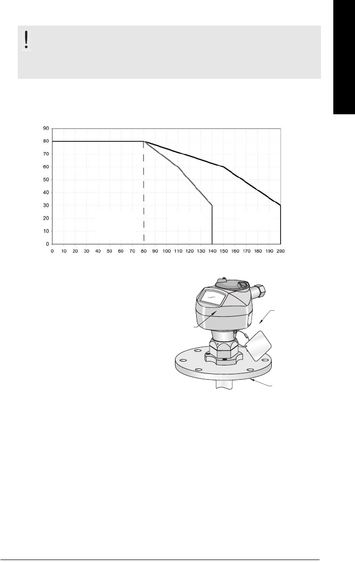
7ML19985JM01 SITRANS LR 460 – INSTRUCTION MANUAL Page 86
mmmmm
F: Technical Reference
Maximum Process Temperature Chart
.
Where the chart does not apply, please use your own judgement regarding the use of
SITRANS LR 200. Open the menu View – Peak Values, and click on the temperature tab to see
the maximum and minimum temperatures recorded. These can be used to determine whether
the installation needs to be redesigned.
For example, if the internal temperature exceeds the maximum allowable limit, a sun shield or a
longer nozzle may be required.The peak temperatures indicate the extent of change required to
the installation in order to provide a reliable thermal-operating zone for SITRANS LR 200.
WARNING: Internal temperature must not exceed 80 oC (176 oF).
Note: The chart below is for guidance only. Information to be updated to SITRANS LR
460 information.
Maximum Flange and Process Temperatures versus Allowable Ambient for
Polypropylene Rod or Flange Adaptor versions of SITRANS LR 200
flange
temperature
process
temperature
Ambient Temperature (oC)
Process Flange Surface Temperature (oC)
polypropylene
rod
temperature
(no flange)
• The chart does not represent every
possible process connection
arrangement. For example, it will NOT
apply if you are mounting the LR 200 on
a nozzle greater than 8” nominal, or
directly on a metallic vessel surface.
• The chart does not take into
consideration heating from direct
sunshine exposure.
ambient
temperature
process
temperature
internal
enclosure
temperature

Page 87 SITRANS LR 460 – INSTRUCTION MANUAL 7ML19985JM01
mmmmm
G: Troubleshooting
Appendix C: Troubleshooting
1. Check the following:
• There is power at the instrument.
• The LCD shows the relevant data.
• Check whether any fault codes are being displayed (see
Acyclic Extended
Diagnostics (General Fault Codes)
on page 51 for a detailed list).
• The device can be programmed using the handheld programmer.
2. Verify that the wiring connections are correct.
3. Check the PROFIBUS address and make sure all devices are at unique PROFIBUS
addresses.
4. If the device cannot be programmed via the handheld programmer, make sure local
operation is enabled. See
Local operation enable
on page 26. Also make sure that
Write Locking is Off. See
Write locking
on page 34.
5. If you try to set a SITRANS LR 460 parameter via remote communications, but the
parameter remains unchanged, make sure remote operation is enabled. See
Remote operation enable
on page 26. Also make sure that Write Locking is Off. See
Write locking
on page 27.
6. If you continue to experience problems, go to our website at www.siemens.com/
processautomation, and check the FAQs for SITRANS LR 200, or contact your
Siemens Milltronics representative.
7. If the PLC value equals the display value, but does not correspond to actual material
level, either:
• scaling in AIFB1 is incorrect, or
• High Calibration Point is incorrectly entered, or
• the wrong echo is being selected.
8. If the PLC value is not equal to the displayed value (regardless of actual material
level), either:
• you may not be looking at the right spot in the PLC, or
• you may have programmed scaling into the PLC, instead of leaving all scaling to
be performed in the LR 200, or
• the PLC may not be communicating with the LR 460. Check the network to verify
that you are communicating.

7ML19985JM01 SITRANS LR 460 – INSTRUCTION MANUAL Page 88
mmmmm
G: Troubleshooting
General Fault Codes
Note: Some faults cause the device to go to Failsafe mode (Fault 52). These are
indicated with an asterisk (*).
LCD
display Meaning Corrective Action Byte Bit
S:0
The device was unable to get
a measurement within the
Failsafe timer period.
Possible causes: faulty
installation, material
buildup,and/or presence of
foam.
Ensure installation details
are correct. Ensure no
material buildup. Adjust
process conditions to
minimize foaming. If problem
persists, contact your local
Siemens representative.
0
0
S:2 Internal electronics failure.
Reset power. If fault
persists,contact your local
Siemens representative:
repair required.
2
S:3
Device is nearing its lifetime
limit according to the value
set in Maintenance Required
Limit.
Replacement is
recommended. 3
S:4
Device is nearing its lifetime
limit according to the value
set in Maintenance
Demanded Limit.
Replacement is
recommended. 4
S:6
Sensor is nearing its lifetime
limit according to the value
set in Maintenance Required
Limit.
Replacement is
recommended. 6
S:7
Sensor is nearing its lifetime
limit according to the value
set in Maintenance
Demanded Limit.
Replacement is
recommended. 7

Page 89 SITRANS LR 460 – INSTRUCTION MANUAL 7ML19985JM01
mmmmm
G: Troubleshooting
S:8
Service interval as defined in
Maintenance Required Limit
has expired.
Perform service.
1
0
S:9
Service interval as defined in
Maintenance Demanded
Limit has expired.
Perform service.
1
S:10
Input parameters High
Calibration Point and Low
Calibration Point are the
same.
Check calibration settings of
device. Ensure settings for
High Calibration Point and
Low Calibration Point are
different.
3
S:11 Internal temperature sensor
failure.
Return the device to the
factory. 4
S:12 *
Internal temperature of the
device has exceeded
specifications: it is operating
outside its temperature
range.
Lower the ambient
temperature enough to cool
the device.
Fault code will persist until a
manual reset is performed
using PDM or the LCD
interface.
5
S:14
Upper and lower input values
(Process Value Scale) for
AIFB1 are the same.
Check configuration for
AIFB1. Ensure that Upper
Value and Lower Value
(Process Value Scale) are not
the same.
6
S:15
Upper and lower input values
(Process Value Scale) for
AIFB2 are the same.
Check configuration for
AIFB2. Ensure that Upper
Value and Lower Value
(Process Value Scale) are not
the same.
7
LCD
display Meaning (cont’d) Corrective Action Byte
(cont’d) Bit

7ML19985JM01 SITRANS LR 460 – INSTRUCTION MANUAL Page 90
mmmmm
G: Troubleshooting
S: 17
Calibration interval as
defined in Maintenance
Required Limit has expired.
Perform calibration.
2
1
S: 18
Calibration interval as
defined in Maintenance
Demanded Limit has expired.
Perform calibration. 2
S:28 Internal device failure caused
by a memory error.
Repair required: contact your
local Siemens
representative.
3
4
S:29 EEPROM damaged.
Repair required: contact your
local Siemens
representative.
5
S:30 EEPROM corrupt.
Reset power. If error persists,
contact your local Siemens
representative.
6
S:31 Flash error.
Repair required: contact your
local Siemens
representative.
7
S: 32
The IDENT number used in
communications, and number
selected by the Ident Number
Selector do not correspond.
Ensure value of the Ident
number selector is correct
for the network
configuration. If it is correct,
the device needs to be re-
parameterized by the PLC. 4
0
S:33
Factory calibration for the
internal temperature sensor
has been lost.
Repair required: contact your
local Siemens
representative.
1
LCD
display Meaning (cont’d) Corrective Action Byte
(cont’d) Bit

Page 91 SITRANS LR 460 – INSTRUCTION MANUAL 7ML19985JM01
mmmmm
G: Troubleshooting
S:34 Factory calibration for the
device has been lost.
Repair required: contact your
local Siemens
representative.
4
2
S:35 Factory calibration for the
device has been lost.
Repair required: contact your
local Siemens
representative.
3
S:36 Unable to start microwave
module.
Reset power. If error persists,
contact your local Siemens
representative.
4
S:37 Unable to collect profile.
Repair required: contact your
local Siemens
representative.
5
S:38
Microwave module hardware
failure: unable to calculate
distance measurement.
Repair required: contact your
local Siemens
representative.
6
LCD
display Meaning (cont’d) Corrective Action Byte
(cont’d) Bit

7ML19985JM01 SITRANS LR 460 – INSTRUCTION MANUAL Page 92
mmmmm
H: Maintenance
Appendix D: Maintenance
SITRANS LR 460 requires no maintenance or cleaning under normal operating conditions.
Under severe operating conditions, the antenna may require periodic cleaning. If
cleaning becomes necessary:
• Note the antenna material and the process medium, and select a cleaning
solution that will not react adversely with either.
• Remove the instrument from service and wipe the antenna clean using a cloth
and suitable cleaning solution.
Unit Repair and Excluded Liability
All changes and repairs must be done by qualified personnel, and applicable safety
regulations must be followed. Please note the following:
• The user is responsible for all changes and repairs made to the device.
• All new components must be provided by Siemens Milltronics Process Instruments
Inc.
• Restrict repair to faulty components only.
• Do not re-use faulty components.

Page 93 SITRANS LR 200 (HART) – INSTRUCTION MANUAL 7ML19985FN04
mmmmm
N: sorftware rev.
Appendix E: Software Revision History
Soft-
ware
Rev.
DD
Rev. Date Changes
•
•
•
•
•
•

7ML19985JM01 SITRANS LR 460 – INSTRUCTION MANUAL Page 94
mmmmm
Glossary
Glossary
accuracy: degree of conformity of a measure to a standard or a true value.
agitator: mechanical apparatus for mixing or aerating. A device for creating turbulence.
algorithm: a prescribed set of well-defined rules or processes for the solution of a problem in a
finite number of steps.
ambient temperature: the temperature of the surrounding air that comes in contact with the
enclosure of the device.
antenna: an aerial which sends out and receives a signal in a specific direction. There are four
basic types of antenna in radar level measurement, horn, parabolic, rod, and waveguide.
attenuation: a term used to denote a decrease in signal magnitude in transmission from one
point to another. Attenuation may be expressed as a scalar ratio of the input magnitude to
the output magnitude or in decibels.
Auto False-Echo Suppression: a technique used to adjust the level of a TVT curve to avoid the
reading of false echoes. (See TVT.)
Auto False-Echo Suppression Distance: defines the endpoint of the TVT distance. (See TVT.)
This is used in conjunction with auto false echo suppression.
beam angle: the angle diametrically subtended by the one-half power limits (-3 dB) of the
sound beam.
beam spreading: the divergence of a beam as it travels through a medium.
blanking: a blind zone extending away from the reference point plus any additional shield
length.The instrument is programmed to ignore this zone.
capacitance: the property of a system of conductors and dielectrics that permits the storage of
electricity when potential differences exist between the conductors. Its value is
expressed as the ratio of a quantity of electricity to a potential difference, and the unit is a
Farad.

Page 95 SITRANS LR 460 – INSTRUCTION MANUAL 7ML19985JM01
mmmmm
Glossary
confidence: describes the quality of an echo. HIgher values represent higher quality.
Confidence threshold defines the minimum value.
damping: term applied to the performance of an instrument to denote the manner in which the
measurement settles to its steady indication after a change in the value of the level.
dB (decibel): a unit used to measure the amplitude of signals.
derating: to decrease a rating suitable for normal conditions according to guidelines specified
for different conditions.
dielectric: a nonconductor of direct electric current.1
dielectric constant (DK): the ability of a dielectric to store electrical potential energy under the
influence of an electric field. Also known as Relative Permitivity. An increase in the
dielectric constant is directly proportional to an increase in signal amplitude. The value is
usually given relative to a vacuum /dry air: the dielectric constant of air is 11.
echo: a signal that has been reflected with sufficient magnitude and delay to be perceived in
some manner as a signal distinct from that directly transmitted. Echoes are frequently
measured in decibels relative to the directly transmitted signal.
echo confidence: the recognition of the validity of the echo. A measure of echo reliability.
Echo Lock Window: a window centered on an echo in order to locate and display the echo’s
position and true reading. Echoes outside the window are not immediately processed.
Echo Marker: a marker that points to the processed echo.
Echo Processing: the process by which the radar unit determines echoes.
Echo Strength: describes the strength of the selected echo in dB above 1 µV rms.
Echo Profile: a graphical display of a processed echo.
emission cone: the extension of the antenna’s angle
false echo: any echo which is not the echo from the desired target. Generally, false echoes are
created by vessel obstructions.
1. Many conductive liquids/electrolytes exhibit dielectric properties; the relative
dielectric constant of water is 80.

7ML19985JM01 SITRANS LR 460 – INSTRUCTION MANUAL Page 96
mmmmm
Glossary
frequency: the number of periods occurring per unit time. Frequency may be stated in cycles
per second.
hertz (Hz): unit of frequency, one cycle per second. 1 Gigahertz (GHz) is equal to 109 Hz.
horn antenna: a conical, horn-shaped antenna which focuses microwave signals. The larger
the horn diameter, the more focused the radar beam.
inductance: the property of an electric circuit by virtue of which a varying current induces an
electromotive force in that circuit or in a neighboring circuit. The unit is a Henry.
microwaves: the term for the electromagnetic frequencies occupying the portion of the radio
frequency spectrum from 1 GHz to 300 GHz.
multiple echoes: secondary echoes that appear as double, triple, or quadruple echoes in the
distance from the target echo.
Near Blanking: see Blanking
nozzle: a length of pipe mounted onto a vessel that supports the flange.
parameters: in programming, variables that are given constant values for specific purposes or
processes.
polarization: the property of a radiated electromagnetic wave describing the time-varying
direction and amplitude of the electric field vector.
polarization error: the error arising from the transmission or reception of an electromagnetic
wave having a polarization other than that intended for the system.
PROFIBUS PA: one of the PROFIBUS family of protocols, specifically tailored for the needs of
process industries (PA = Process Automation).
propagation factor (pf): where the maximum velocity is 1.0, pf is a value that represents a
reduction in propagation velocity as a result of the wave travelling through a pipe or
medium.
pulse radar: a radar type that directly measures distance using short microwave pulses.
Distance is determined by the return transmit time.

Page 97 SITRANS LR 460 – INSTRUCTION MANUAL 7ML19985JM01
mmmmm
Glossary
radar: radar is an acronym for RAdio Detection And Ranging. A device that radiates
electromagnetic waves and utilizes the reflection of such waves from distant objects to
determine their existence or position.
range: distance between a transmitter and a target.
range extension: the distance below the zero percent or empty point in a vessel.
relative permittivity: see dielectric constant.
repeatability: the closeness of agreement among repeated measurements of the same
variable under the same conditions.
shot: one transmit pulse or measurement.
speed of light: the speed of electromagnetic waves (including microwave and light in free
space. Light speed is a constant 299,792,458 meters per second.
stillpipe: a pipe that is mounted inside a vessel parallel to the vessel wall, and is open to the
vessel at the bottom.
stilling-well: see stillpipe.
two wire radar: a low-energy radar. Can be loop powered, analog, intrinsically safe, or a digital
(BUS) transmitter.
TVT (time varying threshold): a time-varying curve that determines the threshold level above
which echoes are determined to be valid.
waveguide antenna: a hollow, metallic tube that transmits a microwave signal to the product
target.

7ML19985JM01 SITRANS LR 460 – INSTRUCTION MANUAL Page 98
mmmmm
Index
Index
A
abbreviations
list 3
accuracy 5
acyclic diagnostics
fault codes 50
address 58
agitator blade detection
avoiding 62
agitators 62
approvals 9
Auto False-Echo Suppression 84
B
beam spreading 15
blanking
see Near Range 84
bus address (device address) 47
bus termination 47
C
cleaning
instructions 92
communication 8
configuration 47
connection 19
PROFIBUS 3
cyclic data 48
versus acyclic 47
D
device description
HART 41
device description (DD) 46
diagnosis reply 49
diagnostics 49
dimensions 10
E
Easy Aimer LR 10
echo confidence 83
echo status indicator 26
edit mode
hand programmer 28
F
failsafe mode 84
false echoes 84
set TVT curve to ignore 84
fault codes
acyclic diagnostics 50
acyclic extended diagnostics 51
fault reset 29
G
GSD file 47
H
hand programmer 33
device calibration 36
edit mode 28
fault reset 35
master reset 35
navigation mode 27
parameter reset 35
remote operation enable 34
write locking 34
HART
device description 41
HART Communications
details 41
hazardous area installations
wiring requirements 22
I
identifications and abbreviations
list 3
installation
hazardous area requirements 22
requirements 13
L
local operation enable 28, 34
LOE timer 83
loss of echo 83
M
maintenance
cleaning 92
maintenance settings 41, 75
master reset 29
material mixers 62
measurement response 82
menu structure
charts 39
mounting
location 13
N
navigation mode
hand programmer 27
Near Range
(blanking) 84
network address 47
O
operating principles 82

Page 99 SITRANS LR 460 – INSTRUCTION MANUAL 7ML19985JM01
mmmmm
Index
P
power consumption 47
primary region
PROGRAM mode 28
RUN mode 26
Primary Value 55
process temperature
maximum 86
Process Variable 55
PROFIBUS address 58
setting 47
program mode icon 28
R
remote operation enable 28
repair
cautions 92
excluded liability 92
resetting a parameter to factory setting 35
S
safety marking symbols 1
safety notes 1
secondary region
PROGRAM mode 28
Secondary Value 55
security 28
SIMATIC PDM
overview 46
specifications 5
approvals 9
communication 8
performance 5
power 5
status byte
status codes 48
status codes 48
structure 2
T
TVT curve 84
W
write locking 29
Z
zener diode safety barriers 23

*7ml19985JM01* Rev. 1.0
www.siemens.com/processautomation
Siemens Milltronics Process Instruments Inc.
1954Technology Drive, P.O. Box 4225
Peterborough, ON, Canada K9J 7B1
Tel: (705) 745-2431 Fax: (705) 741-0466
Email: techpubs.smpi@siemens.com
Siemens Milltronics Process Instruments Inc. 2006
Subject to change without prior notice
Printed in Canada