Siemens Canada 5237001 Subscriber unit transceiver User Manual
Siemens Canada Limited Subscriber unit transceiver
UserManual.wiki
>
Siemens Canada
>
5237001 User Manual
>
User manual
Contents
1.
User manual
2.
Users Manual
User manual
Navigation menu
Upload a User Manual
Namespaces
Wiki Guide
HTML
PDF
Info
Views
User Manual
Discussion / Help
Navigation
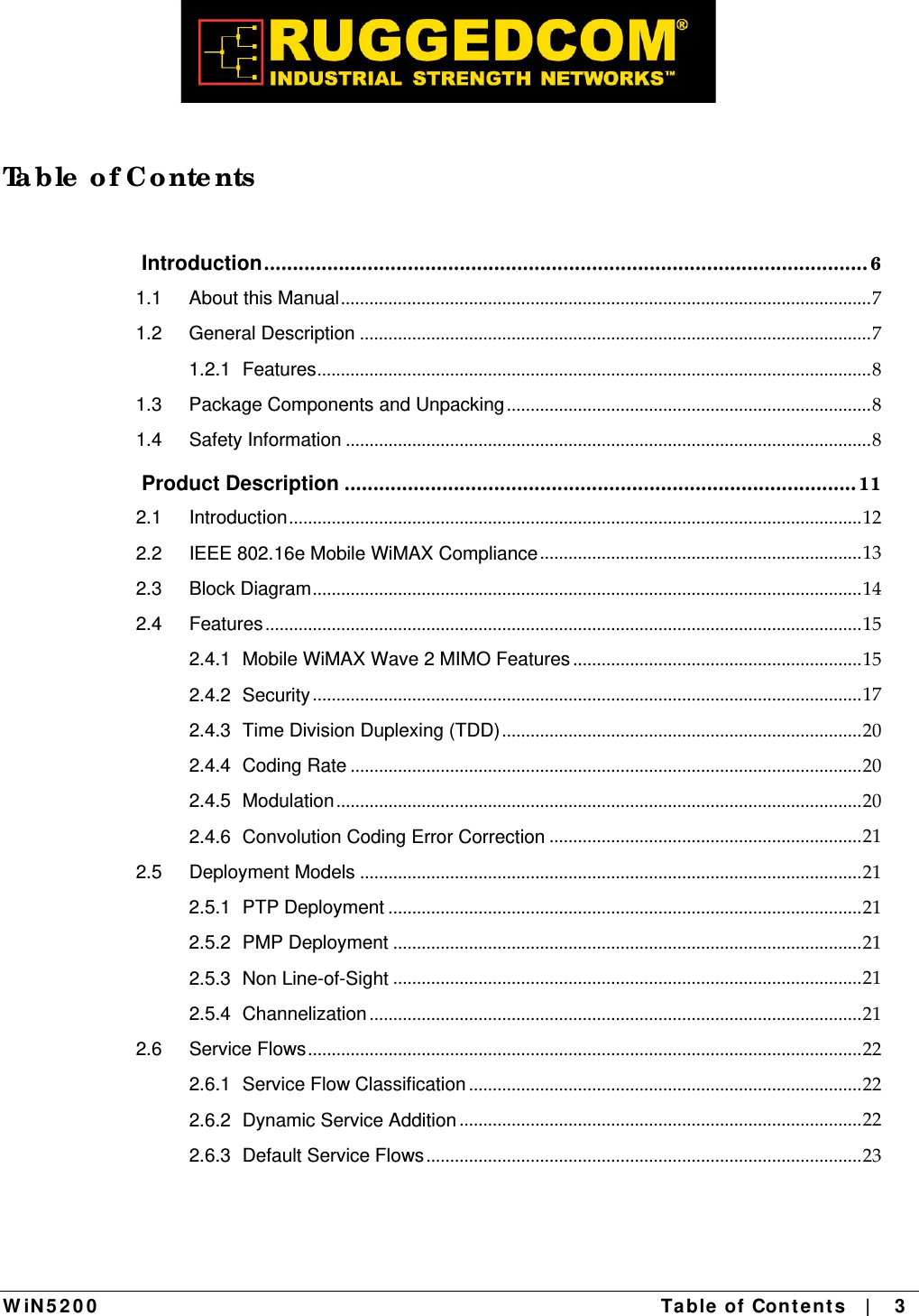
![W iN 5 2 0 0 Product De scr ipt ion | 1 7 characteristicsofasubscriber’sparticularfrequencychannel.OnesuchSTCtechnique,knownastheAlamoutiCode,waspublishedin1998[4]andhasbeenincorporatedintotheWiMAX16estandard.2.4.2 Se c urity Securitywasakeyfailingofolderbroadbandwirelesssystemsofthepast.Thewhyofitiseasytocomprehend‐‐‐anynetworkthattransmitsitsdataacrosswirelesssignalsratherthanwiresisinherentlymoreopentointerference,intrusionorassault.Thisdoesnotmeansolidbroadbandwirelesssecurityisimpossible,justmuchmoredifficult.Asbroadbandwirelessnetworkshavematuredsecurityfeatureshaveimproved.WiththeadventofWiMAX,thesecuritytoolsetsavailabletobroadbandwirelessserviceprovidershavereachedalltimehighsoffunctionality.TodaysWiMAXnetworkscanbesecuredmoreeffectivelythaneverbefore.WiMAXandIEEE802.16SecuritySublayerprovidesforprivacy,authenticationandconfidentialityacrossthebroadbandwirelessnetwork.DefinedinitiallybyIEEE802.16‐2004andthencorrectedandamendedbyCorrigendum1andIEEE802.16e‐2005respectively,theSecuritySublayernowsupportsFixedandMobileoperation.Therearetwomajordifferencesbetweenthestandards.ThefirstdifferenceisthatthesecuritymechanismoftheIEEE802.16‐2004isbasedontheDOCSISstandard.Inthe802.16e‐2005manychangeshavebeenmadeinthesecuritymechanisms.TheseconddifferenceisintheflexibilityofSSsconnectioncharacteristicswiththeBST.TheIEEE802.16‐2004onlysupportsfixedaccess.Infixedaccess,anSScannotmitigatetotheairinterfaceofanewBaseStation(BST)withoutperformingthenetworkentryagainafteraconnectiontermination.TheIEEE802.16e‐2005supportsmobileaccess.MobileaccessenablesanSStomovebetweenvariousBSTcellswhilekeepingtheconnectionestablished.TherearefiveprimaryaspectsofWiMAXsecuritythatshouldbeconsideredwhendesigningasecurityplanforaWiMAXnetwork.Theserangefrommitigationtechniquesatthephysicallayertoimprovedwirelessauthenticationandencryptiontointrusionprotectionanddatatransportsecurity.Ateachlevel,choicesinimplementationandsecuritylevelscanbemade;althoughinthecaseofthephysicallayeroptionsarelimited.2.4.2.1 Physic a l La ye r Se c urity TherearetwobasictypesofattacksthatcanaffectthephysicallayerofWiMAX.Oneisjammingandtheotherispacketscrambling.Thefirstisrelativelystraightforward,andissometimestheresultofinterferenceratherthananattack.Jammingconsistsofastronger](https://usermanual.wiki/Siemens-Canada/5237001.User-manual/User-Guide-1488769-Page-17.png)


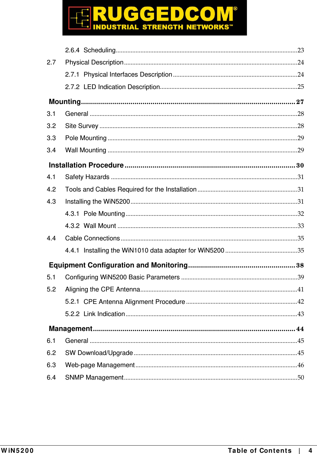
![List of Acronyms W iN 5 2 0 0 Appendix A – Pr oduct Spe cificat ion | 5 6 Radio and Modem: Frequency WiN5125-XX, WiN5225: 2496 MHz to 2690 MHz WiN5237: 3650 MHz to 3700 MHz Radio Access Method IEEE802.16-2005 (16e OFDMA) Operation Mode TDD Compatibility WiN52XX-2: Wave 2 Profile (MIMO) Channel Bandwidth WiN5125-XX, WiN5225: 5 MHz, 7MHz, 10 MHz WiN5137-XX, WiN5237: 5 MHz ,7MHz, 10 MHz Frequency Resolution 0.25 MHz Antenna Support Integral/External Number of Antennas 2 Antenna Diversity Support STC/MIMO Output Power [P1dB] 2W Output Power (average) 24 dBm +/-1dB maximum TPC 45dB FFT/Modulation 1024/512 FFT points; QPSK, 16QAM, 64QAM FEC Convolution Code and Turbo Code Dynamic range RX: -100dBm :-20 dBm TX: -20dBm : +24 dBm Data Communication (Through indoor unit): Ethernet Standard Compliance IEEE 802.3 CSMA/CD Ethernet Port 10/100 Mbps, Half/Full Duplex with Auto Negotiation VLAN Support IEEE 802.1Q Traffic Classification IEEE 802.1p DiffServ (DSCP) Max User Throughput DL: 12Mbps, UL: 6Mbps Ordering Information: Part Number WiN52XX-2-02-W XX – Frequency range See frequency table for details Indoor Unit (ETH) Compatibility: WiN1010 Data Adapter Configuration and Management: Local Management Telnet SNMPv2 Web Browser Remote Management SNMPv2 over wireless via the base station SNMP Agent SNMP ver 2 client: MIB II (RFC 1213), Private Win-Max MIBs Authentication EAP-TTLS: Device: X509 digital certificate User: MS-CHAP Software Upgrade FTP Remote Configuration FTP Mechanical, Electrical and Environmental: Dimensions (w/o the antenna) [H, W, D] 224 x 92 x 61 mm Weight 1.5 kg Power Source 48VDC from the indoor unit over the indoor-outdoor cable Power Consumption 17W maximum Operating Temperature -40C to +55C Operating Humidity 5%-95% non condensing, Weather protected Standards Compliance: EMC FCC part 15, subpart B, class B ETSI EN 301489-1/4 Safety TUV-UL 60950-1 EN 60950-1 Radio FCC Part27 ETSI EN 302 326-1/2/3 Environmental Enclosure ETS 300 019 Type 3R (IP66) ](https://usermanual.wiki/Siemens-Canada/5237001.User-manual/User-Guide-1488769-Page-56.png)