Siemens Canada 5237001 Subscriber unit transceiver User Manual
Siemens Canada Limited Subscriber unit transceiver
Contents
- 1. User manual
- 2. Users Manual
User manual

User’s Manual & Installation Guide for:
WiN52XX/WiN51XX Series Outdoor CPE

ALL RIGHTS RESERVED
Dissemination or reproduction of this document, or evaluation and communication of its contents, is not authorized except where
expressly permitted. Violations are liable for damages. All rights reserved, particularly for the purposes of patent application or trademark
registration.
This document contains proprietary information, which is protected by copyright. All rights are reserved. No part of this document may be
photocopied, reproduced or translated to another language without prior written consent of RuggedCom Inc.
Disclaimer Of Liability
We have checked the contents of this manual against the hardware and software described. However, deviations from the description
cannot be completely ruled out.
RuggedCom shall not be liable for any errors or omissions contained herein or for consequential damages in connection with the
furnishing, performance, or use of this material.
The information given in this document is reviewed regularly and any necessary corrections will be included in subsequent editions. We
appreciate any suggested improvements. We reserve the right to make technical improvements without notice.
Registered Trademarks
RuggedMAX-BST™, RuggedServer™, RuggedWireless™, RuggedCom Discovery Protocol™ (RCDP™), RuggedExplorer™, Enhanced
Rapid Scanning Tree Protocol™ (eRSTP™), are trademarks of RuggedCom Inc. Rugged Operating System® (ROS®) and
RuggedSwitch® are registered trademarks of RuggedCom Inc. Other designations in this manual might be trademarks whose use by
third parties for their own purposes would infringe the rights of the owner.
Warranty
Five (5) years from date of purchase, return to factory. For warranty details, visit www.ruggedcom.com or contact your customer service
representative.
Contacting RuggedCom
Corporate Headquarters US Headquarters Europe Headquarters
RuggedCom Inc
30 Whitmore Road
Woodbridge, Ontario
Canada, L4L 7Z4
Tel: (905) 856-5288
Fax: (905) 856-1995
Toll-free: 1 (888) 264-0006
RuggedCom
1930 Harrison St., Suite 209
Hollywood, Florida
USA, 33020
Tel: (954) 922-7938x103
Fax: (954) 922-7984
Toll-free: 1 (888) 264-0006
RuggedCom
Unit 41, Aztec Centre,
Aztec West, Almondsbury, Bristol
United Kingdom BS32 4TD
Tel: +44 1454 203 404
Fax: +44 1454 203 404
Toll-free: 1 (888) 264-0006
Email: RuggedSales@RuggedCom.com

W iN 5 2 0 0 Table of Cont en t s | 3
Ta b le o f Co nte nts
Introduction......................................................................................................... 6
1.1About this Manual................................................................................................................7
1.2General Description ............................................................................................................7
1.2.1Features.....................................................................................................................8
1.3Package Components and Unpacking.............................................................................8
1.4Safety Information ...............................................................................................................8
Product Description ......................................................................................... 11
2.1Introduction.........................................................................................................................12
2.2IEEE 802.16e Mobile WiMAX Compliance....................................................................13
2.3Block Diagram....................................................................................................................14
2.4Features ..............................................................................................................................15
2.4.1Mobile WiMAX Wave 2 MIMO Features .............................................................15
2.4.2Security....................................................................................................................17
2.4.3Time Division Duplexing (TDD)............................................................................20
2.4.4Coding Rate ............................................................................................................20
2.4.5Modulation...............................................................................................................20
2.4.6Convolution Coding Error Correction ..................................................................21
2.5Deployment Models ..........................................................................................................21
2.5.1PTP Deployment ....................................................................................................21
2.5.2PMP Deployment ...................................................................................................21
2.5.3Non Line-of-Sight ...................................................................................................21
2.5.4Channelization ........................................................................................................21
2.6Service Flows.....................................................................................................................22
2.6.1Service Flow Classification ...................................................................................22
2.6.2Dynamic Service Addition .....................................................................................22
2.6.3Default Service Flows............................................................................................23

W iN 5 2 0 0 Table of Cont en ts | 4
2.6.4Scheduling...............................................................................................................23
2.7Physical Description..........................................................................................................24
2.7.1Physical Interfaces Description ............................................................................24
2.7.2LED Indication Description....................................................................................25
Mounting............................................................................................................ 27
3.1General ...............................................................................................................................28
3.2Site Survey .........................................................................................................................28
3.3Pole Mounting ....................................................................................................................29
3.4Wall Mounting ....................................................................................................................29
Installation Procedure ...................................................................................... 30
4.1Safety Hazards ..................................................................................................................31
4.2Tools and Cables Required for the Installation .............................................................31
4.3Installing the WiN5200 ......................................................................................................31
4.3.1Pole Mounting.........................................................................................................32
4.3.2Wall Mount ..............................................................................................................33
4.4Cable Connections............................................................................................................35
4.4.1Installing the WiN1010 data adapter for WiN5200 ............................................35
Equipment Configuration and Monitoring...................................................... 38
5.1Configuring WiN5200 Basic Parameters .......................................................................39
5.2Aligning the CPE Antenna................................................................................................41
5.2.1CPE Antenna Alignment Procedure ....................................................................42
5.2.2Link Indication.........................................................................................................43
Management...................................................................................................... 44
6.1General ...............................................................................................................................45
6.2SW Download/Upgrade ....................................................................................................45
6.3Web-page Management...................................................................................................46
6.4SNMP Management..........................................................................................................50

W iN 5 2 0 0 Table of Cont en ts | 5
Appendix A – Product Specification............................................................... 51
Appendix B – IDU to ODU Cable Specifications ............................................ 52
List of Acronyms .............................................................................................. 54

W iN 5 2 0 0 I ntr oduct ion | 6
1
ntro duc tio n

W iN 5 2 0 0 I ntr oduct ion | 7
1.1 Ab o ut this Ma nua l
ThismanualdescribestheinstallationproceduresofWiN51XX/WiN52XXOutdoorCPEwith
Ethernetinterfaceandiswrittenfortheinstallersandoperators.
WiN51XX/WiN52XX2productswillbereferredinthismanualasWiN5200fromnowon.
TheRuggedComWiN5200isamemberoftheWin‐Max™Efamily,alineofmobileWiMAX
broadbandwirelessaccesssystemsbasedonthe802.16emobileWiMAXstandard.TheWin‐
Max™EfamilyisdetailedintheSystemDescriptionmanualofRuggedCom.
ThismanualassumesthatusershavesomeexperiencewithWiMAXtechnologiesand
procedures.
Whilesomesafetyprecautionsarereviewedhere,thismanualassumesthatinstallershave
beentrainedinsafeinstallationpractices.Users,whoarenewtoWiMAXtechnologiesand
serviceprocedures,shouldnotrelyonthismanualforcomprehensiveguidance.
1.2 G e ne ra l De sc riptio n
TheRuggedComWiN5200ODUisamemberoftheWin‐Max™Efamily,alineofWiMAX
BroadbandWirelessAccesssystemsbasedonthe802.16emobileWiMAXstandard,specially
designedforquadruple‐playapplications.
WiN5200isahigh‐performanceoutdoorunitthatprovidescomplete802.16emobileWiMAX
broadbandwirelessaccessfunctionalitytoarangeofindoormulti‐servicegateways.
TheWiN5200enablesthefullscopeoftriple‐play(includingtelephony,data,Video‐on‐Demand)
overtheWiMAXnetwork.Inthehome,tripleplayservicesaredistributedtoasinglegateway
forasimplehome‐networkingsolution.
TheWiN5200isbasedontheIEEE802.16estandardstoeffectivelymeettheuniquerequirements
ofthewirelessMetropolitanAreaNetwork(MAN)environmentandtodeliverbroadband
accessservicestoawiderangeofcustomers.Specificallydesignedforpoint‐to‐multipoint
broadbandwirelessaccessapplications,theWiN5200providesefficientuseofthewireless
spectrum,supportingarangeofuserenvironments.Theaccessandbandwidthallocation
mechanismsaccommodatehundredsofsubscriberunitspersector,supportingdifferentiated
servicestoamultipleofend‐users.

W iN 5 2 0 0 I ntr oduct ion | 8
1.2.1 Fe a ture s
IntelligentWiMAXsubscriberunitforwirelesstriple‐playservicedelivery
OutdoorunitwithETHinterfacetoindoorunit
Automatic,self‐configured,plug‐n‐play
Supporting1.X,2.Xand3.XGHzbands
1.3 Pa c ka g e Co m po ne nts a nd Unpa c king
Checkthatthepackagecontains:
1.WiN52xxODUwithintegratedflatantenna
2.Pole/wallmountinghardware
Incaseofdamage,contacttheshippingcompany.
1.4 Sa fe ty Info rma tio n
RF Ex posur e
TheWiN5200,anoutdoorCPE,iscompliantwiththerequirementssetforthinCFR47section
1.1307,addressingRFExposurefromradiofrequencydevicesasdefinedinOETBulletin65.
TheoutdoorCPEmobileunitshouldbepositionedmorethan0.6feet(20cm)fromhumans.
TheoutdoorCPEfixedunitshouldbepositionedatleast7feet(2m)fromhumans.
Ligh t ning Prot e ct ion
WhenWiN5200isinstalledinanoutdoorlocation,allindoorcomponents(Ethernet,power
supply)shouldbeconnectedthroughalightningprotector.
Thepurposeofthelightningprotectionistoprotectpeopleandequipmentlocatedindoors
fromlightningthatmightstriketheWiN5200oritsoutdoorcables.Therefore,thelightning
protectordeviceshouldbeinstalledindoors,ascloseaspossibletothepointwherethecables
enterthebuilding.Thelightningprotectorcanalsobeinstalledoutdoors,aslongasthecables
thatleadfromitindoorsarewellprotectedfromlightningbetweentheboxandthebuilding
entrance.
Pow er Cord Prote ct ion
TheWiN5200shouldalwaysbeconnectedtotheWiN1010dataadapterforbothpower
supplyanddatatransferpurposes.

W iN 5 2 0 0 I ntr oduct ion | 9
Anyothertypeofconnection/applicationoftheWiN5200and/orWiN1010isnotallowed.
Routeallpowersupplycordssothatpeoplecannotwalkonthem,orplaceobjectsonor
againstthem.Thiscanpinchordamagethecords.
Se rvicing
Donotopenthecoverofthisproductandperformcorrectiveactionsunlessinstructedtodo
sointheoperatinginstructions.
Out door Grounding Syste m
Verifythattheantennaorcablesystemisgrounded(earthed).
TheantennaisanintegralpartoftheCPE(ModelsWiN51XX)
TheCPE(antenna)installationmustbeasperArticle810oftheNEC.Ofparticularnoteisthe
requirementthatthegroundingconductornotbelessthan10AWG(Cu).Theschemeshould
beeitherinaccordancewithUL96and96A.LightningProtectionComponentsand
InstallationRequirementsforLightningProtectionSystems,ortestedinaccordancewithUL
50andUL497.
CAUTI ON
Toreducetheriskoffire,useonlyNo.26AWGorlargertelecommunicationlinecord
betweentheindoorandoutdoorunits.

W iN 5 2 0 0 I ntr oduct ion | 1 0
NOTE:Thisequipmenthasbeentestedandfoundtocomplywiththelimits
foraClassBdigitaldevice,pursuanttopart15oftheFCCRules.Theselimits
aredesignedtoprovidereasonableprotectionagainstharmfulinterferenceina
residentialinstallation.Thisequipmentgenerates,usesandcanradiateradio
frequencyenergyand,ifnotinstalledandusedinaccordancewiththe
instructions,maycauseharmfulinterferencetoradiocommunications.
However,thereisnoguaranteethatinterferencewillnotoccurinaparticular
installation.Ifthisequipmentdoescauseharmfulinterferencetoradioor
televisionreception,whichcanbedeterminedbyturningtheequipmentoffand
on,theuserisencouragedtotrytocorrecttheinterferencebyoneormoreofthe
followingmeasures:
‐Reorientorrelocatethereceivingantenna.
‐Increasetheseparationbetweentheequipmentandreceiver.
‐Connecttheequipmentintoanoutletonacircuitdifferentfromthattowhich
thereceiverisconnected.
‐Consultthedealeroranexperiencedradio/TVtechnicianforhelp.
ThisdevicecomplieswithPart15oftheFCCRules.
Operationissubjecttothefollowingtwoconditions:
(1)Thisdevicemaynotcauseinterference,and(2)thisdevicemustacceptany
interference,includinginterferencethatmaycauseundesiredoperationofthe
device
Changesormodificationstothisequipmentnotexpresslyapprovedbytheparty
responsibleforcompliance(RuggedComInc.)couldvoidtheuser’sauthorityto
operatetheequipment.

W iN 5 2 0 0 Product De scr ipt ion | 1 1
2
ro duc t De sc riptio n

W iN 5 2 0 0 Product De scr ipt ion | 1 2
2.1 Introduc tio n
TheWiN5200ODUCPEisanIEEE802.16‐2005compliantwirelessdevicefordeploymentof
point‐to‐multipoint(PMP)andpoint‐to‐point(PTP)networkarchitectures.
TheWiN5200ODUCPEisanoutdoordevice.TheWiN5200ODUCPEisWiMAXForum
802.16eWave2(MIMO)Certifiedsubscribers.Eachsubscriberregistersandestablishesabi‐
directionaldatalinkwiththebasestationsectorcontroller.
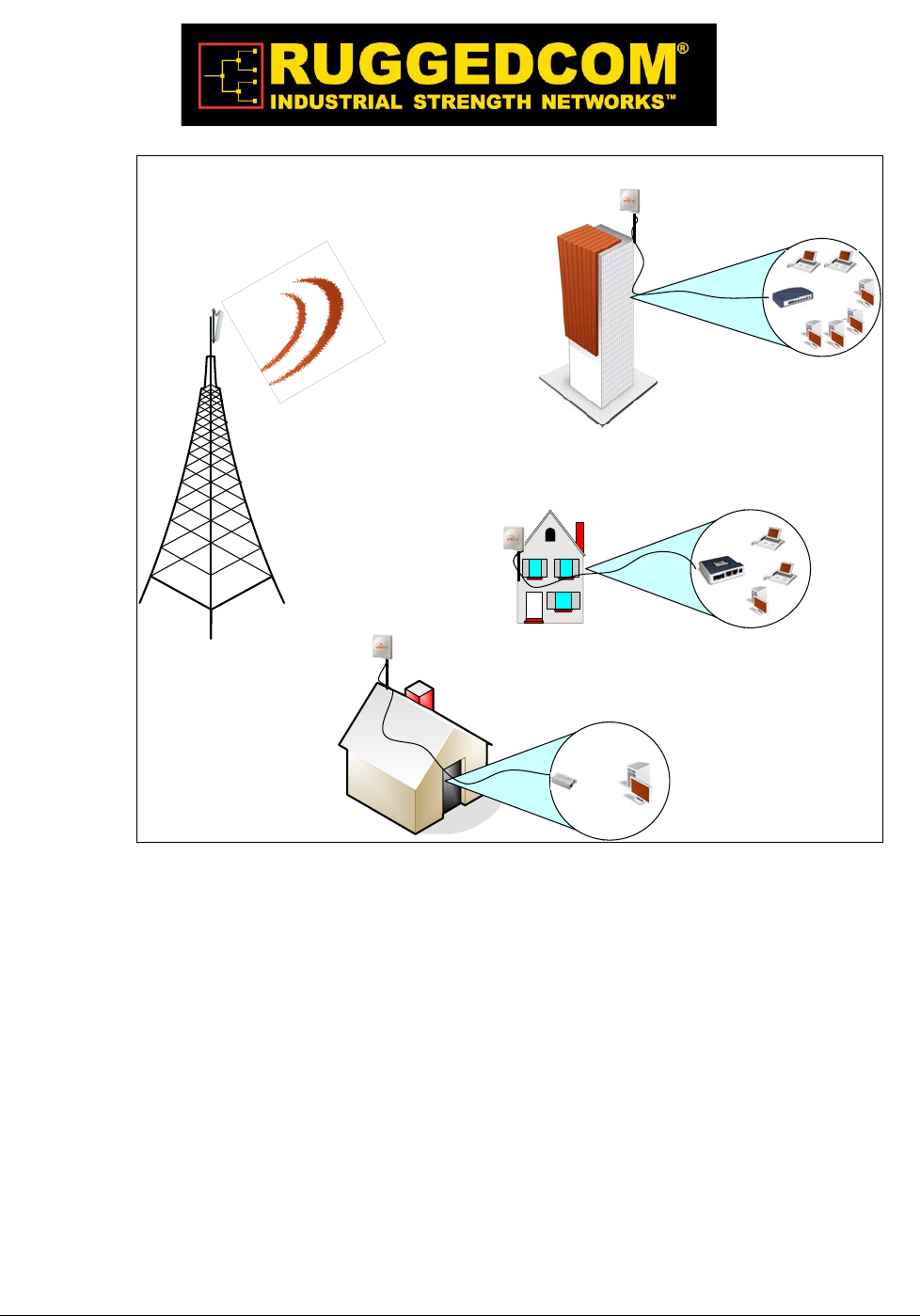
TheCPEterminalsaregroupedintotwoclasses,OutdoorCPEsandResidentialGateways
(RG)whichareindoorunits.Therelationshipbetweenalltheunitsisillustratedbelow.
W iN 5 2 0 0 Product De scr ipt ion | 1 3
House
RG
WiN1030-1
RG
WiN1020-1
RG
WiN1010-1
CPE
WiN52xx
BST
WiN70xx
CPE
WiN52xx
CPE
WiN52xx
Figure 2-1: Functional Overview of the CPEs
Thebasestationisconnectedtothehead‐endoverIPBackhaulorviawirelesschannels.The
outdoorCPEsareconnectedtothebasestationoverwirelesschannels.TheoutdoorCPEis
connectedtotheindoorresidentialgatewayoverEthernetorcoaxialnetworks.
2.2 IEEE 802.16e Mo b ile WiMAX C o mplia nc e
TheIEEE802.16‐2005specificationsdescribeaPMPbroadbandwirelessaccessstandardfor
systems.ThisstandardincludesdescriptionsforboththeMediaAccessControl(MAC)and
thephysical(PHY)layers.
TheWiN5200ODUCPEiscomplianttoIEEE802.16‐2005WiMAXforumWave2profile.

W iN 5 2 0 0 Product De scr ipt ion | 1 4
N ot e
The 802.16e standards are subject to amendment, and Win-MaxTM product family design compliance
applies to a specific revision of the standard. The Win-MaxTM product family does not support mesh
communication (direct subscriber-to-subscriber).
2.3 Blo c k Dia g ra m
TheCPEconsistsofthefollowingmodules:
1.Base‐Bandboard–includingtheWiMAX16eMIMOBase‐BandSoC(runningthe16e
MAC+PHY)plustheUserInterfaceplustheanalogfrontendthatinterfacetheRF
module.
2.PowerSupplyboard–DC/DCpowersupply.Convertsthe48VDCtothevariousvoltages
thatarefeedingtheDigitalandtheRFmodules
3.RFboard‐SingletransmitdualreceivemodulethatmodulatetheanalogWiMAXsignal
inputfromtheBase‐BandmodemtothehighfrequencyRFoutput.SeveralRFmodules
exist‐eachsupportingdifferentfrequencyband.
4.Chassis
5.Antenna–IntegrateddualpolarizationantennatosupporttheMIMOschemes
W iN 5 2 0 0 Product De scr ipt ion | 1 5
Base-Band
RF
Power Supply
Indoor-Outdoor Cable
Antenna
Figure 2-2: WiN5200 Block Diagram
2.4 Fe a ture s
2.4.1 Mo bile WiMAX Wa ve 2 MIMO Fe a ture s
Multiple‐Input,Multiple‐Output(MIMO)describessystemsthatusemorethanoneradioand
antennasystemateachendofthewirelesslink.Inthepastitwastoocostlytoincorporate
multipleantennasandradiosinasubscriberterminal.Recentadvancesinradio
miniaturizationandintegrationtechnologynowmakesitfeasibleandcosteffective.
Combiningtwoormorereceivedsignalshastheimmediatebenefitofimprovingreceived
signalstrength,butMIMOalsoenablestransmissionofparalleldatastreamsorgreater
throughput.Forexample,ina2x2MIMO(twotransmitandtworeceiveelements),dual
polarizationpoint‐to‐pointsystem,thecarrier’sallocatedfrequencycanbeusedtwice,
effectivelydoublingthethroughputdatarate.
Inpoint‐to‐multipointsystemsemployingMIMO,eachbasestationantennatransmitsa
differentdatastreamandeachsubscriberterminalreceivesvariouscomponentsofthe
transmittedsignalswitheachofitssubscriberantennasasillustratedinthefigurebelow.By
W iN 5 2 0 0 Product De scr ipt ion | 1 6
usingappropriatealgorithms,thesubscriberterminalisabletoseparateanddecodethe
parallelsimultaneouslyreceiveddatastreams.
Figure 2-3: MiMo Antenna System
2.4.1.1 Spa c e - Tim e Co ding
Space‐timecoding(STC)isatechniqueforimplementingtransmissiondiversity.Mobile
WiMAXusestransmitdiversityinthedownlinkdirectiontoprovidespatialdiversitythat
enhancesthesignalqualitytoaspecificsubscriberlocatedanywherewithintherangeofthe
antennabeam.Althoughprovidinglesssignalgainthanbeam‐forming,transmitdiversityis
morerobustformobileuserssinceitdoesnotrequirepriorknowledgeofthepath
MiMoMiMo

W iN 5 2 0 0 Product De scr ipt ion | 1 7
characteristicsofasubscriber’sparticularfrequencychannel.OnesuchSTCtechnique,
knownastheAlamoutiCode,waspublishedin1998[4]andhasbeenincorporatedintothe
WiMAX16estandard.
2.4.2 Se c urity
Securitywasakeyfailingofolderbroadbandwirelesssystemsofthepast.Thewhyofitis
easytocomprehend‐‐‐anynetworkthattransmitsitsdataacrosswirelesssignalsratherthan
wiresisinherentlymoreopentointerference,intrusionorassault.Thisdoesnotmeansolid
broadbandwirelesssecurityisimpossible,justmuchmoredifficult.
Asbroadbandwirelessnetworkshavematuredsecurityfeatureshaveimproved.Withthe
adventofWiMAX,thesecuritytoolsetsavailabletobroadbandwirelessserviceproviders
havereachedalltimehighsoffunctionality.TodaysWiMAXnetworkscanbesecuredmore
effectivelythaneverbefore.
WiMAXandIEEE802.16SecuritySublayerprovidesforprivacy,authenticationand
confidentialityacrossthebroadbandwirelessnetwork.DefinedinitiallybyIEEE802.16‐2004
andthencorrectedandamendedbyCorrigendum1andIEEE802.16e‐2005respectively,the
SecuritySublayernowsupportsFixedandMobileoperation.
Therearetwomajordifferencesbetweenthestandards.Thefirstdifferenceisthatthesecurity
mechanismoftheIEEE802.16‐2004isbasedontheDOCSISstandard.Inthe802.16e‐2005
manychangeshavebeenmadeinthesecuritymechanisms.Theseconddifferenceisinthe
flexibilityofSSsconnectioncharacteristicswiththeBST.TheIEEE802.16‐2004onlysupports
fixedaccess.Infixedaccess,anSScannotmitigatetotheairinterfaceofanewBaseStation
(BST)withoutperformingthenetworkentryagainafteraconnectiontermination.TheIEEE
802.16e‐2005supportsmobileaccess.MobileaccessenablesanSStomovebetweenvarious
BSTcellswhilekeepingtheconnectionestablished.
TherearefiveprimaryaspectsofWiMAXsecuritythatshouldbeconsideredwhendesigning
asecurityplanforaWiMAXnetwork.Theserangefrommitigationtechniquesatthephysical
layertoimprovedwirelessauthenticationandencryptiontointrusionprotectionanddata
transportsecurity.Ateachlevel,choicesinimplementationandsecuritylevelscanbemade;
althoughinthecaseofthephysicallayeroptionsarelimited.
2.4.2.1 Physic a l La ye r Se c urity
TherearetwobasictypesofattacksthatcanaffectthephysicallayerofWiMAX.Oneis
jammingandtheotherispacketscrambling.Thefirstisrelativelystraightforward,andis
sometimestheresultofinterferenceratherthananattack.Jammingconsistsofastronger

W iN 5 2 0 0 Product De scr ipt ion | 1 8
signalthantheWiMAXnetworkoverwhelmingnetworkdatafeedseitherinintermittent
burstsorwithsustainedcarrierwaves.
SincemostWiMAXnetworkservicesaredeliveredoverlicensedbands(currently3.5GHz
internationallyand2.5GHzbothinternationallyandintheUS),thisoffersspectrum
relativelyquietfromaccidentalinterference.Accidentalinterferenceinlicensedspectrum
cannotalwaysbecompletelydiscountedasthereisapossibilityofsecondandthirdharmonic
interferencewaves,forexample,frommuchlowerfrequencysignalsifthoseareinclose
proximitytotheWiMAXantennasystemsorthatcrossthemwithasignalcloseenoughin
physicalproximitytolocallyoverloadtheWiMAXsignal.Inpractice,thisisrare.
Packetscramblingisanattackthatoccurswhencontrolpacketsintherespectivedownlink
anduplinksubframesaresniffedthenscrambledandreturnedtothenetwork.Thisattackis
muchhardertomountthanajammingattack.SincemostWiMAXnetworkstodayusetime
divisionduplexing(TDD),toincludetheWin‐Max™system,anattackercanparsethis
timingsequenceandcapturecontroldata,thepreambleandmap,scramblethemandsend
thembackwithcorrecttimingtointerruptlegitimatesignal,resultinginslowdownsand
effectivelyloweredbandwidth.Interceptedandscrambledpacketsarepossiblewith
frequencydivisionduplexing(FDD)aswellwhichtransmitsboththeuplinkanddownlink
simultaneously,butitisevenhardertoexploitthisattackthanwithTDDsystems.
Whileitmayseemthephysicallayerisinherentlymostvulnerableasthesecurityelementsof
WiMAXarelocatedathigherlayers,thefactishackerscanoftenfindlowerhangingfruitin
termsofusefulexploitshigherinthestack,becauseasWiMAXsupportsmultipleselections
onwhatserviceproviderscanchoosetoimplementintermsofauthentication,sometimesthe
doorcanbeleftopenforthembythechoicesmade.
2.4.2.2 Authe ntic a tio n
Traditionallythefirstlevelofsecurityauthenticationforolderbroadbandwireless
technologieshasbeenMACauthenticationandWiMAXsupportsthis,althoughproviders
dontsettleforthismethod.ThistechniqueallowedserviceproviderstologpermittedMAC
deviceaddressesandallowonlythoseaddressestoaccessthenetwork.Hackerslongago
figuredouthowtospoofthese.Ifabasestationisnotsetupwithadequateauthentication
measures,anattackercancapturecontrolpacketsandposeasalegitimatesubscribereven
witholderMACdeviceauthenticationenabled.
Asecond,newerandmuchbetterchoice,embracedbytheWin‐Max™system,isthebuiltin
supportforX.509devicecertificatesembeddedwiththeuseofextensibleauthentication
protocol‐‐‐transportlayersecurity(EAP‐TTLS)method,addedwiththe802.16estandardand
WiMAXForum.

W iN 5 2 0 0 Product De scr ipt ion | 1 9
EntertheEAP‐TLTSauthenticationmethod.Thistechniqueallowsboththesubscriberand
thebasestationtoauthenticateeachotherusinganX.509methodforboth,inadditiontoa
subscriberauthenticationwhichisbasedonwell‐knownsubscriberauthenticationtechniques
suchPAPandMS‐CHAP.MACcontrolheadersareneverencryptedinWiMAX,however
withEAPcarrierscanchoosetoauthenticatethem(buttheydontnecessarilyhaveto).This
capabilityaddsanadditionallayerofauthenticationconfirmation.Itsanoperatorspecific
guidelinedecisionandistunableintheWin‐Max™system.
2.4.2.3 Enc ryptio n
ClearlythefirstlayerofdefenseforWiMAXoperatorsistoauthenticatealegitimateuseron
itsnetwork.However,WiMAX,withits802.16eratification,offerstoplinetoolsfor
encryptionofdata.Olderwirelessiterationsusedthedataencryptionstandard(DES)which
reliedona56‐bitkeyforencryption.Thisislargelyconsideredobsolete.WiMAX802.16e
certainlysupportsDES(3DES)butitalsoaddssupportfortheAdvancedEncryption
Standard(AES)whichsupports,128‐bit,192‐bitor256‐bitencryptionkeys.AlsoAESmeets
theFederalInformationProcessingStandard(FIPS)140‐2specification,requiredby
numerousgovernmentalbranches.Thistechnology,whichrequiresdedicatedprocessorson
boardbasestations,isrobustandhighlyeffective.
Trafficencryptionmaybeemployedper802.16ServiceFlowandissubjecttooperatorpolicy.
Therelevanceofencryptiontothenetworkoperatordeploymentisquestionable.Inthepast,
forexample,manycellularcarriersfocusedonauthenticationandmostlyignoredencryption.
Whetherthatwillchangeasmobileserviceprovidersrampupmorebroadbandapplications
isanopenquestion.
Thedownsidetotheseheavycomputingtasks(i.e.authenticationandencryption)isthatall
ofthisrequiresprocessorcycles,whichmayaffecttheperformanceofthesystem.
Nevertheless,theWin‐Max™systemandespecially,theSSandBST,whicharetheentities
thattakeactiveroleinheavysecurity‐relatedcomputations,werebuiltbottomtotopwitha
designgoalofoffloadingheavilycomputingtasksfromthehostprocessortoaspecificcircuit.
Consequently,noperformancedegradationisneglected.
2.4.2.4 Third Pa rty Intrusio n Pro te c tio n
WeexaminedWiMAXauthenticationschemes,whichareamajorcomponentofasecure
network.Andwealsospokeofdataencryption.Clearly,WiMAXpossessessolidtools
alreadybuiltin.Butthereareconsiderationsbeyondjustgoodsecuritythatcandrivea
migrationtothirdpartyintrusiondetectionandprotectiontools‐‐‐namelybusinesscase
elements.Intrusionprotectionishowever,notdataprotection.Thesearetwodifferentclasses
ofsolution.Certainly,agoodthirdpartyintrusionprotectioncanmonitorandsecurea
networksauthentication.However,manysolutionsalsoofferwormprotection,Trojanhorse

W iN 5 2 0 0 Product De scr ipt ion | 2 0
protection,defensesagainstviruses,backdoorexploitsanddenialofserviceattackstonamea
few.Someoftheseelementsarealmostabusinessnecessityforawirelessserviceprovider
andmayjustifythecostofanadditionalsecuritysuiteinitially.Forothercompanies,a
migrationstrategytoenhancedtoolsmakesthemostcosteffectivesense.
Agoodplacetostartisexaminingmarketandservicescenarios.Ifyourcustomerbaseis
highlysensitivetodataintegrity(financialsectororhospitalcustomers)thirdpartyintrusion
preventionsystemscanhelpsegmentcustomersfromeachotherbetteraswellassecurethem
fromoutsideattack.
Orinanotherexample,amobilenetworkthatoffersjustInternetaccessandvoicemaywish
toabrogateresponsibilityfordataencryptionandusesessioninitiationprotocol(SIP)
signalingforitsVoIPandWiMAXnativeauthenticationtools.
Referringtoencryption,clearlyanAESsupporteddataencryptionsystemgivesWiMAX
excellentsecurityinthisregard.However,additionalsolutionsthatmeetcustomerneeds
suchasvirtualprivatenetworksmayenhancethebusinessmodelandprovideadditional
sourceofrevenue.
2.4.3 Tim e Divisio n Duple xing (TDD)
TheWiN5200CPEusestimedivisionduplexing(TDD)totransmitandreceiveonthesame
RFchannel.Thisisanon‐contentionbasedmethodforprovidinganefficientandpredictable
two‐wayPTPorPMPcelldeployment.Alluplinkanddownlinktransmissionschedulingis
managedbythebasestation.Thebasestationsendsdatatraffictosubscribers,pollsforgrant
requests,andsendsgrantacknowledgementsbasedonthetotalofalltraffictoallsubscribers.
2.4.4 C o ding Ra te
Eachburstofdatatransmittedoverthewirelessinterfaceispaddedwithredundant
information,makingitmoreresistanttopotentialover‐the‐airerrors.Thecodingrateisthe
ratioofuserdatatothetotaldatatransmittedincludingtheredundanterrorcorrectiondata.
Thebasestationsupportscodingratesof1/2,2/3,and3/4.
2.4.5 Mo dula tio n
ThemodulationtechniquespecifieshowthedataiscodedwithintheOFDMAcarriers.The
basestationsupportsQPSK,16QuadaratureAmplitudeModulation(QAM),and64QAM
modulations.

W iN 5 2 0 0 Product De scr ipt ion | 2 1
2.4.6 Co nvo lutio n C o ding Erro r C o rre c tio n
ConvolutionCoding(CC)errorcorrectionisenabledforalltrafficrates.Thislow‐level
processcancorrectburstsoferrorsinreceivedmessagesandreducethenumberof
retransmissions.
2.5 De plo ym e nt Mo de ls
TheCPEsupportspointtopoint(PTP)andpointtomultipoint(PMP)deploymentscenarios.
2.5.1 PTP De plo yme nt
WhendeployedinaPTPconfigurationthebasestationestablishesadedicatedbidirectional
linktoasinglesubscriber.ThePTPdeploymentstypicallyuseadirectionalnarrowbeam
antennaforbothendsofthelink.
2.5.2 PMP De plo ym e nt
WhendeployedinaPMPconfigurationthebasestationestablishesbi‐directionallinksto
morethanonesubscriber.PMPdeploymentstypicallyuseawidebeam(sector)antennaat
thebasestationandanarrowbeamantennaatthesubscriber.Serviceflowsareusedtopolice
servicelevelagreementsforeachsubscriber.
2.5.3 No n Line - o f- Sig ht
TheWinMAXproductfamilysupportsline‐of‐sight(LOS)andnonline‐of‐sight(NLOS)
operation.AclearLOSlinkhasnoobstacleswithin60%ofthefirstFresnelzoneofthedirect
path.
Awirelesslinkisconsiderednon‐LOSifnaturalorman‐madestructuresblockthevisible
pathbetweenthebasestationandthesubscriber.Inthiscase,awirelesslinkcanbe
establishedonlyifareflectivepathcanbeestablishedbetweenthebasestationand
subscriber.
2.5.4 C ha nne liza tio n
TheCPEisafrequency‐specificsystem,withthefrequencybanddefinedbythePHYunit.
Theuseoftheoperatingbandmustbeinaccordancewithlocalregulationrequirements.

W iN 5 2 0 0 Product De scr ipt ion | 2 2
TheCPEdividestheavailablefrequencybandintochannels.Allocationofchannelsduring
deploymentisdependentonspectrumavailabilityinthelicensedbandandlocallicensing
requirementsandconditions.Channelselectionallowsplannerstoobtainthemaximum
geographiccoverage,whileavoidingfrequencycontentioninadjacentsectors.
2.6 Se rvic e Flo ws
Serviceflowsareakeyfeatureofthe802.16estandard.
AServiceFlowrepresentsaunidirectionaldataflowhavingseparateQoSsettingsforuplink
anddownlink.Serviceflowsprovidetheabilitytosetupmultipleconnectionstoeach
subscriberinasector.
Separateserviceflowscanbeestablishedforuplinkanddownlinktraffic,whereeachservice
flowisassignedauniqueservicelevelcategoryandseparateQoSsettings.Thisfeatureallows
segregationofhigh‐speed/high‐prioritytrafficfromlesstime‐criticalflows.
2.6.1 Se rvic e Flo w Cla ssific a tio n
Datapacketsareforwardedbasedonclassificationrules.Classificationrulesrequire
examiningeachpacketforpatternmatchessuchasdestinationaddress,sourceaddress,IP
TOS,orVLANtag.Allclassificationisdefinedatthebasestationandtheclassification
parametersaredownloadedtothesubscriber.
2.6.2 Dyna m ic Se rvic e Additio n
Serviceflowsaredefinedandstoredinthebasestation.Foreachserviceflowtobe
established,thebasestationsendsasetupmessagetothesubscriberspecifyingtherequired
setofQoSparameters.Thesubscriberrespondstoeachrequestbyacceptingorrejectingthe
setupmessage.
Aserviceflowmaybepre‐provisionedorcanbedynamicallycreatedanddeletedwithout
serviceoutage.Thisisusefulforsupportingmultiplesubscribersinasinglesector.New
subscriberscanbeaddedandexistingsubscriberscanberemovedorhaveservicelevels
modified.
Setupmessagesaresentbythebasestationfollowinganysubscriberpower‐cycle,lossand
recoveryofthewirelesslinktoasubscriber,oranyserviceflowadd/deleteoperationatthe
basestation.

W iN 5 2 0 0 Product De scr ipt ion | 2 3
2.6.3 De fa ult Se rvic e Flo ws
DefaultUL/DLserviceflowsarecreatedautomaticallyforeachregisteredsubscriber.
Theseserviceflowsareusedtopassalltrafficnotmatchinganyuser‐definedserviceflow
(suchasbroadcastARP)betweenthebasestationandsubscribers.Thedefaultserviceflow
capacityislimitedforeachsubscriber.
2.6.4 Sc he duling
ThebasestationenforcesQoSsettingsforeachserviceflowbycontrollingalluplinkand
downlinktrafficscheduling.Thisprovidesnon‐contentionbasedtrafficmodelwith
predictabletransmissioncharacteristics.Byanalyzingthetotalofrequestsofallsubscribers,
thebasestationensuresthatuplinkanddownlinktrafficconformstothecurrentservicelevel
agreements(SLAs).Centralizedschedulingincreasespredictabilityoftraffic,eliminates
contention,andprovidesthemaximumopportunityforreducingoverhead.
Aregularperiodisscheduledforsubscriberstoregisterwiththebasestation.These
subscribersmaybenewlycommissionedorhavebeenderegisteredduetoserviceoutageor
interferenceonthewirelessinterface.Thisistheonlyopportunityformultiplesubscribersto
transmitsimultaneously.
Real- Tim e Polling Ser vice ( r t - PS)
Thebasestationschedulesacontinuousregularseriesoftransmitopportunitiesforthe
subscribertosendvariablesizedatapackets.Thegrantsizeisbasedonthecurrentdata
transferrequirement.TypicalapplicationsincludestreamingMPEGvideoorVOIPwith
silencesuppression.Thisisefficientforapplicationsthathaveareal‐timecomponentand
continuouslychangingbandwidthrequirements.
Ex t ended Rea l- Tim e Polling Service ( e rt - PS)
Thebasestationschedulesacontinuousseriesoftransmitopportunitiesforthesubscriberto
sendvariablesizedatapackets.Thisschedulesupportsreal‐timeapplicationsincludingVoIP
withsilencesuppression.Thedynamicallyscheduledgrantsguaranteereservedbandwidth
andreducelatencyintroducedbyrepetitivegrantrequests.Theserviceflowwillnottransmit
packetslargerthannominalgrantinterval.
N on- Rea l- Tim e Polling Service ( nrt - PS)
Thebasestationschedulesregulartransmitopportunitiesforthesubscribertosendvariable
sizedatapackets.TypicalapplicationsmayincludehighbandwidthFTP.Thepollingperiod
maytypicallybeonesecondorless,evenduringperiodsofnetworkcongestion.

W iN 5 2 0 0 Product De scr ipt ion | 2 4
Be st Effor t ( BE)
Thebasestationschedulestransmitopportunitiesforthesubscribertosendtrafficbasedon
unusedbandwidthafterallhigherleveltrafficschedulingrequirementsareserviced.
TypicalapplicationsmayincludeInternetaccessandemail.Besteffortserviceflowscanbe
assignedapriorityof0to7.
Unsolicit e d Gra nt Se rvice ( UGS)
Thebasestationschedulesacontinuousseriesoftransmitopportunitiesforthesubscriberto
sendfixedsizedatapackets.Thisschedulesupportsreal‐timeapplicationsincludingVoIPor
TDMtransport.TheUGSpre‐scheduledgrantsguaranteereservedbandwidthandreduce
latencyintroducedbyrepetitivegrantrequests.Theserviceflowwillnottransmitpackets
largerthannominalgrantinterval.
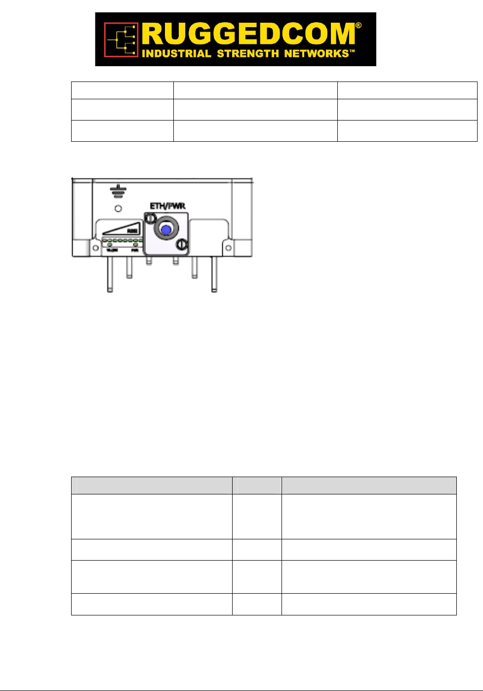
2.7 Physic a l De sc riptio n
TheWiN5200CPEhousingholdstheelectronicmodulesandtheconnectionpaneldetailed
below.
Figure 2-4: WIN5200 – Top View
Dimensions(HxWxDw/otheantenna):22cmx9.2cmx6cm
Weight:<1.5Kg
2.7.1 Physic a l Inte rfa c e s De sc riptio n
Theinterconnectionpanelholdstheexternalconnectorsusedtoconnecttheequipmenttothe
network,powersupplyandantennasasillustratedbelow.Theinterconnectionpanelholds
theconnectorsaslistedbelow.
Table 2-1: External Connectors
W iN 5 2 0 0 Product De scr ipt ion | 2 5
Name Description Connector Type
ETH + PWR Data and power from WiN1010 RJ-45
Grounding screw
Figure 2-5: Interconnection Panel
2.7.2 LED Indic a tio n De sc riptio n
TheLEDindicationsarelocatedonthebottompaneloftheoutdoorunit.TheCPEhasthe
followingLEDindications:
LINKQUALITYbardisplay–displaytheRSSIlevel
WLNK–wirelesslinkindication
PWR–powerokindication
TheLEDfunctionalityisdescribedinthetablebelow.
LEDs Color Description
WLNK is On Green CPE is connected with and receives
services from Base station (Network
Entry completed)
PWR is on Green CPE power is good
One bar LED is On (Least
significant)
Green 5dB ≤ SNR < 10dB
Two bar LEDs are On Green 10dB ≤ SNR < 15dB

W iN 5 2 0 0 Product De scr ipt ion | 2 6
Three bar LEDs are On Green 15dB ≤ SNR < 20dB
Four bar LEDs are On Green 20dB ≤ SNR < 24dB
Five bar LEDs are On Green SNR ≥ 24dB and RSSI < -75dBm
Six bar LEDs are On Green SNR ≥ 24dB and RSSI ≥ -75dBm
Seven bar LEDs are On Green SNR ≥ 24dB and RSSI ≥ -70dBm
Eight bar LEDs are On Green SNR ≥ 24dB and RSSI ≥ -60dBm
Only the 8th LED is On (Most
significant)
Green RSSI ≥ -20dBm (saturation)

W iN 5 2 0 0 Product De scr ipt ion | 2 7
3

W iN 5 2 0 0 Mount ing | 2 8
o unting

W iN 5 2 0 0 Mount ing | 2 9
3.1 G e ne ra l
TheCPEmountingkit,whichenablesseveralmountingoptionssuchasinthefollowing
examples:
1.Poles
2.Walls
Whenchoosingthemountinglocationfortheunit,considertheavailablemounting
structures,antennaclearance.
3.2 Site Surve y
MostwirelessnetworksincludemanyCPEsandBSTsinstalledinvariouslocationsinan
overlappingradio‐cellpattern.ItisimportanttopositioneachCPEatanoptimallocationand
theassignmentofitsradiochannels.Therefore,asitesurveybecomesanessentialfirststep
beforephysicallydeployingtheRuggedComsolution.
InstallationoftheCPEsrequiresabackhaultointerfacethecorporatenetworkorInternet.
ThisbackhaulconnectioncanbeanEthernet‐wiredconnection,awireless–connection,ora
thirdpartysolution.
ThesitesurveyshouldincludeadetailedplanningoftheWiMAXsystemdeployment.The
systemdeploymentplanshouldincludemountingpointsandtheroutesforthepowerand
backhaulcables.
Recom m en de d Site Requ ir em e nt s
ItishighlyrecommendedthattheWiN5200CPEsbemountedneartheedgeoftheroofofa
tallbuilding.TheWiN5200CPEsshouldbepointedinthedirectionoftheareatobecovered.
Toprovidemaximumcoverage,multipleWiN5200CPEscanbeinstalledonthesame
rooftop.However,itisimportanttoleavesomedistancebetweeneachunitinorderto
preventinterferencebetweentheunitsthemselves.Whenchoosingtheideallocation,itisalso
importanttotakeintoconsiderationtheoverallareatopology.

W iN 5 2 0 0 Mount ing | 3 0
3.3 Po le Mo unting
Selectamountinglocation.YoucanattachtheWiN5200toanypipeorpolewithdiameter
1.75”to10”.
3.4 Wa ll Mo unting
Selectamountinglocation.YoucanattachtheWiN5200toanywall,Outerwallispreferred
(typicallyonarooforhighlocationtoavoidinterferencefromotherbuildingsortrees).
EnsurethatthewallmountinstallationcanholdtheloadoftheODU.

W iN 5 2 0 0 Mount ing | 3 1
4

W iN 5 2 0 0 I nst alla t ion Pr oce du re | 3 2
nsta lla tio n Pro c e dure

W iN 5 2 0 0 I nst alla t ion Pr oce du re | 3 3
4.1 Sa fe ty Ha za rds
Warning
Installing the WiN5200 can pose a serious hazard. Be sure to take precautions to avoid the
following:
Exposure to high voltage lines during installation
Falls when working at heights or with ladders
Injuries from dropping tools
Contact with AC wiring
4.2 Too ls a nd C a ble s Re quire d fo r the Insta lla tio n
W iN 5 2 0 0 Et he rne t ODU CPE Requir em ent s:
IDU‐to‐ODUCat5eEthernetcable(100mMAX)andtwoRJ‐45plugconnectors
N ot e
The Cat5e Ethernet cable is not included. Please refer to "Appendix B – IDU to ODU cable specification"
for detailed technical specifications.
RJ‐45connectorscrimpingtool
Groundcablewithanappropriatetermination
Gen e ra l I nst alla t ion Tools:
FlatScrewdriver
Wrench
Driller
Hammer
AdjustableRatchetingSocketWrench
4.3 Insta lling the WiN5200
TheinstallationinvolvestheWiN5200andthemountingbracket.Themountingbracket
shouldbeinstalledatthefirstinstanceandtheWiN5200shouldbeinsertedintoit,asdetailed
inthefollowinginstructions.
W iN 5 2 0 0 I nst alla t ion Pr oce du re | 3 4
4.3.1 Po le Mo unting
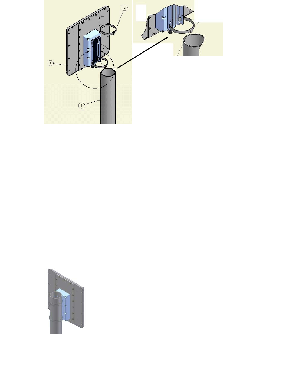
Figure 4-1: Pole Mounting
Followthestepslistedbelowtoinstalltheoutdoordeviceonapole
1.Selectamountinglocationonthepole
2.Slidethetwoadjustablehoseclampsalongthepoleviatheholesofthemountingbracket
oftheoutdoordevice
3.AdjustthetwoadjustablehoseclampsbythemeansofaAdjustableRatchetingSocket
Wrench
4.Attachoutdoordeviceusingthetwoadjustablehoseclampstothepole
5.FastentwoadjustablehoseclampsbythemeansofaAdjustableRatchetingSocket
Wrench
6.FastenthetwoadjustablehoseclampsbythemeansofaAdjustableRatchetingSocket
Wrench.
Figure 4-2: WiN5200 Pole Mounted
W iN 5 2 0 0 I nst alla t ion Pr oce du re | 3 5
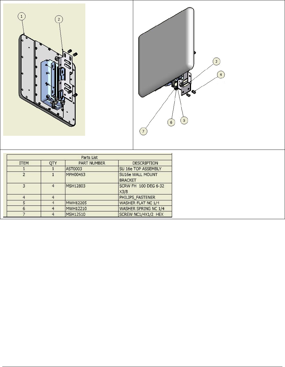
4.3.2 Wa ll Mo unt
Rear View
Front View
Figure 4-3: WiN5200 Wall Mount
FollowthestepslistedbelowtoinstalltheWiN5200onawall
1.Selectamountinglocationonthewall
2.Placethewallmountingbracketonthewallandmark4holes(2onthetopand2onthe
bottom)
3.Drill4holes(2onthetopand2onthebottom)forthefasteninginserts
4.InsertfasteninginsertstypeNC¼intotheholes
5.Insert4flatwashersand4springwashersand4screwstypeNS1/4X½HEX(2onthe
topand2onthedown)viatheholesonthemountingbracket
6.Attachthewallmountingbracketatthislocation

W iN 5 2 0 0 I nst alla t ion Pr oce du re | 3 6
7.Pressthescrewstilltheymatchtheinserts
8.Fastenthescrewswithascrewdriver
9.Useflatscrewdriver
10.InserttheWiN5200sothatthewallmountingbracketholesmatchtheholesofthe
mountingbracketofthedevice
11.Insertfourflatwashers,fourspringwashersandfourscrews(typeNC¼x½HEX)and
pressuntiltheymatchthetreadsoftheholesofthemountingbracket
12.Fastenthescrewswithascrewdriver
W iN 5 2 0 0 I nst alla t ion Pr oce du re | 3 7
4.4 C a ble C o nne c tio ns
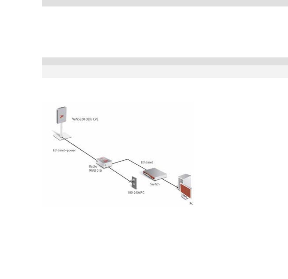
4.4.1 Insta lling the WiN1010 da ta a da pte r fo r WiN5200
TheWiN1010dataadapterisusedtopowertheWiN5200andtodistributedata.
TheWiN1010dataadapterisacombineddataandpoweradapterthatinterfacestothe
customer’sOutdoorUnitwirelessdevice.TheWiN1010dataadapterunitprovidesRJ‐45
inputconnectorsthatinclude10/100Base‐TtransformersforconnectiontoanIEEE802.3
(10/100Base‐T)compatibledevice.Theunitreceivespowerfrom100Vto240VACusingan
IEC‐320‐C14industrystandardconnector.
I m port a nt
ThepowersupplyACcordshouldbe3wires,18AWGminimum,withlengthlessthan4.5
m,safetycertifiedaccordingtonationalrules
AsingleoutputRJ‐45connectorprovides10/100Base‐Tdataandpowertotheoutdoorunit
overaCat5ecable.Thiscableservesthebi‐directionaltransferofdataandsignalingaswell
asapowerfeedtotheoutdoorequipment.
N ot e
The Cat5e Ethernet cable is not included. Please refer to "Appendix B – IDU to ODU cable specification"
for detailed technical specifications.
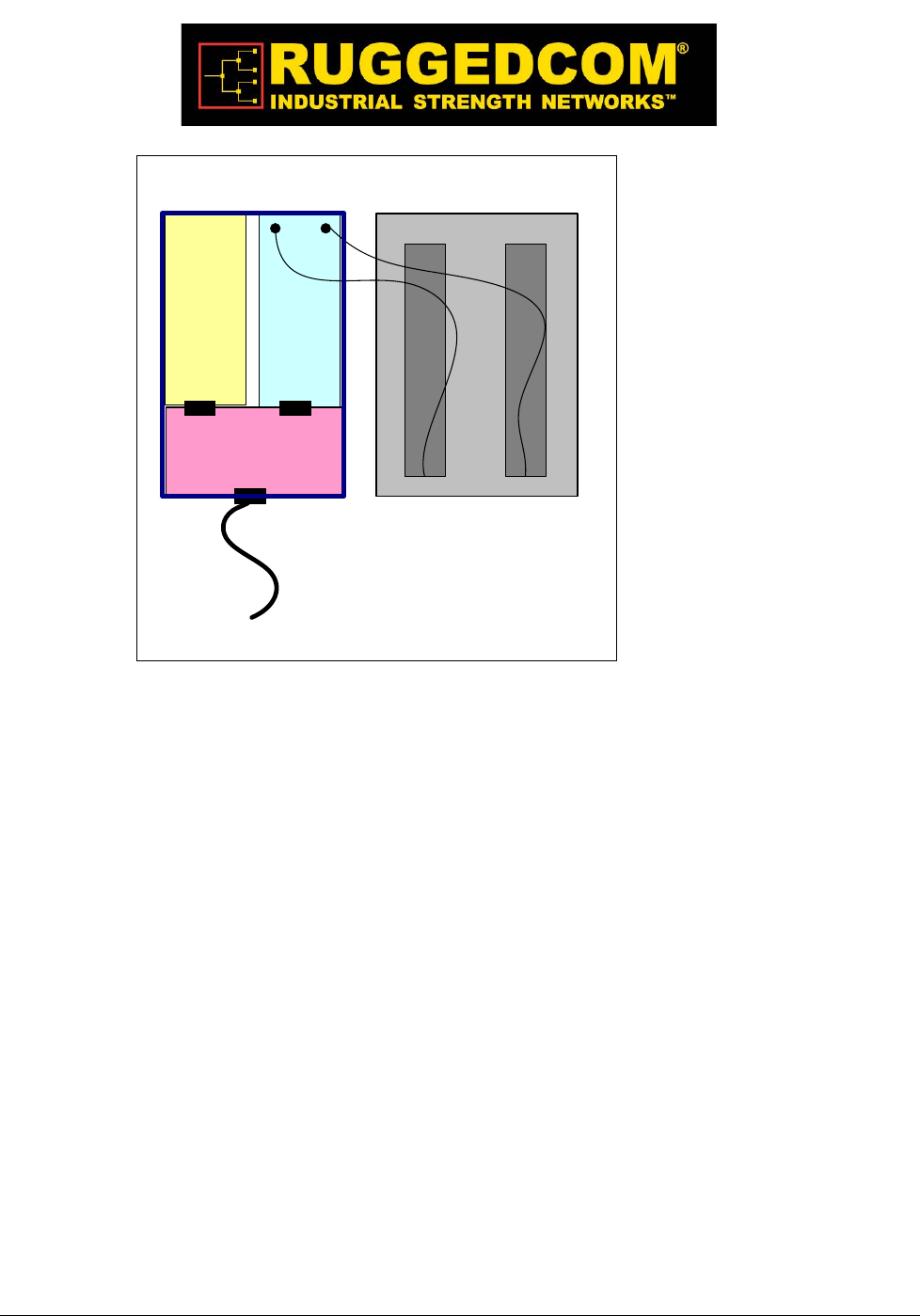
Theconnectionschemabelowillustratestheconnectionsbetweenthedevices.
Figure 4-4: WiN5200 Interconnection Schema
Conne ct t he W iN 5 2 0 0 t o W iN 1 0 1 0 Da t a Adapt e r
ConnectoveraCat5ecabletheEthernetportoftheWiN5200totheODUIFportofthe
WiN1010.
W iN 5 2 0 0 I nst alla t ion Pr oce du re | 3 8
N ot e
The Cat5e Ethernet cable is not included. Please refer to "Appendix B – IDU to ODU cable specification"
for detailed technical specifications.
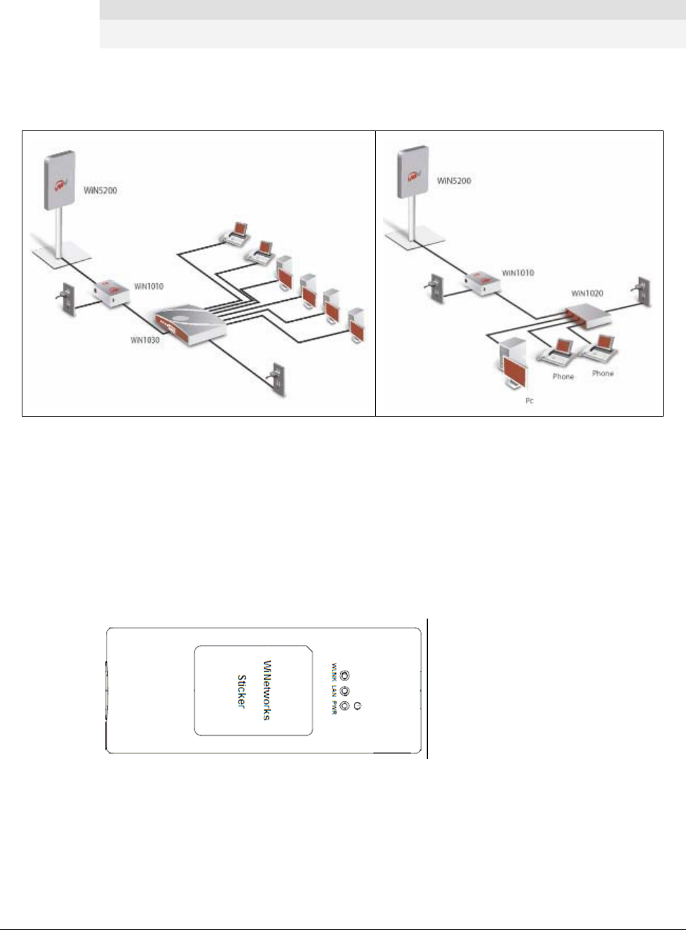
Conne ct t he W iN 1 0 1 0 da ta ada pte r t o a Sw it ch/ Rout er / PC
ConnectoveraCat5ecabletheEthernetportoftheoftheWiN1010dataadaptertoa10/100
Base‐TportofaSwitch/Router/PC.Figure4‐5illustratessomeconnectionoptions.
Figure 4-5: WiN1010 Data Adapter Connecting Options
Pow er Connect ion
ConnecttheWiN1010dataadaptertothe110V/220VACmainsusingthesuppliedcable.
BeforeconnectingtheWiN1010dataadaptertothemainoutletverifythatallsystem
componentsareproperlyinstalled.Makesurethatallcableconnectorsaresecurely
positionedintheappropriateports.
W iN 1 0 1 0 da ta a da pte r LED I ndica t ors
LEDsonthefrontpanelindicatethestatusofthedevice.
Figure 4-6: WiN1010 Data Adapter Front Panel
TheLEDsarelistedbyfunctioninthefollowingtable.
W iN 5 2 0 0 I nst alla t ion Pr oce du re | 3 9
Table 4-1: WiN1010 data adapter LED Description
WiN1010 data adapter LED Description
Name Color Description
PWR Green Input power is connected
LAN Green LAN link/activity display
WLNK Green Wireless link/activity display
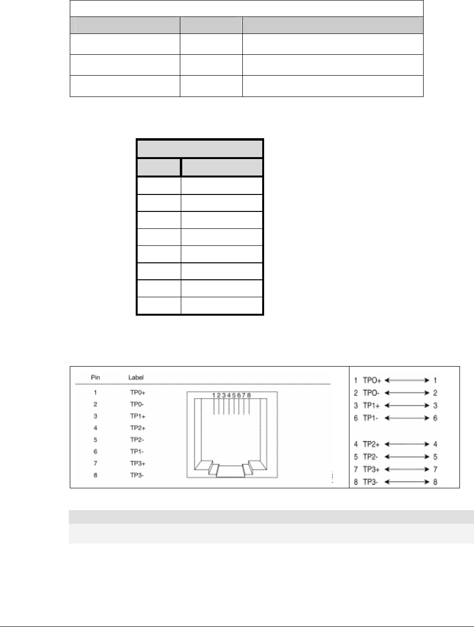
Table4‐2:ODUI/Fportpin‐out
ODU I / F - RJ-45
Pin # Description
1 ETH Data
2 ETH Data
3 ETH Data
4 + 48V
5 + 48V
6 ETH Data
7 RTN ( -)
8 RTN ( -)
Cable Pinout
EthernetCablePinout
Figure 4-7: Ethernet Cable RJ-45 Pinout
N ot e
The Cat5e Ethernet cable is not included. Please refer to "Appendix B – IDU to ODU cable specification"
for detailed technical specifications.

W iN 5 2 0 0 I nst alla t ion Pr oce du re | 4 0
5

W iN 5 2 0 0 Equipm e nt Configura t ion a n d M onit oring | 4 1
quipme nt C o nfig ura tion a nd
Mo nito ring

W iN 5 2 0 0 Equipm e nt Configura t ion a n d M onit oring | 4 2
5.1 Co nfig uring WiN5200 Ba sic Pa ra m e te rs
N ot e
The WiN5200 may be pre-configured in the lab before being sent for installation at the customer’s site.
In this case, this section can be skipped.
Aftercompletingtheinstallationprocess,thebasicparametersmustbeconfiguredtoensure
thattheunitoperatescorrectlyandcancommunicatewiththebasestation.Oncethebasic
parametershavebeenconfigured,additionalparameterscanberemotelyconfiguredviathe
wirelesslink.
1.connecttotheIPaddress192.168.254.251withthewebbrowserthroughtheEthernet
port
2.IntheLoginwindow,enterusername=vendor,password=vendorpass.
Figure 5-1: Login Screen
3.ChecktheWiN5000/5200isconfiguredtoworkinthecorrectfrequency.Todoso,choose
theCONFIGtabandthenchooseshowScanner.PresstheCALLbutton.The
commandliststhechannels(frequencyandbandwidthpairs)theWiN5000/5200sscanin
ordertocommunicatewiththebasestation.Thechannelvaluesaresetatthefactory.
Figure 5-2: showScanner screen
W iN 5 2 0 0 Equipm e nt Configura t ion a n d M onit oring | 4 3
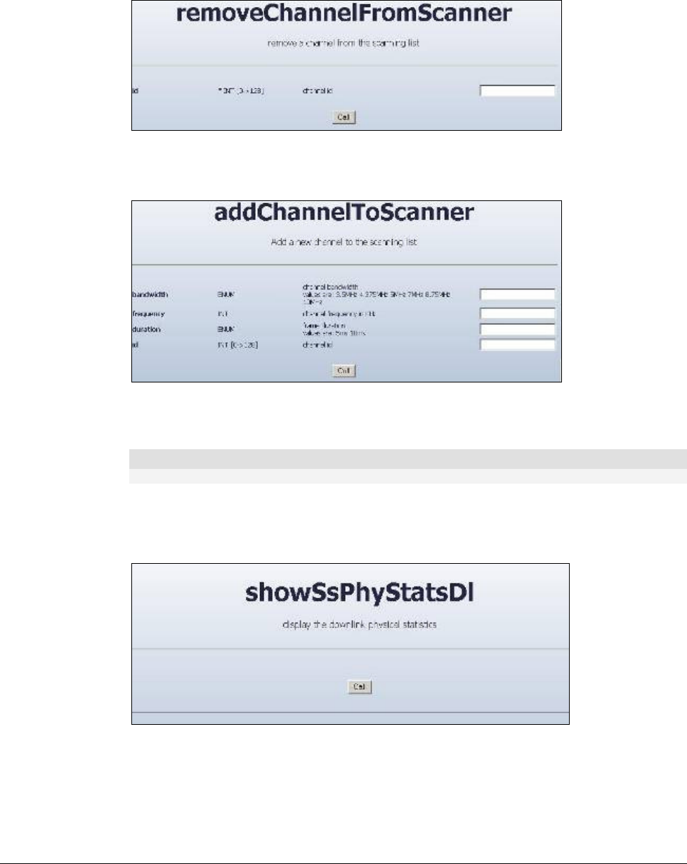
4.UsetheremoveChannelFromScannercommandtoremoveachannelfromthescanning
procedure.Intheidfield,entertheIDofthescannedchannel(theIDsareshowninthe
resultsoftheshowScanneroperation).
Figure 5-3: removeChannelfromScanner screen
5.Toaddachannelforscanningpurposes,selecttheaddChannelToScannercommand.
Figure 5-4: addChannelToScanner screen
Enterthebandwidthandthefrequency.AnIDwillbeallocatedautomatically.
N ot e
The frequency and bandwidth should match the cBST configuration
6.Todisplayphysicalstatisticsonthedownlink,chooseSStab,fromthemenuontheleft
handsideofthescreen,chooseshowSsPhyStatDl.PresstheCALLbutton.ChecktheSS
RSSIandCINRlevels.HittheCALLbuttontorefreshthescreen.
Figure 5-5: showSsPhyStatDl screen

W iN 5 2 0 0 Equipm e nt Configura t ion a n d M onit oring | 4 4
N ot e
This field is only valid when the CPE is synchronized with the cBST.
7. ChoosetheSStab,fromthemenuonthelefthandsideofthescreen,chooseshowSs.
PresstheCALLbutton.CheckiftheWiN5000/5200isinOPERATIONALstatus.
"OPERATIONAL" status means that the link is up.
Figure 5-6: showSsPhyStatDl screen
8.CheckthatalltheServiceflowsarecreatedbyusingtheshowSFmenu
5.2 Alig ning the CPE Ante nna
TheLINKQUALITYbardisplayislocatedonthebottompaneloftheoutdoorunit.TheLED
markedWLNKindicatesthatthewirelesslinkisactive,andislitwhentheCPEhas
completedtheNetworkEntryprocess.Thereare8LEDsthatindicatethequalityofthe
receivedsignal.ThehigherthenumberofLEDsthatareon,thebetterthequalityofthe
receivedsignal.
ThissectiondescribeshowtoaligntheCPEantennausingtheLINKQUALITYbardisplay.

W iN 5 2 0 0 Equipm e nt Configura t ion a n d M onit oring | 4 5
5.2.1 CPE Ante nna Alig nme nt Pro c e dure
PointtheantennatowardsthegeneraldirectionoftheBaseStation.
Verifythatthepowerindicationoftheunitison.
VerifythatatleastonegreenLEDoftheLINKQUALITYbardisplayison,indicating
thattheunitissynchronizedwiththebasestation.IftheCPEisnotsynchronizedwith
thebasestation,ensurethatallparametersareconfiguredproperly.IftheCPEisstillnot
synchronizedwiththebasestation,improvethequalityofthelinkbychangingthe
directionoftheantennaorbyplacingtheCPEatahigheroralternatelocation.
RotatetheCPEuntilthemaximumLinkQualityreadingisachieved.Ifyouencounter
prolongeddifficultyinachievingtheexpectedlinkquality,trytoimprovethereception
qualitybyplacingtheCPEatahigherpointorinanalternatelocation.
N ot e
Ensure that the front of the antenna is always facing the Base Station. However, in certain conditions,
such as when the line of sight to the Base Station is hampered, better reception may be achieved using
a reflected signal. In this case, the antenna is not necessarily directed toward the Base Station
SecuretheCPEfirmlytothepole.
N ot e
In some cases, the antenna may need to be tilted to ensure that the level at which the CPE receives
transmissions from the Base Station (and vice versa) is not too high. When all LINK QUALITY LEDS are
on. This indicates that the received signal level is too high (saturation). This must be avoided, preferably
by up-tilting the antenna. As a rule of thumb, if the CPE is located at a distance of less than 300 meters
from the Base Station, it is recommended to up-tilt the antenna by approximately 10° to 15°
Table 3: LINK QUALITY Bar LEDs Functionality
Bar LEDs SNR
WLNK is On CPE is connected with and receives services
from Base station (Network Entry completed)
One bar LED is On (Least
significant)
5dB ≤ SNR < 10dB
Two bar LEDs are On 10dB ≤ SNR < 15dB
Three bar LEDs are On 15dB ≤ SNR < 20dB
Four bar LEDs are On 20dB ≤ SNR < 24dB
Five bar LEDs are On SNR ≥ 24dB and RSSI < -75dBm

W iN 5 2 0 0 Equipm e nt Configura t ion a n d M onit oring | 4 6
Bar LEDs SNR
Six bar LEDs are On SNR ≥ 24dB and RSSI ≥ -75dBm
Seven bar LEDs are On SNR ≥ 24dB and RSSI ≥ -70dBm
Eight bar LEDs are On SNR ≥ 24dB and RSSI ≥ -60dBm
Only the 8th LED is On (Most
significant)
RSSI ≥ -20dBm (saturation)
Figure 5-7:Example of RSSI Scan behavior
5.2.2 Link Indic a tio n
AnotherfunctionofthisLEDistoindicatewhetherornottheSShavealinkwiththeBS.
Blink‐thelinkisdown.
Constantlight–thelinkisup.

W iN 5 2 0 0 Equipm e nt Configura t ion a n d M onit oring | 4 7
6

W iN 5 2 0 0 Ma nagem ent | 4 8
a na g e me nt

W iN 5 2 0 0 Ma nagem ent | 4 9
6.1 G e ne ra l
TheCPEscanbemonitoredandcontrolledwithastandalonePCorthroughamanagement
system(WiNMS)usingthebackhaulinterface.Themonitoringandcontrolcapabilitiesare
similarinbothcasesbuttheinterfacemayappeardifferent.Thissectionwilldetailallthe
monitoringandcontrolcapabilitiesandthenwillspecifywhichofthemareavailablethrough
eachtypeofinterface.
ThelocalPCcanconnecttotheinternalWEBserverusingHTTP.
TheCPEshaveastandardMIBIIandproprietyMIB.
ManagementoftheCPEdeviceshalluseSNMP.
Alllevelsofmanagementaresecuredbypasswords.
TherearenolocaldisplaysontheCPEs.Alltheindicationswillhavetobemonitoredviathe
managementsystem(WiNMS).
6.2 SW Downlo a d/ Upg ra de
SoftwarecanbeloadedintotheCPEinseveralways:
UsingalocalPC(connectedtothenearbyswitch)
RemotelyusingSNMP(overthebackhaulinterface)
RemotelyusingFTP
TheCPEsupportsacompleterollbackoptionincasetheupgradedoesnotwork.

W iN 5 2 0 0 Ma nagem ent | 5 0
Figure 6-1: SoftwareUpgrade Screen
FilltheFTPserverIPaddressintheHostIpAddressfield
FillthedirectoryinwhichthenewSWfilesarelocatedintheFileDirectoryfield
Inthisdirectorythereshouldbe<filename>.pkgfile
Fillinthefilenameofthe.pkgfileinthePackageFileNamefield
FillintheusernameandpasswordoftheFTPserverintheappropriatefields
Pressthecallbutton
Waitfortheupgradeprocesstocomplete
6.3 We b- pa g e Ma na g e m e nt
Themonitoredandcontrolledparametersarealsoavailablethroughweb‐pageinterface.
PleaserefertoSection5EquipmentConfigurationandMonitoringforbasicconfiguration
andmonitorscreens.
Themostcommonoperatingcommandsarelistedinthefollowingtable.Forsakeof
conveniencethecommandsarelistedbytabsofthesoftware.
Table 6-1: List of Commands - Configuration

W iN 5 2 0 0 Ma nagem ent | 5 1
Tab Command Function Notes
Conf ShowTxRxparam Shows the Transmit and
Receive parameters
showscanner Shows the scanning list of
channels/frequencies
addChannelToScanner Adds a new channel to the
scanner
removeChannelfromScanner Removes a channel from
the scanning list
clearScannerChannel Resets all channel
scanners
showMacUl Shows theMac Uplink
configuration
showMacDl Shows the Mac Downlink
configuration
showRfRx Shows the Radio Receiver
Frequency configuration
showRfTx Shows the Radio
Transmitter Frequency
configuration
showLinkAdaptationDl Shows the Downlink
Adaptation information
Table 6-2: List of Commands - SS
Tab Command Function Notes
SS ssPhyStatsDl Shows the physical status
of the device
startSs Starts the 802.16 MAC
resetSs Stops and resets the
802.16 MAC
showSs Shows subscriber station
information

W iN 5 2 0 0 Ma nagem ent | 5 2
Table 6-3: List of Commands - Tools
Tab Command Function Notes
Tools showMacAddress Shows the mac address
showMSGProtocol
showVersion Shows the system
version
showRegisteredMsg Shows registered Msg
showIPAddressTable
setIPAddresTable Set and configure
subscriber’s IP address
showAutorizedManager Shows a list of
authorized managers by
IP address
showAutorizedManager Set a list of authorized
managers
addAutorizedManager Add authorized manager
to the list
addAutorizedManager Delete authorized
manager from the list
addSnmpAccess Add SNMP access by
IP address
DeleteSnmpAccess Delete SNMP access by
IP address
Filelist Shows the list of files
FileUpload Upload files from the
computer
FileDownload Download files to the
computer
Trapenable Enables traps
TarpGetActive Sends all active traps
TrapIpAddress Sets trap IP address
AddTrapIpAddress Add trap IP address
deleteTrapIpAddress Delete trap IP address

W iN 5 2 0 0 Ma nagem ent | 5 3
Tab Command Function Notes
TrapConfig Configure a trap
showTrap Shows trap parameters
SoftwareUpgrade Shows software upgrade
parameters
showPkgFiles Shows package file
indoemation
runMainPkfFile Runs Main Package File
Following the download of
a new software package
this can be set as the main
package.
If the last update is not
helpful you can set it as
secondary package and
restart the base station
from the previous software
version
runSecondaryPkfFile Runs Secondary Package
File
After reset the station
starts from secondary
package file
setSecondaryasMain Sets Secondary File As
Main File
If the last update is not
helpful you can set it as
secondary package and
restart the base station
from the previous software
version
swapPkgFiles Swaps Package Files Toggles between main and
secondary package and
saves
Restart Restarts Subscriber’s
Station

W iN 5 2 0 0 Ma nagem ent | 5 4
6.4 SNMP Ma na g e m e nt
TherearetwoMIBtypesavailableintheCPE:
thestandardMIBII(RFC1213)
theprivateMIB
Table6‐4describestheCPEManagedParameters.
Table 6-4: Subscriber Station Parameters
Parameter Description MI B Type Remarks
Location site
+ Contact details
MIB II
Cell ID Activity
(Connected/Disconnected),
Speed (10/100/1000), Duplex
(Full/Half), IP Address,
Private
Data Interface
Status
MIB II
Temperature temperature inside the case Private
Software Version all Modules software’s versions Private
Uptime on time from power up Private
Number of
registered SU
Private
SU MAC
Addresses
Private
SU Type Private
Radio Status Transmit: On/Off
Frequency: configured radio
frequency
Configured BW/FFT
Transmit power
Private
TX Counter Number of transmit packets Private
RX Counter Number of receive packets Private

W iN 5 2 0 0 Appendix A – Pr oduct Spe cificat ion | 5 5

List of Acronyms
W iN 5 2 0 0 Appendix A – Pr oduct Spe cificat ion | 5 6
Radio and Modem:
Frequency WiN5125-XX, WiN5225: 2496 MHz
to 2690 MHz
WiN5237: 3650 MHz to 3700 MHz
Radio Access Method IEEE802.16-2005 (16e OFDMA)
Operation Mode TDD
Compatibility WiN52XX-2: Wave 2 Profile
(MIMO)
Channel Bandwidth WiN5125-XX, WiN5225: 5 MHz,
7MHz, 10 MHz
WiN5137-XX, WiN5237: 5 MHz
,7MHz, 10 MHz
Frequency Resolution 0.25 MHz
Antenna Support Integral/External
Number of Antennas 2
Antenna Diversity Support STC/MIMO
Output Power [P1dB]
2W
Output Power (average)
24 dBm +/-1dB maximum
TPC 45dB
FFT/Modulation 1024/512 FFT points;
QPSK, 16QAM, 64QAM
FEC Convolution Code and Turbo Code
Dynamic range RX: -100dBm :-20 dBm
TX: -20dBm : +24 dBm
Data Communication (Through indoor unit):
Ethernet Standard
Compliance
IEEE 802.3 CSMA/CD
Ethernet Port 10/100 Mbps, Half/Full Duplex with
Auto Negotiation
VLAN Support IEEE 802.1Q
Traffic Classification IEEE 802.1p
DiffServ (DSCP)
Max User Throughput DL: 12Mbps, UL: 6Mbps
Ordering Information:
Part Number WiN52XX-2-02-W
XX – Frequency range See frequency table for details
Indoor Unit (ETH) Compatibility:
WiN1010 Data Adapter
Configuration and Management:
Local Management Telnet
SNMPv2
Web Browser
Remote Management SNMPv2 over wireless via the base
station
SNMP Agent SNMP ver 2 client: MIB II (RFC
1213), Private Win-Max MIBs
Authentication EAP-TTLS:
Device: X509 digital certificate
User: MS-CHAP
Software Upgrade FTP
Remote Configuration FTP
Mechanical, Electrical and Environmental:
Dimensions (w/o the
antenna) [H, W, D]
224 x 92 x 61 mm
Weight 1.5 kg
Power Source 48VDC from the indoor unit over
the indoor-outdoor cable
Power Consumption 17W maximum
Operating Temperature -40C to +55C
Operating Humidity 5%-95% non condensing, Weather
protected
Standards Compliance:
EMC FCC part 15, subpart B, class B
ETSI EN 301489-1/4
Safety TUV-UL 60950-1
EN 60950-1
Radio FCC Part27
ETSI EN 302 326-1/2/3
Environmental
Enclosure
ETS 300 019
Type 3R (IP66)

List of Acronyms
W iN 5 2 0 0 Appendix B – I DU t o OD U Ca ble Spe cifica t ions | 5 7
List of Acronyms
W iN 5 2 0 0 Appendix B – I DU t o OD U Ca ble Spe cifica t ions | 5 8
ppe ndix B – IDU to O DU Ca b le
Spe c ific a tio ns

List of Acronyms
W iN 5 2 0 0 List of Acron ym s | 5 9

List of Acronyms
W iN 5 2 0 0 List of Acron ym s | 6 0
ist o f Ac ro nyms
AAA Authentication Authorization Accounting
AES Advanced Encryption Standard
ALG Application-Level Gateway
AMC Adaptive Modulation and Coding
API Application Programming Interface
ARPU Average Revenue Per Unit
ASN Access Service Network
ASP Application Service Provider
ATPC Automatic Transmit Power Control
BE Best Effort
BPSK Binary Phase Shift Keying
BST Base Station
BWA Broadband Wireless Access
CAPEX Capital Expenditure
CBST Compact Base Station
CPE Customer Premise Equipment
DES Data Encryption Standard
DHCP Dynamic Host Configuration Protocol
DMZ Demilitarized Zone
DNS Domain Name System
DSL Digital Subscriber Line
DSLAM Digital Subscriber Line Multiplexer
DVB Digital Video Broadcast
EAP Extensible Authentication Protocol
ErtPS Extended Real-Time Polling Service

List of Acronyms
W iN 5 2 0 0 List of Acron ym s | 6 1
FCAPS Functionality Configuration Accountability Performance
Security
FFT Fast Fourier Transfer
FTP File Transfer Protocol
FUSC Fully Used Sub-Channelization
FXS Foreign Exchange Subscriber
GW Gateway
HA Home Agent
HTTP HyperText Transport Protocol
IAD Integrated Access Device
ICMP Internet Control Message Protocol
IDU Indoor Units
IEEE Institute of Electronic and Eclectic Engineers
IGMP Internet Group Multicast Protocol
IMS IP Multimedia System
IOS Internetwork Operating System
IP Internet Protocol
IPSec IP Security
LAN Local Area Network
LOS Line-of-sight
MAC Media Access Control
MAI Multiple Access Interference
MAN Metropolitan Area Network
MGCP Media Gateway Control Protocol
MIMO Multiple-Input, Multiple-Output
MIP Mobile IP
MOS4 Mean Opinion Score (voice quality 1-5)
MOS5 Mean Opinion Score (voice quality 1-5)

List of Acronyms
W iN 5 2 0 0 List of Acron ym s | 6 2
MSG Multi-Service Gateways
MTU Maximum Transmission Unit
MTU Multiple Tenant Unit
NAP Network Access Provider
NAPT Network Address Port Translation
NEBS Network Equipment Building System
NMS Network Management System
NLOS Non-line-of-sight
nrtPS Non-Real Time Polling Service
NSP Network Service Provider
NVoD Near Video on Demand
NWG Network Working Group
OAM Operations and Maintenance
ODU Outdoor Units
OEM Original Equipment Manufacturer
OFDM Orthogonal Frequency Division Multiplexing
OFDMA Orthogonal frequency division multiple access
OPEX Operational Expenditure
P-CSCF Proxy - Call Session Control Function
PDA Personal Digital Assistant
PDF Portable File Format
PMIP Proxy Media IP
POP Point of Presence
POP3 Post Office Protocol 3
POTS Plain Old Telephony System
PPP Point-to-Point Protocol
PPTP Point-to-Point Tunneling Protocol
PSK Phase Shift Keying

List of Acronyms
W iN 5 2 0 0 List of Acron ym s | 6 3
PSTN Public Switched Telephone Network
PUSC Partially used sub-channelization
PVR Personal Video Recorder
QAM Quadrature Amplitude Modulation
QoS Quality of Service
QPSK Quadrature Phase Shift Keying
RC Return Channel
RF Radio Frequency
RG Residential Gateway
RIP Routing Information Protocol
ROI Return of Investment
rtPS Real-Time Polling Service
SF Service Flow
SIP Session Initiation Protocol
SLA Service Level Agreements
SNMP Simple Network Management Protocol
S-OFDMA Scalable Orthogonal frequency division multiple access
SOHO Small Office/Home Office
SS Subscribers
STB Set Top Box
STC Space-time coding
SU Subscriber Unit
TCP Transmission Control Protocol
TDD Test Driven Design
TFTP Trivial File Transfer Protocol
TMN Telecommunication Management Sysytem
UDP User Datagram Protocol
UGS Unsolicited Grant Service

List of Acronyms
W iN 5 2 0 0 List of Acron ym s | 6 4
URL Universal Resource Locator
USB Universal Serial Bus
VoD Video on Demand
VoIP Voice over IP
VPN Virtual Private Network
WAN Wide Area Network
WiMAX Worldwide Interoperability for Microwave Access
WLL Wireless Local Loop
WMAN Wireless Metropolitan Area Networks