Siemens Communications AP36V1B HiPath Wireless AP, Altitude 450, Altitude 451 User Manual Part 2
Siemens Communications, Inc. HiPath Wireless AP, Altitude 450, Altitude 451 Part 2
Contents
- 1. User Manual Part 1
- 2. User Manual Part 2
- 3. User's Guide
- 4. User's guide
- 5. users guide
User Manual Part 2

hwc_controlleravailmobility.fm
A31003-W1050-U100-2-7619, March 2008
HiPath Wireless Controller, Access Points and Convergence Software V5 R1 , C20/C2400 User Guide 251
Availability, mobility, and controller functionality
Availability overview
7 Availability, mobility, and controller functionality
This chapter describes the availability and mobility concepts, including:
•Availability overview
•Mobility manager
•Defining management users
•Configuring network time
•Configuring Check Point event logging
•Enabling SNMP
•Using controller utilities
•Configuring Web session timeouts
The HiPath Wireless Controller provides additional functionality including:
• Availability – Maintains service availability in the event of a HiPath Wireless
Controller outage
• Mobility – Allows multiple HiPath Wireless Controllers on a network discover
each other and exchange information about a client session. A maximum of
up to 12 controllers can be linked to allow users to transparently roam across
controllers in the mobility domain.
7.1 Availability overview
The HiPath Wireless Controller, Access Points and Convergence Software
system provides this feature to maintain service availability in the event of a
HiPath Wireless Controller outage.

Availability, mobility, and controller functionality
hwc_controlleravailmobility.fm
Availability overview
A31003-W1050-U100-2-7619,March 2008
252 HiPath Wireless Controller, Access Points and Convergence Software V5 R1 , C20/C2400 User Guide
The availability feature links two HiPath Wireless Controllers as a pair, to share
information about their Wireless APs. If one controller fails, its Wireless APs are
allowed to connect to the backup controller. The second HiPath Wireless
Controller provides the wireless network and a pre-assigned VNS for the Wireless
AP.
Note: During a failover event, the maximum number of failover APs a backup
controller can accommodate is equal to the maximum number of APs supported
by the hardware platform.
Note: Wireless APs that attempt to connect to a backup controller during a
failover event are assigned to the VNS that is defined in the system’s default AP
configuration provided the administrator has not assigned the failover Wireless
APs to one or more VNSs. If a system default AP configuration does not exist for
the controller (and the administrator has not assigned the failover Wireless APs
to any VNS), the APs will not be assigned to any VNS during the failover.
A HiPath Wireless Controller will not accept a connection by a foreign AP if the
HiPath Wireless Controller believes its availabilitty partner controller is in service.
Also, the default AP configuration assignment is only applicable to new APs that
failover to the backup controller. Any AP that has previously failed-over and is
already known to the backup system will receive the configuration already
present on that system.
For more information, see Section 4.5.7, “Configuring the default Wireless AP
settings”, on page 128.
From the viewpoint of a Wireless AP, if a HiPath Wireless Controller or the
connection to it fails, the Wireless AP begins its discovery process. The Wireless
AP is directed to the appropriate backup controller of the pair. This connection
may require the Wireless AP to reboot. Users on the Wireless AP must log in
again and be authenticated on the second HiPath Wireless Controller.
Note: The availability feature provides APs with a list of interfaces to which the
AP should attempt to automatically connect to when a connection with an active
controller link is lost. The provided list identifies the local active interfaces
(enabled on the primary and backup controllers) for the active controller as well
as the active interfaces for the backup controller. The list is sorted by top-down
priority. If the active link is lost (poll failure), the AP automatically scans (pings) all
addresses in its availability interface list. The AP will then connect to the highest
priority interface that responds to its probe.

hwc_controlleravailmobility.fm
Availability, mobility, and controller functionality
Availability overview
A31003-W1050-U100-2-7619, March 2008
HiPath Wireless Controller, Access Points and Convergence Software V5 R1 , C20/C2400 User Guide 253
7.1.1 Availability prerequisites
Before you begin, ensure you have completed the following:
•Choose the primary and secondary HiPath Wireless Controllers.
•Verify the network accessibility for the TCP/IP connection between the two
controllers. The availability link is established as a TCP session on port
13907.
•Set up a DHCP server for AP subnets to support Option 78 for SLP, so that it
points to the IP addresses of the physical interfaces on both HiPath Wireless
Controllers.
Note: You should also confirm that the Poll Timeout parameter on the AP
Properties page is set to its default value i.e., 15 (seconds). For more
information, see Section 4.5.2, “Modifying a Wireless AP’s properties”, on page
90.
If the Poll Timeout value is less than 15 (seconds), the Wireless AP failover will
not succeed because the secondary controller will not be ‘ready’ to accept the
failover APs. The secondary controller takes around 12 to 14 seconds after the
primary controller goes down to be ‘ready’ to accept the failover Wireless APs.
If the Poll Timeout value is more than 15 (seconds), the Wireless APs failover
will be unnecessarily delayed, because the Wireless APs will continue polling the
primary controller even though the secondary controller is ‘ready’ to accept them
as the failover APs.
Now set up each HiPath Wireless Controller separately. One method is as
follows:
1. On the AP Registration page, set up each HiPath Wireless Controller in
Stand-alone Mode.
2. On the Topology tab, define a VNS on each HiPath Wireless Controller with
the same SSID. The IP addresses must be unique. For more information,
Section 6.3, “Topology for a VNS”, on page 164. A HiPath Wireless Controller
C20/C2400 VLAN Bridged VNS can permit two controllers to share the same
subnet (different IP addresses). This setup provides support for mobility users
in a VLAN Bridged VNS.
3. On both HiPath Wireless Controllers, set the Registration Mode to Allow only
approved so that no more Wireless APs can register unless they are
approved by the administrator.
4. On the AP Registration page, enable the two HiPath Wireless Controllers as
an availability pair.

Availability, mobility, and controller functionality
hwc_controlleravailmobility.fm
Availability overview
A31003-W1050-U100-2-7619,March 2008
254 HiPath Wireless Controller, Access Points and Convergence Software V5 R1 , C20/C2400 User Guide
5. On each HiPath Wireless Controller, on the Access Approval page, check
the status of the Wireless APs and approve any APs that should be
connected to that controller.
System AP defaults can be used to assign a group of VNSs to the foreign
APs:
•If the APs are not yet known to the system, the AP will be initially
configured according to AP default settings. To ensure better transition in
availability, it is recommended that the AP default settings match the
desired VNS assignment for failover APs.
•AP assignment to VNSs according to the AP default settings can be
overwritten by manually modifying the AP VNS assignment. (For
example, select and assign each VNS that the AP should connect to.)
•If specific foreign APs have been assigned to a VNS, those specific
foreign AP assignments are used.
An alternate method to setting up APs includes:
1. Add each Wireless AP manually to each HiPath Wireless Controller.
2. On the AP Properties page, click Add Wireless AP.
3. Define the Wireless AP, and then click Add Wireless AP.
Manually defined APs will inherit the default AP configuration settings.
Caution: If two HiPath Wireless Controllers are paired and one has the Allow
All option set for Wireless AP registration, all Wireless APs will register with
that HiPath Wireless Controller.
To set the primary or secondary HiPath Wireless Controllers for availability:
1. From the main menu, click Wireless AP Configuration. The Wireless APs
page is displayed.
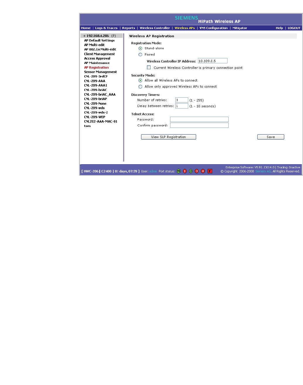
2. In the left pane, click AP Registration. The Wireless AP Registration page
is displayed.
hwc_controlleravailmobility.fm
Availability, mobility, and controller functionality
Availability overview
A31003-W1050-U100-2-7619, March 2008
HiPath Wireless Controller, Access Points and Convergence Software V5 R1 , C20/C2400 User Guide 255
3. To enable availability, select the Paired option.
4. Do one of the following:
•For a primary controller, in the Wireless Controller IP Address box, type
the IP address of the physical port of the secondary HiPath Wireless
Controller. This IP address must be on a routable subnet between the two
HiPath Wireless Controllers.
•For a secondary controller, in the Wireless Controller IP Address box,
type the IP address of the Management port or physical port of the
primary HiPath Wireless Controller.
5. Do one of the following:
•To set this HiPath Wireless Controller as the primary connection point,
select the Current Wireless Controller is primary connect point
checkbox.
•To set this HiPath Wireless Controller as the secondary connection point,
clear the Current Wireless Controller is primary connect point
checkbox.
If the Current Wireless Controller is primary connect point checkbox is
selected, the specified controller waits for a request. If the Current Wireless
Controller is primary connect point checkbox is cleared, the specified
controller sends a connection request. Confirm that one controller has this

Availability, mobility, and controller functionality
hwc_controlleravailmobility.fm
Availability overview
A31003-W1050-U100-2-7619,March 2008
256 HiPath Wireless Controller, Access Points and Convergence Software V5 R1 , C20/C2400 User Guide
checkbox selected, and the second controller has this checkbox cleared,
since improper configuration of this option will result in incorrect network
configuration.
6. To set the security mode for the HiPath Wireless Controller, select one of the
following options:
• Allow all Wireless APs to connect – If the HiPath Wireless Controller
does not recognize the serial number, it sends a default configuration to
the Wireless AP. Or, if the HiPath Wireless Controller recognizes the
serial number, it sends the specific configuration (port and binding key)
set for that Wireless AP.
• Allow only approved Wireless APs to connect – If the HiPath Wireless
Controller does not recognize the serial number, the operator is prompted
to create a configuration. Or, if the HiPath Wireless Controller recognizes
the serial number, it sends the configuration for that Wireless AP.
Note: During the initial setup of the network, it is recommended to select
the Allow all Wireless APs to connect option. This option is the most
efficient way to get a large number of Wireless APs registered with the
HiPath Wireless Controller.
Once the initial setup is complete, it is recommended that the security
mode is reset to the Allow only approved Wireless APs to connect
option. This option ensures that no unapproved Wireless APs are allowed
to connect. For more information, see Section 4.5, “Configuring Wireless
AP settings”, on page 87.
7. To save your changes, click Save.
Note: When two HiPath Wireless Controllers have been paired as described
above, each HiPath Wireless Controller's registered Wireless APs will appear
as foreign on the other controller in the list of available Wireless APs when
configuring a VNS topology.
7.1.2 Viewing the Wireless AP availability display
For more information, see Section 10.1.1, “Viewing the Wireless AP availability
display”, on page 295.
hwc_controlleravailmobility.fm
Availability, mobility, and controller functionality
Availability overview
A31003-W1050-U100-2-7619, March 2008
HiPath Wireless Controller, Access Points and Convergence Software V5 R1 , C20/C2400 User Guide 257
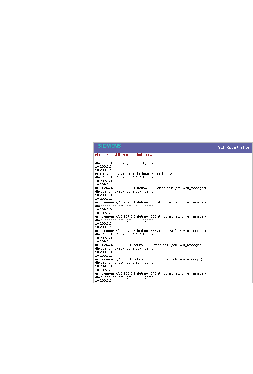
7.1.3 Viewing SLP activity
In normal operations, the primary HiPath Wireless Controller registers as an SLP
service called ac_manager. The controller service directs the Wireless APs to the
appropriate HiPath Wireless Controller. During an outage, if the remaining HiPath
Wireless Controller is the secondary controller, It registers as the SLP service
ru_manager.
To view SLP activity:
1. From the main menu, click Wireless AP Configuration. The Wireless APs
page is displayed.
2. In the left pane, click AP Registration. The Wireless AP Registration page
is displayed.
3. To confirm SLP registration, click View SLP Registration. A pop-up page
displays the results of the diagnostic slpdump tool, to confirm SLP
registration.
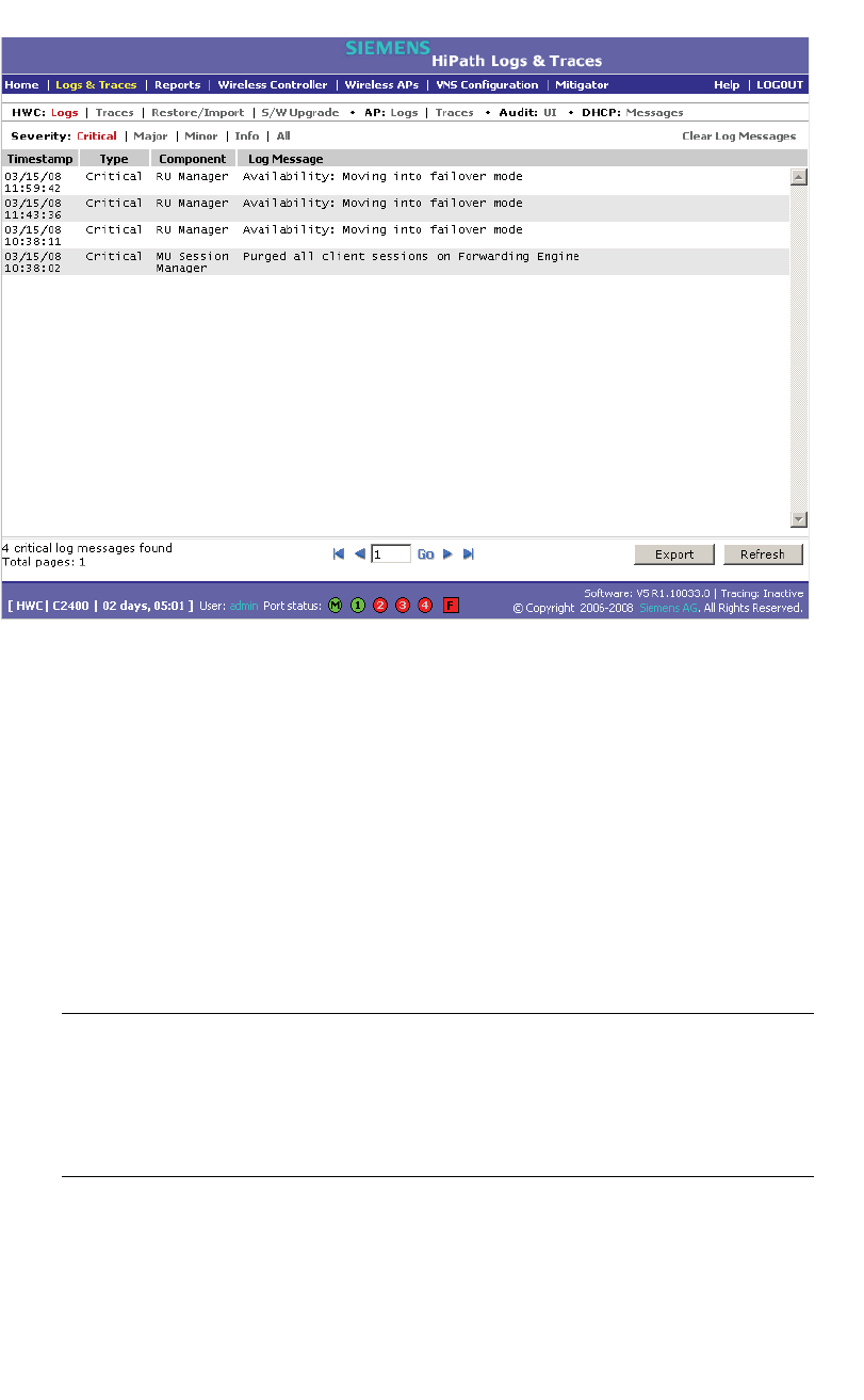
7.1.4 Events and actions during a failover
If one of the HiPath Wireless Controllers in a pair fails, the connection between
the two HiPath Wireless Controllers is lost. This triggers a failover mode
condition, and a critical message is displayed in the information log of the
remaining HiPath Wireless Controller.
Availability, mobility, and controller functionality
hwc_controlleravailmobility.fm
Availability overview
A31003-W1050-U100-2-7619,March 2008
258 HiPath Wireless Controller, Access Points and Convergence Software V5 R1 , C20/C2400 User Guide
After the Wireless AP on the failed HiPath Wireless Controller loses its
connection, it will try to connect to all enabled interfaces on both controllers
without rebooting. If the Wireless AP is unsuccessful, it will begin the discovery
process. If the Wireless AP is not successful in connecting to the HiPath Wireless
Controller after five minutes of attempting, the Wireless AP will reboot.
If the AP is assigned to different VNSs on the two controllers, it will reboot.
Because of the pairing of the two HiPath Wireless Controllers, the Wireless AP
will then register with the other HiPath Wireless Controller.
All user sessions using the AP that fails over will terminate unless the Maintain
client sessions in event of poll failure option is enabled on the AP Properties
tab or AP Default Settings page.
Note: A Wireless AP connects first to a HiPath Wireless Controller registered as
ac_manager and, if not found, then seeks an ru_manager. If the primary HiPath
Wireless Controller fails, the secondary one registers as ru_manager. This
enables the secondary HiPath Wireless Controller to be found by Wireless APs
after they reboot.
When the Wireless APs connect to the second HiPath Wireless Controller, they
will be assigned to the VNS that is defined in the system’s default AP
configuration. The wireless device users will log in again and be authenticated on
the second HiPath Wireless Controller.

hwc_controlleravailmobility.fm
Availability, mobility, and controller functionality
Mobility manager
A31003-W1050-U100-2-7619, March 2008
HiPath Wireless Controller, Access Points and Convergence Software V5 R1 , C20/C2400 User Guide 259
When the failed HiPath Wireless Controller recovers, each HiPath Wireless
Controller in the pair goes back to normal mode. They exchange information that
includes the latest lists of registered Wireless APs. The administrator must
release the Wireless APs manually on the second HiPath Wireless Controller, so
that they may re-register with their home HiPath Wireless Controller. Foreign APs
can now all be released at once by using the Foreign button on the Access
Approval page to select all foreign APs, and then clicking Released.
To support the availability feature during a failover event, administrators need to
do the following:
1. Monitor the critical messages for the failover mode message, in the
information log of the remaining HiPath Wireless Controller (in the Reports
and Displays section of the HiPath Wireless Controller).
2. After recovery, on the HiPath Wireless Controller that did not fail, select the
foreign Wireless APs, and then click Release on the Access Approval page.
7.2 Mobility manager
The HiPath Wireless Controller, Access Points and Convergence Software
system allows multiple HiPath Wireless Controllers (up to 12) on a network to
discover each other and exchange information about a client session. This
technique enables a wireless device user to roam seamlessly between different
Wireless APs on different HiPath Wireless Controllers.
The solution introduces the concept of a mobility manager, where one HiPath
Wireless Controller on the network is designated as the mobility manager and all
others are designated as mobility agents.
The wireless device keeps the IP address, VNS assignment, and filtering rules it
received from its home HiPath Wireless Controller—the HiPath Wireless
Controller that it first connected to. The VNS on each HiPath Wireless Controller
must have the same SSID and RF privacy parameter settings.
For the mobility manager you have two options:
•Rely on SLP with DHCP Option 78
•Define at the agent the IP address of the mobility manager. By explicitly
defining the IP address, the agent and the mobility manager are able to find
each other directly without using the SLP discovery mechanisms. Direct IP
definition is recommended in order to provide tighter control of the registration
steps for multi-domain installations.
The HiPath Wireless Controller designated as the mobility manager:
•The mobility manager is explicitly identified as the manager for a specific
mobility domain. Agents will connect to this manager to establish a mobility
domain.

Availability, mobility, and controller functionality
hwc_controlleravailmobility.fm
Mobility manager
A31003-W1050-U100-2-7619,March 2008
260 HiPath Wireless Controller, Access Points and Convergence Software V5 R1 , C20/C2400 User Guide
•Defines at the agent the IP address of the mobility manager, which allows for
the bypass of SLP. Agents directly find and attempt to register with the
mobility manager.
•Uses SLP, if this method is preferred, to register itself with the SLP Directory
Agent as SiemensNet
•Defines the registration behavior for a multi-controller mobility domain set:
• Open mode – A new agent is automatically able to register itself with the
mobility manager and immediately becomes part of the mobility domain
• Secure mode – The mobility manager does not allow a new agent to
automatically register. Instead, the connection with the new agent is
placed in pending state until the administrator approves the new device.
•Listens for connection attempts from mobility agents
•Establishes connection and sends a message to the mobility agent specifying
the Heartbeat interval, and the mobility manager's IP address if it receives a
connection attempt from the agent
•Sends regular Heartbeat messages containing wireless device session
changes and agent changes to the mobility agents and waits for a returned
update message
The HiPath Wireless Controller designated as a mobility agent:
•Uses SLP or a statically configured IP address to locate the mobility manager
•Defines at the agent the IP address of the mobility manager, which allows for
the bypass of SLP. Agents directly find and attempt to register with the
mobility manager.
•Attempts to establish a TCP/IP connection with the mobility manager
•Updates its tables, and sets up data tunnels to and between all HiPath
Wireless Controllers it has been informed of when it receives the connection-
established message
•Uses the information from every Heartbeat message received to update its
own tables and updates the mobility manager with information on the wireless
device users and data tunnels it is managing
If a controller configured as the mobility manager is lost, the following occurs:
•Agent to agent connections will remain active.
•Mobility agents will continue to operate based on the mobility information last
coordinated before the manager link was lost. The mobility location list
remains relatively unaffected by the controller failure. Only entries associated
with the failed controller are cleared from the registration list, and users that

hwc_controlleravailmobility.fm
Availability, mobility, and controller functionality
Mobility manager
A31003-W1050-U100-2-7619, March 2008
HiPath Wireless Controller, Access Points and Convergence Software V5 R1 , C20/C2400 User Guide 261
have roamed from the manager controller to other agents are terminated and
required to re-register as local users with the agent where they are currently
located.
•Participant controllers are reset to nodal operation
•Any user sessions that roamed away from their home AP are terminated and
must reconnect
•Users need to reconnect to network, re-authenticate, and obtain new IP
address
•The data link between active controllers remains active after the loss of a
mobility manager
•Mobility agents continue to use the last set of mobility location list to service
known users
•Existing users:
•Existing users remain in mobility scenario, and if the users are known to
mobility domain, they continue to be able to roam between connected
controllers
•New users:
•New users become local at attaching controller
•Roaming to another controller resets session
To designate a mobility manager:
1. From the main menu, click Wireless Controller Configuration. The
Wireless Controller Configuration page is displayed.
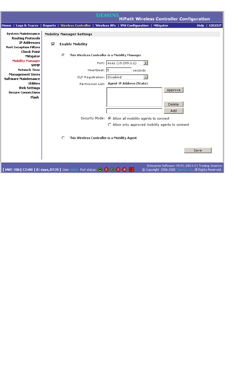
2. In the left pane, click Mobility Manager. The Mobility Manager Settings
page is displayed.
Availability, mobility, and controller functionality
hwc_controlleravailmobility.fm
Mobility manager
A31003-W1050-U100-2-7619,March 2008
262 HiPath Wireless Controller, Access Points and Convergence Software V5 R1 , C20/C2400 User Guide
3. To enable mobility for this controller, select the Enable Mobility checkbox.
The controller mobility options appear.
4. Select the This Wireless Controller is a Mobility Manager option. The
mobility manager options appear.
5. In the Port drop-down list, click the interface on the HiPath Wireless
Controller to be used for the mobility manager process. Ensure that the
selected interface is routable on the network.
6. In the Heartbeat box, type the time interval (in seconds) at which the mobility
manager sends a Heartbeat message to a mobility agent. The default is 5
seconds.
7. In the SLP Registration drop-down list, click whether to enable or disable
SLP registration.
8. In the Permission list, click the agent IP addresses you want to approve that
are in pending state, by selecting the agent and clicking Approve. New
agents are only added to the domain if they are approved.
You can also add or delete controllers that you want to be part of the mobility
domain. To add a controller, type the agent IP address in the box, and then
click Add. To delete a controller, click the controller in the list, and then click
Delete.
9. Select the Security Mode option:
hwc_controlleravailmobility.fm
Availability, mobility, and controller functionality
Mobility manager
A31003-W1050-U100-2-7619, March 2008
HiPath Wireless Controller, Access Points and Convergence Software V5 R1 , C20/C2400 User Guide 263
• Allow all mobility agents to connect – All mobility agents can connect
to the mobility manager.
• Allow only approved mobility agents to connect – Only approved
mobility agents can connect to the mobility manager.
10. To save your changes, click Save.
Note: If you set up one HiPath Wireless Controller on the network as a mobility
manager, all other HiPath Wireless Controllers must be set up as mobility agents.
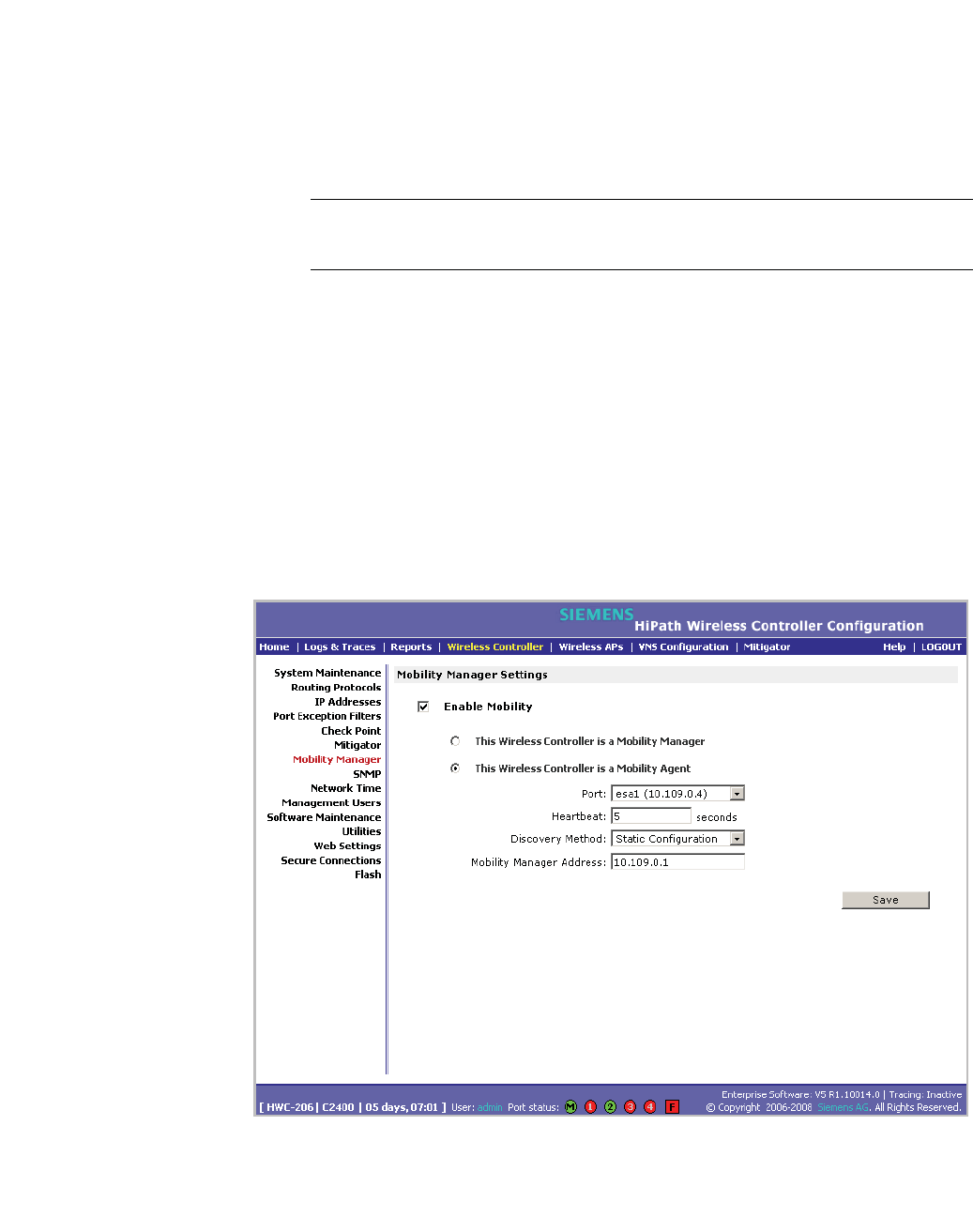
To designate a mobility agent:
1. From the main menu, click Wireless Controller Configuration. The
Wireless Controller Configuration page is displayed.
2. In the left pane, click Mobility Manager. The Mobility Manager Settings
page is displayed.
3. To enable mobility for this controller, select the Enable Mobility checkbox.
The controller mobility options are displayed,
4. Select the This Wireless Controller is a Mobility Agent option. The mobility
agent options are displayed.

Availability, mobility, and controller functionality
hwc_controlleravailmobility.fm
Defining management users
A31003-W1050-U100-2-7619,March 2008
264 HiPath Wireless Controller, Access Points and Convergence Software V5 R1 , C20/C2400 User Guide
5. From the Port drop-down list, click the port on the HiPath Wireless Controller
to be used for the mobility agent process. Ensure that the port selected is
routable on the network.
6. In the Heartbeat box, type the time interval (in seconds) to wait for a
connection establishment response before trying again. The default is 60
seconds.
7. From the Discovery Method drop-down list, click one of the following:
•SLPD – Service Location Protocol Daemon is a background process
acting as a SLP server. It provides the functionality of the Directory Agent
and Service Agent for SLP. Use SLP to support the discovery of
siemensNET service to attempt to locate the area mobility manager
controller.
• Static Configuration – Select Static Configuration if you want to enter
the IP address of the mobility manager manually. Defining a static
configuration for a mobility manager IP address bypasses SLP discovery.
8. In the Mobility Manager Address box, type the IP address for the
designated mobility manager.
9. To save your changes, click Save.
7.2.1 Displays for the mobility manager
For more information, see Section 10.1.4, “Viewing displays for the mobility
manager”, on page 300.
7.3 Defining management users
On this page you define the login user names that have access to the HiPath
Wireless Assistant, either for HiPath Controller, Access Points and Convergence
Software administrators with read/write privileges, or users with read only
privileges. For each user added, you can also define and modify a user ID and
password.
Note: When adding or modifying a management user, note the following
password character constraints:
• Allowed characters include A-Z a-z 0-9 ~!@#$%^&*()_+|-=\{}[];<>?,./
• Characters not allowed include ` ' " : and space is not valid.
hwc_controlleravailmobility.fm
Availability, mobility, and controller functionality
Defining management users
A31003-W1050-U100-2-7619, March 2008
HiPath Wireless Controller, Access Points and Convergence Software V5 R1 , C20/C2400 User Guide 265
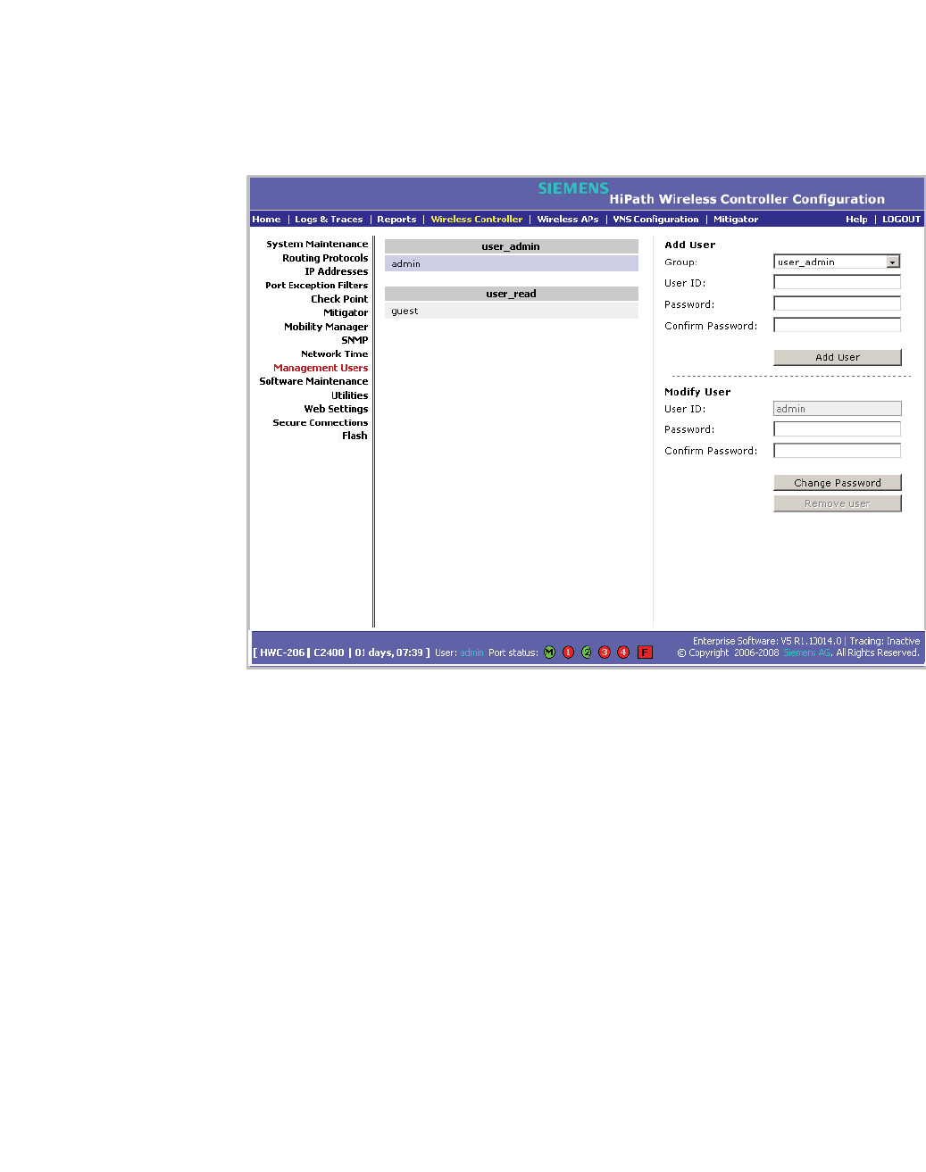
To add a HiPath Wireless Controller management user:
1. From the main menu, click Wireless Controller Configuration. The
Wireless Controller Configuration page is displayed.
2. In the left pane, click Management Users. The Management Users page is
displayed.
The user_admin list displays Admin users who have read/write privileges.
The user_read list is for users who have read only privileges.
3. From the Group drop-down list, click Admin or Read only.
4. In the User ID box, type the user ID for the new user. A User ID can only be
used once, in only one category.
5. In the Password box, type the password for the new user.
6. In the Confirm Password, retype the password.
7. Click Add User. The new user is added to the appropriate user list.
To modify a HiPath Wireless Controller management user:
1. From the main menu, click Wireless Controller Configuration. The
Wireless Controller Configuration page is displayed.
2. In the left pane, click Management Users. The Management Users page is
displayed.
3. Click the user you want to modify.

Availability, mobility, and controller functionality
hwc_controlleravailmobility.fm
Configuring network time
A31003-W1050-U100-2-7619,March 2008
266 HiPath Wireless Controller, Access Points and Convergence Software V5 R1 , C20/C2400 User Guide
4. In the Password box, type the new password for the user.
5. In the Confirm Password, retype the new password.
6. To change the password, click Change Password.
To remove a HiPath Wireless Controller management user:
1. From the main menu, click Wireless Controller Configuration. The
Wireless Controller Configuration page is displayed.
2. In the left pane, click Management Users. The Management Users page is
displayed.
3. Click the user you want to remove.
4. To remove the user, click Remove user. The user is removed from the list.
7.4 Configuring network time
You can synchronize the elements on the network to a universal clock. This
ensures accuracy in usage logs. Network time is synchronized in one of two
ways:
•using system time
•using Network Time Protocol (NTP), an Internet standard protocol that
synchronizes client workstation clocks.
Note: If the HiPath Wireless Controller is left powered-down for more than 78
hours, its capacitor dies down and is unable to keep the system clock working. In
such a case, you must synchronize the network time, using the NTP server. If the
NTP server is not reachable, you must first manually set the system to the correct
time, and then use the system time to synchronize the network time.
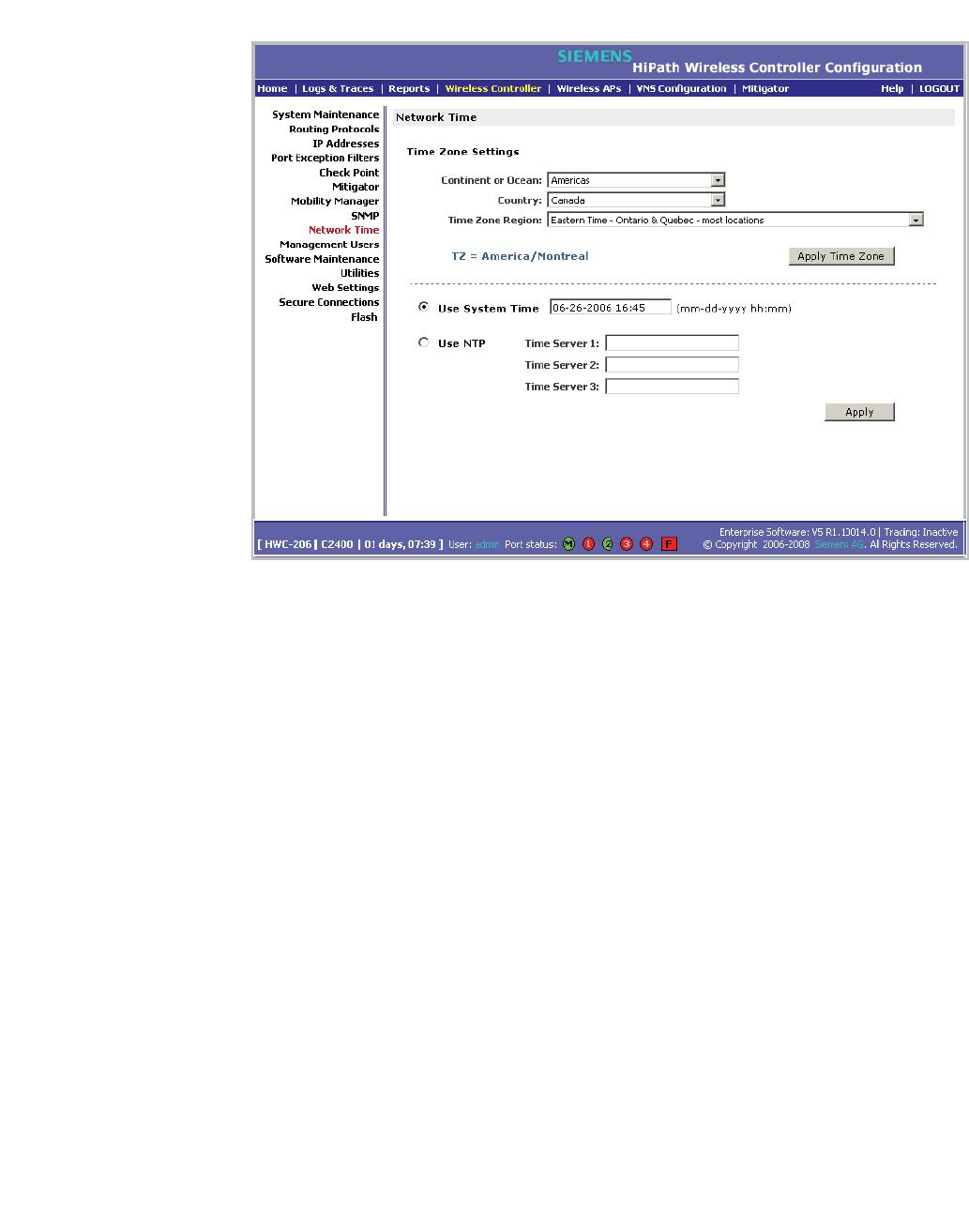
To apply time zone settings:
1. From the main menu, click Wireless Controller Configuration. The
Wireless Controller Configuration page is displayed.
2. In the left pane, click Network Time. The Network Time page is displayed.
hwc_controlleravailmobility.fm
Availability, mobility, and controller functionality
Configuring network time
A31003-W1050-U100-2-7619, March 2008
HiPath Wireless Controller, Access Points and Convergence Software V5 R1 , C20/C2400 User Guide 267
3. From the Continent or Ocean drop-down list, click the appropriate
large-scale geographic grouping for the time zone.
4. From the Country drop-down list, click the appropriate country for the time
zone. The contents of the drop-down list change based on the selection in the
Continent or Ocean drop-down list.
5. From the Time Zone Region drop-down list, click the appropriate time zone
region for the selected country.
6. To apply your changes, click Apply Time Zone.
To set system time parameters:
1. From the main menu, click Wireless Controller Configuration. The
Wireless Controller Configuration page is displayed.
2. In the left pane, click Network Time. The Network Time page is displayed.
3. To use system time, select the Use System Time radio button.
4. Type the time setting in the Use System TIme box, using the mm-dd-yyyy
hh:mm format.
5. To apply your changes, click Apply.

Availability, mobility, and controller functionality
hwc_controlleravailmobility.fm
Configuring Check Point event logging
A31003-W1050-U100-2-7619,March 2008
268 HiPath Wireless Controller, Access Points and Convergence Software V5 R1 , C20/C2400 User Guide
To set Network Time Protocol:
1. From the main menu, click Wireless Controller Configuration. The
Wireless Controller Configuration page is displayed.
2. In the left pane, click Network Time. The Network Time page is displayed.
3. To use Network Time Protocol, select the Use NTP radio option.
4. In the Use System Time box, type the time setting using the mm-dd-yyyy
hh:mm format.
5. In the Time Server 1 box, type the IP address or FQDN of a standard NTP
Time Server. You can repeat this step for the Time Server 2 and Time Server
3boxes.
6. To apply your changes, click Apply.
7.5 Configuring Check Point event logging
The HiPath Wireless Controller can forward specified event messages to an ELA
server using the OPSEC ELA protocol - Event Logging API (Application Program
Interface). On the ELA server, the event messages are tracked and analyzed, so
suspicious messages can be forwarded to a firewall application that can take
corrective action.
Check Point created the OPSEC (Open Platform for Security) alliance program
for security application and appliance vendors to enable an open industry-wide
framework for inter operability.
When ELA is enabled on the HiPath Wireless Controller, it forwards the specified
event messages from its internal event server to the designated ELA
Management Station on the enterprise network.
Note: Before you set up the HiPath Wireless Controller, you must first create
OPSEC objects for HiPath Wireless Controller in the Check Point management
software. The name and password you define must also be entered into the
Check Point Configuration page.
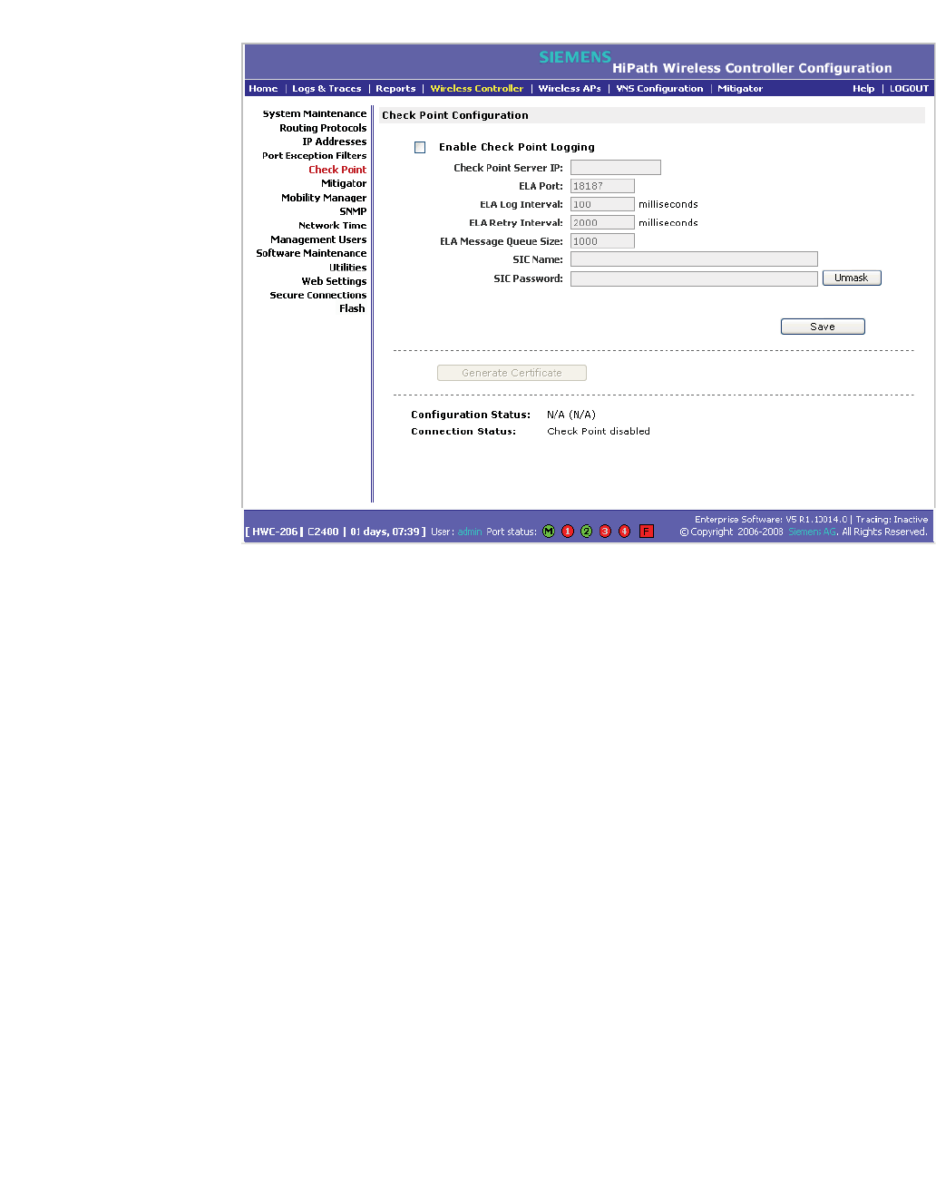
To enable and configure Check Point:
1. From the main menu, click Wireless Controller Configuration. The
Wireless Controller Configuration page is displayed.
2. In the left pane, click Check Point. The Check Point Configuration page is
displayed.
hwc_controlleravailmobility.fm
Availability, mobility, and controller functionality
Configuring Check Point event logging
A31003-W1050-U100-2-7619, March 2008
HiPath Wireless Controller, Access Points and Convergence Software V5 R1 , C20/C2400 User Guide 269
3. To enable check point logging, select the Enable Check Point Logging
checkbox.
4. Type the following information:
• Check Point Server IP – Specifies the IP address of the ELA
Management Station
•ELA Port – Specifies the port to use for ELA. The default port is 18187.
• ELA Log Interval – Specifies the amount of time (in milliseconds) you
want the system to wait before attempting to log once there is a
connection between HiPath Wireless Controller and the Check Point
gateway. The default is 100 milliseconds.
• ELA Retry Interval – Specifies the amount of time (in milliseconds) you
want the system to wait before attempting a re-connection between
HiPath Wireless Controller and the Check Point gateway. The default is
2000 milliseconds.
• ELA Message Queue Size – Specifies the number of messages the log
queue holds if the HiPath Wireless Controller and the Check Point
gateway become disconnected. The default is 1000 log entries.
•SIC Name – Specifies the Secure Internal Communication (SIC) Name,
your security-based ID.

Availability, mobility, and controller functionality
hwc_controlleravailmobility.fm
Enabling SNMP
A31003-W1050-U100-2-7619,March 2008
270 HiPath Wireless Controller, Access Points and Convergence Software V5 R1 , C20/C2400 User Guide
• SIC Password – Specifies your Secure Internal Communication (SIC)
password. You can use the Unmask button to display the password.
5. To save your changes, click Save.
6. To create the certificate to be sent to the ELA Management Station, click
Generate Certificate.
If the certificate is properly generated and the connection with the ELA
Management Station is made, the Connection Status section displays the
following message:
OPSEC Connection OK
If there is an error in generating the certificate or establishing the connection,
the Connection Status section displays the following message:
OPSEC Connection Error
7.5.1 ELA Management Station events
The events for the ELA Management Station are grouped under Siemens and are
mapped as info events and alert events. The alerts include:
•Wireless AP registration and/or authentication failed
•Authentication User Request unsuccessful
•RADIUS server rejected login (Access Rejected)
•An unknown AP has attempted to connect. AP authentication failure.
•A connection request failed to authenticate with the CM messaging server.
This may indicate port-scanning of the HiPath Wireless Controller, or a back-
door access attempt.
•Unauthorized client attempting to connect
7.6 Enabling SNMP
The HiPath Wireless Controller, Access Points and Convergence Software
system supports Simple Network Management Protocol (SNMP), Version 1 and
2c. SNMP, a set of protocols for managing complex networks, is used to retrieve
HiPath Wireless Controller statistics and configuration information.

hwc_controlleravailmobility.fm
Availability, mobility, and controller functionality
Enabling SNMP
A31003-W1050-U100-2-7619, March 2008
HiPath Wireless Controller, Access Points and Convergence Software V5 R1 , C20/C2400 User Guide 271
SNMP sends messages, called protocol data units (PDUs), to different parts of a
network. Devices on the network that are SNMP-compliant, called agents, store
data about themselves in Management Information Bases (MIBs) and return this
data to the SNMP requesters.
Note: In this current release (V5 R1), the SNMP protocol does not support the
Wireless 802.11n AP since some of the Wireless 802.11n AP properties are not
accurately reported.
7.6.1 MIB support
The HiPath Wireless Controller, Access Points and Convergence Software
system accepts SNMP Get commands and generates Trap messages. Support
is provided for the retrieval information from the router MIB-II (SNMP_GET) as
well as SNMP traps. The supported MIBs include:
•SNMPv2-MIB
•IF-MIB
•IEEE802dot11-MIB
•RFC1213-MIB
Note: The HiPath Wireless Controller is not fully compliant with MIB II. For
example, esa/IXP ports only provide interface statistics.
The Siemens Enterprise MIB includes:
•HIPATH-WIRELESS-HWC-MIB
•HIPATH-WIRELESS-PRODUCTS-MIB
•HIPATH-WIRELESS-SMI.my
•HIPATH-WIRELESS-DOT11-EXTNS-MIB
•HIPATH-WIRELESS-BRANCH-OFFICE-MIB
The MIB is provided for compilation into an external NMS. No support has been
provided for automatic device discovery by an external NMS.
The HiPath Wireless Controller is the only point of SNMP access for the entire
system. In effect, the HiPath Wireless Controller proxies sets, gets, and alarms
from the associated Wireless APs.
Availability, mobility, and controller functionality
hwc_controlleravailmobility.fm
Enabling SNMP
A31003-W1050-U100-2-7619,March 2008
272 HiPath Wireless Controller, Access Points and Convergence Software V5 R1 , C20/C2400 User Guide
7.6.2 Enabling SNMP on the HiPath Wireless
Controller
You can enable SNMP on the HiPath Wireless Controller to retrieve statistics and
configuration information.
To enable SNMP Parameters:
1. From the main menu, click Wireless Controller Configuration. The
Wireless Controller Configuration page is displayed.
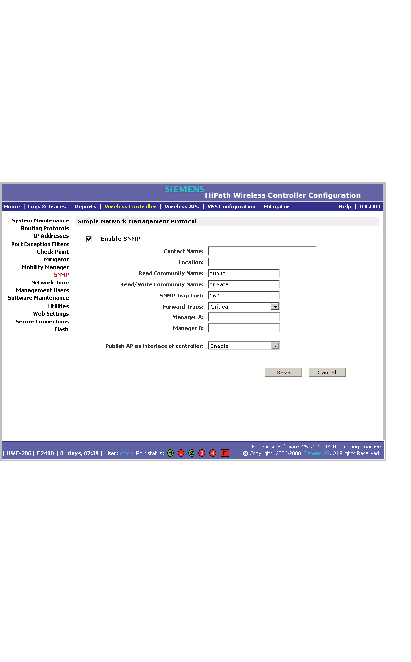
2. In the left pane, click SNMP. The Simple Network Management Protocol
page is displayed.
3. Type the following:
• Contact Name – Specifies the name of SNMP administrator.
• Location – Specifies the location of the SNMP administration machine.
• Read Community Name – Specifies the community name for users with
read privileges.
• Read/Write Community Name – Specifies the community name for
users with read and write privileges.
• SNMP Trap Port – Specifies the destination port for SNMP traps. The
industry standard is 162. If left blank, no traps are generated.

hwc_controlleravailmobility.fm
Availability, mobility, and controller functionality
Using controller utilities
A31003-W1050-U100-2-7619, March 2008
HiPath Wireless Controller, Access Points and Convergence Software V5 R1 , C20/C2400 User Guide 273
•Forward Traps – Specifies the security level of the traps to be forwarded.
From the drop-down list, click Informational,Minor,Major, or Critical.
• Manager A – Specifies the IP address of the specific machine on the
network where the SNMP traps are monitored.
• Manager B – Specifies the IP address of a second machine on the
network where the SNMP traps are monitored, if Manager A is not
available.
Note: For security purposes, it is recommended that you immediately
change the Read Community Name (public) and the Read/Write
Community Name (private) to names that are less obvious and more
secure.
4. In the Publish AP as interface of controller drop-down list, click whether to
enable or disable publishing the Wireless AP and their interfaces as
interfaces of the HiPath Wireless Controller. By default this option is enabled.
When this option is enabled, all Wireless APs and their interfaces are
published as interfaces of the HiPath Wireless Controller when you retrieve
topology statistics and configuration information using the SNMP protocol.
Topology statistics and configuration information on Wireless APs are
retrievable using both proprietary and standard MIB. The Publish AP as
interface of controller option only affects information retrieved through
standard MIB, i.e. IF-MIB, RFC1213. All information that is retrieved through
proprietary MIB is not affected. If the Publish AP as interface of controller
option is disabled, the Wireless APs' interfaces are not considered interfaces
of the HiPath Wireless Controller.
For example, if the Publish AP as interface of controller option is disabled,
querying the ifTable would return information on the HiPath Wireless
Controller physical interfaces, plus all VNSs that are configured on that
controller. If enabled, querying the same table would return the above
information, in addition to information on each Wireless APs’ interfaces.
5. To save your changes, click Save.
7.7 Using controller utilities
You can use HiPath Wireless Controller utilities to test a connection to the target
IP address or to record the route through the Internet between your computer and
the target IP address.
Availability, mobility, and controller functionality
hwc_controlleravailmobility.fm
Using controller utilities
A31003-W1050-U100-2-7619,March 2008
274 HiPath Wireless Controller, Access Points and Convergence Software V5 R1 , C20/C2400 User Guide
To test or record IP address connections:
1. From the main menu, click Wireless Controller Configuration. The
Wireless Controller Configuration page is displayed.
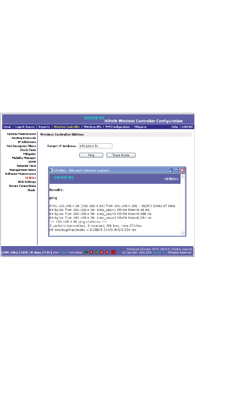
2. In the left pane, click Utilities. The Wireless Controller Utilities page is
displayed.
3. In the Target IP Address box, type the IP address of the destination
computer.
4. To test a connection to the target IP address, click Ping. A pop-up window is
displayed with the ping results.
The following is an example of ping results.
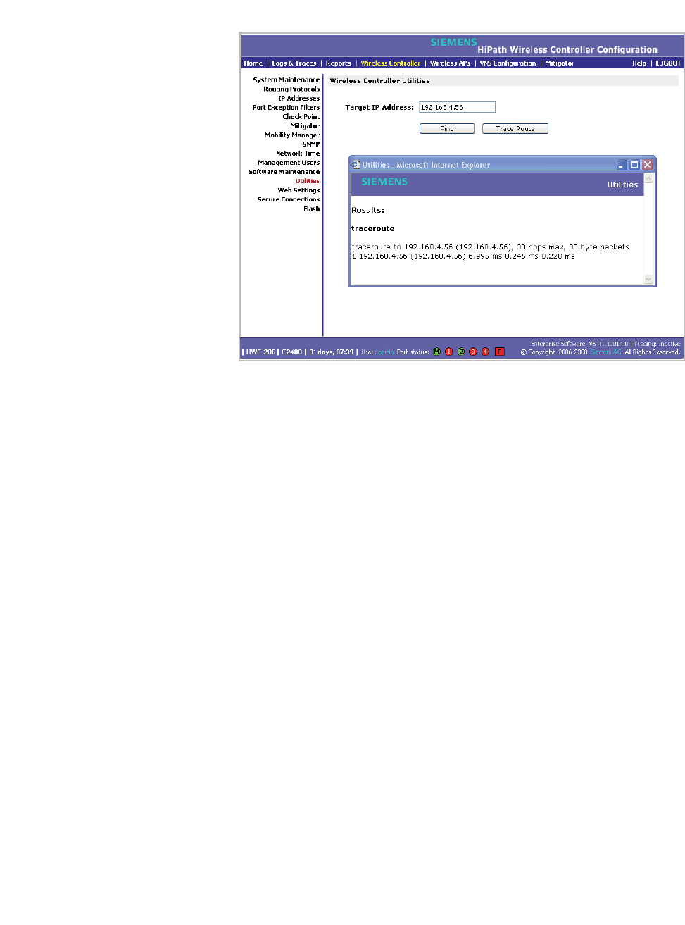
5. To record the route through the Internet between your computer and the
target IP address, click Trace Route.
The following is an example of trace results.
hwc_controlleravailmobility.fm
Availability, mobility, and controller functionality
Configuring Web session timeouts
A31003-W1050-U100-2-7619, March 2008
HiPath Wireless Controller, Access Points and Convergence Software V5 R1 , C20/C2400 User Guide 275
7.8 Configuring Web session timeouts
You can configure the time period to allow Web sessions to remain inactive before
timing out.
To configure Web session timeouts:
1. From the main menu, click Wireless Controller Configuration. The
Wireless Controller Configuration page is displayed.
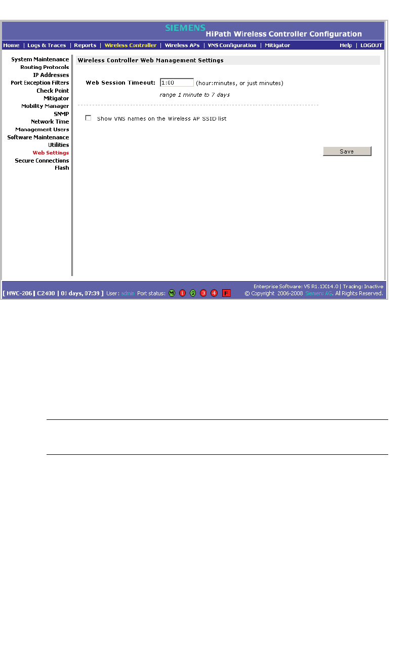
2. In the left pane, click Web Settings The Wireless Controller Web
Management Settings page is displayed.
Availability, mobility, and controller functionality
hwc_controlleravailmobility.fm
Configuring Web session timeouts
A31003-W1050-U100-2-7619,March 2008
276 HiPath Wireless Controller, Access Points and Convergence Software V5 R1 , C20/C2400 User Guide
3. In the Web Session Timeout box, type the time period to allow the Web
session to remain inactive before it times out. This can be entered as
hour:minutes, or as minutes. The range is 1 minute to 168 hours.
4. Select the Show VNS names on the Wireless AP SSID list checkbox to
allow the names of the VNSs to appear in the SSID list for Wireless APs.
5. To save your settings, click Save.
Note: Pages that auto-refresh will time-out, unless a manual action takes
place prior to the end of the timeout period.

hwc_3rdpartyaps.fm
A31003-W1050-U100-2-7619, March 2008
HiPath Wireless Controller, Access Points and Convergence Software V5 R1 , C20/C2400 User Guide 277
Working with third-party APs
8 Working with third-party APs
You can set up the HiPath Wireless Controller to handle wireless device traffic
from third-party access points, providing the same policy and network access
control. This process requires the following steps:
•Step 1 – Define a data port as a third party AP port:
•Step 2 – Define a VNS for the third-party AP port:
•Step 3 – Define authentication by Captive Portal and RAD policy for the third-
party AP VNS:
•Step 4 – Define filtering rules for the third-party APs:
Attention: The HiPath Wireless Outdoor AP is not a third party AP. The HiPath
Wireless Outdoor AP belongs to the HiPath product family.
To set up third-party APs:
Step 1 – Define a data port as a third party AP port:
1. From the main menu, click Wireless Controller Configuration. The
Wireless Controller Configuration page is displayed.
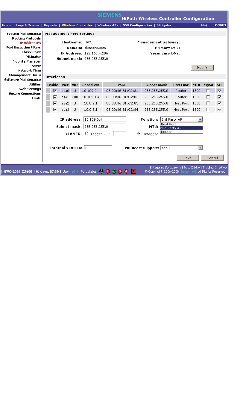
2. From the left pane, click IP Address. The Management Port Settings and
Interfaces page is displayed.
Working with third-party APs
hwc_3rdpartyaps.fm
A31003-W1050-U100-2-7619,March 2008
278 HiPath Wireless Controller, Access Points and Convergence Software V5 R1 , C20/C2400 User Guide
3. Click the port, and in the Function box, click 3rd-party AP from the
drop-down list. Make sure that Management Traffic and SLP are disabled for
this port.
4. Connect the third-party access point to this port, via a switch.
Step 2 – Define a VNS for the third-party AP port:
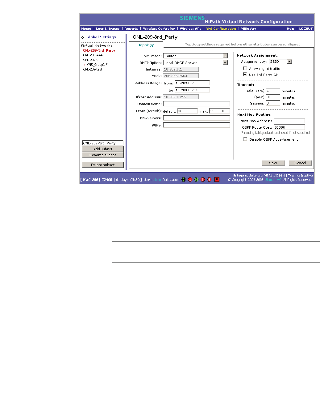
1. From the main menu, click Virtual Network Configuration. The Virtual
Network Configuration page is displayed.
2. In the left pane, type a name that will identify the new VNS in the Add subnet
box, and then click Add subnet. The name is displayed in the Virtual
Networks list. The Topology tab is displayed.
hwc_3rdpartyaps.fm
Working with third-party APs
A31003-W1050-U100-2-7619, March 2008
HiPath Wireless Controller, Access Points and Convergence Software V5 R1 , C20/C2400 User Guide 279
3. In the Assignment by drop-down list, click SSID.
4. To define a VNS for a third-party AP, select the Use 3rd Party AP checkbox.
5. Continue configuring your VNS, as described in Section 6.3.1, “Configuring
topology for a VNS for Captive Portal”, on page 165.
Note: Bridge Traffic at AP and MAC-based authentication are not available
for third-party VNSs.
Step 3 – Define authentication by Captive Portal and RAD policy for the
third-party AP VNS:
1. Click the Auth & Acct tab.
2. In the Authentication Configuration page, click Configure Captive Portal
Settings.
3. In the Captive Portal Settings page, define the Captive Portal configuration.
4. Click the RAD Policy tab.
5. Define the the filter IDs to match those in RADIUS server.

Working with third-party APs
hwc_3rdpartyaps.fm
A31003-W1050-U100-2-7619,March 2008
280 HiPath Wireless Controller, Access Points and Convergence Software V5 R1 , C20/C2400 User Guide
Step 4 – Define filtering rules for the third-party APs:
1. Because the third-party APs are mapped to a physical port, you must define
the Exception filters on the physical port, using the Port Exception Filters
page. For more information, see Section 6.9, “Configuring filtering rules for a
VNS”, on page 194.
2. Define filtering rules that allow access to other services and protocols on the
network such as HTTP, FTP, Telnet, SNMP.
In addition, modify the following functions on the third-party access point:
•Disable the access point's DHCP server, so that the IP address assignment
for any wireless device on the AP is from the DHCP server at the HiPath
Wireless Controller with VNS information.
•Disable the third-party access point's layer-3 IP routing capability and set the
access point to work as a layer-2 bridge.
Here are the differences between third-party access points and Wireless APs on
the HiPath Wireless Controller, Access Points and Convergence Software
system:
•A third-party access point exchanges data with the HiPath Wireless
Controller's data port using standard IP over Ethernet protocol. The third-
party access points do not support the tunnelling protocol for encapsulation.
•For third-party access points, the VNS is mapped to the physical data port
and this is the default gateway for mobile units supported by the third-party
access points.
•A HiPath Wireless Controller cannot directly control or manage the
configuration of a third-party access point.
•Third-party access points are required to broadcast an SSID unique to their
segment. This SSID cannot be used by any other VNS.
•Roaming from third-party access points to Wireless APs and vice versa is not
supported.

hwc_mitigator.fm
A31003-W1050-U100-2-7619, March 2008
HiPath Wireless Controller, Access Points and Convergence Software V5 R1 , C20/C2400 User Guide 281
Working with the Mitigator
Mitigator overview
9 Working with the Mitigator
This chapter describes Mitigator concepts, including:
•Mitigator overview
•Enabling the Analysis and data collector engines
•Running Mitigator scans
•Analysis engine overview
•Working with Mitigator scan results
•Working with friendly APs
•Maintaining the Mitigator list of APs
•Viewing the Scanner Status report
9.1 Mitigator overview
The Mitigator is a mechanism that assists in the detection of rogue APs. Mitigator
functionality does the following:
Wireless AP:
•Runs a radio frequency (RF) scanning task.
•Alternating between scan functions, providing its regular service to the
wireless devices on the network.
Note: If a Wireless AP is part of a WDS link you cannot configure it to act as a
scanner in Mitigator.
HiPath Wireless Controller:
•Runs a data collector application that receives and manages the RF scan
messages sent by the Wireless AP. RF data collector data includes lists of all
connected Wireless APs, third-party APs, and the RF scan information that
has been collected from the Wireless APs selected to perform the scan.
Working with the Mitigator
hwc_mitigator.fm
Enabling the Analysis and data collector engines
A31003-W1050-U100-2-7619,March 2008
282 HiPath Wireless Controller, Access Points and Convergence Software V5 R1 , C20/C2400 User Guide
•Runs an Analysis Engine that processes the scan data from the data collector
through algorithms that make decisions about whether any of the detected
APs or clients are rogue APs or are running in an unsecure environment (for
example, ad-hoc mode).
Note: In a network with more than one HiPath Wireless Controller, it is not
necessary for the data collector to be running on the same controller as the
Analysis Engine. One controller can be a dedicated Analysis Engine while the
other controllers run data collector functionality. No more than one Analysis
Engine can be running at a time. You must ensure that the controllers are all
routable.
9.2 Enabling the Analysis and data collector engines
Before using the Mitigator, you must enable and define the Analysis and data
collector engines.
To enable the Analysis engine:
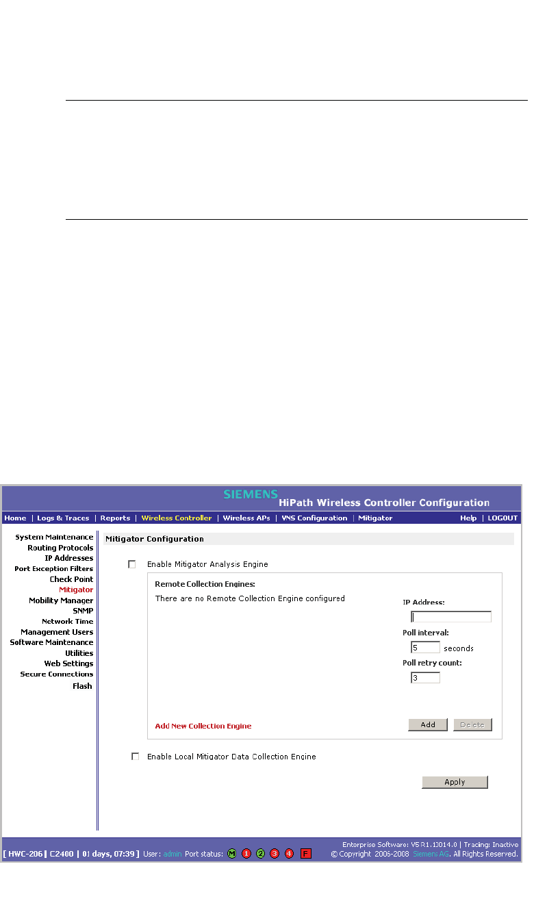
1. From the main menu, click Wireless Controller Configuration. The
Wireless Controller Configuration page is displayed.
2. In the left pane, click Mitigator. The Mitigator Configuration page is
displayed.

hwc_mitigator.fm
Working with the Mitigator
Running Mitigator scans
A31003-W1050-U100-2-7619, March 2008
HiPath Wireless Controller, Access Points and Convergence Software V5 R1 , C20/C2400 User Guide 283
3. To enable the Mitigator Analysis Engine, select the Enable Mitigator
Analysis Engine checkbox.
4. To enable the Mitigator Data Collection Engine on this HiPath Wireless
Controller, select the Enable Local Mitigator Data Collection Engine
checkbox.
5. To identify the remote RF Data Collector Engine that the Analysis Engine will
poll for data, type the IP address of the HiPath Wireless Controller on which
the remote Data Collector resides in the IP Address box.
Note: Currently, the HiPath Wireless Controller C20 does not support the
Remote Collection Engines functionality of the HiPath Wireless Controller,
Access Points and Convergence Software solution. The Remote Collection
Engines functionality is only available for the HiPath Wireless Controller
C2400.
6. For the data collection engine:
•In the Poll interval box, type (in seconds) the interval that the Analysis
Engine will poll the RF Data Collector to maintain connection status. The
default is 30 seconds.
•In the Poll retry count box, type the number of times the Analysis Engine
will attempt to poll the RF Data Collector to maintain connection status,
before it stops sending requests. The default is 2 attempts.
7. Click Add. The IP address of the Data Collection Engine, with its Poll Interval
and Poll Retry parameters is displayed in the list.
Note: For each remote RF Data Collection Engine defined here, you must:
• Enable it by selecting the Enable Mitigator Analysis Engine checkbox on
the remote HiPath Wireless Controller
• Ensure that the controllers are routable by whatever means you use (for
example, static routes, or OSPF).
8. To add a new collection engine, click Add Collection Engine.
9. Repeat steps 4 to 7.
10. To save your changes, click Apply.
9.3 Running Mitigator scans
The Mitigator feature allows you to view the following:
Working with the Mitigator
hwc_mitigator.fm
Running Mitigator scans
A31003-W1050-U100-2-7619,March 2008
284 HiPath Wireless Controller, Access Points and Convergence Software V5 R1 , C20/C2400 User Guide
•Scan Groups
•Friendly APs
•AP Maintenance
Note: A scan will not run on an inactive AP, even though it is displayed as part of
the Scan Group. If it becomes active, it will be sent a scan request during the next
periodic scan.
Note: The HiPath Wireless 802.11n APs can not be added to the Scan Group
because they are not equipped to carry out scanning.
To run the Mitigator scan task mechanism:
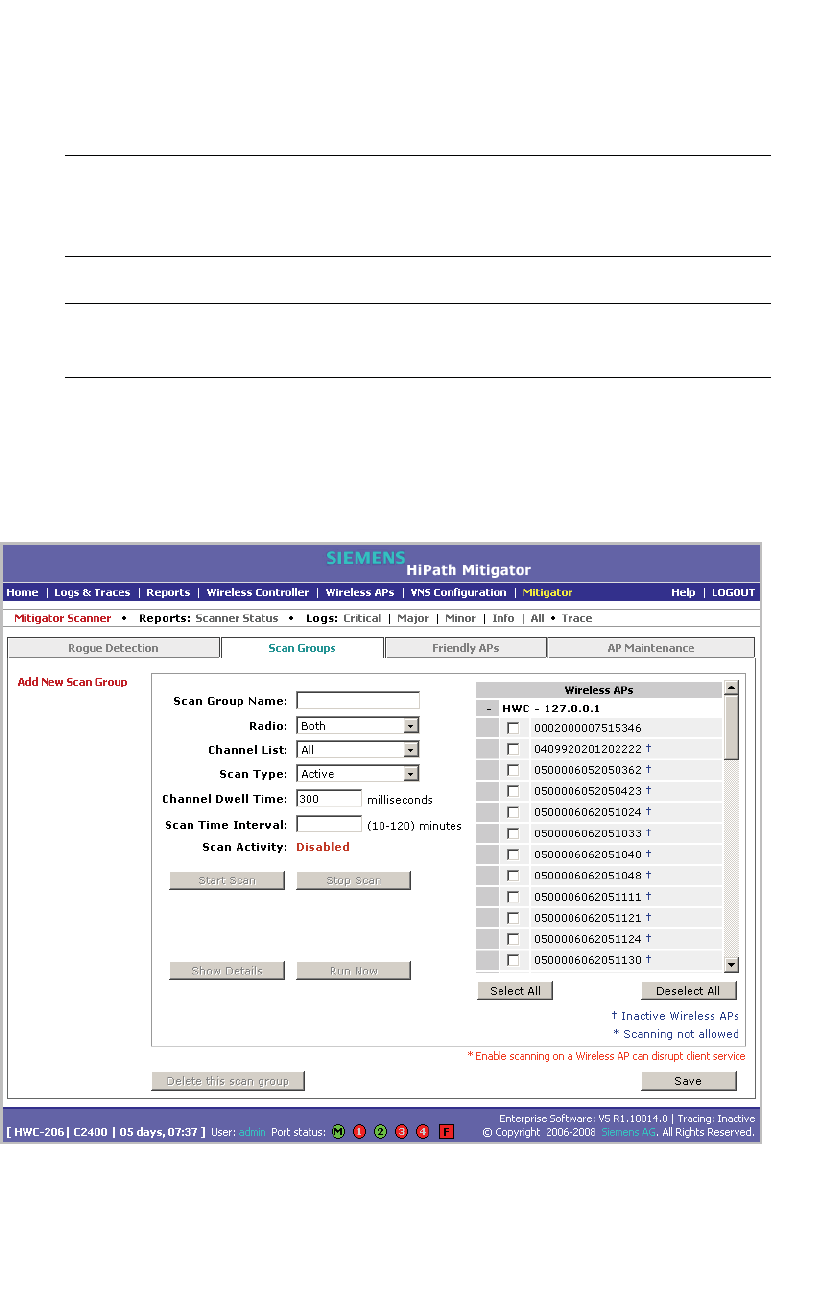
1. From the main menu, click Mitigator. The Mitigator page is displayed.
2. Click the Scan Groups tab.
3. In the Scan Group Name box, type a unique name for this scan group.

hwc_mitigator.fm
Working with the Mitigator
Running Mitigator scans
A31003-W1050-U100-2-7619, March 2008
HiPath Wireless Controller, Access Points and Convergence Software V5 R1 , C20/C2400 User Guide 285
4. In the Wireless APs list, select the checkbox corresponding to the Wireless
APs you want included in the new scan group, which will perform the scan
function.
Note: A Wireless AP can participate in only one Scan Group at a time. It is
recommended that the Scan Groups represent geographical groupings of
Wireless APs.
5. In the Radio drop-down list, click one of the following:
•Both – The a and b/g radios both perform the scan function.
•a – Only the a radio performs the scan function.
•b/g – Only the b/g radio performs the scan function.
6. In the Channel List drop-down list, click one of the following:
•All – Scanning is performed on all channels.
• Current – Scanning is performed on only the current channel.
7. In the Scan Type drop-down list, click one of the following:
•Active – The Wireless AP sends out ProbeRequests and waits for
ProbeResponse messages from any access points.
• Passive – The Wireless AP listens for 802.11 beacons.
8. In the Channel Dwell Time box, type the time (in milliseconds) for the
scanner to wait for a response from either 802.11 beacons in passive
scanning, or ProbeResponse in active scanning.
9. In the Scan Time Interval box, type the time (in minutes) to define the
frequency at which a Wireless AP within the Scan Group will initiate a scan of
the RF space. The range is from one minute to 120 minutes.
10. To initiate a scan using the periodic scanning parameters defined above, click
Start Scan.
11. To initiate an immediate scan that will run only once, click Run Now.
Note: If necessary, you can stop a scan by clicking Stop Scan.
A scan must be stopped before modifying any parameters of the Scan Group,
or before adding or removing a Wireless AP from a Scan Group.
12. The Scan Activity box displays the current state of the scan engine.
13. To view a pop-up report showing the timeline of scan activity and scan results,
click Show Details.
14. To save your changes, click Save.

Working with the Mitigator
hwc_mitigator.fm
Analysis engine overview
A31003-W1050-U100-2-7619,March 2008
286 HiPath Wireless Controller, Access Points and Convergence Software V5 R1 , C20/C2400 User Guide
9.4 Analysis engine overview
The Analysis engine relies on a database of known devices on the Controller,
Access Points and Convergence Software system. The Analysis engine
compares the data from the RF Data Collector with the database of known
devices.
This database includes the following:
• Wireless APs – Registered with any HiPath Wireless Controller with its RF
Data Collector enabled and associated with the Analysis Engine on this
HiPath Wireless Controller.
• Third-party APs – Defined and assigned to a VNS.
• Friendly APs – A list created in the Mitigator user interface as potential rogue
access points are designated by the administrator as Friendly.
• Wireless devices – Registered with any HiPath Wireless Controller that has
its RF Data Collector enabled and has been associated with the Analysis
Engine on this HiPath Wireless Controller.
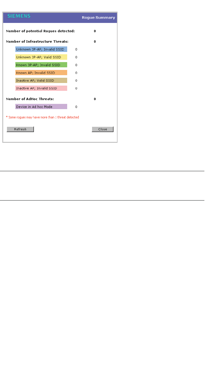
The Analysis Engine looks for access points with one or more of the following
conditions:
• Unknown MAC address and unknown SSID (critical alarm)
• Unknown MAC, with a valid SSID - a known SSID is being broadcast by the
unknown access point (critical alarm)
• Known MAC, with an unknown SSID - a rogue may be spoofing a MAC
address (critical alarm)
• Inactive Wireless AP with valid SSID (critical alarm)
• Inactive Wireless AP with unknown SSID (critical alarm)
• Known Wireless AP with an unknown SSID (major alarm)
• In ad-hoc mode (major alarm)
Note: In the current release, there is no capability to initiate a DoS attack on
the detected rogue access point. Containment of a detected rogue requires
an inspection of the geographical location of its Scan Group area, where its
RF activity has been found.
hwc_mitigator.fm
Working with the Mitigator
Working with Mitigator scan results
A31003-W1050-U100-2-7619, March 2008
HiPath Wireless Controller, Access Points and Convergence Software V5 R1 , C20/C2400 User Guide 287
9.5 Working with Mitigator scan results
When viewing the Mitigator scan results, you can delete individual or all of the
access points from the scan results. You can also add access points from the
scan results to the Friendly AP list.
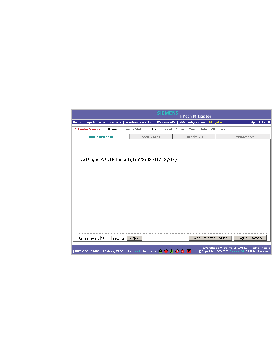
To view Mitigator scan results:
1. From the main menu, click Mitigator. The Mitigator page is displayed.
2. Click the Rogue Detection tab.
3. To modify the page’s refresh rate, type a time (in seconds) in the Refresh
every __ seconds box.
4. Click Apply. The new refresh rate is applied.
5. To view the Rogue Summary report, click Rogue Summary. The Rogue
Summary report is displayed in a pop-up window.
Working with the Mitigator
hwc_mitigator.fm
Working with Mitigator scan results
A31003-W1050-U100-2-7619,March 2008
288 HiPath Wireless Controller, Access Points and Convergence Software V5 R1 , C20/C2400 User Guide
6. To clear all detected rogue devices from the list, click Clear Detected
Rogues.
Note: To avoid the Mitigator's database becoming too large, it is recommended
that you either delete Rogue APs or add them to the Friendly APs list, rather than
leaving them in the Rogue list.
To add an AP from the Mitigator scan results to the list of friendly APs:
1. From the main menu, click Mitigator. The Mitigator page is displayed.
2. Click the Rogue Detection tab.
3. To add a Wireless AP to the Friendly APs list, click Add to Friendly List. The
AP is removed from this list and is displayed in the Friendly AP Definitions
section of the Friendly AP’s tab.
To delete an AP from the Mitigator scan results:
1. From the main menu, click Mitigator. The Mitigator page is displayed.
2. Click the Rogue Detection tab.
3. To delete a specific AP from the Mitigator scan results, click the
corresponding Delete button. The AP is removed from the list.
4. To clear all rogue access points from the Mitigator scan results, click Clear
Detected Rogues. All APs are removed from the list.
hwc_mitigator.fm
Working with the Mitigator
Working with friendly APs
A31003-W1050-U100-2-7619, March 2008
HiPath Wireless Controller, Access Points and Convergence Software V5 R1 , C20/C2400 User Guide 289
9.6 Working with friendly APs
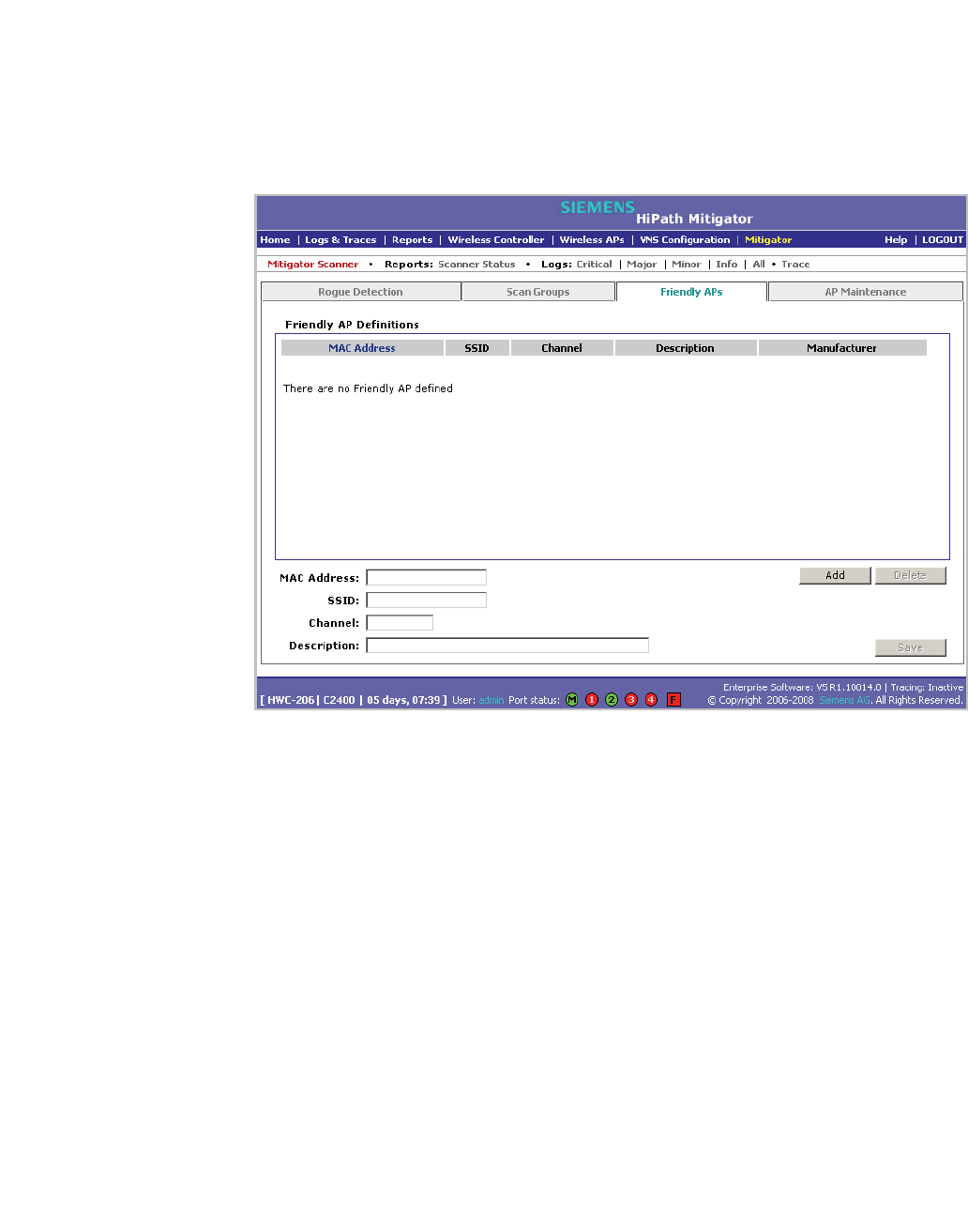
To view the friendly APs:
1. From the main menu, click Mitigator. The Mitigator page is displayed.
2. Click the Friendly APs tab.
To add friendly APs manually:
1. From the main menu, click Mitigator. The Mitigator page is displayed.
2. Click the Friendly APs tab.
3. To add friendly access points manually to the Friendly AP Definitions list,
type the following:
• MAC Address – Specifies the MAC address for the friendly AP
• SSID – Specifies the SSID for the friendly AP
• Channel – Specifies the current operating channel for the friendly AP
• Description – Specifies a brief description for the friendly AP
4. Click Add. The new access point is displayed in the list above.

Working with the Mitigator
hwc_mitigator.fm
Maintaining the Mitigator list of APs
A31003-W1050-U100-2-7619,March 2008
290 HiPath Wireless Controller, Access Points and Convergence Software V5 R1 , C20/C2400 User Guide
To delete a friendly AP:
1. From the main menu, click Mitigator. The Mitigator page is displayed.
2. Click the Friendly APs tab.
3. In the Friendly AP Definitions list, click the access point you want to delete.
4. Click Delete. The selected access point is removed from the Friendly AP
Definitions list.
5. To save your changes, click Save.
To modify a friendly AP:
1. From the main menu, click Mitigator. The Mitigator page is displayed.
2. Click the Friendly APs tab.
3. In the Friendly AP Definitions list, click the access point you want to modify.
4. Modify the access point by making the appropriate changes.
5. To save your changes, click Save.
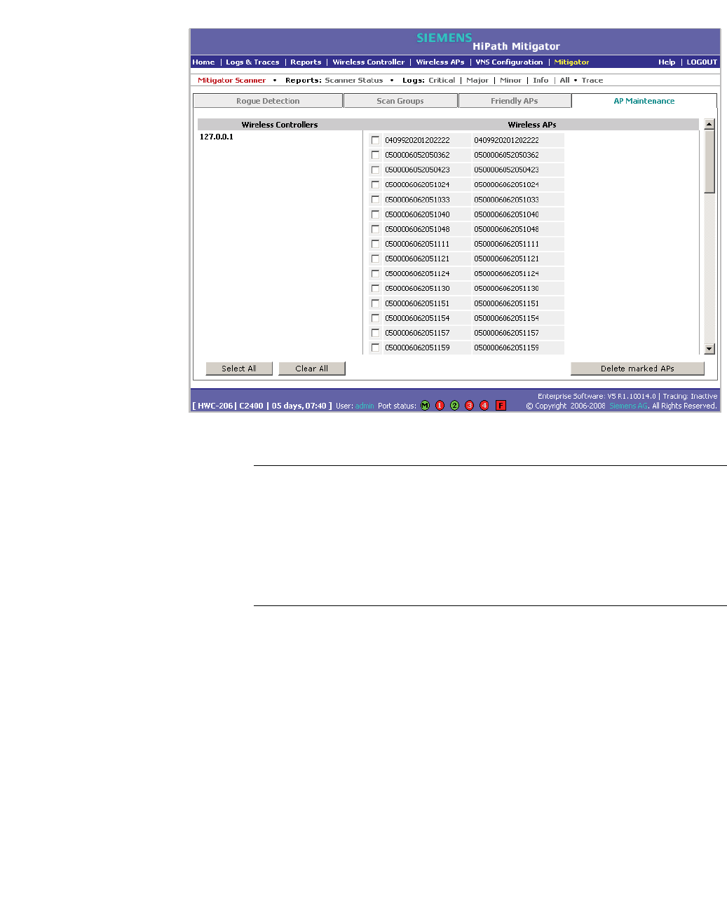
9.7 Maintaining the Mitigator list of APs
To maintain the Wireless APs:
1. From the main menu, click Mitigator. The Mitigator page is displayed.
2. Click the AP Maintenance tab. Inactive APs and known third-party APs are
displayed.
3. Select the applicable APs.
hwc_mitigator.fm
Working with the Mitigator
Maintaining the Mitigator list of APs
A31003-W1050-U100-2-7619, March 2008
HiPath Wireless Controller, Access Points and Convergence Software V5 R1 , C20/C2400 User Guide 291
4. To delete the selected APs, click Delete marked APs.
Note: The selected APs are deleted from the Mitigator database, not from the
HiPath Wireless Controller database. You can delete the APs from the HiPath
Wireless Controller database after you delete them from the Wireless AP
Configuration Access Approval page of the corresponding RF Data
Collector Engine. You can also delete the selected third-party APs if they are
removed from the corresponding VNS in the RF Collector Engine, or if that
VNS has been deleted from the VNS list.
Working with the Mitigator
hwc_mitigator.fm
Viewing the Scanner Status report
A31003-W1050-U100-2-7619,March 2008
292 HiPath Wireless Controller, Access Points and Convergence Software V5 R1 , C20/C2400 User Guide
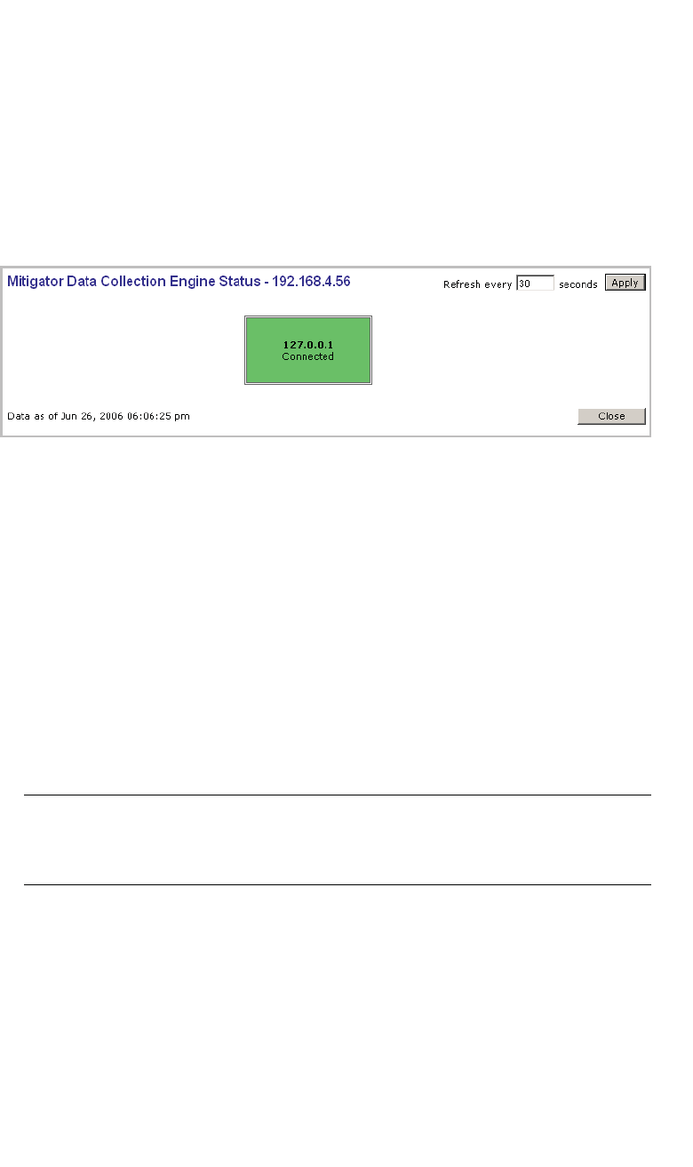
9.8 Viewing the Scanner Status report
When the Mitigator is enabled, you can view a report on the connection status of
the RF Data Collector Engines with the Analysis Engine.
To view the Mitigator scanner engine status display:
1. From the main menu, click Mitigator. The Mitigator page is displayed.
2. Click the Reports: Scanner Status. The Scanner Status report is displayed,
as shown in the example below.
The boxes display the IP address of the Data Collector engine. The status of the
Data Collector engine is indicated by one of the following colors:
•Green – The Analysis Engine has connection with the Data Collector on that
HiPath Wireless Controller.
•Yellow – The Analysis Engine has connected to the communication system
of the other controller, but has not synchronized with the Data Collector.
Ensure that the Data Collector is running on the remote controller.
•Red – The Analysis Engine is aware of the Data Collector and attempting
connection.
If no box is displayed, the Analysis Engine is not attempting to connect with that
Data Collector Engine.
Note: If the box is displayed red and remains red, ensure your IP address is
correctly set up to point to an active controller. If the box remains yellow, ensure
the Data Collector is running on the remote controller.

hwc_reports.fm
A31003-W1050-U100-2-7619, March 2008
HiPath Wireless Controller, Access Points and Convergence Software V5 R1 , C20/C2400 User Guide 293
Working with reports and displays
Viewing the displays
10 Working with reports and displays
This chapter describes the various reports and displays available in the HiPath
Wireless Controller, Access Points and Convergence Software system.
10.1 Viewing the displays
The following displays are available in the HiPath Wireless Controller, Access
Points and Convergence Software system:
•Active Wireless APs
•Active Clients by Wireless AP
•Active Clients by VNS
•Port & VNS Filter Statistics
•VNS Interface Statistics
•Wireless Controller Port Statistics
•Wireless AP Availability
•Dynamic Authorization Statistics
•Wired Ethernet Statistics by Wireless AP
•Wireless Statistics by Wireless AP
•WDS VNS Wireless AP Statistics
•System Information
•Manufacturing Information
•Client Location in Mobility Zone
•Mobility Tunnel Matrix
Note: The Client Location in Mobility Zone and Mobility Tunnel Matrix
displays only appear if the mobility manager function has been enabled for the
controller.
Working with reports and displays
hwc_reports.fm
Viewing the displays
A31003-W1050-U100-2-7619,March 2008
294 HiPath Wireless Controller, Access Points and Convergence Software V5 R1 , C20/C2400 User Guide
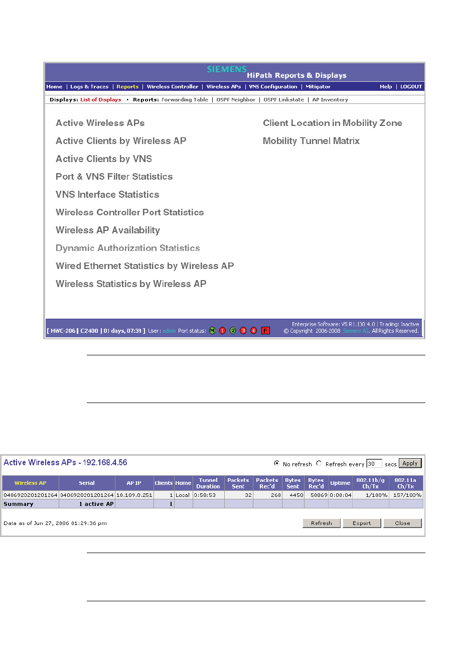
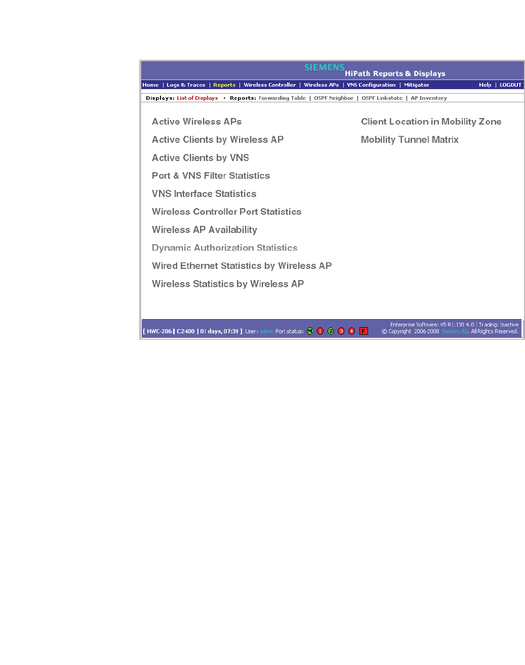
To view reports and displays:
1. From the main menu, click Reports & Displays. The HiPath Reports &
Displays page is displayed.
Note: The Client Location in Mobility Zone and Mobility Tunnel Matrix
displays only appear if the mobility manager function has been enabled for
the controller.
2. In the List of Displays, click the display you want to view (some examples
will follow):
Note: Statistics are expressed in relation to the AP. Therefore, Packets Sent
means the AP has sent that data to a client and Packets Rec’d means the
AP has received packets from a client.
hwc_reports.fm
Working with reports and displays
Viewing the displays
A31003-W1050-U100-2-7619, March 2008
HiPath Wireless Controller, Access Points and Convergence Software V5 R1 , C20/C2400 User Guide 295
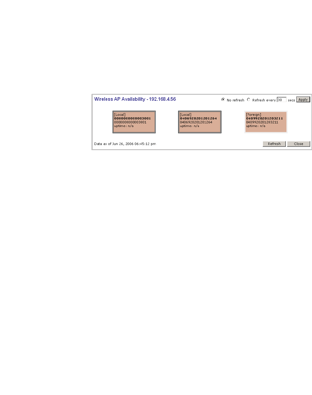
10.1.1 Viewing the Wireless AP availability display
This display reports the active connection state of a Wireless AP (availability to
the HiPath Wireless Controller for service). Depending on the state of the
Wireless AP, the following is displayed:
Green – Wireless AP is configured on the HiPath Wireless Controller and is
presently connected.
Red – Wireless AP is configured on the HiPath Wireless Controller but is
presently not connected (not available to service this HiPath Wireless Controller).
In normal operations, when the HiPath Wireless Controller Availability feature is
enabled, the local Wireless APs are green, and the foreign Wireless APs are red.
If the other HiPath Wireless Controller fails, and the foreign Wireless APs connect
to the current HiPath Wireless Controller, the display will show all Wireless APs
as green. If the Wireless APs are not connected they show up as red.
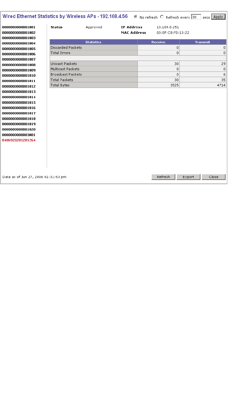
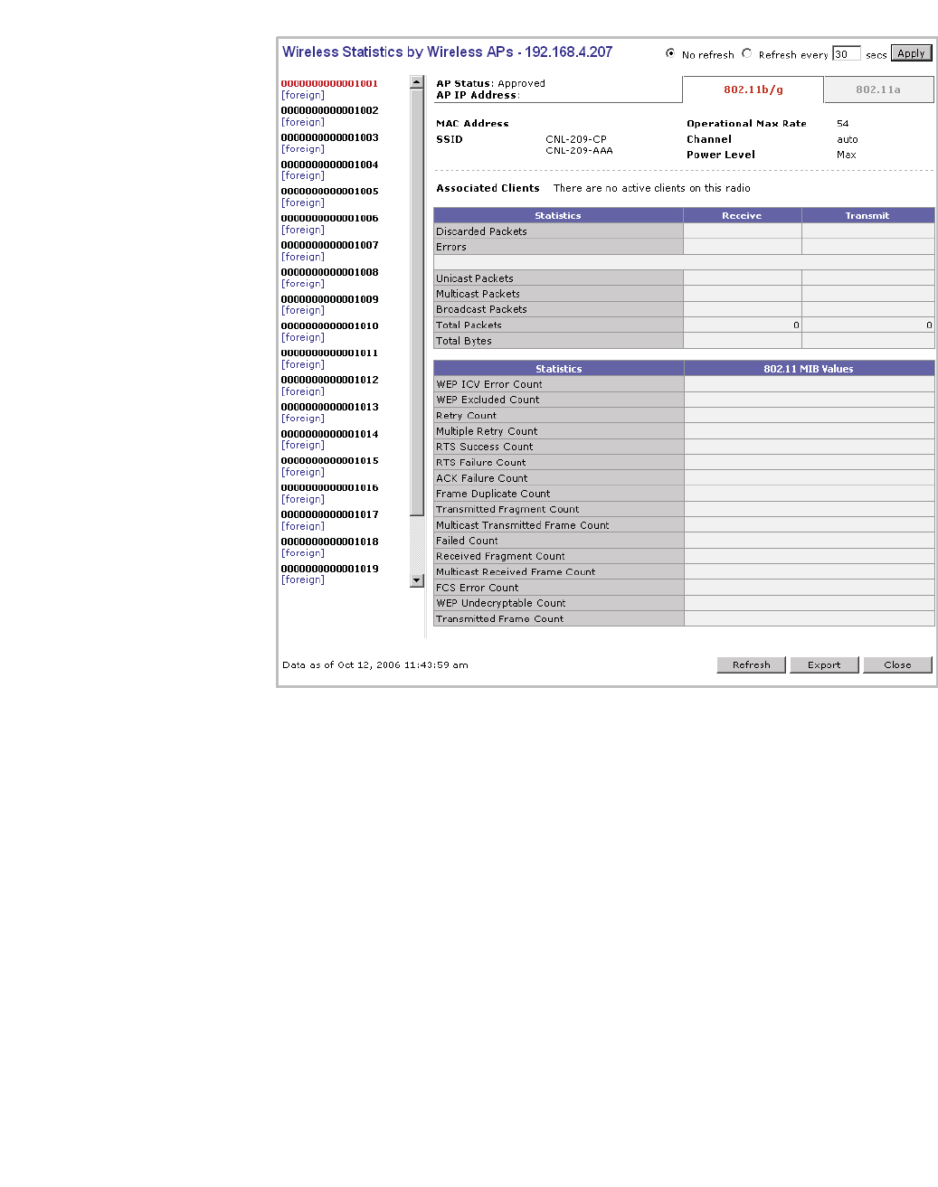
10.1.2 Viewing statistics for Wireless APs
Two displays are snapshots of activity at that point in time on a selected Wireless
AP:
•Wired Ethernet Statistics by Wireless AP
•Wireless Statistics by Wireless AP
The statistics displayed are those defined in the 802.11 MIB, in the IEEE 802.11
standard.
To view wired Ethernet statistics by Wireless AP:
1. From the main menu, click Reports & Displays. The HiPath Reports &
Displays page is displayed.
2. Click the Wired Ethernet Statistics by Wireless AP display option. The
Wired Ethernet Statistics by Wireless APs display opens in a new browser
window.
Working with reports and displays
hwc_reports.fm
Viewing the displays
A31003-W1050-U100-2-7619,March 2008
296 HiPath Wireless Controller, Access Points and Convergence Software V5 R1 , C20/C2400 User Guide
3. In the Wired Ethernet Statistics by Wireless APs display, click a registered
Wireless AP to display its information.
To view Wireless Statistics by Wireless AP:
1. From the main menu, click Reports & Displays. The HiPath Reports &
Displays page is displayed.
2. Click the Wireless Statistics by Wireless AP display option. The Wireless
Statistics by Wireless APs display opens in a new browser window.
hwc_reports.fm
Working with reports and displays
Viewing the displays
A31003-W1050-U100-2-7619, March 2008
HiPath Wireless Controller, Access Points and Convergence Software V5 R1 , C20/C2400 User Guide 297
3. In the Wireless Statistics by Wireless APs display, click a registered
Wireless AP to display its information.
4. Click the appropriate tab to display information for each radio on the Wireless
AP.
5. To view information on selected associated clients, click View Client. The
Associated Clients display opens in a new browser window.
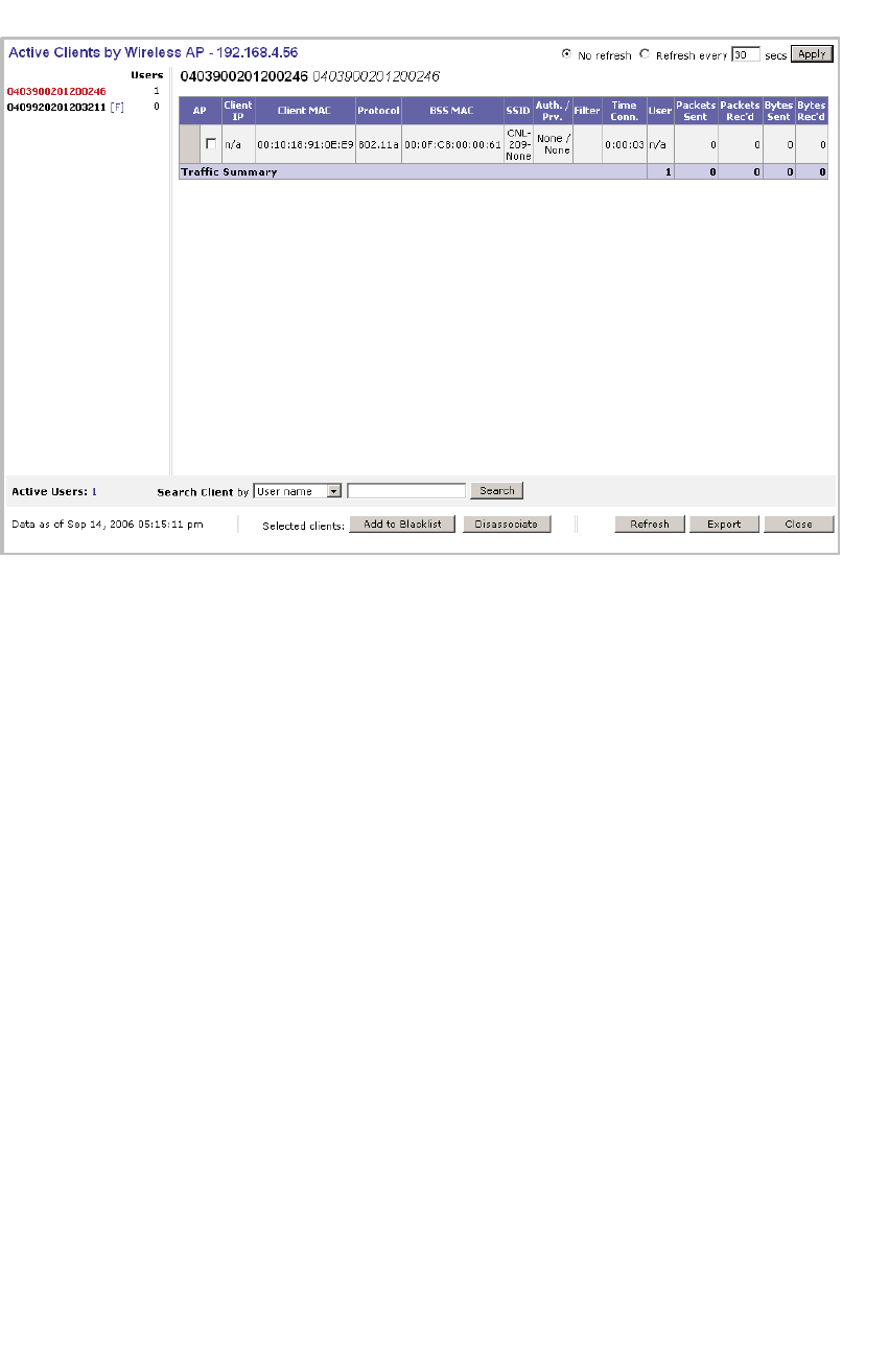
To view Active Clients by Wireless AP statistics:
1. From the main menu, click Reports & Displays. The HiPath Reports &
Displays page is displayed.
2. Click the Active Clients by Wireless APs display option. The Active Clients
by Wireless APs display opens in a new browser window.
Working with reports and displays
hwc_reports.fm
Viewing the displays
A31003-W1050-U100-2-7619,March 2008
298 HiPath Wireless Controller, Access Points and Convergence Software V5 R1 , C20/C2400 User Guide
•Statistics are expressed in respect of the AP. Therefore, Packets Sent means
the AP has sent that data to a client and Packets Rec’d means the AP has
received packets from a client.
•If the client is authenticated, a green check mark icon is displayed in the first
column of the display.
• Time Conn is the length of time that a client has been on the system, not just
on an AP. If the client roams from one AP to another, the session stays,
therefore Time Conn does not reset.
•A client is displayed as soon as the client connects (or after refresh of page).
The client disappears as soon as it times out.
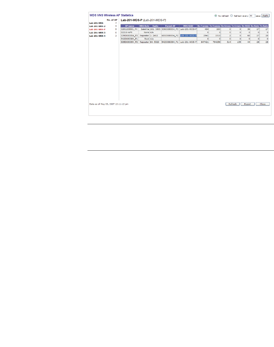
To view WDS Wireless AP Statistics:
1. From the main menu, click Reports & Displays. The HiPath Reports &
Displays page is displayed.
2. Click the WDS Wireless AP Statistics display option. The WDS Wireless
AP Statistics display opens in a new browser window.
hwc_reports.fm
Working with reports and displays
Viewing the displays
A31003-W1050-U100-2-7619, March 2008
HiPath Wireless Controller, Access Points and Convergence Software V5 R1 , C20/C2400 User Guide 299
Note: RSSI value on the WDS VNS Wireless AP Statistics report denotes the
signal strength. The minimum value is 1 and maximum value is 60. The higher
the RSSI value, the stronger the received signal.
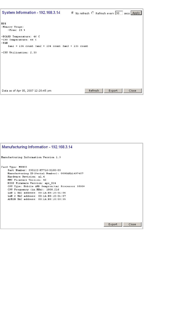
10.1.3 Viewing the System Information and
Manufacturing Infomation displays
System Information – Displays system information including memory usage and
CPU and board temperatures.
Manufacturing Information – Displays manufacturing information including the
card serial number and CPU type and frequency.
To view system information:
1. From the main menu, click Reports & Displays. The HiPath Reports &
Displays page is displayed.
2. Click the System Information display option. The System Information
display opens in a new browser window.
Working with reports and displays
hwc_reports.fm
Viewing the displays
A31003-W1050-U100-2-7619,March 2008
300 HiPath Wireless Controller, Access Points and Convergence Software V5 R1 , C20/C2400 User Guide
To view manufacturing information:
1. From the main menu, click Reports & Displays. The HiPath Reports &
Displays page is displayed.
2. Click the Manufacturing Information display option. The Manufacturing
Information display opens in a new browser window.
10.1.4 Viewing displays for the mobility manager
When a HiPath Wireless Controller has been configured as a mobility manager,
two additional displays appear as options on the HiPath Reports & Displays
page:
• Client Location in Mobility Zone – Displays the active wireless clients and
their status
hwc_reports.fm
Working with reports and displays
Viewing the displays
A31003-W1050-U100-2-7619, March 2008
HiPath Wireless Controller, Access Points and Convergence Software V5 R1 , C20/C2400 User Guide 301
• Mobility Tunnel Matrix – Displays a cross-connection view of the state of
inter-controller tunnels, as well as relative loading for user distribution across
the mobility domain
To view mobility manager displays:
1. From the main menu, click Reports & Displays. The HiPath Reports &
Displays page is displayed.
2. Click the appropriate mobility manager display:
•Client Location in Mobility Zone
•Mobility Tunnel Matrix
The colored status indicates the following:
•Green – The mobility manager is in communication with an agent and the
data tunnel has been successfully established.
• Yellow – The mobility manager is in communication with an agent but the
data tunnel is not yet successfully established.
•Red – The mobility manager is not in communication with an agent and there
is no data tunnel.
Client Location in Mobility Zone
You can do the following:
•Sort this display by home or foreign controller

Working with reports and displays
hwc_reports.fm
Viewing the displays
A31003-W1050-U100-2-7619,March 2008
302 HiPath Wireless Controller, Access Points and Convergence Software V5 R1 , C20/C2400 User Guide
•Search for a client by MAC address, user name, or IP address, and typing the
search criteria in the box
•Define the refresh rates for this display
•Export this information as an xml file
Mobility Tunnel Matrix
•Provides connectivity matrix of mobility state
•Provides a view of:
•Tunnel state
•If a tunnel between controllers is reported down, it is highlighted in red
•If only a control tunnel is present, it is highlighted in yellow
•If data and control tunnels are fully established, it is highlighted in green
•Tunnel Uptime
•Number of clients roamed (Mobility loading)
•Local controller loading
•Mobility membership list
A HiPath Wireless Controller is only removed from the mobility matrix if it is
explicitly removed by the administrator from the Mobility permission list. If a
particular link between controllers, or the controller is down, the corresponding
matrix connections are identified in red color to identify the link.
The Active Clients by VNS report for the controller on which the user is home
(home controller) will display the known user characteristics (IP, statistics, etc.).
On the foreign controller, the Clients by VNS report does not show users that have
roamed from other controllers, since the users remain associated with the home
controller's VNS.
The Active Clients by AP report on each controller will show both the loading of
local and foreign users (users roamed from other controllers) that are taking
resources on the AP.
Note: The statistics from the mobility manager are updated every thirty seconds,
regardless of the refresh period for the displays.

hwc_reports.fm
Working with reports and displays
Viewing reports
A31003-W1050-U100-2-7619, March 2008
HiPath Wireless Controller, Access Points and Convergence Software V5 R1 , C20/C2400 User Guide 303
10.2 Viewing reports
The following reports are available in the HiPath Wireless Controller, Access
Points and Convergence Software system:
•Forwarding Table (routes defined on the Routing Protocols pages)
•OSPF Neighbor (if OSPF is enabled on the Routing Protocols pages)
•OSPF Linkstate (if OSPF is enabled on the Routing Protocols pages)
•AP Inventory (a consolidated summary of Wireless AP setup)
To view reports:
1. From the main menu, click Reports & Displays. The HiPath Reports &
Displays page is displayed.
2. In the Reports list, click the report you want to view:
•Forwarding Table
•OSPF Neighbor
•OSPF Linkstate
•AP Inventory
Note: The AP Inventory report opens in a new browser window. All other
reports appear in the current browser window.
The following is an example of a Forwarding Table report:
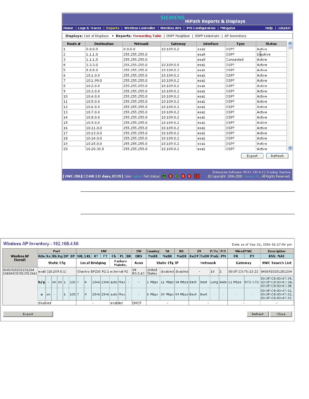
Working with reports and displays
hwc_reports.fm
Viewing reports
A31003-W1050-U100-2-7619,March 2008
304 HiPath Wireless Controller, Access Points and Convergence Software V5 R1 , C20/C2400 User Guide
Note: If you open only automatically refreshed reports, the Web management
session timer will not be updated or reset. Your session will eventually timeout.
The following is an example of the AP Inventory report:
The following is a description of the column names and abbreviations found in the
AP Inventory report:
•Rdo – Radio
•Ra – 802.11a radio. The data entry for an Wireless AP indicates whether the
a radio is on or off.

hwc_reports.fm
Working with reports and displays
Viewing reports
A31003-W1050-U100-2-7619, March 2008
HiPath Wireless Controller, Access Points and Convergence Software V5 R1 , C20/C2400 User Guide 305
•Rb – 802.11b protocol enabled. Possible values are on or off.
•Rg – 802.11g protocol enabled. Possible values are on or off.
•DP – DTIM period
•BP – Beacon Period
•SRL – Short Retry Limit
•LRL – Long Retry Limit
•RT – RTS Threshold
•FT – Fragmentation Threshold
•Ch – Channel served by the corresponding radio.
•PL – Power Level (Defined in the Wireless AP radio properties pages.)
•BR – Basic Rate (Only applies to Wireless APs running 3.1 or earlier.)
•ORS – Operational Rate Set (Only applies to Wireless APs running 3.1 or
earlier.)
•MnBR – Minimum Basic Rate (For more information, see the Wireless AP
radio configuration tabs.)
•MxBR – Maximum Basic Rate
•MxOR – Maximum Operational Rate
•RxDV – Receive Diversity
•TxDV – Tx Diversity
•Pmb – Preamble (long, short)
•PM – Protection Mode
•PR – Protection Rate
•PT – Protection Type
•BSS – Basic Service Set
•MAC – MAC address
•BSS: MAC – Also called BSSID, this is the MAC address of a (virtual)
wireless interface on which the Wireless AP serves a BSS/VNS. There could
be 8 per radio.
•Port – Ethernet Port and associated IP address of the interface on the HiPath
Wireless Controller through which the Wireless AP communicates.
•HW – Hardware version of the Wireless AP.
•SW – Software version executing on theWireless AP.

Working with reports and displays
hwc_reports.fm
Viewing reports
A31003-W1050-U100-2-7619,March 2008
306 HiPath Wireless Controller, Access Points and Convergence Software V5 R1 , C20/C2400 User Guide
•TA – Telnet access (enabled or disabled).
•BD – Broadcast disassociation (enabled or disabled). If enabled, whenever
the Wireless AP is going offline in a controlled fashion it will send the
disassociation frame to all its clients as a broadcast.
•DV – Diversity
•P/To – Poll timeout. If polling is enabled, a numeric value.
•P/I – Poll interval. If polling is enabled, a numeric value.
•Wired MAC – The physical address of the Wireless AP's wired Ethernet
interface.
• Description – As defined on the AP Properties page.
•Failure Maintn. – Maintain MU sessions on Wireless AP when the Wireless
AP loses the connection to the HiPath Wireless Controller.
•Assn – Assignment (address assignment method)
•Static Cfg – Wireless AP's IP address if statically configured (same as the
Static Values radio button on the AP Static Configuration page).
•Static Cfg IP – Statically Configured IP. If the Wireless AP's IP address is
configured statically, the IP address is displayed.
•Netmask – If the Wireless AP's IP address is configured statically, the
netmask that is statically configured for the Wireless AP.
• Gateway – If the Wireless AP's IP address is configured statically, the IP
address of the gateway router that the Wireless AP will use.
• HWC Search List – The list of IP addresses that the Wireless AP is
configured to try to connect to in the event that the current connection to the
HiPath Wireless Controller is lost.
To export and save a report in XML:
1. On the report page, click Export. A Windows File Download dialog is
displayed.
2. Click Save. A Windows Save As dialog is displayed.
Note: If your default XML viewer is Internet Explorer or Netscape, clicking
Open will open the exported data to your display page. You must right-click
to go back to the export display. The XML data file will not be saved to your
local drive.
3. Browse to the location where you want to save the exported XML data file,
and in the File name box enter an appropriate name for the file.
4. Click Save. The XML data file is saved in the specified location.

hwc_reports.fm
Working with reports and displays
Viewing reports
A31003-W1050-U100-2-7619, March 2008
HiPath Wireless Controller, Access Points and Convergence Software V5 R1 , C20/C2400 User Guide 307

Working with reports and displays
hwc_reports.fm
Viewing reports
A31003-W1050-U100-2-7619,March 2008
308 HiPath Wireless Controller, Access Points and Convergence Software V5 R1 , C20/C2400 User Guide

hwc_ongoing.fm
A31003-W1050-U100-2-7619, March 2008
HiPath Wireless Controller, Access Points and Convergence Software V5 R1 , C20/C2400 User Guide 309
Performing system maintenance
Performing Wireless AP client management
11 Performing system maintenance
This chapter describes system maintenance processes, including:
•Performing Wireless AP client management
•Resetting the Wireless APs to their factory default settings
•Performing system maintenance tasks
•Performing HiPath Wireless Controller software maintenance
•Working with system logs, trace messages, and audits
11.1 Performing Wireless AP client management
There are times when for service reasons or security issues, you want to cut the
connection with a particular wireless device. You can view all the associated
wireless devices, by MAC address, on a selected Wireless AP. You can do the
following:
•Disassociate a selected wireless device from its Wireless AP.
•Add a selected wireless device's MAC address to a blacklist of wireless
clients that will not be allowed to associate with the Wireless AP.
•Backup and restore the HiPath Wireless Controller database. For more
information, see Section 11.4, “Performing HiPath Wireless Controller
software maintenance”, on page 320.
11.1.1 Disassociating a client
In addition to the following procedure below, you can also disassociate wireless
users directly from the Active Clients by VNS page. For more information, see
Chapter 10, “Working with reports and displays”.
To disassociate a wireless device client:
1. From the main menu, click Wireless AP Configuration. The Wireless AP
Configuration page is displayed.
2. From the left pane, click Client Management. The Disassociate tab is
displayed.
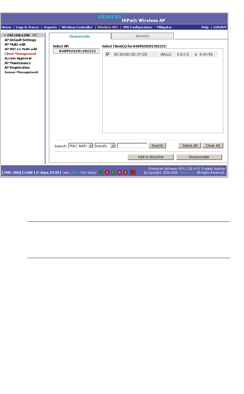
Performing system maintenance
hwc_ongoing.fm
Performing Wireless AP client management
A31003-W1050-U100-2-7619,March 2008
310 HiPath Wireless Controller, Access Points and Convergence Software V5 R1 , C20/C2400 User Guide
3. In the Select AP list, click the AP you want to disassociate.
4. In the Select Client(s) list, select the checkbox next to the client you want to
disassociate.
Note: You can search for a client by MAC Address, IP Address or User ID, by
selecting the search parameters from the drop-down lists and typing a search
string in the Search box and clicking Search. You can also use the Select All
or Clear All buttons to help you select multiple clients.
5. Click Disassociate. The client's session terminates immediately.
11.1.2 Blacklisting a client
The Blacklist tab displays the current list of MAC addresses that are not allowed
to associate. A client is added to the blacklist by selecting it from a list of
associated APs or by typing its MAC address.
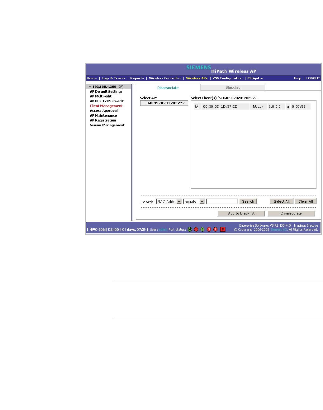
hwc_ongoing.fm
Performing system maintenance
Performing Wireless AP client management
A31003-W1050-U100-2-7619, March 2008
HiPath Wireless Controller, Access Points and Convergence Software V5 R1 , C20/C2400 User Guide 311
To blacklist a wireless device client:
1. From the main menu, click Wireless AP Configuration. The Wireless AP
Configuration page is displayed.
2. From the left pane, click Client Management. The Disassociate tab is
displayed.
3. In the Select AP list, click the AP you want to disassociate.
4. In the Select Client(s) list, select the checkbox next to the client you want to
disassociate, if applicable.
Note: You can search for a client by MAC Address, IP Address or User ID, by
selecting the search parameters from the drop-down lists and typing a search
string in the Search box and clicking Search. You can also use the Select All
or Clear All buttons to help you select multiple clients.
5. Click Add to Blacklist. The selected wireless client's MAC address is added
to the blacklist.
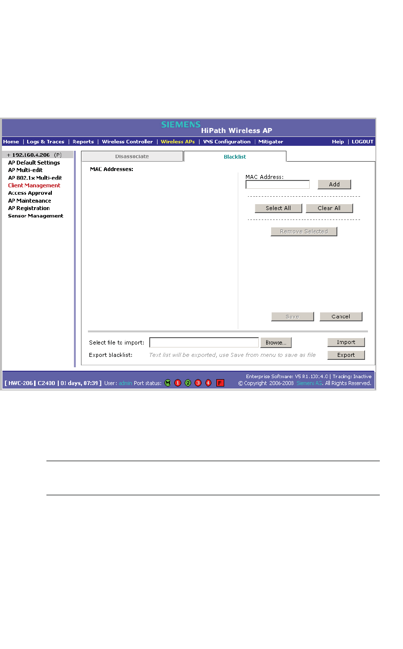
Performing system maintenance
hwc_ongoing.fm
Performing Wireless AP client management
A31003-W1050-U100-2-7619,March 2008
312 HiPath Wireless Controller, Access Points and Convergence Software V5 R1 , C20/C2400 User Guide
To blacklist a wireless device client using its MAC address:
1. From the main menu, click Wireless AP Configuration. The Wireless AP
Configuration page is displayed.
2. From the left pane, click Client Management. The Disassociate tab is
displayed.
3. Click the Blacklist tab.
4. To add a new MAC address to the blacklist, in the MAC Address box type the
client’s MAC address.
5. Click Add. The client is displayed in the MAC Addresses list.
Note: You can use the Select All or Clear All buttons to help you select
multiple clients.
6. To save your changes, click Save.
To clear an address from the blacklist:
1. From the main menu, click Wireless AP Configuration. The Wireless AP
Configuration page is displayed.
2. From the left pane, click Client Management. The Disassociate tab is
displayed.

hwc_ongoing.fm
Performing system maintenance
Resetting the Wireless APs to their factory default settings
A31003-W1050-U100-2-7619, March 2008
HiPath Wireless Controller, Access Points and Convergence Software V5 R1 , C20/C2400 User Guide 313
3. Click the Blacklist tab.
4. To clear an address from the blacklist, select the corresponding checkbox in
the MAC Addresses list.
5. Click Remove Selected. The selected client is removed from the list.
Note: You can use the Select All or Clear All buttons to help you select
multiple clients.
6. To save your changes, click Save.
To import a list of MAC addresses for the blacklist:
1. From the main menu, click Wireless AP Configuration. The Wireless AP
Configuration page is displayed.
2. From the left pane, click Client Management. The Disassociate tab is
displayed.
3. Click the Blacklist tab.
4. Click Browse and navigate to the file of MAC addresses you want to import
and add to the blacklist.
5. Click the file, and then click Import. The list of MAC addresses is imported.
To export a list of MAC addresses for the blacklist:
1. From the main menu, click Wireless AP Configuration. The Wireless AP
Configuration page is displayed.
2. From the left pane, click Client Management. The Disassociate tab is
displayed.
3. Click the Blacklist tab.
4. To export the current blacklist, use the browser’s save option to save the file
as a text (.txt) file. It is recommend that a descriptive file name is used.
5. Click Export. The saved blacklist file is exported.
11.2 Resetting the Wireless APs to their factory default settings
You can reset the HiPath Wireless AP and the HiPath Wireless Outdoor AP to
their factory default settings.

Performing system maintenance
hwc_ongoing.fm
Resetting the Wireless APs to their factory default settings
A31003-W1050-U100-2-7619,March 2008
314 HiPath Wireless Controller, Access Points and Convergence Software V5 R1 , C20/C2400 User Guide
11.2.1 Resetting the HiPath Wireless AP to its factory
default settings
The AP boot-up sequence includes a random delay interval, followed by a
vulnerable time interval. During the vulnerable time interval (2 seconds), the
LEDs flash in a particular sequence to indicate that the HiPath Wireless Controller
is in the vulnerable time interval. For more information, see Section 4.2.3.1,
“HiPath Wireless AP LED status”, on page 74.
If you power up the AP and interrupt the power during the vulnerable time interval
three consecutive times, the next time the AP reboots, it will restore its factory
defaults including the user password and the default IP settings.
Caution: The restoration of factory default settings does not erase the
non-volatile log.
To reset the HiPath Wireless AP to its factory default settings:
1. Switch off, and then switch on the HiPath Wireless AP. The HiPath Wireless
AP reboots.
2. Switch off, and then switch on the HiPath Wireless AP during the vulnerable
time interval.
Note: You should refer to the HiPath Wireless AP’s LED pattern to determine
the vulnerable period. For more information, see Section 4.2.3.1, “HiPath
Wireless AP LED status”.
3. Repeat Step 2 two more times.
When the HiPath Wireless AP reboots for the fourth time, after having its
power supply interrupted three consecutive times, it restores its factory
default settings. The HiPath Wireless AP then reboots again to put the default
settings into effect.
Note: You should refer to the HiPath Wireless AP’s LED pattern to confirm
that the HiPath Wireless AP is set to its factory defaults. For more information,
see Section 4.2.3.1, “HiPath Wireless AP LED status”.
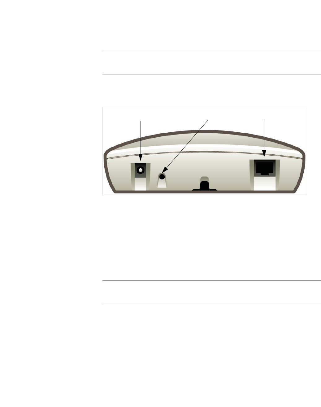
hwc_ongoing.fm
Performing system maintenance
Resetting the Wireless APs to their factory default settings
A31003-W1050-U100-2-7619, March 2008
HiPath Wireless Controller, Access Points and Convergence Software V5 R1 , C20/C2400 User Guide 315
Reset button (Hardware)
Some models of the HiPath Wireless AP have a reset button. If your model is
equipped with a reset button, you can set it to its factory default settings by
pressing and holding the reset button for approximately six seconds.
Note: If you press the reset button and do not hold it over six seconds, the HiPath
Wireless AP will merely reboot, and not reset to its factory defaults.
The following figure illustrates the location of the reset button on the HiPath
Wireless APs.
Figure 20 Position of the reset button in the HiPath Wireless AP
11.2.1.1 Resetting the HiPath Wireless Outdoor AP to its
factory default settings
All models of the HiPath Wireless Outdoor AP have a reset button.
You can set the HiPath Wireless Outdoor AP to its factory default settings by
pressing and holding the reset button for approximately six seconds.
Note: If you press the reset button and do not hold it over six seconds, the HiPath
Wireless Outdoor AP will merely reboot, and not reset to its factory defaults.
The following figure illustrates the location of the reset button on the HiPath
Wireless Outdoor AP.
AC/DC Power Supply Ethernet Port
Reset Button

Performing system maintenance
hwc_ongoing.fm
Resetting the Wireless APs to their factory default settings
A31003-W1050-U100-2-7619,March 2008
316 HiPath Wireless Controller, Access Points and Convergence Software V5 R1 , C20/C2400 User Guide
Figure 21 Position of the reset button with the housing cover removed
Attention: The reset button is located below the housing cover beside the
sockets for the external antennas. To access the reset button, you must remove
the housing cover. For more information, see the HiPath Wireless Outdoor AP
Installation Guide.
11.2.1.2 Resetting the HiPath Wireless 802.11n AP to its factory
default settings
You can set the HiPath Wireless 802.11n AP to its factory default settings by
pressing and holding the reset button for approximately four seconds.
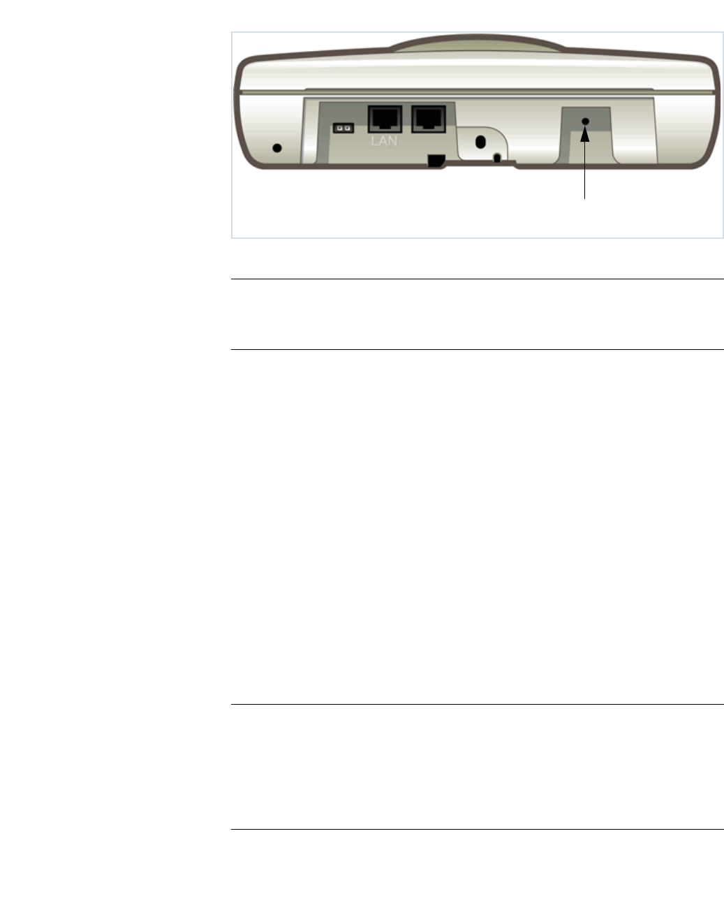
hwc_ongoing.fm
Performing system maintenance
Performing system maintenance tasks
A31003-W1050-U100-2-7619, March 2008
HiPath Wireless Controller, Access Points and Convergence Software V5 R1 , C20/C2400 User Guide 317
Figure 22 Position of the reset button in the HiPath Wireless 802.11n AP
Note: If you press the reset button and do not hold it over four seconds, the
HiPath Wireless 802.11n AP will merely reboot, and not reset to its factory
defaults.
11.3 Performing system maintenance tasks
You can perform various maintenance tasks, including:
•Changing the log level
•Setting a poll interval for checking the status of the Wireless APs (Health
Checking)
•Enabling and defining parameters for Syslog event reporting
•Forcing an immediate system shutdown, with or without reboot
Syslog event reporting uses the syslog protocol to relay event messages to a
centralized event server on your enterprise network. In the protocol a device
generates messages, a relay receives and forwards the messages, and a
collector (a syslog server) receives the messages without relaying them.
Note: The log statements Low water mark level was reached and Incoming
message dropped, because of the rate limiting mechanism indicate that
there is a burst of log messages coming to the event server and the processing
speed is slower than the incoming rate of log messages. These messages do not
indicate that the system is impaired in any way. For more information, see Section
11.5.1, “Logs, traces, audits, and DHCP messages”, on page 342.
Reset Button
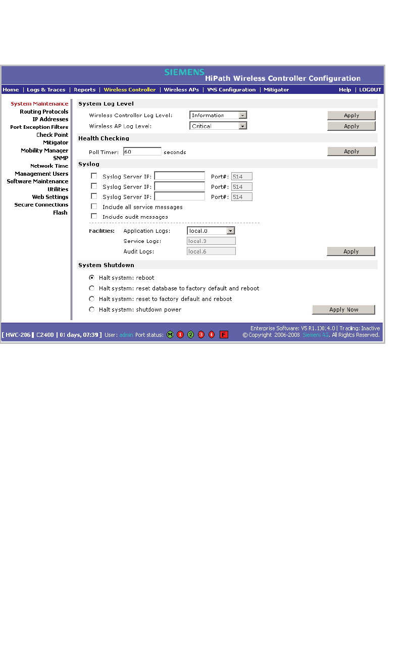
Performing system maintenance
hwc_ongoing.fm
Performing system maintenance tasks
A31003-W1050-U100-2-7619,March 2008
318 HiPath Wireless Controller, Access Points and Convergence Software V5 R1 , C20/C2400 User Guide
To change the log levels:
1. From the main menu, click Wireless Controller Configuration. The
Wireless Controller Configuration page is displayed.
2. In the System Log Level section, from the Wireless Controller Log Level
drop-down list, select the least severe log level for the Controller that you
want to receive: Information,Minor,Major,Critical. For example, if you
select Minor, you receive all Minor,Major and Critical messages. If you
select Major you receive all Major and Critical messages. The default is
Information.
3. Click Apply.
4. From the Wireless AP Log Level drop-down list, select the least severe log
level for the AP that you want to receive: Information,Minor,Major,Critical.
The default is Critical.
5. Click Apply.
To set a poll interval:
1. From the main menu, click Wireless Controller Configuration. The
Wireless Controller Configuration page is displayed.
2. In the Health Checking section, in the Poll Timer box, type the time interval
(in seconds) for the HiPath Wireless Controller to check that each Wireless
AP is connected. The default is 60 seconds.

hwc_ongoing.fm
Performing system maintenance
Performing system maintenance tasks
A31003-W1050-U100-2-7619, March 2008
HiPath Wireless Controller, Access Points and Convergence Software V5 R1 , C20/C2400 User Guide 319
3. Click Apply.
To enable and define parameters for Syslog:
1. From the main menu, click Wireless Controller Configuration. The
Wireless Controller Configuration page is displayed.
2. In the Syslog section, to enable the Syslog function for up to three syslog
servers, select the appropriate checkboxes.
3. For each enabled syslog server, in the IP box, type a valid IP address for the
server on the network.
4. For each enabled syslog server, in the Port # box, type a valid port number
to connect on. The default port for syslog is 514.
5. To include all system messages, select the Include all service messages
checkbox. If the box is not selected, only component messages (logs and
traces) are relayed. This setting applies to all three servers. The additional
service messages are:
•DHCP messages reporting users receiving IP addresses
•Startup Manager Task messages reporting component startup and
failure
6. To include audit messages, select the Include audit messages checkbox.
7. From the Application Logs drop-down list, select the log level (local.0 -
local.6) to be sent to the syslog server. This setting applies all three servers.
8. If the Include all service messages checkbox is selected, the Service Logs
drop-down list becomes selectable. Select the log level (local.0 - local.6) to
be sent to the syslog server. This setting applies all three servers.
9. If you selected the Include audit messages checkbox, the Audit Logs
drop-down list becomes available. Select the log level (local.0 - local.6) to be
sent to the syslog server. This setting applies all three servers.
10. To apply your changes, click Apply.
Note: The syslog daemon must be running on both the HiPath Wireless
Controller and on the remote syslog server before the logs can be
synchronized. If you change the log level on the HiPath Wireless Controller,
you must also modify the appropriate setting in the syslog configuration on
remote syslog server.
Table 28 displays Syslog and Controller, Access Points and Convergence
Software event log mapping.

Performing system maintenance
hwc_ongoing.fm
Performing HiPath Wireless Controller software maintenance
A31003-W1050-U100-2-7619,March 2008
320 HiPath Wireless Controller, Access Points and Convergence Software V5 R1 , C20/C2400 User Guide
To force an immediate system shutdown:
1. From the main menu, click Wireless Controller Configuration. The
Wireless Controller Configuration page is displayed.
2. To shut down the system, including associated Wireless APs, select the
appropriate shut down option:
• Halt system: reboot
• Halt system: reset database to factory default and reboot – Restores
all aspects of the system configuration to the initial settings. However, the
Management IP address and license key are preserved. This permits the
user to remain connected through the Management interface.
• Halt system: reset to factory default and reboot – Resets the entire
system configuration to the factory shipping state. The Management IP
address reverts to 192.168.10.1 and the license key is removed.
• Halt system – The system enters the halted state, which stops all
functional services and the application. To restart the system, the power
to the system must be reset.
3. Click Apply Now. The system is immediately halted.
11.4 Performing HiPath Wireless Controller software maintenance
Software Maintenance can include the following administrator tasks:
•Working with a flash memory card
•Upgrading HiPath Wireless Controller software
•Backing up the HiPath Wireless Controller database
•Restoring the HiPath Wireless Controller database
•Maintaining the HiPath Wireless Controller product license keys
Syslog Event Controller, Access Points and Convergence
Software Event
LOG_CRIT Critical
LOG_ERR Major
LOG_WARNING Minor
LOG_INFO Information
LOG_DEBUG Trace
Table 28 Syslog and Controller, Access Points and Convergence Software
event log mapping

hwc_ongoing.fm
Performing system maintenance
Performing HiPath Wireless Controller software maintenance
A31003-W1050-U100-2-7619, March 2008
HiPath Wireless Controller, Access Points and Convergence Software V5 R1 , C20/C2400 User Guide 321
11.4.1 Working with a flash memory card
The HiPath Wireless Controller C2400 supports the use of a flash memory card
to store your system’s image files.
Note: To use the flash memory card capabilities of the HiPath Wireless Controller
C2400, you must remove the cover of the flash memory card from the HiPath
Wireless Controller and then insert a flash memory card. A flash memory card is
not shipped with your HiPath Wireless Controller 2400. For more information, see
the HiPath Wireless Controller, Access Points and Convergence Software
Controller C2400 Installation Instructions.
When working with a flash memory card, use the HiPath Wireless Assistant to:
• Mount the flash memory card – By mounting the flash memory card, you
make the flash memory card that has been inserted into the HiPath Wireless
Controller 2400 available for use.
• Unmount the flash memory card – By unmounting the flash memory card,
you make the flash memory card that has been inserted into the HiPath
Wireless Controller 2400 unavailable for use.
Caution: You must always unmount the flash memory card via the HiPath
Wireless Assistant before removing it from the HiPath Wireless Controller.
Failure to do so may corrupt the files on the flash card.
• Delete files stored on the flash memory card – By deleting files stored on
the flash memory card, you make additional space on the flash memory card
available.
To mount a flash memory card:
1. From the main menu, click Wireless Controller Configuration. The
Wireless Controller Configuration page is displayed.
2. From the left pane, click Flash. The Flash Memory page is displayed.
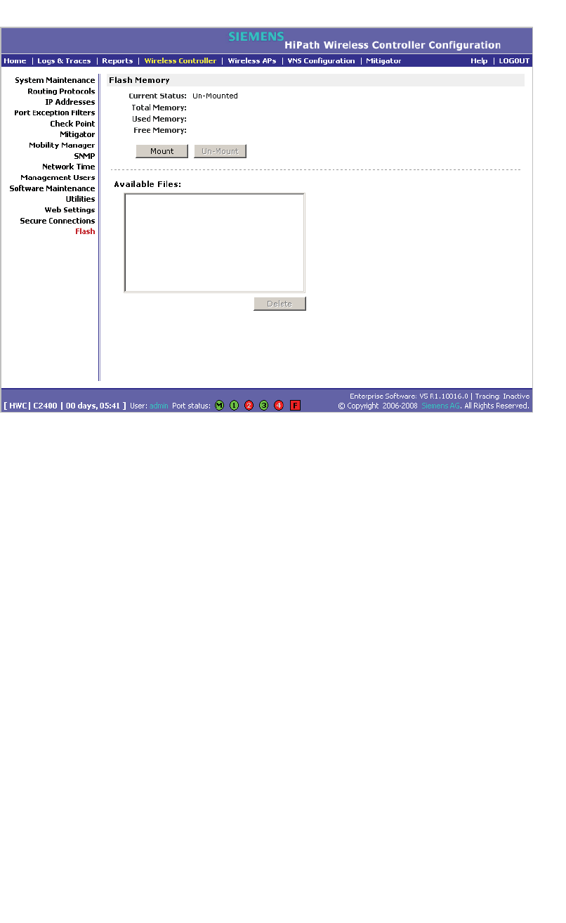
Performing system maintenance
hwc_ongoing.fm
Performing HiPath Wireless Controller software maintenance
A31003-W1050-U100-2-7619,March 2008
322 HiPath Wireless Controller, Access Points and Convergence Software V5 R1 , C20/C2400 User Guide
3. Click Mount, and then click Ok to confirm the flash memory card mount. Once
the mounting process is complete, the flash memory space is displayed and
the files contained on the flash memory card are listed in the Available Files
box.
To unmount a flash memory card:
1. From the main menu, click Wireless Controller Configuration. The
Wireless Controller Configuration page is displayed.
2. From the left pane, click Flash. The Flash Memory page is displayed. The
mounted flash memory space is displayed and the Available Files box
displays any files located on the flash memory card.
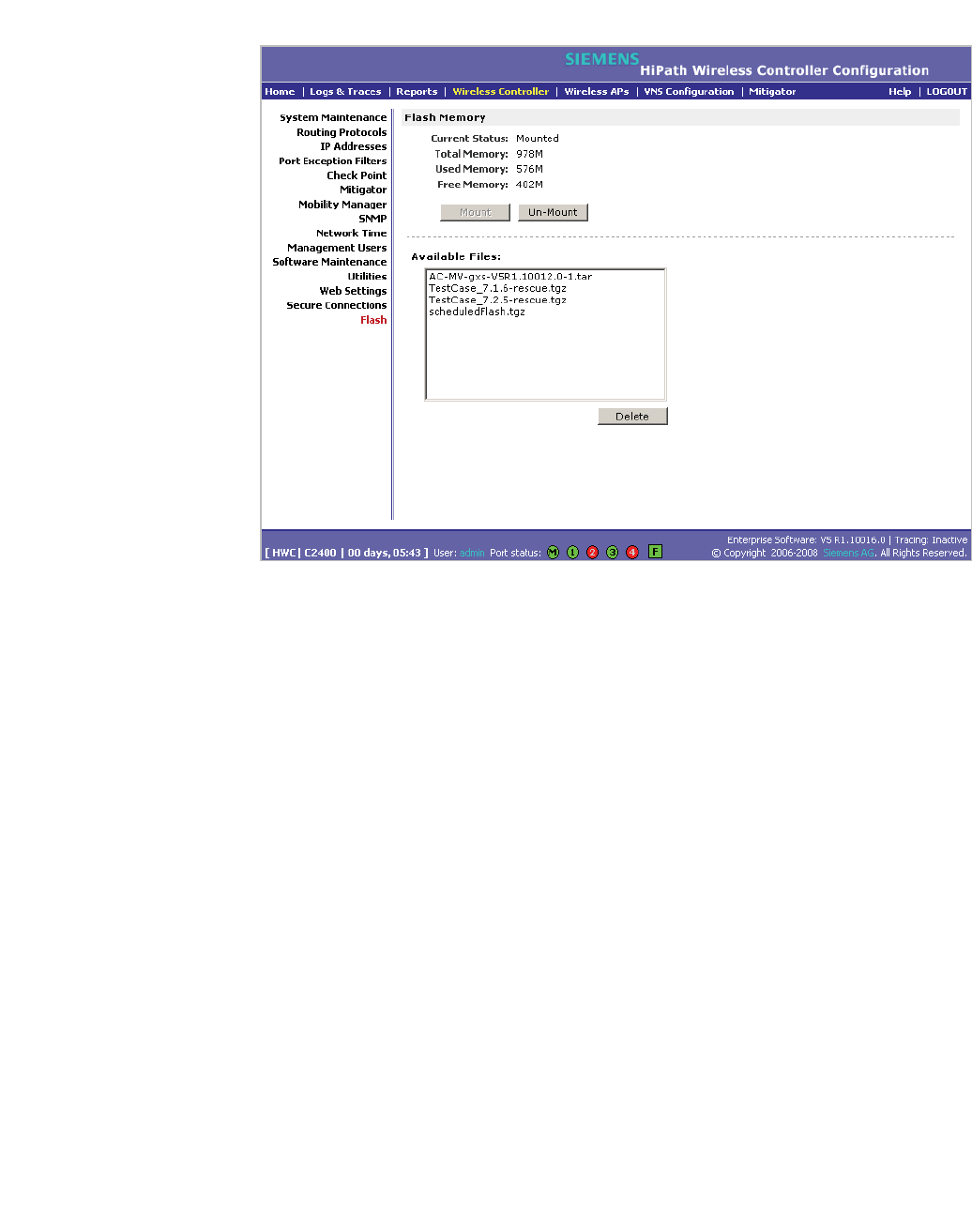
hwc_ongoing.fm
Performing system maintenance
Performing HiPath Wireless Controller software maintenance
A31003-W1050-U100-2-7619, March 2008
HiPath Wireless Controller, Access Points and Convergence Software V5 R1 , C20/C2400 User Guide 323
3. Click Un-Mount, and then click Ok to confirm the flash memory card
unmount. Once the unmounting process is complete, the Flash Memory
page is refreshed and no longer displays any of the flash memory information.
To delete a flash memory card:
1. From the main menu, click Wireless Controller Configuration. The
Wireless Controller Configuration page is displayed.
2. From the left pane, click Flash. The Flash Memory page is displayed. The
mounted flash memory space is displayed and the Available Files box
displays any files located on the flash memory card.
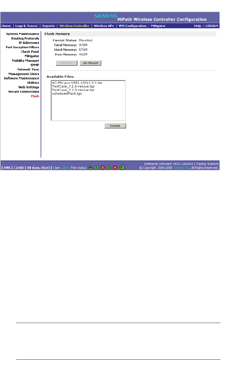
Performing system maintenance
hwc_ongoing.fm
Performing HiPath Wireless Controller software maintenance
A31003-W1050-U100-2-7619,March 2008
324 HiPath Wireless Controller, Access Points and Convergence Software V5 R1 , C20/C2400 User Guide
3. In the Available Files box, click the file you want to delete, and then click
Delete.
4. To confirm the file deletion from the flash memory card, click Ok. The file is
deleted.
11.4.2 Upgrading HiPath Wireless Controller software
When you upgrade HiPath Wireless Controller software, you have the following
options:
•Upgrade using a local or remote image file:
•A local image file can be stored on the HiPath Wireless Controller or on a
flash memory card.
•Perform the upgrade now or schedule the upgrade for a future date
•Backup the current system image
Note: In order to access an FTP server during either the remote upgrade, remote
backup, or remote restore processes, ensure that the HiPath Wireless
Controller’s Management port is phsysically connected to the network and that
the FTP server and Management port share the same network segment.

hwc_ongoing.fm
Performing system maintenance
Performing HiPath Wireless Controller software maintenance
A31003-W1050-U100-2-7619, March 2008
HiPath Wireless Controller, Access Points and Convergence Software V5 R1 , C20/C2400 User Guide 325
In the V5 release, you can upgrade from any past release, starting from
V4 R1.5.x, directly to the new release without having to apply intermediate
upgrades. The upgrade procedure can be initiated using the HiPath Wireless
Assistant or via CLI commands.
Note: To upgrade to version V5, a HiPath Wireless Controller running an earlier
software version than V4 R1.5.x (such as V3.1 GPx, V4R0 GA, or V4R0 GP1 etc.)
must first be upgraded to the minimum supported version of V4 R1.5.x.
Note: If you are upgrading the two HiPath Wireless Controllers in ‘Availability’
mode, you must ensure that both of them are running the same version of the
software.
Unlike previous releases, V5 is provided as a single TAR (.tar) package.
11.4.2.1 Upgrading using a local or remote image file
When you upgrade HiPath Wireless Controller software, two upgrade scenarios
are available:
• Local – A local upgrade involves upgrading the HiPath Wireless Controller
using an image file (.tar) that is located on the HiPath Wireless Controller or
flash memory card.
•Remote – A remote upgrade involves upgrading the HiPath Wireless
Controller using an image file that is located on an external FTP server. If the
image file (.tar) you want is located on an external FTP server, you have the
following two options:
•Launch the upgrade with the image file remaining on the external FTP
server.
•First download the remote image file onto the HiPath Wireless Controller
or flash memory card, and then perform the HiPath Wireless Controller
upgrade.
To perform a local upgrade of HiPath Wireless Controller software:
1. From the main menu, click Wireless Controller Configuration. The
Wireless Controller Configuration page is displayed.
2. From the left pane, click Software Maintenance. The HWC Software tab is
displayed.
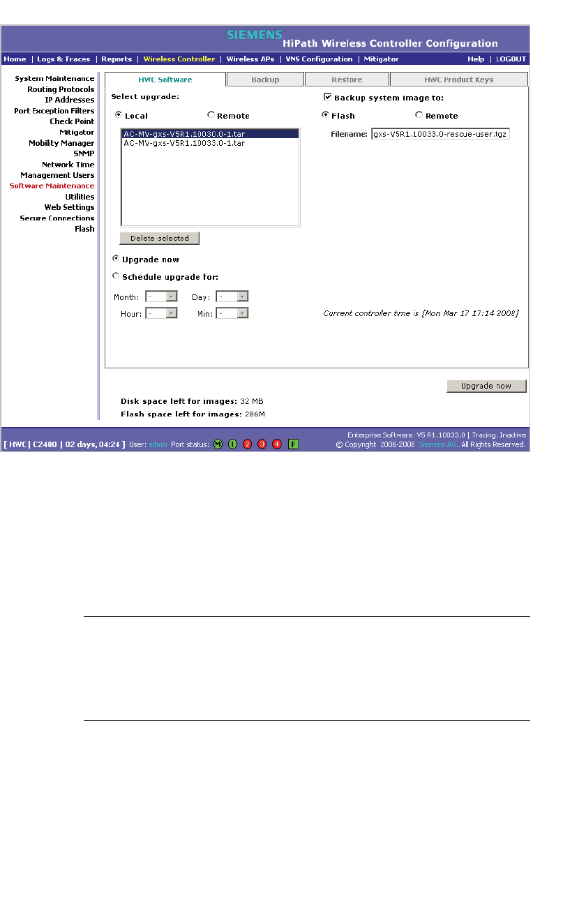
Performing system maintenance
hwc_ongoing.fm
Performing HiPath Wireless Controller software maintenance
A31003-W1050-U100-2-7619,March 2008
326 HiPath Wireless Controller, Access Points and Convergence Software V5 R1 , C20/C2400 User Guide
3. Select Local, and then click the image file you want to upgrade to from the
Select upgrade list.
4. If applicable, backup the current system image:
•To save the backup image locally, select the Flash option, and then type
a file name for the backup image in the Filename box. The filename must
end with the .tgz extension.
Note: If you are performing an upgrade on a HiPath Wireless Controller
C20, the Flash option is not available. Instead, to save the backup image
locally, select the Local option. The Filename box is populated with the
automatically generated file name for the backup image. You cannot edit
the file name of the backup image file.
•To save the backup image on a remote FTP server, select the Remote
option, and then type the following:
•FTP Server – The IP address of the FTP server that will store the
image file.
•User ID – The user ID used to log in to the FTP server.
• Password – The corresponding password for the user ID.

hwc_ongoing.fm
Performing system maintenance
Performing HiPath Wireless Controller software maintenance
A31003-W1050-U100-2-7619, March 2008
HiPath Wireless Controller, Access Points and Convergence Software V5 R1 , C20/C2400 User Guide 327
• Confirm – The corresponding password for the user ID, to confirm it
was typed correctly.
•Directory – The directory on the server in which the image file is to
be stored.
•Filename – The name of the image file.The filename must end with
the .tgz extension.
5. If applicable, clear the Backup system image to option if you do not want to
save a backup image of your current system.
Caution: You should always backup your current system during the upgrade
process. Having a backup image of your system provides you the option of
restoring your system to its previous configuration, if needed.
6. Do one of the following:
•To schedule a backup, select the Schedule upgrade for option.
a) Use the Month,Day,Hour, and Minute drop-down lists to schedule
the upgrade.
b) Click Schedule upgrade.
c) Review the upgrade settings in the dialog box that is displayed. If
correct, click OK to confirm the upgrade. Once you confirm the
upgrade, the HWC Software tab fields become grayed out.
Note: A scheduled upgrade is not a recurring event. The HiPath Wireless
Controller only allows one scheduled upgrade to be scheduled at a time.
•To perform the upgrade now, select the Upgrade now option.
a) Click the Upgrade now button.
b) Review the upgrade settings in the dialog box that is displayed. If
correct, click OK to confirm the upgrade. Once you confirm the
upgrade, all sessions are closed. The Software maintenance window
is displayed, providing the status of the upgrade. The previous
software is uninstalled automatically. The new software is installed.
The HiPath Wireless Controller reboots automatically. The database
is updated and migrated.
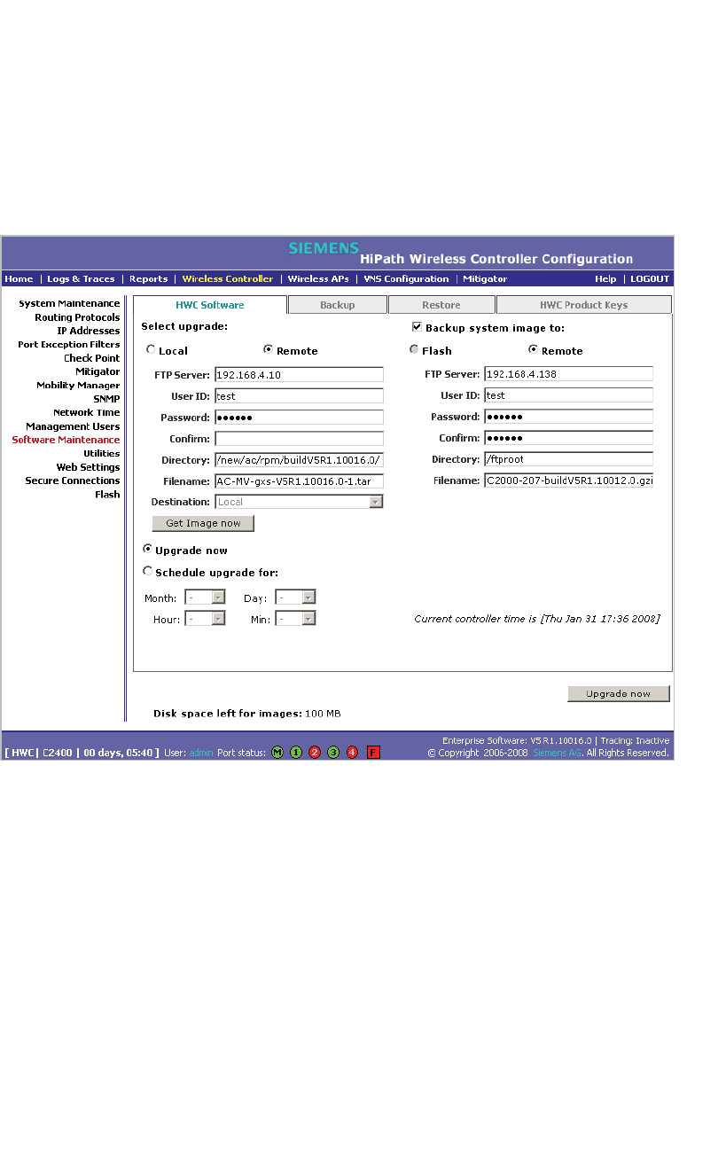
Performing system maintenance
hwc_ongoing.fm
Performing HiPath Wireless Controller software maintenance
A31003-W1050-U100-2-7619,March 2008
328 HiPath Wireless Controller, Access Points and Convergence Software V5 R1 , C20/C2400 User Guide
To perform a remote upgrade of HiPath Wireless Controller software with
the image file remaining on the FTP server:
1. From the main menu, click Wireless Controller Configuration. The
Wireless Controller Configuration page is displayed.
2. From the left pane, click Software Maintenance. The HWC Software tab is
displayed.
3. Select Remote. The ftp server boxes are displayed.
4. Type the following:
• FTP Server – The IP address of the FTP server to retrieve the image file
from.
• User ID – The user ID used to log in to the FTP server.
• Password – The corresponding password for the user ID.
• Confirm – The corresponding password for the user ID, to confirm it was
typed correctly.
• Directory – The directory on the server in which the image file that is to
be retrieved is stored.
• Filename – The name of the image file to retrieve.

hwc_ongoing.fm
Performing system maintenance
Performing HiPath Wireless Controller software maintenance
A31003-W1050-U100-2-7619, March 2008
HiPath Wireless Controller, Access Points and Convergence Software V5 R1 , C20/C2400 User Guide 329
5. If applicable, backup the current system image:
•To save the backup image locally, select the Flash option, and then type
a file name for the backup image in the Filename box. The filename must
end with the .tgz extension.
•To save the backup image on a remote FTP server, select the Remote
option, and then type the following:
• FTP Server – The IP of the FTP server that will store the image file.
• User ID – The user ID used to log in to the FTP server.
• Password – The corresponding password for the user ID.
• Confirm – The corresponding password for the user ID, to confirm it
was typed correctly.
•Directory – The directory on the server in which the image file is to
be stored.
•Filename – The name of the image file. The filename must end with
the .tgz extension.
6. If applicable, clear the Backup system image to option if you do not want to
save a backup image of your current system.
Caution: You should always backup your current system during the upgrade
process. Having a backup image of your system provides you the option of
restoring your system to its previous configuration, if needed.
7. Do one of the following:
•To schedule a backup, select the Schedule upgrade for option.
a) Use the Month,Day,Hour, and Minute drop-down lists to schedule
the upgrade.
b) Click Schedule upgrade.
c) Review the upgrade settings in the dialog box that is displayed. If
correct, click OK to confirm the upgrade. Once you confirm the
upgrade, the HWC Software tab fields become grayed out.
Note: A scheduled upgrade is not a recurring event. The HiPath Wireless
Controller only allows one scheduled upgrade to be scheduled at a time.
•To perform the upgrade now, select the Upgrade now option.
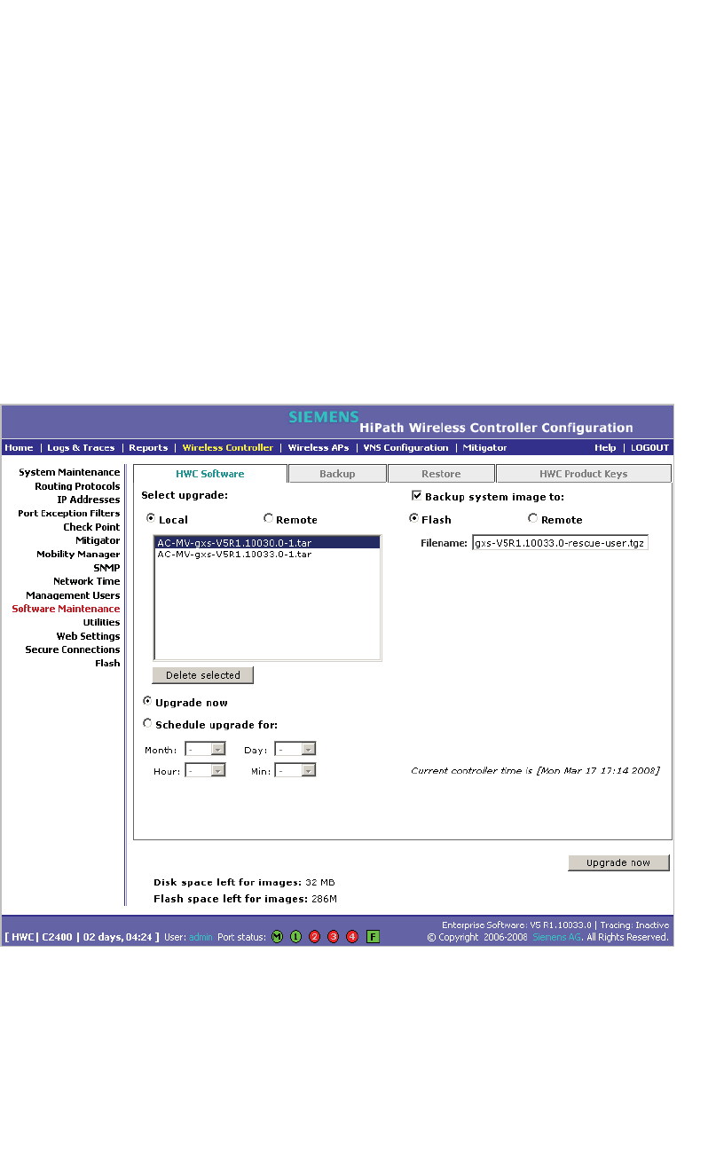
Performing system maintenance
hwc_ongoing.fm
Performing HiPath Wireless Controller software maintenance
A31003-W1050-U100-2-7619,March 2008
330 HiPath Wireless Controller, Access Points and Convergence Software V5 R1 , C20/C2400 User Guide
a) Click the Upgrade now button.
b) Review the upgrade settings in the dialog box that is displayed. If
correct, click OK to confirm the upgrade. Once you confirm the
upgrade, all sessions are closed. The Software maintenance window
is displayed, providing the status of the upgrade. The previous
software is uninstalled automatically. The new software is installed.
The HiPath Wireless Controller reboots automatically. The database
is updated and migrated.
To perform a remote upgrade of HiPath Wireless Controller software using
a downloaded image file from an the FTP server:
1. From the main menu, click Wireless Controller Configuration. The
Wireless Controller Configuration page is displayed.
2. From the left pane, click Software Maintenance. The HWC Software tab is
displayed.
3. Select Remote, and then type the following:
• FTP Server – The IP address of the FTP server to retrieve the image file
from.
• User ID – The user ID used to log in to the FTP server.
• Password – The corresponding password for the user ID.

hwc_ongoing.fm
Performing system maintenance
Performing HiPath Wireless Controller software maintenance
A31003-W1050-U100-2-7619, March 2008
HiPath Wireless Controller, Access Points and Convergence Software V5 R1 , C20/C2400 User Guide 331
• Confirm – The corresponding password for the user ID, to confirm it was
typed correctly.
•Directory – The directory on the server in which the image file that is to
be retrieved is stored.
• Filename – The name of the image file to retrieve.
• Destination – Select the location where the image file is to be saved:
•Flash – The image file will be saved on the flash memory card.
• Local – The image file will be saved on the HiPath Wireless
Controller.
4. Click Get Image now. The FTP Image window is displayed, providing the
status and results of the FTP upload. The image is uploaded onto your
system and added to the Select upgrade list.
5. In the Select upgrade list, click the image file you want to upgrade to.
6. If applicable, backup the current system image:
•To save the backup image locally, select the Flash option, and then type
a file name for the backup image in the Filename box. The filename must
end with the .tgz extension.
•To save the backup image on a remote FTP server, select the Remote
option, and then type the following:
• FTP Server – The IP address of the FTP server that will store the
image file.
• User ID – The user ID used to log in to the FTP server.
• Password – The corresponding password for the user ID.
• Confirm – The corresponding password for the user ID, to confirm it
was typed correctly.
•Directory – The directory on the server in which the image file is to
be stored.
•Filename – The name of the image file. The filename must end with
the .tgz extension.
7. If applicable, clear the Backup system image to option if you do not want to
save a backup image of your current system.
Caution: You should always backup your current system during the upgrade
process. Having a backup image of your system provides you the option of
restoring your system to its previous configuration, if needed.

Performing system maintenance
hwc_ongoing.fm
Performing HiPath Wireless Controller software maintenance
A31003-W1050-U100-2-7619,March 2008
332 HiPath Wireless Controller, Access Points and Convergence Software V5 R1 , C20/C2400 User Guide
8. Do one of the following:
•To schedule a backup, select the Schedule upgrade for option.
a) Use the Month,Day,Hour, and Minute drop-down lists to schedule
the upgrade.
b) Click Schedule upgrade.
c) Review the upgrade settings in the dialog box that is displayed. If
correct, click OK to confirm the upgrade. Once you confirm the
upgrade, the HWC Software tab fields become grayed out.
Note: A scheduled upgrade is not a recurring event. The HiPath Wireless
Controller only allows one scheduled upgrade to be scheduled at a time.
•To perform the upgrade now, select the Upgrade now option.
a) Click the Upgrade now button.
b) Review the upgrade settings in the dialog box that is displayed. If
correct, click OK to confirm the upgrade. Once you confirm the
upgrade, all sessions are closed. The Software maintenance window
is displayed, providing the status of the upgrade. The previous
software is uninstalled automatically. The new software is installed.
The HiPath Wireless Controller reboots automatically. The database
is updated and migrated.
11.4.2.2 Modifying a scheduled software upgrade
To modify a schedule software upgrade, you first need to cancel the existing
schedule upgraded, and then reschedule a new software upgrade.
To modify a schedule software upgrade:
1. From the main menu, click Wireless Controller Configuration. The
Wireless Controller Configuration page is displayed.
2. From the left pane, click Software Maintenance. The HWC Software tab is
displayed.
3. Click Cancel upgrade.
4. In the dialog box that is displayed, click OK to confirm the cancellation of the
upgrade. The scheduled software upgrade is cancelled and the HWC
Software tab fields become available for scheduling a new software upgrade.
For more information, see Section 11.4.2, “Upgrading HiPath Wireless
Controller software”, on page 324.

hwc_ongoing.fm
Performing system maintenance
Performing HiPath Wireless Controller software maintenance
A31003-W1050-U100-2-7619, March 2008
HiPath Wireless Controller, Access Points and Convergence Software V5 R1 , C20/C2400 User Guide 333
11.4.2.3 Deleting a software image
You can delete a software image if it is no longer needed on your system.
To delete a software upgrade:
1. From the main menu, click Wireless Controller Configuration. The
Wireless Controller Configuration page is displayed.
2. From the left pane, click Software Maintenance. The HWC Software tab is
displayed.
3. In the Select upgrade list, click the software upgrade you want to delete.
4. Click Delete selected.
5. In the dialog box that is displayed, click OK to confirm the deletion of the
upgrade. The Software Maintenance window is displayed, providing the
status and results of the deletion.
11.4.3 Backing up the HiPath Wireless Controller
database
When you backup the HiPath Wireless Controller database, you can choose to
do the following:
•Backup the HiPath Wireless Controller database now
•Upload a backup to an FTP server
•Schedule when a backup occurs
•Schedule a backup and copy it to an FTP server
To back up the HiPath Wireless Controller database now:
1. From the main menu, click Wireless Controller Configuration. The
Wireless Controller Configuration page is displayed.
2. From the left pane, click Software Maintenance. The HWC Software tab is
displayed.
3. Click the Backup tab.
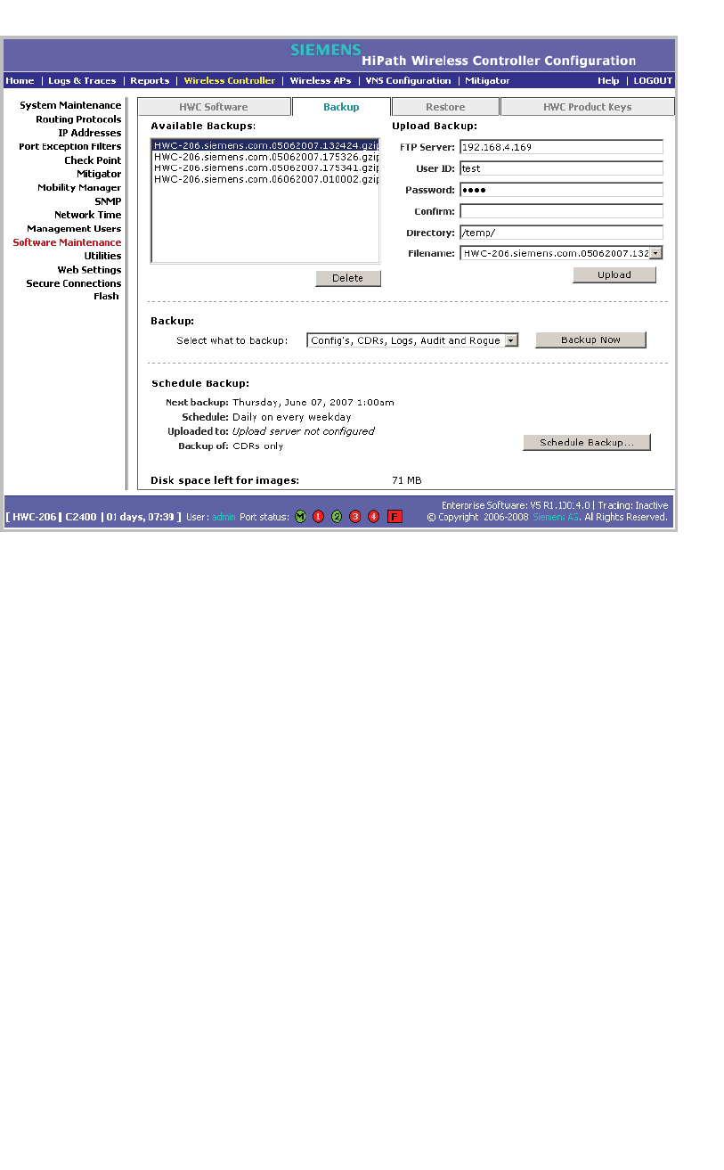
Performing system maintenance
hwc_ongoing.fm
Performing HiPath Wireless Controller software maintenance
A31003-W1050-U100-2-7619,March 2008
334 HiPath Wireless Controller, Access Points and Convergence Software V5 R1 , C20/C2400 User Guide
The Available Backups list displays items that have already been backed up
and are available.
4. In the Backup section, click an item from the Select what to backup
drop-down list.
5. To launch the backup of the selected items, click Backup Now. The Software
Maintenance window is displayed, providing the status and results of the
backup.
11.4.3.1 Uploading a backup to an FTP server
You can upload an existing backup file to an FTP server. When an existing
backup is uploaded to an FTP server, the uploaded backup file is removed from
the Available Backups list.
To upload an existing backup to an FTP server:
1. From the main menu, click Wireless Controller Configuration. The
Wireless Controller Configuration page is displayed.
2. From the left pane, click Software Maintenance. The HWC Software tab is
displayed.
3. Click the Backup tab.

hwc_ongoing.fm
Performing system maintenance
Performing HiPath Wireless Controller software maintenance
A31003-W1050-U100-2-7619, March 2008
HiPath Wireless Controller, Access Points and Convergence Software V5 R1 , C20/C2400 User Guide 335
4. To upload a backup, type the following:
•FTP Server – The IP of the FTP server to where the backup will be copied
to.
•User ID – The user ID used to log in to the FTP server.
• Password – The corresponding password for the user ID.
• Confirm – The corresponding password for the user ID to confirm it was
typed correctly.
•Directory – The directory on the server where the image file will be
stored.
5. In the Filename drop-down list, click the backup you want to upload.
6. Click Upload. The Software Maintenance window is displayed, providing
the status and results of the backup.
11.4.3.2 Scheduling a backup
When you schedule a backup, you can either chose to save the back to an FTP
server or have the scheduled backup saved on your system.
Note: If you do not specify an FTP server in the Schedule Backups window
when you define the backup schedule, the backup is added to the Available
Backups list on the Backup tab.
To schedule a backup:
1. From the main menu, click Wireless Controller Configuration. The
Wireless Controller Configuration page is displayed.
2. From the left pane, click Software Maintenance. The HWC Software tab is
displayed.
3. Click the Backup tab.
4. Click Schedule Backup. The Schedule Backups page is displayed.
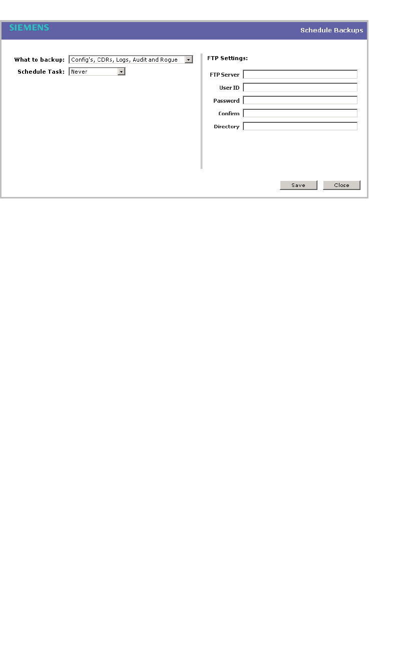
Performing system maintenance
hwc_ongoing.fm
Performing HiPath Wireless Controller software maintenance
A31003-W1050-U100-2-7619,March 2008
336 HiPath Wireless Controller, Access Points and Convergence Software V5 R1 , C20/C2400 User Guide
5. In the What to backup drop-down list, click what you want to backup:
•Config’s, CDRs, Logs, Audit and Rogue
•Configurations only
•CDRs only
•Logs only
•Audit only
•Rogue only
6. In the Schedule task drop-down list, click the frequency of the backup:
•Daily – Click the Start Time and Recurrence for the backup.
• Weekly – Click the Start Time and Recurrence for the backup.
•Monthly – Click the Start Time and Recurrence for the backup.
• Never – Click to make the scheduled backup a one-time event.
7. If applicable, specify an FTP server to where the scheduled backup will be
copied to. In the FTP settings section, type the following:
•FTP Server – The IP of the FTP server to where the scheduled
backup will be copied to.
•User ID – The user ID used to log in to the FTP server.
• Password – The corresponding password for the user ID.
•Confirm – The corresponding password for the user ID to confirm it
was typed correctly.
•Directory – The directory on the server where the image file will be
stored.

hwc_ongoing.fm
Performing system maintenance
Performing HiPath Wireless Controller software maintenance
A31003-W1050-U100-2-7619, March 2008
HiPath Wireless Controller, Access Points and Convergence Software V5 R1 , C20/C2400 User Guide 337
8. To save your changes, click Save.
11.4.3.3 Deleting a backup
You can delete a backup if it is no longer needed on your system.
To delete a backup:
1. From the main menu, click Wireless Controller Configuration. The
Wireless Controller Configuration page is displayed.
2. From the left pane, click Software Maintenance. The HWC Software tab is
displayed.
3. Click the Backup tab.
4. In the Available Backups list, click the backup you want to delete.
5. Click Delete.
6. In the dialog box that is displayed, click OK to confirm the deletion. The
Software Maintenance window is displayed, providing the status and results
of the deletion.
11.4.4 Restoring the HiPath Wireless Controller
database
When you restore the HiPath Wireless Controller database, you can choose to
download a backup from an FTP server for a restore.
To restore the HiPath Wireless Controller software:
1. From the main menu, click Wireless Controller Configuration. The
Wireless Controller Configuration page is displayed.
2. From the left pane, click Software Maintenance. The HWC Software tab is
displayed.
3. Click the Restore tab.
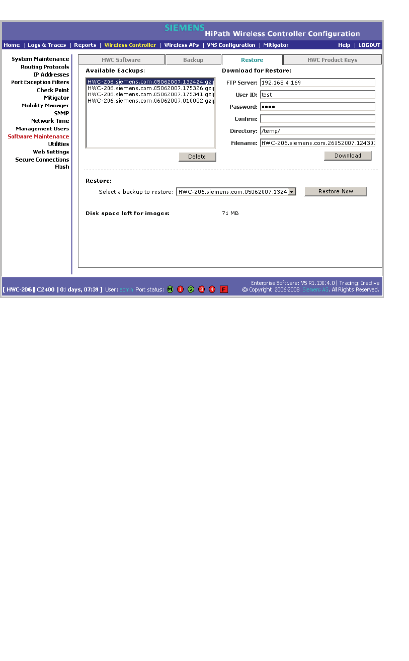
Performing system maintenance
hwc_ongoing.fm
Performing HiPath Wireless Controller software maintenance
A31003-W1050-U100-2-7619,March 2008
338 HiPath Wireless Controller, Access Points and Convergence Software V5 R1 , C20/C2400 User Guide
The Available Backups list displays items that have already been backed up
and are available.
4. In the Restore section, click the backup configuration you want to restore
from the Select a backup to restore drop-down list.
5. To restore the backup configuration, click Restore Now.
6. Review the restore settings in the dialog box that is displayed. If correct, click
OK to confirm the restore. The Software Maintenance window is displayed,
providing the status and results of the restore.
7. Reboot your system. For more information, see Section 11.3, “Performing
system maintenance tasks”, on page 317.
To download a backup from an FTP server for a restore:
1. From the main menu, click Wireless Controller Configuration. The
Wireless Controller Configuration page is displayed.
2. From the left pane, click Software Maintenance. The System Maintenance
page is displayed.
3. Click the Restore tab.
4. To download a backup for a restore, type the following:
• FTP Server –The FTP server to retrieve the backup file from.

hwc_ongoing.fm
Performing system maintenance
Performing HiPath Wireless Controller software maintenance
A31003-W1050-U100-2-7619, March 2008
HiPath Wireless Controller, Access Points and Convergence Software V5 R1 , C20/C2400 User Guide 339
•User ID – The user ID used to log in to the FTP server.
• Password – The corresponding password for the user ID.
• Confirm – The corresponding password for the user ID to confirm it was
typed correctly.
•Directory – The directory on the server in which the backup file that is to
be retrieved is stored.
• Filename – The name of the image file to retrieve.
5. Click Download. The backup is downloaded and added to the Available
Backups list.
To delete a backup available for restore:
1. From the main menu, click Wireless Controller Configuration. The
Wireless Controller Configuration page is displayed.
2. From the left pane, click Software Maintenance. The System Maintenance
page is displayed.
3. Click the Restore tab.
4. To delete a backup from the list, click the backup in the Available Backups
list you want to delete.
5. Click Delete.
6. Review the restore settings in the dialog box that is displayed. If correct, click
OK to confirm the deletion. The Software Maintenance window is displayed,
providing the status and results of the deletion.
11.4.5 Upgrading a HiPath Wireless Controller using
SFTP
You can upload an image file to the HiPath Wireless Controller using Secure FTP
(SFTP). The HiPath Wireless Controller supports any SFTP client.
Note: You must enable management traffic before you try to connect with a SFTP
client. Specify the exact image path for the corresponding SW package (see
directory information below). Otherwise, the HiPath Wireless Controller cannot
locate them for SW upgrades/updates.
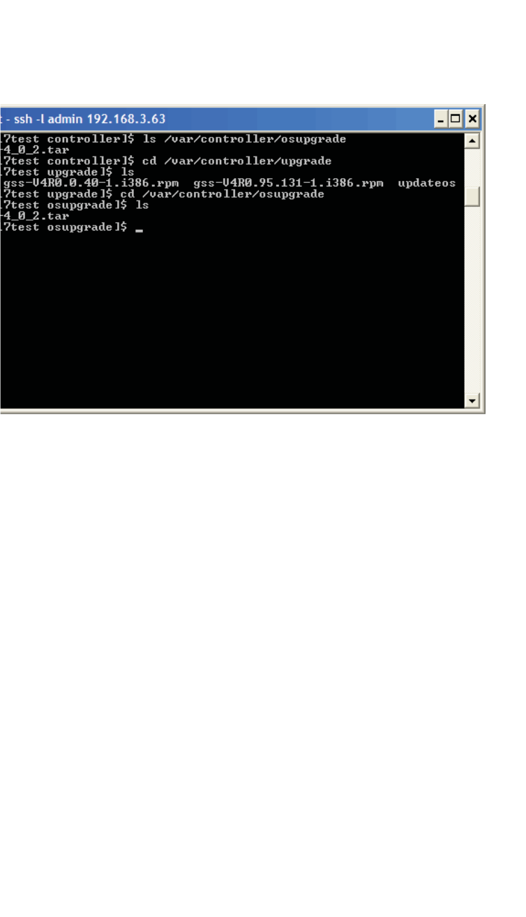
Performing system maintenance
hwc_ongoing.fm
Performing HiPath Wireless Controller software maintenance
A31003-W1050-U100-2-7619,March 2008
340 HiPath Wireless Controller, Access Points and Convergence Software V5 R1 , C20/C2400 User Guide
To upload an image file:
1. Launch the SFTP client, point it to the HiPath Wireless Controller and login
in. The exact details of how to do this will depend on the client used. The
following uses putty as an example:
2. Change to the directory to receive the uploaded file:
•For AP images change to: /var/controller/images/ap/
•For HiPath Wireless Controller images change to: /var/controller/upgrade
•For OS archives change to: /var/controller/osupgrade
3. Upload the image file using the SFTP client upload feature.
4. To complete a HiPath Wireless Controller upgrade or an AP upgrade go to the
appropriate Software Maintenance page. For more information, see Section
11.4.2, “Upgrading HiPath Wireless Controller software”, on page 324.
11.4.6 Maintaining the HiPath Wireless Controller
product license keys
Software maintenance also includes the product key maintenance for first time
setup and upgrades. For more information, see Section 3.2.3, “Applying the
product license key”, on page 41.
mp
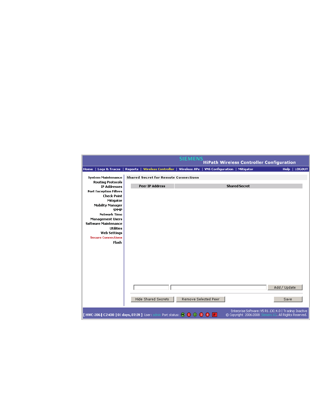
hwc_ongoing.fm
Performing system maintenance
Performing HiPath Wireless Controller software maintenance
A31003-W1050-U100-2-7619, March 2008
HiPath Wireless Controller, Access Points and Convergence Software V5 R1 , C20/C2400 User Guide 341
11.4.7 Configuring the HiPath Wireless Controller for
interaction with the HiPath Wireless Manager
The HiPath Wireless Manager application provides administrators with a
graphical overview of the entire HiPath wireless network, including real time
wireless event monitoring. You must configure each HiPath Wireless Controller in
order to interact with the HiPath Wireless Manager. To configure the HiPath
Wireless Controller to interact with the HiPath Wireless Manager, a shared secret
must be defined for both. For more information, see the HiPath Wireless Manager
User Guide.
To configure a shared secret for interaction with the HiPath Wireless
Manager:
1. From the main menu, click Wireless Controller Configuration. The
Wireless Controller Configuration page is displayed.
2. From the left pane, click Secure Connections. The Shared Secret for
Remote Connections page is displayed.
3. In the first box, type the controller’s IP address.
4. In the second box, type the shared secret to be used by both the HiPath
Wireless Controller and the HiPath Wireless Manager. The shared secret can
be a maximum of 16 (232 ASCII) characters. Each IP connection can have a
different secret.

Performing system maintenance
hwc_ongoing.fm
Working with system logs, trace messages, and audits
A31003-W1050-U100-2-7619,March 2008
342 HiPath Wireless Controller, Access Points and Convergence Software V5 R1 , C20/C2400 User Guide
5. Click Add/Update. The table is updated with the IP address and shared
secret.
6. To hide the shared secrets, click Hide Shared Secrets. To show the shared
secrets, click Show Shared Secrets.
7. To remove a connections, click the IP address in the table and then click
Remove Selected Peer.
8. To save your changes, click Save.
11.5 Working with system logs, trace messages, and audits
The system stores configuration data and log files. These files include:
•event and alarm logs (triggered by events)
•trace messagess (triggered by component activity)
•User interface audit messages
•DHCP messages
•accounting files (created every 30 minutes, to a maximum of six files)
The files are stored in the operating system and have a maximum size of one GB.
The accounting files are stored in flat files in a directory that is created every day.
Eight directories are maintained in a circular buffer — when all are full, the most
recent replaces the earliest.
11.5.1 Logs, traces, audits, and DHCP messages
The HiPath Wireless Controller generates four types of messages:
• Logs (including alarms) – Messages that are triggered by events
•Traces – Messages that display activity by component, for system
debugging, troubleshooting, and internal monitoring of software
Caution: In order for the Debug Info option on the Wireless AP Traces page
to return trace messages, this option must enabled while Wireless AP debug
commands are running. To do so, you need to run a Wireless AP CLI
command to turn on a specific Wireless AP debug. Once the CLI command
is run, select the Debug Info option, and then click Retrieve Traces. For
more information, see the HiPath Wireless Controller, Access Points and
Convergence Software CLI Reference Guide.

hwc_ongoing.fm
Performing system maintenance
Working with system logs, trace messages, and audits
A31003-W1050-U100-2-7619, March 2008
HiPath Wireless Controller, Access Points and Convergence Software V5 R1 , C20/C2400 User Guide 343
Because Wireless AP debugging can affect the normal operation of Wireless
AP service, enabling debugging is not recommended unless specific
instructions are provided.
• Audits – Messages that record administrative changes made to the system
•DHCP – Messages that record DHCP service events
11.5.1.1 Working with logs
The log messages contain the time of event, severity, source component, and any
details generated by the source component. Log messages are divided into two
groups:
•HiPath Wireless Controller logs
•Wireless AP logs
Log severity levels
Log messages are classified at four levels of severity:
•Information (the activity of normal operation)
•Minor (alarm)
•Major (alarm)
•Critical (alarm)
The alarm messages (minor, major or critical log messages) are triggered by
activities that meet certain conditions that should be known and dealt with. The
following are examples of events on the HiPath Wireless Controller that generate
an alarm message:
•Reboot due to failure
•Software upgrade failure on the HiPath Wireless Controller
•Software upgrade failure on the Wireless AP
•Detection of rogue access point activity without valid ID
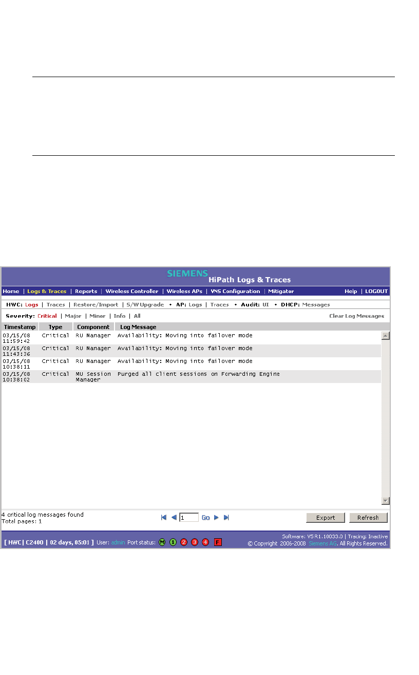
Performing system maintenance
hwc_ongoing.fm
Working with system logs, trace messages, and audits
A31003-W1050-U100-2-7619,March 2008
344 HiPath Wireless Controller, Access Points and Convergence Software V5 R1 , C20/C2400 User Guide
If SNMP is enabled on the HiPath Wireless Controller, alarm conditions will
trigger a trap in SNMP (Simple Network Management Protocol). An SNMP trap is
an event notification sent by the managed agent (a network device) to the
management system to identify the occurrence of conditions.
Note: The log statements Low water mark level was reached and Incoming
message dropped, because of the rate limiting mechanism indicate that
there is a burst of log messages coming to the event server and the processing
speed is slower than the incoming rate of log messages. These messages do not
indicate that the system is impaired in any way.
To view HiPath Wireless Controller logs:
1. From the main menu, click Logs & Traces. The Logs & Traces page is
displayed.
2. Click the HWC: Logs tab. The HiPath Wireless Controller log page is
displayed and the events are displayed in chronological order:
3. To sort the events by Timestamp, Type, or Component, click the appropriate
column heading.
4. To filter the events by severity, Critical,Major,Minor,Info, and All, click the
appropriate log severity.
5. To refresh the HiPath Wireless Controller log page, click Refresh.
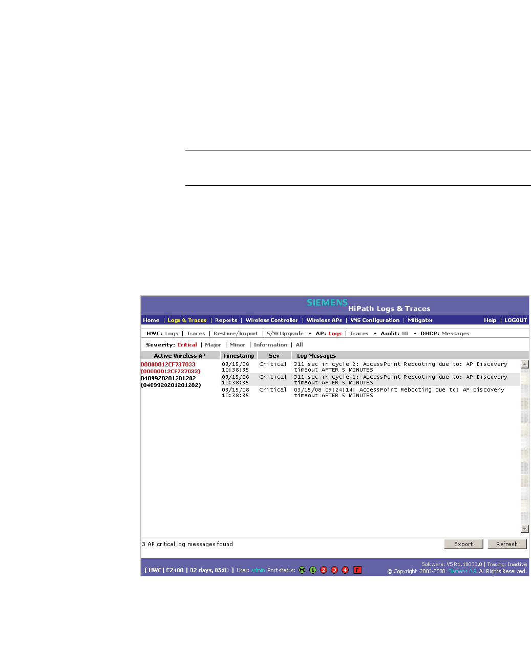
hwc_ongoing.fm
Performing system maintenance
Working with system logs, trace messages, and audits
A31003-W1050-U100-2-7619, March 2008
HiPath Wireless Controller, Access Points and Convergence Software V5 R1 , C20/C2400 User Guide 345
6. To export the HiPath Wireless Controller log page, click Export. The File
Download dialog is displayed.
7. Do one of the following:
•To open the log file, click Open.
•To save the log file, click Save, and then navigate to the directory location
you want to save the file.
•Click Save.
Note: The component "Langley" is the term for the inter-process messaging
infrastructure on the HiPath Wireless Controller.
To view Wireless AP logs:
1. From the main menu, click Logs & Traces. The Logs & Traces page is
displayed.
2. Click the AP: Logs tab. The Wireless AP log page is displayed and the events
are displayed in chronological order:
3. In the Active Wireless AP list, click a Wireless AP to view the log events for
that particular Wireless AP.
4. To sort the events by Timestamp or Severity, click the appropriate column
heading.
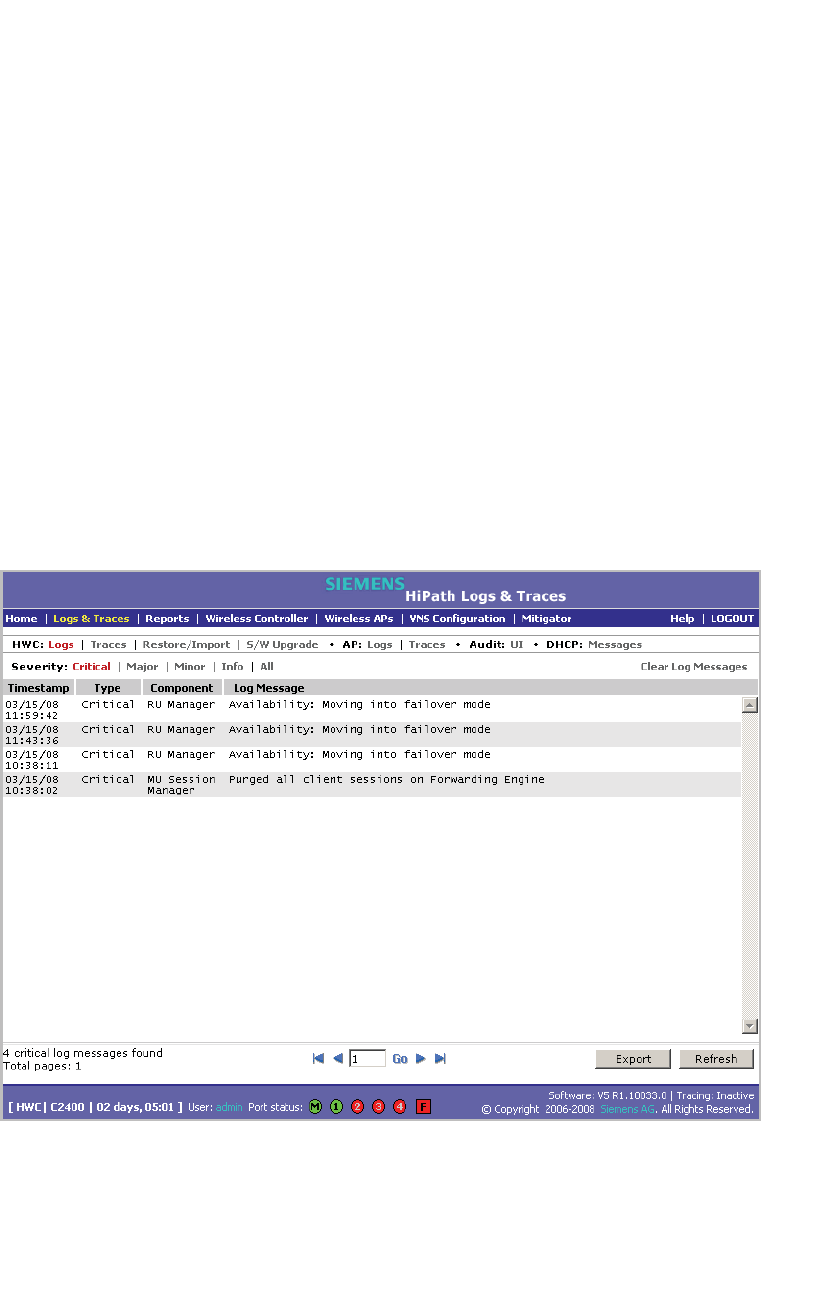
Performing system maintenance
hwc_ongoing.fm
Working with system logs, trace messages, and audits
A31003-W1050-U100-2-7619,March 2008
346 HiPath Wireless Controller, Access Points and Convergence Software V5 R1 , C20/C2400 User Guide
5. To filter the events by severity, Critical,Major,Minor,Info, and All, click the
appropriate log severity.
6. To refresh the HiPath Wireless Controller log page, click Refresh.
7. To export the HiPath Wireless Controller log page, click Export. The File
Download dialog is displayed.
8. Do one of the following:
•To open the log file, click Open.
•To save the log file, click Save, and then navigate to the directory location
you want to save the file.
•Click Save.
To clear HiPath Wireless Controller logs:
1. From the main menu, click Logs & Traces. The Logs & Traces page is
displayed.
2. Click the HWC: Logs tab. The HiPath Wireless Controller log page is
displayed and the events are displayed in chronological order:
3. To clear the logs, click Clear Log Messages.
4. To confirm the deletion of the HiPath Wireless Controller log messages, click
Ok. The HiPath Wireless Controller log messages are deleted.
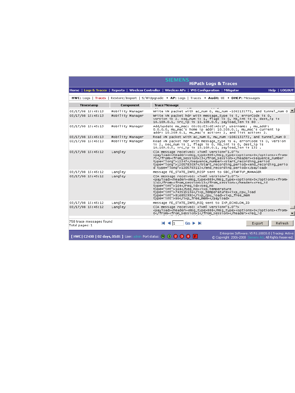
hwc_ongoing.fm
Performing system maintenance
Working with system logs, trace messages, and audits
A31003-W1050-U100-2-7619, March 2008
HiPath Wireless Controller, Access Points and Convergence Software V5 R1 , C20/C2400 User Guide 347
11.5.1.2 Working with trace messages
To view HiPath Wireless Controller traces:
1. From the main menu, click Logs & Traces. The Logs & Traces page is
displayed.
2. Click the HWC: Traces tab. The HiPath Wireless Controller trace page is
displayed and the events are displayed in chronological order:
3. To sort the events by Timestamp or Component, click the appropriate
column heading.
4. To refresh the HiPath Wireless Controller trace page, click Refresh.
5. To export the HiPath Wireless Controller trace page, click Export. The File
Download dialog is displayed.
6. Do one of the following:
•To open the trace file, click Open.
•To save the trace file, click Save, and then navigate to the directory
location you want to save the file.
•Click Save.
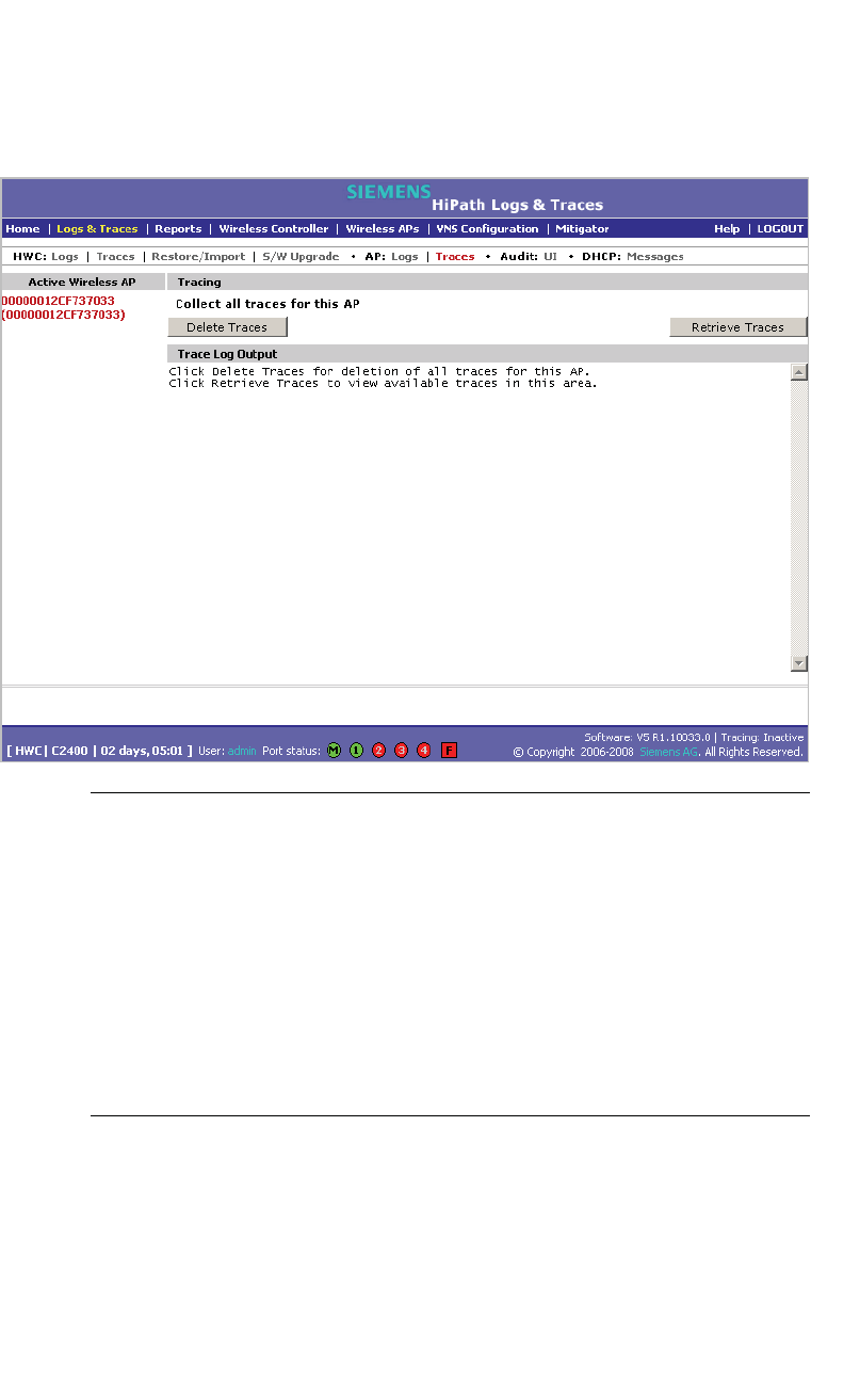
Performing system maintenance
hwc_ongoing.fm
Working with system logs, trace messages, and audits
A31003-W1050-U100-2-7619,March 2008
348 HiPath Wireless Controller, Access Points and Convergence Software V5 R1 , C20/C2400 User Guide
To view Wireless AP traces:
1. From the main menu, click Logs & Traces. The Logs & Traces page is
displayed.
2. Click the AP: Traces tab. The Wireless AP trace page is displayed.
Caution: In order for the Debug Info option on the Wireless AP Traces page
to return trace messages, this option must enabled while Wireless AP debug
commands are running. To do so, you need to run a Wireless AP CLI
command to turn on a specific Wireless AP debug. Once the CLI command
is run, select the Debug Info option, and then click Retrieve Traces. For
more information, see the HiPath Wireless Controller, Access Points and
Convergence Software CLI Reference Guide.
Because Wireless AP debugging can affect the normal operation of Wireless
AP service, enabling debugging is not recommended unless specific
instructions are provided.
3. In the Active Wireless AP list, click the Wireless 802.11n AP whose trace
messages you want to view.
4. In the Collect traces for section, do the following:
• Configurations – Select to collect trace configuration information.

hwc_ongoing.fm
Performing system maintenance
Working with system logs, trace messages, and audits
A31003-W1050-U100-2-7619, March 2008
HiPath Wireless Controller, Access Points and Convergence Software V5 R1 , C20/C2400 User Guide 349
• Start/Stop Tracing – Click to start or stop the collection of traces for
this Wireless AP.
• Retrieve Traces – Click to view the available configuration traces in
the Trace Log Output section.
• Debug info – Select to collect trace debug information for this Wireless
AP.
• Start/Stop Tracing – Click to start or stop the collection of traces for
this Wireless AP.
• Retrieve Traces – Click to view the available debug traces in the
Trace Log Output section.
•Reports – Select to view available crash files.
• Retrieve Traces – Click to view available crash files in the Trace Log
Output section.
• Delete all crash reports – Click to delete all crash reports for this
Wireless AP.
5. To refresh the HiPath Wireless Controller trace page, click Refresh.
6. To export and view the Wireless AP trace page in HTML format, click Export.
Working with Wireless 802.11n AP traces
Wireless 802.11n AP traces are combined into a single .tar.gz file and can only
be viewed by saving the tar.gz file to a directory on your computer.
To view Wireless 802.11n AP traces:
1. From the main menu, click Logs & Traces. The Logs & Traces page is
displayed.
2. Click the AP Traces tab. The Wireless AP trace page is displayed.
3. In the Active Wireless AP list, click the Wireless 802.11n AP whose trace
messages you want to view.
4. Click Retrieve Traces. The File Download dialog appears.
5. Click Save and navigate to the location on your computer that you want to
save the Wireless 802.11n AP trace report. The file is saved as a .tar.gz file.
6. To view the file, unzip the .tar.gz file.
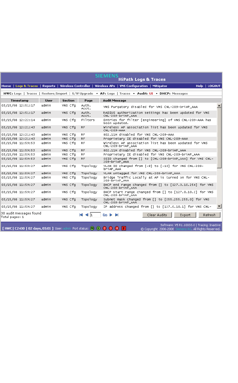
Performing system maintenance
hwc_ongoing.fm
Working with system logs, trace messages, and audits
A31003-W1050-U100-2-7619,March 2008
350 HiPath Wireless Controller, Access Points and Convergence Software V5 R1 , C20/C2400 User Guide
11.5.1.3 Working with audit messages
To view audits:
1. From the main menu, click Logs & Traces. The Logs & Traces page is
displayed.
2. Click the Audit: UI tab. The audit page is displayed and the events are
displayed in chronological order.
3. To sort the events by Timestamp, User, Section, or Page, click the
appropriate column heading.
4. To refresh the audit page, click Refresh.
5. To export the audit page, click Export. The File Download dialog is
displayed.
6. Do one of the following:
•To open the audit file, click Open.
•To save the audit file, click Save, and then navigate to the directory
location you want to save the file.
•Click Save.
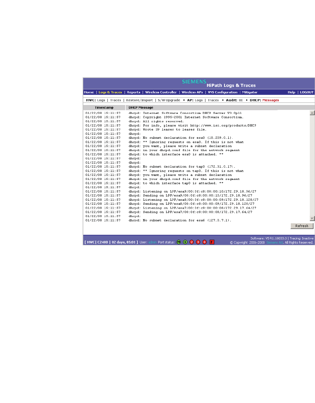
hwc_ongoing.fm
Performing system maintenance
Working with system logs, trace messages, and audits
A31003-W1050-U100-2-7619, March 2008
HiPath Wireless Controller, Access Points and Convergence Software V5 R1 , C20/C2400 User Guide 351
11.5.1.4 Working with DHCP messages
To view DHCP messages:
1. From the main menu, click Logs & Traces. The Logs & Traces page is
displayed.
2. Click the DHCP: Messages tab. The DHCP message page is displayed and
the events are displayed in chronological order.
3. To sort the events by timestamp, click Timestamp.
4. To refresh the DHCP message page, click Refresh.
11.5.1.5 Working with software upgrade messages
The S/W Upgrade tab displays the most recent upgrade actions, either success
or failure. Some examples of the actions that can be dispayed are:
•FTP failure during backup system image
•Database reset failure
•Database export failure
•Database import details
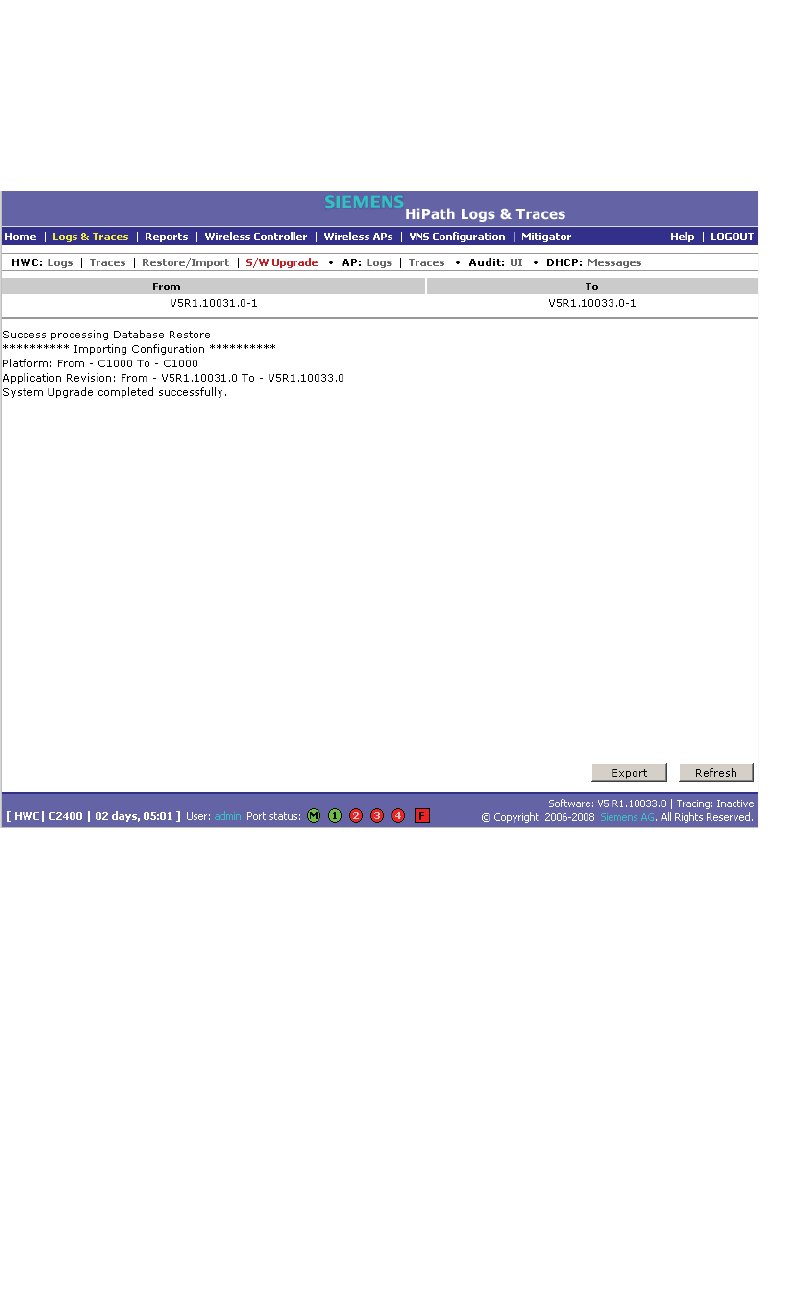
Performing system maintenance
hwc_ongoing.fm
Working with system logs, trace messages, and audits
A31003-W1050-U100-2-7619,March 2008
352 HiPath Wireless Controller, Access Points and Convergence Software V5 R1 , C20/C2400 User Guide
To view software upgrade messages:
1. From the main menu, click Logs & Traces. The Logs & Traces page is
displayed.
2. Click the S/W Upgrade tab. The software upgrade message page is
displayed.
3. To refresh the software upgrade message page, click Refresh.
4. To export the software upgrade message page, click Export. The File
Download dialog is displayed.
5. Do one of the following:
•To open the file, click Open.
•To save the file, click Save, and then navigate to the directory location you
want to save the file.
•Click Save.
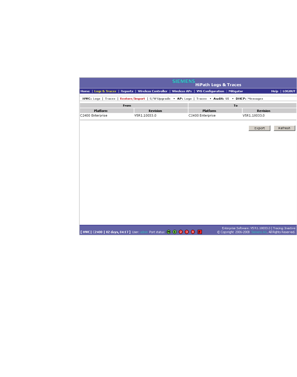
hwc_ongoing.fm
Performing system maintenance
Working with system logs, trace messages, and audits
A31003-W1050-U100-2-7619, March 2008
HiPath Wireless Controller, Access Points and Convergence Software V5 R1 , C20/C2400 User Guide 353
11.5.1.6 Working with restore/import messages
The Restore/Import tab displays the most recent restore/import results.
To view restore/import messages:
1. From the main menu, click Logs & Traces. The Logs & Traces page is
displayed.
2. Click the Restore/Import tab. The restore/import message page is displayed.
3. To refresh the restore/import message page, click Refresh.
4. To export the restore/import message page, click Export. The File Download
dialog is displayed.
5. Do one of the following:
•To open the file, click Open.
•To save the file, click Save, and then navigate to the directory location you
want to save the file.
•Click Save.

Performing system maintenance
hwc_ongoing.fm
Working with system logs, trace messages, and audits
A31003-W1050-U100-2-7619,March 2008
354 HiPath Wireless Controller, Access Points and Convergence Software V5 R1 , C20/C2400 User Guide

hwc_glossary.fm
A31003-W1050-U100-2-7619, March 2008
HiPath Wireless Controller, Access Points and Convergence Software V5 R1 , C20/C2400 User Guide 355
Glossary
Networking terms and abbreviations
12 Glossary
12.1 Networking terms and abbreviations
Term Explanation
AAA Authentication, Authorization and Accounting. A system in IP-based networking to control
what computer resources users have access to and to keep track of the activity of users over
a network.
Access Point (AP) A wireless LAN transceiver or "base station" that can connect a wired LAN to one or many
wireless devices.
Ad-hoc mode An 802.11 networking framework in which devices or stations communicate directly with each
other, without the use of an access point (AP). (Compare Infrastructure Mode)
AES Advanced Encryption Standard (AES) is an algorithm for encryption that works at multiple
network layers simultaneously. As a block cipher, AES encrypts data in fixed-size blocks of
128 bits. AES was created by the National Institute of Standards and Technology (NIST). AES
is a privacy transform for IPSec and Internet Key Exchange (IKE). AES has a variable key
length - the algorithm can specify a 128-bit key (the default), a 192-bit key, or a 256-bit key.
For the WPA2/802.11i implementation of AES, a 128 bit key length is used. AES encryption
includes 4 stages that make up one round. Each round is then iterated 10, 12 or 14 times
depending upon the bit-key size. For the WPA2/802.11i implementation of AES, each round
is iterated 10 times.
AES-CCMP AES uses the Counter-Mode/CBC-MAC Protocol (CCMP). CCM is a new mode of operation
for a block cipher that enables a single key to be used for both encryption and authentication.
The two underlying modes employed in CCM include Counter mode (CTR) that achieves data
encryption and Cipher Block Chaining Message Authentication Code (CBC-MAC) to provide
data integrity.
ARP Address Resolution Protocol. A protocol used to obtain the physical addresses (such as MAC
addresses) of hardware units in a network environment. A host obtains such a physical
address by broadcasting an ARP request, which contains the IP address of the target
hardware unit. If the request finds a unit with that IP address, the unit replies with its physical
hardware address.
Association A connection between a wireless device and an Access Point.
asynchronous Asynchronous transmission mode (ATM). A start/stop transmission in which each character is
preceded by a start signal and followed by one or more stop signals. A variable time interval
can exist between characters. ATM is the preferred technology for the transfer of images.
BSS Basic Service Set. A wireless topology consisting of one Access Point connected to a wired
network and a set of wireless devices. Also called an infrastructure network. See also IBSS.
Captive Portal A browser-based authentication mechanism that forces unauthenticated users to a Web page.
Sometimes called a "reverse firewall".
Table 29

Glossary
hwc_glossary.fm
Networking terms and abbreviations
A31003-W1050-U100-2-7619,March 2008
356 HiPath Wireless Controller, Access Points and Convergence Software V5 R1 , C20/C2400 User Guide
CDR Call Data (Detail) Record
In Internet telephony, a call detail record is a data record that contains information related to
a telephone call, such as the origination and destination addresses of the call, the time the call
started and ended, the duration of the call, the time of day the call was made and any toll
charges that were added through the network or charges for operator services, among other
details of the call.
In essence, call accounting is a database application that processes call data from your switch
(PBX, iPBX, or key system) via a CDR (call detail record) or SMDR (station message detail
record) port. The call data record details your system's incoming and outgoing calls by
thresholds, including time of call, duration of call, dialing extension, and number dialed. Call
data is stored in a PC database
CHAP Challenge-Handshake Authentication Protocol. One of the two main authentication protocols
used to verify a user's name and password for PPP Internet connections. CHAP is more
secure than PAP because it performs a three-way handshake during the initial link
establishment between the home and remote machines. It can also repeat the authentication
anytime after the link has been established.
CLI Command Line Interface.
Collision Two Ethernet packets attempting to use the medium simultaneously. Ethernet is a shared
media, so there are rules for sending packets of data to avoid conflicts and protect data
integrity. When two nodes at different locations attempt to send data at the same time, a
collision will result. Segmenting the network with bridges or switches is one way of reducing
collisions in an overcrowded network.
Datagram A datagram is "a self-contained, independent entity of data carrying sufficient information to
be routed from the source to the destination computer without reliance on earlier exchanges
between this source and destination computer and the transporting network." (RFC1594). The
term has been generally replaced by the term packet. Datagrams or packets are the message
units that the Internet Protocol deals with and that the Internet transports.
Decapsulation See tunnelling.
Device Server A specialized, network-based hardware device designed to perform a single or specialized set
of server functions. Print servers, terminal servers, remote access servers and network time
servers are examples of device servers.
DHCP Dynamic Host Configuration Protocol. A protocol for assigning dynamic IP addresses to
devices on a network. With dynamic addressing, a device can have a different IP address
every time it connects to the network. In some systems, the device's IP address can even
change while it is still connected. DHCP also supports a mix of static and dynamic IP
addresses.
DHCP consists of two components: a protocol for delivering host-specific configuration
parameters from a DHCP server to a host and a mechanism for allocation of network
addresses to hosts. (IETF RFC1531.)
Option 78 specifies the location of one or more SLP Directory Agents. Option 79 specifies the
list of scopes that a SLP Agent is configured to use.(RFC2610 - DHCP Options for Service
Location Protocol)
Term Explanation
Table 29

hwc_glossary.fm
Glossary
Networking terms and abbreviations
A31003-W1050-U100-2-7619, March 2008
HiPath Wireless Controller, Access Points and Convergence Software V5 R1 , C20/C2400 User Guide 357
Directory Agent (DA) A method of organizing and locating the resources (such as printers, disk drives, databases,
e-mail directories, and schedulers) in a network. Using SLP, networking applications can
discover the existence, location and configuration of networked devices.
With Service Location Protocol, client applications are 'User Agents' and services are
advertised by 'Service Agents'. The User Agent issues a multicast 'Service Request' (SrvRqst)
on behalf of the client application, specifying the services required. The User Agent will
receive a Service Reply (SrvRply) specifying the location of all services in the network which
satisfy the request.
For larger networks, a third entity, called a 'Directory Agent', receives registrations from all
available Service Agents. A User Agent sends a unicast request for services to a Directory
Agent (if there is one) rather than to a Service Agent.
(SLP version 2, RFC2608, updating RFC2165)
Diversity antenna and
receiver
The AP has two antennae. Receive diversity refers to the ability of the AP to provide better
service to a device by receiving from the user on which ever of the two antennae is receiving
the cleanest signal. Transmit diversity refers to the ability of the AP to use its two antenna to
transmit on a specific antenna only, or on a alternate antennae. The antennae are called
diversity antennae because of this capability of the pair.
DNS Domain Name Server
DSSS Direct-Sequence Spread Spectrum. A transmission technology used in Local Area Wireless
Network (LAWN) transmissions where a data signal at the sending station is combined with a
higher data rate bit sequence, or chipping code, that divides the user data according to a
spreading ratio. The chipping code is a redundant bit pattern for each bit that is transmitted,
which increases the signal's resistance to interference. If one or more bits in the pattern are
damaged during transmission, the original data can be recovered due to the redundancy of
the transmission. (Compare FHSS)
DTIM DTIM delivery traffic indication message (in 802.11 standard)
Dynamic WEP The IEEE introduced the concept of user-based authentication using per-user encryption keys
to solve the scalability issues that surrounded static WEP. This resulted in the 802.1X
standard, which makes use of the IETF's Extensible Authentication Protocol (EAP), which was
originally designed for user authentication in dial-up networks. The 802.1X standard
supplemented the EAP protocol with a mechanism to send an encryption key to a Wireless
AP. These encryption keys are used as dynamic WEP keys, allowing traffic to each individual
user to be encrypted using a separate key.
EAP-TLS
EAP-TTLS
EAP-TLS Extensible Authentication Protocol - Transport Layer Security. A general protocol for
authentication that also supports multiple authentication methods, such as token cards,
Kerberos, one-time passwords, certificates, public key authentication and smart cards. IEEE
802.1x specifies how EAP should be encapsulated in LAN frames.
In wireless communications using EAP, a user requests connection to a WLAN through an
access point, which then requests the identity of the user and transmits that identity to an
authentication server such as RADIUS. The server asks the access point for proof of identity,
which the access point gets from the user and then sends back to the server to complete the
authentication.
EAP-TLS provides for certificate-based and mutual authentication of the client and the
network. It relies on client-side and server-side certificates to perform authentication and can
be used to dynamically generate user-based and session-based WEP keys.
EAP-TTLS (Tunneled Transport Layer Security) is an extension of EAP-TLS to provide
certificate-based, mutual authentication of the client and network through an encrypted tunnel,
as well as to generate dynamic, per-user, per-session WEP keys. Unlike EAP-TLS, EAP-
TTLS requires only server-side certificates.
(See also PEAP)
Term Explanation
Table 29

Glossary
hwc_glossary.fm
Networking terms and abbreviations
A31003-W1050-U100-2-7619,March 2008
358 HiPath Wireless Controller, Access Points and Convergence Software V5 R1 , C20/C2400 User Guide
ELA (OPSEC) Event Logging API (Application Program Interface) for OPSEC, a module in Check Point used
to enable third-party applications to log events into the Check Point VPN-1/FireWall-1
management system.
Encapsulation See tunnelling.
ESS Extended Service Set (ESS). Several Basic Service Sets (BSSs) can be joined together to
form one logical WLAN segment, referred to as an extended service set (ESS). The SSID is
used to identify the ESS. (See BSS and SSID.)
FHSS Frequency-Hopping Spread Spectrum. A transmission technology used in Local Area
Wireless Network (LAWN) transmissions where the data signal is modulated with a
narrowband carrier signal that "hops" in a random but predictable sequence from frequency
to frequency as a function of time over a wide band of frequencies. This technique reduces
interference. If synchronized properly, a single logical channel is maintained. (Compare
DSSS)
Fit, thin and fat APs A thin AP architecture uses two components: an access point that is essentially a stripped-
down radio and a centralized management controller that handles the other WLAN system
functions. Wired network switches are also required.
A fit AP, a variation of the thin AP, handles the RF and encryption, while the central
management controller, aware of the wireless users' identities and locations, handles secure
roaming, quality of service, and user authentication. The central management controller also
handles AP configuration and management.
A fat (or thick) AP architecture concentrates all the WLAN intelligence in the access point. The
AP handles the radio frequency (RF) communication, as well as authenticating users,
encrypting communications, secure roaming, WLAN management, and in some cases,
network routing.
FQDN Fully Qualified Domain Name. A "friendly" designation of a computer, of the general form
computer.[subnetwork.].organization.domain. The FQDN names must be translated into an IP
address in order for the resource to be found on a network, usually performed by a Domain
Name Server.
FTM Forwarding Table Manager
FTP File Transfer Protocol
Gateway In the wireless world, an access point with additional software capabilities such as providing
NAT and DHCP. Gateways may also provide VPN support, roaming, firewalls, various levels
of security, etc.
Gigabit Ethernet The high data rate of the Ethernet standard, supporting data rates of 1 gigabit (1,000
megabits) per second.
GUI Graphical User Interface
Heartbeat message A heartbeat message is a UDP data packet used to monitor a data connection, polling to see
if the connection is still alive.
In general terms, a heartbeat is a signal emitted at regular intervals by software to
demonstrate that it is still alive. In networking, a heartbeat is the signal emitted by a Level 2
Ethernet transceiver at the end of every packet to show that the collision-detection circuit is
still connected.
Host (1) A computer (usually containing data) that is accessed by a user working on a remote
terminal, connected by modems and telephone lines.
(2) A computer that is connected to a TCP/IP network, including the Internet. Each host has
a unique IP address.
Term Explanation
Table 29

hwc_glossary.fm
Glossary
Networking terms and abbreviations
A31003-W1050-U100-2-7619, March 2008
HiPath Wireless Controller, Access Points and Convergence Software V5 R1 , C20/C2400 User Guide 359
HTTP Hypertext Transfer Protocol is the set of rules for transferring files (text, graphic images,
sound, video, and other multimedia files) on the World Wide Web. A Web browser makes use
of HTTP. HTTP is an application protocol that runs on top of the TCP/IP suite of protocols.
(RFC2616: Hypertext Transfer Protocol -- HTTP/1.1)
HTTPS Hypertext Transfer Protocol over Secure Socket Layer, or HTTP over SSL, is a Web protocol
that encrypts and decrypts user page requests as well as the pages that are returned by the
Web server. HTTPS uses Secure Socket Layer (SSL) as a sublayer under its regular HTTP
application layering. (HTTPS uses port 443 instead of HTTP port 80 in its interactions with the
lower layer, TCP/IP.) SSL uses a 40-bit key size for the RC4 stream encryption algorithm,
which is considered an adequate degree of encryption for commercial exchange.
IBSS Independent Basic Service Set. See BSS. An IBSS is the 802.11 term for an adhoc network.
See adhoc network.
ICMP Internet Control Message Protocol, an extension to the Internet Protocol (IP) defined by
RFC792. ICMP supports packets containing error, control, and informational messages. The
PING command, for example, uses ICMP to test an Internet connection.
ICV ICV (Integrity Check Value) is a 4-byte code appended in standard WEP to the 802.11
message. Enhanced WPA inserts an 8-byte MIC just before the ICV. (See WPA and MIC)
IE Internet Explorer.
IEEE Institute of Electrical and Electronics Engineers, a technical professional association, involved
in standards activities.
IETF Internet Engineering Task Force, the main standards organization for the Internet.
Infrastructure Mode An 802.11 networking framework in which devices communicate with each other by first going
through an Access Point (AP). In infrastructure mode, wireless devices can communicate with
each other or can communicate with a wired network. (See ad-hoc mode and BSS.)
Internet or IP telephony IP or Internet telephony are communications, such as voice, facsimile, voice-messaging
applications, that are transported over the Internet, rather than the public switched telephone
network (PSTN). IP telephony is the two-way transmission of audio over a packet-switched IP
network (TCP/IP network).
An Internet telephone call has two steps: (1) converting the analog voice signal to digital
format, (2) translating the signal into Internet protocol (IP) packets for transmission over the
Internet. At the receiving end, the steps are reversed. Over the public Internet, voice quality
varies considerably. Protocols that support Quality of Service (QoS) are being implemented
to improve this.
IP Internet Protocol is the method or protocol by which data is sent from one computer to another
on the Internet. Each computer (host) on the Internet has at least one IP address that uniquely
identifies it. Internet Protocol specifies the format of packets, also called datagrams, and the
addressing scheme. Most networks combine IP with a higher-level protocol called
Transmission Control Protocol (TCP), which establishes a virtual connection between a
destination and a source.
IPC Interprocess Communication. A capability supported by some operating systems that allows
one process to communicate with another process. The processes can be running on the
same computer or on different computers connected through a network.
Term Explanation
Table 29

Glossary
hwc_glossary.fm
Networking terms and abbreviations
A31003-W1050-U100-2-7619,March 2008
360 HiPath Wireless Controller, Access Points and Convergence Software V5 R1 , C20/C2400 User Guide
IPsec
IPsec-ESP
IPsec-AH
Internet Protocol security (IPSec)
Internet Protocol security Encapsulating Security Payload (IPsec-ESP). The encapsulating
security payload (ESP) encapsulates its data, enabling it to protect data that follows in the
datagram.Internet Protocol security Authentication Header (IPsec-AH). AH protects the parts
of the IP datagram that can be predicted by the sender as it will be received by the
receiver.IPsec is a set of protocols developed by the IETF to support secure exchange of
packets at the IP layer. IPsec has been deployed widely to implement Virtual Private Networks
(VPNs). IPsec supports two encryption modes: Transport and Tunnel. Transport mode
encrypts only the data portion (payload) of each packet, but leaves the header untouched. The
more secure Tunnel mode encrypts both the header and the payload. On the receiving side,
an IPSec-compliant device decrypts each packet. For IPsec to work, the sending and
receiving devices must share a public key. This is accomplished through a protocol known as
Internet Security Association and Key Management Protocol/Oakley (ISAKMP/Oakley), which
allows the receiver to obtain a public key and authenticate the sender using digital certificates.
isochronous Isochronous data is data (such as voice or video) that requires a constant transmission rate,
where data must be delivered within certain time constraints. For example, multimedia
streams require an isochronous transport mechanism to ensure that data is delivered as fast
as it is displayed and to ensure that the audio is synchronized with the video. Compare:
asynchronous processes in which data streams can be broken by random intervals, and
synchronous processes, in which data streams can be delivered only at specific intervals.
ISP Internet Service Provider.
IV IV (Initialization Vector), part of the standard WEP encryption mechanism that concatenates
a shared secret key with a randomly generated 24-bit initialization vector. WPA with TKIP uses
48-bit IVs, an enhancement that significantly increases the difficulty in cracking the encryption.
(See WPA and TKIP)
LAN Local Area Network.
License installation
LSA Link State Advertisements received by the currently running OSPF process. The LSAs
describe the local state of a router or network, including the state of the router's interfaces and
adjacencies. See also OSPF.
MAC Media Access Control layer. One of two sublayers that make up the Data Link Layer of the
OSI model. The MAC layer is responsible for moving data packets to and from one Network
Interface Card (NIC) to another across a shared channel.
MAC address Media Access Control address. A hardware address that uniquely identifies each node of a
network.
MIB Management Information Base is a formal description of a set of network objects that can be
managed using the Simple Network Management Protocol (SNMP). The format of the MIB is
defined as part of the SNMP. A MIB is a collection of definitions defining the properties of a
managed object within a device. Every managed device keeps a database of values for each
of the definitions written in the MIB. Definition of the MIB conforms to RFC1155 (Structure of
Management Information).
MIC Message Integrity Check or Code (MIC), also called "Michael", is part of WPA and TKIP. The
MIC is an additional 8-byte code inserted before the standard 4-byte integrity check value
(ICV) that is appended in by standard WEP to the 802.11 message. This greatly increases the
difficulty in carrying out forgery attacks.
Both integrity check mechanisms are calculated by the receiver and compared against the
values sent by the sender in the frame. If the values match, there is assurance that the
message has not been tampered with. (See WPA, TKIP and ICV).
Term Explanation
Table 29

hwc_glossary.fm
Glossary
Networking terms and abbreviations
A31003-W1050-U100-2-7619, March 2008
HiPath Wireless Controller, Access Points and Convergence Software V5 R1 , C20/C2400 User Guide 361
MTU Maximum Transmission Unit. The largest packet size, measured in bytes, that a network
interface is configured to accept. Any messages larger than the MTU are divided into smaller
packets before being sent.
MU Mobile Unit, a wireless device such as a PC laptop.
multicast, broadcast, unicast Multicast: transmitting a single message to a select group of recipients. Broadcast: sending a
message to everyone connected to a network. Unicast: communication over a network
between a single sender and a single receiver.
NAS Network Access Server, a server responsible for passing information to designated RADIUS
servers and then acting on the response returned. A NAS-Identifier is a RADIUS attribute
identifying the NAS server. (RFC2138)
NAT Network Address Translator. A network capability that enables a group of computers to
dynamically share a single incoming IP address. NAT takes the single incoming IP address
and creates new IP address for each client computer on the network.
Netmask In administering Internet sites, a netmask is a string of 0's and 1's that mask or screen out the
network part of an IP address, so that only the host computer part of the address remains. A
frequently-used netmask is 255.255.255.0, used for a Class C subnet (one with up to 255 host
computers). The ".0" in the "255.255.255.0" netmask allows the specific host computer
address to be visible.
NIC Network Interface Card. An expansion board in a computer that connects the computer to a
network.
NMS Network Management System. The system responsible for managing a network or a portion
of a network. The NMS talks to network management agents, which reside in the managed
nodes.
NTP Network Time Protocol, an Internet standard protocol (built on top of TCP/IP) that assures
accurate synchronization to the millisecond of computer clock times in a network of
computers. Based on UTC, NTP synchronizes client workstation clocks to the U.S. Naval
Observatory Master Clocks in Washington, DC and Colorado Springs CO. Running as a
continuous background client program on a computer, NTP sends periodic time requests to
servers, obtaining server time stamps and using them to adjust the client's clock. (RFC1305)
OFDM Orthogonal frequency division multiplexing, a method of digital modulation in which a signal is
split into several narrowband channels at different frequencies. OFDM is similar to
conventional frequency division multiplexing (FDM). The difference lies in the way in which the
signals are modulated and demodulated. Priority is given to minimizing the interference, or
crosstalk, among the channels and symbols comprising the data stream. Less importance is
placed on perfecting individual channels.
OFDM is used in European digital audio broadcast services. It is also used in wireless local
area networks.
OID Object Identifier.
OPSEC OPSEC (Open Platform for Security) is a security alliance program created by Check Point to
enable an open industry-wide framework for interoperability of security products and
applications. Products carrying the "Secured by Check Point" seal have been tested to
guarantee integration and interoperability.
OS Operating system.
Term Explanation
Table 29

Glossary
hwc_glossary.fm
Networking terms and abbreviations
A31003-W1050-U100-2-7619,March 2008
362 HiPath Wireless Controller, Access Points and Convergence Software V5 R1 , C20/C2400 User Guide
OSI Open System Interconnection. An ISO standard for worldwide communications that defines a
networking framework for implementing protocols in seven layers. Control is passed from one
layer to the next, starting at the application layer in one station, down through the presentation,
session, transport, network, data link layer to the physical layer at the bottom, over the channel
to the next station and back up the hierarchy.
OSI Layer 2 At the Data Link layer (OSI Layer 2), data packets are encoded and decoded into bits. The
data link layer has two sublayers:
•the Logical Link Control (LLC) layer controls frame synchronization, flow control and error
checking
•The Media Access Control (MAC) layer controls how a computer on the network gains
access to the data and permission to transmit it.
OSI Layer 3 The Network layer (OSI Layer 3) provides switching and routing technologies, creating logical
paths, known as virtual circuits, for transmitting data from node to node. Routing and
forwarding are functions of this layer, as well as addressing, internetworking, error handling,
congestion control and packet sequencing.
OSPF Open Shortest Path First, an interior gateway routing protocol developed for IP networks
based on the shortest path first or link-state algorithm. Routers use link-state algorithms to
send routing information to all nodes in an internetwork by calculating the shortest path to
each node based on a topography of the Internet constructed by each node. Each router
sends that portion of the routing table (keeps track of routes to particular network destinations)
that describes the state of its own links, and it also sends the complete routing structure
(topography). Using OSPF, a host that obtains a change to a routing table or detects a change
in the network immediately multicasts the information to all other hosts in the network so that
all will have the same routing table information. The host using OSPF sends only the part that
has changed, and only when a change has taken place. (RFC2328)
OUI Organizationally Unique Identifier (used in MAC addressing).
Packet The unit of data that is routed between an origin and a destination on the Internet or any other
packet-switched network. When any file is sent from one place to another on the Internet, the
Transmission Control Protocol (TCP) layer of TCP/IP divides the file into packets. Each packet
is separately numbered and includes the Internet address of the destination. The individual
packets for a given file may travel different routes through the Internet. When they have all
arrived, they are reassembled into the original file (by the TCP layer at the receiving end).
PAP Password Authentication Protocol is the most basic form of authentication, in which a user's
name and password are transmitted over a network and compared to a table of name-
password pairs. Typically, the passwords stored in the table are encrypted. (See CHAP).
PDU Protocol Data Unit. A data object exchanged by protocol machines (such as management
stations, SMUX peers, and SNMP agents) and consisting of both protocol control information
and user data. PDU is sometimes used as a synonym for “packet''.
PEAP PEAP (Protected Extensible Authentication Protocol) is an IETF draft standard to authenticate
wireless LAN clients without requiring them to have certificates. In PEAP authentication, first
the user authenticates the authentication server, then the authentication server authenticates
the user. If the first phase is successful, the user is then authenticated over the SSL tunnel
created in phase one using EAP-Generic Token Card (EAP-GTC) or Microsoft Challenged
Handshake Protocol Version 2 (MSCHAP V2). (See also EAP-TLS).
PHP server Hypertext Preprocessor
PKI Public Key Infrastructure
Term Explanation
Table 29

hwc_glossary.fm
Glossary
Networking terms and abbreviations
A31003-W1050-U100-2-7619, March 2008
HiPath Wireless Controller, Access Points and Convergence Software V5 R1 , C20/C2400 User Guide 363
PoE Power over Ethernet. The Power over Ethernet standard (802.3af) defines how power can be
provided to network devices over existing Ethernet connection, eliminating the need for
additional external power supplies.
POST Power On Self Test, a diagnostic testing sequence performed by a computer to determine if
its hardware elements are present and powered on. If so, the computer begins its boot
sequence.
push-to-talk (PTT) The push-to-talk (PTT) is feature on wireless telephones that allows them to operate like a
walkie-talkie in a group, instead of standard telephone operation. The PTT feature requires
that the network be configured to allow multicast traffic.
A PTT call is initiated by selecting a channel and pressing the "talk" key on the wireless
telephone. All wireless telephones on the same network that are monitoring the channel will
hear the transmission. On a PTT call you hold the button to talk and release it to listen.
QoS Quality of Service. A term for a number of techniques that intelligently match the needs of
specific applications to the network resources available, using such technologies as Frame
Relay, Asynchronous Transfer Mode (ATM), Ethernet and 802.1 networks, SONET, and
IP-routed networks. QoS features provide better network service by supporting dedicated
bandwidth, improving loss characteristics, avoiding and managing network congestion,
shaping network traffic, setting traffic priorities across the network.
Quality-of-Service (QoS): A set of service requirements to be met by the network while
transporting a flow. (RFC2386)
RADIUS Remote Authentication Dial-In User Service. An authentication and accounting system that
checks User Name and Password and authorizes access to a network. The RADIUS
specification is maintained by a working group of the IETF (RFC2865 RADIUS, RFC2866
RADIUS Accounting, RFC2868 RADIUS Attributes for Tunnel Protocol Support).
RF Radio Frequency, a frequency in the electromagnetic spectrum associated with radio wave
propagation. When an RF current is supplied to an antenna, an electromagnetic field is
created that can propagate through space. These frequencies in the electromagnetic
spectrum range from Ultra-low frequency (ULF) -- 0-3 Hz to Extremely high frequency (EHF)
-- 30GHz - 300 GHz. The middle ranges are: Low frequency (LF) -- 30 kHz - 300 kHz, Medium
frequency (MF) -- 300 kHz - 3 MHz, High frequency (HF) -- 3MHz - 30 MHz, Very high
frequency (VHF) -- 30 MHz - 300 MHz, Ultra-high frequency (UHF)-- 300MHz - 3 GHz.
RFC Request for Comments, a series of notes about the Internet, submitted to the Internet
Engineering Task Force (IETF) and designated by an RFC number, that may evolve into an
Internet standard. The RFCs are catalogued and maintained on the IETF RFC website:
www.ietf.org/rfc.html.
Roaming In 802.11, roaming occurs when a wireless device (a station) moves from one Access Point
to another (or BSS to another) in the same Extended Service Set (ESS) -identified by its SSID.
RP-SMA Reverse Polarity-Subminiature version A, a type of connector used with wireless antennas
RSN Robust Security Network. A new standard within IEEE 802.11 to provide security and privacy
mechanisms. The RSN (and related TSN) both specify IEEE 802.1x authentication with
Extensible Authentication Protocol (EAP).
RSSI RSSI received signal strength indication (in 802.11 standard)
RTS / CTS RTS request to send, CTS clear to send (in 802.11 standard)
Segment In Ethernet networks, a section of a network that is bounded by bridges, routers or switches.
Dividing a LAN segment into multiple smaller segments is one of the most common ways of
increasing available bandwidth on the LAN.
Term Explanation
Table 29

Glossary
hwc_glossary.fm
Networking terms and abbreviations
A31003-W1050-U100-2-7619,March 2008
364 HiPath Wireless Controller, Access Points and Convergence Software V5 R1 , C20/C2400 User Guide
SLP Service Location Protocol. A method of organizing and locating the resources (such as
printers, disk drives, databases, e-mail directories, and schedulers) in a network. Using SLP,
networking applications can discover the existence, location and configuration of networked
devices.
With Service Location Protocol, client applications are 'User Agents' and services are
advertised by 'Service Agents'. The User Agent issues a multicast 'Service Request' (SrvRqst)
on behalf of the client application, specifying the services required. The User Agent will
receive a Service Reply (SrvRply) specifying the location of all services in the network which
satisfy the request.
For larger networks, a third entity, called a 'Directory Agent', receives registrations from all
available Service Agents. A User Agent sends a unicast request for services to a Directory
Agent (if there is one) rather than to a Service Agent.
(SLP version 2, RFC2608, updating RFC2165)
SMI Structure of Management Information. A hierarchical tree structure for information that
underlies Management Information Bases (MIBs), and is used by the SNMP protocol. Defined
in RFC1155 and RFC1442 (SNMPv2).
SMT (802.11) Station ManagemenT. The object class in the 802.11 MIB that provides the necessary support
at the station to manage the processes in the station such that the station may work
cooperatively as a part of an IEEE 802.11 network. The four branches of the 802.11 MIB are:
•dot11smt - objects related to station management and local configuration
•dot11mac - objects that report/configure on the status of various MAC parameters
•dot11res - Objects that describe available resources
•dot11phy - Objects that report on various physical items.
SNMP Simple Network Management Protocol. A set of protocols for managing complex networks.
SNMP works by sending messages, called protocol data units (PDUs), to different parts of a
network. SNMP-compliant devices, called agents, store data about themselves in
Management Information Bases (MIBs) and return this data to the SNMP requesters.
SNMP includes a limited set of management commands and responses. The management
system issues Get, GetNext and Set messages to retrieve single or multiple object variables
or to establish the value of a single variable. The managed agent sends a Response message
to complete the Get, GetNext or Set.
SNMP trap An event notification sent by the SNMP managed agent to the management system to identify
the occurrence of conditions (such as a threshold that exceeds a predetermined value).
SSH Secure Shell, sometimes known as Secure Socket Shell, is a Unix-based command interface
and protocol for securely getting access to a remote computer. SSH is a suite of three utilities
- slogin, ssh, and scp - secure versions of the earlier UNIX utilities, rlogin, rsh, and rcp. With
SSH commands, both ends of the client/server connection are authenticated using a digital
certificate, and passwords are protected by being encrypted.
SSID Service Set Identifier. A 32-character unique identifier attached to the header of packets sent
over a Wireless LAN that acts as a password when a wireless device tries to connect to the
Basic Service Set (BSS). Several BSSs can be joined together to form one logical WLAN
segment, referred to as an extended service set (ESS). The SSID is used to identify the ESS.
In 802.11 networks, each Access Point advertises its presence several times per second by
broadcasting beacon frames that carry the ESS name (SSID). Stations discover APs by
listening for beacons, or by sending probe frames to search for an AP with a desired SSID.
When the station locates an appropriately-named Access Point, it sends an associate request
frame containing the desired SSID. The AP replies with an associate response frame, also
containing the SSID.
Some APs can be configured to send a zero-length broadcast SSID in beacon frames instead
of sending their actual SSID. The AP must return its actual SSID in the probe response.
Term Explanation
Table 29

hwc_glossary.fm
Glossary
Networking terms and abbreviations
A31003-W1050-U100-2-7619, March 2008
HiPath Wireless Controller, Access Points and Convergence Software V5 R1 , C20/C2400 User Guide 365
SSL Secure Sockets Layer. A protocol developed by Netscape for transmitting private documents
via the Internet. SSL works by using a public key to encrypt data that's transferred over the
SSL connection. URLs that require an SSL connection start with https: instead of http.
SSL uses a program layer located between the Internet's Hypertext Transfer Protocol (HTTP)
and Transport Control Protocol (TCP) layers. The "sockets" part of the term refers to the
sockets method of passing data back and forth between a client and a server program in a
network or between program layers in the same computer. SSL uses the public-and-private
key encryption system from RSA, which also includes the use of a digital certificate.
SSL has recently been succeeded by Transport Layer Security (TLS), which is based on SSL.
Subnet mask (See netmask)
Subnets Portions of networks that share the same common address format. A subnet in a TCP/IP
network uses the same first three sets of numbers (such as 198.63.45.xxx), leaving the fourth
set to identify devices on the subnet. A subnet can be used to increase the bandwidth on the
network by breaking the network up into segments.
SVP SpectraLink Voice Protocol, a protocol developed by SpectraLink to be implemented on
access points in order to facilitate voice prioritization over an 802.11 wireless LAN that will
carry voice packets from SpectraLink wireless telephones.
Switch In networks, a device that filters and forwards packets between LAN segments. Switches
operate at the data link layer (layer 2) and sometimes the network layer (layer 3) of the OSI
Reference Model and therefore support any packet protocol. LANs that use switches to join
segments are called switched LANs or, in the case of Ethernet networks, switched Ethernet
LANs.
syslog A protocol used for the transmission of event notification messages across networks,
originally developed on the University of California Berkeley Software Distribution (BSD) TCP/
IP system implementations, and now embedded in many other operating systems and
networked devices. A device generates a messages, a relay receives and forwards the
messages, and a collector (a syslog server) receives the messages without relaying them.
Syslog uses the user datagram protocol (UDP) as its underlying transport layer mechanism.
The UDP port that has been assigned to syslog is 514. (RFC3164)
TCP / IP Transmission Control Protocol. TCP, together with IP (Internet Protocol), is the basic
communication language or protocol of the Internet. Transmission Control Protocol manages
the assembling of a message or file into smaller packets that are transmitted over the Internet
and received by a TCP layer that reassembles the packets into the original message. Internet
Protocol handles the address part of each packet so that it gets to the right destination.
TCP/IP uses the client/server model of communication in which a computer user (a client)
requests and is provided a service (such as sending a Web page) by another computer (a
server) in the network.
TFTP Trivial File Transfer Protocol. An Internet software utility for transferring files that is simpler to
use than the File Transfer Protocol (FTP) but less capable. It is used where user
authentication and directory visibility are not required. TFTP uses the User Datagram Protocol
(UDP) rather than the Transmission Control Protocol (TCP). TFTP is described formally in
Request for Comments (RFC) 1350.
TKIP Temporal Key Integrity Protocol (TKIP) is an enhancement to the WEP encryption technique
that uses a set of algorithms that rotates the session keys. TKIPs’ enhanced encryption
includes a per-packet key mixing function, a message integrity check (MIC), an extended
initialization vector (IV) with sequencing rules, and a re-keying mechanism. The encryption
keys are changed (rekeyed) automatically and authenticated between devices after the rekey
interval (either a specified period of time, or after a specified number of packets has been
transmitted).
Term Explanation
Table 29

Glossary
hwc_glossary.fm
Networking terms and abbreviations
A31003-W1050-U100-2-7619,March 2008
366 HiPath Wireless Controller, Access Points and Convergence Software V5 R1 , C20/C2400 User Guide
TLS Transport Layer Security. (See EAP, Extensible Authentication Protocol)
ToS / DSCP ToS (Type of Service) / DSCP (Diffserv Codepoint). The ToS/DSCP box contained in the IP
header of a frame is used by applications to indicate the priority and Quality of Service (QoS)
for each frame. The level of service is determined by a set of service parameters which
provide a three way trade-off between low-delay, high-reliability, and high-throughput. The use
of service parameters may increase the cost of service.
TSN Transition Security Network. A subset of Robust Security Network (RSN), which provides an
enhanced security solution for legacy hardware. The Wi-Fi Alliance has adopted a solution
called Wireless Protected Access (WPA), based on TSN. RSN and TSN both specify IEEE
802.1x authentication with Extensible Authentication Protocol (EAP).
Tunnelling Tunnelling (or encapsulation) is a technology that enables one network to send its data via
another network's connections. Tunnelling works by encapsulating packets of a network
protocol within packets carried by the second network. The receiving device then
decapsulates the packets and forwards them in their original format.
UDP User Datagram Protocol. A connectionless protocol that, like TCP, runs on top of IP networks.
Unlike TCP/IP, UDP/IP provides very few error recovery services, offering instead a direct way
to send and receive packets over an IP network. It is used primarily for broadcasting
messages over a network.
U-NII Unlicensed National Information Infrastructure. Designated to provide short-range, high-
speed wireless networking communication at low cost, U-NII consists of three frequency
bands of 100 MHz each in the 5 GHz band: 5.15-5.25GHz (for indoor use only), 5.25-5.35 GHz
and 5.725-5.825GHz. The three frequency bands were set aside by the FCC in 1997 initially
to help schools connect to the Internet without the need for hard wiring. U-NII devices do not
require licensing.
URL Uniform Resource Locator. the unique global address of resources or files on the World Wide
Web. The URL contains the name of the protocol to be used to access the file resource, the
IP address or the domain name of the computer where the resource is located, and a
pathname -- a hierarchical description that specifies the location of a file in that computer.
VLAN Virtual Local Area Network. A network of computers that behave as if they are connected to
the same wire when they may be physically located on different segments of a LAN. VLANs
are configured through software rather than hardware, which makes them extremely flexible.
When a computer is physically moved to another location, it can stay on the same VLAN
without any hardware reconfiguration.
The standard is defined in IEEE 802.1Q - Virtual LANs, which states that "IEEE 802 Local
Area Networks (LANs) of all types may be connected together with Media Access Control
(MAC) Bridges, as specified in ISO/IEC 15802-3. This standard defines the operation of
Virtual LAN (VLAN) Bridges that permit the definition, operation and administration of Virtual
LAN topologies within a Bridged LAN infrastructure."
VNS Virtual Network Services (VNS). A Siemens specific technique that provides a means of
mapping wireless networks to a wired topology.
VoIP Voice Over Internet Protocol. An internet telephony technique. With VoIP, a voice transmission
is cut into multiple packets, takes the most efficient path along the Internet and is reassembled
when it reaches the destination.
VPN Virtual Private Network. A private network that is constructed by using public wires to connect
nodes. These systems use encryption and other security mechanisms to ensure that only
authorized users can access the network and that the data cannot be intercepted.
Term Explanation
Table 29

hwc_glossary.fm
Glossary
Networking terms and abbreviations
A31003-W1050-U100-2-7619, March 2008
HiPath Wireless Controller, Access Points and Convergence Software V5 R1 , C20/C2400 User Guide 367
VSA Vendor Specific Attribute, an attribute for a RADIUS server defined by the
manufacturer.(compared to the RADIUS attributes defined in the original RADIUS protocol
RFC2865). A VSA attribute is defined in order that it can be returned from the RADIUS server
in the Access Granted packet to the Radius Client.
Walled Garden A restricted subset of network content that wireless devices can access.
WEP Wired Equivalent Privacy. A security protocol for wireless local area networks (WLANs)
defined in the 802.11b standard. WEP aims to provide security by encrypting data over radio
waves so that it is protected as it is transmitted from one end point to another.
Wi-Fi Wireless fidelity. A term referring to any type of 802.11 network, whether 802.11b, 802.11a,
dual-band, etc. Used in reference to the Wi-Fi Alliance, a nonprofit international association
formed in 1999 to certify interoperability of wireless Local Area Network products based on
IEEE 802.11 specification.
WINS Windows Internet Naming Service. A system that determines the IP address associated with
a particular network computer, called name resolution. WINS supports network client and
server computers running Windows and can provide name resolution for other computers with
special arrangements. WINS supports dynamic addressing (DHCP) by maintaining a
distributed database that is automatically updated with the names of computers currently
available and the IP address assigned to each one.
DNS is an alternative system for name resolution suitable for network computers with fixed IP
addresses.
WLAN Wireless Local Area Network.
WMM Wi-Fi Multimedia (WMM), a Wi-Fi Alliance certified standard that provides multimedia
enhancements for Wi-Fi networks that improve the user experience for audio, video, and voice
applications. This standard is compliant with the IEEE 802.11e Quality of Service (QoS)
extensions for 802.11 networks. WMM provides prioritized media access by shortening the
time between transmitting packets for higher priority traffic. WMM is based on the Enhanced
Distributed Channel Access (EDCA) method.
WPA Wireless Protected Access, or Wi-Fi Protected Access is a security solution adopted by the
Wi-Fi Alliance that adds authentication to WEPs’ basic encryption. For authentication, WPA
specifies IEEE 802.1x authentication with Extensible Authentication Protocol (EAP). For
encryption, WPA uses the Temporal Key Integrity Protocol (TKIP) mechanism, which shares
a starting key between devices, and then changes their encryption key for every packet.
Certificate Authentication (CA) can also be used. Also part of the encryption mechanism are
802.1X for dynamic key distribution and Message Integrity Check (MIC) a.k.a. Michael.
WPA requires that all computers and devices have WPA software.
WPA-PSK Wi-Fi Protected Access with Pre-Shared Key, a special mode of WPA for users without an
enterprise authentication server. Instead, for authentication, a Pre-Shared Key is used. The
PSK is a shared secret (passphrase) that must be entered in both the Wireless AP or router
and the WPA clients.
This preshared key should be a random sequence of characters at least 20 characters long
or hexadecimal digits (numbers 0-9 and letters A-F) at least 24 hexadecimal digits long. After
the initial shared secret, the Temporal Key Integrity Protocol (TKIP) handles the encryption
and automatic rekeying.
Term Explanation
Table 29

Glossary
hwc_glossary.fm
Controller, Access Points and Convergence Software terms and abbreviations
A31003-W1050-U100-2-7619,March 2008
368 HiPath Wireless Controller, Access Points and Convergence Software V5 R1 , C20/C2400 User Guide
12.2 Controller, Access Points and Convergence Software terms and
abbreviations
Term Explanation
CTP CAPWAP Tunnelling Protocol (CTP). The Wireless AP uses a UDP (User Datagram
Protocol) based tunnelling protocol called CAPWAP Tunnelling Protocol (CTP) to
encapsulate the 802.11 packets and forward them to the HiPath Wireless Controller.
The CTP protocol defines a mechanism for the control and provisioning of Wireless APs
(CAPWAP) through centralized access controllers. In addition, it provides a mechanism
providing the option to tunnel the mobile client data between the access point and the access
controller.
DRM (dynamic radio/RF
management)
Dynamic Radio Management (DRM) functionality of the HiPath Wireless Controller is used
to help establish the optimum radio configuration for your Wireless APs. DRM is enabled by
default. The HiPath Wireless Controller’s DRM:
•Adjusts power levels to balance coverage if another Wireless AP, which is assigned to the
same SSID and is on the same channel, is added to or leaves the network.
•Allows wireless clients to be moved to another Wireless AP if the load is too high.
•Scans automatically for a channel, using a channel selection algorithm.
•Avoids other WLANs by reducing transmit power whenever other Wireless APs with the
same channel, but different SSIDs are detected.
The DRM feature is comprised of two funtions:
•Auto Channel Selection (ACS) – ACS provides an easy way to optimize channel
arrangement based on the current situation in the field. ACS provides an optimal solution
only if it is triggered on all Wireless APs in a deployment. Triggering ACS on a single
Wireless AP or on a subset of Wireless APs provides a useful but suboptimal solution.
Also, ACS only relies on the information observed at the time it is triggered. Once a
Wireless AP has selected a channel, it will remain operating on that channel until the user
changes the channel or triggers ACS.
•Auto Tx Power Control (ATPC) – ATPC guarantees your LAN a stable RF environment by
automatically adapting transmission power signals according to the coverage provided by
the Wireless APs. ATPC can be either enabled or disabled.
HiPath Wireless Controller The HiPath Wireless Controller is a rack-mountable network device designed to be
integrated into an existing wired Local Area Network (LAN). It provides centralized control
over all access points (both Wireless APs and third-party access points) and manages the
network assignment of wireless device clients associating through access points.
Langley Langley is a Controller, Access Points and Convergence Software term for the inter-process
messaging infrastructure on the HiPath Wireless Controller.
Mitigator The Mitigator is a mechanism that assists in the detection of rogue access points. The feature
has three components: (1) a radio frequency (RF) scanning task that runs on the Wireless
AP, (2) an application called the Data Collector on the HiPath Wireless Controller that
receives and manages the RF scan messages sent by the Wireless AP, (3) an Analysis
Engine on the HiPath Wireless Controller that processes the scan data.
Table 30

hwc_glossary.fm
Glossary
Controller, Access Points and Convergence Software terms and abbreviations
A31003-W1050-U100-2-7619, March 2008
HiPath Wireless Controller, Access Points and Convergence Software V5 R1 , C20/C2400 User Guide 369
Mobility manager (and mobility
agent)
The technique in Controller, Access Points and Convergence Software by which multiple
HiPath Wireless Controllers on a network can discover each other and exchange information
about a client session. This enables a wireless device user to roam seamlessly between
different Wireless APs on different HiPath Wireless Controllers, to provide mobility to the
wireless device user.
One HiPath Wireless Controller on the network must be designated as the mobility manager.
All other HiPath Wireless Controllers are designated as mobility agents. Relying on SLP, the
mobility manager registers with the Directory Agent and the mobility agents discover the
location of the mobility manager.
Data Collector The Data Collector is an application on the HiPath Wireless Controller that receives and
manages the Radio Frequency (RF) scan messages sent by the Wireless AP. This
application is part of the Mitigator technique, working in conjunction with the scanner
mechanism and the Analysis Engine to assist in detecting rogue access points.
Virtual Network Services
(VNS)
The Virtual Network Services (VNS) technique is Siemens's means of mapping wireless
networks to the topology of an existing wired network. When you set up Virtual Network
Services (VNS) on the HiPath Wireless Controller, you are defining subnets for groups of
wireless users. This VNS definition creates a virtual IP subnet where the HiPath Wireless
Controller acts as a default gateway for wireless devices. This technique enables policies
and authentication to be applied to the groups of wireless users on a VNS, as well as the
collecting of accounting information. When a VNS is set up on the HiPath Wireless Controller,
one or more Wireless APs (by radio) are associated with it. A range of IP addresses is set
aside for the HiPath Wireless Controller's DHCP server to assign to wireless devices.
Wireless AP The Wireless AP is a wireless LAN thin access point (IEEE 802.11) provided with unique
software that allows it to communicate only with a HiPath Wireless Controller. (A thin access
point handles the radio frequency (RF) communication but relies on a controller to handle
WLAN elements such as authentication.) The Wireless AP also provides local processing
such as encryption. The Wireless AP is a dual-band access point, with 802.11a/b/g/n radios.
Term Explanation
Table 30

Glossary
hwc_glossary.fm
Controller, Access Points and Convergence Software terms and abbreviations
A31003-W1050-U100-2-7619,March 2008
370 HiPath Wireless Controller, Access Points and Convergence Software V5 R1 , C20/C2400 User Guide
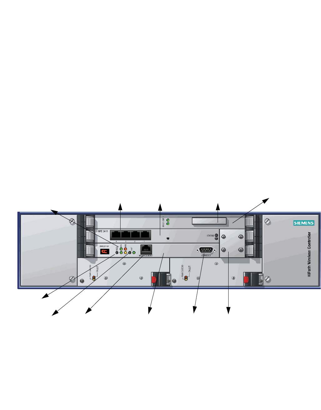
hwc_appendixa.fm
A31003-W1050-U100-2-7619, March 2008
HiPath Wireless Controller, Access Points and Convergence Software V5 R1 , C20/C2400 User Guide 371
HiPath Wireless Controller’s physical description
HiPath Wireless C2400 Controller front panel
A HiPath Wireless Controller’s physical description
This appendix describes the physical description and LEDs, SSD codes and their
description of the following models of the HiPath Wireless Controller:
•HiPath Wireless Controller C2400
•HiPath Wireless Controller C20
A.1 HiPath Wireless C2400 Controller front panel
The HiPath Wireless C2400 Controller is composed of the following three cards:
•Media/Persistent Storage Card
•Network Processor Card
•Host HiPath Wireless Controller Card
The following figure identifies the main components on the front panel of HiPath
Wireless C2400 Controller.
Figure 23 HiPath Wireless C2400 Controller front panel
The HiPath Wireless C2400 Controller has five LED lights and two switches on
its front panel.
Reset
switch
Console
port
RJ45
port
Media/Persistent
storage card
Network Processor
card
Host Controller
card Console
adapter
LED
lights
Data
ports
Diagnostic
switch
Compact
Flash slot
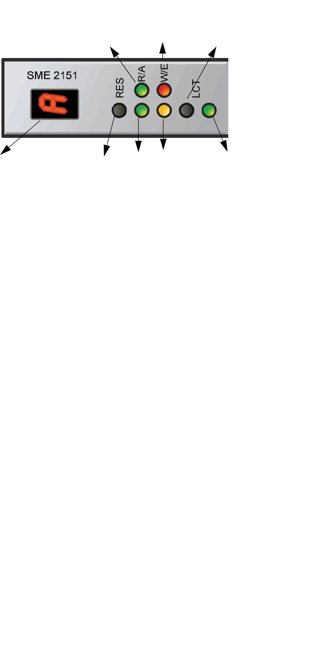
HiPath Wireless Controller’s physical description
hwc_appendixa.fm
HiPath Wireless C2400 Controller front panel
A31003-W1050-U100-2-7619,March 2008
372 HiPath Wireless Controller, Access Points and Convergence Software V5 R1 , C20/C2400 User Guide
Figure 24 HiPath Wireless C2400 Controller’s LED lights and switches
The description of the LED states and switches is provided below:
•Reset Switch – Reboots the system.
•RUN LED – Indicates the CPU’s initialization has completed and the system
is ready to provide application level services.
•ACT LED – Indicates the system’s software is in active running state.
•WARNING/ERROR LEDs – Indicate a problem in the running state of the
system.
•Whenever either of the alarm LEDs is lit, the seven-segment display
provides the corresponding code point for the error indication. When the
system is fully active and running, the console displays the letter Aas
seen in Figure 24.
•LCT Switch – The LCT button is used during the manufacturing process and
is inactive otherwise.
•INT LED – Not used in the current release.
Reset
switch
WARNING
LED
ERROR
LED
INT
LED
LCT switch
RUN
LED
ACT
LED
Seven-Segment display

hwc_appendixa.fm
HiPath Wireless Controller’s physical description
LED states and Seven Segment Display (SSD) codes
A31003-W1050-U100-2-7619, March 2008
HiPath Wireless Controller, Access Points and Convergence Software V5 R1 , C20/C2400 User Guide 373
A.2 LED states and Seven Segment Display (SSD) codes
Firmware initialization:
Note: Although the Active LED will be lit Green during the firmware initialization,
this LED state is irrelevant to the SSD display or the condition. You must ignore
the LED state during the firmware initialization.
Application initialization:
Active
LED
Warning
LED
Error
LED
SSD Codes Condition
Green 0 The processor has started; and the
firmware has taken control.
Green 3 The Host Controller Card has failed to
download Bootloader from Flash.
Green 4 The system is checking firmware
consistency.
Green 5 The system is formatting memory.
Green 6 The system is initializing load device.
Note: If the SSD code is stuck at 6 for
more than a minute, it implies that the
Network Processor Card is installed in
wrong slot.
Green 9 The system is loading subsystem.
Green b The system is starting the operation
system. The system is active.
Table 31 LED states and SSD codes during firmware initialization
Active
LED
Warning
LED
Error
LED
SSD Code Condition
Green 0 Application initialization started.
Green 1 Forwarding Engine initialization
complete. Application initialization.
Green A Application initialization complete.
System active.
Green H System halted. Administrator requested
halting of system.
Table 32 LED states and SSD codes during application initialization

HiPath Wireless Controller’s physical description
hwc_appendixa.fm
LED states and Seven Segment Display (SSD) codes
A31003-W1050-U100-2-7619,March 2008
374 HiPath Wireless Controller, Access Points and Convergence Software V5 R1 , C20/C2400 User Guide
Warning conditions:
Error conditions:
Active
LED
Warning
LED
Error
LED
SSD Code Condition
Green Yellow 1 High temperature reached.
Green Yellow 2 Fan unit failure. Rotation counter
indicates zero speed for one of the
lateral trays. May be the result of fan
tray removal.
Green Yellow 3 Power supply failure. Failed to detect
one of the power supplies. May be the
result of the fan tray removal of one of
the power supplies.
Green Yellow 4 FDD low sector count (40 backup
sectors remaining).
Green Yellow 5 FDD extremely low sector count (20
backup sectors remaining)
Table 33 LED states and SSD codes during warning conditions
Active
LED
Warning
LED
Error
LED
SSD Code Condition
Green Red 1 Failed to identify FDD. Possibly due to
removal of FDD card.
Green Red 2 Failed to initialize NPE card.
Green Red 3 Critical threshold reached (95C for
NPE).
The system will reboot.
Green Red 4 Full fan assembly failure (both trays).
The system will reboot.
Green Red 5 Application initialization failure. Startup
manager failed to initialize all the
components of the system.
The system will reboot.
Green Red 6 Lost connectivity with ethernet interface.
Possible failure of NPE card.
The system will reboot.
Green Red 7 MF 1000 card failure. Backup sectors
exhausted.
Green Red 8 NP 4000 card initialization failure.
Firmware self test (BIST) has detected
failure in one or more components
(memory, bus, interconnects)
Table 34 LED states and SSD codes during error conditions
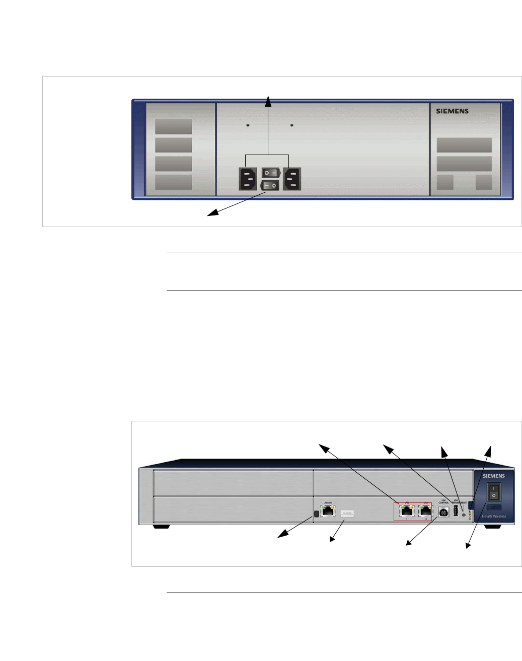
hwc_appendixa.fm
HiPath Wireless Controller’s physical description
HiPath Wireless C2400 Controller back panel
A31003-W1050-U100-2-7619, March 2008
HiPath Wireless Controller, Access Points and Convergence Software V5 R1 , C20/C2400 User Guide 375
A.3 HiPath Wireless C2400 Controller back panel
The following figure identifies the main components on the back panel of HiPath
Wireless C2400 Controller.
Figure 25 HiPath Wireless C2400 Controller back panel
Note: The hardware for the HiPath Wireless C2400 Controller Campus and the
HiPath Wireless C2400 Controller Enterprise are identical.
A.4 HiPath Wireless C20 Controller
A.4.1 HiPath Wireless C20 Controller front panel
Figure 26 HiPath Wireless C20 Controller front panel
Note: The hot swap lever is not enabled in the current release. Pulling the hot
swap lever will not affect the normal operation if the HiPath Wireless C20
Controller is already running. However, if you attempt to reboot the HiPath
Redundant
power supplies
Power switches
LAN ports
Admin
LEDs
USB server
USB control Power switch
Reset button
Hot Swap lever
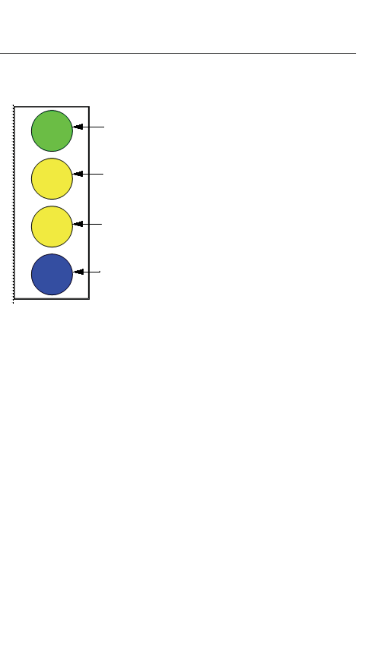
HiPath Wireless Controller’s physical description
hwc_appendixa.fm
HiPath Wireless C20 Controller
A31003-W1050-U100-2-7619,March 2008
376 HiPath Wireless Controller, Access Points and Convergence Software V5 R1 , C20/C2400 User Guide
Wireless C20 Controller with the hot swap lever pulled out, the controller will fail
to reboot. If you pull the hot swap lever while the HiPath Wireless C20 Controller
is in operation, the Hot Swap LED will light up.
The HiPath Wireless C20 Controller has four lights on its front panel.
Figure 27 HiPath Wireless C20 Controller LED lights
The functional definitions of the HiPath Wireless C20 Controller’s LEDs are
provided below:
•ACTIVITY LED – Indicates the CPU activity, including the amount of traffic
carried to and from the Wireless APs.
•STATUS LED – Indicates the normal state of the HiPath Wireless Controller
as seen by the system’s software. This LED covers all stages of the HiPath
Wireless Controller, ranging from restarting, to shutting-down. As long as the
HiPath Wireless Controller is running normally, this LED will remain lit.
•HDD Activity LED – Is hardware controlled to report Hard Drive Device (HDD)
activity.
•Hot Swap LED – Indicates that the hot swap lever on the HiPath Wireless
Controller is pulled out.
Activity
LED
Status
LED
HDD Activity
LED
Hot Swap
LED
hwc_appendixa.fm
HiPath Wireless Controller’s physical description
HiPath Wireless C20 Controller
A31003-W1050-U100-2-7619, March 2008
HiPath Wireless Controller, Access Points and Convergence Software V5 R1 , C20/C2400 User Guide 377
A.4.2 HiPath Wireless C20 Controller back panel
Figure 28 HiPath Wireless C20 Controller back panel
Power Supply

HiPath Wireless Controller’s physical description
hwc_appendixa.fm
HiPath Wireless C20 Controller
A31003-W1050-U100-2-7619,March 2008
378 HiPath Wireless Controller, Access Points and Convergence Software V5 R1 , C20/C2400 User Guide

hwc_appendixb.fm
A31003-W1050-U100-2-7619, March 2008
HiPath Wireless Controller, Access Points and Convergence Software V5 R1 , C20/C2400 User Guide 379
Regulatory information
B Regulatory information
Warning: Warnings identify essential information. Ignoring a warning can lead to
problems with the application.
This chapter provides the regulatory information for the HiPath Wireless
Controller C20/C2400 and the HiPath Wireless AP models:
•AP 2610/2620 (AP26XX series)
•AP 3610/3620 (AP36XX series)
Note: Throughout this appendix, the term ‘Wireless AP’ refers to both AP models
(AP26XX series and AP36XX series). Specific AP models are only identified in
this appendix where it is necessary to do so.
Note: For technical specifications and certification information for the HiPath
Wireless Outdoor AP, models AP 2650/2660, see the HiPath Wireless Outdoor
AP Installation Guide.
Configuration of the Wireless AP frequencies and power output are controlled by
the regional software license and proper selection of the country during initial
installation and set-up. Customers are only allowed to select the proper country
from their licensed regulatory domain related to that customer’s geographic
location, thus allowing the proper set-up of access points in accordance with local
laws and regulations. The Wireless AP must not be operated until properly
configured with the correct country setting or it may be in violation of the local laws
and regulations.
Warning: Changes or modifications made to the HiPath Wireless Controller or
the Wireless APs which are not expressly approved by Siemens could void the
user's authority to operate the equipment.
Only authorized Siemens service personnel are permitted to service the system.
Procedures that should be performed only by Siemens personnel are clearly
identified in this guide.
Note: The HiPath Wireless Controllers and the Wireless APs are in compliance
with the European Directive 2002/95/EC on the restriction of the use of certain
hazardous substances (RoHS) in electrical and electronic equipment.

Regulatory information
hwc_appendixb.fm
HiPath Wireless Controller C20/C2400
A31003-W1050-U100-2-7619,March 2008
380 HiPath Wireless Controller, Access Points and Convergence Software V5 R1 , C20/C2400 User Guide
B.1 HiPath Wireless Controller C20/C2400
Conformance standards and directives
Safety
•UL 60950-1 (U.S)
•CSA C22.2 No.60950-01-03 (Canada)
•2006/95/EC Low Voltage Directive (LVD)
•EN 60950-1 (Europe)
•IEC 60950-1 with applicable National Differences
•AS/NZS 60950.1 (Australia/New Zealand)
EMC (Emissions / Immunity)
•FCC Part 15, Subpart B, Class A (North America)
•ICES-003, Class A (Canadian Emissions)
•89/336/EEC EMC Directive
•EN 55022: Class A (European Emissions)
•EN 55024: includes EN 61000-2,3,4,5,6,11 (European Immunity)
•EN 61000-3-2: (Harmonics)
•EN 61000-3-3: (Flicker)
•IEC/CISPR 22: Class A (International Emissions)
•IEC/CISPR 24: includes IEC/EN 61000-4-2,3,4,5,6,11 (International
Immunity)
•Australia/New Zealand AS/NZS 3548 via EU standards (ACMA)
RoHS
•European Directive 2002/95/EC

hwc_appendixb.fm
Regulatory information
Wireless APs 26XX and 36XX
A31003-W1050-U100-2-7619, March 2008
HiPath Wireless Controller, Access Points and Convergence Software V5 R1 , C20/C2400 User Guide 381
B.2 Wireless APs 26XX and 36XX
B.2.1 Wi-Fi certification
The AP26XX is Wi-Fi certified under Certification ID # WFA4279 for operation in
accordance with IEEE 802.11a/b/g. The AP26XX Wireless APs with internal and
external antennas are designed and intended to be used indoors.
The AP36XX is Wi-Fi certified under Certification ID # WFA5917 for operation in
accordance with IEEE 802.11a/b/g/n. The AP36XX Wireless APs with internal
and external antennas are designed and intended to be used indoors.
Note: Operation in the European Community and rest of the world may be
dependant on securing local licenses, certifications, and regulatory approvals.
B.2.2 AP2620 external antenna AP
Optional approved 3rd party external antennas
The AP2620 external antenna APs can also be used with optional certified
external antennas.
Antenna diversity
There are some limitations for using different antennas and Tx/Rx diversity:
•If Alternate antenna diversity is used for Tx or Rx, then the same antenna
model must be used as left and right antennas. In addition, if cables are used
to connect external antennas, the cables must be of the same length and
similar attenuation. If these rules are not respected, antenna diversity will not
function properly and there will be degradation in the link budget in both
directions.
•You can choose to install only one antenna provided that both Tx and Rx
diversity are configured to use that antenna and only that antenna. You can
choose to install one antenna for 11b/g band and one antenna for 11a band,
provided that the antenna diversity is configured appropriately on both radios.
Sensor support
Changing the antenna on sensors is not supported (at this stage) for the following
reasons:
•The sensor factors the antenna gain and pattern in its calculations and
therefore it needs to know the antenna type and gain.

Regulatory information
hwc_appendixb.fm
Wireless APs 26XX and 36XX
A31003-W1050-U100-2-7619,March 2008
382 HiPath Wireless Controller, Access Points and Convergence Software V5 R1 , C20/C2400 User Guide
•The sensor operating in mitigation mode becomes a transmitter and must
obey the same CTLs as the normal AP software.
•Neither the sensor nor the HiPath Wireless Manager HiGuard support
configuring the antenna.

hwc_appendixb.fm
Regulatory information
Wireless APs 26XX and 36XX
A31003-W1050-U100-2-7619, March 2008
HiPath Wireless Controller, Access Points and Convergence Software V5 R1 , C20/C2400 User Guide 383
B.2.3 United States
B.2.3.1 FCC Declaration of Conformity Statement
This device complies with Part 15 of the FCC Rules. Operation is subject to the
following two conditions:
•This device may not cause harmful interference.
•This device must accept any interference received, including interference that
may cause undesired operation.
This equipment has been tested and found to comply with the limits for a Class B
digital device, pursuant to Part 15 of the FCC Rules. These limits are designed to
provide reasonable protection against harmful interference when the equipment
is operated in a residential and business environment. This equipment generates,
uses, and radiates radio frequency energy, and if not installed and used in
accordance with instructions, may cause harmful interference. However, there is
no guarantee that interference will not occur. If this equipment does cause
harmful interference, which can be determined by turning the equipment off and
on, the user is encouraged to try to correct the interference by one or more of the
following measures:
•Reorient or relocate the receiving antenna.
•Increase the separation between the equipment or devices.
•Connect the equipment to an outlet other than the receiver's.
•Consult a dealer or an experienced radio/TV technician for suggestions.
B.2.3.2 USA conformance standards
This equipment meets the following conformance standards:
Safety
•UL 60950-1
•UL 2043 Plenum Rated as part of UL 60950-1. Suitable for use in
environmental air space in accordance with Section 300.22.C of the National
Electrical Code.
EMC
•FCC CFR 47 Part 15, Class B
Radio transceiver
•CFR 47 Part 15.247, Subpart C (2.4 GHz)

Regulatory information
hwc_appendixb.fm
Wireless APs 26XX and 36XX
A31003-W1050-U100-2-7619,March 2008
384 HiPath Wireless Controller, Access Points and Convergence Software V5 R1 , C20/C2400 User Guide
•CFR 47 Part 15.407, Subpart E (5 GHz)
Other
•IEEE 802.11a (5 GHz)
•IEEE 802.11b/g (2.4 GHz)
•IEEE 802.11n (AP36XX)
•IEEE 802.3af (PoE)
Warning: The Wireless APs must be installed and used in strict accordance with
the manufacturer's instructions as described in this guide and related
documentation for the device to which the Wireless AP is connected. Any other
installation or use of the product violates FCC Part 15 regulations.
Operation of the Wireless AP is restricted for indoor use only, specifically in the
UNII 5.15 - 5.25 GHz band in accordance with 47 CFR 15.407(e).
This Part 15 radio device operates on a non-interference basis with other devices
operating at the same frequency when using antennas provided or other Siemens
certified antennas. Any changes or modification to the product not expressly
approved by Siemens could void the user's authority to operate this device.
For the product available in the USA market, only channels 1 to 11 can be
operated. Selection of other channels in the 2.4 GHz band is not possible.
B.2.3.3 FCC RF Radiation Exposure Statement
The Wireless AP complies with FCC RF radiated exposure limits set forth for an
uncontrolled environment. End users must follow the specific operating
instructions for satisfying RF exposure compliance. This device has been tested
and has demonstrated compliance when simultaneously operated in the 2.4 GHz
and 5 GHz frequency ranges. This device must not be co-located or operated in
conjunction with any other antenna or transmitter.
Caution: The radiated output power of the Wireless AP is below the FCC radio
frequency exposure limits as specified in "Guidelines for Human Exposure to
Radio Frequency Electromagnetic Fields" (OET Bullet 65, Supplement C). This
equipment should be installed and operated with a minimum distance of 25 cm
between the radiator and your body or other co-located operating antennas.

hwc_appendixb.fm
Regulatory information
Wireless APs 26XX and 36XX
A31003-W1050-U100-2-7619, March 2008
HiPath Wireless Controller, Access Points and Convergence Software V5 R1 , C20/C2400 User Guide 385
B.2.3.4 AP2620 optional 3rd party external antennas
The AP2620 external antenna APs can also be used with optional certified 3rd
party antennas. However, in order to comply with the local laws and regulations,
an approval may be required by the local regulatory authorities. The following
optional antennas have been tested and approved for use with the external
antenna model.
Caution: When using an approved 3rd party external antenna (other than the
default), the power must be adjusted according to these tables.
Professional installation
To comply with FCC part 15 rules in the United States, the system must be
professionally installed to ensure compliance with the Part 15 certification. It is the
responsibility of the operator and professional installer to ensure that only
certified systems are deployed in the United States. The use of the system in any
other combination (such as co-located antennas transmitting the same
information) is expressly forbidden. The following are the requirements of
professional installation:
•The device cannot be sold retail to the general public or by mail order. It must
be sold to dealers.
•Installation must be controlled.
•Installation must be carried out by licensed professionals (equipment sold to
dealers who hire installers)
•Installation requires special training (special programming and antenna and
cable installations)
•The intended use is generally not for the general public. Instead, it is
generally for industry/commercial use.

Regulatory information
hwc_appendixb.fm
Wireless APs 26XX and 36XX
A31003-W1050-U100-2-7619,March 2008
386 HiPath Wireless Controller, Access Points and Convergence Software V5 R1 , C20/C2400 User Guide
Note: The qualification testing and results are based on above described
antennas, cable types, lengths, and connector types. Other cable lengths and
connector types are also available which are specified by the suffix part of the part
numbers (for example, SR2405135Dxxxxxx, where the xxxxxx suffix represents
cable length and/or connector type). The antenna feedline used in testing are the
minimum cable length. Longer cable may be used with losses greater than or
equal to the cables used for testing. The maximum power settings must be
adjusted according to these tables.
Note: If one of the following antenna is used, you must select an operating
channel (on the Wireless APs configuration pages) and the corresponding
allowed max power from the values listed in Table 36. DO NOT select a higher
power than the value listed in Table 36.
#Model Application Shape Gain (dBi) Frequency
(MHz)
Coax Cable
Length/Type
Connector Type
Cushcraft
#1 SR2405135D
xxxxxx
indoor Directional 5 2400-2500 3 feet / 19AWG
CMP(ETL)
C(ETL) 9700851
RPSMA
#2 S24493DSxxx
xxx
indoor Omni, 2
inputs
3 2400-2500
4900-5990
3 feet / 19AWG
CMP(ETL)
C(ETL) 9700851
RPSMA, 2ea.
#3 SL24513Pxxx
xxx
indoor Omni 3 2400-2500
5150-5350
3 feet / 19AWG
CMP(ETL)
C(ETL) 9700851
RPSMA
#4 S24497Pxxxx
xx
indoor Directional 7 2400-2500
4900-5990
3 feet / 19AWG
CMP(ETL)
C(ETL) 9700851
RPSMA
Hyperlink Tech
#5 HG2458CUxx
x
indoor Omni 3 2300-2600
4900-6000
1 foot / 20AWG
Coleman Cable
921021
N-female
Maxrad
#6 MDO24005PT
xxxxxx
indoor Omni, 2
inputs
5.2 2400-2485 3 feet / 19AWG
CMP(ETL)
C(ETL) 9700851
RPSMA, 2ea.
Table 35 List of FCC approved antennas

hwc_appendixb.fm
Regulatory information
Wireless APs 26XX and 36XX
A31003-W1050-U100-2-7619, March 2008
HiPath Wireless Controller, Access Points and Convergence Software V5 R1 , C20/C2400 User Guide 387
Antenna
Antenna
#1
Cushcraft
SR2405135
Dxxxxxx
Antenna
#2
Cushcraft
S24493DSx
xxxxx
Antenna
#3
Cushcraft
SL24513Px
xxxxx
Antenna
#4
Cushcraft
S24497Pxx
xxxx
Antenna
#5 Hyperlink
Tech
HG2458CUxx
x
Antenna
#6
Maxrad
MDO24005PT
xxxxxx
Frequency
(MHz)
Ch. No. Power limit
(dBm)
Power limit
(dBm)
Power limit
(dBm)
Power limit
(dBm)
Power limit
(dBm)
Power limit
(dBm)
11b
241211618 171617 17
241721717 171617 17
242231818 181818 18
242741818 181818 18
243251818 181818 18
243761818 181818 18
244271818 181818 18
244781818 181818 18
245291818 181818 18
2457 10 18 18 18 18 18 18
2462 11 18 18 18 18 18 18
11g
241211013 131012 13
241721415 151415 14
242231516 161516 16
242741618 181617 17
243251618 181718 18
243761618 181718 18
244271818 181818 18
244781818 181818 18
245291818 181818 18
2457 10 17 17 17 17 17 18
2462 11 14 14 14 14 14 14
Table 36 FCC Antenna channel-power information

Regulatory information
hwc_appendixb.fm
Wireless APs 26XX and 36XX
A31003-W1050-U100-2-7619,March 2008
388 HiPath Wireless Controller, Access Points and Convergence Software V5 R1 , C20/C2400 User Guide
Caution: Channels designated as N/S are not supported by the antenna and
must not be selected from the Wireless APs configuration pages.
Caution: For antenna #3 (Cushcraft SL24513Pxxxxxx), do not select the Auto
channel selection (on the Wireless APs configuration pages) for the 11a radio.
Instead, only select a channel from the listed supported channels in Table 36.
Operating on a channel that is NOT supported (N/S) is in violation of the law.
Caution: If you select the Auto channel selection (on the Wireless APs
configuration pages), you must also select the power values listed in Table 37.
DO NOT select a higher power than the value listed in Table 37.
11a
5180 36 N/S 17 17 17 17 N/S
5200 40 N/S 17 17 17 17 N/S
5220 44 N/S 17 17 17 17 N/S
5240 48 N/S 17 17 17 17 N/S
5260 52 N/S 18 18 18 18 N/S
5280 56 N/S 18 18 18 18 N/S
5300 60 N/S 18 18 18 18 N/S
5320 64 N/S 18 18 18 18 N/S
5745 149 N/S 15 N/S 15 15 N/S
5765 153 N/S 15 N/S 15 15 N/S
5785 157 N/S 14 N/S 14 14 N/S
5805 161 N/S 14 N/S 14 14 N/S
5825 165 N/S 14 N/S 14 14 N/S
Antenna
Antenna
#1
Cushcraft
SR2405135
Dxxxxxx
Antenna
#2
Cushcraft
S24493DSx
xxxxx
Antenna
#3
Cushcraft
SL24513Px
xxxxx
Antenna
#4
Cushcraft
S24497Pxx
xxxx
Antenna
#5 Hyperlink
Tech
HG2458CUxx
x
Antenna
#6
Maxrad
MDO24005PT
xxxxxx
Frequency
(MHz)
Ch. No. Power limit
(dBm)
Power limit
(dBm)
Power limit
(dBm)
Power limit
(dBm)
Power limit
(dBm)
Power limit
(dBm)
Table 36 FCC Antenna channel-power information

hwc_appendixb.fm
Regulatory information
Wireless APs 26XX and 36XX
A31003-W1050-U100-2-7619, March 2008
HiPath Wireless Controller, Access Points and Convergence Software V5 R1 , C20/C2400 User Guide 389
RF safety distance
The antennas used for this transmitter must be installed to provide a separation
distance of at least 25 cm from all persons and must not be co-located or
operating in conjunction with another antenna or transmitter.
Antenna 11a (dBm) 11b/g (dBm)
#1 N/S 10
#2 14 13
#3 17 13
#4 14 10
#5 14 12
#6 N/S 13
Table 37 Auto channel selection

Regulatory information
hwc_appendixb.fm
Wireless APs 26XX and 36XX
A31003-W1050-U100-2-7619,March 2008
390 HiPath Wireless Controller, Access Points and Convergence Software V5 R1 , C20/C2400 User Guide
B.2.4 Canada
B.2.4.1 Department of Communications Compliance
Statement
This digital apparatus does not exceed the Class B limits for radio noise
emissions from digital apparatus as set out in the interference-causing equipment
standard entitled "Digital Apparatus," ICES-003 of the Department of
Communications.
Cet appareil numerique respecte les limites de bruits radioelectriques applicables
aux appareils numeriques de Classe B prescrites dans la norme sur le materiel
brouilleur: "Appareils Numeriques," NMB-003 edictee par le ministere des
Communications.
This device complies with Part 15 of the FCC Rules and Canadian Standard RSS-
210. Operation is subject to the following conditions:
•This device may not cause harmful interference.
•This device must accept any interference received, including interference that
may cause undesired operation.
•This Class B digital apparatus complies with Canadian ICES-003.
•Operation in the 5150-5250 MHz band is only for indoor usage to reduce
potential for harmful interference to co-channel mobile satellite systems.
•Please note that high power radars are allocated as primary users (meaning
they have priority) and can cause interference in the 5250-5350 MHz and
5470-5725 MHz bands of LE-LAN devices.
•For the product available in the Canadian market, only channels 1 to 11 can
be operated. Selection of other channels in the 2.4 GHz band is not possible.
•The maximum antenna gain permitted for the AP26XX operating in the
5250-5350 MHz band to comply with the e.i.r.p. limit is 4.3 dBi for the internal
antenna and 5 dBi for the default external antenna that is shipped with the
unit. To comply with the e.i.r.p. limit with the optional external antennas, refer
to Table 39.
•The maximum antenna gain permitted for the AP26XX operating in the
5725-5825 MHz band to comply with the e.i.r.p. limit is 4.3 dBi for the internal
antenna and 5 dBi for the default external antenna that is shipped with the
unit. To comply with the e.i.r.p. limit with the optional external antennas, refer
to Table 39.
•The maximum antenna gain permitted for the AP36XX operating in the bands
5250-5350 MHz and 5470-5725 MHz to comply with the e.i.r.p. limit is 6 dBi
for the internal antenna and 5 dBi for the external antenna.

hwc_appendixb.fm
Regulatory information
Wireless APs 26XX and 36XX
A31003-W1050-U100-2-7619, March 2008
HiPath Wireless Controller, Access Points and Convergence Software V5 R1 , C20/C2400 User Guide 391
•The maximum antenna gain permitted for the AP36XX operating in the
5725-5825 MHz band to comply with the e.i.r.p. limits specified for
point-to-point and non point-to-point operation as appropriate is 6 dBi for the
internal antenna and 5 dBi for the external antenna.
B.2.4.2 Canada conformance standards
This equipment meets the following conformance standards:
Safety
•C22.2 No.60950-1-03
•UL 2043 Plenum Rated as part of UL 60950-1. Suitable for use in
environmental air space in accordance with Sections 2-128, 12-010(3) and
12-100 of the Canadian Electrical Code, Part 1, C22.1
EMC
•ICES-003, Class B
Radio transceiver
•RSS-210 (2.4 GHz and 5GHz)
Other
•IEEE 802.11a (5 GHz)
•IEEE 802.11b/g (2.4 GHz)
•IEEE 802.11n (AP36XX)
•IEEE 802.3af (PoE)
B.2.4.3 AP2620 optional 3rd party external antennas
The AP2620 external antenna APs can also be used with optional certified 3rd
party antennas. However, in order to comply with the local laws and regulations,
an approval may be required by the local regulatory authorities. The following
optional antennas have been tested with and approved for use with the external
antenna model.
Caution: When using an approved 3rd party external antenna (other than the
default), the power must be adjusted according to these tables.
Professional installation
This device must be professionally installed. The following are the requirements
of professional installation:

Regulatory information
hwc_appendixb.fm
Wireless APs 26XX and 36XX
A31003-W1050-U100-2-7619,March 2008
392 HiPath Wireless Controller, Access Points and Convergence Software V5 R1 , C20/C2400 User Guide
•The device cannot be sold retail to the general public or by mail order. It must
be sold to dealers.
•Installation must be controlled.
•Installation must be carried out by licensed professionals (equipment sold to
dealers who hire installers)
•Installation requires special training (special programming and antenna and
cable installations)
The intended use is generally not for the general public. Instead, it is generally for
industry/commercial use.
#Model Application Shape Gain (dBi) Frequency
(MHz)
Coax Cable
Length/Type
Connector
Type
Cushcraft
#1 SR2405135Dx
xxxxx
indoor Directional 5 2400-2500 3 feet / 19AWG
CMP(ETL)
C(ETL)
9700851
RPSMA
#2 S24493DSxxx
xxx
indoor Omni, 2 inputs 3 2400-2500
4900-5990
3 feet / 19AWG
CMP(ETL)
C(ETL)
9700851
RPSMA, 2ea.
#3 SL24513Pxxx
xxx
indoor Omni 3 2400-2500
5150-5350
3 feet / 19AWG
CMP(ETL)
C(ETL)
9700851
RPSMA
#4 S24497Pxxxx
xx
indoor Directional 7 2400-2500
4900-5990
3 feet / 19AWG
CMP(ETL)
C(ETL)
9700851
RPSMA
Hyperlink Tech
#5 HG2458CUxx
x
indoor Omni 3 2300-2600
4900-6000
1 foot / 20AWG
Coleman
Cable 921021
N-female
Maxrad
#6 MDO24005PT
xxxxxx
indoor Omni, 2 inputs 5.2 2400-2485 3 feet / 19AWG
CMP(ETL)
C(ETL)
9700851
RPSMA, 2ea.
Table 38 List of IC (Industry Canada) approved antennas

hwc_appendixb.fm
Regulatory information
Wireless APs 26XX and 36XX
A31003-W1050-U100-2-7619, March 2008
HiPath Wireless Controller, Access Points and Convergence Software V5 R1 , C20/C2400 User Guide 393
Note: The qualification testing and results are based on above described
antennas, cable types, lengths, and connector types. Other cable lengths and
connector types are also available which are specified by the suffix part of the part
numbers (ex. SR2405135Dxxxxxx, where the xxxxxx suffix represents cable
length and/or connector type). The antenna feedline used in testing are the
minimum cable length. Longer cable may be used with losses greater than or
equal to the cables used for testing. The maximum power settings must be
adjusted according to these tables.
Note: If one of the following antenna is used, you must select an operating
channel (on the Wireless APs configuration pages) and the corresponding
allowed max power from the values listed in Table 39. DO NOT select a higher
power than the value listed in Table 39.
Antenna
Antenna
#1 Cushcraft
SR2405135D
xxxxxx
Antenna
#2 Cushcraft
S24493DSxx
xxxx
Antenna
#3 Cushcraft
SL24513Pxx
xxxx
Antenna
#4
Cushcraft
S24497Pxx
xxxx
Antenna
#5 Hyperlink
Tech
HG2458CUxxx
Antenna
#6
Maxrad
MDO24005P
Txxxxxx
Frequency
(MHz)
Ch. No. Power limit
(dBm)
Power limit
(dBm)
Power limit
(dBm)
Power limit
(dBm)
Power limit
(dBm)
Power limit
(dBm)
11b241211618171617 17
241721717171617 17
242231818181818 18
242741818181818 18
243251818181818 18
243761818181818 18
244271818181818 18
244781818181818 18
245291818181818 18
2457 10 18 18 18 18 18 18
2462 11 18 18 18 18 18 18
Table 39 IC Antenna channel-power information

Regulatory information
hwc_appendixb.fm
Wireless APs 26XX and 36XX
A31003-W1050-U100-2-7619,March 2008
394 HiPath Wireless Controller, Access Points and Convergence Software V5 R1 , C20/C2400 User Guide
11g
2412 1 10 13 13 10 12 13
2417 2 14 15 15 14 15 14
2422 3 15 16 16 15 16 16
2427 4 16 18 18 16 17 17
2432 5 16 18 18 17 18 18
2437 6 16 18 18 17 18 18
2442 7 18 18 18 18 18 18
2447 8 18 18 18 18 18 18
2452 9 18 18 18 18 18 18
2457101717171717 18
2462111414141414 14
11a
5180 36 N/S 17 17 17 17 N/S
5200 40 N/S 17 17 17 17 N/S
5220 44 N/S 17 17 17 17 N/S
5240 48 N/S 17 17 17 17 N/S
5260 52 N/S 18 18 18 18 N/S
5280 56 N/S 18 18 18 18 N/S
5300 60 N/S 18 18 18 18 N/S
5320 64 N/S 18 18 18 18 N/S
5745 149 N/S 15 N/S 15 15 N/S
5765 153 N/S 15 N/S 15 15 N/S
5785 157 N/S 14 N/S 14 14 N/S
5805 161 N/S 14 N/S 14 14 N/S
5825 165 N/S 14 N/S 14 14 N/S
Antenna
Antenna
#1 Cushcraft
SR2405135D
xxxxxx
Antenna
#2 Cushcraft
S24493DSxx
xxxx
Antenna
#3 Cushcraft
SL24513Pxx
xxxx
Antenna
#4
Cushcraft
S24497Pxx
xxxx
Antenna
#5 Hyperlink
Tech
HG2458CUxxx
Antenna
#6
Maxrad
MDO24005P
Txxxxxx
Frequency
(MHz)
Ch. No. Power limit
(dBm)
Power limit
(dBm)
Power limit
(dBm)
Power limit
(dBm)
Power limit
(dBm)
Power limit
(dBm)
Table 39 IC Antenna channel-power information
hwc_appendixb.fm
Regulatory information
Wireless APs 26XX and 36XX
A31003-W1050-U100-2-7619, March 2008
HiPath Wireless Controller, Access Points and Convergence Software V5 R1 , C20/C2400 User Guide 395
Caution: Channels designated as N/S are not supported by the antenna and
must not be selected from the Wireless APs configuration pages.
Caution: For antenna #3 (Cushcraft SL24513Pxxxxxx), do not select the Auto
channel selection (on the Wireless APs configuration pages) for the 11a radio.
Instead, only select a channel from the listed supported channels in Table 36.
Operating on a channel that is NOT supported (N/S) is in violation of the law.
Caution: If you select the Auto channel selection (on the Wireless APs
configuration pages), you must also select the power values listed in Table 40.
DO NOT select a higher power than the value listed in Table 40.
RF safety distance
The antennas used for this transmitter must be installed to provide a separation
distance of at least 25 cm from all persons and must not be co-located or
operating in conjunction with another antenna or transmitter.
Antenna 11a (dBm) 11b/g (dBm)
#1 N/S 10
#2 14 13
#3 17 13
#4 14 10
#5 14 12
#6 N/S 13
Table 40 Auto channel selection

Regulatory information
hwc_appendixb.fm
Wireless APs 26XX and 36XX
A31003-W1050-U100-2-7619,March 2008
396 HiPath Wireless Controller, Access Points and Convergence Software V5 R1 , C20/C2400 User Guide
B.2.5 European community
The Wireless APs are designed for use in the European Union and other
countries with similar regulatory restrictions where the end user or installer is
allowed to configure the Wireless AP for operation by entry of a country code
relative to a specific country. Upon connection to the controller, the software will
prompt the user to select a country code. After the country code is selected, the
controller will set up the Wireless AP with the proper frequencies and power
outputs for that country code.
Although outdoor use may be allowed and may be restricted to certain
frequencies and/or may require a license for operation, the Wireless AP is
intended for indoor use and must be installed in a proper indoor location. Use the
installation utility provided with the controller software to ensure proper set-up in
accordance with all European spectrum usage rules. Contact local Authority for
procedure to follow and regulatory information. For more details on legal
combinations of frequencies, power levels and antennas, contact Siemens.
Declaration of Conformity with R&TTE Directive of the European Union 1999/5/
EC
The following symbol indicates compliance with the Essential Requirements of
the R&TTE Directive of the European Union (1999/5/EC).

hwc_appendixb.fm
Regulatory information
Wireless APs 26XX and 36XX
A31003-W1050-U100-2-7619, March 2008
HiPath Wireless Controller, Access Points and Convergence Software V5 R1 , C20/C2400 User Guide 397
B.2.5.1 Declaration of Conformity in Languages of the
European Community
English Hereby, Siemens, declares that this Radio LAN device is in compliance
with the essential requirements and other relevant provisions of Directive
1999/5/EC.
Finnish Valmistaja Siemens vakuuttaa täten että Radio LAN device tyyppinen laite
on direktiivin 1999/5/EY oleellisten vaatimusten ja sitä koskevien
direktiivin muiden ehtojen mukainen.
Dutch Hierbij verklaart Siemens dat het toestel Radio LAN device in
overeenstemming is met de essentiële eisen en de andere relevante
bepalingen van richtlijn 1999/5/EG.
Bij deze verklaart Siemens dat deze Radio LAN device voldoet aan de
essentiële eisen en aan de overige relevante bepalingen van Richtlijn
1999/5/EC.
French Par la présente Siemens déclare que l'appareil Radio LAN device est
conforme aux exigences essentielles et aux autres dispositions
pertinentes de la directive 1999/5/CE.
Par la présente, Siemens déclare que ce Radio LAN device est conforme
aux exigences essentielles et aux autres dispositions de la directive 1999/
5/CE qui lui sont applicables.
Swedish Härmed intygar Siemens att denna Radio LAN device står I
överensstämmelse med de väsentliga egenskapskrav och övriga
relevanta bestämmelser som framgår av direktiv 1999/5/EG.
Danish Undertegnede Siemens erklærer herved, at følgende udstyr Radio LAN
device overholder de væsentlige krav og øvrige relevante krav i direktiv
1999/5/EF.
German Hiermit erklärt Siemens die Übereinstimmung des "WLAN Wireless
Controller bzw. Access Points" mit den grundlegenden Anforderungen
und den anderen relevanten Festlegungen der Richtlinie 1999/5/EG.
Greek ȂǼ ȉǾȃ ȆǹȇȅȊȈǹ Siemens ǻǾȁȍȃǼǿ ȅȉǿ Radio LAN device
ȈȊȂȂȅȇĭȍȃǼȉǹǿ ȆȇȅȈ ȉǿȈ ȅȊȈǿȍǻǼǿȈ ǹȆǹǿȉǾȈǼǿȈ Ȁǹǿ ȉǿȈ
ȁȅǿȆǼȈ ȈȋǼȉǿȀǼȈ ǻǿǹȉǹȄǼǿȈ ȉǾȈ ȅǻǾīǿǹȈ 1999/5/ǼȀ.
Icelandic Siemens lysir her med yfir að thessi bunadur, Radio LAN device, uppfyllir
allar grunnkrofur, sem gerdar eru i R&TTE tilskipun ESB nr 1999/5/EC.
Italian Con la presente Siemens dichiara che questo Radio LAN device è
conforme ai requisiti essenziali ed alle altre disposizioni pertinenti stabilite
dalla direttiva 1999/5/CE.
Spanish Por medio de la presente Siemens declara que el Radio LAN device
cumple con los requisitos esenciales y cualesquiera otras disposiciones
aplicables o exigibles de la Directiva 1999/5/CE.
Portuguese Siemens declara que este Radio LAN device está conforme com os
requisitos essenciais e outras disposições da Directiva 1999/5/CE.
Malti Hawnhekk, Siemens, jiddikjara li dan Radio LAN device jikkonforma mal-
htigijiet essenzjali u ma provvedimenti ohrajn relevanti li hemm fid-
Dirrettiva 1999/5/EC.

Regulatory information
hwc_appendixb.fm
Wireless APs 26XX and 36XX
A31003-W1050-U100-2-7619,March 2008
398 HiPath Wireless Controller, Access Points and Convergence Software V5 R1 , C20/C2400 User Guide
New Member States requirements of Declaration of Conformity
Estonian Käesolevaga kinnitab Siemens seadme Radio LAN device vastavust
direktiivi 1999/5/EÜ põhinõuetele ja nimetatud direktiivist tulenevatele
teistele asjakohastele sätetele.
Hungary Alulírott, Siemens nyilatkozom, hogy a Radio LAN device megfelel a
vonatkozó alapvetõ követelményeknek és az 1999/5/EC irányelv egyéb
elõírásainak.
Slovak Siemens týmto vyhlasuje, že Radio LAN device spĎĖa základné
požiadavky a všetky príslušné ustanovenia Smernice 1999/5/ES.
Czech Siemens tímto prohlašuje, že tento Radio LAN device je ve shodČ se
základními požadavky a dalšími pĜíslušnými ustanoveními smČrnice
1999/5/ES."
Slovenian Šiuo Siemens deklaruoja, kad šis Radio LAN device atitinka esminius
reikalavimus ir kitas 1999/5/EB Direktyvos nuostatas.
Latvian Ar šo Siemens deklarƝ, ka Radio LAN device atbilst DirektƯvas 1999/5/EK
bnjtiskajƗm prasƯbƗm un citiem ar to saistƯtajiem noteikumiem
Lithuanian Siemens deklaruoja, kad Radio LAN device atitinka 1999/5/EC
Direktyvos esminius reikalavimus ir kitas nuostatas".
Polish Niniejszym, Siemens, deklarujĊ,Īe Radio LAN device speánia
wymagania zasadnicze oraz stosowne postanowienia zawarte
Dyrektywie 1999/5/EC.

hwc_appendixb.fm
Regulatory information
Wireless APs 26XX and 36XX
A31003-W1050-U100-2-7619, March 2008
HiPath Wireless Controller, Access Points and Convergence Software V5 R1 , C20/C2400 User Guide 399
B.2.5.2 European conformance standards
This equipment meets the following conformance standards:
Safety
•2006/95/EC Low Voltage Directive (LVD)
•IEC/EN 60950-1 + National Deviations
EMC (Emissions / Immunity)
•89/336/EEC EMC Directive
•EN 55011/CISPR 11, Class B, Group 1 ISM
•EN 55022/CISPR 22, Class B
•EN 55024/CISPR 24, includes IEC/EN 61000-4-2,3,4,5,6,11
•EN 61000-3-2 and -3-3 (Harmonics and Flicker)
•EN 60601-1-2 (EMC immunity for medical equipment)
•EN 50385 (EMF)
•ETSI/EN 301 489-1 & -17
Radio transceiver
•R&TTE Directive 1999/5/EC
•ETSI/EN 300 328 (2.4 GHz)
•ETSI/EN 301 893 (5 GHz)
Other
•IEEE 802.11a (5 GHz)
•IEEE 802.11b/g (2.4 GHz)
•IEEE 802.11n (AP36XX)
•IEEE 802.3af (PoE)
RoHS
•European Directive 2002/95/EC

Regulatory information
hwc_appendixb.fm
Wireless APs 26XX and 36XX
A31003-W1050-U100-2-7619,March 2008
400 HiPath Wireless Controller, Access Points and Convergence Software V5 R1 , C20/C2400 User Guide
B.2.5.3 AP2620 optional 3rd party external antennas
The AP2620 external antenna APs can also be used with optional certified 3rd
party antennas. However, in order to comply with the local laws and regulations,
an approval may be required by the local regulatory authorities. The following
optional antennas have been tested with and approved for use with the external
antenna model.
Caution: When using an approved 3rd party external antenna (other than the
default), the power must be adjusted according to these tables.
Professional installation
This device must be professionally installed. The following are the requirements
of professional installation:
•The device cannot be sold retail to the general public or by mail order. It must
be sold to dealers.
•Installation must be controlled.
•Installation must be carried out by licensed professionals (equipment sold to
dealers who hire installers)
•Installation requires special training (special programming and antenna and
cable installations)
The intended use is generally not for the general public. Instead, it is generally for
industry/commercial use.

hwc_appendixb.fm
Regulatory information
Wireless APs 26XX and 36XX
A31003-W1050-U100-2-7619, March 2008
HiPath Wireless Controller, Access Points and Convergence Software V5 R1 , C20/C2400 User Guide 401
Note: If one of the following antenna is used, you must select an operating
channel (on the Wireless APs configuration pages) and the corresponding
allowed max power from the values listed in Table 42. DO NOT select a higher
power than the value listed in Table 42.
#Model Location Type Gain (dBi) Frequency (MHz)
Huber+Suhner
#1 SOA
2454/360/7/20/DF
outdoor-capable Omni 6
8
2400-2500
4900-5875
#2 SPA
2456/75/9/0/DF
outdoor-capable Planar
2 or 1 inputs
9 2400-2500
5150-5875
#3 SPA
2400/80/9/0/DS
outdoor-capable Planar
2 inputs
8.5 2300-2500
#4 SWA
0859/360/4/10/V
outdoor-capable Omni 7 2400-5875
#5 SOA
2400/360/4/0/DS
outdoor-capable Omni 3.5 2400-2500
#6 SPA
2400/40/14/0/DS
outdoor-capable Planar
2 inputs
13.5 2400-2500
#7 SWA
2459/360/4/45/V
outdoor-capable Omni >4 2400-5875
Table 41 Approved antenna list for Europe

Regulatory information
hwc_appendixb.fm
Wireless APs 26XX and 36XX
A31003-W1050-U100-2-7619,March 2008
402 HiPath Wireless Controller, Access Points and Convergence Software V5 R1 , C20/C2400 User Guide
Antenna
Antenna
#1
Huber
+Suhner
SOA 2454/
360/7/20/
DF
Antenna
#2
Huber
+Suhner
SPA 2456/
75/9/0/DF
Antenna
#3
Huber
+Suhner
SPA 2400/
80/9/0/DS
Antenna
#4
Huber
+Suhner
SWA 0859/
360/4/10/V
Antenna
#5
Huber
+Suhner
SOA 2400/
360/4/0/DS
Antenna
#6
Huber
+Suhner
SPA 2400/
40/14/0/DS
Antenna
#7
Huber
+Suhner
SWA 2459/
360/4/45/V
Frequency
(MHz)
Ch.
No.
Power limit
(dBm)
Power limit
(dBm)
Power
limit
(dBm)
Power limit
(dBm)
Power limit
(dBm)
Power
limit
(dBm)
Power
limit
(dBm)
11b
2412 1 15 14 14 15 15 9 15
2417 2 15 14 14 15 15 9 15
2422 3 15 14 14 15 15 9 15
2427 4 15 14 14 15 15 9 15
2432 5 15 14 14 15 15 9 15
2437 6 15 14 14 15 15 9 15
2442 7 15 14 14 15 15 9 15
2447 8 15 14 14 15 15 9 15
2452 9 15 14 14 15 15 9 15
2457101514 14 15159 15
2462111514 14 15159 15
2467121514 14 15159 15
2472131514 15 151510 15
11g
2412 1 15 13 14 15 15 9 15
2417 2 15 13 14 15 15 9 15
2422 3 15 13 14 15 15 9 15
2427 4 15 13 14 15 15 9 15
2432 5 15 13 14 15 15 9 15
2437 6 15 13 14 15 15 9 15
2442 7 15 14 14 15 15 10 15
2447 8 15 14 14 15 15 10 15
2452 9 15 14 14 15 15 10 15
2457101514 14 151510 15
2462111514 14 151510 15
2467121514 14 151510 15
2472131513 13 15159 15
Table 42 ETSI Antenna channel-power information

hwc_appendixb.fm
Regulatory information
Wireless APs 26XX and 36XX
A31003-W1050-U100-2-7619, March 2008
HiPath Wireless Controller, Access Points and Convergence Software V5 R1 , C20/C2400 User Guide 403
Caution: Channels designated as N/S are not supported by the antenna and
must not be selected from the Wireless APs configuration pages.
Caution: If you select the Auto channel selection (on the Wireless APs
configuration pages), you must also select the power values listed in Table 43.
DO NOT select a higher power than the value listed in Table 43.
11a
5180 36 16 16 N/S 16 N/S N/S 16
5200 40 16 16 N/S 16 N/S N/S 16
5200 44 16 16 N/S 16 N/S N/S 16
5240 48 16 16 N/S 16 N/S N/S 16
5260 52 16 16 N/S 16 N/S N/S 16
5280 56 16 16 N/S 16 N/S N/S 16
5300 60 16 16 N/S 16 N/S N/S 16
5320 64 16 16 N/S 16 N/S N/S 16
5500 100 20 19 N/S 20 N/S N/S 20
5520 104 20 19 N/S 20 N/S N/S 20
5540 108 20 19 N/S 20 N/S N/S 20
5560 112 20 19 N/S 20 N/S N/S 20
5580 116 20 19 N/S 20 N/S N/S 20
5600 120 20 19 N/S 20 N/S N/S 20
5620 124 20 19 N/S 20 N/S N/S 20
5640 128 20 19 N/S 20 N/S N/S 20
5660 132 20 19 N/S 20 N/S N/S 20
5680 136 20 19 N/S 20 N/S N/S 20
5700 140 20 19 N/S 20 N/S N/S 20
Antenna
Antenna
#1
Huber
+Suhner
SOA 2454/
360/7/20/
DF
Antenna
#2
Huber
+Suhner
SPA 2456/
75/9/0/DF
Antenna
#3
Huber
+Suhner
SPA 2400/
80/9/0/DS
Antenna
#4
Huber
+Suhner
SWA 0859/
360/4/10/V
Antenna
#5
Huber
+Suhner
SOA 2400/
360/4/0/DS
Antenna
#6
Huber
+Suhner
SPA 2400/
40/14/0/DS
Antenna
#7
Huber
+Suhner
SWA 2459/
360/4/45/V
Frequency
(MHz)
Ch.
No.
Power limit
(dBm)
Power limit
(dBm)
Power
limit
(dBm)
Power limit
(dBm)
Power limit
(dBm)
Power
limit
(dBm)
Power
limit
(dBm)
Table 42 ETSI Antenna channel-power information

Regulatory information
hwc_appendixb.fm
Wireless APs 26XX and 36XX
A31003-W1050-U100-2-7619,March 2008
404 HiPath Wireless Controller, Access Points and Convergence Software V5 R1 , C20/C2400 User Guide
RF safety distance
The antennas used for this transmitter must be installed to provide a separation
distance of at least 25 cm from all persons and must not be co-located or
operating in conjunction with another antenna or transmitter.
B.2.5.4 Conditions of use in the European community
The Wireless APs with internal and external antennas are designed and intended
to be used indoors. Some EU countries allow outdoor operation with limitations
and restrictions, which are described in this section. It is the responsibility of the
end user to ensure operation in accordance with these rules, frequencies, and
transmitter power output. The Wireless AP must not be operated until properly
configured for the customer’s geographic location.
Caution: The user or installer is responsible to ensure that the Wireless AP is
operated according to channel limitations, indoor / outdoor restrictions, license
requirements, and within power level limits for the current country of operation. A
configuration utility has been provided with the HiPath Wireless Controller to
allow the end user to check the configuration and make necessary configuration
changes to ensure proper operation in accordance with the spectrum usage rules
for compliance with the European R&TTE directive 1999/5/EC.
The Wireless APs with internal and external antennas are designed to be
operated only indoors within all countries of the European Community. Some
countries require limited channels of operation. These restrictions are described
in this section.
Caution: The Wireless AP is completely configured and managed by the HiPath
Wireless Controller connected to the network. Please follow the instructions in
this user guide to properly configure the Wireless AP.
• The Wireless APs require the end user or installer to ensure that they have a
Antenna 11a (dBm) 11b/g (dBm)
#1 16 15
#2 16 13
#3 N/S 13
#4 16 15
#5 N/S 15
#6 N/S 9
#7 16 15
Table 43 Auto channel selection

hwc_appendixb.fm
Regulatory information
Wireless APs 26XX and 36XX
A31003-W1050-U100-2-7619, March 2008
HiPath Wireless Controller, Access Points and Convergence Software V5 R1 , C20/C2400 User Guide 405
valid license prior to operating the Wireless AP. The license contains the region
and the region exposes the country codes which allow for proper configuration in
conformance with European National spectrum usage laws
• There is a default group of settings that each Wireless AP receives when it
connects to the controller. There is the ability to change these settings. The user
or installer is responsible to ensure that each Wireless AP is properly configured.
• The software within the controller will automatically limit the allowable channels
and output power determined by the selected country code. Selecting the
incorrect country of operation or identifying the proper antenna used, may result
in illegal operation and may cause harmful interference to other systems.
• This device employs a radar detection feature required for European
Community operation in the 5 GHz band. This feature is automatically enabled
when the country of operation is correctly configured for any European
Community country. The presence of nearby radar operation may result in
temporary interruption of operation of this device. The radar detection feature will
automatically restart operation on a channel free of radar.
• The 5 GHz Turbo Mode feature is not enabled for use on the Wireless APs.
• The Auto channel setting of the 5 GHz described in this user guide must always
remain enabled to ensure that automatic 5 GHz channel selection complies with
European requirements.
• The 5150- 5350 MHz band, channels 36, 40, 44, 48, 52, 56, 60, or 64, are
restricted to indoor use only.
• The external antenna APs must only use antennas that are certified by Siemens.
• The 2.4 GHz band, channels 1 - 13, may be used for indoor or outdoor use but
there may be some channel restrictions.
• In Greece and Italy, the end user must apply for a license from the national
spectrum authority to operate outdoors.
• In Belgium, outdoor operation is only permitted using the 2.46 - 2.4835 GHz
band: Channel 13.
• In France, outdoor operation is only permitted using the 2.4 - 2.454 GHz band:
Channels 1 - 7.

Regulatory information
hwc_appendixb.fm
Wireless APs 26XX and 36XX
A31003-W1050-U100-2-7619,March 2008
406 HiPath Wireless Controller, Access Points and Convergence Software V5 R1 , C20/C2400 User Guide
B.2.5.5 European spectrum usage rules
The AP configured with approved internal or external antennas can be used for
indoor and outdoor transmissions throughout the European community as shown
in the Table 44. Some restrictions apply in Belgium, France, Greece, and Italy.
Country 5.15-5.25 (GHz)
Channels:
36,40,44,48
5.25-5.35 (GHz)
Channels:
52,56,60,64
5.47-5.725 (GHz)
Channels:
100,104,108,112,116,
120,124,128,132,136,1
40
2.4-2.4835 (GHz)
Channels: 1 to 13
(Except Where Noted)
Austria Indoor only Indoor only Indoor or outdoor Indoor or outdoor
Belgium Indoor only Indoor only Indoor or outdoor * Indoor only
Bulgaria Indoor only Indoor only Indoor or outdoor Indoor or outdoor
Denmark Indoor only Indoor only Indoor or outdoor Indoor or outdoor
Cyprus Indoor only Indoor only Indoor or outdoor Indoor or outdoor
Czech Rep. Indoor only Indoor only Indoor or outdoor Indoor or outdoor
Estonia Indoor only Indoor only Indoor or outdoor Indoor or outdoor
Finland Indoor only Indoor only Indoor or outdoor Indoor or outdoor
France Indoor only Indoor only Indoor or outdoor Indoor ch. 1-13
Outdoor 1-7 only
Germany Indoor only Indoor only Indoor or outdoor Indoor or outdoor
Greece Indoor only Indoor only Indoor
(Outdoor w/License)
Indoor
(Outdoor w/license)
Hungary Indoor only Indoor only Indoor or outdoor Indoor or outdoor
Iceland Indoor only Indoor only Indoor or outdoor Indoor or outdoor
Ireland Indoor only Indoor only Indoor or outdoor Indoor or outdoor
Italy Indoor only Indoor only Indoor or outdoor Indoor
(Outdoor w/license)
Latvia Indoor only Indoor only Indoor or outdoor Indoor or outdoor
Liechtenstein Indoor only Indoor only Indoor or outdoor Indoor or outdoor
Lithuania Indoor only Indoor only Indoor or outdoor Indoor or outdoor
Luxembourg Indoor only Indoor only Indoor or outdoor Indoor or outdoor
Netherlands Indoor only Indoor only Indoor or outdoor Indoor or outdoor
Malta Indoor only Indoor only Indoor or outdoor Indoor or outdoor
Norway Indoor only Indoor only Indoor or outdoor Indoor or outdoor
Poland Indoor only Indoor only Indoor or outdoor Indoor or outdoor
Portugal Indoor only Indoor only Indoor or outdoor Indoor or outdoor
Slovak Rep. Indoor only Indoor only Indoor or outdoor Indoor or outdoor
Slovenia Indoor only Indoor only Indoor or outdoor Indoor or outdoor
Spain Indoor only Indoor only Indoor or outdoor Indoor or outdoor
Table 44 European spectrum usage rules

hwc_appendixb.fm
Regulatory information
Wireless APs 26XX and 36XX
A31003-W1050-U100-2-7619, March 2008
HiPath Wireless Controller, Access Points and Convergence Software V5 R1 , C20/C2400 User Guide 407
Note: * Belgium requires notifying the spectrum agency if deploying > 300 meter
wireless links in outdoor public areas.
Sweden Indoor only Indoor only Indoor or outdoor Indoor or outdoor
Switzerland Indoor only Indoor only Indoor or outdoor Indoor or outdoor
U.K Indoor only Indoor only Indoor or outdoor Indoor or outdoor
Country 5.15-5.25 (GHz)
Channels:
36,40,44,48
5.25-5.35 (GHz)
Channels:
52,56,60,64
5.47-5.725 (GHz)
Channels:
100,104,108,112,116,
120,124,128,132,136,1
40
2.4-2.4835 (GHz)
Channels: 1 to 13
(Except Where Noted)
Table 44 European spectrum usage rules

Regulatory information
hwc_appendixb.fm
Wireless APs 26XX and 36XX
A31003-W1050-U100-2-7619,March 2008
408 HiPath Wireless Controller, Access Points and Convergence Software V5 R1 , C20/C2400 User Guide
B.2.6 Certifications of other countries
The Wireless APs have been certified for use in various other countries. When
the Wireless AP is connected to the Siemens HiPath Wireless Controller, the user
is prompted to select a country code. Once the correct country code is selected,
the controller automatically sets up the Wireless AP with the proper frequencies
and power outputs for that country code.
Note: It is the responsibility of the end user to select the proper country code for
the country the device will be operated within or run the risk violating local laws
and regulations.
Optional 3rd party external antennas
The external antenna Wireless APs can also be used with optional certified 3rd
party antennas. However, in order to comply with the local laws and regulations,
an approval may be required by the local regulatory authorities.
Other country specific compliance standards, approvals and declarations
•IEC 60950-1 CB Scheme + National Deviations
•AS/NZS 60950.1 (Safety)
•AS/NZS 3548 (Emissions via EU standards – ACMA)
•AS/NZS 4288 (Radio via EU standards)
•EN 300 328 (2.4 GHz)
•EN 301 893 (5 GHz)
•EN 301 489-1 & -17 (RLAN)
•IEEE 802.11a (5 GHz)
•IEEE 802.11b/g (2.4 GHz)
•IEEE 802.11n (AP36XX)
•IEEE 802.3af (PoE)

hwc_appendixc.fm
A31003-W1050-U100-2-7619, March 2008
HiPath Wireless Controller, Access Points and Convergence Software V5 R1 , C20/C2400 User Guide 409
optiPoint WL2 Configuration
optiPoint WL2 wireless telephone configuration
C optiPoint WL2 Configuration
This appendix describes the recommended configuration for the optiPoint WL2
wireless telephone with the HiPath Wireless LAN Solution. In addition,
corresponding configurations should be made on the PBX, if applicable.
Note: Update your optiPoint WL2 wireless telephone software to the latest
available firmware. The following information in this appendix refers to an
optiPoint WL2 telephone running firmware version 50.002.43.00079.
C.1 optiPoint WL2 wireless telephone configuration
To configure audio settings:
1. Launch your Web browser, and in the browser address bar type the optiPoint
WL2’s IP address. The optiPoint WL2 professional Handset page is
displayed.
2. In the optiPoint WL2 professional menu, click Admin. The Network: Profile
Selection page is displayed.
3. In the left pane, click Audio Settings. The Audio Settings page is displayed.
4. Configure the following audio settings:
•In the Codec drop-down list, click G.711 preferred (normal quality).
The alternative G729 codec would only provide a small increase in
capacity at the expense of a significant increase in sensitivity to lost
packets and degradation of quality.
•In the RTP Packet Size drop-down list, click 20ms.
The 10ms setting would not improve voice quality, but it would
significantly decrease the per-AP voice capacity. The 30ms setting would
worsen the impact of lost packets while roaming.
•Clear the Silence Suppression checkbox. The Silence Suppression
option should be disabled.
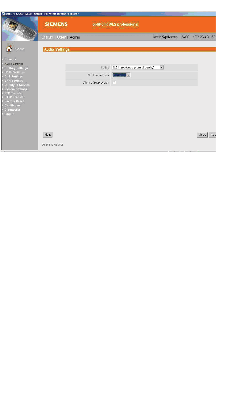
optiPoint WL2 Configuration
hwc_appendixc.fm
optiPoint WL2 wireless telephone configuration
A31003-W1050-U100-2-7619,March 2008
410 HiPath Wireless Controller, Access Points and Convergence Software V5 R1 , C20/C2400 User Guide
To configure Quality of Service protocol settings:
1. In the left pane, click Quality of Service. The Quality of Service: Protocol
Settings page is displayed.
2. Configure the following Quality of Service settings:
•In the DSCP Class for Voice drop-down list, click Expedited
Forwarding to ensure maximum voice priority.
•In the DSCP Class for Signalling drop-down list, click Best Effort.
Under normal conditions Best Effort ensures a more reliable delivery for
Signaling than for Voice (more retries) at the expense of a potential higher
delay.
•In the VLAN Settings section, select None.
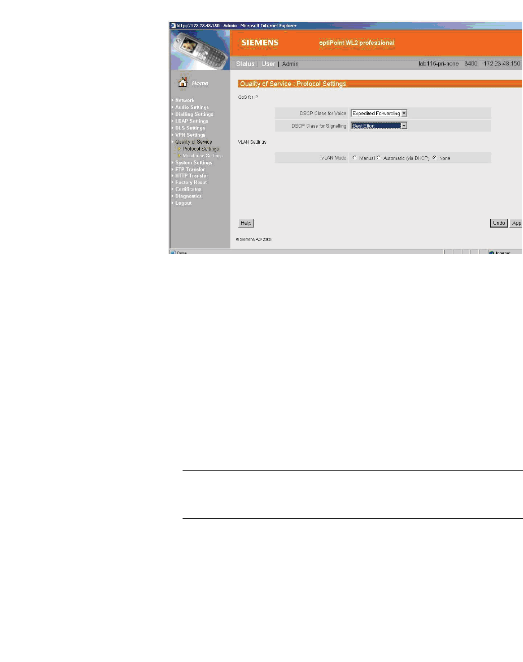
hwc_appendixc.fm
optiPoint WL2 Configuration
optiPoint WL2 wireless telephone configuration
A31003-W1050-U100-2-7619, March 2008
HiPath Wireless Controller, Access Points and Convergence Software V5 R1 , C20/C2400 User Guide 411
To configure WLAN settings:
1. In the left pane, click Network. The Network: Profile Selection page is
displayed.
2. In the List of Profiles, click Edit for the profile you want to configure. The
Network: Profile Name page is displayed.
3. In the left pane, click WLAN. The Network: WLAN for profile page is
displayed.
4. Configure the following WLAN settings:
•In the Output Power (in%) drop-down list, click 100.
Use the maximum 100% unless there is a reason to reduce it.
•In the Transmission Rate drop-down, click Auto.
Note: When the Transmission Rate is set to a value, it does not force the
phone to only use that particular PHY transmission rate. Instead, it forces the
phone to only use PHY rates that are smaller or equal to the set rate.
•In the Fragmentation Threshold box, ensure that the default value 2346
is used.
•In the RTS/CTS Threshold box, ensure that the default value 2347 is
used.
•In the Roaming Threshold box, type a roaming threshold between the
range of -75 dBm to -65 dBm, depending on the parameters of the
deployment.
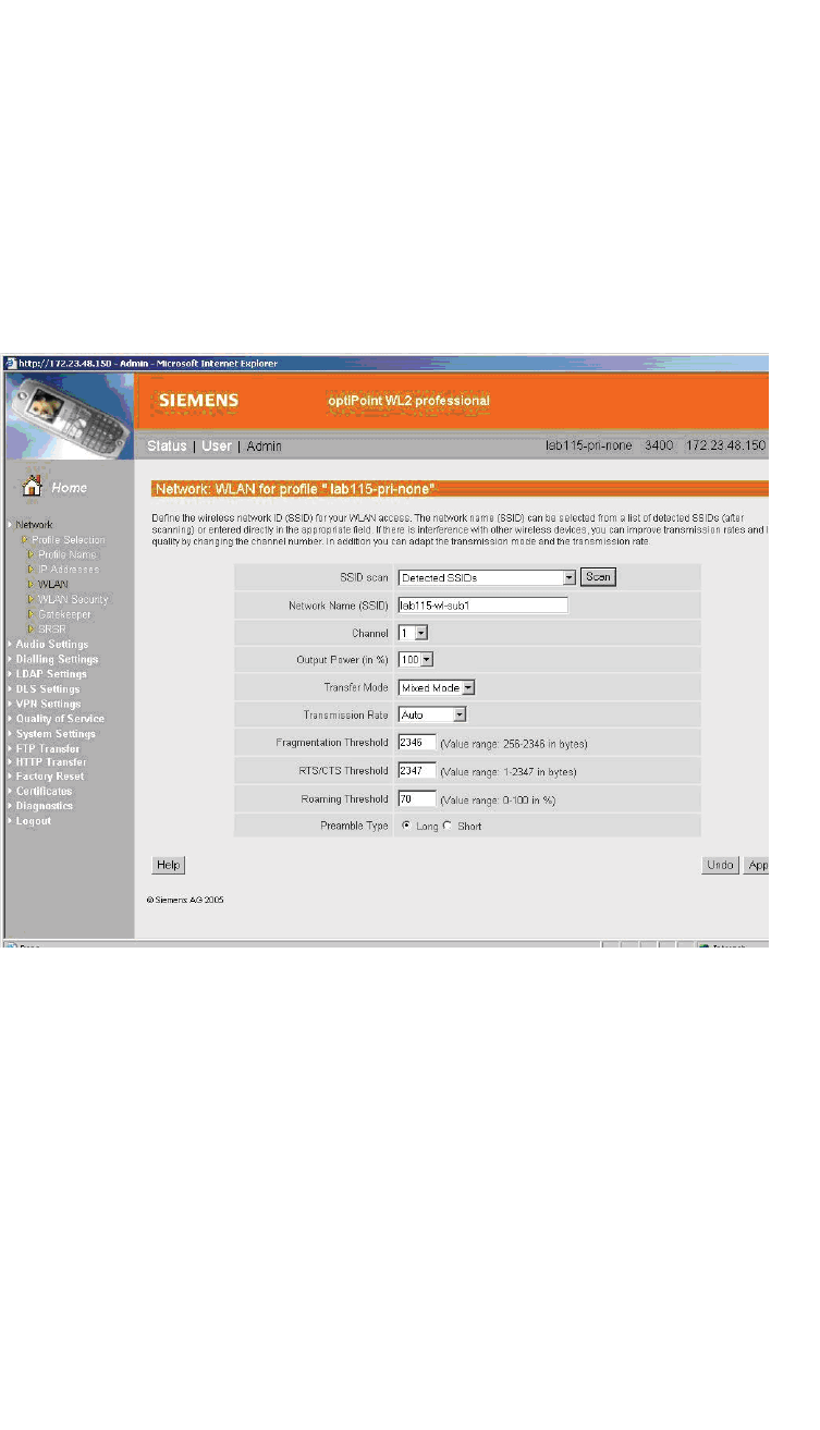
optiPoint WL2 Configuration
hwc_appendixc.fm
optiPoint WL2 wireless telephone configuration
A31003-W1050-U100-2-7619,March 2008
412 HiPath Wireless Controller, Access Points and Convergence Software V5 R1 , C20/C2400 User Guide
A larger value, for example -65 dBm will cause the phone to scan for
alternate Wireless APs more often, which will result in more wireless
traffic and slightly decreased battery life. A smaller value, for example -75
dBm will cause the phone to roam too late, causing voice interruptions
during roaming.
•In the Preamble Type section, select Short. The short preamble provides
for higher voice capacity.
If legacy pre-11b devices are present in the coverage area or you are
unsure if legacy pre-11b devices are present in the coverage area, select
Long.
To configure WLAN security settings:
1. In the left pane, click Network. The Network: Profile Selection page is
displayed.
2. In the left pane, click WLAN Security. The Network: WLAN Security for
profile page is displayed.
3. Configure the following WLAN security settings:
•Click WEP.
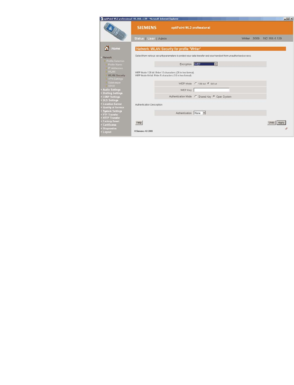
hwc_appendixc.fm
optiPoint WL2 Configuration
HiPath Wireless Controller configuration
A31003-W1050-U100-2-7619, March 2008
HiPath Wireless Controller, Access Points and Convergence Software V5 R1 , C20/C2400 User Guide 413
C.2 HiPath Wireless Controller configuration
The following settings must be configured on the HiPath Wireless Controller.
To configure a VNS topology:
1. From the main menu, click Virtual Network Configuration. The Virtual
Network Configuration page is displayed.
2. Configure the following VNS topology settings:
•A dedicated VNS must be used for WL2 phones. No other non-voice
client should be allowed in this VNS.
•In the Assignment by drop-down list, click SSID. The VNS must be a
non-RADIUS VNS.
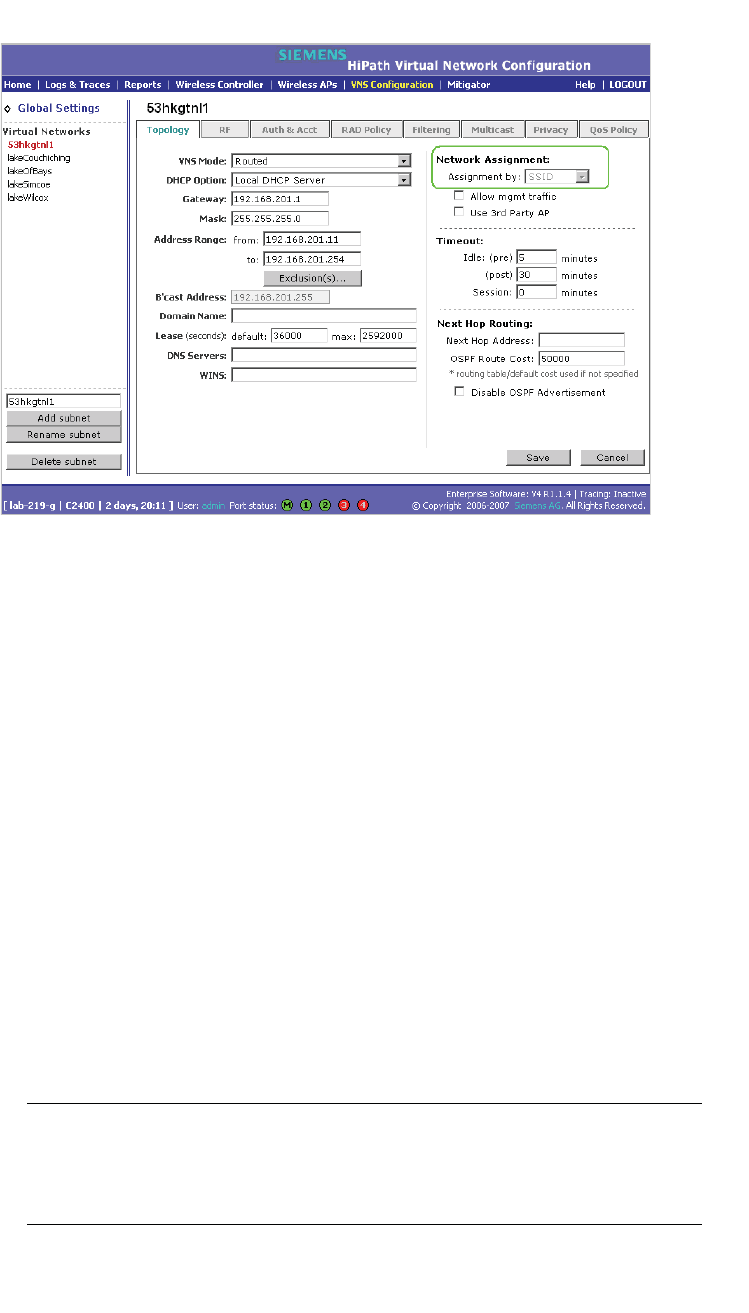
optiPoint WL2 Configuration
hwc_appendixc.fm
HiPath Wireless Controller configuration
A31003-W1050-U100-2-7619,March 2008
414 HiPath Wireless Controller, Access Points and Convergence Software V5 R1 , C20/C2400 User Guide
To configure privacy settings:
1. Click the Privacy tab.
2. Configure the following privacy settings:
•The privacy settings on the HiPath Wireless Controller must match those
on the optiPoint WL2 phone.
•If the optiPoint WL2 phone is configured to use WEP, select the Static
Keys (WEP) option for the VNS.
To configure QoS policy settings:
1. Click the QoS Policy tab.
2. Configure the following QoS policy settings:
•For good voice quality and battery life, select WMM.
•If the VNS is shared with legacy devices that require priority but do not
support WMM, select Legacy.
•If applicable, select 802.11e or Enable U-APSD. (The next release of the
optiPoint WL2 may require .11e support).
Note: The Turbo Voice and Use Global Admission Control for Voice (VO)
options should be cleared. These options should not be used in the same
VNS as the optiPoint WL2. These features are not currently supported on the
optiPoint WL2.
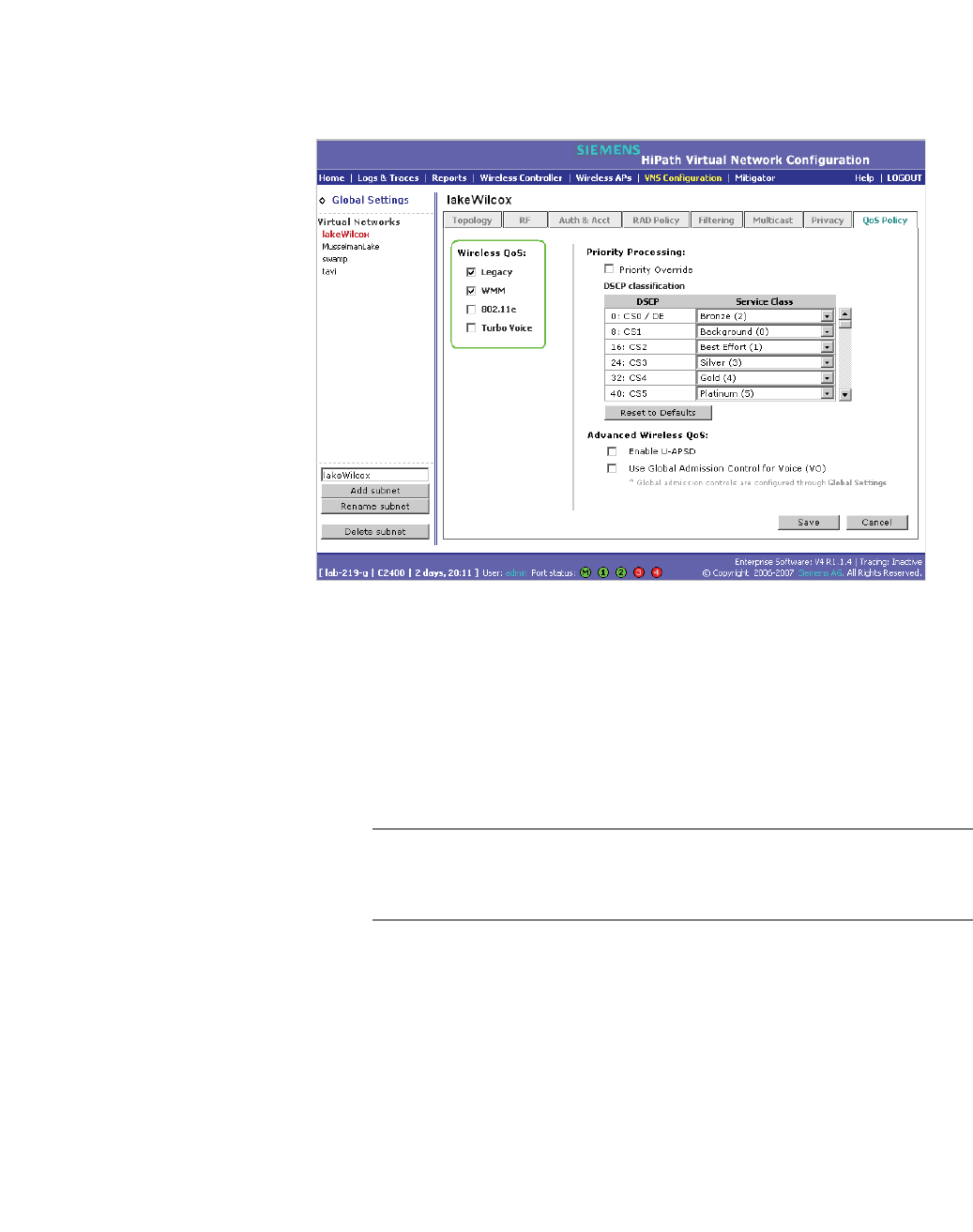
hwc_appendixc.fm
optiPoint WL2 Configuration
HiPath Wireless Controller configuration
A31003-W1050-U100-2-7619, March 2008
HiPath Wireless Controller, Access Points and Convergence Software V5 R1 , C20/C2400 User Guide 415
•The Priority Override option should normally be cleared. If the phone
and PBX are configured properly, the default DSCP classification should
work well. If you are unsure, sniff the packets over the air and check that
the voice packets are sent with priority 6 or 7 in both UL and DL directions.
To configure Wireless AP radio properties:
1. From the main menu, click Wireless AP Configuration. The HiPath
Wireless AP page is displayed.
2. Click the applicable radio tab.
3. Configure the following radio settings:
•In the DTIM Period box, type 5.
Note: ADTIM Period value of 1 may produce better results if significant
RF interference exists in your environment. Use a DTIM Period value of
5 unless you notice a significant improvement when using a value of 1.
•In the Beacon Period box, type 100 (ms).
•In the RTS/CTS Threshold box, ensure that the default value 2346 is
used.
•In the Frag. Threshold box, ensure that the default value 2346 is used.

optiPoint WL2 Configuration
hwc_appendixc.fm
HiPath Wireless Controller configuration
A31003-W1050-U100-2-7619,March 2008
416 HiPath Wireless Controller, Access Points and Convergence Software V5 R1 , C20/C2400 User Guide
•In the Radio Mode drop-down list, click g.
Note: Enable 11b only if 11b devices are used on the same VNS as the
optiPoint WL2 phone.
•In the Rx Diveristy drop-down list, click Best.
•In the Tx Diversity drop-down list, click Best.
Note: If you experience variable or unstable signals, in the Tx Diversity
drop-down list, click Left.
•In the Min Basic Rate drop-down list, click 1Mbps if .11b is enabled.
Note: Use a Min Basic Rate of 6Mbps if you are using only optiPoint
WL2 phones on the VNS, as this will increase the number of concurrent
calls per AP. Use a Min Basic Rate of 2Mbps or 1Mbps if your site has
sparse RF coverage.
•In the Max Basic Rate drop-down list, click the default maximum possible
basic rate. For example, click 11Mbps if you are using using 1 or 2Mbps
as the Min Basic Rate. Otherwise, click 24Mbps.
•In the Max Operational Rate drop-down list, click the default maximum
rate. For example, 54Mbps.
•In the Preamble drop-down list, click Short. The short preamble provides
for higher voice capacity.
If legacy pre-11b devices are present in the coverage area or you are
unsure if legacy pre-11b devices are present in the coverage area, click
Long.
•In the Total # of Tries for Background BK drop-down list, click adaptive
(multi-rate).
•In the Total # of Tries for Best Effort BE drop-down list, click adaptive
(multi-rate).
•In the Total # of Tries for Video VI drop-down list, click adaptive
(multi-rate).
•In the Total # of Tries for Voice VO drop-down list, click adaptive
(multi-rate).
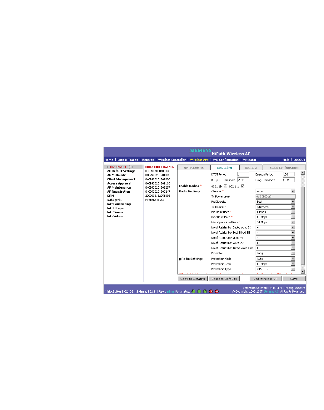
hwc_appendixc.fm
optiPoint WL2 Configuration
HiPath Wireless Controller configuration
A31003-W1050-U100-2-7619, March 2008
HiPath Wireless Controller, Access Points and Convergence Software V5 R1 , C20/C2400 User Guide 417
•In the Total # of Tries for Turbo Voice TVO drop-down list, click
adaptive (multi-rate).
Note: At a minimum, use adaptive (multi-rate) for Total # of Tries for Best
Effort BE and Total # of Tries for Voice VO since this will significantly
improve voice quality.
•In the Protection Mode drop-down list, click Auto.
•In the Protection Rate drop-down list, click 11 Mbps.
•In the Protection Type drop-down list, click CTS. The CTS protection
mode allows for higher voice capacity.
If legacy pre-11b devices are present in the coverage area or you are
unsure if legacy pre-11b devices are present in the coverage area, click
RTS CTS. RTS CTS mode provides more robust protection.

optiPoint WL2 Configuration
hwc_appendixc.fm
HiPath Wireless Controller configuration
A31003-W1050-U100-2-7619,March 2008
418 HiPath Wireless Controller, Access Points and Convergence Software V5 R1 , C20/C2400 User Guide
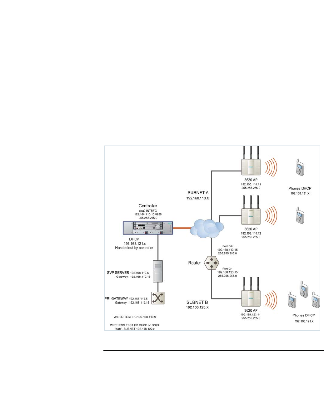
hwc_appendixd.fm
A31003-W1050-U100-2-7619, March 2008
HiPath Wireless Controller, Access Points and Convergence Software V5 R1 , C20/C2400 User Guide 419
SpectraLink Wireless Telephones
Network Topology
D SpectraLink Wireless Telephones
The HiPath Wireless LAN Solution, consisting of the HiPath Wireless Controller,
Wireless APs, and the HiPath Wireless Convergence Software, seamlessly
integrates with SpectraLink Wireless Telephones to serve mobile voice and data
requirements. The standards-based architecture of HiPath Wireless LAN
provides an exceptional infrastructure for voice quality and handset-reliability to
the SpectraLink telephones.
D.1 Network Topology
The following image depicts a typical network topology for SpectraLink
telephones.
Figure 29 SpectraLink Network Topology
Note: The network topology depicted in Figure 29 is a dedicated network for
SpectraLink Telephones. Other topologies are supported and can be used as
required.

SpectraLink Wireless Telephones
hwc_appendixd.fm
Configuring HiPath Wireless Controller for SpectraLink Telephones
A31003-W1050-U100-2-7619,March 2008
420 HiPath Wireless Controller, Access Points and Convergence Software V5 R1 , C20/C2400 User Guide
Note: For a successful deployment, all the network elements in the SpectraLink
network should be provisioned to prioritize voice data.
D.2 Configuring HiPath Wireless Controller for SpectraLink Telephones
This section describes how to configure the HiPath Wireless Controller and
Wireless APs for use with SpectraLink Wireless Telephones.
You have to configure the following features in the HiPath Wireless Controller to
set it up for SpectraLink telephones:
•Radio properties
•SSID
•Filters
•Multicast configuration
•Security
•Quality of Service (QoS)
Note: The configuration process for SpectraLink telephones applies identically to
HiPath Wireless APs, HiPath Wireless Outdoor APs and HiPath Wireless 802.11n
APs, unless specified otherwise.
D.2.1 Setting up SSID
To set up the SSID:
1. From the main menu, click Virtual Network Configuration. The Virtual
Network Configuration screen is displayed.
2. In the left pane, type a name that will identify the new VNS in the Add subnet
box.
3. Click Add subnet. The name is displayed in the Virtual Networks list. The
Topology tab is displayed.
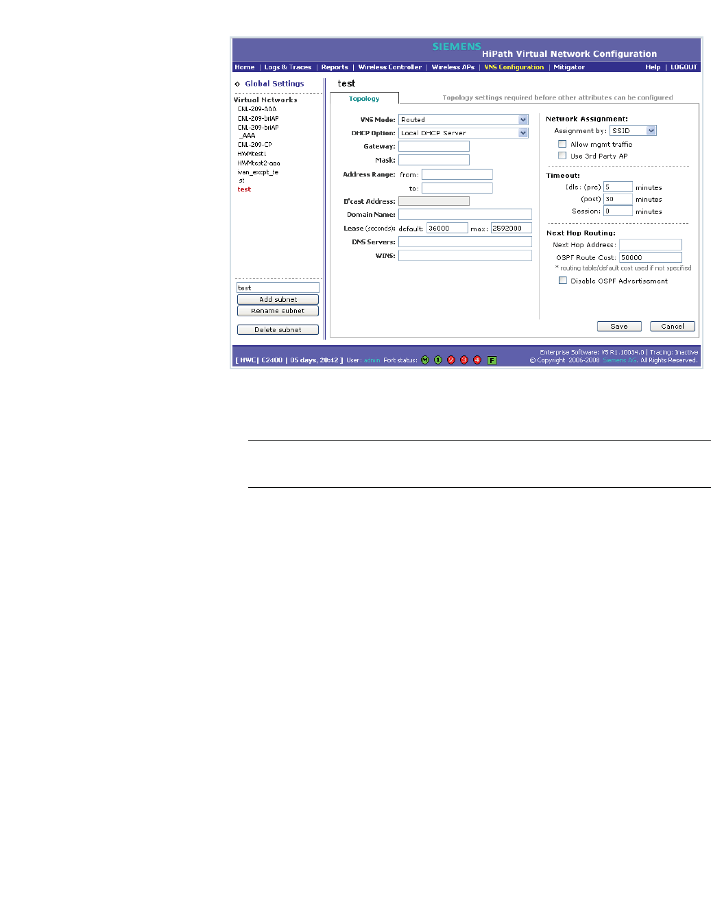
hwc_appendixd.fm
SpectraLink Wireless Telephones
Configuring HiPath Wireless Controller for SpectraLink Telephones
A31003-W1050-U100-2-7619, March 2008
HiPath Wireless Controller, Access Points and Convergence Software V5 R1 , C20/C2400 User Guide 421
4. From the VNS Mode drop-down menu, select appropriate mode after
considering the following details:
Note: It is recommended that you should choose Bridge Traffic Locally at
HWC VNS for SpectraLink network deployment.
5. From the DHCP Option drop-down menu, you can select either the Local
DHCP Server or Use DHCP Relay, depending upon your network topology.
6. In the Gateway box, type the network gateway address.
7. In the Mask box, type the appropriate values.
8. In the Address Range boxes (from and to), type the IP address range.
9. From the Assignment Type drop-down menu, select SSID.
10. Under Timeout section, type 2 in the pre and post boxes.
11. Under Next Hop Routing section, type 50000 in the OSPF Route Cost box.
12. Click Save.
D.2.2 Configuring filters
To configure the filters:
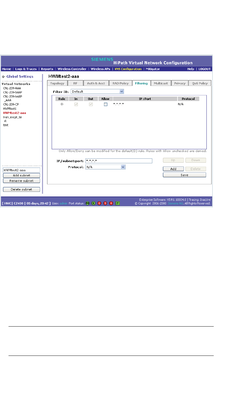
SpectraLink Wireless Telephones
hwc_appendixd.fm
Configuring HiPath Wireless Controller for SpectraLink Telephones
A31003-W1050-U100-2-7619,March 2008
422 HiPath Wireless Controller, Access Points and Convergence Software V5 R1 , C20/C2400 User Guide
1. From the main menu, click Virtual Network Configuration. The Virtual
Network Configuration screen is displayed.
2. On the Virtual Network Configuration screen, click the Filtering tab. The
filtering rule for the Default filter is displayed in the centre pane.
3. Type the IP address of SVP server in IP/Subnet:port box.
4. From the Protocol drop-down menu, select UDP.
5. Click Add. The new filtering rule for the SVP server is displayed in the centre
pane.
6. Click Up. The filtering rule for the SVP server moves up, before the filter rule
for Default filter.
7. Type the IP address of SpectraLink Gateway in IP/Subnet:port box, and then
repeat steps 4 to 6.
8. Add the filtering rules for the IP addresses of all network elements as
explained in steps 3 to 6.
Note: You must ensure that all the filtering rules, including the ones for SVP/
Gateway and other network elements, are moved up, before the filtering rule
for the Default filter.
9. Select the Allow option of the Default filter.
10. Click Save.
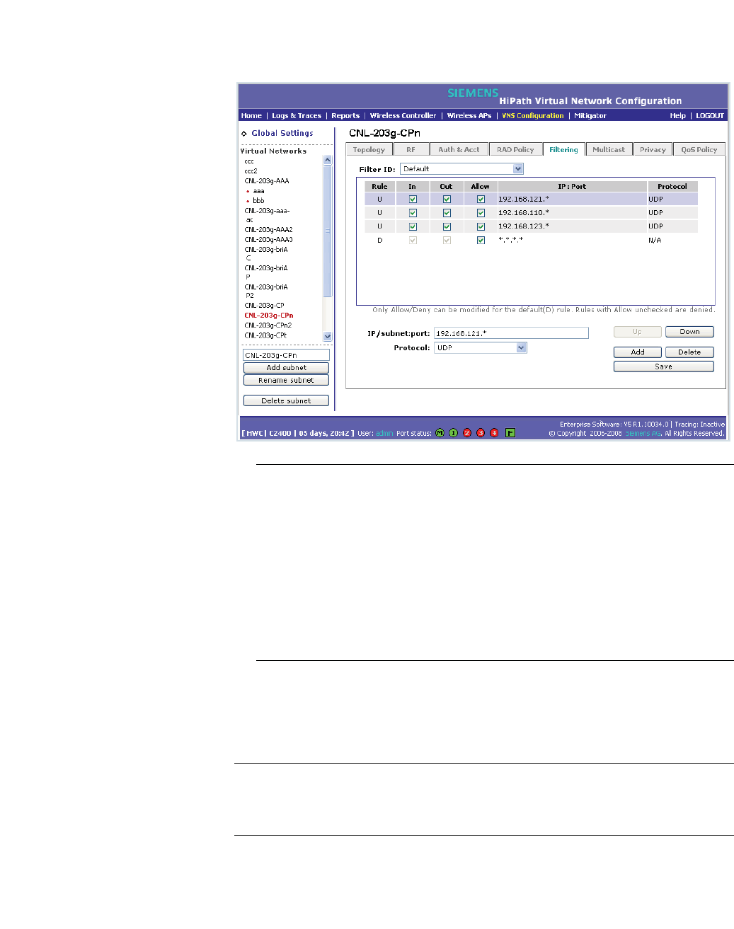
hwc_appendixd.fm
SpectraLink Wireless Telephones
Configuring HiPath Wireless Controller for SpectraLink Telephones
A31003-W1050-U100-2-7619, March 2008
HiPath Wireless Controller, Access Points and Convergence Software V5 R1 , C20/C2400 User Guide 423
The following screen-shot depicts how the configuration will appear in context
of the network topology illustrated in Figure 29 on page 419.
Note: You must complete the remaining configuration as explained in the
subsequent sections, and then check if the deployment is working properly. If
the deployment is working properly, you should deselect Allow option of the
Default filter in order to secure the network
The secure setup in context of the network topology illustrated in Figure 29
on page 419 will be as follows:
• Allow 192.168.121.* UDP
• Allow 192.168.110.* UDP
• Allow 192.168.123.* UDP
• Disallow *.*.*.* N/A T
D.2.3 Setting up Multicast configuration
Note: Before you set up multicast configuration, you must specify the physical
port for routing multicast traffic on the Wireless Controller configuration screen
(Wireless Controller Configuration>IP addresses>.
To set up multicast configuration:
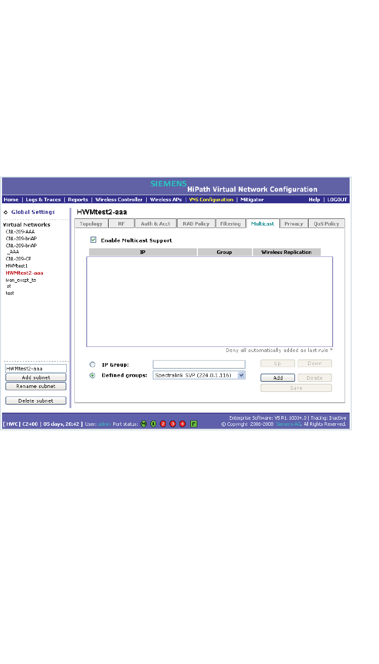
SpectraLink Wireless Telephones
hwc_appendixd.fm
Configuring HiPath Wireless Controller for SpectraLink Telephones
A31003-W1050-U100-2-7619,March 2008
424 HiPath Wireless Controller, Access Points and Convergence Software V5 R1 , C20/C2400 User Guide
1. From the main menu, click Virtual Network Configuration. The Virtual
Network Configuration screen is displayed.
2. On the Virtual Network Configuration screen, click the Multicast tab.
3. Select Enable Multicast Support.
4. From the Defined groups drop-down list, select Spectralink SVP
(224.0.1.116) and then click Add.
5. Select Wireless Replication checkbox.
6. Click Save button.
D.2.4 Setting up Security
To set up the security:
1. From the main menu, click Virtual Network Configuration. The Virtual
Network Configuration screen is displayed.
2. On the Virtual Network Configuration screen, click the Privacy tab.
3. Select the WPA-PSK radio button.
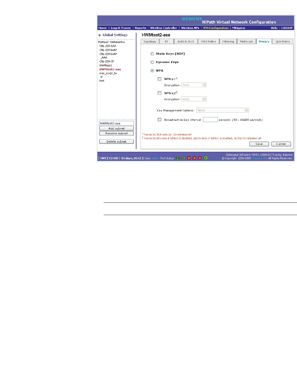
hwc_appendixd.fm
SpectraLink Wireless Telephones
Configuring HiPath Wireless Controller for SpectraLink Telephones
A31003-W1050-U100-2-7619, March 2008
HiPath Wireless Controller, Access Points and Convergence Software V5 R1 , C20/C2400 User Guide 425
4. Select the WPA v.2 radio button.
5. Under WPA v.2 section, select AES only from the Encryption drop-down
menu.
Note: The SpectraLinke telephones must also be for WPA v.2 security.
6. Enter the appropriate pass phrase in the Pre-shared key field.
7. Click Save.
D.2.5 Setting up Quality of Service (QoS)
To set up Quality of Service (QoS):
1. From the main menu, click Virtual Network Configuration. The Virtual
Network Configuration screen is displayed.
2. On the Virtual Network Configuration screen, click the QoS Policy tab.
3. Under the Wireless QoS section, select the following:
•Legacy
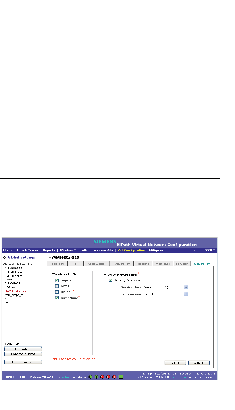
SpectraLink Wireless Telephones
hwc_appendixd.fm
Configuring HiPath Wireless Controller for SpectraLink Telephones
A31003-W1050-U100-2-7619,March 2008
426 HiPath Wireless Controller, Access Points and Convergence Software V5 R1 , C20/C2400 User Guide
•Turbo Voice
Note: If you are using HiPath Wireless APs and HiPath Wireless Outdoor APs,
you must ensure that Turbo Voice QoS is selected to achieve best voice quality
with the SpectraLink telephones.
Turbo Voice QoS does not have any effect on HiPath Wireless 802.11n APs as
these APs provide best voice quality regardless of whether Turbo Voice QoS is
selected or not.
Note: To achieve “higher call capacity”, you must ensure that WMM QoS is
deselected.
Note: The HiPath Wireless 802.11n APs supports only the WMM QoS. If you are
using 802.11n APs, and you want to achieve “higher call capacity”, you must
ensure that WMM QoS is deselected.
The Legacy,802.11e, and Turbo Voice QoSs do not have any effect on the
802.11n APs regardless of whether these QoSs are selected or not.
4. Under the Priority Processing section, select Priority Override.
5. Retain the default value in Service Class drop-down menu.
6. Retain the default value in DSCP marking drop-down menu.
7. Click Save.

hwc_appendixd.fm
SpectraLink Wireless Telephones
Configuring HiPath Wireless Controller for SpectraLink Telephones
A31003-W1050-U100-2-7619, March 2008
HiPath Wireless Controller, Access Points and Convergence Software V5 R1 , C20/C2400 User Guide 427
D.2.6 Setting up Radio Properties
To set up the radio for Voice Wireless LAN in HiPath Wireless AP (Models
2610/2620):
1. From the main menu, click Wireless AP Configuration. The Wireless AP
Configuration screen is displayed.
2. From the list of Wireless APs, select the Wireless AP that is being used for
the Voice WLAN.
3. On the Wireless AP Configuration screen, click 802.11b/g or 802.11a/g,
depending upon the radio that is being used for Voice WLAN.
4. Under Base Settings, set the DTIM Period to 3:
5. Under Basic Radio Settings, set the following parameters:
• Tx Diversity: Set the Tx Diversity to either Left or Right.
• Total # of retries for Voice VO: Set the Total # of retries for Voice VO
to adaptive (multi-rate).
Note: It is recommended that the Tx Diversity should be set to Left.
6. Retain the default values for all other parameters.
7. Click Save.
To set up the radio for Voice Wireless LAN in HiPath Wireless 802.11n APs
(Models AP3610/3620):
1. From the main menu, click Wireless AP Configuration. The Wireless AP
Configuration screen is displayed.
2. From the list of Wireless APs, select the Wireless 802.11n AP that is being
used for the Voice WLAN.
3. On the Wireless AP Configuration screen, click 802.11b/g/n or 802.11a/g/
n, depending upon the radio that is being used for Voice WLAN.
4. Under Base Settings, set the DTIM Period to 3.
5. Retain the default values for all other parameters.
6. Click Save.

SpectraLink Wireless Telephones
hwc_appendixd.fm
Configuring HiPath Wireless Controller for SpectraLink Telephones
A31003-W1050-U100-2-7619,March 2008
428 HiPath Wireless Controller, Access Points and Convergence Software V5 R1 , C20/C2400 User Guide

hwc_user_guideIX.fm
A31003-W1050-U100-2-7619, March 2008
HiPath Wireless Controller, Access Points and Convergence Software V5 R1 ,C20/C2400 User Guide 429
Nur für den internen Gebrauch Index
Index Z
A
accounting
setup on a VNS 191
ACS - Automatic Channel Selection 95
adding
Wireless AP manually 87
alarms
overview of log types and levels 342
allow all or approved APs
for availability setup 254
allow or deny in a filtering rule 154
Analysis engine
functions 286
ATPC - Auto Tx Power Control 96
authentication
MAC-based 189
no RADIUS server 149
none on a VNS 218
on a VNS for AAA 186
on a VNS for Captive Portal 178
overview of types 176
protocols supported 152, 181
Authentication, Authorization, Accounting (AAA)
set up 802.1x authentication 186
set up privacy on a VNS 211
availability 254
B
back panel, HiPath Wireless Controller C2400 375
backup controller configuration 333, 335
branch office, static configuration of Wireless AP 114
C
call data records (CDRs) 191
Captive Portal
authentication on a VNS 178
configuring internal, external Captive Portal 184
defined 152
non-authenticated filtering rules 197
privacy mechanisms 208
set up a VNS topology 165
view sample page 185
Check Point event logging 268
codes, LED states and seven segment display 373
configuring
Captive Portal, internal, external 184
software - overview steps 30
static routes 47
controller
availability overview 29
backup configuration 333
scheduling 335
define management user names, passwords 264
define network time synchronization 266
defined as mobility manager for mobility 259
enable ELA event logging (Check Point) 268
events during a failover 257
paired for availability 251
restore database 337
set up third-party APs 277
system maintenance 317
system shutdown 317
uploading backup configuration 334
D
default filter 203
default gateway on a VNS 170
disassociate a wireless client 309
discovery
steps 72
Wireless AP LED sequence 74
displays
client location by foreign HWC 264, 300
client location by home 264, 300
HWC tunnel traffic 264, 300
list of displays 293
Wireless AP availability 256, 295
Wireless AP wired and wireless statistics 295
documentation feedback 11
Domain Name Server (DNS)
in discovery 72
DRM - Dynamic Radio Management 95
DSCP classifications 224
Dynamic Host Configuration Protocol (DHCP)
for availability 251
for mobility (VN Manager) 259
Option 78 in discovery 72
relay on a VNS 172
required as part of solution 19
E
event logging
in Check Point 268
in HWC software 342
exception filters
on a VNS 195
port-based 54
exclusions, IP address range on a VNS 170

Index Nur für den internen Gebrauch
A31003-W1050-U100-2-7619, March 2008
430 HiPath Wireless Controller, Access Points and Convergence Software V5 R1 , C20/C2400 User Guide
hwc_user_guideIX.fm
F
failover of a controller
availability overview 29
events and recovery 257
failover of a RADIUS server 181
filtering
default filter 203
exception filter on a VNS 195
filtering rules, overview of set up 194
for an AAA group 205
for Captive Portal authentication 185
non-authenticated filter for Captive Portal 197
non-authenticated filtering rules, examples 200
on a VNS for third-party APs 280
overview of packet filtering 28
overview, four types 154
port-based 52
rules for filter ID values 201
set filter ID values (RADIUS policy) 193
formatting conventions 10
forwarding table report 48
front panel, HiPath Wireless Controller C2400 371
G
gateway, default, on a VNS 170
global settings
for a VNS 157
RADIUS servers for authentication 179, 187, 190,
192
H
health checking status of Wireless APs 317
heartbeat messages, in VN Manager feature 259
HiPath Wireless Controller C2400 back panel 375
HiPath Wireless Controller C2400 front panel 371
HiPath Wireless Manager 22, 90, 341
shared secret configuration 341
HiPath Wireless Manager Advanced (HWMA) 141
I
IP address range on a VNS 170
K
key management options
none 215
opportunistic keying 215
opportunistic keying & pre-auth 216
pre-authentication 215
L
LED sequence
in discovery 74
LED states and seven segment display (SSD) codes
373
login user name and password 37
Login-LAT-Group 201
logs
changing log level 317
event logging in Check Point 268
overview of types and levels 342
M
MAC-based authentication 189
Management Information Bases (MIBs) supported
271
management port
management traffic on data port 46
modify management port settings 39
port-based filtering 52
management traffic
enabling on a VNS 168
mobility
mobility manager and mobility agent 259
overview 29
mobility manager
defining a controller for mobility 259
multicast
for a VNS 206
N
network assignment
by AAA 211
by SSID for Captive Portal 165
options for a VNS 150
VLAN 21, 25
network security, overview 25
network time synchronization 266
next hop route for a VNS 169
non-authenticated filter for Captive Portal 185, 197
ntrol 96
O
OSPF
configuring 49
linkstate report 52
neighbor report 52
on a VNS 169
overview 27
P
password, for management users 264
port
port exception filters 54
priority override 220
privacy
dynamic WEP on a VNS for AAA 213

hwc_user_guideIX.fm
A31003-W1050-U100-2-7619, March 2008
HiPath Wireless Controller, Access Points and Convergence Software V5 R1 ,C20/C2400 User Guide 431
Nur für den internen Gebrauch Index
encryption methods supported 25
on a VNS for AAA
AAA 211
overview on a VNS 156
setup on a VNS for Captive Portal 208
static WEP for an AAA VNS 212
WPA v1 and WPA v2 on a VNS for AAA 213
protocols
for authentication by Captive Portal 181
Q
QoS (Quality of Service) 30, 150, 159, 160, 219, 220,
363, 366
admission control thresholds 159
advanced 224
modes 221
policy 223
R
radio
channels 98, 106, 114
radio settings
view and modify 95
RADIUS server
deployment with no server 149
filter ID values 201
for authentication 179, 187, 190, 192
for MAC-based authentication 189
priority for redundancy 181
RADIUS accounting 191
RADIUS policy for a VNS 193
required as part of solution 19
VSAs in RADIUS message 177
read/write privileges 264
reboot Wireless AP 142
registration
settings for availability setup 254
reports
AP inventory 303
forwarding table 48, 303
list of displays 293
OSPF linkstate 52, 303
OSPF neighbor 52, 303
restore controller database 337
rogue detection, Mitigator feature 287
routing
configuring OSPF on data port 49
configuring static routes 47
next hop route on a VNS 169
overview 28
routing table
viewing 48
S
scan results, Mitigator feature 287
service class 219
Service Location Protocol (SLP)
for availability 251
for mobility (VN Manager) 259
in discovery 72
required as part of solution 19
traffic allowed on data port 46
view slpdump tool report 257
set up for a VNS 277
shut down system 317
Simple Network Management Protocol (SNMP)
MIBs supported 271
publish AP as interface of controller 273
software
maintenance 320
scheduled upgrade 332
upgrade 324
maintenance of Wireless AP software 142
SSID network assignment for Captive Portal 165
static configuration of Wireless AP 114
static routes
configuring 47
viewing forwarding table report 48
syslog event reporting
define parameters 317
T
third-party APs 277
defining a VNS for 168
topology of a VNS
Captive Portal 165
traces
overview of log types and levels 342
Type of Service (ToS/DSCP)
on a VNS 219
Quality of Service 30
U
user name and password for login 37
user name and password, changing 264
V
vendor specific attributes (VSA)
in RADIUS message 177
RADIUS server
vendor specific attributes 181, 188
Virtual Network Services 27
Virtual Network Services (VNS)
authentication by AAA (802.1x) 186
authentication by Captive Portal 178

Index Nur für den internen Gebrauch
A31003-W1050-U100-2-7619, March 2008
432 HiPath Wireless Controller, Access Points and Convergence Software V5 R1 , C20/C2400 User Guide
hwc_user_guideIX.fm
define filtering rules 194
defined 147
for third-party APs 278
global settings 157
multicast 206
network assignment overview 150
privacy for AAA 211
privacy overview 208
set up for VoIP 219
topology for Captive Portal 165
VLAN 366
configuration 115, 116, 163, 170, 220, 226, 228
IDs 228, 229
Voice-over-IP (VoIP)
define multicast groups on a VNS 206
set up a VNS for 219
W
WDS
deployment 238
examples of deployment 231
key features 234
overview 229
simple configuration 229
vns 231
wireless bridge configuration 231
wireless repeater configuration 230
WDS - Wireless Distribution System 229
Wi-Fi Multimedia (WMM)
on a VNS 219
Quality of Service 30
Wi-Fi Protected Access (WPA)
overview on a VNS 156
PSK mode for Captive Portal 209
WPA v1 and v2 on a VNS for AAA 213
Wired Equivalent Privacy (WEP)
on a VNS for AAA 212
overview on a VNS 156
static for Captive Portal 208
Wireless AP
802.1x 117
credentials 123
EAP-TLS 118, 120
multi-edit 125
PEAP 118, 119
adding for availability setup 254
adding manually 87
assigning to a VNS 175
client disassociate 309
default configuration 36, 74, 128, 138, 139, 254,
258
copy to defaults 139
DRM 95
factory defaults 313
international licensing 65
LED sequence in discovery 74
maintenance and reboot 142
radios 95
reset button 315
sensor 22, 26, 90, 93, 96, 128, 141, 143
sensor management 142
static configuration 114
view statistics 295