Siemens Communications AP36V1B HiPath Wireless Access Point, Altitude 450, Altitude 451 User Manual User s Guide
Siemens Communications, Inc. HiPath Wireless Access Point, Altitude 450, Altitude 451 User s Guide
Contents
User's Guide

Communication for the open minded
Siemens Enterprise Communications
www.siemens.com/open
Documentation
HiPath Wireless Controller, Access Points and
Convergence Software V7.11
User Guide
9034530-02

Copyright ©
Siemens Enterprise
Communications GmbH & Co. KG 2010
Hofmannstr. 51, 80200 München
Siemens Enterprise Communications GmbH & Co. KG
is
a Trademark Licensee of Siemens AG
Reference No.: 9034530-02-01
The information provided in this document contains
merely general descriptions or characteristics of
performance which in case of actual use do not always
apply as described or which may change as a result of fur-
ther development of the products. An obligation to pro-
vide the respective characteristics shall only exist if ex-
pressly agreed in the terms of contract. Availability and
technical specifications are subject to change without no-
tice.
OpenScape, OpenStage and HiPath are registered trade-
marks of Siemens Enterprise
Communications GmbH & Co. KG.
All other company, brand, product and service names are
trademarks or registered trademarks of their respective
holders.
Siemens Enterprise Communications
www.siemens.com/open
Communication for the open minded

hwc_pref.fm
9034530-02, March 2010
HiPath Wireless Controller, Access Points and Convergence Software V7.11, User Guide 3
About this Guide
Who should use this guide
1 About this Guide
This guide describes how to install, configure, and manage the HiPath Wireless
Controller, Access Points and Convergence Software system. This guide is also
available as an online help system.
To access the online help system:
1. In the HiPath Wireless Assistant Main Menu bar, click Help. The About
HiPath Wireless Assistant screen is displayed.
2. In the left pane, click Controller Documentation. The online help system is
launched.
1.1 Who should use this guide
This guide is a reference for system administrators who install and manage the
HiPath Wireless Controller, Access Points and Convergence Software system.
Any administrator performing tasks described in this guide must have an account
with administrative privileges.
1.2 What is in this guide
This guide contains the following:
•Chapter 1, “About this Guide”, describes the target audience and content of
the guide, the formatting conventions used in it, and how to provide feedback
on the guide.
•Chapter 2, “Overview of the HiPath Wireless Controller, Access Points and
Convergence Software solution”, provides an overview of the product, its
features and functionality.
•Chapter 3, “Configuring the HiPath Wireless Controller”, describes how to
perform the installation, first time setup and configuration of the HiPath
Wireless Controller, as well as configuring the data ports and defining routing.
•Chapter 4, “Configuring the Wireless AP”, describes how to install the
Wireless AP, how it discovers and registers with the HiPath Wireless
Controller, and how to view and modify radio configuration.
•Chapter 5, “Virtual Network Services concepts”, provides an overview of
Virtual Network Services (VNS), the mechanism by which the HiPath
Wireless Controller, Access Points and Convergence Software controls and
manages network access.

About this Guide
hwc_pref.fm
Formatting conventions
9034530-02, March 2010
4HiPath Wireless Controller, Access Points and Convergence Software V7.11, User Guide
•Chapter 6, “Configuring a VNS”, provides detailed instructions in how to
configure a VNS, either using the Wizards or by manually creating the
component parts of a VNS.
•Chapter 7, “Availability and session availability”, describes how to set up the
features that maintain service availability in the event of a HiPath Wireless
Controller failover.
•Chapter 8, “Configuring Mobility”, describes how to set up the mobility domain
that provides mobility for a wireless device user when the user roams from
one Wireless AP to another in the mobility domain.
•Chapter 9, “Working with third-party APs”, describes how to use the
Controller, Access Points and Convergence Software features with third-
party wireless access points.
•Chapter 10, “Working with the Mitigator”, describes the security tool that
scans for, detects, and reports on rogue APs.
•Chapter 11, “Working with reports and displays”, describes the various
reports and displays available in the HiPath Wireless Controller, Access
Points and Convergence Software system.
•Chapter 12, “Performing system administration”, describes system
administration activities, such as performing Wireless AP client management,
defining management users, configuring the network time, and configuring
Web session timeouts.
•Chapter 13, “Glossary”, contains a list of terms and definitions for the HiPath
Wireless Controller and the Wireless AP as well as standard industry terms
used in this guide.
•Appendix A, describes the physical description and LED states of the HiPath
Wireless Controller.
•Appendix B, provides the regulatory information for the HiPath Wireless
Controller and the HiPath Wireless Access Points (APs).
•Appendix C, describes how to configure the WL2 phone.
•Appendix D, describes how to configure NetLink Wireless Telephones and
WLAN infrastructure products.
•Appendix E, provides the default GuestPortal ticket page source code.
1.3 Formatting conventions
The HiPath Wireless Controller, Access Points and Convergence Software
documentation uses the following formatting conventions to make it easier to find
information and follow procedures:

hwc_pref.fm
About this Guide
Additional documentation
9034530-02, March 2010
HiPath Wireless Controller, Access Points and Convergence Software V7.11, User Guide 5
•Bold text is used to identify components of the management interface, such
as menu items and section of pages, as well as the names of buttons and text
boxes.
For example: Click Logout.
•Monospace font is used in code examples and to indicate text that you type.
For example: Type https://<hwc-address>[:mgmt-port>]
•The following notes are used to draw your attention to additional information:
Note: Notes identify useful information, such as reminders, tips, or other ways to
perform a task.
Caution: Cautionary notes identify essential information, which if ignored can
adversely affect the operation of your equipment or software.
Warning: Warning notes identify essential information, which if ignored can lead
to personal injury or harm.
1.4 Additional documentation
For additional HiPath Wireless documentation, see the HiPath Wireless
documentation at
http://www.enterasys.com/support/manuals
1.5 Getting Help
For additional support related to the product or this document, contact Enterasys
Networks using one of the following methods:
World Wide Web www.enterasys.com/support
Phone 1-800-872-8440 (toll-free in U.S. and Canada)
or 1-978-684-1000
To find the Enterasys Networks Support toll-free number in your
country: www.enterasys.com/support
Internet mail support@enterasys.com
To expedite your message, type HiPath Wireless in the subject line

About this Guide
hwc_pref.fm
Safety Information
9034530-02, March 2010
6HiPath Wireless Controller, Access Points and Convergence Software V7.11, User Guide
Before contacting Enterasys Networks for technical support, have the following
information ready:
•Your Enterasys Networks service contract number
•A description of the failure
•A description of any action(s) already taken to resolve the problem (for
example, changing mode switches or rebooting the unit)
•The serial and revision numbers of all involved Enterasys Networks products
in the network
•A description of your network environment (such as layout, cable type, other
relevant environmental information)
•Network load and frame size at the time of trouble (if known)
•The device history (for example, if you have returned the device before, or if
this a recurring problem)
•Any previous Return Material Authorization (RMA) numbers
1.6 Safety Information
Dangers
•Replace the power cable immediately if it shows any sign of damage.
•Replace any damaged safety equipment (covers, labels and protective
cables) immediately.
•Use only original accessories or components approved for the system.
Failure to observe these instructions may damage the equipment or even
violate safety and EMC regulations.
•Only authorized Siemens service personnel are permitted to service the
system.
Warnings
•This device must not be connected to a LAN segment with outdoor wiring.
•Ensure that all cables are run correctly to avoid strain.
•Replace the power supply adapter immediately if it shows any sign of
damage.
To send comments concerning this document to the Technical Publications Department:
techpubs@enterasys.com
Please include the document part number in your email message.

hwc_pref.fm
About this Guide
Sicherheitshinweise
9034530-02, March 2010
HiPath Wireless Controller, Access Points and Convergence Software V7.11, User Guide 7
•Disconnect all power before working near power supplies unless otherwise
instructed by a maintenance procedure.
•Exercise caution when servicing hot swappable HiPath Wireless Controller
components: power supplies or fans. Rotating fans can cause serious
personal injury.
•This unit may have more than one power supply cord. To avoid electrical
shock, disconnect all power supply cords before servicing. In the case of unit
failure of one of the power supply modules, the module can be replaced
without interruption of power to the HiPath Wireless Controller. However, this
procedure must be carried out with caution. Wear gloves to avoid contact with
the module, which will be extremely hot.
•There is a risk of explosion if a lithium battery is not correctly replaced. The
lithium battery must be replaced only by an identical battery or one
recommended by the manufacturer.
•Always dispose of lithium batteries properly.
•Do not attempt to lift objects that you think are too heavy for you.
Cautions
•Check the nominal voltage set for the equipment (operating instructions and
type plate). High voltages capable of causing shock are used in this
equipment. Exercise caution when measuring high voltages and when
servicing cards, panels, and boards while the system is powered on.
•Only use tools and equipment that are in perfect condition. Do not use
equipment with visible damage.
•To protect electrostatic sensitive devices (ESD), wear a wristband before
carrying out any work on hardware.
•Lay cables so as to prevent any risk of them being damaged or causing
accidents, such as tripping.
1.7 Sicherheitshinweise
Gefahrenhinweise
•Sollte das Netzkabel Anzeichen von Beschädigungen aufweisen, tauschen
Sie es sofort aus.
•Tauschen Sie beschädigte Sicherheitsausrüstungen (Abdeckungen,
Typenschilder und Schutzkabel) sofort aus.

About this Guide
hwc_pref.fm
Sicherheitshinweise
9034530-02, March 2010
8HiPath Wireless Controller, Access Points and Convergence Software V7.11, User Guide
•Verwenden Sie ausschließlich Originalzubehör oder systemspezifisch
zugelassene Komponenten. Die Nichtbeachtung dieser Hinweise kann zur
Beschädigung der Ausrüstung oder zur Verletzung von Sicherheits- und
EMV-Vorschriften führen.
•Das System darf nur von autorisiertem Siemens-Servicepersonal gewartet
werden.
Warnhinweise
•Dieses Gerät darf nicht über Außenverdrahtung an ein LAN-Segment
angeschlossen werden.
•Stellen Sie sicher, dass alle Kabel korrekt geführt werden, um Zugbelastung
zu vermeiden.
•Sollte das Netzteil Anzeichen von Beschädigung aufweisen, tauschen Sie es
sofort aus.
•Trennen Sie alle Stromverbindungen, bevor Sie Arbeiten im Bereich der
Stromversorgung vornehmen, sofern dies nicht für eine Wartungsprozedur
anders verlangt wird.
•Gehen Sie vorsichtig vor, wenn Sie an Hotswap-fähigen HiPath Wireless
Controller-Komponenten (Stromversorgungen oder Lüftern) Servicearbeiten
durchführen. Rotierende Lüfter können ernsthafte Verletzungen
verursachen.
•Dieses Gerät ist möglicherweise über mehr als ein Netzkabel angeschlossen.
Um die Gefahr eines elektrischen Schlages zu vermeiden, sollten Sie vor
Durchführung von Servicearbeiten alle Netzkabel trennen. Falls eines der
Stromversorgungsmodule ausfällt, kann es ausgetauscht werden, ohne die
Stromversorgung zum HiPath Wireless Controller zu unterbrechen. Bei
dieser Prozedur ist jedoch mit Vorsicht vorzugehen. Das Modul kann extrem
heiß sein. Tragen Sie Handschuhe, um Verbrennungen zu vermeiden.
•Bei unsachgemäßem Austausch der Lithium-Batterie besteht
Explosionsgefahr. Die Lithium-Batterie darf nur durch identische oder vom
Händler empfohlene Typen ersetzt werden.
•Achten Sie bei Lithium-Batterien auf die ordnungsgemäße Entsorgung.
•Versuchen Sie niemals, ohne Hilfe schwere Gegenstände zu heben.
Vorsichtshinweise
•Überprüfen Sie die für die Ausrüstung festgelegte Nennspannung
(Bedienungsanleitung und Typenschild). Diese Ausrüstung arbeitet mit
Hochspannung, die mit der Gefahr eines elektrischen Schlages verbunden
ist. Gehen Sie mit großer Vorsicht vor, wenn Sie bei eingeschaltetem System
Hochspannungen messen oder Karten, Schalttafeln und Baugruppen warten.

hwc_pref.fm
About this Guide
Consignes de sécurité
9034530-02, March 2010
HiPath Wireless Controller, Access Points and Convergence Software V7.11, User Guide 9
•Verwenden Sie nur Werkzeuge und Ausrüstung in einwandfreiem Zustand.
Verwenden Sie keine Ausrüstung mit sichtbaren Beschädigungen.
•Tragen Sie bei Arbeiten an Hardwarekomponenten ein Armband, um
elektrostatisch gefährdete Bauelemente (EGB) vor Beschädigungen zu
schützen.
•Verlegen Sie Leitungen so, dass sie keine Unfallquelle (Stolpergefahr) bilden
und nicht beschädigt werden.
1.8 Consignes de sécurité
Dangers
•Si le cordon de raccordement au secteur est endommagé, remplacez-le
immédiatement.
•Remplacez sans délai les équipements de sécurité endommagés (caches,
étiquettes et conducteurs de protection).
•Utilisez uniquement les accessoires d'origine ou les modules agréés
spécifiques au système. Dans le cas contraire, vous risquez d'endommager
l'installation ou d'enfreindre les consignes en matière de sécurité et de
compatibilité électromagnétique.
•Seul le personnel de service Siemens est autorisé à maintenir/réparer le
système.
Avertissements
•Cet appareil ne doit pas être connecté à un segment de LAN à l'aide d'un
câblage extérieur.
•Vérifiez que tous les câbles fonctionnent correctement pour éviter une
contrainte excessive.
•Si l'adaptateur d'alimentation présente des dommages, remplacez-le
immédiatement.
•Coupez toujours l'alimentation avant de travailler sur les alimentations
électriques, sauf si la procédure de maintenance mentionne le contraire.
•Prenez toutes les précautions nécessaires lors de l'entretien/réparations des
modules du HiPath Wireless Controller pouvant être branchés à chaud :
alimentations électriques ou ventilateurs.Les ventilateurs rotatifs peuvent
provoquer des blessures graves.
•Cette unité peut avoir plusieurs cordons d'alimentation.Pour éviter tout choc
électrique, débranchez tous les cordons d'alimentation avant de procéder à
la maintenance.En cas de panne d'un des modules d'alimentation, le module

About this Guide
hwc_pref.fm
Consignes de sécurité
9034530-02, March 2010
10 HiPath Wireless Controller, Access Points and Convergence Software V7.11, User Guide
défectueux peut être changé sans éteindre le HiPath Wireless Controller.
Toutefois, ce remplacement doit être effectué avec précautions. Portez des
gants pour éviter de toucher le module qui peut être très chaud.
•Le remplacement non conforme de la batterie au lithium peut provoquer une
explosion. Remplacez la batterie au lithium par un modèle identique ou par
un modèle recommandé par le revendeur.
•Sa mise au rebut doit être conforme aux prescriptions en vigueur.
•N'essayez jamais de soulever des objets qui risquent d'être trop lourds pour
vous.
Précautions
•Contrôlez la tension nominale paramétrée sur l'installation (voir le mode
d'emploi et la plaque signalétique). Des tensions élevées pouvant entraîner
des chocs électriques sont utilisées dans cet équipement. Lorsque le
système est sous tension, prenez toutes les précautions nécessaires lors de
la mesure des hautes tensions et de l'entretien/réparation des cartes, des
panneaux, des plaques.
•N'utilisez que des appareils et des outils en parfait état. Ne mettez jamais en
service des appareils présentant des dommages visibles.
•Pour protéger les dispositifs sensibles à l'électricité statique, portez un
bracelet antistatique lors du travail sur le matériel.
•Acheminez les câbles de manière à ce qu'ils ne puissent pas être
endommagés et qu'ils ne constituent pas une source de danger (par
exemple, en provoquant la chute de personnes).

hwc_user_guideTOC.fm
9034530-02, March 2010
HiPath Wireless Controller, Access Points and Convergence Software V7.11, User Guide 11
Nur für den internen Gebrauch Contents
Contents 0
1 About this Guide . . . . . . . . . . . . . . . . . . . . . . . . . . . . . . . . . . . . . . . . . . . . . . . . . . . . . . . . . . . . . . . . . . . . . . . 3
1.1 Who should use this guide . . . . . . . . . . . . . . . . . . . . . . . . . . . . . . . . . . . . . . . . . . . . . . . . . . . . . . . . . . . . . . . 3
1.2 What is in this guide . . . . . . . . . . . . . . . . . . . . . . . . . . . . . . . . . . . . . . . . . . . . . . . . . . . . . . . . . . . . . . . . . . . . 3
1.3 Formatting conventions . . . . . . . . . . . . . . . . . . . . . . . . . . . . . . . . . . . . . . . . . . . . . . . . . . . . . . . . . . . . . . . . . 4
1.4 Additional documentation. . . . . . . . . . . . . . . . . . . . . . . . . . . . . . . . . . . . . . . . . . . . . . . . . . . . . . . . . . . . . . . . 5
1.5 Getting Help . . . . . . . . . . . . . . . . . . . . . . . . . . . . . . . . . . . . . . . . . . . . . . . . . . . . . . . . . . . . . . . . . . . . . . . . . . 5
1.6 Safety Information . . . . . . . . . . . . . . . . . . . . . . . . . . . . . . . . . . . . . . . . . . . . . . . . . . . . . . . . . . . . . . . . . . . . . 6
1.7 Sicherheitshinweise . . . . . . . . . . . . . . . . . . . . . . . . . . . . . . . . . . . . . . . . . . . . . . . . . . . . . . . . . . . . . . . . . . . . 7
1.8 Consignes de sécurité . . . . . . . . . . . . . . . . . . . . . . . . . . . . . . . . . . . . . . . . . . . . . . . . . . . . . . . . . . . . . . . . . . 9
2 Overview of the HiPath Wireless Controller, Access Points and Convergence Software solution . . . 17
2.1 Conventional wireless LANs . . . . . . . . . . . . . . . . . . . . . . . . . . . . . . . . . . . . . . . . . . . . . . . . . . . . . . . . . . . . 18
2.2 Elements of the HiPath Wireless Controller, Access Points and Convergence Software solution . . . . . . . 20
2.2.1 Enterasys NetSight Suite integration . . . . . . . . . . . . . . . . . . . . . . . . . . . . . . . . . . . . . . . . . . . . . . . . . . 23
2.3 HiPath Wireless Controller, Access Points and Convergence Software and your network . . . . . . . . . . . . . 25
2.3.1 Network traffic flow . . . . . . . . . . . . . . . . . . . . . . . . . . . . . . . . . . . . . . . . . . . . . . . . . . . . . . . . . . . . . . . . 27
2.3.2 Network security . . . . . . . . . . . . . . . . . . . . . . . . . . . . . . . . . . . . . . . . . . . . . . . . . . . . . . . . . . . . . . . . . . 29
2.3.2.1 Authentication . . . . . . . . . . . . . . . . . . . . . . . . . . . . . . . . . . . . . . . . . . . . . . . . . . . . . . . . . . . . . . . . 30
2.3.2.2 Privacy. . . . . . . . . . . . . . . . . . . . . . . . . . . . . . . . . . . . . . . . . . . . . . . . . . . . . . . . . . . . . . . . . . . . . . 30
2.3.3 Virtual Network Services. . . . . . . . . . . . . . . . . . . . . . . . . . . . . . . . . . . . . . . . . . . . . . . . . . . . . . . . . . . . 31
2.3.4 VNS components . . . . . . . . . . . . . . . . . . . . . . . . . . . . . . . . . . . . . . . . . . . . . . . . . . . . . . . . . . . . . . . . . 32
2.3.4.1 Topology . . . . . . . . . . . . . . . . . . . . . . . . . . . . . . . . . . . . . . . . . . . . . . . . . . . . . . . . . . . . . . . . . . . . 32
2.3.4.2 Policy. . . . . . . . . . . . . . . . . . . . . . . . . . . . . . . . . . . . . . . . . . . . . . . . . . . . . . . . . . . . . . . . . . . . . . . 33
2.3.4.3 WLAN Services . . . . . . . . . . . . . . . . . . . . . . . . . . . . . . . . . . . . . . . . . . . . . . . . . . . . . . . . . . . . . . . 34
2.3.5 Static routing and routing protocols . . . . . . . . . . . . . . . . . . . . . . . . . . . . . . . . . . . . . . . . . . . . . . . . . . . 34
2.3.6 Mobility and roaming. . . . . . . . . . . . . . . . . . . . . . . . . . . . . . . . . . . . . . . . . . . . . . . . . . . . . . . . . . . . . . . 35
2.3.7 Network availability . . . . . . . . . . . . . . . . . . . . . . . . . . . . . . . . . . . . . . . . . . . . . . . . . . . . . . . . . . . . . . . . 36
2.3.8 Quality of Service (QoS) . . . . . . . . . . . . . . . . . . . . . . . . . . . . . . . . . . . . . . . . . . . . . . . . . . . . . . . . . . . . 36
2.4 HiPath Wireless Controller product family . . . . . . . . . . . . . . . . . . . . . . . . . . . . . . . . . . . . . . . . . . . . . . . . . . 37
3 Configuring the HiPath Wireless Controller. . . . . . . . . . . . . . . . . . . . . . . . . . . . . . . . . . . . . . . . . . . . . . . . 39
3.1 System configuration overview . . . . . . . . . . . . . . . . . . . . . . . . . . . . . . . . . . . . . . . . . . . . . . . . . . . . . . . . . . 39
3.2 Logging on to the HiPath Wireless Controller . . . . . . . . . . . . . . . . . . . . . . . . . . . . . . . . . . . . . . . . . . . . . . . 43
3.3 Working with the basic installation wizard . . . . . . . . . . . . . . . . . . . . . . . . . . . . . . . . . . . . . . . . . . . . . . . . . . 44
3.4 Configuring the HiPath Wireless Controller for the first time . . . . . . . . . . . . . . . . . . . . . . . . . . . . . . . . . . . . 50
3.4.1 Changing the administrator password . . . . . . . . . . . . . . . . . . . . . . . . . . . . . . . . . . . . . . . . . . . . . . . . . 50
3.4.2 Applying product license keys . . . . . . . . . . . . . . . . . . . . . . . . . . . . . . . . . . . . . . . . . . . . . . . . . . . . . . . 51
3.4.2.1 Installing the license keys . . . . . . . . . . . . . . . . . . . . . . . . . . . . . . . . . . . . . . . . . . . . . . . . . . . . . . . 53
3.4.3 Setting up the data ports. . . . . . . . . . . . . . . . . . . . . . . . . . . . . . . . . . . . . . . . . . . . . . . . . . . . . . . . . . . . 54
3.4.3.1 Viewing and changing the L2 ports information. . . . . . . . . . . . . . . . . . . . . . . . . . . . . . . . . . . . . . . 55
3.4.3.2 Viewing and changing the L2 port related topologies . . . . . . . . . . . . . . . . . . . . . . . . . . . . . . . . . . 56
3.4.4 Setting up Internal VLAN ID and multi-cast support . . . . . . . . . . . . . . . . . . . . . . . . . . . . . . . . . . . . . . . 61
3.4.5 Setting up static routes . . . . . . . . . . . . . . . . . . . . . . . . . . . . . . . . . . . . . . . . . . . . . . . . . . . . . . . . . . . . . 62
3.4.5.1 Viewing the forwarding table . . . . . . . . . . . . . . . . . . . . . . . . . . . . . . . . . . . . . . . . . . . . . . . . . . . . . 63
3.4.6 Setting up OSPF Routing . . . . . . . . . . . . . . . . . . . . . . . . . . . . . . . . . . . . . . . . . . . . . . . . . . . . . . . . . . . 64
3.4.7 Configuring filtering at the interface level . . . . . . . . . . . . . . . . . . . . . . . . . . . . . . . . . . . . . . . . . . . . . . . 67
3.4.7.1 Built-in interface-based exception filters . . . . . . . . . . . . . . . . . . . . . . . . . . . . . . . . . . . . . . . . . . . . 67
3.4.7.2 Working with administrator-defined interface-based exception filters . . . . . . . . . . . . . . . . . . . . . . 69

Contents Nur für den internen Gebrauch
9034530-02, March 2010
12 HiPath Wireless Controller, Access Points and Convergence Software V7.11, User Guide
hwc_user_guideTOC.fm
3.4.8 Installing certificates on the HiPath Wireless Controller . . . . . . . . . . . . . . . . . . . . . . . . . . . . . . . . . . . 71
3.4.8.1 Installing a certificate for a HiPath Wireless Controller interface . . . . . . . . . . . . . . . . . . . . . . . . . 72
3.4.9 Configuring the login authentication mode . . . . . . . . . . . . . . . . . . . . . . . . . . . . . . . . . . . . . . . . . . . . . 74
3.4.9.1 Configuring the local login authentication mode and adding new users . . . . . . . . . . . . . . . . . . . 74
3.4.9.2 Configuring the RADIUS login authentication mode . . . . . . . . . . . . . . . . . . . . . . . . . . . . . . . . . . 76
3.4.10 Configuring network time. . . . . . . . . . . . . . . . . . . . . . . . . . . . . . . . . . . . . . . . . . . . . . . . . . . . . . . . . . 79
3.4.10.1 Configuring the network time using the system’s time . . . . . . . . . . . . . . . . . . . . . . . . . . . . . . . . 80
3.4.10.2 Configuring the network time using an NTP server . . . . . . . . . . . . . . . . . . . . . . . . . . . . . . . . . . 80
3.4.11 Configuring DNS servers for resolving host names of RADIUS servers . . . . . . . . . . . . . . . . . . . . . . 82
3.5 Additional ongoing operations of the system . . . . . . . . . . . . . . . . . . . . . . . . . . . . . . . . . . . . . . . . . . . . . . . 83
4 Configuring the Wireless AP . . . . . . . . . . . . . . . . . . . . . . . . . . . . . . . . . . . . . . . . . . . . . . . . . . . . . . . . . . . . 85
4.1 Wireless AP overview . . . . . . . . . . . . . . . . . . . . . . . . . . . . . . . . . . . . . . . . . . . . . . . . . . . . . . . . . . . . . . . . . 85
4.1.1 HiPath Standard Wireless AP . . . . . . . . . . . . . . . . . . . . . . . . . . . . . . . . . . . . . . . . . . . . . . . . . . . . . . . 86
4.1.1.1 HiPath Standard Wireless AP radios . . . . . . . . . . . . . . . . . . . . . . . . . . . . . . . . . . . . . . . . . . . . . . 87
4.1.1.2 AP4102/4102C Access Points . . . . . . . . . . . . . . . . . . . . . . . . . . . . . . . . . . . . . . . . . . . . . . . . . . . 89
4.1.2 HiPath Wireless Outdoor AP . . . . . . . . . . . . . . . . . . . . . . . . . . . . . . . . . . . . . . . . . . . . . . . . . . . . . . . . 90
4.1.3 HiPath Wireless 802.11n AP . . . . . . . . . . . . . . . . . . . . . . . . . . . . . . . . . . . . . . . . . . . . . . . . . . . . . . . . 90
4.1.3.1 HiPath Wireless 802.11n AP’s radios . . . . . . . . . . . . . . . . . . . . . . . . . . . . . . . . . . . . . . . . . . . . . 93
4.1.4 Wireless AP international licensing . . . . . . . . . . . . . . . . . . . . . . . . . . . . . . . . . . . . . . . . . . . . . . . . . . . 95
4.1.5 Wireless AP default IP address and first-time configuration . . . . . . . . . . . . . . . . . . . . . . . . . . . . . . . . 96
4.1.6 Assigning a static IP address to the Wireless AP . . . . . . . . . . . . . . . . . . . . . . . . . . . . . . . . . . . . . . . . 97
4.2 Discovery and registration overview . . . . . . . . . . . . . . . . . . . . . . . . . . . . . . . . . . . . . . . . . . . . . . . . . . . . . . 97
4.2.1 Wireless AP discovery. . . . . . . . . . . . . . . . . . . . . . . . . . . . . . . . . . . . . . . . . . . . . . . . . . . . . . . . . . . . . 97
4.2.2 Registration after discovery. . . . . . . . . . . . . . . . . . . . . . . . . . . . . . . . . . . . . . . . . . . . . . . . . . . . . . . . . 99
4.2.2.1 Default Wireless AP configuration . . . . . . . . . . . . . . . . . . . . . . . . . . . . . . . . . . . . . . . . . . . . . . . . 99
4.2.3 Understanding the Wireless AP LED status . . . . . . . . . . . . . . . . . . . . . . . . . . . . . . . . . . . . . . . . . . . . 99
4.2.3.1 HiPath Wireless AP LED status . . . . . . . . . . . . . . . . . . . . . . . . . . . . . . . . . . . . . . . . . . . . . . . . . 100
4.2.3.2 HiPath Wireless Outdoor AP LED status . . . . . . . . . . . . . . . . . . . . . . . . . . . . . . . . . . . . . . . . . . 103
4.2.3.3 HiPath Wireless 802.11n AP LED status . . . . . . . . . . . . . . . . . . . . . . . . . . . . . . . . . . . . . . . . . . 107
4.2.3.4 AP4102 and AP2605 LED status . . . . . . . . . . . . . . . . . . . . . . . . . . . . . . . . . . . . . . . . . . . . . . . . 110
4.2.3.5 Configuring Wireless AP LED Behavior . . . . . . . . . . . . . . . . . . . . . . . . . . . . . . . . . . . . . . . . . . . 113
4.2.4 Configuring the Wireless APs for the first time . . . . . . . . . . . . . . . . . . . . . . . . . . . . . . . . . . . . . . . . . 114
4.2.5 Defining properties for the discovery process . . . . . . . . . . . . . . . . . . . . . . . . . . . . . . . . . . . . . . . . . . 115
4.2.6 Connecting the Wireless AP to a power source and initiating the discovery and registration process 117
4.3 Adding and registering a Wireless AP manually. . . . . . . . . . . . . . . . . . . . . . . . . . . . . . . . . . . . . . . . . . . . 118
4.4 Configuring Wireless AP settings . . . . . . . . . . . . . . . . . . . . . . . . . . . . . . . . . . . . . . . . . . . . . . . . . . . . . . . 119
4.4.1 Modifying a Wireless AP’s status . . . . . . . . . . . . . . . . . . . . . . . . . . . . . . . . . . . . . . . . . . . . . . . . . . . 120
4.4.2 Configuring a Wireless AP’s properties. . . . . . . . . . . . . . . . . . . . . . . . . . . . . . . . . . . . . . . . . . . . . . . 122
4.4.3 AP properties tab configuration . . . . . . . . . . . . . . . . . . . . . . . . . . . . . . . . . . . . . . . . . . . . . . . . . . . . . 122
4.4.4 Assigning Wireless AP radios to a VNS . . . . . . . . . . . . . . . . . . . . . . . . . . . . . . . . . . . . . . . . . . . . . . 129
4.4.5 Configuring Wireless AP radio properties . . . . . . . . . . . . . . . . . . . . . . . . . . . . . . . . . . . . . . . . . . . . . 130
4.4.5.1 Modifying Wireless 802.11n AP 3610/3620 radio properties . . . . . . . . . . . . . . . . . . . . . . . . . . . 133
4.4.5.2 Achieving high throughput with the Wireless 802.11n AP . . . . . . . . . . . . . . . . . . . . . . . . . . . . . 150
4.4.5.3 Modifying Wireless AP 2610/2620 radio properties . . . . . . . . . . . . . . . . . . . . . . . . . . . . . . . . . . 152
4.4.6 Setting up the Wireless AP using static configuration . . . . . . . . . . . . . . . . . . . . . . . . . . . . . . . . . . . . 165
4.4.7 Configuring Telnet/SSH Access . . . . . . . . . . . . . . . . . . . . . . . . . . . . . . . . . . . . . . . . . . . . . . . . . . . . 167
4.5 Configuring VLAN tags for Wireless APs . . . . . . . . . . . . . . . . . . . . . . . . . . . . . . . . . . . . . . . . . . . . . . . . . 169
4.5.1 Setting up 802.1x authentication for a Wireless AP . . . . . . . . . . . . . . . . . . . . . . . . . . . . . . . . . . . . . 170
4.5.1.1 Configuring 802.1x PEAP authentication . . . . . . . . . . . . . . . . . . . . . . . . . . . . . . . . . . . . . . . . . . 171
4.5.1.2 Configuring 802.1x EAP-TLS authentication . . . . . . . . . . . . . . . . . . . . . . . . . . . . . . . . . . . . . . . 173
4.5.1.3 Viewing 802.1x credentials . . . . . . . . . . . . . . . . . . . . . . . . . . . . . . . . . . . . . . . . . . . . . . . . . . . . 176

hwc_user_guideTOC.fm
9034530-02, March 2010
HiPath Wireless Controller, Access Points and Convergence Software V7.11, User Guide 13
Nur für den internen Gebrauch Contents
4.5.1.4 Deleting 802.1x credentials . . . . . . . . . . . . . . . . . . . . . . . . . . . . . . . . . . . . . . . . . . . . . . . . . . . . . 177
4.5.2 Setting up 802.1x authentication for Wireless APs using Multi-edit . . . . . . . . . . . . . . . . . . . . . . . . . . 177
4.5.3 Configuring the default Wireless AP settings . . . . . . . . . . . . . . . . . . . . . . . . . . . . . . . . . . . . . . . . . . . 181
4.6 Modifying a Wireless AP’s properties based on a default AP configuration. . . . . . . . . . . . . . . . . . . . . . . . 212
4.7 Modifying the Wireless AP’s default setting using the Copy to Defaults feature . . . . . . . . . . . . . . . . . . . . 212
4.8 Configuring Wireless APs simultaneously . . . . . . . . . . . . . . . . . . . . . . . . . . . . . . . . . . . . . . . . . . . . . . . . . 213
4.9 Configuring an AP as a sensor . . . . . . . . . . . . . . . . . . . . . . . . . . . . . . . . . . . . . . . . . . . . . . . . . . . . . . . . . 215
4.10 Performing Wireless AP software maintenance. . . . . . . . . . . . . . . . . . . . . . . . . . . . . . . . . . . . . . . . . . . . 217
5 Virtual Network Services concepts . . . . . . . . . . . . . . . . . . . . . . . . . . . . . . . . . . . . . . . . . . . . . . . . . . . . . . 221
5.1 VNS overview. . . . . . . . . . . . . . . . . . . . . . . . . . . . . . . . . . . . . . . . . . . . . . . . . . . . . . . . . . . . . . . . . . . . . . . 221
5.1.1 Topology . . . . . . . . . . . . . . . . . . . . . . . . . . . . . . . . . . . . . . . . . . . . . . . . . . . . . . . . . . . . . . . . . . . . . . . 222
5.1.2 Policy . . . . . . . . . . . . . . . . . . . . . . . . . . . . . . . . . . . . . . . . . . . . . . . . . . . . . . . . . . . . . . . . . . . . . . . . . 223
5.1.3 WLAN Service . . . . . . . . . . . . . . . . . . . . . . . . . . . . . . . . . . . . . . . . . . . . . . . . . . . . . . . . . . . . . . . . . . 224
5.1.4 New VNS definition. . . . . . . . . . . . . . . . . . . . . . . . . . . . . . . . . . . . . . . . . . . . . . . . . . . . . . . . . . . . . . . 225
5.2 Setting up a VNS checklist. . . . . . . . . . . . . . . . . . . . . . . . . . . . . . . . . . . . . . . . . . . . . . . . . . . . . . . . . . . . . 228
5.3 NAC integration with HiPath WLAN . . . . . . . . . . . . . . . . . . . . . . . . . . . . . . . . . . . . . . . . . . . . . . . . . . . . . . 230
5.4 Wireless AP assignment to WLAN Services . . . . . . . . . . . . . . . . . . . . . . . . . . . . . . . . . . . . . . . . . . . . . . . 233
5.5 Authentication for a VNS . . . . . . . . . . . . . . . . . . . . . . . . . . . . . . . . . . . . . . . . . . . . . . . . . . . . . . . . . . . . . . 233
5.5.1 Authentication with Captive Portal . . . . . . . . . . . . . . . . . . . . . . . . . . . . . . . . . . . . . . . . . . . . . . . . . . . 235
5.5.2 Authentication with 802.1x and WPA . . . . . . . . . . . . . . . . . . . . . . . . . . . . . . . . . . . . . . . . . . . . . . . . . 235
5.6 Filtering . . . . . . . . . . . . . . . . . . . . . . . . . . . . . . . . . . . . . . . . . . . . . . . . . . . . . . . . . . . . . . . . . . . . . . . . . . . 236
5.6.1 Final filter rule . . . . . . . . . . . . . . . . . . . . . . . . . . . . . . . . . . . . . . . . . . . . . . . . . . . . . . . . . . . . . . . . . . . 237
5.6.2 Filtering sequence . . . . . . . . . . . . . . . . . . . . . . . . . . . . . . . . . . . . . . . . . . . . . . . . . . . . . . . . . . . . . . . 237
5.6.3 Legacy compatibility with Policy-based filtering and VNS assignment . . . . . . . . . . . . . . . . . . . . . . . . 238
5.7 Multicast traffic . . . . . . . . . . . . . . . . . . . . . . . . . . . . . . . . . . . . . . . . . . . . . . . . . . . . . . . . . . . . . . . . . . . . . . 239
5.8 Data protection — WEP and WPA. . . . . . . . . . . . . . . . . . . . . . . . . . . . . . . . . . . . . . . . . . . . . . . . . . . . . . . 239
5.9 QoS Policy . . . . . . . . . . . . . . . . . . . . . . . . . . . . . . . . . . . . . . . . . . . . . . . . . . . . . . . . . . . . . . . . . . . . . . . . . 240
5.10 Flexible Client Access (FCA) . . . . . . . . . . . . . . . . . . . . . . . . . . . . . . . . . . . . . . . . . . . . . . . . . . . . . . . . . . 240
6 Configuring a VNS . . . . . . . . . . . . . . . . . . . . . . . . . . . . . . . . . . . . . . . . . . . . . . . . . . . . . . . . . . . . . . . . . . . 243
6.1 High level VNS configuration flow . . . . . . . . . . . . . . . . . . . . . . . . . . . . . . . . . . . . . . . . . . . . . . . . . . . . . . . 243
6.1.1 Controller defaults. . . . . . . . . . . . . . . . . . . . . . . . . . . . . . . . . . . . . . . . . . . . . . . . . . . . . . . . . . . . . . . . 245
6.2 VNS global settings . . . . . . . . . . . . . . . . . . . . . . . . . . . . . . . . . . . . . . . . . . . . . . . . . . . . . . . . . . . . . . . . . . 245
6.2.1 Defining RADIUS servers and MAC address format . . . . . . . . . . . . . . . . . . . . . . . . . . . . . . . . . . . . . 247
6.2.2 Configuring Dynamic Authorization Server support . . . . . . . . . . . . . . . . . . . . . . . . . . . . . . . . . . . . . . 250
6.2.3 Defining Wireless QoS Admission Control Thresholds. . . . . . . . . . . . . . . . . . . . . . . . . . . . . . . . . . . . 251
6.2.4 Defining Wireless QoS Flexible Client Access . . . . . . . . . . . . . . . . . . . . . . . . . . . . . . . . . . . . . . . . . . 252
6.2.5 Working with bandwidth control profiles . . . . . . . . . . . . . . . . . . . . . . . . . . . . . . . . . . . . . . . . . . . . . . . 253
6.2.6 Configuring the Global Default Policy . . . . . . . . . . . . . . . . . . . . . . . . . . . . . . . . . . . . . . . . . . . . . . . . . 254
6.2.7 Using the Sync Summary . . . . . . . . . . . . . . . . . . . . . . . . . . . . . . . . . . . . . . . . . . . . . . . . . . . . . . . . . . 256
6.3 Methods for configuring a VNS . . . . . . . . . . . . . . . . . . . . . . . . . . . . . . . . . . . . . . . . . . . . . . . . . . . . . . . . . 258
6.4 Working with the VNS wizard to create a new VNS. . . . . . . . . . . . . . . . . . . . . . . . . . . . . . . . . . . . . . . . . . 259
6.4.1 Creating a NAC VNS using the VNS wizard. . . . . . . . . . . . . . . . . . . . . . . . . . . . . . . . . . . . . . . . . . . . 259
6.4.2 Creating a voice VNS using the VNS wizard . . . . . . . . . . . . . . . . . . . . . . . . . . . . . . . . . . . . . . . . . . . 262
6.4.3 Creating a data VNS using the VNS wizard . . . . . . . . . . . . . . . . . . . . . . . . . . . . . . . . . . . . . . . . . . . . 267
6.4.4 Creating a Captive Portal VNS using the VNS wizard . . . . . . . . . . . . . . . . . . . . . . . . . . . . . . . . . . . . 273
6.5 Working with a GuestPortal VNS . . . . . . . . . . . . . . . . . . . . . . . . . . . . . . . . . . . . . . . . . . . . . . . . . . . . . . . . 285
6.5.1 Creating a GuestPortal VNS. . . . . . . . . . . . . . . . . . . . . . . . . . . . . . . . . . . . . . . . . . . . . . . . . . . . . . . . 286
6.6 Creating a VNS using the advanced method. . . . . . . . . . . . . . . . . . . . . . . . . . . . . . . . . . . . . . . . . . . . . . . 293
6.7 Working with existing VNSs . . . . . . . . . . . . . . . . . . . . . . . . . . . . . . . . . . . . . . . . . . . . . . . . . . . . . . . . . . . . 294
6.7.1 Enabling and disabling a VNS . . . . . . . . . . . . . . . . . . . . . . . . . . . . . . . . . . . . . . . . . . . . . . . . . . . . . . 295
6.7.2 Renaming a VNS . . . . . . . . . . . . . . . . . . . . . . . . . . . . . . . . . . . . . . . . . . . . . . . . . . . . . . . . . . . . . . . . 296

Contents Nur für den internen Gebrauch
9034530-02, March 2010
14 HiPath Wireless Controller, Access Points and Convergence Software V7.11, User Guide
hwc_user_guideTOC.fm
6.7.3 Deleting a VNS . . . . . . . . . . . . . . . . . . . . . . . . . . . . . . . . . . . . . . . . . . . . . . . . . . . . . . . . . . . . . . . . . 296
6.8 Configuring a Topology. . . . . . . . . . . . . . . . . . . . . . . . . . . . . . . . . . . . . . . . . . . . . . . . . . . . . . . . . . . . . . . 296
6.8.1 Configuring a basic topology . . . . . . . . . . . . . . . . . . . . . . . . . . . . . . . . . . . . . . . . . . . . . . . . . . . . . . . 297
6.8.1.1 Physical Port Topologies . . . . . . . . . . . . . . . . . . . . . . . . . . . . . . . . . . . . . . . . . . . . . . . . . . . . . . 298
6.8.1.2 Enabling management traffic . . . . . . . . . . . . . . . . . . . . . . . . . . . . . . . . . . . . . . . . . . . . . . . . . . . 298
6.8.2 Layer 3 configuration. . . . . . . . . . . . . . . . . . . . . . . . . . . . . . . . . . . . . . . . . . . . . . . . . . . . . . . . . . . . . 299
6.8.2.1 IP address configuration . . . . . . . . . . . . . . . . . . . . . . . . . . . . . . . . . . . . . . . . . . . . . . . . . . . . . . 299
6.8.2.2 DHCP configuration . . . . . . . . . . . . . . . . . . . . . . . . . . . . . . . . . . . . . . . . . . . . . . . . . . . . . . . . . . 300
6.8.2.3 Defining a next hop route and OSPF advertisement . . . . . . . . . . . . . . . . . . . . . . . . . . . . . . . . . 303
6.8.3 Exception filtering . . . . . . . . . . . . . . . . . . . . . . . . . . . . . . . . . . . . . . . . . . . . . . . . . . . . . . . . . . . . . . . 304
6.8.4 Multicast filtering . . . . . . . . . . . . . . . . . . . . . . . . . . . . . . . . . . . . . . . . . . . . . . . . . . . . . . . . . . . . . . . . 307
6.9 Configuring WLAN Services . . . . . . . . . . . . . . . . . . . . . . . . . . . . . . . . . . . . . . . . . . . . . . . . . . . . . . . . . . . 308
6.9.1 Configuring a WLAN Service. . . . . . . . . . . . . . . . . . . . . . . . . . . . . . . . . . . . . . . . . . . . . . . . . . . . . . . 309
6.9.1.1 Third-party AP WLAN Service Type. . . . . . . . . . . . . . . . . . . . . . . . . . . . . . . . . . . . . . . . . . . . . . 309
6.9.1.2 Configuring a basic WLAN Service . . . . . . . . . . . . . . . . . . . . . . . . . . . . . . . . . . . . . . . . . . . . . . 309
6.9.1.3 Assigning Wireless APs to a service . . . . . . . . . . . . . . . . . . . . . . . . . . . . . . . . . . . . . . . . . . . . . 310
6.9.2 Configuring privacy . . . . . . . . . . . . . . . . . . . . . . . . . . . . . . . . . . . . . . . . . . . . . . . . . . . . . . . . . . . . . . 313
6.9.2.1 About Wi-Fi Protected Access (WPA v1 and WPA v2) . . . . . . . . . . . . . . . . . . . . . . . . . . . . . . . 313
6.9.2.2 Wireless 802.11n APs and WPA authentication . . . . . . . . . . . . . . . . . . . . . . . . . . . . . . . . . . . . 315
6.9.2.3 WPA Key Management Options . . . . . . . . . . . . . . . . . . . . . . . . . . . . . . . . . . . . . . . . . . . . . . . . 315
6.9.2.4 Configuring WLAN Service privacy . . . . . . . . . . . . . . . . . . . . . . . . . . . . . . . . . . . . . . . . . . . . . . 317
6.9.3 Configuring accounting and authentication . . . . . . . . . . . . . . . . . . . . . . . . . . . . . . . . . . . . . . . . . . . . 320
6.9.3.1 Vendor Specific Attributes . . . . . . . . . . . . . . . . . . . . . . . . . . . . . . . . . . . . . . . . . . . . . . . . . . . . . 321
6.9.3.2 Defining accounting methods for a WLAN Service . . . . . . . . . . . . . . . . . . . . . . . . . . . . . . . . . . 321
6.9.3.3 Configuring authentication for a WLAN Service. . . . . . . . . . . . . . . . . . . . . . . . . . . . . . . . . . . . . 323
6.9.3.4 Defining the RADIUS server priority for RADIUS redundancy . . . . . . . . . . . . . . . . . . . . . . . . . . 326
6.9.3.5 Configuring assigned RADIUS servers . . . . . . . . . . . . . . . . . . . . . . . . . . . . . . . . . . . . . . . . . . . 327
6.9.3.6 Defining a WLAN Service with no authentication. . . . . . . . . . . . . . . . . . . . . . . . . . . . . . . . . . . . 331
6.9.3.7 Configuring Captive Portal for internal or external authentication . . . . . . . . . . . . . . . . . . . . . . . 331
6.9.4 Configuring the QoS policy . . . . . . . . . . . . . . . . . . . . . . . . . . . . . . . . . . . . . . . . . . . . . . . . . . . . . . . . 341
6.9.4.1 Defining priority level and service class . . . . . . . . . . . . . . . . . . . . . . . . . . . . . . . . . . . . . . . . . . . 343
6.9.4.2 Defining the service class . . . . . . . . . . . . . . . . . . . . . . . . . . . . . . . . . . . . . . . . . . . . . . . . . . . . . 344
6.9.4.3 Configuring the priority override . . . . . . . . . . . . . . . . . . . . . . . . . . . . . . . . . . . . . . . . . . . . . . . . . 345
6.9.4.4 QoS modes . . . . . . . . . . . . . . . . . . . . . . . . . . . . . . . . . . . . . . . . . . . . . . . . . . . . . . . . . . . . . . . . 345
6.10 Configuring Policy. . . . . . . . . . . . . . . . . . . . . . . . . . . . . . . . . . . . . . . . . . . . . . . . . . . . . . . . . . . . . . . . . . 350
6.10.1 Configuring VLAN and Class of Service for a Policy. . . . . . . . . . . . . . . . . . . . . . . . . . . . . . . . . . . . 351
6.10.2 About filtering rules . . . . . . . . . . . . . . . . . . . . . . . . . . . . . . . . . . . . . . . . . . . . . . . . . . . . . . . . . . . . . 352
6.10.3 Configuring Filter Rules for a Policy . . . . . . . . . . . . . . . . . . . . . . . . . . . . . . . . . . . . . . . . . . . . . . . . 353
6.10.3.1 Non-authenticated filter examples . . . . . . . . . . . . . . . . . . . . . . . . . . . . . . . . . . . . . . . . . . . . . . 356
6.10.3.2 Authenticated filter examples . . . . . . . . . . . . . . . . . . . . . . . . . . . . . . . . . . . . . . . . . . . . . . . . . . 358
6.10.4 ICMP Type enforcement . . . . . . . . . . . . . . . . . . . . . . . . . . . . . . . . . . . . . . . . . . . . . . . . . . . . . . . . . 358
6.10.5 Filtering rules for a default filter . . . . . . . . . . . . . . . . . . . . . . . . . . . . . . . . . . . . . . . . . . . . . . . . . . . . 358
6.10.5.1 Default filter examples . . . . . . . . . . . . . . . . . . . . . . . . . . . . . . . . . . . . . . . . . . . . . . . . . . . . . . . 359
6.10.5.2 Filtering rules between two wireless devices . . . . . . . . . . . . . . . . . . . . . . . . . . . . . . . . . . . . . . 359
6.10.6 Defining filter rules for Wireless APs . . . . . . . . . . . . . . . . . . . . . . . . . . . . . . . . . . . . . . . . . . . . . . . . 360
6.11 Working with a Wireless Distribution System . . . . . . . . . . . . . . . . . . . . . . . . . . . . . . . . . . . . . . . . . . . . . 362
6.11.1 Simple WDS configuration. . . . . . . . . . . . . . . . . . . . . . . . . . . . . . . . . . . . . . . . . . . . . . . . . . . . . . . . 362
6.11.2 Wireless Repeater configuration . . . . . . . . . . . . . . . . . . . . . . . . . . . . . . . . . . . . . . . . . . . . . . . . . . . 363
6.11.3 Wireless Bridge configuration . . . . . . . . . . . . . . . . . . . . . . . . . . . . . . . . . . . . . . . . . . . . . . . . . . . . . 364
6.11.4 Examples of deployment . . . . . . . . . . . . . . . . . . . . . . . . . . . . . . . . . . . . . . . . . . . . . . . . . . . . . . . . . 364
6.11.5 WDS WLAN Services . . . . . . . . . . . . . . . . . . . . . . . . . . . . . . . . . . . . . . . . . . . . . . . . . . . . . . . . . . . 364
6.11.6 Key features of WDS. . . . . . . . . . . . . . . . . . . . . . . . . . . . . . . . . . . . . . . . . . . . . . . . . . . . . . . . . . . . 367

hwc_user_guideTOC.fm
9034530-02, March 2010
HiPath Wireless Controller, Access Points and Convergence Software V7.11, User Guide 15
Nur für den internen Gebrauch Contents
6.11.6.1 Tree-like topology . . . . . . . . . . . . . . . . . . . . . . . . . . . . . . . . . . . . . . . . . . . . . . . . . . . . . . . . . . . 367
6.11.6.2 Radio Channels. . . . . . . . . . . . . . . . . . . . . . . . . . . . . . . . . . . . . . . . . . . . . . . . . . . . . . . . . . . . . 369
6.11.6.3 Multi-root WDS topology . . . . . . . . . . . . . . . . . . . . . . . . . . . . . . . . . . . . . . . . . . . . . . . . . . . . . . 369
6.11.6.4 Automatic discovery of parent and backup parent Wireless APs . . . . . . . . . . . . . . . . . . . . . . . 370
6.11.6.5 Link security. . . . . . . . . . . . . . . . . . . . . . . . . . . . . . . . . . . . . . . . . . . . . . . . . . . . . . . . . . . . . . . . 370
6.11.7 Deploying the WDS system . . . . . . . . . . . . . . . . . . . . . . . . . . . . . . . . . . . . . . . . . . . . . . . . . . . . . . . 371
6.11.7.1 Connecting the WDS Wireless APs to the enterprise network for discovery and registration. . 372
6.11.7.2 Configuring the WDS Wireless APs through the HiPath Wireless Controller . . . . . . . . . . . . . . 372
6.11.7.3 Assigning the Satellite Wireless APs’ radios to the network WLAN Services . . . . . . . . . . . . . . 377
6.11.7.4 Connecting the WDS Wireless APs to the enterprise network for provisioning. . . . . . . . . . . . . 378
6.11.7.5 Moving the WDS Wireless APs to the target location . . . . . . . . . . . . . . . . . . . . . . . . . . . . . . . . 379
6.11.8 Changing the pre-shared key in a WDS WLAN Service. . . . . . . . . . . . . . . . . . . . . . . . . . . . . . . . . . 379
7 Availability and session availability . . . . . . . . . . . . . . . . . . . . . . . . . . . . . . . . . . . . . . . . . . . . . . . . . . . . . 381
7.1 Availability . . . . . . . . . . . . . . . . . . . . . . . . . . . . . . . . . . . . . . . . . . . . . . . . . . . . . . . . . . . . . . . . . . . . . . . . . 381
7.1.1 Events and actions in availability . . . . . . . . . . . . . . . . . . . . . . . . . . . . . . . . . . . . . . . . . . . . . . . . . . . . 382
7.1.2 Availability prerequisites . . . . . . . . . . . . . . . . . . . . . . . . . . . . . . . . . . . . . . . . . . . . . . . . . . . . . . . . . . . 383
7.2 Configuring availability using the availability wizard. . . . . . . . . . . . . . . . . . . . . . . . . . . . . . . . . . . . . . . . . . 384
7.3 Configuring availability manually . . . . . . . . . . . . . . . . . . . . . . . . . . . . . . . . . . . . . . . . . . . . . . . . . . . . . . . . 386
7.4 Session availability. . . . . . . . . . . . . . . . . . . . . . . . . . . . . . . . . . . . . . . . . . . . . . . . . . . . . . . . . . . . . . . . . . . 392
7.4.1 Events and actions in session availability. . . . . . . . . . . . . . . . . . . . . . . . . . . . . . . . . . . . . . . . . . . . . . 394
7.4.2 Enabling session availability . . . . . . . . . . . . . . . . . . . . . . . . . . . . . . . . . . . . . . . . . . . . . . . . . . . . . . . . 395
7.4.2.1 Configuring fast failover and enabling session availability . . . . . . . . . . . . . . . . . . . . . . . . . . . . . 395
7.4.2.2 Verifying session availability . . . . . . . . . . . . . . . . . . . . . . . . . . . . . . . . . . . . . . . . . . . . . . . . . . . . 399
7.4.2.3 To verify synchronization. . . . . . . . . . . . . . . . . . . . . . . . . . . . . . . . . . . . . . . . . . . . . . . . . . . . . . . 401
7.5 Viewing the Wireless AP availability display . . . . . . . . . . . . . . . . . . . . . . . . . . . . . . . . . . . . . . . . . . . . . . . 402
7.6 Viewing SLP activity. . . . . . . . . . . . . . . . . . . . . . . . . . . . . . . . . . . . . . . . . . . . . . . . . . . . . . . . . . . . . . . . . . 403
8 Configuring Mobility . . . . . . . . . . . . . . . . . . . . . . . . . . . . . . . . . . . . . . . . . . . . . . . . . . . . . . . . . . . . . . . . . . 405
8.1 Mobility overview . . . . . . . . . . . . . . . . . . . . . . . . . . . . . . . . . . . . . . . . . . . . . . . . . . . . . . . . . . . . . . . . . . . . 405
8.2 Mobility domain topologies. . . . . . . . . . . . . . . . . . . . . . . . . . . . . . . . . . . . . . . . . . . . . . . . . . . . . . . . . . . . . 407
8.3 Configuring mobility domain. . . . . . . . . . . . . . . . . . . . . . . . . . . . . . . . . . . . . . . . . . . . . . . . . . . . . . . . . . . . 409
9 Working with third-party APs. . . . . . . . . . . . . . . . . . . . . . . . . . . . . . . . . . . . . . . . . . . . . . . . . . . . . . . . . . . 413
10 Working with the Mitigator. . . . . . . . . . . . . . . . . . . . . . . . . . . . . . . . . . . . . . . . . . . . . . . . . . . . . . . . . . . . 415
10.1 Mitigator overview . . . . . . . . . . . . . . . . . . . . . . . . . . . . . . . . . . . . . . . . . . . . . . . . . . . . . . . . . . . . . . . . . . 415
10.2 Enabling the Analysis and data collector engines . . . . . . . . . . . . . . . . . . . . . . . . . . . . . . . . . . . . . . . . . . 416
10.3 Running Mitigator scans. . . . . . . . . . . . . . . . . . . . . . . . . . . . . . . . . . . . . . . . . . . . . . . . . . . . . . . . . . . . . . 417
10.4 Analysis engine overview. . . . . . . . . . . . . . . . . . . . . . . . . . . . . . . . . . . . . . . . . . . . . . . . . . . . . . . . . . . . . 420
10.5 Working with Mitigator scan results . . . . . . . . . . . . . . . . . . . . . . . . . . . . . . . . . . . . . . . . . . . . . . . . . . . . . 421
10.6 Working with friendly APs . . . . . . . . . . . . . . . . . . . . . . . . . . . . . . . . . . . . . . . . . . . . . . . . . . . . . . . . . . . . 423
10.7 Maintaining the Mitigator list of APs . . . . . . . . . . . . . . . . . . . . . . . . . . . . . . . . . . . . . . . . . . . . . . . . . . . . . 424
10.8 Viewing the Scanner Status report. . . . . . . . . . . . . . . . . . . . . . . . . . . . . . . . . . . . . . . . . . . . . . . . . . . . . . 425
11 Working with reports and displays . . . . . . . . . . . . . . . . . . . . . . . . . . . . . . . . . . . . . . . . . . . . . . . . . . . . . 427
11.1 Viewing the displays. . . . . . . . . . . . . . . . . . . . . . . . . . . . . . . . . . . . . . . . . . . . . . . . . . . . . . . . . . . . . . . . . 427
11.1.1 Viewing the Wireless AP availability display. . . . . . . . . . . . . . . . . . . . . . . . . . . . . . . . . . . . . . . . . . . 429
11.1.2 Viewing statistics for Wireless APs. . . . . . . . . . . . . . . . . . . . . . . . . . . . . . . . . . . . . . . . . . . . . . . . . . 430
11.1.3 Viewing the System Information and Manufacturing Information displays . . . . . . . . . . . . . . . . . . . . 435
11.1.4 Viewing displays for the mobility manager . . . . . . . . . . . . . . . . . . . . . . . . . . . . . . . . . . . . . . . . . . . . 437
11.2 Viewing reports . . . . . . . . . . . . . . . . . . . . . . . . . . . . . . . . . . . . . . . . . . . . . . . . . . . . . . . . . . . . . . . . . . . . 439
11.3 Call Detail Records (CDRs) . . . . . . . . . . . . . . . . . . . . . . . . . . . . . . . . . . . . . . . . . . . . . . . . . . . . . . . . . . . 443
11.3.1 CDR files. . . . . . . . . . . . . . . . . . . . . . . . . . . . . . . . . . . . . . . . . . . . . . . . . . . . . . . . . . . . . . . . . . . . . . 443
11.3.2 CDR file types. . . . . . . . . . . . . . . . . . . . . . . . . . . . . . . . . . . . . . . . . . . . . . . . . . . . . . . . . . . . . . . . . . 443

Contents Nur für den internen Gebrauch
9034530-02, March 2010
16 HiPath Wireless Controller, Access Points and Convergence Software V7.11, User Guide
hwc_user_guideTOC.fm
11.3.3 CDR file format . . . . . . . . . . . . . . . . . . . . . . . . . . . . . . . . . . . . . . . . . . . . . . . . . . . . . . . . . . . . . . . . 444
11.3.4 Viewing CDRs . . . . . . . . . . . . . . . . . . . . . . . . . . . . . . . . . . . . . . . . . . . . . . . . . . . . . . . . . . . . . . . . . 446
12 Performing system administration . . . . . . . . . . . . . . . . . . . . . . . . . . . . . . . . . . . . . . . . . . . . . . . . . . . . . 449
12.1 Performing Wireless AP client management . . . . . . . . . . . . . . . . . . . . . . . . . . . . . . . . . . . . . . . . . . . . . 449
12.1.1 Disassociating a client . . . . . . . . . . . . . . . . . . . . . . . . . . . . . . . . . . . . . . . . . . . . . . . . . . . . . . . . . . . 449
12.1.2 Blacklisting a client . . . . . . . . . . . . . . . . . . . . . . . . . . . . . . . . . . . . . . . . . . . . . . . . . . . . . . . . . . . . . 450
12.2 Defining HiPath Wireless Assistant administrators and login groups . . . . . . . . . . . . . . . . . . . . . . . . . . . 453
12.2.1 Working with GuestPortal Guest administration . . . . . . . . . . . . . . . . . . . . . . . . . . . . . . . . . . . . . . . 455
12.2.1.1 Adding new guest accounts . . . . . . . . . . . . . . . . . . . . . . . . . . . . . . . . . . . . . . . . . . . . . . . . . . . 456
12.2.1.2 Enabling or disabling guest accounts. . . . . . . . . . . . . . . . . . . . . . . . . . . . . . . . . . . . . . . . . . . . 458
12.2.1.3 Editing guest accounts . . . . . . . . . . . . . . . . . . . . . . . . . . . . . . . . . . . . . . . . . . . . . . . . . . . . . . . 459
12.2.1.4 Removing guest accounts . . . . . . . . . . . . . . . . . . . . . . . . . . . . . . . . . . . . . . . . . . . . . . . . . . . . 460
12.2.1.5 Importing and exporting a guest file . . . . . . . . . . . . . . . . . . . . . . . . . . . . . . . . . . . . . . . . . . . . . 462
12.2.1.6 Viewing and printing a GuestPortal account ticket. . . . . . . . . . . . . . . . . . . . . . . . . . . . . . . . . . 464
12.2.1.7 Working with the GuestPortal ticket page . . . . . . . . . . . . . . . . . . . . . . . . . . . . . . . . . . . . . . . . 466
12.3 Configuring Web session timeouts . . . . . . . . . . . . . . . . . . . . . . . . . . . . . . . . . . . . . . . . . . . . . . . . . . . . . 468
13 Glossary . . . . . . . . . . . . . . . . . . . . . . . . . . . . . . . . . . . . . . . . . . . . . . . . . . . . . . . . . . . . . . . . . . . . . . . . . . . 469
13.1 Networking terms and abbreviations . . . . . . . . . . . . . . . . . . . . . . . . . . . . . . . . . . . . . . . . . . . . . . . . . . . 469
13.2 Controller, Access Points and Convergence Software terms and abbreviations . . . . . . . . . . . . . . . . . . 482
A HiPath Wireless Controller’s physical description . . . . . . . . . . . . . . . . . . . . . . . . . . . . . . . . . . . . . . . . . 485
A.1 HiPath Wireless Controller C5110 . . . . . . . . . . . . . . . . . . . . . . . . . . . . . . . . . . . . . . . . . . . . . . . . . . . . . . 485
A.2 HiPath Wireless Controller C4110 . . . . . . . . . . . . . . . . . . . . . . . . . . . . . . . . . . . . . . . . . . . . . . . . . . . . . . 487
A.3 HiPath Wireless Controller C2400 . . . . . . . . . . . . . . . . . . . . . . . . . . . . . . . . . . . . . . . . . . . . . . . . . . . . . . 488
A.4 HiPath Wireless Controller C20 . . . . . . . . . . . . . . . . . . . . . . . . . . . . . . . . . . . . . . . . . . . . . . . . . . . . . . . . 492
A.5 HiPath Wireless Controller C20N . . . . . . . . . . . . . . . . . . . . . . . . . . . . . . . . . . . . . . . . . . . . . . . . . . . . . . . 494
A.6 HiPath Wireless Controller CRBT8210/8110 . . . . . . . . . . . . . . . . . . . . . . . . . . . . . . . . . . . . . . . . . . . . . . 494
B Regulatory information. . . . . . . . . . . . . . . . . . . . . . . . . . . . . . . . . . . . . . . . . . . . . . . . . . . . . . . . . . . . . . . . 497
B.1 HiPath Wireless Controller C20N/C20/C2400/C4110/C5110. . . . . . . . . . . . . . . . . . . . . . . . . . . . . . . . . . 498
B.2 Wireless APs 26XX and 36XX . . . . . . . . . . . . . . . . . . . . . . . . . . . . . . . . . . . . . . . . . . . . . . . . . . . . . . . . . 500
C optiPoint WL2 Configuration . . . . . . . . . . . . . . . . . . . . . . . . . . . . . . . . . . . . . . . . . . . . . . . . . . . . . . . . . . . 519
C.1 optiPoint WL2 wireless telephone configuration . . . . . . . . . . . . . . . . . . . . . . . . . . . . . . . . . . . . . . . . . . . 519
C.2 HiPath Wireless Controller configuration . . . . . . . . . . . . . . . . . . . . . . . . . . . . . . . . . . . . . . . . . . . . . . . . . 523
D SpectraLink Wireless Telephones. . . . . . . . . . . . . . . . . . . . . . . . . . . . . . . . . . . . . . . . . . . . . . . . . . . . . . . 527
D.1 Network Topology . . . . . . . . . . . . . . . . . . . . . . . . . . . . . . . . . . . . . . . . . . . . . . . . . . . . . . . . . . . . . . . . . . 527
D.2 Configuring HiPath Wireless Controller for SpectraLink telephones . . . . . . . . . . . . . . . . . . . . . . . . . . . . 528
E Default GuestPortal source code. . . . . . . . . . . . . . . . . . . . . . . . . . . . . . . . . . . . . . . . . . . . . . . . . . . . . . . . 535
E.1 Ticket page. . . . . . . . . . . . . . . . . . . . . . . . . . . . . . . . . . . . . . . . . . . . . . . . . . . . . . . . . . . . . . . . . . . . . . . . 535
E.1.1 Placeholders used in the default GuestPortal ticket page. . . . . . . . . . . . . . . . . . . . . . . . . . . . . . . . . 535
E.1.2 Default GuestPortal ticket page source code . . . . . . . . . . . . . . . . . . . . . . . . . . . . . . . . . . . . . . . . . . 536
E.2 GuestPortal sample header page. . . . . . . . . . . . . . . . . . . . . . . . . . . . . . . . . . . . . . . . . . . . . . . . . . . . . . . 538
E.3 GuestPortal sample footer page. . . . . . . . . . . . . . . . . . . . . . . . . . . . . . . . . . . . . . . . . . . . . . . . . . . . . . . . 540

hwc_intro.fm
9034530-02, March 2010
HiPath Wireless Controller, Access Points and Convergence Software V7.11, User Guide 17
Overview of the HiPath Wireless Controller, Access Points and Convergence Software solution
2 Overview of the HiPath Wireless Controller, Access
Points and Convergence Software solution
This chapter describes HiPath Wireless Controller, Access Points and
Convergence Software concepts, including:
•Conventional wireless LANs
•Elements of the HiPath Wireless Controller, Access Points and Convergence
Software solution
•HiPath Wireless Controller, Access Points and Convergence Software and
your network
The next generation of Siemens wireless networking devices provides a truly
scalable WLAN solution. Siemens Wireless APs are fit access points controlled
through a sophisticated network device, the HiPath Wireless Controller. This
solution provides the security and manageability required by enterprises and
service providers.
The HiPath Wireless Controller, Access Points and Convergence Software
system is a highly scalable Wireless Local Area Network (WLAN) solution
developed by Siemens. Based on a third generation WLAN topology, the
Controller, Access Points and Convergence Software system makes wireless
practical for service providers as well as medium and large-scale enterprises.
The HiPath Wireless Controller, Access Points and Convergence Software
system provides a secure, highly scalable, cost-effective solution based on the
IEEE 802.11 standard. The system is intended for enterprise networks operating
on multiple floors in more than one building, and is ideal for public environments,
such as airports and convention centers that require multiple access points.
This chapter provides an overview of the fundamental principles of the HiPath
Wireless Controller, Access Points and Convergence Software system.
The HiPath Wireless system
The HiPath Wireless Controller is a network device designed to integrate with an
existing wired Local Area Network (LAN). The rack-mountable HiPath Wireless
Controller provides centralized management, network access, and routing to
wireless devices that use Wireless APs to access the network. It can also be
configured to handle data traffic from third-party access points.
The HiPath Wireless Controller provides the following functionality:
•Controls and configures Wireless APs, providing centralized management
•Authenticates wireless devices that contact a Wireless AP
•Assigns each wireless device to a VNS when it connects
•Routes traffic from wireless devices, using VNS, to the wired network

Overview of the HiPath Wireless Controller, Access Points and Convergence Software solution
hwc_intro.fm
Conventional wireless LANs
9034530-02, March 2010
18 HiPath Wireless Controller, Access Points and Convergence Software V7.11, User Guide
•Applies filtering policies to the wireless device session
•Provides session logging and accounting capability
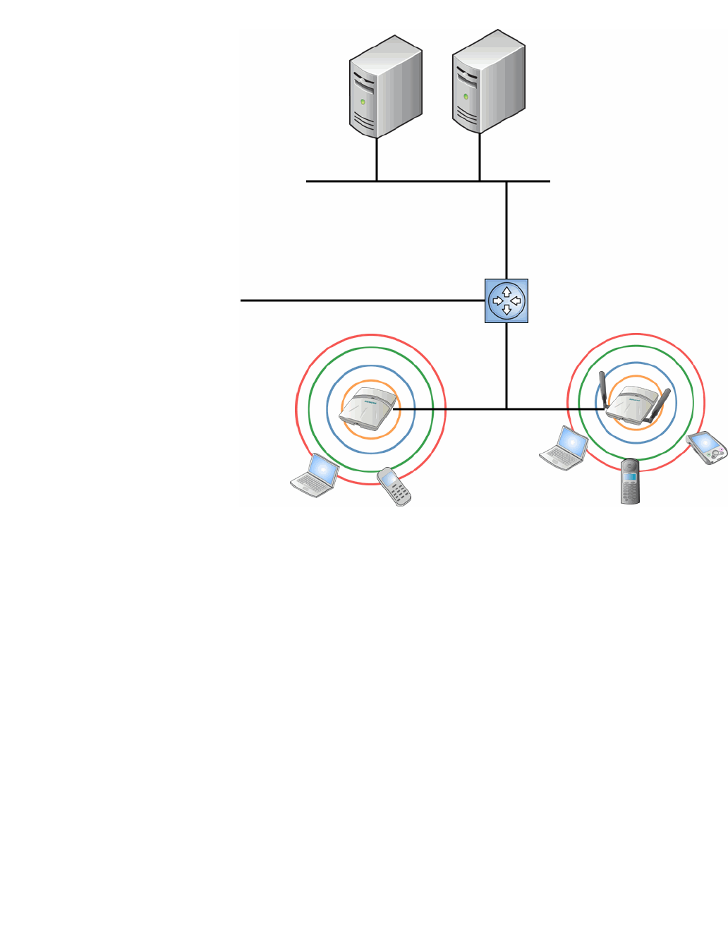
2.1 Conventional wireless LANs
Wireless communication between multiple computers requires that each
computer is equipped with a receiver/transmitter—a WLAN Network Interface
Card (NIC)—capable of exchanging digital information over a common radio
frequency. This is called an ad hoc network configuration. An ad hoc network
configuration allows wireless devices to communicate together. This setup is
defined as an independent basic service set (IBSS).
An alternative to the ad hoc configuration is the use of an access point. This may
be a dedicated hardware bridge or a computer running special software.
Computers and other wireless devices communicate with each other through this
access point. The 802.11 standard defines access point communications as
devices that allow wireless devices to communicate with a distribution system.
This setup is defined as a basic service set (BSS) or infrastructure network.
To allow the wireless devices to communicate with computers on a wired
network, the access points must be connected to the wired network providing
access to the networked computers. This topology is called bridging. With
bridging, security and management scalability is often a concern.
hwc_intro.fm
Overview of the HiPath Wireless Controller, Access Points and Convergence Software solution
Conventional wireless LANs
9034530-02, March 2010
HiPath Wireless Controller, Access Points and Convergence Software V7.11, User Guide 19
Figure 1 Standard wireless network solution example
The wireless devices and the wired networks communicate with each other using
standard networking protocols and addressing schemes. Most commonly,
Internet Protocol (IP) addressing is used.
DCHP Server
RADIUS
Authentication
Server
Ethernet Router/Switch
Wireless AP
Wireless AP
Ethernet
Wireless
Devices
Wireless
Devices

Overview of the HiPath Wireless Controller, Access Points and Convergence Software solution
hwc_intro.fm
Elements of the HiPath Wireless Controller, Access Points and Convergence Software solution
9034530-02, March 2010
20 HiPath Wireless Controller, Access Points and Convergence Software V7.11, User Guide
2.2 Elements of the HiPath Wireless Controller, Access Points and
Convergence Software solution
The HiPath Wireless Controller, Access Points and Convergence Software
solution consists of two devices:
•HiPath Wireless Controller
•Wireless APs
This architecture allows a single HiPath Wireless Controller to control many
Wireless APs, making the administration and management of large networks
much easier.
There can be several HiPath Wireless Controllers in the network, each with a set
of registered Wireless APs. The HiPath Wireless Controllers can also act as
backups to each other, providing stable network availability.
In addition to the HiPath Wireless Controllers and Wireless APs, the solution
requires three other components, all of which are standard for enterprise and
service provider networks:
•RADIUS Server (Remote Access Dial-In User Service) or other
authentication server
•DHCP Server (Dynamic Host Configuration Protocol). If you do not have a
DHCP Server on your network, you can enable the local DHCP Server on the
HiPath Wireless Controller. The local DHCP Server is useful as a general
purpose DHCP Server for small subnets. For more information, see Step 10
of Section 3.4.3, “Setting up the data ports”, on page 54.
•SLP (Service Location Protocol)
hwc_intro.fm
Overview of the HiPath Wireless Controller, Access Points and Convergence Software solution
Elements of the HiPath Wireless Controller, Access Points and Convergence Software solution
9034530-02, March 2010
HiPath Wireless Controller, Access Points and Convergence Software V7.11, User Guide 21
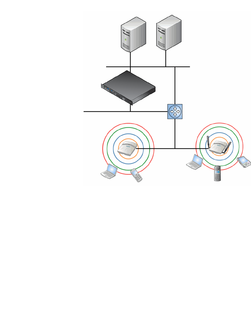
Figure 2 Siemens HiPath Wireless Controller solution
As illustrated in Figure 2, the HiPath Wireless Controller appears to the existing
network as if it were an access point, but in fact one HiPath Wireless Controller
controls many Wireless APs. The HiPath Wireless Controller has built-in
capabilities to recognize and manage the Wireless APs. The HiPath Wireless
Controller:
•Activates the Wireless APs
•Enables Wireless APs to receive wireless traffic from wireless devices
•Processes the data traffic from the Wireless APs
•Forwards or routes the processed data traffic out to the network
•Authenticates requests and applies access policies
Simplifying the Wireless APs makes them cost-effective, easy to manage, and
easy to deploy. Putting control on an intelligent centralized HiPath Wireless
Controller enables:
DCHP Server
RADIUS
Authentication
Server
Ethernet Router/Switch
Wireless AP
Wireless AP
Ethernet
Wireless
Devices
Wireless
Devices
HiPath Wireless
Controller

Overview of the HiPath Wireless Controller, Access Points and Convergence Software solution
hwc_intro.fm
Elements of the HiPath Wireless Controller, Access Points and Convergence Software solution
9034530-02, March 2010
22 HiPath Wireless Controller, Access Points and Convergence Software V7.11, User Guide
•Centralized configuration, management, reporting, and maintenance
•High security
•Flexibility to suit enterprise
•Scalable and resilient deployments with a few HiPath Wireless Controllers
controlling hundreds of Wireless APs
The HiPath Wireless Controller, Access Points and Convergence Software
system:
• Scales up to Enterprise capacity – HiPath Wireless Controllers are
scalable:
•C5110 – Up to 525 APs
•C4110 – Up to 250 APs
•C2400 – Up to 200 APs
•C20 – Up to 32 APs
•C20N – Up to 32 APs
•CRBT8210 – Up to 72 APs
•CRBT8110 – Up to 24 APs
In turn, each Wireless AP can handle up to 254 wireless devices, with each
radio supporting a maximum of 127. With additional HiPath Wireless
Controllers, the number of wireless devices the solution can support can
reach into the thousands.
• Integrates with existing network – A HiPath Wireless Controller can be
added to an existing enterprise network as a new network device, greatly
enhancing its capability without interfering with existing functionality.
Integration of the HiPath Wireless Controllers and Wireless APs does not
require any re-configuration of the existing infrastructure (for example,
VLANs).
• Integrates with the Enterasys NetSight Suite of products. For more
information, see Section 2.2.1, “Enterasys NetSight Suite integration”, on
page 23.
Plugin applications include:
•Automated Security Manager
•Inventory Manager
•NAC Manager
•Policy Control Console
•Policy Manager

hwc_intro.fm
Overview of the HiPath Wireless Controller, Access Points and Convergence Software solution
Elements of the HiPath Wireless Controller, Access Points and Convergence Software solution
9034530-02, March 2010
HiPath Wireless Controller, Access Points and Convergence Software V7.11, User Guide 23
• Offers centralized management and control – An administrator accesses
the HiPath Wireless Controller in its centralized location to monitor and
administer the entire wireless network. From the HiPath Wireless Controller
the administrator can recognize, configure, and manage the Wireless APs
and distribute new software releases.
• Provides easy deployment of Wireless APs – The initial configuration of
the Wireless APs on the centralized HiPath Wireless Controller can be done
with an automatic “discovery” technique. For more information, see Section
4.2, “Discovery and registration overview”, on page 97.
• Provides security via user authentication – Uses existing authentication
(AAA) servers to authenticate and authorize users.
• Provides security via filters and privileges – Uses virtual networking
techniques to create separate virtual networks with defined authentication
and billing services, access policies, and privileges.
• Supports seamless mobility and roaming – Supports seamless roaming of
a wireless device from one Wireless AP to another on the same HiPath
Wireless Controller or on a different HiPath Wireless Controller.
• Integrates third-party access points – Uses a combination of network
routing and authentication techniques.
• Prevents rogue devices – Unauthorized access points are detected and
identified as harmless or dangerous rogue APs.
• Provides accounting services – Logs wireless user sessions, user group
activity, and other activity reporting, enabling the generation of consolidated
billing records.
• Offers troubleshooting capability – Logs system and session activity and
provides reports to aid in troubleshooting analysis.
• Offers dynamic RF management – Automatically selects channels and
adjusts Radio Frequency (RF) signal propagation and power levels without
user intervention.
2.2.1 Enterasys NetSight Suite integration
The HiPath Wireless Controller, Access Points and Convergence Software
solution now integrates with the Enterasys NetSight Suite of products. The
Enterasys NetSight Suite of products provides a collection of tools to help you
manage networks. Its client/server architecture lets you manage your network
from a single workstation or, for networks of greater complexity, from one or more
client workstations. It is designed to facilitate specific network management tasks
while sharing data and providing common controls and a consistent user
interface. For more information, see http://www.enterasys.com/products/visibility-
control/index.aspx

Overview of the HiPath Wireless Controller, Access Points and Convergence Software solution
hwc_intro.fm
Elements of the HiPath Wireless Controller, Access Points and Convergence Software solution
9034530-02, March 2010
24 HiPath Wireless Controller, Access Points and Convergence Software V7.11, User Guide
The NetSight Suite is a family of products comprised of NetSight Console and a
suite of plugin applications, including:
• Automated Security Manager – Automated Security Manager is a unique
threat response solution that translates security intelligence into security
enforcement. It provides sophisticated identification and management of
threats and vulnerabilities. For information on how the HiPath Wireless
Controller, Access Points and Convergence Software solution integrates with
the Automated Security Manager application, see the HiPath Wireless
Controller, Access Points and Convergence Software Maintenance Guide.
• Inventory Manager – Inventory Manager is a tool for efficiently documenting
and updating the details of the ever-changing network. For information on
how the HiPath Wireless Controller, Access Points and Convergence
Software solution integrates with the Automated Security Manager
application, see the HiPath Wireless Controller, Access Points and
Convergence Software Maintenance Guide.
• NAC Manager – NAC Manager is a leading-edge NAC solution to ensure
only the right users have access to the right information from the right place
at the right time. The Enterasys NAC solution performs multi-user, multi-
method authentication, vulnerability assessment and assisted remediation.
For information on how the HiPath Wireless Controller, Access Points and
Convergence Software solution integrates with the Enterasys NAC solution,
see Section 5.3, “NAC integration with HiPath WLAN”, on page 230.
• Policy Manager
Policy Manager recognizes the HiPath Wireless Controller suite as policy
capable devices that accept partial configuration from Policy Manager.
Currently this integration is partial in the sense that NetSight is unable to
create WLAN services directly; The WLAN services need to be directly
provisioned on the controller and are represented to Policy Manager as
logical ports. The HiPath Wireless Controller allows Policy Manager to:
•Attach Topologies (assign VLAN to port) to the HiPath Wireless Controller
physical ports (Console).
•Attach policy to the logical ports (WLAN Service/SSID),
•Assign a Default Role/Policy to a WLAN Service, thus creating the VNS.
•Perform authentication operations which can then reference defined
policies for station-specific policy enforcement.
This can be seen as a three step process:
1. Deploy the controller and perform local configuration
– The HiPath Wireless Controller ships with a default SSID, attached by
default to all AP radios, when enabled.

hwc_intro.fm
Overview of the HiPath Wireless Controller, Access Points and Convergence Software solution
HiPath Wireless Controller, Access Points and Convergence Software and your network
9034530-02, March 2010
HiPath Wireless Controller, Access Points and Convergence Software V7.11, User Guide 25
– Use the basic installation wizard to complete the HiPath Wireless
Controller configuration.
2. Use Policy Manager to:
– Push the VLAN list to the HiPath Wireless Controller (Topologies)
– Attach VLANs to HiPath Wireless Controller physical ports (Console
- Complete Topology definition)
– Push RADIUS server configuration to the HiPath Wireless Controller
– Push policy definitions to the HiPath Wireless Controller
– Attach the default policy to create a VNS
3. Fine tune controller settings. For example, configuring filtering at APs and
HiPath Wireless Controller for a bridged at controller or routed topologies
and associated VNSes.
Note: Complete information about integration with Policy Manager is outside
the scope of this document.
2.3 HiPath Wireless Controller, Access Points and Convergence Software
and your network
This section is a summary of the components of the HiPath Wireless Controller,
Access Points and Convergence Software solution on your enterprise network.
The following are described in detail in this guide, unless otherwise stated:
• HiPath Wireless Controller – A rack-mountable network device that
provides centralized control over all access points and manages the network
assignment of wireless device clients associating through access points.
• Wireless AP – A wireless LAN fit access point that communicates with a
HiPath Wireless Controller. A Wireless AP can also be configured as a
sensor, which monitors and interdicts intrusions by rogue APs and rogue
clients.
• HiPath Wireless Manager – An optional component of the solution, the
HiPath Wireless Manager monitors the performance and health of the
wireless network. The HiPath Wireless Manager is particularly valuable for
installations that incorporate more than one HiPath Wireless Controller. For
more information, see the HiPath Wireless Manager User Guide.
• RADIUS Server (Remote Access Dial-In User Service) (RFC2865), or other
authentication server – An authentication server that assigns and manages
ID and Password protection throughout the network. Used for authentication
of the wireless users in either 802.1x or Captive Portal security modes. The

Overview of the HiPath Wireless Controller, Access Points and Convergence Software solution
hwc_intro.fm
HiPath Wireless Controller, Access Points and Convergence Software and your network
9034530-02, March 2010
26 HiPath Wireless Controller, Access Points and Convergence Software V7.11, User Guide
RADIUS Server system can be set up for certain standard attributes, such as
filter ID, and for the Vendor Specific Attributes (VSAs). In addition, Radius
Disconnect (RFC3576) which permits dynamic adjustment of user policy
(user disconnect) is supported.
• DHCP Server (Dynamic Host Configuration Protocol) (RFC2131) – A server
that assigns IP addresses, gateways, and subnet masks dynamically. IP
address assignment for clients can be done by the DHCP server internal to
the HiPath Wireless Controller, or by existing servers using DHCP relay. It is
also used by the Wireless APs to discover the location of the HiPath Wireless
Controller during the initial registration process. For SLP, DHCP should have
Option 78 enabled. Option 78 specifies the location of one or more SLP
Directory Agents.
• Service Location Protocol (SLP) (SLP RFC2608) – Client applications are
User Agents and services that are advertised by a Service Agent. In larger
installations, a Directory Agent collects information from Service Agents and
creates a central repository. The Siemens solution relies on registering
“siemens” as an SLP Service Agent.
• Domain Name Server (DNS) – A server used as an alternate mechanism (if
present on the enterprise network) for the automatic discovery process.
HiPath Wireless Controller, Access Points and Convergence Software relies
on the DNS for Layer 3 deployments and for static configuration of Wireless
APs. The controller can be registered in DNS, to provide DNS assisted AP
discovery. In addition, DNS can also be used for resolving RADIUS server
hostnames.
• Web Authentication Server – A server that can be used for external Captive
Portal and external authentication. The HiPath Wireless Controller has an
internal Captive portal presentation page, which allows Web authentication
(Web redirection) to take place without the need for an external Captive Portal
server.
• RADIUS Accounting Server (Remote Access Dial-In User Service)
(RFC2866) – A server that is required if RADIUS Accounting is enabled.
• Simple Network Management Protocol (SNMP) – A Manager Server that
is required if forwarding SNMP messages is enabled.
• Network infrastructure – The Ethernet switches and routers must be
configured to allow routing between the various services noted above.
Routing must also be enabled between multiple HiPath Wireless Controllers
for the following features to operate successfully:
•Availability
•Mobility
•Mitigator for detection of rogue access points
Some features also require the definition of static routes.

hwc_intro.fm
Overview of the HiPath Wireless Controller, Access Points and Convergence Software solution
HiPath Wireless Controller, Access Points and Convergence Software and your network
9034530-02, March 2010
HiPath Wireless Controller, Access Points and Convergence Software V7.11, User Guide 27
• Web Browser – A browser provides access to the HiPath Wireless Controller
Management user interface to configure the Controller, Access Points and
Convergence Software.
• SSH Enabled Device – A device that supports Secure Shell (SSH) is used
for remote (IP) shell access to the system.
• Zone Integrity – The Zone integrity server enhances network security by
ensuring clients accessing your network are compliant with your security
policies before gaining access. Zone Integrity Release 5 is supported.
• HiPath HiGuard – Provides continuous active intrusion detection and
prevention capabilities. For more information, see the HiPath HiGuard
documentation.
2.3.1 Network traffic flow
Figure 3 illustrates a simple configuration with a single HiPath Wireless Controller
and two Wireless APs, each supporting a wireless device. A RADIUS server on
the network provides authentication, and a DHCP server is used by the Wireless
APs to discover the location of the HiPath Wireless Controller during the initial
registration process. Network inter-connectivity is provided by the infrastructure
routing and switching devices.
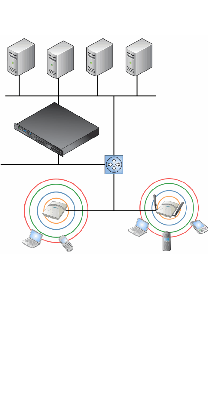
Overview of the HiPath Wireless Controller, Access Points and Convergence Software solution
hwc_intro.fm
HiPath Wireless Controller, Access Points and Convergence Software and your network
9034530-02, March 2010
28 HiPath Wireless Controller, Access Points and Convergence Software V7.11, User Guide
Figure 3 Traffic Flow diagram
Each wireless device sends IP packets in the 802.11 standard to the Wireless AP.
The Wireless AP uses a UDP (User Datagram Protocol) based tunnelling
protocol. In tunneled mode of operation, it encapsulates the packets and forwards
them to the HiPath Wireless Controller. The HiPath Wireless Controller
decapsulates the packets and routes these to destinations on the network. In a
typical configuration, access points can be configured to locally bridge traffic (to
a configured VLAN) directly at their network point of attachment.
The HiPath Wireless Controller functions like a standard L3 router or L2 switch.
It is configured to route the network traffic associated with wireless connected
users. The HiPath Wireless Controller can also be configured to simply forward
traffic to a default or static route if dynamic routing is not preferred or available.
Packet transmission
Control and Routing
>HWC authenticates wireless user
>HWC forwards IP packet to wired
network
Tunnelling
>AP sends data traffic to HWC
through UDP tunnel called WASSP
>HWC controls Wireless AP
through WASSP tunnel
>Using WASSP tunnels, HWC
allows wireless clients to roam to
Wireless APs on different HWCs
802.11 packet transmission
802.11 beacon and probe, wireless
device associates
with a Wireless AP
by its SSID Wireless Devices
Router/Switch
HiPath Wireless
Controller
RADIUS
Authentication
Server
External
CP Server
External Web
Authentication
Server
Wireless APs
DHCP
Server

hwc_intro.fm
Overview of the HiPath Wireless Controller, Access Points and Convergence Software solution
HiPath Wireless Controller, Access Points and Convergence Software and your network
9034530-02, March 2010
HiPath Wireless Controller, Access Points and Convergence Software V7.11, User Guide 29
2.3.2 Network security
The HiPath Wireless Controller, Access Points and Convergence Software
system provides features and functionality to control network access. These are
based on standard wireless network security practices.
Current wireless network security methods provide protection. These methods
include:
•Shared Key authentication that relies on Wired Equivalent Privacy (WEP)
keys
•Open System that relies on Service Set Identifiers (SSIDs)
•802.1x that is compliant with Wi-Fi Protected Access (WPA)
•Captive Portal based on Secure Sockets Layer (SSL) protocol
The HiPath Wireless Controller, Access Points and Convergence Software
system provides the centralized mechanism by which the corresponding security
parameters are configured for a group of users.
•Wired Equivalent Privacy (WEP) is a security protocol for wireless local area
networks defined in the 802.11b standard
•Wi-Fi Protected Access version 1 (WPA1™) with Temporal Key Integrity
Protocol (TKIP)
•Wi-Fi Protected Access version 2 (WPA2™) with Advanced Encryption
Standard (AES) and Counter Mode with Cipher Block Chaining Message
Authentication Code (CCMP)
HiPath HiGuard
The HiPath HiGuard solution provides network security, including:
• Monitoring – 2.4 GHz and 5 GHz, all channels association activity
• Identifying – Detect all Wi-Fi activity and correlate information from multiple
sensors
• Auto-Classifying – Limit user intervention to maximize the protection of all
devices from all threats
•Preventing – Automatically block threats through dedicated sensors to
prevent any impact on the service level
• Visualizing – Visualize measured coverage for service, detection, and
prevention
• Locating – Identify the position of rogue APs and clients on the floor-plan for
permanent removal

Overview of the HiPath Wireless Controller, Access Points and Convergence Software solution
hwc_intro.fm
HiPath Wireless Controller, Access Points and Convergence Software and your network
9034530-02, March 2010
30 HiPath Wireless Controller, Access Points and Convergence Software V7.11, User Guide
2.3.2.1 Authentication
The HiPath Wireless Controller relies on a RADIUS server, or authentication
server, on the enterprise network to provide the authentication information
(whether the user is to be allowed or denied access to the network). A RADIUS
client is implemented to interact with infrastructure RADIUS servers.
The HiPath Wireless Controller provides authentication using:
•Captive Portal – a browser-based mechanism that forces users to a Web
page
•RADIUS (using IEEE 802.1x)
The 802.1x mechanism is a standard for authentication developed within the
802.11 standard. This mechanism is implemented at the wireless Port, blocking
all data traffic between the wireless device and the network until authentication is
complete. Authentication by 802.1x standard uses Extensible Authentication
Protocol (EAP) for the message exchange between the HiPath Wireless
Controller and the RADIUS server.
When 802.1x is used for authentication, the HiPath Wireless Controller provides
the capability to dynamically assign per-wireless-device WEP keys (called per
session WEP keys in 802.11). In the case of WPA, the HiPath Wireless Controller
is not involved in key assignment. Instead, the controller is involved in the
information exchange between RADIUS server and the user’s wireless device to
negotiate the appropriate set of keys. With WPA2 the material exchange
produces a Pairwise Master Key which is used by the AP and the user to derive
their temporal keys. (The keys change over time.)
In the HiPath Wireless Controller, Access Points and Convergence Software
solution, a RADIUS redundancy feature is provided, where you can define a
failover RADIUS server (up to 2 servers) in the event that the active RADIUS
server becomes unresponsive.
2.3.2.2 Privacy
Privacy is a mechanism that protects data over wireless and wired networks,
usually by encryption techniques.
HiPath Wireless Controller, Access Points and Convergence Software supports
the Wired Equivalent Privacy (WEP) standard common to conventional access
points.
It also provides Wi-Fi Protected Access version 1 (WPA v.1) encryption, based on
Pairwise Master Key (PMK) and Temporal Key Integrity Protocol (TKIP). The
most secure encryption mechanism is WPA version 2, using Advanced
Encryption Standard (AES).
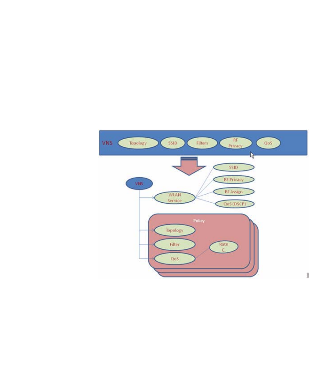
hwc_intro.fm
Overview of the HiPath Wireless Controller, Access Points and Convergence Software solution
HiPath Wireless Controller, Access Points and Convergence Software and your network
9034530-02, March 2010
HiPath Wireless Controller, Access Points and Convergence Software V7.11, User Guide 31
2.3.3 Virtual Network Services
Virtual Network Services (VNS) provide a versatile method of mapping wireless
networks to the topology of an existing wired network.
In releases prior to V7.0, a VNS was a collection of operational entities. Starting
with Release V7.0, a VNS becomes the binding of reusable components :
•WLAN Service components that define the radio attributes, privacy and
authentication settings, and QoS attributes of the VNS
•Policy components that define the topology (typically a VLAN), filter rules,
and Class of Service applied to the traffic of a station.
Figure 4 illustrates the transition of the concept of a VNS to a binding of reusable
components.
Figure 4 VNS as a binding of reusable components
WLAN Service components and Policy components can be configured separately
and associated with a VNS when the VNS is created or modified. ALternatively,
they can be configured during the process of creating a VNS.
Additionally, Policies can be created using the Enterasys NetSight Policy
Manager and pushed to the HiPath Wireless Controller. Policy assignment
ensures that the correct topology and traffic behavior are applied to a user
regardless of WLAN service used or VNS assignment.
When VNS components are set up on the HiPath Wireless Controller, among
other things, a range of IP addresses is set aside for the HiPath Wireless
Controller’s DHCP server to assign to wireless devices.

Overview of the HiPath Wireless Controller, Access Points and Convergence Software solution
hwc_intro.fm
HiPath Wireless Controller, Access Points and Convergence Software and your network
9034530-02, March 2010
32 HiPath Wireless Controller, Access Points and Convergence Software V7.11, User Guide
If the OSPF routing protocol is enabled, the HiPath Wireless Controller advertises
the routed topologies as reachable segments to the wired network infrastructure.
The controller routes traffic between the wireless devices and the wired network.
The HiPath Wireless Controller also supports VLAN-bridged assignment for
VNSs. This allows the controller to directly bridge the set of wireless devices
associated with a WLAN service directly to a specified core VLAN.
Each HiPath Wireless Controller model can support a specified number of active
VNSs, as listed below:
•C5110 – Up to 128 VNSs
•C4110 – Up to 64 VNSs
•C2400 – Up to 64 VNSs
•C20 – Up to 8 VNSs
•C20N – Up to 8 VNSs
•CRBT8210 – Up to 16 VNSs
•CRBT8110 – Up to 8 VNSs
The Wireless AP radios can be assigned to each of the configured WLAN
services and, therefore, VNSs in a system. Each Wireless AP can be the subject
of 16 service assignments — 8 assignments per radio — which corresponds to
the number of SSIDs it can support. Once a radio has all 8 slots assigned, it is no
longer eligible for further assignment.
2.3.4 VNS components
The distinct constituent high-level configurable umbrella elements of a VNS are:
•Topology
•Policy
•WLAN Services
2.3.4.1 Topology
Topologies represent the networks with which the HiPath Wireless Controller and
its APs interacts. The main configurable attributes of a topology are:
•Name - a string of alphanumeric characters designated by the administrator.
•VLAN ID - the VLAN identifier as specified in in the IEEE 802.1Q definition.
•VLAN tagging options.

hwc_intro.fm
Overview of the HiPath Wireless Controller, Access Points and Convergence Software solution
HiPath Wireless Controller, Access Points and Convergence Software and your network
9034530-02, March 2010
HiPath Wireless Controller, Access Points and Convergence Software V7.11, User Guide 33
•Port of presence for the topology on the HiPath Wireless Controller. (This
attribute is not required for Routed and Bridged at AP topologies.)
•Interface. This attribute is the IP (L3) address assigned to the HiPath Wireless
Controller on the network described by the topology. (Optional.)
•Type. This attribute describes how traffic is forwarded on the topology.
Options are:
– “Physical” - the topology is the native topology of a data plane and it
represents the acrual Ethernet ports
– "Management" - the native topology of the HiPath Wireless Controller
management port
– "Routed" - the controller is the routing gateway for the routed topology.
– "Bridged at Controller" - the user traffic is bridged (in the L2 sense)
between wireless clients and the core network infrastructure.
– "Bridged at AP" - the user traffic is bridged locally at the AP without being
redirected to the HiPath Wireless Controller.
•Exception Filters. Specifies which traffic has access to the HiPath Wireless
Controller from the wireless clients or the infrastructure network.
•Certificates.<<SEE DISCUSSION ABOUT AUTHENTICATION?? See Sandy
Pavel’s review notes>>
•Multicast filters. Defines the multicast groups that are allowed on a specific
topology segment.
2.3.4.2 Policy
A Policy is a collection of attributes and rules that determine actions taken user
traffic accesses the wired network through the WLAN service (associated to the
WLAN Service's SSID). Depending upon its type, a VNS can have between 1 and
3 Authorization Policies associated with it:
1. Default non-authorized policy — This is a mandatory policy that covers all
traffic from stations that have not authenticated. At the administrator's
discretion the default non-authorized policy can be applied to the traffic of
authenticated stations as well.
2. Default authorized policy — This is a mandatory policy that applies to the
traffic of authenticated stations for which no other policy was explicitly
specified. It can be the same as the default non-authorized policy.
3. Third party AP policy — This policy applies to the list of MAC addresses
corresponding to the wired interfaces of third party APs specifically defined
by the administrator to be providing the RF access as an AP WLAN Service.
This policy is only relevant when applied to third party AP WLAN Services.

Overview of the HiPath Wireless Controller, Access Points and Convergence Software solution
hwc_intro.fm
HiPath Wireless Controller, Access Points and Convergence Software and your network
9034530-02, March 2010
34 HiPath Wireless Controller, Access Points and Convergence Software V7.11, User Guide
As mentioned previously, policies can be configured using the NetSight Policy
Manager and pushed to the HiPath Wireless Controller, or they can be configured
directly on the controller. When using Policy Manager, you should note that the
HiPath Wireless Controller implements most of the Policy Manager concept of
Policy except for QoS assignment. The HiPath Wireless Controller implements
per policy inbound and outbound rate limits, but not policy-based DSCP
remarking or queue assignment.
2.3.4.3 WLAN Services
A WLAN Service represents all the RF, authentication and QoS attributes of a
wireless access service offered by the HiPath Wireless Controller and its APs. A
WLAN Service can be one of three basic types:
•Standard — A conventional service. Only APs running HiPath Wireless
software can be part of this WLAN Service. This type of service is useable as
a Bridged at Controller, Bridged at AP, or Routed Topology. This type of
service provides access for mobile stations. Policies can be associated with
this type of WLAN service to create a VNS.
•Third Party AP — A Wireless Service offered by third party APs. This type of
service provides access for mobile stations. Policies can be assigned to this
type of WLAN service to create a VNS.
•WDS — This represent a group of APs organized into a hierarchy for
purposes of providing a Wireless Distribution Service. This type of service is
in essence a wireless trunking service rather than a service that provides
access for stations. As such, this type of service cannot have policies
attached to it.
In release V7.0, the components of a WLAN Service map to the corresponding
components of a VNS in previous releases. The exception is that WLAN Services
are not classified as SSID-based or AAA-based, as was the case in previous
releases. Instead, the administrator makes an explicit choice of the type of
authentication to use on the WLAN Service. If his choice of authentication option
conflicts with any of his other authentication or privacy choices, the WLAN
Service cannot be enabled.
2.3.5 Static routing and routing protocols
Routing can be used on the HiPath Wireless Controller to support the VNS
definitions. Through the user interface you can configure routing on the HiPath
Wireless Controller to use one of the following routing techniques:
• Static routes – Use static routes to set the default route of a HiPath Wireless
Controller so that legitimate wireless device traffic can be forwarded to the
default gateway.

hwc_intro.fm
Overview of the HiPath Wireless Controller, Access Points and Convergence Software solution
HiPath Wireless Controller, Access Points and Convergence Software and your network
9034530-02, March 2010
HiPath Wireless Controller, Access Points and Convergence Software V7.11, User Guide 35
• Open Shortest Path First (OSPF, version 2) (RFC2328) – Use OSPF to
allow the HiPath Wireless Controller to participate in dynamic route selection.
OSPF is a protocol designed for medium and large IP networks with the ability
to segment routes into different areas by routing information summarization
and propagation. Static Route definition and OSPF dynamic learning can be
combined, and the precedence of a static route definition over dynamic rules
can be configured by selecting or clearing the Override dynamic routes
option checkbox.
• Next-hop routing – Use next-hop routing to specify a unique gateway to
which traffic on a VNS is forwarded. Defining a next-hop for a VNS forces all
the traffic in the VNS to be forwarded to the indicated network device,
bypassing any routing definitions of the controller's route table.
2.3.6 Mobility and roaming
In typical simple configurations, APs are setup as bridges that bridge wireless
traffic to the local subnet. In bridging configurations, the user obtains an IP
address from the same subnet as the AP, assuming no VLAN trunking functinality.
If the user roams between APs on the same subnet, it is able to keep using the
same IP address. However, if the user roams to another AP outside of that
subnet, its IP address is no longer valid. The user's client device must recognize
that the IP address it has is no longer valid and re-negotiate a new one on the
new subnet. This mechanism does not mandate any action on the user. The
recovery procedure is entirely client device dependent. Some clients
automatically attempt to obtain a new address on roam (which affects roaming
latency), while others will hold on to their IP address. This loss of IP address
continuity seriously affects the client's experience in the network, because in
some cases it can take minutes for a new address to be negotiated.
The HiPath Wireless Controller, Access Points and Convergence Software
solution centralizes the user's network point of presence, therefore abstracting
and decoupling the user's IP address assignment from that of the APs location
subnet. That means that the user is able to roam across any AP without loosing
its own IP address, regardless of the subnet on which the serving APs are
deployed.
In addition, a HiPath Wireless Controller can learn about other HiPath Wireless
Controllers on the network and then exchange client session information. This
enables a wireless device user to roam seamlessly between different Wireless
APs on different HiPath Wireless Controllers.

Overview of the HiPath Wireless Controller, Access Points and Convergence Software solution
hwc_intro.fm
HiPath Wireless Controller, Access Points and Convergence Software and your network
9034530-02, March 2010
36 HiPath Wireless Controller, Access Points and Convergence Software V7.11, User Guide
2.3.7 Network availability
The HiPath Wireless Controller, Access Points and Convergence Software
solution provides availability against Wireless AP outages, HiPath Wireless
Controller outages, and even network outages. The HiPath Wireless Controller in
a VLAN bridged topology can potentially allow the user to retain the IP address
in a failover scenario, if the VNS/VLAN is common to both controllers. For
example, availability is provided by defining a paired controller configuration by
which each peer can act as the backup controller for the other's APs. APs in one
controller are allowed to failover and register with the alternate controller.
If a HiPath Wireless Controller fails, all of its associated Wireless APs can
automatically switch over to another HiPath Wireless Controller that has been
defined as the secondary or backup HiPath Wireless Controller. If the AP reboots,
the original HiPath Wireless Controller is restored. The original HiPath Wireless
Controller is restored if it is active. However, active APs will continue to be
attached to the failover controller until the administrator releases them back to the
original home controller.
2.3.8 Quality of Service (QoS)
HiPath Wireless Controller, Access Points and Convergence Software solution
provides advanced Quality of Service (QoS) management to provide better
network traffic flow. Such techniques include:
• WMM (Wi-Fi Multimedia) – WMM is enabled per WLAN service. The HiPath
Wireless Controller provides centralized management of the AP features. For
devices with WMM enabled, the standard provides multimedia
enhancements for audio, video, and voice applications. WMM shortens the
time between transmitting packets for higher priority traffic. WMM is part of
the 802.11e standard for QoS. In the context of the HiPath Wireless Solution,
the ToS/DSCP field is used for classification and proper class of service
mapping, output queue seselectin, and priority tagging.
• IP ToS (Type of Service) or DSCP (Diffserv Codepoint) – The ToS/DSCP
field in the IP header of a frame indicates the priority and class of service for
each frame. The IP TOS and/or DSCP is maintained and transported within
CTP (CAPWAP Tunneling Protocol) by copying the user IP QoS information
to the CTP header—this is referred to as Adaptive QoS.
• Rate Control – Rate Control for user traffic can also be considered as an
aspect of QoS. As part of Policy definition, the user can specify (default)
policy that includes Ingress and Egress rate control. Ingress rate control
applies to traffic generated by wireless clients and Egress rate control applies
to traffic targeting specific wireless clients. The bit-rates can be configured as
part of globally available profiles which can be used by any particular
configuration. A global default is also defined.

hwc_intro.fm
Overview of the HiPath Wireless Controller, Access Points and Convergence Software solution
HiPath Wireless Controller product family
9034530-02, March 2010
HiPath Wireless Controller, Access Points and Convergence Software V7.11, User Guide 37
Quality of Service (QoS) management is also provided by:
•Assigning high priority to a WLAN service
•Adaptive QoS (automatic and all time feature)
•Support for legacy devices that use SpectraLink Voice Protocol (SVP) for
prioritizing voice traffic (configurable)
2.4 HiPath Wireless Controller product family
The HiPath Wireless Controller is available in the following product families:
HiPath Wireless Controller
Model Number Specifications
C5110 •Three data ports supporting up to 525 Wireless APs
– 2 fiber optic SR (10Gbps)
– 1 Ethernet port GigE
•One management port (Ethernet) GigE
•One console port (DB9 serial)
•Four USB ports — two on each front and back panel
(only one active at a time)
•Redundant dual power supply unit
C4110 •Four GigE ports supporting up to 250 Wireless APs
•One management port (Ethernet) GigE
•One console port (DB9 serial)
•Four USB ports (only one active at a time)
•Redundant dual power supply unit
C2400 •Four GigE ports supporting up to 200 Wireless APs
•One management port (10/100 BaseT)
•One console port (DB9 serial)
•Redundant dual power supply unit
C20 •Two GigE ports supporting up to 32 Wireless APs
•One management port GigE
•One console port (USB control)
•One USB port
•Power supply standard (R)
C20N •Two GigE ports supporting up to 32 Wireless APs
•One management port GigE
•One console port (DB9 serial)
•One USB port
CRBT8210 •One GigE ports supporting up to 72 Wireless APs
•One management port (10/100 Base)
•One console port (DB9 serial)
CRBT8110 •One GigE ports supporting up to 24 Wireless APs
•One management port (10/100 Base)
•One console port (DB9 serial)
•One USB port
Table 1 HiPath Wireless Controller product families

Overview of the HiPath Wireless Controller, Access Points and Convergence Software solution
hwc_intro.fm
HiPath Wireless Controller product family
9034530-02, March 2010
38 HiPath Wireless Controller, Access Points and Convergence Software V7.11, User Guide

hwc_startup.fm
9034530-02, March 2010
HiPath Wireless Controller, Access Points and Convergence Software V7.11, User Guide 39
Configuring the HiPath Wireless Controller
System configuration overview
3 Configuring the HiPath Wireless Controller
This chapter describes the steps involved in the initial configuration and setup, of
the HiPath Wireless Controller, including:
•System configuration overview
•Logging on to the HiPath Wireless Controller
•Working with the basic installation wizard
•Configuring the HiPath Wireless Controller for the first time
•Additional ongoing operations of the system
3.1 System configuration overview
The following section provides a high-level overview of the steps involved in the
initial configuration of your system:
Step 1 – Before you begin configuration
Research the type of WLAN deployment that is required. For example, topology
and VLAN IDs, SSIDs, security requirements, and filter policies.
Step 2 – Prepare the network servers
Ensure that the external servers, such as DHCP and RADIUS servers (if
applicable) are available and appropriately configured.
Step 3 – Install the hardware
Install the HiPath Wireless Controller. For more information, see the following:
•HiPath Wireless Controller C5110 Quick Reference.
•HiPath Wireless Controller C4110 Quick Reference.
•HiPath Wireless Controller, Access Points and Convergence Software
Controller C2400 Installation Instructions.
•HiPath Wireless Controller, Access Points and Convergence Software
Controller C20 Installation Instructions
•HiPath Wireless Controller Module for Enterasys Matrix ® N-Series,
Hardware Installation Guide
•If you are deploying the HiPath Wireless Controller C20N, use the DFE
CLI to configure the VLAN assignments for the corresponding PC ports
on the Controller Module. For example:

Configuring the HiPath Wireless Controller
hwc_startup.fm
System configuration overview
9034530-02, March 2010
40 HiPath Wireless Controller, Access Points and Convergence Software V7.11, User Guide
set port vlan pc.slot.port# vlan-id
Note: The VLAN configuration of the PC ports on the DFE module (VLAN ID
and tagged vs. untagged) must match the VLAN configuration of the
controller’s data ports defined using the HiPath Wireless Assistant.
Step 4 – Perform the first time setup
Perform the first time setup of the HiPath Wireless Controller on the physical
network, which includes configuring the IP addresses of the interfaces on the
HiPath Wireless Controller:
•Change the default IP address to be the relevant subnet point of attachment
to the existing network. The IP address is 10.0.#.1 is set by default the first
time you start up the controller.
•To manage the HiPath Wireless Controller through the interface configured
above, select the Mgmt checkbox on the Interfaces tab.
•Configure the data port interfaces to be on separate VLANs, matching the
VLANs configured in step 3 above. Ensure also that the tagged vs. untagged
state is consistent with the switch port (DFE if configuring the HiPath Wireless
Controller C20N) configuration.
•Configure the time zone. Because changing the time zone requires restarting
the HiPath Wireless Controller, it is recommended that you configure the time
zone during the initial installation and configuration of the HiPath Wireless
Controller to avoid network interruptions. For more information, see Section
3.4.10, “Configuring network time”, on page 79.
Apply the activation license key
Apply an activation key file. If an activation key is not applied, the HiPath Wireless
Controller functions with some features enabled in demonstration mode. Not all
features are enabled in demonstration mode. For example, mobility is not
enabled and cannot be used.
Caution: Whenever the licensed region changes on the HiPath Wireless
Controller, all Wireless APs are changed to Auto Channel Select to prevent
possible infractions to local RF regulatory requirements. If this occurs, all
manually configured radio channel settings will be lost.
Installing the new license key before upgrading will prevent the HiPath Wireless
Controller from changing the licensed region, and in addition, manually
configured channel settings will be maintained. For more information, see the
HiPath Wireless Controller, Access Points and Convergence Software
Maintenance Guide.

hwc_startup.fm
Configuring the HiPath Wireless Controller
System configuration overview
9034530-02, March 2010
HiPath Wireless Controller, Access Points and Convergence Software V7.11, User Guide 41
Configure for remote access
In addition, the first time setup also involves configuring the HiPath Wireless
Controller for remote access, which includes:
•Setting up an administration station (laptop) on subnet 192.168.10.0/24. By
default, the HiPath Wireless Controller's Management interface is configured
with the static IP address 192.168.10.1.
•Configuring the HiPath Wireless Controller’s management interface.
•Configuring the data interfaces.
Set up the HiPath Wireless Controller on the network by configuring the
physical data ports.
•Configure the routing table.
Configure static routes or OSPF parameters, if appropriate to the network.
For more information, see Section 3.4, “Configuring the HiPath Wireless
Controller for the first time”, on page 50.
Step 5 – Configure the Topologies
Configure the traffic topologies your network must support. Topologies represent
the Controller’s points of network attachment, therefore VLANs and port
assignments need to be coordinated with the corresponding network switch
ports. For more information, see Section 6.8, “Configuring a Topology”, on page
296.
Step 6 – Configure Policies
Policies are typically bound to Topologies. Policy application assigns user traffic
to the corresponding network point.
•Policies define user access rights (filtering or ACL)
•Polices reference user's rate control profile.
For more information, see Section 6.10, “Configuring Policy”, on page 350.
Step 7 – Configure WLAN Services
•Define SSID and privacy settings for the wireless link.
•Select the set of APs/Radios on which the service is present.
•Configure the method of credential authentication for wireless users (None,
Internal CP, External CP, GuestPortal, 802.1x[EAP])
For more information, see Section 6.9, “Configuring WLAN Services”, on page
308.

Configuring the HiPath Wireless Controller
hwc_startup.fm
System configuration overview
9034530-02, March 2010
42 HiPath Wireless Controller, Access Points and Convergence Software V7.11, User Guide
Step 8 – Create the VNSs
A VNS binds a “WLAN Service” to a “Policy” that will be used for default
assignment upon a users’ network attachment.
You can create topologies, policies, and WLAN services first, before VNS
configuration a VNS, or you can select one of the wizards (such as the VNS
wizard), or you can simply select to create new VNS.
The VNS page then allows for in-place creation and definition of any dependency
it may require, such as:
•Creating a new WLAN Service
•Creating a new Policy
•Creating a new Topology (within a Policy)
•Creating new Rate controls, etc.
The default shipping configuration does not ship any pre-configured WLAN
Services, VNSs, or Policies.
Step 9– Install, register, and assign APs to the VNS
•Confirm the latest firmware version is loaded. For more information, see
Section 4.10, “Performing Wireless AP software maintenance”, on page 217.
•Deploy Wireless APs to their corresponding network locations.
•If applicable, configure a default AP template for common radio assignment,
whereby APs automatically receive complete configuration. For typical
deployments where all APs are to have the same configuration, this feature
will expedite deployment, as an AP will automatically receive full configuration
(including VNS-related assignments) upon initial registration with the HiPath
Wireless Controller. If applicable, modify the properties or settings of the
Wireless APs. For more information, see Chapter 4, “Configuring the
Wireless AP”.
•Connect the Wireless APs to the HiPath Wireless Controller.
•Once the Wireless APs are powered on, they automatically begin the
Discovery process of the HiPath Wireless Controller, based on factors that
include:
•Their Registration mode (on the Wireless AP Registration screen)
•The enterprise network services that will support the discovery process
hwc_startup.fm
Configuring the HiPath Wireless Controller
Logging on to the HiPath Wireless Controller
9034530-02, March 2010
HiPath Wireless Controller, Access Points and Convergence Software V7.11, User Guide 43
3.2 Logging on to the HiPath Wireless Controller
1. Launch your Web browser (Internet Explorer version 6.0 or higher, or
FireFox).
2. In the browser address bar, type the following:
https://192.168.10.1:5825
This launches the HiPath Wireless Assistant. The login screen is displayed.
3. In the User Name box, type your user name.
4. In the Password box, type your password.
Note: The HiPath Wireless Controller default password is abc123.
5. Click Login. The HiPath Wireless Assistant main menu screen is displayed.
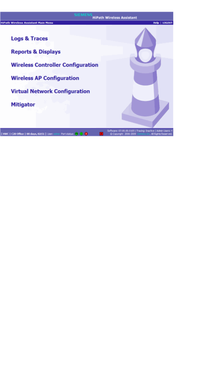
Configuring the HiPath Wireless Controller
hwc_startup.fm
Working with the basic installation wizard
9034530-02, March 2010
44 HiPath Wireless Controller, Access Points and Convergence Software V7.11, User Guide
3.3 Working with the basic installation wizard
The HiPath Wireless Controller, Access Points and Convergence Software
system provides a basic installation wizard that can help administrators configure
the minimum HiPath Wireless Controller settings that are necessary to deploy a
functioning HiPath wireless solution on a network.
Administrators can use the basic installation wizard to quickly configure the
HiPath Wireless Controller for deployment, and then once the installation is
complete, continue to revise the HiPath Wireless Controller configuration
accordingly.
The basic installation wizard is automatically launched when an administrator
logs on to the HiPath Wireless Controller for the first time, including if the system
has been reset to the factory default settings. In addition, the basic installation
wizard can also be launched at any time from the left pane of the HiPath Wireless
Controller Configuration screen.
To configure the HiPath Wireless Controller with the basic installation
wizard:
1. Log on to the HiPath Wireless Controller. For more information, see Section
3.2, “Logging on to the HiPath Wireless Controller”, on page 43.
2. From the main menu, click Wireless Controller Configuration. The HiPath
Wireless Controller Configuration screen is displayed.
3. In the left pane, click Installation Wizard. The Basic Installation Wizard
screen is displayed.
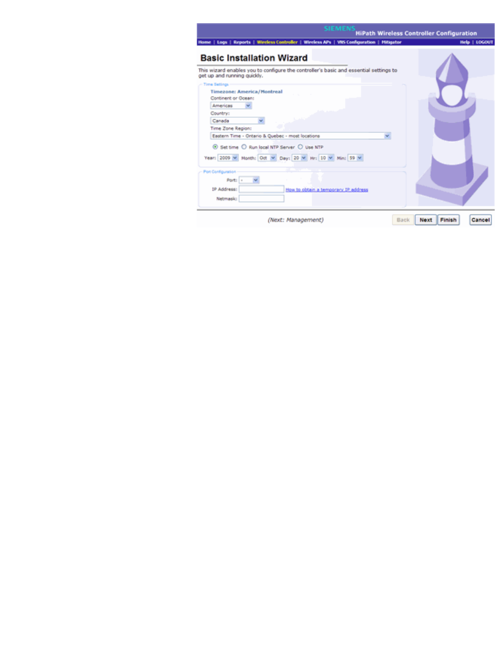
hwc_startup.fm
Configuring the HiPath Wireless Controller
Working with the basic installation wizard
9034530-02, March 2010
HiPath Wireless Controller, Access Points and Convergence Software V7.11, User Guide 45
4. In the Time Settings section, configure the HiPath Wireless Controller
timezone:
• Continent or Ocean – Click the appropriate large-scale geographic
grouping for the time zone.
• Country – Click the appropriate country for the time zone. The contents
of the drop-down list change, based on the selection in the Continent or
Ocean drop-down list.
• Time Zone Region – Click the appropriate time zone region for the
selected country.
5. To configure the HiPath Wireless Controller’s time, do one of the following:
•To manually set the HiPath Wireless Controller time, use the Year,
Month, Day, HR, and Min. drop-down lists to specify the time.
•To use the HiPath Wireless Controller as the NTP time server, select the
Run local NTP Server option.
•To use NTP to set the HiPath Wireless Controller time, select the Use
NTP option, and then type the IP address of an NTP time server that is
accessible on the enterprise network.
The Network Time Protocol is a protocol for synchronizing the clocks of
computer systems over packet-switched data networks.
6. In the Port Configuration section, click the physical interface of the HiPath
Wireless Controller you want to assign as a data port. The system assigns
default IP Address and Netmask values for the data port. If applicable, type
a different IP address and netmask for the selected physical interface.
For information on how to obtain a temporary IP address from the network,
click How to obtain a temporary IP address.
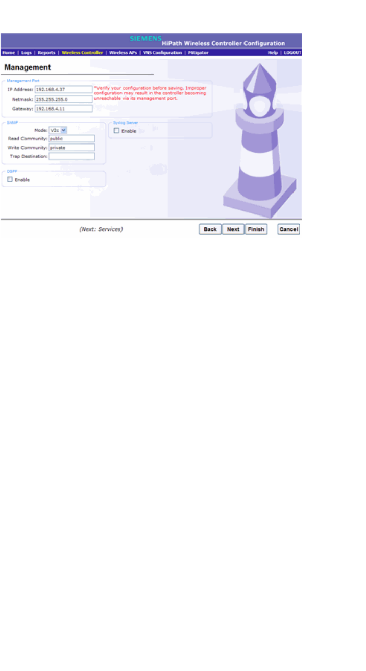
Configuring the HiPath Wireless Controller
hwc_startup.fm
Working with the basic installation wizard
9034530-02, March 2010
46 HiPath Wireless Controller, Access Points and Convergence Software V7.11, User Guide
7. Click Next. The Management screen is displayed.
8. In the Management Port section, confirm the port configuration values that
were defined when the HiPath Wireless Controller was physically deployed
on the network. If applicable, edit these values:
• IP Address – Displays the IP address for the HiPath Wireless Controller’s
management port. Revise this as appropriate for the enterprise network.
• Netmask – Displays the appropriate subnet mask for the IP address to
separate the network portion from the host portion of the address.
• Gateway – Displays the default gateway of the network.
9. In the SNMP section, click V2c or V3 in the Mode drop-down list to enable
SNMP, if applicable. Only one mode can be supported on the controller at a
time.
If you selected V2c, do the following:
• Read Community – Type the password that is used for read-only SNMP
communication.
• Write Community – Type the password that is used for write SNMP
communication.
• Trap Destination – Type the IP address of the server used as the
network manager that will receive SNMP messages.
If you selected V3, do the following:
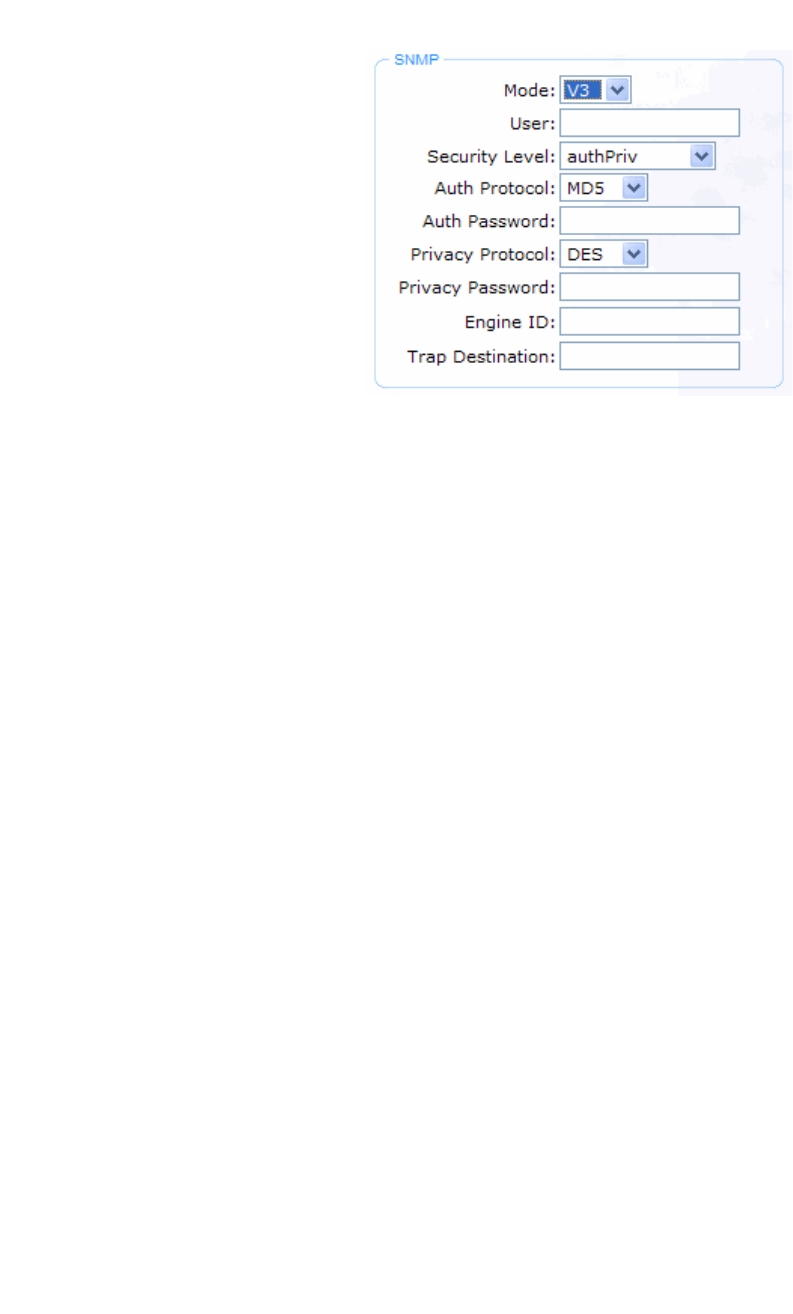
hwc_startup.fm
Configuring the HiPath Wireless Controller
Working with the basic installation wizard
9034530-02, March 2010
HiPath Wireless Controller, Access Points and Convergence Software V7.11, User Guide 47
•User – Enter the name of the user account.
• Security Level – Select the security level for this user account. Choices
are: authPriv, authNoPriv, noAuthnoPriv.
• Auth Protocol – If you have selected a security level of authPriv or
authNoPriv, select the authentication protocol. Choices are: MD5, SHA,
None.
• Auth Password – If you have selected a security level of authPriv or
authNoPriv, enter an authentication password.
• Privacy Protocol – If you have selected the security level of authPriv,
select the privacy protocol. Choices are: DES, None
• Privacy Password – If you have selected the security level of authPriv,
enter a privacy password.
•Engine ID – If desired, enter an engine ID. The ID can be between 5 and
32 bytes long, with no spaces, control characters, or tabs.
• Trap Destination – If desired, enter the IP address of a trap destination.
10. In the OSPF section, select the Enable checkbox to enable OSPF, if
applicable. Use OSPF to allow the HiPath Wireless Controller to participate
in dynamic route selection. OSPF is a protocol designed for medium and
large IP networks with the ability to segment routes into different areas by
routing information summarization and propagation.
Do the following:
•Port – Click the physical interface of the HiPath Wireless Controller you
want to assign as a router port.
•Area ID – Type the desired area. Area 0.0.0.0 is the main area in OSPF.
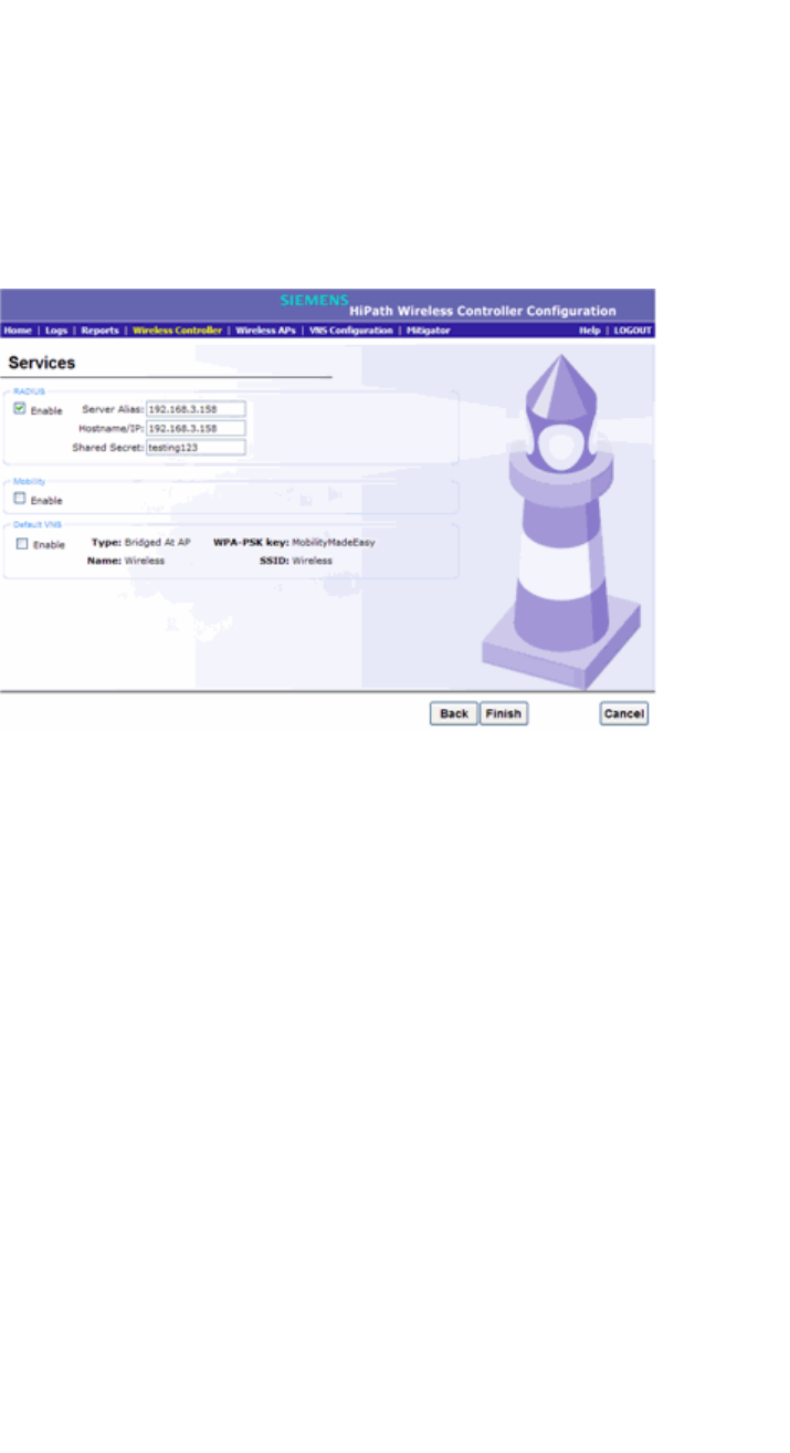
Configuring the HiPath Wireless Controller
hwc_startup.fm
Working with the basic installation wizard
9034530-02, March 2010
48 HiPath Wireless Controller, Access Points and Convergence Software V7.11, User Guide
11. In the Syslog Server section, select the Enable checkbox to enable the
syslog protocol for the HiPath Wireless Controller, if applicable. Syslog is a
protocol used for the transmission of event notification messages across
networks.
Do the following:
In the IP Address box, type the IP address of the syslog server.
12. Click Next. The Services screen is displayed.
13. In the RADIUS section, select the Enable checkbox to enable RADIUS login
authentication, if applicable. RADIUS login authentication uses a RADIUS
server to authenticate user login attempts. RADIUS is a client/server
authentication and authorization access protocol used by a network access
server (NAS) to authenticate users attempting to connect to a network device.
Do the following:
•Server Alias – Type a name that you want to assign to the RADIUS
server. You can type a name or IP address of the server.
•Hostname/IP – Type the RADIUS server’s hostname or IP address.
• Shared Secret – Type the password that will be used to validate the
connection between the HiPath Wireless Controller and the RADIUS
server.
14. In the Mobility section, select the Enable checkbox to enable the HiPath
Wireless Controller mobility feature, if applicable. Mobility allows a wireless
device user to roam seamlessly between different Wireless APs on the same
or different HiPath Wireless Controllers.

hwc_startup.fm
Configuring the HiPath Wireless Controller
Working with the basic installation wizard
9034530-02, March 2010
HiPath Wireless Controller, Access Points and Convergence Software V7.11, User Guide 49
A dialog is displayed informing you that NTP is required for the mobility
feature and prompting you to confirm you want to enable mobility.
Note: If the HiPath Wireless Controller is configured as a mobility agent, it will
act as an NTP client and use the mobility manager as the NTP server. If the
HiPath Wireless Controller is configured as a mobility manager, the HiPath
Wireless Controller’s local NTP will be enabled for the mobility domain.
Click OK to continue, and then do the following:
Role – Select the role for the HiPath Wireless Controller, Manager or Agent.
One HiPath Wireless Controller on the network is designated as the mobility
manager and all other HiPath Wireless Controllers are designated as mobility
agents.
Port – Click the interface on the HiPath Wireless Controller to be used for
communication between mobility manager and mobility agent. Ensure that
the selected interface is routable on the network. For more information, see
Chapter 8, “Configuring Mobility”.
Manager IP – Type the IP address of the mobility manager port if the HiPath
Wireless Controller is configured as the mobility agent.
15. In the Default VNS section, select the Enable checkbox to enable a default
VNS for the HiPath Wireless Controller. The default VNS parameters are
displayed. Refer to Chapter 5, “Virtual Network Services concepts” for more
information about the default VNS.
16. Click Finish. The Success screen is displayed. It is recommended to change
the factory default administrator password.
Do the following:
• New Password – Type a new administrator password.
• Confirm Password – Type the new administrator password again.
17. Click Save. Your new password is saved.
18. Click OK, and then click Close. The HiPath Wireless Assistant main menu
screen is displayed.
Note: The HiPath Wireless Controller reboots after you click Save if the time
zone is changed during the Basic Install Wizard. If the IP address of the
management port is changed during the configuration with the Basic Install
Wizard, the HiPath Wireless Assistant session is terminated and you will
need to log back in with the new IP address.

Configuring the HiPath Wireless Controller
hwc_startup.fm
Configuring the HiPath Wireless Controller for the first time
9034530-02, March 2010
50 HiPath Wireless Controller, Access Points and Convergence Software V7.11, User Guide
3.4 Configuring the HiPath Wireless Controller for the first time
This section describes HiPath Wireless Controller configuration that is typically
performed as soon as the HiPath Wireless Controller is deployed.
Although the basic installation wizard has already configured some aspects of the
HiPath Wireless Controller deployment, you can continue to revise the HiPath
Wireless Controller configuration according to your network needs.
3.4.1 Changing the administrator password
It is recommended to change your default administrator password once your
system is deployed. The HiPath Wireless Controller default password is abc123.
When the HiPath Wireless Controller is installed and you elect to change the
default password, the new password must be a minimum of eight characters.
The minimum eight character password length is not applied to existing
passwords. For example, if a six character password is already being used and
an upgrade of the software is performed, the software does not require the
password to be changed to a minimum of eight characters. However, once the
upgrade is completed and a new account is created, or the password of an
existing account is changed, the new password length minimum will be enforced.

hwc_startup.fm
Configuring the HiPath Wireless Controller
Configuring the HiPath Wireless Controller for the first time
9034530-02, March 2010
HiPath Wireless Controller, Access Points and Convergence Software V7.11, User Guide 51
To change the administrator password:
1. From the main menu, click Wireless Controller Configuration. The HiPath
Wireless Controller Configuration screen is displayed.
2. In the left pane, click Login Management.
3. In the Full Administrator table, click the administrator user name.
4. In the Password box, type the new administrator password.
5. In the Confirm Password box, type the new administrator password again.
6. Click Change Password.
Note: The HiPath Wireless Controller provides you with local login authentication
mode and the RADIUS-based login authentication mode. The local login
authentication is enabled by default. You can change the login authentication
mode from local to RADIUS-based mode. For more information, see Section
3.4.9, “Configuring the login authentication mode”, on page 74.
3.4.2 Applying product license keys
The HiPath Wireless Controller’s license system works on simple software-based
key strings. A key string consists of a series of numbers and/or letters. Using
these key strings, you can license the software, enable the optional external
captive portal feature, and enhance the capacity of the HiPath Wireless
Controller to manage additional Wireless APs.
The key strings can be classified into the following variants:
• Activation Key – Activates the software. This key is further classified into two
sub-variants:
• Temporary Activation Key – Activates the software for a trial period of
90 days.
• Permanent Activation Key – Activates the software for an infinite period.
• Option Key – Activates the optional features. This key is further classified
into two sub-variants:
• Capacity Enhancement Key – Enhances the capacity of the HiPath
Wireless Controller to manage additional Wireless APs. You may have to
add multiple capacity enhancement keys to reach the HiPath Wireless
Controller’s limit. Depending on the HiPath Wireless Controller model, a
capacity enhancement key adds the following Wireless APs:
•C5110 – Adds 25 Wireless APs

Configuring the HiPath Wireless Controller
hwc_startup.fm
Configuring the HiPath Wireless Controller for the first time
9034530-02, March 2010
52 HiPath Wireless Controller, Access Points and Convergence Software V7.11, User Guide
•C4110 – Adds 25 Wireless APs
•C2400 – Adds 25 Wireless APs
•C20N – Adds 16 Wireless APs
•C20 – Adds 16 Wireless APs
• External Captive Portal Key – Enables the external Captive Portal for
the mobile user’s authentication. For more information on the external
Captive Portal, see Section 5.5.1, “Authentication with Captive Portal”, on
page 235.
Note: If you connect additional Wireless APs to a HiPath Wireless Controller
that has a permanent activation key, or if you configure an external Captive
Portal without installing the appropriate key, a grace period of seven days will
start. You must install the correct key during the grace period. If you do not
install the key, the HiPath Wireless Controller will start generating event logs
every 15 minutes, indicating that the key is required. In addition, you will not
be able to edit the Virtual Network System (VNS) parameters.
The HiPath Wireless Controller can be in the following licensing modes:
• Unlicensed – When the HiPath Wireless Controller is not licensed, it
operates in ‘demo mode.’ In ‘demo mode,’ the HiPath Wireless Controller
allows you to operate as many Wireless APs as you want, subject to the
maximum limit of the platform type, and enables you to configure the optional
external captive portal for authentication. In demo mode, you can use only the
b/g radio, with channels 6, 11, and auto. 11n support and Mobility are disabled
in demo mode.
• Licensed with a temporary activation key – A temporary activation key
comes with a regulatory domain. With the temporary activation key, you can
select a country from the domain and operate the Wireless APs on any
channel permitted by the country. A temporary activation key allows you to
use all software features. You can operate as many Wireless APs as you
want, subject to the maximum limit of the platform type. In addition, you can
configure the external captive portal feature.
A temporary activation key is valid for 90 days. Once the 90 days are up, the
temporary key expires. You must get a permanent activation key and install
it on the HiPath Wireless Controller. If you do not install a permanent
activation key, the HiPath Wireless Controller will start generating event logs
every 15 minutes, indicating that an appropriate license is required for the
current software version. In addition, you will not be able to edit the Virtual
Network System (VNS) parameters.
• Licensed with permanent activation key – A permanent activation key is
valid for an infinite period. In addition, unlike the temporary activation key, the
permanent activation key allows you to operate a stipulated number of the

hwc_startup.fm
Configuring the HiPath Wireless Controller
Configuring the HiPath Wireless Controller for the first time
9034530-02, March 2010
HiPath Wireless Controller, Access Points and Convergence Software V7.11, User Guide 53
Wireless APs, depending upon the platform type. If you want to connect
additional Wireless APs, you have to install a capacity enhancement key. You
may even have to install multiple capacity enhancement keys in order to
reach the HiPath Wireless Controller’s limit.
The following table lists the platform type and the corresponding number of
the Wireless APs allowed by the permanent activation key.
Similarly, if you want to configure the external captive portal feature, you have
to install the optional feature key.
If the HiPath Wireless Controller detects multiple license violations, such as
capacity enhancement and optional feature violations, a grace period counter will
start from the moment the first violation occurred. The HiPath Wireless Controller
will generate event logs for every violation. The only way to leave the grace period
is to clear all outstanding license violations.
The HiPath Wireless Controller can be in an unlicensed state for an infinite
period. However, if you install a temporary activation key, the unlicensed state is
terminated. After the validity of a temporary activation key and the related grace
period expire, the HiPath Wireless Controller will generate event logs every 15
minutes, indicating that an appropriate license is required for the current software
version. In addition, you will not be able to edit the Virtual Network System (VNS)
parameters.
3.4.2.1 Installing the license keys
This section describes how to install the license key on the HiPath Wireless
Controller. It does not explain how to generate the license key. For information on
how to generate the license key, see the HiPath Wireless License Certificate,
which is sent to you via traditional mail.
You have to type the license keys on the HiPath Wireless Assistant GUI.
Platform Wireless APs permitted
by permanent
activation key
Platform’s
optimum limit Number of capacity
enhancement keys to
reach the optimum limit
C20 16 32 1
C20N 16 32 1
C2400 50 200 6
CRBT8110 24 24 0
CRBT8210 72 72 0
C4110 50 250 8
C5110 150 525 15
Table 2 Platform type and corresponding number of Wireless APs allowed by
a permanent activation key
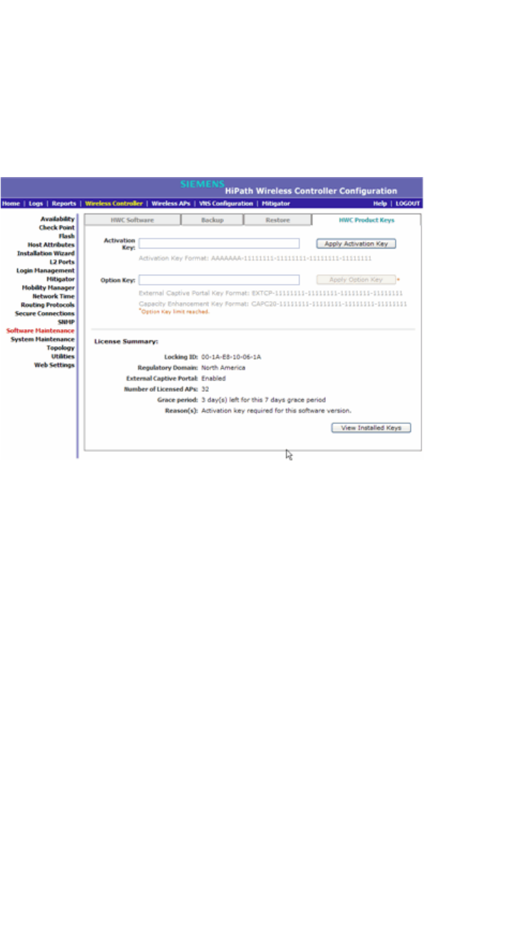
Configuring the HiPath Wireless Controller
hwc_startup.fm
Configuring the HiPath Wireless Controller for the first time
9034530-02, March 2010
54 HiPath Wireless Controller, Access Points and Convergence Software V7.11, User Guide
To install the license keys:
1. From the main menu, click Wireless Controller Configuration. The HiPath
Wireless Controller Configuration screen is displayed.
2. In the left pane, click Software Maintenance.
3. Click the HWC Product Keys tab.
The bottom pane displays the license summary.
4. If you are installing a temporary or permanent activation license key, type the
key in the Activation Key box, and then click the Apply Activation Key
button.
5. If you are installing a capacity enhancement or optional feature license key,
type the key In the Option Key box, and then click the Apply Option Key
button.
6. To view installed keys, click View Installed Keys.
3.4.3 Setting up the data ports
A new HiPath Wireless Controller is shipped from the factory with all its data ports
set up. Support of management traffic is disabled on all data ports. By default,
data interface states are enabled. A disabled interface does not allow data to flow
(receive/transmit).
Physical ports are represented by the L2 (Ethernet) Ports and associated
Topologies which are created by default when the controller is first powered up.
The L2 port and Topology information can be accessed from L2 Ports and
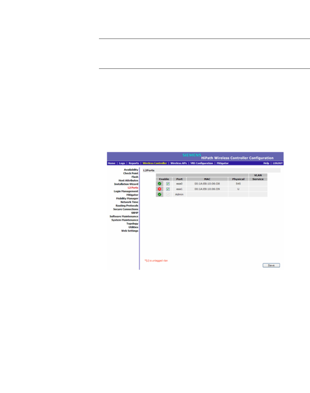
hwc_startup.fm
Configuring the HiPath Wireless Controller
Configuring the HiPath Wireless Controller for the first time
9034530-02, March 2010
HiPath Wireless Controller, Access Points and Convergence Software V7.11, User Guide 55
Topology tabs under HiPath Wireless Controller Configuration. The L2 Ports
cannot be removed from the system but their operational status can be changed
(together with a few other parameters, as explained below).
Note: You can redefine a data port to function as a Third-Party AP Port. Refer
to Section 3.4.3.2, “Viewing and changing the L2 port related topologies” for more
information.
3.4.3.1 Viewing and changing the L2 ports information
To view and change the L2 port information:
1. From the main menu, click Wireless Controller Configuration. The HiPath
Wireless Controller Configuration screen is displayed.
2. In the left pane, click L2 Ports. The L2 Ports tab is displayed.
The L2 Ports tab presents the Physical (that is, Ethernet) ports that exist on
the HiPath Wireless Controller. These ports cannot be deleted and new ones
cannot be created. The number of Ethernet ports and their names per
controller are:
•C5110 – Three data ports, displayed as esa0, esa1, and esa2.
•C4110 – Four data ports, displayed as Port1, Port2, Port3, and Port4.
•C2400 – Four data ports, displayed as esa0, esa1, esa2, and esa3.
•C20 – Two data ports, displayed as esa0 and esa1.
•C20N – Two data ports, displayed as PC.1 and PC.2.

Configuring the HiPath Wireless Controller
hwc_startup.fm
Configuring the HiPath Wireless Controller for the first time
9034530-02, March 2010
56 HiPath Wireless Controller, Access Points and Convergence Software V7.11, User Guide
•CRBT8210 – One data port, displayed as esa0.
•CRBT8110 – One data port, displayed as esa0.
Also an “Admin” port is created by default. This represents a physical port,
separate from the other data ports, being used for management connectivity.
Parameters displayed for the L2 Ports are:
•Operational status, represented graphically with a green checkmark (UP)
or red X (DOWN). This is the only configurable parameter.
•Port name, as described above.
•MAC address, as per Ethernet standard.
•VLAN ID, for different types of topology. Refer to Section 3.4.3.2, “Viewing
and changing the L2 port related topologies” for more information about
L2 port topologies.
3. If desired, change the operational status by clicking the Enable checkbox.
You can change the operational state for each port. By default, data interface
states are enabled. If they are not enabled, you can enable them individually.
A disabled interface does not allow data to flow (receive/transmit).
3.4.3.2 Viewing and changing the L2 port related topologies
Each of the L2 Ports has a predefined Topology associated with it.
To view and change the L2 port topologies:
1. From the main menu, click Wireless Controller Configuration. The HiPath
Wireless Controller Configuration screen is displayed.
2. In the left pane, click Topology. The Topologies tab is displayed.
An associated topology entry is created by default for each L2 Port with the
same name.
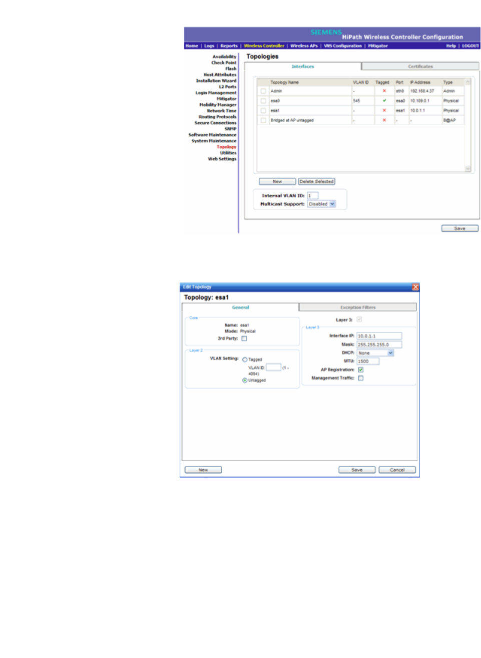
hwc_startup.fm
Configuring the HiPath Wireless Controller
Configuring the HiPath Wireless Controller for the first time
9034530-02, March 2010
HiPath Wireless Controller, Access Points and Convergence Software V7.11, User Guide 57
3. To change any of the associated parameters, click on the topology entry to
be modified. An “Edit Topology” pop up window appears.
For the data ports predefined in the system, Name and Mode are not
configurable.
4. Optionally, configure one of the physical ports for Third Party AP connectivity
by clicking the 3rd Party checkbox.
You must configure a port to which you will be connecting third-party APs by
checking this box. Only one port can be configured for third-party APs.
Third-party APs must be deployed within a segregated network for which the
HiPath Wireless Controller becomes the single point of access (i.e., routing
gateway). When you define a port as the third-party AP port, the interface
segregates the third-party AP from the remaining network.

Configuring the HiPath Wireless Controller
hwc_startup.fm
Configuring the HiPath Wireless Controller for the first time
9034530-02, March 2010
58 HiPath Wireless Controller, Access Points and Convergence Software V7.11, User Guide
5. To configure an interface for VLAN assignment, configure the VLAN Settings
in the Layer 2 box.
When you configure a HiPath Wireless Controller port to be a member of a
VLAN, you must ensure that the VLAN configuration (VLAN ID and tagged vs.
untagged attribute) is matched with the correct configuration on the network
switch.
6. If the desired IP configuration is different from the one displayed, change the
Interface IP and Mask accordingly in the Layer 3 box.
For this type of data interface, the Layer 3 check box is selected
automatically. This allows for IP Interface and subnet configuration together
with other networking services.
7. If desired, change the MTU value. This value specifies the Maximum
Transmission Unit or maximum packet size for this port. The default value is
1500 bytes for physical topologies.
If you change this setting and are using OSPF, be sure that the MTU of all the
ports in the OSPF link match.
Note: If the routed connection to an AP traverses a link that imposes a lower
MTU than the default 1500 bytes, the HiPath Wireless Controller and AP
participate in automatic MTU discovery and adjust their settings accordingly.
At the HiPath Wireless Controller, MTU adjustments are tracked on a per AP
basis.
8. To enable AP registration through this interface, select the AP Registration
checkbox.
Wireless APs use this port for discovery and registration. Other controllers
can use this port to enable inter-controller device mobility if this port is
configured to use SLP or the HiPath Wireless Controller is running as a
manager and SLP is the discovery protocol used by the agents.
9. To enable management traffic, select the Management Traffic checkbox.
Enabling management provides access to SNMP (v2, V3, get), SSH, and
HTTPs management interfaces.
Note: This option does not override the built-in protection filters on the port.
The built-in protection filters for the port, which are restrictive in the types of
packets that are allowed to reach the management plane, are extended with
a set of definitions that allow for access to system management services
through that interface (SSH, SNMP, HTTPS:5825).
10. To enable the local DHCP Server on the HiPath Wireless Controller, in the
DHCP box, select Local Server. Then, click on the Configure button to open
the DHCP configuration pop up window.
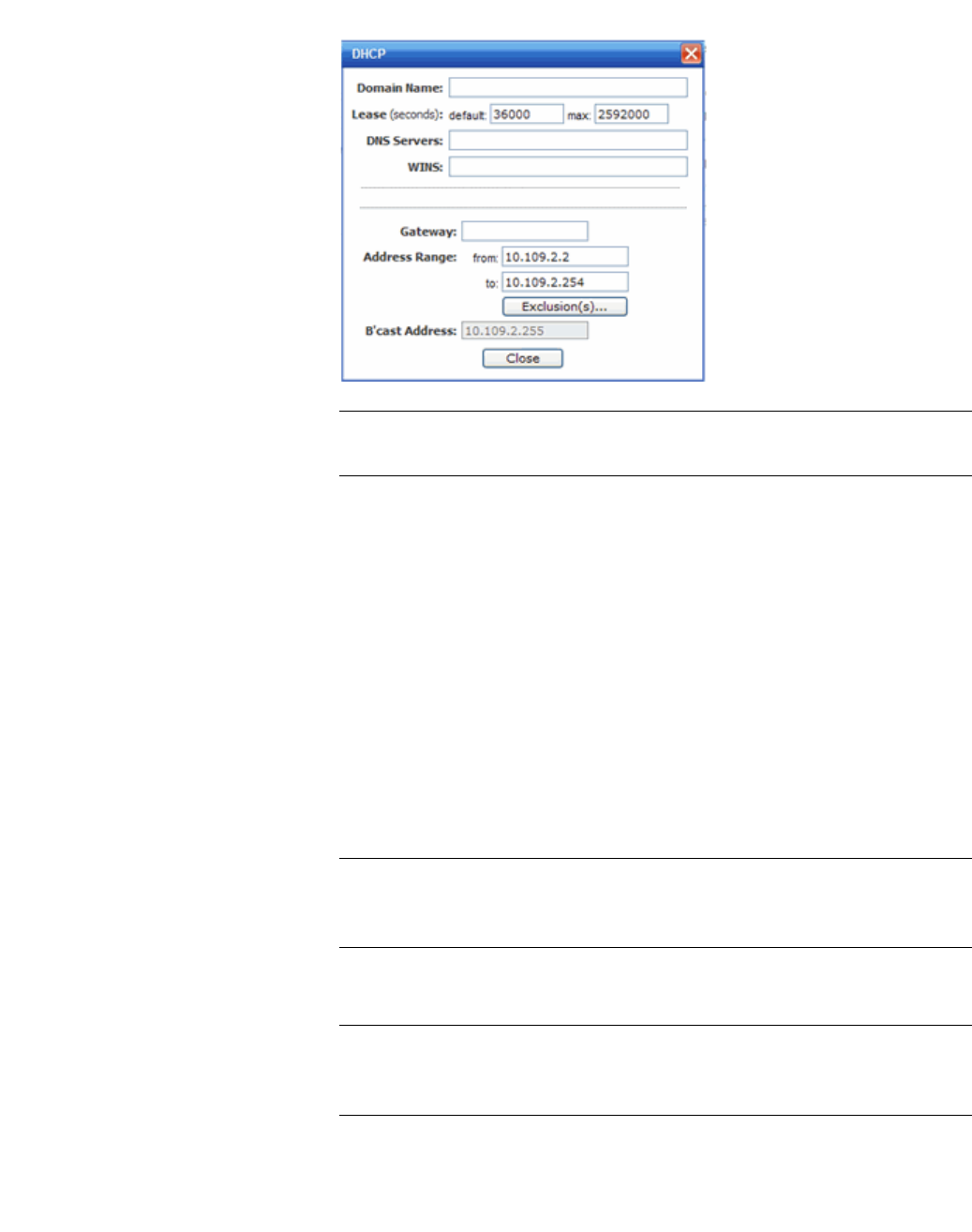
hwc_startup.fm
Configuring the HiPath Wireless Controller
Configuring the HiPath Wireless Controller for the first time
9034530-02, March 2010
HiPath Wireless Controller, Access Points and Convergence Software V7.11, User Guide 59
Note: The local DHCP Server is useful as a general purpose DHCP Server
for small subnets.
a) In the Domain Name box, type the name of the domain that you want the
Wireless APs to use for DNS Server’s discovery.
b) In the Lease (seconds) default box, type the time period for which the IP
address will be allocated to the Wireless APs (or any other device
requesting it).
c) In the Lease (seconds) max box, type the maximum time period in
seconds for which the IP address will be allocated to the Wireless APs.
d) In the DNS Servers box, type the DNS Server’s IP address if you have a
DNS Server.
e) In the WINS box, type the WINS Server’s IP address if you have a WINS
Server.
Note: You can type multiple entries in the DNS Servers and WINS boxes.
Each entry must be separate by a comma. These two fields are not
mandatory to enable the local DHCP feature.
f) In the Gateway box, type the IP address of the default gateway.
Note: Since the HiPath Wireless Controller is not allowed to be the gateway
for the segment, including Wireless APs, you cannot use the Interface IP
address as the gateway address.
g) Configure the address range from which the local DHCP Server will
allocate IP addresses to the Wireless APs.
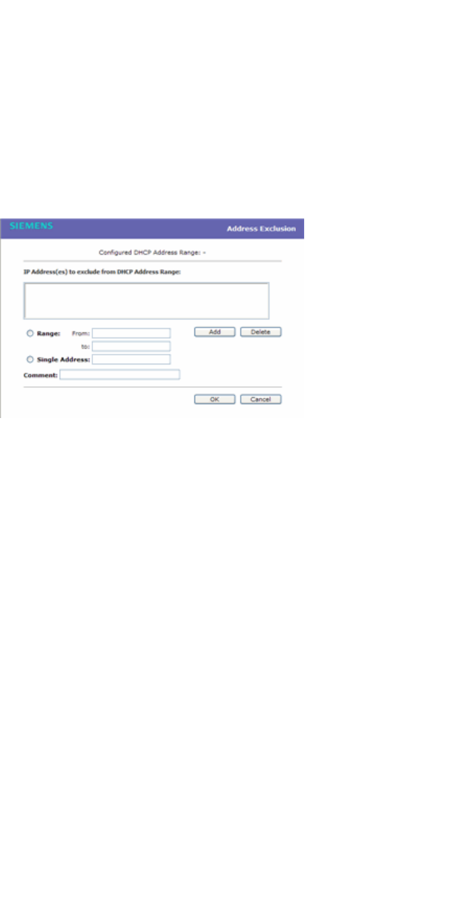
Configuring the HiPath Wireless Controller
hwc_startup.fm
Configuring the HiPath Wireless Controller for the first time
9034530-02, March 2010
60 HiPath Wireless Controller, Access Points and Convergence Software V7.11, User Guide
•In the Address Range: from box, type the starting IP address of the
IP address range.
•In the Address Range: to box, type the ending IP address of the IP
address range.
h) Click the Exclusion(s) button to exclude IP addresses from allocation by
the DHCP Server. The DHCP Address Exclusion window opens.
The HiPath Wireless Controller automatically adds the IP addresses of
the Interfaces (Ports), and the default gateway to the exclusion list. You
can not remove these IP addresses from the exclusion list.
•Select the Range radio button. In the From box, type the starting IP
address of the IP address range that you want to exclude from the
DHCP allocation.
•In the To box, type the ending IP address of the IP address range that
you want to exclude from the DHCP allocation.
•To exclude a single address, select the Single Address radio button
and type the IP address in the adjacent box.
•In the Comment box, type any relevant comment. For example, you
can type the reason for which a certain IP address is excluded from
the DHCP allocation.
•Click on Add. The excluded IP addresses are displayed in the IP
Address(es) to exclude from DHCP Address Range box.
•To delete a IP Address from the exclusion list, select it in the IP
Address(es) to exclude from DHCP Range box, and then click
Delete.
•To save your changes, click OK.
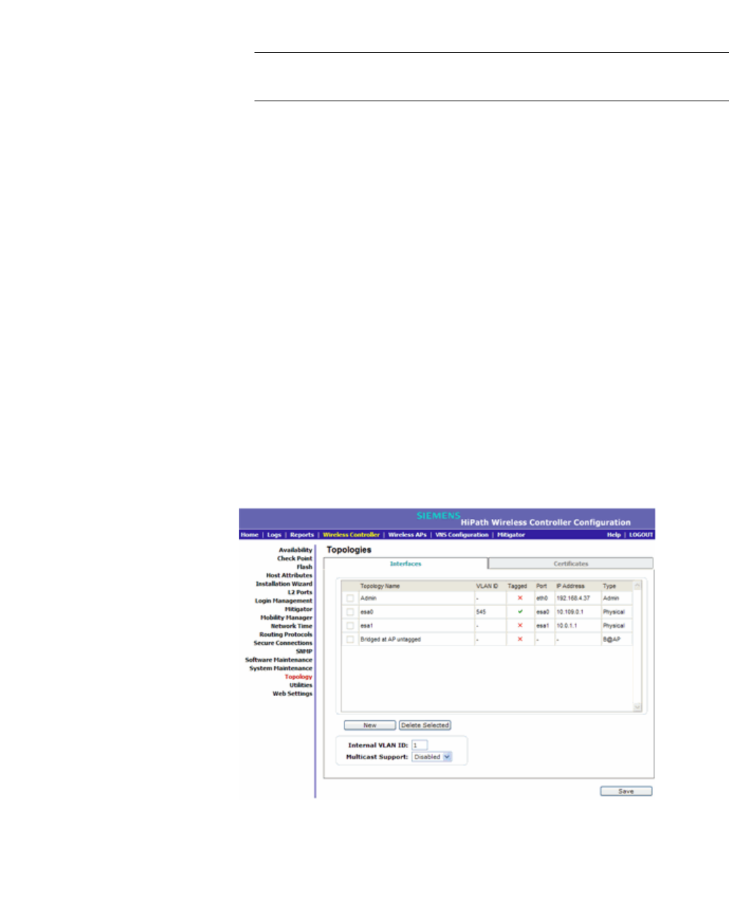
hwc_startup.fm
Configuring the HiPath Wireless Controller
Configuring the HiPath Wireless Controller for the first time
9034530-02, March 2010
HiPath Wireless Controller, Access Points and Convergence Software V7.11, User Guide 61
i) Click Close to close the DHCP configuration window.
Note: The Broadcast (B’cast) Address field is view only. This field is
computed from the mask and the IP addresses.
11. You are returned to the L2 port topology edit window.
3.4.4 Setting up Internal VLAN ID and multi-cast
support
You can configure the Internal VLAN ID, and enable multicast support. The
internal VLAN used only internally and is not visible on the external traffic. The
physical topology used for multicast is represented by a physical port to/from
which the multicast traffic is forwarded in conjunction with the virtual routed
topologies (and VNSs) configured on the controller. Please note that no multicast
routing is available at this time.
To configure the Internal VLAN ID and enable multicast support:
1. From the main menu, click Wireless Controller Configuration. The HiPath
Wireless Controller Configuration screen is displayed.
2. In the left pane, click Topology. The Topologies tab is displayed.
3. Click the Interfaces tab.
4. In the Internal VLAN ID box, type the internal VLAN ID.
5. From the Multicast Support drop-down list, select the desired data port
(physical Ethernet topology).
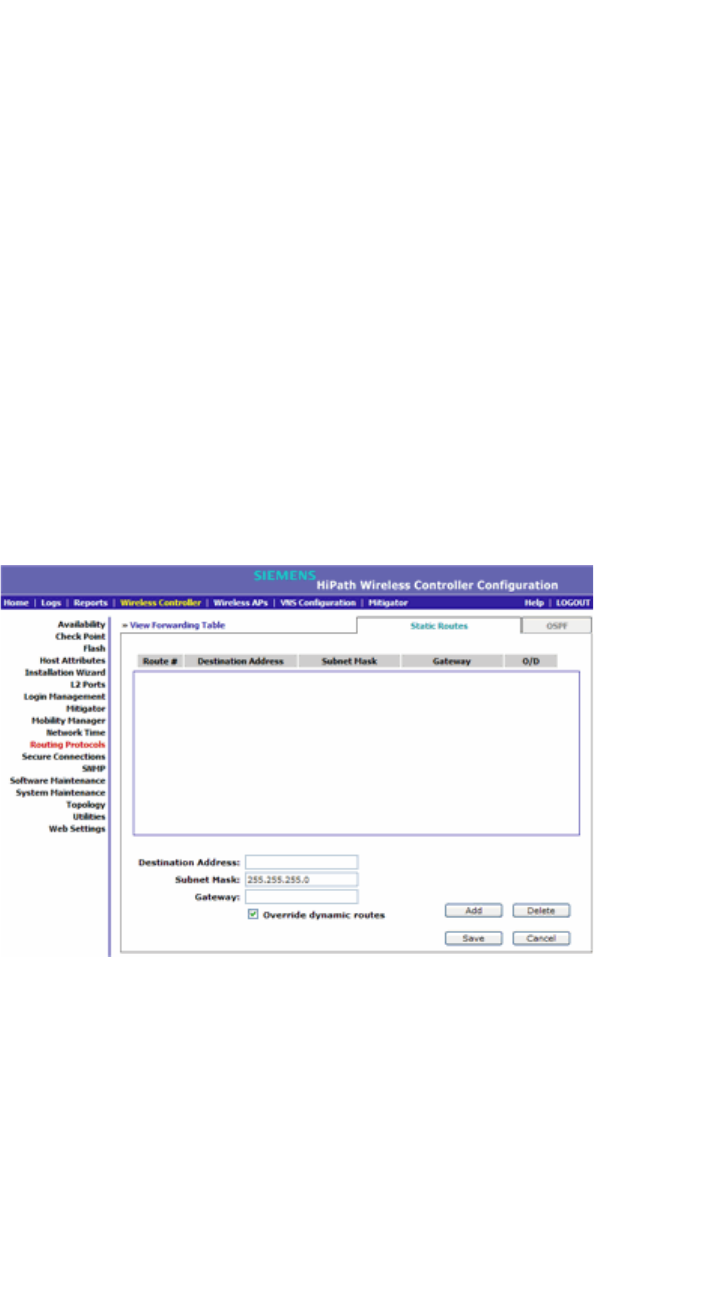
Configuring the HiPath Wireless Controller
hwc_startup.fm
Configuring the HiPath Wireless Controller for the first time
9034530-02, March 2010
62 HiPath Wireless Controller, Access Points and Convergence Software V7.11, User Guide
If you are configuring a HiPath Wireless Controller C20N, the data ports are
PC.1 and PC.2.
If you are configuring a HiPath Wireless Controller C4110, the data ports are
Port1, Port2, Port3, and Port4.
6. To save your changes, click Save.
3.4.5 Setting up static routes
It is recommended that you define a default route to your enterprise network,
either with a static route or by using the OSPF protocol. A default route enables
the HiPath Wireless Controller to forward packets to destinations that do not
match a more specific route definition.
To set a static route on the HiPath Wireless Controller:
1. From the main menu, click Wireless Controller Configuration. The HiPath
Wireless Controller Configuration screen is displayed.
2. In the left pane, click Routing Protocols. The Static Routes tab is displayed.
3. To add a new route, in the Destination Address box type the destination IP
address of a packet.
To define a default static route for any unknown address not in the routing
table, type 0.0.0.0.
4. In the Subnet Mask box, type the appropriate subnet mask to separate the
network portion from the host portion of the IP address (typically
255.255.255.0). To define the default static route for any unknown address,
type 0.0.0.0.

hwc_startup.fm
Configuring the HiPath Wireless Controller
Configuring the HiPath Wireless Controller for the first time
9034530-02, March 2010
HiPath Wireless Controller, Access Points and Convergence Software V7.11, User Guide 63
5. In the Gateway box, type the IP address of the specific router port or gateway
on the same subnet as the HiPath Wireless Controller to which to forward
these packets. This is the IP address of the next hop between the HiPath
Wireless Controller and the packet’s ultimate destination.
6. Click Add. The new route is added to the list of routes.
7. Select the Override dynamic routes checkbox to give priority over the OSPF
learned routes, including the default route, which the HiPath Wireless
Controller uses for routing. This option is enabled by default.
To remove this priority for static routes, so that routing is controlled
dynamically at all times, clear the Override dynamic routes checkbox.
Note: If you enable dynamic routing (OSPF), the dynamic routes will normally
have priority for outgoing routing. For internal routing on the HiPath Wireless
Controller, the static routes normally have priority.
8. To save your changes, click Save.
3.4.5.1 Viewing the forwarding table
You can view the defined routes, whether static or OSPF, and their current status
in the forwarding table.
To view the forwarding table on the HiPath Wireless Controller:
1. From the Routing Protocols Static Routes tab, click View Forwarding
Table. The Forwarding Table is displayed.
2. Alternatively. from the main menu, click Reports & Displays. The HiPath
Reports & Displays screen is displayed. Then, click Forwarding Table. The
Forwarding Table is displayed.
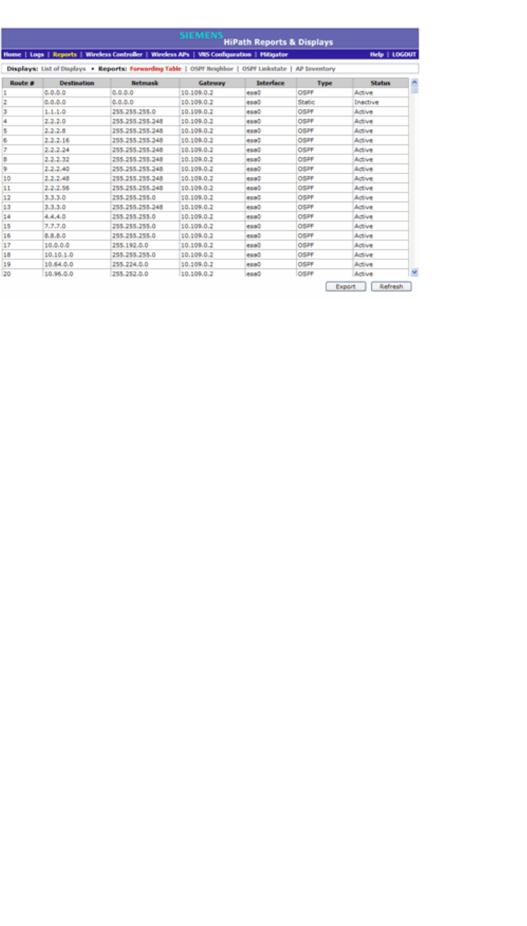
Configuring the HiPath Wireless Controller
hwc_startup.fm
Configuring the HiPath Wireless Controller for the first time
9034530-02, March 2010
64 HiPath Wireless Controller, Access Points and Convergence Software V7.11, User Guide
This report displays all defined routes, whether static or OSPF, and their
current status.
3. To update the display, click Refresh.
3.4.6 Setting up OSPF Routing
To enable OSPF (OSPF RFC2328) routing, you must:
•Specify at least one data port on which OSPF is enabled on the Port Settings
option of the OSPF tab. This is the interface on which you can establish OSPF
adjacency.
•Enable OSPF globally on the HiPath Wireless Controller
•Define the global OSPF parameters
Ensure that the OSPF parameters defined here for the HiPath Wireless Controller
are consistent with the adjacent routers in the OSPF area. This consistency
includes the following:
•If the peer router has different timer settings, the protocol timer settings in the
HiPath Wireless Controller must be changed to match, in order to achieve
OSPF adjacency.
•The MTU of the ports on either end of an OSPF link must match. The MTU
for ports on the HiPath Wireless Controller is defined as 1500, on the L2 Port
tab, during data port setup. This matches the default MTU in standard routers.
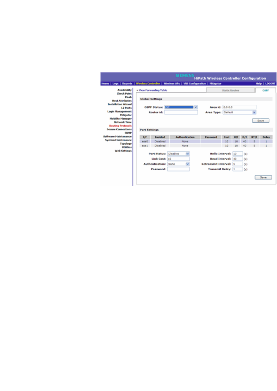
hwc_startup.fm
Configuring the HiPath Wireless Controller
Configuring the HiPath Wireless Controller for the first time
9034530-02, March 2010
HiPath Wireless Controller, Access Points and Convergence Software V7.11, User Guide 65
To set OSPF Routing Global Settings on the HiPath Wireless Controller:
1. From the main menu, click Wireless Controller Configuration. The HiPath
Wireless Controller Configuration screen is displayed.
2. In the left pane, click Routing Protocols. The Static Routes tab is displayed
by default.
3. Click the OSPF tab.
4. From the OSPF Status drop-down list, click On to enable OSPF.
In the Router ID box, type the IP address of the HiPath Wireless Controller.
This ID must be unique across the OSPF area. If left blank, the OSPF
daemon automatically picks a router ID from one of the HiPath Wireless
Controller’s interface IP addresses.
5. In the Area ID box, type the area. 0.0.0.0 is the main area in OSPF.
6. In the Area Type drop-down list, click one of the following:
• Default – The default acts as the backbone area (also known as area
zero). It forms the core of an OSPF network. All other areas are
connected to it, and inter-area routing happens via a router connected to
the backbone area.
•Stub – The stub area does not receive external routes. External routes
are defined as routes which were distributed in OSPF via another routing
protocol. Therefor, stub areas typically rely on a default route to send
traffic routes outside the present domain.
• Not-so-stubby – The not-so-stubby area is a type of stub area that can
import autonomous system (AS) external routes and send them to the
default/backbone area, but cannot receive AS external routes from the
backbone or other areas.

Configuring the HiPath Wireless Controller
hwc_startup.fm
Configuring the HiPath Wireless Controller for the first time
9034530-02, March 2010
66 HiPath Wireless Controller, Access Points and Convergence Software V7.11, User Guide
7. To save your changes, click Save.
To set OSPF Routing Port Settings on the HiPath Wireless Controller:
1. From the main menu, click Wireless Controller Configuration. The HiPath
Wireless Controller Configuration screen is displayed.
2. In the left pane, click Routing Protocols.
3. Click the OSPF tab.
4. Select a port to configure by clicking on the desired port in the Port Settings
table.
5. In the Port Status drop-down list, click Enabled to enable OSPF on the port.
The default setting is Disabled.
6. In the Link Cost box, type the OSPF standard value for your network for this
port. This is the cost of sending a data packet on the interface. The lower the
cost, the more likely the interface is to be used to forward data traffic.
Note: If more than one port is enabled for OSPF, it is important to prevent the
HiPath Wireless Controller from serving as a router for other network traffic (other
than the traffic from wireless device users on routed topologies controlled by the
HiPath Wireless Controller). For more information, see Section 6.10.2, “About
filtering rules”, on page 352.
7. In the Authentication drop-down list, click the authentication type for OSPF
on your network: None or Password. The default setting is None.
8. If Password is selected as the authentication type, in the Password box,
type the password.
If None is selected as the Authentication type, leave this box empty. This
password must match on either end of the OSPF connection.
9. Type the following:
• Hello-Interval – Specifies the time in seconds (displays OSPF
default).The default setting is 10 seconds.
• Dead-Interval – Specifies the time in seconds (displays OSPF default).
The default setting is 40 seconds.
• Retransmit-Interval – Specifies the time in seconds (displays OSPF
default). The default setting is 5 seconds.
• Transmit Delay– Specifies the time in seconds (displays OSPF default).
The default setting is 1 second.
10. To save your changes, click Save.

hwc_startup.fm
Configuring the HiPath Wireless Controller
Configuring the HiPath Wireless Controller for the first time
9034530-02, March 2010
HiPath Wireless Controller, Access Points and Convergence Software V7.11, User Guide 67
To confirm that ports are set for OSPF:
1. To confirm that the ports are set up for OSPF, and that advertised routes from
the upstream router are recognized, click View Forwarding Table. The
Forwarding Table is displayed.
The following additional reports display OSPF information when the protocol
is in operation:
• OSPF Neighbor – Displays the current neighbors for OSPF (routers that
have interfaces to a common network)
• OSPF Linkstate – Displays the Link State Advertisements (LSAs)
received by the currently running OSPF process. The LSAs describe the
local state of a router or network, including the state of the router’s
interfaces and adjacencies.
2. To update the display, click Refresh.
3.4.7 Configuring filtering at the interface level
The HiPath Wireless solution has a number of built-in filters that protect the
system from unauthorized traffic. These filters are specific only to the HiPath
Wireless Controller. These filters are applied at the network interface level and
are automatically invoked. By default, these filters provide stringent-level rules to
allow only access to the system's externally visible services. In addition to these
built-in filters, the administrator can define specific exception filters at the
interface-level to customize network access. These filters depend on Topology
Modes and the configuration of an L3 interface for the topology.
For Bridged at Controller topologies, exception filters are defined only if L3 (IP)
interfaces are specified. For Physical, Routed, and 3rd Party AP topologies,
exception filtering is always configured since they all have an L3 interface
presence.
3.4.7.1 Built-in interface-based exception filters
On the HiPath Wireless Controller, various interface-based exception filters are
built in and invoked automatically. These filters protect the HiPath Wireless
Controller from unauthorized access to system management functions and
services via the interfaces. Access to system management functions is granted if
the administrator selects the allow management traffic option in a specific
topology.
Allow management traffic is possible on the topologies that have L3 IP interface
definitions. For example, if management traffic is allowed on a physical topology
(esa0), only users connected through ESA0 will be able to get access to the
system. Users connecting on any other topology, such as Routed or Bridged

Configuring the HiPath Wireless Controller
hwc_startup.fm
Configuring the HiPath Wireless Controller for the first time
9034530-02, March 2010
68 HiPath Wireless Controller, Access Points and Convergence Software V7.11, User Guide
Locally at Controller, will no longer be able to target ESA0 to gain management
access to the system. In order to allow access for users connected on such a
topology, the given topology configuration itself must have allow management
traffic enabled and users will only be able to target the topology interface
specifically.
On the HiPath Wireless Controller’s L3 interfaces (associated with either
physical, Routed, or Bridged Locally at Controller topologies), the built-in
exception filter prohibits invoking SSH, HTTPS, or SNMP. However, such traffic
is allowed, by default, on the management port.
If management traffic is explicitly enabled for any interface, access is implicitly
extended to that interface through any of the other interfaces (VNS). Only traffic
specifically allowed by the interface’s exception filter is allowed to reach the
HiPath Wireless Controller itself. All other traffic is dropped. Exception filters are
dynamically configured and regenerated whenever the system's interface
topology changes (for example, a change of IP address for any interface).
Enabling management traffic on an interface adds additional rules to the
exception filter, which opens up the well-known IP(TCP/UDP) ports,
corresponding to the HTTPS, SSH, and SNMP applications.
The interface-based built-in exception filtering rules, in the case of traffic from
wireless users, are applicable to traffic targeted directly for the topology L3
interface. For example, a filter specified by a Policy may be generic enough to
allow traffic access to the HiPath Wireless Controller's management (for
example, Allow All [*.*.*.*]). Exception filter rules are evaluated after the user's
assigned filter policy, as such, it is possible that the policy allows the access to
management functions that the exception filter denies. These packets are
dropped.
To enable SSH, HTTPS, or SNMP access through a physical data interface:
1. From the main menu, click Wireless Controller Configuration. The HiPath
Wireless Controller Configuration screen is displayed.
2. In the left pane, click Topology. The Topologies tab is displayed.
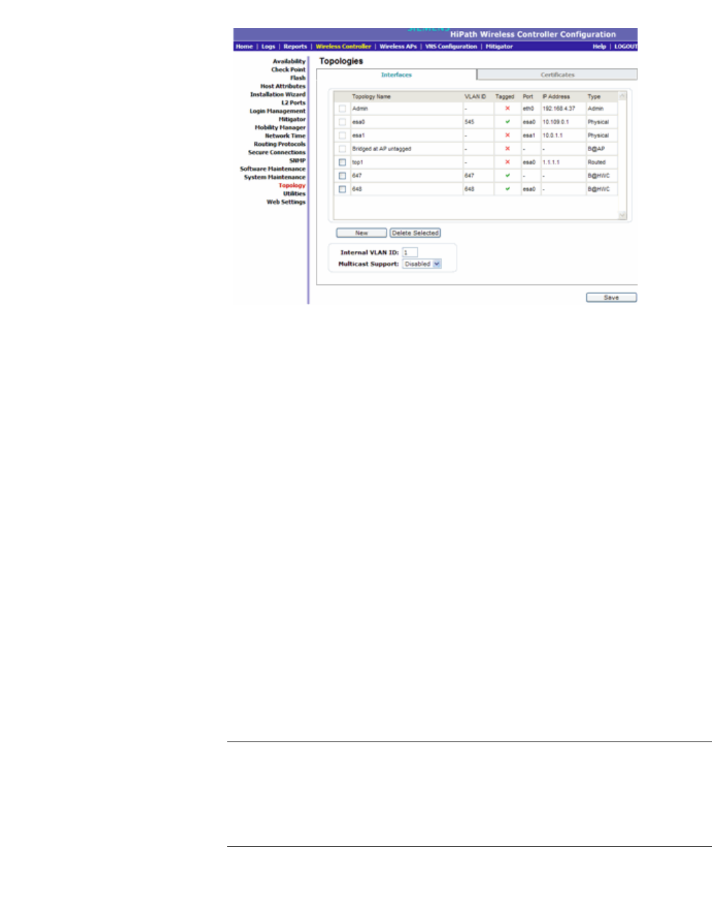
hwc_startup.fm
Configuring the HiPath Wireless Controller
Configuring the HiPath Wireless Controller for the first time
9034530-02, March 2010
HiPath Wireless Controller, Access Points and Convergence Software V7.11, User Guide 69
3. On the Interfaces tab, click the appropriate data port topology. The Edit
Topology window displays.
4. Select the Management Traffic checkbox if the topology has specified an L3
IP interface presence.
5. To save your changes, click Save.
3.4.7.2 Working with administrator-defined interface-based
exception filters
You can add specific filtering rules at the interface level in addition to the built-in
rules. Such rules give you the capability of restricting access to a port, for specific
reasons, such as a Denial of Service (DoS) attack.
The filtering rules are set up in the same manner as filtering rules defined for a
Policy — specify an IP address, select a protocol if applicable, and then either
allow or deny traffic to that address. For more information, see Section 6.10.2,
“About filtering rules”, on page 352.
The rules defined for port exception filters are prepended to the normal set of
restrictive exception filters and have precedence over the system's normal
protection enforcement (that is, they are evaluated first).
Warning: If defined improperly, user exception rules may seriously compromise
the system’s normal security enforcement rules. They may also disrupt the
system's normal operation and even prevent system functionality altogether. It is
advised to only augment the exception-filtering mechanism if absolutely
necessary.
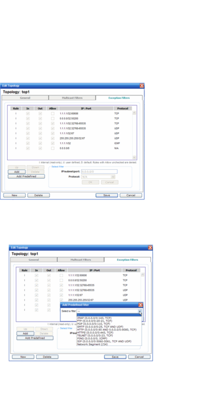
Configuring the HiPath Wireless Controller
hwc_startup.fm
Configuring the HiPath Wireless Controller for the first time
9034530-02, March 2010
70 HiPath Wireless Controller, Access Points and Convergence Software V7.11, User Guide
To define interface exception filters:
1. From the main menu, click Wireless Controller Configuration. The HiPath
Wireless Controller Configuration screen is displayed.
2. In the left pane, click Topology. The Topologies screen is displayed.
3. Select a topology to be configured. The Edit Topology window is displayed.
4. If the topology has an L3 interface defined, an Exception Filters tab is
available. Select this tab. The Exception Filter rules are displayed.
5. Add rules by either:
•Clicking the Add Predefined button, selecting a filter from the drop down
list, and clicking Add.
•Clicking the Add button, filling in the following fields, then clicking OK:

hwc_startup.fm
Configuring the HiPath Wireless Controller
Configuring the HiPath Wireless Controller for the first time
9034530-02, March 2010
HiPath Wireless Controller, Access Points and Convergence Software V7.11, User Guide 71
a) In the IP / subnet:port box, type the destination IP address. You can
also specify an IP range, a port designation, or a port range on that IP
address.
b) In the Protocol drop-down list, click the protocol you want to specify
for the filter. This list may include UDP, TCP, GRE, IPsec-ESP, IPsec-
AH, ICMP. The default is N/A.
6. The new filter is displayed in the upper section of the screen.
7. Click the new filter entry.
8. To allow traffic, select the Allow checkbox.
9. To adjust the order of the filtering rules, click Up or Down to position the rule.
The filtering rules are executed in the order defined here.
10. To save your changes, click Save.
3.4.8 Installing certificates on the HiPath Wireless
Controller
You can install certificates on the HiPath Wireless Controller that help secure the
HiPath Wireless Controller’s interfaces and internal Captive Portal pages.
The Interface certificates are actually associated with Topologies that have
configured a L3 (IP) interface. For simplicity, they will be called Interface
certificates in this document.
Factory default certificate
By default, the HiPath Wireless Controller is shipped with a self-signed certificate.
The self-signed certificate does the following:
•Protects all interfaces that provide administrative access to the HiPath
Wireless Controller
•Protects the internal Captive Portal page
If you chose to use the default certificate to secure the HiPath Wireless Controller
and internal Captive Portal page, your Web browser will likely continue to produce
security warnings regarding the security risks of trusting self-signed certificates.
To avoid the certificate-related Web browser security warnings, you can install
customized certificates on the HiPath Wireless Controller.
Note: To avoid the certificate-related Web browser security warnings when
accessing the HiPath Wireless Assistant, you must also import the customized
certificates into your Web browser application.

Configuring the HiPath Wireless Controller
hwc_startup.fm
Configuring the HiPath Wireless Controller for the first time
9034530-02, March 2010
72 HiPath Wireless Controller, Access Points and Convergence Software V7.11, User Guide
Certificate format
The HiPath Wireless Controller supports the PKCS#12 certificate format. The
PKCS#12 certificate (.pfx) file contains both a certificate and the corresponding
private key.
Certificate monitoring
The HiPath Wireless Controller monitors the expiration date of installed
certificates. The HiPath Wireless Controller generates an entry in the events
information log as the certificate expiry date approaches, based on the following
schedule: 15, 8, 4, 2, and 1 day prior to expiration. The log messages cease when
the certificate expires. For more information, see the HiPath Wireless Controller,
Access Points and Convergence Software Maintenance Guide.
Upgrades and migrations
Installed certificates will be backed up and restored with the HiPath Wireless
Controller configuration data. Installed certificates will also be migrated during an
upgrade and during a migration.
Prerequisite for installing a certificate
You can chose your preferred CA to generate the PKCS#12 file. The HiPath
Wireless Controller will accept the PKCS#12 file as long as the format of the
private key and certificate are valid.
When generating the PKCS#12 certificate file, you must ensure that the interface
identified in the certificate corresponds to the HiPath Wireless Controller’s
interface for which the certificate is being installed.
Certificate Common Name
In order to avoid getting security warnings, the common name of the certificate
should match the interface IP (port IP or Topology gateway IP) that the WLAN
service uses.
• HiPath Wireless Controller ports (pcX, esaX, and eth0) – Physical
interface IP address
• Internal Captive Portal – VNS gateway IP address.
3.4.8.1 Installing a certificate for a HiPath Wireless Controller
interface
To install a certificate for a HiPath Wireless Controller data interface:
1. From the main menu, click Wireless Controller Configuration. The
Wireless Controller Configuration screen is displayed.
2. In the left pane, click Topology. The Topologies tab is displayed.
3. Click the Certificates tab.
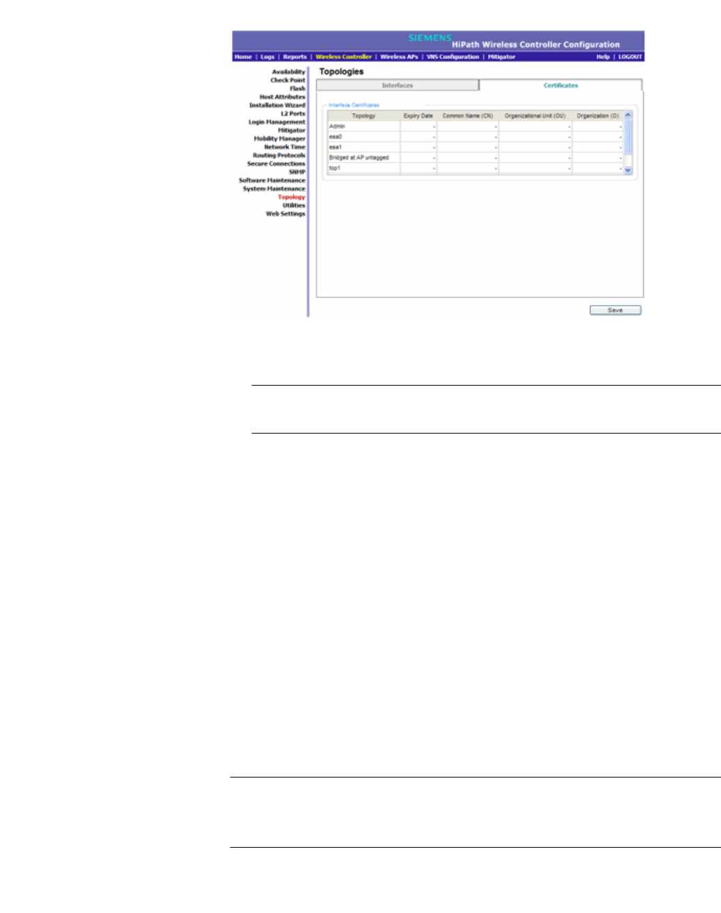
hwc_startup.fm
Configuring the HiPath Wireless Controller
Configuring the HiPath Wireless Controller for the first time
9034530-02, March 2010
HiPath Wireless Controller, Access Points and Convergence Software V7.11, User Guide 73
4. In the Interface Certificates table, click the topology (which has an L3
interface) for which you want to install a certificate.
Note: The interface identified in the certificate must correspond to the HiPath
Wireless Controller’s interface for which the certificate is being installed.
5. In the Configuration for Topology section, select one of the following:
• Replace selected Topology’s certificate and key – Select to replace
the existing port’s certificate and key, and then do the following:
a) Click Browse. The Choose file dialog is displayed.
b) Navigate to the .pfx certificate file you want to install for this port, and
then click Open. The certificate .pfx file name is displayed in the
PKCS #12 file box.
c) In the Password box, type the password for the certificate file. The
PKCS#12 file is password protected.
• Reset selected Topology to the factory default certificate and key –
Select to assign the factory default certificate and key to the interface.
6. To save your changes, click Save. A message in the footer will be displayed
to confirm if the certificate installation is successful or fails.
Note: To avoid the certificate-related Web browser security warnings when
accessing the HiPath Wireless Assistant, you must also import the customized
certificates into your Web browser application.

Configuring the HiPath Wireless Controller
hwc_startup.fm
Configuring the HiPath Wireless Controller for the first time
9034530-02, March 2010
74 HiPath Wireless Controller, Access Points and Convergence Software V7.11, User Guide
3.4.9 Configuring the login authentication mode
You can configure either local login authentication mode or the RADIUS login
authentication mode to authenticate user login attempts. Local login
authentication mode uses locally configured login credentials and passwords,
while RADIUS login authentication mode uses a RADIUS server to authenticate
user login attempts.
Note: The HiPath Wireless Controller, Access Points and Convergence Software
enables you to recover the HiPath Wireless Controller via the Rescue mode if
you have lost its login password. For more information, see the HiPath Wireless
Controller, Access Points and Convergence Software Maintenance Guide.
3.4.9.1 Configuring the local login authentication mode and
adding new users
Local login authentication mode is enabled by default. If the login authentication
was previously set to RADIUS authentication mode, you can change it to the local
authentication. You can also add new users and assign them to a login group —
as full administrators, read-only administrators, or as a GuestPortal managers.
For more information, see Section 12.2, “Defining HiPath Wireless Assistant
administrators and login groups”, on page 453
To configure the local login authentication mode:
1. From the main menu, click Wireless Controller Configuration. The
Wireless Controller Configuration screen is displayed.
2. In the left pane, click Login Management. The Login Management screen
is displayed.
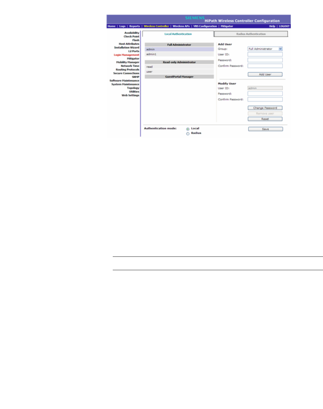
hwc_startup.fm
Configuring the HiPath Wireless Controller
Configuring the HiPath Wireless Controller for the first time
9034530-02, March 2010
HiPath Wireless Controller, Access Points and Convergence Software V7.11, User Guide 75
3. In the Authentication mode section, select Local.
4. In the Add User section, select one of the following:
• Full Administrator – Grants the administrator’s access rights to the
administrator.
• Read-only Administrator – Grants read-only access right to the
administrator.
• GuestPortal Manager – Grants the user GuestPortal manager rights.
5. In the User ID box, type the user’s ID.
6. In the Password box, type the user’s password.
Note: The password must be 8 to 24 characters long.
7. In the Confirm Password box, re-type the password.
8. To add the user, click Add User. The new user is added.

Configuring the HiPath Wireless Controller
hwc_startup.fm
Configuring the HiPath Wireless Controller for the first time
9034530-02, March 2010
76 HiPath Wireless Controller, Access Points and Convergence Software V7.11, User Guide
3.4.9.2 Configuring the RADIUS login authentication mode
The local login authentication mode is enabled by default. You can change the
local login authentication mode to RADIUS-based authentication.
Note: Before you change the default local login authentication to RADIUS-based
authentication, you must configure the RADIUS Server on the Global Settings
screen. For more information, see Section 6.2, “VNS global settings”, on page
245.
RADIUS is a client/server authentication and authorization access protocol used
by a network access server (NAS) to authenticate users attempting to connect to
a network device. The NAS functions as a client, passing user information to one
or more RADIUS servers. The NAS permits or denies network access to a user
based on the response it receives from one or more RADIUS servers. RADIUS
uses User Datagram Protocol (UDP) for sending the packets between the
RADIUS client and server.
You can configure a RADIUS key on the client and server. If you configure a key
on the client, it must be the same as the one configured on the RADIUS servers.
The RADIUS clients and servers use the key to encrypt all RADIUS packets
transmitted. If you do not configure a RADIUS key, packets are not encrypted.
The key itself is never transmitted over the network.
Note: Before you configure the system to use RADIUS-based login
authentication, you must configure the Service-Type RADIUS attribute on the
RADIUS server. For more information, see the RADIUS-based login
authentication section in the HiPath Wireless Controller, Access Points and
Convergence Software Technical Reference Guide.
To configure the RADIUS login authentication mode:
1. From the main menu, click Wireless Controller Configuration. The
Wireless Controller Configuration screen is displayed.
2. In the left pane, click Login Management. The Login Management screen
is displayed.
3. Click the RADIUS Authentication tab.
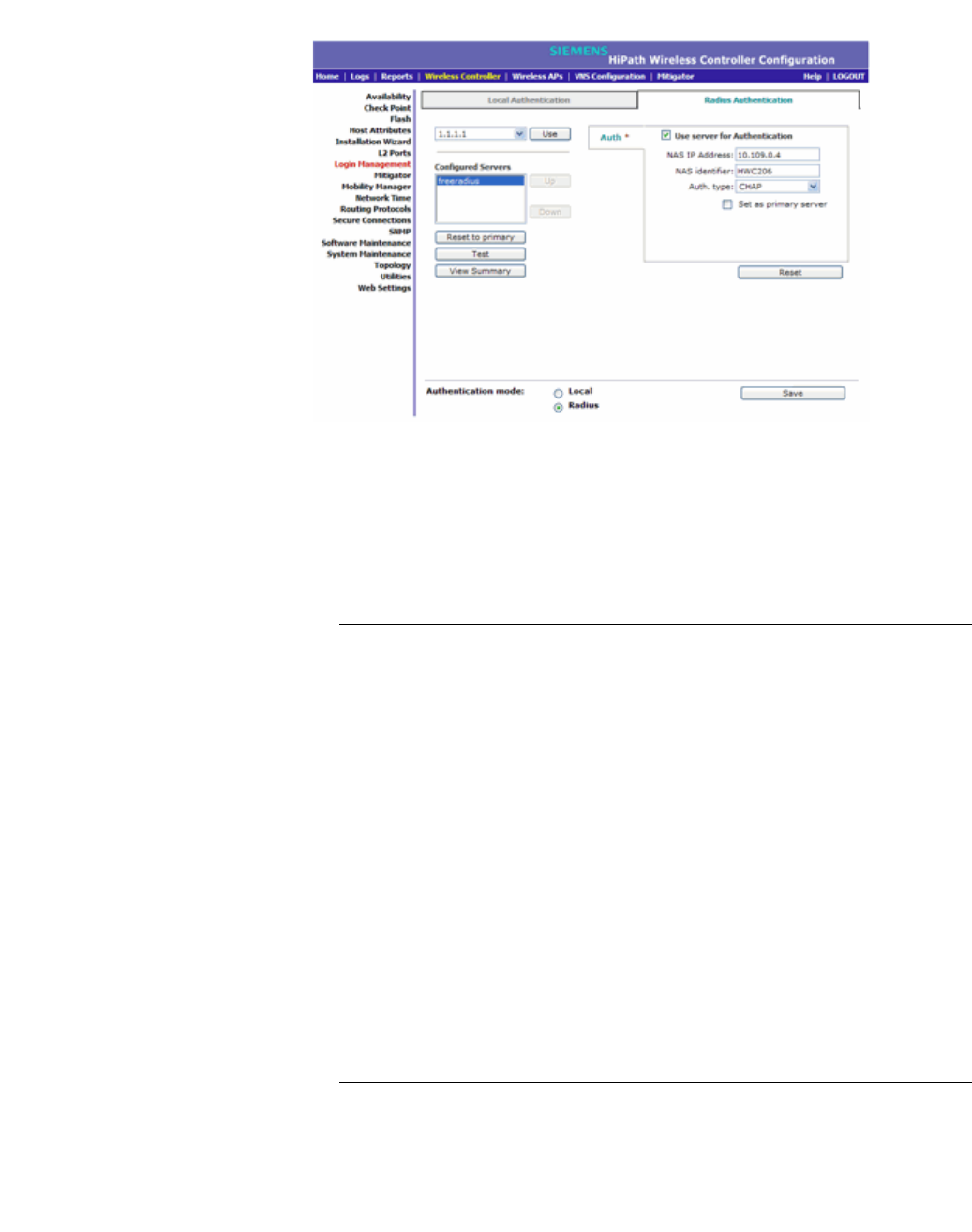
hwc_startup.fm
Configuring the HiPath Wireless Controller
Configuring the HiPath Wireless Controller for the first time
9034530-02, March 2010
HiPath Wireless Controller, Access Points and Convergence Software V7.11, User Guide 77
4. In the Authentication mode section, select Radius.
5. From the drop-down list, located next to the Use button, select the RADIUS
Server that you want to use for the RADIUS login authentication, and then
click Use. The RADIUS Server’s name is displayed in the Configured
Servers box, and in the Auth section, and the following default values of the
RADIUS Server are displayed.
Note: The RADIUS Servers displayed in the list located against the Use
button are defined on Global Settings screen. For more information, see
Section 6.2, “VNS global settings”, on page 245.
The following values can be edited:
• NAS IP address – The IP address of Network Access Server (NAS).
• NAS Identifier – The Network Access Server (NAS) identifier. The NAS
identifier is a RADIUS attribute that identifies the server responsible for
passing information to designated RADIUS servers, and then acting on
the response returned.
• Auth Type – The authentication protocol type, whether PAP or CHAP.
• Set as Primary Server – Specifies the Primary RADIUS Server when
there are multiple RADIUS servers.
6. To add additional RADIUS servers, repeat Step 5 above.
Note: You can add up to three RADIUS servers to the list of login
authentication servers. When you add two or more RADIUS Servers to the
list, you must designate one of them as the Primary server. The HiPath
Wireless Controller first attempts to connect to the Primary Server. If the
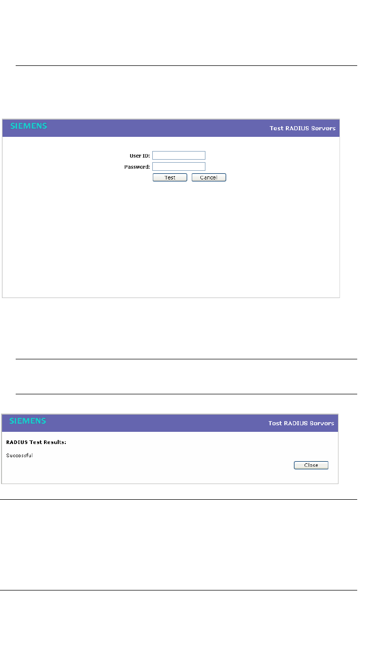
Configuring the HiPath Wireless Controller
hwc_startup.fm
Configuring the HiPath Wireless Controller for the first time
9034530-02, March 2010
78 HiPath Wireless Controller, Access Points and Convergence Software V7.11, User Guide
Primary Server is not available, it tries to connect to the second and third
server according to their order in the Configured Servers box. You can
change the order of RADIUS servers in the Configured Servers box by
clicking on the Up and Down buttons.
7. To test connectivity to the RADIUS Server, click Test. The following window
is displayed.
8. In the User ID and the Password boxes, type the user’s ID and the
password, which were configured on the RADIUS Server, and then click Test.
The RADIUS connectivity result is displayed.
Note: To learn how to configure the User ID and the Password on the
RADIUS Server, refer to your RADIUS Server’s user guide.
.
Note: After configuring the RADIUS-based login authentication mode, you must
always test the connectivity to RADIUS Server as explained in Step 7 and 8. If
you do not test the RADIUS Server connectivity, and you have made an error in
configuring the RADIUS-based login authentication mode, you will be locked out
of the HiPath Wireless Controller when you switch the login mode to the RADIUS
login authentication mode.

hwc_startup.fm
Configuring the HiPath Wireless Controller
Configuring the HiPath Wireless Controller for the first time
9034530-02, March 2010
HiPath Wireless Controller, Access Points and Convergence Software V7.11, User Guide 79
9. If the RADIUS connectivity test displays ‘Successful’ result, you must click
Save on the RADIUS Authentication screen (as depicted in Step 4) to save
your configuration.
After you save your changes, you will be logged out of the HiPath Wireless
Controller. You must use the RADIUS login user name and password to log
on the HiPath Wireless Controller.
3.4.10 Configuring network time
You should synchronize the clocks of the HiPath Wireless Controller and the
Wireless APs to ensure that the logs and reports reflect accurate time stamps.
For more information, see Chapter 11, “Working with reports and displays”.
The normal operation of the HiPath Wireless Controller will not be affected if you
do not synchronize the clock. The clock synchronization is necessary to ensure
that the logs display accurate time stamps. In addition, clock synchronization of
network elements is a prerequisite for the following configuration:
•Mobility Manager
•Session Availability
Network time synchronization
Network time is synchronized in one of two ways:
•Using the system’s time – The system’s time is the HiPath Wireless
Controller’s time.
•Using Network Time Protocol (NTP) – The Network Time Protocol is a
protocol for synchronizing the clocks of computer systems over
packet-switched data networks.
Note: If the HiPath Wireless Controller C2400 is left powered-down for more than
78 hours. In such a case, you must synchronize the network time, using the NTP
server. If the NTP server is not reachable, you must manually set the system to
the correct time.
The HiPath Wireless Controller automatically adjusts for any time change due to
Daylight Savings time.
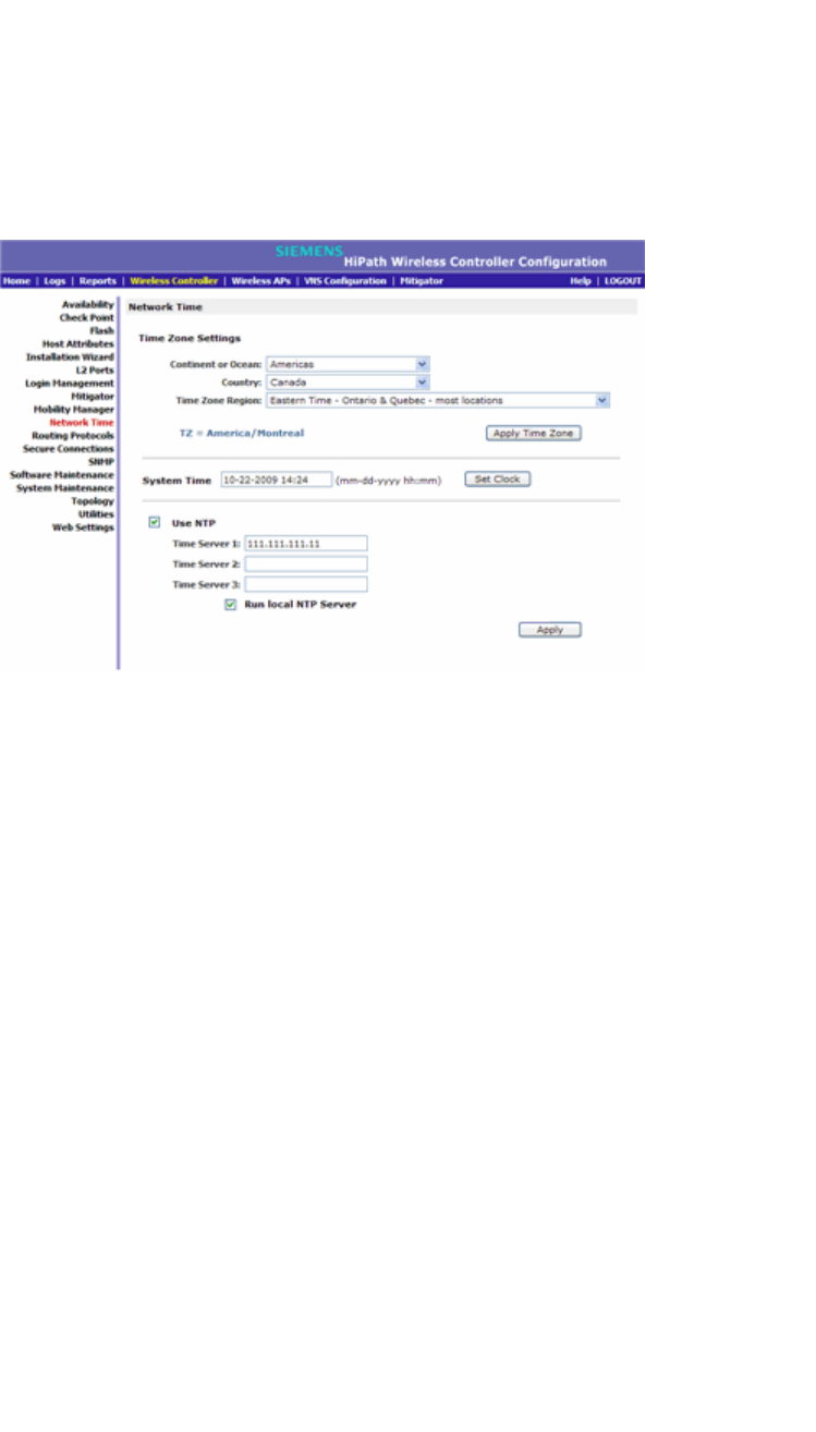
Configuring the HiPath Wireless Controller
hwc_startup.fm
Configuring the HiPath Wireless Controller for the first time
9034530-02, March 2010
80 HiPath Wireless Controller, Access Points and Convergence Software V7.11, User Guide
3.4.10.1 Configuring the network time using the system’s time
To configure the network time, using the system’s time:
1. From the main menu, click Wireless Controller Configuration. The
Wireless Controller Configuration screen is displayed.
2. In the left pane, click Network Time. The Network Time screen is displayed.
3. From the Continent or Ocean drop-down list, click the appropriate
large-scale geographic grouping for the time zone.
4. From the Country drop-down list, click the appropriate country for the time
zone. The contents of the drop-down list change, based on the selection in
the Continent or Ocean drop-down list.
5. From the Time Zone Region drop-down list, click the appropriate time zone
region for the selected country.
6. Click Apply Time Zone.
7. In the System Time box, type the system time.
8. Click Set Clock.
9. The WLAN network time is synchronized in accordance with the HiPath
Wireless Controller’s time.
3.4.10.2 Configuring the network time using an NTP server
To configure the network time using an NTP server:
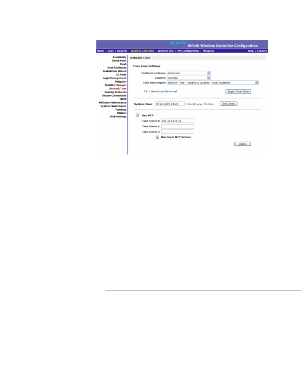
hwc_startup.fm
Configuring the HiPath Wireless Controller
Configuring the HiPath Wireless Controller for the first time
9034530-02, March 2010
HiPath Wireless Controller, Access Points and Convergence Software V7.11, User Guide 81
1. From the main menu, click Wireless Controller Configuration. The
Wireless Controller Configuration screen is displayed.
2. In the left pane, click Network Time. The Network Time screen is displayed.
3. From the Continent or Ocean drop-down list, click the appropriate
large-scale geographic grouping for the time zone.
4. From the Country drop-down list, click the appropriate country for the time
zone. The contents of the drop-down list change, based on the selection in
the Continent or Ocean drop-down list.
5. From the Time Zone Region drop-down list, click the appropriate time zone
region for the selected country.
6. Click Apply Time Zone.
7. In the System Time box, type the system time.
8. Select the Use NTP checkbox.
Note: If you want to use the HiPath Wireless Controller as the NTP Server,
select the Run local NTP Server checkbox, and then skip to Step 11.
9. In the Time Server 1 text box, type the IP address or FQDN (Full Qualified
Domain Name) of an NTP time server that is accessible on the enterprise
network.
10. Repeat for Time Server2 and Time Server3 text boxes.
If the system is not able to connect to the Time Server 1, it will attempt to
connect to the additional servers that have been specified in Time Server 2
and Time Server 3 text boxes.

Configuring the HiPath Wireless Controller
hwc_startup.fm
Configuring the HiPath Wireless Controller for the first time
9034530-02, March 2010
82 HiPath Wireless Controller, Access Points and Convergence Software V7.11, User Guide
11. Click Apply.
12. The WLAN network time is synchronized in accordance with the specified
time server.
3.4.11 Configuring DNS servers for resolving host
names of RADIUS servers
Since the Global Settings screen (Main Menu > Virtual Network
Configuration > Global Settings) allows you to set up RADIUS servers by
defining their host names, you have to configure your DNS servers to resolve the
host names of RADIUS servers to the corresponding IP addresses.
Note: For more information on RADIUS server configuration, see Section 6.2.1,
“Defining RADIUS servers and MAC address format”, on page 247.
You can configure up to three DNS servers to resolve RADIUS server host names
to their corresponding IP addresses.
The HiPath Wireless Controller sends the host name query to the first DNS server
in the stack of three configured DNS servers. The DNS server resolves the
queried domain name to an IP address and sends the result back to the HiPath
Wireless Controller.
If for some reason, the first DNS server in the stack of configured DNS servers is
not reachable, the HiPath Wireless Controller sends the host name query to the
second DNS server in the stack. If the second DNS server is also not reachable,
the query is sent to the third DNS server in the stack.
To configure DNS servers for resolving host names of RADIUS servers:
1. From the main menu, click Wireless Controller Configuration. The
Wireless Controller Configuration screen is displayed.
2. In the left pane, click Host Attributes. The Host Attributes screen is
displayed.

hwc_startup.fm
Configuring the HiPath Wireless Controller
Additional ongoing operations of the system
9034530-02, March 2010
HiPath Wireless Controller, Access Points and Convergence Software V7.11, User Guide 83
3. In the DNs box, type the DNS server’s IP address in the Server Address field
and then click Add Server. The new server is displayed in the DNS servers’
list.
Note: You can configure up to three DNS servers.
4. To save your changes, click Save.
3.5 Additional ongoing operations of the system
Ongoing operations of the HiPath Wireless Controller, Access Points and
Convergence Software system can include the following:
•HiPath Wireless Controller System Maintenance
•Wireless AP Maintenance
•Client Disassociate
•Logs and Traces
•Reports and Displays
For more information, see Chapter 12, “Performing system administration” or the
HiPath Wireless Controller, Access Points and Convergence Software
Maintenance Guide.

Configuring the HiPath Wireless Controller
hwc_startup.fm
Additional ongoing operations of the system
9034530-02, March 2010
84 HiPath Wireless Controller, Access Points and Convergence Software V7.11, User Guide

hwc_apstartup.fm
9034530-02, March 2010
HiPath Wireless Controller, Access Points and Convergence Software V7.11, User Guide 85
Configuring the Wireless AP
Wireless AP overview
4 Configuring the Wireless AP
This chapter describes the Wireless access point (AP) and its role in the
Controller, Access Points and Convergence Software solution, including:
•Wireless AP overview
•Discovery and registration overview
•Configuring the Wireless APs for the first time
•Adding and registering a Wireless AP manually
•Configuring Wireless AP settings
•Configuring the default Wireless AP settings
•Modifying a Wireless AP’s properties based on a default AP configuration
•Modifying the Wireless AP’s default setting using the Copy to Defaults feature
•Configuring Wireless APs simultaneously
•Configuring an AP as a sensor
•Performing Wireless AP software maintenance
4.1 Wireless AP overview
The Wireless AP uses the 802.11 wireless standards (802.11a/b/g/n) for network
communications and bridges network traffic to an Ethernet LAN. The Wireless AP
runs proprietary software that allows it to communicate only with the HiPath
Wireless Controller.
The Wireless AP physically connects to a LAN infrastructure and establishes an
IP connection to the HiPath Wireless Controller, which manages the Wireless AP
configuration through the HiPath Wireless Assistant. The HiPath Wireless
Controller also provides centralized management (verification and upgrade) of
the Wireless AP firmware image.
A UDP-based protocol enables communication between the Wireless AP and the
HiPath Wireless Controller. The UDP-based protocol encapsulates IP traffic from
the Wireless AP and directs it to the HiPath Wireless Controller. The HiPath
Wireless Controller decapsulates the packets and routes them to the appropriate
destinations, while managing sessions and applying policies.

Configuring the Wireless AP
hwc_apstartup.fm
Wireless AP overview
9034530-02, March 2010
86 HiPath Wireless Controller, Access Points and Convergence Software V7.11, User Guide
Deploying a Wireless AP with external antennas
Some Wireless AP models support external antennas. The external antennas are
individually certified and determine the available channel list and the maximum
transmitting power for the country in which the Wireless AP is deployed. The
following Wireless AP models support external antennas:
•AP2620 – The Wireless AP 2620 is a HiPath Standard Wireless AP model.
•AP2660 – The Wireless AP 2660 is a HiPath Wireless Outdoor AP model.
•AP3620 – The Wireless AP 3620 is a HiPath Wireless 802.11n AP model.
• AP4102/4102C – The AP4102 and AP4102C access points are Enterasys
manufactured access points.
When a Wireless AP is deployed with external antennas, you must:
•Configure the Wireless AP to indicate if the external antennas, and not the
Wireless AP, are deployed indoor or outdoor.
•Configure the antenna selection for the Wireless AP.
Note: An individual HiPath Wireless AP cannot support an indoor mounted
antenna and an outdoor mounted antenna simultaneously. The AP4102/4102C,
however, can support both indoor and outdoor antennas simultaneously.
Deploying a Wireless AP with external antennas is part of the Wireless AP
configuration process. For more information, see Section 4.4, “Configuring
Wireless AP settings”, on page 119.
4.1.1 HiPath Standard Wireless AP
The HiPath Standard Wireless AP is available in the following models:
•AP2610 – Internal antenna, internal dual (multimode) diversity antennas
•AP2620 – External antenna (dual external antennas), RP-SMA connectors
•AP2605 – Two external, non-detachable antennas
• AP4102/4102C – The AP4102 and AP4102C access points are Enterasys
manufactured access points that run HiPath WLAN software.
Each model, except for the AP4102/4102C APs, has two radios — Radio 1 and
Radio 2. Figure 5 shows a block diagram of the HiPath Standard Wireless AP
equipped with external antennas.

hwc_apstartup.fm
Configuring the Wireless AP
Wireless AP overview
9034530-02, March 2010
HiPath Wireless Controller, Access Points and Convergence Software V7.11, User Guide 87
4.1.1.1 HiPath Standard Wireless AP radios
Note: The following access point radio discussion does not apply to the
AP4102/4102C access points. For more information on the AP4102/4102C
access points, see Section 4.1.1.2, “AP4102/4102C Access Points”, on page 89.
The HiPath Standard Wireless AP is equipped with two radios — Radio 1 and
Radio 2.
• Radio 1 supports the 5 GHz radio, with radio mode a.
• Radio 2 supports the 2.4 GHz radio, with radio modes b, g, and b/g.
Radio 1 and Radio 2 are connected to both external antennas — EA1 and EA2.
The following is a block diagram of the HiPath Standard Wireless AP equipped
with external antennas.
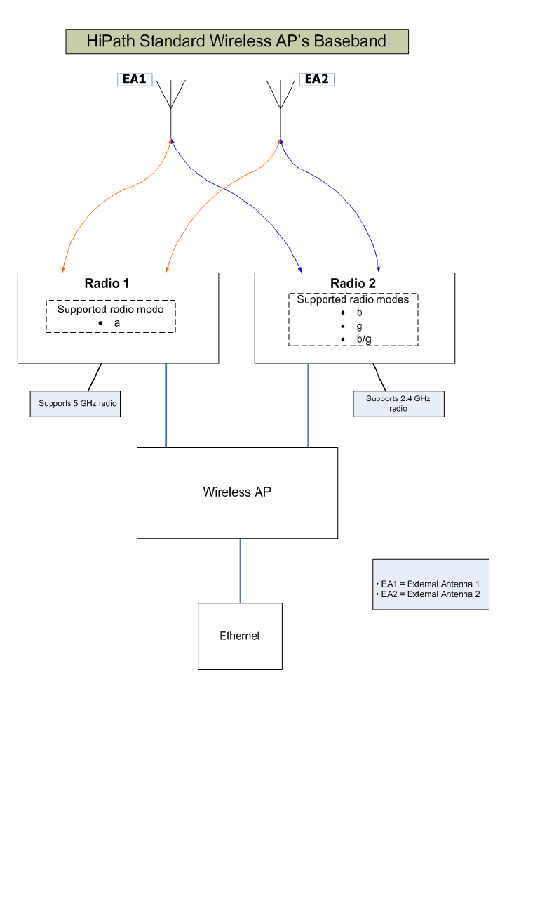
Configuring the Wireless AP
hwc_apstartup.fm
Wireless AP overview
9034530-02, March 2010
88 HiPath Wireless Controller, Access Points and Convergence Software V7.11, User Guide
Figure 5 HiPath Standard Wireless AP’s Baseband
Figure 5 illustrates the following:
•The HiPath Standard Wireless AP has two radios — Radio 1 and Radio 2.
• Radio 1 supports the 5 GHz radio, with radio mode a.
• Radio 2 supports the 2.4 GHz radio, with radio modes b, g, and b/g.
• Radio 1 and Radio 2 are connected to both external antennas — EA1 and
EA2.

hwc_apstartup.fm
Configuring the Wireless AP
Wireless AP overview
9034530-02, March 2010
HiPath Wireless Controller, Access Points and Convergence Software V7.11, User Guide 89
5 GHz radio supporting the 802.11a standard – The 802.11a standard is an
extension to 802.11 that applies to wireless LANs and provides up to 54 Mbps in
the 5-GHz band. The 802.11a standard uses an orthogonal frequency division
multiplexing encoding scheme, rather than Frequency-Hopping Spread
Spectrum (FHSS) or Direct-Sequence Spread Spectrum (DSSS).
2.4 GHz radio supporting the 802.11b/g standards – The 802.11g standard
applies to wireless LANs and specifies a transmission rate of 54 Mbps. The
802.11b (High Rate) standard is an extension to 802.11 that specifies a
transmission rate of 11 Mbps. Since 802.11g uses the same communication
frequency range as 802.11b (2.4 GHz), 802.11g devices can co-exist with
802.11b devices on the same network.
The radios are enabled or disabled through the HiPath Wireless Assistant. Both
radios can be enabled to offer service simultaneously. For more information, see
Section 4.4.5.3, “Modifying Wireless AP 2610/2620 radio properties”, on page
152.
The Unlicensed National Information Infrastructure (U-NII) bands are three
frequency bands of 100 MHz each in the 5 GHz band, designated for short-range,
high-speed, wireless networking communication.
The Wireless AP supports the full range of 802.11a:
•5.15 to 5.25 GHz – U-NII Low Band
•5.25 to 5.35 GHz – U-NII Middle Band
•5.47 to 5.725 GHz – UNII 2+
•5.725 to 5.825 GHz – U-NII High Band
4.1.1.2 AP4102/4102C Access Points
The AP4102 and AP4102C access points are Enterasys manufactured access
points that run HiPath WLAN software. The AP4102/4102C access point has 2
integrated dual-band antennas. Diversity, which is the use of two antennas to
increase the odds that a better radio stream is received on either of the antennas,
is supported only with integrated antennas.
The available external antennas for the AP4102/4102C access point are:
• Left antenna:
•RBT4K - AG - IA, 2 dBi
•RBTES - BG - M08M, 8dBi
•RBTES - BG - P18M, 18 dBi
•RBTES - BG - S1490M, 14 dBi

Configuring the Wireless AP
hwc_apstartup.fm
Wireless AP overview
9034530-02, March 2010
90 HiPath Wireless Controller, Access Points and Convergence Software V7.11, User Guide
• Right antenna:
•RBT4K - AG - IA, 4 dBi
•RBTES - AH - M10M, 110 dBi
•RBTES - AH - P23M, 23 dBi
•RBTES - AM - M10M, 10 dBi
•RBTES - AW - S1590M, 15 dBi 90 Deg
•RBTES - AW - S1590M, 16 dBi 60 Deg
The antenna selection automatically restricts channels and respective power
settings according to certifications.
4.1.2 HiPath Wireless Outdoor AP
The HiPath Wireless Outdoor AP is also referred to as the Outdoor AP. The
HiPath Wireless Outdoor AP enables you to extend your Wireless LAN beyond
the confines of indoor locations. The HiPath Wireless Outdoor AP is resistant to
harsh outdoor conditions and extreme temperatures. Using the advanced
wireless distribution feature of the HiPath Wireless LAN, the HiPath Wireless
Outdoor AP can extend your Wireless LAN to outdoor locations without Ethernet
cabling. A mounting bracket is available to enable quick and easy mounting of the
HiPath Wireless Outdoor APs to walls, rails, and poles.
The HiPath Wireless Outdoor AP supports 802.11a, 802.11g, and full backward
compatibility with legacy 802.11b devices.
The HiPath Wireless Outdoor AP is available in two models:
•AP2650 – Internal antenna, internal dual (multimode) diversity antennas
•AP2660 – External antenna (dual external antennas), RP-SMA connectors
Note: Any Outdoor AP model number in the Hardware Version box on the AP
Properties tab that ends with -1 is an Outdoor AP that contains the new Siemens
radio card. For example, the HiPath Wireless AP2650-1 Internal.
4.1.3 HiPath Wireless 802.11n AP
The HiPath Wireless 802.11n AP delivers total data rates of up to 300 Mbps,
depending on its configuration. The improved throughput of 300 Mbps is spread
over a number of simultaneous users so that the Wireless 802.11n AP provides
mobile users with an experience similar to that of a wired 100 Mbps Ethernet
connection — the standard for desktop connectivity.

hwc_apstartup.fm
Configuring the Wireless AP
Wireless AP overview
9034530-02, March 2010
HiPath Wireless Controller, Access Points and Convergence Software V7.11, User Guide 91
To configure the HiPath Wireless 802.11n AP to achieve this high link rate, see
Section 4.4.5.2, “Achieving high throughput with the Wireless 802.11n AP”, on
page 150.
Note: The Wireless 802.11n AP is backward-compatible with existing
802.11a/b/g networks.
Note: The Wireless 802.11n AP cannot operate as a stand-alone access point.
MIMO
The mainstay of 802.11 AP is MIMO (multiple input, multiple output) — a
technology that uses advanced signal processing with multiple antennas to
improve the throughput. MIMO takes advantage of multipath propagation to
decrease packet retries to improve the fidelity of the wireless network.
The 802.11n AP’s MIMO radio sends out one or two radio signals through its three
antennas. Each of these signals is called a spatial stream. Because the location
of the antennas on the 802.11n AP is spaced out, each spatial stream follows a
slightly different path to the client device. Furthermore, the three spatial streams
get multiplied into several streams as they bounce off the obstructions in the
vicinity. This phenomenon is called multipath. Since these streams are bounced
from different surfaces, they follow different paths to the client device. The client
device, which is also 802.11n compliant, also has multiple antennas. Each of the
antennas independently decodes the arriving signal. Then each antenna’s
decoded signal is combined with the decoded signals from the other antennas.
The software algorithm uses the redundancy to extract one or two spatial streams
and enhances the streams’ ‘signal to noise ratio’.
The client device too sends out one or two spatial streams through its multiple
antennas. These spatial streams get multiplied into several steams as they
bounce off the obstructions in the vicinity en route to the 802.11n AP. The 802.11n
AP's MIMO receiver receives these multiple streams with three antennas. Each
of the three antennas independently decodes the arriving signal. Then each
antennas's decoded signal is combined with the decoded signals from the other
antennas. The 802.11n AP's MIMO receiver again uses the redundancy to extract
one or two spatial streams and enhances the streams' ‘signal to noise ratio.’
By using the multiple streams, MIMO doubles the throughput.
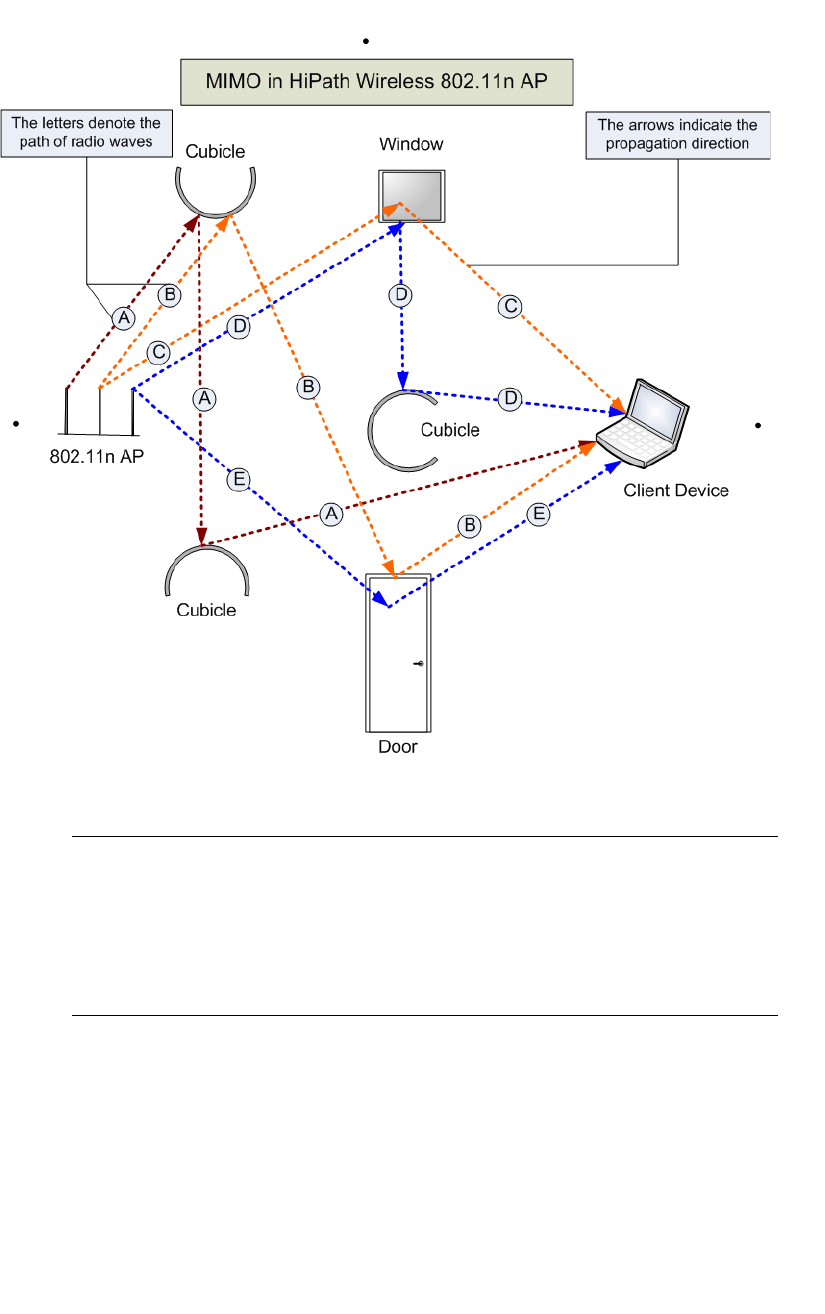
Configuring the Wireless AP
hwc_apstartup.fm
Wireless AP overview
9034530-02, March 2010
92 HiPath Wireless Controller, Access Points and Convergence Software V7.11, User Guide
Figure 6 MIMO in HiPath Wireless 802.11n AP
Note: MIMO should not be confused with the Diversity feature. While Diversity
is the use of two antennas to increase the odds that a better radio stream is
received on either of the antennas, MIMO antennas radiate and receive multi-
streams of the same packet to achieve the increased throughput.
The Diversity feature is meant to offset the liability of RF corruption, arising out
of multipath, whereas MIMO converts the liability of multipath to its advantage.
Because the 802.11n AP operates with multiple antennas, it is capable of picking
up even the weakest signals from the client devices.
Channel bonding
In addition to MIMO technology, the 802.11n AP makes a number of additional
changes to the radio to increase the effective throughput of the Wireless LAN.
The radios of regular HiPath Wireless APs use radio channels that are 20 MHz
wide. This means that the channels must be spaced at 20 MHz to avoid

hwc_apstartup.fm
Configuring the Wireless AP
Wireless AP overview
9034530-02, March 2010
HiPath Wireless Controller, Access Points and Convergence Software V7.11, User Guide 93
interference. The radios of 802.11n AP can use two channels at the same time to
create a 40 MHz wide channel. By using the two 20 MHz channels in this manner,
the 802.11n AP achieves more than double throughput. The 40-MHz channels in
802.11n are two adjacent 20-MHz channels, bonded together. This technique of
using two channels at the same time is called channel bonding.
Shortened guard interval
The purpose of the guard interval is to introduce immunity to propagation delays,
echoes and reflections of symbols in orthogonal frequency division multiplexing
(OFDM) — a method by which information is transmitted via a radio signal in
Wireless APs.
In OFDM, the beginning of each symbol is preceded by a guard interval. As long
as the echoes fall within this interval, they will not affect the safe decoding of the
actual data, as data are only interpreted outside the guard interval. Longer guard
periods reduce the channel efficiency. The 802.11n AP provides reduced guard
periods, thereby increasing the throughput.
MAC enhancements
The 802.11n AP also has an improved MAC layer protocol that reduces overhead
(in the MAC layer protocol) and contention losses. This results in increased
throughput.
Models
The Wireless 802.11n AP is available in the following two models:
• Model AP3610 – Six internal antennas
• Model AP3620 – Three external antennas
Note: Any Wireless 802.11n AP model number in the Hardware Version box on
the Properties tab that ends with -1 is a Wireless 802.11n AP that has its DFS
channels disabled. For more information, see Appendix B.
Environment
The Wireless 802.11n AP cannot be deployed in an outdoor environment.
4.1.3.1 HiPath Wireless 802.11n AP’s radios
The HiPath Wireless 802.11n AP is equipped with two radios — Radio 1 and
Radio 2. The following is a block diagram of the HiPath Wireless 802.11n AP
equipped with external antennas.
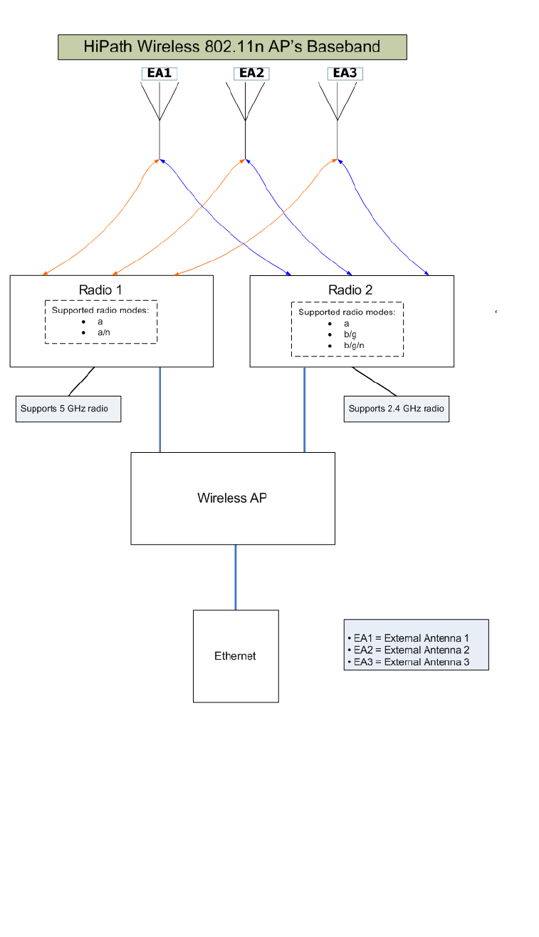
Configuring the Wireless AP
hwc_apstartup.fm
Wireless AP overview
9034530-02, March 2010
94 HiPath Wireless Controller, Access Points and Convergence Software V7.11, User Guide
Figure 7 HiPath Wireless 802.11n AP’s Baseband
Figure 7 illustrates the following:
•The HiPath Wireless 802.11n AP has two radios — Radio 1 and Radio 2.
• Radio 1 supports the 5 GHz radio, with radio modes a and a/n.
• Radio 2 supports the 2.4 GHz radio, with radio modes b, b/g, and b/g/n.
•Radio 1 and Radio 2 are connected to all three antennas — EA1, EA2, and
EA3.

hwc_apstartup.fm
Configuring the Wireless AP
Wireless AP overview
9034530-02, March 2010
HiPath Wireless Controller, Access Points and Convergence Software V7.11, User Guide 95
5 GHz radio supporting the 802.11a/n standard — When in legacy 802.11a
mode, the AP36xx supports data rates up to 54Mbps, identical to the AP26xx.
The modulation used is OFDM. In 802.11n mode there are 2 supported channel
bandwidths, 20MHz and 40MHz. The 802.11n AP supports up to 300Mbps in
40MHz channels and 130Mbps in 20MHz channels. The modulation used is
MIMO-OFDM with one or two spatial streams.
2.4 GHz radio supporting the 802.11b/g/n standard — When in legacy
802.11b/g mode, the AP36xx supports data rates up to 54Mbps, identical to the
AP26xx. The modulation used is OFDM for 11g and CCK for 11b. In 802.11n
mode there are 2 supported channel bandwidths, 20MHz and 40MHz. The
AP36xx supports up to 300Mbps in 40MHz channels and 130Mbps in 20MHz
channels. The modulation used is MIMO-OFDM with one or two spatial streams.
The radios are enabled or disabled through the HiPath Wireless Assistant. For
more information, see Section 4.4.5.1, “Modifying Wireless 802.11n AP
3610/3620 radio properties”, on page 133.
The Unlicensed National Information Infrastructure (U-NII) bands are three
frequency bands of 100 MHz each in the 5 GHz band, designated for short-range,
high-speed, wireless networking communication.
The 802.11n AP supports the full range of frequencies available in the 5GHz
band:
•5150 to 5250 MHz - U-NII Low band
•5250 to 5350 MHz - U-NII middle band
•5470 to 5700 MHz - U-NII Worldwide
•5725 to 5825 MHz - U-NII high band
Note: The Wireless 802.11n AP can achieve link rates of up to 300Mbps. To
achieve this level of high link rates, specific items need to be configured through
the HiPath Wireless Assistant. For more information, see Section 4.4.5.2,
“Achieving high throughput with the Wireless 802.11n AP”, on page 150.
4.1.4 Wireless AP international licensing
The Wireless AP must be configured to operate on the appropriate radio band in
accordance with the regulations of the country in which it is being used. For more
information, see Appendix B.
To configure the appropriate radio band according to the country of operation,
use the HiPath Wireless Assistant. For more information, see Section 4.4,
“Configuring Wireless AP settings”, on page 119.

Configuring the Wireless AP
hwc_apstartup.fm
Wireless AP overview
9034530-02, March 2010
96 HiPath Wireless Controller, Access Points and Convergence Software V7.11, User Guide
4.1.5 Wireless AP default IP address and first-time
configuration
The Wireless APs are shipped from the factory with a default IP address —
192.168.1.20. The default IP address simplifies the first-time IP address
configuration process for Wireless APs. If the Wireless AP fails in its discovery
process, it returns to its default IP address. This Wireless AP behavior ensures
that only one Wireless AP at a time can use the default IP address on a subnet.
For more information, see Section 4.2, “Discovery and registration overview”, on
page 97.
The Wireless APs can acquire their IP addresses by either of the following two
methods:
• DHCP assignment – When the Wireless AP is powered on, it attempts to
reach the DHCP server on the network to acquire the IP address. If the
Wireless AP is successful in reaching the DHCP server, the DHCP server
assigns an IP address to the Wireless AP.
•If the DHCP assignment is not successful in the first 60 seconds, the
Wireless AP returns to its default IP address.
•The Wireless AP waits for 30 seconds in default IP address mode before
again attempting to acquire an IP address from the DHCP server.
•The process repeats itself until the DHCP assignment is successful, or
until an administrator assigns the Wireless AP an IP address, using static
configuration.
Note: DCHP assignment is the default method for the Wireless AP
configuration. DHCP assignment is part of the discovery process. For more
information, see Section 4.2, “Discovery and registration overview”, on page
97.
• Static configuration – You can assign a static IP address to the Wireless AP,
using the static configuration option. For more information, see the following
section.
Note: You can establish a telnet or SSH session with the Wireless AP during
the time window of 30 seconds when the Wireless AP returns to its default IP
address mode. If a static IP address is assigned during this period, you must
reboot the Wireless AP for the configuration to take effect. For more
information, see Section 4.1.6, “Assigning a static IP address to the Wireless
AP”, on page 97.

hwc_apstartup.fm
Configuring the Wireless AP
Discovery and registration overview
9034530-02, March 2010
HiPath Wireless Controller, Access Points and Convergence Software V7.11, User Guide 97
4.1.6 Assigning a static IP address to the Wireless AP
Depending upon the network condition, you can assign a static IP address to the
Wireless AP using the HiPath Wireless Assistant (Controller’s GUI). Refer to
Section 4.4.6, “Setting up the Wireless AP using static configuration”, on page
165 for more information.
4.2 Discovery and registration overview
When the Wireless AP is powered on, it automatically begins a discovery process
to determine its own IP address and the IP address of the HiPath Wireless
Controller. When the discovery process is successful, the Wireless AP registers
with the HiPath Wireless Controller.
Warning: Only use power supplies that are recommended by Siemens. For
example, for the Wireless 802.11n AP use Siemens S30122-X8010-X13.
4.2.1 Wireless AP discovery
Wireless APs discover the IP address of a HiPath Wireless Controller using a
sequence of mechanisms that allow for the possible services available on the
enterprise network. The discovery process is successful when the Wireless AP
successfully locates a HiPath Wireless Controller to which it can register.
You must ensure that the appropriate services on your enterprise network are
prepared to support the discovery process. The following five steps summarize
the discovery process:
• Step 1 – Use the IP address of the last successful connection to a HiPath
Wireless Controller.
Once a Wireless AP has successfully registered with a HiPath Wireless
Controller, it recalls that controller's IP address, and uses that address on
subsequent reboots. The Wireless AP bypasses discovery and goes straight
to registration.
If this discovery method fails, it cycles through the remaining steps until
successful.
• Step 2 – Use the predefined static IP addresses for the HiPath Wireless
Controllers on the network (if configured).

Configuring the Wireless AP
hwc_apstartup.fm
Discovery and registration overview
9034530-02, March 2010
98 HiPath Wireless Controller, Access Points and Convergence Software V7.11, User Guide
You can specify a list of static IP addresses of the HiPath Wireless Controllers
on your network. On the Static Configuration tab, add the addresses to the
Wireless Controller Search List.
Caution: Wireless APs configured with a static Wireless Controller Search
List can only connect to HiPath Wireless Controllers in the list. Improperly
configured Wireless APs cannot connect to a non-existent HiPath Wireless
Controller address, and therefore cannot receive a corrected configuration.
• Step 3 – Use Dynamic Host Configuration Protocol (DHCP) Option 78 to
locate a Service Location Protocol (SLP) Directory Agent (DA), followed
by a unicast SLP request to the Directory Agent.
To use the DHCP and unicast SLP discovery method, you must ensure that
the DHCP server on your network supports Option 78 (DHCP for SLP
RFC2610). The Wireless APs use this method to discover the HiPath
Wireless Controller.
This solution takes advantage of two services that are present on most
networks:
• DHCP (Dynamic Host Configuration Protocol) – The standard is a
means of providing IP addresses dynamically to devices on a network.
• SLP (Service Location Protocol) – A means of allowing client
applications to discover network services without knowing their location
beforehand. Devices advertise their services using a Service Agent (SA).
In larger installations, a Directory Agent (DA) collects information from
SAs and creates a central repository (SLP RFC2608).
The HiPath Wireless Controller contains an SLP SA that, when started,
queries the DHCP server for Option 78 and if found, registers itself with the
DA as service type Siemens. The HiPath Wireless Controller contains a DA
(SLPD).
The Wireless AP queries DHCP servers for Option 78 in order to locate any
DAs. The Wireless APs SLP User Agent then queries the DAs for a list of
Siemens SAs.
Option 78 must be set for the subnets connected to the ports of the HiPath
Wireless Controller and the subnets connected to the Wireless APs. These
subnets must contain an identical list of DA IP addresses.
• Step 4 – Use a Domain Name Server (DNS) lookup for the host name
Controller.domain-name.
If no DA is found, or if it has no Siemens SAs registered, the Wireless AP
attempts to locate a HiPath Wireless Controller via DNS.
If you use this method for discovery, place an A record in the DNS server for
Controller.<domain-name>. The <domain-name> is optional, but if used,
ensure it is listed with the DHCP server.

hwc_apstartup.fm
Configuring the Wireless AP
Discovery and registration overview
9034530-02, March 2010
HiPath Wireless Controller, Access Points and Convergence Software V7.11, User Guide 99
• Step 5 – Use a multicast SLP request to find SLP SAs
If all of the preceding methods fail to locate a HiPath Wireless Controller, the
Wireless AP sends a multicast SLP request, looking for any SLP Service
Agents providing the Siemens service.
4.2.2 Registration after discovery
Any of the discovery steps 2 through 5 can inform the Wireless AP of a list of
multiple IP addresses to which the Wireless AP may attempt to connect. Once the
Wireless AP has discovered these addresses, it sends out connection requests
to each of them. These requests are sent simultaneously. The Wireless AP will
attempt to register only with the first which responds to its request.
When the Wireless AP obtains the IP address of the HiPath Wireless Controller,
it connects and registers, sending its serial number identifier to the HiPath
Wireless Controller, and receiving from the HiPath Wireless Controller a port IP
address and binding key.
Once the Wireless AP is registered with a HiPath Wireless Controller, the
Wireless AP must be configured. After the Wireless AP is registered and
configured, it can be assigned to a Virtual Network Segment (VNS) to handle
wireless traffic.
4.2.2.1 Default Wireless AP configuration
Default Wireless AP configuration simplifies the registration after discovery
process. Default Wireless AP configuration acts as a configuration template that
can be automatically assigned to new registering Wireless APs. The default
Wireless AP configuration allows you to specify common sets of radio
configuration parameters and VNS assignments for Wireless APs. For more
information, see Section 4.5.3, “Configuring the default Wireless AP settings”, on
page 181.
4.2.3 Understanding the Wireless AP LED status
When you power on and boot the Wireless AP, you can follow its progress
through the registration process by observing the LED sequence as described in
the following sections:
•Section 4.2.3.1, “HiPath Wireless AP LED status”
•Section 4.2.3.2, “HiPath Wireless Outdoor AP LED status”
•Section 4.2.3.2, “HiPath Wireless Outdoor AP LED status”
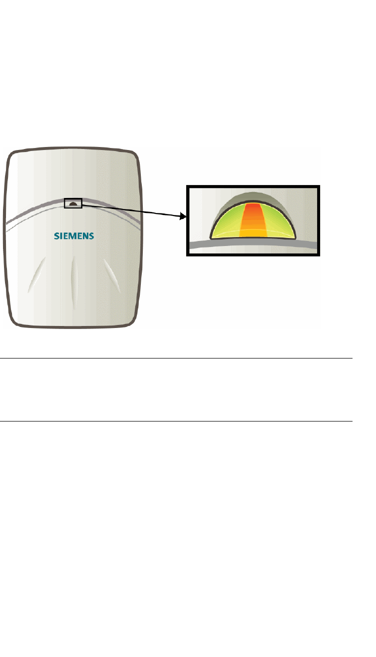
Configuring the Wireless AP
hwc_apstartup.fm
Discovery and registration overview
9034530-02, March 2010
100 HiPath Wireless Controller, Access Points and Convergence Software V7.11, User Guide
After the first time you power on and boot the Wireless AP, you can configure LED
behavior as described in the following section:
•Section 4.2.3.5, “Configuring Wireless AP LED Behavior”
4.2.3.1 HiPath Wireless AP LED status
The following figure depicts the location of the three LEDs on the HiPath Wireless
AP.
Figure 8 HiPath Wireless AP LEDs
Warning: Never disconnect a Wireless AP from its power supply during a
firmware upgrade.
Disconnecting a Wireless AP from its power supply during a firmware upgrade
may cause firmware corruption rendering the AP unusable.
LED color codes
The AP LEDs indicate “normal-operation”, “warning/special”, or “failed” state of
the Wireless AP in the following color codes:
•Green – Indicates the normal-operation state.
•Orange/Amber – Indicates the warning, or special state such as WDS.
•Red – Indicates the error state.
•Blinking – Indicates that the state, such as initialization, or discovery is in
progress.
•Steady – Indicates that the state is stable/completed. For example,
initialization finished, or discovery completed.
Left LED
2.4 GHz
radio activity
Right LED
5 GHz radio
activity
Status
LED

hwc_apstartup.fm
Configuring the Wireless AP
Discovery and registration overview
9034530-02, March 2010
HiPath Wireless Controller, Access Points and Convergence Software V7.11, User Guide 101
Center LED
The Center LED indicates the general status of the Wireless AP:
Left LED
The Left LED indicates the high-level state of the Wireless AP during the
initialization and discovery process:
Left and Right LEDs
The Right LED indicates the detailed state during the initialization and discovery
processes:
Center LED HiPath Wireless AP’s status
Blinking Green Initialization and discovery in progress via Ethernet link
Blinking Orange/Amber Initialization and discovery in progress via WDS link
Blinking Red Error during initialization/discovery process
Solid Red Irrecoverable error
Solid Green Discovery finished via Ethernet link
Solid Orange/Amber Discovery finished via WDS link
Table 3 Center LED and Wireless AP’s status
Left LED HiPath Wireless AP’s high-level state
Off Initialization
Blinking Green Network Discovery
Solid Green Connecting with the HiPath Wireless Controller
Table 4 Left LED and Wireless AP’s high-level state
Left LED Right LED HiPath Wireless AP’s detailed state
Off
Off Initialization: Power-on self-test (POST)
Blinking Green Initialization: Random delay
Solid Green Initialization: Vulnerable period
Blinking Green
Off Network Discovery: 802.1X authentication
Blinking Green Network Discovery: Attempting to obtain IP
address via DHCP
Solid Green Network Discovery: Discovered HiPath
Wireless Controller
Solid Green
Off Connecting to HiPath Wireless Controller:
Attempting to register with the HiPath Wireless
Controller
Blinking Green Connecting to HiPath Wireless Controller:
Upgrading to higher version
Solid Green Connecting to HiPath Wireless Controller:
Configuring itself
Table 5 Left and Right LEDs and Wireless AP’s detailed state

Configuring the Wireless AP
hwc_apstartup.fm
Discovery and registration overview
9034530-02, March 2010
102 HiPath Wireless Controller, Access Points and Convergence Software V7.11, User Guide
Composite view of the three LEDs
The Center, Left and the Right LEDs work in conjunction to indicate the general,
high-level state and the detailed state respectively.
Table 6 provides a composite view of the three LED lights of the Wireless AP’s
state:
Left LED Right LED Center LED HiPath Wireless AP’s Detailed state
Off
Off Blinking
Green
Initialization: Power-on self-test (POST)
Blinking
Green
Blinking
Green
Initialization: Random delay
Blinking Red Initialization: Neither Ethernet nor WDS
link
Solid Green
Blinking
Green
Initialization: Vulnerable period
Blinking Red Reset to factory defaults
Blinking
Orange
WDS scanning
Blinking
Green
Off
Blinking
Green /
Orange
Network discovery: 802.1x authentication
Blinking Red Failed 802.1x authentication
Blinking
Green
Blinking
Green /
Orange
Network discovery: DHCP
Blinking Red Default IP address
Solid Green
Blinking
Green /
Orange
Network discovery: HWC discovery /
connect
Blinking Red Discovery failed
Solid Green
Off
Blinking
Green /
Orange
Connecting with HiPath Wireless
Controller: Registration
Blinking Red Registration failed
Blinking
Green
Blinking
Green /
Orange
Connecting with HiPath Wireless
Controller: Image upgrade
Solid Green /
Orange
AP operating normally: Forced image
upgrade
Blinking Red Image upgrade failed
Solid Green
Blinking
Green /
Orange
Connecting with HiPath Wireless
Controller: Configuration
Blinking Red Configuration failed
Table 6 Composite view of three LED lights
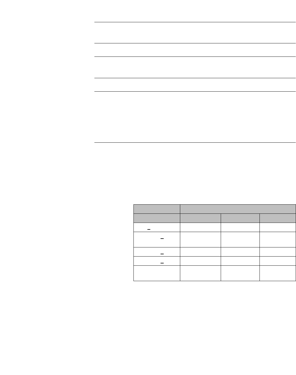
hwc_apstartup.fm
Configuring the Wireless AP
Discovery and registration overview
9034530-02, March 2010
HiPath Wireless Controller, Access Points and Convergence Software V7.11, User Guide 103
Note: The Left and Right LEDs turn on after the Center LED. This allows you to
distinguish easily between the Center LED and the Left/Right LEDs.
Note: If the Center LED begins blinking RED, it indicates that the Wireless AP’s
state has failed.
Note: Random delays do not occur during normal reboot. A random delay only
occurs after a vulnerable period power-down.
The Wireless AP can be reset to its factory default settings. For more information,
see the HiPath Wireless Controller, Access Points and Convergence Software
Maintenance Guide.
LEDS indicating WDS strength for AP2610 and AP2620
The AP indicates the WDS signal strength as a bar graph. To avoid confusion
with startup LED behavior, the patterns go from right to left and an LED is always
blinking at least twice as fast as the LEDs in normal mode.
Table 7 illustrates the behavior of the three LED lights of the Wireless AP’s WDS
strength.
4.2.3.2 HiPath Wireless Outdoor AP LED status
The following figure depicts the location of the LEDs on the HiPath Wireless
Outdoor AP.
LED
RSS (dBm) Left LED Middle LED Right LED
RSS < -84 Off Off Blinking green
-84 < RSS < -77 Off Off FastBlinking
green
-77 < RSS < -70 Off Blinking green Solid green
-70 < RSS < -63 Blinking green Solid green Solid green
RSS < -63 Fast Blinking
green
Solid green Solid green
Table 7 AP2610 and AP2620 LEDs indicating Signal Strength
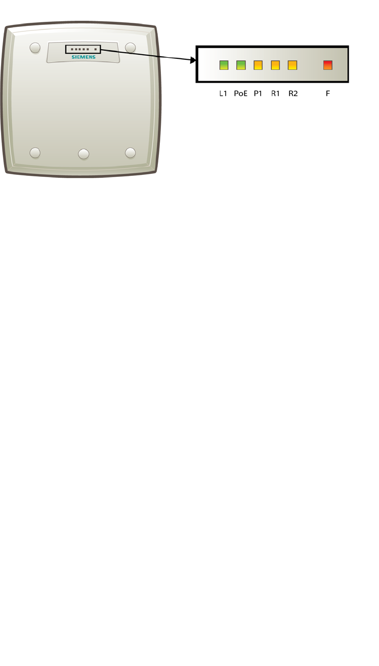
Configuring the Wireless AP
hwc_apstartup.fm
Discovery and registration overview
9034530-02, March 2010
104 HiPath Wireless Controller, Access Points and Convergence Software V7.11, User Guide
Figure 9 HiPath Wireless Outdoor AP LEDs.
The R1, R2 and F LEDs work in conjunction to indicate the general, high-level
and detailed state respectively. The remaining LEDs indicate link status.
Table 8 provides a composite view of the R1, R2 and F LEDs:

hwc_apstartup.fm
Configuring the Wireless AP
Discovery and registration overview
9034530-02, March 2010
HiPath Wireless Controller, Access Points and Convergence Software V7.11, User Guide 105
Note: After discovery is finished, the Left and Right LEDs will be Green for
Ethernet uplink, and Yellow for WDS uplink.
Note: If a fatal AP error occurs, the Status LED will be solid Red.
LEDS indicating WDS strength for AP2650 and AP2660
The AP indicates the WDS signal strength as a bar graph. To avoid confusion
with startup LED behavior, the patterns go from right to left and an LED is always
blinking at least twice as fast as the LEDs in normal mode.
Table 9 illustrates the behavior of the LED in WDS Signal Strength for AP models
AP2650 and AP2660.
R1 LED R2 LED F LED HiPath Wireless Outdoor AP’s
detailed status
Off
Off Blinking Red Initialization: Power-on-self test (POST)
Blinking
Green
Blinking Red Initialization: Random delay
Solid Green
Blinking Red Initialization: Vulnerable Period
Solid Red Reset to factory defaults
Solid Green Blinking Red WDS scanning
Blinking
Green/Ye
llow
Off
Blinking Red Network discovery: 802.1x
authentication
Solid Red Failed 802.1x authentication
Blinking
Green/Yellow
Blinking Red Network discovery: DHCP
Solid Red Default IP address
Solid
Green/Yellow
Blinking Red Network discovery: HWC
discovery/connect
Solid Red Discovery failed
Solid
Green
Off
Blinking Red Connecting with HWC: Registration
Solid Red Registration failed
Blinking
Green/Yellow
Blinking Red Connecting with HWC: Image upgrade
Solid Red Image upgrade failed
Solid
Green/Yellow
Blinking Red Connecting with HWC: Configuration
Solid Red Configuration failed
Blinking
Green/Yellow
Off AP operating and running normally:
Forced image upgrade
Solid Red Image upgrade failed
Table 8 HiPath Wireless Outdoor AP LED status

Configuring the Wireless AP
hwc_apstartup.fm
Discovery and registration overview
9034530-02, March 2010
106 HiPath Wireless Controller, Access Points and Convergence Software V7.11, User Guide
LED
RSS (dBm) L1 PoE P1 R1 R2 F
RSS < -84 Off Off Off Off Off Blinking green
-84 < RSS < -77 Off Off Off Off Off Fast Blinking
green
-77 < RSS < -70 Off Off Off Off Blinking green Solid green
-70 < RSS < -63 Off Off Off Blinking green Solid green Solid green
-63 < RSS < -56 Off Off Blinking green Solid green Solid green Solid green
-56 < RSS < -49 Off Blinking
green
Solid green Solid green Solid green Solid green
-49 < RSS < -42 Blinking green Solid green Solid green Solid green Solid green Solid green
RSS < -42 Fast Blinking
green
Solid green Solid green Solid green Solid green Solid green
Table 9 AP2650 and AP2660 LEDs indicating Signal Strength
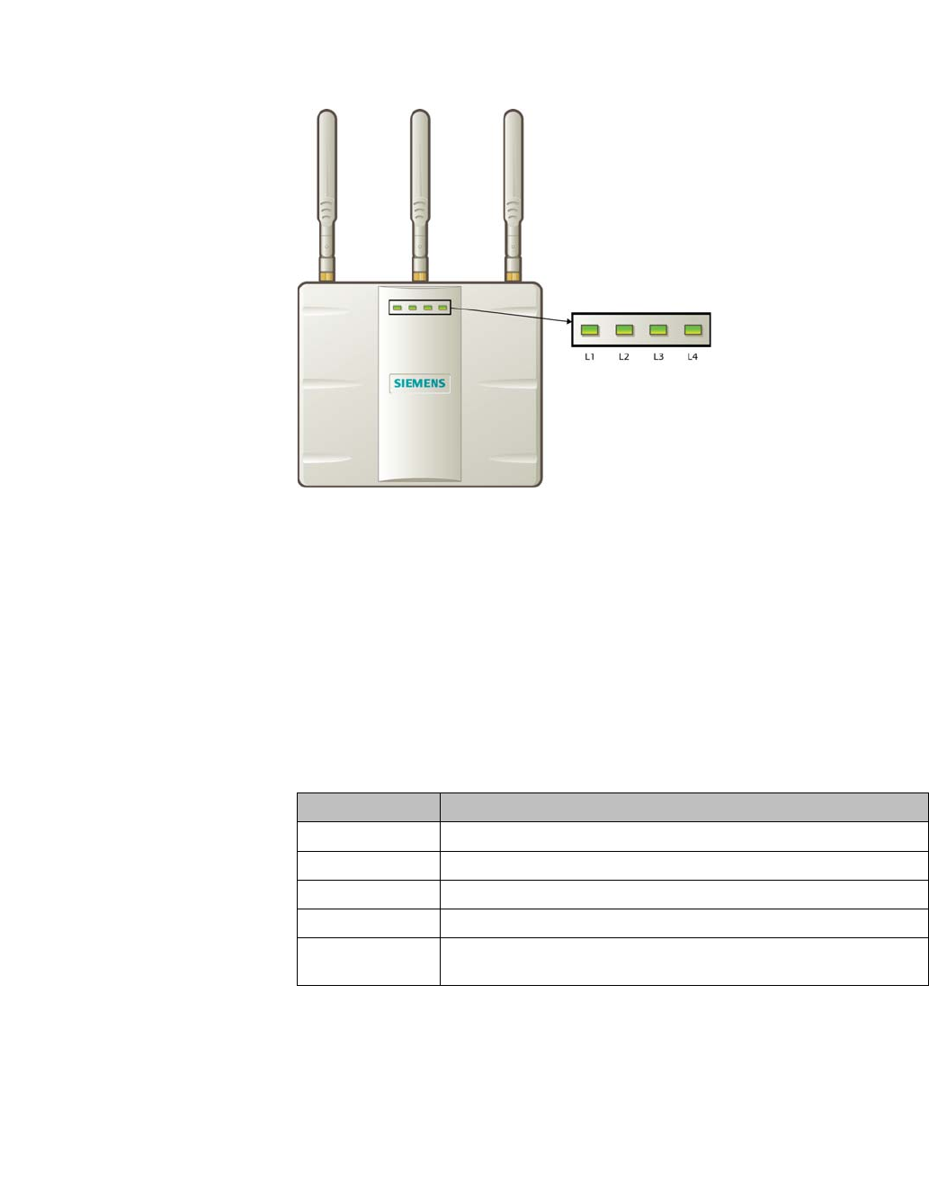
hwc_apstartup.fm
Configuring the Wireless AP
Discovery and registration overview
9034530-02, March 2010
HiPath Wireless Controller, Access Points and Convergence Software V7.11, User Guide 107
4.2.3.3 HiPath Wireless 802.11n AP LED status
Figure 10 depicts the location of the LEDs on the HiPath Wireless 802.11n.
Figure 10 HiPath Wireless 802.11n AP LEDs
LEDs L1, L3, and L4 work in conjunction to indicate the general, high-level, and
detailed state respectively. LED L2 indicates the status of the Ethernet port.
After initialization and discovery is completed and the 802.11n AP is connected
to the HiPath Wireless Controller, LEDs L3 and L4 indicate the state of the
corresponding radio — L3 for Radio 5 GHz, and L4 for Radio 2.4 GHz.
LEDs color codes
The 802.11n AP LEDs indicate “normal-operation”, “warning/special”, or “failed”
state of the Wireless AP in the following color codes:
Table 10 LED color codes
LED L1
LED L1 indicates the general state of the 802.11n AP:
LED Color/State Description
Green Normal operational state.
Orange/amber Warning or special state, such as WDS.
Blinking AP state, such as initialization or discovery, is in progress.
Red Error state
Steady color AP state is stable;process is completed. For example, initialization
is finished or discovery completed.

Configuring the Wireless AP
hwc_apstartup.fm
Discovery and registration overview
9034530-02, March 2010
108 HiPath Wireless Controller, Access Points and Convergence Software V7.11, User Guide
LEDs L3 and L4
LEDs L3 and L4 indicate the detailed state of the Wireless AP. LEDs L1, L3, and
L4 work in conjunction to indicate the general and detailed state of the 802.11n
AP.
Table 12 provides a composite view of the three LEDs and the corresponding
state of the 802.11n AP:
L1 HiPath Wireless 802.11n AP’s general state
Blink Green Initialization and discovery in progress via Ethernet
Blink Amber Initialization and discovery in progress via WDS
Blink Red Error during initialization and discovery
Solid Green Discovery finished via Ethernet
Solid Amber Discovery finished via WDS
Table 11 LED L1 and Wireless AP’s status
L3 L4 L1 HiPath Wireless 802.11n AP’s detailed state
Off
Off Blink Green
Initialization: Power-on self test (POST)
Blink Green Blink Green
Blink Red
Solid Green
Blink Green
Blink Red
Blink Amber
Blink
Green
Off
Blink Green
/ Orange
Network discovery: 802.1x authentication
Blink Red Failed 802.1x authentication
Blink Green Blink Green
/ Amber
Network discovery: DHCP
Blink Red Default IP address
Solid Green Blink Green
/ Amber
Network discovery: HWC discovery / connect
Blink Red Discovery failed
Table 12 LEDs L3, L4 and L1, and Wireless 802.11n AP’s detailed state

hwc_apstartup.fm
Configuring the Wireless AP
Discovery and registration overview
9034530-02, March 2010
HiPath Wireless Controller, Access Points and Convergence Software V7.11, User Guide 109
After initialization and discovery is completed and the 802.11n AP is connected
to the HiPath Wireless Controller, the LEDs L3 and L4 indicate the state of the
corresponding radio — L3 for Radio 5 GHz, and L4 for Radio 2.4 GHz.
Figure 10 provides a view of the LEDs L3 and L4 and the corresponding radio
state after the discovery is completed.
LED L2
The LED L2 indicates the status of the Ethernet port:
Note: A 10 Mb Ethernet connection is considered a warning state since it is not
sufficient to sustain a single radio in the legacy 11g or 11a modes.
Solid
Green
Off
Blink Green
/ Amber
Connecting to HWC: Registration
Blink Red Registration failed
Blink Green
Blink Green
Amber
Connecting to HWC: Image upgrade
Solid Green
/ Amber
AP operating normally: Forced image upgrade
Blink Red Image upgrade failed
Solid Green
Blink Green
/ Amber
Connecting to HWC: Configuration
Blink Red Configuration failed
L3/L4 Radio status
Off Radio off
Solid Blue Radio in HT mode
Solid Green Radio in legacy mode
Table 13 LEDs L3 and L4, and corresponding radio state
L2 Ethernet port’s status
Off No Ethernet connection: WDS is enabled
Solid Blue 1 Gb Ethernet connection
Solid Green 100 Mb Ethernet connection
Solid Amber 10 Mb Ethernet connection
Table 14 LED L2 and Ethernet port’s status
L3 L4 L1 HiPath Wireless 802.11n AP’s detailed state
Table 12 LEDs L3, L4 and L1, and Wireless 802.11n AP’s detailed state
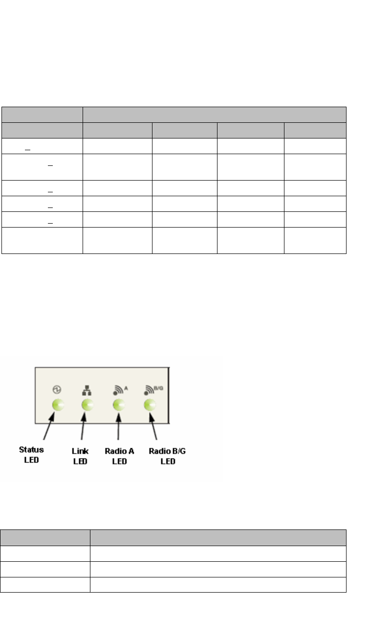
Configuring the Wireless AP
hwc_apstartup.fm
Discovery and registration overview
9034530-02, March 2010
110 HiPath Wireless Controller, Access Points and Convergence Software V7.11, User Guide
LEDS indicating WDS strength for AP3610, AP3620, AP3630, and AP3640
The AP indicates the WDS signal strength as a bar graph. To avoid confusion
with startup LED behavior, the patterns go from right to left and an LED is always
blinking at least twice as fast as the LEDs in normal mode.
Table 15 illustrates the behavior of the LED behavior in WDS Signal Strength
mode for AP models AP3610, AP3620, AP3630, and AP3640.
4.2.3.4 AP4102 and AP2605 LED status
The following figure shows the LEDs on the AP4102 and AP2605 Access Points.
Status LED
The Status LED indicates the general status of the access point.
LED
RSS (dBm) L1 L2 L3 L4
RSS < -84 Off Off Off Blinking green
-84 < RSS < -77 Off Off Off Fast Blinking
green
-77 < RSS < -70 Off Off Blinking green Solid green
-70 < RSS < -63 Off Blinking green Solid green Solid green
-63 < RSS < -56 Blinking green Solid green Solid green Solid green
RSS < -56 Fast Blinking
green
Solid green Solid green Solid green
Table 15 AP3610, AP3620, AP3630, and AP3640 LEDs indicating Signal
Strength
Status LED AP Status
Blink green Initialization and discovery in progress via Ethernet or WDS link
Blink amber Error during initialization and discovery
Solid green Discovery finished via Ethernet or WDS link
Table 16 AP4102 and AP2605 Status indicators

hwc_apstartup.fm
Configuring the Wireless AP
Discovery and registration overview
9034530-02, March 2010
HiPath Wireless Controller, Access Points and Convergence Software V7.11, User Guide 111
Radio B/G LED
The Radio B/G LED will show the general high-level state during initialization and
discovery for the access point.
Composite view of LEDs
The following table summarizes all LEDs during the initialization and discovery.
These states will be shown together with a status LED blinking green or orange.
If the status LED is blinking green, the state will be the one executed by the AP
in that moment. If the status LED is blinking orange, the state will be the one that
the AP failed.
The status and radio LEDs will blink with 1/3 pulse width, but the radio LEDs will
turn on after the status LED. This solution also allows the user to distinguish
easily between the status LED and the radio LEDs.
Radio B/G LED AP High-Level State
Off Initialization
Blink green Network discovery
Solid green Connecting with HiPath Wireless Controller
Table 17 AP4102 and AP2605 initialization and discovery indicators

Configuring the Wireless AP
hwc_apstartup.fm
Discovery and registration overview
9034530-02, March 2010
112 HiPath Wireless Controller, Access Points and Convergence Software V7.11, User Guide
LEDS indicating WDS strength for AP4102 and AP2605
The AP indicates the WDS signal strength as a bar graph. To avoid confusion
with startup LED behavior, the patterns go from right to left and an LED is always
blinking at least twice as fast as the LEDs in normal mode.
Table 19 illustrates the LED behavior in WDS Signal Strength mode for AP
models AP4102 and AP2605.
Radio B/G
LED Radio A
LED Status
LED AP Detailed State
Off
Off Blink green Initialization: Power-on self test
(POST)
Blink green
Blink green Initialization: Random delay
Blink orange Initialization: No Ethernet nor WDS
link
Solid green Blink green Initialization: Vulnerable period
Blink orange Reset to factory defaults
Solid green Blink green WDS scanning
Blink green
Off
Blink green Network discovery: 802.1x
authentication
Blink orange Failed 802.1x authentication
Blink green Blink green Network discovery: DHCP
Blink orange Default IP address
Solid green
Blink green Network discovery: HWC discovery /
connect
Blink orange Discovery failed
Solid Green
Off Blink green Connecting with HWC: Registration
Blink orange Registration failed
Blink green
Blink green Connecting with HWC: Image
upgrade
Blink orange Image upgrade failed
Solid green Blink green Connecting with HWC: Configuration
Blink orange Configuration failed
Blink green
Solid green AP up and running: Forced image
upgrade
Blink orange Image upgrade failed
Table 18 AP4102 and AP2605 composite view of LEDs
LED
RSS (dBm) Status Link Radio A Radio B/G
RSS < -84 Off Eth state Off Blinking green
Table 19 AP4102 and AP2605 LEDs indicating Signal Strength

hwc_apstartup.fm
Configuring the Wireless AP
Discovery and registration overview
9034530-02, March 2010
HiPath Wireless Controller, Access Points and Convergence Software V7.11, User Guide 113
4.2.3.5 Configuring Wireless AP LED Behavior
You can configure the behavior of the LEDs so that they provide the following
information:
You can configure the AP LED mode when you configure:
•An individual Wireless AP.
•Multiple Wireless APs simultaneously.
•Default Wireless AP behavior.
To configure the AP LED operational mode when configuring an individual
Wireless AP:
1. From the main menu, click Wireless AP Configuration. The HiPath
Wireless AP screen displays.
1. In the left-hand pane, click All APs. The AP Configuration page displays
with the AP Properties tab exposed.
2. In the second column from the left, select the appropriate
-84 < RSS < -77 Off Eth state Off Fast Blinking
green
-77 < RSS < -70 Off Eth state Blinking green Solid green
-70 < RSS < -63 Blinking green Eth state Solid green Solid green
RSS < -63 Fast Blinking
green
Eth state Solid green Solid green
LED Mode Information Displayed
Off Displays fault patterns only. LEDs do not light when the
AP is fault free and the discovery is complete.
Normal Identifies the AP status during the registration process
during power on and boot process.
Identify All LEDs blink simultaneously approximately two to four
times every second.
WDS Signal Strength Indicates the WDS signal strength as a bar graph. See
Section 4.2.3.5, “Configuring Wireless AP LED Behavior”
for a description of LED behavior.
This setting helps to align external antennas in WDS
deployments by correlating the WDS link RSS with the
LED pattern. Use this setting only if the AP operates in
WDS mode by being a member of a WDS VNS.
Table 20 LED operational modes
LED
Table 19 AP4102 and AP2605 LEDs indicating Signal Strength

Configuring the Wireless AP
hwc_apstartup.fm
Discovery and registration overview
9034530-02, March 2010
114 HiPath Wireless Controller, Access Points and Convergence Software V7.11, User Guide
3. On the AP Properties tab, click the Advanced button. The Advanced
window displays.
4. In the LED field, click the arrow and select an LED operational mode. See
Table 20 for a description of each option.
To set the AP LED operational mode when using the AP mulit-edit feature:
1. From the main menu, click Wireless AP Configuration. The HiPath
Wireless AP window displays.
2. In the left-hand pane, click AP Multi-edit. The AP Multi-edit window
displays.
3. In the Wireless AP section, select one or more Wireless APs. The AP
Configuration screen displays.
4. In the AP Configuration section, locate the LED field. Click the arrow and
select an LED operational mode. See Table 20 for a description of each
option.
To set the AP LED operational mode when configuring default AP behavior:
1. From the main menu, click Wireless AP Configuration. The HiPath
Wireless AP screen is displayed.
2. In the left pane, click AP Default Settings. The AP Default Settings page
displays with the Common Configuration tab exposed.
3. Click the AP tab that corresponds to the type of AP that you want to configure.
The AP Properties and Radio settings become available.
4. Click the Advanced button. The Advanced window displays.
5. In the LED field, click the arrow and select an LED operational mode. See
Table 20 for a description of each option.
4.2.4 Configuring the Wireless APs for the first time
Before the Wireless AP is configured for the first time, you must first confirm that
the following has already occurred:
•The HiPath Wireless Controller has been set up. For more information, see
Section , “Configuring the HiPath Wireless Controller”, on page 39.
•The HiPath Wireless Controller, Access Points and Convergence Software
has been configured. For more information, see Section , “Configuring the
HiPath Wireless Controller”, on page 39.
•The Wireless APs have been installed.
•If you are installing the HiPath Wireless AP, see the HiPath Wireless AP
Installation Instructions.

hwc_apstartup.fm
Configuring the Wireless AP
Discovery and registration overview
9034530-02, March 2010
HiPath Wireless Controller, Access Points and Convergence Software V7.11, User Guide 115
•If you are installing the HiPath Wireless 802.11n AP, see the HiPath
Wireless 802.11n AP Installation Instructions.
•If you are installing the HiPath Wireless Outdoor AP, see the HiPath
Wireless Outdoor AP Installation Instructions and the HiPath Wireless
Outdoor AP Installation Guide.
Once the installations are completed, you can then continue with the Wireless AP
initial configuration. The Wireless AP initial configuration involves two steps:
•Step One – Define parameters for the discovery process. For more
information, see Section 4.2.5, “Defining properties for the discovery
process”, on page 115.
•Step Two – Connect the Wireless AP to a power source to initiate the
discovery and registration process. For more information, see Section 4.2.6,
“Connecting the Wireless AP to a power source and initiating the discovery
and registration process”, on page 117.
Adding a Wireless AP manually option
An alternative to the automatic discovery and registration process of the Wireless
AP is to manually add and register a Wireless AP to the HiPath Wireless
Controller. For more information, see Section 4.3, “Adding and registering a
Wireless AP manually”, on page 118.
4.2.5 Defining properties for the discovery process
Before a Wireless AP is configured, you must define properties for the discovery
process. The discovery process is the process by which the Wireless APs
determine the IP address of the HiPath Wireless Controller.
The properties that need to be defined are:
•Security mode
•Discovery timers
Security mode
Security mode is a HiPath Wireless Controller property. It defines how the
controller behaves when registering new, unknown devices. During the
registration process, the HiPath Wireless Controller’s approval of the Wireless
AP’s serial number depends on the security mode that has been set:
• Allow all Wireless APs to connect
•If the HiPath Wireless Controller does not recognize the registering serial
number, a new registration record is automatically created for the AP (if
within MDL license limit). The AP receives a default configuration. The
default configuration can be the default template assignment.

Configuring the Wireless AP
hwc_apstartup.fm
Discovery and registration overview
9034530-02, March 2010
116 HiPath Wireless Controller, Access Points and Convergence Software V7.11, User Guide
•If the HiPath Wireless Controller recognizes the serial number, it indicates
that the registering device is pre-registered with the controller. The
controller uses the existing registration record to authenticate the AP and
the existing configuration record to configure the AP.
• Allow only approved Wireless APs to connect (this is also known as
secure mode)
•If HiPath Wireless Controller does not recognize the AP, the AP's
registration record is created in pending state (if within MDL limits). The
administrator is required to manually approve a pending AP for it to
provide active service. The pending AP receives minimum configuration,
which only allows it to maintain an active link with the controller for future
state change. The AP's radios are not configured or enabled. Pending
APs are not eligible for configuration operations (VNS Assignment,
default template, Radio parameters) until approved.
•If the HiPath Wireless Controller recognizes the serial number, the
controller uses the existing registration record to authenticate the AP.
Following successful authentication, the AP is configured according to its
stored configuration record.
Note: During the initial setup of the network, it is recommended to select
the Allow all Wireless APs to connect option. This option is the most
efficient way to get a large number of Wireless APs registered with the
HiPath Wireless Controller.
Once the initial setup is complete, it is recommended that the security
mode is reset to the Allow only approved Wireless APs to connect
option. This option ensures that no unapproved Wireless APs are allowed
to connect. For more information, see Section 4.4, “Configuring Wireless
AP settings”, on page 119.
Discovery timers
The discovery timer parameters dictate the number of retry attempts and the time
delay between each attempt.
To define the discovery process parameters:
1. From the main menu, click Wireless AP Configuration. The HiPath
Wireless AP screen is displayed.
2. In the left pane, click AP Registration. The Wireless AP Registration
screen is displayed.
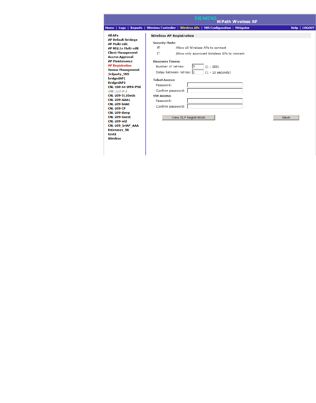
hwc_apstartup.fm
Configuring the Wireless AP
Discovery and registration overview
9034530-02, March 2010
HiPath Wireless Controller, Access Points and Convergence Software V7.11, User Guide 117
3. In the Security Mode section, select one of the following:
• Allow all Wireless APs to connect
• Allow only approved Wireless APs to connect
The Allow all Wireless APs to connect option is selected by default. For
more information, see Section 4.2.5, “Security mode”, on page 115.
4. In the Discovery Timers section, type the discovery timer values in the
following boxes:
• Number of retries
• Delay between retries
The number of retries is limited to 255 in a five-minute discovery period. The
default number of retries is 3, and the default delay between retries is 3
seconds.
5. To save your changes, click Save.
Once the discovery parameters are defined, you can connect the Wireless AP to
a power source.
4.2.6 Connecting the Wireless AP to a power source
and initiating the discovery and registration process
When a Wireless AP is powered on, it automatically begins the discovery and
registration process with the HiPath Wireless Controller.

Configuring the Wireless AP
hwc_apstartup.fm
Adding and registering a Wireless AP manually
9034530-02, March 2010
118 HiPath Wireless Controller, Access Points and Convergence Software V7.11, User Guide
HiPath Wireless AP
The HiPath Wireless AP can be connected and powered in the following ways:
•Power over Ethernet (802.3af):
•PoE enabled switch port
•PoE Injector
•Power by AC adaptor
HiPath Wireless Outdoor AP
The HiPath Wireless Outdoor AP can be connected and powered in the following
ways:
•Power over Ethernet
•PoE enabled switch port
•Power by 48VDC (Direct Current)
•110-230 VAC (Alternating Current)
For more information, see the HiPath Wireless Outdoor Access Point Installation
Guide.
HiPath Wireless 802.11n AP
The HiPath Wireless 802.11n AP can be connected and powered in the following
ways:
•Power over Ethernet
•PoE enabled switch port
•PoE Injector
Note: Use a 1 GB PoE injector to ensure optimum performance of the HiPath
Wireless 802.11n AP.
•Power by AC adaptor
4.3 Adding and registering a Wireless AP manually
An alternative to the automatic discovery and registration process of the Wireless
AP is to manually add and register a Wireless AP to the HiPath Wireless
Controller. The Wireless AP is added with default settings. For more information,
see Section 4.4, “Configuring Wireless AP settings”, on page 119.
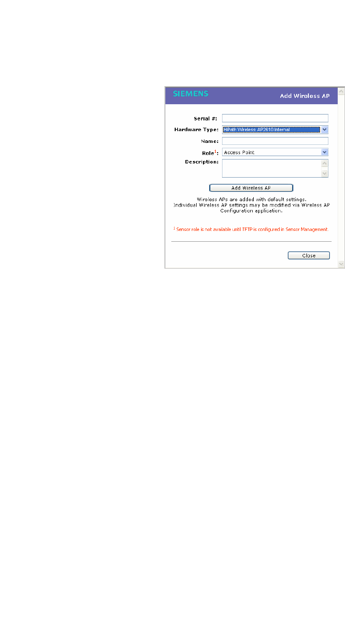
hwc_apstartup.fm
Configuring the Wireless AP
Configuring Wireless AP settings
9034530-02, March 2010
HiPath Wireless Controller, Access Points and Convergence Software V7.11, User Guide 119
To add and register a Wireless AP manually:
1. From the main menu, click Wireless AP Configuration. The HiPath
Wireless AP screen is displayed.
2. Click Add Wireless AP. The Add Wireless AP screen is displayed.
3. In the Serial # box, type the unique identifier.
4. In the Hardware Type drop-down list, click the hardware type of the Wireless
AP.
5. In the Name box, type a unique name for the Wireless AP.
6. In the Role drop-down list, click the Wireless AP’s role — Access Point or
Sensor. The Role drop-down list may be view-only if the Hardware Type you
select only supports the Access Point role. Not all Wireless AP hardware
types support the Sensor role.
7. In the Description box, type descriptive comments for the Wireless AP.
8. Click Add Wireless AP. The Wireless AP is added and registered.
When a Wireless AP is added manually, it is added to the controller database
only and does not get assigned.
9. Click Close.
4.4 Configuring Wireless AP settings
Wireless APs are added with default settings, which you can adjust and configure
according to your network requirements. In addition, you can modify the
properties and the settings for each radio on the Wireless AP.

Configuring the Wireless AP
hwc_apstartup.fm
Configuring Wireless AP settings
9034530-02, March 2010
120 HiPath Wireless Controller, Access Points and Convergence Software V7.11, User Guide
You can also locate and select Wireless APs in specific registration states to
modify their settings. For example, this feature is useful when approving pending
Wireless APs when there are a large number of other Wireless APs that are
already registered. On the Access Approval screen, click Pending to select all
pending Wireless APs, then click Approve to approve all selected Wireless APs.
Configuring Wireless AP settings can include the following processes:
•Modifying a Wireless AP’s status
•Configuring a Wireless AP’s properties
•Configuring Wireless AP radio properties
•Setting up the Wireless AP using static configuration
•Setting up 802.1x authentication for a Wireless AP
When configuring Wireless APs, you can choose to configure individual Wireless
APs or simultaneously configure a group of Wireless APs. For more information,
see Section 4.8, “Configuring Wireless APs simultaneously”, on page 213.
4.4.1 Modifying a Wireless AP’s status
If during the discovery process, the HiPath Wireless Controller security mode was
Allow only approved Wireless APs to connect, then the status of the Wireless
AP is Pending. You must modify the security mode to Allow all Wireless APs to
connect. For more information, see Section 4.2.5, “Security mode”, on page 115.
To modify a Wireless AP's registration status:
1. From the main menu, click Wireless AP Configuration. The HiPath
Wireless AP screen is displayed.
2. In the left pane, click Access Approval. The Access Approval screen is
displayed, along with the registered Wireless APs and their status.
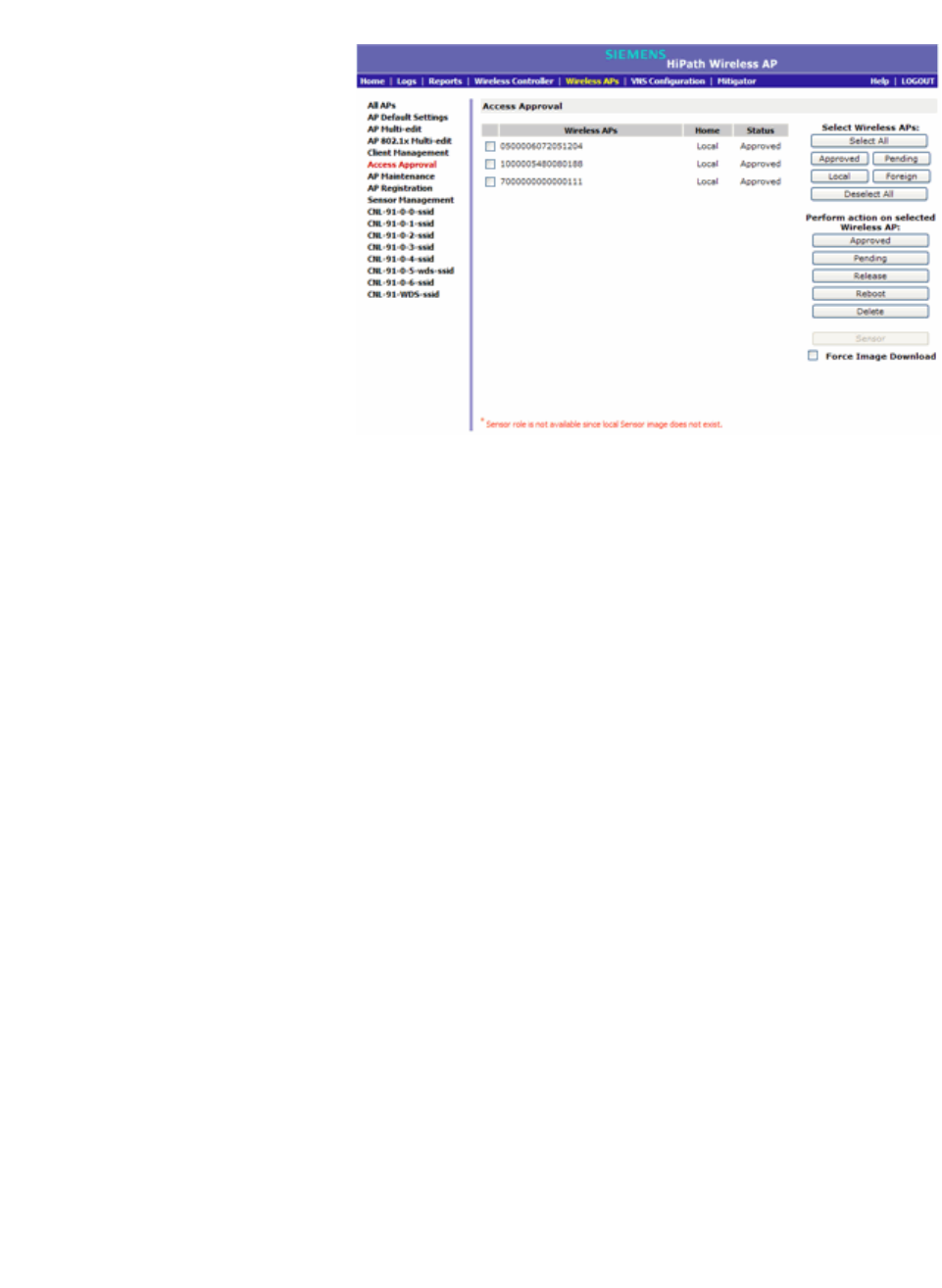
hwc_apstartup.fm
Configuring the Wireless AP
Configuring Wireless AP settings
9034530-02, March 2010
HiPath Wireless Controller, Access Points and Convergence Software V7.11, User Guide 121
3. To select the Wireless APs for status change, do one of the following:
•For a specific Wireless AP, select the corresponding checkbox.
•For Wireless APs by category, click one of the Select Wireless APs
options.
To clear your Wireless AP selections, click Deselect All.
4. Click the appropriate Perform action on selected Wireless APs option:
• Approved – Change a Wireless AP's status to Approved — a Wireless
AP's status changes from Pending to Approved if the AP Registration
screen was configured to register only approved Wireless APs.
• Pending – AP is removed from the Active list, and is forced into
discovery.
• Release – Release foreign Wireless APs after recovery from a failover.
Releasing an AP corresponds to the Availability functionality. For more
information, see Chapter 7, “Availability and session availability”.
• Reboot – Reboot the AP without using Telnet or SSH to access it.
• Delete – Releases the Wireless AP from the HiPath Wireless Controller
and deletes the Wireless AP’s entry in the HiPath Wireless Controller's
management database.

Configuring the Wireless AP
hwc_apstartup.fm
Configuring Wireless AP settings
9034530-02, March 2010
122 HiPath Wireless Controller, Access Points and Convergence Software V7.11, User Guide
•Sensor – The Wireless AP ceases performing RF services and begins
performing scanning services. For more information, see Section 4.9,
“Configuring an AP as a sensor”, on page 215.
Note: Only approve a Wireless AP as a sensor if HiPath HiGuard has
been installed on your HiPath Wireless Manager. For more information,
see the HiPath Wireless Manager User Guide.
Note: Only the Wireless AP 2610/2620 and the Wireless 802.11n AP can
be configured as a sensor.
4.4.2 Configuring a Wireless AP’s properties
Once a Wireless AP has successfully registered, you can then continue to
configure its properties. Configuring Wireless AP properties includes working with
the following Wireless AP tabs:
• AP properties
• VNS Assignment
• Radio 1
• Radio 2
• Static Configuration
•802.1x
You can configure Wireless AP properties based on its role either as an access
point or as a sensor. For more information, see Section 4.9, “Configuring an AP
as a sensor”, on page 215.
4.4.3 AP properties tab configuration
Use the AP Properties tab to view and configure basic Wireless AP properties.
Some of the Wireless AP properties can be viewed and configured via the
Advanced dialog. The following Wireless AP properties on this tab are read-only:
• Serial # – Displays a unique identifier that is assigned during the
manufacturing process.

hwc_apstartup.fm
Configuring the Wireless AP
Configuring Wireless AP settings
9034530-02, March 2010
HiPath Wireless Controller, Access Points and Convergence Software V7.11, User Guide 123
•Host Name – This value, which is based on AP Name, cannot be directly
edited. This value depicts the AP Host-Name value. If the AP Name value
does begin with a number, for example when it is the AP's serial number, the
AP's model is prepended to the value. This value is used for tracking
purposes on the DHCP server.
•Port – Displays the Ethernet port of the HiPath Wireless Controller to which
the Wireless AP is connected.
• Hardware Version – Displays the current version of the Wireless AP
hardware.
• Application Version – Displays the current version of the Wireless AP
software.
• Status:
• Approved – Indicates that the Wireless AP has received its binding key
from the HiPath Wireless Controller after the discovery process.
•If no status is shown, that indicates that the Wireless AP has not yet
successfully been approved for access with the secure HiPath Wireless
Controller.
You can modify the status of a Wireless AP on the Access Approval screen.
For more information, see Section 4.4.1, “Modifying a Wireless AP’s status”,
on page 120.
• Active Clients – Displays the number of wireless devices currently
associated with the Wireless AP.
Wireless AP properties that can be configured on this tab include the following
properties:
•Name – This unique name for the Wireless AP identifies the access point.
The default value is the Wireless AP’s serial number
• Description – This brief description helps identify the access point.
•Role – A Wireless AP can have one of two roles: access point or sensor. A
Wireless AP configured as an access point performs RF services and is
managed by the HiPath Wireless Controller. A Wireless AP that is configured
as a sensor performs scanning services and relays information to HiPath
Wireless Manager HiGuard. When a Wireless AP is configured as a sensor,
the Wireless AP does the following:
•Severs the connection to the HiPath Wireless Controller
•Registers with HiPath Wireless Manager HiGuard
•Performs scanning services

Configuring the Wireless AP
hwc_apstartup.fm
Configuring Wireless AP settings
9034530-02, March 2010
124 HiPath Wireless Controller, Access Points and Convergence Software V7.11, User Guide
When a Wireless AP is configured to the sensor role, its configuration data is
preserved on the HiPath Wireless Controller. The configuration data can only
be modified when the Wireless AP is switched back to the access point role.
In addition, if a Wireless AP is assigned to the sensor role, no additional
Wireless AP tabs are visible.
Note: Only the Wireless AP 2610/2620 and the Wireless 802.11n AP can be
configured as a sensor.
For more information on the sensor role, see Section 4.9, “Configuring an AP
as a sensor”, on page 215.
• Country – This option is only available with certain licenses.
Advanced settings on the AP Properties tab
The Advanced dialog on the AP Properties tab display settings that rarely need
to be configured. For example:
• Poll Timeout – The poll timeout value is measured in seconds. This value
establishes how long a Wireless AP will wait before re-establishing the link
with the HiPath Wireless Controller if it (Wireless AP) does not get an answer
to its polling. The default value is 10 seconds.
•LLDP – LLDP is a protocol that allows a network device to broadcast its
information on a local network to other network devices. This information is
transmitted according to the protocol’s TLVs (Type-Length-Value) elements
in a LLDP packet.
Wireless APs advertise a combination of standard LLDP protocol elements
and specific HiPath information. For more information on the LLDP elements
the Wireless APs broadcast, see the HiPath Wireless Controller, Access
Points and Convergence Software Technical Reference Guide.
When LLDP is enabled for a Wireless AP, you must define the following:
Time to Live – This value, measured in seconds, specifies how long the
receiving device should consider the previous sent information packet to be
accurate.
The Time to Live value is sent in each LLDP packet. The receiving LLDP
device retains the information from the LLDP packet for the duration of the
Time to Live value. If no other LLDP packets arrive after that period, the
information is considered stale and then discarded.
Note: The Time to Live value cannot be directly edited. The Time to Live
value is calculated as four times the Announcement Interval value.
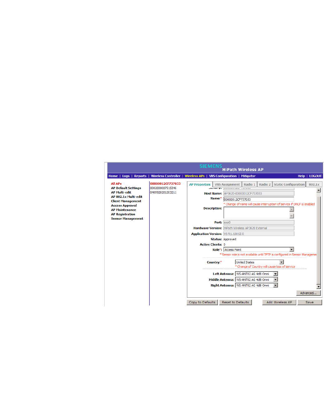
hwc_apstartup.fm
Configuring the Wireless AP
Configuring Wireless AP settings
9034530-02, March 2010
HiPath Wireless Controller, Access Points and Convergence Software V7.11, User Guide 125
Announcement Interval – This value, measured in seconds, is the time
between successive LLDP packets that the Wireless AP advertises. If there
are no changes to the Wireless AP configuration that impact the LLDP
information, the Wireless AP sends a new LLDP packet according to this
schedule.
Announcement Delay – If a change to the Wireless AP configuration occurs
which impacts the LLDP information, the Wireless AP sends an updated
LLDP packet. The Announcement delay is the length of time that delays the
new packet delivery. The delay provides an opportunity for any other potential
configuration changes to be included in the same packet delivery. The
announcement delay helps minimize LLDP packet traffic.
To modify a Wireless AP’s properties as an access point:
1. From the main menu, click Wireless AP Configuration. The HiPath
Wireless AP screen is displayed.
2. In the Wireless AP list, click the Wireless AP whose properties you want to
modify. The AP Properties tab displays Wireless AP information.
3. Modify the Wireless AP’s information:
•Name – Type a unique name for the Wireless AP that identifies the
access point. The default value is the Wireless AP’s serial number.
• Description – Type comments for the Wireless AP.

Configuring the Wireless AP
hwc_apstartup.fm
Configuring Wireless AP settings
9034530-02, March 2010
126 HiPath Wireless Controller, Access Points and Convergence Software V7.11, User Guide
• AP Environment – Click the Wireless AP’s environment — Indoor or
Outdoor.
Note: The AP Environment drop-down is displayed on the AP Properties
tab only if the selected Wireless AP is the HiPath Outdoor Wireless AP.
The HiPath Outdoor Wireless AP can be deployed in both indoor and outdoor
environments.
•Role – Click the role for the Wireless AP, either Access Point or Sensor.
Once the Wireless AP is configured as Sensor, it no longer performs RF
services, and is no longer managed by the HiPath Wireless Controller.
Note: The Role drop-down list is displayed on the AP Properties screen only
if the corresponding Sensor Management settings are configured and only if
the selected Wireless AP is the HiPath Wireless AP 2610/2620 or the
Wireless 802.11n AP. Only the HiPath Wireless AP 2610/2620 and the
Wireless 802.11n AP can perform the role of a sensor.
• Country – Click the country of operation. This option is only available with
some licenses.
4. If the selected Wireless AP model supports external antenna configuration,
click the external applicable antenna you want to assign to the Wireless AP.
The model of the selected Wireless AP determines the available antenna
options.
Note: The antenna you select determines the available channel list and the
maximum transmitting power for the country in which the Wireless AP is
deployed.
Until you select a real antenna type, the external antenna types are set as
follows:
• Antenna-not-selected – This antenna setting is in place for new
external antenna APs added to a new installation or for new external
antenna APs added to an existing installation. This settng allows the
AP to transmit data with a redused Tx Power on a limited set of
channels. In some cases, this setting may cause an empty channel
list on the AP which results in the radio being turned off.
•Default – This antenna setting is in place for existing installations
upgraded to V7.11. As long as this setting is in place, you cannot
change the Max Tx Power setting.
After you select a real antenna, you cannot set the antenna type back to the
Antenna-not-selected or Default settings.
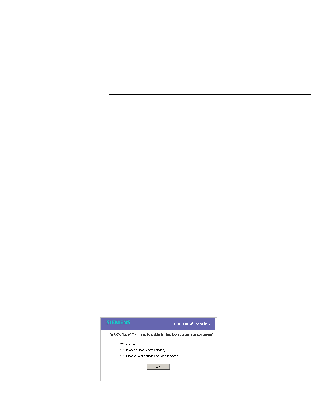
hwc_apstartup.fm
Configuring the Wireless AP
Configuring Wireless AP settings
9034530-02, March 2010
HiPath Wireless Controller, Access Points and Convergence Software V7.11, User Guide 127
5. To modify Wireless AP advanced settings, click Advanced. The Advanced
dialog is displayed.
• Poll Timeout – Type the timeout value, in seconds, for the Wireless AP
to re-establish the link with the HiPath Wireless Controller if it (Wireless
AP) does not get an answer to its polling. The default value is 10 seconds.
Note: If you are configuring session availability, the Poll Timeout value
should be 1.5 to 2 times the Detect link failure value on the AP Properties
screen. For more information, see Section 7.4, “Session availability”, on page
392.
• Telnet Access – Click to enable or disable telnet access to the Wireless
AP.
• Maintain client session in event of poll failure – Select this option (if
using a bridged at AP VNS) if the Wireless AP should remain active if a
link loss with the controller occurs.This option is enabled by default.
• Restart service in the absence of controller – Select this option (if
using a bridged at AP VNS) to ensure the Wireless AP’s radios continue
providing service if the Wireless AP’s connection to the HiPath Wireless
Controller is lost. If this option is enabled, it allows the Wireless AP to start
a bridged at AP VNS even in the absence of a HiPath Wireless Controller.
• Use broadcast for disassociation – Select this option if you want the
Wireless AP to use broadcast disassociation when disconnecting all
clients, instead of disassociating each client one by one. This will affect
the behavior of the Wireless AP under the following conditions:
•If the Wireless AP is preparing to reboot or to enter one of the special
modes (DRM initial channel selection).
•If a BSSID is deactivated or removed on the Wireless AP.
This option is disabled by default.
•LLDP – Click to enable or disable the Wireless AP from broadcasting
LLDP information. This option is disabled by default.
If SNMP is enabled on the HiPath Wireless Controller and you enable
LLDP, the LLDP Confirmation dialog is displayed.

Configuring the Wireless AP
hwc_apstartup.fm
Configuring Wireless AP settings
9034530-02, March 2010
128 HiPath Wireless Controller, Access Points and Convergence Software V7.11, User Guide
•Select one of the following:
• Proceed (not recommended) – Select this option to enable LLDP
and keep SNMP running, and then click OK.
• Disable SNMP publishing, and proceed – Select this option to
enable LLDP and disable SNMP, and then click OK.
For more information on enabling SNMP, see the HiPath Wireless
Controller, Access Points and Convergence Software Maintenance
Guide.
• Announcement Interval – If LLDP is enabled, type how often the
Wireless AP advertises its information by sending a new LLDP packet.
This value is measured in seconds.
If there are no changes to the Wireless AP configuration that impact the
LLDP information, the Wireless AP sends a new LLDP packet according
to this schedule.
Note: The Time to Live value cannot be directly edited. The Time to Live
value is calculated as four times the Announcement Interval value.
• Announcement Delay – If LLDP is enabled, type the announcement
delay. This value is measured in seconds. If a change to the Wireless AP
configuration occurs which impacts the LLDP information, the Wireless
AP sends an updated LLDP packet. The announcement delay is the
length of time that delays the new packet delivery. The announcement
delay helps minimize LLDP packet traffic.
6. Click Close. The Advanced dialog is closed.
7. To save your changes, click Save.
To modify a Wireless AP’s properties as a sensor:
1. From the main menu, click Wireless AP Configuration. The HiPath
Wireless AP screen is displayed.
2. In the Wireless AP list, click the Wireless AP whose properties you want to
modify. The AP Properties tab displays Wireless AP information.
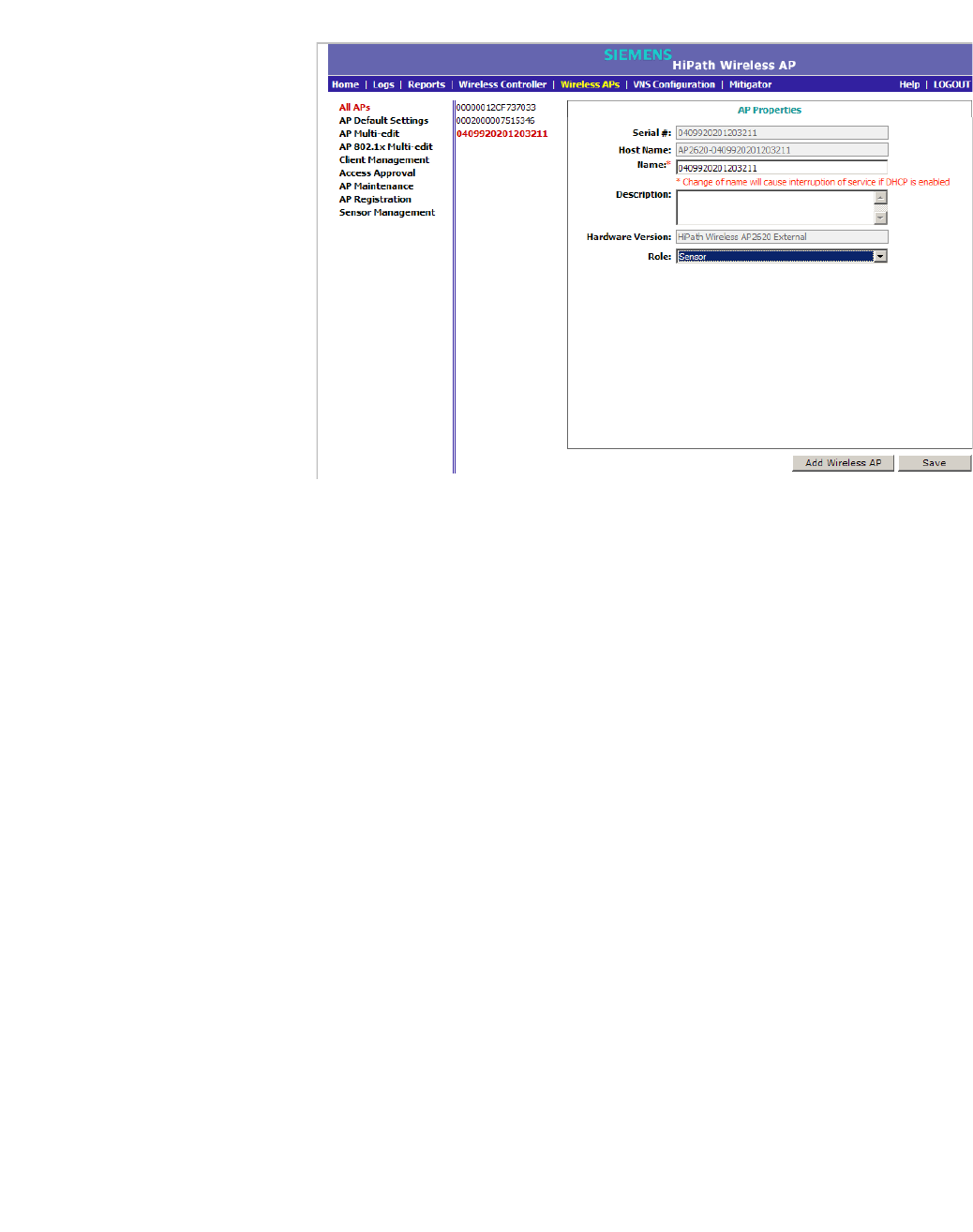
hwc_apstartup.fm
Configuring the Wireless AP
Configuring Wireless AP settings
9034530-02, March 2010
HiPath Wireless Controller, Access Points and Convergence Software V7.11, User Guide 129
3. Modify the Wireless AP’s information:
•Name – Type a unique name for the Wireless AP that identifies the AP.
The default value is the Wireless AP’s serial number.
•Host Name – This value, which is be based on AP Name, cannot be
directly edited. This value depicts the AP Host-Name value. If the AP
Name value does begin with a number, for example when it is the AP's
serial number, the AP's model is prepended to the value. This value is
used for tracking purposes on the DHCP server.
• Description – Type comments for the Wireless AP.
•Role – Click the role for the AP, either Access Point or Sensor. Once the
AP is configured as a Sensor, the AP no longer performs RF services and
is no longer managed by the HiPath Wireless Controller. For more
information, see Section 4.9, “Configuring an AP as a sensor”, on page
215.
4. To save your changes, click Save.
4.4.4 Assigning Wireless AP radios to a VNS
There are three methods of assigning Wireless AP radios to VNSs:
• VNS configuration – When a VNS is configured, you can assign Wireless
AP radios to the VNS through its associated WLAN Service. For more
information, see Section 6.9.1, “Configuring a WLAN Service”, on page 309.
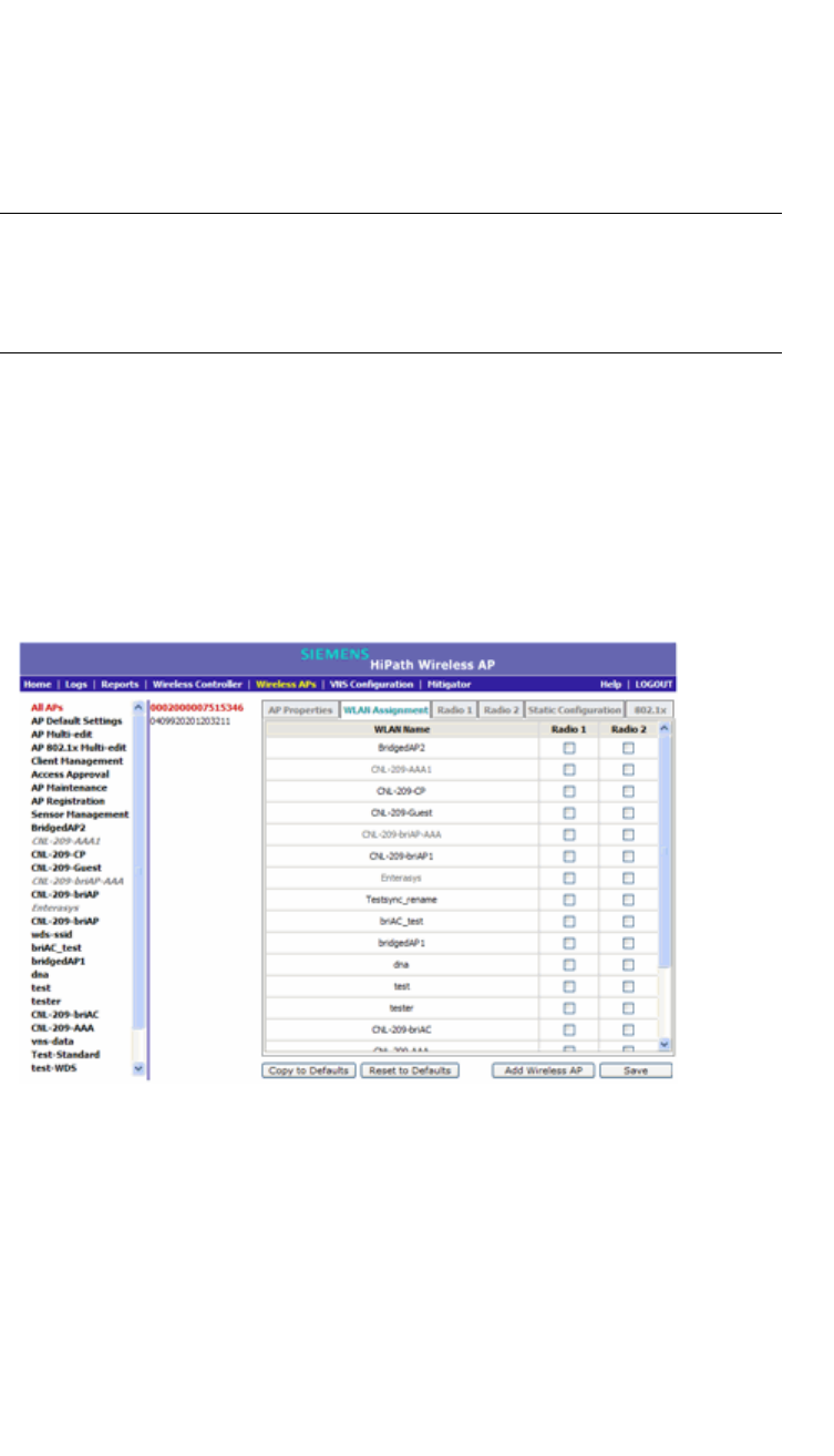
Configuring the Wireless AP
hwc_apstartup.fm
Configuring Wireless AP settings
9034530-02, March 2010
130 HiPath Wireless Controller, Access Points and Convergence Software V7.11, User Guide
• AP Multi-edit – When you configure multiple Wireless APs simultaneously,
you can use the AP Multi-edit feature. For more information, see Section 4.8,
“Configuring Wireless APs simultaneously”, on page 213.
• Wireless AP configuration – When you configure an individual Wireless AP,
you can assign its radios to a specific WLAN Service.
Note: To configure foreign Wireless AP radios to a VNS, use the VNS
configuration method. Foreign Wireless APs are only listed and available for VNS
assignment from the WLAN Services tab. For more information, see Chapter 6,
“Configuring a VNS”.
To assign Wireless AP radios when configuring an individual Wireless AP:
1. From the main menu, click Wireless AP Configuration. The HiPath
Wireless AP screen is displayed.
2. Click the appropriate Wireless AP in the list. The AP Properties tab is
displayed.
3. Click the WLAN Assignment tab.
4. In the Radio 1 and Radio 2 columns, select the Wireless AP radios that you
want to assign for each WLAN Service.
5. To save your changes, click Save.
4.4.5 Configuring Wireless AP radio properties
Modifying Wireless AP radio properties can vary significantly depending on the
model of the Wireless AP your are configuring:

hwc_apstartup.fm
Configuring the Wireless AP
Configuring Wireless AP settings
9034530-02, March 2010
HiPath Wireless Controller, Access Points and Convergence Software V7.11, User Guide 131
•For specific information on modifying a Wireless 802.11n AP, see Section
4.4.5.1, “Modifying Wireless 802.11n AP 3610/3620 radio properties”, on
page 133.
•For specific information on modifying a Wireless AP 2610/2620 or HiPath
Wireless Outdoor AP, see Section 4.4.5.3, “Modifying Wireless AP 2610/2620
radio properties”, on page 152.
Dynamic Radio Management (DRM)
When you modify a Wireless AP’s radio properties, the Dynamic Radio
Management (DRM) functionality of the HiPath Wireless Controller can be used
to help establish the optimum radio configuration for your Wireless APs. DRM is
enabled by default. The HiPath Wireless Controller’s DRM:
•Adjusts transmit power levels to balance coverage between Wireless APs
assigned to the same RF domain and operating on the same channel.
•Scans and coordinates with other Wireless APs to select an optimal operating
channel.
The DRM feature consists of three functions:
• Auto Channel Selection (ACS) – ACS provides an easy way to optimize
channel arrangement based on the current situation in the field. ACS provides
an optimal solution only if it is triggered on all Wireless APs in a deployment.
Triggering ACS on a single Wireless AP or on a subset of Wireless APs
provides a useful but suboptimal solution. Also, ACS only relies on the
information observed at the time it is triggered. Once a Wireless AP has
selected a channel, it will remain operating on that channel until the user
changes the channel or triggers ACS.
ACS can be triggered by one of the following events:
•A new Wireless AP registers with the HiPath Wireless Controller and the
AP Default Settings channel is Auto.
•A user selects Auto from the Request New Channel drop-down list on
the Wireless AP’s radio configuration tabs.
•A user selects Auto from the Channel drop-down list on the AP
Multi-edit screen.
•If Dynamic Channel Selection (DCS) is enabled in active mode and a
DCS threshold is exceeded.
•A Wireless AP detects radar on its current operating channel and it
employs ACS to select a new channel.

Configuring the Wireless AP
hwc_apstartup.fm
Configuring Wireless AP settings
9034530-02, March 2010
132 HiPath Wireless Controller, Access Points and Convergence Software V7.11, User Guide
• Channel Plan – If ACS is enabled, you can define a channel plan for the
Wireless AP. Defining a channel plan allows you to limit which channels
are available for use during an ACS scan. For example, you may want to
avoid using specific channels because of low power, regulatory domain,
or radar interference. Select from the following options:
Depending on the radio used, when defining a channel plan you can
either create your customized channel plan by selecting individual
channels or you can select a default 3 or 4 channel plan.
You can use the channel plan to avoid transmission overlap on 40MHz
channels of the Wireless 802.11n APs. To avoid channel overlap between
Wireless 802.11n APs that operate on 40MHz channels, configure the
channel plan for the 5 GHz radio band to use every other channel
available.
If using half of the available channels is not an option for your
environment, do not configure a channel plan. Instead, allow ACS to
select from all available channels. This alternate solution may contribute
to increased congestion on the extension channels.
Note: ACS in the 2.4GHz radio band with 40MHz channels is not recommended
due to severe co-channel interference.
• Dynamic Channel Selection (DCS) – DCS allows a Wireless AP to monitor
traffic and noise levels on the channel on which the Wireless AP is currently
operating. DCS can operate in two modes:
• Monitor – When DCS is enabled in monitor mode and traffic or noise
levels exceed the configured DCS thresholds, an alarm is triggered and
an information log is generated. The DCS monitor alarm is used for
evaluating the RF environment of your deployed Wireless APs.
•Active – When DCS is enabled in active mode and traffic or noise levels
exceed the configured DCS thresholds, an alarm is triggered and an
information log is generated. In addition, the Wireless AP will cease
operating on the current channel and ACS is employed to automatically
select an alternate channel for the Wireless AP to operate on. DCS will
not trigger channel changes on neighboring Wireless APs.
Note: If DCS is enabled, DCS statistics can be viewed in the Wireless
Statistics by Wireless APs display. For more information, see Chapter 11,
“Working with reports and displays”.
• Auto Tx Power Control (ATPC) – ATPC guarantees your LAN a stable RF
environment by automatically adapting transmission power signals according
to the coverage provided by the Wireless APs. ATPC can be either enabled
or disabled.

hwc_apstartup.fm
Configuring the Wireless AP
Configuring Wireless AP settings
9034530-02, March 2010
HiPath Wireless Controller, Access Points and Convergence Software V7.11, User Guide 133
When you disable ATPC, you are given the option of automatically adjusting
the Max Tx Power setting to match the Current Tx Power Level. In the case
of AP Multi-edit, if you reply yes, then each individual Wireless AP's Max Tx
Power setting will be adjusted to correspond with its Current Tx Power Level
in the database.
4.4.5.1 Modifying Wireless 802.11n AP 3610/3620 radio
properties
The Wireless 802.11n AP 3610/3620 is a 802.11n-compliant access point. The
following section describes how to modify a Wireless 802.11n AP.
For information on how to modify a Wireless AP 2610/2620 or the HiPath
Wireless Outdoor AP, see Section 4.4.5.3, “Modifying Wireless AP 2610/2620
radio properties”, on page 152.
Channel bonding
Channel bonding improves the effective throughput of the wireless LAN. In
contrast to the Wireless AP 26xx which uses radio channel spacings that are only
20MHz wide, the Wireless 802.11n AP can use two channels at the same time to
create a 40MHz wide channel. To achieve a 40MHz channel width, the Wireless
802.11n AP employs channel bonding — two 20MHz channels at the same time.
The 40MHz channel width is achieved by bonding the primary channel (20MHz)
with an extension channel that is either 20MHz above (bonding up) or 20MHz
below (bonding down) of the primary channel.
Depending on the Radio, channel bonding can be predefined:
• Radio 1 – Bonding pairs are predefined.
• Radio 2 – Channels can bond up or down as long as the band edge is not
exceeded, but some channels have predefined bonding directions.
Channel bonding is enabled by selecting the Channel Width on the Radio tabs.
When selecting Channel Width, the following options are available:
•20MHz – Channel bonding is not enabled:
•802.11n clients use the primary channel (20MHz)
•Non-802.11n clients, as well as beacons and multicasts, use the
802.11a/b/g radio protocols.
•40MHz – Channel bonding is enabled:
•802.11n clients that support the 40MHz frequency can use 40MHz,
20MHz, or the 802.11a/b/g radio protocols.
•802.11n clients that do not support the 40MHz frequency can use 20MHz
or the 802.11a/b/g radio protocols.

Configuring the Wireless AP
hwc_apstartup.fm
Configuring Wireless AP settings
9034530-02, March 2010
134 HiPath Wireless Controller, Access Points and Convergence Software V7.11, User Guide
•Non-802.11n clients, beacons, and multicasts use the 802.11a/b/g radio
protocols.
•If the primary channel allows for both bonding types (up and down), you
can select the channel bonding type from the Channel Bonding drop-
down list.
•If the primary channel allows for only one of the bonding types (up or
down), that channel bond type is displayed in the Channel Bonding
drop-down list.
•Auto – Channel bonding is automatically enabled or disabled, switching
between 20MHz and 40MHz, depending on how busy the extension channel
is. If the extension channel is busy above a prescribed threshold percentage,
which is defined in the 40MHz Channel Busy Threshold box, channel
bonding is disabled.
Channel selection — primary and extension
The primary channel of the Wireless 802.11n AP is selected from the Request
New Channel drop-down list. If auto is selected, the ACS feature selects the
primary channel. Depending on the primary channel that is selected, channel
bonding may be allowed: up, down, both, or neither.
Guard interval
The guard intervals ensure that individual transmissions do not interfere with one
another. The Wireless 802.11n AP provides a shorter guard interval that
increases the channel throughput. When a 40MHz channel is used, you can
select the guard interval to improve the channel efficiency. The guard interval is
selected from the Guard Interval drop-down list. Longer guard periods reduce
the channel efficiency.
Aggregate MSDU and MPDU
The Wireless 802.11n AP provides aggregate Mac Service Data Unit (MSDU)
and aggregate Mac Protocol Data Unit (MPDU) functionality, which combines
multiple frames together into one larger frame for a single delivery. This
aggregation reduces the overhead of the transmission and results in increased
throughput. The aggregate methods are enabled and defined selected from the
Aggregate MSDUs and Aggregate MPDUs drop-down lists.
Antenna selection
The Wireless 802.11n AP has three antennas: left, middle, and right. The
illustration below identifies the left and right antennas.
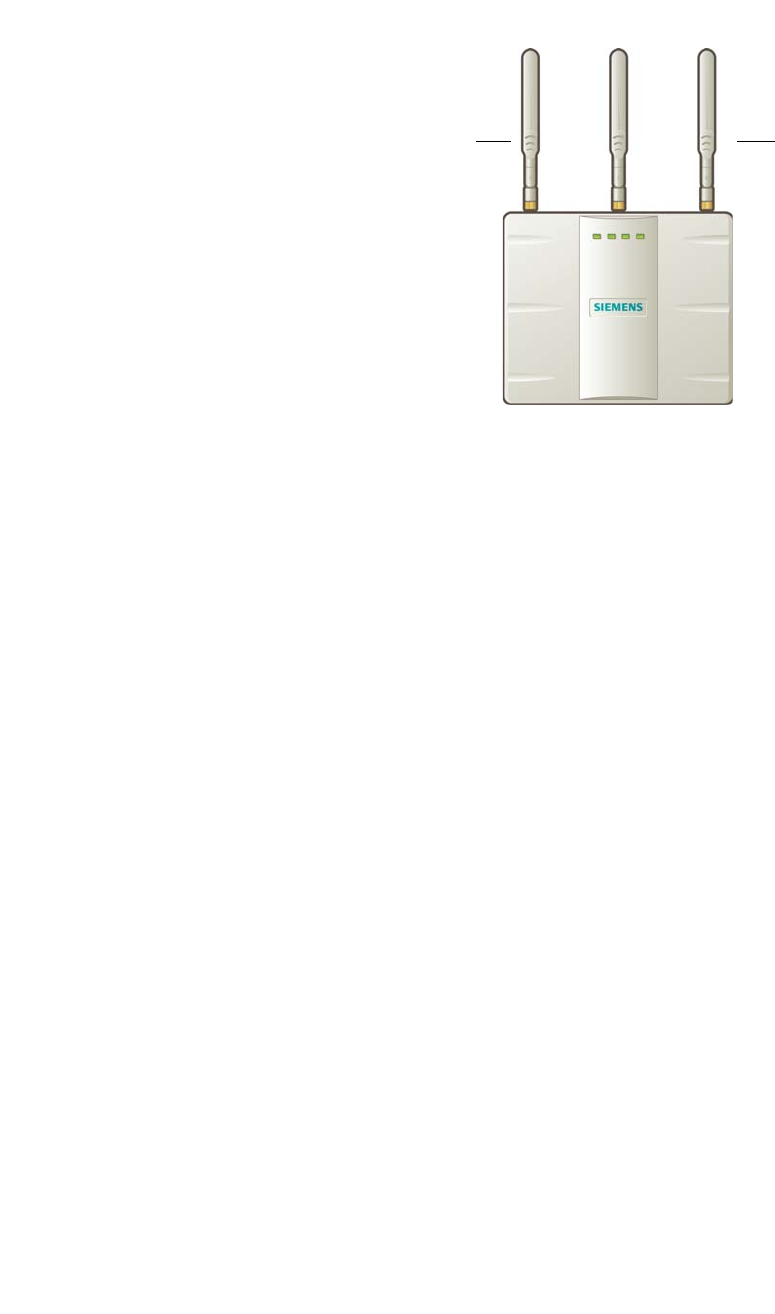
hwc_apstartup.fm
Configuring the Wireless AP
Configuring Wireless AP settings
9034530-02, March 2010
HiPath Wireless Controller, Access Points and Convergence Software V7.11, User Guide 135
The Wireless 802.11n AP is configured, by default, to transmit on all three
antennas. Depending on your deployment requirements, you can configure the
Wireless 802.11n AP to transmit on specific antennas. You can configure the
Wireless 802.11n AP to transmit on specific antennas for both radios, including
all the available modes:
• Radio 1 – a, a/n modes
• Radio 2 – b, b/g, b/g/n modes
When you configure the Wireless 802.11n AP to use specific antennas, the
following occurs:
•Transmission power is recalculated – The Current Tx Power Level value for
the radio is automatically adjusted to reflect the recent antenna configuration.
It takes approximately 30 seconds for the change to the Current Tx Power
Level value to be reflected in the HiPath Wireless Assistant.
•Radio is reset – The radio is reset causing client connections on this radio to
be lost.
To modify Wireless 802.11n AP radio properties:
1. From the main menu, click Wireless AP Configuration. The HiPath
Wireless AP screen is displayed.
2. Click the appropriate Wireless 802.11n AP in the list. The AP Properties tab
is displayed.
3. Click the Radio tab you want to modify.
Each Radio tab displays the radio settings for each radio on the Wireless AP.
If the Radio has been assigned to a VNS, the VNS names and MAC
addresses are displayed in the Base Settings section. The HiPath Wireless
Controller can support the following active VNSs:
•C5110 – Up to 128 VNSs
Left antenna Right antenna
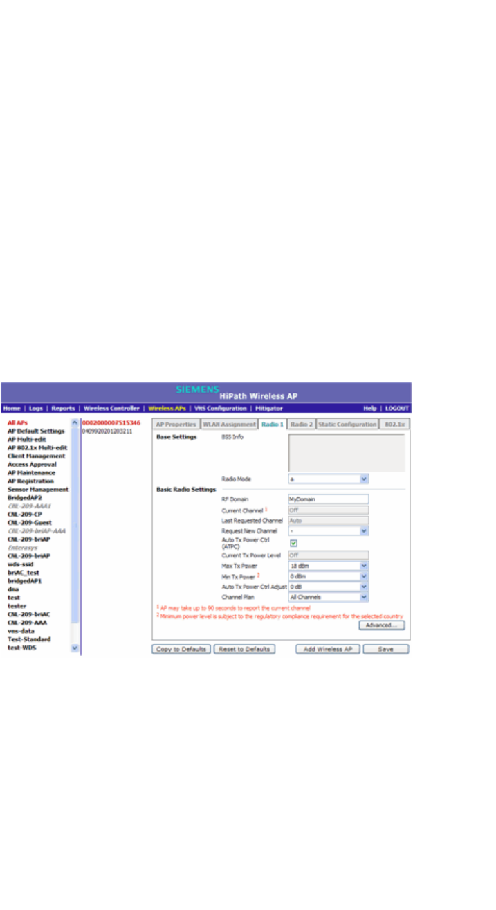
Configuring the Wireless AP
hwc_apstartup.fm
Configuring Wireless AP settings
9034530-02, March 2010
136 HiPath Wireless Controller, Access Points and Convergence Software V7.11, User Guide
•C4110 – Up to 64 VNSs
•C2400 – Up to 64 VNSs
•C20 – Up to 8 VNSs
•C20N – Up to 8 VNSs
•CRBT8210 – Up to 16 VNSs
•CRBT8110 – Up to 8 VNSs
The Wireless AP radios can be assigned to each of the configured VNSs in a
system. Each radio can support eight WLAN assignments, corresponding to
the number of SSIDs it can support. Once a radio has all 8 slots assigned, it
is no longer eligible for further assignment.
The BSS Info section is view-only. After VNS configuration, the Basic
Service Set (BSS) section displays the MAC address on the Wireless AP for
each WLAN Service as well as the SSIDs of the WLAN Services to which this
radio has been assigned.
4. If applicable, click the Radio 1 tab.
5. In the Base Settings section, do the following:
• Radio Mode – Click one of the following radio options:
•off – Click to disable Radio 1.
•a – Click to enable the 802.11a mode of Radio 1 without 802.11n
capability.

hwc_apstartup.fm
Configuring the Wireless AP
Configuring Wireless AP settings
9034530-02, March 2010
HiPath Wireless Controller, Access Points and Convergence Software V7.11, User Guide 137
•a/n – Click to enable the 802.11a mode of Radio 1 with 802.11n
capability.
Note: Depending on the radio modes you select, some of the radio
settings may not be available for configuration. The Wireless AP
hardware version dictates the available radio modes.
• Channel Width – Click the channel width for the radio:
•20MHz – Click to allow 802.11n clients to use the primary channel
(20MHz) and non-802.11n clients, as well as beacons and multicasts,
to use the 802.11b/g radio protocols.
•40MHz – Click to allow 802.11n clients that support the 40MHz
frequency to use 40MHz, 20MHz, or the 802.11b/g radio protocols.
802.11n clients that do not support the 40MHz frequency can use
20MHz or the 802.11b/g radio protocols and non-802.11n clients,
beacons, and multicasts use the 802.11b/g radio protocols.
•Auto – Click to automatically switch between 20MHz and 40MHz
channel widths, depending on how busy the extension channel is.
6. In the Basic Radio Settings section, do the following:
•RF Domain – Type a string that uniquely identifies a group of APs that
cooperate in managing RF channels and transmission power levels. The
maximum length of the string is 16 characters. The RF Domain is used to
identify a group of Wireless APs.
• Request New Channel – Click the wireless channel you want the
Wireless 802.11n AP to use to communicate with wireless devices.
Click Auto to request the ACS to search for a new channel for the
Wireless AP, using a channel selection algorithm. This forces the
Wireless AP to go through the auto-channel selection process again.
Note: ACS in the 2.4GHz radio band with 40MHz channels is not
recommended due to severe co-channel interference.
Depending on the regulatory domain (based on country), some channels
may be restricted. The default value is based on North America. For more
information, see Appendix B.

Configuring the Wireless AP
hwc_apstartup.fm
Configuring Wireless AP settings
9034530-02, March 2010
138 HiPath Wireless Controller, Access Points and Convergence Software V7.11, User Guide
• Auto Tx Power Ctrl (ATPC) – Select to enable ATPC. ATPC
automatically adapts transmission power signals according to the
coverage provided by the Wireless APs. After a period of time, the system
will stabilize itself based on the RF coverage of your Wireless APs.
Note: If you disable ATPC, you can still choose to maintain using the
current Tx power setting ATPC had established. If you elect to maintain
using the ATPC power setting, the displayed Current Tx Power Level
value becomes the new Max Tx Power value for the Wireless AP.
• Channel Bonding – Click the bonding method, Up or Down. The primary
channel (20MHz) is bonded with an extension channel that is either
20MHz above (bonding up) or 20MHz below (bonding down) of the
primary channel. Note that the available choices for Channel Bonding in
the drop-down list may depend on the channel first selected in Request
New Channel.
• Guard Interval – Click a guard interval, Long or Short, when a 40MHz
channel is used. It is recommended to use a short guard interval in small
rooms (for example, a small office space) and a long guard interval in
large rooms (for example, a conference hall).
•Max Tx Power – Click the maximum Tx power level to which the range of
transmit power can be adjusted: 0 to 24 dBm. It is recommended to use
24 dBm to not limit the potential Tx power level range that can be used.
Note: In reality, the lowest achievable power level is 5 dBm for the
Wireless 802.11n AP 3610 and 2 dBm for the Wireless 802.11n AP 3620.
If you assign a lower value, it will automatically default to the lowest
achievable level.
•Min Tx Power – If ATPC is enabled, click the minimum Tx power level to
which the range of transmit power can be adjusted. It is recommended to
use the lowest value available to not limit the potential Tx power level
range that can be used.
Note: The Minimum Tx Power level is subject to the regulatory
compliance requirement for the selected country.
• Auto Tx Power Ctrl Adjust – If ATPC is enabled, click the Tx power level
that can be used to adjust the ATPC power levels that the system has
assigned. It is recommended to use 0 dB during your initial configuration.
If you have an RF plan that recommended Tx power levels for each
Wireless AP, compare the actual Tx power levels your system has

hwc_apstartup.fm
Configuring the Wireless AP
Configuring Wireless AP settings
9034530-02, March 2010
HiPath Wireless Controller, Access Points and Convergence Software V7.11, User Guide 139
assigned against the recommended values your RF plan has provided.
Use the Auto Tx Power Ctrl Adjust value to achieve the recommended
values.
Note:
• Current Channel – This field is view only. It displays the actual channel
the ACS has assigned to the Wireless AP radio. The Current Channel
value and the Last Requested Channel value may be different because
the ACS automatically assigns the best available channel to the Wireless
AP, ensuring that a Wireless AP’s radio is always operating on the best
available channel.
• Last Requested Channel – This field is view only. This field displays
the last wireless channel that you had selected to communicate with the
wireless devices.
• Current Tx Power Level – This field is view only. It displays the actual
Tx power level assigned to the Wireless AP radio.
• Channel Plan – If ACS is enabled, you can define a channel plan for the
Wireless AP. Defining a channel plan allows you to limit which channels
are available for use during an ACS scan. For example, you may want to
avoid using specific channels because of low power, regulatory domain,
or radar interference. Click one of the following:
• All channels – ACS scans all channels for an operating channel and
returns both DFS and non-DFS channels, if available.
• All Non-DFS Channels – ACS scans all non-DFS channels for an
operating channel. This selection is available when there is at least
one DFS channel supported for the selected country.
•Custom – To configure individual channels from which the ACS will
select an operating channel, click Configure. The Custom Channel
Plan dialog displays. By default, all channels participate in the
channel plan. Click the individual channels you want to include in the
channel plan. To select contiguous channels, use the Shift key. To
select multiple, non-contiguous channels in the list, use the CTRL
key. Click OK to save the configuration.
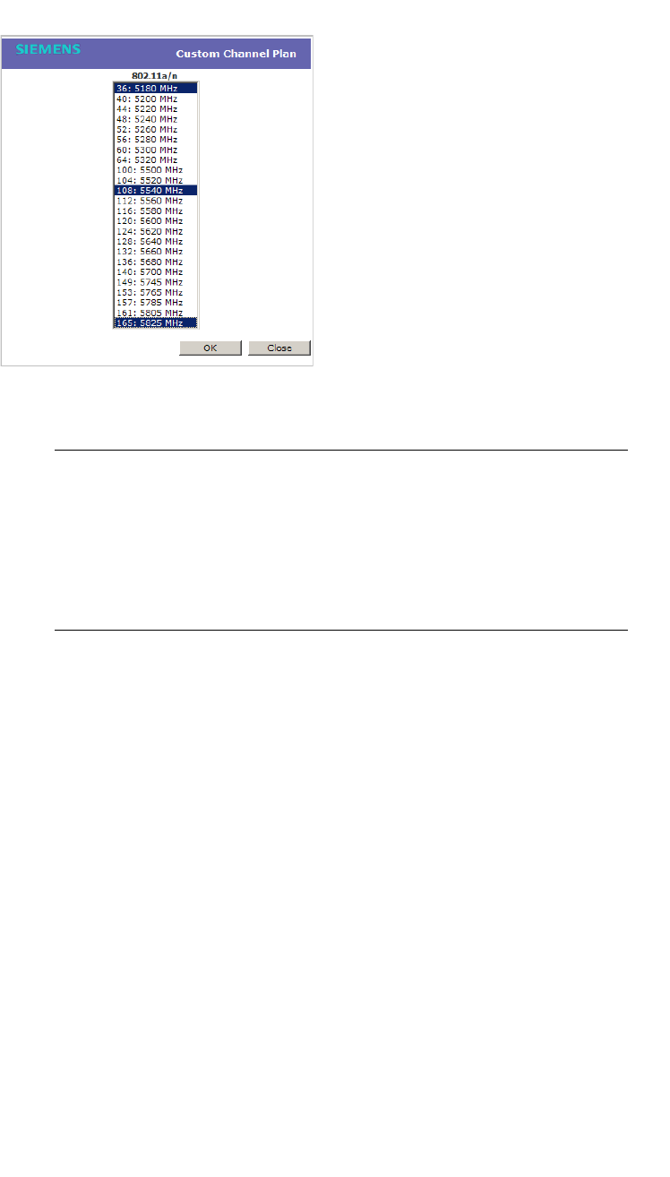
Configuring the Wireless AP
hwc_apstartup.fm
Configuring Wireless AP settings
9034530-02, March 2010
140 HiPath Wireless Controller, Access Points and Convergence Software V7.11, User Guide
• Antenna Selection – Click the antenna, or antenna combination, you
want to configure on this radio.
Note: When you configure the Wireless 802.11n AP to use specific
antennas, the transmission power is recalculated; the Current Tx Power
Level value for the radio is automatically adjusted to reflect the recent
antenna configuration. It takes approximately 30 seconds for the change
to the Current Tx Power Level value to be reflected in the HiPath
Wireless Assistant. Also, the radio is reset which may cause client
connections on this radio to be lost.
7. To modify Radio 1 advanced settings, click Advanced. The Advanced
dialog is displayed.
8. In the Advanced dialog Base Settings section, do the following:
• DTIM Period – Type the desired DTIM (Delivery Traffic Indication
Message) period — the number of beacon intervals between two DTIM
beacons. To ensure the best client power savings, use a large number.
Use a small number to minimize broadcast and multicast delay. The
default value is 5.
• Beacon Period – Type the desired time, in milliseconds, between
beacon transmissions. The default value is 100 milliseconds.
• RTS/CTS Threshold – Type the packet size threshold, in bytes, above
which the packet will be preceded by an RTS/CTS (Request to
Send/Clear to Send) handshake. The default value is 2346, which means
all packets are sent without RTS/CTS. Reduce this value only if
necessary.

hwc_apstartup.fm
Configuring the Wireless AP
Configuring Wireless AP settings
9034530-02, March 2010
HiPath Wireless Controller, Access Points and Convergence Software V7.11, User Guide 141
• Frag. Threshold – Type the fragment size threshold, in bytes, above
which the packets will be fragmented by the Wireless AP prior to
transmission. The default value is 2346, which means all packets are sent
unfragmented. Reduce this value only if necessary.
• Max % of non-unicast traffic per Beacon period – Enter the maximum
percentage of time that the AP will transmit non-unicast packets
(broadcast and multicast traffic) for each configured Beacon Period. For
each non-unicast packet transmitted, the system calculates the airtime
used by eack packet and drops all packets that exceed the configured
maximum percentage. By restricting non-unicast traffic, you limit the
impact of broadcasts and multicasts on overall system performance.
• Maximum Distance – Enter a value from 100 to 15,000 meters that
identifies the maximum link distance between APs that participate in a
WDS. This value ensures that the acknowledgement of communication
between APs does not exceed the timeout value predefined by the 802.11
standard. The default value is 100 meters. If the link distance between
APs is greater than 100 meters, configure the maximum distance up to
15,000 meters so that the software increases the timeout value
proportionally with the distance between APs.
Do not change the default setting for the radio that provides service to
802.11 clients only.
9. In the Advanced dialog Basic Radio Settings section, do the following:
• Dynamic Channel Selection – To enable Dynamic Channel Selection,
click one of the following:
• Monitor Mode – If traffic or noise levels exceed the configured DCS
thresholds, an alarm is triggered and an information log is generated.
• Active Mode – If traffic or noise levels exceed the configured DCS
thresholds, an alarm is triggered and an information log is generated.
In addition, the Wireless AP will cease operating on the current
channel and ACS is employed to automatically select an alternate
channel for the Wireless AP to operate on.
• DCS Noise Threshold – Type the noise interference level, measured
in dBm, after which ACS will scan for a new operating channel for the
Wireless AP if the threshold is exceeded.
• DCS Channel Occupancy Threshold – Type the channel utilization
level, measured as a percentage, after which ACS will scan for a new
operating channel for the Wireless AP if the threshold is exceeded.

Configuring the Wireless AP
hwc_apstartup.fm
Configuring Wireless AP settings
9034530-02, March 2010
142 HiPath Wireless Controller, Access Points and Convergence Software V7.11, User Guide
• DCS Update Period – Type the time, measured in minutes that
determines the period during which the Wireless AP averages the
DCS Noise Threshold and DCS Channel Occupancy Threshold
measurements. If either one of these thresholds is exceeded, then
the Wireless AP will trigger ACS.
10. In the Advanced dialog 11n Settings section, do the following:
• Protection Mode – Click a protection mode: Enabled or Disabled. This
protects high throughput transmissions on primary channels from non-
11n APs and clients. Click Disabled if non-11n APs and clients are not
expected. Click Enabled if you expect many non-11n APs and clients.
The overall throughput is reduced when Protection Mode is enabled.
• 40MHz Protection Mode – Click a protection type, CTS Only or RTS-
CTS, or None, when a 40MHz channel is used. This protects high
throughput transmissions on extension channels from interference from
non-11n APs and clients.
• 40MHz Prot. Channel Offset – Select a 20MHz channel offset if the
deployment is using channels that are 20MHz apart (for example, using
channels 1, 5, 9, and 13) or a 25MHz channel offset if the deployment is
using channels that are 25MHz apart (for example, using channels 1, 6,
and 11).
• 40MHz Channel Busy Threshold – Type the extension channel
threshold percentage, which if exceeded, will disable transmissions on
the extension channel (40MHz).
• Aggregate MSDUs – Click an aggregate MSDU mode: Enabled or
Disabled. Aggregate MSDU increases the maximum frame transmission
size.
• Aggregate MSDU Max Length – Type the maximum length of the
aggregate MSDU. The value range is 2290-4096 bytes.
• Aggregate MPDUs – Click an aggregate MPDU mode: Enabled or
Disabled. Aggregate MPDU provides a significant improvement in
throughput.
• Aggregate MPDU Max Length – Type the maximum length of the
aggregate MPDU. The value range is 1024-65535 bytes.
• Agg. MPDU Max # of Sub-frames – Type the maximum number of
sub-frames of the aggregate MPDU. The value range is 2-64.
• ADDBA Support – Click an ADDBA support mode: Enabled or
Disabled. ADDBA, or block acknowledgement, provides
acknowledgement of a group of frames instead of a single frame. ADDBA
Support must be enabled if Aggregate APDU is enable.
11. Click Close. The Advanced dialog is closed.

hwc_apstartup.fm
Configuring the Wireless AP
Configuring Wireless AP settings
9034530-02, March 2010
HiPath Wireless Controller, Access Points and Convergence Software V7.11, User Guide 143
12. Click Save to save your changes.
13. If applicable, click the Radio 2 tab.
14. In the Base Settings section, do the following:
• Radio Mode – Click one of the following radio options:
•off – Click to disable Radio 2.
•b – Click to enable the 802.11b-only mode of Radio 2. If selected, the
AP will use only 11b (CCK) rates with all associated clients.
•b/g – Click to enable both the 802.11g mode and the 802.11b mode
of Radio 2. If selected, the AP will use 11b (CCK) and 11g-specific
(OFDM) rates with all of the associated clients. The AP will not
transmit or receive 11n rates.
• b/g/n – Click to enable b/g/n modes of Radio 2. If selected, the AP
will use all available 11b, 11g, and 11n rates.
Note: Depending on the radio modes you select, some of the radio
settings may not be available for configuration.
• Channel Width – Click the channel width for the radio:
•20MHz – Click to allow 802.11n clients to use the primary channel
(20MHz) and non-802.11n clients, beacons, and multicasts to use the
802.11b/g radio protocols.
•40MHz – Click to allow 802.11n clients that support the 40MHz
frequency to use 40MHz, 20MHz, or the 802.11b/g radio protocols.
802.11n clients that do not support the 40MHz frequency can use
20MHz or the 802.11b/g radio protocols and non-802.11n clients,
beacons, and multicasts use the 802.11b/g radio protocols.
•Auto – Click to automatically switch between 20MHz and 40MHz
channel widths, depending on how busy the extension channel is.
15. In the Basic Radio Settings section, do the following:
•RF Domain – Type a string that uniquely identifies a group of APs that
cooperate in managing RF channels and transmission power levels. The
maximum length of the string is 16 characters. The RF Domain is used to
identify a group of Wireless APs.
• Request New Channel – Click the wireless channel you want the
Wireless 802.11n AP to use to communicate with wireless devices.

Configuring the Wireless AP
hwc_apstartup.fm
Configuring Wireless AP settings
9034530-02, March 2010
144 HiPath Wireless Controller, Access Points and Convergence Software V7.11, User Guide
Click Auto to request the ACS to search for a new channel for the
Wireless 802.11n AP, using a channel selection algorithm. This forces the
Wireless 802.11n AP to go through the auto-channel selection process
again.
Note: ACS in the 2.4GHz radio band with 40MHz channels is not
recommended due to severe co-channel interference.
Depending on the regulatory domain (based on country), some channels
may be restricted. For more information, see Appendix B.
• Auto Tx Power Ctrl (ATPC) – Select to enable ATPC. ATPC
automatically adapts transmission power signals according to the
coverage provided by the Wireless APs. After a period of time, the system
will stabilize itself based on the RF coverage of your Wireless APs.
Note: If you disable ATPC, you can still choose to maintain using the
current Tx power setting ATPC had established. If you elect to maintain
using the ATPC power setting, the displayed Current Tx Power Level
value becomes the new Max Tx Power value for the Wireless AP.
• Channel Bonding – Click the bonding method, Up or Down. The primary
channel (20MHz) is bonded with an extension channel that is either
20MHz above (bonding up) or 20MHz below (bonding down) of the
primary channel. Note that the available choices for Channel Bonding in
the drop-down list may depend on the channel first selected in Request
New Channel.
• Guard Interval – Click a guard interval, Long or Short, when a 40MHz
channel is used. It is recommended to use a short guard interval in small
rooms (for example, a small office space) and a long guard interval in
large rooms (for example, a conference hall).
•Max Tx Power – Click the maximum Tx power level to which the range of
transmit power can be adjusted: 0 to 23 dBm. It is recommended to use
23 dBm to not limit the potential Tx power level range that can be used.
Note: The lowest Max Tx Power level that can be assigned is 5 dBm for
the Wireless 802.11n AP 3610 and 4 dBm for the Wireless 802.11n AP
3620; a lower Max Tx Power level assignment will automatically default
to the lowest allowed levels.

hwc_apstartup.fm
Configuring the Wireless AP
Configuring Wireless AP settings
9034530-02, March 2010
HiPath Wireless Controller, Access Points and Convergence Software V7.11, User Guide 145
• Min Tx Power – If ATPC is enabled, click the minimum Tx power level to
which the range of transmit power can be adjusted. It is recommended to
use the lowest value available to not limit the potential Tx power level
range that can be used.
Note: The Minimum Tx Power level is subject to the regulatory
compliance requirement for the selected country.
• Auto Tx Power Ctrl Adjust – If ATPC is enabled, click the Tx power level
that can be used to adjust the ATPC power levels that the system has
assigned. It is recommended to use 0 dB during your initial configuration.
If you have an RF plan that recommends Tx power levels for each
Wireless AP, compare the actual Tx power levels your system has
assigned against the recommended values your RF plan has provided.
Use the Auto Tx Power Ctrl Adjust value to achieve the recommended
values.
Note:
• Current Channel – This field is view only. It displays the actual channel
the ACS has assigned to the Wireless AP radio. The Current Channel
value and the Last Requested Channel value may be different because
the ACS automatically assigns the best available channel to the Wireless
AP, ensuring that a Wireless AP’s radio is always operating on the best
available channel.
• Last Requested Channel – This field is view only. This field displays
the last wireless channel that you had selected to communicate with the
wireless devices.
• Current Tx Power Level – This field is view only. It displays the actual
Tx power level assigned to the Wireless AP radio.
• Channel Plan – If ACS is enabled, you can define a channel plan for the
Wireless AP. Defining a channel plan allows you to limit which channels
are available for use during an ACS scan. For example, you may want to
avoid using specific channels because of low power, regulatory domain,
or radar interference. Click one of the following:
• 3 Channel Plan – ACS will scan the following channels: 1, 6, and 11
in North America, and 1, 7, and 13 in most other parts of the world.
• 4 Channel Plan – ACS will scan the following channels: 1, 4, 7, and
11 in North America, and 1, 5, 9, and 13 in most other parts of the
world.
•Auto – ACS will scan the default channel plan channels: 1, 6, and 11
in North America, and 1, 5, 9, and 13 in most other parts of the world.
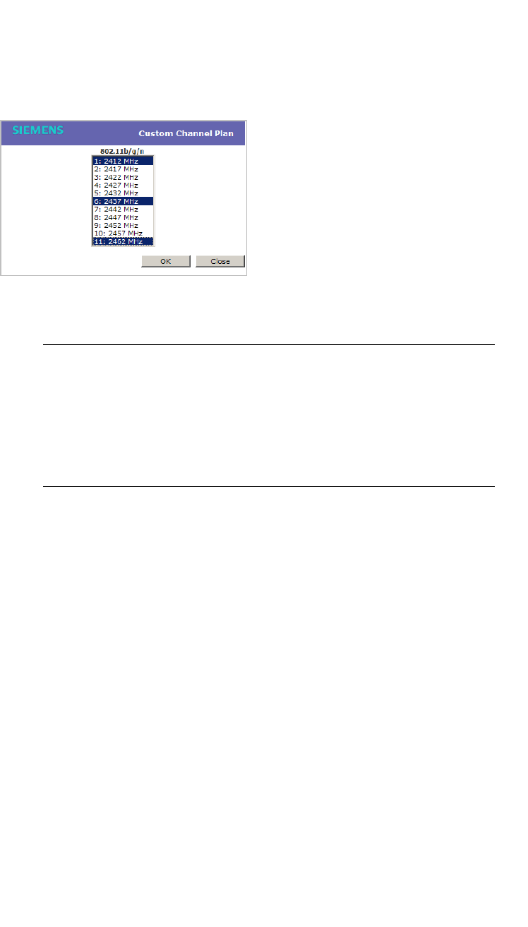
Configuring the Wireless AP
hwc_apstartup.fm
Configuring Wireless AP settings
9034530-02, March 2010
146 HiPath Wireless Controller, Access Points and Convergence Software V7.11, User Guide
•Custom – If you want to configure individual channels from which the
ACS will select an operating channel, click Configure. The Add
Channels dialog is displayed. Click the individual channels you want
to add to the channel plan while pressing the CTRL key, and then click
OK.
• Antenna Selection – Click the antenna, or antenna combination, you
want to configure on this radio.
Note: When you configure the Wireless 802.11n AP to use specific
antennas, the transmission power is recalculated; the Current Tx Power
Level value for the radio is automatically adjusted to reflect the recent
antenna configuration. It takes approximately 30 seconds for the change
to the Current Tx Power Level value to be reflected in the HiPath
Wireless Assistant. Also, the radio is reset which may cause client
connections on this radio to be lost.
16. To modify Radio 2 advanced settings, click Advanced. The Advanced
dialog is displayed.
17. In the Advanced dialog Base Settings section, do the following:
• DTIM Period – Type the desired DTIM (Delivery Traffic Indication
Message) period — the number of beacon intervals between two DTIM
beacons. To ensure the best client power savings, use a large number.
Use a small number to minimize broadcast and multicast delay. The
default value is 5.
• Beacon Period – Type the desired time, in milliseconds, between
beacon transmissions. The default value is 100 milliseconds.
• RTS/CTS Threshold – Type the packet size threshold, in bytes, above
which the packet will be preceded by an RTS/CTS (Request to
Send/Clear to Send) handshake. The default value is 2346, which means
all packets are sent without RTS/CTS. Reduce this value only if
necessary.

hwc_apstartup.fm
Configuring the Wireless AP
Configuring Wireless AP settings
9034530-02, March 2010
HiPath Wireless Controller, Access Points and Convergence Software V7.11, User Guide 147
• Frag. Threshold – Type the fragment size threshold, in bytes, above
which the packets will be fragmented by the Wireless AP prior to
transmission. The default value is 2346, which means all packets are sent
unfragmented. Reduce this value only if necessary.
• Max % of non-unicast traffic per Beacon period – Enter the maximum
percentage of time that the AP will transmit non-unicast packets
(broadcast and multicast traffic) for each configured Beacon Period. For
each non-unicast packet transmitted, the system calculates the airtime
used by eack packet and drops all packets that exceed the configured
maximum percentage. By restricting non-unicast traffic, you limit the
impact of broadcasts and multicasts on overall system performance.
• Maximum Distance – Enter a value from 100 to 15,000 meters that
identifies the maximum link distance between APs that participate in a
WDS. This value ensures that the acknowledgement of communication
between APs does not exceed the timeout value predefined by the 802.11
standard. The default value is 100 meters. If the link distance between
APs is greater than 100 meters, configure the maximum distance up to
15,000 meters so that the software increases the timeout value
proportionally with the distance between APs.
Do not change the default setting for the radio that provides service to
802.11 clients only.
18. In the Advanced dialog Basic Radio Settings section, do the following:
• Dynamic Channel Selection – To enable Dynamic Channel Selection,
click one of the following:
• Monitor Mode – If traffic or noise levels exceed the configured DCS
thresholds, an alarm is triggered and an information log is generated.
• Active Mode – If traffic or noise levels exceed the configured DCS
thresholds, an alarm is triggered and an information log is generated.
In addition, the Wireless AP will cease operating on the current
channel and ACS is employed to automatically select an alternate
channel for the Wireless AP to operate on.
• DCS Noise Threshold – Type the noise interference level, measured
in dBm, after which ACS will scan for a new operating channel for the
Wireless AP if the threshold is exceeded.
• DCS Channel Occupancy Threshold – Type the channel utilization
level, measured as a percentage, after which ACS will scan for a new
operating channel for the Wireless AP if the threshold is exceeded.

Configuring the Wireless AP
hwc_apstartup.fm
Configuring Wireless AP settings
9034530-02, March 2010
148 HiPath Wireless Controller, Access Points and Convergence Software V7.11, User Guide
• DCS Update Period – Type the time, measured in minutes that
determines the period during which the Wireless AP averages the
DCS Noise Threshold and DCS Channel Occupancy Threshold
measurements. If either one of these thresholds is exceeded, then
the Wireless AP will trigger ACS.
19. In the Advanced dialog 11b Settings section, do the following:
•Preamble – Click a preamble type for 11b-specific (CCK) rates: Short or
Long. Click Short if you are sure that there is no pre-11b AP or a client
in the vicinity of this Wireless 802.11n AP. Click Long if compatibility with
pre-11b clients is required.
20. In the Advanced dialog 11g Settings section, do the following:
• Protection Mode – Click a protection mode: None, Auto, or Always.
The default and recommended setting is Auto. Click None if 11b APs and
clients are not expected. Click Always if you expect many 11b-only
clients.
• Protection Rate – Click a protection rate: 1, 2, 5.5, or 11 Mbps. The
default and recommended setting is 11. Only reduce the rate if there are
many 11b clients in the environment or if the deployment has areas with
poor coverage. For example, rates lower than 11 Mbps are required to
ensure coverage.
• Protection Type – Click a protection type: CTS Only or RTS CTS. The
default and recommended setting is CTS Only. Click RTS CTS only if an
11b AP that operates on the same channel is detected in the
neighborhood, or if there are many 11b-only clients in the environment.
Note: The overall throughput is reduced when Protection Mode is
enabled, due to the additional overhead caused by the RTS/CTS. The
overhead is minimized by setting Protection Type to CTS Only and
Protection Rate to 11 Mbps. The overhead causes the overall
throughput to be sometimes lower than if just 11b mode is used. If there
are many 11b clients, it is recommended to disable 11g support (11g
clients are backward compatible with 11b APs).
An alternate approach, although potentially a more expensive method, is
to dedicate all APs on a channel for 11b (for example, disable 11g on
these APs) and disable 11b on all other APs. The difficulty with this
method is that the number of APs must be increased to ensure coverage
separately for 11b and 11g clients.
21. In the Advanced dialog 11n Settings section, do the following:

hwc_apstartup.fm
Configuring the Wireless AP
Configuring Wireless AP settings
9034530-02, March 2010
HiPath Wireless Controller, Access Points and Convergence Software V7.11, User Guide 149
• Protection Mode – Click a protection mode: Enabled or Disabled. This
protects high throughput transmissions on primary channels from non-
11n APs and clients. Click Disabled if non-11n APs and clients are not
expected. Click Enabled if you expect many non-11n APs and clients.
The overall throughput is reduced when Protection Mode is enabled.
• 40MHz Protection Mode – Click a protection type, CTS Only or RTS-
CTS, or None, when a 40MHz channel is used. This protects high
throughput transmissions on extension channels from interference from
non-11n APs and clients.
• 40MHz Prot. Channel Offset – Select a 20MHz channel offset if the
deployment is using channels that are 20MHz apart (for example, using
channels 1, 5, 9, and 13) or a 25MHz channel offset if the deployment is
using channels that are 25MHz apart (for example, using channels 1, 6,
and 11).
• 40MHz Channel Busy Threshold – Type the extension channel
threshold percentage, which if exceeded, will disable transmissions on
the extension channel (40MHz).
• Aggregate MSDUs – Click an aggregate MSDU mode: Enabled or
Disabled. Aggregate MSDU increases the maximum frame transmission
size.
• Aggregate MSDU Max Length – Type the maximum length of the
aggregate MSDU. The value range is 2290-4096 bytes.
• Aggregate MPDUs – Click an aggregate MPDU mode: Enabled or
Disabled. Aggregate MPDU provides a significant improvement in
throughput.
• Aggregate MPDU Max Length – Type the maximum length of the
aggregate MPDU. The value range is 1024-65535 bytes.
• Agg. MPDU Max # of Sub-frames – Type the maximum number of
sub-frames of the aggregate MPDU. The value range is 2-64.
• ADDBA Support – Click an ADDBA support mode: Enabled or
Disabled. ADDBA, or block acknowledgement, provides
acknowledgement of a group of frames instead of a single frame. ADDBA
Support must be enabled if Aggregate APDU is enable.
22. Click Close. The Advanced dialog is closed.
23. To save your changes, click Save.

Configuring the Wireless AP
hwc_apstartup.fm
Configuring Wireless AP settings
9034530-02, March 2010
150 HiPath Wireless Controller, Access Points and Convergence Software V7.11, User Guide
4.4.5.2 Achieving high throughput with the Wireless 802.11n
AP
To achieve link rates of up to 300Mbps with the Wireless 802.11n AP, configure
your system as described in the following section.
Note: Maximum throughput cannot be achieved if both 802.11n and legacy client
devices are to be supported.
Note: Some client devices will choose a 2.4GHz radio even when a 5GHz
high-speed radio network is available; you may need to force those client devices
to use only 5GHz if you have configured high throughput only on the 5GHz radio.
To achieve high throughput with the Wireless 802.11n AP:
1. From the main menu, click Wireless AP Configuration. The HiPath
Wireless AP screen is displayed.
2. In the Wireless AP list, click the Wireless 802.11n AP you want to configure.
3. Click the Radio 2 tab, and then do the following:
•In the Radio Mode drop-down list, click b/g/n.
•In the Channel Width drop-down list, click 40MHz.
Note: Some client devices do not support 40MHz in b/g/n mode. To
accommodate these clients, you must enable a/n mode on the Radio 1 tab.
Otherwise, the client device will connect at only 130Mbps.
•In the Guard Interval drop-down list, click Short.
•In the 11g Settings section, click None in the Protection Mode
drop-down list.
Note: Do not disable 802.11g protection mode if you have 802.11b client
devices using this Wireless AP; instead, configure only Radio 1 for high
throughput unless it is acceptable to achieve less than maximum 802.11n
throughput on Radio 2.
•If only 802.11n devices are present, 11n protection and 40Mz protection
must be disabled:
• Protection Mode – Click Disabled.

hwc_apstartup.fm
Configuring the Wireless AP
Configuring Wireless AP settings
9034530-02, March 2010
HiPath Wireless Controller, Access Points and Convergence Software V7.11, User Guide 151
• 40MHz Protection Mode – Click None.
Note: Do not disable 802.11n protection mode if you have 802.11b client
devices using this Wireless AP; instead, configure only Radio 1 for high
throughput unless it is acceptable to achieve less than maximum 802.11n
throughput on Radio 2.
• Aggregate MSDUs – Click Enabled.
• Aggregate MSDU Max Length – Type 4096
• Aggregate MPDU – Click Enabled.
• Aggregate MPDU Max Length – Click 65535
• Agg. MPDU Max # of Sub-frames – Type 64.
• ADDBA Support – Click Enabled.
4. Click the Radio 1 tab, and then do the following:
•In the Radio Mode drop-down list, click the a/n option.
•In the Channel Width drop-down list, click 40MHz.
•In the Guard Interval drop-down list, click Short.
•If only 802.11n devices are present, 11n protection and 40Mz protection
must be disabled:
• Protection Mode – Click Disabled.
• 40MHz Protection Mode – Click None.
Note: Do not disable 802.11n protection mode if you have 802.11b client
devices using this Wireless AP; instead, configure only Radio 1 for high
throughput unless it is acceptable to achieve less than maximum 802.11n
throughput on Radio 2.
• Aggregate MSDUs – Click Enabled.
• Aggregate MSDU Max Length – Type 4096
• Aggregate MPDU – Click Enabled.
• Aggregate MPDU Max Length – Click Enabled.
• Agg. MPDU Max # of Sub-frames – Type 64.
• ADDBA Support – Click Enabled.
5. From the main menu, click Virtual Network Configuration. The Virtual
Network Configuration screen is displayed.

Configuring the Wireless AP
hwc_apstartup.fm
Configuring Wireless AP settings
9034530-02, March 2010
152 HiPath Wireless Controller, Access Points and Convergence Software V7.11, User Guide
6. In the left pane Virtual Networks list, click the VNS you want to configure.
The Topology tab is displayed.
7. Click the Privacy tab. Some client devices will not use 802.11n mode if they
are using WEP or TKIP for security. Therefore, do one of the following:
•Select None.
•Select WPA-PSK, and then clear the WPA v.1 option:
•Select WPA v.2.
•In the Encryption drop-down list, click AES only.
Note: To achieve the strongest encryption protection for your VNS, it is
recommended to use WPA v.1 or WPA v.2.
8. Click the QoS Policy tab.
9. In the Wireless QoS section, select the WMM option. Some 802.11n client
devices will remain at 54Mbps unless WMM is enabled.
4.4.5.3 Modifying Wireless AP 2610/2620 radio properties
The following section describes how to modify a Wireless AP 2610/2620 and the
HiPath Wireless Outdoor AP. For information on how to modify a Wireless
802.11n AP 3610/3620, see Section 4.4.5.1, “Modifying Wireless 802.11n AP
3610/3620 radio properties”, on page 133.
To modify the Wireless AP’s radio properties:
1. From the main menu, click Wireless AP Configuration. The HiPath
Wireless AP screen is displayed.
2. Click the appropriate Wireless AP in the list. The AP Properties tab is
displayed.
3. Click the Radio tab you want to modify.
Each Radio tab displays the radio settings for each radio on the Wireless AP.
If the radio has been assigned to a VNS, the VNS names and MAC addresses
are displayed in the Base Settings section. The HiPath Wireless Controller
can support the following active VNSs:
•C5110 – Up to 128 VNSs
•C4110 – Up to 64 VNSs
•C2400 – Up to 64 VNSs
•C20 – Up to 8 VNSs
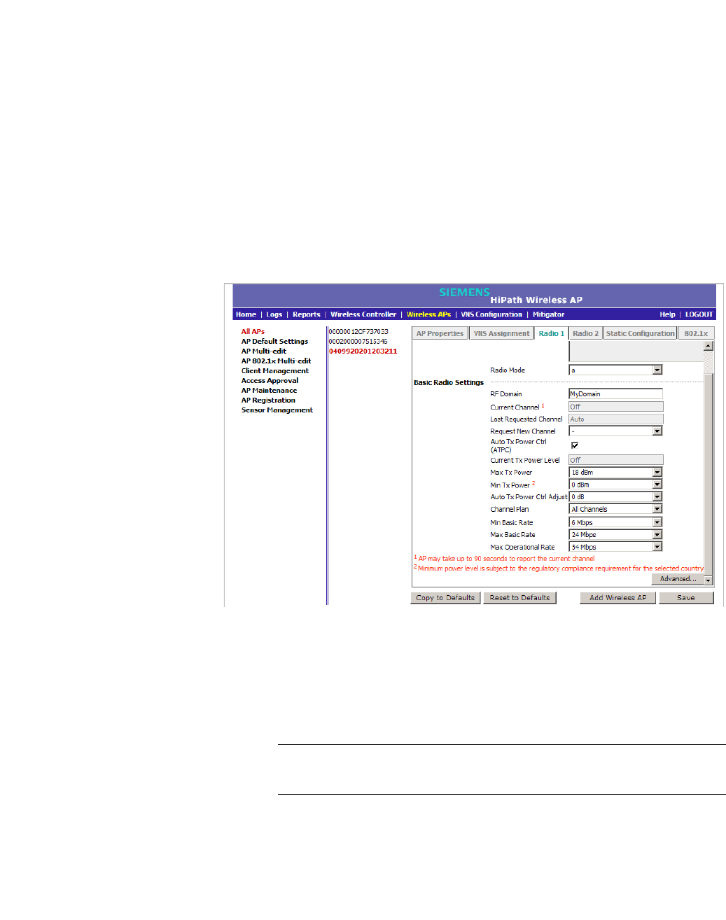
hwc_apstartup.fm
Configuring the Wireless AP
Configuring Wireless AP settings
9034530-02, March 2010
HiPath Wireless Controller, Access Points and Convergence Software V7.11, User Guide 153
•C20N – Up to 8 VNSs
•CRBT8210 – Up to 16 VNSs
•CRBT8110 – Up to 8 VNSs
The Wireless AP radios can be assigned to each of the configured VNSs in a
system. Each radio can be the subject of 8 VNS assignments (corresponding
to the number of SSIDs it can support). Once a radio has all 8 slots assigned,
it is no longer eligible for further assignment.
The BSS Info section is view only. After VNS configuration, the Basic
Service Set (BSS) section displays the MAC address on the Wireless AP for
each VNS and the SSIDs of the VNSs to which this radio has been assigned.
4. If applicable, click the Radio 1 tab.
5. In the Base Settings section, do the following:
• Radio Mode – Click one of the following radio options:
•off – Click to disable Radio 1.
•a – Click to enable 802.11a mode of Radio 1.
Note: The Wireless AP hardware version dictates the available radio
modes.
6. In the Basic Radio Settings section, do the following:

Configuring the Wireless AP
hwc_apstartup.fm
Configuring Wireless AP settings
9034530-02, March 2010
154 HiPath Wireless Controller, Access Points and Convergence Software V7.11, User Guide
•RF Domain – Type a string that uniquely identifies a group of APs that
cooperate in managing RF channels and transmission power levels. The
maximum length of the string is 16 characters. The RF Domain is used to
identify a group of Wireless APs.
• Request New Channel – Click the wireless channel you want the
Wireless AP to use to communicate with wireless devices.
Click Auto to request the ACS to search for a new channel for the
Wireless AP, using a channel selection algorithm. This forces the
Wireless AP to go through the auto-channel selection process again.
Depending on the regulatory domain (based on country), some channels
may be restricted. The default value is based on North America. For more
information, see Appendix B.
• Auto Tx Power Ctrl (ATPC) – Select to enable ATPC. ATPC
automatically adapts transmission power signals according to the
coverage provided by the Wireless APs. After a period of time, the system
will stabilize itself based on the RF coverage of your Wireless APs.
Note: If you disable ATPC, you can elect to maintain using the current Tx
power setting ATPC had established. If you elect to maintain using the
ATPC power setting, the displayed Current Tx Power Level value
becomes the new Max Tx Power value for the Wireless AP.
•Max Tx Power – Click the maximum Tx power level to which the range of
transmit power can be adjusted: 0 to 23 dBm. It is recommended to use
23 dBm to not limit the potential Tx power level range that can be used.
•Min Tx Power – If ATPC is enabled, click the minimum Tx power level to
which the range of transmit power can be adjusted. It is recommended to
use the lowest value available to not limit the potential Tx power level
range that can be used.
Note: The Minimum Tx Power level is subject to the regulatory
compliance requirement for the selected country.
• Auto Tx Power Ctrl Adjust – If ATPC is enabled, click the Tx power level
that can be used to adjust the ATPC power levels that the system has
assigned. It is recommended to use 0 dB during your initial configuration.
If you have an RF plan that recommends Tx power levels for each
Wireless AP, compare the actual Tx power levels your system has

hwc_apstartup.fm
Configuring the Wireless AP
Configuring Wireless AP settings
9034530-02, March 2010
HiPath Wireless Controller, Access Points and Convergence Software V7.11, User Guide 155
assigned against the recommended values your RF plan has provided.
Use the Auto Tx Power Ctrl Adjust value to achieve the recommended
values.
Note:
• Current Channel – This field is view only. It displays the actual channel the
ACS has assigned to the Wireless AP radio. The Current Channel value and
the Last Requested Channel value may be different because the ACS
automatically assigns the best available channel to the Wireless AP, ensuring
that a Wireless AP’s radio is always operating on the best available channel.
• Last Requested Channel – This field is view only. This field displays the
last wireless channel that you had selected for the Wireless AP to
communicate with the wireless devices.
• Current Tx Power Level – This field is view only. It displays the actual Tx
power level assigned to the Wireless AP radio.
• Channel Plan – If ACS is enabled, you can define a channel plan for the
Wireless AP. Defining a channel plan allows you to limit which channels
are available for use during an ACS scan. For example, you may want to
avoid using specific channels because of low power, regulatory domain,
or radar interference. Click one of the following:
• All channels – ACS scans all channels for an operating channel and
returns both DFS and non-DFS channels, if available.
• All Non-DFS Channels – ACS scans all non-DFS channels for an
operating channel. This selection is available when there is at least
one DFS channel supported for the selected country.
•Custom – To configure individual channels from which the ACS will
select an operating channel, click Configure. The Custom Channel
Plan dialog displays. By default, all channels participate in the
channel plan. Click the individual channels you want to include in the
channel plan. To select contiguous channels, use the Shift key. To
select multiple, non-contiguous channels in the list, use the CTRL
key. Click OK to save the configuration.

Configuring the Wireless AP
hwc_apstartup.fm
Configuring Wireless AP settings
9034530-02, March 2010
156 HiPath Wireless Controller, Access Points and Convergence Software V7.11, User Guide
• Min Basic Rate – Click the minimum data rate that must be supported by
all stations in a BSS: 6, 12, or 24 Mbps. If necessary, the Max Basic Rate
choices adjust automatically to be higher or equal to the Min Basic Rate.
• Max Basic Rate – Click the maximum data rate that must be supported
by all stations in a BSS: 6, 12, or 24 Mbps. If necessary, the Max Basic
Rate choices adjust automatically to be higher or equal to the Min Basic
Rate.
• Max Operational Rate – Click the maximum data rate that clients can
operate at while associated with the Wireless AP: 24, 36, 48, or 54 Mbps.
If necessary, the Max Operational Rate choices adjust automatically to
be higher or equal to the Max Basic Rate.
7. To modify Radio 1 advanced settings, click Advanced. The Advanced
dialog is displayed.
8. In the Advanced dialog Base Settings section, do the following:
• DTIM Period – Type the desired DTIM (Delivery Traffic Indication
Message) period — the number of beacon intervals between two DTIM
beacons. To ensure the best client power savings, use a large number.
For example, 5. Use a small number to minimize broadcast and multicast
delay. The default value is 5.
• Beacon Period – Type the desired time, in milliseconds, between
beacon transmissions. The default value is 100 milliseconds.
• RTS/CTS Threshold – Type the packet size threshold, in bytes, above
which the packet will be preceded by an RTS/CTS (Request to
Send/Clear to Send) handshake. The default value is 2346, which means
all packets are sent without RTS/CTS. Reduce this value only if
necessary.
• Frag. Threshold – Type the fragment size threshold, in bytes, above
which the packets will be fragmented by the Wireless AP prior to
transmission. The default value is 2346, which means all packets are sent
unfragmented. Reduce this value only if necessary.

hwc_apstartup.fm
Configuring the Wireless AP
Configuring Wireless AP settings
9034530-02, March 2010
HiPath Wireless Controller, Access Points and Convergence Software V7.11, User Guide 157
• Max % of non-unicast traffic per Beacon period – Enter the maximum
percentage of time that the AP will transmit non-unicast packets
(broadcast and multicast traffic) for each configured Beacon Period. For
each non-unicast packet transmitted, the system calculates the airtime
used by eack packet and drops all packets that exceed the configured
maximum percentage. By restricting non-unicast traffic, you limit the
impact of broadcasts and multicasts on overall system performance.
• Maximum Distance – Enter a value from 100 to 15,000 meters that
identifies the maximum link distance between APs that participate in a
WDS. This value ensures that the acknowledgement of communication
between APs does not exceed the timeout value predefined by the 802.11
standard. The default value is 100 meters. If the link distance between
APs is greater than 100 meters, configure the maximum distance up to
15,000 meters so that the software increases the timeout value
proportionally with the distance between APs.
Do not change the default setting for the radio that provides service to
802.11 clients only.
9. In the Advanced dialog Basic Radio Settings section, do the following:
• Dynamic Channel Selection – To enable Dynamic Channel Selection,
click one of the following:
• Monitor Mode – If traffic or noise levels exceed the configured DCS
thresholds, an alarm is triggered and an information log is generated.
• Active Mode – If traffic or noise levels exceed the configured DCS
thresholds, an alarm is triggered and an information log is generated.
In addition, the Wireless AP will cease operating on the current
channel and ACS is employed to automatically select an alternate
channel for the Wireless AP to operate on.
• DCS Noise Threshold – Type the noise interference level, measured
in dBm, after which ACS will scan for a new operating channel for the
Wireless AP if the threshold is exceeded.
• DCS Channel Occupancy Threshold – Type the channel utilization
level, measured as a percentage, after which ACS will scan for a new
operating channel for the Wireless AP if the threshold is exceeded.
• DCS Update Period – Type the time, measured in minutes that
determines the period during which the Wireless AP averages the
DCS Noise Threshold and DCS Channel Occupancy Threshold
measurements. If either one of these thresholds is exceeded, then
the Wireless AP will trigger ACS.

Configuring the Wireless AP
hwc_apstartup.fm
Configuring Wireless AP settings
9034530-02, March 2010
158 HiPath Wireless Controller, Access Points and Convergence Software V7.11, User Guide
•Rx Diversity – Click Best for the best signal from both antennas, or Left
or Right to choose either of the two diversity antennas. The default and
recommended selection is Best. If only one antennae is connected, use
the corresponding Left or Right diversity setting. Do not use Best if two
identical antennas are not used.
• Tx Diversity – Click Alternate for the best signal from both antennas, or
Left or Right to choose either of the two diversity antennas. The default
selection is Alternate that maximizes performance for most clients.
However, some clients may behave oddly with Tx Diversity set to
Alternate. Under those circumstances, it is recommended to use either
Left or Right for Tx Diversity. If only one antennae is connected, use the
corresponding Left or Right diversity setting. Do not use Alternate if two
identical antennas are not used.
• Total # of Retries for Background BK – Click the number of retries for
the Background transmission queue. The default value is adaptive
(multi-rate). The recommended setting is adaptive (multi-rate).
• Total # of Retries for Best Effort BE – Click the number of retries for the
Best Effort transmission queue. The default value is adaptive (multi-
rate). The recommended setting is adaptive (multi-rate).
• Total # of Retries for Video VI – Click the number of retries for the Video
transmission queue. The default value is adaptive (multi-rate). The
recommended setting is adaptive (multi-rate).
• Total # of Retries for Voice VO – Click the number of retries for the
Voice transmission queue. The default value is adaptive (multi-rate).
The recommended setting is adaptive (multi-rate).
• Total # of Retries for Turbo Voice TVO – Click the number of retries for
the Turbo Voice transmission queue. The default value is adaptive
(multi-rate). The recommended setting is adaptive (multi-rate).
10. Click Close. The Advanced dialog is closed.
11. If applicable, click the Radio 2 tab.
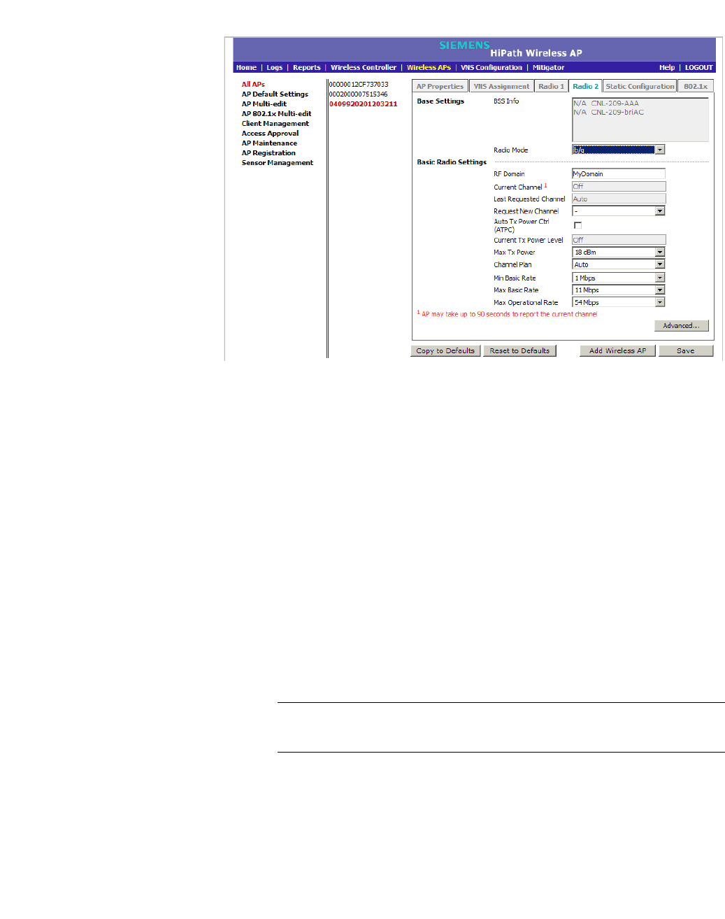
hwc_apstartup.fm
Configuring the Wireless AP
Configuring Wireless AP settings
9034530-02, March 2010
HiPath Wireless Controller, Access Points and Convergence Software V7.11, User Guide 159
12. In the Base Settings section, do the following:
• Radio Mode – Click one of the following radio options:
•off – Click to disable Radio 2.
•b – Click to enable the 802.11b-only mode of Radio 2. If selected, the
AP will use only 11b (CCK) rates with all associated clients.
•g – Click to select the 802.11g-only mode of Radio 2. If selected, the
AP will not accept associations from 11b clients, but it will still use all
CCK and OFDM 11g rates with its associated clients. To disable CCK
rates, use the Min/Max Basic Rate and Max Operation Rate
controls to select OFDM-only rates.
•b/g – Click to enable both the 802.11g mode and the 802.11b mode
of Radio 2. If selected, the AP will use 11b (CCK) and 11g-specific
(OFDM) rates with all of the associated clients. The AP will not
transmit or receive 11n rates.
Note: Depending on the radio modes you select, some of the radio
settings may not be available for configuration.
13. In the Basic Radio Settings section, do the following:
•RF Domain – Type a string that uniquely identifies a group of APs that
cooperate in managing RF channels and transmission power levels. The
maximum length of the string is 16 characters. The RF Domain is used to
identify a group of Wireless APs.

Configuring the Wireless AP
hwc_apstartup.fm
Configuring Wireless AP settings
9034530-02, March 2010
160 HiPath Wireless Controller, Access Points and Convergence Software V7.11, User Guide
• Request New Channel – Click the wireless channel you want the
Wireless AP to use to communicate with wireless devices.
Click Auto to request the ACS to search for a new channel for the
Wireless AP, using a channel selection algorithm. This forces the
Wireless AP to go through the auto-channel selection process again.
Depending on the regulatory domain (based on country), some channels
may be restricted. The default value is based on North America. For more
information, see Appendix B.
• Auto Tx Power Ctrl (ATPC) – Select to enable ATPC. ATPC
automatically adapts transmission power signals according to the
coverage provided by the Wireless APs. After a period of time, the system
will stabilize itself based on the RF coverage of your Wireless APs.
Note: If you disable ATPC, you can elect to maintain using the current Tx
power setting ATPC had established. If you elect to maintain using the
ATPC power setting, the displayed Current Tx Power Level value
becomes the new Max Tx Power value for the Wireless AP.
•Max Tx Power – Click the maximum Tx power level to which the range of
transmit power can be adjusted: 8 to 18 dBm. It is recommended to use
18 dBm to not limit the potential Tx power level range that can be used.
•Min Tx Power – If ATPC is enabled, click the minimum Tx power level to
which the range of transmit power can be adjusted. It is recommended to
use the lowest value available to not limit the potential Tx power level
range that can be used.
Note: The Minimum Tx Power level is subject to the regulatory
compliance requirement for the selected country.
• Auto Tx Power Ctrl Adjust – If ATPC is enabled, click the Tx power level
that can be used to adjust the ATPC power levels that the system has
assigned. It is recommended to use 0 dB during your initial configuration.
If you have an RF plan that recommends Tx power levels for each
Wireless AP, compare the actual Tx power levels your system has
assigned against the recommended values your RF plan has provided.
Use the Auto Tx Power Ctrl Adjust value to achieve the recommended
values.
Note:
• Current Channel – This field is view only. It displays the actual channel the
ACS has assigned to the Wireless AP radio. The Current Channel value and
the Last Requested Channel value may be different because the ACS
automatically assigns the best available channel to the Wireless AP, ensuring
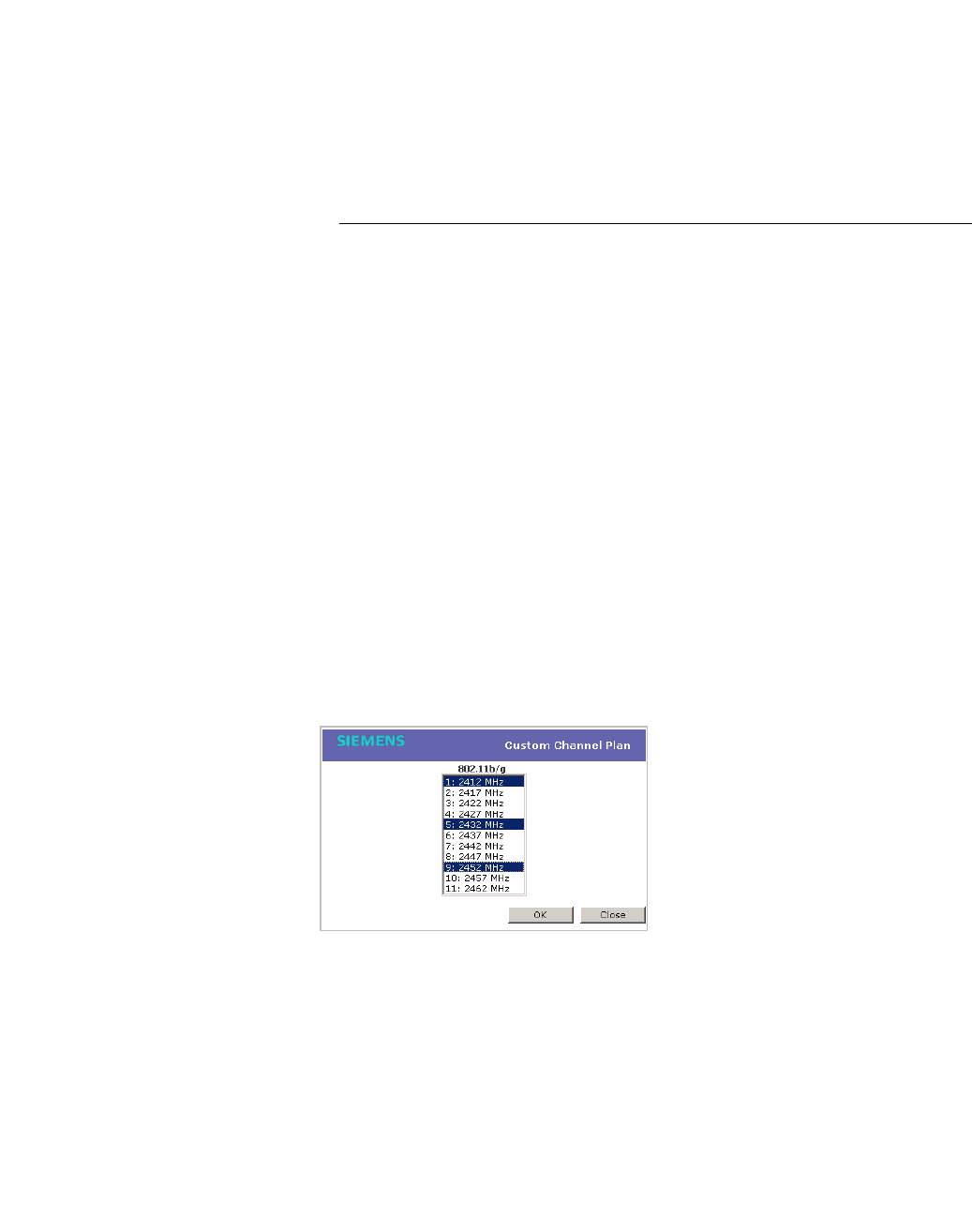
hwc_apstartup.fm
Configuring the Wireless AP
Configuring Wireless AP settings
9034530-02, March 2010
HiPath Wireless Controller, Access Points and Convergence Software V7.11, User Guide 161
that a Wireless AP’s radio is always operating on the best available channel.
• Last Requested Channel – This field is view only. This field displays the
last wireless channel that you had selected for the Wireless AP to
communicate with the wireless devices.
• Current Tx Power Level – This field is view only. It displays the actual Tx
power level assigned to the Wireless AP radio.
• Channel Plan – If ACS is enabled, you can define a channel plan for the
Wireless AP. Defining a channel plan allows you to limit which channels
are available for use during an ACS scan. For example, you may want to
avoid using specific channels because of low power, regulatory domain,
or radar interference. Click one of the following:
• 3 Channel Plan – ACS will scan the following channels: 1, 6, and 11
in the US, and 1, 7, and 13 in Europe.
• 4 Channel Plan – ACS will scan the following channels: 1, 4, 7, and
11 in the US, and 1, 5, 9, and 13 in Europe.
•Auto – ACS will scan the default channel plan channels: 1, 6, and 11
in the US, and 1, 5, 9, and 13 in Europe.
•Custom – If you want to configure individual channels from which the
ACS will select an operating channel, click Configure. The Add
Channels dialog is displayed. Click the individual channels you want
to add to the channel plan while pressing the CTRL key, and then click
OK.
• Min Basic Rate – Click the minimum data rate that must be supported by
all stations in a BSS: 1, 2, 5.5, or 11 Mbps. If necessary, the Max Basic
Rate choices adjust automatically to be higher or equal to the Min Basic
Rate.
• Max Basic Rate – Click the maximum data rate that must be supported
by all stations in a BSS: 1, 2, 5.5, or 11 Mbps. If necessary, the Max Basic
Rate choices adjust automatically to be higher or equal to the Min Basic
Rate.

Configuring the Wireless AP
hwc_apstartup.fm
Configuring Wireless AP settings
9034530-02, March 2010
162 HiPath Wireless Controller, Access Points and Convergence Software V7.11, User Guide
• Max Operational Rate – Click the maximum data rate that clients can
operate at while associated with the Wireless AP: 11, 12, 18, 24, 36, 48,
or 54 Mbps. If necessary, the Max Operational Rate choices adjust
automatically to be higher or equal to the Max Basic Rate.
14. To modify Radio 2 advanced settings, click Advanced. The Advanced
dialog is displayed.
15. In the Advanced dialog Base Settings section, do the following:
• DTIM Period – Type the desired DTIM (Delivery Traffic Indication
Message) period — the number of beacon intervals between two DTIM
beacons. To ensure the best client power savings, use a large number.
For example, 5. Use a small number to minimize broadcast and multicast
delay. The default value is 5.
• Beacon Period – Type the desired time, in milliseconds, between
beacon transmissions. The default value is 100 milliseconds.
• RTS/CTS Threshold – Type the packet size threshold, in bytes, above
which the packet will be preceded by an RTS/CTS (Request to
Send/Clear to Send) handshake. The default value is 2346, which means
all packets are sent without RTS/CTS. Reduce this value only if
necessary.
• Frag. Threshold – Type the fragment size threshold, in bytes, above
which the packets will be fragmented by the Wireless AP prior to
transmission. The default value is 2346, which means all packets are sent
unfragmented. Reduce this value only if necessary.
• Max % of non-unicast traffic per Beacon period – Enter the maximum
percentage of time that the AP will transmit non-unicast packets
(broadcast and multicast traffic) for each configured Beacon Period. For
each non-unicast packet transmitted, the system calculates the airtime
used by eack packet and drops all packets that exceed the configured
maximum percentage. By restricting non-unicast traffic, you limit the
impact of broadcasts and multicasts on overall system performance.
• Maximum Distance – Enter a value from 100 to 15,000 meters that
identifies the maximum link distance between APs that participate in a
WDS. This value ensures that the acknowledgement of communication
between APs does not exceed the timeout value predefined by the 802.11
standard. The default value is 100 meters. If the link distance between
APs is greater than 100 meters, configure the maximum distance up to
15,000 meters so that the software increases the timeout value
proportionally with the distance between APs.
Do not change the default setting for the radio that provides service to
802.11 clients only.
16. In the Advanced dialog Basic Radio Settings section, do the following:

hwc_apstartup.fm
Configuring the Wireless AP
Configuring Wireless AP settings
9034530-02, March 2010
HiPath Wireless Controller, Access Points and Convergence Software V7.11, User Guide 163
• Dynamic Channel Selection – To enable Dynamic Channel Selection,
click one of the following:
• Monitor Mode – If traffic or noise levels exceed the configured DCS
thresholds, an alarm is triggered and an information log is generated.
• Active Mode – If traffic or noise levels exceed the configured DCS
thresholds, an alarm is triggered and an information log is generated.
In addition, the Wireless AP will cease operating on the current
channel and ACS is employed to automatically select an alternate
channel for the Wireless AP to operate on.
• DCS Noise Threshold – Type the noise interference level, measured
in dBm, after which ACS will scan for a new operating channel for the
Wireless AP if the threshold is exceeded.
• DCS Channel Occupancy Threshold – Type the channel utilization
level, measured as a percentage, after which ACS will scan for a new
operating channel for the Wireless AP if the threshold is exceeded.
• DCS Update Period – Type the time, measured in minutes that
determines the period during which the Wireless AP averages the
DCS Noise Threshold and DCS Channel Occupancy Threshold
measurements. If either one of these thresholds is exceeded, then
the Wireless AP will trigger ACS.
• Rx Diversity – Click Best for the best signal from both antennas, or Left
or Right to choose either of the two diversity antennas. The default and
recommended selection is Best. If only one antennae is connected, use
the corresponding Left or Right diversity setting. Do not use Best if two
identical antennas are not used.
• Tx Diversity – Click Alternate for the best signal from both antennas, or
Left or Right to choose either of the two diversity antennas. The default
selection is Alternate that maximizes performance for most clients.
However, some clients may behave oddly with Tx Diversity set to
Alternate. Under those circumstances, it is recommended to use either
Left or Right for Tx Diversity. If only one antennae is connected, use the
corresponding Left or Right diversity setting. Do not use Alternate if two
identical antennas are not used.
• Total # of Retries for Background BK – Click the number of retries for
the Background transmission queue. The default value is adaptive
(multi-rate). The recommended setting is adaptive (multi-rate).
• Total # of Retries for Best Effort BE – Click the number of retries for the
Best Effort transmission queue. The default value is adaptive (multi-
rate). The recommended setting is adaptive (multi-rate).
• Total # of Retries for Video VI – Click the number of retries for the Video
transmission queue. The default value is adaptive (multi-rate). The
recommended setting is adaptive (multi-rate).

Configuring the Wireless AP
hwc_apstartup.fm
Configuring Wireless AP settings
9034530-02, March 2010
164 HiPath Wireless Controller, Access Points and Convergence Software V7.11, User Guide
• Total # of Retries for Voice VO – Click the number of retries for the
Voice transmission queue. The default value is adaptive (multi-rate).
The recommended setting is adaptive (multi-rate).
• Total # of Retries for Turbo Voice TVO – Click the number of retries for
the Turbo Voice transmission queue. The default value is adaptive
(multi-rate). The recommended setting is adaptive (multi-rate).
17. In the Advanced dialog 11b Settings section, do the following:
•Preamble – Click a preamble type for 11b-specific (CCK) rates: Short or
Long. Click Short if you are sure that there is no pre-11b AP or a client
in the vicinity of this AP. Click Long if compatibility with pre-11b clients is
required.
18. In the Advanced dialog 11g Settings section, do the following:
• Protection Mode – Click a protection mode: None, Auto, or Always.
The default and recommended setting is Auto. Click None if 11b APs and
clients are not expected. Click Always if you expect many 11b-only
clients.
• Protection Rate – Click a protection rate: 1, 2, 5.5, or 11 Mbps. The
default and recommended setting is 11. Only reduce the rate if there are
many 11b clients in the environment or if the deployment has areas with
poor coverage. For example, rates lower than 11 Mbps are required to
ensure coverage.
• Protection Type – Click a protection type: CTS Only or RTS CTS. The
default and recommended setting is CTS Only. Click RTS CTS only if an
11b AP that operates on the same channel is detected in the
neighborhood, or if there are many 11b-only clients in the environment.
Note: The overall throughput is reduced when Protection Mode is enabled,
due to the additional overhead caused by the RTS/CTS. The overhead is
minimized by setting Protection Type to CTS Only and Protection Rate to
11 Mbps. The overhead causes the overall throughput to be sometimes lower
than if just 11b mode is used. If there are many 11b clients, it is recommended
to disable 11g support (11g clients are backward compatible with 11b APs).
An alternate approach, although a more expensive method, is to dedicate all
APs on a channel for 11b (for example, disable 11g on these APs) and disable
11b on all other APs. The difficulty with this method is that the number of APs
must be increased to ensure coverage separately for 11b and 11g clients.
19. Click Close. The Advanced dialog is closed.
20. To save your changes, click Save.
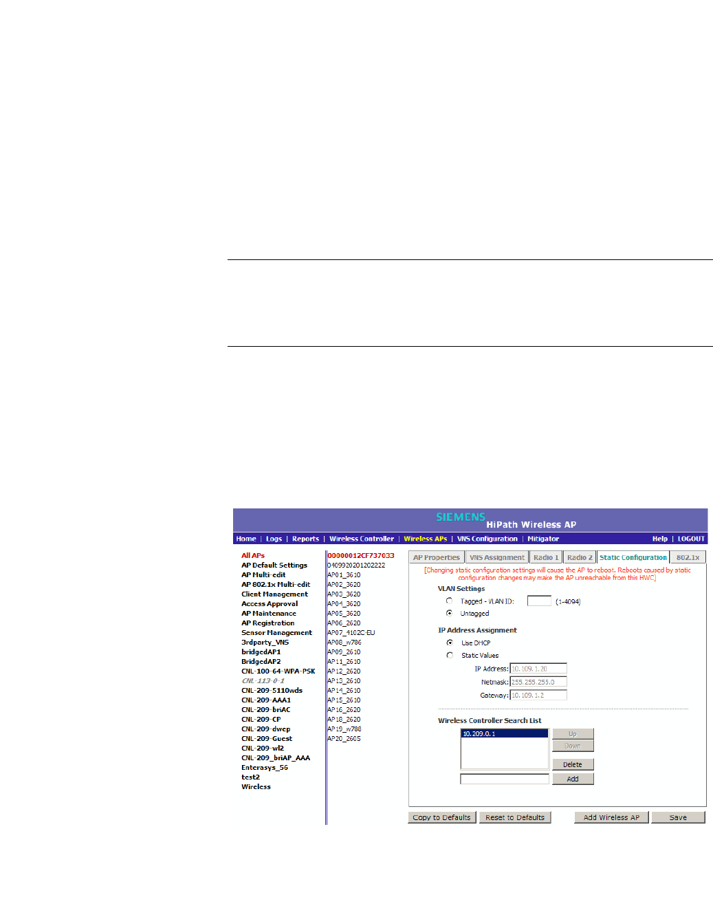
hwc_apstartup.fm
Configuring the Wireless AP
Configuring Wireless AP settings
9034530-02, March 2010
HiPath Wireless Controller, Access Points and Convergence Software V7.11, User Guide 165
4.4.6 Setting up the Wireless AP using static
configuration
The Wireless AP static configuration feature provides the HiPath Wireless
Controller, Access Points and Convergence Software solution with the capability
for a network with either a central office or a branch office model. The static
configuration settings assist in the setup of branch office support. These settings
are not dependent of branch topology, but instead can be employed at any time
if required. In the branch office model, Wireless APs are installed in remote sites,
while the HiPath Wireless Controller is in a central office. The Wireless APs
require the capability to interact in both the local site network and the central
network. To achieve this model, a static configuration is used.
Note: If a Wireless AP with a statically configured IP address (without a statically
configured Wireless Controller Search List) cannot register with the HiPath
Wireless Controller within the specified number of retries, the Wireless AP will
use SLP, DNS, and SLP multicast as a backup mechanism.
To set up a Wireless AP using static configuration:
1. From the main menu, click Wireless AP Configuration. The HiPath
Wireless AP screen is displayed.
2. Click the appropriate Wireless AP in the list.
3. Click the Static Configuration tab.
4. Select one of the VLAN settings for the Wireless AP:

Configuring the Wireless AP
hwc_apstartup.fm
Configuring Wireless AP settings
9034530-02, March 2010
166 HiPath Wireless Controller, Access Points and Convergence Software V7.11, User Guide
• Tagged - VLAN ID – Select if you want to assign this AP to a specific
VLAN and type the value in the box.
• Untagged – Select if you want this AP to be untagged. This option is
selected by default.
Caution: Caution should be exercised when using this feature. For more
information, see Section 4.5, “Configuring VLAN tags for Wireless APs”,
on page 169.
If the Wireless AP VLAN is not configured properly (wrong tag),
connecting to the Wireless AP may not be possible. To recover from this
situation, you will need to reset the Wireless AP to its factory default
settings. For more information, see the HiPath Wireless Controller,
Access Points and Convergence Software Maintenance Guide.
5. Select one of the two methods of IP address assignment for the Wireless AP:
• Use DHCP – Select this option to enable Dynamic Host Configuration
Protocol (DHCP). This option is enabled by default.
• Static Values – Select this option to specify the IP address of the
Wireless AP.
•IP Address – Type the IP address of the AP.
• Subnet Mask – Type the appropriate subnet mask to separate the
network portion from the host portion of the address.
• Gateway – Type the default gateway of the network.
Note: For the initial configuration of a Wireless AP to use a static IP
address assignment, the following is recommended:
• Allow the Wireless AP to first obtain an IP address using DHCP. By
default, Wireless APs are configured to use the DHCP IP address
configuration method.
• Allow the Wireless AP to connect to the HiPath Wireless Controller using
the DHCP assigned IP address.
• After the Wireless AP has successfully registered to the HiPath Wireless
Controller, use the Static Configuration tab to configure a static IP
address for the Wireless AP, and then save the configuration.
• Once the static IP address has been configured on the Wireless AP, the
Wireless AP can then be moved to its target location, if applicable. (A
branch office scenario is an example of a setup that may require static IP
assignment.)
6. In the Add box, type the IP address of the HiPath Wireless Controller that will
control this Wireless AP.

hwc_apstartup.fm
Configuring the Wireless AP
Configuring Wireless AP settings
9034530-02, March 2010
HiPath Wireless Controller, Access Points and Convergence Software V7.11, User Guide 167
7. Click Add. The IP address is added to the list.
8. Repeat steps 5 and 6 to add additional HiPath Wireless Controllers.
9. Click Up and Down to modify the order of the HiPath Wireless Controllers.
The maximum is three controllers.
The Wireless AP attempts to connect to the IP addresses in the order in which
they are listed. The Wireless AP is successful when it finds a HiPath Wireless
Controller that will allow it to register.
This feature allows the Wireless AP to bypass the discovery process. If the
Wireless Controller Search List box is not populated, the Wireless AP will
use SLP to discover a HiPath Wireless Controller.
For the initial Wireless AP deployment, it is necessary to use one of the
described options in Section 4.2, “Discovery and registration overview”, on
page 97.
10. To save your changes, click Save.
4.4.7 Configuring Telnet/SSH Access
If you are configuring a static IP address either for the Wireless AP or Outdoor
Wireless AP, you must ensure that Telnet Access is Enabled on the Wireless
AP Configuration screen.
Note: The new telnet access password that you set up over the controller’s user
interface overrides the default telnet access password.
To enable or disable telnet access:
1. From the main menu, click Wireless AP Configuration. The Wireless AP
Configuration screen is displayed.
2. In the Wireless AP list, click the Wireless AP for which you want to enable or
disable telnet.
3. Click Advanced. The Advanced dialog is displayed.
4. In the Telnet Access drop-down list, click one of the following:
• Enable – Enables telnet access
• Disable – Disables telnet access
Note: The option to enable or disable Telnet Access will only be displayed
if the Wireless AP is a Standard Wireless AP or Outdoor AP. For 11n Wireless
APs, SSH is always enabled by default.
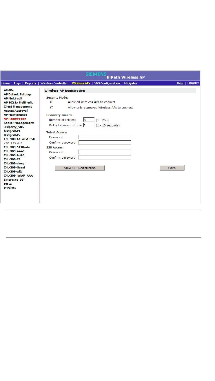
Configuring the Wireless AP
hwc_apstartup.fm
Configuring Wireless AP settings
9034530-02, March 2010
168 HiPath Wireless Controller, Access Points and Convergence Software V7.11, User Guide
5. To save your changes, click Save.
To set up a new telnet/SSH access password:
1. From the main menu, click Wireless AP Configuration. The Wireless AP
Configuration screen is displayed.
2. In the left pane, click AP Registration. The Wireless AP Registration
screen is displayed.
Note: The SSH Access section on the AP Registration screen is applicable
to the 11n Wireless APs. The Telnet Acces section is applicable to the
Standard Wireless AP or the HiPath Wireless Outdoor AP.
3. If you are setting up a new telnet access password for either the Wireless AP
or Wireless Outdoor AP, type the new password in the Password box under
the Telnet Access section. If you are setting up a new SSH access password
for the Wireless 802.11n AP, type the new password in the Password box
under the SSH Access section.
4. In the Confirm Password box, re-type the password.
5. To save your changes, click Save.

hwc_apstartup.fm
Configuring the Wireless AP
Configuring VLAN tags for Wireless APs
9034530-02, March 2010
HiPath Wireless Controller, Access Points and Convergence Software V7.11, User Guide 169
4.5 Configuring VLAN tags for Wireless APs
Caution: You must exercise caution while configuring a VLAN ID tag. If a VLAN
tag is not configured properly, the connectivity between the HiPath Wireless
Controller and the Wireless AP will be lost.
To configure the VLAN tag for the Wireless AP, you must connect the Wireless
AP to a point on the central office network that does not require VLAN tagging. If
the VLAN tagging is configured correctly and you are still on the central office
network, the Wireless AP will lose connection with the HiPath Wireless Controller
after it is rebooted (the Wireless AP reboots when the configuration settings are
saved).
If the Wireless AP does not lose its connection with the HiPath Wireless
Controller after the reboot, the VLAN ID has not been configured correctly. After
the VLAN is configured correctly, you can move the Wireless AP to the target
location.
To configure Wireless APs with a VLAN tag:
1. Connect the Wireless AP in the central office to the HiPath Wireless
Controller port (or to a network point) that does not require VLAN tagging.
2. From the main menu, click Wireless AP Configuration. The Wireless AP
Configuration screen is displayed.
3. Click the Static Configuration tab.
4. In the VLAN Settings section, select Tagged - VLAN ID.
5. In the Tagged - VLAN ID text box, type the VLAN ID on which the Wireless
AP will operate.
6. To save your changes, click Save. The Wireless AP reboots and loses
connection with the HiPath Wireless Controller.
7. Log out from the HiPath Wireless Controller.
8. Disconnect the Wireless AP from the central office network and move it to the
target location.
9. Power up the Wireless AP. The Wireless AP connects to the HiPath Wireless
Controller.
If the Wireless AP does not connect to the HiPath Wireless Controller, the
Wireless AP was not configured properly. To recover from this situation, you
must reset the Wireless AP to its factory default settings, and reconfigure the
static IP address. For more information, see the HiPath Wireless Controller,
Access Points and Convergence Software User Guide.

Configuring the Wireless AP
hwc_apstartup.fm
Configuring VLAN tags for Wireless APs
9034530-02, March 2010
170 HiPath Wireless Controller, Access Points and Convergence Software V7.11, User Guide
4.5.1 Setting up 802.1x authentication for a Wireless
AP
802.1x is an authentication standard for wired and wireless LANs. The 802.1x
standard can be used to authenticate access points to the LAN to which they are
connected. 802.1x support provides security for network deployments where
access points are placed in public spaces.
To successfully set up 802.1x authentication of a Wireless AP, the Wireless AP
must be configured for 802.1x authentication before the Wireless AP is connected
to a 802.1x enabled switch port.
Caution: If the switch port, to which the Wireless AP is connected to, is not
802.1x enabled, the 802.1x authentication will not take effect.
802.1x authentication credentials can be updated at any time, whether or not the
Wireless AP is connected with an active session. If the Wireless AP is connected,
the new credentials are sent immediately. If the Wireless AP is not connected, the
new credentials are delivered the next time the Wireless AP connects to the
HiPath Wireless Controller.
There are two main aspects to the 802.1x feature:
•Credential management – The HiPath Wireless Controller and the Wireless
AP are responsible for the requesting, creating, deleting, or invalidating the
credentials used in the authentication process.
•Authentication – The Wireless AP is responsible for the actual execution of
the EAP-TLS or PEAP protocol.
802.1x authentication can be configured on a per access point basis. For
example, 802.1x authentication can be applied to specific Wireless APs
individually or with a multi-edit function.
The 802.1x authentication supports two authentication methods:
•PEAP (Protected Extensible Authentication Protocol)
•Is the recommended 802.1x authentication method
•Requires minimal configuration effort and provides equal authentication
protection to EAP-TLS
•Uses user ID and passwords for authentication of access points
•EAP-TLS
•Requires more configuration effort
•Requires the use of a third-party Certificate Authentication application

hwc_apstartup.fm
Configuring the Wireless AP
Configuring VLAN tags for Wireless APs
9034530-02, March 2010
HiPath Wireless Controller, Access Points and Convergence Software V7.11, User Guide 171
•Uses certificates for authentication of access points
•HiPath Wireless Controller can operate in either proxy mode or pass
through mode.
•Proxy mode – The HiPath Wireless Controller generates the public
and private key pair used in the certificate.
•Pass through mode – The certificate and private key is created by the
third-party Certificate Authentication application.
Note: Although a Wireless AP can support using both PEAP and EAP-TLS
credentials simultaneously, it is not recommended to do so. Instead, it is
recommended that only one type of authentication be used, and that only
credentials for that type of authentication be installed on the Wireless AP.
4.5.1.1 Configuring 802.1x PEAP authentication
PEAP authentication uses user ID and passwords for authentication. To
successfully configure 802.1x authentication of a Wireless AP, the Wireless AP
must first be configured for 802.1x authentication before the Wireless AP is
deployed on a 802.1x enabled switch port.
Note: User names and passwords for PEAP authentication credentials each
have a maximum length of 128 characters.
To configure 802.1x PEAP authentication:
1. From the main menu, click Wireless AP Configuration. The HiPath
Wireless AP screen is displayed.
2. In the Wireless AP list, click the Wireless AP for which you want to configure
802.1x PEAP authentication.
3. Click the 802.1x tab.
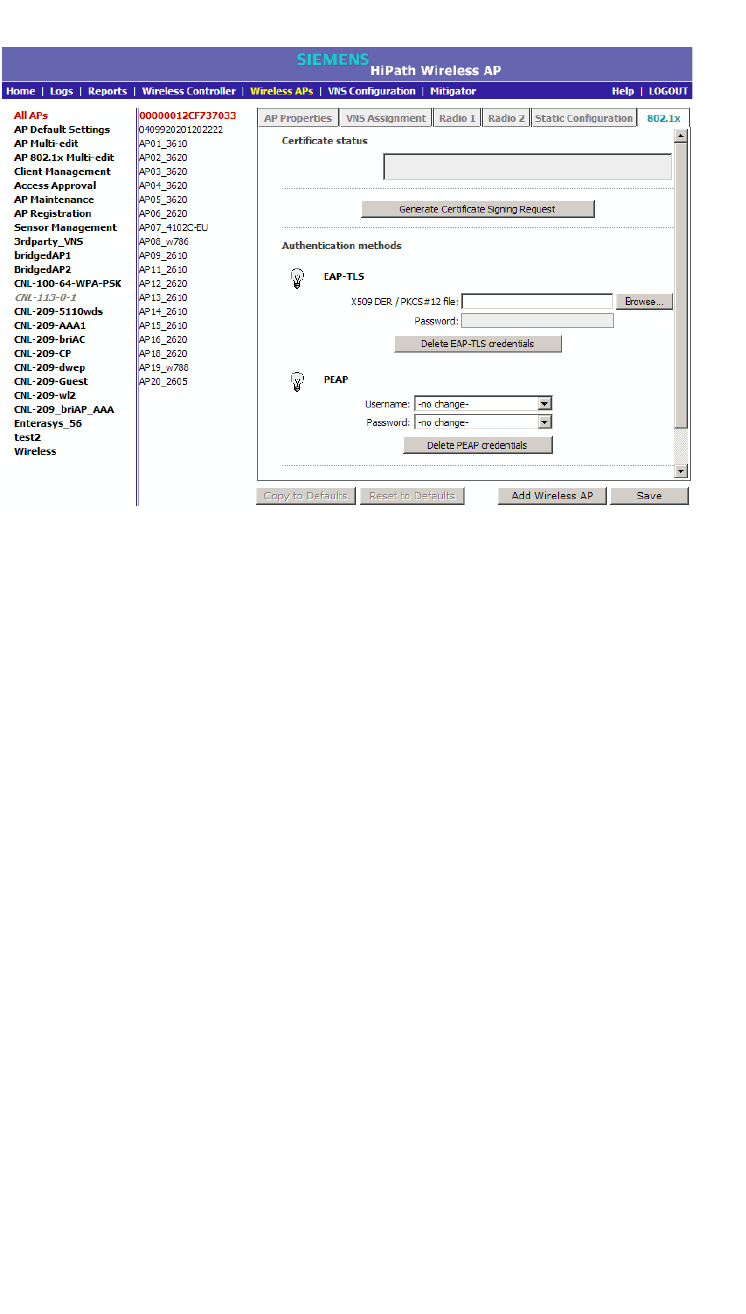
Configuring the Wireless AP
hwc_apstartup.fm
Configuring VLAN tags for Wireless APs
9034530-02, March 2010
172 HiPath Wireless Controller, Access Points and Convergence Software V7.11, User Guide
4. In the Username drop-down list, click the value you want to assign as the
user name credential:
•Name – The name of the Wireless AP, which is assigned on the AP
Properties tab. The Wireless AP name can be edited.
•Serial – The serial number of the Wireless AP. The Wireless AP serial
number cannot be edited.
•MAC – The MAC address of the Wireless AP. The Wireless AP MAC
address cannot be edited.
•Other – Click to specify a custom value. A text box is displayed. In the text
box, type the value you want to assign as the user name credential.
5. In the Password drop-down list, click the value you want to assign as the
password credential:
•Name – The name of the Wireless AP, which is assigned on the AP
Properties tab. The Wireless AP name can be edited.
•Serial – The serial number of the Wireless AP. The Wireless AP serial
number cannot be edited.
•MAC – The MAC address of the Wireless AP. The Wireless AP MAC
address cannot be edited.
•Other – Click to specify a custom value. A text box is displayed. In the text
box, type the value you want to assign as the password credential.
6. To save your changes, click Save.

hwc_apstartup.fm
Configuring the Wireless AP
Configuring VLAN tags for Wireless APs
9034530-02, March 2010
HiPath Wireless Controller, Access Points and Convergence Software V7.11, User Guide 173
The 802.1x PEAP authentication configuration is assigned to the Wireless
AP. The Wireless AP can now be deployed to a 802.1x enabled switch port.
4.5.1.2 Configuring 802.1x EAP-TLS authentication
EAP-TLS authentication uses certificates for authentication. A third-party
Certificate Authentication application is required to configure EAP-TLS
authentication. Certificates can be overwritten with new ones at any time.
With EAP-TLS authentication, the HiPath Wireless Controller can operate in
either proxy mode or pass through mode.
Note: When a Wireless AP configured with 802.1x EAP-TLS authentication is
connected to a HiPath Wireless Controller, the Wireless AP begins submitting
logs to the HiPath Wireless Controller 30 days before the certificate expires to
provide administrators with a warning of the impending expiry date.
Proxy mode
In proxy mode, HiPath Wireless Controller generates the public and private key
pair used in the certificate. You can specify the criteria used to create the
Certificate Request. The Certificate Request that is generated by the HiPath
Wireless Controller is then used by the third-party Certificate Authentication
application to create the certificate used for authentication of the Wireless AP. To
successfully configure 802.1x authentication of a Wireless AP, the Wireless AP
must first be configured for 802.1x authentication before the Wireless AP is
deployed on a 802.1x enabled switch port.
To configure 802.1x EAP-TLS authentication in proxy mode:
1. From the main menu, click Wireless AP Configuration. The HiPath
Wireless AP screen is displayed.
2. In the Wireless AP list, click the Wireless AP for which you want to configure
802.1x EAP-TLS authentication.
3. Click the 802.1x tab.
4. Click Generate certificate request. The Generate Certificate Request
window is displayed.

Configuring the Wireless AP
hwc_apstartup.fm
Configuring VLAN tags for Wireless APs
9034530-02, March 2010
174 HiPath Wireless Controller, Access Points and Convergence Software V7.11, User Guide
5. Type the criteria to be used to create the certificate request. All fields are
required:
• Country name – The two-letter ISO abbreviation of the name of the
country
• State or Province name – The name of the State/Province
• Locality name (city) – The name of the city
• Organization name – The name of the organization
• Organizational Unit name – The name of the unit within the organization
• Common name – Click the value you want to assign as the common
name of the Wireless AP:
•Name – The name of the Wireless AP, which is assigned on the AP
Properties tab. The Wireless AP name can be edited.
•Serial – The serial number of the Wireless AP. The Wireless AP serial
number cannot be edited.
•MAC – The MAC address of the Wireless AP. The Wireless AP MAC
address cannot be edited.
•Other – Click to specify a custom value. A text box is displayed. In the
text box, type the value you want to assign as the common name of
the Wireless AP.
• Email address – The email address of the organization
6. Click Generate certificate request. A certificate request file is generated
(.csr file extension). The name of the file is the Wireless AP serial number.
The File Download dialog is displayed.
7. Click Save. The Save as window is displayed.
8. Navigate to the location on your computer that you want to save the
generated certificate request file, and then click Save.

hwc_apstartup.fm
Configuring the Wireless AP
Configuring VLAN tags for Wireless APs
9034530-02, March 2010
HiPath Wireless Controller, Access Points and Convergence Software V7.11, User Guide 175
9. In the third-party Certificate Authentication application, use the content of the
generated certificate request file to generate the certificate file (.cer file
extension).
10. On the 802.1x tab, click Browse. The Choose file window is displayed.
11. Navigate to the location of the certificate file, and click Open. The name of the
certificate file is displayed in the X509 DER / PKCS#12 file box.
12. To save your changes, click Save.
The 802.1x EAP-TLS (certificate and private key) authentication in proxy
mode is assigned to the Wireless AP. The Wireless AP can now be deployed
to a 802.1x enabled switch port.
Pass through mode
In pass through mode, the certificate and private key is created by the third-party
Certificate Authentication application. To successfully configure 802.1x
authentication of a Wireless AP, the Wireless AP must first be configured for
802.1x authentication before the Wireless AP is deployed on a 802.1x enabled
switch port.
Before you configure 802.1x using EAP-TLS authentication in pass through
mode, you must first create a certificate using the third-party Certificate
Authentication application and save the certificate file in PKCS #12 file format
(.pfx file extension) on your system.
To configure 802.1x EAP-TLS authentication in pass through mode:
1. From the main menu, click Wireless AP Configuration. The HiPath
Wireless AP screen is displayed.
2. In the Wireless AP list, click the Wireless AP for which you want to configure
802.1x EAP-TLS authentication.
3. Click the 802.1x tab.
4. Click Browse. The Choose file window is displayed.
5. Navigate to the location of the certificate file (.pfx) and click Open. The name
of the certificate file is displayed in the X509 DER / PKCS#12 file box.
6. In the Password box, type the password that was used to protect the private
key.
Note: The password that was used to protect the private key must be a
maximum of 31 characters long.
7. To save your changes, click Save.
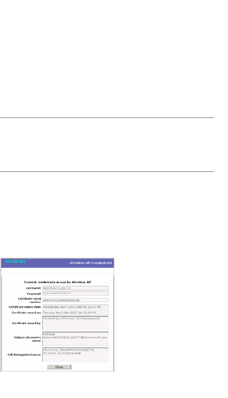
Configuring the Wireless AP
hwc_apstartup.fm
Configuring VLAN tags for Wireless APs
9034530-02, March 2010
176 HiPath Wireless Controller, Access Points and Convergence Software V7.11, User Guide
The 802.1x EAP-TLS authentication in pass through mode is assigned to the
Wireless AP. The Wireless AP can now be deployed to a 802.1x enabled
switch port.
4.5.1.3 Viewing 802.1x credentials
When 802.1x authentication is configured on a Wireless AP, the light bulb icon on
the 802.1x tab for the configured Wireless AP is lit to indicate which 802.1x
authentication method is used. A Wireless AP can be configured to use both
EAP-TLS and PEAP authentication methods. For example, when both EAP-TLS
and PEAP authentication methods are configured for the Wireless AP, both light
bulb icons on the 802.1x tab are lit.
Note: You can only view the 802.1x credentials of Wireless APs that have an
active session with the HiPath Wireless Controller. If you attempt to view the
credentials of a Wireless AP that does not have an active session, the Wireless
AP Credentials window displays the following message:
Unable to query Wireless AP: not connected.
To view current 802.1x credentials:
1. From the main menu, click Wireless AP Configuration. The HiPath
Wireless AP screen is displayed.
2. In the Wireless AP list, click the Wireless AP for which you want to view its
current 802.1x credentials.
3. In the Current Credentials section, click Get Certificate details. The
Wireless AP Credentials window is displayed.

hwc_apstartup.fm
Configuring the Wireless AP
Configuring VLAN tags for Wireless APs
9034530-02, March 2010
HiPath Wireless Controller, Access Points and Convergence Software V7.11, User Guide 177
4.5.1.4 Deleting 802.1x credentials
Caution: Exercise caution when deleting 802.1x credentials. For example,
deleting 802.1x credentials may prevent the Wireless AP from being
authenticated or to lose its connection with the HiPath Wireless Controller.
To delete current 802.1x credentials:
1. From the main menu, click Wireless AP Configuration. The HiPath
Wireless AP screen is displayed.
2. In the Wireless AP list, click the Wireless AP for which you want to delete its
current 802.1x credentials.
3. Do the following:
•To delete EAP-TLS credentials, click Delete EAP-TLS credentials.
•To delete PEAP credentials, click Delete PEAP credentials.
The credentials are deleted and the Wireless AP settings are updated.
Note: If you attempt to delete the 802.1x credentials of a Wireless AP that
currently does not have an active session with the HiPath Wireless Controller,
the credentials are only deleted after the Wireless AP connects with the
HiPath Wireless Controller.
4.5.2 Setting up 802.1x authentication for Wireless
APs using Multi-edit
In addition to configuring Wireless APs individually, you can also configure 802.1x
authentication for multiple Wireless APs simultaneously by using the AP 802.1x
Multi-edit feature.
When you use the AP 802.1x Multi-edit feature, you can choose to:
•Assign EAP-TLS authentication based on generated certificates to multiple
Wireless APs by uploading a .pfx, .cer, or .zip file.
•Assign PEAP credentials to multiple Wireless APs based on a user name and
password that you define
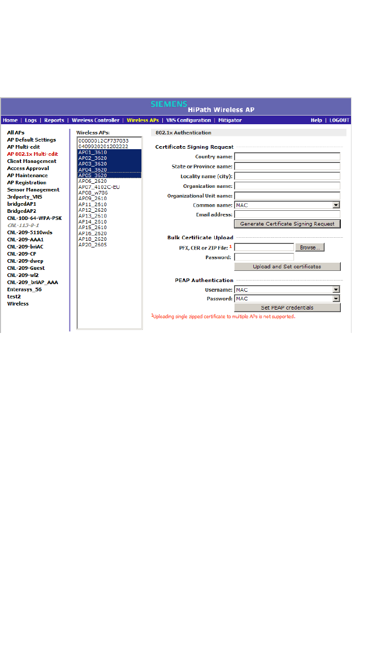
Configuring the Wireless AP
hwc_apstartup.fm
Configuring VLAN tags for Wireless APs
9034530-02, March 2010
178 HiPath Wireless Controller, Access Points and Convergence Software V7.11, User Guide
To configure 802.1x EAP-TLS authentication in proxy mode using
Multi-edit:
1. From the main menu, click Wireless AP Configuration. The HiPath
Wireless AP screen is displayed.
2. In the left pane, click AP 802.1x Multi-edit.
3. In the Wireless APs list, click one or more Wireless APs to configure. To
select multiple Wireless APs, click the Wireless APs from the list while
pressing the CTRL key.
4. In the Certificate Signing Request section, type the following:
• Country name – The two-letter ISO abbreviation of the name of the
country
• State or Province name – The name of the State/Province
• Locality name (city) – The name of the city
• Organization name – The name of the organization
• Organizational Unit name – The name of the unit within the organization
• Common name – Click the value you want to assign as the common
name of the Wireless AP:
•Name – The name of the Wireless AP, which is assigned on the AP
Properties tab. The Wireless AP name can be edited.
•Serial – The serial number of the Wireless AP. The Wireless AP serial
number cannot be edited.

hwc_apstartup.fm
Configuring the Wireless AP
Configuring VLAN tags for Wireless APs
9034530-02, March 2010
HiPath Wireless Controller, Access Points and Convergence Software V7.11, User Guide 179
•MAC – The MAC address of the Wireless AP. The Wireless AP MAC
address cannot be edited.
• Email address – The email address of the organization
5. Click Generate Certificates. The AP 802.1x Multi-edit progress window is
displayed, which provides the status of the configuration process. Once
complete, the File Download dialog is displayed.
6. Click Save. The Save as window is displayed.
7. Navigate to the location on your computer that you want to save the
generated certificate_requests.tar file, and then click Save.
The certificate_requests.tar file contains a certificate request (.csr) file for
each Wireless AP.
8. Do one of the following:
•For each certificate request, generate a certificate using the third-party
Certificate Authentication application. This method will produce a
certificate for each Wireless AP. Once complete, zip all the certificates
files (.cer) into one .zip file.
•Use one of the certificate requests and generate one certificate using the
Certificate Authentication application. This method will produce one
certificate that can be applied to all Wireless APs.
9. In the Bulk Certificate Upload section, click Browse. The Choose file
window is displayed.
10. Navigate to the location of the file (.zip or .cer), and then click Open. The
name of the file is displayed in the PFX,CER or ZIP Archive box.
11. Click Upload and Set certificates. Once complete, the Settings updated
message is displayed in the footer of the HiPath Wireless Assistant.
The 802.1x EAP-TLS authentication configuration is assigned to the Wireless
APs. The Wireless APs can now be deployed to 802.1x enabled switch ports.
Configuring 802.1x EAP-TLS authentication in pass through mode using
Multi-edit:
When you configure 802.1x EAP-TLS authentication in pass through mode using
Multi-edit, do one of the following:
•Generate a certificate for each Wireless AP using the third-party Certificate
Authentication application. When generating the certificates:
•Use the Common name value (either Name, Serial, or MAC) of the
Wireless AP to name each generated certificate.
•Use a common password for each generated certificate.

Configuring the Wireless AP
hwc_apstartup.fm
Configuring VLAN tags for Wireless APs
9034530-02, March 2010
180 HiPath Wireless Controller, Access Points and Convergence Software V7.11, User Guide
•All .pfx files created by the third-party Certificate Authentication
application must be zipped into one file.
•Generate one certificate, using the third-party Certificate Authentication
application, to be applied to all Wireless APs. When generating the certificate,
use the Common name value (either Name, Serial, or MAC) of the Wireless
AP to name the generated certificate.
To configure 802.1x EAP-TLS authentication in pass through mode using
Multi-edit:
1. From the main menu, click Wireless AP Configuration. The HiPath
Wireless AP screen is displayed.
2. In the left pane, click AP 802.1x Multi-edit.
3. In the Wireless APs list, click one or more Wireless APs to configure. To
select multiple Wireless APs, click the Wireless APs from the list while
pressing the CTRL key.
4. In the Bulk Certificate Upload section, click Browse. The Choose file
window is displayed.
5. Navigate to the location of the file (.zip or .pfx), and then click Open. The
name of the file is displayed in the PFX,CER or ZIP Archive box.
6. In the Password box, type the password used during the certificates
generation process.
7. Click Upload and Set certificates. Once complete, the Settings updated
message is displayed in the footer of the HiPath Wireless Assistant.
The 802.1x EAP-TLS authentication configuration is assigned to the Wireless
APs. The Wireless APs can now be deployed to 802.1x enabled switch ports.
To configure 802.1x PEAP authentication using Multi-edit:
1. From the main menu, click Wireless AP Configuration. The HiPath
Wireless AP screen is displayed.
2. In the left pane, click AP 802.1x Multi-edit.
3. In the Wireless APs list, click one or more APs to edit. To select multiple APs,
click the APs from the list while pressing the CTRL key.
4. In the PEAP Authentication section, do the following:
•In the Username drop-down list, click the value you want to assign as the
user name credential:
•Name – The name of the Wireless AP, which is assigned on the AP
Properties tab. The Wireless AP name can be edited.
•Serial – The serial number of the Wireless AP. The Wireless AP serial
number cannot be edited.

hwc_apstartup.fm
Configuring the Wireless AP
Configuring VLAN tags for Wireless APs
9034530-02, March 2010
HiPath Wireless Controller, Access Points and Convergence Software V7.11, User Guide 181
•MAC – The MAC address of the Wireless AP. The Wireless AP MAC
address cannot be edited.
•In the Password drop-down list, click the value you want to assign as the
password credential:
•Name – The name of the Wireless AP, which is assigned on the AP
Properties tab. The Wireless AP name can be edited.
•Serial – The serial number of the Wireless AP. The Wireless AP serial
number cannot be edited.
•MAC – The MAC address of the Wireless AP. The Wireless AP MAC
address cannot be edited.
5. Click Set PEAP credentials. The AP 802.1x Multi-edit progress window is
displayed, which provides the status of the configuration process. Once
complete, the Settings updated message is displayed in the footer of the
HiPath Wireless Assistant.
The 802.1x PEAP authentication configuration is assigned to the Wireless
APs. The Wireless APs can now be deployed to 802.1x enabled switch ports.
4.5.3 Configuring the default Wireless AP settings
Wireless APs are added with default settings. You can modify the system’s
Wireless AP default settings, and then use these default settings to configure
newly added Wireless APs. In addition, you can base the system’s Wireless AP
default settings on an existing Wireless AP configuration or have configured
Wireless APs inherit the properties of the default Wireless AP configuration when
they register with the system.
The process of configuring the default Wireless AP settings is divided into five
tabs:
• Common Configuration – Configure common configuration, such as WLAN
assignments and static configuration options for all Wireless APs.
• AP2610 AP2620 AP2605 W788 BP200 WB500 – Configure the default
settings for the standard Wireless APs, and the W788, BP200, and WB500
access points.
• AP3610 AP3620 – Configure the default settings for the Wireless 802.11n
APs.
• AP2650 AP2660 W786 – Configure the default settings for the HiPath
Wireless Outdoor APs and the W786 access points.
• AP4102 AP4102C – Configure the default settings for the AP4102 and the
AP4102C access points.
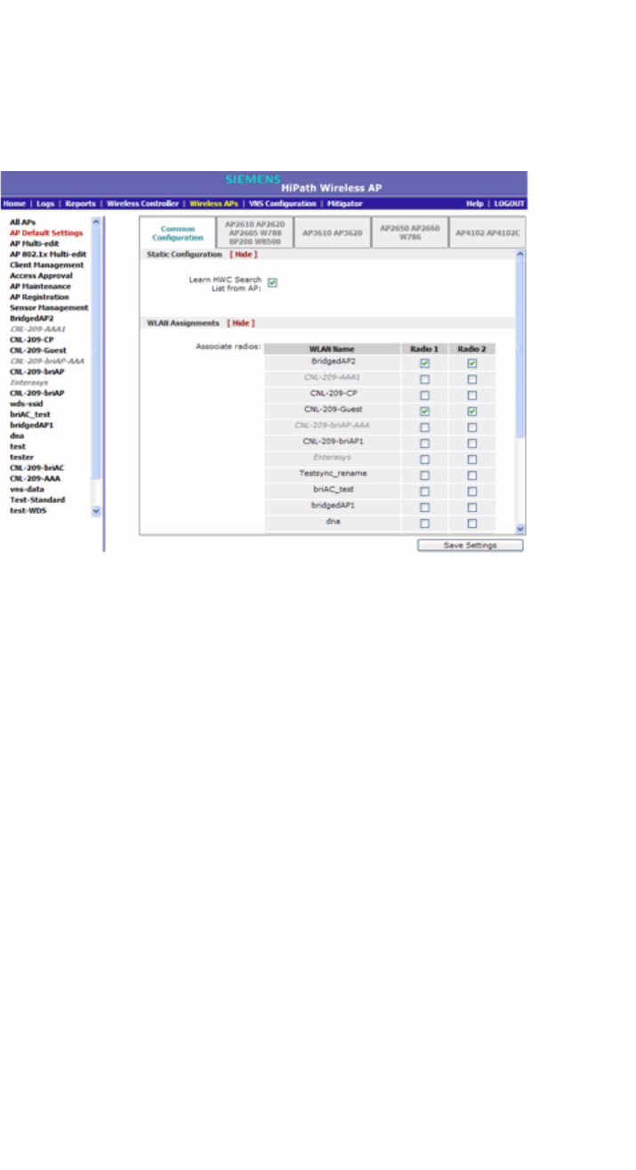
Configuring the Wireless AP
hwc_apstartup.fm
Configuring VLAN tags for Wireless APs
9034530-02, March 2010
182 HiPath Wireless Controller, Access Points and Convergence Software V7.11, User Guide
To configure common configuration default AP settings:
1. From the main menu, click Wireless AP Configuration. The HiPath
Wireless AP screen is displayed.
2. In the left pane, click AP Default Settings. The Common Configuration tab
is displayed.
3. In the Static Configuration section, do one of the following:
•To allow each Wireless AP to provide its own HWC Search List, select the
Learn HWC Search List from AP checkbox.
•To specify a common HWC Search List for all Wireless APs, clear the
Learn HWC Search List from AP checkbox, and then do the following:
a) In the Add box, type the IP address of the HiPath Wireless Controller
that will control this Wireless AP.
b) Click Add. The IP address is added to the list.
c) Repeat steps a and b to add additional HiPath Wireless
Controllers.The maximum is three controllers.
d) Click Up and Down to modify the order of the HiPath Wireless
Controllers.
The Wireless AP attempts to connect to the IP addresses in the order in which
they are listed. The Wireless AP is successful when it finds a HiPath Wireless
Controller that will allow it to register.
This feature allows the Wireless AP to bypass the discovery process. If the
Wireless Controller Search List box is not populated, the Wireless AP will
use SLP to discover a HiPath Wireless Controller.
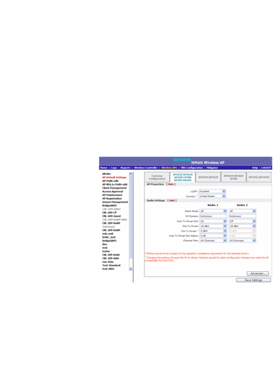
hwc_apstartup.fm
Configuring the Wireless AP
Configuring VLAN tags for Wireless APs
9034530-02, March 2010
HiPath Wireless Controller, Access Points and Convergence Software V7.11, User Guide 183
The DHCP function for wireless clients must be provided locally by a local
DHCP server, unless each wireless client has a static IP address.
For the initial Wireless AP deployment, it is necessary to use one of the
described options in Section 4.2, “Discovery and registration overview”, on
page 97.
4. In the WLAN Assignments section, assign the Radios for each VNS in the
list by selecting or clearing the option boxes.
5. To save your changes, click Save Settings.
To configure AP2610/20, AP2605, W788, BP200, and WB500 default access
point settings:
1. From the main menu, click Wireless AP Configuration. The HiPath
Wireless AP screen is displayed.
2. In the left pane, click AP Default Settings. The Common Configuration tab
is displayed.
3. Click the AP2610 AP2620 AP2605 W788 BP200 WB500 tab.
4. In the AP Properties section, do the following:
•LLDP – Click to Enable or Disable the Wireless AP from broadcasting
LLDP information. This option is disabled by default.
If SNMP is enabled on the HiPath Wireless Controller and you enable
LLDP, the LLDP Confirmation dialog is displayed.
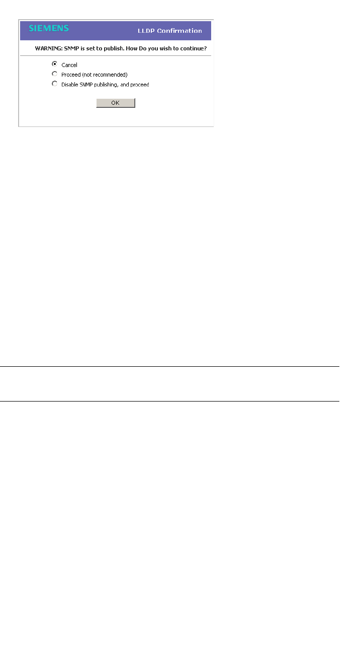
Configuring the Wireless AP
hwc_apstartup.fm
Configuring VLAN tags for Wireless APs
9034530-02, March 2010
184 HiPath Wireless Controller, Access Points and Convergence Software V7.11, User Guide
•Select one of the following:
• Proceed (not recommended) – Select this option to enable LLDP
and keep SNMP running, and then click OK.
• Disable SNMP publishing, and proceed – Select this option to
enable LLDP and disable SNMP, and then click OK.
For more information on enabling SNMP, see the HiPath Wireless
Controller, Access Points and Convergence Software Maintenance
Guide.
• Announcement Interval – If LLDP is enabled, type how often the
Wireless AP advertises its information by sending a new LLDP packet.
This value is measured in seconds.
If there are no changes to the Wireless AP configuration that impact the
LLDP information, the Wireless AP sends a new LLDP packet according
to this schedule.
Note: The Time to Live value cannot be directly edited. The Time to Live
value is calculated as four times the Announcement Interval value.
• Announcement Delay – If LLDP is enabled, type the announcement
delay. This value is measured in seconds. If a change to the Wireless AP
configuration occurs which impacts the LLDP information, the Wireless
AP sends an updated LLDP packet. The announcement delay is the
length of time that delays the new packet delivery. The announcement
delay helps minimize LLDP packet traffic.
• Country – Click the country of operation. This option is only available with
certain licenses.
5. In the Radio Settings section, do the following for each radio:
• Radio mode – Click the radio mode you want to enable:
• Radio 1 – off or a.

hwc_apstartup.fm
Configuring the Wireless AP
Configuring VLAN tags for Wireless APs
9034530-02, March 2010
HiPath Wireless Controller, Access Points and Convergence Software V7.11, User Guide 185
• Radio 2 – off, b, g, or b/g.
Note: Depending on the radio modes you select, some of the radio settings
may not be available for configuration.
•RF Domain – Type a string that uniquely identifies a group of APs that
cooperate in managing RF channels and transmission power levels. The
maximum length of the string is 16 characters. The RF Domain is used to
identify a group of Wireless APs.
• Auto Tx Power Ctrl – Click to either enable or disable ATPC from the
Auto Tx Power Ctrl drop-down list. ATPC automatically adapts
transmission power signals according to the coverage provided by the
Wireless APs. After a period of time, the system will stabilize itself based
on the RF coverage of your Wireless APs.
• Max Tx Power – Click the appropriate Tx power level from the Max TX
Power drop-down list. The values in the Max TX Power drop-down are
in dBm.
• Min Tx Power – If ATPC is enabled, click the minimum Tx power level to
which the range of transmit power can be adjusted: 0 to 23 (b/g or b/g/n)
or 24 (a or a/n) dBm. It is recommended to use 0 dBm if you do not want
to limit the potential Tx power level range that can be used.
• Auto Tx Power Ctrl Adjust – If ATPC is enabled, click the Tx power level
that can be used to adjust the ATPC power levels that the system has
assigned. It is recommended to use 0 dBm during your initial
configuration. If you have an RF plan that recommends Tx power levels
for each Wireless AP, compare the actual Tx power levels your system
has assigned against the recommended values your RF plan has
provided. Use the Auto Tx Power Ctrl Adjust value to achieve the
recommended values.
• Channel Plan – If ACS is enabled you can define a channel plan for the
Wireless AP. Defining a channel plan allows you to limit which channels
are available for use during an ACS scan. For example, you may want to
avoid using specific channels because of low power, regulatory domain,
or radar interference.
For Radio 1, click one of the following:
• All channels – ACS scans all channels for an operating channel and
returns both DFS and non-DFS channels, if available.
• All Non-DFS Channels – ACS scans all non-DFS channels for an
operating channel. This selection is available when there is at least
one DFS channel supported for the selected country.

Configuring the Wireless AP
hwc_apstartup.fm
Configuring VLAN tags for Wireless APs
9034530-02, March 2010
186 HiPath Wireless Controller, Access Points and Convergence Software V7.11, User Guide
•Custom – To configure individual channels from which the ACS will
select an operating channel, click Configure. The Custom Channel
Plan dialog displays. By default, all channels participate in the
channel plan. Click the individual channels you want to include in the
channel plan. To select contiguous channels, use the Shift key. To
select multiple, non-contiguous channels in the list, use the CTRL
key. Click OK to save the configuration.
For Radio 2, click one of the following:
• 3 Channel Plan – ACS will scan the following channels: 1, 6, and 11
in the US, and 1, 7, and 13 in Europe.
• 4 Channel Plan – ACS will scan the following channels: 1, 4, 7, and
11 in the US, and 1, 5, 9, and 13 in Europe.
•Auto – ACS will scan the default channel plan channels: 1, 6, and 11
in the US, and 1, 5, 9, and 13 in Europe.
•Custom – If you want to configure individual channels from which the
ACS will select an operating channel, click Configure. The Add
Channels dialog is displayed. Click the individual channels you want
to add to the channel plan while pressing the CTRL key, and then click
OK.
6. To modify default access point advanced settings, click Advanced. The
Advanced dialog is displayed.
7. In the Advanced dialog AP Properties section, do the following:
• Poll Timeout – Type the timeout value, in seconds. The Wireless AP
uses this value to trigger re-establishing the link with the HiPath Wireless
Controller if it (Wireless AP) does not get an answer to its polling. The
default value is 10 seconds.
Note: If you are configuring session availability, the Poll Timeout value
should be 1.5 to 2 times of Detect link failure value on AP Properties
screen. For more information, see Section 7.4, “Session availability”, on page
392.
• Telnet Access – Click to Enable or Disable telnet access to the Wireless
AP.
• Maintain client session in event of poll failure – Click to Enable or
Disable (if using a bridged at AP VNS) if the AP should remain active if a
link loss with the controller occurs.This option is enabled by default.
• Restart service in the absence of controller – Click to Enable or
Disable (if using a bridged at AP VNS) to ensure the Wireless APs’ radios
continue providing service if the Wireless AP’s connection to the HiPath

hwc_apstartup.fm
Configuring the Wireless AP
Configuring VLAN tags for Wireless APs
9034530-02, March 2010
HiPath Wireless Controller, Access Points and Convergence Software V7.11, User Guide 187
Wireless Controller is lost. If this option is enabled, it allows the Wireless
AP to start a bridged at AP VNS even in the absence of a HiPath Wireless
Controller.
• Use broadcast for disassociation – Click to Enable or Disable if you
want the Wireless AP to use broadcast disassociation when
disconnecting all clients, instead of disassociating each client one by one.
This will affect the behavior of the AP under the following conditions:
•If the Wireless AP is preparing to reboot or to enter one of the special
modes (DRM initial channel selection).
•If a BSSID is deactivated or removed on the Wireless AP.
This option is disabled by default.
8. In the Advanced dialog Radio Settings section, do the following:
•DTIM – Type the desired DTIM (Delivery Traffic Indication Message)
period — the number of beacon intervals between two DTIM beacons. To
ensure the best client power savings, use a large number. For example,
5. Use a small number to minimize broadcast and multicast delay. The
default value is 5.
• Beacon Period – Type the desired time, in milliseconds, between
beacon transmissions. The default value is 100 milliseconds.
• RTS/CTS – Type the packet size threshold, in bytes, above which the
packet will be preceded by an RTS/CTS (Request to Send/Clear to Send)
handshake. The default value is 2346, which means all packets are sent
without RTS/CTS. Reduce this value only if necessary.
• Frag. Threshold – Type the fragment size threshold, in bytes, above
which the packets will be fragmented by the AP prior to transmission. The
default value is 2346, which means all packets are sent unfragmented.
• Max % of non-unicast traffic per Beacon period – Enter the maximum
percentage of time that the AP will transmit non-unicast packets
(broadcast and multicast traffic) for each configured Beacon Period. For
each non-unicast packet transmitted, the system calculates the airtime
used by eack packet and drops all packets that exceed the configured
maximum percentage. By restricting non-unicast traffic, you limit the
impact of broadcasts and multicasts on overall system performance.
• Maximum Distance – Enter a value from 100 to 15,000 meters that
identifies the maximum link distance between APs that participate in a
WDS. This value ensures that the acknowledgement of communication
between APs does not exceed the timeout value predefined by the 802.11
standard. The default value is 100 meters. If the link distance between
APs is greater than 100 meters, configure the maximum distance up to
15,000 meters so that the software increases the timeout value
proportionally with the distance between APs.

Configuring the Wireless AP
hwc_apstartup.fm
Configuring VLAN tags for Wireless APs
9034530-02, March 2010
188 HiPath Wireless Controller, Access Points and Convergence Software V7.11, User Guide
Do not change the default setting for the radio that provides service to
802.11 clients only.
• Dynamic Channel Selection – Click one of the following:
•Off – Disables DCS.
• Monitor Mode – If traffic or noise levels exceed the configured DCS
thresholds, an alarm is triggered and an information log is generated.
• Active Mode – If traffic or noise levels exceed the configured DCS
thresholds, an alarm is triggered and an information log is generated.
In addition, the Wireless AP will cease operating on the current
channel and ACS is employed to automatically select an alternate
channel for the Wireless AP to operate on.
• DCS Noise Threshold – If DCS is enabled, type the noise
interference level, measured in dBm, after which ACS will scan for a
new operating channel for the Wireless AP if the threshold is
exceeded.
• DCS Channel Occupancy Threshold – If DCS is enabled, type the
channel utilization level, measured as a percentage, after which ACS
will scan for a new operating channel for the Wireless AP if the
threshold is exceeded.
• DCS Update Period – If DCS is enabled, type the time, measured in
minutes that determines the period during which the Wireless AP
averages the DCS Noise Threshold and DCS Channel Occupancy
Threshold measurements. If either one of these thresholds is
exceeded, then the Wireless AP will trigger ACS.
• Rx Diversity – Cick Best for the best signal from both antennas, or Left
or Right to choose either of the two diversity receiving antennas. The
default and recommended selection is Best. If only one antenna is
connected, use the corresponding Left or Right diversity setting. Do not
use Best if two identical antennas are not used.
• Tx Diversity – Click Alternate for the best signal from both antennas, or
Left or Right to choose either of the two diversity receiving antennas. The
default selection is Alternate that maximizes performance for most
clients. However, some clients may behave oddly with Tx Diversity set to
Alternate. Under those circumstances, it is recommended to use either
Left or Right for Tx Diversity. If only one antenna is connected, use the
corresponding Left or Right diversity setting. Do not use Alternate if two
identical antennas are not used.
•Preamble – Click a preamble type for 11b-specific (CCK) rates: Short,
Long, or Auto. The recommended value is Auto. Click Short if you are
sure that there is no pre-11b AP or a client in the vicinity of this AP. Click
Long if compatibility with pre-11b clients is required.

hwc_apstartup.fm
Configuring the Wireless AP
Configuring VLAN tags for Wireless APs
9034530-02, March 2010
HiPath Wireless Controller, Access Points and Convergence Software V7.11, User Guide 189
• Protection Mode – Click a protection mode: None, Auto, or Always.
The default and recommended setting is Auto. Click None if 11b APs and
clients are not expected. Click Always if you expect many 11b-only
clients.
•Protection Rate – Click a protection rate: 1, 2, 5.5, or 11 Mbps. The
default and recommended setting is 11. Only reduce the rate if there are
many 11b clients in the environment or if the deployment has areas with
poor coverage. For example, rates lower than 11 Mbps are required to
ensure coverage.
• Protection Type – Click a protection type: CTS Only or RTS CTS. The
default and recommended setting is CTS Only. Click RTS CTS only if an
11b AP that operates on the same channel is detected in the
neighborhood, or if there are many 11b-only clients in the environment.
9. In the Advanced dialog Enhanced Rate Control section, do the following:
• Min Basic Rate – For each radio, click the minimum data rate that must
be supported by all stations in a BSS: 1, 2, 5.5, or 11 Mbps for 11b and
11b+11g modes. Click 1, 2, 5.5, 6, 11, 12, or 24 Mbps for 11g-only mode.
Click 6, 12, or 24 Mbps for 11a mode. If necessary, the Max Basic Rate
choices adjust automatically to be higher or equal to the Min Basic Rate.
If both Min Basic Rate and Max Basic Rate are set to an 11g-specific
(OFDM) rate, (for example, 6, 12, or 24 Mbps) all basic rates will be 11g-
specific.
• Max Basic Rate – For each radio, click the maximum data rate that must
be supported by all stations in a BSS: 1, 2, 5.5, or 11 Mbps for 11b and
11b+11g modes. Click 1, 2, 5.5, 6, 11, 12, or 24 Mbps for 11g-only mode.
Click 6, 12, or 24 Mbps for 11a mode. If necessary, the Max Basic Rate
choices adjust automatically to be higher or equal to the Min Basic Rate.
If both Min Basic Rate and Max Basic Rate are set to an 11g-specific
(OFDM) rate, (for example, 6, 12, or 24 Mbps) all basic rates will be 11g-
specific.
• Max Operational Rate – For each radio, click the maximum data rate that
clients can operate at while associated with the AP: 1, 2, 5.5, or 11 Mbps
for 11b-only mode. Click 1, 2, 5.5, 6, 9, 11, 12, 18, 24, 36, 28, or 54 Mbps
for 11b+11g or 11g-only modes. Click 6, 9, 12, 18, 24, 36, 48, or 54 Mbps
for 11a mode. If necessary, the Max Operational Rate choices adjust
automatically to be higher or equal to the Min Basic Rate.
10. In the Advanced dialog No of Retries section, do the following:
• Background BK – For each radio, click the number of retries for the
Background transmission queue. The default value is adaptive (multi-
rate). The recommended setting is adaptive (multi-rate).
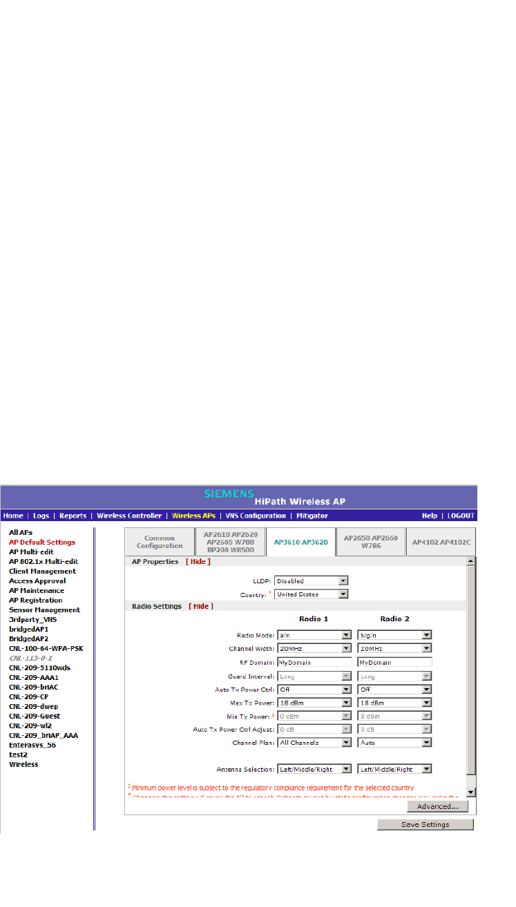
Configuring the Wireless AP
hwc_apstartup.fm
Configuring VLAN tags for Wireless APs
9034530-02, March 2010
190 HiPath Wireless Controller, Access Points and Convergence Software V7.11, User Guide
• Best Effort BE – For each radio, click the number of retries for the Best
Effort transmission queue. The default value is adaptive (multi-rate).
The recommended setting is adaptive (multi-rate).
•Video VI – For each radio, click the number of retries for the Video
transmission queue. The default value is adaptive (multi-rate). The
recommended setting is adaptive (multi-rate).
• Voice VO – For each radio, click the number of retries for the Voice
transmission queue. The default value is adaptive (multi-rate). The
recommended setting is adaptive (multi-rate).
• Turbo Voice TVO – For each radio, click the number of retries for the
Turbo Voice transmission queue. The default value is adaptive (multi-
rate). The recommended setting is adaptive (multi-rate).
11. Click Close. The Advanced dialog is closed.
12. To save your changes, click Save Settings.
To configure AP3610/20 default access point settings:
1. From the main menu, click Wireless AP Configuration. The HiPath
Wireless AP screen is displayed.
2. In the left pane, click AP Default Settings. The Common Configuration tab
is displayed.
3. Click the AP3610 AP3620 tab.
4. In the AP Properties section, do the following:
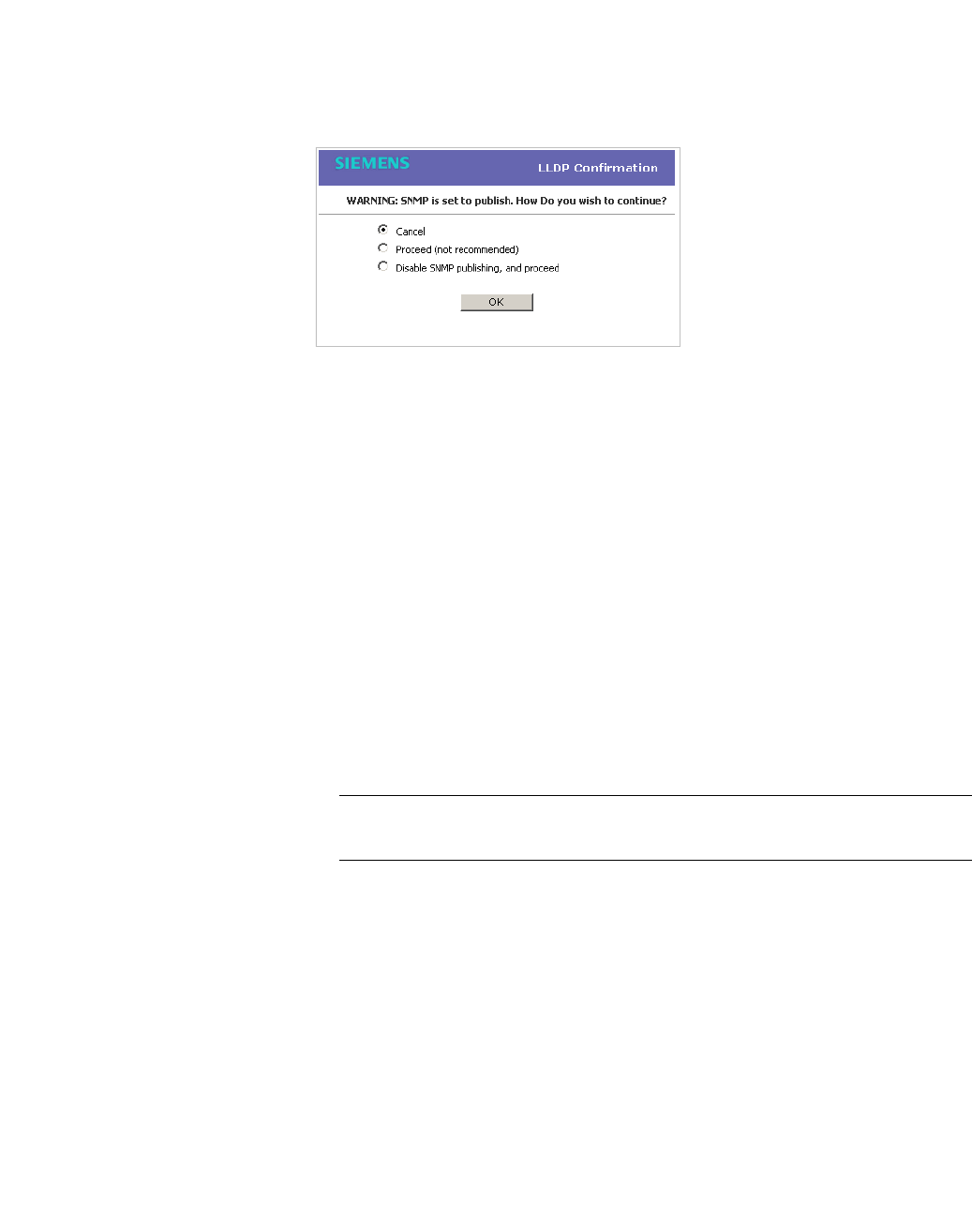
hwc_apstartup.fm
Configuring the Wireless AP
Configuring VLAN tags for Wireless APs
9034530-02, March 2010
HiPath Wireless Controller, Access Points and Convergence Software V7.11, User Guide 191
•LLDP – Click to enable or disable the Wireless AP from broadcasting
LLDP information. This option is disabled by default.
If SNMP is enabled on the HiPath Wireless Controller and you enable
LLDP, the LLDP Confirmation dialog is displayed.
•Select one of the following:
• Proceed (not recommended) – Select this option to enable LLDP
and keep SNMP running, and then click OK.
• Disable SNMP publishing, and proceed – Select this option to
enable LLDP and disable SNMP, and then click OK.
For more information on enabling SNMP, see the HiPath Wireless
Controller, Access Points and Convergence Software Maintenance
Guide.
• Announcement Interval – If LLDP is enabled, type how often the
Wireless AP advertises its information by sending a new LLDP packet.
This value is measured in seconds.
If there are no changes to the Wireless AP configuration that impact the
LLDP information, the Wireless AP sends a new LLDP packet according
to this schedule.
Note: The Time to Live value cannot be directly edited. The Time to Live
value is calculated as four times the Announcement Interval value.
• Announcement Delay – If LLDP is enabled, type the announcement
delay. This value is measured in seconds. If a change to the Wireless AP
configuration occurs which impacts the LLDP information, the Wireless
AP sends an updated LLDP packet. The announcement delay is the
length of time that delays the new packet delivery. The announcement
delay helps minimize LLDP packet traffic.
• Country – Click the country of operation. This option is only available with
some licenses.
5. In the Radio Settings section, do the following for each radio:
• Radio mode – Click the radio mode you want to enable:

Configuring the Wireless AP
hwc_apstartup.fm
Configuring VLAN tags for Wireless APs
9034530-02, March 2010
192 HiPath Wireless Controller, Access Points and Convergence Software V7.11, User Guide
• Radio 1 – off, a or a/n.
• Radio 2 – off, b, b/g, or b/g/n.
Note: Depending on the radio modes you select, some of the radio settings
may not be available for configuration.
• Channel Width – Click the channel width for the radio:
•20MHz – Click to allow 802.11n clients to use the primary channel
(20MHz) and non-802.11n clients, beacons, and multicasts to use the
802.11b/g radio protocols.
•40MHz – Click to allow 802.11n clients that support the 40MHz
frequency to use 40MHz, 20MHz, or the 802.11b/g radio protocols.
802.11n clients that do not support the 40MHz frequency can use
20MHz or the 802.11b/g radio protocols and non-802.11n clients,
beacons, and multicasts use the 802.11b/g radio protocols.
•Auto – Click to automatically switch between 20MHz and 40MHz
channel widths, depending on how busy the extension channel is.
•RF Domain – Type a string that uniquely identifies a group of APs that
cooperate in managing RF channels and transmission power levels. The
maximum length of the string is 16 characters. The RF Domain is used to
identify a group of Wireless APs.
• Guard Interval – Click a guard interval, Long or Short, when a 40MHz
channel is used. It is recommended to use a short guard interval in small
rooms (for example, a small office space) and a long guard interval in
large rooms (for example, a conference hall).
• Auto Tx Power Ctrl – Click to enable or disable ATPC from the Auto Tx
Power Ctrl drop-down list. ATPC automatically adapts transmission
power signals according to the coverage provided by the Wireless APs.
After a period of time, the system will stabilize itself based on the RF
coverage of your Wireless APs.
•Max Tx Power – Click the appropriate Tx power level from the Max TX
Power drop-down list. The values in the Max TX Power drop-down are
in dBm.
•Min Tx Power – If ATPC is enabled, click the minimum Tx power level to
which the range of transmit power can be adjusted:0 to 23 (b/g or b/g/n)
or 24 (a or a/n) dBm. It is recommended to use 0 dBm to not limit the
potential Tx power level range that can be used.
• Auto Tx Power Ctrl Adjust – If ATPC is enabled, click the Tx power level
that can be used to adjust the ATPC power levels that the system has
assigned. It is recommended to use 0 dBm during your initial
configuration. If you have an RF plan that recommends Tx power levels

hwc_apstartup.fm
Configuring the Wireless AP
Configuring VLAN tags for Wireless APs
9034530-02, March 2010
HiPath Wireless Controller, Access Points and Convergence Software V7.11, User Guide 193
for each Wireless AP, compare the actual Tx power levels your system
has assigned against the recommended values your RF plan has
provided. Use the Auto Tx Power Ctrl Adjust value to achieve the
recommended values.
• Channel Plan – If ACS is enabled, you can define a channel plan for the
Wireless AP. Defining a channel plan allows you to limit which channels
are available for use during an ACS scan. For example, you may want to
avoid using specific channels because of low power, regulatory domain,
or radar interference.
For Radio 1, click one of the following:
• All channels – ACS scans all channels for an operating channel and
returns both DFS and non-DFS channels, if available.
• All Non-DFS Channels – ACS scans all non-DFS channels for an
operating channel. This selection is available when there is at least
one DFS channel supported for the selected country.
•Custom – To configure individual channels from which the ACS will
select an operating channel, click Configure. The Custom Channel
Plan dialog displays. By default, all channels participate in the
channel plan. Click the individual channels you want to include in the
channel plan. To select contiguous channels, use the Shift key. To
select multiple, non-contiguous channels in the list, use the CTRL
key. Click OK to save the configuration.
For Radio 2, click one of the following:
• 3 Channel Plan – ACS will scan the following channels: 1, 6, and 11
in the US, and 1, 7, and 13 in Europe.
• 4 Channel Plan – ACS will scan the following channels: 1, 4, 7, and
11 in the US, and 1, 5, 9, and 13 in Europe.
•Auto – ACS will scan the default channel plan channels: 1, 6, and 11
in the US, and 1, 5, 9, and 13 in Europe.
•Custom – If you want to configure individual channels from which the
ACS will select an operating channel, click Configure. The Add
Channels dialog is displayed. Click the individual channels you want
to add to the channel plan while pressing the CTRL key, and then click
OK.
• Antenna Selection – Click the antenna, or antenna combination, you
want to configure on this radio.
When you configure the Wireless 802.11n AP to use specific antennas,
the transmission power is recalculated; the Current Tx Power Level
value for the radio is automatically adjusted to reflect the recent antenna
configuration. It takes approximately 30 seconds for the change to the

Configuring the Wireless AP
hwc_apstartup.fm
Configuring VLAN tags for Wireless APs
9034530-02, March 2010
194 HiPath Wireless Controller, Access Points and Convergence Software V7.11, User Guide
Current Tx Power Level value to be reflected in the HiPath Wireless
Assistant. Also, the radio is reset causing client connections on this radio
to be lost.
6. To modify default access point advanced settings, click Advanced. The
Advanced dialog is displayed.
7. In the Advanced dialog AP Properties section, do the following:
• Poll Timeout – Type the timeout value, in seconds. The Wireless AP
uses this value to trigger re-establishing the link with the HiPath Wireless
Controller if it (Wireless AP) does not get an answer to its polling. The
default value is 10 seconds.
Note: If you are configuring session availability, the Poll Timeout value
should be 1.5 to 2 times of Detect link failure value on AP Properties
screen. For more information, see Section 7.4, “Session availability”, on page
392.
• Maintain client session in event of poll failure – Select this option (if
using a bridged at AP VNS) if the AP should remain active if a link loss
with the controller occurs.This option is enabled by default.
• Restart service in the absence of controller – Select this option (if
using a bridged at AP VNS) to ensure the Wireless AP’s radios continue
providing service if the Wireless AP’s connection to the HiPath Wireless
Controller is lost. If this option is enabled, it allows the Wireless AP to start
a bridged at AP VNS even in the absence of a HiPath Wireless Controller.
• Use broadcast for disassociation – Select if you want the Wireless AP
to use broadcast disassociation when disconnecting all clients, instead of
disassociating each client one by one. This will affect the behavior of the
AP under the following conditions:
•If the Wireless AP is preparing to reboot or to enter one of the special
modes (DRM initial channel selection).
•If a BSSID is deactivated or removed on the Wireless AP.
This option is disabled by default.
8. In the Advanced dialog Radio Settings section, do the following:
•DTIM – Type the desired DTIM (Delivery Traffic Indication Message)
period — the number of beacon intervals between two DTIM beacons. To
ensure the best client power savings, use a large number. For example,
5. Use a small number to minimize broadcast and multicast delay. The
default value is 5.
• Beacon Period – Type the desired time, in milliseconds, between
beacon transmissions. The default value is 100 milliseconds.

hwc_apstartup.fm
Configuring the Wireless AP
Configuring VLAN tags for Wireless APs
9034530-02, March 2010
HiPath Wireless Controller, Access Points and Convergence Software V7.11, User Guide 195
• RTS/CTS – Type the packet size threshold, in bytes, above which the
packet will be preceded by an RTS/CTS (Request to Send/Clear to Send)
handshake. The default value is 2346, which means all packets are sent
without RTS/CTS. Reduce this value only if necessary.
• Frag. Threshold – For each radio, type the fragment size threshold, in
bytes, above which the packets will be fragmented by the AP prior to
transmission. The default value is 2346, which means all packets are sent
unfragmented. Reduce this value only if necessary.
• Max % of non-unicast traffic per Beacon period – Enter the maximum
percentage of time that the AP will transmit non-unicast packets
(broadcast and multicast traffic) for each configured Beacon Period. For
each non-unicast packet transmitted, the system calculates the airtime
used by eack packet and drops all packets that exceed the configured
maximum percentage. By restricting non-unicast traffic, you limit the
impact of broadcasts and multicasts on overall system performance.
• Maximum Distance – Enter a value from 100 to 15,000 meters that
identifies the maximum link distance between APs that participate in a
WDS. This value ensures that the acknowledgement of communication
between APs does not exceed the timeout value predefined by the 802.11
standard. The default value is 100 meters. If the link distance between
APs is greater than 100 meters, configure the maximum distance up to
15,000 meters so that the software increases the timeout value
proportionally with the distance between APs.
Do not change the default setting for the radio that provides service to
802.11 clients only.
• Dynamic Channel Selection – To enable Dynamic Channel Selection,
click one of the following:
• Monitor Mode – If traffic or noise levels exceed the configured DCS
thresholds, an alarm is triggered and an information log is generated.
• Active Mode – If traffic or noise levels exceed the configured DCS
thresholds, an alarm is triggered and an information log is generated.
In addition, the Wireless AP will cease operating on the current
channel and ACS is employed to automatically select an alternate
channel for the Wireless AP to operate on.
• DCS Noise Threshold – Type the noise interference level, measured in
dBm, after which ACS will scan for a new operating channel for the
Wireless AP if the threshold is exceeded.
• DCS Channel Occupancy Threshold – Type the channel utilization
level, measured as a percentage, after which ACS will scan for a new
operating channel for the Wireless AP if the threshold is exceeded.

Configuring the Wireless AP
hwc_apstartup.fm
Configuring VLAN tags for Wireless APs
9034530-02, March 2010
196 HiPath Wireless Controller, Access Points and Convergence Software V7.11, User Guide
• DCS Update Period – Type the time, measured in minutes that
determines the period during which the Wireless AP averages the DCS
Noise Threshold and DCS Channel Occupancy Threshold
measurements. If either one of these thresholds is exceeded, then the
Wireless AP will trigger ACS.
•Preamble – Click a preamble type for 11b-specific (CCK) rates: Short,
Long, or Auto. The recommended value is Auto. Click Short if you are
sure that there is no pre-11b AP or a client in the vicinity of this AP. Click
Long if compatibility with pre-11b clients is required.
• Protection Mode – Click a protection mode: None, Auto, or Always.
The default and recommended setting is Auto. Click None if 11b APs and
clients are not expected. Click Always if you expect many 11b-only
clients.
• Protection Rate – Click a protection rate: 1, 2, 5.5, or 11 Mbps. The
default and recommended setting is 11. Only reduce the rate if there are
many 11b clients in the environment or if the deployment has areas with
poor coverage. For example, rates lower than 11 Mbps are required to
ensure coverage.
• Protection Type – Click a protection type: CTS Only or RTS CTS. The
default and recommended setting is CTS Only. Click RTS CTS only if an
11b AP that operates on the same channel is detected in the
neighborhood, or if there are many 11b-only clients in the environment.
9. In the Advanced dialog 11n Settings section, do the following:
• Protection Mode – Click a protection mode: None, Auto, or Always.
The default and recommended setting is Auto. Click None if 11b APs and
clients are not expected. Click Always if you expect many 11b-only
clients.
• 40MHz Protection Mode – Click a protection type, CTS Only or RTS-
CTS, or None, when a 40MHz channel is used. This protects high
throughput transmissions on extension channels from interference from
non-11n APs and clients.
• 40MHz Prot. Channel Offset – Select a 20MHz channel offset if the
deployment is using channels that are 20MHz apart (for example, using
channels 1, 5, 9, and 13) or a 25MHz channel offset if the deployment is
using channels that are 25MHz apart (for example, using channels 1, 6,
and 11).
• 40MHz Channel Busy Threshold – Type the extension channel
threshold percentage, which if exceeded, will disable transmissions on
the extension channel (40MHz).
• Aggregate MSDUs – Click an aggregate MSDU mode: Enabled or
Disabled. Aggregate MSDU increases the maximum frame transmission
size.
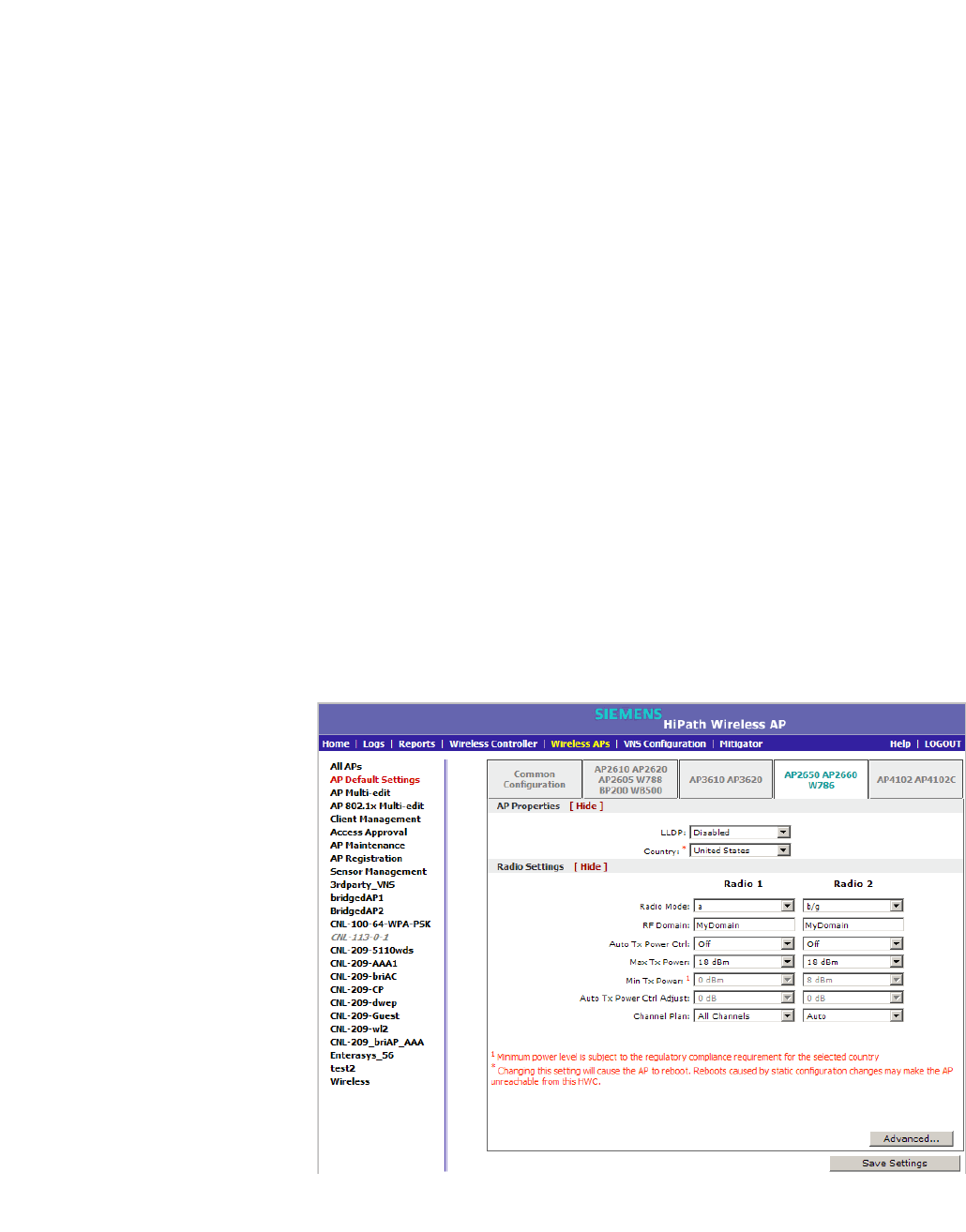
hwc_apstartup.fm
Configuring the Wireless AP
Configuring VLAN tags for Wireless APs
9034530-02, March 2010
HiPath Wireless Controller, Access Points and Convergence Software V7.11, User Guide 197
• Aggregate MSDU Max Length – Type the maximum length of the
aggregate MSDU. The value range is 2290-4096 bytes.
• Aggregate MPDUs – Click an aggregate MPDU mode: Enabled or
Disabled. Aggregate MPDU provides a significant improvement in
throughput.
• Aggregate MPDU Max Length – Type the maximum length of the
aggregate MPDU. The value range is 1024-65535 bytes.
• Agg. MPDU Max # of Sub-frames – Type the maximum number of
sub-frames of the aggregate MPDU. The value range is 2-64.
• ADDBA Support – Click an ADDBA support mode: Enabled or
Disabled. ADDBA, or block acknowledgement, provides
acknowledgement of a group of frames instead of a single frame. ADDBA
Support must be enabled if Aggregate APDU is enable.
10. Click Close. The Advanced dialog is closed.
11. To save your changes, click Save Settings.
To configure AP2650/60 and W786s default access point settings:
1. From the main menu, click Wireless AP Configuration. The HiPath
Wireless AP screen is displayed.
2. In the left pane, click AP Default Settings. The Common Configuration tab
is displayed.
3. Click the AP2650 AP2660 W786 tab.

Configuring the Wireless AP
hwc_apstartup.fm
Configuring VLAN tags for Wireless APs
9034530-02, March 2010
198 HiPath Wireless Controller, Access Points and Convergence Software V7.11, User Guide
4. In the AP Properties section, do the following:
• LLDP – Click to Enable or Disable the Wireless AP from broadcasting
LLDP information. This option is disabled by default.
If SNMP is enabled on the HiPath Wireless Controller and you enable
LLDP, the LLDP Confirmation dialog is displayed.
•Select one of the following:
• Proceed (not recommended) – Select this option to enable LLDP
and keep SNMP running, and then click OK.
• Disable SNMP publishing, and proceed – Select this option to
enable LLDP and disable SNMP, and then click OK.
For more information on enabling SNMP, see the HiPath Wireless
Controller, Access Points and Convergence Software Maintenance
Guide.
• Announcement Interval – If LLDP is enabled, type how often the
Wireless AP advertises its information by sending a new LLDP packet.
This value is measured in seconds.
If there are no changes to the Wireless AP configuration that impact the
LLDP information, the Wireless AP sends a new LLDP packet according
to this schedule.
Note: The Time to Live value cannot be directly edited. The Time to Live
value is calculated as four times the Announcement Interval value.
• Announcement Delay – If LLDP is enabled, type the announcement
delay. This value is measured in seconds. If a change to the Wireless AP
configuration occurs which impacts the LLDP information, the Wireless
AP sends an updated LLDP packet. The announcement delay is the
length of time that delays the new packet delivery. The announcement
delay helps minimize LLDP packet traffic.
5. Country – Click the country of operation. This option is only available with
some licenses.
6. In the Radio Settings section, do the following for each radio:

hwc_apstartup.fm
Configuring the Wireless AP
Configuring VLAN tags for Wireless APs
9034530-02, March 2010
HiPath Wireless Controller, Access Points and Convergence Software V7.11, User Guide 199
• Radio mode – Click the radio mode you want to enable:
• Radio 1 – off, b, g, b/g, or a.
• Radio 2 – off, b, g, b/g, or a.
Note: Depending on the radio modes you select, some of the radio settings
may not be available for configuration.
•RF Domain – Type a string that uniquely identifies a group of APs that
cooperate in managing RF channels and transmission power levels. The
maximum length of the string is 16 characters. The RF Domain is used to
identify a group of Wireless APs.
• Auto Tx Power Ctrl – Click to either enable or disable ATPC from the
Auto Tx Power Ctrl drop-down list. ATPC automatically adapts
transmission power signals according to the coverage provided by the
Wireless APs. After a period of time, the system will stabilize itself based
on the RF coverage of your Wireless APs.
• Max Tx Power – Click the appropriate Tx power level from the Max TX
Power drop-down list. The values in the Max TX Power drop-down are
in dBm.
• Min Tx Power – If ATPC is enabled, click the minimum Tx power level to
which the range of transmit power can be adjusted:0 to 23 (b/g or b/g/n)
or 24 (a or a/n) dBm. It is recommended to use 0 dBm to not limit the
potential Tx power level range that can be used.
• Auto Tx Power Ctrl Adjust – If ATPC is enabled, click the Tx power level
that can be used to adjust the ATPC power levels that the system has
assigned. It is recommended to use 0 dBm during your initial
configuration. If you have an RF plan that recommends Tx power levels
for each Wireless AP, compare the actual Tx power levels your system
has assigned against the recommended values your RF plan has
provided. Use the Auto Tx Power Ctrl Adjust value to achieve the
recommended values.
• Channel Plan – If ACS is enabled you can define a channel plan for the
Wireless AP. Defining a channel plan allows you to limit which channels
are available for use during an ACS scan. For example, you may want to
avoid using specific channels because of low power, regulatory domain,
or radar interference.
For Radio 1, click one of the following:
• All channels – ACS scans all channels for an operating channel and
returns both DFS and non-DFS channels, if available.

Configuring the Wireless AP
hwc_apstartup.fm
Configuring VLAN tags for Wireless APs
9034530-02, March 2010
200 HiPath Wireless Controller, Access Points and Convergence Software V7.11, User Guide
• All Non-DFS Channels – ACS scans all non-DFS channels for an
operating channel. This selection is available when there is at least
one DFS channel supported for the selected country.
•Custom – To configure individual channels from which the ACS will
select an operating channel, click Configure. The Custom Channel
Plan dialog displays. By default, all channels participate in the
channel plan. Click the individual channels you want to include in the
channel plan. To select contiguous channels, use the Shift key. To
select multiple, non-contiguous channels in the list, use the CTRL
key. Click OK to save the configuration.
For Radio 2, click one of the following:
• 3 Channel Plan – ACS will scan the following channels: 1, 6, and 11
in the US, and 1, 7, and 13 in Europe.
• 4 Channel Plan – ACS will scan the following channels: 1, 4, 7, and
11 in the US, and 1, 5, 9, and 13 in Europe.
•Auto – ACS will scan the default channel plan channels: 1, 6, and 11
in the US, and 1, 5, 9, and 13 in Europe.
•Custom – If you want to configure individual channels from which the
ACS will select an operating channel, click Configure. The Add
Channels dialog is displayed. Click the individual channels you want
to add to the channel plan while pressing the CTRL key, and then click
OK.
7. To modify default access point advanced settings, click Advanced. The
Advanced dialog is displayed.
8. In the Advanced dialog AP Properties section, do the following:
• Poll Timeout – Type the timeout value, in seconds. The Wireless AP
uses this value to trigger re-establishing the link with the HiPath Wireless
Controller if it (Wireless AP) does not get an answer to its polling. The
default value is 10 seconds.
Note: If you are configuring session availability, the Poll Timeout value
should be 1.5 to 2 times of Detect link failure value on AP Properties
screen. For more information, see Section 7.4, “Session availability”, on page
392.
• Telnet Access – Click to Enable or Disable telnet access to the Wireless
AP.
• Maintain client session in event of poll failure – Select this option (if
using a bridged at AP VNS) if the AP should remain active if a link loss
with the controller occurs.This option is enabled by default.

hwc_apstartup.fm
Configuring the Wireless AP
Configuring VLAN tags for Wireless APs
9034530-02, March 2010
HiPath Wireless Controller, Access Points and Convergence Software V7.11, User Guide 201
• Restart service in the absence of controller – Select this option (if
using a bridged at AP VNS) to ensure the Wireless AP’s radios continue
providing service if the Wireless AP’s connection to the HiPath Wireless
Controller is lost. If this option is enabled, it allows the Wireless AP to start
a bridged at AP VNS even in the absence of a HiPath Wireless Controller.
• Use broadcast for disassociation – Select if you want the Wireless AP
to use broadcast disassociation when disconnecting all clients, instead of
disassociating each client one by one. This will affect the behavior of the
AP under the following conditions:
•If the Wireless AP is preparing to reboot or to enter one of the special
modes (DRM initial channel selection).
•If a BSSID is deactivated or removed on the Wireless AP.
This option is disabled by default.
9. In the Advanced dialog Radio Settings section, do the following:
•DTIM – Type the desired DTIM (Delivery Traffic Indication Message)
period — the number of beacon intervals between two DTIM beacons. To
ensure the best client power savings, use a large number. For example,
5. Use a small number to minimize broadcast and multicast delay. The
default value is 5.
• Beacon Period – Type the desired time, in milliseconds, between
beacon transmissions. The default value is 100 milliseconds.
• RTS/CTS – Type the packet size threshold, in bytes, above which the
packet will be preceded by an RTS/CTS (Request to Send/Clear to Send)
handshake. The default value is 2346, which means all packets are sent
without RTS/CTS. Reduce this value only if necessary.
• Frag. Threshold – Type the fragment size threshold, in bytes, above
which the packets will be fragmented by the AP prior to transmission. The
default value is 2346, which means all packets are sent unfragmented.
Reduce this value only if necessary.
• Max % of non-unicast traffic per Beacon period – Enter the maximum
percentage of time that the AP will transmit non-unicast packets
(broadcast and multicast traffic) for each configured Beacon Period. For
each non-unicast packet transmitted, the system calculates the airtime
used by eack packet and drops all packets that exceed the configured
maximum percentage. By restricting non-unicast traffic, you limit the
impact of broadcasts and multicasts on overall system performance.
• Maximum Distance – Enter a value from 100 to 15,000 meters that
identifies the maximum link distance between APs that participate in a
WDS. This value ensures that the acknowledgement of communication
between APs does not exceed the timeout value predefined by the 802.11
standard. The default value is 100 meters. If the link distance between

Configuring the Wireless AP
hwc_apstartup.fm
Configuring VLAN tags for Wireless APs
9034530-02, March 2010
202 HiPath Wireless Controller, Access Points and Convergence Software V7.11, User Guide
APs is greater than 100 meters, configure the maximum distance up to
15,000 meters so that the software increases the timeout value
proportionally with the distance between APs.
Do not change the default setting for the radio that provides service to
802.11 clients only.
• Dynamic Channel Selection – Click one of the following:
•Off – Disables DCS.
• Monitor Mode – If traffic or noise levels exceed the configured DCS
thresholds, an alarm is triggered and an information log is generated.
• Active Mode – If traffic or noise levels exceed the configured DCS
thresholds, an alarm is triggered and an information log is generated.
In addition, the Wireless AP will cease operating on the current
channel and ACS is employed to automatically select an alternate
channel for the Wireless AP to operate on.
• DCS Noise Threshold – If DCS is enabled, type the noise
interference level, measured in dBm, after which ACS will scan for a
new operating channel for the Wireless AP if the threshold is
exceeded.
• DCS Channel Occupancy Threshold – If DCS is enabled, type the
channel utilization level, measured as a percentage, after which ACS
will scan for a new operating channel for the Wireless AP if the
threshold is exceeded.
• DCS Update Period – If DCS is enabled, type the time, measured in
minutes that determines the period during which the Wireless AP
averages the DCS Noise Threshold and DCS Channel Occupancy
Threshold measurements. If either one of these thresholds is
exceeded, then the Wireless AP will trigger ACS.
• Rx Diversity – Cick Best for the best signal from both antennas, or Left
or Right to choose either of the two diversity receiving antennas. The
default and recommended selection is Best. If only one antenna is
connected, use the corresponding Left or Right diversity setting. Do not
use Best if two identical antennas are not used.
• Tx Diversity – Click Alternate for the best signal from both antennas, or
Left or Right to choose either of the two diversity receiving antennas. The
default selection is Alternate that maximizes performance for most
clients. However, some clients may behave oddly with Tx Diversity set to
Alternate. Under those circumstances, it is recommended to use either
Left or Right for Tx Diversity. If only one antenna is connected, use the
corresponding Left or Right diversity setting. Do not use Alternate if two
identical antennas are not used.

hwc_apstartup.fm
Configuring the Wireless AP
Configuring VLAN tags for Wireless APs
9034530-02, March 2010
HiPath Wireless Controller, Access Points and Convergence Software V7.11, User Guide 203
•Preamble – Click a preamble type for 11b-specific (CCK) rates: Short,
Long, or Auto. The recommended value is Auto. Click Short if you are
sure that there is no pre-11b AP or a client in the vicinity of this AP. Click
Long if compatibility with pre-11b clients is required.
• Protection Mode – Click a protection mode: None, Auto, or Always.
The default and recommended setting is Auto. Click None if 11b APs and
clients are not expected. Click Always if you expect many 11b-only
clients.
•Protection Rate – Click a protection rate: 1, 2, 5.5, or 11 Mbps. The
default and recommended setting is 11. Only reduce the rate if there are
many 11b clients in the environment or if the deployment has areas with
poor coverage. For example, rates lower than 11 Mbps are required to
ensure coverage.
• Protection Type – Click a protection type: CTS Only or RTS CTS. The
default and recommended setting is CTS Only. Click RTS CTS only if an
11b AP that operates on the same channel is detected in the
neighborhood, or if there are many 11b-only clients in the environment.
10. In the Advanced dialog Enhanced Rate Control section, do the following:
• Min Basic Rate – For each radio, click the minimum data rate that must
be supported by all stations in a BSS: 1, 2, 5.5, or 11 Mbps for 11b and
11b+11g modes. Click 1, 2, 5.5, 6, 11, 12, or 24 Mbps for 11g-only mode.
Click 6, 12, or 24 Mbps for 11a mode. If necessary, the Max Basic Rate
choices adjust automatically to be higher or equal to the Min Basic Rate.
If both Min Basic Rate and Max Basic Rate are set to an 11g-specific
(OFDM) rate, (for example, 6, 12, or 24 Mbps) all basic rates will be 11g-
specific.
• Max Basic Rate – For each radio, click the maximum data rate that must
be supported by all stations in a BSS: 1, 2, 5.5, or 11 Mbps for 11b and
11b+11g modes. Click 1, 2, 5.5, 6, 11, 12, or 24 Mbps for 11g-only mode.
Click 6, 12, or 24 Mbps for 11a mode. If necessary, the Max Basic Rate
choices adjust automatically to be higher or equal to the Min Basic Rate.
If both Min Basic Rate and Max Basic Rate are set to an 11g-specific
(OFDM) rate, (for example, 6, 12, or 24 Mbps) all basic rates will be 11g-
specific.
• Max Operational Rate – For each radio, click the maximum data rate that
clients can operate at while associated with the AP: 1, 2, 5.5, or 11 Mbps
for 11b-only mode. Click 1, 2, 5.5, 6, 9, 11, 12, 18, 24, 36, 28, or 54 Mbps
for 11b+11g or 11g-only modes. Click 6, 9, 12, 18, 24, 36, 48, or 54 Mbps
for 11a mode. If necessary, the Max Operational Rate choices adjust
automatically to be higher or equal to the Min Basic Rate.
11. In the Advanced dialog No of Retries section, do the following:

Configuring the Wireless AP
hwc_apstartup.fm
Configuring VLAN tags for Wireless APs
9034530-02, March 2010
204 HiPath Wireless Controller, Access Points and Convergence Software V7.11, User Guide
• Background BK – For each radio, click the number of retries for the
Background transmission queue. The default value is adaptive (multi-
rate). The recommended setting is adaptive (multi-rate).
• Best Effort BE – For each radio, click the number of retries for the Best
Effort transmission queue. The default value is adaptive (multi-rate).
The recommended setting is adaptive (multi-rate).
•Video VI – For each radio, click the number of retries for the Video
transmission queue. The default value is adaptive (multi-rate). The
recommended setting is adaptive (multi-rate).
• Voice VO – For each radio, click the number of retries for the Voice
transmission queue. The default value is adaptive (multi-rate). The
recommended setting is adaptive (multi-rate).
• Turbo Voice TVO – For each radio, click the number of retries for the
Turbo Voice transmission queue. The default value is adaptive (multi-
rate). The recommended setting is adaptive (multi-rate).
12. Click Close. The Advanced dialog is closed.
13. To save your changes, click Save Settings.
To configure AP4102 and AP4102C default access point settings:
1. From the main menu, click Wireless AP Configuration. The HiPath
Wireless AP screen is displayed.
2. In the left pane, click AP Default Settings. The Common Configuration tab
is displayed.
3. Click the AP4102 AP4102C tab.
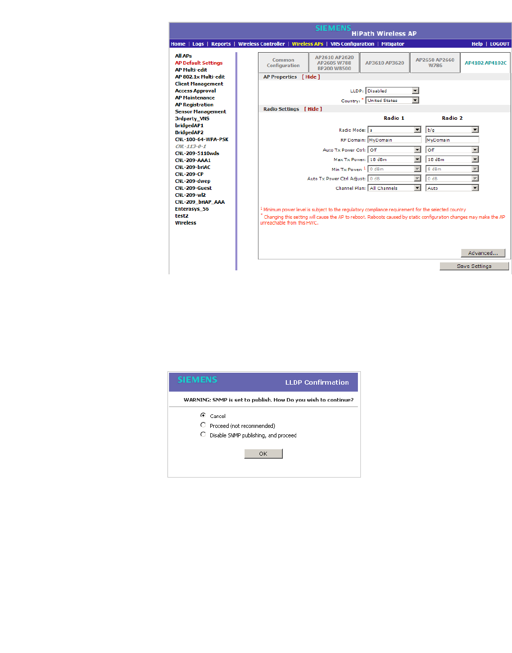
hwc_apstartup.fm
Configuring the Wireless AP
Configuring VLAN tags for Wireless APs
9034530-02, March 2010
HiPath Wireless Controller, Access Points and Convergence Software V7.11, User Guide 205
4. In the AP Properties section, do the following:
•LLDP – Click to Enable or Disable the Wireless AP from broadcasting
LLDP information. This option is disabled by default.
If SNMP is enabled on the HiPath Wireless Controller and you enable
LLDP, the LLDP Confirmation dialog is displayed.
•Select one of the following:
• Proceed (not recommended) – Select this option to enable LLDP
and keep SNMP running, and then click OK.
• Disable SNMP publishing, and proceed – Select this option to
enable LLDP and disable SNMP, and then click OK.
For more information on enabling SNMP, see the HiPath Wireless
Controller, Access Points and Convergence Software Maintenance
Guide.

Configuring the Wireless AP
hwc_apstartup.fm
Configuring VLAN tags for Wireless APs
9034530-02, March 2010
206 HiPath Wireless Controller, Access Points and Convergence Software V7.11, User Guide
• Announcement Interval – If LLDP is enabled, type how often the
Wireless AP advertises its information by sending a new LLDP packet.
This value is measured in seconds.
If there are no changes to the Wireless AP configuration that impact the
LLDP information, the Wireless AP sends a new LLDP packet according
to this schedule.
Note: The Time to Live value cannot be directly edited. The Time to Live
value is calculated as four times the Announcement Interval value.
• Announcement Delay – If LLDP is enabled, type the announcement
delay. This value is measured in seconds. If a change to the Wireless AP
configuration occurs which impacts the LLDP information, the Wireless
AP sends an updated LLDP packet. The announcement delay is the
length of time that delays the new packet delivery. The announcement
delay helps minimize LLDP packet traffic.
• Country – Click the country of operation. This option is only available with
some licenses.
5. In the Radio Settings section, do the following for each radio:
• Radio mode – Click the radio mode you want to enable:
• Radio 1 – off or a.
• Radio 2 – off, b, g, or b/g.
Note: Depending on the radio modes you select, some of the radio settings
may not be available for configuration.
•RF Domain – Type a string that uniquely identifies a group of APs that
cooperate in managing RF channels and transmission power levels. The
maximum length of the string is 16 characters. The RF Domain is used to
identify a group of Wireless APs.
• Auto Tx Power Ctrl – Click to either enable or disable ATPC from the
Auto Tx Power Ctrl drop-down list. ATPC automatically adapts
transmission power signals according to the coverage provided by the
Wireless APs. After a period of time, the system will stabilize itself based
on the RF coverage of your Wireless APs.
•Max Tx Power – Click the appropriate Tx power level from the Max TX
Power drop-down list. The values in the Max TX Power drop-down are
in dBm.

hwc_apstartup.fm
Configuring the Wireless AP
Configuring VLAN tags for Wireless APs
9034530-02, March 2010
HiPath Wireless Controller, Access Points and Convergence Software V7.11, User Guide 207
• Min Tx Power – If ATPC is enabled, click the minimum Tx power level to
which the range of transmit power can be adjusted: 0 to 23 (b/g or b/g/n)
or 24 (a or a/n) dBm. It is recommended to use 0 dBm to not limit the
potential Tx power level range that can be used.
• Auto Tx Power Ctrl Adjust – If ATPC is enabled, click the Tx power level
that can be used to adjust the ATPC power levels that the system has
assigned. It is recommended to use 0 dBm during your initial
configuration. If you have an RF plan that recommends Tx power levels
for each Wireless AP, compare the actual Tx power levels your system
has assigned against the recommended values your RF plan has
provided. Use the Auto Tx Power Ctrl Adjust value to achieve the
recommended values.
• Channel Plan – If ACS is enabled you can define a channel plan for the
Wireless AP. Defining a channel plan allows you to limit which channels
are available for use during an ACS scan. For example, you may want to
avoid using specific channels because of low power, regulatory domain,
or radar interference.
For Radio 1, click one of the following:
• All channels – ACS scans all channels for an operating channel and
returns both DFS and non-DFS channels, if available.
• All Non-DFS Channels – ACS scans all non-DFS channels for an
operating channel. This selection is available when there is at least
one DFS channel supported for the selected country.
•Custom – To configure individual channels from which the ACS will
select an operating channel, click Configure. The Custom Channel
Plan dialog displays. By default, all channels participate in the
channel plan. Click the individual channels you want to include in the
channel plan. To select contiguous channels, use the Shift key. To
select multiple, non-contiguous channels in the list, use the CTRL
key. Click OK to save the configuration.
For Radio 2, click one of the following:
• 3 Channel Plan – ACS will scan the following channels: 1, 6, and 11
in the US, and 1, 7, and 13 in Europe.
• 4 Channel Plan – ACS will scan the following channels: 1, 4, 7, and
11 in the US, and 1, 5, 9, and 13 in Europe.
•Auto – ACS will scan the default channel plan channels: 1, 6, and 11
in the US, and 1, 5, 9, and 13 in Europe.

Configuring the Wireless AP
hwc_apstartup.fm
Configuring VLAN tags for Wireless APs
9034530-02, March 2010
208 HiPath Wireless Controller, Access Points and Convergence Software V7.11, User Guide
•Custom – If you want to configure individual channels from which the
ACS will select an operating channel, click Configure. The Add
Channels dialog is displayed. Click the individual channels you want
to add to the channel plan while pressing the CTRL key, and then click
OK.
6. To modify default access point advanced settings, click Advanced. The
Advanced dialog is displayed.
7. In the Advanced dialog AP Properties section, do the following:
• Poll Timeout – Type the timeout value, in seconds. The Wireless AP
uses this value to trigger re-establishing the link with the HiPath Wireless
Controller if it (Wireless AP) does not get an answer to its polling. The
default value is 10 seconds.
Note: If you are configuring session availability, the Poll Timeout value
should be 1.5 to 2 times of Detect link failure value on AP Properties
screen. For more information, see Section 7.4, “Session availability”, on page
392.
• Telnet Access – Click to Enable or Disable telnet access to the Wireless
AP.
• Maintain client session in event of poll failure – Click to Enable or
Disable (if using a bridged at AP VNS) if the AP should remain active if a
link loss with the controller occurs.This option is enabled by default.
• Restart service in the absence of controller – Click to Enable or
Disable (if using a bridged at AP VNS) to ensure the Wireless APs’ radios
continue providing service if the Wireless AP’s connection to the HiPath
Wireless Controller is lost. If this option is enabled, it allows the Wireless
AP to start a bridged at AP VNS even in the absence of a HiPath Wireless
Controller.
• Use broadcast for disassociation – Click to Enable or Disable if you
want the Wireless AP to use broadcast disassociation when
disconnecting all clients, instead of disassociating each client one by one.
This will affect the behavior of the AP under the following conditions:
•If the Wireless AP is preparing to reboot or to enter one of the special
modes (DRM initial channel selection).
•If a BSSID is deactivated or removed on the Wireless AP.
This option is disabled by default.
8. In the Advanced dialog Radio Settings section, do the following:

hwc_apstartup.fm
Configuring the Wireless AP
Configuring VLAN tags for Wireless APs
9034530-02, March 2010
HiPath Wireless Controller, Access Points and Convergence Software V7.11, User Guide 209
•DTIM – Type the desired DTIM (Delivery Traffic Indication Message)
period — the number of beacon intervals between two DTIM beacons. To
ensure the best client power savings, use a large number. For example,
5. Use a small number to minimize broadcast and multicast delay. The
default value is 5.
• Beacon Period – Type the desired time, in milliseconds, between
beacon transmissions. The default value is 100 milliseconds.
• RTS/CTS – Type the packet size threshold, in bytes, above which the
packet will be preceded by an RTS/CTS (Request to Send/Clear to Send)
handshake. The default value is 2346, which means all packets are sent
without RTS/CTS. Reduce this value only if necessary.
• Frag. Threshold – Type the fragment size threshold, in bytes, above
which the packets will be fragmented by the AP prior to transmission. The
default value is 2346, which means all packets are sent unfragmented.
Reduce this value only if necessary.
• Max % of non-unicast traffic per Beacon period – Enter the maximum
percentage of time that the AP will transmit non-unicast packets
(broadcast and multicast traffic) for each configured Beacon Period. For
each non-unicast packet transmitted, the system calculates the airtime
used by eack packet and drops all packets that exceed the configured
maximum percentage. By restricting non-unicast traffic, you limit the
impact of broadcasts and multicasts on overall system performance.
• Maximum Distance – Enter a value from 100 to 15,000 meters that
identifies the maximum link distance between APs that participate in a
WDS. This value ensures that the acknowledgement of communication
between APs does not exceed the timeout value predefined by the 802.11
standard. The default value is 100 meters. If the link distance between
APs is greater than 100 meters, configure the maximum distance up to
15,000 meters so that the software increases the timeout value
proportionally with the distance between APs.
Do not change the default setting for the radio that provides service to
802.11 clients only.
• Dynamic Channel Selection – Click one of the following:
•Off – Disables DCS.
• Monitor Mode – If traffic or noise levels exceed the configured DCS
thresholds, an alarm is triggered and an information log is generated.
• Active Mode – If traffic or noise levels exceed the configured DCS
thresholds, an alarm is triggered and an information log is generated.
In addition, the Wireless AP will cease operating on the current
channel and ACS is employed to automatically select an alternate
channel for the Wireless AP to operate on.

Configuring the Wireless AP
hwc_apstartup.fm
Configuring VLAN tags for Wireless APs
9034530-02, March 2010
210 HiPath Wireless Controller, Access Points and Convergence Software V7.11, User Guide
• DCS Noise Threshold – If DCS is enabled, type the noise
interference level, measured in dBm, after which ACS will scan for a
new operating channel for the Wireless AP if the threshold is
exceeded.
• DCS Channel Occupancy Threshold – If DCS is enabled, type the
channel utilization level, measured as a percentage, after which ACS
will scan for a new operating channel for the Wireless AP if the
threshold is exceeded.
• DCS Update Period – If DCS is enabled, type the time, measured in
minutes that determines the period during which the Wireless AP
averages the DCS Noise Threshold and DCS Channel Occupancy
Threshold measurements. If either one of these thresholds is
exceeded, then the Wireless AP will trigger ACS.
• Rx Diversity – Cick Best for the best signal from both antennas, or Left
or Right to choose either of the two diversity receiving antennas. The
default and recommended selection is Best. If only one antenna is
connected, use the corresponding Left or Right diversity setting. Do not
use Best if two identical antennas are not used.
• Tx Diversity – Click Alternate for the best signal from both antennas, or
Left or Right to choose either of the two diversity receiving antennas. The
default selection is Alternate that maximizes performance for most
clients. However, some clients may behave oddly with Tx Diversity set to
Alternate. Under those circumstances, it is recommended to use either
Left or Right for Tx Diversity. If only one antenna is connected, use the
corresponding Left or Right diversity setting. Do not use Alternate if two
identical antennas are not used.
•Preamble – Click a preamble type for 11b-specific (CCK) rates: Short,
Long, or Auto. The recommended value is Auto. Click Short if you are
sure that there is no pre-11b AP or a client in the vicinity of this AP. Click
Long if compatibility with pre-11b clients is required.
• Protection Mode – Click a protection mode: None, Auto, or Always.
The default and recommended setting is Auto. Click None if 11b APs and
clients are not expected. Click Always if you expect many 11b-only
clients.
• Protection Rate – Click a protection rate: 1, 2, 5.5, or 11 Mbps. The
default and recommended setting is 11. Only reduce the rate if there are
many 11b clients in the environment or if the deployment has areas with
poor coverage. For example, rates lower than 11 Mbps are required to
ensure coverage.
• Protection Type – Click a protection type: CTS Only or RTS CTS. The
default and recommended setting is CTS Only. Click RTS CTS only if an
11b AP that operates on the same channel is detected in the
neighborhood, or if there are many 11b-only clients in the environment.

hwc_apstartup.fm
Configuring the Wireless AP
Configuring VLAN tags for Wireless APs
9034530-02, March 2010
HiPath Wireless Controller, Access Points and Convergence Software V7.11, User Guide 211
9. In the Advanced dialog Enhanced Rate Control section, do the following:
• Min Basic Rate – For each radio, click the minimum data rate that must
be supported by all stations in a BSS: 1, 2, 5.5, or 11 Mbps for 11b and
11b+11g modes. Click 1, 2, 5.5, 6, 11, 12, or 24 Mbps for 11g-only mode.
Click 6, 12, or 24 Mbps for 11a mode. If necessary, the Max Basic Rate
choices adjust automatically to be higher or equal to the Min Basic Rate.
If both Min Basic Rate and Max Basic Rate are set to an 11g-specific
(OFDM) rate, (for example, 6, 12, or 24 Mbps) all basic rates will be 11g-
specific.
• Max Basic Rate – For each radio, click the maximum data rate that must
be supported by all stations in a BSS: 1, 2, 5.5, or 11 Mbps for 11b and
11b+11g modes. Click 1, 2, 5.5, 6, 11, 12, or 24 Mbps for 11g-only mode.
Click 6, 12, or 24 Mbps for 11a mode. If necessary, the Max Basic Rate
choices adjust automatically to be higher or equal to the Min Basic Rate.
If both Min Basic Rate and Max Basic Rate are set to an 11g-specific
(OFDM) rate, (for example, 6, 12, or 24 Mbps) all basic rates will be 11g-
specific.
• Max Operational Rate – For each radio, click the maximum data rate that
clients can operate at while associated with the AP: 1, 2, 5.5, or 11 Mbps
for 11b-only mode. Click 1, 2, 5.5, 6, 9, 11, 12, 18, 24, 36, 28, or 54 Mbps
for 11b+11g or 11g-only modes. Click 6, 9, 12, 18, 24, 36, 48, or 54 Mbps
for 11a mode. If necessary, the Max Operational Rate choices adjust
automatically to be higher or equal to the Min Basic Rate.
10. In the Advanced dialog No of Retries section, do the following:
• Background BK – For each radio, click the number of retries for the
Background transmission queue. The default value is adaptive (multi-
rate). The recommended setting is adaptive (multi-rate).
• Best Effort BE – For each radio, click the number of retries for the Best
Effort transmission queue. The default value is adaptive (multi-rate).
The recommended setting is adaptive (multi-rate).
•Video VI – For each radio, click the number of retries for the Video
transmission queue. The default value is adaptive (multi-rate). The
recommended setting is adaptive (multi-rate).
•Voice VO – For each radio, click the number of retries for the Voice
transmission queue. The default value is adaptive (multi-rate). The
recommended setting is adaptive (multi-rate).
• Turbo Voice TVO – For each radio, click the number of retries for the
Turbo Voice transmission queue. The default value is adaptive (multi-
rate). The recommended setting is adaptive (multi-rate).
11. Click Close. The Advanced dialog is closed.
12. To save your changes, click Save Settings.

Configuring the Wireless AP
hwc_apstartup.fm
Modifying a Wireless AP’s properties based on a default AP configuration
9034530-02, March 2010
212 HiPath Wireless Controller, Access Points and Convergence Software V7.11, User Guide
4.6 Modifying a Wireless AP’s properties based on a default AP
configuration
If you have a Wireless AP that is already configured with its own settings, but
would like the Wireless AP to be reset to use the system’s default AP settings,
use the Reset to Defaults feature on the AP Properties tab.
To configure a Wireless AP with the system’s default AP settings:
1. From the main menu, click Wireless AP Configuration. The HiPath
Wireless AP screen is displayed.
2. In the Wireless AP list, click the Wireless AP whose properties you want to
modify. The AP Properties tab displays Wireless AP information.
3. To have the Wireless AP inherit the system’s default AP settings, click Reset
to Defaults. A pop-up dialog asking you to confirm the configuration change
is displayed.
4. To confirm resetting the Wireless AP to the default settings, click OK.
Caution: If you reset an AP to defaults, its HWC Search List will be deleted,
regardless of the settings in Common Configuration.
4.7 Modifying the Wireless AP’s default setting using the Copy to Defaults
feature
You can modify the system’s default AP settings by using the Copy to Defaults
feature on the AP Properties tab. This feature allows the properties of an already
configured Wireless AP to become the system’s default Wireless AP settings.
To modify the system’s default AP settings based on an already configured
AP:
1. From the main menu, click Wireless AP Configuration. The HiPath
Wireless AP screen is displayed.
2. In the Wireless AP list, click the Wireless AP whose properties you want to
become the system’s default AP settings. The AP Properties tab is
displayed.
3. If applicable, modify the Wireless AP’s properties. For more information, see
Section 4.4.2, “Configuring a Wireless AP’s properties”, on page 122.
4. To make this Wireless AP’s configuration be the system’s default AP settings,
click Copy to Defaults. A pop-up dialog asking you to confirm the
configuration change is displayed.

hwc_apstartup.fm
Configuring the Wireless AP
Configuring Wireless APs simultaneously
9034530-02, March 2010
HiPath Wireless Controller, Access Points and Convergence Software V7.11, User Guide 213
5. To confirm resetting the system’s default Wireless AP settings, click OK.
4.8 Configuring Wireless APs simultaneously
In addition to configuring Wireless APs individually, you can also configure
multiple Wireless APs simultaneously by using the AP Multi-edit function.
Configuring Wireless APs simultaneously is similar to modifying the system’s
default AP settings or individual Wireless APs.
When selecting which Wireless APs to configure simultaneously, you can use the
following criteria:
•Select the Wireless APs by hardware type
•Select the Wireless APs individually
You can select multiple hardware types and individual Wireless APs by pressing
the Ctrl key and selecting the hardware types and specific Wireless APs.
When you configure multiple Wireless APs using the AP Multi-edit screen, it is
important to note that for some Wireless AP settings to be available for
configuration, other Wireless AP settings must be enabled or configured first.
Note: Only settings and options supported by all of the currently selected
hardware types are available for configuring.
To configure Wireless APs simultaneously:
1. From the main menu, click Wireless AP Configuration. The HiPath
Wireless AP screen is displayed.
2. In the left pane, click AP Multi-edit.
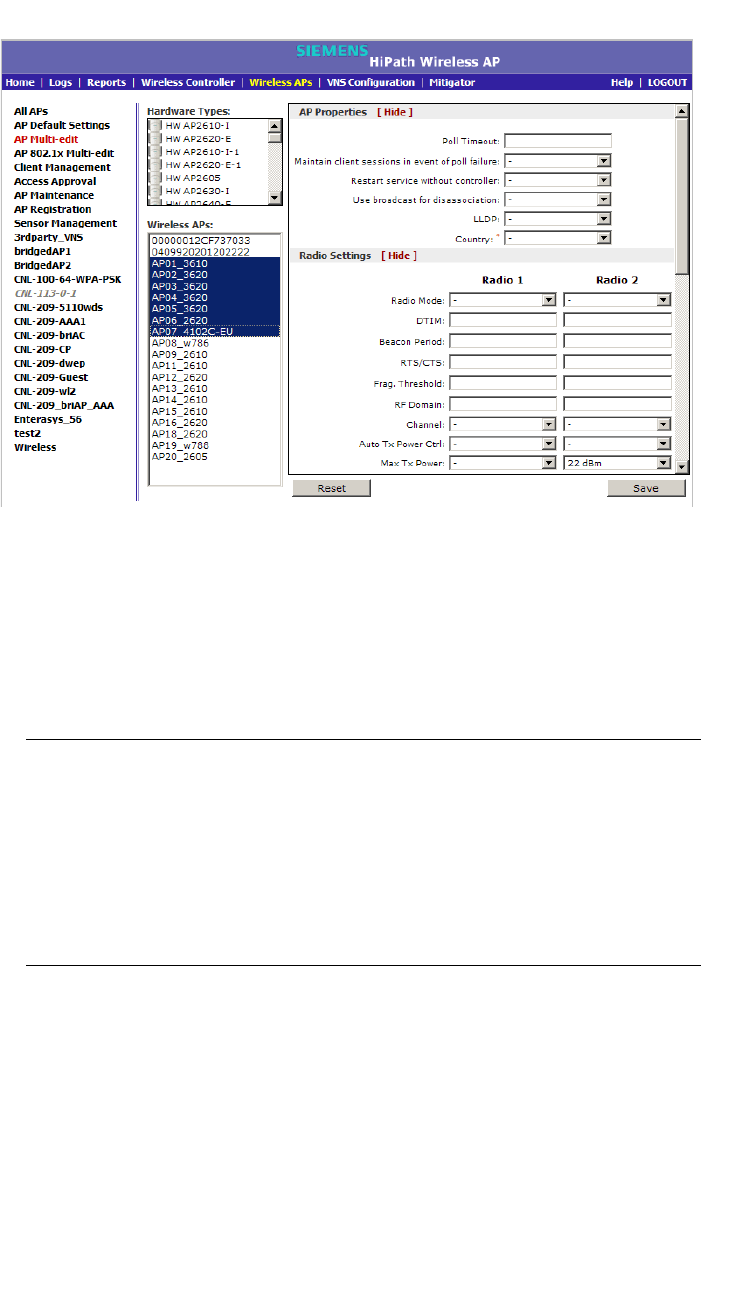
Configuring the Wireless AP
hwc_apstartup.fm
Configuring Wireless APs simultaneously
9034530-02, March 2010
214 HiPath Wireless Controller, Access Points and Convergence Software V7.11, User Guide
3. Do the following:
•In the Hardware Types list, click one or more Wireless AP hardware
types.
•In the Wireless APs list, click one or more Wireless APs to edit. To click
multiple Wireless APs, click the APs from the list while pressing the CTRL
key.
Note: When using the Multi-edit function, any box or option that is not
explicitly modified will not be changed by the update.
The Wireless APs shown in the Wireless APs list can be from any version of
the software. Attributes that are common between software versions are set
on all Wireless APs. Attributes that are not common, are only sent to the AP
versions to which the attributes apply. Attempting to set an attribute that does
not apply for an AP will not abort the multi-edit operation.
4. Modify the configuration of the selected Wireless APs:
• AP Properties – For more information, see Section 4.4.2, “Configuring a
Wireless AP’s properties”, on page 122.
• Radio Settings – For more information, see Section 4.4.5, “Configuring
Wireless AP radio properties”, on page 130.
5. To modify the static configuration of the selected Wireless APs, in the HWC
Search List, click one of the following:

hwc_apstartup.fm
Configuring the Wireless AP
Configuring an AP as a sensor
9034530-02, March 2010
HiPath Wireless Controller, Access Points and Convergence Software V7.11, User Guide 215
• Clear search list – Click to clear previously assigned HiPath Wireless
Controllers that were configured to control this Wireless AP.
• Re-configure search list – Click to assign HiPath Wireless Controllers
to control this Wireless AP.
a) In the Add box, type the IP address of the HiPath Wireless Controller
that will control this Wireless AP.
b) Click Add. The IP address is added to the list.
c) Repeat to add additional HiPath Wireless Controllers.
d) Click Up and Down to modify the order of the HiPath Wireless
Controllers. The maximum is three HiPath Wireless Controllers.
The Wireless AP attempts to connect to the IP addresses in the order in which
they are listed. The Wireless AP is successful when it finds a HiPath Wireless
Controller that will allow it to register.
This feature allows the Wireless AP to bypass the discovery process. If the
HWC Search List is not populated, the Wireless AP will use SLP to discover
a HiPath Wireless Controller. For the initial Wireless AP deployment, it is
necessary to use one of the described options in Section 4.2, “Discovery and
registration overview”, on page 97.
6. To modify the WLAN assignments of the selected Wireless APs, in the WLAN
Assignment Option drop-down list, click one of the following:
• Clear WLAN list – Click to clear previously assigned WLAN services of
the Wireless APs.
• Re-configure WLAN list – Click to assign WLAN services to the Wireless
APs.
•In the Radio 1 and Radio 2 columns, select the Wireless AP radios
that you want to assign for each WLAN service.
7. To save your changes, click Save.
4.9 Configuring an AP as a sensor
Only the HiPath Wireless AP 2610/2620 and the Wireless 802.11n AP can be
configured as sensors.
A Wireless AP that is configured as a sensor performs scanning services and
relays information to HiPath Wireless Manager HiGuard. When an AP is
Approved as Sensor:
•The AP severs its connection to the HiPath Wireless Controller
•The AP registers with HiPath Wireless Manager HiGuard
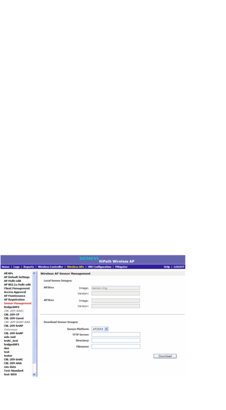
Configuring the Wireless AP
hwc_apstartup.fm
Configuring an AP as a sensor
9034530-02, March 2010
216 HiPath Wireless Controller, Access Points and Convergence Software V7.11, User Guide
•The AP performs scanning services
•The AP no longer performs RF services for the HiPath Wireless Controller
When an AP is operating as a sensor, it has no interaction with the HiPath
Wireless Controller, and it does not perform like an AP: it does not allow devices
to associate to it and traffic is not forwarded through it. An AP operating as a
sensor is managed by HiPath Wireless Manager HiGuard. The HiPath Wireless
Manager HiGuard’s sensor domain license (SDL) limit governs the number of
sensors the customer can have.
When an AP is configured as a sensor, the AP’s current configuration is retained
in the controller database. If the sensor is later configured back to perform RF
services, its previous configuration data is reassigned to it. For more information,
see the HiPath Wireless Manager User Guide and the HiPath Wireless Manager
HiGuard User Guide.
Before APs can be configured as sensors, you must first configure the Sensor
Management values for the HiPath Wireless Controller:
•TFTP server IP address
•Path to 26xx image
•Path to 36xx image
To configure Sensor Management values for the HiPath Wireless
Controller:
1. From the main menu, click Wireless AP Configuration. The HiPath
Wireless AP screen is displayed.
2. In the left pane, click Sensor Management. The Wireless AP Sensor
Management screen is displayed.
3. Type the following:

hwc_apstartup.fm
Configuring the Wireless AP
Performing Wireless AP software maintenance
9034530-02, March 2010
HiPath Wireless Controller, Access Points and Convergence Software V7.11, User Guide 217
• TFTP Server – The IP address of the TFTP server the AP is to retrieve
the sensor image file from.
• Path to 26xx Image – The filename and location of the 26xx sensor
image.
• Path to 36xx Image – The filename and location of the 36xx sensor
image.
Note: The Path to 36xx image box is only available if the HiPath Wireless
Controller is managed by the HiPath Wireless Manager V2R3.
4. To save your changes, click Save.
4.10 Performing Wireless AP software maintenance
Periodically, the software used by the Wireless APs is altered for reasons of
upgrade or security. The new version of the AP software is installed from the
HiPath Wireless Controller.
The software for each Wireless AP can be uploaded either immediately, or the
next time the Wireless AP connects. Part of the Wireless AP boot sequence is to
seek and install its software from the HiPath Wireless Controller.
Most of the properties of each radio on a Wireless AP can be modified without
requiring a reboot of the AP.
The Wireless AP keeps a backup copy of its software image. When a software
upgrade is sent to the Wireless AP, the upgrade becomes the Wireless AP's
current image and the previous image becomes the backup. In the event of failure
of the current image, the Wireless AP will run the backup image.
Note: The HiPath Wireless Controller does not ship with sensor software. Sensor
software must be installed on a TFTP server.
To maintain the list of current Wireless AP software images:
1. From the main menu, click Wireless AP Configuration. The Wireless AP
Configuration screen is displayed.
2. In the left pane, click AP Maintenance. The AP Maintenance tab is
displayed.
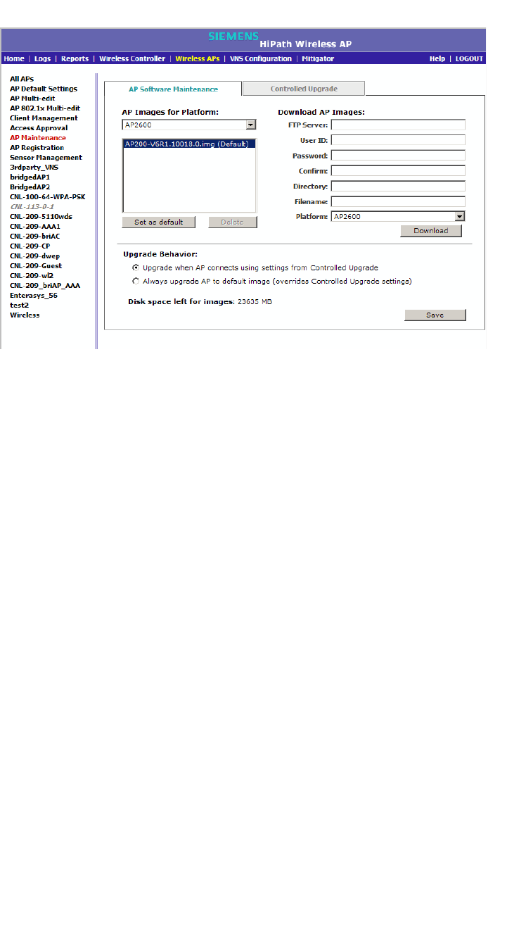
Configuring the Wireless AP
hwc_apstartup.fm
Performing Wireless AP software maintenance
9034530-02, March 2010
218 HiPath Wireless Controller, Access Points and Convergence Software V7.11, User Guide
3. In the AP Images for Platform drop-down list, click the appropriate platform.
4. To select an image to be the default image for a software upgrade, click it in
the list, and then click Set as default.
5. In the Upgrade Behavior section, select one of the following:
• Upgrade when AP connects using settings from Controlled Upgrade
– The Controlled Upgrade tab is displayed. Controlled upgrade allows
you to individually select and control the state of an AP image upgrade:
which APs to upgrade, when to upgrade, how to upgrade, and to which
image the upgrade or downgrade should be done. Administrators decide
on the levels of software releases that the equipment should be running.
• Always upgrade AP to default image (overrides Controlled Upgrade
settings) – Selected by default. Allows for the selection of a default
revision level (firmware image) for all APs in the domain. As the AP
registers with the controller, the firmware version is verified. If it does not
match the same value as defined for the default-image, the AP is
automatically requested to upgrade to the default-image.
6. To save your changes, click Save.
To delete a Wireless AP software image:
1. From the main menu, click Wireless AP Configuration. The Wireless AP
Configuration screen is displayed.
2. In the left pane, click AP Maintenance. The AP Software Maintenance tab
is displayed.
3. In the AP Images for Platform drop-down list, click the appropriate platform.

hwc_apstartup.fm
Configuring the Wireless AP
Performing Wireless AP software maintenance
9034530-02, March 2010
HiPath Wireless Controller, Access Points and Convergence Software V7.11, User Guide 219
4. In the AP Images list, click the image you want to delete.
5. Click Delete. The image is deleted.
To download a new Wireless AP software image:
1. From the main menu, click Wireless AP Configuration. The Wireless AP
Configuration screen is displayed.
2. In the left pane, click AP Maintenance. The AP Software Maintenance tab
is displayed.
3. In the Download AP Images list, type the following:
•FTP Server – The IP of the FTP server to retrieve the image file from.
•User ID – The user ID that the controller should use when it attempts to
log in to the FTP server.
• Password – The corresponding password for the user ID.
• Confirm – The corresponding password for the user ID to confirm it was
typed correctly.
•Directory – The directory on the server in which the image file that is to
be retrieved is stored.
• Filename – The name of the image file to retrieve.
•Platform – The AP hardware type to which the image applies. The are
several types of AP and they require different images.
4. Click Download. The new software image is downloaded.
To define parameters for a Wireless AP controlled software upgrade:
1. From the main menu, click Wireless AP Configuration. The Wireless AP
Configuration screen is displayed.
2. In the left pane, click AP Maintenance. The AP Software Maintenance tab
is displayed.
3. Click the Controlled Upgrade tab.
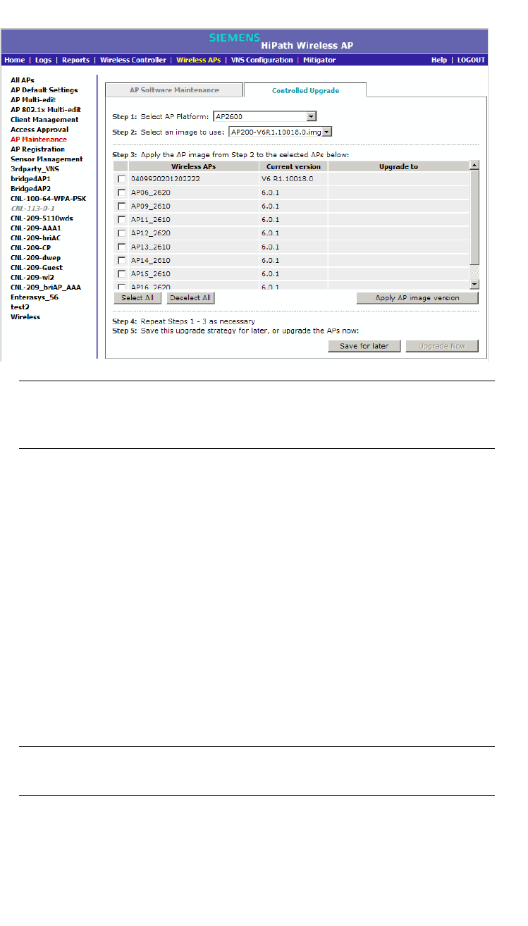
Configuring the Wireless AP
hwc_apstartup.fm
Performing Wireless AP software maintenance
9034530-02, March 2010
220 HiPath Wireless Controller, Access Points and Convergence Software V7.11, User Guide
Note: The Controlled Upgrade tab is displayed only when the Upgrade
Behavior is set to Upgrade when AP connects using settings from
Controlled Upgrade on the AP Software Maintenance tab.
4. In the Select AP Platform drop-down list, click the type of AP you want to
upgrade.
5. In the Select an image to use drop-down list, click the software image you
want to use for the upgrade.
6. In the list of registered Wireless APs, select the checkbox for each Wireless
AP to be upgraded with the selected software image.
7. Click Apply AP image version. The selected software image is displayed in
the Upgrade To column of the list.
8. To save the software upgrade strategy to be run later, click Save for later.
9. To run the software upgrade immediately, click Upgrade Now. The selected
Wireless AP reboots, and the new software version is loaded.
Note: The Always upgrade AP to default image checkbox on the AP
Software Maintenance tab overrides the Controlled Upgrade settings.

hwc_vnsintro.fm
9034530-02, March 2010
HiPath Wireless Controller, Access Points and Convergence Software V7.11, User Guide 221
Virtual Network Services concepts
VNS overview
5 Virtual Network Services concepts
This chapter introduces and describes the concept of Virtual Network Services
(VNS), including:
•VNS overview
•Setting up a VNS checklist
•NAC integration with HiPath WLAN
•Wireless AP assignment to WLAN Services
•Authentication for a VNS
•Filtering
•Multicast traffic
•Data protection — WEP and WPA
•QoS Policy
•Flexible Client Access (FCA)
5.1 VNS overview
Starting with Release V7.0, the VNS concept is factored into two main
components:
•WLAN Service - which defines the radio/RF attributes of a service (e.g. its
SSID), its privacy and authentication settings and the QoS attributes.
•User Policy - which defines the topology (typically a VLAN), filter rules, and
Class of Service applied to the traffic of a station.
Rather than being a collection of operational entities, a VNS becomes simply the
binding between the WLAN service and the user policy for default operation. The
policy assignment ensures that the correct topology and traffic behavior are
applied to a user regardless/independent of the SSID.
This new representation model extends provisioning functionality by allowing for:
•Multiple WLAN services associated to the same Topology (VLAN
Mapping)
•Overlapped Role/Policy Assignment
•User to policy association independent of access SSID
•Separation of L2/L3 representations

Virtual Network Services concepts
hwc_vnsintro.fm
VNS overview
9034530-02, March 2010
222 HiPath Wireless Controller, Access Points and Convergence Software V7.11, User Guide
•Topology now allow for VLANs without L3 presence
Note: The concepts introduced in V7.0 facilitate the integration between HiPath.
WLAN and the Enterasys Policy Manager. However, discussion about their
integration, the communication between the two, provisioning model, and so on
are not part of this document.
The configurable high-level distinct umbrella elements of a VNS are:
•Topology
•Policy
•WLAN Services
It is important to note, however, that Topologies are associated with Policies,
which makes configuration of a VNS association between a WLAN Service and
a Policy (that inturn defines a Policy).
5.1.1 Topology
A Topology is represented by the configurable networking parameters and
options which define the HiPath Wireless Controller and APs’ interactions with the
other networking elements. The main attributes of a topology are:
•Name
•Mode, which can be one of the following:
– Routed
– Bridge Traffic Locally at AP
– Bridge Traffic Locally at HWC
•VLAN ID
•Tagged or untagged
•Port attachments to the network for the HiPath Wireless Controller only. This
is not required for Routed or Bridge Traffic Locally at AP topologies, but it is
required for Bridge Traffic Local at HWC.
•Interface (L3) definition, i.e., the IP address assigned to the HiPath Wireless
Controller’s interface attached to the network described by a given topology
(optional)
•Topologu type, which is the intuitive description of traffic forwarding
mechanisms. The options are:
– “Physical,” describing an Ethernet port

hwc_vnsintro.fm
Virtual Network Services concepts
VNS overview
9034530-02, March 2010
HiPath Wireless Controller, Access Points and Convergence Software V7.11, User Guide 223
– “Admin,” meaning this is the native topology of the HiPath Wireless
Controller management port
– “Routed,” describing the L3 stub network segments
– “Bridged at Controller,” which allows L2 forwarding between the wireless
clients and core network, or
– “Bridged at AP,” which is implemented by local bridging done at the APs
themselves.
•Exception Filters (available only if an L3 presence has been defined)
(As a matter of implementation, a topology that does not have a layer 3
presence (IP Address) assigned to it will have a “deny all” exception filter
attached to it. This filter will not be configurable or even visible to the
administrator.)
•Certificates (only allowed if an L3 presence has been defined)
•Multicast filters
The main Topologies GUI includes a field for configuring the internal VLAN. This
field's default value is 1 as in previous releases. This value can also be changed
to match the existing network configuration.
5.1.2 Policy
In general, a Policy Profile is defined as a collection of attributes and rules to be
applied to the traffic of ports and stations. The Enterasys Policy Manager's policy
profile permits the definition of default VLAN and Class of Service assignments
that can be used when other more specific policy assignment mechanisms (that
is, policy rule matches) do not apply.
On HiPath platforms, the Policy defines the binding of Default Topology, Default
Rate Profiles, and Default filter rules.
In general, the Class of Service refers to a set of attributes that define the
importance of a frame, while forwarded through the network ,relative to other
packets, and to the maximum throughput per time unit that a station or port
assigned to the policy is permitted. The Class of Service defines actions to be
taken when rate limits are exceeded.
On the HiPath Wireless Controller, the configuration of the CoS is part of WLAN
Service while the Rate Control and Filtering are part of Policy definition. The
actions allowed by the HiPath implementation are: allow or drop.
Policies don't need to be fully specified; Unspecified attributes are retained by the
user or inherited from Global Policy definitions

Virtual Network Services concepts
hwc_vnsintro.fm
VNS overview
9034530-02, March 2010
224 HiPath Wireless Controller, Access Points and Convergence Software V7.11, User Guide
Default Global Policy definitions provide a placeholder for completion of
incomplete policies for initial default assignment. If a policy is defined as Default
for a particular VNS, incomplete (or NO-CHANGE) attributes are inherited from
Default Global Policy Definitions
Default Global Policy parameter values are:
•Topology = Bridged at AP
•Filter = Deny All
•Rate Control = “Unlimited”
Note that you can change these Global Policy parameters from their default
values during configuration.
5.1.3 WLAN Service
A WLAN Service represents all the RF, authentication and QoS attributes of a
wireless access service. The WLAN Service can be of three basic types:
•Standard - A conventional service. Only APs running HiPath Wireless
software can be part of this WLAN Service. This type of service is usable as
a Bridged @ Controller, Bridged @ AP or Routed topologies. This type of
service provides access for mobile stations. Therefore, policies can be
assigned to this type of WLAN service to create a VNS.
•Third Party AP - A Wireless Service offered by third party APs. This type of
service provides access for mobile stations. Therefore policies can be
assigned to this type of WLAN service to create a VNS. Note that the
requirement is to run the deployment of the third party topology using the
controller as the routing gateway for the segments served by third party APs.
•WDS - This represents a group of APs organized into an interconnection
hierarchy for purposes of providing a Wireless Distribution Service. This type
of service is in essence a wireless trunking service rather than a service that
provides access for stations. As such, this type of service cannot have
policies attached to it.
APs from a WDS group still can provide access for mobile clients via standard
service.
For V7.0 the components of the WLAN Service map more or less completely to
the corresponding components of a VNS in V7.0. The exception is that WLAN
Services are not classified as SSID-based or AAA-based, as VNSs were in
releases prior to V6Rx. Instead, the administrator makes an explicit choice of the
type of authentication to use on the WLAN Service. If his choice of authentication
option conflicts with any of his other authentication or privacy choices the WLAN
Service cannot be enabled.
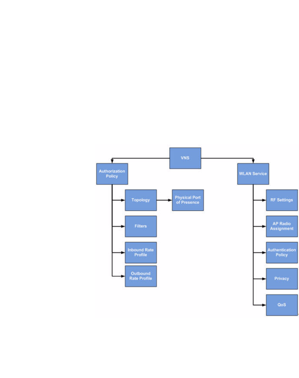
hwc_vnsintro.fm
Virtual Network Services concepts
VNS overview
9034530-02, March 2010
HiPath Wireless Controller, Access Points and Convergence Software V7.11, User Guide 225
5.1.4 New VNS definition
The central objective of the newly defined (in V7.0) VNS is to allow for more
configuration flexibility by separating reusable components (such as topology,
policies, and so forth) and to allow for integration with the Enterasys Policy
Manager.
Figure 11 on page 225 shows the breakdown of a VNS into its primary
components. The direction of the arrows in this diagram indicates the direction of
a dependency.
The VNS is being split into two main entities:
1. WLAN Service – This represents the 802.11 network access service offered
by the HWC and its APs.
2. Authorization Policy – A policy that determines how the traffic of users
accessing the wired network through the WLAN service. An authorization
policy is made of several components.
Figure 11 New VNS definition

Virtual Network Services concepts
hwc_vnsintro.fm
VNS overview
9034530-02, March 2010
226 HiPath Wireless Controller, Access Points and Convergence Software V7.11, User Guide
Breaking the VNS into two main parts, permits a VNS to be created from
components that were defined at different times. For example the HWC can ship
with predefined WLAN Services that are created by the development team. At a
later date a policy can be defined on the HWC (by the administrator or Policy
Manager) and combined with the WLAN Service to create a functional SSID.
In Release V7.0 the new concepts introduced provide new capabilities such as:
•The ability to share an HWC physical port between 3rd party AP VNS and
other types of VNS so long as the VNSs are on different VLANs. Since many
HWC implementations have only 2 physical ports, this allows those
implementations to offer support for 3rd party APs in conjunction with
standard VNSs.
•The ability to have Bridged @ Controller VNSs that do not have a layer 3
presence (IP address). This greatly simplifies “Out of the box” deployments in
which the HWC is only required to function as a layer 2 device.
•The ability to assign separate inbound and outbound rate limits on a per
station basis. These rate limits will apply at the AP and the HWC
•The ability to assign stations to VLANs on a per station basis. All HiPath APs
and controllers running V7.0 software will be able to perform per station
VLAN.
•Simplification of VNS RADIUS server configuration through the migration of
various RADIUS server settings to the global RADIUS server definition.
•Support for allowing Policy Manager to define and manage policies that
specify VLAN assignment, rate limits and filters
•Support for allowing Policy Manager to create VNS by defining policies and
attaching them to WLAN Services
•Support for “Branch Captive Portal”. This feature allows the administrator to
configure any desired type of HWC Captive portal authentication for a WLAN
Service while allowing the APs to locally bridge the payload traffic of
authenticated stations.
•Workflow improvements for defining VNS and their components. One
example of such an improvement is the ability to define topologies, policies
and rate profiles globally and which can then be reused to define many
different services.
•The ability to have multiple WLAN Services use the same VLAN topology. An
administrator can now design his network so that users accessing it from
different SSIDs can share the same physical segment. Different users on the
same segment can be subject to different policies. Support for administrator-
configurable multicast and broadcast rate limiting at the AP. The more flexible
approach to handling network topologies introduced by this feature could lead
to reduced radio capacity without this enhancement being implemented.

hwc_vnsintro.fm
Virtual Network Services concepts
VNS overview
9034530-02, March 2010
HiPath Wireless Controller, Access Points and Convergence Software V7.11, User Guide 227
•Removal of the distinction between AAA and SSID-based VNS. Instead of
this being an explicit attribute that cannot be changed once set, the HWC will
determine from the WLAN Service privacy and authentication settings
whether EAP or Captive portal is required, and will ensure that the
administrator cannot save a configuration that has incomplete or
incompatible RADIUS options. The administrator can change these privacy
and authentication settings pretty much at any time without having to delete
and recreate the VNS. Changing privacy and authentication settings will
cause the sessions of stations on the VNS to be terminated.
•Automatic synchronization of VNS and session information when fast failover
is enabled.
•The HWC UI for managing ports and topologies has moved in the direction of
a true L2-L3 separation.

Virtual Network Services concepts
hwc_vnsintro.fm
Setting up a VNS checklist
9034530-02, March 2010
228 HiPath Wireless Controller, Access Points and Convergence Software V7.11, User Guide
5.2 Setting up a VNS checklist
When you set up a VNS on the HiPath Wireless Controller, you are defining a
topology, policies, and WLAN services for a group of wireless device users.
The checklist suggested in this section is focused on strictly necessary
parameters and selections an administrator has to consider. Proper full contexts
(such as topology, policy, WLAN services) are further described in Chapter 6,
“Configuring a VNS”.
The HiPath Wireless Controller provides the option to define a topology as locally
bridged to a VLAN at the controller. To support that configuration, you must define
which VLAN ID should be used. The network port on which the VLAN is assigned
must be configured on the switch, and the corresponding HiPath Wireless
Controller port must match the correct configuration. With this configuration, it is
possible that the controller is not involved in the IP address assignment for user
addresses. Instead, the IP addresses for users are assigned directly by the
DHCP infrastructure that services the VLAN.
Note: In a VLAN-bridged topology, the default configuration dictates that the
controller is not the DHCP server for that segment. However, DHCP services can
selectively be enabled, including DHCP Relay, allowing you to use the controller
to become the default DHCP server for the VLAN, if applicable.
Before defining a VNS, the following properties must be determined across
topology, policy, and WLAN services:
•A user access plan for both individual users and user groups.
•The RADIUS attribute values that support the user access plan.
•The location and identity of the Wireless APs that will be used on the VNS.
•The routing mechanism to be used on the associated topology.
•For tunneled configurations mostly, the network addresses that the topology
will use.
•A bridge traffic locally at the HWC topology optionally needs the specification
of the IP address for the controller's own interface point on that VLAN.
Alternatively, other modes for topology can be used (bridged at AP, routed,
3rd Part AP).
In addition, if you elect to have the controller operate as the default DHCP
server for the VLAN, the corresponding IP subnet for that subnet must also
be specified.
•The type of authentication for wireless device users on the associated WLAN
service mapped to the desired VNS.

hwc_vnsintro.fm
Virtual Network Services concepts
Setting up a VNS checklist
9034530-02, March 2010
HiPath Wireless Controller, Access Points and Convergence Software V7.11, User Guide 229
•Proper definition and selection of the user Policy would define the filters to be
applied to the users and user groups in order to control network access.
•The quality of service (QoS) definition is part of the WLAN Services
requirements.
•The privacy mechanisms that should be employed between the Wireless APs
and the wireless devices are also configurable at the level of WLAN services.
•Classification list for traffic priority. For example, whether the VNS is to be
used for voice traffic and if voice traffic is to be given priority.
User access plan
The user access plan should analyze the enterprise network and identify which
users should have access to which areas of the network. What areas of the
network should be separated? Which users can go out to the World Wide Web?
The HiPath Wireless Controller, Access Points and Convergence Software
system relies on authenticating users via a RADIUS server (or other
authentication server). To make use of this feature, an authentication server on
the network is required. Make sure that the server's database of registered users,
with login identification and passwords, is current.
In the case of certificate-based installations, you must ensure that the proper user
certificate profiles are setup on the RADIUS server and mobile user.
Note: Deploying Controller, Access Points and Convergence Software without a
RADIUS server (and without authentication of users on the network) is also
possible.
The user access plan should also identify the user groups in your enterprise, and
the business structure of the enterprise network, such as:
•Department (such as Engineering, Sales, Finance)
•Role (such as student, teacher, library user)
•Status (such as guest, administration, technician)
For each user group, you should set up a filter ID attribute in the RADIUS server,
and then associate each user in the RADIUS server to at least one filter ID name.
You can define specific filtering rules, by filter ID attribute, that will be applied to
user groups to control network access. Filtering is applied by the controller. The
controller checks if there is a Policy with a matching name (Filter ID = Policy
name) and applies the set of filter rules from that policy to the session.
Filter ID assignments is a configuration option, and not a requirement to setup per
user filter ID definitions. If a filter is not returned as an attribute in the RADIUS
server’s confirmation (Access-Accept packet) for a particular user, the controller
uses the default filter policy as the applicable filter set.

Virtual Network Services concepts
hwc_vnsintro.fm
NAC integration with HiPath WLAN
9034530-02, March 2010
230 HiPath Wireless Controller, Access Points and Convergence Software V7.11, User Guide
5.3 NAC integration with HiPath WLAN
HiPath WLAN supports integration with a NAC (Network Admission Control)
Gateway. The NAC Gateway can provide your network with authentication,
registration, assessment, remediation, and access control for mobile users.
NAC Gateway integration with HiPath WLAN supports SSID VNSs when used in
conjunction with MAC-based external captive portal authentication.
The following illustration depicts the topology and workflow relationship between
HiPath WLAN that is configured for external captive portal and a NAC Gateway.
For more information, see Section 6.4.1, “Creating a NAC VNS using the VNS
wizard”, on page 259.
Note: The following illustration depicts the workflow for a network environment in
which the NAC Gateway is configured to use a RADIUS server. With this
configuration, the NAC Gateway acts like a RADIUS proxy server. An alternative
is to configure the NAC Gateway to perform MAC-based authentication itself,
using its own database of MAC addresses and permissions.
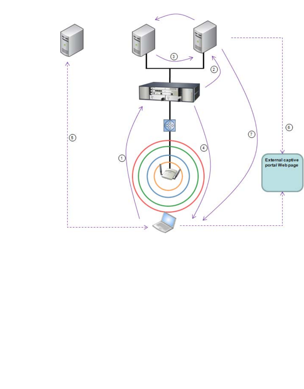
hwc_vnsintro.fm
Virtual Network Services concepts
NAC integration with HiPath WLAN
9034530-02, March 2010
HiPath Wireless Controller, Access Points and Convergence Software V7.11, User Guide 231
Figure 12 HiPath WLAN and NAC integration with external captive portal
authentication
Step 1
•The client laptop connects to the Wireless AP.
•The Wireless AP determines that authentication is required, and sends an
association request to the HiPath Wireless Controller.
Step 2
•The HiPath Wireless Controller forwards to the NAC Gateway an
access-request message for the client laptop, which is identified by its MAC
address.
•The NAC Gateway forwards the access-request to the RADIUS server. The
NAC Gateway acts like a RADIUS proxy server.
DCHP
RADIUS NAC
HiPath
Wireless
Controller
Wireless AP

Virtual Network Services concepts
hwc_vnsintro.fm
NAC integration with HiPath WLAN
9034530-02, March 2010
232 HiPath Wireless Controller, Access Points and Convergence Software V7.11, User Guide
Step 3
•The RADIUS server evaluates the access-request and sends an
Access-Accept message back to the NAC.
•The NAC receives the access-accept packet. Using its local database, the
NAC determines the correct policy to apply to this client laptop and updates
the access-accept packet with the policy assignment. The updated
Access-Accept message is forwarded to the HiPath Wireless Controller and
Wireless AP.
Step 4
The HiPath Wireless Controller and Wireless AP apply policy against the client
laptop accordingly. The HiPath Wireless Controller assigns a set of filters to the
client laptop’s session and the Wireless AP allows the client laptop access to the
network.
Step 5
The client laptop interacts with a DHCP server to obtain an IP address.
Step 6
•Eventually the client laptop uses its Web browser to access a Website.
•The HiPath Wireless Controller determines that the target Website is blocked
and that the client laptop still requires authentication.
•The HiPath Wireless Controller sends an HTTP redirect to the client laptop’s
browser. The redirect sends the browser to the Web server on the NAC
Gateway.
•The NAC displays an appropriate Web page in the client laptop’s browser.
The contents of the page depend on the current policy assignment
(enterprise, remediation, assessing, quarantine, or unregistered) for the MAC
address.
Step 7
•When the NAC determines that the client laptop is ready for a different policy
assignment, it sends a ‘disconnect message’ (RFC 3576) to the HiPath
Wireless Controller.
•When the HiPath Wireless Controller receives the ‘disconnect message’ sent
by the NAC, the HiPath Wireless Controller terminates the session for the
client laptop.
•The HiPath Wireless Controller forwards the command to terminate the client
laptop’s session to the Wireless AP, which disconnects the client laptop.

hwc_vnsintro.fm
Virtual Network Services concepts
Wireless AP assignment to WLAN Services
9034530-02, March 2010
HiPath Wireless Controller, Access Points and Convergence Software V7.11, User Guide 233
5.4 Wireless AP assignment to WLAN Services
The second step in setting up a VNS is to assign Wireless APs to a VNS through
the associated WLAN Services. From the Wireless APs box of the WLAN
Services tab, you assign APs to a WLAN Service and SSID definitions.
Once you have assigned a Wireless AP Radio to eight WLAN Services/VNSs, it
will not appear in the list for another WLAN Service setup. Each Radio can
support up to eight WLAN Services (16 per AP). Each AP can be assigned to any
of the WLAN Services defined within the system. The HiPath Wireless Controller
can support the following active WLAN Services/VNSs:
•C5110 – Up to 128
•C4110 – Up to 64
•C2400 – Up to 64
•C20 – Up to 8
•C20N – Up to 8
•CRBT8210 – Up to 16
•CRBT8110 – Up to 8
5.5 Authentication for a VNS
The authentication mechanism is specified at the WLAN Services level. In
addition, all WLAN Service definitions can include authorization by Media Access
Control (MAC) address. Authorization by MAC address provides a method of
access control for a mobile user as it associates with the Wireless AP based on
the device's MAC address.
The HiPath Wireless Controller offers several authentication options.
• Captive Portal – Captive Portal redirects the http clients (Web browsers) to
a Web page. This Web page is a login page, where users enter their
authentication information. This authentication method offers the following
Captive Portal options:
–Internal Captive Portal –The HiPath Wireless Controller uses its built-in
Web server and Web page to accept authentication data. This Web page
can be customized using the HiPath Wireless Assistant to present a web
login page where the user can enter credentials (user ID and password)
which are being used in the authentication process.
Note: The internal Captive Portal does not substitute for an external
RADIUS server. A RADIUS server is still needed. The internal Captive
Portal within the HiPath Wireless Controller displays the Web page to

Virtual Network Services concepts
hwc_vnsintro.fm
Authentication for a VNS
9034530-02, March 2010
234 HiPath Wireless Controller, Access Points and Convergence Software V7.11, User Guide
enable users to supply their user name and password. The user name
and password are sent to the configured RADIUS server for
authentication.
–External Captive Portal – External Captive Portal can be classified
under the following two categories:
– External Captive Portal with Internal Authentication – After an
external server displays the Captive Portal Web page, the HiPath
Wireless Controller carries out the authentication and implements
policy.
– External Captive Portal with External Authentication — After an
external server displays the Captive Portal Web page and carries out
the authentication, the HiPath Wireless Controller implements policy.
–GuestPortal – A GuestPortal provides wireless device users with
temporary guest network services. A GuestPortal is serviced by a
GuestPortal-dedicated WLAN Service. For more information, see Section
6.5, “Working with a GuestPortal VNS”, on page 285.
–Guest Splash – Guest Splash provides minimal authorization. Login
information is not required when the user is re-directed to the
authorization Web page. The user is only required to select a button and
authorization is approved. This typically could be used where the user is
expected to read and accept some terms and conditions before being
granted network access.
• MAC-based authentication – The RADIUS server authorizes the client
device on the basis of its MAC address. After MAC-based authorization, an
authorized client can go through the selected authentication method for the
applied WLAN service (Captive Portal or 802.1x). If the client device fails the
authentication, the controller will inform the Wireless AP to disassociate the
client device.
MAC-based authentication enables network access to be restricted to
specific devices by MAC address. In addition to the other types of
authentication, when MAC-based authentication is employed, the HiPath
Wireless Controller queries a RADIUS server to determine if the wireless
client's MAC address is authorized to access the network.
• 802.1x authentication – The RADIUS server typically authenticates the
client device on the basis of a certificate. After the client device is
authenticated, it can optionally (if so configured) also go through the Captive
Portal authentication. If the client device fails the Captive Portal
authentication, the controller will inform the Wireless AP to disassociate the
client device.

hwc_vnsintro.fm
Virtual Network Services concepts
Authentication for a VNS
9034530-02, March 2010
HiPath Wireless Controller, Access Points and Convergence Software V7.11, User Guide 235
If a specific filter ID is not defined or returned by the access-accept packet
operation, the HiPath Wireless Controller assigns the VNS' default policy for
authenticated users.
5.5.1 Authentication with Captive Portal
Four authentication types are supported for Captive Portal authentication:
•Password Authentication Protocol (PAP)
•Challenge Handshake Authentication Protocol (CHAP)
•Windows-specific version of CHAP (MS CHAP)
•MS CHAP v2 (Windows-specific version of CHAP, version 2)
For Captive Portal authentication, the RADIUS server must support the selected
authentication type: PAP, CHAP (RFC2484), MS-CHAP (RFC2433), or MS-
CHAPv2 (RFC2759).
5.5.2 Authentication with 802.1x and WPA
If the applied WLAN Service is configured with WPA privacy, the wireless device
user requesting network access must first be authenticated. The wireless
device's client utility must support 802.1x. The user's request for network access
along with login identification or a user profile is forwarded by the HiPath Wireless
Controller to a RADIUS server. The HiPath Wireless Controller, Access Points
and Convergence Software system supports the following authentication types:
• Extensible Authentication Protocol - Transport Layer Security (EAP-
TLS) – Relies on client-side and server-side certificates to perform
authentication. Can be used to dynamically generate a Pairwise Master Key
for encryption.
• Extensible Authentication Protocol with Tunneled Transport Layer
Security (EAP-TTLS) – Relies on mutual authentication of client and server
through an encrypted tunnel. Unlike EAP-TLS, it requires only server-side
certificates. The client uses PAP, CHAP, or MS-CHAPv2 for authentication.
• Protected Extensible Authentication Protocol (PEAP) – Is an
authentication protocol similar to TTLS in its use of server side certificates for
server authentication and privacy and its support for a variety of user
authentication mechanisms.
For EAP-SIM and EAP-FAST, the RADIUS server must support RADIUS
extensions (RFC2869).

Virtual Network Services concepts
hwc_vnsintro.fm
Filtering
9034530-02, March 2010
236 HiPath Wireless Controller, Access Points and Convergence Software V7.11, User Guide
Until the access-accept packet is received from the RADIUS server for a specific
user, the user is kept in an unauthenticated state. 802.1x rules dictate no other
packets other than EAP are allowed to traverse between the AP and the HiPath
Wireless Controller until authentication completes. Once authentication is
completed (access-accept packet is received), the user's client is then allowed to
proceed with IP services, which typically implies the request of an IP address via
DHCP.
In addition, the definition of a specific filter ID is optional configuration. If a specific
filter ID is not defined or returned by the access-accept packet operation, the
HiPath Wireless Controller assigns the VNS' default policy for authenticated
users.
Note: The HiPath Wireless Controller only assigns the device's IP after the client
requests one.
Both Captive Portal and 802.1x authentication mechanisms in Controller, Access
Points and Convergence Software rely on a RADIUS server on the enterprise
network. You can identify and prioritize up to three RADIUS servers on the HiPath
Wireless Controller—in the event of a failover of the active RADIUS server, the
HiPath Wireless Controller will poll the other servers in the list for a response.
Once an alternate RADIUS server is found, it becomes the active RADIUS server,
until it either also fails, or the administrator redefines another.
5.6 Filtering
The Policy capability provides a technique to specify different network access to
different groups of users. This is accomplished by packet filtering.
After setting the authentication mode, define the filtering rules for the filters that
apply to your network. Exception filters and Multicast filters are part of the Topology
definition. All other filter types are part of the Policy definition.
• Policy-based filtering – These filters can apply to non-authenticated and
authenticated users:
–Non-authenticated filter with filtering rules that apply before
authentication – Controls network access and to direct users to a
Captive Portal Web page for login.
–Authenticated filters – Controls access to certain areas of the network,
with values that match the values defined for the RADIUS filter ID
attribute.

hwc_vnsintro.fm
Virtual Network Services concepts
Filtering
9034530-02, March 2010
HiPath Wireless Controller, Access Points and Convergence Software V7.11, User Guide 237
• Exception filter – Protect access to a system's own interfaces. VNS
exception filters are applied to the traffic intended for the HiPath Wireless
Controller's own interface point of presence in the network. These filters are
applied after the policy-based assigned filters are evaluated.
• Multicast filtering – These filters define a list of multicast groups whose
traffic is allowed to be forwarded to and from the VNS. They are configured
as part of the Topology assigned to the VNS.
Within each type of filter, define a sequence of filtering rules. The filtering rule
sequence must be arranged in the order that you want them to take effect. Each
rule is defined to allow or deny traffic in either direction:
•In – From the network into a wireless device
•Out – From a wireless device out to the network
5.6.1 Final filter rule
The final rule in any filter should act as a catch-all for any traffic that did not match
a filter entry. This final rule should either allow all or deny all traffic, depending on
the requirements for network access. For example, the final rule in a non-
authenticated filter for Captive Portal is typically deny all. A final allow all rule in a
default filter will ensure that a packet is not dropped entirely if no other match can
be found.
A default rule of deny all is automatically created by the system for initial filter
definitions. The administrator can change the action to allow all. However, a
default filter rule cannot be removed. Since a default filter rule provides a catch-
all default behavior for packet handling, all applicable user defined filter rules
must be defined prior to this rule.
Each rule can be based on any one of the following:
•Destination IP address or any IP address within a specified range that is on
the network subnet (as a wildcard)
•Destination ports, by number and range
•Protocols (UDP, TCP, etc.)
5.6.2 Filtering sequence
The policy based filtering sequence depends on the type of authentication used:
• No authentication
Only the non-Authenticated filter will apply. Specific network access can be
defined.

Virtual Network Services concepts
hwc_vnsintro.fm
Filtering
9034530-02, March 2010
238 HiPath Wireless Controller, Access Points and Convergence Software V7.11, User Guide
• Authentication by captive portal
The non-authenticated filter will apply before authentication. Specific network
access can be defined. The filter should also include a rule to allow all users
to get as far as the Captive Portal Web page where the user can enter login
identification for authentication. When authentication is returned, the filter ID
determines what Policy, and therefore filters, are applied. If no filter ID
matches are found, then the default filter is applied. The filter ID is an optional
behavior specification. If a filter ID is not returned, or an invalid one is
returned, the default filter is applied.
• Authentication by 802.1x
When authentication by 802.1x is configured, user authentication is
completed using the 802.1x/EAP protocol before a user is granted access to
a network resource. Therefore, the enforcement of non-authenticated traffic
rules is not applicable. When authentication is returned, then the filter ID
determines what Policy, and therefore filters, are applied to the user.
The following is a high-level description of how HiPath Wireless Controller filters
traffic:
Step One – The HiPath Wireless Controller attempts to match each packet of a
VNS to the filtering rules (that is, Policy) that apply to the wireless device user.
Step Two – If a filtering rule is matched, the operation to allow or deny is
executed.
Step Three – The next packet is fetched for filtering.
5.6.3 Legacy compatibility with Policy-based filtering
and VNS assignment
Prior to V7.0, policy re-assignments were made through the return of special
attributes in the RADIUS Accept message. These attributes included:
•“Login-Lat-Group” and “Tunnel-Private-Group-ID” to assign the user to a child
VNS context
•“Filter ID” to assign the user to a specified Filter Group.
At V7.0, the upgrade process converts and generates the necessary
relationships for all elements of a VNS.
Each Filter Group definition for a VNS becomes a new Policy, with the Policy
name determined by VNS hierarchy. The Policy name is created by adding the
internal context to the RADIUS-returned attributes. For example:
Policy name = <parent VNS>[ :<Login-Lat-Group>] : FilterID | “Default”

hwc_vnsintro.fm
Virtual Network Services concepts
Multicast traffic
9034530-02, March 2010
HiPath Wireless Controller, Access Points and Convergence Software V7.11, User Guide 239
The child VNS concept is deprecated, with child VNSs becoming just pure Policy
definitions, assigned by the authentication action.
The RADIUS client or Security Manager applies legacy decision rules to pick the
correct Policy name if the “Restrict Policy Set” feature is selected for the VNS.
5.7 Multicast traffic
A mechanism that supports multicast traffic can be enabled as part of a topology
definition. This mechanism is provided to support the demands mainly of VoIP
and IPTV network traffic, while still providing the network access control.
The multicast traffic can be enabled or disabled at the Topology level. In support
for multicast traffic over routed topologies, a physical port needs to be selected
as the gateway to/from the network for the multicast traffic. The desired multicast
groups need to be explicitly specified in the multicast filter list. The entry order of
these filter rules is not relevant and the presence of an entry is associated with
the “allow” action. The end default value is the “deny all” rule.
There is a high premium paid in terms of RF access time when it comes to
multicast traffic. The HiPath multicast solution optimizes the multicast forwarding
on air and also provides a mechanism to enable or disable the replication on air,
per multicast group.
5.8 Data protection — WEP and WPA
Privacy is a mechanism that protects data over wireless and wired networks,
usually by encryption techniques. The HiPath Wireless Controller provides
several privacy mechanisms to protect data over the WLAN. Privacy type is
configured as part of a WLAN Service.
Data protection encryption techniques
Note: Regardless of the Wireless AP model or VNS type, a maximum of 112
simultaneous clients, per radio, are supported by all of the data protection
encryption techniques listed below.
• Wired Equivalent Privacy (WEP) – WEP encrypts data sent between
wireless nodes. Each node must use the same encryption key.
• Wi-Fi Protected Access Privacy (WPA v.1 and v.2) – Encryption is by
Advanced Encryption Standard (AES) or by Temporal Key Integrity Protocol
(TKIP). Two modes are available:

Virtual Network Services concepts
hwc_vnsintro.fm
QoS Policy
9034530-02, March 2010
240 HiPath Wireless Controller, Access Points and Convergence Software V7.11, User Guide
• Enterprise – Specifies 802.1x authentication and requires an
authentication server
• Pre-Shared Key (PSK) – Relies on a shared secret. The PSK is a shared
secret (pass-phrase) that must be entered in both the Wireless AP or
router and the WPA clients.
Note: To achieve the strongest encryption protection for your VNS, it is
recommended to use WPA v.1 or WPA v.2.
5.9 QoS Policy
The HiPath Wireless Controller, Access Points and Convergence Software
solution provides advanced Quality of Service (QoS) management to provide
better network traffic flow.
The HiPath WLAN distinguishes between two levels of QoS treatment applied to
the client traffic: wireless and wired. Wireless QoS is applied at the APs, while the
wired QoS is applied at both the APs and the HiPath Wireless Controller. QoS
definition and configuration are part of the WLAN Services specifications.
On the wired side, a class of service can define DSCP and IP/TOS markings that
can overwrite the markings in the ingress frame. A class of service can specify
the transmission queuing behavior that is applied to frames.
Rate limiting can also be considered part of overall QoS specification. Rate
limiting/control is applied to all traffic assigned to a policy.
5.10 Flexible Client Access (FCA)
Flexible client access provides the ability to adjust media access fairness In five
levels between Packet Fairness and Airtime Fairness.
•Packet Fairness is the default 802.11 access policy.
– Each WLAN participant gets the same (equal) opportunity to send
packets.
– All WLAN clients will show the same throughput regardless of their PHY
rate.
– WLAN clients with lower PHY rates will occupy most of the airtime.
– Example of packet fairness:
•2 clients @ 300Mbps get media access equivalent to a PHY rate of
150Mbps each = 300Mbps total

hwc_vnsintro.fm
Virtual Network Services concepts
Flexible Client Access (FCA)
9034530-02, March 2010
HiPath Wireless Controller, Access Points and Convergence Software V7.11, User Guide 241
•2 clients @ 6Mbps get media access of 3Mbps each = 6Mbps total
•Client1 @ 300Mbps + Client2 @ 6Mbps get media access of
5.88Mbps each = 11.76Mbps total
•Airtime fairness
– Each WLAN participant gets equal time access.
– WLAN clients will show throughput proportional to the PHY rate.
– Provides better overall throughput.
– Example of airtime fairness:
•Client1 @ 300Mbps + Client2 @ 6Mbps get media access or
150Mbps for Client1 + 3Mbps for Client 2 = 153Mbps total
With FCA the user can adjust the client access policy in multiple steps between
packet fairness and airtime fairness.
FCA can be enabled or disabled for any given WLAN Service in its QoS Settings
tab. The level at which it is applied (between 100% Airtime Fairness and 100%
Packet Fairness) is a global parameter that is set under VNS Configuration ->
Global -> Wireless QoS.

Virtual Network Services concepts
hwc_vnsintro.fm
Flexible Client Access (FCA)
9034530-02, March 2010
242 HiPath Wireless Controller, Access Points and Convergence Software V7.11, User Guide

hwc_vnsconfiguration.fm
9034530-02, March 2010
HiPath Wireless Controller, Access Points and Convergence Software V7.11, User Guide 243
Configuring a VNS
High level VNS configuration flow
6 Configuring a VNS
This chapter describes VNS (Virtual Network Services) configuration, including:
•High level VNS configuration flow
•VNS global settings
•Methods for configuring a VNS
•Working with the VNS wizard to create a new VNS
•Working with a GuestPortal VNS
•Creating a VNS using the advanced method
•Working with existing VNSs
•Configuring a Topology
•Configuring WLAN Services
•Configuring Policy
•Working with a Wireless Distribution System
6.1 High level VNS configuration flow
Setting up a VNS defines a binding between a default policy specified for wireless users
and an associated WLAN Service set, as shown in Figure 13 below.
There are conceptually hierarchical dependencies on the configuration elements
of a VNS. However, the provisioning framework is flexible enough that you may
select an existing dependent element or create one on the fly. Therefore, each
element can be provisioned independently (WLAN services, Topologies, and
Policies). For service activation, all the pieces will need to be in place, or defined
during VNS configuration.
Figure 13 VNS configuration flow

Configuring a VNS
hwc_vnsconfiguration.fm
High level VNS configuration flow
9034530-02, March 2010
244 HiPath Wireless Controller, Access Points and Convergence Software V7.11, User Guide
You can use the VNS Creation Wizard to guide you through the necessary steps
to create a virtual network service (and the necessary subcomponents during the
process). The end result is a fully resolved set of elements and an active service.
The recommended order of configuration events is:
1. Before you begin, draft out the type of services the system is expected to
provide – wireless services, encryption types, infrastructure mapping
(VLANs), and connectivity points (switch ports). Switch port VLAN
configuration/trunks must match the controller's.
2. Set up basic controller services such as NTP, Routing, DNS, and RADIUS
Servers, using one of the following methods:
•Run the Basic Configuration Wizard, or
•Manually define the necessary infrastructure components such as
RADIUS Servers. RADIUS Servers are defined via the VNS
Configuration > Global > Authentication tab.
3. Define Topologies. Topologies represent the controller’s points of network
attachment. Therefore, VLANs and port assignments need to be coordinated
with the corresponding switch ports.
4. Define Policies. Policies are typically bound to Topologies. Policy application
assigns user traffic to the corresponding network point of attachment.
•Policies define mobile user access rights by filtering.
•Polices reference the mobile user's traffic rate control profiles.
5. Define the WLAN Service.
•Define SSID and privacy settings for the wireless link.
•Select the set of APs and Radios on which the service is present.
•Configure the method of credential authentication for wireless users
(None, Internal CP, External CP, GuestPortal, 802.1x[EAP]).
6. Create a VNS that binds the WLAN Service to the Policy that will be used
for default assignment upon user network attachment.
The VNS configuration page in turn allows for in-place creation of any
dependencies it may require. For example:
•Create a new WLAN Service.
•Create a new Policy.
– Create a new Topology.
– Create new ingress and egress rate control policies.

hwc_vnsconfiguration.fm
Configuring a VNS
VNS global settings
9034530-02, March 2010
HiPath Wireless Controller, Access Points and Convergence Software V7.11, User Guide 245
6.1.1 Controller defaults
The default shipping HiPath Wireless Controller configuration does not include
any pre-configured WLAN Services, VNSs, or Policies.
The HiPath Wireless Controller system does ship with Topology entities
representing each of it's physical interfaces, plus an admin interface.
There are, however, global default settings corresponding to:
•A Default Topology named "Bridged @ AP Untagged"
•An “Unlimited” Rate Control Profile
•A Filter Definition of “Deny all”
These entities are simply placeholders for Policy completion, in case policies are
incompletely defined. For example, a Policy may be defined as "no-change" for
Topology assignment.
If an incomplete Policy is assigned as the default for a VNS / WLAN Service
(wireless port), the incomplete Policy needs to be fully qualified, at which point the
missing values are picked from the Default Global Policy definitions, and the
resulting policy is applied as default.
Note: You can edit the attributes of the Default Global Policy (in the VNS >
Globals tab) to any other parameters of your choosing (for example, any other
topology, more permissive filter sets, more restrictive Rate Control profile).
It is possible to define a Default Global Policy to refer to a specific Topology (for
example, Topology_VLAN), and then configure every other Policy’s topology
simply as “No-change.” This will cause the default assignment to
Topology_VLAN, so that all user traffic, regardless of which policy they're
currently using (with different access rights, different rate controls) will be carried
through the same VLAN.
6.2 VNS global settings
Before defining a specific VNS, define the global settings that will apply to all VNS
definitions. These global settings include:
•Authentication
– Configuring RADIUS servers on the enterprise network. The defined
servers are displayed as available choices when you set up the
authentication mechanism for each WLAN Service.
– Configuring the MAC format.

Configuring a VNS
hwc_vnsconfiguration.fm
VNS global settings
9034530-02, March 2010
246 HiPath Wireless Controller, Access Points and Convergence Software V7.11, User Guide
•DAS (Dynamic Authorization Service)
– Configuring Dynamic Authorization Service (DAS) support. DAS helps
secure your network by providing the ability to disconnect a mobile device
from your network.
•Wireless QoS, comprising Admission Control Thresholds and Flexible Client
Access Fairness Policy.
– Admission control thresholds protect admitted traffic against overloads,
provide distinct thresholds for VO (voice) and VI (video), and distinct
thresholds for roaming and new streams.
– Flexible Client Access provides the ability to adjust media access fairness
in five levels between Packet Fairness and Airtime Fairness.
•Bandwidth Control
– The Bandwidth Control Profiles you define are displayed as available
choices in the Rate Profiles menu when you set up QoS policy.
•Default Policy
The Global Default Policy specifies:
– A topology to use when a VNS is created using a policy that does not
specify a topology
– An Inbound Rate Profile
– An Outbound Rate Profile
– A Set of filters
The HiPath Wireless Controller ships from the factory with a default "Global
Default Policy" that has the following settings:
– Topology is set to an Bridged at AP untagged topology. This topology will
itself be defined in V7 HiPath Wireless Controllers by default.
– Inbound Rate Profile - No rate control (Unlimited)
– Outbound Rate Profile - No rate control (Unlimited)
– Filters - A single "Deny All" filter.
The Global Default Policy is user-configurable. Changes to the Global Default
Policy immediately effect all shadow policies created from it, just as if the
administrator had made a comparable change directly to the incomplete
policy.
•Sync Summary
The "Sync Summary" screen provides an overview of the synchronization
status of paired controllers. The screen is divided into 4 sections: Virtual
Networks, WLAN services, Policies and Topologies. Each section lists the
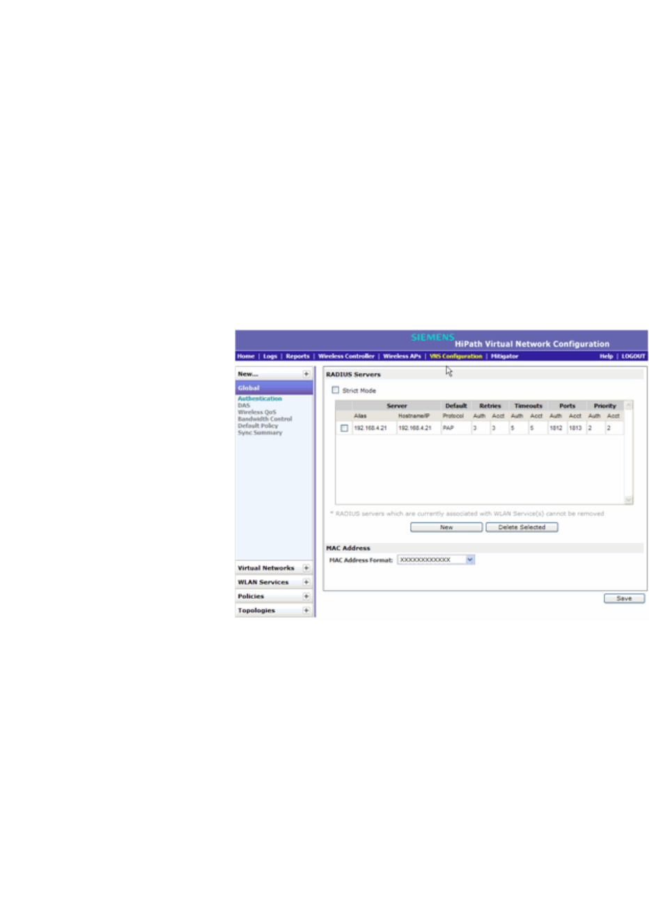
hwc_vnsconfiguration.fm
Configuring a VNS
VNS global settings
9034530-02, March 2010
HiPath Wireless Controller, Access Points and Convergence Software V7.11, User Guide 247
name of the corresponding configuration object, its synchronization mode,
and the status of last synchronization attempt. For more information, see
Section 6.2.7, “Using the Sync Summary”, on page 256.
6.2.1 Defining RADIUS servers and MAC address
format
The Authentication global settings include configuring RADIUS servers and the
MAC format to be used.
To define RADIUS servers for VNS global settings:
1. From the main menu, click Virtual Network Configuration. The Virtual
Network Configuration screen is displayed.
2. In the left pane, click Global, then Authentication.
3. To define a new RADIUS server available on the network, press the New
button. The RADIUS Settings pop up window displays.
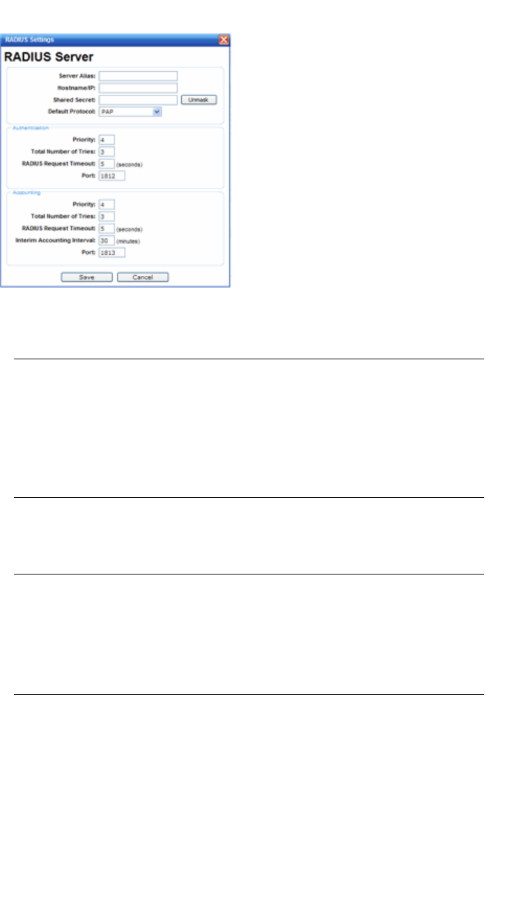
Configuring a VNS
hwc_vnsconfiguration.fm
VNS global settings
9034530-02, March 2010
248 HiPath Wireless Controller, Access Points and Convergence Software V7.11, User Guide
4. In the Server Alias box, type a name that you want to assign to the RADIUS
server.
Note: You can also type the RADIUS server’s IP address in the Server Alias
box in place of a nickname. The RADIUS server will identify itself by the value
typed in the Server Alias box in the RADIUS Servers drop down list on the
RADIUS Authentication tab of the Login Management screen (Main Menu
> Wireless Controller Configuration > Login Management). For more
information, see Section 3.4.9, “Configuring the login authentication mode”,
on page 74.
5. In the Hostname/IP box, type either the RADIUS server’s FQDN (fully
qualified domain name) or IP address.
Note: If you type the host name in the Hostname/IP address box, the HiPath
Wireless Controller will send a host name query to the DNS server for host
name resolution. The DNS servers must be appropriately configured for
resolving the RADIUS servers’ host names. For more information, see
Section 3.4.11, “Configuring DNS servers for resolving host names of
RADIUS servers”, on page 82.
6. In the Shared Secret box, type the password that will be used to validate the
connection between the HiPath Wireless Controller and the RADIUS server.
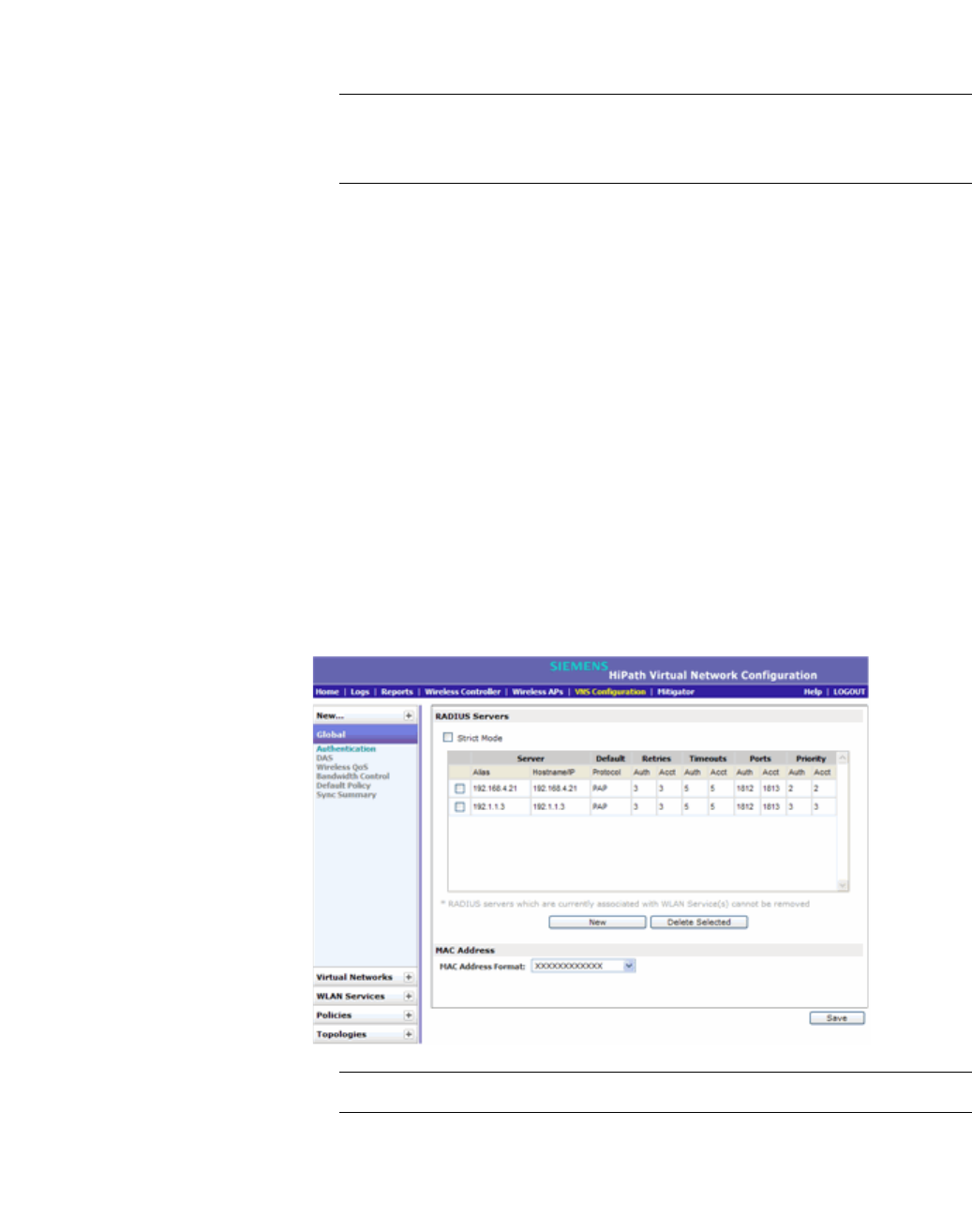
hwc_vnsconfiguration.fm
Configuring a VNS
VNS global settings
9034530-02, March 2010
HiPath Wireless Controller, Access Points and Convergence Software V7.11, User Guide 249
7. To proofread your shared secret key, click Unmask. The password is
displayed.
Note: You should always proofread your Shared Secret key to avoid any
problems later when the HiPath Wireless Controller attempts to communicate
with the RADIUS server.
8. If desired, change the Default Protocol using the drop down list. Choices are
PAP, CHAP, MS-CHAP, or MS-CHAP2.
9. If desired, change the pre-defined default values for Authentication and
Accounting operations:
a) Priority — default is 4
b) Total number of tries — default is 3
c) RADIUS Request timeout — default is 5 seconds
d) Port — default Authentication port is 1812. Default Accounting port is
1813.
e) For Accounting operations, the Interim Accounting Interval — default is
30 minutes.
10. To save your changes, click Save. The new server is displayed in the
RADIUS Servers list.
Note: The RADIUS server is identified by its Server Alias.
11. To edit an existing server, click the row containing the server. The RADIUS
Settings window displays, containing the server’s configuration values.

Configuring a VNS
hwc_vnsconfiguration.fm
VNS global settings
9034530-02, March 2010
250 HiPath Wireless Controller, Access Points and Convergence Software V7.11, User Guide
12. To remove a server from the list, select the checkbox next to the server, and
then click Delete Selected. You can not remove a server that is used by any
VNS.
To configure the global MAC address format:
1. From the main menu, click Virtual Network Configuration. The Virtual
Network Configuration screen is displayed.
2. In the left pane, click Global, then Authentication.
3. In the MAC Address area, select the MAC Address Format from the drop
down list.
4. Click Save to save your changes.
6.2.2 Configuring Dynamic Authorization Server
support
DAS helps secure your network by forcing the disconnection of any mobile device
from your network. Typically, you would want to disconnect any unwelcome or
unauthorized mobile device from your network. The “disconnect message” that is
defined in RFC 3576 is enforced by the DAS support. If an unauthorized mobile
device is detected on the network, the DAS client sends a disconnect packet,
forcing the mobile device off the network. Your DAS client can be an integration
with NAC or another third-party application, including RADIUS applications. For
more information, see Section 5.3, “NAC integration with HiPath WLAN”, on page
230.
DAS support is available to all physical interfaces of the HiPath Wireless
Controller, and by default DAS listens to the standard-specified UDP port 3799.
To configure Dynamic Authorization Server support:
1. From the main menu, click Virtual Network Configuration. The Virtual
Network Configuration screen is displayed.
2. In the left pane, click Global, then click DAS.
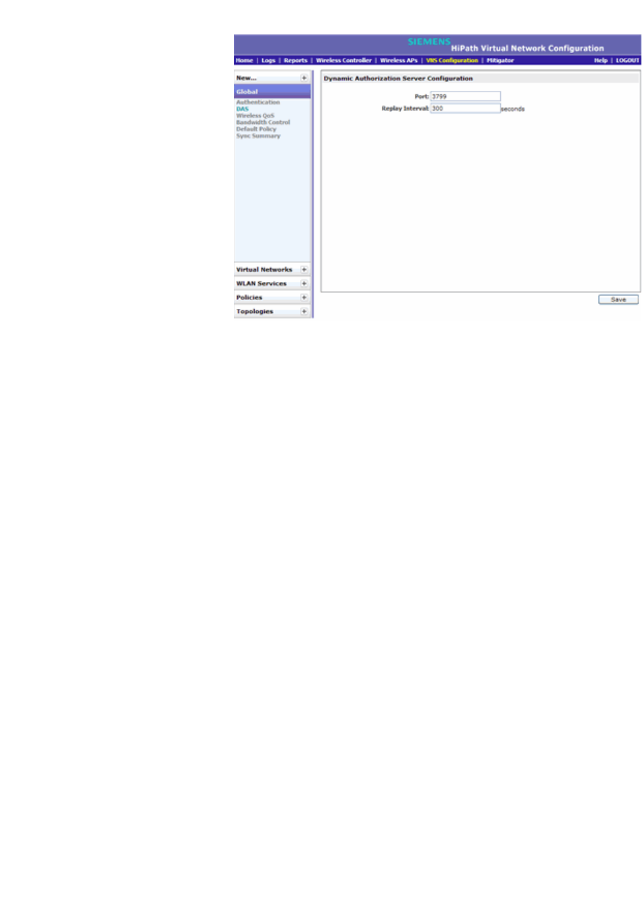
hwc_vnsconfiguration.fm
Configuring a VNS
VNS global settings
9034530-02, March 2010
HiPath Wireless Controller, Access Points and Convergence Software V7.11, User Guide 251
3. In the Port box, type the UDP port you want DAS to monitor. By default, DAS
is configured for the standard-specified UDP port 3799. It is unlikely this port
value needs to be revised.
4. In the Replay Interval box, type how long you want DAS to ignore repeated
identical messages. By default, DAS is configured for 300 seconds.
This time buffer helps defend against replay network attacks.
5. To save your changes, click Save.
6.2.3 Defining Wireless QoS Admission Control
Thresholds
The Wireless QoS global settings include Admisstion Control Thresholds,
described here, and Flexible Client Access, described in Section 6.2.4, “Defining
Wireless QoS Flexible Client Access”, on page 252.
To define admission control thresholds for VNS global settings:
1. From the main menu, click Virtual Network Configuration. The Virtual
Network Configuration screen is displayed.
2. In the left pane, click Global, then click Wireless QoS.
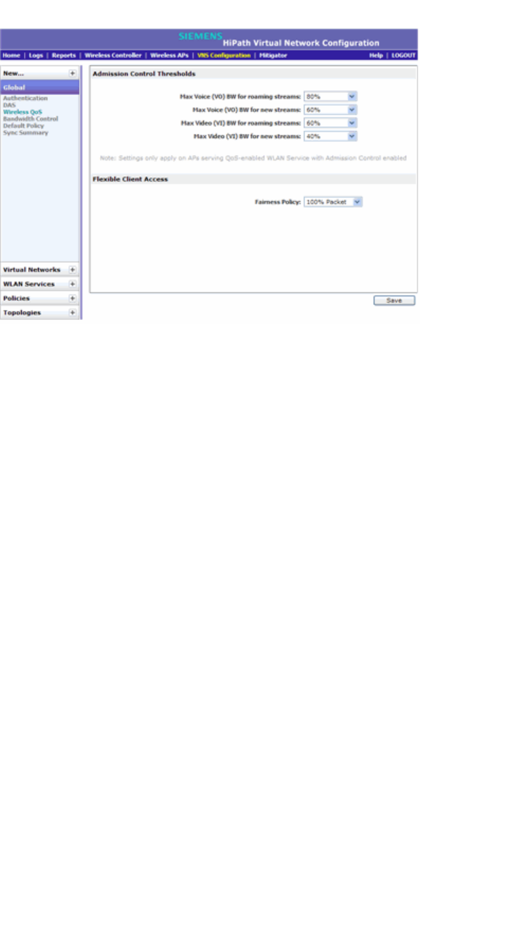
Configuring a VNS
hwc_vnsconfiguration.fm
VNS global settings
9034530-02, March 2010
252 HiPath Wireless Controller, Access Points and Convergence Software V7.11, User Guide
3. In the Admission Control Thresholds area, define the thresholds for the
following:
• Max Voice (VO) BW for roaming streams – The maximum allowed
overall bandwidth on the new AP when a client with an active voice
stream roams to a new AP and requests admission for the voice stream.
• Max Voice (VO) BW for new streams – The maximum allowed overall
bandwidth on an AP when an already associated client requests
admission for a new voice stream.
• Max Video (VI) BW for roaming streams – The maximum allowed
overall bandwidth on the new AP when a client with an active video
stream roams to a new AP and requests admission for the video stream.
• Max Video (VI) BW for new streams – The maximum allowed overall
bandwidth on an AP when an already associated client requests
admission for a new video stream.
These global QoS settings apply to all APs that serve QoS enabled VNSs
with admission control.
4. To save your changes, click Save.
6.2.4 Defining Wireless QoS Flexible Client Access
This feature allows you to adjust client access policy in multiple steps between
“packet fairness” and “airtime fairness.”
•Packet fairness is the default 802.11 access policy. Each WLAN participant
gets the same (equal) opportunity to send packets. All WLAN clients will show
the same throughput, regardless of their PHY rate.
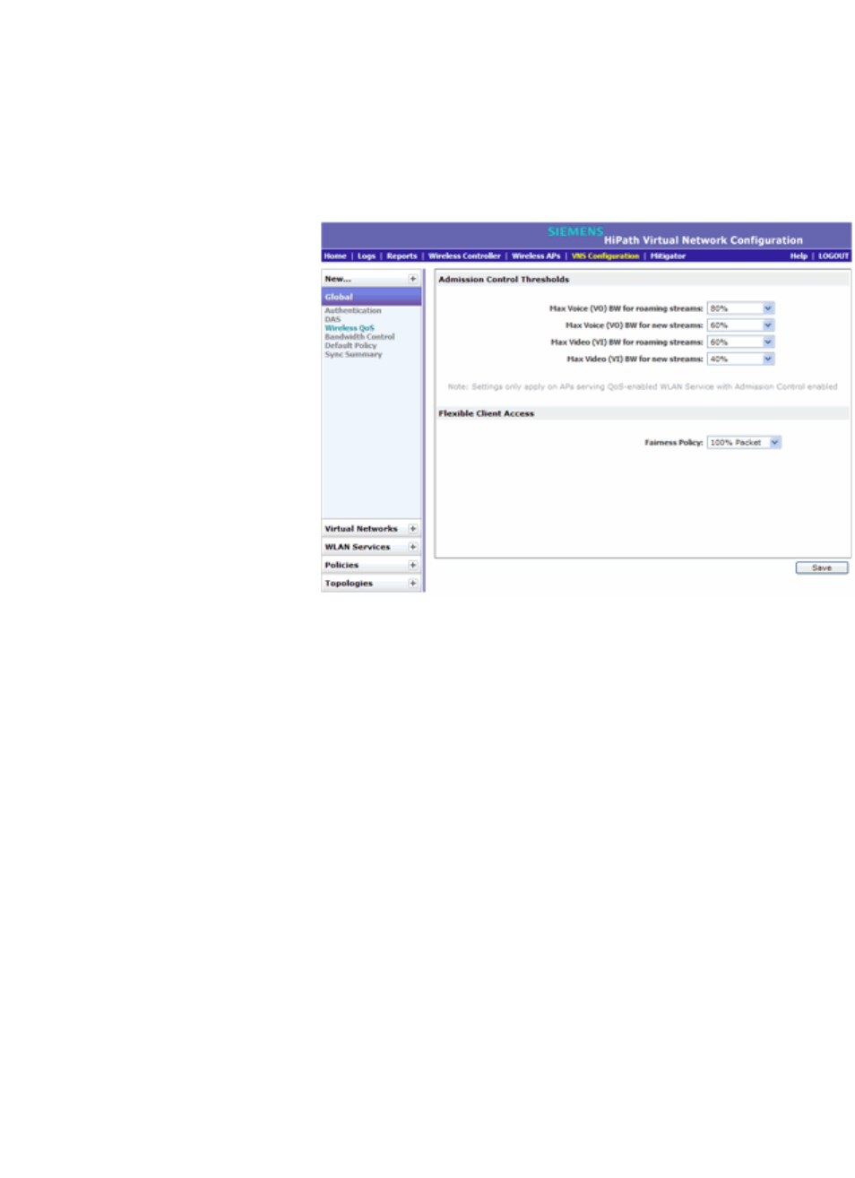
hwc_vnsconfiguration.fm
Configuring a VNS
VNS global settings
9034530-02, March 2010
HiPath Wireless Controller, Access Points and Convergence Software V7.11, User Guide 253
•Airtime fairness gives each WLAN participant the same (equal) time access.
WLAN clients’ throughput will be proportional to their PHY rate.
To define flexible client access for VNS global settings:
1. From the main menu, click Virtual Network Configuration. The Virtual
Network Configuration screen is displayed.
2. In the left pane, click Global, then click Wireless QoS.
3. In the Flexible Client Access area, select a policy from the Fairness Policy
drop-down list. Choices range from 100% packet fairness to 100% airtime
fairness.
4. To save your changes, click Save.
6.2.5 Working with bandwidth control profiles
Bandwidth control limits the amount of bidirectional traffic from a mobile device.
A bandwidth control profile provides a generic definition for the limit applied to certain
wireless clients' traffic. A bandwidth control profile is assigned on a per policy basis.
A bandwidth control profile is not applied to multicast traffic.
Bandwidth control profile parameters
A bandwidth control profile consists of the following parameters:
• Profile Name – Name assigned to a profile
• Committed Information Rate (CIR) – Rate at which the network supports
data transfer under normal operations. It is measured in kilo bytes per second
(Kbps).
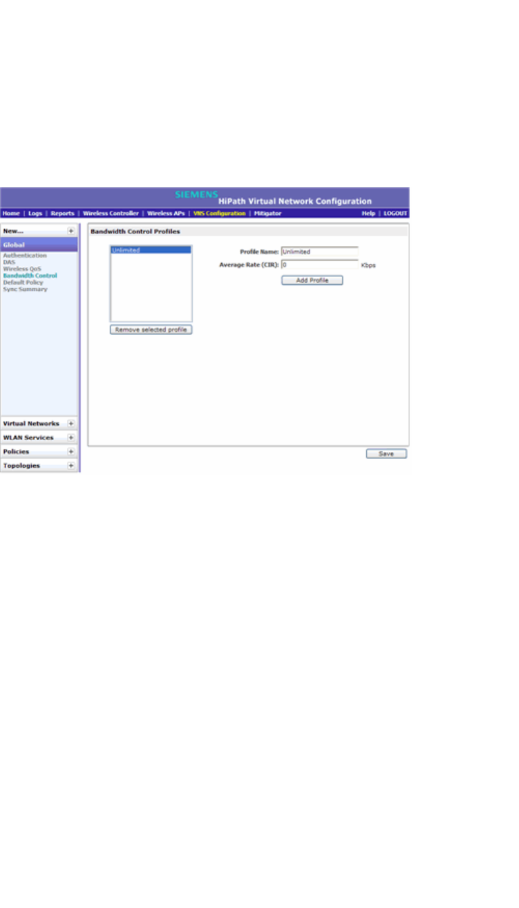
Configuring a VNS
hwc_vnsconfiguration.fm
VNS global settings
9034530-02, March 2010
254 HiPath Wireless Controller, Access Points and Convergence Software V7.11, User Guide
The bandwidth control profiles you define on the VNS Global Settings screen
are displayed as available choices in the Bandwidth Control Profiles list on the
Policy screen.
To create a bandwidth control profile:
1. From the main menu, click Virtual Network Configuration. The Virtual
Network Configuration screen is displayed.
2. In the left pane, click Global, then click Bandwidth Control.
3. Create a bandwidth control profile by doing the following:
• Profile Name – Type a name for the bandwidth control profile.
•In the Average Rate (CIR) – Type the CIR value for the bandwidth control
profile.
4. Click Add Profile. The profile is created and displayed in the Bandwidth
Control Profiles list.
5. Create additional bandwidth control profiles, if applicable.
6. To save your changes, click Save.
6.2.6 Configuring the Global Default Policy
The HiPath Wireless Controller ships with a Global Default Policy that can be
configured. The Global Default Policy specifies:
•A topology to use when a VNS is created using a policy that does not specify
a topology. The default assigned topology is named Bridged at AP untagged.
•An Inbound Rate Profile
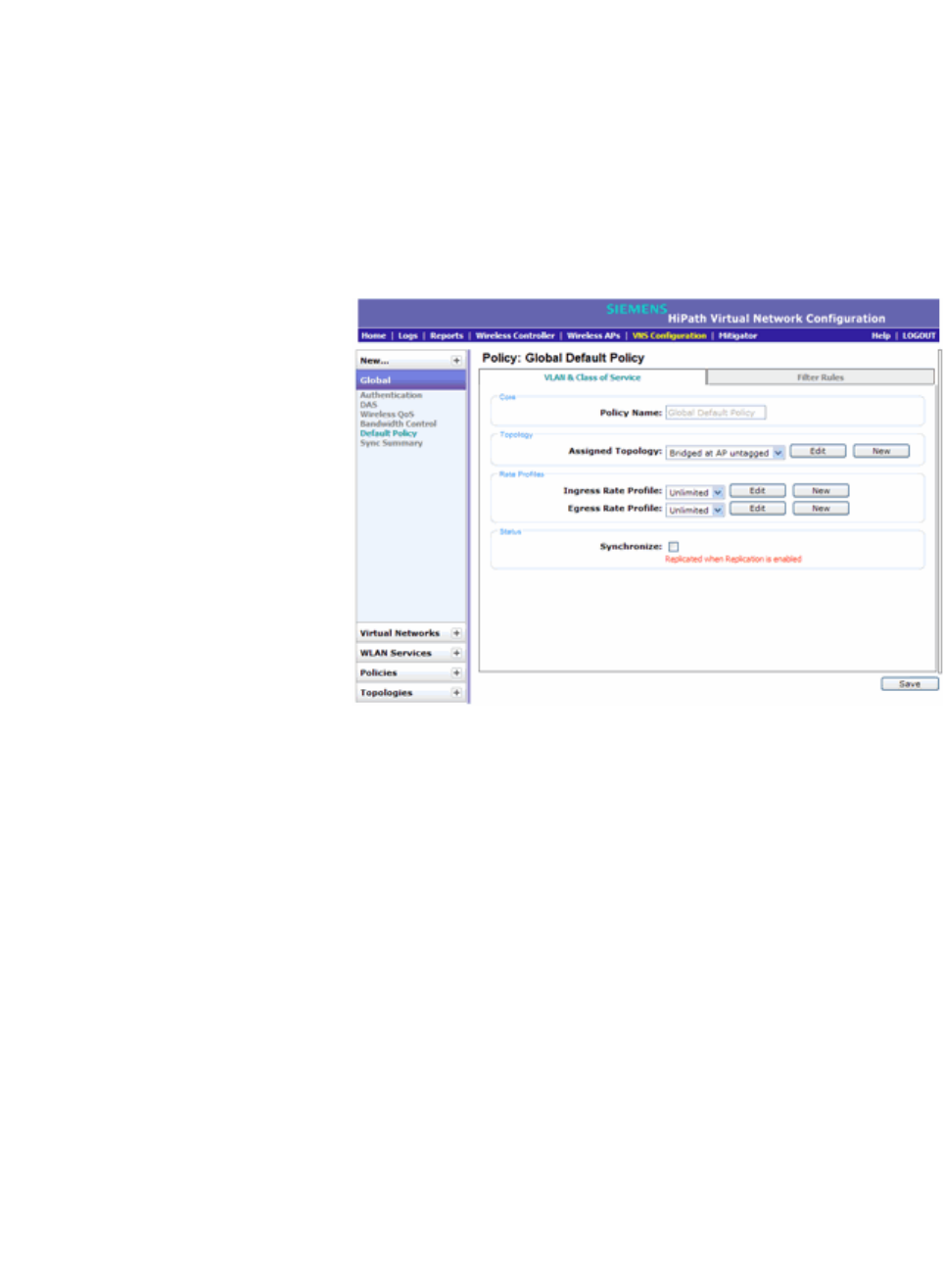
hwc_vnsconfiguration.fm
Configuring a VNS
VNS global settings
9034530-02, March 2010
HiPath Wireless Controller, Access Points and Convergence Software V7.11, User Guide 255
•An Outbound Rate Profile
•A set of filters
To configure the topology and rate profiles:
1. From the main menu, click Virtual Network Configuration. The Virtual
Network Configuration screen is displayed.
2. In the left pane, click Global, then click Default Policy.
3. Select the VLAN & Class of Service tab.
4. In the Toplogy area, select a topology using one of the following methods:
•Select an existing topology from the Assigned Topology drop-down list.
•Select an existing topology from the Assigned Topology drop-down list,
then click Edit. The Edit Topology window displays, showing the current
values for the selected topology.
•Click the New button. The New Topology window displays.
Edit or create the selected topology as described in Section 6.8, “Configuring
a Topology”, on page 296.
5. In the Rate Profiles area, select ingress and egress rate profiles using one
of the following methods:
•Select an existing Ingress Rate Profile and Egress Rate Profile from
the drop-down lists.
•Select an existing rate from the drop-down lists, then click Edit. The Edit
Rate Control Profile window displays.
•Click the New button. The Add Rate Control Profile window displays.
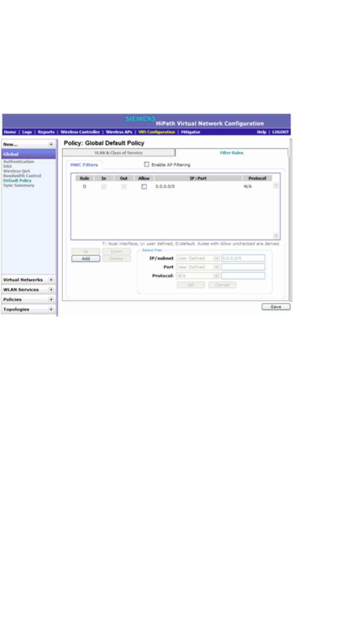
Configuring a VNS
hwc_vnsconfiguration.fm
VNS global settings
9034530-02, March 2010
256 HiPath Wireless Controller, Access Points and Convergence Software V7.11, User Guide
Edit or create the rate control profile as described in Section 6.10,
“Configuring Policy”, on page 350.
To configure the filters:
1. Click the Filter Rules tab. The HWC Filters tab displays, allowing you to
create filter rules that will be applied by the controller when default non-
authentication policy does not specify filters.
2. To add a rule, click Add. The fields in the Add Filter area are enabled.
3. Configure the fields as desired. For more information, see Section 6.10.2,
“About filtering rules”, on page 352.
4. To configure custom AP filters, select the Enable AP Filtering checkbox,
then select the Custom AP Filters checkbox and click the AP Filters tab.
Then configure the rules as desired.
For more information, see Section 6.10.6, “Defining filter rules for Wireless
APs”, on page 360.
6.2.7 Using the Sync Summary
The Sync Summary screen provides an overview of the synchronization status of
paired controllers. The screen is divided into 4 sections: Virtual Networks, WLAN
services, Policies and Topologies. Each section lists the name of the
corresponding configuration object, its synchronization mode, and the status of
last synchronization attempt.
If Synchronization of an object is not enabled, then there is a button in the Status
field which says "Synchronize Now", which performs a single synchronization of
the object, pushing the object from local controller to the peer.
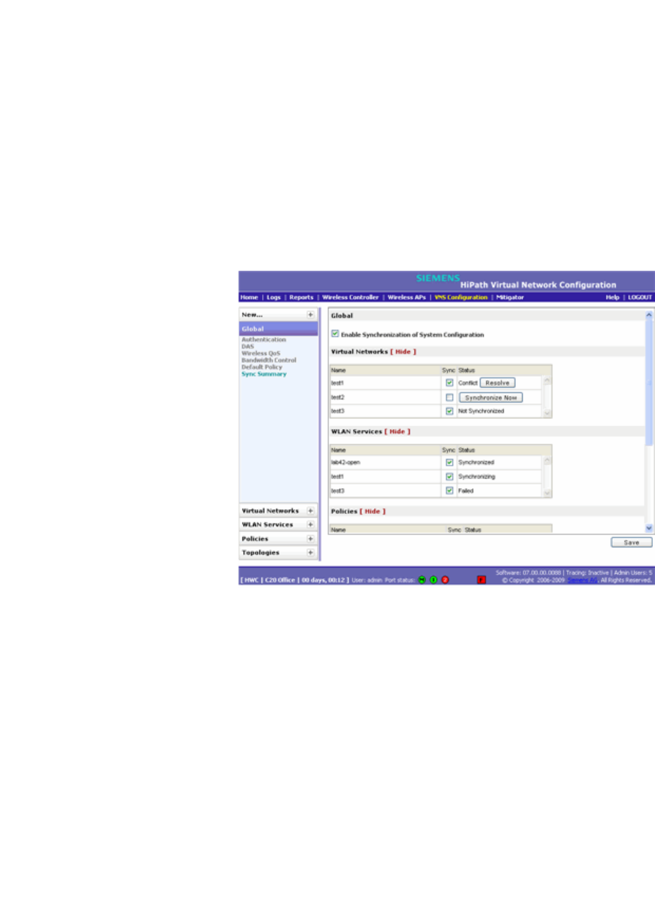
hwc_vnsconfiguration.fm
Configuring a VNS
VNS global settings
9034530-02, March 2010
HiPath Wireless Controller, Access Points and Convergence Software V7.11, User Guide 257
If Synchronization of an object is enabled, then the "Status" field can have the
following values:
•Synchronized
•Not Synchronized
•Failed
•Conflict (with a button called "Resolve")
The checkbox "Enable Synchronization of System Configuration" acts as a global
synchronization flag. When it's disabled, synchronization is not performed in the
background. When it is enabled, only the objects that have "Sync" enabled are
synchronized.
An object may have a synchronization state of "Conflict" if it was updated on both
controllers in the availability pair while the availability link was down. In such a
case, the "Resolve" button lets you choose which version of the object should be
taken, local or remote. Please note that controllers don't compare the actual
configuration when they declare a conflict — only the fact that the object was
updated on both controllers in the availability pair triggers the "Conflict" state.
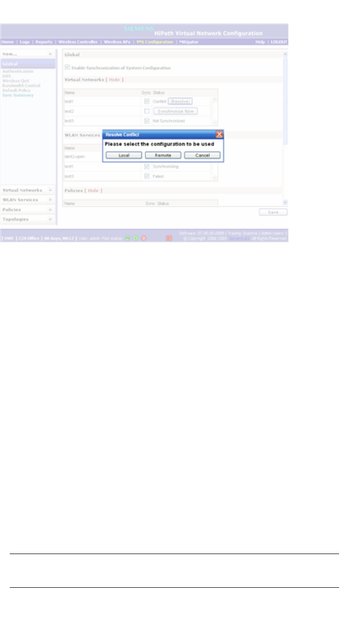
Configuring a VNS
hwc_vnsconfiguration.fm
Methods for configuring a VNS
9034530-02, March 2010
258 HiPath Wireless Controller, Access Points and Convergence Software V7.11, User Guide
6.3 Methods for configuring a VNS
To configure a VNS, you can use one of the following methods:
• Wizard configuration – The VNS wizard helps create and configure a new
VNS by prompting administrators for a minimum amount of configuration
information. The VNS is created using minimum parameters. The remaining
parameters are automatically assigned in accordance with best practice
standards.
After the VNS wizard completes the VNS creation process, you can then edit
or revise any of the VNS configuration to suit your network needs.
• Advanced configuration – Advanced configuration allows administrators to
create a new VNS by first configuring the topology, policy, and WLAN services
and then configuring any remaining individual VNS tabs that are necessary to
complete the process.
When configuring a VNS, you can navigate between the various VNS tabs
and define your configuration without having to save your changes on each
individual tab. After your VNS configuration is complete, click Save on any
VNS tab to save your completed VNS configuration.
Note: If you navigate away from the VNS configuration tabs without saving
your VNS changes, your VNS configuration changes will be lost.

hwc_vnsconfiguration.fm
Configuring a VNS
Working with the VNS wizard to create a new VNS
9034530-02, March 2010
HiPath Wireless Controller, Access Points and Convergence Software V7.11, User Guide 259
6.4 Working with the VNS wizard to create a new VNS
The VNS wizard helps create and configure a new VNS by prompting
administrators for a minimum amount of configuration information during the
sequential configuration process. After the VNS wizard completes the VNS
creation process, you can then continue to configure or revise any of the VNS
configuration to suit your network needs.
When using the VNS wizard to create a new VNS, you can create the following
types of VNSs:
• NAC SSID-based VNS – This is a NAC gateway-compatible VNS. The
HiPath Wireless Controller integrates with an Enterasys NAC Controller to
provide authentication, assessment, remediation and access control for
mobile users. For more information, see Section 6.4.1, “Creating a NAC VNS
using the VNS wizard”, on page 259.
•Voice – This is a voice-specific VNS that can support various wireless
telephones, including optiPoint, Spectralink, Vocera, and Mobile Connect -
Nokia. For more information, see Section 6.4.2, “Creating a voice VNS using
the VNS wizard”, on page 262.
•Data – This is a data-specific VNS, that can be configured to use either SSID
or AAA authentication. For more information, see Section 6.4.3, “Creating a
data VNS using the VNS wizard”, on page 267.
• Captive Portal – This is a VNS that employs a Captive Portal page, which
requires mobile users to provide login credentials when prompted to access
network services. In addition, use the VNS wizard to configure a GuestPortal
VNS using the Captive Portal option. For more information, see Section 6.4.4,
“Creating a Captive Portal VNS using the VNS wizard”, on page 273.
•Other – Use this VNS wizard option to create a VNS as you would if you were
creating a new VNS using the advanced configuration method. For more
information, see Section 6.6, “Creating a VNS using the advanced method”,
on page 293.
The VNS type dictates the configuration information that is required during the
VNS creation process.
6.4.1 Creating a NAC VNS using the VNS wizard
The HiPath Wireless Controller integrates with an Enterasys NAC Controller to
provide authentication, assessment, remediation and access control for mobile
users. For more information, see Section 5.3, “NAC integration with HiPath
WLAN”, on page 230.
Use the VNS wizard to configure a NAC gateway-compatible VNS by defining the
following essential parameters:
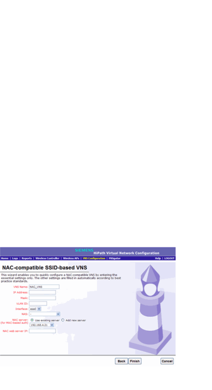
Configuring a VNS
hwc_vnsconfiguration.fm
Working with the VNS wizard to create a new VNS
9034530-02, March 2010
260 HiPath Wireless Controller, Access Points and Convergence Software V7.11, User Guide
•VNS Name – The name that will be assigned to the VNS and SSID.
•IP Address – The IP address of the HiPath Wireless Controller’s interface on
the VLAN.
• Mask – The subnet mask for the IP address to separate the network portion
from the host portion of the address.
• VLAN ID – ID number of the VLAN to which the HiPath Wireless Controller is
bridged for the VNS.
•Port – Physical L2 port to which the configured VLAN is attached.
• RADIUS server – IP address of the Enterasys NAC Controller.
• Redirection URL – The URL that points to the NAC Controller’s web server.
The VNS wizard creates a Bridge Traffic Locally at HWC VNS. This VNS has
the crucial attributes — SSID Network Assignment Type, MAC-based external
captive portal authentication and WPA-PSK encryption — that makes it
compatible with the Enterasys NAC Controller.The remaining VNS parameters
are defined automatically according to best practice standards.
To configure a NAC VNS using the VNS wizard:
1. From the main menu, click Virtual Network Configuration. The Virtual
Network Configuration screen is displayed.
2. In the left pane, expand the New pane, then click START VNS WIZARD. The
VNS Creation Wizard screen is displayed.
3. In the Name box, type a name for the NAC SSID-based VNS.
4. In the Category drop-down list, click NAC VNS, and then click Next. The
NAC-compatible SSID-based VNS screen is displayed.

hwc_vnsconfiguration.fm
Configuring a VNS
Working with the VNS wizard to create a new VNS
9034530-02, March 2010
HiPath Wireless Controller, Access Points and Convergence Software V7.11, User Guide 261
5. Do the following:
•In the IP address box, type the IP address of the HiPath Wireless
Controller’s interface on the VLAN.
•In the Mask box, type the appropriate subnet mask for this IP address to
separate the network portion from the host portion of the address
(typically 255.255.255.0).
•In the VLAN ID box, type the VLAN tag to which the HiPath Wireless
Controller will be bridged for the VNS.
•In the Interface drop-down list, select the physical port that provides the
access to the VLAN.
•In the NAS drop-down list, click the interface/port through which the NAC
gateway will communicate with the HiPath Wireless Controller. The IP
address in this field will be used as the NAS IP RADIUS attribute when
communicating with the NAC gateway.
•In the NAC server drop-down list, click the existing NAC server you want
to use for the VNS, or select the Add new server option, and then do the
following:
a) In the Server Alias box, type the name or IP address of the NAC
server.
b) In the Hostname/IP box, type the NAC server’s FQDN (fully qualified
domain name) or IP address.
c) In the Shared Secret box, type the password that will be used to
validate the connection between the HiPath Wireless Controller and
the NAC server.
d) To proofread your shared secret key, click Unmask. The password is
displayed.
After the new NAC server is added, it will be displayed in the Use existing
server drop-down list the next time you use the VNS wizard.
Note: You should always proofread your Shared Secret key to avoid any
problems later when the HiPath Wireless Controller attempts to communicate
with the NAC Controller.
e) In the NAC web server IP box, type the NAC web server IP address.
6. To save your changes, click Finish. The VNS wizard creates a SSID-based
NAC Controller-compatible VNS, and displays the configuration summary.
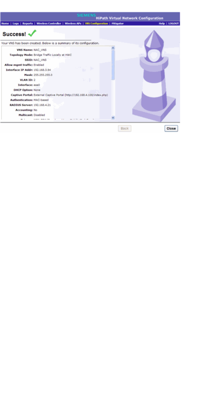
Configuring a VNS
hwc_vnsconfiguration.fm
Working with the VNS wizard to create a new VNS
9034530-02, March 2010
262 HiPath Wireless Controller, Access Points and Convergence Software V7.11, User Guide
7. To close the VNS wizard, click Close.
8. If applicable, you can continue to configure or edit the new VNS by clicking
the individual VNS configuration tabs.
6.4.2 Creating a voice VNS using the VNS wizard
Use the VNS wizard to create a voice-specific VNS that can support various
wireless telephones, including optiPoint, Spectralink, Vocera, and Mobile
Connect - Nokia.
When you use the VNS wizard to create a voice-specific VNS, you optimize the
voice VNS to support one wireless telephone vendor. If the voice VNS needs to
be optimized for more than one wireless phone vendor, use the advanced method
to create the voice-specific VNS. For more information, see Section 6.6, “Creating
a VNS using the advanced method”, on page 293.
When you create a new voice VNS using the VNS wizard, you configure the VNS
in the following stages:
•Basic settings
•Authentication settings, if applicable
•DHCP settings
•Privacy settings
•Radio assignment settings
•Summary

hwc_vnsconfiguration.fm
Configuring a VNS
Working with the VNS wizard to create a new VNS
9034530-02, March 2010
HiPath Wireless Controller, Access Points and Convergence Software V7.11, User Guide 263
To configure a voice VNS using the VNS wizard:
1. From the main menu, click Virtual Network Configuration. The Virtual
Network Configuration screen is displayed.
2. In the left pane, expand the New pane, then click START VNS WIZARD. The
VNS Creation Wizard screen is displayed.
3. Click Start VNS Wizard. The VNS Creation Wizard screen is displayed.
4. In the Name box, type a name for the voice VNS.
5. In the Category drop-down list, click Voice, and then click Next. The Basic
Settings screen is displayed.
6. Configure the VNS basic settings. The VNS type and mode you configure on
the Basic Settings screen will dictate the VNS information you will need to
provide.
• Enabled – By default, the Enabled checkbox for the new VNS is enabled.
A VNS must be enabled for it to be able to provide service for mobile user
traffic.
•Type – Click the wireless phone you want to support for the new voice
VNS you are creating.
• Mode – Click the VNS mode you want to assign:
• Routed is a VNS type where user traffic is tunneled to the HiPath
Wireless Controller.
• Bridge Traffic Locally at HWC is a VNS type that has associated
with it a Topology with a mode of Bridge Traffic Locally at HWC. User
traffic is tunneled to the HiPath Wireless Controller and is directly
bridged at the controller to a specific VLAN. With this VNS type,
mobile users become a natural extension of a VLAN subnet. For each
Bridge Traffic Locally at HWC VNS that is created, a VLAN needs to
be specified. In addition, the network port on which the VLAN is
assigned must be configured on the switch, and the corresponding
HiPath Wireless Controller interface must match the correct VLAN.
If you configure a routed voice VNS
Do the following:
a) Gateway – Type the HiPath Wireless Controller's own IP address of the
topology associated with that VNS. This IP address is also the default
gateway for the VNS. The HiPath Wireless Controller advertises this
address to the wireless devices when they sign on. For routed VNSs, it
corresponds to the IP address that is communicated to mobile users (in

Configuring a VNS
hwc_vnsconfiguration.fm
Working with the VNS wizard to create a new VNS
9034530-02, March 2010
264 HiPath Wireless Controller, Access Points and Convergence Software V7.11, User Guide
the VNS) as the default gateway for the VNS subnet. (Mobile users target
the HiPath Wireless Controller's interface in their effort to route packets to
an external host).
b) Mask – Type the appropriate subnet mask for this IP address to separate
the network portion from the host portion of the address (typically
255.255.255.0).
c) Gateway/SVP – If the voice VNS is to support Spectralink wireless
phones, type the IP address of the SpectraLink Voice Protocol (SVP)
gateway.
d) Vocera Server – If the voice VNS is to support Vocera wireless phones,
type the IP address of the Vocera server.
e) PBX – If the voice VNS is to support either WL2 or Mobile Connect -
Nokia wireless phones, type the PBX IP address.
f) Enable Authentication – If applicable, select this checkbox to enable
authentication for the new voice VNS.
g) Enable DHCP – By default, this option is selected.
If you configure a bridge traffic locally at the HWC voice VNS
Do the following:
a) Interface – Click the physical interface that provides the access to the
VLAN.
b) Interface IP address – Type the IP address of the HiPath Wireless
Controller’s interface on the VLAN.
c) Mask – Type the appropriate subnet mask for this IP address to separate
the network portion from the host portion of the address (typically
255.255.255.0).
d) VLAN ID – Type the VLAN tag to which the HiPath Wireless Controller
will be bridged for the VNS.
e) Gateway/SVP – If the voice VNS is to support Spectralink wireless
phones, type the IP address of the SpectraLink Voice Protocol (SVP)
gateway.
f) Vocera Server – If the voice VNS is to support Vocera wireless phones,
type the IP address of the Vocera server.
g) PBX Server – If the voice VNS is to support either WL2 or Mobile
Connect - Nokia wireless phones, type the PBX IP address.
h) Enable Authentication – If applicable, select this checkbox to enable
authentication for the new voice VNS.

hwc_vnsconfiguration.fm
Configuring a VNS
Working with the VNS wizard to create a new VNS
9034530-02, March 2010
HiPath Wireless Controller, Access Points and Convergence Software V7.11, User Guide 265
i) Enable DHCP – If applicable, select this checkbox to enable DHCP
authentication for the new voice VNS.
7. Click Next.
If the Enable Authentication checkbox is selected, you now must configure
the Authentication properties of the new voice VNS. Continue with step 8.
If the Enable Authentication checkbox is clear, you must now configure the
DHCP properties of the new voice VNS. Continue with step 10.
8. On the Authentication screen, do the following:
• Radius Server – Click the RADIUS server you want to assign to the new
voice VNS, or click Add New Server and then do the following:
•Server Alias – Type a name you want to assign to the new RADIUS
server.
•Hostname/IP – Type either the RADIUS server’s FQDN (fully
qualified domain name) or IP address.
• Shared Secret – Type the password that will be used to validate the
connection between the HiPath Wireless Controller and the RADIUS
server.
• Mask/Unmask – Click to display or hide your shared secret key.
•Roles – Select the authentication role options for the RADIUS server.
MAC-based Authentication – Select to enable the RADIUS server to
perform MAC-based authentication on the voice VNS.
If applicable, and the MAC-based authentication option is enabled,
select to enable MAC-based authorization on roam.
9. Click Next. The DHCP screen is displayed.
10. On the DHCP screen, in the DHCP Option drop-down list, click one of the
following:
• Use DHCP Relay – Using DHCP relay forces the HiPath Wireless
Controller to forward DHCP requests to an external DHCP server on the
enterprise network. DHCP relay bypasses the local DHCP server for the
HiPath Wireless Controller and allows the enterprise to manage IP
address allocation to a VNS from its existing infrastructure.
–DHCP Servers – Type the IP address of the DHCP server to which
DHCP discover and request messages will be forwarded for clients on
this VNS. The HiPath Wireless Controller does not handle DHCP
requests from users, but instead forwards the requests to the
indicated DHCP server.
The DHCP server must be configured to match the VNS settings. In
particular for a Routed VNS, the DHCP server must identify the

Configuring a VNS
hwc_vnsconfiguration.fm
Working with the VNS wizard to create a new VNS
9034530-02, March 2010
266 HiPath Wireless Controller, Access Points and Convergence Software V7.11, User Guide
HiPath Wireless Controller's interface IP as the default Gateway
(router) for the subnet. (Users intending to reach devices outside of
the subnet will forward the packets to the default gateway (controller)
for delivery upstream.)
• Local DHCP Server – If applicable, edit the local DHCP server settings.
11. In the DNS Servers box, type the IP Address of the Domain Name Servers
to be used.
12. In the WINS box, type the IP address if the DHCP server uses Windows
Internet Naming Service (WINS).
13. Click Next. The Privacy screen is displayed. Most options on this screen are
view-only.
14. On the Privacy screen, do the following:
• Pre-shared key – Type the shared secret key to be used between the
wireless device and Wireless AP. The shared secret key is used to
generate the 256-bit key.
• Mask/Unmask – Click to display or hide your shared secret key.
15. Click Next. The Radio Assignment screen is displayed.
16. On the Radio Assignment screen, do the following:
•In the AP Default Settings section, select the radios of the AP default
settings profile that you want to broadcast the voice VNS.
•In the AP Selection section, select the group of APs that will broadcast
the voice VNS:
• all radios – Click to assign all of the APs’ radios.
• radio 1 – Click to assign only the APs’ Radio 1.
• radio 2– Click to assign only the APs’ Radio 2.
• local APs - all radios – Click to assign only the local APs.
• local APs - radio 1 – Click to assign only the local APs’ Radio 1.
• local APs - radio 2 – Click to assign only the local APs’ Radio 2.
• foreign APs - all radios – Click to assign only the foreign APs.
• foreign APs - radio 1 – Click to assign only the foreign APs’ Radio 1.
• foreign APs - radio 2 – Click to assign only the foreign APs’ Radio 2.
•If applicable, select the WMM checkbox. WMM (Wi-Fi Multimedia), if
enabled on an individual VNS, provides multimedia enhancements that
improve the user experience for audio, video, and voice applications.
WMM is part of the 802.11e standard for QoS. If enabled, the AP will

hwc_vnsconfiguration.fm
Configuring a VNS
Working with the VNS wizard to create a new VNS
9034530-02, March 2010
HiPath Wireless Controller, Access Points and Convergence Software V7.11, User Guide 267
accept WMM client associations, and will classify and prioritize the
downlink traffic for all WMM clients. WMM clients will also classify and
prioritize the uplink traffic.
17. Click Next. The Summary screen is displayed.
18. Confirm your voice VNS configuration. To revise your configuration, click
Back.
19. To create your VNS, click Finish, and then click Close.
20. If applicable, you can continue to configure or edit the new VNS by clicking
the individual VNS configuration tabs.
6.4.3 Creating a data VNS using the VNS wizard
Use the VNS wizard to create a data-specific VNS that can be configured to use
either SSID or AAA authentication.
When you create a new data VNS using the VNS wizard, you configure the VNS
in the following stages:
•Basic settings
•Authentication settings
•DHCP settings
•Filter settings
•Privacy settings
•Radio assignment settings
•Summary
To configure a data VNS using the VNS wizard:
1. From the main menu, click Virtual Network Configuration. The Virtual
Network Configuration screen is displayed.
2. In the left pane, expand the New pane, then click START VNS WIZARD. The
VNS Creation Wizard screen is displayed.
3. Click Start VNS Wizard. The VNS Creation Wizard screen is displayed.
4. In the Name box, type a name for the data VNS.
5. In the Category drop-down list, click Data, and then click Next. The Basic
Settings screen is displayed.
6. Configure the data VNS basic settings. The VNS type and mode you
configure on the Basic Settings screen will dictate the VNS information you
will need to provide.

Configuring a VNS
hwc_vnsconfiguration.fm
Working with the VNS wizard to create a new VNS
9034530-02, March 2010
268 HiPath Wireless Controller, Access Points and Convergence Software V7.11, User Guide
•Enabled – By default, the Enabled checkbox for the new VNS is enabled.
A VNS must be enabled for it to be able to provide service for mobile user
traffic.
•Type – Click the type of network assignment for the VNS. There are two
options for network assignment, Disabled or 802.1x..
•Mode – Click the VNS mode you want to assign:
•Routed is a VNS type where user traffic is tunneled to the HiPath
Wireless Controller.
• Bridge Traffic Locally at HWC is a VNS type where user traffic is
tunneled to the HiPath Wireless Controller and is directly bridged at
the controller to a specific VLAN. With this VNS type, mobile users
become a natural extension of a VLAN subnet. For each Bridge
Traffic Locally at HWC VNS that is created, a VLAN needs to be
specified. In addition, the network port on which the VLAN is assigned
must be configured on the switch, and the corresponding HiPath
Wireless Controller interface must match the correct VLAN.
• Bridge Traffic Locally at AP is a VNS type where user traffic is
directly bridged to a VLAN at the AP network point of access (switch
port).
If you are configuring a routed data VNS
Do the following:
a) Gateway – Type the HiPath Wireless Controller's own IP address of the
topology associated with that VNS. This IP address is the default gateway
for the VNS. The HiPath Wireless Controller advertises this address to
the wireless devices when they sign on. For routed VNSs, it corresponds
to the IP address that is communicated to mobile users (in the VNS) as
the default gateway for the VNS subnet. (Mobile users target the HiPath
Wireless Controller's interface in their effort to route packets to an
external host).
b) Mask – Type the appropriate subnet mask for this IP address to separate
the network portion from the host portion of the address (typically
255.255.255.0).
c) Enable Authentication – This option is enabled by default if the Type is
802.1x.
d) Enable DHCP – By default, this option is enabled for a routed data VNS.
If you configuring a bridge traffic locally at AP data VNS
Do the following:

hwc_vnsconfiguration.fm
Configuring a VNS
Working with the VNS wizard to create a new VNS
9034530-02, March 2010
HiPath Wireless Controller, Access Points and Convergence Software V7.11, User Guide 269
a) Tagged – Select if you want to assign this VNS to a specific VLAN.
b) VLAN ID – Type the VLAN tag to which the HiPath Wireless Controller
will be bridged for the data VNS.
c) Untagged – Select if you want this VNS to be untagged. This option is
selected by default.
d) Enable Authentication – If applicable, select this checkbox to enable
authentication for the new data VNS. This option is enabled by default if
the Type is 802.1x.
If you are configuring a bridge traffic locally at HWC data VNS
Do the following:
a) Interface – Click the physical port that provides the access to the VLAN.
b) Interface IP address – Type the IP address of the HiPath Wireless
Controller’s interface on the VLAN.
c) Mask – Type the appropriate subnet mask for this IP address to separate
the network portion from the host portion of the address (typically
255.255.255.0).
d) VLAN ID – Type the VLAN tag to which the HiPath Wireless Controller
will be bridged for the VNS.
e) Enable Authentication – If applicable, select this checkbox to enable
authentication for the new data VNS. This option is enabled by default if
the Type is 802.1x.
f) Enable DHCP – If applicable, select this checkbox to enable DHCP
authentication for the new data VNS.
7. Click Next. The Authentication screen is displayed.
8. On the Authentication screen, do the following:
• Radius Server – Click the RADIUS server you want to assign to the new
data VNS, or click Add New Server and then do the following:
•Server Alias – Type a name you want to assign to the new RADIUS
server.
•Hostname/IP – Type either the RADIUS server’s FQDN (fully
qualified domain name) or IP address.
• Shared Secret – Type the password that will be used to validate the
connection between the HiPath Wireless Controller and the RADIUS
server.
• Mask/Unmask – Click to display or hide your shared secret key.
•Roles – Select the authentication role options for the RADIUS server:

Configuring a VNS
hwc_vnsconfiguration.fm
Working with the VNS wizard to create a new VNS
9034530-02, March 2010
270 HiPath Wireless Controller, Access Points and Convergence Software V7.11, User Guide
• MAC-based Authentication – Select to enable the RADIUS server
to perform MAC-based authentication on the data VNS.
If applicable, and the MAC-based authentication option is enabled,
select to enable MAC-based authorization on roam.
9. Click Next. The DHCP screen is displayed, if DHCP was enabled previously.
10. In the DHCP Option drop-down list, click one of the following:
• Use DHCP Relay – Using DHCP relay forces the HiPath Wireless
Controller to forward DHCP requests to an external DHCP server on the
enterprise network. DHCP relay bypasses the local DHCP server for the
HiPath Wireless Controller and allows the enterprise to manage IP
address allocation to a VNS from its existing infrastructure.
–DHCP Servers – If Use DHCP Relay was selected, type the IP
address of the DHCP server to which DHCP discover and request
messages will be forwarded for clients on this VNS. The HiPath
Wireless Controller does not handle DHCP requests from users, but
instead forwards the requests to the indicated DHCP server.
The DHCP server must be configured to match the VNS settings. In
particular for a Routed VNS, the DHCP server must identify the
HiPath Wireless Controller's interface IP as the default Gateway
(router) for the subnet. (Users intending to reach devices outside of
the subnet will forward the packets to the default gateway (controller)
for delivery upstream.)
• Local DHCP Server – If applicable, edit the local DHCP server settings.
11. In the DNS Servers box, type the IP Address of the Domain Name Servers
to be used.
12. In the WINS box, type the IP address if the DHCP server uses Windows
Internet Naming Service (WINS).
13. Click Next. The Filtering screen is displayed.
14. On the Filtering screen, do the following:
•In the Filter ID drop-down list, click one of the following:
•Default – Controls access if there is no matching filter ID for a user.
• Exception – Protects access to the HiPath Wireless Controller’s own
interfaces, including the VNSs own interface. VNS exception filters
are applied to user traffic intended for the HiPath Wireless Controller's
own interface point on the VNS. These filters are applied after the
user's specific VNS state assigned filters.
15. In the Filter table, select the Allow or Deny option buttons for each filter if
applicable, and then select the Enable checkbox accordingly.

hwc_vnsconfiguration.fm
Configuring a VNS
Working with the VNS wizard to create a new VNS
9034530-02, March 2010
HiPath Wireless Controller, Access Points and Convergence Software V7.11, User Guide 271
16. Click Next. The Privacy screen is displayed.
17. On the Privacy screen, select one of the following:
• Static Keys – Select to configure static keys. Then enter:
–WEP Key Length – Click the WEP encryption key length: 64 bit, 128
bit, or 152 bit.
– Select an Input Method:
Input Hex – type the WEP key input in the WEP Key box. The key is
generated automatically based on the input.
Input String – type the secret WEP key string used for encrypting
and decrypting in the WEP Key String box. The WEP Key box is
automatically filled by the corresponding Hex code.
•WPA-PSK – Select to configure Wi-Fi Protected Access (WPA v1 and
WPA v2), a security solution that adds authentication to enhanced WEP
encryption and key management.
– To enable WPA v1 encryption, select WPA v.1. In the Encryption
drop-down list, select one of the following encryption types:
Auto – The Wireless AP will advertise both TKIP and CCMP (Counter
Mode with Cipher Block Chaining Message Authentication Code
Protocol) for WPAv1. CCMP is an IEEE 802.11i encryption protocol
that uses the encryption cipher AES (Advanced Encryption
Standard).
TKIP only – The AP will advertise TKIP as an available encryption
protocol for WPAv1. It will not advertise CCMP.
– To enable WPA v2 encryption, select WPA v.2. In the Encryption
drop-down list, click one of the following encryption types:
Auto – The AP advertises both TKIP and CCMP (counter mode with
cipher block chaining message authentication code protocol). CCMP
is an IEEE 802.11i encryption protocol that uses the encryption cipher
AES (Advanced Encryption Standard).
AES only – The AP advertises CCMP as an available encryption
protocol. It will not advertise TKIP.
– To enable re-keying after a time interval, select Broadcast re-key
interval, then type the time interval after which the broadcast
encryption key is changed automatically. The default is 3600.
If this checkbox is not selected, the Broadcast encryption key is never
changed and the Wireless AP will always use the same broadcast key
for Broadcast/Multicast transmissions. This will reduce the level of
security for wireless communications.

Configuring a VNS
hwc_vnsconfiguration.fm
Working with the VNS wizard to create a new VNS
9034530-02, March 2010
272 HiPath Wireless Controller, Access Points and Convergence Software V7.11, User Guide
•In the Pre-shared key box, type the shared secret key to be used
between the wireless device and Wireless AP. The shared secret key is
used to generate the 256-bit key.
–Mask/Unmask – Click to display or hide your shared secret key.
18. Click Next. The Radio Assignment screen is displayed.
19. On the Radio Assignment screen, do the following:
•In the AP Default Settings section, select the radios of the AP default
settings profile that you want to broadcast the data VNS.
•In the AP Selection section, select the group of APs that will broadcast
the data VNS:
• all radios – Click to assign all of the APs’ radios.
• radio 1 – Click to assign only the APs’ Radio 1.
• radio 2– Click to assign only the APs’ Radio 2.
• local APs - all radios – Click to assign only the local APs.
• local APs - radio 1 – Click to assign only the local APs’ Radio 1.
• local APs - radio 2 – Click to assign only the local APs’ Radio 2.
• foreign APs - all radios – Click to assign only the foreign APs.
• foreign APs - radio 1 – Click to assign only the foreign APs’ Radio 1.
• foreign APs - radio 2 – Click to assign only the foreign APs’ Radio 2.
•If applicable, select the WMM checkbox. WMM (Wi-Fi Multimedia), if
enabled on an individual VNS, provides multimedia enhancements that
improve the user experience for audio, video, and voice applications.
WMM is part of the 802.11e standard for QoS. If enabled, the AP will
accept WMM client associations, and will classify and prioritize the
downlink traffic for all WMM clients. WMM clients will also classify and
prioritize the uplink traffic.
20. Click Next. The Summary screen is displayed.
21. Confirm your data VNS configuration. To revise your configuration, click
Back.
22. To create your VNS, click Finish, and then click Close.
The data VNS is created and saved.
23. If applicable, you can continue to configure or edit the new VNS by clicking
the individual VNS configuration tabs.

hwc_vnsconfiguration.fm
Configuring a VNS
Working with the VNS wizard to create a new VNS
9034530-02, March 2010
HiPath Wireless Controller, Access Points and Convergence Software V7.11, User Guide 273
If the HiPath Wireless Controller is configured to be part of an availability pair,
you can chose to synchronize the VNS on the secondary HiPath Wireless
Controller. See Chapter 7, “Availability and session availability” for more
information.
6.4.4 Creating a Captive Portal VNS using the VNS
wizard
Use the VNS wizard to create a Captive Portal VNS. A Captive Portal VNS
employs an authentication method that uses a Web redirection which directs a
mobile user's Web session to an authentication server. Typically, the mobile user
must provide their credentials (user ID, password) to be authenticated. There are
three types of Captive Portal VNSs you can create:
• GuestPortal – A GuestPortal VNS provides wireless device users with
temporary guest network services. For more information, see Section 6.5,
“Working with a GuestPortal VNS”, on page 285.
• Internal Captive Portal – The HiPath Wireless Controller’s own Captive
Portal authentication page — configured as an editable form — is used to
request user credentials. The redirection triggers the locally stored
authentication page where the mobile user must provide the appropriate
credentials, which then is checked against what is listed in the configured
RADIUS server.
• External Captive Portal – An entity outside of the HiPath Wireless Controller
is responsible for handling the mobile user authentication process, presenting
the credentials request forms and performing user authentication procedures.
The external Web server location must be explicitly listed as an allowed
destination in the non-authenticated filter.
When you create a new captive portal VNS using the VNS wizard, you configure
the VNS in the following stages:
•Basic settings
•Authentication settings
•DHCP settings
•Filter settings
•Privacy settings
•Radio assignment settings
•Summary review

Configuring a VNS
hwc_vnsconfiguration.fm
Working with the VNS wizard to create a new VNS
9034530-02, March 2010
274 HiPath Wireless Controller, Access Points and Convergence Software V7.11, User Guide
To configure an internal Captive Portal VNS using the VNS wizard:
1. From the main menu, click Virtual Network Configuration. The Virtual
Network Configuration screen is displayed.
2. In the left pane, expand the New pane, then click START VNS WIZARD. The
VNS Creation Wizard screen is displayed.
3. In the Name box, type a name for the Captive Portal VNS.
4. In the Category drop-down list, click Captive Portal, and then click Next.
The Basic Settings screen is displayed.
5. Configure the Captive Portal VNS basic settings. The VNS type and mode
you configure on the Basic Settings screen will dictate the VNS information
you will need to provide.
•Enabled – By default, the Enabled checkbox for the new VNS is enabled.
A VNS must be enabled for it to be able to provide service for mobile user
traffic.
•Type – Click Internal Captive Portal.
•Mode – Click the VNS mode you want to assign:
•Routed is a VNS type where user traffic is tunneled to the HiPath
Wireless Controller.
• Bridge Traffic Locally at HWC is a VNS type where user traffic is
tunneled to the HiPath Wireless Controller and is directly bridged at
the controller to a specific VLAN. With this VNS type, mobile users
become a natural extension of a VLAN subnet. For each Bridge
Traffic Locally at HWC VNS that is created, a VLAN needs to be
specified. In addition, the network port on which the VLAN is assigned
must be configured on the switch, and the corresponding HiPath
Wireless Controller interface must match the correct VLAN.
If configuring a routed internal Captive Portal VNS
Do the following:
a) Gateway – Type the HiPath Wireless Controller's own IP address in that
VNS. This IP address is the default gateway for the VNS. The HiPath
Wireless Controller advertises this address to the wireless devices when
they sign on. For routed VNSs, it corresponds to the IP address that is
communicated to mobile users (in the VNS) as the default gateway for the
VNS subnet. (Mobile users target the HiPath Wireless Controller's
interface in their effort to route packets to an external host).
b) Mask – Type the appropriate subnet mask for this IP address to separate
the network portion from the host portion of the address (typically
255.255.255.0).
c) Message – Type a brief message.

hwc_vnsconfiguration.fm
Configuring a VNS
Working with the VNS wizard to create a new VNS
9034530-02, March 2010
HiPath Wireless Controller, Access Points and Convergence Software V7.11, User Guide 275
d) Enable Authentication – By default, this option is selected if the VNS
Type is Internal Captive Portal, which enables authentication for the
new Captive Portal VNS.
e) Enable DHCP – By default, this option is selected if the VNS Type is
Internal Captive Portal, which enables DHCP authentication for the new
Captive Portal VNS.
If configuring a bridge traffic locally at HWC internal Captive Portal VNS
Do the following:
a) Interface – Click the physical port that provides the access to the VLAN.
b) Interface IP address – Type the IP address of the HiPath Wireless
Controller’s interface on the VLAN.
c) Mask – Type the appropriate subnet mask for this IP address to separate
the network portion from the host portion of the address (typically
255.255.255.0).
d) VLAN ID – Type the VLAN tag to which the HiPath Wireless Controller
will be bridged for the VNS.
e) Message – Type a brief message that will be displayed above the Login
button that greets the mobile device user.
f) Enable Authentication – By default, this option is selected if the VNS
Type is Internal Captive Portal, which enables authentication for the
new Captive Portal VNS.
g) Enable DHCP – If applicable, select this checkbox to enable DHCP
authentication for the new Captive Portal VNS.
6. Click Next. The Authentication screen is displayed.
7. On the Authentication screen, do the following:
• Radius Server – Click the RADIUS server you want to assign to the new
Captive Portal VNS, or click Add New Server and then do the following:
–Server Alias – Type a name you want to assign to the new RADIUS
server.
–Hostname/IP – Type either the RADIUS server’s FQDN (fully
qualified domain name) or IP address.
–Shared Secret – Type the password that will be used to validate the
connection between the HiPath Wireless Controller and the RADIUS
server.
– Mask/Unmask – Click to display or hide your shared secret key.
•Roles – Select the authentication role options for the RADIUS server:

Configuring a VNS
hwc_vnsconfiguration.fm
Working with the VNS wizard to create a new VNS
9034530-02, March 2010
276 HiPath Wireless Controller, Access Points and Convergence Software V7.11, User Guide
–Authentication – By default, this option is selected if the VNS Type
is Internal Captive Portal, which enables the RADIUS server to
perform authentication on the Captive Portal VNS.
–MAC-based Authentication – Select to enable the RADIUS server
to perform MAC-based authentication on the Captive Portal VNS.
If the MAC-based authentication option is enabled, select to enable
MAC-based authorization on roam, if applicable.
–Accounting – Select to enable the RADIUS server to perform
accounting on the Captive Portal VNS.
8. Click Next. The DHCP screen is displayed.
9. On the DHCP screen, do the following:
•In the DHCP Option drop-down list, click one of the following:
–Use DHCP Relay – Using DHCP relay forces the HiPath Wireless
Controller to forward DHCP requests to an external DHCP server on
the enterprise network. DHCP relay bypasses the local DHCP server
for the HiPath Wireless Controller and allows the enterprise to
manage IP address allocation to a VNS from its existing
infrastructure.
–DHCP Servers – Type the IP address of the DHCP server to which
DHCP discover and request messages will be forwarded for clients on
this VNS. The HiPath Wireless Controller does not handle DHCP
requests from users, but instead forwards the requests to the
indicated DHCP server.
The DHCP server must be configured to match the VNS settings. In
particular for a Routed VNS, the DHCP server must identify the
HiPath Wireless Controller's interface IP as the default Gateway
(router) for the subnet. (Users intending to reach devices outside of
the subnet will forward the packets to the default gateway (controller)
for delivery upstream.)
• Local DHCP Server – If applicable, edit the local DHCP server settings.
10. In the DNS Servers box, type the IP Address of the Domain Name Servers
to be used.
11. In the WINS box, type the IP address if the DHCP server uses Windows
Internet Naming Service (WINS).
12. Click Next. The Filtering screen is displayed.
13. On the Filtering screen, do the following:
•In the Filter ID drop-down list, click one of the following:
•Default – Controls access if there is no matching filter ID for a user.

hwc_vnsconfiguration.fm
Configuring a VNS
Working with the VNS wizard to create a new VNS
9034530-02, March 2010
HiPath Wireless Controller, Access Points and Convergence Software V7.11, User Guide 277
• Exception – Protects access to the HiPath Wireless Controller’s own
interfaces, including the VNSs own interface. VNS exception filters
are applied to user traffic intended for the HiPath Wireless Controller's
own interface point on the VNS. These filters are applied after the
user's specific VNS state assigned filters.
• Non-Authenticated – Controls network access and also used to
direct mobile users to a Captive Portal Web page for login.
14. In the Filter table, select the Allow or Deny option buttons for each filter if
applicable, and then select the Enable checkbox accordingly.
15. Click Next. The Privacy screen is displayed.
16. On the Privacy screen, do the following:
• None – Select if you do not want to assign any privacy mechanism.
• Static Keys – Select to configure static keys.
• WEP Key Length – Click the WEP encryption key length: 64 bit, 128
bit, or 152 bit.
•Select one of the following input methods:
Input Hex – If you select Input Hex, type the WEP key input in the
WEP Key box. The key is generated automatically based on the
input.
Input String – If you select Input String, type the secret WEP key
string used for encrypting and decrypting in the WEP Key String box.
The WEP Key box is automatically filled by the corresponding Hex
code.
•WPA-PSK – Select to use a Pre-Shared Key (PSK), or shared secret for
authentication. WPA-PSK (Wi-Fi Protected Access Pre-Shared key) is a
security solution that adds authentication to enhanced WEP encryption
and key management. WPA-PSK mode does not require an
authentication server. It is suitable for home or small office.
•To enable WPA v1 encryption, select WPA v.1. If WPA v.1 is enabled,
click one of the following encryption types from the Encryption drop-
down list:
–Auto – The AP will advertise both TKIP and CCMP (Counter Mode
with Cipher Block Chaining Message Authentication Code Protocol)
for WPAv1. CCMP is an IEEE 802.11i encryption protocol that uses
the encryption cipher AES (Advanced Encryption Standard). Auto is
the default.
–TKIP only – The AP will advertise TKIP as an available encryption
protocol for WPAv1. It will not advertise CCMP.

Configuring a VNS
hwc_vnsconfiguration.fm
Working with the VNS wizard to create a new VNS
9034530-02, March 2010
278 HiPath Wireless Controller, Access Points and Convergence Software V7.11, User Guide
•To enable WPA v2-type encryption, select WPA v.2. The other options for
this drop-down list are:
–Auto – If you click Auto, the Wireless AP advertises both TKIP and
CCMP (counter mode with cipher block chaining message
authentication code protocol). CCMP is an IEEE 802.11i encryption
protocol that uses the encryption cipher AES (Advanced Encryption
Standard).
–AES only – If you click AES, the Wireless AP advertises CCMP as an
available encryption protocol. It will not advertise TKIP.
•To enable re-keying after a time interval, select Broadcast re-key
interval. If this checkbox is not selected, the Broadcast encryption key is
never changed and the Wireless AP will always use the same broadcast
key for Broadcast/Multicast transmissions. This will reduce the level of
security for wireless communications.
–In the Broadcast re-key interval box, type the time interval after
which the broadcast encryption key is changed automatically.
•In the Pre-shared key box, type the shared secret key to be used
between the wireless device and Wireless AP. The shared secret key is
used to generate the 256-bit key.
–Mask/Unmask – Click to display or hide your shared secret key.
17. Click Next. The Radio Assignment screen is displayed.
18. On the Radio Assignment screen, do the following:
•In the AP Default Settings section, select the radios of the AP default
settings profile that you want to broadcast the Captive Portal VNS.
•In the AP Selection section, select the group of APs that will broadcast
the Captive Portal VNS:
• all radios – Click to assign all of the APs’ radios.
• radio 1 – Click to assign only the APs’ Radio 1.
• radio 2– Click to assign only the APs’ Radio 2.
• local APs - all radios – Click to assign only the local APs.
• local APs - radio 1 – Click to assign only the local APs’ Radio 1.
• local APs - radio 2 – Click to assign only the local APs’ Radio 2.
• foreign APs - all radios – Click to assign only the foreign APs.
• foreign APs - radio 1 – Click to assign only the foreign APs’ Radio 1.
• foreign APs - radio 2 – Click to assign only the foreign APs’ Radio 2.

hwc_vnsconfiguration.fm
Configuring a VNS
Working with the VNS wizard to create a new VNS
9034530-02, March 2010
HiPath Wireless Controller, Access Points and Convergence Software V7.11, User Guide 279
•If applicable, select the WMM checkbox. WMM (Wi-Fi Multimedia), if
enabled on an individual VNS, provides multimedia enhancements that
improve the user experience for audio, video, and voice applications.
WMM is part of the 802.11e standard for QoS. If enabled, the AP will
accept WMM client associations, and will classify and prioritize the
downlink traffic for all WMM clients. WMM clients will also classify and
prioritize the uplink traffic.
19. Click Next. The Summary screen is displayed.
20. Confirm your data VNS configuration. To revise your configuration, click
Back.
21. To create your VNS, click Finish, and then click Close.
22. If applicable, you can continue to configure or edit the new VNS by clicking
the individual VNS configuration tabs.
To configure an external Captive Portal VNS using the VNS wizard:
1. From the main menu, click Virtual Network Configuration. The Virtual
Network Configuration screen is displayed.
2. In the left pane, expand the New pane, then click START VNS WIZARD. The
VNS Creation Wizard screen is displayed.
3. In the Name box, type a name for the Captive Portal VNS.
4. In the Category drop-down list, click Captive Portal, and then click Next.
The Basic Settings screen is displayed.
5. Configure the Captive Portal VNS basic settings. The VNS type and mode
you configure on the Basic Settings screen will dictate the VNS information
you will need to provide.
• Enabled – By default, the Enabled checkbox for the new VNS is enabled.
A VNS must be enabled for it to be able to provide service for mobile user
traffic.
•Type – Click External Captive Portal.
• Mode – Click the VNS mode you want to assign:
• Routed is a VNS type where user traffic is tunneled to the HiPath
Wireless Controller.
• Bridge Traffic Locally at HWC is a VNS type where user traffic is
tunneled to the HiPath Wireless Controller and is directly bridged at
the controller to a specific VLAN. With this VNS type, mobile users
become a natural extension of a VLAN subnet. For each Bridge
Traffic Locally at HWC VNS that is created, a VLAN needs to be
specified. In addition, the network port on which the VLAN is assigned
must be configured on the switch, and the corresponding HiPath
Wireless Controller interface must match the correct VLAN.

Configuring a VNS
hwc_vnsconfiguration.fm
Working with the VNS wizard to create a new VNS
9034530-02, March 2010
280 HiPath Wireless Controller, Access Points and Convergence Software V7.11, User Guide
If configuring a routed external Captive Portal VNS
Do the following:
a) Gateway – Type the HiPath Wireless Controller's own IP address in that
VNS. This IP address is the default gateway for the VNS. The HiPath
Wireless Controller advertises this address to the wireless devices when
they sign on. For routed VNSs, it corresponds to the IP address that is
communicated to mobile users (in the VNS) as the default gateway for the
VNS subnet. (Mobile users target the HiPath Wireless Controller's
interface in their effort to route packets to an external host).
b) Mask – Type the appropriate subnet mask for this IP address to separate
the network portion from the host portion of the address (typically
255.255.255.0).
c) HWC Connection – Click the HiPath Wireless Controller IP address.
Also type the port of the HiPath Wireless Controller in the accompanying
box.
If there is an authentication server configured for this VNS, the external
Captive Portal page on the external authentication server will send the
request back to the HiPath Wireless Controller to allow the HiPath
Wireless Controller to continue with the RADIUS authentication and
filtering.
d) Redirection URL – Type the URL to which the wireless device user will
be directed to after authentication.
e) Shared Secret – Type the password that is common to both the HiPath
Wireless Controller and the external Web server if you want to encrypt the
information passed between the HiPath Wireless Controller and the
external Web server.
f) Enable Authentication – Select this checkbox to enable authentication
for the new Captive Portal VNS.
g) Enable DHCP – Select this checkbox to enable DHCP services for this
new Captive Portal VNS.
If configuring a bridge traffic locally at HWC external Captive Portal VNS
Do the following:
a) Interface – Click the physical port that provides the access to the VLAN.
b) Interface IP address – Type the IP address of the HiPath Wireless
Controller’s interface on the VLAN.
c) Mask – Type the appropriate subnet mask for this IP address to separate
the network portion from the host portion of the address (typically
255.255.255.0).

hwc_vnsconfiguration.fm
Configuring a VNS
Working with the VNS wizard to create a new VNS
9034530-02, March 2010
HiPath Wireless Controller, Access Points and Convergence Software V7.11, User Guide 281
d) VLAN ID – Type the VLAN tag to which the HiPath Wireless Controller
will be bridged for the VNS.
e) HWC Connection – Click the HiPath Wireless Controller IP address.
Also type the port of the HiPath Wireless Controller in the accompanying
box.
If there is an authentication server configured for this VNS, the external
Captive Portal page on the external authentication server will send the
request back to the HiPath Wireless Controller to allow the HiPath
Wireless Controller to continue with the RADIUS authentication and
filtering.
f) Redirection URL – Type the URL to which the wireless device user will
be directed to after authentication.
g) Shared Secret – Type the password that is common to both the HiPath
Wireless Controller and the external Web server if you want to encrypt the
information passed between the HiPath Wireless Controller and the
external Web server.
h) Enable Authentication – Select this checkbox to enable authentication
for the new Captive Portal VNS.
i) Enable DHCP – Select this checkbox to enable DHCP authentication for
the new Captive Portal VNS.
6. Click Next. The VNS wizard displays the appropriate configuration screens,
depending on your selection of the Enable Authentication and Enable
DHCP checkboxes.
7. If applicable, on the Authentication screen, do the following:
• Radius Server – Click the RADIUS server you want to assign to the new
Captive Portal VNS, or click Add New Server and then do the following:
•Server Alias – Type a name you want to assign to the new RADIUS
server.
•Hostname/IP – Type either the RADIUS server’s FQDN (fully
qualified domain name) or IP address.
• Shared Secret – Type the password that will be used to validate the
connection between the HiPath Wireless Controller and the RADIUS
server.
• Mask/Unmask – Click to display or hide your shared secret key.
•Roles – Select the authentication role options for the RADIUS server:
• Authentication – Select to enable the RADIUS server to perform
authentication on the Captive Portal VNS.

Configuring a VNS
hwc_vnsconfiguration.fm
Working with the VNS wizard to create a new VNS
9034530-02, March 2010
282 HiPath Wireless Controller, Access Points and Convergence Software V7.11, User Guide
• MAC-based Authentication – Select to enable the RADIUS server
to perform MAC-based authentication on the Captive Portal VNS.
If the MAC-based authentication option is enabled, select to enable
MAC-based authorization on roam, if applicable.
• Accounting – Select to enable the RADIUS server to perform
accounting on the Captive Portal VNS.
8. Click Next.
9. If applicable, on the DHCP screen, do the following:
•In the DHCP Option drop-down list, click one of the following:
• Use DHCP Relay – Using DHCP relay forces the HiPath Wireless
Controller to forward DHCP requests to an external DHCP server on
the enterprise network. DHCP relay bypasses the local DHCP server
for the HiPath Wireless Controller and allows the enterprise to
manage IP address allocation to a VNS from its existing
infrastructure.
• DHCP Servers – Type the IP address of the DHCP server to which
DHCP discover and request messages will be forwarded for clients on
this VNS. The HiPath Wireless Controller does not handle DHCP
requests from users, but instead forwards the requests to the
indicated DHCP server.
The DHCP server must be configured to match the VNS settings. In
particular for a Routed VNS, the DHCP server must identify the
HiPath Wireless Controller's interface IP as the default Gateway
(router) for the subnet. (Users intending to reach devices outside of
the subnet will forward the packets to the default gateway (controller)
for delivery upstream.)
• Local DHCP Server – If applicable, edit the local DHCP server settings.
10. In the DNS Servers box, type the IP Address of the Domain Name Servers
to be used.
11. In the WINS box, type the IP address if the DHCP server uses Windows
Internet Naming Service (WINS).
12. Click Next. The Filtering screen is displayed.
13. On the Filtering screen, do the following:
•In the Filter ID drop-down list, click one of the following:
•Default – Controls access if there is no matching filter ID for a user.

hwc_vnsconfiguration.fm
Configuring a VNS
Working with the VNS wizard to create a new VNS
9034530-02, March 2010
HiPath Wireless Controller, Access Points and Convergence Software V7.11, User Guide 283
• Exception – Protects access to the HiPath Wireless Controller’s own
interfaces, including the VNSs own interface. VNS exception filters
are applied to user traffic intended for the HiPath Wireless Controller's
own interface point on the VNS. These filters are applied after the
user's specific VNS state assigned filters.
• Non-Authenticated – Controls network access and also used to
direct mobile users to a Captive Portal Web page for login.
14. In the Filter table, select the Allow or Deny option buttons for each filter if
applicable, and then select the Enable checkbox accordingly.
15. Click Next. The Privacy screen is displayed.
16. On the Privacy screen, do the following:
• None – Select if you do not want to assign any privacy mechanism.
• Static Keys – Select to configure static keys.
–WEP Key Length – Click the WEP encryption key length: 64 bit, 128
bit, or 152 bit.
– Select one of the following input methods:
Input Hex – If you select Input Hex, type the WEP key input in the
WEP Key box. The key is generated automatically based on the
input.
Input String – If you select Input String, type the secret WEP key
string used for encrypting and decrypting in the WEP Key String box.
The WEP Key box is automatically filled by the corresponding Hex
code.
•WPA-PSK – Select to use a Pre-Shared Key (PSK), or shared secret for
authentication. WPA-PSK (Wi-Fi Protected Access Pre-Shared key) is a
security solution that adds authentication to enhanced WEP encryption
and key management. WPA-PSK mode does not require an
authentication server. It is suitable for home or small office.
– To enable WPA v1 encryption, select WPA v.1. If WPA v.1 is enabled,
click one of the following encryption types from the Encryption drop-
down list:
Auto – The AP will advertise both TKIP and CCMP (Counter Mode
with Cipher Block Chaining Message Authentication Code Protocol)
for WPAv1. CCMP is an IEEE 802.11i encryption protocol that uses
the encryption cipher AES (Advanced Encryption Standard). Auto is
the default.
TKIP only – The AP will advertise TKIP as an available encryption
protocol for WPAv1. It will not advertise CCMP.

Configuring a VNS
hwc_vnsconfiguration.fm
Working with the VNS wizard to create a new VNS
9034530-02, March 2010
284 HiPath Wireless Controller, Access Points and Convergence Software V7.11, User Guide
– To enable WPA v2-type encryption, select WPA v.2. The other
options for this drop-down list are:
Auto – If you click Auto, the Wireless AP advertises both TKIP and
CCMP (counter mode with cipher block chaining message
authentication code protocol). CCMP is an IEEE 802.11i encryption
protocol that uses the encryption cipher AES (Advanced Encryption
Standard).
AES only – If you click AES, the Wireless AP advertises CCMP as an
available encryption protocol. It will not advertise TKIP.
•To enable re-keying after a time interval, select Broadcast re-key
interval. If this checkbox is not selected, the Broadcast encryption key is
never changed and the Wireless AP will always use the same broadcast
key for Broadcast/Multicast transmissions. This will reduce the level of
security for wireless communications.
–In the Broadcast re-key interval box, type the time interval after
which the broadcast encryption key is changed automatically.
•In the Pre-shared key box, type the shared secret key to be used
between the wireless device and Wireless AP. The shared secret key is
used to generate the 256-bit key.
–Mask/Unmask – Click to display or hide your shared secret key.
17. Click Next. The Radio Assignment screen is displayed.
18. On the Radio Assignment screen, do the following:
•In the AP Default Settings section, select the radios of the AP default
settings profile that you want to broadcast the Captive Portal VNS.
•In the AP Selection section, select the group of APs that will broadcast
the Captive Portal VNS:
• all radios – Click to assign all of the APs’ radios.
• radio 1 – Click to assign only the APs’ Radio 1.
• radio 2– Click to assign only the APs’ Radio 2.
• local APs - all radios – Click to assign only the local APs.
• local APs - radio 1 – Click to assign only the local APs’ Radio 1.
• local APs - radio 2 – Click to assign only the local APs’ Radio 2.
• foreign APs - all radios – Click to assign only the foreign APs.
• foreign APs - radio 1 – Click to assign only the foreign APs’ Radio 1.
• foreign APs - radio 2 – Click to assign only the foreign APs’ Radio 2.

hwc_vnsconfiguration.fm
Configuring a VNS
Working with a GuestPortal VNS
9034530-02, March 2010
HiPath Wireless Controller, Access Points and Convergence Software V7.11, User Guide 285
•If applicable, select the WMM checkbox. WMM (Wi-Fi Multimedia), if
enabled on an individual VNS, provides multimedia enhancements that
improve the user experience for audio, video, and voice applications.
WMM is part of the 802.11e standard for QoS. If enabled, the AP will
accept WMM client associations, and will classify and prioritize the
downlink traffic for all WMM clients. WMM clients will also classify and
prioritize the uplink traffic.
19. Click Next. The Summary screen is displayed.
20. Confirm your data VNS configuration. To revise your configuration, click
Back.
21. To create your VNS, click Finish, and then click Close.
22. If applicable, you can continue to configure or edit the new VNS by clicking
the individual VNS configuration tabs.
6.5 Working with a GuestPortal VNS
A GuestPortal provides wireless device users with temporary guest network
services. A GuestPortal is serviced by a GuestPortal-dedicated VNS. A HiPath
Wireless Controller is allowed only one GuestPortal-dedicated VNS at a time.
GuestPortal user accounts are administered by a GuestPortal manager. A
GuestPortal manager is a login group — GuestPortal manager’s must have their
accounts created for them on the HiPath Wireless Controller. For more
information, see Section 12.2.1, “Working with GuestPortal Guest
administration”, on page 455
The GuestPortal VNS is a Captive Portal authentication-based VNS that uses a
database on the HiPath Wireless Controller for managing user accounts. The
database is administered through a simple, user-friendly graphic user interface
that can be used by non-technical staff.
The GuestPortal VNS can be a Routed or a Bridge Traffic Locally at the HWC
VNS, with SSID-based network assignment. The GuestPortal VNS is a simplified
VNS. It does not support the following:
•RADIUS authentication or accounting
•MAC-based authorization
•Child VNS support
The GuestPortal VNS can be created as a new VNS or can be configured from
an already existing VNS. When you create a new VNS using the VNS wizard, you
configure the VNS in the following stages:
•Basic settings
•DHCP settings

Configuring a VNS
hwc_vnsconfiguration.fm
Working with a GuestPortal VNS
9034530-02, March 2010
286 HiPath Wireless Controller, Access Points and Convergence Software V7.11, User Guide
•Filter settings
•Privacy settings
•Radio assignment settings
•Summary
Setting up a GuestPortal
Use the following high-level description to set up a GuestPortal on your system:
Step 1 – Create a GuestPortal VNS
The GuestPortal VNS can be created as a new VNS or can be configured from
an already existing VNS. For more information, see Section 6.5.1, “Creating a
GuestPortal VNS”, on page 286.
Step 2 – Configure the GuestPortal ticket
A GuestPortal account ticket is a print-ready form that displays the guest account
information, system requirements, and instructions on how to log on to the guest
account. For more information, see Section 12.2.1.7, “Working with the
GuestPortal ticket page”, on page 466.
Step 3 – Configure availability, if applicable
Availability maintains service availability in the event of a HiPath Wireless
Controller outage. For more information, see Chapter 7, “Availability and session
availability”.
Step 4 – Create GuestPortal manager and user accounts
For more information, see Section 12.2.1, “Working with GuestPortal Guest
administration”, on page 455
Step 6 – Manage your guest accounts and GuestPortal logs
For more information, see the HiPath Wireless Controller, Access Points and
Convergence Software Maintenance Guide.
6.5.1 Creating a GuestPortal VNS
The GuestPortal VNS can be created as a new VNS or can be configured from
an already existing VNS. A HiPath Wireless Controller is allowed only one
GuestPortal-dedicated VNS at a time.
To create a GuestPortal VNS from an already existing VNS:
1. From the main menu, click Virtual Network Configuration. The Virtual
Network Configuration screen is displayed.
2. In the left pane, select and expand the Virtual Networks pane.
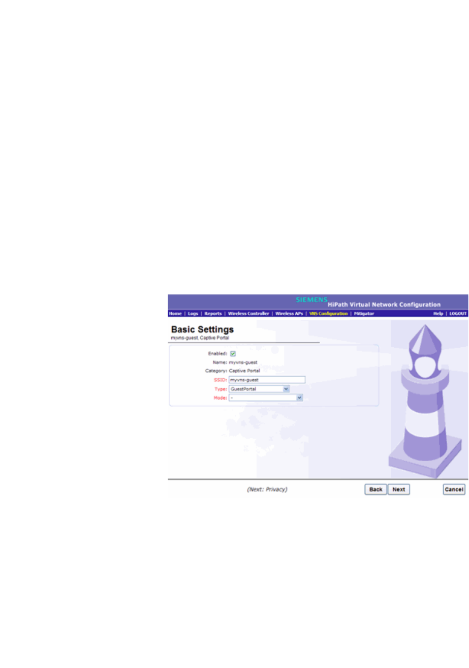
hwc_vnsconfiguration.fm
Configuring a VNS
Working with a GuestPortal VNS
9034530-02, March 2010
HiPath Wireless Controller, Access Points and Convergence Software V7.11, User Guide 287
3. Click on the VNS you want to configure as a GuestPortal VNS. The VNS
configuration window Core tab is displayed.
4. Select a preconfigured WLAN Service and click Edit, or press New to create
a new WLAN Service.
5. In the Edit WLAN Service window, click the Auth & Acct tab.
6. In the Authentication Mode drop-down list, click GuestPortal.
7. To save your changes, click Save.
To create a new GuestPortal VNS using the VNS wizard:
1. From the main menu, click Virtual Network Configuration. The Virtual
Network Configuration screen is displayed.
2. In the left pane, expand the New pane, then click START VNS WIZARD. The
VNS Creation Wizard screen is displayed.
3. In the Name box, type a name for the GuestPortal VNS.
4. In the Category drop-down list, click Captive Portal, and then click Next.
The Basic Settings screen is displayed.
5. Configure the VNS basic settings:
• Enabled – By default, the Enabled checkbox for the new VNS is enabled.
A VNS must be enabled for it to be able to provide service for mobile user
traffic.
•Type – In the drop-down list, click GuestPortal.
• Mode – In the drop-down list, click one of the following the VNS modes:
• Routed – User traffic is tunneled to the HiPath Wireless Controller.

Configuring a VNS
hwc_vnsconfiguration.fm
Working with a GuestPortal VNS
9034530-02, March 2010
288 HiPath Wireless Controller, Access Points and Convergence Software V7.11, User Guide
–In the Gateway box, type the HiPath Wireless Controller's own IP
address in that VNS. This IP address is the default gateway for the
VNS. The HiPath Wireless Controller advertises this address to the
wireless devices when they sign on. For routed VNSs, it corresponds
to the IP address that is communicated to mobile users (in the VNS)
as the default gateway for the VNS subnet. (Mobile users target the
HiPath Wireless Controller's interface in their effort to route packets
to an external host).
– In the Mask box, type the appropriate subnet mask for this IP address
to separate the network portion from the host portion of the address
(typically 255.255.255.0).
• Bridge Traffic Locally at the HWC – User traffic is tunneled to the
HiPath Wireless Controller and is directly bridged at the controller to
a specific VLAN. With this VNS type, mobile users become a natural
extension of a VLAN subnet. For each Bridge Traffic Locally at HWC
VNS that is created, a VLAN needs to be specified. In addition, the
network port on which the VLAN is assigned must be configured on
the switch, and the corresponding HiPath Wireless Controller
interface must match the correct VLAN.
–In the Interface drop-down list, click the physical interface that
provides the access to the VLAN.
–In the Interface IP address box, type the IP address of the HiPath
Wireless Controller’s interface on the VLAN.
– In the Mask box, type the appropriate subnet mask for this IP address
to separate the network portion from the host portion of the address
(typically 255.255.255.0).
– In the VLAN ID box, type the VLAN tag to which the HiPath Wireless
Controller will be bridged for the VNS.
– If applicable, select the Enable DHCP checkbox.
6. Click Next. The DHCP screen is displayed.
If DHCP is disabled, continue with step 11 on page 290. The Filtering screen
is displayed.
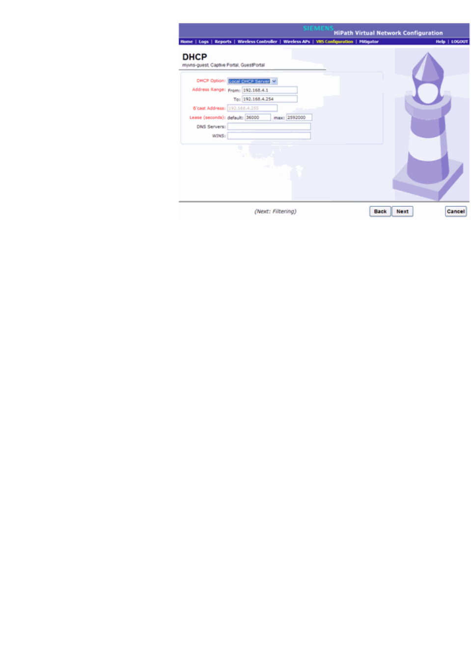
hwc_vnsconfiguration.fm
Configuring a VNS
Working with a GuestPortal VNS
9034530-02, March 2010
HiPath Wireless Controller, Access Points and Convergence Software V7.11, User Guide 289
7. Configure the DHCP settings. In the DHCP Option drop-down list, click one
of the following:
• Use DHCP Relay – Using DHCP relay forces the HiPath Wireless
Controller to forward DHCP requests to an external DHCP server on the
enterprise network. DHCP relay bypasses the local DHCP server for the
HiPath Wireless Controller and allows the enterprise to manage IP
address allocation to a VNS from its existing infrastructure.
•DHCP Servers – Type the IP address of the DHCP server to which
DHCP discover and request messages will be forwarded for clients on
this VNS. The HiPath Wireless Controller does not handle DHCP
requests from users, but instead forwards the requests to the
indicated DHCP server.
The DHCP server must be configured to match the VNS settings. In
particular for a Routed VNS, the DHCP server must identify the
HiPath Wireless Controller's interface IP as the default Gateway
(router) for the subnet. (Users intending to reach devices outside of
the subnet will forward the packets to the default gateway (controller)
for delivery upstream.)
• Local DHCP Server – If applicable, edit the local DHCP server settings.
8. In the DNS Servers box, type the IP Address of the Domain Name Servers
to be used.
9. In the WINS box, type the IP address if the DHCP server uses Windows
Internet Naming Service (WINS).
10. Click Next. The Filtering screen is displayed.
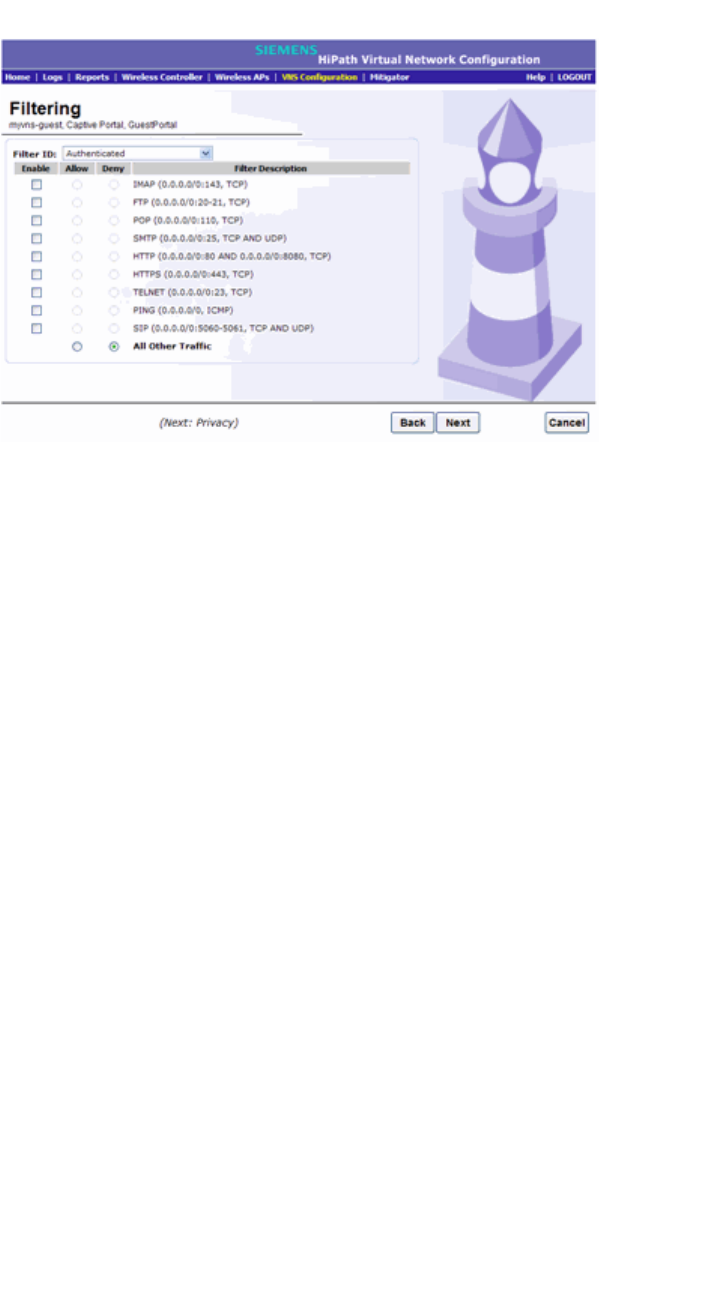
Configuring a VNS
hwc_vnsconfiguration.fm
Working with a GuestPortal VNS
9034530-02, March 2010
290 HiPath Wireless Controller, Access Points and Convergence Software V7.11, User Guide
11. Configure the VNS filtering settings:
12. In the Filter ID drop-down list, click one of the following:
• Authenticated – Controls network access after the user has been
authenticated.
• Non-authenticated – Controls network access and to direct users to a
Captive Portal Web page for login.
13. In the Filter table, select the Enable checkbox for the desired filters, then
select the Allow or Deny option buttons for each filter as needed.
14. At the bottom of the Filter list, select Allow or Deny for All Other Traffic.
15. Click Next. The Privacy screen is displayed.
16. Configure the VNS Privacy settings:
• None – Select if you do not want to assign any privacy mechanism.
• Static Keys (WEP) – Select to use keys on the VNS that match the WEP
mechanism used on the rest of the network. Each AP can participate in
up to 50 VNSs. For each VNS, only one WEP key can be specified. It is
treated as the first key in a list of WEP keys.
•From the WEP Key Length drop-down list, click the WEP encryption
key length: 64 bit, 128 bit, or 152 bit.
• Input Method – Select one of the following:
• Input Hex – If you select Input Hex, type the WEP key input in the
WEP Key box. The key is generated automatically, based on the
input.

hwc_vnsconfiguration.fm
Configuring a VNS
Working with a GuestPortal VNS
9034530-02, March 2010
HiPath Wireless Controller, Access Points and Convergence Software V7.11, User Guide 291
• Input String – If you select Input String, type the secret WEP key
string used for encrypting and decrypting in the Strings box. The
WEP Key box is automatically filled by the corresponding Hex code.
•WPA-PSK – Select to use a Pre-Shared Key (PSK), or shared secret for
authentication. WPA-PSK (Wi-Fi Protected Access Pre-Shared key) is a
security solution that adds authentication to enhanced WEP encryption
and key management. WPA-PSK mode does not require an
authentication server. It is suitable for home or small office.
•To enable WPA v1 encryption, select WPA v.1. If WPA v.1 is enabled,
click one of the following encryption types from the Encryption drop-
down list:
•Auto – The AP will advertise both TKIP and CCMP (Counter Mode
with Cipher Block Chaining Message Authentication Code Protocol)
for WPAv1. CCMP is an IEEE 802.11i encryption protocol that uses
the encryption cipher AES (Advanced Encryption Standard). Auto is
the default.
• TKIP only – The AP will advertise TKIP as an available encryption
protocol for WPAv1. It will not advertise CCMP.
•To enable WPA v2-type encryption, select WPA v.2. The other options for
this drop-down list are:
•Auto – If you click Auto, the Wireless AP advertises both TKIP and
CCMP (counter mode with cipher block chaining message
authentication code protocol). CCMP is an IEEE 802.11i encryption
protocol that uses the encryption cipher AES (Advanced Encryption
Standard). Auto is the default.
• AES only – If you click AES, the Wireless AP advertises CCMP as an
available encryption protocol. It will not advertise TKIP.
•To enable re-keying after a time interval, select Broadcast re-key
interval. If this checkbox is not selected, the Broadcast encryption key is
never changed and the Wireless AP will always use the same broadcast
key for Broadcast/Multicast transmissions. This will reduce the level of
security for wireless communications.
•In the Broadcast re-key interval box, type the time interval after which
the broadcast encryption key is changed automatically. The default is
3600.
•In the Pre-shared key box, type the shared secret key to be used
between the wireless device and Wireless AP. The shared secret key is
used to generate the 256-bit key.
• Mask/Unmask – Click to display or hide your shared secret key.
17. Click Next. The Radio Assignment screen is displayed.
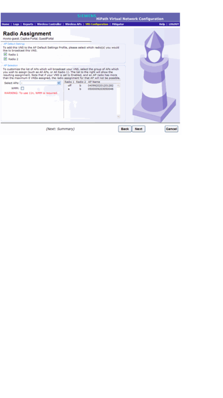
Configuring a VNS
hwc_vnsconfiguration.fm
Working with a GuestPortal VNS
9034530-02, March 2010
292 HiPath Wireless Controller, Access Points and Convergence Software V7.11, User Guide
18. Configure the radio assignments:
•In the AP Default Settings section, select the radios of the AP default
settings profile that you want to broadcast the VNS.
•In the AP Selection section, select the group of APs that will broadcast
the VNS:
• all radios – Click to assign all of the APs’ radios.
• radio 1 – Click to assign only the APs’ Radio 1.
• radio 2– Click to assign only the APs’ Radio 2.
• local APs - all radios – Click to assign only the local APs.
• local APs - radio 1 – Click to assign only the local APs’ Radio 1.
• local APs - radio 2 – Click to assign only the local APs’ Radio 2.
• foreign APs - all radios – Click to assign only the foreign APs.
• foreign APs - radio 1 – Click to assign only the foreign APs’ Radio 1.
• foreign APs - radio 2 – Click to assign only the foreign APs’ Radio 2.
•If applicable, select the WMM checkbox. WMM (Wi-Fi Multimedia), if
enabled on an individual VNS, provides multimedia enhancements that
improve the user experience for audio, video, and voice applications.
WMM is part of the 802.11e standard for QoS. If enabled, the AP will
accept WMM client associations, and will classify and prioritize the
downlink traffic for all WMM clients. WMM clients will also classify and
prioritize the uplink traffic.
19. Click Next. The Summary screen is displayed.
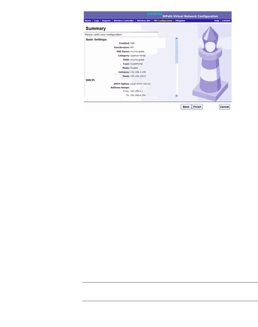
hwc_vnsconfiguration.fm
Configuring a VNS
Creating a VNS using the advanced method
9034530-02, March 2010
HiPath Wireless Controller, Access Points and Convergence Software V7.11, User Guide 293
20. Confirm your VNS configuration. To revise your configuration, click Back.
21. To create your VNS, click Finish, and then click Close.
If the HiPath Wireless Controller is configured to be part of an availability pair,
you can chose to synchronize the VNS on the secondary HiPath Wireless
Controller.
22. If applicable, you can continue to configure or edit the new VNS by clicking
the individual VNS configuration tabs.
6.6 Creating a VNS using the advanced method
Advanced configuration allows administrators to create a new VNS once the
topology, policy, and WLAN services required by the VNS parameters are
available. The topology, policy and WLAN services could be created in advance
or could be created at the time of VNS configuration.
When you create a new VNS, additional tabs are displayed depending on the
selections made in the Core box of the main VNS configuration tab..
When configuring a VNS, you can navigate between the various VNS tabs and
define your configuration without having to save your changes on each individual
tab. After your VNS configuration is complete, click Save on any VNS tab to save
your complete VNS configuration.
Note: If you navigate away from the VNS Configuration tabs without saving your
VNS changes, your VNS configuration changes will be lost.

Configuring a VNS
hwc_vnsconfiguration.fm
Working with existing VNSs
9034530-02, March 2010
294 HiPath Wireless Controller, Access Points and Convergence Software V7.11, User Guide
The following procedure lists the steps necessary to create a VNS in advanced
mode. Each step references a section in this document that describes the full
details. Follow the links provided to go directly to the appropriate sections.
To create a VNS using advanced configuration:
1. From the main menu, click Virtual Network Configuration. The Virtual
Network Configuration screen is displayed.
2. In the left pane, expand the Virtual Networks pane and select an existing
VNS to edit, or click the New button.
3. Enter a name for the VNS.
4. Select an existing WLAN Service for the VNS, or create a new WLAN Service,
or edit an existing one.
For more information, see Section 6.9, “Configuring WLAN Services”, on
page 308.
5. Configure the Default Policies for the VNS. Select existing policies, or create
new policies, or edit existing ones.
For more information, see:
•Section 6.10, “Configuring Policy”, on page 350.
•Section 6.8, “Configuring a Topology”, on page 296.
6. Configure the Status parameters for the VNS:
•Synchronize – Enable automatic synchronization with its availability
peer. Refer to Section 6.2.7, “Using the Sync Summary”, on page 256 for
information about viewing synchronization status. If this VNS is part of an
availability pair, it is recommended that you enable this feature.
• Restrict Policy Set – This feature provides backward compatibility for
legacy VNSs that were upgraded from software releases prior to V7.0.
When it is enabled, the controller respects the prior hierarchical view of
parent/child VNSs and maps external references to properly named (that
is, hierarchically named) Policies.
•Enabled – Check to enable the VNS.
7. Click Save to save your changes.
6.7 Working with existing VNSs
When you work with an existing VNS, you can do the following:
•Enabling and disabling a VNS
•Renaming a VNS

hwc_vnsconfiguration.fm
Configuring a VNS
Working with existing VNSs
9034530-02, March 2010
HiPath Wireless Controller, Access Points and Convergence Software V7.11, User Guide 295
•Deleting a VNS
Also, as with creating a new VNS, you can:
•Configure a topology for the VNS
•Configure a policy for the VNS
•Configure WLAN services for the VNS
•Configure additional policies for the VNS
6.7.1 Enabling and disabling a VNS
By default, when a new VNS is created, the VNS is added to the system as an
enabled VNS. A VNS can be enabled or disabled. Disabling a VNS provides the
ability to temporarily stop wireless service on a VNS. The disabled VNS
configuration remains in the database for future use.
A HiPath Wireless Controller can support the following VNSs:
To enable or disable a VNS:
1. From the main menu, click Virtual Network Configuration. The Virtual
Network Configuration screen is displayed.
2. In the left pane expand the Virtual Networks pane, then select the VNS you
want to either enable or disable.
3. On the Core tab, in the Status box, select or de-select the Enabled checkbox.
4. Click Save. The VNS is enabled or disabled accordingly.
Platform Active VNSs Defined VNSs
C5110 128 256
C4110 64 128
C2400 64 128
C20/C20N 8 16
CRBT8210 16 32
CRBT8110 8 16
Table 21 HiPath Wireless Controller active and defined VNS support

Configuring a VNS
hwc_vnsconfiguration.fm
Configuring a Topology
9034530-02, March 2010
296 HiPath Wireless Controller, Access Points and Convergence Software V7.11, User Guide
6.7.2 Renaming a VNS
To rename a VNS:
1. From the main menu, click Virtual Network Configuration. The Virtual
Network Configuration screen is displayed.
2. In the left pane expand the Virtual Networks pane, then select the VNS you
want to rename.
3. On the Core tab, in the VNS Name field, enter the new name.
4. Click Save. The VNS is renamed.
6.7.3 Deleting a VNS
You can delete a VNS that is no longer necessary.
To delete a VNS:
1. From the main menu, click Virtual Network Configuration. The Virtual
Network Configuration screen is displayed.
2. In the left pane expand the Virtual Networks pane, then select the VNS you
want to rename.
3. On the Core tab, click the Delete button. A pop-up window prompts you to
confirm you want to delete the VNS. Click OK.
4. Click Save. The VNS is deleted.
6.8 Configuring a Topology
Topology configuration is independent of the WLAN services or Policies that are
defined in the system. You can navigate to the Topology configuration page from
either Wireless Controller Configuration or Virtual Network Configuration options
of the HiPath Wireless Assistant main menu. Also, the Policy definition page
allows the user to edit or create a Topology definition at any time.
Topologies are not activated until they are referenced by a Policy. Creating an
interface on a VLAN will not take effect until a Policy references its usage.
Topologies cannot be deleted while they are active (that is, referenced by a
Policy).
On the Topology configuration page, the key field is the Mode, which determines
some of the other factors of the topology. When you have completed defining the
topology for your VNS, save the topology settings. Once your topology is saved,
you can then access the remaining VNS tabs and continue configuring your VNS.

hwc_vnsconfiguration.fm
Configuring a VNS
Configuring a Topology
9034530-02, March 2010
HiPath Wireless Controller, Access Points and Convergence Software V7.11, User Guide 297
On the Topology configuration page, a number of parameters related to network
topology can be defined:
•VLAN ID and associated L2 port
•L3 (IP) interface presence and the associated IP address and subnet range
•The rules for using DHCP
•Enabling or disabling the use of the associated interface for
management/control traffic
•Selection of an interface for AP registration
•Multicast filter definition
•Exception filter definition.
6.8.1 Configuring a basic topology
The configuration procedure below is sufficient to create and be able to save a
new Topology. Optional configuration options are described in the following
sections.
To configure a basic topology:
1. From the main menu, click either Wireless Controller Configuration or
Virtual Network Configuration. Then, in the left pane, select Topology. The
Topologies window displays.
2. If you want to edit an existing topology, select the desired topology. If you
want to create a new topology, click the New button. Depending on your
selection, two or three tabs are displayed.
3. On the General tab, enter a name for the topology in the Name field.
4. Select a mode of operation from the Mode drop-down list. Choices are:
• Routed – Routed topologies do not need any Layer 2 configuration, but
do require Layer 3 configuration. See Section 6.8.2, “Layer 3
configuration”, on page 299 for more information.
• Bridge Traffic Locally at AP – Requires Layer 2 configuration. Does not
require Layer 3 configuration. Bridge Traffic at the AP VNSs do not
require the definition of a corresponding IP address since all traffic for
users in that VNS will be directly bridged by the Wireless AP at the local
network point of attachment (VLAN at AP port).

Configuring a VNS
hwc_vnsconfiguration.fm
Configuring a Topology
9034530-02, March 2010
298 HiPath Wireless Controller, Access Points and Convergence Software V7.11, User Guide
• Bridge Traffic Locally at HWC – Requires Layer 2 configuration. May
optionally have Layer 3 configuration. Layer 3 configuration would be
necessary if services (such as DHCP, captive portal, etc.) are required
over the configured network segment, or if controller management
operations are intended to be done through the configured interface.
5. Configure the Layer 2 parameters, depending on the previously selected
Mode.
•For Bridge Traffic Locally at HWC, enter a VLAN identifier that is valid
for your system and enter the port to which this VLAN is attached to,
according to the networking deployment model pre-established during
planning.
•For Bridge Traffic Locally at AP, enter a VLAN identifier that is valid for
your system, and specify whether the VLAN configuration is Tagged or
Untagged.
6. Click Save to save your changes.
These steps are sufficient to create and save a topology. The following
configuration options are optional and depend on the mode of the topology.
6.8.1.1 Physical Port Topologies
Starting with V7.0, "Physical Ports" refers to the data plane physical ports. The
attributes of a physical port are:
•Administrative status (read-write)
•Name (read-only)
•MAC address (read-only)
•MTU size
•Multicast Support for Routed VNS
Physical port topologies are pre-defined by the HiPath Wireless Controller and
cannot be removed from the HiPath Wireless Controller configuration. By default,
all physical ports are set with multicast support for Routed VNS disabled. At most,
one non-management plane port can be enabled for the multicast support for
Routed VNS. This can be configured on the new physical port GUI.
6.8.1.2 Enabling management traffic
If management traffic is enabled for a VNS, it overrides the built-in exception
filters that prohibit traffic on the HiPath Wireless Controller data interfaces. For
more information, see Section 6.10, “Configuring Policy”, on page 350.

hwc_vnsconfiguration.fm
Configuring a VNS
Configuring a Topology
9034530-02, March 2010
HiPath Wireless Controller, Access Points and Convergence Software V7.11, User Guide 299
To enable management traffic for a topology:
1. From the main menu, click either Wireless Controller Configuration or
Virtual Network Configuration. Then, in the left pane, select Topology or
Topologies. The Topologies window displays.
2. Select the desired physical or routed topology. If the Layer 3 parameters are
not displayed, check the Layer 3 checkbox.
3. Select the Management Traffic checkbox.
4. To save your changes, click Save.
6.8.2 Layer 3 configuration
This section describes configuring IP addresses, DHCP options, Next Hop and
OSPF parameters, for Physical port, Routed, and Bridge Traffic Locally at HWC
topologies.
6.8.2.1 IP address configuration
The L3 (IP) address definition is only required for Physical port and Routed
topologies. For Bridge Traffic Locally at HWC topologies, L3 configuration is
optional. L3 configuration would be necessary if services (such as DHCP, captive
portal, etc.) are required over the configured network segment or if controller
management operations are intended to be done through the configured
interface.
Bridge Traffic Locally at AP VNSs do not require the definition of a corresponding
IP address since all traffic for users in that VNS will be directly bridged by the
Wireless AP at the local network point of attachment (VLAN at AP port).
To define the IP address for the topology:
1. From the main menu, click Wireless Controller Configuration and then
from the left pane select Topology. Alternatively, from the main menu select
Virtual Network Configuration and then press Topologies button.
2. If already defined, click the topology you want to define the IP address for.
The Topology window is displayed. Alternatively, press the New button to
create a new topology. Depending on the preselected options, two or three
tabs are displayed.
3. For IP interface configuration for Routed topologies, configure the following
Layer 3 parameters.
a) In the Gateway field, type the HiPath Wireless Controller's own IP
address in that VNS. This IP address is the default gateway for the VNS.
The HiPath Wireless Controller advertises this address to the wireless

Configuring a VNS
hwc_vnsconfiguration.fm
Configuring a Topology
9034530-02, March 2010
300 HiPath Wireless Controller, Access Points and Convergence Software V7.11, User Guide
devices when they sign on. For routed VNSs, it corresponds to the IP
address that is communicated to MUs (in the VNS) as the default gateway
for the VNS subnet. (MUs target the HiPath Wireless Controller's
interface in their effort to route packets to an external host).
b) In the Mask field, type the appropriate subnet mask for the IP address. to
separate the network portion from the host portion of the address
(typically, 255.255.255.0).
c) If necessary, configure the MTU value. Typically, you will not change this
value from the default.
d) If desired, enable Management traffic.
4. For IP interface configuration for Bridge Traffic Locally at HWC topologies,
configure the following Layer 3 parameters.
a) In the Interface IP field, type the IP address that corresponds to the
HiPath Wireless Controller's own point of presence on the VLAN. In this
case, the controller's interface is typically not the gateway for the subnet.
The gateway for the subnet is the infrastructure router defined to handle
the VLAN.
b) In the Mask field, type the appropriate subnet mask for the IP address. to
separate the network portion from the host portion of the address
(typically, 255.255.255.0).
c) Configure Strict Sunbnet Adherence.
d) If necessary, configure the MTU value. Typically, you will not change this
value from the default.
e) If desired, configure AP Registration. If selected, Wireless APs can use
this port for discovery and registration.
f) If desired, enable Management traffic.
6.8.2.2 DHCP configuration
On the Topology page, define parameters for DHCP.
DHCP IP assignment is not applicable to Bridge Traffic Locally at AP mode
since all traffic for users in that VNS will be directly bridged by the Wireless AP at
the local network point of attachment (VLAN at AP port). DHCP assignment is
disabled by default for Bridged to VLAN mode. However, you can enable DHCP
server/relay functionality to have the controller service the IP addresses for the
VLAN (and wireless users).

hwc_vnsconfiguration.fm
Configuring a VNS
Configuring a Topology
9034530-02, March 2010
HiPath Wireless Controller, Access Points and Convergence Software V7.11, User Guide 301
To configure DHCP options:
1. On the Topology page, from the DHCP drop-down list, select one of the
following options and click the Configure button.
•Local Server if the HiPath Wireless Controller's local DHCP server is
used for managing IP address allocation.
• Use Relay if the HiPath Wireless Controller forwards DHCP requests to
an external DHCP server on the enterprise network. DHCP relay
bypasses the local DHCP server for the HiPath Wireless Controller and
allows the enterprise to manage IP address allocation to a VNS from its
existing infrastructure.
2. If you selected Local Server, the following window displays. Configure the
following parameters:
a) In the Domain Name box, type the external enterprise domain name
server to be used.
b) In the Lease default box, type the default time limit. The default time limit
dictates how long a wireless device can keep the DHCP server assigned
IP address. The default value is 36000 seconds (10 hours).
c) In the DNS Servers box, type the IP Address of the Domain Name
Servers to be used.
d) In the WINS box, type the IP address if the DHCP server uses Windows
Internet Naming Service (WINS).
e) Check the Enable DLS DHCP Option checkbox if you expect optiPoint
WL2 wireless phone traffic on the VNS. HiPath DLS (HiPath Deployment
Service) is an application that provides configuration management and
software deployment and licensing for optiPoint WL2 phones. For more
information, see Appendix C, “optiPoint WL2 Configuration”.
f) In the Gateway field, type the HiPath Wireless Controller’s own IP
address in that topology. This IP address This IP address is the default
gateway for the topology. The HiPath Wireless Controller advertises this
address to the wireless devices when they sign on. For routed topologies,
it corresponds to the IP address that is communicated to Wireless clients
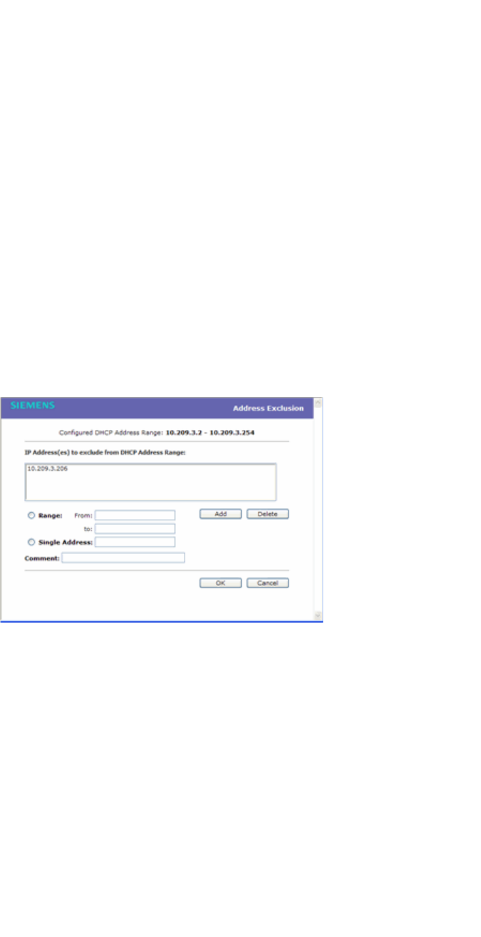
Configuring a VNS
hwc_vnsconfiguration.fm
Configuring a Topology
9034530-02, March 2010
302 HiPath Wireless Controller, Access Points and Convergence Software V7.11, User Guide
as the default gateway for the subnet. (wireless clients target the HiPath
Wireless Controller's interface in their effort to route packets to an
external host).
For a Bridge traffic locally at the HWC topology, the IP address
corresponds to the HiPath Wireless Controller's own point of presence on
the VLAN. In this case, the controller's interface is typically not the
gateway for the subnet. The gateway for the subnet is the infrastructure
router defined to handle the VLAN.
g) The Address Range boxes (from and to) populate automatically with the
range of IP addresses to be assigned to wireless devices using this VNS,
based on the IP address you provided.
•To modify the address in the Address Range from box, type the first
available address.
•To modify the address in the Address Range to box, type the last
available address.
•If there are specific IP addresses to be excluded from this range, click
Exclusion(s). The DHCP Address Exclusion dialog is displayed.
•In the DHCP Address Exclusion dialog, do one of the following:
– To specify an IP range, type the first available address in the From
box and type the last available address in the to box. Click Add for
each IP range you provide.
– To specify an IP address, select the Single Address option and type
the IP address in the box. Click Add for each IP address you provide.
– To save your changes, click OK. The DHCP Address Exclusion dialog
closes.
h) The Broadcast Address box populates automatically based on the
Gateway IP address and subnet mask of the VNS.
i) Click Close.

hwc_vnsconfiguration.fm
Configuring a VNS
Configuring a Topology
9034530-02, March 2010
HiPath Wireless Controller, Access Points and Convergence Software V7.11, User Guide 303
3. If you selected Use Relay, the following window displays.
a) in the DHCP Servers box, type the IP address of the DHCP server to
which DHCP discover and request messages will be forwarded for clients
on this VNS. The HiPath Wireless Controller does not handle DHCP
requests from users, but instead forwards the requests to the indicated
DHCP server.
Note: The DHCP Server must be configured to match the topology settings.
In particular for Routed topologies, the DHCP server must identify the HiPath
Wireless Controller's interface IP as the default Gateway (router) for the
subnet. (Users intending to reach devices outside of the subnet will forward
the packets to the default gateway (controller) for delivery upstream.)
4. To save your changes, click Save.
6.8.2.3 Defining a next hop route and OSPF advertisement
The next hop definition allows the administrator to define a specific host as the
target for all non-VNS targeted traffic for users in a VNS. The next hop IP
identifies the target device to which all VNS (user traffic) will be forwarded to.
Next-hop definition supersedes any other possible definition in the routing table.
If the traffic destination from a wireless device on a VNS is outside of the VNS, it
is forwarded to the next hop IP address, where this router applies policy and
forwards the traffic. This feature applies to unicast traffic only. In addition, you can
also modify the Open Shortest Path First (OSPF) route cost.
OSPF is an interior gateway routing protocol developed for IP networks based on
the shortest path first or link-state algorithm. Using OSPF, a host that obtains a
change to a routing table or detects a change in the network immediately
distributes the information to all other hosts in the network so that all will have the
same routing table information. The host using OSPF sends only the part that has
changed, and only when a change has taken place.
To define a next hop route and OSPF advertisement:
1. From the main menu, click Virtual Network Configuration. The Virtual
Network Configuration screen is displayed.
2. In the left pane, expand the Topologies pane, then click the routed Topology
you want to define a next-hop route for. The Topology tab is displayed.
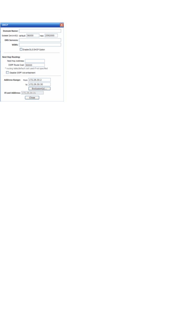
Configuring a VNS
hwc_vnsconfiguration.fm
Configuring a Topology
9034530-02, March 2010
304 HiPath Wireless Controller, Access Points and Convergence Software V7.11, User Guide
3. In the Layer 3 area, click the Configure button. The DHCP configuration
dialog window displays.
4. In the Next Hop Address box, type the IP address of the next hop router on
the network through which you wish all traffic on the VNS using this Topology
to be directed.
5. In the OSPF Route Cost box, type the OSPF cost of reaching the VNS
subnet.
The OSPF cost value provides a relative cost indication to allow upstream
routers to calculate whether or not to use the HiPath Wireless Controller as a
better fit or lowest cost path to reach devices in a particular network. The
higher the cost, the less likely of the possibility that the HiPath Wireless
Controller will be chosen as a route for traffic, unless that HiPath Wireless
Controller is the only possible route for that traffic.
6. To disable OSPF advertisement on this VNS, select the Disable OSPF
Advertisement checkbox.
7. Click Close.
8. To save your changes, click Save.
6.8.3 Exception filtering
The exception filter provides a set of rules aimed at restricting the type of traffic
that is delivered to the controller. By default, your system is shipped with a set of
restrictive filtering rules that help control access through the interfaces to only
absolutely necessary services.
By configuring to allow management on an interface, an additional set of rules is
added to the shipped filter rules that provide access to the system's management
configuration framework (SSH, HTTPS, SNMP Agent). Most of this functionality

hwc_vnsconfiguration.fm
Configuring a VNS
Configuring a Topology
9034530-02, March 2010
HiPath Wireless Controller, Access Points and Convergence Software V7.11, User Guide 305
is handled directly behind the scenes by the system, rolling and un-rolling canned
filters as the system's topology and defined access privileges for an interface
change.
Note: An interface for which Allow Management is enabled, can be reached by
any other interface. By default, Allow Management is disabled and shipped
interface filters will only permit the interface to be visible directly from it's own
subnet.
The visible exception filter definitions, both in physical ports and topology
definitions, allow administrators to define a set of rules to be prepended to the
system's dynamically updated exception filter protection rules. Rule evaluation is
performed top to bottom, until an exact match is determined. Therefore, these
user-defined rules are evaluated before the system’s own generated rules. As
such, these user-defined rules may inadvertently create security lapses in the
system's protection mechanism or create a scenario that filters out packets that
are required by the system.
Note: Use exception filters only if absolutely necessary. It is recommended to
avoid defining general allow all or deny all rule definitions since those definitions
can easily be too liberal or too restrictive to all types of traffic.
The exception rules are evaluated in the context of referring to the specific
controller's interface. The destination address for the filter rule definition is
typically defined as the interface's own IP address. The port number for the filter
definition corresponds to the target (destination) port number for the applicable
service running on the controller's management plane.
The exception filter on an topoloty applies only to the destination portion of the
packet. Traffic to a specified IP address and IP port is either allowed or denied.
Adding exception filtering rules allows network administrators to either tighten or
relax the built-in filtering that automatically drops packets not specifically allowed
by filtering rule definitions. The exception filtering rules can deny access in the
event of a DoS attack, or can allow certain types of management traffic that would
otherwise be denied. Typically, Allow Management is enabled.
To define exception filters:
1. On the Topology page, click the Exception Filters tab.
2. To add a new filter, click the Add button.
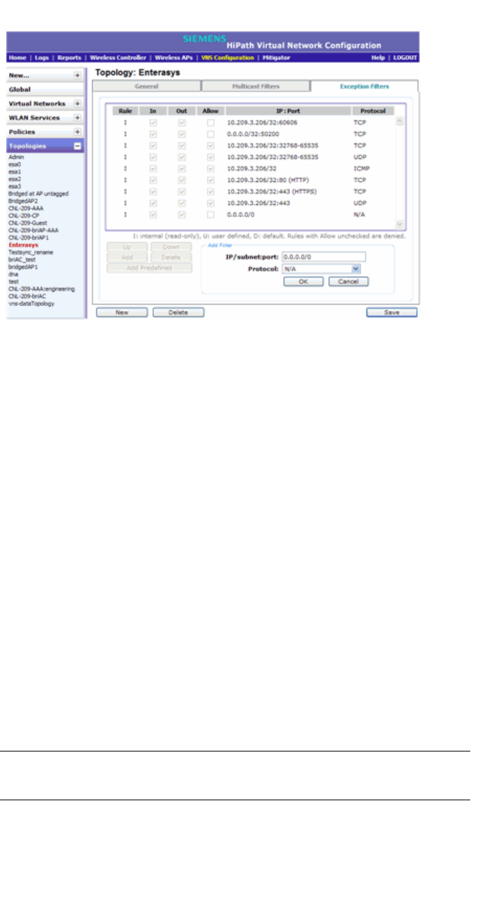
Configuring a VNS
hwc_vnsconfiguration.fm
Configuring a Topology
9034530-02, March 2010
306 HiPath Wireless Controller, Access Points and Convergence Software V7.11, User Guide
3. For each filtering rule you are defining, do the following:
•In the IP/subnet:port box, type the destination IP address. You can also
specify an IP range, a port designation, or a port range on that IP address.
•In the Protocol drop-down list, click the applicable protocol. The default
is N/A.
•Click OK to add the user-defined rule to the rule table.
4. To add a predefined filter, click the Add Predefined button, then select the
desired filter from the drop-down list. Click Add to add the rule to the rule
table.
5. By default, user-defined rules are enabled on ingress (In) and egress (Out),
and are assumed to be Allow rules. To disable the rule in either direction, or
to make it a Deny rule, click the new filter, then de-select the relevant
checkbox.
6. To edit the order of filters, click the filter, and then click the Up and Down
buttons. The filtering rules are executed in the order you define here.
7. To delete a user-defined rule, click the filter, then click the Delete button.
8. To save your changes, click Save.
Note: For external Captive Portal, you need to add an external server to a
non-authentication filter.
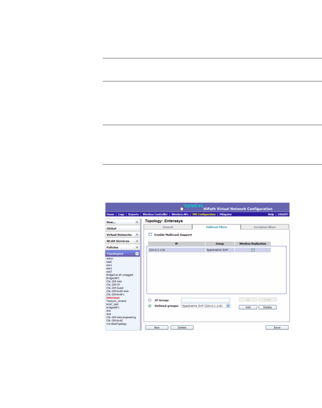
hwc_vnsconfiguration.fm
Configuring a VNS
Configuring a Topology
9034530-02, March 2010
HiPath Wireless Controller, Access Points and Convergence Software V7.11, User Guide 307
6.8.4 Multicast filtering
A mechanism that supports multicast traffic can be enabled as part of a topoloty
definition. This mechanism is provided to support the demands of VoIP and IPTV
network traffic, while still providing the network access control.
Note: To use the mobility feature with this topology, you must select the Enable
Multicast Support checkbox for the data port.
Define a list of multicast groups whose traffic is allowed to be forwarded to and
from the VNS using this topology. The default behavior is to drop the packets. For
each group defined, you can enable Multicast Replication by group.
Note: Before enabling multicast filters and depending on the topology, you may
need to define which physical interface to use for multicast relay. Define the
multicast port on the IP Addresses tab. For more information, see Section 3.4.3,
“Setting up the data ports”, on page 54.
To enable multicast for a topology:
1. On the Topology page, click the Multicast Filters tab.
2. To enable the multicast function, select Enable Multicast Support.
3. Define the multicast groups by selecting one of the radio buttons:
•IP Group – Type the IP address range.
• Defined groups – Click from the drop-down list.
4. Click Add. The group is added to the list above.

Configuring a VNS
hwc_vnsconfiguration.fm
Configuring WLAN Services
9034530-02, March 2010
308 HiPath Wireless Controller, Access Points and Convergence Software V7.11, User Guide
5. To enable the wireless multicast replication for this group, select the
corresponding Wireless Replication checkbox.
6. To modify the priority of the multicast groups, click the group row, and then
click the Up or Down buttons.
A Deny All rule is automatically added as the last rule, IP = *.*.*.* and the
Wireless Replication checkbox is not selected. This rule ensures that all
other traffic is dropped.
7. To save your changes, click Save.
Note: The multicast packet size should not exceed 1450 bytes.
6.9 Configuring WLAN Services
A WLAN Service represents all the RF, authentication and QoS attributes of a
wireless access service. The WLAN Service can be one of three basic types:
•Standard – A conventional service. Only APs running HiPath Wireless
software can be part of this WLAN Service. This type of service is useable as
a Bridged @ Controller, Bridged @ AP, or Routed VNS. This type of service
provides access for mobile stations. Therefore, policies can be assigned to
this type of WLAN service to create a VNS.
•Third Party AP – A wireless service offered by third party APs. This type of
service provides access for mobile stations. Therefore, policies can be
assigned to this type of WLAN service to create a VNS.
•WDS – This represent a group of APs organized into a hierarchy for purposes
of providing a Wireless Distribution Service. This type of service is in essence
a wireless trunking service rather than a service that provides access for
stations. As such this type of service cannot have policies attached to it.
With the introduction of V7.0, the components of the WLAN Service map more or
less completely to the corresponding components of a VNS in V6Rx. The
exception is that WLAN Services are not classified as SSID-based or AAA-based,
as they were in V6Rx. Instead, the administrator makes an explicit choice of the
type of authentication to use on the WLAN Service. If the choice of authentication
option conflicts with any of the other authentication or privacy choices, the WLAN
Service cannot be enabled.

hwc_vnsconfiguration.fm
Configuring a VNS
Configuring WLAN Services
9034530-02, March 2010
HiPath Wireless Controller, Access Points and Convergence Software V7.11, User Guide 309
6.9.1 Configuring a WLAN Service
This section describes how to create a new or edit an existing WLAN Service,
including assigning Wireless APs to the service. Following sections describe how
to configure Privacy, Authentication and Accounting, and QoS for a WLAN
Service.
6.9.1.1 Third-party AP WLAN Service Type
For more information, see Chapter 9, “Working with third-party APs”.
A third-party AP WLAN Service allows for the specification of a segregated
subnet by which non-HiPath Wireless APs are used to provide RF services to
users while still utilizing the HiPath Wireless Controller for user authentication and
user policy enforcement.
Note: Third-party AP devices are not fully integrated with the system and
therefore must be managed individually to provide the correct user access
characteristics.
The definition of third-party AP identification parameters allows the system to be
able to differentiate the third-party AP device (and corresponding traffic) from
user devices on that segment. Devices identified as third-party APs are
considered pre-authenticated, and are not required to complete the
corresponding authentication verification stages defined for users in that segment
(typically Captive Portal enforcement).
In addition, third-party APs have a specific set of filters (third-party) applied to
them by default, which allows the administrator to provide different traffic access
restrictions to the third-party AP devices for the users that use those resources.
The third-party filters could be used to allow access to third-party APs
management operations (for example, HTTP, SNMP).
6.9.1.2 Configuring a basic WLAN Service
To configure a WLAN Service:
1. From the main menu, click either Wireless Controller Configuration or
Virtual Network Configuration. Then, in the left pane, select WLAN
Services. The WLAN Services window displays.
2. If you want to edit an existing service, select the desired service from the left
pane. If you want to create a new service, click the New button. The WLAN
Services configuration window displays.
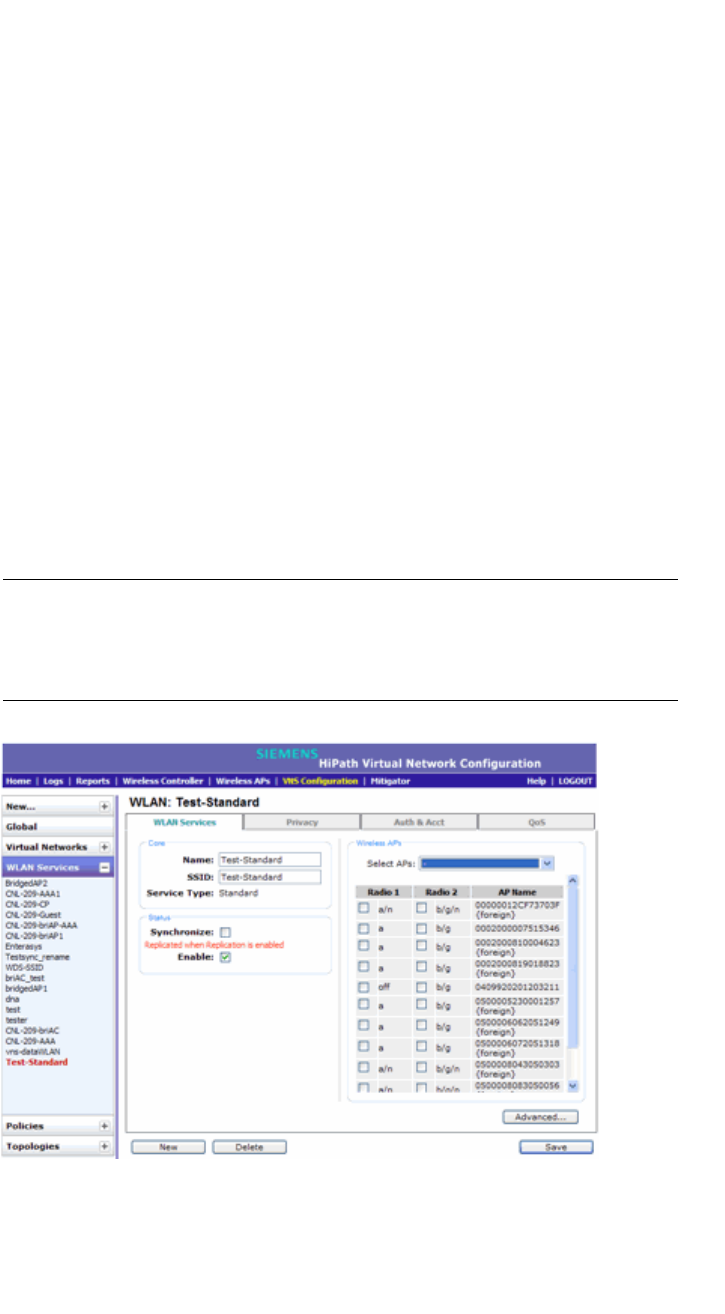
Configuring a VNS
hwc_vnsconfiguration.fm
Configuring WLAN Services
9034530-02, March 2010
310 HiPath Wireless Controller, Access Points and Convergence Software V7.11, User Guide
3. In the Core area, enter the Name and SSID of the service and select the
service Type.
4. In the Status area, select Synchronize if desired. Enabling this feature allows
availability pairs to be automatically synchronized.
5. The service is enabled by default.
6. Click Save. If you are creating a new service, the WLAN Services
configuration window is redisplayed, allowing you to assign Wireless APs to
the service.
6.9.1.3 Assigning Wireless APs to a service
1. If the WLAN Service configuration page is not already displayed, from the
main menu, click either Wireless Controller Configuration or Virtual
Network Configuration. Then, in the left pane, select WLAN Services. The
WLAN Services window displays.
2. Select the desired service to edit from the left pane. The WLAN Service
configuration page is displayed.
Note: If two HiPath Wireless Controllers have been paired for availability (for
more information, see Section 7.1, “Availability”, on page 381), each HiPath
Wireless Controller's registered Wireless APs are displayed as foreign in the
list of available Wireless APs on the other HiPath Wireless Controller.
3. In the Wireless APs area, assign the Wireless APs’ Radios to the service by
selecting the individual radios’ checkboxes..

hwc_vnsconfiguration.fm
Configuring a VNS
Configuring WLAN Services
9034530-02, March 2010
HiPath Wireless Controller, Access Points and Convergence Software V7.11, User Guide 311
You can also use the Select APs list, to select APs and their radios by
grouping:
•all radios – Click to assign all of the APs’ radios.
• radio 1 – Click to assign only the APs’ Radio 1.
• radio 2– Click to assign only the APs’ Radio 2.
• local APs - all radios – Click to assign only the local APs.
•local APs - radio 1 – Click to assign only the local APs’ Radio 1.
•local APs - radio 2 – Click to assign only the local APs’ Radio 2.
• foreign APs - all radios – Click to assign only the foreign APs.
•foreign APs - radio 1 – Click to assign only the foreign APs’ Radio 1.
•foreign APs - radio 2 – Click to assign only the foreign APs’ Radio 2.
• clear all selections – Click to clear all of the AP radio assignments.
• original selections – Click to return to the AP radio selections prior to the
most recent save.
Note: You can assign the Radios of all three Wireless AP variants — HiPath
Wireless AP, HiPath Wireless Outdoor AP, and Wireless 802.11n AP — to
any VNS.
4. Click Advanced. The Advanced dialog is displayed.
5. In the RF area, do the following:
• Suppress SSID – Select to prevent this SSID from appearing in the
beacon message sent by the Wireless AP. The wireless device user
seeking network access will not see this SSID as an available choice, and
will need to specify it.
• Enable 11h support – Select to enable TPC (Transmission Power
Control) reports. By default this option is disabled. It is recommended to
enable this option.
• Apply power reduction to 11h clients – Select to enable the
Wireless AP to use reduced power (as does the 11h client). By default
this option is disabled. It is recommended to enable this option.
• Process client IE requests – Select to enable the Wireless AP to accept
IE requests sent by clients via Probe Request frames and responds by
including the requested IE’s in the corresponding Probe Response
frames. By default this option is disabled. It is recommended to enable
this option.

Configuring a VNS
hwc_vnsconfiguration.fm
Configuring WLAN Services
9034530-02, March 2010
312 HiPath Wireless Controller, Access Points and Convergence Software V7.11, User Guide
6. In the Timeout area, do the following:
•Idle: (pre) – Specify the amount of time in minutes that a Mobile user can
have a session on the controller in pre-autheticated state but no active
traffic is passed. The session will be terminated if no active traffic is
passed within this time. The default value is 5 minutes.
•Idle: (post) – Specify the amount of time in minutes that a Mobile user
can have a session on the controller in authenticated state but no active
traffic is passed. The session will be terminated if no active traffic is
passed within this time. The default value is 30 minutes.
• Session – Specify the maximum number of minutes of service to be
provided to the user before termination of the session.
7. In the Client Behavior area, select the Block Mu to MU traffic checkbox if
you want to prevent two devices associated with this SSID and registered as
users of the controller, to be able to talk to each other. The blocking is
enforced at the L2 (device) classification level.
8. The 802.1D Base Port number in the 802.1D area is the port number by
which NetSight recognizes the SSID. It is read-only.
9. To save your changes, click Save.
You can view the WLAN Services that each radio is assigned to by clicking
the WLAN Assignment tab on the Wireless AP Configuration screen.
Once you have assigned a Wireless AP Radio to eight WLAN Services, it will not
appear in the list for another WLAN Service setup. Each Radio can support up to
eight SSIDs (16 per AP). Each AP can be assigned to any of the VNSs defined
within the system. The HiPath Wireless Controller can support the following
active VNSs:
•C5110 – Up to 128 VNSs
•C4110 – Up to 64 VNSs
•C2400 – Up to 64 VNSs
•C20 – Up to 8 VNSs
•C20N – Up to 8 VNSs
•CRBT8210 – Up to 8 VNSs
•CRBT8110 – Up to 8 VNSs

hwc_vnsconfiguration.fm
Configuring a VNS
Configuring WLAN Services
9034530-02, March 2010
HiPath Wireless Controller, Access Points and Convergence Software V7.11, User Guide 313
6.9.2 Configuring privacy
Privacy is a mechanism that protects data over wireless and wired networks,
usually by encryption techniques. The HiPath Wireless Controller provides
several privacy mechanism to protect data over the WLAN.
There are five privacy options:
• None
• Static Wired Equivalent Privacy (WEP) – Keys for a selected VNS, so that
it matches the WEP mechanism used on the rest of the network. Each AP can
participate in up to 50 VNSs. For each VNS, only one WEP key can be
specified. It is treated as the first key in a list of WEP keys.
• Dynamic Keys – The dynamic key WEP mechanism changes the key for
each user and each session.
• Wi-fi Protected Access (WPA)
– version 1 with encryption by temporal key integrity protocol (TKIP)
– version 2 with encryption by advanced encryption standard with counter-
mode/CBC-MAC protocol (AES-CCMP)
• Wi-Fi Protected Access (WPA) Pre-Shared key (PSK) – Privacy in PSK
mode, using a Pre-Shared Key (PSK), or shared secret for authentication.
WPA-PSK is a security solution that adds authentication to enhanced WEP
encryption and key management. WPA-PSK mode does not require an
authentication server. It is suitable for home or small office.
Note: Regardless of the Wireless AP model or WLAN Service type, a maximum
of 112 simultaneous clients, per radio, are supported by all of the data protection
encryption techniques.
6.9.2.1 About Wi-Fi Protected Access (WPA v1 and WPA v2)
Note: To achieve the strongest encryption protection for your VNS, it is
recommended to use WPA v.1 or WPA v.2.
WPA v1 and WPA v2 add authentication to WEP encryption and key
management. Key features of WPA privacy include:
•Specifies 802.1x with Extensible Authentication Protocol (EAP)
•Requires a RADIUS or other authentication server

Configuring a VNS
hwc_vnsconfiguration.fm
Configuring WLAN Services
9034530-02, March 2010
314 HiPath Wireless Controller, Access Points and Convergence Software V7.11, User Guide
•Uses RADIUS protocols for authentication and key distribution
•Centralizes management of user credentials
The encryption portion of WPA v1 is Temporal Key Integrity Protocol (TKIP). TKIP
includes:
•A per-packet key mixing function that shares a starting key between devices,
and then changes their encryption key for every packet (unicast key) or after
the specified re-key time interval (broadcast key) expires
•An extended WEP key length of 256-bits
•An enhanced Initialization Vector (IV) of 48 bits, instead of 24 bits, making it
more difficult to compromise
•A Message Integrity Check or Code (MIC), an additional 8-byte code that is
inserted before the standard WEP 4-byte Integrity Check Value (ICV). These
integrity codes are used to calculate and compare, between sender and
receiver, the value of all bits in a message, which ensures that the message
has not been tampered with.
The encryption portion of WPA v2 is Advanced Encryption Standard (AES). AES
includes:
•A 128 bit key length, for the WPA2/802.11i implementation of AES
•Four stages that make up one round. Each round is iterated 10 times.
•A per-packet key mixing function that shares a starting key between devices,
and then changes their encryption key for every packet or after the specified
re-key time interval expires.
•The Counter-Mode/CBC-MAC Protocol (CCMP), a new mode of operation for
a block cipher that enables a single key to be used for both encryption and
authentication. The two underlying modes employed in CCM include:
•Counter mode (CTR) that achieves data encryption
•Cipher Block Chaining Message Authentication Code (CBC-MAC) to
provide data integrity
The following is an overview of the WPA authentication and encryption process:
• Step one – The wireless device client associates with Wireless AP.
• Step two – Wireless AP blocks the client's network access while the
authentication process is carried out (the HiPath Wireless Controller sends
the authentication request to the RADIUS authentication server).
• Step three – The wireless client provides credentials that are forwarded by
the HiPath Wireless Controller to the authentication server.
• Step four – If the wireless device client is not authenticated, the wireless
client stays blocked from network access.

hwc_vnsconfiguration.fm
Configuring a VNS
Configuring WLAN Services
9034530-02, March 2010
HiPath Wireless Controller, Access Points and Convergence Software V7.11, User Guide 315
• Step five – If the wireless device client is authenticated, the HiPath Wireless
Controller distributes encryption keys to the Wireless AP and the wireless
client.
•Step six – The wireless device client gains network access via the Wireless
AP, sending and receiving encrypted data. The traffic is controlled with
permissions and policy applied by the HiPath Wireless Controller.
6.9.2.2 Wireless 802.11n APs and WPA authentication
Note: If you configure a WLAN Service to use either WEP or TKIP authentication,
any Wireless 802.11n AP associated to a VNS using that service will be limited to
legacy AP performance rates.
If a VNS is configured to use WPA authentication, any Wireless 802.11n AP within
that VNS will do the following:
•WPA v.1 – If WPA v.1 is enabled, the Wireless 802.11n AP will advertise only
TKIP as an available encryption protocol.
•WPA v.2 – If WPA v.2 is enabled, the Wireless 802.11n AP will do the
following:
•If WPA v.1 is enabled, the Wireless 802.11n AP will advertise TKIP as an
available encryption protocol.
Note: If WPA v.2 is enabled, the Wireless 802.11n AP does not support the
Auto option.
•If WPA v.1 is disabled, the Wireless 802.11n AP will advertise the
encryption cipher AES (Advanced Encryption Standard).
Note: The security encryption for some network cards must not to be set to
WEP or TKIP to achieve a data rate beyond 54 Mbps.
6.9.2.3 WPA Key Management Options
Wi-Fi Protected Access (WPA v1 and WPA v2) Privacy offers you the following
key management options:
•None
•Opportunistic Keying

Configuring a VNS
hwc_vnsconfiguration.fm
Configuring WLAN Services
9034530-02, March 2010
316 HiPath Wireless Controller, Access Points and Convergence Software V7.11, User Guide
•Pre-authentication
•Opportunistic Keying & Pre-auth
The following sections explain the key management options.
None
The wireless client device performs a complete 802.1x authentication each time
it associates or tries to connect to a Wireless AP.
Opportunistic Keying
Opportunistic Keying or opportunistic key caching (OKC) enables the client
devices to roam fast and securely from one Wireless AP to another in 802.1X
authentication setup.
The client devices that run applications such as video streaming and VoIP require
rapid reassociation during roaming. OKC helps such client devices by enabling
them to rapidly reassociate with the Wireless APs. This avoids delays and gaps
in transmission and thus helps in secure fast roaming (SFR).
Note: The client devices should support OKC to use the OKC feature in the
HiPath WLAN.
Pre-authentication
Pre-authentication enables a client device to authenticate simultaneously with
multiple Wireless APs in 802.1X authentication setup. When the client device
roams from one Wireless AP to another, it does not have to perform the complete
802.1X authentication to reassociate with the new Wireless AP as it is already
pre-authenticated with it. This reduces the reassociation time and thus helps in
seamless roaming.
Note: The client devices should support pre-authentication to use the pre-
authentication feature in HiPath WLAN.
Opportunistic Keying & Pre-auth
Opportunistic Keying and Pre-auth options is meant for the device clients that
support both the authentication processes. For example, the Microsoft-operated
device clients support opportunistic keying by default, but they can be configured
to support pre-authentication too.
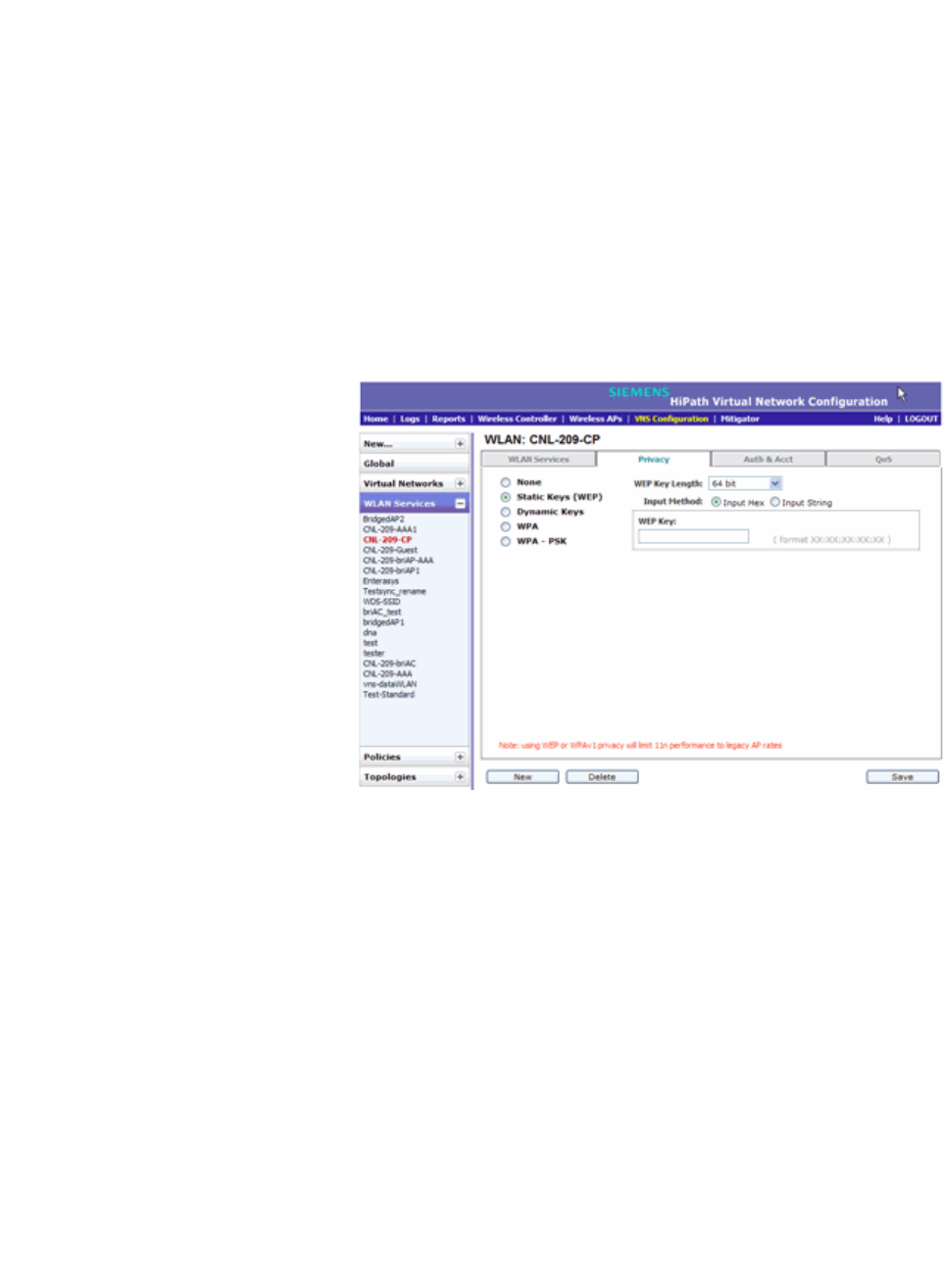
hwc_vnsconfiguration.fm
Configuring a VNS
Configuring WLAN Services
9034530-02, March 2010
HiPath Wireless Controller, Access Points and Convergence Software V7.11, User Guide 317
6.9.2.4 Configuring WLAN Service privacy
To configure privacy:
1. If the WLAN Service configuration page is not already displayed, from the
main menu, click either Wireless Controller Configuration or Virtual
Network Configuration. Then, in the left pane, select WLAN Services. The
WLAN Services window displays.
2. Select the desired service to edit from the left pane. The WLAN Service
configuration page is displayed.
3. Click the Privacy tab, then select the desired privacy method.
4. If you select Static Keys (WEP), do the following:
a) From the WEP Key Length drop-down list, click the WEP encryption key
length:
•64-bit
•128-bit
•152-bit
b) Select one of the following input methods:
• Input Hex – If you select Input Hex, type the WEP key input in the
WEP Key box. The key is generated automatically, based on the
input.
• Input String – If you select Input String, type the secret WEP key
string used for encrypting and decrypting in the Strings box. The
WEP Key box is automatically filled by the corresponding Hex code.
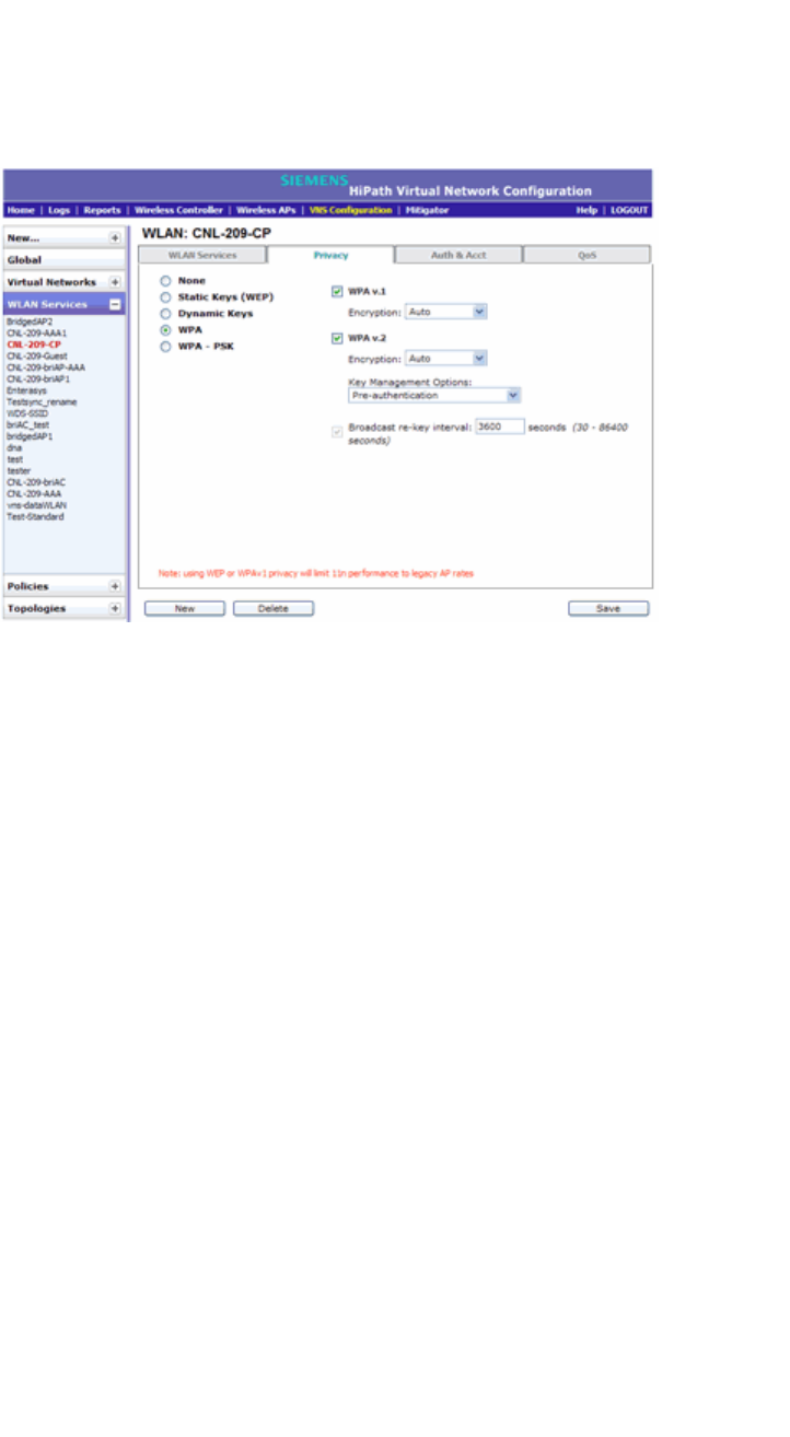
Configuring a VNS
hwc_vnsconfiguration.fm
Configuring WLAN Services
9034530-02, March 2010
318 HiPath Wireless Controller, Access Points and Convergence Software V7.11, User Guide
c) To save your changes, click Save.
5. If you select Dynamic Keys, click Save to save your changes.
6. If you select WPA, do the following:
a) To enable WPA v1 encryption, select WPA v.1. Then, click one of the
following encryption types from the Encryption drop-down list:
•Auto – The AP will advertise both TKIP and CCMP (Counter Mode
with Cipher Block Chaining Message Authentication Code Protocol)
for WPAv1. CCMP is an IEEE 802.11i encryption protocol that uses
the encryption cipher AES (Advanced Encryption Standard). Auto is
the default.
• TKIP only – The AP will advertise TKIP as an available encryption
protocol for WPAv1. It will not advertise CCMP.
b) To enable WPA v2-type encryption, select WPA v.2. Then, click one of the
following encryption types from the Encryption drop-down list:
•Auto – If you click Auto, the Wireless AP advertises both TKIP and
CCMP (counter mode with cipher block chaining message
authentication code protocol). CCMP is an IEEE 802.11i encryption
protocol that uses the encryption cipher AES (Advanced Encryption
Standard). Auto is the default.
• AES only – If you click AES, the Wireless AP advertises CCMP as an
available encryption protocol. It will not advertise TKIP.
•available encryption protocol. It will not advertise TKIP.
c) From the Key Management Options, click one of the following key
management options:
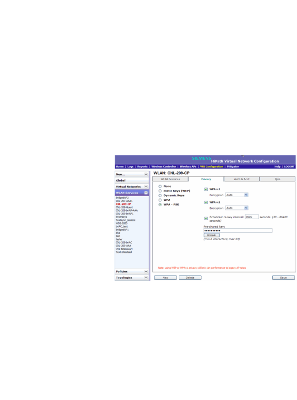
hwc_vnsconfiguration.fm
Configuring a VNS
Configuring WLAN Services
9034530-02, March 2010
HiPath Wireless Controller, Access Points and Convergence Software V7.11, User Guide 319
• None – The mobile units (client devices) performs a complete 802.1X
authentication each time it associates or connects to a Wireless AP.
• Opportunistic Keying – Enables secure fast roaming (SFR) of
mobile units. For more information, see Opportunistic Keying on page
316.
• Pre-authentication – Enables seamless roaming. For more
information, see Pre-authentication on page 316.
• Opportunistic Keying & Pre-auth – For more information, see
Opportunistic Keying & Pre-auth on page 316.
d) To change the Broadcast re-key interval, type the time interval after
which the broadcast encryption key is changed automatically. The default
is 3600 seconds.
e) Click Save to save your changes.
7. If you select WPA-PSK, do the following:
a) To enable WPA v1 encryption, select WPA v.1. Then, click one of the
following encryption types from the Encryption drop-down list:
•Auto – The AP will advertise both TKIP and CCMP (Counter Mode
with Cipher Block Chaining Message Authentication Code Protocol)
for WPAv1. CCMP is an IEEE 802.11i encryption protocol that uses
the encryption cipher AES (Advanced Encryption Standard). Auto is
the default.
• TKIP only – The AP will advertise TKIP as an available encryption
protocol for WPAv1. It will not advertise CCMP.

Configuring a VNS
hwc_vnsconfiguration.fm
Configuring WLAN Services
9034530-02, March 2010
320 HiPath Wireless Controller, Access Points and Convergence Software V7.11, User Guide
b) To enable WPA v2-type encryption, select WPA v.2. Then, click one of the
following encryption types from the Encryption drop-down list:
•Auto – If you click Auto, the Wireless AP advertises both TKIP and
CCMP (counter mode with cipher block chaining message
authentication code protocol). CCMP is an IEEE 802.11i encryption
protocol that uses the encryption cipher AES (Advanced Encryption
Standard). Auto is the default.
• AES only – If you click AES, the Wireless AP advertises CCMP as an
available encryption protocol. It will not advertise TKIP.
c) To enable re-keying after a time interval, select the Broadcast re-key
interval box, then type the time interval after which the broadcast
encryption key is changed automatically. The default is 3600 seconds.
If this checkbox is not selected, the Broadcast encryption key is never
changed and the Wireless AP will always use the same broadcast key for
Broadcast/Multicast transmissions. which will reduce the level of security
for wireless communications.
d) In the Pre-Shared Key box, type the shared secret key to be used
between the wireless device and Wireless AP. The shared secret key is
used to generate the 256-bit key.
e) To proofread your entry before saving the configuration, click Unmask to
display the Pre-Shared Key. To mask the key, click Mask.
f) To save your changes, click Save.
6.9.3 Configuring accounting and authentication
The next step in configuring a WLAN Service is to set up the authentication
mechanism. There are various authentication modes available:
•none
•Captive Portal using internal Captive Portal
•Captive Portal using external Captive Portal
•MAC-based authentication
•802.1x authentication, the wireless device user must be authenticated before
gaining network access
The first step for any type of authentication is to select RADIUS servers for:
•Authentication
•Accounting
•MAC-based authentication

hwc_vnsconfiguration.fm
Configuring a VNS
Configuring WLAN Services
9034530-02, March 2010
HiPath Wireless Controller, Access Points and Convergence Software V7.11, User Guide 321
6.9.3.1 Vendor Specific Attributes
In addition to the standard RADIUS message, you can include Vendor Specific
Attributes (VSAs). The Controller, Access Points and Convergence Software
authentication mechanism provides six VSAs for RADIUS and other
authentication mechanisms.
The first five of these VSAs provide information on the identity of the specific
Wireless AP that is handling the wireless device, enabling the provision of
location-based services.
The RADIUS message also includes RADIUS attributes Called-Station-Id and
Calling-Station-Id in order to include the MAC address of the wireless device.
Note: Siemens-URL-Redirection is supported by MAC-based authentication.
6.9.3.2 Defining accounting methods for a WLAN Service
Accounting tracks the activity of wireless device users. There are two types of
accounting available:
Attribute Name ID Type Messages Description
Siemens-URL-
Redirection
1 string Returned from
RADIUS server
A URL that can be returned to
redirect a session to a specific Web
page.
Siemens-AP-
Name
2 string Sent to
RADIUS server
The name of the AP the client is
associating to. It can be used to
assign policy based on AP name or
location.
Siemens-AP-
Serial
3 string Sent to
RADIUS server
The AP serial number. It can be
used instead of (or in addition to)
the AP name.
Siemens-VNS-
Name
4 string Sent to
RADIUS server
The name of the Virtual Network
the client has been assigned to. It is
used in assigning policy and billing
options, based on service selection.
Siemens-SSID 5 string Sent to
RADIUS server
The name of the SSID the client is
associating to. It is used in
assigning policy and billing options,
based on service selection.
Siemens-BSS-
MAC
6 string Sent to
RADIUS server
The name of the BSS-ID the client
is associating to. It is used in
assigning policy and billing options,
based on service selection and
location.
Table 22 Vendor Specific Attributes
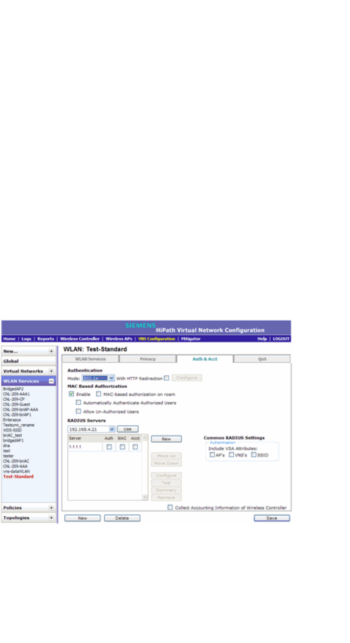
Configuring a VNS
hwc_vnsconfiguration.fm
Configuring WLAN Services
9034530-02, March 2010
322 HiPath Wireless Controller, Access Points and Convergence Software V7.11, User Guide
• HiPath Wireless Controller accounting – Enables the HiPath Wireless
Controller to generate Call Data Records (CDRs), containing usage
information about each wireless session. CDR generation is enabled on a per
VNS basis. For more information on CDRs, refer to section Section 11.3, “Call
Detail Records (CDRs)”, on page 443.
• RADIUS accounting – Enables the HiPath Wireless Controller to generate
an accounting request packet with an accounting start record after successful
login by the wireless device user, and an accounting stop record based on
session termination. The HiPath Wireless Controller sends the accounting
requests to a remote RADIUS server.
HiPath Wireless Controller accounting creates Call Data Records (CDRs). If
RADIUS accounting is enabled, a RADIUS accounting server needs to be
specified.
To define accounting methods:
1. From the main menu, click Virtual Network Configuration. The Virtual
Network Configuration screen is displayed.
2. In the left pane expand the WLAN Services pane, then click the WLAN
Service you want to define accounting methods for. The WLAN Services
configuration page is displayed.
3. Click the Auth & Acct tab.
4. To enable HiPath Wireless Controller accounting, select Collect Accounting
Information of Wireless Controller.
5. To enable RADIUS accounting, from the RADIUS Servers drop-down list,
click the RADIUS server you want to use for RADIUS accounting, and then
click Use.
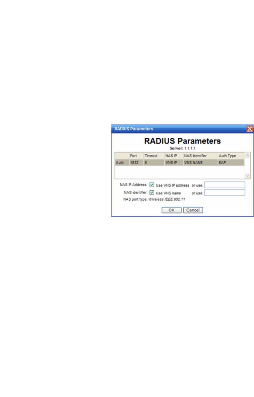
hwc_vnsconfiguration.fm
Configuring a VNS
Configuring WLAN Services
9034530-02, March 2010
HiPath Wireless Controller, Access Points and Convergence Software V7.11, User Guide 323
The server name is added to the Server table of assigned RADIUS servers.
The selected server is no longer available in the RADIUS servers drop-down
list.
The RADIUS servers are defined on the Global Settings screen. For more
information, see Section 6.2.1, “Defining RADIUS servers and MAC address
format”, on page 247.
6. In the Server table, select the checkbox in the Acct column to enable
accounting for each applicable RADIUS server.
7. In the Server table click the RADIUS server, and then click Configure.The
RADIUS Parameters dialog is displayed.
The configured values for the selected server are displayed in the table at the
top.
8. For NAS IP Address, accept the default of “Use VNS IP address” or de-select
the checkbox and type the IP address of a Network Access Server (NAS).
9. For NAS Identifier, accept the default of “Use VNS name” or type the
Network Access Server (NAS) identifier. The NAS identifier is a RADIUS
attribute that identifies the server responsible for passing information to
designated RADIUS servers and then acting on the response returned.
10. Click OK.
11. To save your changes, click Save.
6.9.3.3 Configuring authentication for a WLAN Service
802.1x Authentication
If 802.1x authentication mode is configured, the wireless device must
successfully complete the user authentication verification prior to being granted
network access. This enforcement is performed by both the user's client and the

Configuring a VNS
hwc_vnsconfiguration.fm
Configuring WLAN Services
9034530-02, March 2010
324 HiPath Wireless Controller, Access Points and Convergence Software V7.11, User Guide
AP. The wireless device's client utility must support 802.1x. The user's EAP
packets request for network access along with login identification or a user profile
is forwarded by the HiPath Wireless Controller to a RADIUS server.
Captive Portal authentication
For Captive Portal authentication, the wireless device connects to the network,
but can only access the specific network destinations defined in the non-
authenticated filter. For more information, see Section 6.10.2, “About filtering
rules”, on page 352. One of these destinations should be a server, either internal
or external, which presents a Web login page — the Captive Portal. The wireless
device user must input an ID and a password. This request for authentication is
sent by the HiPath Wireless Controller to a RADIUS server or other authentication
server. Based on the permissions returned from the authentication server, the
HiPath Wireless Controller implements policy and allows the appropriate network
access.
Captive Portal authentication relies on a RADIUS server on the enterprise
network. There are three mechanisms by which Captive Portal authentication can
be carried out:
• Internal Captive Portal – The HiPath Wireless Controller displays the
Captive Portal Web page, carries out the authentication, and implements
policy.
• External Captive Portal – After an external server displays the Captive
Portal Web page and carries out the authentication, the HiPath Wireless
Controller implements policy.
• External Captive Portal with internal authentication – After an external
server displays the Captive Portal Web page, the HiPath Wireless Controller
carries out the authentication and implements policy.
RADIUS servers
RADIUS servers can perform the following for a WLAN Service:
• Authentication – RADIUS servers are configured to provide authentication.
• MAC authentication – RADIUS servers are configured to provide MAC-
based authentication.
• Accounting – RADIUS servers are configured to provide accounting
services.
MAC-based authentication
MAC-based authentication enables network access to be restricted to specific
devices by MAC address. The HiPath Wireless Controller queries a RADIUS
server for a MAC address when a wireless client attempts to connect to the
network.
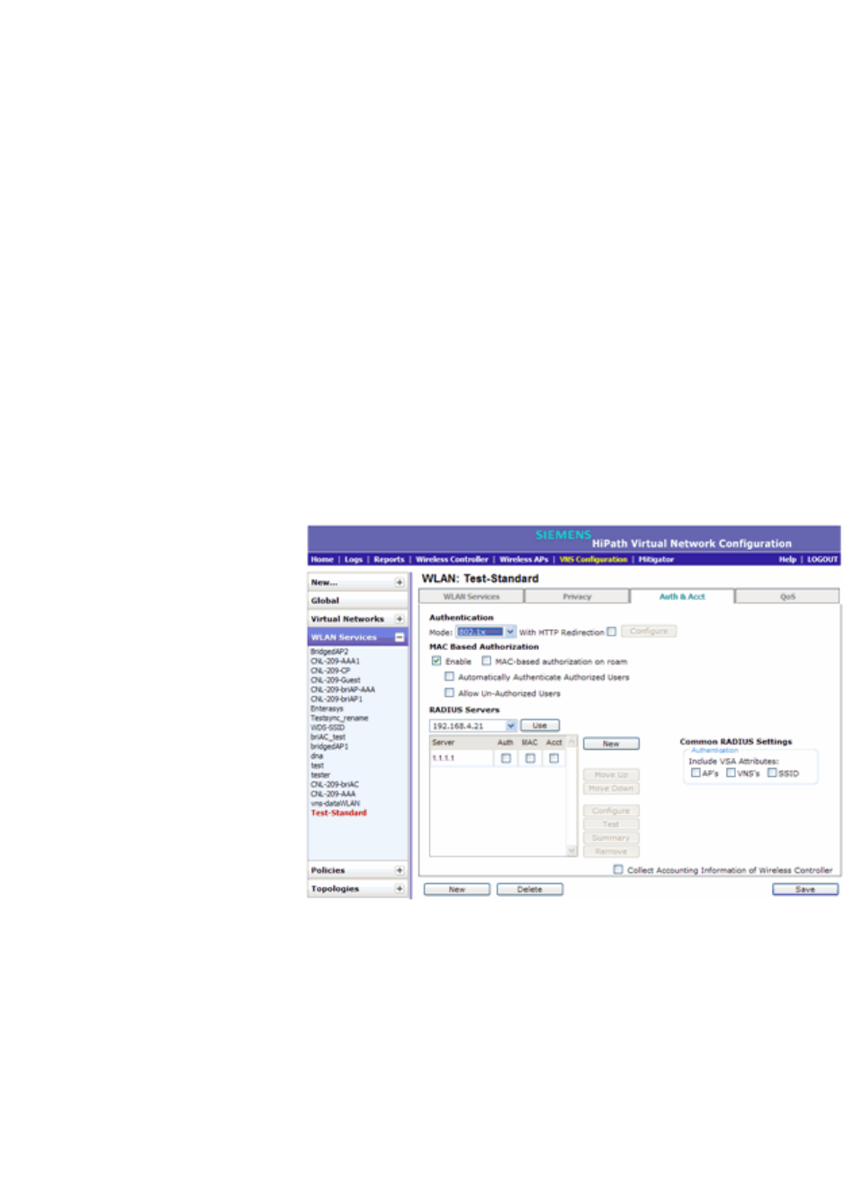
hwc_vnsconfiguration.fm
Configuring a VNS
Configuring WLAN Services
9034530-02, March 2010
HiPath Wireless Controller, Access Points and Convergence Software V7.11, User Guide 325
MAC-based authentication can be set up on any type of WLAN Service. To set
up a RADIUS server for MAC-based authentication, you must set up a user
account with UserID=MAC and Password=MAC (or a password defined by the
administrator) for each user. Specifying a MAC address format and policy
depends on which RADIUS server is being used.
If MAC-based authentication is to be used in conjunction with the 802.1x or
Captive Portal authentication, an additional account with a real UserID and
Password must also be set up on the RADIUS server.
MAC-based authentication responses may indicate to the HiPath Wireless
Controller what VNS a user should be assigned to. Authentication (if enabled) can
apply on every roam.
To assign RADIUS servers for authentication:
1. From the main menu, click Virtual Network Configuration. The Virtual
Network Configuration screen is displayed.
2. In the left pane expand the WLAN Services pane, then click the WLAN
Service. The WLAN Services configuration page is displayed.
3. Click the Auth & Acct tab.
4. If applicable, in the MAC Based Authorization section, select the Enable
checkbox to enable the RADIUS server to perform MAC-based
authentication for the VNS with Captive Portal.

Configuring a VNS
hwc_vnsconfiguration.fm
Configuring WLAN Services
9034530-02, March 2010
326 HiPath Wireless Controller, Access Points and Convergence Software V7.11, User Guide
MAC-based authorization on roam – If MAC-based authentication is
enabled, select the MAC-based authorization on roam checkbox.
Note: Only select this checkbox if you want your clients to be authorized
every time they roam to another Wireless AP. If this option is not enabled, and
MAC-based authentication is in use, the client is authenticated only at the
start of a session.
5. In the RADIUS Servers drop-down list, click the server you want to assign to
the WLAN Service, and then click Use.
The server name is added to the Server table of assigned RADIUS servers.
The selected server is no longer available in the RADIUS servers drop-down
list.
The RADIUS servers are defined on the Global Settings screen. For more
information, see Section 6.2.1, “Defining RADIUS servers and MAC address
format”, on page 247.
6. In the Server table, select the checkboxes in the Auth, MAC, or Acct
columns, to enable the authentication or accounting, if applicable.
7. To save your changes, click Save.
6.9.3.4 Defining the RADIUS server priority for RADIUS
redundancy
If more than one server has been defined for any type of authentication, you can
define the priority of the servers in the case of failover.
In the event of a failover of the main RADIUS server—if there is no response after
the set number of retries—then the other servers in the list will be polled on a
round-robin basis until a server responds.
If all defined RADIUS servers fail to respond, a critical message is generated in
the logs.
To define the RADIUS server priority for RADIUS redundancy:
1. From the main menu, click Virtual Network Configuration. The Virtual
Network Configuration screen is displayed.
2. In the left pane expand the WLAN Services pane, then click the WLAN
Service. The WLAN Services configuration page is displayed.
3. Click the Auth & Acct tab.
4. In the Server table, click the RADIUS server and then click Move Up or Move
Down to arrange the order. The first server in the list is the active one.
5. To save your changes, click Save.

hwc_vnsconfiguration.fm
Configuring a VNS
Configuring WLAN Services
9034530-02, March 2010
HiPath Wireless Controller, Access Points and Convergence Software V7.11, User Guide 327
6.9.3.5 Configuring assigned RADIUS servers
Configuring assigned RADIUS servers for a VNS can include the following:
•Defining common RADIUS settings
•Defining RADIUS settings for individual RADIUS servers
•Testing RADIUS server connections
•Viewing the RADIUS server configuration summary
•Removing assigned RADIUS servers
To define common RADIUS settings:
1. From the main menu, click Virtual Network Configuration. The Virtual
Network Configuration screen is displayed.
2. In the left pane expand the WLAN Services pane, then click the WLAN
Service. The WLAN Services configuration page is displayed.
3. Click the Auth & Acct tab.
4. In the Common RADIUS Settings section, select the appropriate
checkboxes to include the Vendor Specific Attributes in the message to the
RADIUS server:
•AP’s
•VNS’s
• SSID
The Vendor Specific Attributes must be defined on the RADIUS server.
5. To save your changes, click Save.
To define RADIUS settings for individual RADIUS servers:
1. From the main menu, click Virtual Network Configuration. The Virtual
Network Configuration screen is displayed.
2. In the left pane expand the WLAN Services pane, then click the WLAN
Service. The WLAN Services configuration page is displayed.
3. Click the Auth & Acct tab.
4. In the Server table, click the RADIUS server you want to define, and then
click Configure. The RADIUS Parameters dialog is displayed.
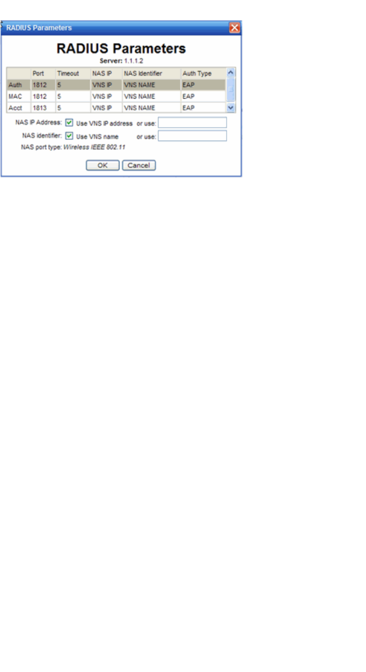
Configuring a VNS
hwc_vnsconfiguration.fm
Configuring WLAN Services
9034530-02, March 2010
328 HiPath Wireless Controller, Access Points and Convergence Software V7.11, User Guide
5. For NAS IP Address, accept the default of “Use VNS IP address” or de-select
the checkbox and type the IP address of a Network Access Server (NAS).
6. For NAS Identifier, accept the default of “Use VNS name” or type the
Network Access Server (NAS) identifier. The NAS identifier is a RADIUS
attribute that identifies the server responsible for passing information to
designated RADIUS servers and then acting on the response returned.
7. Click OK.
8. To save your changes, click Save.
To test RADIUS server connections:
1. From the main menu, click Virtual Network Configuration. The Virtual
Network Configuration screen is displayed.
2. In the left pane expand the WLAN Services pane, then click the WLAN
Servicer. The WLAN Services configuration page is displayed.
3. Click the Auth & Acct tab.
4. In the Server table, click the RADIUS server whose connection you want to
test, and then click Test. The Test RADIUS Servers screen is displayed.
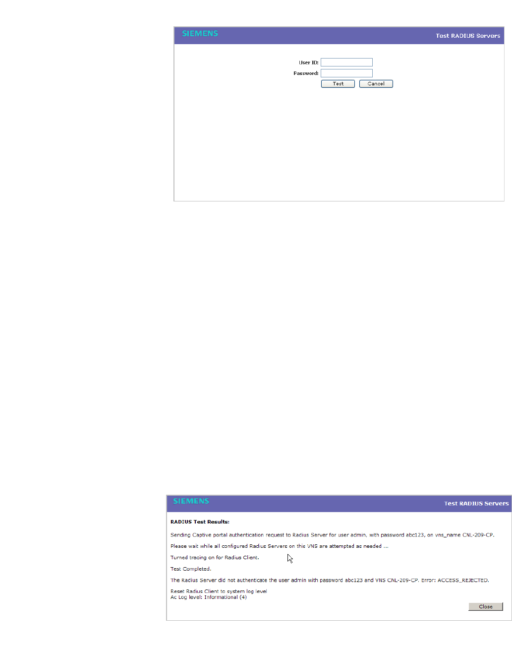
hwc_vnsconfiguration.fm
Configuring a VNS
Configuring WLAN Services
9034530-02, March 2010
HiPath Wireless Controller, Access Points and Convergence Software V7.11, User Guide 329
The RADIUS test is a test of connectivity to the RADIUS server, not of full
RADIUS functionality. The HiPath Wireless Controller’s RADIUS connectivity
test initiates an Access-Request, to which the RADIUS server will respond. If
a response is received (either Access-Reject or Access-Accept), then the test
is deemed to have succeeded. If a response is not received, then the test is
deemed to have failed. In either case, the test ends at this point.
If the WLAN Service Authentication mode is Internal or External Captive
Portal, or if MAC-Based Authorization is selected, then this test can also test
a user account configured on the RADIUS server. In these cases, if proper
credentials are filled in for User ID and Password, an Access-Accept could
be returned.
If the WLAN Service Authentication mode is 802.1x, however, an Access-
Reject is expected if the RADIUS server is accessible, and the text is
considered a success.
5. In the User ID box, type the user ID that you know can be authenticated.
6. In the Password box, type the corresponding password. A password is not
required for a AAA VNS.
7. Click Test. The Test Result screen is displayed.
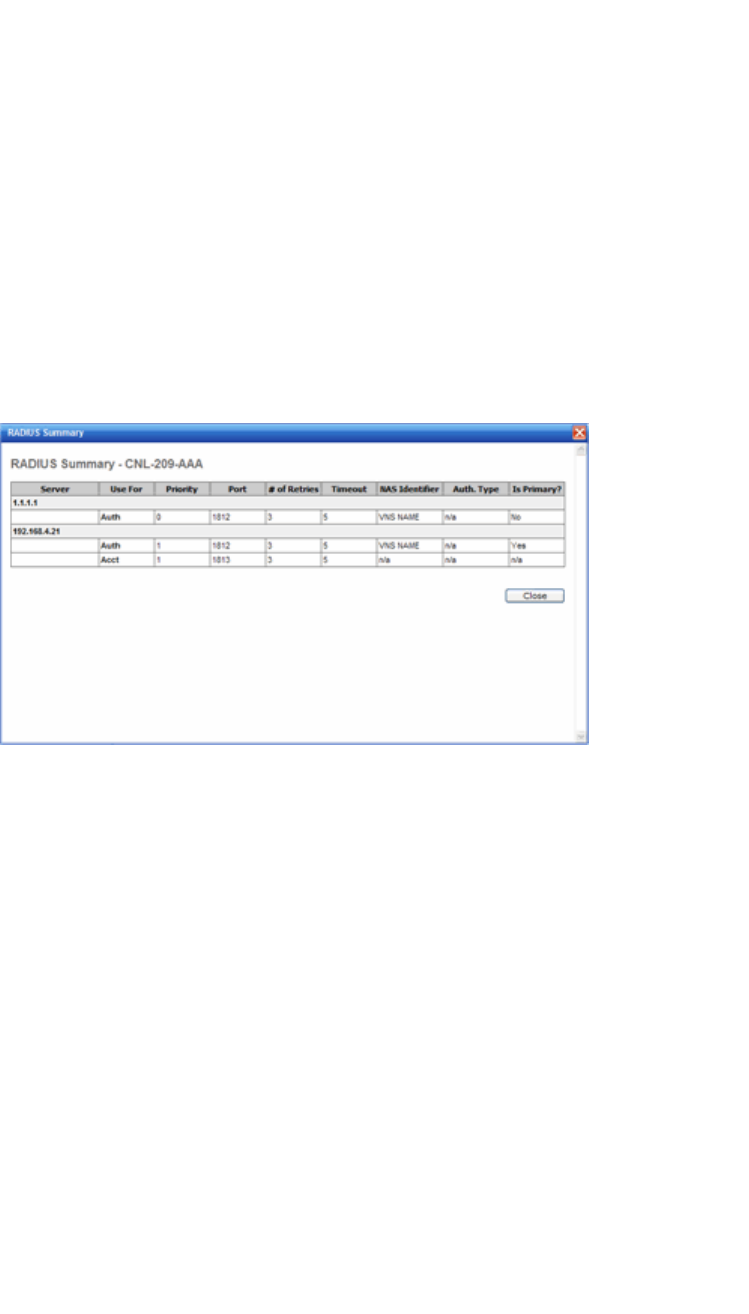
Configuring a VNS
hwc_vnsconfiguration.fm
Configuring WLAN Services
9034530-02, March 2010
330 HiPath Wireless Controller, Access Points and Convergence Software V7.11, User Guide
8. Click Close.
9. To save your changes, click Save.
To view the RADIUS server configuration summary:
1. From the main menu, click Virtual Network Configuration. The Virtual
Network Configuration screen is displayed.
2. In the left pane expand the WLAN Services pane, then click the WLAN
Servicer. The WLAN Services configuration page is displayed.
3. Click the Auth & Acct tab.
4. In the Server table, click a RADIUS server whose configuration summary you
want to view, and then click Summary. The RADIUS Summary screen is
displayed.
5. Click Close.
6. To save your changes, click Save.
To remove an assigned RADIUS server from a WLAN Service:
1. From the main menu, click Virtual Network Configuration. The Virtual
Network Configuration screen is displayed.
2. In the left pane expand the WLAN Services pane, then click the WLAN
Service you want to define accounting methods for. The WLAN Services
configuration page is displayed.
3. Click the Auth & Acct tab.
4. In the Server table, click the assigned RADIUS server that you want to
remove from the VNS, and then click Remove. The RADIUS server is
removed from the VNS.
5. To save your changes, click Save.

hwc_vnsconfiguration.fm
Configuring a VNS
Configuring WLAN Services
9034530-02, March 2010
HiPath Wireless Controller, Access Points and Convergence Software V7.11, User Guide 331
6.9.3.6 Defining a WLAN Service with no authentication
You can set up a WLAN Service that will bypass all authentication mechanisms
and run the HiPath Wireless Controller, Access Points and Convergence
Software with no authentication of a wireless device user.
A WLAN Service with no authentication can still control network access using
filtering rules. For more information on how to set up filtering rules that allow
access only to specified IP addresses and ports, see Section 6.10.2, “About
filtering rules”, on page 352.
To define a WLAN Service with no authentication:
1. From the main menu, click Virtual Network Configuration. The Virtual
Network Configuration screen is displayed.
2. In the left pane expand the WLAN Services pane, then click the WLAN
Service you want to configure or click New. The WLAN Services
configuration page is displayed.
3. Configure the service as described in Section 6.9, “Configuring WLAN
Services”, on page 308.
4. Click the Auth & Acct tab.
5. From the Authentication Mode drop-down list, select Disabled.
6. To save your changes, click Save.
6.9.3.7 Configuring Captive Portal for internal or external
authentication
There are four Captive Portal options:
• Internal Captive Portal – Define the parameters of the internal Captive
Portal page displayed by the HiPath Wireless Controller, and the
authentication request from the HiPath Wireless Controller to the RADIUS
server.
• External Captive Portal – Define the parameters of the external Captive
Portal page displayed by an external server. The authentication can be
carried out by an external authentication server or by the HiPath Wireless
Controller request to a RADIUS server.
• GuestPortal – Define the parameters for a GuestPortal Captive Portal page.
A GuestPortal provides wireless device users with temporary guest network
services.
• Guest Splash – Define the parameters of the Guest Splash page displayed
by the HiPath Wireless Controller. These parameters are similar to those for
an internal Captive Portal page, except that the options to configure the labels
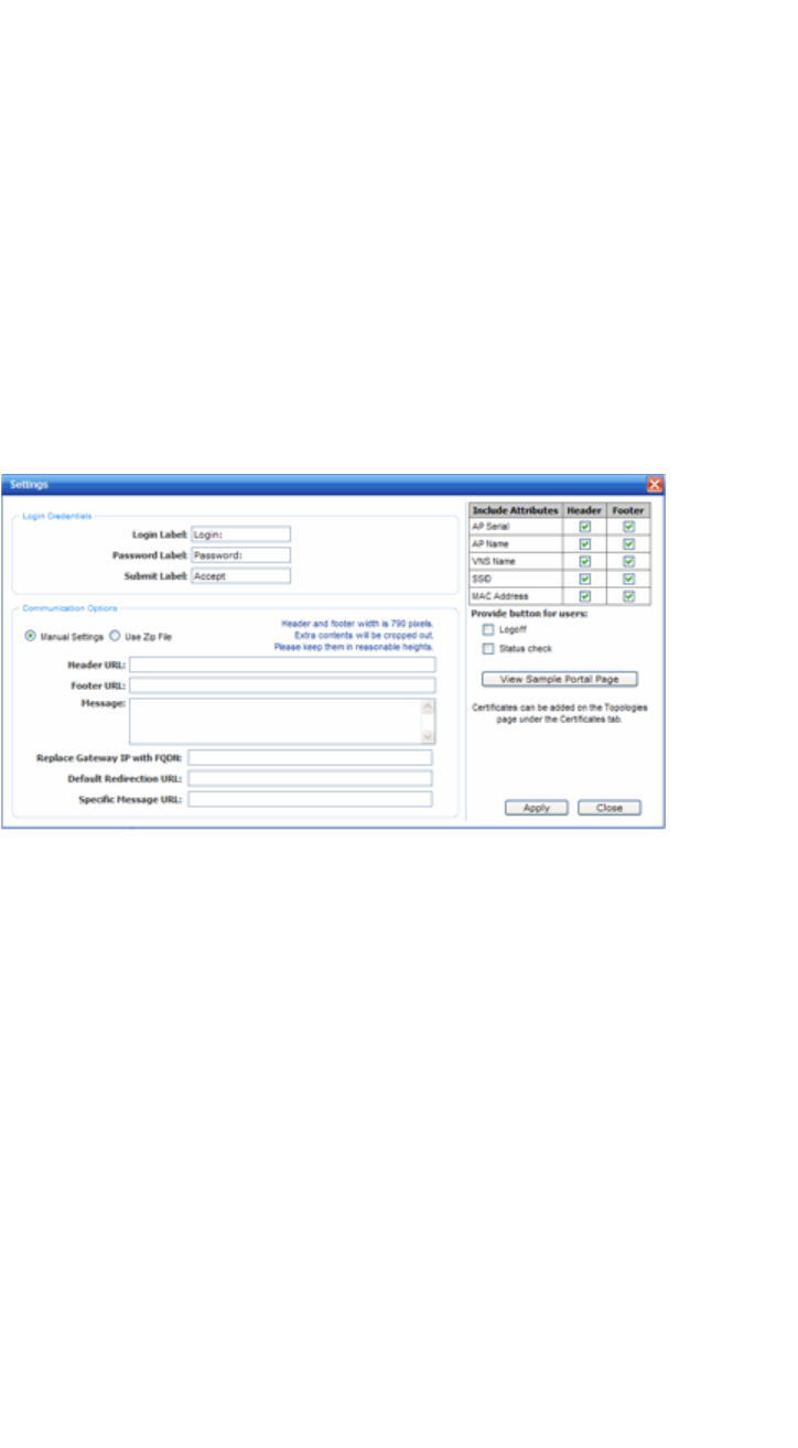
Configuring a VNS
hwc_vnsconfiguration.fm
Configuring WLAN Services
9034530-02, March 2010
332 HiPath Wireless Controller, Access Points and Convergence Software V7.11, User Guide
for user id and password fields are not present since login information is not
required when the user is re-directed to the authorization Web page. This
type of Captive Portal could be used where the user is expected to read and
accept some terms and conditions before being granted network access.
To configure the Captive Portal settings for internal Captive Portal:
1. From the main menu, click Virtual Network Configuration. The Virtual
Network Configuration screen is displayed.
2. In the left pane expand the WLAN Services pane, then click the WLAN
Service. The WLAN Services configuration page is displayed.
3. Click the Auth & Acct tab.
4. In the Authentication Mode drop-down list, click Internal, and then click
Configure. The Captive Portal Settings screen is displayed.
5. In the Login Credentials section, do the following:
•In the Login Label box, type the text that will be displayed as a label for
the user login field.
•In the Password Label box, type the text that will be displayed as a label
for the user password field.
•In the Submit Label box, type the text that will be displayed as a label for
the submit button.
6. In the Communication Options section, do one of the following:
• Manual Settings – Select this option if you want to manually define the
location of the files that will be used for the header and footer of the
Captive Portal page.

hwc_vnsconfiguration.fm
Configuring a VNS
Configuring WLAN Services
9034530-02, March 2010
HiPath Wireless Controller, Access Points and Convergence Software V7.11, User Guide 333
a) In the Header URL box, type the server location of the file to be
displayed in the Header portion of the Captive Portal page. This page
can be customized to suit your organization, with logos or other
graphics.
Caution: If you use logos or graphics, ensure that the graphics or logos are
appropriately sized. Large graphics or logos may force the login section out
of view.
b) In the Footer URL box, type the server location of the file to be
displayed in the Footer portion of the Captive Portal page.
c) In the Message box, type the message that will be displayed above
the Login box to greet the user. For example, the message could
explain why the Captive Portal page is appearing, and instructions for
the user. The message can be a maximum of 255 characters,
including spaces.
• Use Zip File – Select this option to upload a zip file that contains custom
Captive Portal content.
The zip file you upload must have a flat structure — it cannot contain any
sub-directories. The contents of the zip must adhere to the following file
formats:
•Content to be used in the Captive Portal header must be in a file
named portalheader.htm.
•Content to be used in the Captive Portal footer must be in a file named
portalfooter.htm.
•The number of graphics and the size of the graphics is unlimited, and
can be either .gif, .jpg, or .png.
Note: The html files must only contain html. JavaScript, redirects, or
dynamic CS is not permitted.
7. In the Replace Gateway IP with FQDN box, type the appropriate name if a
Fully Qualified Domain Name (FQDN) is used as the gateway address.
8. In the Default Redirection URL box, type the URL to which the wireless
device user will be directed to after authentication.
9. In the Specific Message URL box, type the URL of a document that will be
displayed in a text frame on the Captive Portal login page. This text frame can
be used to display lengthier messages, such as terms and conditions of use
for users who have not yet logged in.

Configuring a VNS
hwc_vnsconfiguration.fm
Configuring WLAN Services
9034530-02, March 2010
334 HiPath Wireless Controller, Access Points and Convergence Software V7.11, User Guide
10. In the right pane, select the appropriate checkboxes in both Header and
Footer columns, if applicable, to include the following VSA Attributes in the
message to the authentication server:
•AP Serial
•AP Name
•VNS Name
•SSID
•MAC Address
The selections influence what URL is returned in either section. For example,
wireless users can be identified by which Wireless AP or which VNS they are
associated with, and can be presented with a Captive Portal Web page that
is customized for those identifiers.
11. To provide users with a logoff button, select Logoff. The Logoff button
launches a pop-up logoff page, allowing users to control their logoff.
When the user clicks the Logoff button, the user is disassociated and returns
to the non-authenticated state.
12. To provide users with a status check button, select Status check. The Status
check button launches a pop-up window, which allows users to monitor
session statistics such as system usage and time left in a session.
13. To install a certificate for the internal Captive Portal page, refer to Section
3.4.8, “Installing certificates on the HiPath Wireless Controller”, on page 71.
14. Click Apply.
15. To see how the Captive Portal page you have designed will look, click View
Sample Portal Page.
Caution: In order for Captive Portal authentication to be successful, all the
URLs referenced in the Captive Portal setup must also be specifically
identified and allowed in the non-authenticated filter. For more information,
see Section 6.10.2, “About filtering rules”, on page 352.
16. To save your changes, click Save.
To configure the Captive Portal Settings for external Captive Portal:
1. From the main menu, click Virtual Network Configuration. The Virtual
Network Configuration screen is displayed.
2. In the left pane expand the WLAN Services pane, then click the WLAN
Service. The WLAN Services configuration page is displayed.
3. Click the Auth & Acct tab.
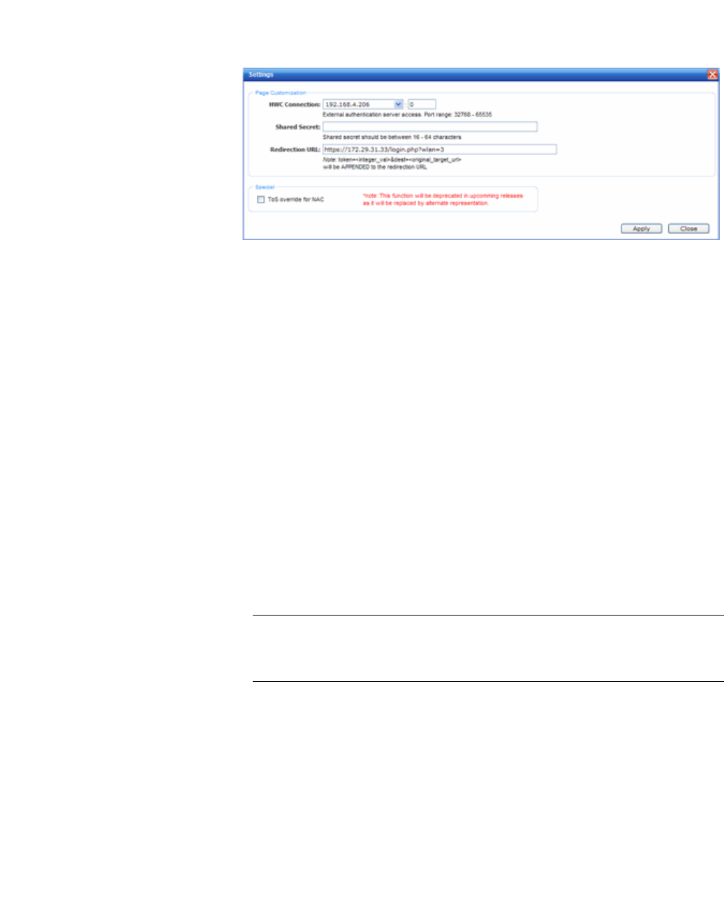
hwc_vnsconfiguration.fm
Configuring a VNS
Configuring WLAN Services
9034530-02, March 2010
HiPath Wireless Controller, Access Points and Convergence Software V7.11, User Guide 335
4. In the Authentication Mode drop-down list, click External, and then click
Configure. The Captive Portal Settings screen is displayed.
5. In the HWC Connection drop-down list, click the IP address of the external
Web server.
6. Type the port of the HiPath Wireless Controller.
If there is an authentication server configured for this VNS, the external
Captive Portal page on the external authentication server will send the
request back to the HiPath Wireless Controller to allow the HiPath Wireless
Controller to continue with the RADIUS authentication and filtering.
7. In the Shared Secret box, type the password common to both the HiPath
Wireless Controller and the external Web server if you want to encrypt the
information passed between the HiPath Wireless Controller and the external
Web server.
8. In the Redirection URL box, type the URL to which the wireless device user
will be directed to after authentication.
9. Click Apply.
10. To save your changes, click Save.
Note: You must add a filtering rule to the non-authenticated filter that allows
access to the external Captive Portal site. For more information, see Section
6.10.2, “About filtering rules”, on page 352.
To configure the Captive Portal settings for a GuestPortal:
1. From the main menu, click Virtual Network Configuration. The Virtual
Network Configuration screen is displayed.
2. In the left pane expand the WLAN Services pane, then click the WLAN
Service. The WLAN Services configuration page is displayed.
3. Click the Auth & Acct tab.
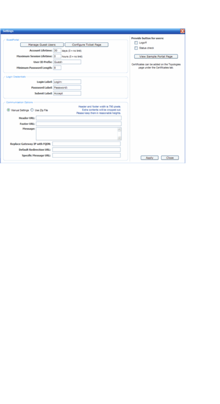
Configuring a VNS
hwc_vnsconfiguration.fm
Configuring WLAN Services
9034530-02, March 2010
336 HiPath Wireless Controller, Access Points and Convergence Software V7.11, User Guide
4. In the Authenticationi Mode drop-down list, click GuestPortal, and then
click Configure. The Captive Portal Settings screen is displayed.
5. In the GuestPortal section, do the following:
•To add and configure guest user accounts, click Manage Guest Users.
For more information, see Section 12.2.1, “Working with GuestPortal
Guest administration”, on page 455.
•To configure the GuestPortal ticket, click Configure Ticket Page. For
more information, see Section 12.2.1.7, “Working with the GuestPortal
ticket page”, on page 466.
•In the Account lifetime box, type the account lifetime, in days, for the
guest account. A value of 0 specifies no limit to the account lifetime.
•In the Maximum Session Lifetime box, type the maximum session
lifetime, in hours, for the guest account. The default 0 value does not limit
a session lifetime. The session lifetime is the allowed cumulative total in
hours spent on the network during the account lifetime.
•In the User ID Prefix, type a prefix that will be added to all guest account
user IDs. The default is Guest.
•In the Minimum Password Length, type a minimum password length
that will be applied to all guest accounts.
6. In the Login Credentials section, do the following:
•In the Login Label box, type the text that will be displayed as a label for
the user login field.

hwc_vnsconfiguration.fm
Configuring a VNS
Configuring WLAN Services
9034530-02, March 2010
HiPath Wireless Controller, Access Points and Convergence Software V7.11, User Guide 337
•In the Password Label box, type the text that will be displayed as a label
for the user password field.
•In the Submit Label box, type the text that will be displayed as a label for
the submit button.
7. In the Communication Options section, do one of the following:
• Manual Settings – Select this option if you want to manually define the
location of the files that will be used for the header and footer of the
Captive Portal page.
a) In the Header URL box, type the server location of the file to be
displayed in the Header portion of the Captive Portal page. This page
can be customized to suit your organization, with logos or other
graphics.
Caution: If you use logos or graphics, ensure that the graphics or logos are
appropriately sized. Large graphics or logos may force the login section out
of view.
b) In the Footer URL box, type the server location of the file to be
displayed in the Footer portion of the Captive Portal page.
c) In the Message box, type the message that will be displayed above
the Login box to greet the user. For example, the message could
explain why the Captive Portal page is appearing, and instructions for
the user. The message can be a maximum of 255 characters,
including spaces.
• Use Zip File – Select this option to upload a zip file that contains custom
Captive Portal content.
The zip file you upload must have a flat structure — it cannot contain any
sub-directories. The contents of the zip must adhere to the following file
formats:
•Content to be used in the Captive Portal header must be in a file
named portalheader.htm.
•Content to be used in the Captive Portal footer must be in a file named
portalfooter.htm.
•The number of graphics and the size of the graphics is unlimited, and
can be either .gif, .jpg, or .png.
Note: The html files contain must only contain html. JavaScript, redirects,
or dynamic CS is not permitted.

Configuring a VNS
hwc_vnsconfiguration.fm
Configuring WLAN Services
9034530-02, March 2010
338 HiPath Wireless Controller, Access Points and Convergence Software V7.11, User Guide
8. In the Replace Gateway IP with FQDN box, type the appropriate name if a
Fully Qualified Domain Name (FQDN) is used as the gateway address.
9. In the Default Redirection URL box, type the URL to which the wireless
device user will be directed to after authentication.
10. In the Specific Message URL box, type the URL of a document that will be
displayed in a text frame on the Captive Portal login page. This text frame can
be used to display lengthier messages, such as terms and conditions of use
for users who have not yet logged in.
11. In the right pane, select the appropriate checkboxes:
•To provide users with a logoff button, select Logoff. The Logoff button
launches a pop-up logoff page, allowing users to control their logoff.
When the user clicks the Logoff button, the user is disassociated and
returns to the non-authenticated state.
•To provide users with a status check button, select Status check. The
Status check button launches a pop-up window, which allows users to
monitor session statistics such as system usage and time left in a
session.
12. To install a certificate for the internal Captive Portal page, refer to Section
3.4.8, “Installing certificates on the HiPath Wireless Controller”, on page 71.
13. Click Apply.
14. To see how the Captive Portal page you have designed will look, click View
Sample Portal Page.
Caution: In order for Captive Portal authentication to be successful, all the
URLs referenced in the Captive Portal setup must also be specifically
identified and allowed in the non-authenticated filter. For more information,
see Section 6.10.2, “About filtering rules”, on page 352.
15. To save your changes, click Save.
To configure the Captive Portal settings for Guest Splash:
1. From the main menu, click Virtual Network Configuration. The Virtual
Network Configuration screen is displayed.
2. In the left pane expand the WLAN Services pane, then click the WLAN
Service. The WLAN Services configuration page is displayed.
3. Click the Auth & Acct tab.
4. In the Authentication Mode drop-down list, click Guest Splash, and then
click Configure. The Guest Splash Settings screen is displayed.
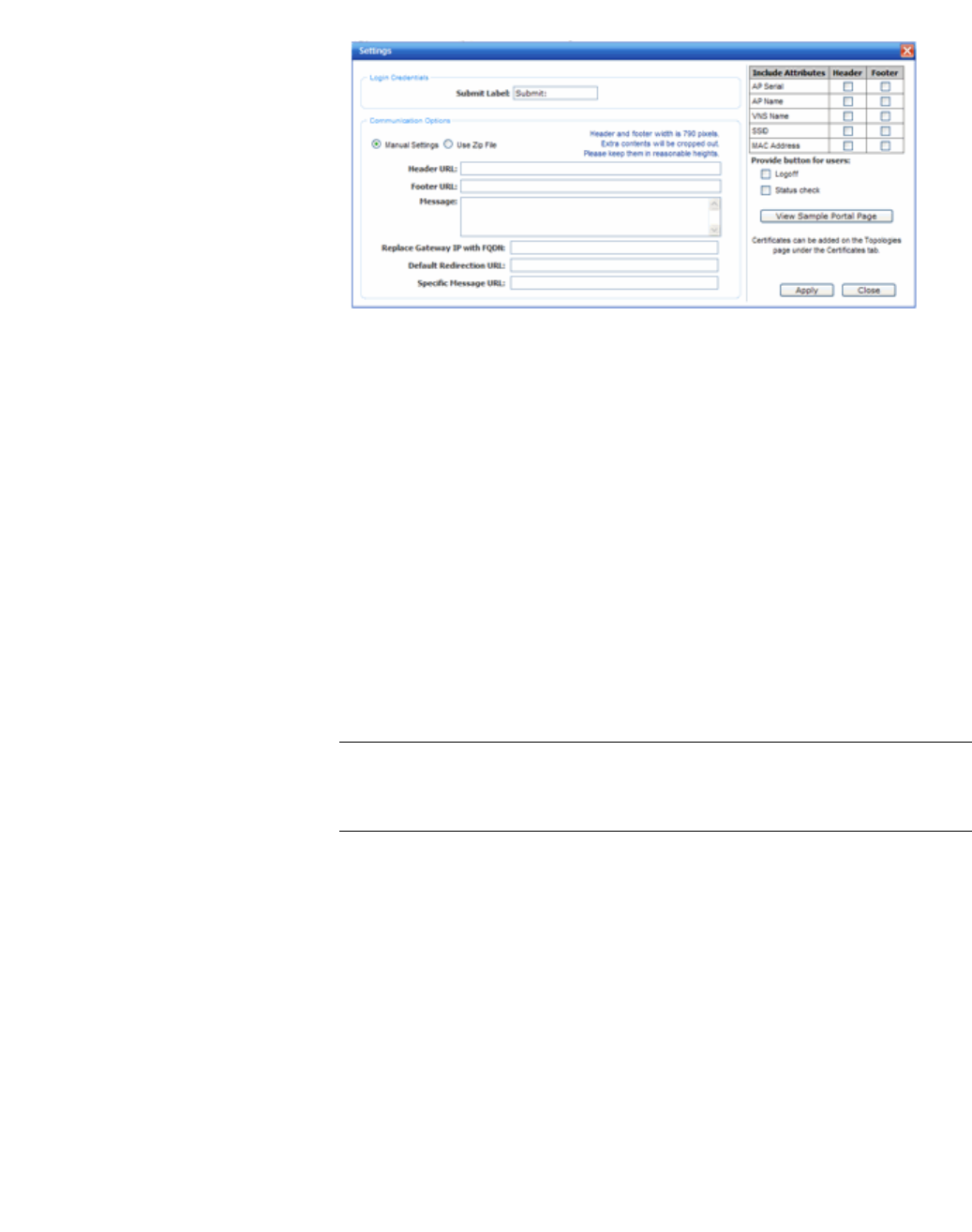
hwc_vnsconfiguration.fm
Configuring a VNS
Configuring WLAN Services
9034530-02, March 2010
HiPath Wireless Controller, Access Points and Convergence Software V7.11, User Guide 339
5. In the Login Credentials section, do the following:
•In the Submit Label box, type the text that will be displayed as a label for
the submit button. This text should be “Accept” or something similar, since
pressing the button will indicate that the user accepts the terms and
conditions.
6. In the Communication Options section, do one of the following:
• Manual Settings – Select this option if you want to manually define the
location of the files that will be used for the header and footer of the
Captive Portal page.
a) In the Header URL box, type the server location of the file to be
displayed in the Header portion of the Captive Portal page. This page
can be customized to suit your organization, with logos or other
graphics.
Caution: If you use logos or graphics, ensure that the graphics or logos are
appropriately sized. Large graphics or logos may force the login section out
of view.
b) In the Footer URL box, type the server location of the file to be
displayed in the Footer portion of the Captive Portal page.
c) In the Message box, type the message that will be displayed above
the Login box to greet the user. Use this field to make it clear that by
pressing the “Accept” button, the user accepts the terms and
conditions. The message can be a maximum of 255 characters,
including spaces.
• Use Zip File – Select this option to upload a zip file that contains custom
Captive Portal content.
The zip file you upload must have a flat structure — it cannot contain any
sub-directories. The contents of the zip must adhere to the following file
formats:

Configuring a VNS
hwc_vnsconfiguration.fm
Configuring WLAN Services
9034530-02, March 2010
340 HiPath Wireless Controller, Access Points and Convergence Software V7.11, User Guide
•Content to be used in the Captive Portal header must be in a file
named portalheader.htm.
•Content to be used in the Captive Portal footer must be in a file named
portalfooter.htm.
•The number of graphics and the size of the graphics is unlimited, and
can be either .gif, .jpg, or .png.
Note: The html files must only contain html. JavaScript, redirects, or
dynamic CS is not permitted.
7. In the Replace Gateway IP with FQDN box, type the appropriate name if a
Fully Qualified Domain Name (FQDN) is used as the gateway address.
8. In the Default Redirection URL box, type the URL to which the wireless
device user will be directed to after authentication.
9. In the Specific Message URL box, type the URL of a document that will be
displayed in a text frame on the Captive Portal login page. This text frame
should be used to display the lengthier message describing the terms and
conditions of use for users who have not yet logged in.
10. In the right pane, select the appropriate checkboxes in both Header and
Footer columns, if applicable, to include the following VSA Attributes in the
message to the authentication server:
•AP Serial
•AP Name
•VNS Name
•SSID
•MAC Address
The selections influence what URL is returned in either section. For example,
wireless users can be identified by which Wireless AP or which VNS they are
associated with, and can be presented with a Captive Portal Web page that
is customized for those identifiers.
11. To provide users with a logoff button, select Logoff. The Logoff button
launches a pop-up logoff page, allowing users to control their logoff.
When the user clicks the Logoff button, the user is disassociated and returns
to the non-authenticated state.
12. To provide users with a status check button, select Status check. The Status
check button launches a pop-up window, which allows users to monitor
session statistics such as system usage and time left in a session.

hwc_vnsconfiguration.fm
Configuring a VNS
Configuring WLAN Services
9034530-02, March 2010
HiPath Wireless Controller, Access Points and Convergence Software V7.11, User Guide 341
13. To install a certificate for the internal Captive Portal page, refer to Section
3.4.8, “Installing certificates on the HiPath Wireless Controller”, on page 71.
14. Click Apply.
15. To see how the Captive Portal page you have designed will look, click View
Sample Portal Page.
Caution: In order for Captive Portal authentication to be successful, all the
URLs referenced in the Captive Portal setup must also be specifically
identified and allowed in the non-authenticated filter. For more information,
see Section 6.10.2, “About filtering rules”, on page 352.
16. To save your changes, click Save.
6.9.4 Configuring the QoS policy
The following is an overview of the steps involved in configuring the QoS for
WLAN Services.
Step one – Define the QoS mode to employ on the service:
• Legacy – Enables DL (downlink) classification for all clients
•WMM:
•Enables WMM support
•Enables DL classification for WMM clients
•Enables UL (uplink) classification in WMM clients
• 802.11e:
•Enables 802.11e support
•Enables DL classification for 802.11e clients
•Enables UL classification in 802.11e clients
WMM and 802.11e are similar but, they use different signaling (same as WPA
and WPA2).
Step two – Enabling Turbo Voice:
•Ensures traffic is optimized for voice performance and capacity
•Can be enabled or disabled on individual WLAN Services

Configuring a VNS
hwc_vnsconfiguration.fm
Configuring WLAN Services
9034530-02, March 2010
342 HiPath Wireless Controller, Access Points and Convergence Software V7.11, User Guide
•If Turbo Voice is enabled, together with QoS modes Legacy, WMM, or
802.11e, DL voice traffic is sent via Turbo Voice queue instead of voice
queue. A separate turbo voice queue allows for some VNSs to use the
Turbo Voice parameters for voice traffic, while other VNSs use the voice
parameters for voice traffic.
•If WMM mode is also enabled, WMM clients use Turbo Voice-like
contention parameters for UL voice traffic.
•If 802.11e mode is also enabled, 802.11e clients use Turbo Voice-like
contention parameters for UL voice traffic.
Note: The Wireless 802.11n AP does not support the Turbo Voice option.
Step 3 – Defining the DSCP and service class classifications:
All 64 DSCP code-points are supported. The IETF defined codes are listed by
name and code. Un-defined codes are listed by code. The following is the default
DSCP service class classification (where SC is Service Class and UP is User
Priority):
Step 4 – If preferred instead of DSCP classification, enable Priority override:
•Click the applicable service class and implicitly desired UP
•Updates UP in user packet
•Updates UP for WASSP frame (if field exists) sent by AP
•Select the desired DSCP
•Updates DSCP for WASSP frames sent by AP
•Does not change DSCP in user packet
Step 5 – Configure the advanced wireless QoS:
•Enable the Unscheduled Automatic Power Save Delivery (U-APSD)
feature
DSCP SC/UP DSCP SC/UP DSCP SC/UP
CS0/DE 2/0 AF11 2/0 AF33 4/4
CS1 0/1 AF12 2/0 AF41 5/5
CS2 1/2 AF13 2/0 AF42 5/5
CS3 3/3 AF21 3/3 AF43 5/5
CS4 4/4 AF22 3/3 EF 6/6
CS5 5/5 AF23 3/3 Others 0/1
CS6 6/6 AF31 4/4
CS7 7/7 AF32 4/4

hwc_vnsconfiguration.fm
Configuring a VNS
Configuring WLAN Services
9034530-02, March 2010
HiPath Wireless Controller, Access Points and Convergence Software V7.11, User Guide 343
•Works in conjunction with WMM and/or 802.11e, and it is automatically
disabled if both WMM and 802.11e are disabled
Step 6 – Configure Global Admission Control:
•Enable admission control. Admission control protects admitted traffic against
new bandwidth demands. Admission control is available for Voice and Video.
•If admission control is enabled, you can configure the UL and DL policer
action.
•The UL and DL policers act as enforcement of a traffic management system.
Depending on the TSPEC negotiation per traffic class, Voice and Video, you
can configure what actions the Wireless AP takes when admitted traffic has
violated its TSPEC.
•You can configure the UL and DL policers per VNS
•TSPEC statistics can be viewed in the Admission Control Statistics by
Wireless AP display. For more information, see Chapter 11, “Working
with reports and displays”.
Step 7 – Apply Bandwidth Control Profile
Select the Bandwidth Control Profile that you want to apply to the VNS. The
Bandwidth Control Profiles ensure that no single user on any VNS is able to
consume disproportionate amount of bandwidth. For more information, see
Section 6.2.5, “Working with bandwidth control profiles”, on page 253.
6.9.4.1 Defining priority level and service class
Voice over Internet Protocol (VoIP) using 802.11 wireless local area networks are
enabling the integration of internet telephony technology on wireless networks.
Various issues including Quality-of-Service (QoS), call control, network capacity,
and network architecture are factors in VoIP over 802.11 WLANs.
Wireless voice data requires a constant transmission rate and must be delivered
within a time limit. This type of data is called isochronous data. This requirement
for isochronous data is in contradiction to the concepts in the 802.11 standard that
allow for data packets to wait their turn, in order to avoid data collisions. Regular
traffic on a wireless network is an asynchronous process in which data streams
are broken up by random intervals.
To reconcile the needs of isochronous data, mechanisms are added to the
network that give voice data traffic or another traffic type priority over all other
traffic, and allow for continuous transmission of data.
In order to provide better network traffic flow, the Controller, Access Points and
Convergence Software provides advanced Quality of Service (QoS)
management. These management techniques include:

Configuring a VNS
hwc_vnsconfiguration.fm
Configuring WLAN Services
9034530-02, March 2010
344 HiPath Wireless Controller, Access Points and Convergence Software V7.11, User Guide
• WMM (Wi-Fi Multimedia) – Enabled on individual WLAN Services, is a
standard that provides multimedia enhancements that improve the user
experience for audio, video, and voice applications. WMM is part of the
802.11e standard for QoS.
• IP ToS (Type of Service) or DSCP (Diffserv Codepoint) – The ToS/DSCP
field in the IP header of a frame is used to indicate the priority and Quality of
Service for each frame. The IP TOS and/or DSCP is maintained within CTP
(CAPWAP Tunneling Protocol) by copying the user IP QoS information to the
CTP header—this is referred to as Adaptive QoS.
6.9.4.2 Defining the service class
Service class is determined by the combination of the following operations:
•The class of treatment given to a packet. For example, queuing or per hop
behavior (PHB).
•The packet marking of the output packets (user traffic and/or transport).
Table 23 Service classes
The service class is equivalent to the 802.1D UP (user priority).
Table 24 Relationship between service class and 802.1D UP.
Service class name (number) Priority level
Network Control (7) 7 (highest priority)
Premium (Voice) (6) 6
Platinum (video) (5) 5
Gold (4) 4
Silver (3) 3
Bronze (2) 2
Best Effort (1) 1
Background (0) 0 (lowest priority)
SC name SC Value 802.1d UP AC Queue
Network Control 7 7 VO VO or TVO
Premium (voice) 6 6 VO VO or TVO
Platinum (video) 5 5 VI VI
Gold 4 4 VI VI
Silver 3 3 BE BE
Bronze 2 0 BE BE
Best Effort 1 2 BK BK
Background 0 1 BK BK

hwc_vnsconfiguration.fm
Configuring a VNS
Configuring WLAN Services
9034530-02, March 2010
HiPath Wireless Controller, Access Points and Convergence Software V7.11, User Guide 345
6.9.4.3 Configuring the priority override
Priority override allows you to define and force the traffic to a desired priority level.
Priority override can be used with any combination, as displayed in Table 25. You
can configure the service class and the DSCP values.
When Priority Override is enabled, the configured service class overrides the
queue selection in the downlink and uplink direction, the 802.1P UP for the VLAN
tagged Ethernet packets, and the UP for the wireless QoS packets (WMM or
802.11e) according to the mapping in Table 24. If Priority Override is enabled
and the VNS is not locally bridged, the configured DSCP value is used to tag the
IP header of the encapsulated packets. The AP does not override the DSCP in
the IP header of the user packet.
6.9.4.4 QoS modes
You can enable the following Qos modes for a WLAN Service:
• Legacy – If enabled, the AP will classify and prioritize the downlink traffic for
all clients according to the same rules.
•WMM – If enabled, the AP will accept WMM client associations, and will
classify and prioritize the downlink traffic for all WMM clients. WMM clients will
also classify and prioritize the uplink traffic.
• 802.11e – If enabled, the AP will accept WMM client associations, and will
classify and prioritize the downlink traffic for all 802.11e clients. The 802.11e
clients will also classify and prioritize the uplink traffic.
• Turbo Voice – If any of the above QoS modes are enabled, the Turbo Voice
mode is available. If enabled, all the downlink traffic that is classified to the
Voice (VO) AC and belongs to that VNS is transmitted by the AP via a queue
called Turbo Voice (TVO) instead of the normal Voice (VO) queue. The TVO
queue is tailored in terms of contention parameters and number of retries to
maximize voice quality and voice capacity.
All combinations of the three modes are valid. The following table summarizes all
possible combinations:
Configuration
Legacy mode x x x x
WMM mode x x x x
802.11e mode x x x x

Configuring a VNS
hwc_vnsconfiguration.fm
Configuring WLAN Services
9034530-02, March 2010
346 HiPath Wireless Controller, Access Points and Convergence Software V7.11, User Guide
Table 25 QoS mode combinations
The APs are capable of supporting 5 queues. The queues are implemented per
radio. For example, 5 queues per radio. The queues are:
Table 26 Queues
The HiPath Wireless Controller supports the definition of 8 levels of user priority
(UP). These priority levels are mapped at the AP to the best appropriate access
class. Of the 8 levels of user priority, 6 are considered low priority levels and 2 are
considered high priority levels.
WMM clients have the same 4 AC queues. WMM clients will classify the traffic
and use these queues when they are associated with a WMM-enabled AP. WMM
clients will behave like non-WMM clients—map all traffic to the Best Effort (BE)
queue—when not associated with WMM-enabled AP.
The prioritization of the traffic on the downstream (for example, from wired to
wireless) and on the upstream (for example, from wireless to wired) is dictated by
the configuration of the WLAN Service and the QoS tagging within the packets,
as set by the wireless devices and the host devices on the wired network.
Both Layer 3 tagging (DSCP) and Layer 2 (802.1d) tagging are supported, and
the mapping is conformant with the WMM specification. If both L2 and L3 priority
tags are available, then both are taken into account and the chosen AC is the
highest resulting from L2. If only one of the priority tags is present, it is used to
select the queue. If none is present, the default queue AC_BE is chosen.
Note: If the wireless packets to be transmitted must include the L2 priority (send
to a WMM client from a WMM-enabled AP), the outbound L2 priority is copied
from the inbound L2 priority if available, or it is inferred from the L3 priority using
the above table if the L2 inbound priority is missing.
Traffic that is
classified and
prioritized
To legacy client x x x x
From legacy client
To WMM client xxx xxx
From WMM client x x x x
To 802.11e client x x x x x x
From 802.11e client x x x x
Queue Name Purpose
AC_VO Voice
AC_VI Video
AC_BK Background
AC_BE Best Effort
AC_TVO Turbo Voice
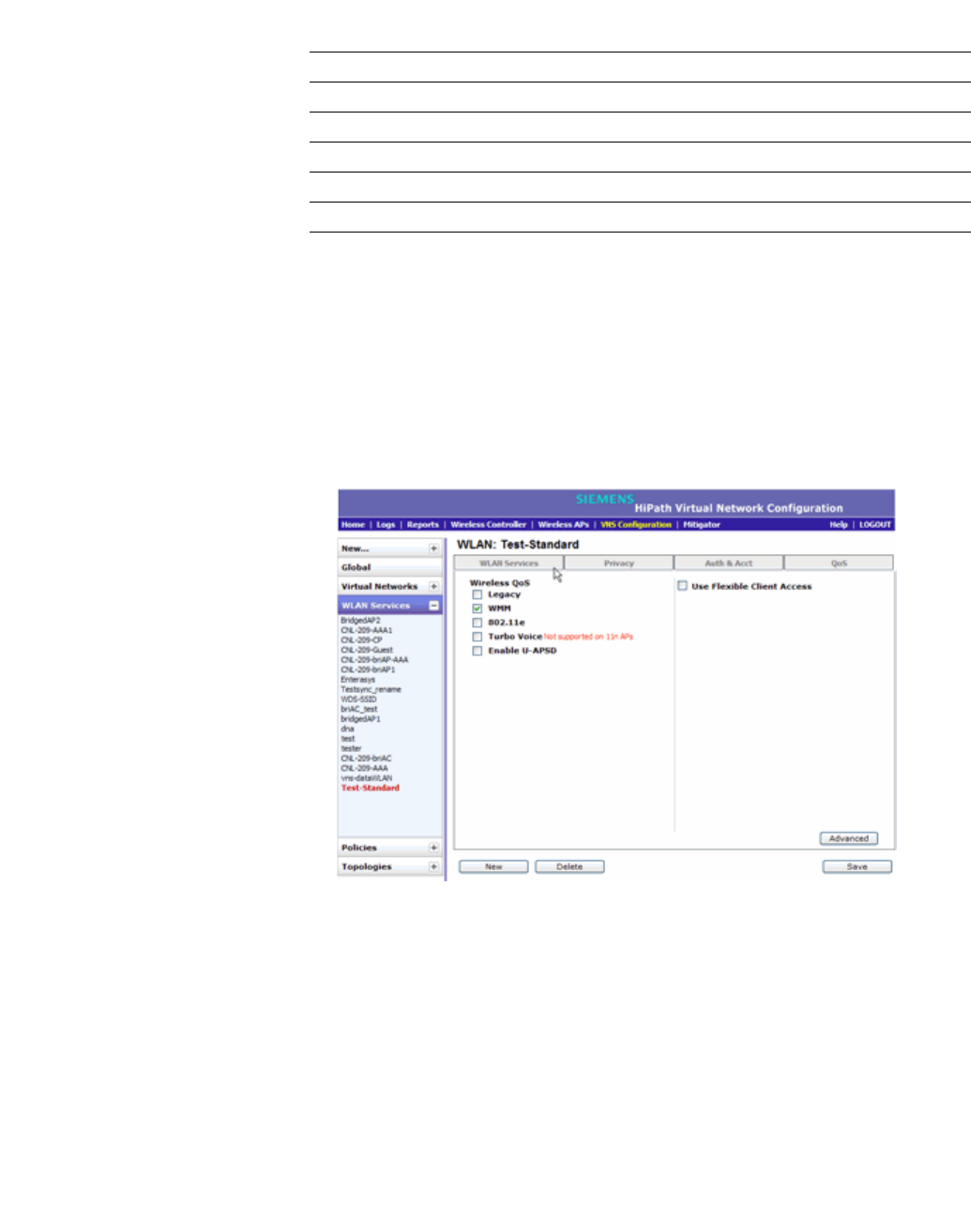
hwc_vnsconfiguration.fm
Configuring a VNS
Configuring WLAN Services
9034530-02, March 2010
HiPath Wireless Controller, Access Points and Convergence Software V7.11, User Guide 347
.
Table 27 Traffic prioritization
To configure QoS Policy:
1. From the main menu, click Virtual Network Configuration. The Virtual
Network Configuration screen is displayed.
2. In the left pane expand the WLAN Services pane, then click the WLAN
Service. The WLAN Services configuration page is displayed.
3. Click the QoS tab.
4. From the Wireless QoS list, do the following:
•Legacy – Select if your service will support legacy devices.
•WMM – Select to enable the AP to accept WMM client associations, and
classify and prioritize the downlink traffic for all WMM clients. Note that
WMM clients will also classify and prioritize the uplink traffic. WMM is part
of the 802.11e standard for QoS. If selected, the Turbo Voice and
Enable U-APSD options are displayed.
VNS type Packet Source Packet type L2 L3
Tunneled Wired Untagged No Yes
Branch Wired VLAN tagged Yes Yes
Branch Wired Untagged No Yes
Branch or Tunneled Wireless WMM Yes Yes
Branch or Tunneled Wireless non-WMM No Yes
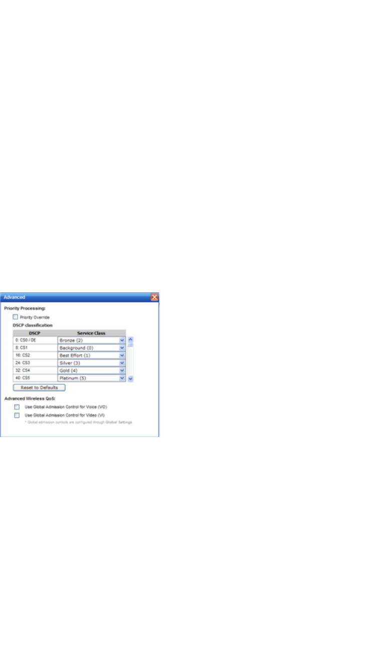
Configuring a VNS
hwc_vnsconfiguration.fm
Configuring WLAN Services
9034530-02, March 2010
348 HiPath Wireless Controller, Access Points and Convergence Software V7.11, User Guide
• 802.11e – Select to enable the AP to accept WMM client associations,
and classify and prioritize the downlink traffic for all 802.11e clients. The
802.11e clients will also classify and prioritize the uplink traffic. If selected,
the Turbo Voice and the Enable U-APSD options are displayed:
• Turbo Voice – Select to enable all downlink traffic that is classified to the
Voice (VO) AC and belongs to that VNS to be transmitted by the AP via
a queue called Turbo Voice (TVO) instead of the normal Voice (VO)
queue. When Turbo Voice is enabled together with WMM or 802.11e, the
WMM and/or 802.11e clients in that VNS are instructed by the AP to
transmit all traffic classified to VO AC with special contention parameters
tailored to maximize voice performance and capacity.
• Enable U-APSD – Select to enable the Unscheduled Automatic Power
Save Delivery (U-APSD) feature. This feature can be used by mobile
devices to efficiently sustain one or more real-time streams while being in
power-save mode. This feature works in conjunction with WMM and/or
802.11e, and it is automatically disabled if both WMM and 802.11e are
disabled.
5. To configure advanced QoS policy settings, click Advanced. The Advanced
dialog is displayed.
6. To force a service class and DSCP marking, select the Priority Override
checkbox. For the Service Class selection, you can click one of the eight
service classes.
• Service class – From the drop-down list, click the appropriate priority
level:
•Network control (7) – The highest priority level.
•Premium (Voice) (6)
•Platinum (5)
•Gold (4)
•Silver (3)

hwc_vnsconfiguration.fm
Configuring a VNS
Configuring WLAN Services
9034530-02, March 2010
HiPath Wireless Controller, Access Points and Convergence Software V7.11, User Guide 349
•Bronze (2)
•Best Effort (1)
•Background (0) – The lowest priority level
• DSCP marking – From the drop-down list, click the DSCP value used to
tag the IP header of the encapsulated packets.
When Priority Override is enabled, the configured service class forces
queue selection in the downlink direction, the 802.1P user priority for the
VLAN tagged Ethernet packets and the user priority for the wireless QoS
packets (WMM or 802.11e), according to the mapping between service class
and user priority. If Priority Override is enabled and the VNS is not locally
bridged, the configured DSCP value is used to tag the IP header of the
encapsulated packets. The AP does not override the DSCP in the IP header
of the user packet.
7. If you want to assign a service class to each DSCP marking, clear the Priority
Override checkbox and define the DSCP service class priorities in the DSCP
classification table.
8. The Advanced Wireless QoS options are only displayed if the WMM or
802.11e checkboxes are selected:
• Use Global Admission Control for Voice (VO) – Select to enable
admission control for Voice. With admission control, clients are forced to
request admission in order to use the high priority access categories in
both downlink and uplink direction. Admission control protects admitted
traffic against new bandwidth demands.
• Use Global Admission Control for Video (VI) – This feature is only
available If admission control is enabled for Voice. Select to enable
admission control for Video. With admission control, clients are forced to
request admission in order to use the high priority access categories in
both downlink and uplink direction. Admission control protects admitted
traffic against new bandwidth demands.
•UL Policer Action – If Use Global Admission Control for Voice (VO)
or Use Global Admission Control for Video (VI) is enabled, click the
action you want the Wireless AP to take when TSPEC violations
occurring on the uplink direction are discovered:
• Do nothing – Click to allow TSPEC violations to continue when they
are discovered. Data transmissions will continue and no action is
taken against the violating transmissions.
• Send DELTS to Client – Click to end TSPEC violations when it they
are discovered. This action deletes the TSPEC.

Configuring a VNS
hwc_vnsconfiguration.fm
Configuring Policy
9034530-02, March 2010
350 HiPath Wireless Controller, Access Points and Convergence Software V7.11, User Guide
• DL Policer Action – If Use Global Admission Control for Voice (VO)
or Use Global Admission Control for Video (VI) is enabled, click the
action you want the Wireless AP to take when TSPEC violations
occurring on the downlink direction are discovered:
• Do nothing – Click to allow TSPEC violations to continue when they
are discovered. Data transmissions will continue and no action is
taken against the violating transmissions.
• Downgrade – Click to force the transmission’s data packets to be
downgraded to the next priority when a TSPEC violation is
discovered.
•Drop – Click to force the transmission’s data packets to be dropped
when a TSPEC violation is discovered.
9. Close the Advanced window.
10. Check the Use Flexible Client Access checkbox to enable flexible client
access. Flexibe client access levels are set as part of the VNS global settings.
11. To save your changes, click Save.
6.10 Configuring Policy
Policy configuration defines the binding of a Topology(VLAN), ingress and egress
Rate Profiles applied to the traffic of a station, and filter rules.
In general, Class of Service refers to a set of attributes that define the importance
of a frame while it is forwarded through the network relative to other packets, and
to the maximum throughput per time unit that a station or port assigned to the
policy is permitted. The Class of Service defines actions to be taken when rate
limits are exceeded.
On the HiPath Wireless Controller, configuration of the CoS is part of a WLAN
Service while the Rate Control and Filtering are part of Policy definition.
Policies don't need to be fully specified; Unspecified attributes are retained by
the user or inherited from Global Policy definitions (see Section 6.2.6,
“Configuring the Global Default Policy”, on page 254 for more information).
Default Global Policy definitions provide a placeholder for completion of
incomplete policies for initial default assignment. If a policy is defined as Default
for a particular VNS, incomplete (NO-CHANGE) attributes are inherited from
Default Global Policy Definitions
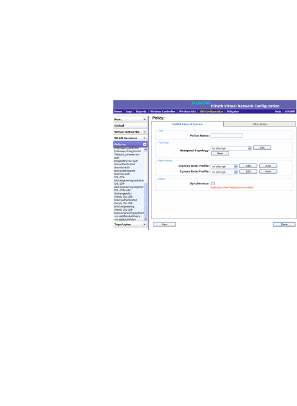
hwc_vnsconfiguration.fm
Configuring a VNS
Configuring Policy
9034530-02, March 2010
HiPath Wireless Controller, Access Points and Convergence Software V7.11, User Guide 351
6.10.1 Configuring VLAN and Class of Service for a
Policy
1. From the main menu, click Virtual Network Configuration. The Virtual
Network Configuration screen is displayed.
2. In the left pane expand the Policies pane and click the Policy you want to
edit, or click the New button to create a new Policy. The Policy window is
displayed.
3. Select the VLAN & Class of Service tab.
4. In the Core area, enter the name of the policy.
5. In the Topology area, select an existing topology from the Assigned
Topology drop-down list, or click the New button to create a new topology.
To edit an existing topology, select the topology and then click the Edit button.
Refer to Section 6.8, “Configuring a Topology”, on page 296 for information
about configuring a topology.
6. In the Rate Profiles area, select an existing Ingress and/or Egress Rate
Profile from the drop-down lists, or click the New button to create a new rate
control profile. To edit an existing profile, click Edit.
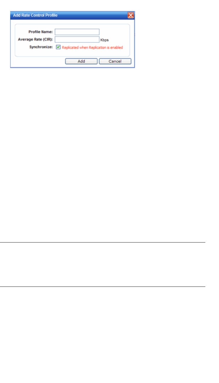
Configuring a VNS
hwc_vnsconfiguration.fm
Configuring Policy
9034530-02, March 2010
352 HiPath Wireless Controller, Access Points and Convergence Software V7.11, User Guide
7. In the Add or Edit Rate Control Profile dialog, do the following:
a) Enter the name of the new profile.
b) Enter a value for the Average Rate (Committed Information Rate) in Kbps.
c) Enable or disable synchronization.
d) Click Add to save your changes and return to the VLAN & Class of
Service tab.
Refer to Section 6.2.5, “Working with bandwidth control profiles”, on page 253
for more information.
8. If desired, enable synchronization by selecting the Synchronize checkbox.
9. Click Save to save your changes.
6.10.2 About filtering rules
The next step in configuring a Policy is to define the filter rules. The Policy name
should match filter ID values set up on the RADIUS servers.
Note: This configuration step is optional. If filter ID values are not defined, the
system uses the default filter as the applicable filter for authenticated users.
However, if more user-specific filter definitions are required, for example filters
based on a user’s department, then the filter ID configuration is used to identify
the specific Policy that should be applied to the user.
The filter definition can be static on the HiPath Wireless Controller itself, or the
filter definition can be set to be dynamically provisioned if RADIUS authentication
is used. The standard RADIUS attribute can be used to identify a specific filter
definition to apply to incoming/outgoing user traffic upon successful
authentication of the user during authentication.
Configuring filtering rules/Policy in the case of SSID network assignment
The SSID network assignment type offers the following three default filters:
•Exception

hwc_vnsconfiguration.fm
Configuring a VNS
Configuring Policy
9034530-02, March 2010
HiPath Wireless Controller, Access Points and Convergence Software V7.11, User Guide 353
•Non-authenticated
•Default
Configuring filtering rules for a Non-authenticated filter
The rules for a Non-authenticated filter enable you to identify and manage the
destinations to which a mobile device is allowed to gain access without
undergoing an authentication redirection. Typically, the recommended default
rule is to deny all. Administrators must define the rules that will permit users to
access essential services such as the following:
•DNS
•Default Gateway (VNS interface IP for routed VNSs)
Any HTTP streams requested by the client for denied targets will be redirected to
the specified location.
Configuring filtering rules for Default filter
The Default filter is applied by default (automatically) after the authentication of
the wireless device under the following circumstances:
•No match is found in the Exception filter rules
•No filter ID attribute value is returned by the authentication server for the
device
•No Policy name match to the filter ID value is found
In order to ensure that a packet is not dropped entirely under the above
circumstances, the final rule in the Default filter must be Allow All.
Configuring filtering rules/Policy in the case of AAA network assignment
The AAA network assignment type offers the following two default filters:
•Default
•Exception
In AAA network assignment type, a Non-authenticated filter becomes
unnecessary because the users are already authenticated.
6.10.3 Configuring Filter Rules for a Policy
Defining non-authenticated filters allows administrators to identify destinations to
which a mobile user is allowed to access without incurring an authentication
redirection. Typically, the recommended default rule is to deny all. Administrators
should define a rule set that will permit users to access essential services:
•DNS (IP of DNS server)

Configuring a VNS
hwc_vnsconfiguration.fm
Configuring Policy
9034530-02, March 2010
354 HiPath Wireless Controller, Access Points and Convergence Software V7.11, User Guide
•Default Gateway (VNS Interface IP)
Any HTTP streams requested by the client for denied targets will be redirected to
the specified location.
The non-authenticated filter should allow access to the Captive Portal page IP
address, as well as to any URLs for the header and footer of the Captive Portal
page. This filter should also allow network access to the IP address of the DNS
server and to the network address—the gateway of the Topology. The gateway
is used as the IP for an internal Captive Portal page. An external Captive Portal
will provide a specific IP definition of a server outside the HiPath Wireless
Controller.
Redirection and Captive Portal credentials apply to HTTP traffic only. A wireless
device user attempting to reach Websites other than those specifically allowed in
the non-authenticated filter will be redirected to the allowed destinations. Most
HTTP traffic outside of those defined in the non-authenticated filter will be
redirected.
Note: Although non-authenticated filters definitions are used to assist in the
redirection of HTTP traffic for restricted or denied destinations, the non-
authenticated filter is not restricted to HTTP operations. The filter definition is
general. Any traffic other than HTTP that the filter does not explicitly allow will be
discarded by the controller.
The non-authenticated filter is applied by the HiPath Wireless Controller to
sessions until they successfully complete authentication. The authentication
procedure results in an adjustment to the user's applicable filters for access
policy.
Typically, default filter ID access is less restrictive than a non-authenticated
profile. It is the administrator’s responsibility to define the correct set of access
privileges.
To define filtering rules for a non-authenticated filter:
1. From the main menu, click Virtual Network Configuration. The Virtual
Network Configuration screen is displayed.
2. In the left pane expand the Policies pane and click the Policy you want to
edit, or click the New button to create a new Policy. The Policy tab is
displayed.
3. Click the Filter Rules tab. The HWC Filters tab displays, allowing you to
create filter rules that will be applied by the controller.
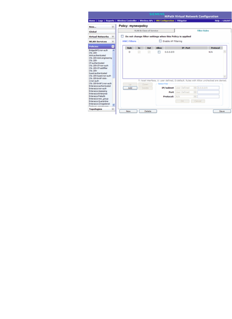
hwc_vnsconfiguration.fm
Configuring a VNS
Configuring Policy
9034530-02, March 2010
HiPath Wireless Controller, Access Points and Convergence Software V7.11, User Guide 355
The HWC Filters tab automatically provides a Deny All rule already in place.
Use this rule as the final rule in the non-authenticated filter for Captive Portal.
4. If you do not want the currently applied filter settings to change when this
Policy is applied, check the Do not change checkbox.
5. To add a rule, click Add. The fields in the Add Filter area are enabled.
6. From the IP/subnet drop-down list, select one of the following:
•User Defined, then type the destination IP address and mask.
Use this option to explictly define the IP/subnet aspect of the filter rule.
•IP. Use this option to map the rule to the associated Topology IP address.
• Subnet. Use this option to map the rule to the associated Topology
segment definition (IP address/mask).
7. From the Port drop-down list, select one of the following:
•User Defined, then type the port number.
Use this option to explicitly specify the port number.
•A specific port type. The appropriate port number or numbers are added
to the Port text field.

Configuring a VNS
hwc_vnsconfiguration.fm
Configuring Policy
9034530-02, March 2010
356 HiPath Wireless Controller, Access Points and Convergence Software V7.11, User Guide
8. In the Protocol drop-down list, click the applicable protocol. The default is
N/A. Refer to Section 6.10.4, “ICMP Type enforcement”, on page 358 for
more information when selecting the ICMP protocol.
Note: For Captive Portal assignment, define a rule to allow access to the
default gateway for this controller. You should also configure a rule denying
HTTP on the controller.
9. Click OK. The information is displayed in the HWC Filters rule table.
10. Click the new filter in the rule table, then do the following:
•If applicable, select In to refer to traffic from the network host that is trying
to get to a wireless device.
•If applicable, select Out to refer to traffic from the wireless device that is
trying to get on the network.
•Select the Allow checkbox applicable to the rule you defined.
11. To edit the order of filters, click the filter, and then click the Up and Down
buttons. The filtering rules are executed in the order you define here.
12. To save your changes, click Save.
Note: Administrators must ensure that the non-authenticated filter allows
access to the corresponding authentication server:
• Internal Captive Portal – IP address of the VNS interface
• External Captive Portal – IP address of external Captive Portal server
6.10.3.1 Non-authenticated filter examples
A basic non-authenticated filter for internal Captive Portal should have three
rules, in the following order:

hwc_vnsconfiguration.fm
Configuring a VNS
Configuring Policy
9034530-02, March 2010
HiPath Wireless Controller, Access Points and Convergence Software V7.11, User Guide 357
Note: For external Captive Portal, an additional rule to Allow (in/out) access to
the external Captive Portal authentication/Web server is required.
If you place URLs in the header and footer of the Captive Portal page, you must
explicitly allow access to any URLs mentioned in the authentication's server
page, such as:
• Internal Captive Portal – URLs referenced in a header or footer
• External Captive Portal – URLs mentioned in the page definition
Here is another example of a non-authenticated filter that adds two more filtering
rules. The two additional rules do the following:
•Deny access to a specific IP address.
•Allows only HTTP traffic.
Once a wireless device user has logged in on the Captive Portal page, and has
been authenticated by the RADIUS server, then the following filters will apply:
• Policy filters – If a filter ID associated with this user was returned by the
authentication server, then the Policy with the same name as the filter ID will
be applied.
In Out Allow IP / Port Description
x x x IP address of default
gateway (VNS Interface
IP)
Allow all incoming wireless devices
access to the default gateway of the VNS.
x x x IP address of the DNS
Server
Allow all incoming wireless devices
access to the DNS server of the VNS.
x x *.*.*.* Deny everything else.
Table 28 Non-authenticated filter example A
In Out Allow IP / Port Description
x x x IP address of the default
gateway
Allow all incoming wireless devices
access to the default gateway of the VNS.
x x x IP address of the DNS
Server
Allow all incoming wireless devices
access to the DNS server of the VNS.
x x [a specific IP address, or
address plus range]
Deny all traffic to a specific IP address, or
to a specific IP address range (such
as:0/24).
x x x *.*.*.*:80 Allow all port 80 (HTTP) traffic.
x x *.*.*.* Deny everything else.
Table 29 Non-authenticated filter example B

Configuring a VNS
hwc_vnsconfiguration.fm
Configuring Policy
9034530-02, March 2010
358 HiPath Wireless Controller, Access Points and Convergence Software V7.11, User Guide
• Default filter – If no matching filter ID was returned from the authentication
server.
6.10.3.2 Authenticated filter examples
Below are two examples of possible filtering rules for authenticated users. The
first example disallows some specific access before allowing everything else.
The second example does the opposite of the first example. It allows some
specific access and denies everything else.
6.10.4 ICMP Type enforcement
ICMP filter rules can now be constrained to ICMP type/range. You can define the
ICMP type/range in the Port field using the TCP/UDP port definition
nomenclature. That is, define the rule as a normal IP/subnet:port signature
(10.0.0.0/24:8), where the ICMP type is entered in the Port field.
This feature allows for tighter granularity over enforcement of ICMP restrictions.
You can allow redirects and DF/MTU indications, and deny ICMP Echo (pings)
for users.
6.10.5 Filtering rules for a default filter
After authentication of the wireless device user, the default filter will apply only
after:
•No match is found for the Exception filter rules.
In Out Allow IP / Port Description
x x *.*.*.*:22-23 SSH and telnet sessions
x x [specific IP address,
range]
Deny all traffic to a specific IP address
or address range
x x x *.*.*.*. Allow everything else
Table 30 Filtering rules example A
In Out Allow IP / Port Description
x x x [specific IP address,
range]
Allow traffic to a specific IP address or
address range.
x x *.*.*.*. Deny everything else.
Table 31 Filtering rules example B

hwc_vnsconfiguration.fm
Configuring a VNS
Configuring Policy
9034530-02, March 2010
HiPath Wireless Controller, Access Points and Convergence Software V7.11, User Guide 359
•No filter ID attribute value is returned by the authentication server for this
user.
•No Policy match is found on the HiPath Wireless Controller for the filter ID
value.
The final rule in the default filter should be a catch-all rule for any traffic that did
not match a filter. A final Allow All rule in a default filter will ensure that a packet
is not dropped entirely if no other match can be found. VNS Policy is also
applicable for Captive Portal and MAC-based authorization.
6.10.5.1 Default filter examples
The following are examples of filtering rules for a default filter:
6.10.5.2 Filtering rules between two wireless devices
Traffic from two wireless devices that are on the same VNS and are connected to
the same Wireless AP will pass through the HiPath Wireless Controller and
therefore be subject to filtering policy. You can set up filtering rules that allow each
wireless device access to the default gateway, but also prevent each device from
communicating with each other.
Add the following two rules to a filter ID filter, before allowing everything else:
In Out Allow IP / Port Description
x x Intranet IP, range Deny all access to an IP range
x x Port 80 (HTTP) Deny all access to Web browsing
x x Intranet IP Deny all access to a specific IP
x x x *.*.*.*. Allow everything else
Table 32 Default filter example A
In Out Allow IP / Port Description
x Port 80 (HTTP) on host IP Deny all incoming wireless devices
access to Web browsing the host
x Intranet IP 10.3.0.20, ports
10-30
Deny all traffic from the network to the
wireless devices on the port range,
such as telnet (port 23) or FTP (port 21)
x x Intranet IP 10.3.0.20 Allow all other traffic from the wireless
devices to the Intranet network
x x Intranet IP 10.3.0.20 Allow all other traffic from Intranet
network to wireless devices
x x *.*.*.*. Deny everything else
Table 33 Default filter example B

Configuring a VNS
hwc_vnsconfiguration.fm
Configuring Policy
9034530-02, March 2010
360 HiPath Wireless Controller, Access Points and Convergence Software V7.11, User Guide
6.10.6 Defining filter rules for Wireless APs
You can also apply filter rules on the Wireless AP. Applying filter rules at the
Wireless AP helps restrict unwanted traffic at the edge of your network. The
Wireless APs can support up to a maximum of 32 filters rules per group. Filtering
at the Wireless AP can be configured with the following Topology types:
• Bridge Traffic Locally at the AP – If filtering at the Wireless AP is enabled
on a Bridge Traffic Locally at the AP topology, the filtering is applied to traffic
in both the uplink and downlink direction — the uplink direction is from the
wireless device to the network, and downlink direction is from the network to
the wireless device.
•Routed and Bridge Traffic Locally at the HWC – If filtering at the Wireless
AP is enabled on a Routed or Bridge Traffic Locally at the HWC topoloty, the
filtering is applied only to traffic in the UL direction. The filters applied in the
UL direction at the Wireless AP can be the same or different from filters
applied at the HiPath Wireless Controller.
Wireless AP filtering
When filtering at the Wireless AP is enabled, Wireless APs obtain client filter
information from the HiPath Wireless Controller. In addition, direct inter-Wireless
AP communication allow Wireless APs to exchange client filter information as
clients roam from one Wireless AP to another. This allows the system to achieve
a very fast roaming time. To take advantage of inter-Wireless AP communication,
you should configure the network so that Wireless APs in the mobility domain can
communicate with each other through the Wireless AP's Ethernet interface. Also,
multicast traffic with an IP address of 224.0.1.178 should be allowed between
Wireless APs.
To define filter rules to be applied by Wireless APs:
1. From the main menu, click Virtual Network Configuration. The Virtual
Network Configuration screen is displayed.
2. In the left pane expand the Policies pane and click the Policy you want to
edit, or click the New button to create a new Policy. The Policy tab is
displayed.
In Out Allow IP / Port Description
x x x [Intranet IP] Allow access to the Gateway IP address of the
VNS only
x x [Intranet IP, range] Deny all access to the VNS subnet range (such
as 0/24)
x x x *.*.*.*. Allow everything else
Table 34 Rules between two wireless devices

hwc_vnsconfiguration.fm
Configuring a VNS
Configuring Policy
9034530-02, March 2010
HiPath Wireless Controller, Access Points and Convergence Software V7.11, User Guide 361
3. Click the Filter Rules tab. The HWC Filters tab displays.
4. Select the Enable AP Filtering checkbox. This enables the filter rules
defined on the HWC Filters tab to be applied by Wireless APs.
5. If you want to configure additional filters for the APs, select the Custom AP
Filters checkbox. An AP Filters tab is added to the window. Click the AP
Filters tab to display it.
6. To add a rule, click Add. The fields in the Add Filter area are enabled.
7. From the IP/subnet drop-down list, select one of the following:
•User Defined, then type the destination IP address and mask.
Use this option to explictly define the IP/subnet aspect of the filter rule.
•IP. Use this option to map the rule to the associated Topology IP address.
• Subnet. Use this option to map the rule to the associated Topology
segment definition (IP address/mask).
8. From the Port drop-down list, select one of the following:
•User Defined, then type the port number.
Use this option to explicitly specify the port number.
•A specific port type. The appropriate port number or numbers are added
to the Port text field.
9. In the Protocol drop-down list, click the applicable protocol. The default is
N/A.
10. To add the new filter rule, click OK The filter rule is added to the filter group.
11. In the filter rule table, click the filter, and then do the following:
•If applicable, select Out to refer to traffic from the wireless device that is
trying to get on the network.
•If applicable, select In to refer to traffic from the network host that is trying
to get to a wireless device.
•Select the Allow checkbox applicable to the rule you defined.
12. To edit the order of filter rules, click the filter, and then click the Up and Down
buttons. The filtering rules are executed in the order you define here.
13. To save your changes, click Save.

Configuring a VNS
hwc_vnsconfiguration.fm
Working with a Wireless Distribution System
9034530-02, March 2010
362 HiPath Wireless Controller, Access Points and Convergence Software V7.11, User Guide
6.11 Working with a Wireless Distribution System
A Wireless Distribution System (WDS) enables you to expand the wireless
network by interconnecting the Wireless APs through wireless links in addition to
the traditional method of interconnecting Wireless APs via a wired network.
Note: The Scalance AP W788-2 and AP2605 do not support WDS.
A WDS deployment is ideally suited for locations, where installing ethernet
cabling is too expensive, or physically impossible.
The WDS can be deployed in three configurations:
•Simple WDS Configuration
•Wireless Repeater Configuration
•Wireless Bridge Configuration
6.11.1 Simple WDS configuration
In a typical configuration, the Wireless APs are connected to the distribution
system via an Ethernet network, which provides connectivity to the HiPath
Wireless Controller.
However, when a Wireless AP is installed in a remote location and can’t be wired
to the distribution system, an intermediate Wireless AP is connected to the
distribution system via the Ethernet link. This intermediate Wireless AP forwards
and receives the user traffic from the remote Wireless AP over a radio link.
The intermediate Wireless AP that is connected to the distribution system via the
Ethernet network is called Root AP, and the Wireless AP that is remotely located
is called the Satellite AP.
The following figure illustrates the Simple WDS configuration:
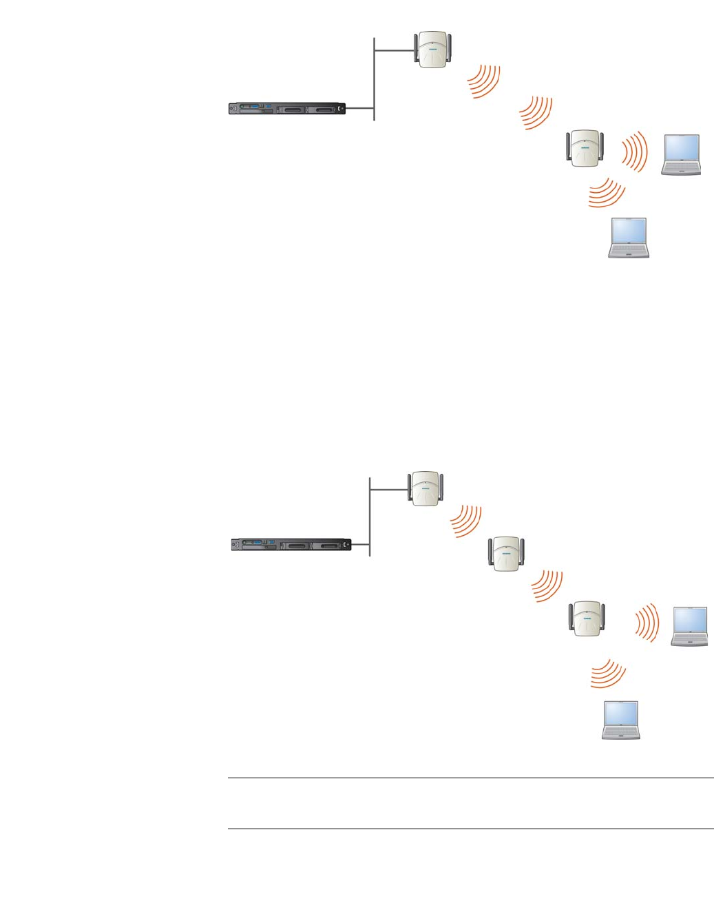
hwc_vnsconfiguration.fm
Configuring a VNS
Working with a Wireless Distribution System
9034530-02, March 2010
HiPath Wireless Controller, Access Points and Convergence Software V7.11, User Guide 363
Figure 14 Simple WDS configuration
6.11.2 Wireless Repeater configuration
In Wireless Repeater configuration, a Repeater Wireless AP is installed between
the Root Wireless AP and the Satellite Wireless AP. The Repeater Wireless AP
relays the user traffic between the Root Wireless AP and the Satellite Wireless
AP. This increases the WLAN range.
The following figure illustrates the Wireless Repeater configuration:
Figure 15 Wireless Repeater configuration
Note: You should restrict the number of repeater hops in a Wireless Repeater
configuration to three for optimum performance.
HiPath Wireless Controller
Root Wireless AP
Satellite Wireless AP
Client Devices
HiPath Wireless Controller
Root Wireless AP
Repeater Wireless AP
Client Devices
Satellite Wireless AP
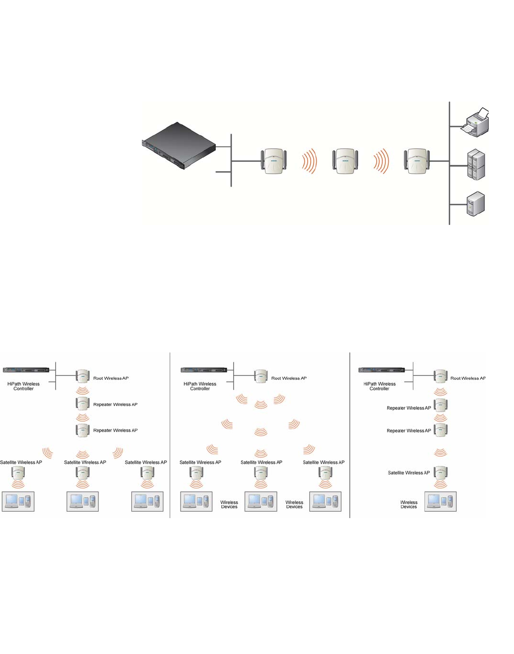
Configuring a VNS
hwc_vnsconfiguration.fm
Working with a Wireless Distribution System
9034530-02, March 2010
364 HiPath Wireless Controller, Access Points and Convergence Software V7.11, User Guide
6.11.3 Wireless Bridge configuration
In Wireless Bridge configuration, the traffic between two Wireless APs that are
connected to two separate wired LAN segments is bridged via WDS link. You
may also install a Repeater Wireless AP between the two Wireless APs
connected to two separate LAN segments.
Figure 16 Wireless Bridge configuration
When you are configuring the Wireless Bridge configuration, you must specify on
the user interface that the Satellite AP is connected to the wired LAN.
6.11.4 Examples of deployment
The following illustration depicts a few examples of WDS deployment.
Figure 17 Examples of WDS deployment
6.11.5 WDS WLAN Services
In a traditional HiPath WLAN deployment, each radio of the Wireless AP can
interact with the client devices on a maximum of eight networks.
HiPath Wireless
Controller Root AP Repeater AP Satellite AP
LAN Segment 1 LAN Segment 2
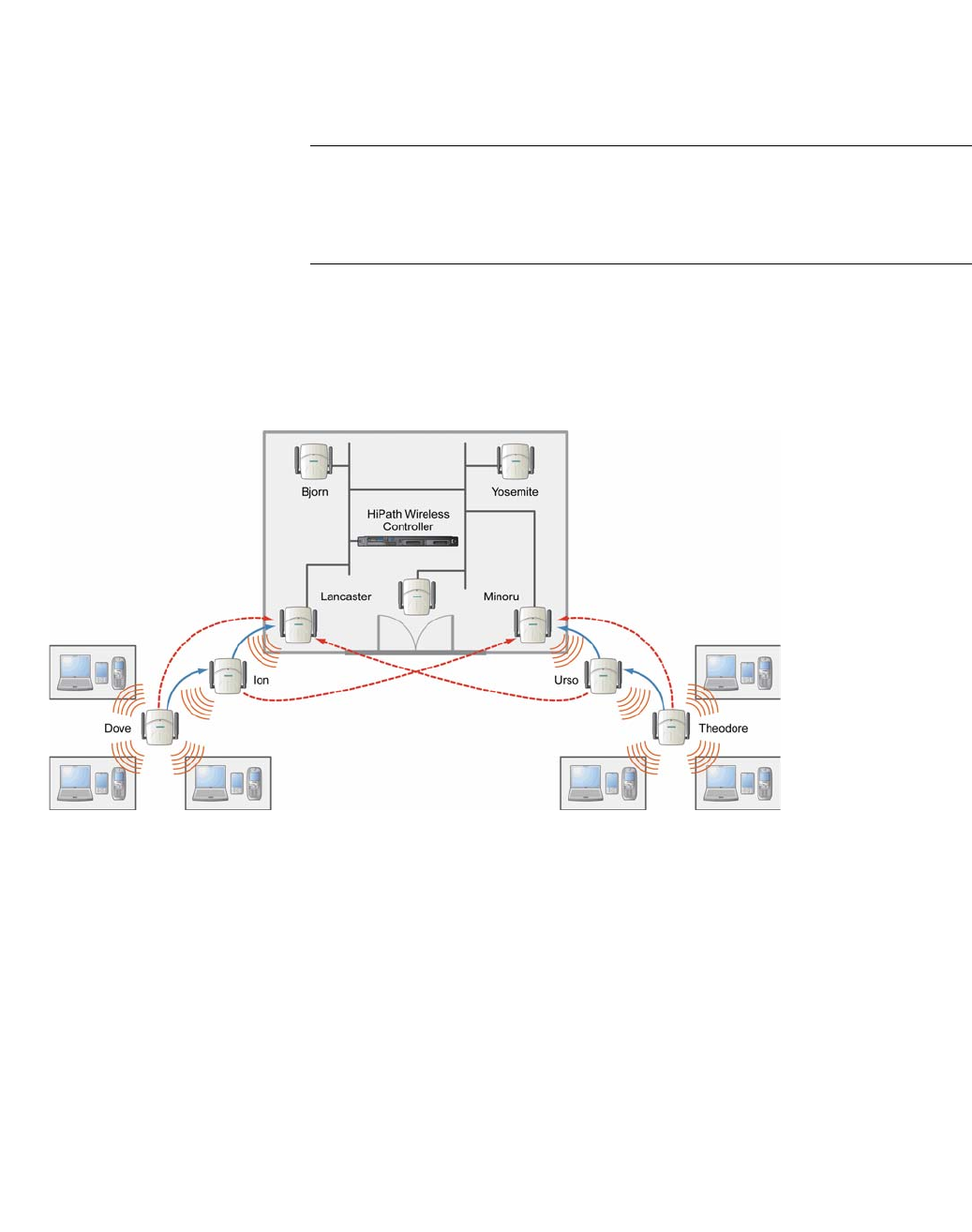
hwc_vnsconfiguration.fm
Configuring a VNS
Working with a Wireless Distribution System
9034530-02, March 2010
HiPath Wireless Controller, Access Points and Convergence Software V7.11, User Guide 365
In WDS deployment, one of the radios of every WDS Wireless AP establishes a
WDS link on an exclusive WLAN Service. The WDS Wireless AP is therefore
limited to seven network WLAN Services on the WDS radio. The other radio can
interact with the client-devices on a maximum of eight WLAN Services.
Note: The Root Wireless AP and the Repeater Wireless APs can also be
configured to interact with the client-devices. For more information, see Section
6.11.7.3, “Assigning the Satellite Wireless APs’ radios to the network WLAN
Services”, on page 377.
The WLAN Service on which the Wireless APs establish the WDS link is called
the WDS WLAN Service.
A WDS can be setup either by using either a single WDS WLAN Service or
multiple WDS WLAN Services. The following figures illustrate the point.
Figure 18 Deployment Example
WDS setup with a single WDS WLAN Service
Deploying the WDS for the above example using a single WDS WLAN Service
results in the following structure.
•The rectangular
enclosure denotes an
office building
•The four Wireless APs —
Minoru, Yosemite, Bjorn
and Lancaster — are
within the confines of the
building and are
connected to the wired
network.
•The space around the
office building is a ware
house.
•The solid arrows point
towards Preferred
Parents.
•The dotted arrows point
towards Backup Parents.
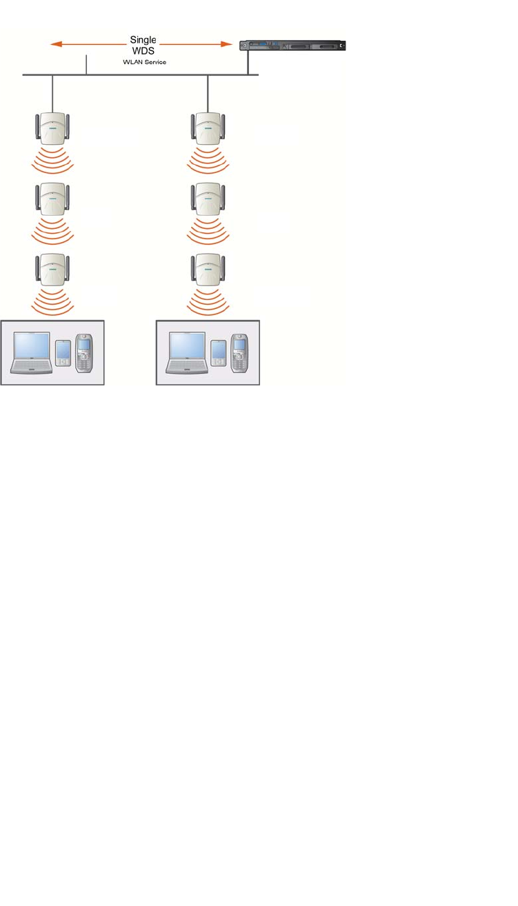
Configuring a VNS
hwc_vnsconfiguration.fm
Working with a Wireless Distribution System
9034530-02, March 2010
366 HiPath Wireless Controller, Access Points and Convergence Software V7.11, User Guide
Figure 19 WDS setup with a single WDS WLAN Service
The tree will operate as a single WDS entity. It will have a single WDS SSID and
and a single pre-shared key for WDS links. This tree will have multiple roots. For
more information, see Section 6.11.6.3, “Multi-root WDS topology”, on page 369.
WDS setup with multiple WDS WLAN Services
You can also deploy the same WDS in Figure 18 using two WDS WLAN Services.
The Two WDS WLAN Services will create two independent WDS trees. Both the
trees will operate on separate SSIDs and use separate pre-shared keys.
HiPath Wireless
Controller
Lancaster
Ion
Dove
Minoru
Urso
Theodore
Client
Devices
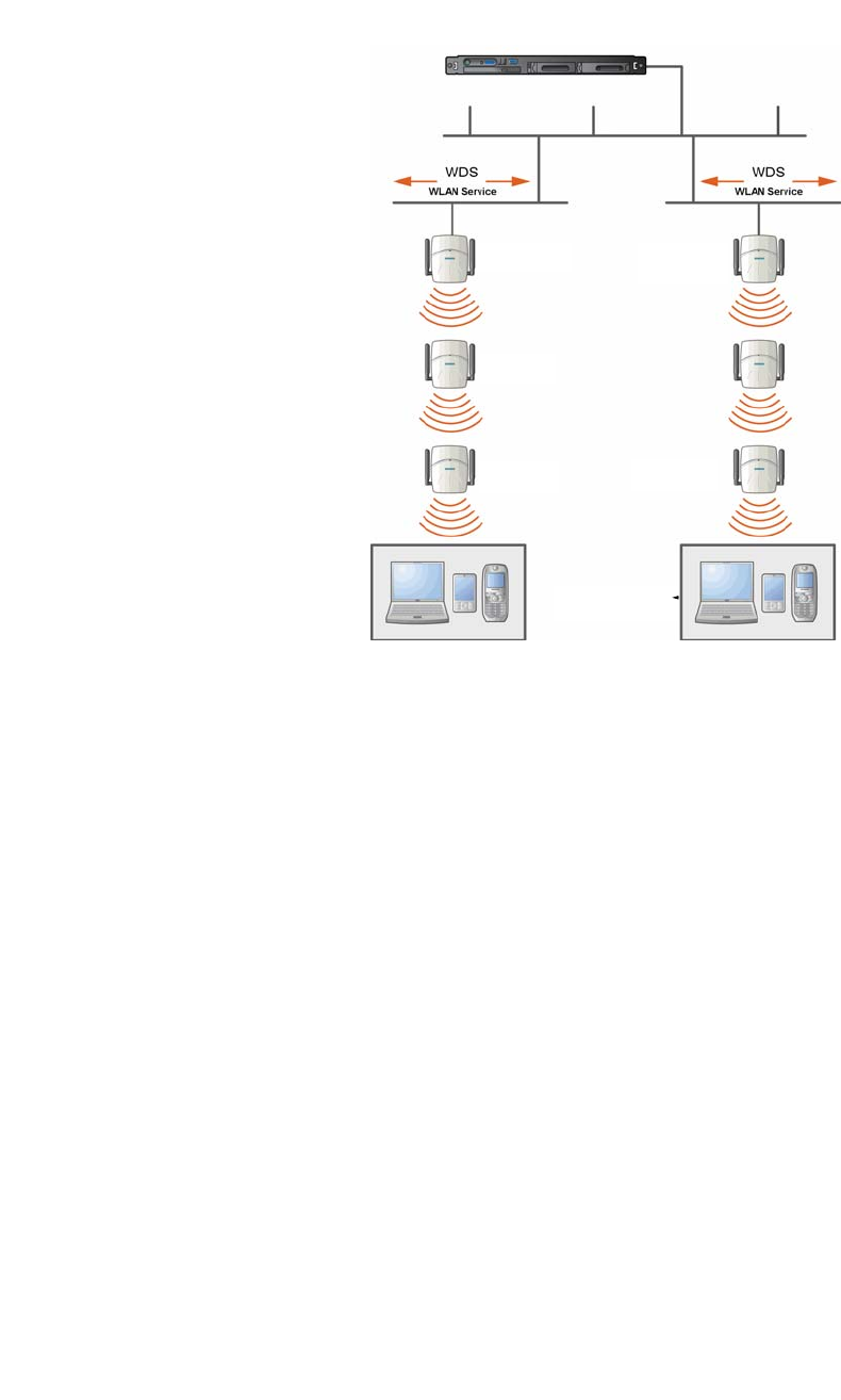
hwc_vnsconfiguration.fm
Configuring a VNS
Working with a Wireless Distribution System
9034530-02, March 2010
HiPath Wireless Controller, Access Points and Convergence Software V7.11, User Guide 367
Figure 20 WDS setup with multiple WDS WLAN Services
6.11.6 Key features of WDS
Some key features of WDS are:
•Tree-like topology
•Radio Channels
•Multi-root WDS topology
•Automatic discovery of parent and backup parent Wireless APs
•Link security
6.11.6.1 Tree-like topology
The Wireless APs in WDS configuration can be regarded as nodes, and these
nodes form a tree-like structure. The tree builds in a top down manner with the
Root Wireless AP being the tree root, and the Satellite Wireless AP being the tree
leaves.
Lancaster
Ion
Dove
Minoru
Theodore
Client Devices
Urso
HiPath Wireless
Controller
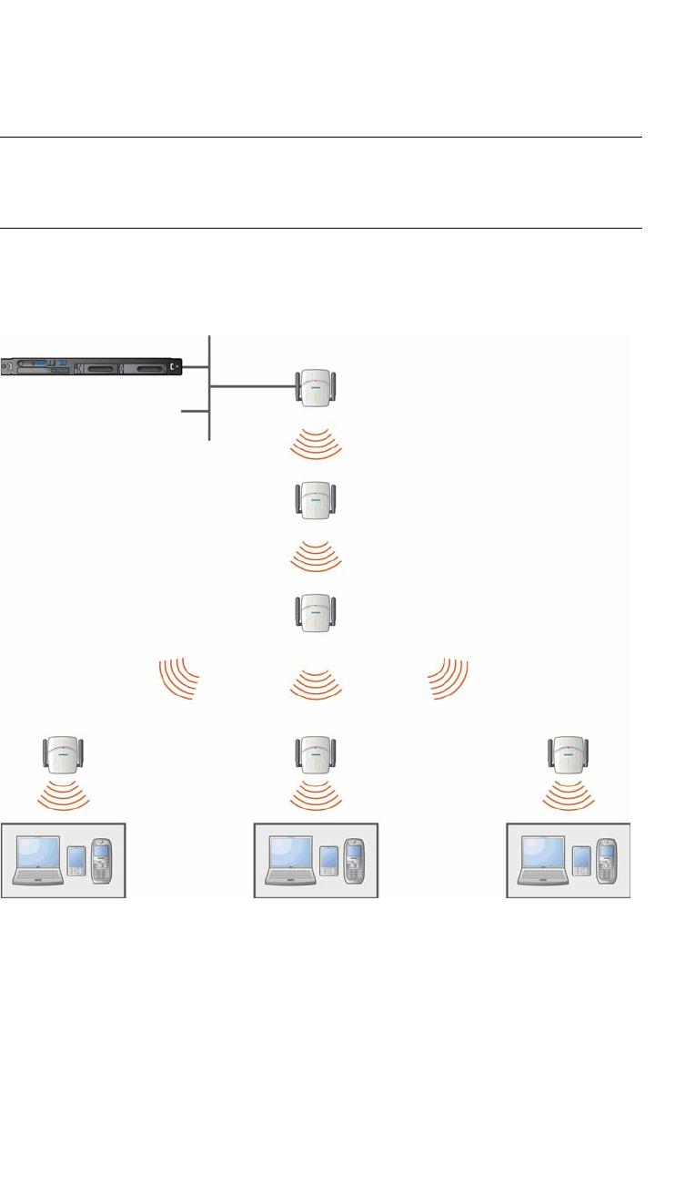
Configuring a VNS
hwc_vnsconfiguration.fm
Working with a Wireless Distribution System
9034530-02, March 2010
368 HiPath Wireless Controller, Access Points and Convergence Software V7.11, User Guide
The nodes in the tree-structure have a parent-child relationship. The Wireless AP
that provides the WDS service to the other Wireless APs in the downstream
direction is a parent. The Wireless APs that establish a link with the Wireless AP
in the upstream direction for WDS service are children.
Note: If a parent Wireless AP fails or stops to act a parent, the children Wireless
APs will attempt to discover their backup parents. If the backup parents are not
defined, the children Wireless APs will be left stranded.
The following figure illustrates the parent-child relationship between the nodes in
a WDS topology.
Figure 21 Parent-child relationship between Wireless APs in WDS
configuration
•Root Wireless AP is the parent of
Repeater Wireless AP 1.
•Repeater Wireless AP 1 is the child
of Root Wireless AP.
•Repeater Wireless AP 1 is the
parent of Repeater Wireless AP 2.
•Repeater Wireless AP 2 is the child
of Repeater Wireless AP 1.
•Repeater Wireless AP 2 is the
parent of the following Wireless
APs:
– Satellite Wireless AP 1
– Satellite Wireless AP 2
– Satellite Wireless AP 3
•All the three Satellite APs are the
children of Repeater Wireless AP 2.
HiPath Wireless
Controller
Repeater Wireless AP 1
Repeater Wireless AP 2
Satellite Wireless AP 1
Client Devices Client Devices
Satellite Wireless AP 2 Satellite Wireless AP 3
Root Wireless AP

hwc_vnsconfiguration.fm
Configuring a VNS
Working with a Wireless Distribution System
9034530-02, March 2010
HiPath Wireless Controller, Access Points and Convergence Software V7.11, User Guide 369
The WDS system enables you to configure the Wireless AP’s role — parent,
child or both — from the HiPath Wireless Controller’s interface. If the WDS
Wireless AP will be serving as a parent and a child in a given topology, its role is
configured as both.
Note: It is recommended to limit the number of APs participating in a WDS tree
to 8. This limit guarantees decent performance in most typical situations.
Note: If a Wireless AP is configured to serve as a scanner in Mitigator, it cannot
be used in a WDS tree. For more information, see Chapter 10, “Working with the
Mitigator”.
6.11.6.2 Radio Channels
The radio channel on which the child Wireless AP operates is determined by the
parent Wireless AP.
A Wireless AP may connect to its parent Wireless AP and children Wireless APs
on the same radio, or on different radios. Similarly, a Wireless AP can have two
children operating on two different radios.
Note: When a Wireless AP is connecting to its parent Wireless AP and children
APs on the same radio, it uses the same channel for both the connections.
6.11.6.3 Multi-root WDS topology
A WDS topology can have multiple Root Wireless APs. Figure 22 illustrates the
multiple-root WDS topology.
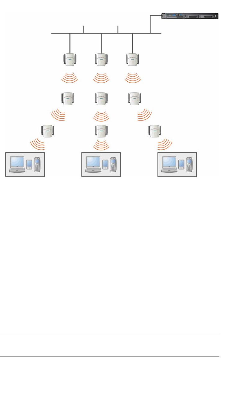
Configuring a VNS
hwc_vnsconfiguration.fm
Working with a Wireless Distribution System
9034530-02, March 2010
370 HiPath Wireless Controller, Access Points and Convergence Software V7.11, User Guide
Figure 22 Multiple-root WDS topology
6.11.6.4 Automatic discovery of parent and backup parent
Wireless APs
The children Wireless APs, including the Repeater Wireless AP and the Satellite
Wireless APs, scan for their respective parents at a startup.
You can configure a parent and backup parent for the children Wireless APs. The
Wireless APs will first try to negotiate a WDS link with the parent Wireless AP. If
the WDS link negotiation is unsuccessful, the Wireless AP will try to negotiate a
link with the backup parent.
6.11.6.5 Link security
The WDS link is encrypted using Advance Encryption Standard (AES).
Note: The keys for AES are configured prior to deploying the Repeater or
Satellite Wireless APs.
HiPath Wireless
Controller
Root Wireless AP 1 Root Wireless AP 2 Root Wireless AP 3
Repeater AP 1 Repeater AP 2 Repeater AP 3
Satellite AP 1 Satellite AP 2 Satellite AP 3
Wireless
Devices
Wireless
Devices

hwc_vnsconfiguration.fm
Configuring a VNS
Working with a Wireless Distribution System
9034530-02, March 2010
HiPath Wireless Controller, Access Points and Convergence Software V7.11, User Guide 371
6.11.7 Deploying the WDS system
Before you start configuring the WDS Wireless APs, you must ensure the
following:
•The Wireless APs that are part of the wired HiPath WLAN are connected to
the wired network.
•The wired Wireless APs that will serve as the Root AP/Root APs of the
proposed WDS topology are operating normally.
•The HiPath WLAN is operating normally.
Sketching the WDS topology
You may sketch the proposed WLAN topology on a paper before you start the
WDS deployment process. You should clearly identify the following in the sketch:
•WDS Wireless APs with their names
•Parent-Child relationships between Wireless APs
•Radios that you will choose to link the Wireless AP’s parents and children
Provisioning the WDS Wireless APs
This step is of crucial importance and involves connecting the WDS Wireless APs
to the enterprise network via the Ethernet link. This is done to enable the WDS
Wireless APs to connect to the HiPath Wireless Controller so that they can derive
their WDS configuration.
The WDS Wireless AP’s configuration includes pre-shared key, its role, preferred
parent name and the backup parent name.
Note: The provisioning of WDS Wireless APs must be done before they are
deployed at the target location. If the Wireless APs are not provisioned, they will
not work at their target location.
WDS deployment overview
The following is the high-level overview of the WDS deployment process:
1. Connecting the WDS Wireless APs to the enterprise network via the Ethernet
network to enable them to discover and register themselves with the HiPath
Wireless Controller. For more information, see Section 4.2, “Discovery and
registration overview”, on page 97.
2. Disconnecting the WDS Wireless APs from the enterprise network after they
have discovered and registered with the HiPath Wireless Controller.
3. Creating a WDS VNS.
4. Assigning roles, parents and backup parents to the WDS Wireless APs.

Configuring a VNS
hwc_vnsconfiguration.fm
Working with a Wireless Distribution System
9034530-02, March 2010
372 HiPath Wireless Controller, Access Points and Convergence Software V7.11, User Guide
5. Assigning the Satellite Wireless APs’ radios to the network VNSs.
6. Connecting the WDS Wireless APs to the enterprise network via the Ethernet
link for provisioning. For more information, see Section 6.11.7, “Provisioning
the WDS Wireless APs”, on page 371.
7. Disconnecting the WDS Wireless APs from the enterprise network and
moving them to the target location.
Note: During the WDS deployment process, the WDS Wireless APs are
connected to the enterprise network on two occasions — first to enable them to
discover and register with the HiPath Wireless Controller, and then the second
time to enable them to obtain the provisioning from the HiPath Wireless
Controller.
6.11.7.1 Connecting the WDS Wireless APs to the enterprise
network for discovery and registration
Connect each WDS Wireless AP to the enterprise network to enable it to discover
and register themselves with the HiPath Wireless Controller.
Note: Before you connect the WDS Wireless APs to the enterprise network for
discovery and registration, you must ensure that the Security mode property of
the HiPath Wireless Controller is defined according to your security needs. The
Security mode property dictates how the HiPath Wireless Controller behaves
when registering new and unknown devices. For more information, see Section
4.2.5, “Defining properties for the discovery process”, on page 115.
If the Security mode is set to Allow only approved Wireless APs to connect
(this is also known as secure mode), you must manually approve the WDS
Wireless APs after they are connected to the network for the discovery and
registration. For more information, see Section 4.3, “Adding and registering a
Wireless AP manually”, on page 118.
Depending upon the number of Ethernet ports available, you may connect one or
more WDS Wireless APs at a time, or you may connect all of them together.
Once a WDS Wireless AP has discovered and registered itself with the HiPath
Wireless Controller, disconnect it from the enterprise network.
6.11.7.2 Configuring the WDS Wireless APs through the HiPath
Wireless Controller
Configuring the WDS Wireless APs involves the following steps:
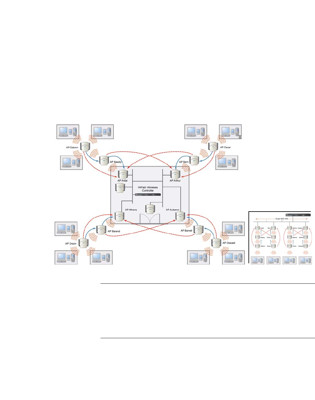
hwc_vnsconfiguration.fm
Configuring a VNS
Working with a Wireless Distribution System
9034530-02, March 2010
HiPath Wireless Controller, Access Points and Convergence Software V7.11, User Guide 373
1. Creating a WDS WLAN Service.
2. Defining the SSID name and the pre-shared key.
3. Assigning roles, parents and backup parents to the WDS Wireless APs.
For the ease of understanding, the WDS configuration process is explained with
the help of an example. The following illustration depicts a site with the following
features:
•An office building, denoted by a rectangular enclosure.
•Four Wireless APs — Ardal, Arthur, Athens and Auberon — are within the
confines of the building, and are connected to the wired network.
•The space around the building is the warehouse.
Figure 23 WDS Deployment
Note: With the single WDS VNS, the tree structure for the WDS deployment will
be as depicted on the bottom right of Figure 23. You can also implement the same
deployment using four WDS VNSs, each for a set of Wireless APs in the four
corners of the building. Each set of Wireless APs will form an isolated topology
and will operate using a separate SSID and a separate Pre-shared key. For more
information, see Section 6.11.5, “WDS WLAN Services”, on page 364.
•The solid arrows
point toward
Preferred
Parents.
•The dotted
arrows point
toward Backup
Parents.
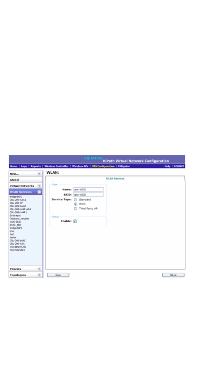
Configuring a VNS
hwc_vnsconfiguration.fm
Working with a Wireless Distribution System
9034530-02, March 2010
374 HiPath Wireless Controller, Access Points and Convergence Software V7.11, User Guide
To configure the WDS Wireless APs through the HiPath Wireless
Controller:
Note: You must identify and mark the Preferred Parents, Backup Parents and the
Child Wireless APs in the proposed WDS topology before starting the
configuration process.
1. From the main menu, click Virtual Network Configuration. The Virtual
Network Configuration screen is displayed.
2. In the left pane, expand the WLAN Services pane and select a WDS service
to edit or click the New button.
3. Enter a name for the service in the Name field.
4. The SSID field is automatically filled in with the name, but you can change it
if desired.
5. For Service Type, select WDS.
6. To save your changes, click Save. The WLAN configuration window is re-
displayed to show additional configuration fields.
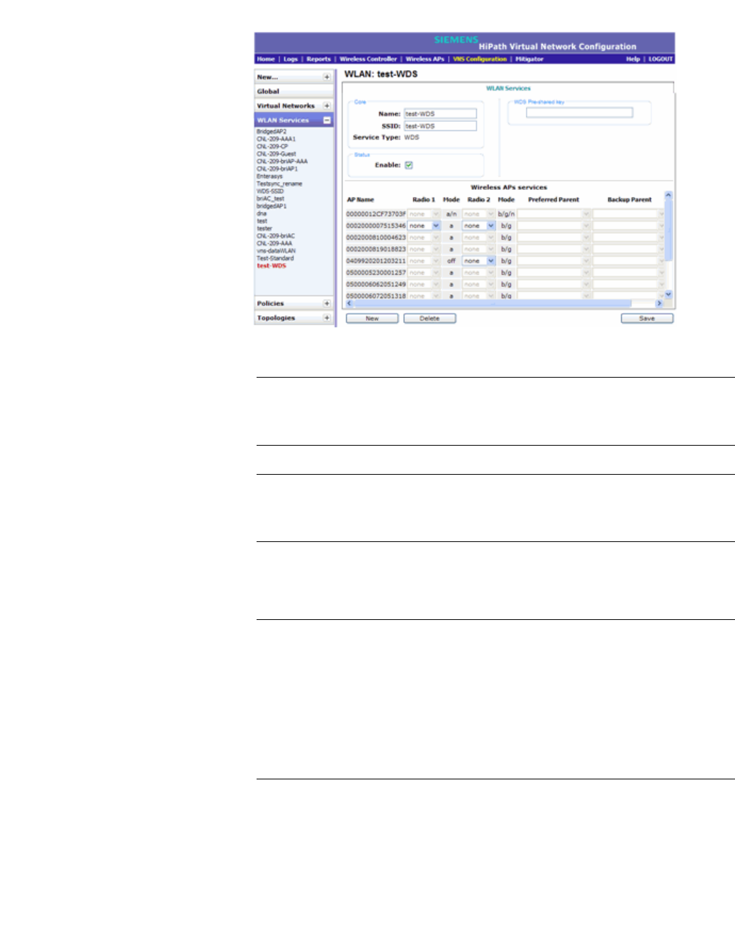
hwc_vnsconfiguration.fm
Configuring a VNS
Working with a Wireless Distribution System
9034530-02, March 2010
HiPath Wireless Controller, Access Points and Convergence Software V7.11, User Guide 375
7. In the WDS Pre-shared Key box, type the key.
Note: The pre-shared key must be 8 to 63 characters long.
The WDS Wireless APs use this pre-shared key to establish a WDS link
between them.
Note: Changing the pre-shared key after the WDS is deployed can be a
lengthy process. For more information, see Section 6.11.8, “Changing the
pre-shared key in a WDS WLAN Service”, on page 379.
8. Assign the roles, preferred parents and backup parents to the Wireless AP
Radios.
Note: The roles — parent, child, and both — are assigned to the Radios of
the Wireless APs. A Wireless AP may connect to its parent Wireless AP and
children Wireless APs on the same Radio, or on a different Radio. Similarly,
a Wireless AP can have two children operating on two different Radios.
The Radio on which the child Wireless AP operates is determined by the
parent Wireless AP.
If the Wireless AP will be serving both as parent and child, you must select
both as its role.
To configure the WDS as illustrated in Figure 23 with a single WDS VNS, you
must assign the roles, preferred parents and backup parents to the Wireless
APs according to the following table:

Configuring a VNS
hwc_vnsconfiguration.fm
Working with a Wireless Distribution System
9034530-02, March 2010
376 HiPath Wireless Controller, Access Points and Convergence Software V7.11, User Guide
Note: Since the Root Wireless APs — Ardal, Arthur, Athens and Auberon —
are the highest entities in the tree structure, they do not have parents.
Therefore, the Preferred Parent and Backup Parent drop-down lists of the
Root Wireless APs do not display any Wireless AP. You must leave these two
fields blank.
Note: You must first assign the ‘parent’ role to the Wireless APs that will serve
as the parents. Unless this is done, the Parent Wireless APs will not be
displayed in the Preferred Parent and Backup Parent drop-down lists of
other Wireless APs.
Note: The WDS Bridge feature on the user interface relates to WDS Bridge
configuration. When you are configuring the WDS Bridge topology, you must
select WDS Bridge for Satellite Wireless AP that is connected to the wired
network. For more information, see Section 6.11.3, “Wireless Bridge
configuration”, on page 364.
Wireless AP Radio b/g Radio a Preferred Parent Backup Parent
Ardal Parent Parent See the note
below.
See the note
below.
Arthur Parent Parent See the note
below.
See the note
below.
Athens Parent Parent See the note
below.
See the note
below.
Auberon Parent Parent See the note
below.
See the note
below.
Bawdy Both Child Ardal Arthur
Bern Both Child Arthur Ardal
Barend Both Child Athens Auberon
Barett Both Child Auberon Athens
Osborn Child Child Bawdy Ardal
Oscar Child Child Bern Arthur
Orson Child Child Barend Athens
Oswald Child Child Barett Auberon
Table 35 Wireless APs and their roles
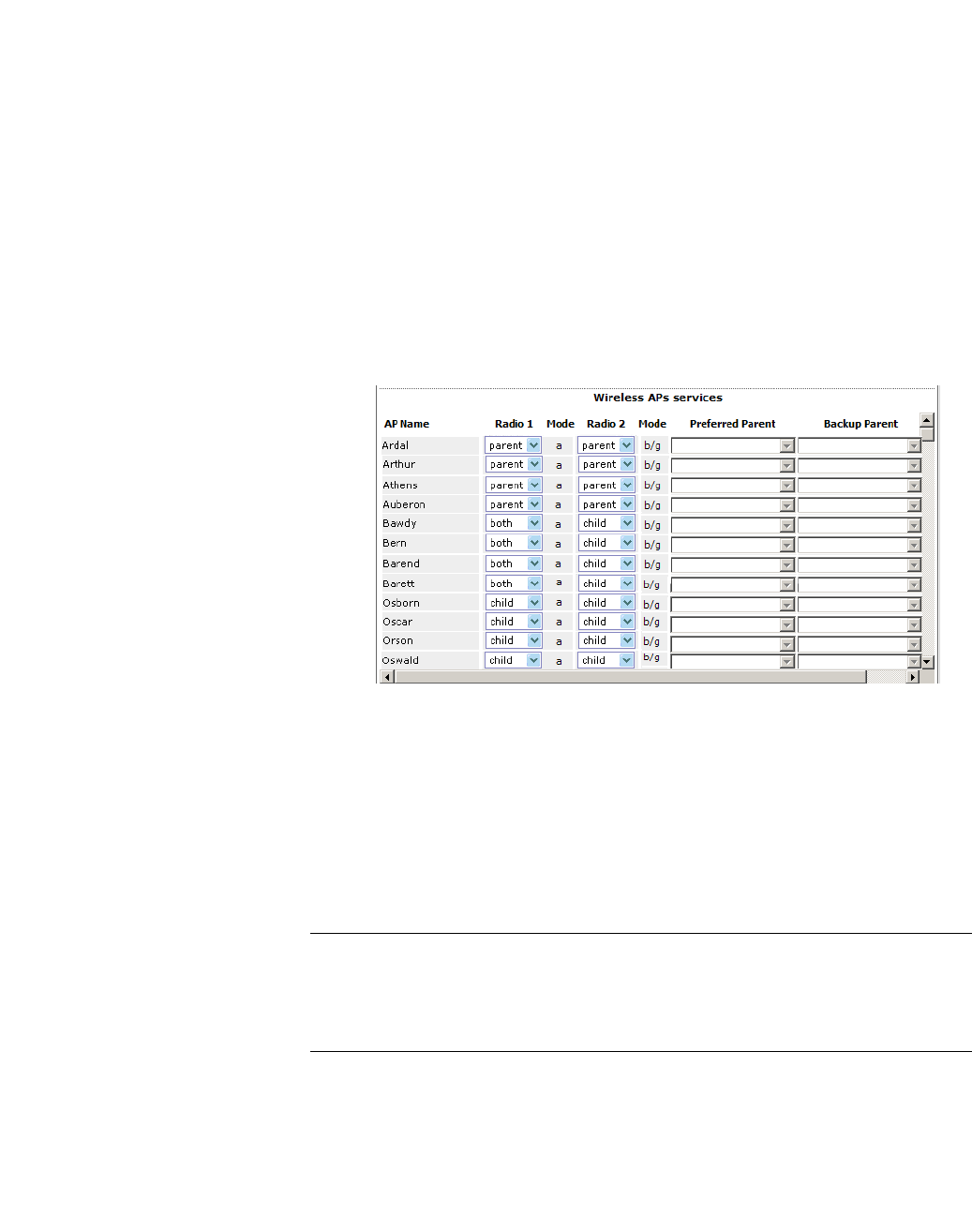
hwc_vnsconfiguration.fm
Configuring a VNS
Working with a Wireless Distribution System
9034530-02, March 2010
HiPath Wireless Controller, Access Points and Convergence Software V7.11, User Guide 377
To assign the roles, preferred parent and backup parent:
a) From the radio b/g drop-down list of the Root Wireless APs — Ardal,
Arthur, Athens and Auberon, click Parent.
b) From the radio a drop-down list of the Root Wireless APs — Ardal, Arthur,
Athens and Auberon, click Parent.
c) From the radio a and radio b/g drop-down list of other Wireless APs, click
the roles according to Table 35.
d) From the Preferred Parent drop-down list of other Wireless APs, click the
parents according to Table 35.
e) From the Backup Parent drop-down list of other Wireless APs, click the
backup parents according to Table 35.
9. To save your changes, click Save.
6.11.7.3 Assigning the Satellite Wireless APs’ radios to the
network WLAN Services
You must assign the Satellite Wireless APs’s radios to the network WLAN
Services.
Note: Network WLAN Services are the typical WLAN Services on which the
Wireless APs service the client devices: Routed, Bridge Traffic Locally at
HWC, and Bridge Traffic Locally at AP. For more information, see Section 6.2,
“VNS global settings”, on page 245.
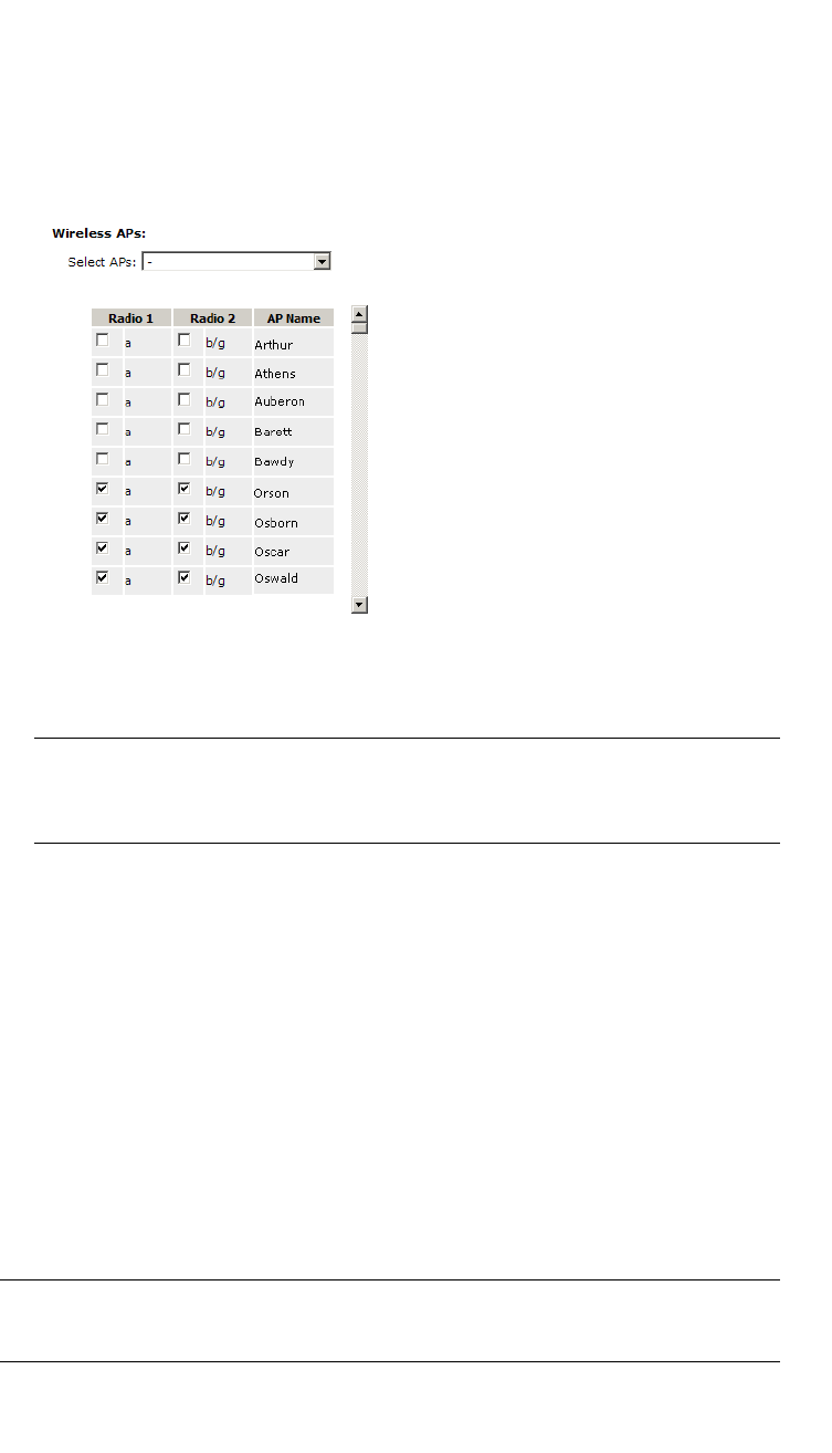
Configuring a VNS
hwc_vnsconfiguration.fm
Working with a Wireless Distribution System
9034530-02, March 2010
378 HiPath Wireless Controller, Access Points and Convergence Software V7.11, User Guide
To assign the Satellite Wireless APs’ radios to the network WLAN Service:
1. From the main menu, click Virtual Network Configuration. The Virtual
Network Configuration screen is displayed.
2. In the left pane, expand the WLAN Services pane and select a network WDS
service to edit
3. In the Wireless APs list, select the radios of the Satellite APs — Osborn,
Oscar, Orson and Oswald.
Note: If you want the Root Wireless AP and the Repeater Wireless APs to
service the client devices, you must select their radios in addition to the radios
of the Satellite Wireless APs.
4. To save your changes, click Save.
5. Log out from the HiPath Wireless Controller.
6.11.7.4 Connecting the WDS Wireless APs to the enterprise
network for provisioning
You must connect the WDS Wireless APs to the enterprise network once more in
order to enable them to obtain their configuration from the HiPath Wireless
Controller. The configuration includes the pre-shared key, the Wireless AP’s role,
preferred parent and backup parent. For more information, see Provisioning the
WDS Wireless APs on page 371.
Warning: If you skip this step, the WDS Wireless APs will not work at their target
location.

hwc_vnsconfiguration.fm
Configuring a VNS
Working with a Wireless Distribution System
9034530-02, March 2010
HiPath Wireless Controller, Access Points and Convergence Software V7.11, User Guide 379
6.11.7.5 Moving the WDS Wireless APs to the target location
1. Disconnect the WDS Wireless APs from the enterprise network, and move
them to the target location.
2. Install the WDS Wireless APs at the target location.
3. Connect the Wireless APs to a power source. The discovery and registration
processes are initiated.
Note: If you change any of the following configuration parameters of a WDS
Wireless AP, the WDS Wireless AP will reject the change:
• Reassigning the WDS Wireless AP’s role from Child to None
• Reassigning the WDS Wireless AP’s role from Both to Parent
• Changing the Preferred Parent of the WDS Wireless AP
However, the HiPath Wireless Controller will display your changes, as these
changes will be saved in the database. To enable the WDS Wireless AP to obtain
your changes, you must remove it from the WDS location and then connect it to
the HiPath Wireless Controller via the wired network.
Note: If you change any of the following radio properties of a WDS Wireless AP,
the WDS Wireless AP will reject the change:
• Disabling the radio on which the WDS link is established
• Changing the radio’s Tx Power of a radio on which the WDS link is established
• Changing the country
6.11.8 Changing the pre-shared key in a WDS WLAN
Service
To change the pre-shared key in a WDS WLAN Service
1. Create a new WDS WLAN Service with a new pre-shared key.
2. Assign the RF of the Wireless APs from the old WDS to the new WDS WLAN
Service.
3. Check the WDS Wireless AP Statistics report page to ensure that all the
WDS Wireless APs have connected to the HiPath Wireless Controller via the
new WDS VNS. For more information, see Section 11.1.2, “Viewing statistics
for Wireless APs”, on page 430.
4. Delete the old WDS WLAN Service. For more information, see Section 6.7.3,
“Deleting a VNS”, on page 296.

Configuring a VNS
hwc_vnsconfiguration.fm
Working with a Wireless Distribution System
9034530-02, March 2010
380 HiPath Wireless Controller, Access Points and Convergence Software V7.11, User Guide

hwc_fastfailover.fm
Availability and session availability
Availability
9034530-02, March 2010
HiPath Wireless Controller, Access Points and Convergence Software V7.11, User Guide 381
7 Availability and session availability
This chapter describes the availability feature, including:
•Availability
•Session availability
•Viewing the Wireless AP availability display
•Viewing SLP activity
7.1 Availability
The HiPath Wireless Controller, Access Points and Convergence Software
system provides the ‘availability’ feature to maintain service availability in the
event of a HiPath Wireless Controller outage.
The availability feature links two HiPath Wireless Controllers — the primary
controller and the secondary controller (backup controller). The primary and the
secondary controllers share information about their Wireless APs. If the primary
controller fails, its Wireless APs failover to the secondary controller. The
secondary controller provides the wireless network and pre-assigned VNSs for
the Wireless APs.
Note: During the failover event, the maximum number of failover APs the
secondary controller can accommodate is equal to the maximum number of APs
supported by the hardware platform.
Wireless APs that attempt to connect to the secondary controller during a failover
event are assigned to the WLAN Service that is defined in the system’s default
AP configuration, provided the administrator has not assigned the failover
Wireless APs to one or more VNSs. If a system default AP configuration does not
exist for the controller (and the administrator has not assigned the failover
Wireless APs to any WLAN Service), the APs will not be assigned to any WLAN
Service during the failover.
A HiPath Wireless Controller will not accept a connection by a foreign AP if the
HiPath Wireless Controller believes its availability partner controller is in service.
Also, the default Wireless AP configuration assignment is only applicable to new
APs that failover to the backup controller. Any Wireless AP that has previously
failed over and is already known to the backup system will receive the
configuration already present on that system. For more information, see Section
4.5.3, “Configuring the default Wireless AP settings”, on page 181.
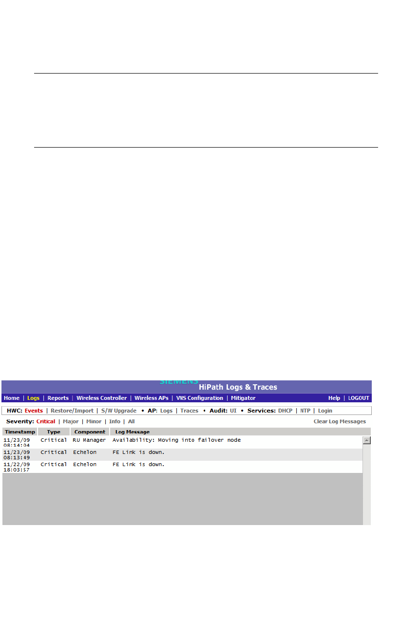
Availability and session availability
hwc_fastfailover.fm
Availability
9034530-02, March 2010
382 HiPath Wireless Controller, Access Points and Convergence Software V7.11, User Guide
During the failover event when the Wireless AP connects to the secondary
controller, the users are disassociated from the Wireless AP. Consequently, the
users must log on again and be authenticated on the secondary controller before
the wireless service is restored.
Note: If you want the mobile user’s session to be maintained, you must use the
‘session availability’ feature that enables the primary controller’s Wireless APs to
failover to the secondary controller fast enough to maintain the session
availability (user session). For more information, see Section 7.4, “Session
availability”, on page 392.
The availability feature provides Wireless APs with a list of interfaces. The
Wireless AP should attempt to connect automatically to these interfaces when the
connection with an active controller link is lost. The provided list identifies the
local active interfaces for the active controller as well as the active interfaces for
the backup controller. The list is sorted by top-down priority. If the active link is lost
(poll failure), the Wireless AP automatically scans (pings) all addresses in its
availability interface list. The Wireless AP will then connect to the highest priority
interface that responds to its probe.
7.1.1 Events and actions in availability
If one of the HiPath Wireless Controllers in a pair fails, the communication
between the two HiPath Wireless Controllers stops. This triggers a failover
condition following which a critical message is displayed in the information log of
the secondary HiPath Wireless Controller.
After a Wireless AP on the failed HiPath Wireless Controller loses its connection,
it will try to connect to all enabled interfaces on both controllers without rebooting.
If the Wireless AP is not successful, it will begin the discovery process. If the
Wireless AP is not successful in connecting to the HiPath Wireless Controller
after five minutes of attempting, the Wireless AP will reboot if there is no Bridge
traffic locally at the AP topology associated to it.

hwc_fastfailover.fm
Availability and session availability
Availability
9034530-02, March 2010
HiPath Wireless Controller, Access Points and Convergence Software V7.11, User Guide 383
All mobile user’s sessions using the failover Wireless AP will terminate except
those associated to a Bridge traffic locally at the AP and if the Maintain client
sessions in event of poll failure option is enabled on the AP Properties tab or
AP Default Settings screen.
When the Wireless APs connect to the second HiPath Wireless Controller, they
are either assigned to the VNS that is defined in the system’s default AP
configuration or manually configured by the administrator. The mobile users log
on again and are authenticated on the second HiPath Wireless Controller.
When the failed HiPath Wireless Controller recovers, each HiPath Wireless
Controller in the pair goes back to normal mode. They exchange information
including the latest lists of registered Wireless APs. The administrator must
release the Wireless APs manually on the second HiPath Wireless Controller, so
that they may re-register with their home HiPath Wireless Controller. Foreign APs
can now all be released at once by using the Foreign button on the Access
Approval screen to select all foreign APs, and then clicking Release.
To support the availability feature during a failover event, administrators need to
do the following:
1. Monitor the critical messages for the failover mode message, in the
information log of the remaining HiPath Wireless Controller (in the Logs &
Traces section of the HiPath Wireless Assistant).
2. After recovery, on the HiPath Wireless Controller that did not fail, select the
foreign Wireless APs, and then click Release on the Access Approval
screen.
7.1.2 Availability prerequisites
Before you configure availability, ensure you have completed the following:
•Choose the primary and secondary HiPath Wireless Controllers.
•Verify the network accessibility for the UDP connection between the two
controllers. The availability link is established as a UDP session on port
13911.
•Set up a DHCP server for AP subnets to support Option 78 for SLP, so that it
points to the IP addresses of the physical interfaces on both the HiPath
Wireless Controllers.
•Ensure that the Poll Timeout value on the AP Properties tab Advanced
dialog is set to 1.5 to 2 times of Detect link failure value on the HiPath
Wireless Controller > Availability screen. For more information, see
Section 4.4.2, “Configuring a Wireless AP’s properties”, on page 122.

Availability and session availability
hwc_fastfailover.fm
Configuring availability using the availability wizard
9034530-02, March 2010
384 HiPath Wireless Controller, Access Points and Convergence Software V7.11, User Guide
If the Poll Timeout value is less than 1.5 to 2 times of Detect link failure
value, the Wireless AP failover will not succeed because the secondary
controller will not be 'ready' to accept the failover APs.
On the other hand, if the Poll Timeout value is more than 1.5 to 2 times of
Detect link failure value, the Wireless APs failover will be unnecessarily
delayed, because the Wireless APs will continue polling the primary controller
even though the secondary controller is ready to accept them as the failover
APs.
•To achieve ideal 'availability' behavior, you must set the Poll Timeout value
for all Wireless APs to 15 seconds, and the Detect link failure on the HiPath
Wireless Controller > Availability screen to ten seconds.
7.2 Configuring availability using the availability wizard
The availability wizard allows you to create an availability pair from one of the
HiPath Wireless Controller’s that will take part in the availability pair. When
creating the availability pair, you also have the option to synchronize VNS
definitions and GuestPortal user accounts between the paired HiPath Wireless
Controllers.
To configure availability using the availability wizard:
1. From the main menu, click Wireless Controller Configuration. The HiPath
Wireless Controller Configuration screen is displayed.
2. In the left pane, click Availability. The availability configuration screen is
displayed.
3. In the Availability Wizard section, click Start. The Availability Pair Wizard
screen is displayed.
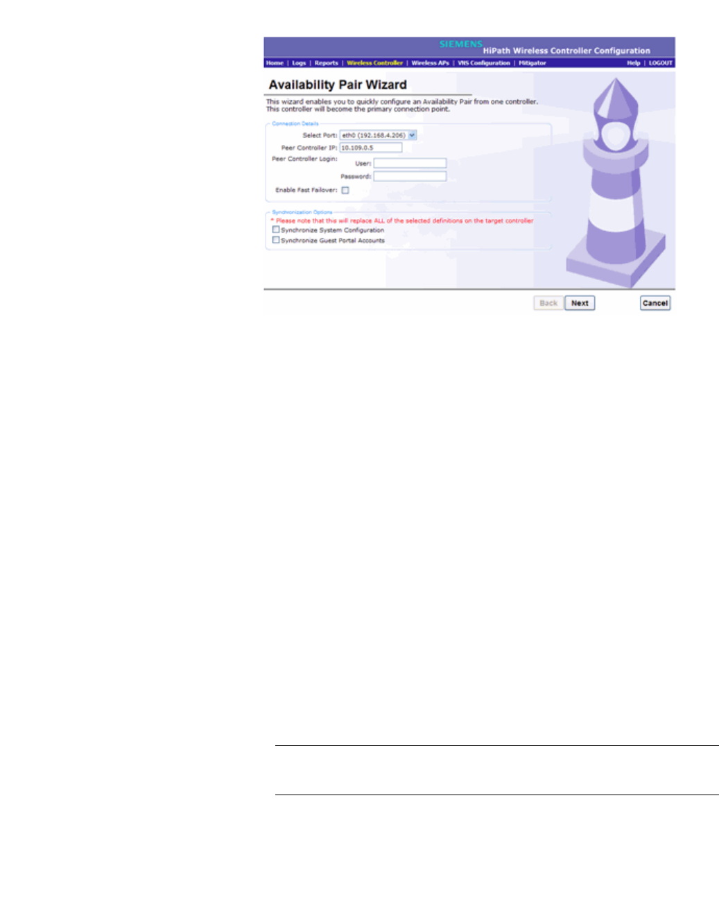
hwc_fastfailover.fm
Availability and session availability
Configuring availability using the availability wizard
9034530-02, March 2010
HiPath Wireless Controller, Access Points and Convergence Software V7.11, User Guide 385
4. In the Connection Details section, do the following:
• Select Port – Click the port and IP address of the primary controller that
is to be used to establish the availability link.
• Peer Controller IP – Type the IP address of the peer (secondary)
controller.
•User – Type the login user name credentials of an account that has full
administrative privileges on the peer controller.
• Password – Type the login password used with the user ID to login to the
peer controller.
•password used with the userid to login to the peer controller..
• Enable Fast Failover – Select this checkbox to enable Fast Failover for
the availability pair.
5. In the Synchronize Options section, do the following:
• Synchronize System Configuration – Select this checkbox to push the
configured Routed and Bridge Traffic Locally at HWC VNS definitions
from the primary controller to the peer controller. WDS and 3rd Party AP
VNS definitions are ignored and not synchronized.
Note: Synchronizing the VNS definitions will delete and replace existing
VNS definitions on the peer controller.
• Synchronize Guest Portal Accounts – Select this checkbox to push
GuestPortal user accounts to the peer controller.
6. Click Next.

Availability and session availability
hwc_fastfailover.fm
Configuring availability manually
9034530-02, March 2010
386 HiPath Wireless Controller, Access Points and Convergence Software V7.11, User Guide
•If you are synchronizing topology definitions, the Topology Definitions
screen is displayed. Do the following:
a) In the Synchronization Settings section, complete the topology
properties that are missing. Any topology that did not already exist on
the peer controller will have missing properties on the Topology
Definitions screen.
The fields configured are actual parameter values that are configured
at the remote Controller with respect to associated topologies chosen
for synchronization. Some of these parameters are: Interface IP
address, Netmask, L2 port, VLAN ID, DHCP range, etc.
b) Click Finish.
•If you are not synchronizing topology definitions, the availability wizard
completes the configuration.
7. Click Close.
This operation will mark the desired topologies as desired for synchronization.
The two controllers exchange information and the configuration is applied to the
remote controller.
On the local controller, the "Enable Synchronization of System Configuration"
becomes selected. This can be double checked by navigating to VNS
Configuration, Global and then Sync Summary. This tab also lists all Topologies,
Policies, WLAN Services and VNSes with their synchronization status (on or off).
The Sync status for any of these elements can also be changed from this tab.
Moreover, all these configurable elements have a check box called "synchronize"
(on their main/general configuration tab) that would allow for individual control
and selection of availability from the main element configuration page.
7.3 Configuring availability manually
When configuring availability manually, you configure each HiPath Wireless
Controller separately. One method is as follows:
1. On the HiPath Wireless Controller Configuration Availability screen, set up
the HiPath Wireless Controller in Paired Mode.
2. On the VNS configuration window, define a VNS (through topology, WLAN
service, policy and VNS configuration) on each HiPath Wireless Controller
with the same SSID. The IP addresses must be unique. For more information,
see Section 6.8, “Configuring a Topology”, on page 296. A HiPath Wireless
Controller VLAN Bridged topology can permit two controllers to share the
same subnet. This setup provides support for mobility users in a VLAN
Bridged VNS.

hwc_fastfailover.fm
Availability and session availability
Configuring availability manually
9034530-02, March 2010
HiPath Wireless Controller, Access Points and Convergence Software V7.11, User Guide 387
3. On both HiPath Wireless Controllers, on the Wireless AP Registration screen,
select the Security Mode Allow only approved Wireless APs to connect
option so that no more Wireless APs can register unless they are approved
by the administrator.
4. On each HiPath Wireless Controller, on the Wireless AP configuration
Access Approval screen, check the status of the Wireless APs and approve
any APs that should be connected to that controller.
System AP defaults can be used to assign a group of VNSs to the foreign
APs:
•If the APs are not yet known to the system, the AP will be initially
configured according to AP default settings. To ensure better transition in
availability, it is recommended that the AP default settings match the
desired assignment for failover APs.
•AP assignment to WLAN Services according to the AP default settings
can be overwritten by manually modifying the AP assignment. (For
example, select and assign each WLAN service that the AP should
connect to.)
•If specific foreign APs have been assigned to a WLAN service, those
specific foreign AP assignments are used.
An alternate method to setting up APs includes:
1. Add each Wireless AP manually to each HiPath Wireless Controller.
2. On the AP Properties screen, click Add Wireless AP.
3. Define the Wireless AP, and then click Add Wireless AP.
Manually defined APs will inherit the default AP configuration settings.
Caution: If two HiPath Wireless Controllers are paired and one has the Allow
All option set for Wireless AP registration, all Wireless APs will register with
that HiPath Wireless Controller.
To set the primary or secondary HiPath Wireless Controllers for availability:
1. From the main menu, click Wireless Controller Configuration. The
Wireless Controller Configuration screen is displayed.
2. In the left pane, click Availability.
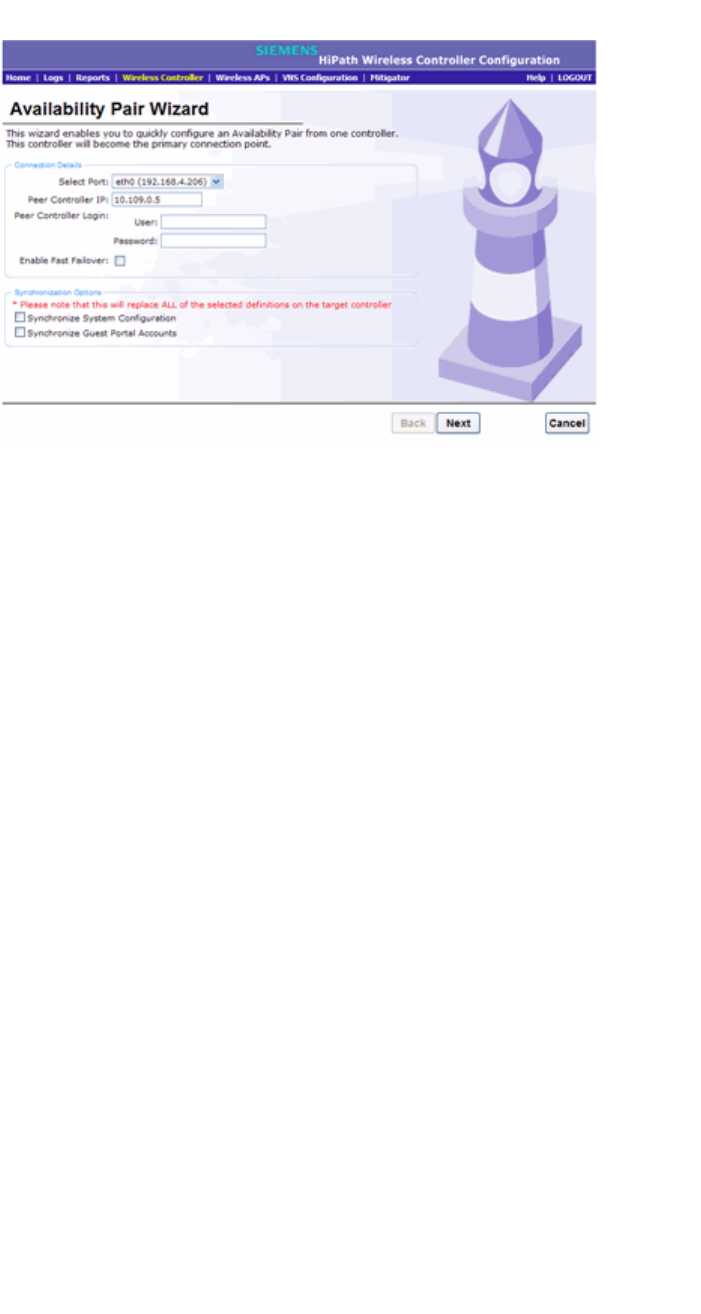
Availability and session availability
hwc_fastfailover.fm
Configuring availability manually
9034530-02, March 2010
388 HiPath Wireless Controller, Access Points and Convergence Software V7.11, User Guide
3. To enable availability, select the Paired option.
4. Do one of the following:
•For a primary controller, in the Wireless Controller IP Address box, type
the IP address of the data interface of the secondary HiPath Wireless
Controller. This IP address must be on a routable subnet between the two
HiPath Wireless Controllers.
•For a secondary controller, in the Wireless Controller IP Address box,
type the IP address of the Management port or data interface of the
primary HiPath Wireless Controller.
5. Do one of the following:
•To set this HiPath Wireless Controller as the primary connection point,
select the Current Wireless Controller is primary connect point
checkbox.
•To set this HiPath Wireless Controller as the secondary connection point,
clear the Current Wireless Controller is primary connect point
checkbox.
If the Current Wireless Controller is primary connect point checkbox is
selected, the specified controller sends a connection request. If the Current
Wireless Controller is primary connect point checkbox is cleared, the
specified controller waits for a connection request. Confirm that one controller
has this checkbox selected, and the second controller has this checkbox
cleared, since improper configuration of this option will result in incorrect
network configuration.

hwc_fastfailover.fm
Availability and session availability
Configuring availability manually
9034530-02, March 2010
HiPath Wireless Controller, Access Points and Convergence Software V7.11, User Guide 389
6. On both the primary and secondary controllers, type the Detect link failure
value.
Note: You must ensure that the Detect link failure value on both the controllers
must be identical.
7. On both the primary and secondary controllers, select the Synchronize
GuestPortal Guest Users option to synchronize GuestPortal guest accounts
between the controllers.
8. From the main menu, click Wireless AP Configuration. The HiPath
Wireless AP Configuration screen is displayed.
9. In the left pane, click AP Registration. To set the security mode for the
HiPath Wireless Controller, select one of the following options:
• Allow all Wireless APs to connect – If the HiPath Wireless Controller
does not recognize the serial number, it sends a default configuration to
the Wireless AP. Or, if the HiPath Wireless Controller recognizes the
serial number, it sends the specific configuration (port and binding key)
set for that Wireless AP.
• Allow only approved Wireless APs to connect – If the HiPath Wireless
Controller does not recognize the serial number, the Wireless APs will be
in pending mode and the administrator must manually approve them. Or,
if the HiPath Wireless Controller recognizes the serial number, it sends
the configuration for that Wireless AP.
Note: During the initial setup of the network, it is recommended to select
the Allow all Wireless APs to connect option. This option is the most
efficient way to get a large number of Wireless APs registered with the
HiPath Wireless Controller.
Once the initial setup is complete, it is recommended that the security
mode is reset to the Allow only approved Wireless APs to connect
option. This option ensures that no unapproved Wireless APs are allowed
to connect. For more information, seeSection 4.4, “Configuring Wireless
AP settings”, on page 119.
10. To save your changes, click Save.
Note: When two HiPath Wireless Controllers have been paired as described
above, each HiPath Wireless Controller's registered Wireless APs will appear
as foreign on the other controller in the list of available Wireless APs when
configuring a VNS topology.
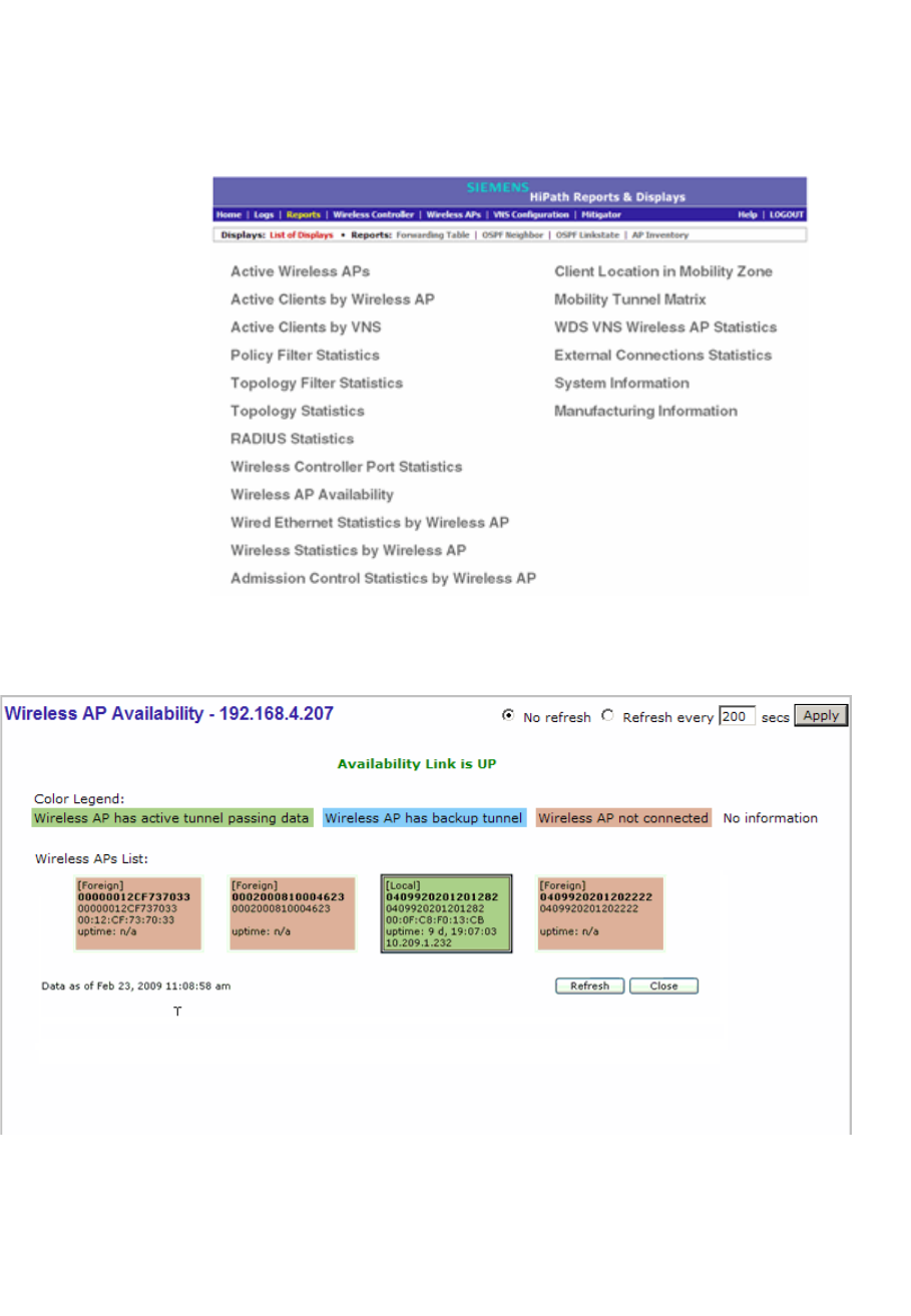
Availability and session availability
hwc_fastfailover.fm
Configuring availability manually
9034530-02, March 2010
390 HiPath Wireless Controller, Access Points and Convergence Software V7.11, User Guide
11. Verify that availability is configured correctly.
To verify that availability is configured correctly:
a) From the main menu of either of the two controllers, click Reports. The
HiPath Reports & Displays screen is displayed.
b) From the Reports and Displays menu, click Wireless AP Availability.
The Wireless Availability Report is displayed.
c) Check the statement at the top of the screen.

hwc_fastfailover.fm
Availability and session availability
Configuring availability manually
9034530-02, March 2010
HiPath Wireless Controller, Access Points and Convergence Software V7.11, User Guide 391
If the statement reads Availability link is up, the availability feature is
configured correctly. If the statement reads Availability link is down,
check the configuration error logs. For more information on logs, see the
HiPath Wireless Controller, Access Points and Convergence Software
Maintenance Guide.
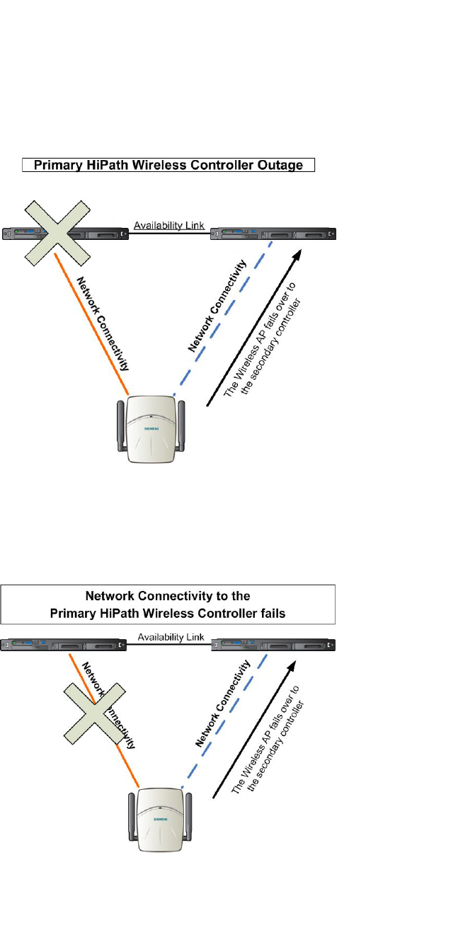
Availability and session availability
hwc_fastfailover.fm
Session availability
9034530-02, March 2010
392 HiPath Wireless Controller, Access Points and Convergence Software V7.11, User Guide
7.4 Session availability
Session availability enables Wireless APs to switch over to a standby (secondary)
HiPath Wireless Controller fast enough to maintain the mobile user’s session
availability in the following scenarios:
•The primary HiPath Wireless Controller goes down
Figure 24 The Wireless AP fails over to the secondary controller when the
primary controller goes down
•The Wireless AP’s network connectivity to the primary HiPath Wireless
Controller fails.
Figure 25 The Wireless AP fails over the secondary controller when the
network connectivity to he primary controller fails
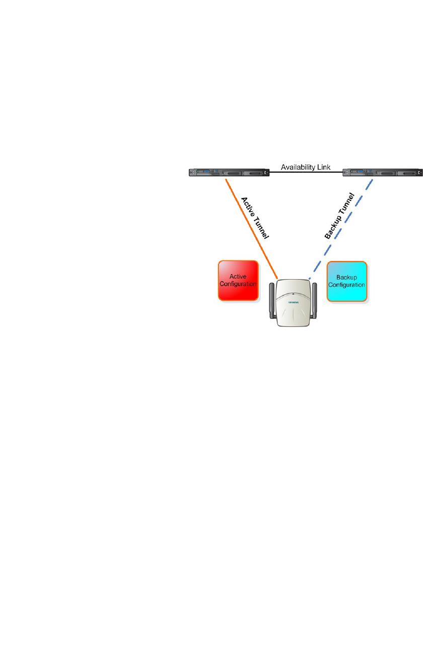
hwc_fastfailover.fm
Availability and session availability
Session availability
9034530-02, March 2010
HiPath Wireless Controller, Access Points and Convergence Software V7.11, User Guide 393
The secondary HiPath Wireless Controller does not have to detect its link failure
with the primary HiPath Wireless Controller for the session availability to kick in.
If the Wireless AP loses five consecutive polls to the primary controller either due
to the controller outage or connectivity failure, it fails over to the secondary
controller fast enough to maintain the user session.
In session availability mode, the Wireless APs connect to both the primary and
secondary HiPath Wireless Controllers. While the connectivity to the primary
HiPath Wireless Controller is via the “active” tunnel, the connectivity to the
secondary HiPath Wireless Controller is via the “backup” tunnel.
Figure 26 Session availability mode
The following is the traffic flow of the topology illustrated in Figure 26:
•The Wireless AP establishes the active tunnel to connect to the primary
HiPath Wireless Controller.
•The HiPath Wireless Controller sends the configuration to the Wireless AP.
This configuration also contains the port information of the secondary HiPath
Wireless Controller.
•On the basis of the secondary HiPath Wireless Controller’s port information,
the Wireless AP connects to the secondary controller via the backup tunnel.
•After the connection is established via the backup tunnel, the secondary
HiPath Wireless Controller sends the backup configuration to the Wireless
AP.
•The Wireless AP receives the backup configuration and stores it in its
memory to use it for failing over to the secondary controller. All this while, the
Wireless AP is connected to the primary HiPath Wireless Controller via the
‘active’ tunnel.
Primary Controller Secondary Controller
Wireless AP

Availability and session availability
hwc_fastfailover.fm
Session availability
9034530-02, March 2010
394 HiPath Wireless Controller, Access Points and Convergence Software V7.11, User Guide
Session availability and topologies
Session availability applies only to the following topologies:
•Bridge Traffic Locally at HWC
•Bridge Traffic Locally at AP
Session availability is not available to users on conventional Routed VNSs.
Note: Session availability is not supported in a VNS that is configured for AAA
network assignment.
7.4.1 Events and actions in session availability
In the event of a primary HiPath Wireless Controller outage, or the network
connectivity failure to the primary controller, the Wireless AP:
•Sends a ‘tunnel-active-req’ request message to the secondary HiPath
Wireless Controller.
•The secondary HiPath Wireless Controller accepts the request by sending
the ‘tunnel-activate-response’ message.
•The Wireless AP applies the backup configuration and starts sending the
data. The client devices’ authentication state is not preserved during failover.
When the fast failover takes place, a critical message is displayed in the
information log of the secondary HiPath Wireless Controller.
Note: In session availability, the maximum number of failover APs that the
secondary controller can accommodate is equal to the maximum number of APs
supported by the hardware platform and the license.
When the failed HiPath Wireless Controller recovers, each HiPath Wireless
Controller in the pair goes back to normal mode. They exchange information that
includes the latest lists of registered Wireless APs. The administrator must
release the Wireless APs manually on the second HiPath Wireless Controller, so
that they may re-register with their home HiPath Wireless Controller. Foreign APs
can now all be released at once by using the Foreign button on the Access
Approval screen to select all foreign APs, and then clicking Released.
To support the availability feature during a failover event, administrators need to
do the following:

hwc_fastfailover.fm
Availability and session availability
Session availability
9034530-02, March 2010
HiPath Wireless Controller, Access Points and Convergence Software V7.11, User Guide 395
1. Monitor the critical messages for the failover mode message, in the
information log of the secondary HiPath Wireless Controller (in the Logs &
Traces section of the HiPath Wireless Assistant).
2. After recovery, on the secondary HiPath Wireless Controller, select the
foreign Wireless APs, and then click Release on the Access Approval
screen.
After the Wireless APs are released, they establish the active tunnel to their home
controller and backup tunnel to the secondary controller.
7.4.2 Enabling session availability
Starting with V7.0, session availability is supported when fast failover is enabled
and when “Synchronize System Configuration” is selected. For more information,
see Section 7.4.2.1, “Configuring fast failover and enabling session availability”,
on page 395.
In session availability, mobile user devices are able to retain their IP address. In
addition, the mobile user device does not have to have to re-associate after the
failover. These characteristics ensure that the failover is achieved within 5
seconds, which is fast enough to maintain the mobile user’s session.
Note: In session availability, the fast failover is achieved within 5 seconds only if
there is at least one client device (mobile unit) associated to the Wireless AP. In
the absence of any client device, the Wireless AP takes more time to failover
since there is no need to preserve the user session.
Authentication state during failover
The authentication state is not preserved during fast failover. If a WLAN Service
requires authentication, the client device must re-authenticate. However, in such
a case, the session availability is not guaranteed because authentication may
require additional time during which the user session may be disrupted.
Session availability is not supported in a WLAN Service that uses Captive Portal
(CP) authentication.
Session availability does not support user-specific filters as these filters are not
shared between the primary and secondary HiPath Wireless Controllers.
7.4.2.1 Configuring fast failover and enabling session
availability
Before you configure the fast failover feature, you must ensure:

Availability and session availability
hwc_fastfailover.fm
Session availability
9034530-02, March 2010
396 HiPath Wireless Controller, Access Points and Convergence Software V7.11, User Guide
•The primary and secondary HiPath Wireless Controllers are properly
configured in ‘availability’ mode. For more information, see Section 7.1,
“Availability”, on page 381.
•The pair of HiPath Wireless Controllers in availability mode is formed by one
of the following combinations:
•C5110 and C5110
•C4110 and C4110
•C2400 and C2400
•C20N and C20N
•C20 and C20
•CRBT8110 and CRBT8110
•CRBT8210 and CRBT8210
•C5110 and C2400
•C2400 and C20
•C2400 and C20N
•C20N and C20
•CRBT8110 and CRBT8210
•Both the primary and secondary HiPath Wireless Controllers are running the
most recent HiPath Wireless Convergence Software releases.
•A network connection exists between the two HiPath Wireless Controllers.
•The Wireless APs are operating in ‘availability’ mode.
•The deployment is designed in such a way that the service provided by the
Wireless APs is not dependent on which HiPath Wireless Controller the APs
associate with. For example, the fast failover feature will not support the
deployment in which the two HiPath Wireless Controllers in availability mode
are connected via a WAN link.
•Both the primary and secondary HiPath Wireless Controllers have equivalent
upstream access to the servers on which they depend. For example, both the
controllers must have access to the same RADIUS and DHCP servers.
•The users (client devices) that use DHCP must obtain their addresses from a
DHCP Server that is external to the HiPath Wireless Controller.
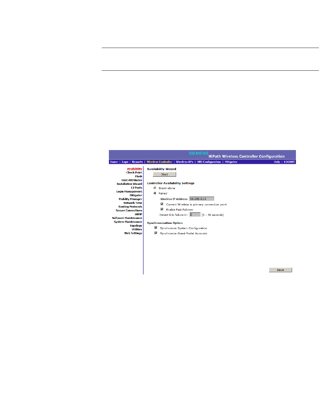
hwc_fastfailover.fm
Availability and session availability
Session availability
9034530-02, March 2010
HiPath Wireless Controller, Access Points and Convergence Software V7.11, User Guide 397
•Time on all the network elements — both the HiPath Wireless Controllers in
availability pair, Wireless APs, DHCP and RADIUS servers etc.— is
synchronized. For more information, see Section 3.4.10, “Configuring
network time”, on page 79.
Note: The fast failover feature works optimally in fast networks (preferably
switched networks).
To configure fast failover and enable session availability:
1. Log on to both the primary and secondary HiPath Wireless Controllers.
2. From the main menu of the primary HiPath Wireless Controller, click
Wireless Controller Configuration. The Wireless Controller
Configuration screen is displayed.
3. In the left pane, click Availability.
4. Under Controller Availability Settings, select Paired.
5. Select the Enable Fast Failover checkbox.
6. Type the appropriate value in the Detect link failure box.
The Detect link failure field specifies the time period within which the system
detects link failure after the link has failed. For fast failover configuration, this
parameter is tied closely to the Poll Timeout parameter on the AP
Properties tab Advanced dialog. The Poll Timeout field specifies the time
period for which the Wireless AP waits before re-attempting to establish a link
when its polling to the primary HiPath Wireless Controller fails.
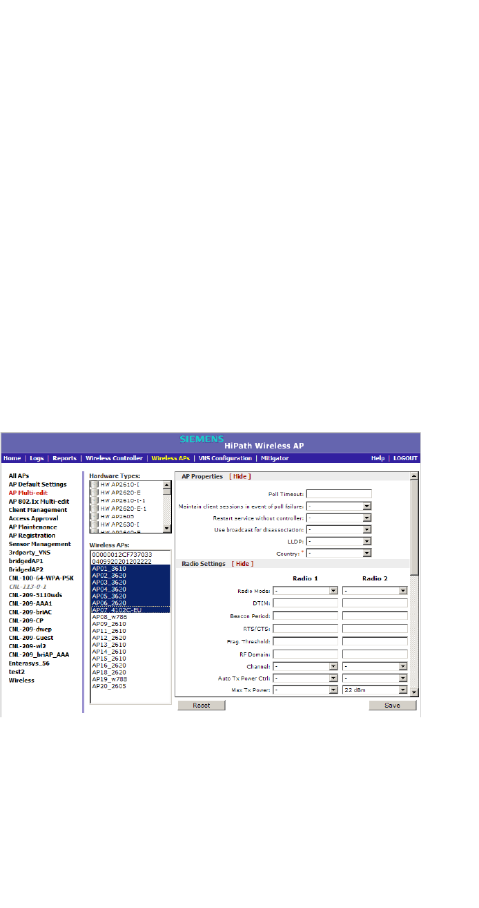
Availability and session availability
hwc_fastfailover.fm
Session availability
9034530-02, March 2010
398 HiPath Wireless Controller, Access Points and Convergence Software V7.11, User Guide
For the fast failover feature to work within the time frame of 5 seconds, the
Poll Timeout value should be 1.5 to 2 times the Detect link failure value.
For example, if you have set the Detect link failure value to 2 seconds, the
Poll Timeout value should be set to 3 or 4 seconds.
7. In the Synchronization Option area, select Synchronize System
Configuration.
This is a global parameter that enables synchronization of VNS configuration
components (Topology, Policy, WLAN Service, VNS) on both controllers
paired for availability and/or fast failover.
For more information about synchronization, see Section 6.2.7, “Using the
Sync Summary”, on page 256.
8. Click Save.
9. Set the Wireless APs’ Poll Timeout value for fast failover.
To set the Poll Timeout value for fast failover:
a) From the main menu of the primary HiPath Wireless Controller, click
Wireless AP Configuration. The AP Properties screen is displayed.
b) In the left pane, click AP Multi-edit. The AP Multi-edit screen is
displayed.
c) In the Hardware Types list, select the hardware type of the Wireless APs
that are part of your deployment. You can select multiple hardware types
by pressing the CTRL key and clicking the hardware in the Hardware
Types list.

hwc_fastfailover.fm
Availability and session availability
Session availability
9034530-02, March 2010
HiPath Wireless Controller, Access Points and Convergence Software V7.11, User Guide 399
d) In the Wireless APs list, select the Wireless APs for which you want to
set the Poll Timeout value. You can select multiple Wireless APs by
pressing the CTRL key and clicking the Wireless APs in the Wireless
APs list.
e) In the Poll Timeout box, type/edit the appropriate value.
f) To save your changes, click Save.
Note: The fast failover configuration must be identical on both the primary and
secondary HiPath Wireless Controllers. Logs are generated if the configuration is
not identical. For more information, see the HiPath Wireless Controller, Access
Points and Convergence Software Maintenance Guide.
After you have configured fast failover, you can verify session availability to
preserve the user session during the failover.
7.4.2.2 Verifying session availability
In order to have session availability, you must ensure:
•The primary and secondary HiPath Wireless Controllers are properly
configured in ‘availability’ mode. For more information, see Section 7.1,
“Availability”, on page 381.
•The fast failover feature is properly configured. For more information, see
Section 7.4.2.1, “Configuring fast failover and enabling session availability”,
on page 395.
Note: If you haven’t configured the fast failover feature, the Enable Session
Availability checkbox is not displayed.
•Time on all the network elements — both the HiPath Wireless Controllers in
availability pair, Wireless APs, DHCP and RADIUS servers etc.— is
synchronized. For more information, see Section 3.4.10, “Configuring
network time”, on page 79.
•Both the HiPath Wireless Controllers in fast failover mode must be running
the most recent HiPath Wireless Convergence Software release.
•If you are using Bridge Traffic Locally at HWC topology, you must select
None from the DHCP Option drop-down menu.
•The Bridge Traffic Locally at HWC must be mapped to the same VLAN on
both the primary and secondary HiPath Wireless Controllers.
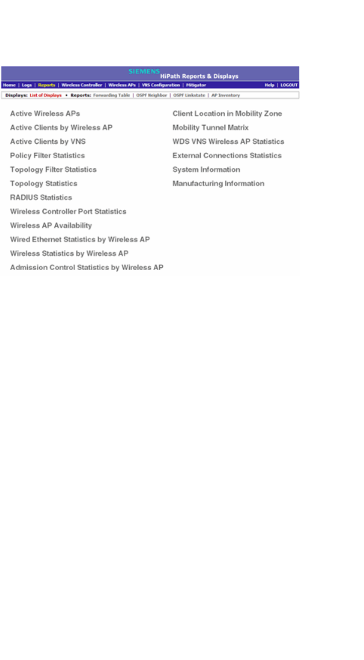
Availability and session availability
hwc_fastfailover.fm
Session availability
9034530-02, March 2010
400 HiPath Wireless Controller, Access Points and Convergence Software V7.11, User Guide
To verify the session availability feature is configured correctly:
1. From the main menu of either of the two controllers, click Reports. The
HiPath Reports & Displays screen is displayed.
2. From the Reports and Displays menu, click Wireless AP Availability. The
Wireless Availability Report is displayed.
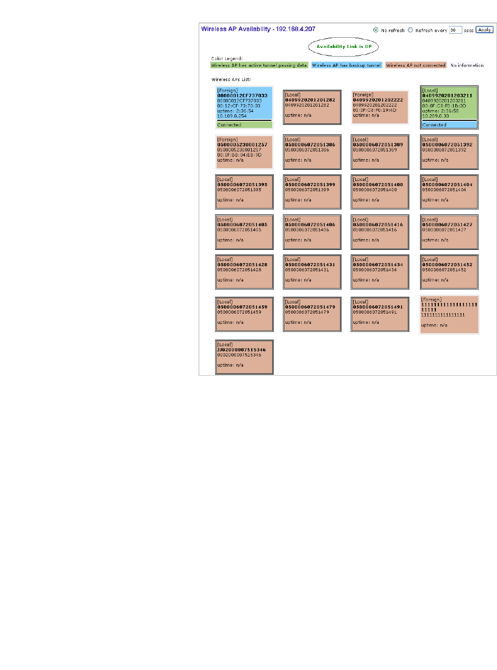
hwc_fastfailover.fm
Availability and session availability
Session availability
9034530-02, March 2010
HiPath Wireless Controller, Access Points and Convergence Software V7.11, User Guide 401
3. Check the statement at the top of the screen.
If the statement reads Availability link is up, the availability feature is
configured correctly. If the statement reads Availability link is down, check
the configuration error in logs. For more information on logs, see the HiPath
Wireless Controller, Access Points and Convergence Software Maintenance
Guide.
7.4.2.3 To verify synchronization
To verify that all elements have been synchronized correctly, navigate to the VNS
tab on both the primary and secondary HiPath Wireless Controllers, and confirm
that the topologies, WLAN services, policies and desired VNSs aredisplayed as
[synchronized].
This can be verified by selecting the apropriate tabs and then inspecting the
Synchronized flags or by navigating to VNS Configuration, Global, and then Sync
Summary page.
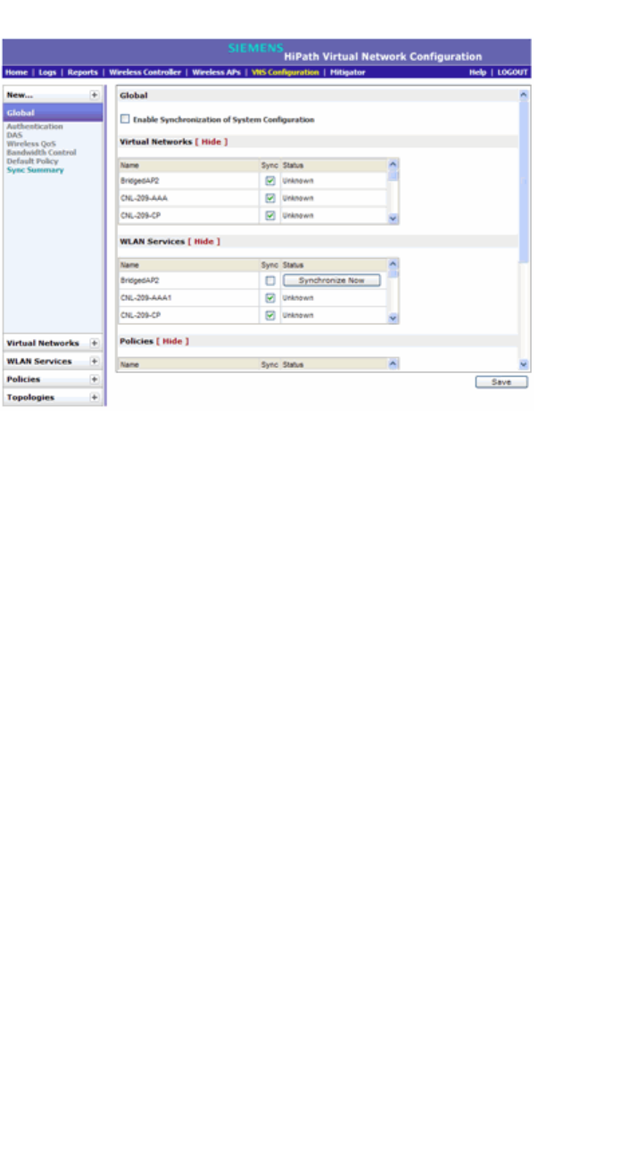
Availability and session availability
hwc_fastfailover.fm
Viewing the Wireless AP availability display
9034530-02, March 2010
402 HiPath Wireless Controller, Access Points and Convergence Software V7.11, User Guide
Configuration synchronization:
•VNS configuration related synchronization will be supported with legacy or
fast failover availability configuration as long as there is an availability link
established.
•Synchronization for VNS, WLAN Services, Policies, Topologies, and Rate
Limit Profiles can be enabled/disabled individually.
•VNS, WLAN Service, Policy, Topology, and Rate Limit Profile configuration
will be dynamically synchronized when synchronization is enabled
individually between a pair of HiPath Wireless Controllers.
MU session synchronization:
•MU session synchronization will be supported only when there is fast failover
configured between two HiPath Wireless Controllers.
•If mobility is disabled, MU session with Bridge Traffic Locally at AP, Bridge
Traffic Locally at HWC, and Routed topologies will all be synchronized
between a pair of HiPath Wireless Controllers.
•If mobility is enabled, an MU session with Routed topologies will not be
synchronized.
7.5 Viewing the Wireless AP availability display
For more information, see Section 11.1.1, “Viewing the Wireless AP availability
display”, on page 429.
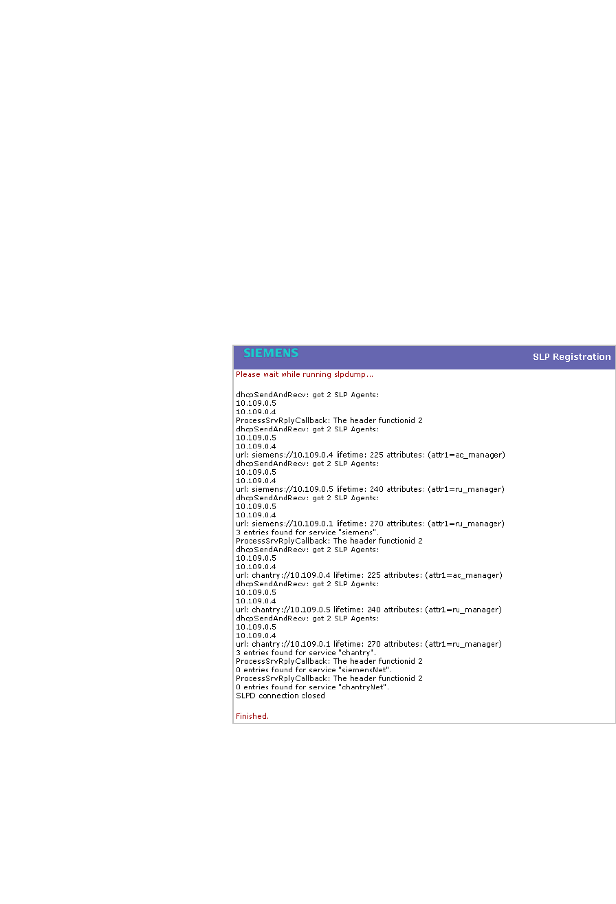
hwc_fastfailover.fm
Availability and session availability
Viewing SLP activity
9034530-02, March 2010
HiPath Wireless Controller, Access Points and Convergence Software V7.11, User Guide 403
7.6 Viewing SLP activity
In normal operations, the primary HiPath Wireless Controller registers as an SLP
service called ac_manager. The controller service directs the Wireless APs to the
appropriate HiPath Wireless Controller. During an outage, if the remaining HiPath
Wireless Controller is the secondary controller, it registers as the SLP service
ru_manager.
To view SLP activity:
1. From the main menu, click Wireless AP Configuration. The Wireless APs
screen is displayed.
2. In the left pane, click AP Registration. The Wireless AP Registration
screen is displayed.
3. To confirm SLP registration, click View SLP Registration. A pop-up screen
displays the results of the diagnostic slpdump tool, to confirm SLP
registration.

Availability and session availability
hwc_fastfailover.fm
Viewing SLP activity
9034530-02, March 2010
404 HiPath Wireless Controller, Access Points and Convergence Software V7.11, User Guide

hwc_mobility.fm
Configuring Mobility
Mobility overview
9034530-02, March 2010
HiPath Wireless Controller, Access Points and Convergence Software V7.11, User Guide 405
8 Configuring Mobility
This chapter describes the mobility concept, including:
•Mobility overview
•Mobility domain topologies
•Configuring mobility domain
8.1 Mobility overview
The HiPath Wireless Controller, Access Points and Convergence Software
system allows multiple HiPath Wireless Controllers (up to 12) on a network to
discover each other and exchange information about a client session. This
technique enables a wireless device user to roam seamlessly between different
Wireless APs on different HiPath Wireless Controllers.
The solution introduces the concept of a mobility manager; one HiPath Wireless
Controller on the network is designated as the mobility manager and all others
are designated as mobility agents.
The wireless device keeps the IP address, and the service assignments it
received from its home HiPath Wireless Controller—the HiPath Wireless
Controller that it first connected to. The WLAN Service on each HiPath Wireless
Controller must have the same SSID and RF privacy parameter settings.
You have two options for choosing the mobility manager:
•Rely on SLP with DHCP Option 78
•Define at the agent the IP address of the mobility manager. By explicitly
defining the IP address, the agent and the mobility manager are able to find
each other directly without using the SLP discovery mechanisms. Direct IP
definition is recommended in order to provide tighter control of the registration
steps for multi-domain installations.
The HiPath Wireless Controller designated as the mobility manager:
•Is explicitly identified as the manager for a specific mobility domain. Agents
will connect to this manager to establish a mobility domain.
•Defines at the agent the IP address of the mobility manager, which allows for
the bypass of SLP. Agents directly find and attempt to register with the
mobility manager.
•Uses SLP, if this method is preferred, to register itself with the SLP Directory
Agent as SiemensNet.
•Defines the registration behavior for a multi-controller mobility domain set:

Configuring Mobility
hwc_mobility.fm
Mobility overview
9034530-02, March 2010
406 HiPath Wireless Controller, Access Points and Convergence Software V7.11, User Guide
• Open mode – A new agent is automatically able to register itself with the
mobility manager and immediately becomes part of the mobility domain
• Secure mode – The mobility manager does not allow a new agent to
automatically register. Instead, the connection with the new agent is
placed in pending state until the administrator approves the new device.
•Listens for connection attempts from mobility agents.
•Establishes connections and sends a message to the mobility agent
specifying the Heartbeat interval, and the mobility manager's IP address if it
receives a connection attempt from the agent.
•Sends regular Heartbeat messages containing wireless device session
changes and agent changes to the mobility agents and waits for a returned
update message
The HiPath Wireless Controller designated as a mobility agent:
•Uses SLP or a statically configured IP address to locate the mobility manager
•Defines at the agent the IP address of the mobility manager, which allows for
the bypass of SLP. Agents directly find and attempt to register with the
mobility manager.
•Attempts to establish a TCP/IP connection with the mobility manager
•In response to the ‘heartbeat’ message, the mobility agent sends updates on
the wireless device users and the data tunnels to the mobility manager.
If a controller configured as the mobility manager is lost, the following occurs:
•Agent to agent connections will remain active.
•Mobility agents will continue to operate based on the mobility information last
coordinated before the manager link was lost. The mobility location list
remains relatively unaffected by the controller failure. Only entries associated
with the failed controller are cleared from the registration list, and users that
have roamed from the manager controller to other agents are terminated and
required to re-register as local users with the agent where they are currently
located.
•The data link between active controllers remains active after the loss of a
mobility manager
•Mobility agents continue to use the last set of mobility location lists to service
known users
•Existing users:
•Existing users remain in the mobility scenario, and if the users are known
to the mobility domain, they continue to be able to roam between
connected controllers

hwc_mobility.fm
Configuring Mobility
Mobility domain topologies
9034530-02, March 2010
HiPath Wireless Controller, Access Points and Convergence Software V7.11, User Guide 407
•New users:
•New users become local at attaching controller
•Roaming to another controller resets session
The mobility network that includes all the HiPath Wireless Controllers and the
Wireless APs is called the Mobility Domain.
Note: The mobility feature is not backward compatible. This means that all the
HiPath Wireless Controllers in the mobility domain must be running the most
recent HiPath Wireless Convergence Software release.
8.2 Mobility domain topologies
You can configure a mobility domain in the following scenarios:
•Mobility domain without any availability
•Mobility domain with availability
•Mobility domain with session availability
Note: If you are configuring mobility, you must synchronize time on all the HiPath
Wireless Controllers that are part of the mobility domain. For more information,
see Section 3.4.10, “Configuring network time”, on page 79.
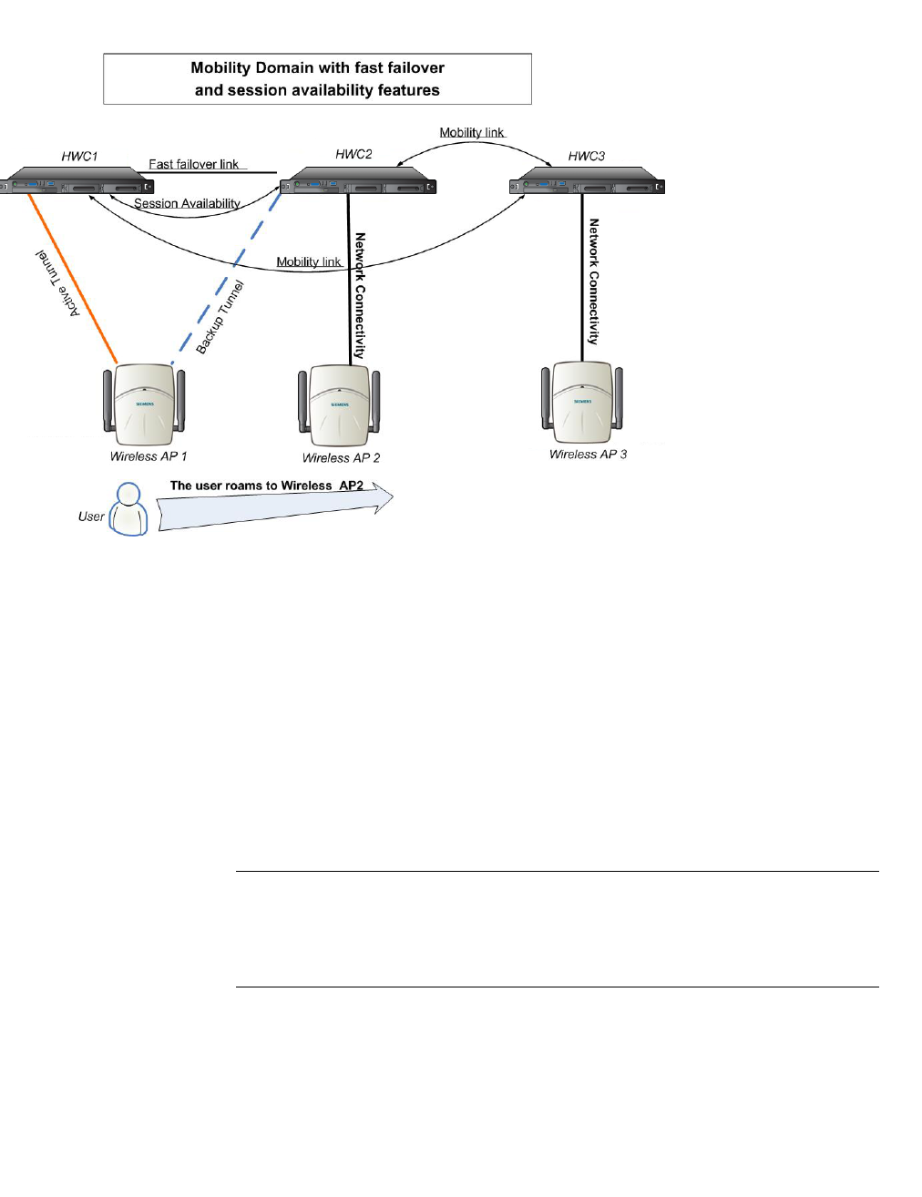
Configuring Mobility
hwc_mobility.fm
Mobility domain topologies
9034530-02, March 2010
408 HiPath Wireless Controller, Access Points and Convergence Software V7.11, User Guide
Figure 27 Mobility Domain with fast failover and session availability features
•The user’s home session is with HWC1.
•When the user roams from Wireless AP 1 to Wireless AP 2, he establishes
his home session with HWC2.
•When the user roams, the Wireless AP 1 receives a notification that the user
has roamed away following which it marks the user session as “inactive”.
Consequently, no statistics are sent to the HWC1 for that user.
•In response to the heart beat message from the mobility manager (HWC3),
the HWC2 sends updates that the user has a new home on HWC2. Upon
receiving the updates, the mobility manager updates its own tables.
Note: The mobility manager’s heart beat time is configurable. If you are
configuring a mobility domain with session availability, you should configure the
heart beat time as one second in order to enable the mobility manager to update
its tables quickly.
•If a failover takes place, and the user is still associated with Wireless AP1:
•The Wireless AP 1 fails over, and establishes an active session with
HWC2.
• HWC1 and HWC2
are configured for
session availability.
• HWC1, HWC2,
HWC3, Wireless
AP1, Wireless AP2
and Wireless AP3
form a Mobility
Domain
• HWC3 is the
Mobility Manager
whereas HWC1 and
HWC2 are Mobility
Agents
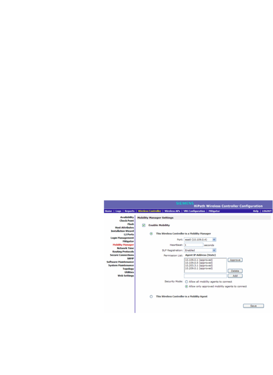
hwc_mobility.fm
Configuring Mobility
Configuring mobility domain
9034530-02, March 2010
HiPath Wireless Controller, Access Points and Convergence Software V7.11, User Guide 409
•In response to the heart beat message from the mobility manager
(HWC3), the HWC2 sends updates to the mobility manager on the
failover Wireless AP and its user.
•If a failover takes place, and the user has roamed to Wireless AP 2:
•As part of roaming, the user’s home session moves from HWC1 to
HWC2.
•Wireless AP 1 establishes active session with HWC 2. Wireless AP 2 is
not impacted by the failover.
8.3 Configuring mobility domain
If you are configuring a mobility domain with availability or session availability, you
must synchronize time on all the HiPath Wireless Controllers that are part of your
mobility domain. For more information, see Section 3.4.10, “Configuring network
time”, on page 79.
To designate a mobility manager:
1. From the main menu, click Wireless Controller Configuration. The
Wireless Controller Configuration screen is displayed.
2. In the left pane, click Mobility Manager. The Mobility Manager Settings
screen is displayed.
3. To enable mobility for this controller, select the Enable Mobility checkbox.
The controller mobility options are displayed.
4. Select the This Wireless Controller is a Mobility Manager option. The
mobility manager options are displayed.

Configuring Mobility
hwc_mobility.fm
Configuring mobility domain
9034530-02, March 2010
410 HiPath Wireless Controller, Access Points and Convergence Software V7.11, User Guide
5. In the Port drop-down list, click the interface on the HiPath Wireless
Controller to be used for the mobility manager process. Ensure that the
selected interface’s IP address is routable on the network.
6. In the Heartbeat box, type the time interval (in seconds) at which the mobility
manager sends a Heartbeat message to a mobility agent.
Note: If the mobility domain is configured for fast failover and session availability,
you should configure the mobility manager’s heart beat time as one second.
7. In the SLP Registration drop-down list, click whether to enable or disable
SLP registration.
8. In the Permission list, click the agent IP addresses you want to approve that
are in pending state, by selecting the agent and clicking Approve. New
agents are only added to the domain if they are approved.
You can also add or delete controllers that you want to be part of the mobility
domain. To add a controller, type the agent IP address in the box, and then
click Add. To delete a controller, click the controller in the list, and then click
Delete.
9. Select the Security Mode option:
• Allow all mobility agents to connect – All mobility agents can connect
to the mobility manager.
• Allow only approved mobility agents to connect – Only approved
mobility agents can connect to the mobility manager.
10. To save your changes, click Save.
Note: If you set up one HiPath Wireless Controller on the network as a mobility
manager, all other HiPath Wireless Controllers must be set up as mobility agents.
To designate a mobility agent:
1. From the main menu, click Wireless Controller Configuration. The
Wireless Controller Configuration screen is displayed.
2. In the left pane, click Mobility Manager. The Mobility Manager Settings
screen is displayed.
3. To enable mobility for this controller, select the Enable Mobility checkbox.
The controller mobility options are displayed,
4. Select the This Wireless Controller is a Mobility Agent option. The mobility
agent options are displayed.

hwc_mobility.fm
Configuring Mobility
Configuring mobility domain
9034530-02, March 2010
HiPath Wireless Controller, Access Points and Convergence Software V7.11, User Guide 411
5. From the Port drop-down list, click the port on the HiPath Wireless Controller
to be used for the mobility agent process. Ensure that the port selected is
routable on the network.
6. From the Discovery Method drop-down list, click one of the following:
•SLPD – Service Location Protocol Daemon is a background process
acting as a SLP server. It provides the functionality of the Directory Agent
and Service Agent for SLP. Use SLP to support the discovery of
siemensNET service to attempt to locate the area mobility manager
controller.
• Static Configuration – Select Static Configuration if you want to enter
the IP address of the mobility manager manually. Defining a static
configuration for a mobility manager IP address bypasses SLP discovery.
•In the Mobility Manager Address box, type the IP address for the
designated mobility manager.
7. To save your changes, click Save.
For information about viewing mobility manager displays, see Section 11.1.4,
“Viewing displays for the mobility manager”, on page 437.

Configuring Mobility
hwc_mobility.fm
Configuring mobility domain
9034530-02, March 2010
412 HiPath Wireless Controller, Access Points and Convergence Software V7.11, User Guide

hwc_3rdpartyaps.fm
9034530-02, March 2010
HiPath Wireless Controller, Access Points and Convergence Software V7.11, User Guide 413
Working with third-party APs
9 Working with third-party APs
You can set up the HiPath Wireless Controller to handle wireless device traffic
from third-party access points, while still providing policy and network access
control. This process requires the following steps:
•Define a physical Topology to operate in 3rd Party mode.
•Define a WLAN Service of type Third Party AP.
•Define a Policy.
•Define a VNS
Define authentication by Captive Portal for the third-party AP WLAN
Service:
802.1x Authentication is not supported directly by the HiPath Wireless Controller.
However, this type of authentication can be supported by the actual third-party
AP. All other options for authentication are supported at the controller.
1. On the WLAN configuration window for the third-party WLAN Service, click
the Auth & Acct tab.
2. In the Authentication Mode drop-down list, click Internal or External, then
click the Configure button.
3. Define the Captive Portal configuration as described in Section 6.9.3.7,
“Configuring Captive Portal for internal or external authentication”, on page
331.
Define the 3rd Party APs list
1. In the WLAN Services panel, select the third-party WLAN Service.
2. In the IP Address field, type the IP address of a third-party AP.
3. In the Wired MAC Address field, type the MAC address of the AP.
4. Click the Add button to add the AP to the list.
5. Repeat for all third-party APs to be assigned to this WLAN Service.
Define filtering rules for the third-party APs:
1. Because the third-party APs are mapped to a physical port, you must define
the Exception filters on the physical topology, using the Exception Filters
tab. For more information, see Section 6.8.3, “Exception filtering”, on page
304.
2. Define filtering rules that allow access to other services and protocols on the
network such as HTTP, FTP, telnet, SNMP.

Working with third-party APs
hwc_3rdpartyaps.fm
9034530-02, March 2010
414 HiPath Wireless Controller, Access Points and Convergence Software V7.11, User Guide
3. On the Multicast Filters tab, select Enable Multicast Support and configure
the multicast groups whose traffic is allowed to be forwarded to and from the
VNS using this topology. For more information, see Section 6.8.4, “Multicast
filtering”, on page 307.
In addition, modify the following functions on the third-party access point:
•Disable the access point's DHCP server, so that the IP address assignment
for any wireless device on the AP is from the DHCP server at the HiPath
Wireless Controller with VNS information.
•Disable the third-party access point's layer-3 IP routing capability and set the
access point to work as a layer-2 bridge.
The following are the differences between third-party access points and Wireless
APs on the HiPath Wireless Controller, Access Points and Convergence
Software system:
•A third-party access point exchanges data with the HiPath Wireless
Controller's data port using standard IP over Ethernet protocol. The third-
party access points do not support the tunnelling protocol for encapsulation.
•For third-party access points, the VNS is mapped to the physical data port
and this is the default gateway for mobile units supported by the third-party
access points.
•A HiPath Wireless Controller cannot directly control or manage the
configuration of a third-party access point.
•Third-party access points are required to broadcast an SSID unique to their
segment. This SSID cannot be used by any other VNS.
•Roaming from third-party access points to Wireless APs and vice versa is not
supported.

hwc_mitigator.fm
9034530-02, March 2010
HiPath Wireless Controller, Access Points and Convergence Software V7.11, User Guide 415
Working with the Mitigator
Mitigator overview
10 Working with the Mitigator
This chapter describes Mitigator concepts, including:
•Mitigator overview
•Enabling the Analysis and data collector engines
•Running Mitigator scans
•Analysis engine overview
•Working with Mitigator scan results
•Working with friendly APs
•Maintaining the Mitigator list of APs
•Viewing the Scanner Status report
10.1 Mitigator overview
The Mitigator is a mechanism that assists in the detection of rogue APs. Mitigator
functionality does the following:
Wireless AP:
•Runs a radio frequency (RF) scanning task.
•Alternating between scan functions, providing its regular service to the
wireless devices on the network.
Note: If a Wireless AP is part of a WDS link you cannot configure it to act as a
scanner in Mitigator.
HiPath Wireless Controller:
•Runs a data collector application that receives and manages the RF scan
messages sent by the Wireless AP. RF data collector data includes lists of all
connected Wireless APs, third-party APs, and the RF scan information that
has been collected from the Wireless APs selected to perform the scan.
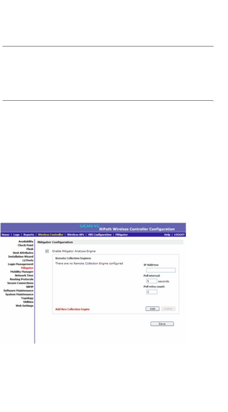
Working with the Mitigator
hwc_mitigator.fm
Enabling the Analysis and data collector engines
9034530-02, March 2010
416 HiPath Wireless Controller, Access Points and Convergence Software V7.11, User Guide
•Runs an Analysis Engine that processes the scan data from the data collector
through algorithms that make decisions about whether any of the detected
APs or clients are rogue APs or are running in an unsecure environment (for
example, ad-hoc mode).
Note: In a network with more than one HiPath Wireless Controller, it is not
necessary for the data collector to be running on the same controller as the
Analysis Engine. One controller can be a dedicated Analysis Engine while the
other controllers run data collector functionality. No more than one Analysis
Engine can be running at a time. You must ensure that the controllers are all
routable.
10.2 Enabling the Analysis and data collector engines
Before using the Mitigator, you must enable and define the Analysis and data
collector engines.
To enable the Analysis engine:
1. From the main menu, click Wireless Controller Configuration. The
Wireless Controller Configuration screen is displayed.
2. In the left pane, click Mitigator. The Mitigator Configuration screen is
displayed.
3. To enable the Mitigator Analysis Engine, select the Enable Mitigator
Analysis Engine checkbox.

hwc_mitigator.fm
Working with the Mitigator
Running Mitigator scans
9034530-02, March 2010
HiPath Wireless Controller, Access Points and Convergence Software V7.11, User Guide 417
4. To identify the remote RF Data Collector Engine that the Analysis Engine will
poll for data, type the IP address of the HiPath Wireless Controller on which
the remote Data Collector resides in the IP Address box.
Note: Currently, the HiPath Wireless Controller C20N/C20 does not support
the Remote Collection Engines functionality of the HiPath Wireless Controller,
Access Points and Convergence Software solution.
5. For the data collection engine:
•In the Poll interval box, type (in seconds) the interval that the Analysis
Engine will poll the RF Data Collector to maintain connection status. The
default is 30 seconds.
•In the Poll retry count box, type the number of times the Analysis Engine
will attempt to poll the RF Data Collector to maintain connection status,
before it stops sending requests. The default is 2 attempts.
6. Click Add. The IP address of the Data Collection Engine, with its Poll Interval
and Poll Retry parameters is displayed in the list.
Note: For each remote RF Data Collection Engine defined here, you must:
• Enable it by selecting the Enable Mitigator Analysis Engine checkbox on
the remote HiPath Wireless Controller
• Ensure that the controllers are routable by whatever means you use (for
example, static routes, or OSPF).
7. To add a new collection engine, click Add Collection Engine.
8. Repeat steps 4 to 7.
9. To save your changes, click Apply.
10.3 Running Mitigator scans
The Mitigator feature allows you to view the following:
•Scan Groups
•Friendly APs
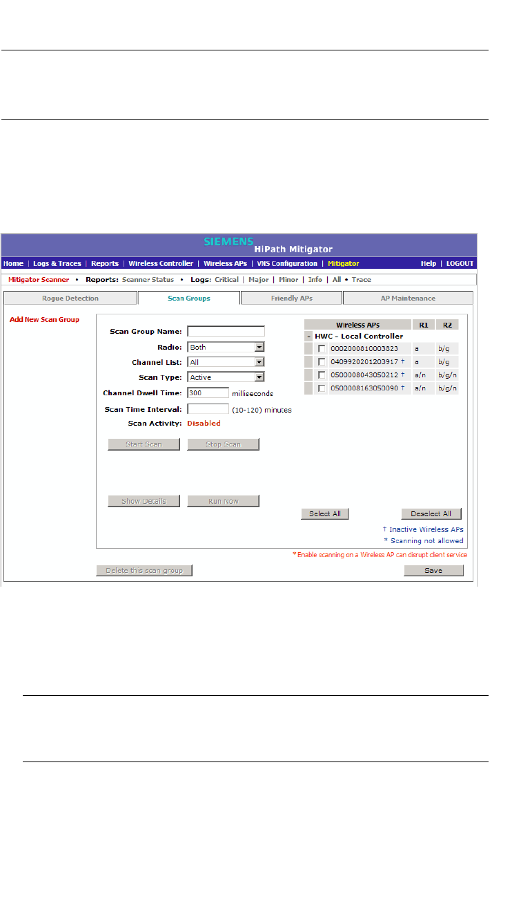
Working with the Mitigator
hwc_mitigator.fm
Running Mitigator scans
9034530-02, March 2010
418 HiPath Wireless Controller, Access Points and Convergence Software V7.11, User Guide
•AP Maintenance
Note: A scan will not run on an inactive AP, even though it is displayed as part of
the Scan Group. If it becomes active, it will be sent a scan request during the next
periodic scan.
To run the Mitigator scan task mechanism:
1. From the main menu, click Mitigator. The Mitigator screen is displayed.
2. Click the Scan Groups tab.
3. In the Scan Group Name box, type a unique name for this scan group.
4. In the Wireless APs list, select the checkbox corresponding to the Wireless
APs you want included in the new scan group, which will perform the scan
function.
Note: A Wireless AP can participate in only one Scan Group at a time. It is
recommended that the Scan Groups represent geographical groupings of
Wireless APs.
5. In the Radio drop-down list, click one of the following:
•Both – Radio 1 and Radio 2 both perform the scan function.
• radio 1 – Only Radio 1 performs the scan function.

hwc_mitigator.fm
Working with the Mitigator
Running Mitigator scans
9034530-02, March 2010
HiPath Wireless Controller, Access Points and Convergence Software V7.11, User Guide 419
• radio 2 – Only Radio 2 performs the scan function.
6. In the Channel List drop-down list, click one of the following:
•All – Scanning is performed on all channels.
• Current – Scanning is performed on only the current channel.
7. In the Scan Type drop-down list, click one of the following:
•Active – The Wireless AP sends out ProbeRequests and waits for
ProbeResponse messages from any access points.
• Passive – The Wireless AP listens for 802.11 beacons.
8. In the Channel Dwell Time box, type the time (in milliseconds) for the
scanner to wait for a response from either 802.11 beacons in passive
scanning, or ProbeResponse in active scanning.
9. In the Scan Time Interval box, type the time (in minutes) to define the
frequency at which a Wireless AP within the Scan Group will initiate a scan of
the RF space. The range is from one minute to 120 minutes.
10. To initiate a scan using the periodic scanning parameters defined above, click
Start Scan.
11. To initiate an immediate scan that will run only once, click Run Now.
Note: If necessary, you can stop a scan by clicking Stop Scan.
A scan must be stopped before modifying any parameters of the Scan Group,
or before adding or removing a Wireless AP from a Scan Group.
The Scan Activity box displays the current state of the scan engine.
12. To view a pop-up report displaying the timeline of scan activity and scan
results, click Show Details.
13. To save your changes, click Save.

Working with the Mitigator
hwc_mitigator.fm
Analysis engine overview
9034530-02, March 2010
420 HiPath Wireless Controller, Access Points and Convergence Software V7.11, User Guide
10.4 Analysis engine overview
The Analysis engine relies on a database of known devices on the Controller,
Access Points and Convergence Software system. The Analysis engine
compares the data from the RF Data Collector with the database of known
devices.
This database includes the following:
• Wireless APs – Registered with any HiPath Wireless Controller with its RF
Data Collector enabled and associated with the Analysis Engine on this
HiPath Wireless Controller.
•Third-party APs – Defined and assigned to a VNS.
• Friendly APs – A list created in the Mitigator user interface as potential rogue
access points are designated by the administrator as Friendly.
• Wireless devices – Registered with any HiPath Wireless Controller that has
its RF Data Collector enabled and has been associated with the Analysis
Engine on this HiPath Wireless Controller.
The Analysis Engine looks for access points with one or more of the following
conditions:
• Unknown MAC address and unknown SSID (critical alarm)
• Unknown MAC, with a valid SSID - a known SSID is being broadcast by the
unknown access point (critical alarm)
• Known MAC, with an unknown SSID - a rogue may be spoofing a MAC
address (critical alarm)
• Inactive Wireless AP with valid SSID (critical alarm)
• Inactive Wireless AP with unknown SSID (critical alarm)
• Known Wireless AP with an unknown SSID (major alarm)
• In ad-hoc mode (major alarm)
Note: In the current release, there is no capability to initiate a DoS attack on
the detected rogue access point. Containment of a detected rogue requires
an inspection of the geographical location of its Scan Group area, where its
RF activity has been found.
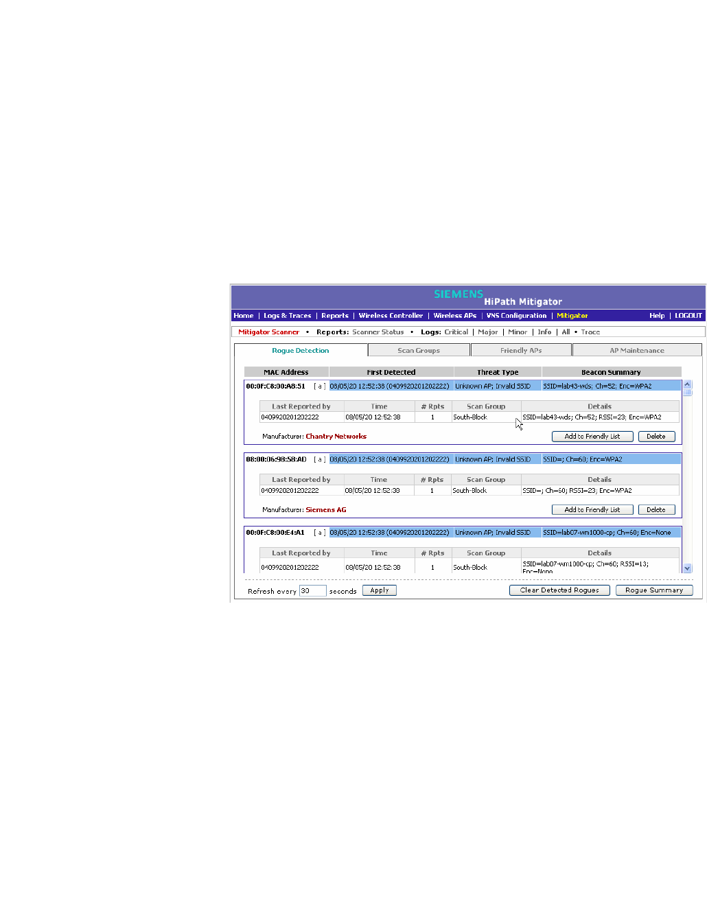
hwc_mitigator.fm
Working with the Mitigator
Working with Mitigator scan results
9034530-02, March 2010
HiPath Wireless Controller, Access Points and Convergence Software V7.11, User Guide 421
10.5 Working with Mitigator scan results
When viewing the Mitigator scan results, you can delete individual or all of the
access points from the scan results. You can also add access points from the
scan results to the Friendly AP list.
To view Mitigator scan results:
1. From the main menu, click Mitigator. The Mitigator screen is displayed.
2. Click the Rogue Detection tab.
3. To modify the page’s refresh rate, type a time (in seconds) in the Refresh
every __ seconds box.
4. Click Apply. The new refresh rate is applied.
5. To view the Rogue Summary report, click Rogue Summary. The Rogue
Summary report is displayed in a pop-up window.
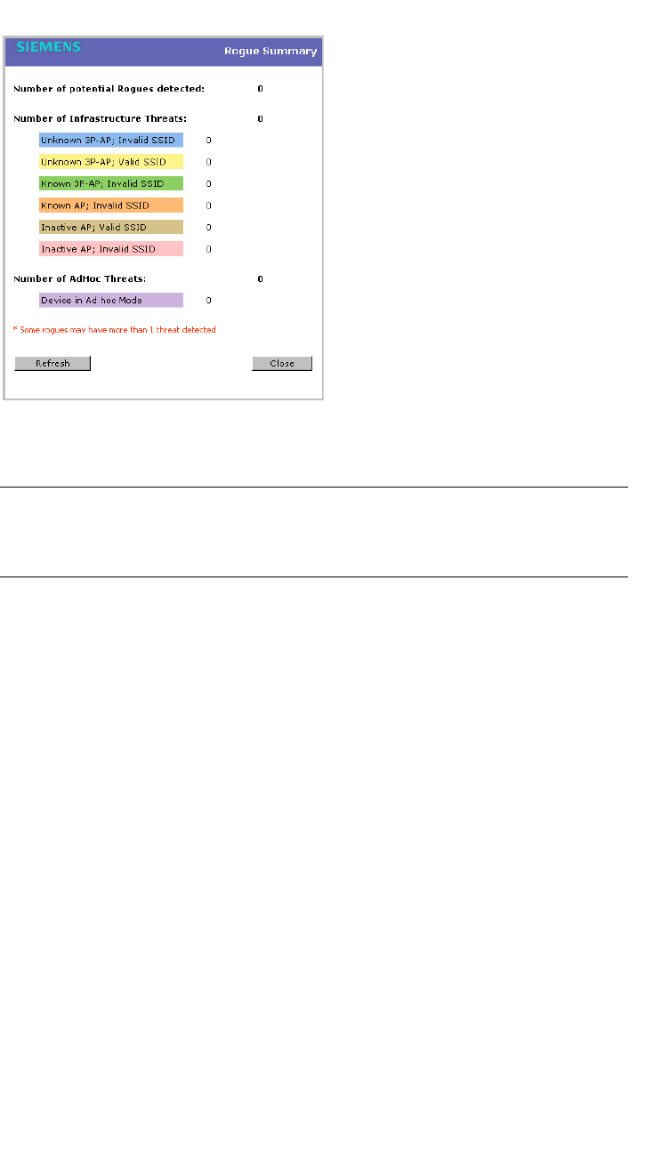
Working with the Mitigator
hwc_mitigator.fm
Working with Mitigator scan results
9034530-02, March 2010
422 HiPath Wireless Controller, Access Points and Convergence Software V7.11, User Guide
6. To clear all detected rogue devices from the list, click Clear Detected
Rogues.
Note: To avoid the Mitigator's database becoming too large, it is recommended
that you either delete Rogue APs or add them to the Friendly APs list, rather than
leaving them in the Rogue list.
To add an AP from the Mitigator scan results to the list of friendly APs:
1. From the main menu, click Mitigator. The Mitigator screen is displayed.
2. Click the Rogue Detection tab.
3. To add a Wireless AP to the Friendly APs list, click Add to Friendly List.
The AP is removed from this list and is displayed in the Friendly AP
Definitions section of the Friendly AP’s tab.
To delete an AP from the Mitigator scan results:
1. From the main menu, click Mitigator. The Mitigator screen is displayed.
2. Click the Rogue Detection tab.
3. To delete a specific AP from the Mitigator scan results, click the
corresponding Delete button. The AP is removed from the list.
4. To clear all rogue access points from the Mitigator scan results, click Clear
Detected Rogues. All APs are removed from the list.
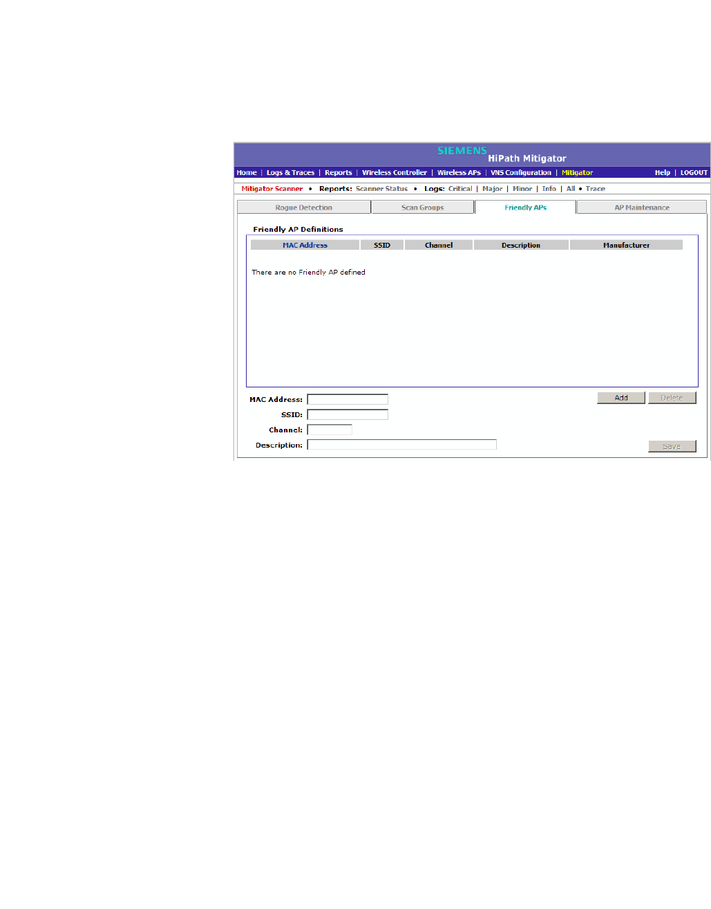
hwc_mitigator.fm
Working with the Mitigator
Working with friendly APs
9034530-02, March 2010
HiPath Wireless Controller, Access Points and Convergence Software V7.11, User Guide 423
10.6 Working with friendly APs
To view the friendly APs:
1. From the main menu, click Mitigator. The Mitigator screen is displayed.
2. Click the Friendly APs tab.
To add friendly APs manually:
1. From the main menu, click Mitigator. The Mitigator screen is displayed.
2. Click the Friendly APs tab.
3. To add friendly access points manually to the Friendly AP Definitions list,
type the following:
• MAC Address – Specifies the MAC address for the friendly AP
• SSID – Specifies the SSID for the friendly AP
• Channel – Specifies the current operating channel for the friendly AP
• Description – Specifies a brief description for the friendly AP
4. Click Add. The new access point is displayed in the list above.
To delete a friendly AP:
1. From the main menu, click Mitigator. The Mitigator screen is displayed.
2. Click the Friendly APs tab.
3. In the Friendly AP Definitions list, click the access point you want to delete.
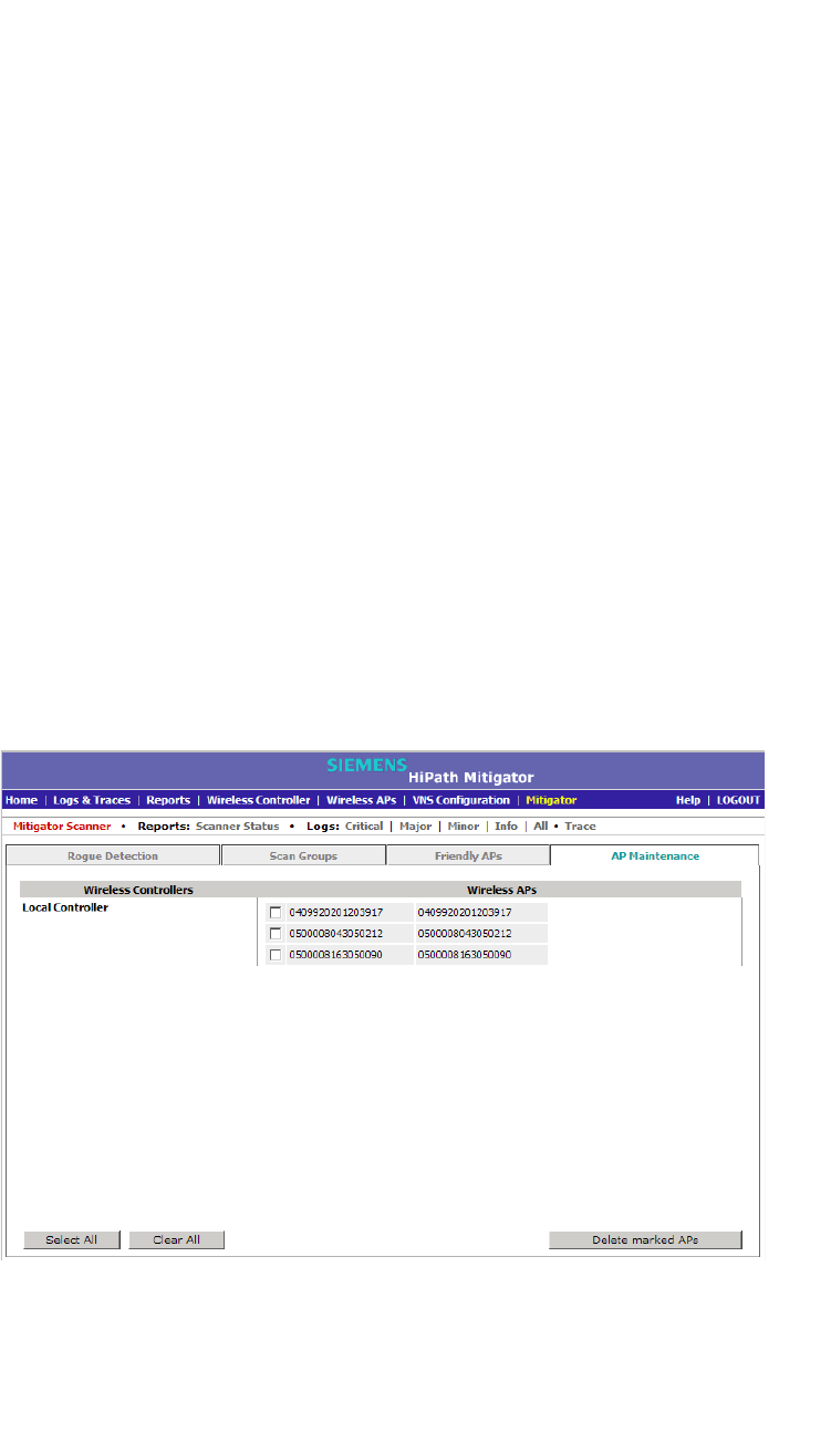
Working with the Mitigator
hwc_mitigator.fm
Maintaining the Mitigator list of APs
9034530-02, March 2010
424 HiPath Wireless Controller, Access Points and Convergence Software V7.11, User Guide
4. Click Delete. The selected access point is removed from the Friendly AP
Definitions list.
5. To save your changes, click Save.
To modify a friendly AP:
1. From the main menu, click Mitigator. The Mitigator screen is displayed.
2. Click the Friendly APs tab.
3. In the Friendly AP Definitions list, click the access point you want to modify.
4. Modify the access point by making the appropriate changes.
5. To save your changes, click Save.
10.7 Maintaining the Mitigator list of APs
To maintain the Wireless APs:
1. From the main menu, click Mitigator. The Mitigator screen is displayed.
2. Click the AP Maintenance tab. Inactive APs and known third-party APs are
displayed.
3. Select the applicable APs.
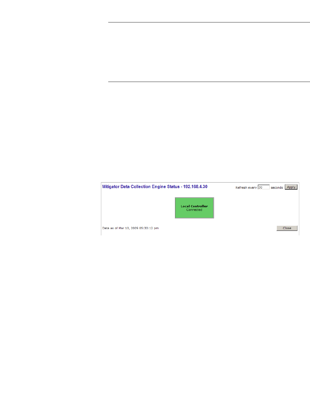
hwc_mitigator.fm
Working with the Mitigator
Viewing the Scanner Status report
9034530-02, March 2010
HiPath Wireless Controller, Access Points and Convergence Software V7.11, User Guide 425
4. To delete the selected APs, click Delete marked APs.
Note: The selected APs are deleted from the Mitigator database, not from the
HiPath Wireless Controller database. You can delete the APs from the HiPath
Wireless Controller database after you delete them from the Wireless AP
Configuration Access Approval screen of the corresponding RF Data
Collector Engine. You can also delete the selected third-party APs if they are
removed from the corresponding VNS in the RF Collector Engine, or if that
VNS has been deleted from the VNS list.
10.8 Viewing the Scanner Status report
When the Mitigator is enabled, you can view a report on the connection status of
the RF Data Collector Engines with the Analysis Engine.
To view the Mitigator scanner engine status display:
1. From the main menu, click Mitigator. The Mitigator screen is displayed.
2. Click the Reports: Scanner Status. The Scanner Status report is displayed.
The boxes display the IP address of the Data Collector engine. The status of the
Data Collector engine is indicated by one of the following colors:
•Green – The Analysis Engine has connection with the Data Collector on that
HiPath Wireless Controller.
•Yellow – The Analysis Engine has connected to the communication system
of the other controller, but has not synchronized with the Data Collector.
Ensure that the Data Collector is running on the remote controller.
•Red – The Analysis Engine is aware of the Data Collector and attempting
connection.

Working with the Mitigator
hwc_mitigator.fm
Viewing the Scanner Status report
9034530-02, March 2010
426 HiPath Wireless Controller, Access Points and Convergence Software V7.11, User Guide
If no box is displayed, the Analysis Engine is not attempting to connect with that
Data Collector Engine.
Note: If the box is displayed red and remains red, ensure your IP address is
correctly set up to point to an active controller. If the box remains yellow, ensure
the Data Collector is running on the remote controller.

hwc_reports.fm
9034530-02, March 2010
HiPath Wireless Controller, Access Points and Convergence Software V7.11, User Guide 427
Working with reports and displays
Viewing the displays
11 Working with reports and displays
This chapter describes the various reports and displays available in the HiPath
Wireless Controller, Access Points and Convergence Software system.
11.1 Viewing the displays
The following displays are available in the HiPath Wireless Controller, Access
Points and Convergence Software system:
•Active Wireless APs
•Active Clients by Wireless AP
•Active Clients by VNS
•Policy Filter Statistics
•Topology Filter Statistics
•Topology Statistics
•RADIUS Statistics
•Wireless Controller Port Statistics
•Wireless AP Availability
•Wired Ethernet Statistics by Wireless AP
•Wireless Statistics by Wireless AP
•Admission Control Statistics by Wireless AP
•Client Location in Mobility Zone
•Mobility Tunnel Matrix
•WDS VNS Wireless AP Statistics
•External Connections Statistics
•System Information
•Manufacturing Information
Note: The Client Location in Mobility Zone and Mobility Tunnel Matrix
displays only appear if the mobility manager function has been enabled for the
controller. Otherwise, the Agent Mobility Tunnel Matrix display is listed.
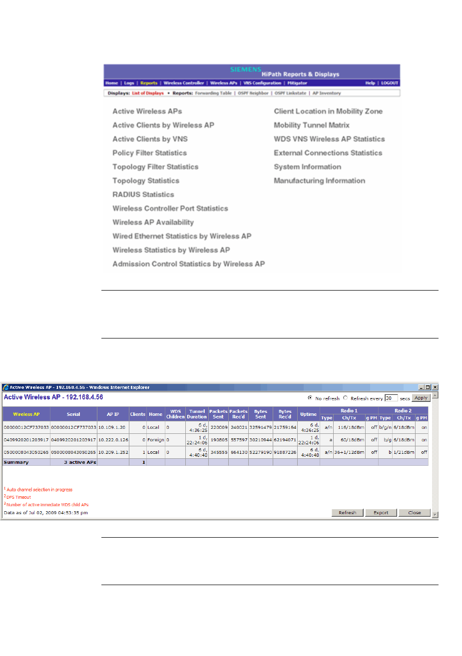
Working with reports and displays
hwc_reports.fm
Viewing the displays
9034530-02, March 2010
428 HiPath Wireless Controller, Access Points and Convergence Software V7.11, User Guide
To view reports and displays:
1. From the main menu, click Reports & Displays. The HiPath Reports &
Displays screen is displayed.
Note: The Client Location in Mobility Zone and Mobility Tunnel Matrix
displays only appear if the mobility manager function has been enabled for
the controller.
2. In the List of Displays, click the display you want to view.
Note: Statistics are expressed in relation to the AP. Therefore, Packets Sent
means the AP has sent that data to a client and Packets Rec’d means the
AP has received packets from a client.
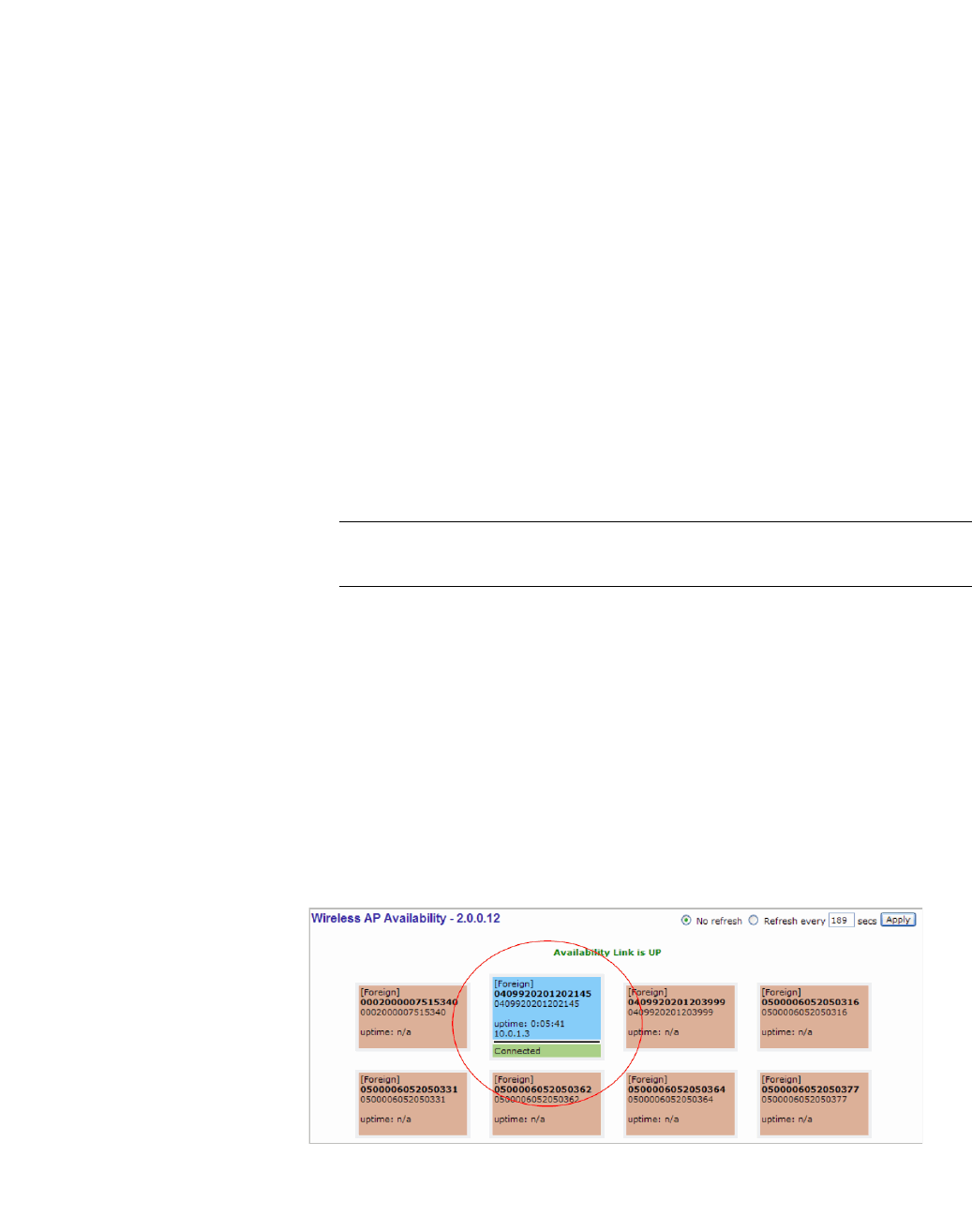
hwc_reports.fm
Working with reports and displays
Viewing the displays
9034530-02, March 2010
HiPath Wireless Controller, Access Points and Convergence Software V7.11, User Guide 429
11.1.1 Viewing the Wireless AP availability display
In session availability, the Wireless Availability report displays the state of both
the tunnels — active tunnel and backup tunnel — on both the primary and
secondary HiPath Wireless Controllers.
The report uses the Color Legend to indicate the tunnel state. The description of
the colors codes in the legend is given below:
•Green – Wireless AP has established an active tunnel.
•Blue – Wireless AP has established a backup tunnel.
•Red – Wireless AP is not connected.
In the report, each Wireless AP is represented by a box.
•The label, Foreign or Local, indicates whether the Wireless AP is local or
foreign on the HiPath Wireless Controller.
•The color in the upper pane of the box represents the state of the tunnel that
is established to the current HiPath Wireless Controller.
Note: The current HiPath Wireless Controller is the one on which the
Wireless AP Availability report is viewed.
•The color in the lower pane of the box represents the state of the tunnel that
is established with the other HiPath Wireless Controller.
For the ease of understanding, take the example of the following scenario:
•HWC1 and HWC2 are paired in session availability
•A Wireless AP has established an active tunnel to HWC1.
•The same Wireless AP has established a backup tunnel to HWC2.
If you open the Wireless AP Availability report on HWC2, the report will appear
as follows:

Working with reports and displays
hwc_reports.fm
Viewing the displays
9034530-02, March 2010
430 HiPath Wireless Controller, Access Points and Convergence Software V7.11, User Guide
In the above example, the circled Wireless AP has established a backup tunnel
to the foreign (secondary) HiPath Wireless Controller, and an active tunnel to the
local (Primary) HiPath Wireless Controller.
11.1.2 Viewing statistics for Wireless APs
Several displays are snapshots of activity at that point in time on a selected
Wireless AP:
•Wired Ethernet Statistics by Wireless AP
•Wireless Statistics by Wireless AP
•Active Clients by Wireless AP
•WDS VNS Wireless AP Statistics
•Admission Control Statistics by Wireless AP
The statistics displayed are those defined in the 802.11 MIB, in the IEEE 802.11
standard.
The following Wireless AP displays allow you to search for clients, either by user
name, MAC address, or IP address that are associated to the Wireless APs.
•Active Clients by Wireless AP
•Active Clients by VNS
•Admission Control Statistics by Wireless AP
You can also use the Select All and Deselect All buttons for selecting the
Wireless AP on those displays.
To view wired Ethernet statistics by Wireless AP:
1. From the main menu, click Reports & Displays. The HiPath Reports &
Displays screen is displayed.
2. Click the Wired Ethernet Statistics by Wireless AP display option. The
Wired Ethernet Statistics by Wireless APs display opens in a new browser
window.
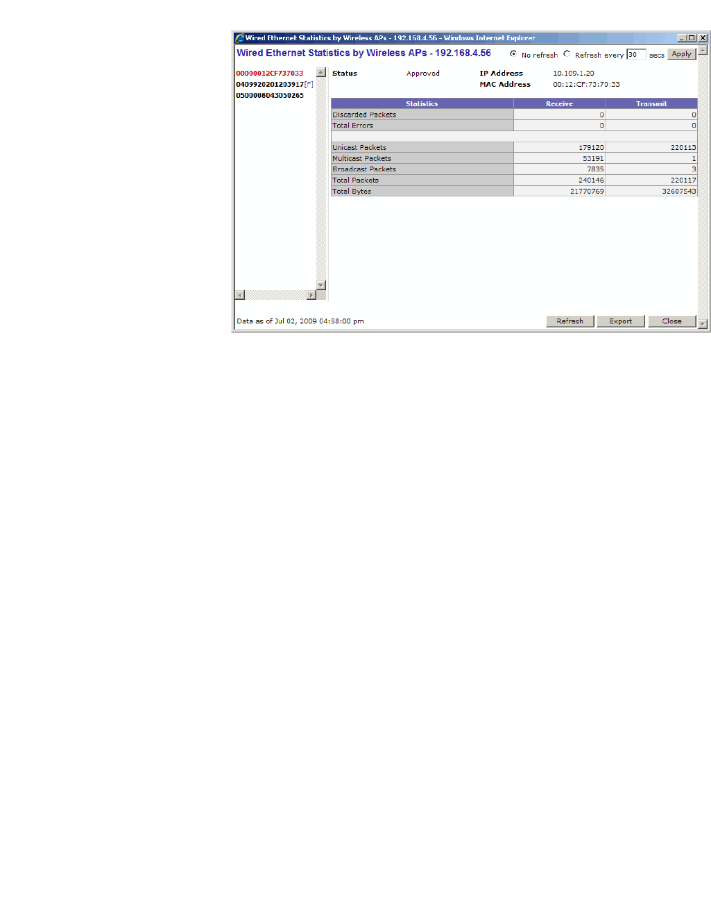
hwc_reports.fm
Working with reports and displays
Viewing the displays
9034530-02, March 2010
HiPath Wireless Controller, Access Points and Convergence Software V7.11, User Guide 431
3. In the Wired Ethernet Statistics by Wireless APs display, click a registered
Wireless AP to display its information.
To view Wireless Statistics by Wireless AP:
1. From the main menu, click Reports & Displays. The HiPath Reports &
Displays screen is displayed.
2. Click the Wireless Statistics by Wireless AP display option. The Wireless
Statistics by Wireless APs display opens in a new browser window.
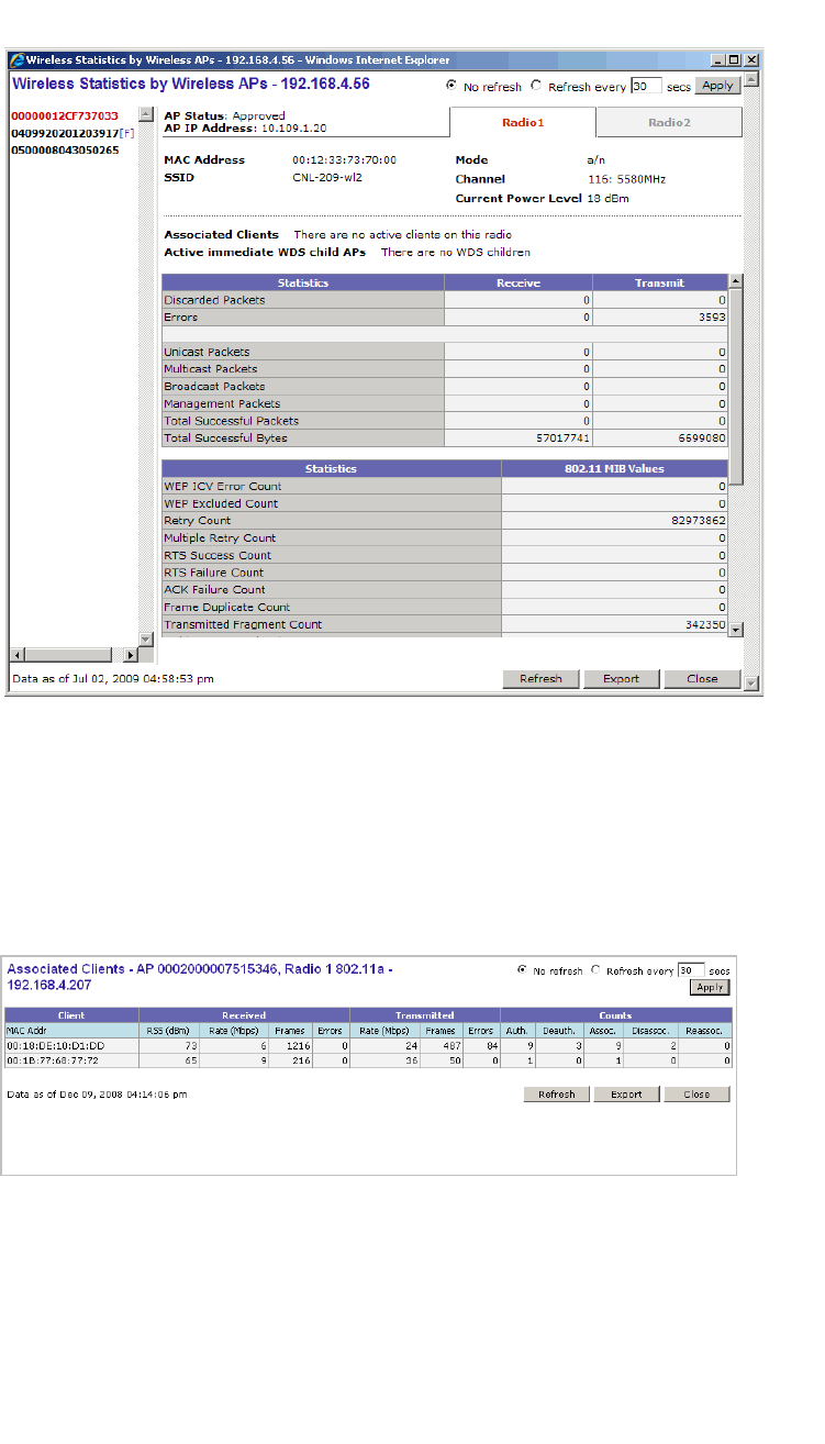
Working with reports and displays
hwc_reports.fm
Viewing the displays
9034530-02, March 2010
432 HiPath Wireless Controller, Access Points and Convergence Software V7.11, User Guide
3. In the Wireless Statistics by Wireless APs display, click a registered
Wireless AP to display its information.
4. Click the appropriate tab to display information for each Radio on the
Wireless AP.
5. To view information on the associated clients, click View Clients. The
Associated Clients display opens in a new browser window.
To view Active Clients by Wireless AP statistics:
1. From the main menu, click Reports & Displays. The HiPath Reports &
Displays screen is displayed.
2. Click the Active Clients by Wireless APs display option. The Active Clients
by Wireless APs display opens in a new browser window.
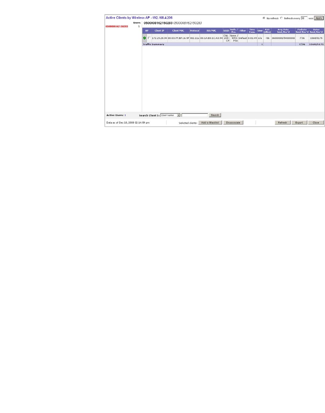
hwc_reports.fm
Working with reports and displays
Viewing the displays
9034530-02, March 2010
HiPath Wireless Controller, Access Points and Convergence Software V7.11, User Guide 433
•Statistics are expressed in respect of the AP. Therefore, Packets Sent
means the AP has sent that data to a client and Packets Rec’d means
the AP has received packets from a client.
•If the client is authenticated, a green check mark icon is displayed in the
first column of the display.
• Time Conn is the length of time that a client has been on the system, not
just on an AP. If the client roams from one AP to another, the session
stays, therefore Time Conn does not reset.
•A client is displayed as soon as the client connects (or after a refresh of
the screen). The client disappears as soon as it times out.
•The RSS (received signal strength) of a client is the average of the
transmitted and received RSS on hardware platforms where both values
are available.
To view WDS VNS Wireless AP Statistics:
1. From the main menu, click Reports & Displays. The HiPath Reports &
Displays screen is displayed.
2. Click the WDS Wireless AP Statistics display option. The WDS VNS
Wireless AP Statistics display opens in a new browser window.
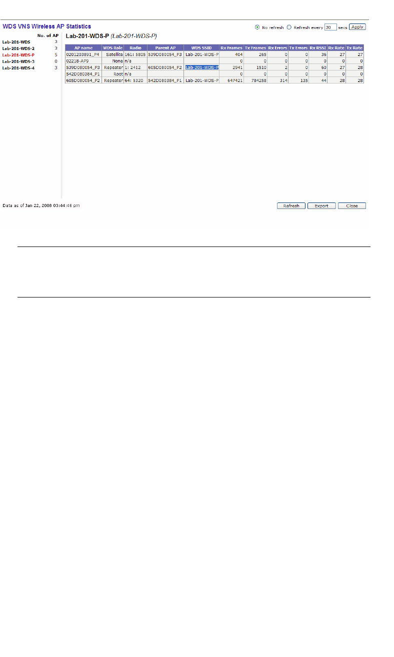
Working with reports and displays
hwc_reports.fm
Viewing the displays
9034530-02, March 2010
434 HiPath Wireless Controller, Access Points and Convergence Software V7.11, User Guide
Note: The Rx RSSI value on the WDS VNS Wireless AP Statistics display
represents the received signal strength. The minimum value is 1 and maximum
value is 60. The higher the RSSI value, the stronger the received signal.
To view Admission Control Statistics by Wireless AP:
1. From the main menu, click Reports & Displays. The HiPath Reports &
Displays screen is displayed.
2. Click the Admission Control Statistics by Wireless AP display option. The
Admission Control Statistics by Wireless AP display opens in a new
browser window.
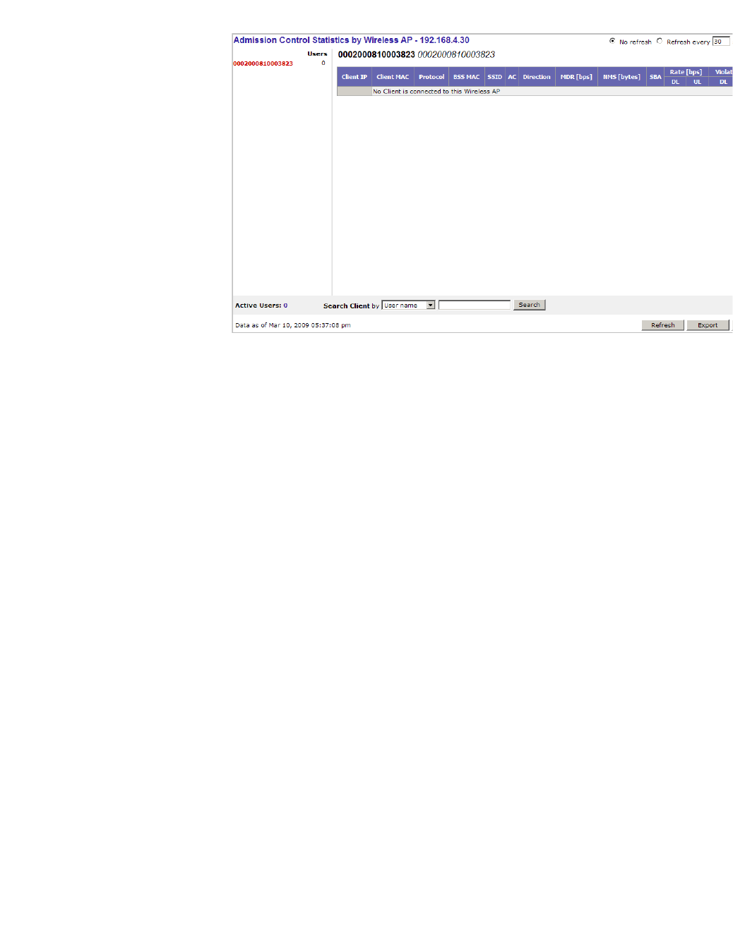
hwc_reports.fm
Working with reports and displays
Viewing the displays
9034530-02, March 2010
HiPath Wireless Controller, Access Points and Convergence Software V7.11, User Guide 435
3. In the Admission Control Statistics by Wireless AP display, click a
registered Wireless AP to display its information:
4. The Admission Control Statistics by Wireless AP lists the TSPEC statistics
associated with this Wireless AP:
•AC – Access class where TSPEC is applied,
•Direction – Uplink, Downlink or Bidirectional,
•MDR – Mean Data Rate
•NMS – Nominal Packet Size
•SBA – Surplus Bandwidth (ratio)
The following two statistics are of the measured traffic:
•Rate – Rate in 30 second intervals (uplink and downlink)
• Violation – Number of bits in excess in the last 30 seconds (uplink and
downlink)
11.1.3 Viewing the System Information and
Manufacturing Information displays
System Information – Displays system information including memory usage and
CPU and board temperatures.
Manufacturing Information – Displays manufacturing information including the
card serial number and CPU type and frequency.
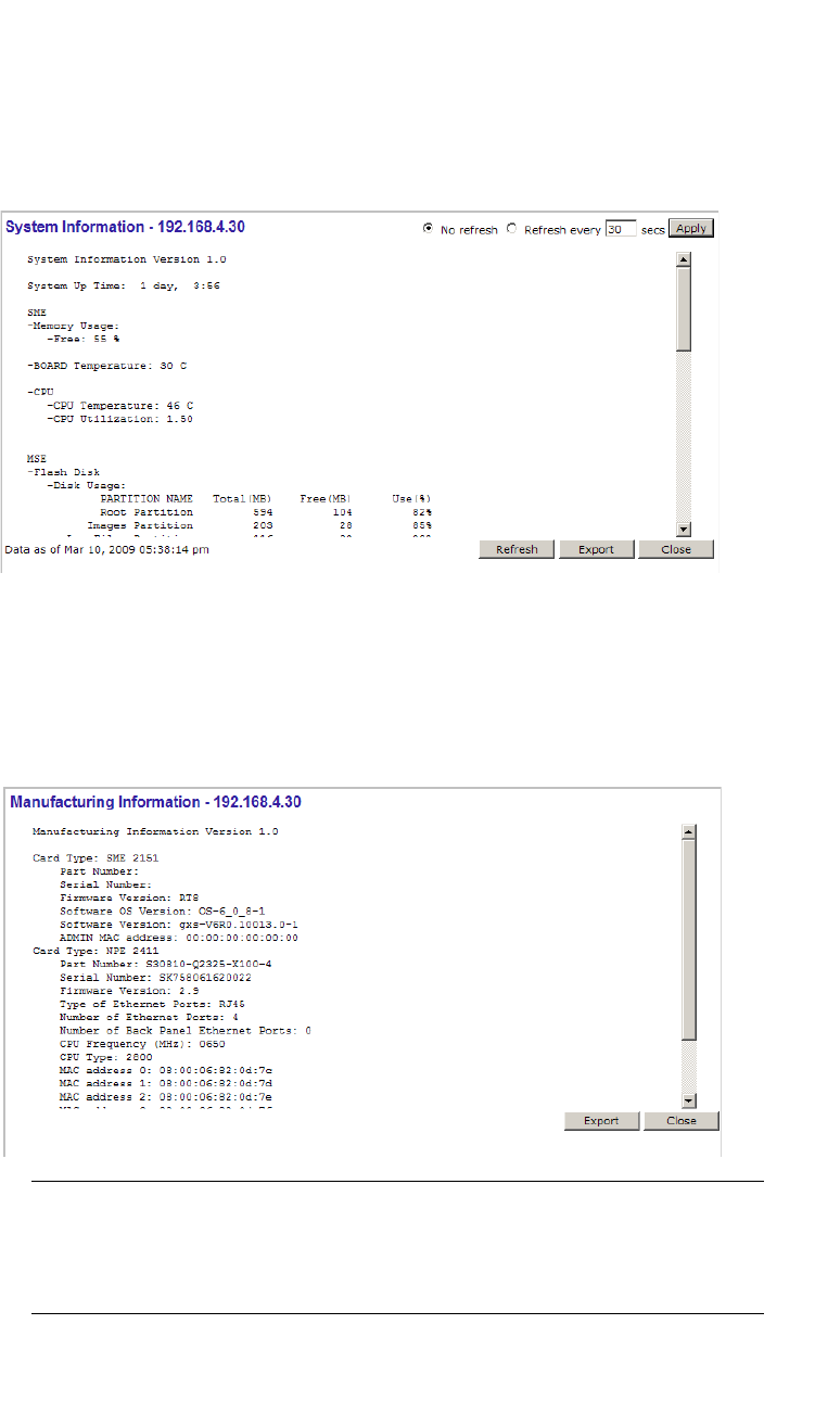
Working with reports and displays
hwc_reports.fm
Viewing the displays
9034530-02, March 2010
436 HiPath Wireless Controller, Access Points and Convergence Software V7.11, User Guide
To view system information:
1. From the main menu, click Reports & Displays. The HiPath Reports &
Displays screen is displayed.
2. Click the System Information display option. The System Information
display opens in a new browser window.
To view manufacturing information:
1. From the main menu, click Reports & Displays. The HiPath Reports &
Displays screen is displayed.
2. Click the Manufacturing Information display option. The Manufacturing
Information display opens in a new browser window.
Note: In the latest models of the HiPath Wireless Controller C2400, the
IXP2800 Network Processor in the NPE Card has been replaced by the new
IXP2805 Network Processor. Consequently, the Manufacturing Information
in all such latest models displays CPU Type as 2805.
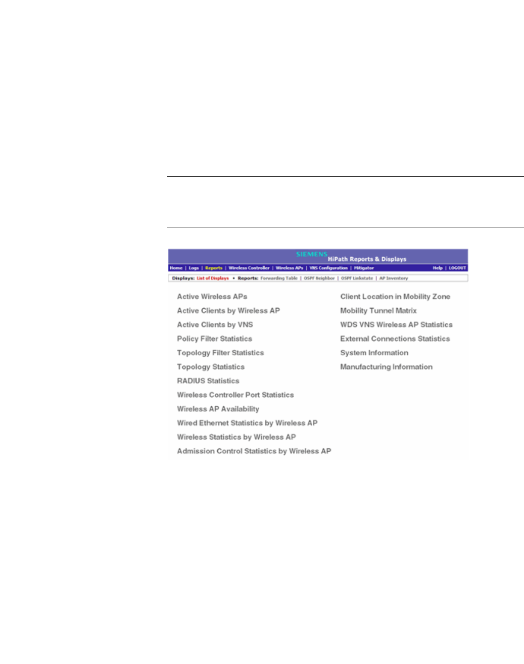
hwc_reports.fm
Working with reports and displays
Viewing the displays
9034530-02, March 2010
HiPath Wireless Controller, Access Points and Convergence Software V7.11, User Guide 437
11.1.4 Viewing displays for the mobility manager
When a HiPath Wireless Controller has been configured as a mobility manager,
two additional displays appear as options on the HiPath Reports & Displays
screen:
• Client Location in Mobility Zone – Displays the active wireless clients and
their status
• Mobility Tunnel Matrix – Displays a cross-connection view of the state of
inter-controller tunnels, as well as relative loading for user distribution across
the mobility domain
Note: The Client Location in Mobility Zone and Mobility Tunnel Matrix
displays only appear if the mobility manager function has been enabled for the
controller. Otherwise, the Agent Mobility Tunnel Matrix display is listed.
To view mobility manager displays:
1. From the main menu, click Reports & Displays. The HiPath Reports &
Displays screen is displayed.
2. Click the appropriate mobility manager display:
•Client Location in Mobility Zone
•Mobility Tunnel Matrix
The colored status indicates the following:
•Green – The mobility manager is in communication with an agent and the
data tunnel has been successfully established.

Working with reports and displays
hwc_reports.fm
Viewing the displays
9034530-02, March 2010
438 HiPath Wireless Controller, Access Points and Convergence Software V7.11, User Guide
•Yellow – The mobility manager is in communication with an agent but the
data tunnel is not yet successfully established.
•Red – The mobility manager is not in communication with an agent and there
is no data tunnel.
Client Location in Mobility Zone
You can do the following:
•Sort this display by home or foreign controller
•Search for a client by MAC address, user name, or IP address, and typing the
search criteria in the box
•Define the refresh rates for this display
•Export this information as an xml file
Mobility Tunnel Matrix
•Provides connectivity matrix of mobility state
•Provides a view of:
•Tunnel state
•If a tunnel between controllers is reported down, it is highlighted in red
•If only a control tunnel is present, it is highlighted in yellow
•If data and control tunnels are fully established, it is highlighted in green
•Tunnel Uptime
•Number of clients roamed (Mobility loading)
•Local controller loading
•Mobility membership list
A HiPath Wireless Controller is only removed from the mobility matrix if it is
explicitly removed by the administrator from the Mobility permission list. If a
particular link between controllers, or the controller is down, the corresponding
matrix connections are identified in red color to identify the link.
The Active Clients by VNS report for the controller on which the user is home
(home controller) will display the known user characteristics (IP, statistics, etc.).
On the foreign controller, the Clients by VNS report does not show users that
have roamed from other controllers, since the users remain associated with the
home controller's VNS.

hwc_reports.fm
Working with reports and displays
Viewing reports
9034530-02, March 2010
HiPath Wireless Controller, Access Points and Convergence Software V7.11, User Guide 439
The Active Clients by AP report on each controller will show both the loading of
local and foreign users (users roamed from other controllers) that are taking
resources on the AP.
Note: Although you can set the screen refresh period less than 30 seconds, the
screen will not be refreshed quicker than 30 seconds. The screen will be
refreshed according to the value you set only if you set the value above 30
seconds.
11.2 Viewing reports
The following reports are available in the HiPath Wireless Controller, Access
Points and Convergence Software system:
•Forwarding Table (routes defined on the Routing Protocols screens)
•OSPF Neighbor (if OSPF is enabled on the Routing Protocols screens)
•OSPF Linkstate (if OSPF is enabled on the Routing Protocols screens)
•AP Inventory (a consolidated summary of Wireless AP setup)
To view reports:
1. From the main menu, click Reports & Displays. The HiPath Reports &
Displays screen is displayed.
2. In the Reports list, click the report you want to view:
•Forwarding Table
•OSPF Neighbor
•OSPF Linkstate
•AP Inventory
Note: The AP Inventory report opens in a new browser window. All other
reports appear in the current browser window.
The following is an example of a Forwarding Table report:
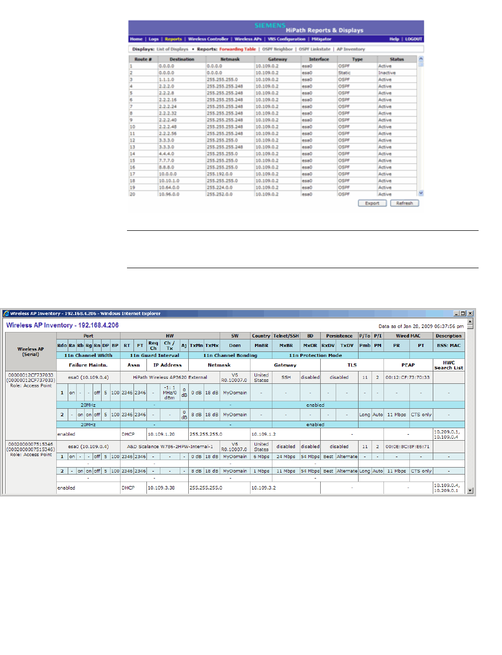
Working with reports and displays
hwc_reports.fm
Viewing reports
9034530-02, March 2010
440 HiPath Wireless Controller, Access Points and Convergence Software V7.11, User Guide
Note: If you open only automatically refreshed reports, the Web management
session timer will not be updated or reset. Your session will eventually time out.
The following is an example of the AP Inventory report:
The following is a description of the column names and abbreviations found in the
AP Inventory report:
•Rdo – Radios: 1 or 2.
•Ra – 802.11a radio. The data entry for an Wireless AP indicates whether the
a radio is on or off.
•Rb – 802.11b protocol enabled. Possible values are on or off.
•Rg – 802.11g protocol enabled. Possible values are on or off.

hwc_reports.fm
Working with reports and displays
Viewing reports
9034530-02, March 2010
HiPath Wireless Controller, Access Points and Convergence Software V7.11, User Guide 441
•Rn – 802.11n protocol enabled. Possible values are on or off.
•DP – DTIM period
•BP – Beacon Period
•SRL – Short Retry Limit
•LRL – Long Retry Limit
•RT – RTS Threshold
•FT – Fragmentation Threshold
•Ch – Channel served by the corresponding radio.
•PL – Power Level (Defined in the Wireless AP radio properties screens.)
•BR – Basic Rate (Only applies to Wireless APs running 3.1 or earlier.)
•ORS – Operational Rate Set (Only applies to Wireless APs running 3.1 or
earlier.)
•MnBR – Minimum Basic Rate (For more information, see the Wireless AP
radio configuration tabs.)
•MxBR – Maximum Basic Rate
•MxOR – Maximum Operational Rate
•RxDV – Receive Diversity
•TxDV – Tx Diversity
•Pmb – Preamble (long, short)
•PM – Protection Mode
•PR – Protection Rate
•PT – Protection Type
•BSS – Basic Service Set
•MAC – MAC address
•BSS: MAC – Also called BSSID, this is the MAC address of a (virtual)
wireless interface on which the Wireless AP serves a BSS/VNS. There could
be 8 per radio.
•Port – Ethernet Port and associated IP address of the interface on the HiPath
Wireless Controller through which the Wireless AP communicates.
•HW – Hardware version of the Wireless AP.
•SW – Software version executing on theWireless AP.
•TA – Telnet access (enabled or disabled).

Working with reports and displays
hwc_reports.fm
Viewing reports
9034530-02, March 2010
442 HiPath Wireless Controller, Access Points and Convergence Software V7.11, User Guide
•BD – Broadcast disassociation (enabled or disabled). If enabled, whenever
the Wireless AP is going offline in a controlled fashion it will send the
disassociation frame to all its clients as a broadcast.
•DV – Diversity
•P/To – Poll timeout. If polling is enabled, a numeric value.
•P/I – Poll interval. If polling is enabled, a numeric value.
•Wired MAC – The physical address of the Wireless AP's wired Ethernet
interface.
• Description – As defined on the AP Properties screen.
•Failure Maintn. – Maintain MU sessions on Wireless AP when the Wireless
AP loses the connection to the HiPath Wireless Controller.
•Assn – Assignment (address assignment method)
• Static Cfg – Wireless AP's IP address if statically configured (same as the
Static Values radio button on the AP Static Configuration screen).
• Static Cfg IP – Statically Configured IP. If the Wireless AP's IP address is
configured statically, the IP address is displayed.
•Netmask – If the Wireless AP's IP address is configured statically, the
netmask that is statically configured for the Wireless AP.
• Gateway – If the Wireless AP's IP address is configured statically, the IP
address of the gateway router that the Wireless AP will use.
• HWC Search List – The list of IP addresses that the Wireless AP is
configured to try to connect to in the event that the current connection to the
HiPath Wireless Controller is lost.
To export and save a report in XML:
1. On the report screen, click Export. A Windows File Download dialog is
displayed.
2. Click Save. A Windows Save As dialog is displayed.
Note: If your default XML viewer is Internet Explorer or Netscape, clicking
Open will open the exported data to your display screen. You must right-click
to go back to the export display. The XML data file will not be saved to your
local drive.
3. Browse to the location where you want to save the exported XML data file,
and in the File name box enter an appropriate name for the file.
4. Click Save. The XML data file is saved in the specified location.

hwc_reports.fm
Working with reports and displays
Call Detail Records (CDRs)
9034530-02, March 2010
HiPath Wireless Controller, Access Points and Convergence Software V7.11, User Guide 443
11.3 Call Detail Records (CDRs)
You can configure the HiPath Wireless Controller to generate Call Detail Records
(CDRs), which contain usage information about each wireless session per VNS.
For more information on how to configure the HiPath Wireless Controller to
generate CDRs, refer to Section 6.9.3.2, “Defining accounting methods for a
WLAN Service”, on page 321.
CDRs are located in a CDR directory on the HiPath Wireless Controller. To
access the CDR file, you must first back up the file on the local drive, and then
upload it to a remote server. After the CDR file is uploaded to a remote server,
you can work with the file to view CDRs or import the records to a reporting tool.
You can back up and upload the file on the remote server either via the HiPath
Wireless Assistant (GUI) or CLI.
11.3.1 CDR files
CDRs are written to a file on the HiPath Wireless Controller. The filename is
based on the creation time of the CDR file with the following format:
YYYYMMDDhhmmss.<ext>
• YYYY – Four digit year
•MM – Two digit month, padded with a leading zero if the month number is less
than 10
•DD – Two digit day of the month, padded with a leading zero if the day
number is less than 10
•hh – Two digit hour, padded with a leading zero if the hour number is less than
10
•mm – Two digit minute, padded with a leading zero if the minute number is
less than 10
•ss – Two digit second, padded with a leading zero if the second number is
less than 10
• <ext> – File extension, either .work or .dat
11.3.2 CDR file types
The following two types of CDR files exist in the CDR directory on the HiPath
Wireless Controller C2400:

Working with reports and displays
hwc_reports.fm
Call Detail Records (CDRs)
9034530-02, March 2010
444 HiPath Wireless Controller, Access Points and Convergence Software V7.11, User Guide
•.work – This file is the active file that is being updated by the accounting
system. The file is closed and renamed with the .dat extension when it attains
its maximum size — 16 MB — or it has been open for the maximum allowed
duration — 12 hours. You can back up and copy .work file from the HiPath
Wireless Controller to a remote server.
•.dat – This file is the inactive file that contains the archived account records.
You can back up and copy the .dat file from the HiPath Wireless Controller to
a remote server.
Note: The CDR directory on the HiPath Wireless Controller only has two files —
a .work file and a .dat file. When the .work file attains its maximum size of 16
MB, or it has been open for 12 hours, it is saved as a .dat file. This new .dat file
overwrites the existing .dat file. If you want to copy the existing .dat file, you must
do so before it is overwritten by the new .dat file.
11.3.3 CDR file format
A CDR file contains a sequence of CDR records. The file is a standard ASCII text
file. Records are separated by a sequence of dashes followed by a line break.
The individual fields of a record are reported one per line, in “field=value’ format.
The following table describes the records that are displayed in a CDR file.
Note: Most of the CDR records are typical RADIUS server attributes. For more
information, refer to the user manual of your RADIUS server.
CDR Records Description
Acct-Session-ID A unique CDR ID
User-Name The name of the user, who was authenticated.
Filter-ID The name of the filter list for the user.
Acct-Interim-Interval The number of seconds between interim accounting
updates.
Session-Timeout The maximum number of seconds of service to be
provided to the user before termination of the session.
Class This field is copied from the Access-Accept message sent
by the RADIUS server during authentication.
Acct-Status-Type Indicates whether this Accounting-Request marks the
beginning of the user service (Start) or the end (Stop).
Table 36 CDR Records and their description

hwc_reports.fm
Working with reports and displays
Call Detail Records (CDRs)
9034530-02, March 2010
HiPath Wireless Controller, Access Points and Convergence Software V7.11, User Guide 445
Acct-Delay-Time Indicates how many seconds the client tried to
authenticate send this record for, and can be subtracted
from the time of arrival on the server to find the
approximate time of the event generating this Accounting-
Request.
Acct-Authentic Indicates how the user was authenticated, whether by
RADIUS (AAA), Local (Internal CP) or Remote (External
CP). The field displays one of the following values:
•1 – AAA authentication
•2 – Internal CP authentication
•3 – External CP authentication
Framed-IP-Address Indicates the address to be configured for the user
Connect-Info This field is sent from the NAS to indicate the nature of the
users’ connection — 802.11b for Radio b/g or 802.11a for
radio a.
NAS-Port-Type Indicates RADIUS NAS Port Type is Wireless 802.11
Called-Station-ID The Wireless AP’s MAC address.
Calling-Station-ID The client’s MAC address.
Siemens-AP-Serial The Wireless AP’s serial number.
Siemens-AP-Name The Wireless AP’s name.
Siemens-VNS-Name The VNS name on which the session took place.
Siemens-SSID The SSID name on which the session took place.
Acct-Session-Time The number of seconds the user has received the service.
Acct-Output-Packets The number of packets that were sent to the port in the
course of delivering this service to a framed user.
Acct-Input-Packets The number of packets that have been received from the
port over the course of this service being provided to a
Framed User.
Acct-Output-Octets The number of octets that were sent to the port in the
course of delivering the service.
Acct-Input-Octets The number of octets that were received from the port
over the course of the service.
Acct-Terminate-Cause Indicates how the session was terminated. The field
displays one of the following values:
•1 – User Request
4 – Idle Timeout
•5 – Session Timeout
•6 – Admin Reset
•11 – NAS Reboot
•16 – Callback
•17 – User Error
Authenticated_time Indicates the time at which the client was authenticated.
The time is in the following format: Date hh:mm:ss. For
example, April 21 2008 14:50:24
CDR Records Description
Table 36 CDR Records and their description (Continuation)

Working with reports and displays
hwc_reports.fm
Call Detail Records (CDRs)
9034530-02, March 2010
446 HiPath Wireless Controller, Access Points and Convergence Software V7.11, User Guide
11.3.4 Viewing CDRs
The following is a high-level overview of how to view CDRs:
•Back up the CDR files on the local drive of the HiPath Wireless Controller.
•Copy the CDR files from the HiPath Wireless Controller to the remote server.
•Unzip the file.
•Download the CDR files from the remote server to view CDRs.
Note: You can not access the CDR files directly from the CDR directory.
When you back up CDRs, both the .work and .dat files are zipped into a single
.zip file. This .zip file is uploaded on the remote server. You can unzip this file from
the remote server to extract the .work and .dat files.
You can back up and upload the files on the remote server either via the HiPath
Wireless Assistant (GUI) or CLI.
This section describes how to back up and copy the CDR files to a remote server
via the HiPath Wireless Assistant (GUI). For more information on how to copy the
CDR file to the remote server via CLI, refer to the HiPath Wireless Controller,
Access Points and Convergence Software CLI Reference Guide.
Disassociation_time Indicates the time at which the client was disassociated
from the Wireless AP. The time is in the following format:
Date hh:mm:ss. For example, April 21 2008 14:57:20.
CDR Records Description
Table 36 CDR Records and their description (Continuation)
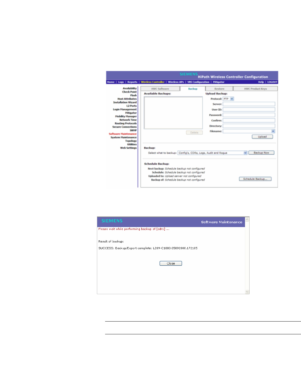
hwc_reports.fm
Working with reports and displays
Call Detail Records (CDRs)
9034530-02, March 2010
HiPath Wireless Controller, Access Points and Convergence Software V7.11, User Guide 447
To back up and copy the CDR files to a remote server:
1. From the main menu, click Wireless Controller Configuration. The
Wireless Controller Configuration screen is displayed.
2. In the left pane, click Software Maintenance. The Software Maintenance
screen is displayed.
3. Click the Backup tab.
4. From the Select what to backup drop-down menu, click CDRs only, and
then click Backup Now. The following window displays the backup status.
5. To close the window, click Close. The backed up file is displayed in the
Available Backups box.
Note: The .work and .dat files are zipped into a single file.
6. To upload a backup, in the Upload Backup section, do the following:
•Protocol – Click the file transfer protocol you want to use to upload the
backup file, SCP or FTP.
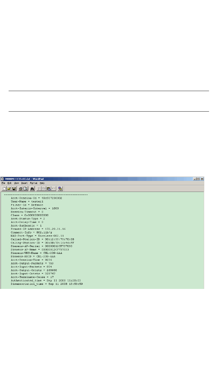
Working with reports and displays
hwc_reports.fm
Call Detail Records (CDRs)
9034530-02, March 2010
448 HiPath Wireless Controller, Access Points and Convergence Software V7.11, User Guide
•Server – Type the IP address of the server where the backup will be
stored.
• User ID – Type the user ID to log in to the server.
• Password – The password to log in to the server.
• Confirm – The password to confirm the password.
• Directory – The directory in which you want to upload the CDR file.
• Filename – Type the zipped CDR file name.
Note: After you back up CDRs, the zipped CDR file name is selected by
default in the Filename box.
7. In the Upload Backup section, click Upload. The .zip file is uploaded on to
the server.
8. Unzip the file. The two CDR files — .work and .dat — are visible on the
server.
9. To view CDRs, download the files.
Figure 28 Sample .dat file

hwc_ongoing.fm
9034530-02, March 2010
HiPath Wireless Controller, Access Points and Convergence Software V7.11, User Guide 449
Performing system administration
Performing Wireless AP client management
12 Performing system administration
This chapter describes system administration processes, including:
•Performing Wireless AP client management
•Defining HiPath Wireless Assistant administrators and login groups
•Configuring Web session timeouts
12.1 Performing Wireless AP client management
There are times when for business, service, or security reasons you want to cut
the connection with a particular wireless device. You can view all the associated
wireless devices, by MAC address, on a selected Wireless AP and do the
following:
•Disassociate a selected wireless device from its Wireless AP.
•Add a selected wireless device's MAC address to a blacklist of wireless
clients that will not be allowed to associate with the Wireless AP.
•Backup and restore the HiPath Wireless Controller database. For more
information, see the HiPath Wireless Controller, Access Points and
Convergence Software Maintenance Guide.
12.1.1 Disassociating a client
In addition to the following procedure below, you can also disassociate wireless
users directly from the Active Clients by VNS screen. For more information, see
Chapter 11, “Working with reports and displays”.
To disassociate a wireless device client:
1. From the main menu, click Wireless AP Configuration. The Wireless AP
Configuration screen is displayed.
2. In the left pane, click Client Management. The Disassociate tab is
displayed.
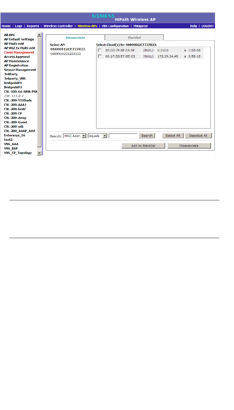
Performing system administration
hwc_ongoing.fm
Performing Wireless AP client management
9034530-02, March 2010
450 HiPath Wireless Controller, Access Points and Convergence Software V7.11, User Guide
3. In the Select AP list, click the AP you want to disassociate.
4. In the Select Client(s) list, select the checkbox next to the client you want to
disassociate.
Note: You can search for a client by MAC Address, IP Address or User ID,
by selecting the search parameters from the drop-down lists and typing a
search string in the Search box and clicking Search. You can also use the
Select All or Clear All buttons to help you select multiple clients.
5. Click Disassociate. The client's session terminates immediately.
12.1.2 Blacklisting a client
The Blacklist tab displays the current list of MAC addresses that are not allowed
to associate. A client is added to the blacklist by selecting it from a list of
associated APs or by typing its MAC address.
To blacklist a wireless device client:
1. From the main menu, click Wireless AP Configuration. The Wireless AP
Configuration screen is displayed.
2. In the left pane, click Client Management. The Disassociate tab is
displayed.
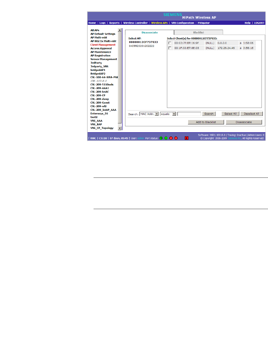
hwc_ongoing.fm
Performing system administration
Performing Wireless AP client management
9034530-02, March 2010
HiPath Wireless Controller, Access Points and Convergence Software V7.11, User Guide 451
3. In the Select AP list, click the AP you want to disassociate.
4. In the Select Client(s) list, select the checkbox next to the client you want to
disassociate, if applicable.
Note: You can search for a client by MAC Address, IP Address or User ID,
by selecting the search parameters from the drop-down lists and typing a
search string in the Search box and clicking Search. You can also use the
Select All or Clear All buttons to help you select multiple clients.
5. Click Add to Blacklist. The selected wireless client's MAC address is added
to the blacklist.
To blacklist a wireless device client using its MAC address:
1. From the main menu, click Wireless AP Configuration. The Wireless AP
Configuration screen is displayed.
2. In the left pane, click Client Management. The Disassociate tab is
displayed.
3. Click the Blacklist tab.
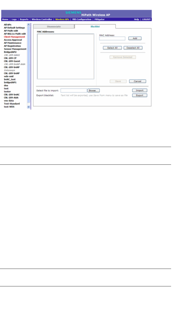
Performing system administration
hwc_ongoing.fm
Performing Wireless AP client management
9034530-02, March 2010
452 HiPath Wireless Controller, Access Points and Convergence Software V7.11, User Guide
4. To add a new MAC address to the blacklist, in the MAC Address box type
the client’s MAC address.
5. Click Add. The client is displayed in the MAC Addresses list.
Note: You can use the Select All or Clear All buttons to help you select
multiple clients.
6. To save your changes, click Save.
To clear an address from the blacklist:
1. From the main menu, click Wireless AP Configuration. The Wireless AP
Configuration screen is displayed.
2. In the left pane, click Client Management. The Disassociate tab is
displayed.
3. Click the Blacklist tab.
4. To clear an address from the blacklist, select the corresponding checkbox in
the MAC Addresses list.
5. Click Remove Selected. The selected client is removed from the list.
Note: You can use the Select All or Clear All buttons to help you select
multiple clients.
6. To save your changes, click Save.

hwc_ongoing.fm
Performing system administration
Defining HiPath Wireless Assistant administrators and login groups
9034530-02, March 2010
HiPath Wireless Controller, Access Points and Convergence Software V7.11, User Guide 453
To import a list of MAC addresses for the blacklist:
1. From the main menu, click Wireless AP Configuration. The Wireless AP
Configuration screen is displayed.
2. In the left pane, click Client Management. The Disassociate tab is
displayed.
3. Click the Blacklist tab.
4. Click Browse and navigate to the file of MAC addresses you want to import
and add to the blacklist.
5. Click the file, and then click Import. The list of MAC addresses is imported.
To export a list of MAC addresses for the blacklist:
1. From the main menu, click Wireless AP Configuration. The Wireless AP
Configuration screen is displayed.
2. In the left pane, click Client Management. The Disassociate tab is
displayed.
3. Click the Blacklist tab.
4. Click Export. The saved blacklist file is exported.
5. To export the current blacklist, use the browser’s save option to save the file
as a text (.txt) file. It is recommend that a descriptive file name is used.
12.2 Defining HiPath Wireless Assistant administrators and login groups
You can define the login user names and passwords for administrators that have
access to the HiPath Wireless Assistant. You can also assign them to a login
group — as full administrators, read-only administrators, or as GuestPortal
managers. For each user added, you can define and modify a user ID and
password.
• Full administrators – Users assigned to this login group have full
administrator access rights on the HiPath Wireless Controller. Full
administrators can manage all aspects of the HiPath Wireless Controller,
including GuestPortal user accounts.
• Read-only administrators – Users assigned to this login group have read-
only access rights on the HiPath Wireless Controller, including the
GuestPortal user accounts.
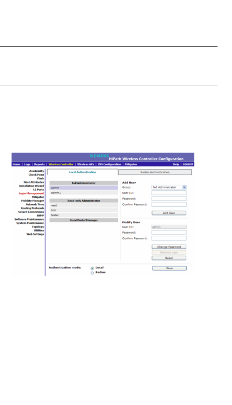
Performing system administration
hwc_ongoing.fm
Defining HiPath Wireless Assistant administrators and login groups
9034530-02, March 2010
454 HiPath Wireless Controller, Access Points and Convergence Software V7.11, User Guide
• GuestPortal managers – Users assigned to this login group can only
manage GuestPortal user accounts. Any user who logs on to the HiPath
Wireless Controller and is assigned to this group can only access the
GuestPortal Guest Administration page of the HiPath Wireless Assistant.
Note: When adding or modifying a user, note the following password character
constraints:
• Allowed characters include A-Z a-z 0-9 ~!@#$%^&*()_+|-=\{}[];<>?,.
• Characters not allowed include / ` ' " : and space is not valid.
To add a HiPath Wireless Controller administrator to a login group:
1. From the main menu, click Wireless Controller Configuration. The
Wireless Controller Configuration screen is displayed.
2. In the left pane, click Login Management. The Local Authentication tab is
displayed.
3. In the Group drop-down list, click one of the following:
• Full Administrator – Users assigned to this login group have full
administrator access rights on the HiPath Wireless Controller.
Full administrators can manage GuestPortal user accounts.
• Read-only Administrator – Users assigned to this login group have
read-only access rights on the HiPath Wireless Controller.
Read-only administrators have read access to the GuestPortal user
accounts.

hwc_ongoing.fm
Performing system administration
Defining HiPath Wireless Assistant administrators and login groups
9034530-02, March 2010
HiPath Wireless Controller, Access Points and Convergence Software V7.11, User Guide 455
• GuestPortal Manager – Users assigned to this login group can only
manage GuestPortal user accounts. Any user who logs on to the HiPath
Wireless Controller and is assigned to this group can only access the
GuestPortal Guest Administration page of the HiPath Wireless
Assistant. For more information, see Section 12.2.1, “Working with
GuestPortal Guest administration”, on page 455.
4. In the User ID box, type the user ID for the new user. A user ID can only be
used once, in only one category.
5. In the Password box, type the password for the new user.
6. In the Confirm Password, re-type the password.
7. Click Add User. The new user is added to the appropriate login group list.
To modify a HiPath Wireless Controller administrator’s password:
1. From the main menu, click Wireless Controller Configuration. The
Wireless Controller Configuration screen is displayed.
2. In the left pane, click Login Management. The Local Authentication tab is
displayed.
3. Click the user whose password you want to modify.
4. In the Password box, type the new password for the user.
5. In the Confirm Password, re-type the new password.
6. To change the password, click Change Password.
To remove a HiPath Wireless Controller administrator:
1. From the main menu, click Wireless Controller Configuration. The
Wireless Controller Configuration screen is displayed.
2. In the left pane, click Login Management. The Local Authentication tab is
displayed.
3. Click the user you want to remove.
4. Click Remove user. The user is removed from the list.
12.2.1 Working with GuestPortal Guest
administration
A GuestPortal provides wireless device users with temporary guest network
services. A GuestPortal is serviced by a GuestPortal-dedicated VNS. The
GuestPortal-dedicated VNS is configured by an administrator with full
administrator access rights. For more information, see Section 6.5, “Working with
a GuestPortal VNS”, on page 285.
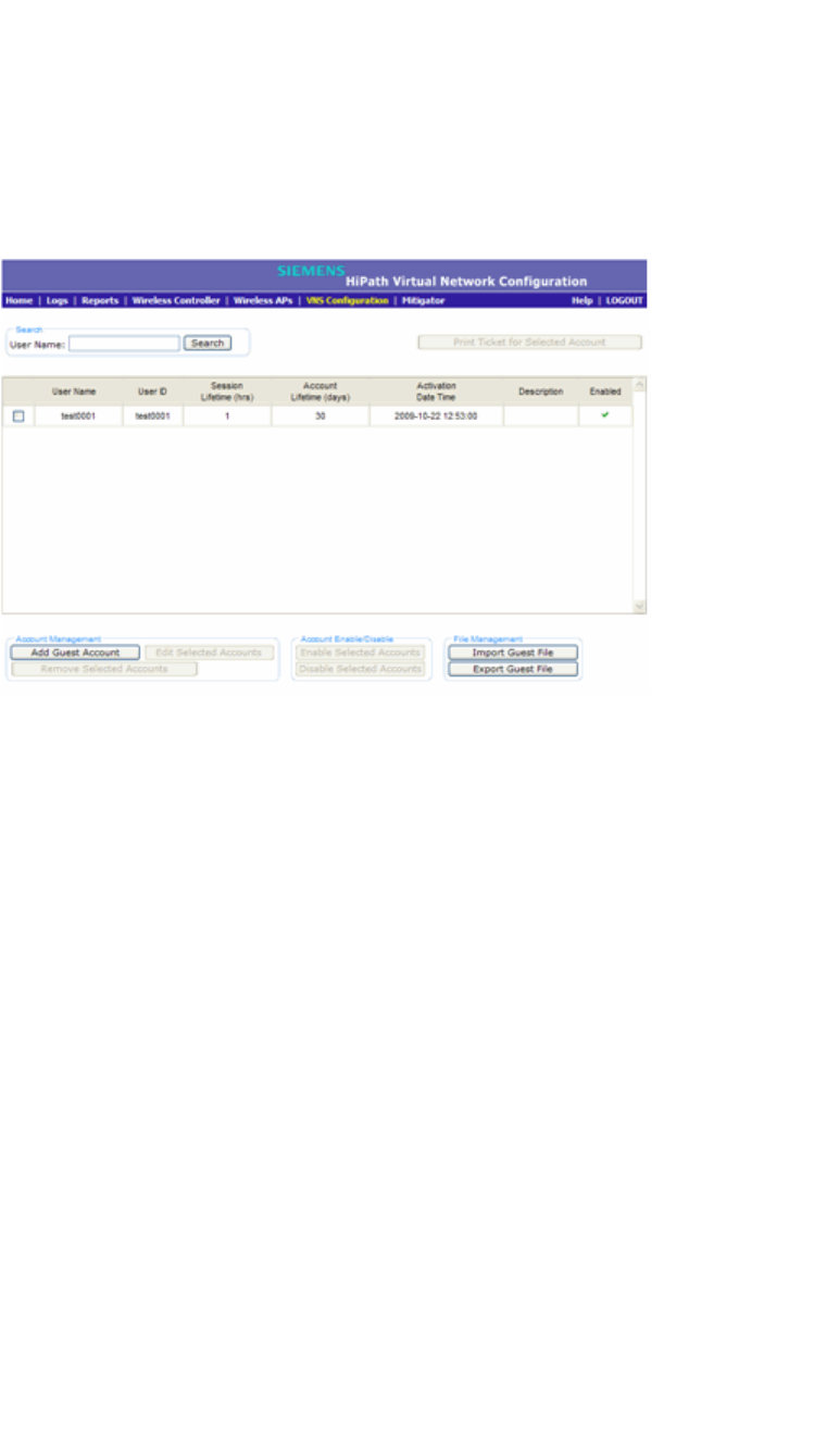
Performing system administration
hwc_ongoing.fm
Defining HiPath Wireless Assistant administrators and login groups
9034530-02, March 2010
456 HiPath Wireless Controller, Access Points and Convergence Software V7.11, User Guide
A GuestPortal administrator is assigned to the GuestPortal Manager login group
and can only create and manage guest user accounts — a GuestPortal
administrator cannot access any other area of the HiPath Wireless Assistant. For
more information, see Section 12.2, “Defining HiPath Wireless Assistant
administrators and login groups”, on page 453.
From the GuestPortal Guest Administration page of the HiPath Wireless
Assistant, you can add, edit, configure, and import and export guest accounts.
12.2.1.1 Adding new guest accounts
To add a new guest account:
1. Do one of the following:
•If you have GuestPortal Manager rights, log onto the HiPath Wireless
Controller.
•If you have full administrator rights:
a) From the main menu, click Virtual Network Configuration. The
Virtual Network Configuration screen is displayed.
b) In the left pane, expand the WLAN Services pane, click the
dedicated WLAN Service that provides the temporary guest network
services. The WLAN Services configuration window for that service
displays.
c) Click the Auth & Acct tab, and then click Configure. The Settings
screen is displayed.
d) In the GuestPortal section, click Manage Guest Users.
The GuestPortal Guest Administration screen is displayed.
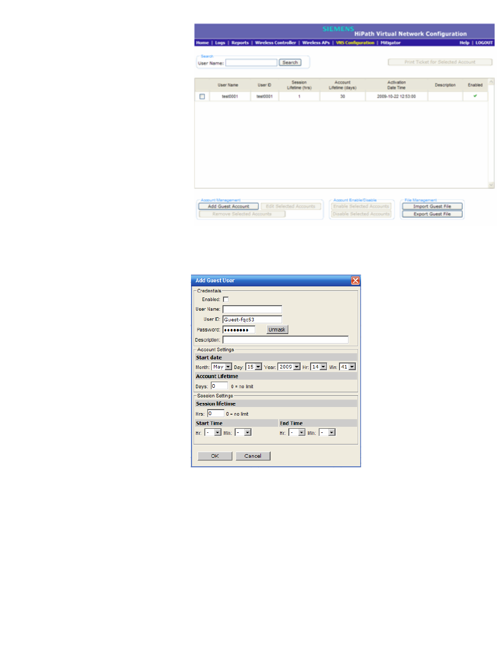
hwc_ongoing.fm
Performing system administration
Defining HiPath Wireless Assistant administrators and login groups
9034530-02, March 2010
HiPath Wireless Controller, Access Points and Convergence Software V7.11, User Guide 457
2. In the Account Management section, click Add Guest Account. The Add
Guest User screen is displayed.
3. To enable the new guest account, select the Enabled checkbox. For more
information, see Section 12.2.1.2, “Enabling or disabling guest accounts”, on
page 458.
4. In the Credentials section, do the following:
• User Name – Type a user name for the person who will use this guest
account.
•User ID – Type a user ID for the person who will use this guest account.
The default user ID can be edited.
• Password – Type a password for the person who will use this guest
account. The default password can be edited.

Performing system administration
hwc_ongoing.fm
Defining HiPath Wireless Assistant administrators and login groups
9034530-02, March 2010
458 HiPath Wireless Controller, Access Points and Convergence Software V7.11, User Guide
Toggle between Mask/Unmask to hide or see the password.
• Description – Type a brief description for the new guest account.
5. In the Account Settings section, do the following:
• Start date – Specify the start date and time for the new guest account.
• Account lifetime – Specify the account lifetime, in days, for the new
guest account. The default 0 value does not limit the account lifetime.
6. In the Session Settings section, do the following:
• Session lifetime – Specify a session lifetime, in hours, for the new guest
account. The default 0 value does not limit a session lifetime. The session
lifetime is the allowed cumulative total in hours spent on the network
during the account lifetime.
• Start Time – Specify a start time for the session for the new guest
account.
• End Time – Specify an end time for the session for the new guest
account.
7. To save your changes, click OK.
12.2.1.2 Enabling or disabling guest accounts
A guest account must be enabled in order for a wireless device user to use the
guest account to obtain guest network services.
When a guest account is disabled, it remains in the database. A disabled guest
account cannot provide access to the network.
To enable or disable guest accounts:
1. Do one of the following:
•If you have GuestPortal Manager rights, log onto the HiPath Wireless
Controller.
•If you have full administrator rights:
a) From the main menu, click Virtual Network Configuration. The
Virtual Network Configuration screen is displayed.
b) In the left pane, expand the WLAN Services pane, click the
dedicated WLAN Service that provides the temporary guest network
services. The WLAN Services configuration window for that service
displays.
c) Click the Auth & Acct tab, and then click Configure. The Settings
screen is displayed.
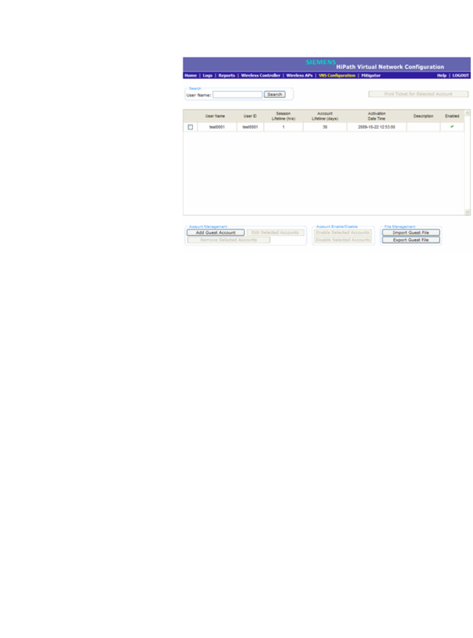
hwc_ongoing.fm
Performing system administration
Defining HiPath Wireless Assistant administrators and login groups
9034530-02, March 2010
HiPath Wireless Controller, Access Points and Convergence Software V7.11, User Guide 459
d) In the GuestPortal section, click Manage Guest Users.
The GuestPortal Guest Administration screen is displayed.
2. In the guest account list, select the checkbox next to the user name of the
guest account that you want to enable or disable.
3. In the Account Enable/Disable section, click Enable Selected Accounts or
Disable Selected Accounts accordingly. A dialog is displayed requesting
you to confirm your selection.
4. Click Ok. A confirmation message is displayed in the GuestPortal Guest
Administration screen footer.
12.2.1.3 Editing guest accounts
An already existing guest account can be edited.
To edit a guest account:
1. Do one of the following:
•If you have GuestPortal Manager rights, log onto the HiPath Wireless
Controller.
•If you have full administrator rights:
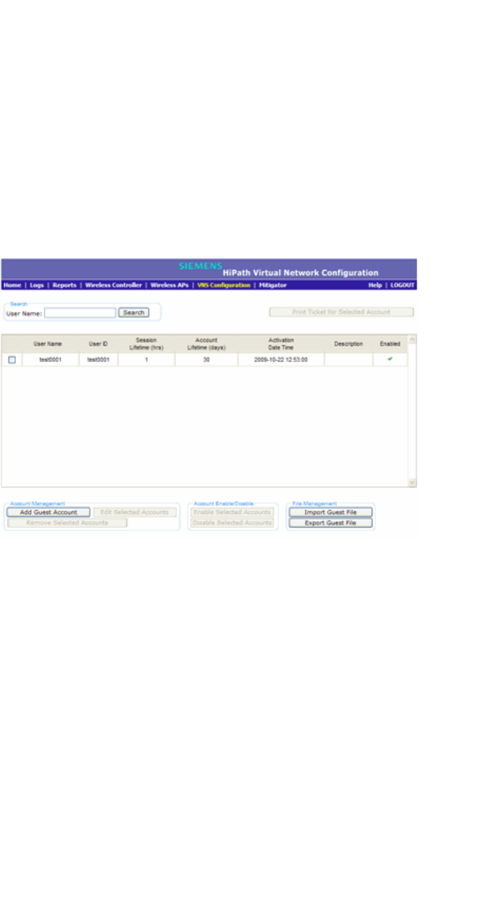
Performing system administration
hwc_ongoing.fm
Defining HiPath Wireless Assistant administrators and login groups
9034530-02, March 2010
460 HiPath Wireless Controller, Access Points and Convergence Software V7.11, User Guide
a) From the main menu, click Virtual Network Configuration. The
Virtual Network Configuration screen is displayed.
b) In the left pane, expand the WLAN Services pane, click the
dedicated WLAN Service that provides the temporary guest network
services. The WLAN Services configuration window for that service
displays.
c) Click the Auth & Acct tab, and then click Configure. The Settings
screen is displayed.
d) In the GuestPortal section, click Manage Guest Users.
The GuestPortal Guest Administration screen is displayed.
2. In the guest account list, select the checkbox next to the user name of the
guest account that you want to edit.
3. In the Account Management section, click Edit Selected Accounts. The
Edit Guest User screen is displayed.
4. Edit the guest account accordingly. For more information on guest account
properties, see Section 12.2.1.1, “Adding new guest accounts”, on page 456.
5. To save your changes, click OK. A confirmation message is displayed in the
GuestPortal Guest Administration screen footer.
12.2.1.4 Removing guest accounts
An already existing guest account can be removed from the database.
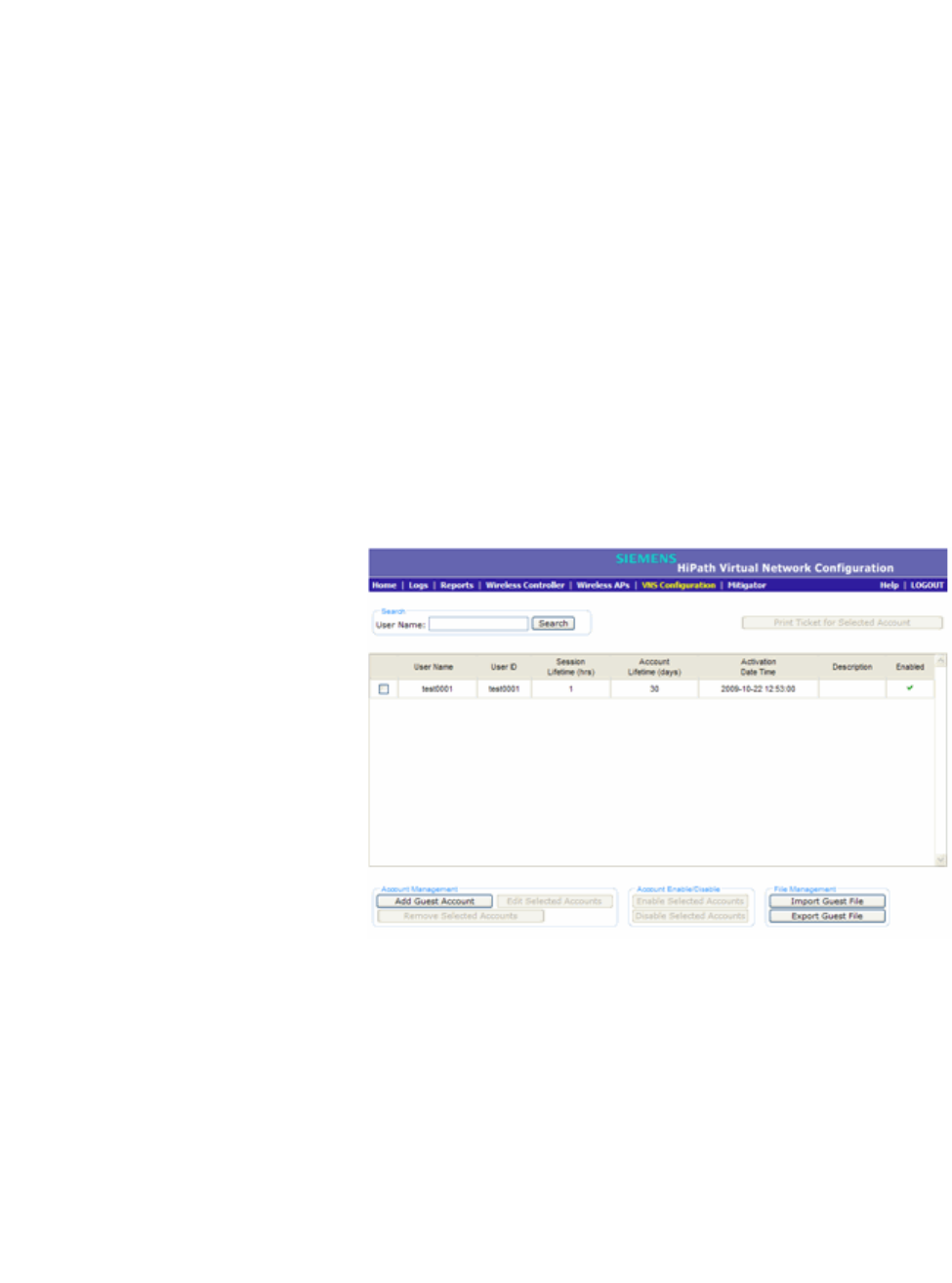
hwc_ongoing.fm
Performing system administration
Defining HiPath Wireless Assistant administrators and login groups
9034530-02, March 2010
HiPath Wireless Controller, Access Points and Convergence Software V7.11, User Guide 461
To remove a guest account:
1. Do one of the following:
•If you have GuestPortal Manager rights, log onto the HiPath Wireless
Controller.
•If you have full administrator rights:
a) From the main menu, click Virtual Network Configuration. The
Virtual Network Configuration screen is displayed.
b) In the left pane, expand the WLAN Services pane, click the
dedicated WLAN Service that provides the temporary guest network
services. The WLAN Services configuration window for that service
displays.
c) Click the Auth & Acct tab, and then click Configure. The Settings
screen is displayed.
d) In the GuestPortal section, click Manage Guest Users.
The GuestPortal Guest Administration screen is displayed.
2. In the guest account list, select the checkbox next to the user name of the
guest account that you want to remove.
3. In the Account Management section, click Remove Selected Accounts. A
dialog is displayed requesting you to confirm your removal.
4. Click OK. A confirmation message is displayed in the GuestPortal Guest
Administration screen footer.

Performing system administration
hwc_ongoing.fm
Defining HiPath Wireless Assistant administrators and login groups
9034530-02, March 2010
462 HiPath Wireless Controller, Access Points and Convergence Software V7.11, User Guide
12.2.1.5 Importing and exporting a guest file
To help administrators manage large numbers of guest accounts, you can import
and export .csv (comma separated value) guest files for the HiPath Wireless
Controller.
The following describes the column values of the .csv guest file.
To export a guest file
1. Do one of the following:
•If you have GuestPortal Manager rights, log onto the HiPath Wireless
Controller.
•If you have full administrator rights:
a) From the main menu, click Virtual Network Configuration. The
Virtual Network Configuration screen is displayed.
b) In the left pane, expand the WLAN Services pane, click the
dedicated WLAN Service that provides the temporary guest network
services. The WLAN Services configuration window for that service
displays.
c) Click the Auth & Acct tab, and then click Configure. The Settings
screen is displayed.
d) In the GuestPortal section, click Manage Guest Users.
The GuestPortal Guest Administration screen is displayed.
Column Value
AUser ID
B User name
C Password
D Description
E Account activation date
F Account lifetime, measured in days
G Session lifetime, measured in hours
H Is the account enabled (1) or disabled (0)
I Time of day, start time
J Time of day, duration
K Total time of the session lifetime that has been
used, measured in minutes
L Is the guest user account synchronized on a
secondary HiPath Wireless Controller in an
availability pair, yes (1) no (0)
Table 37 Guest account import and export .csv file values
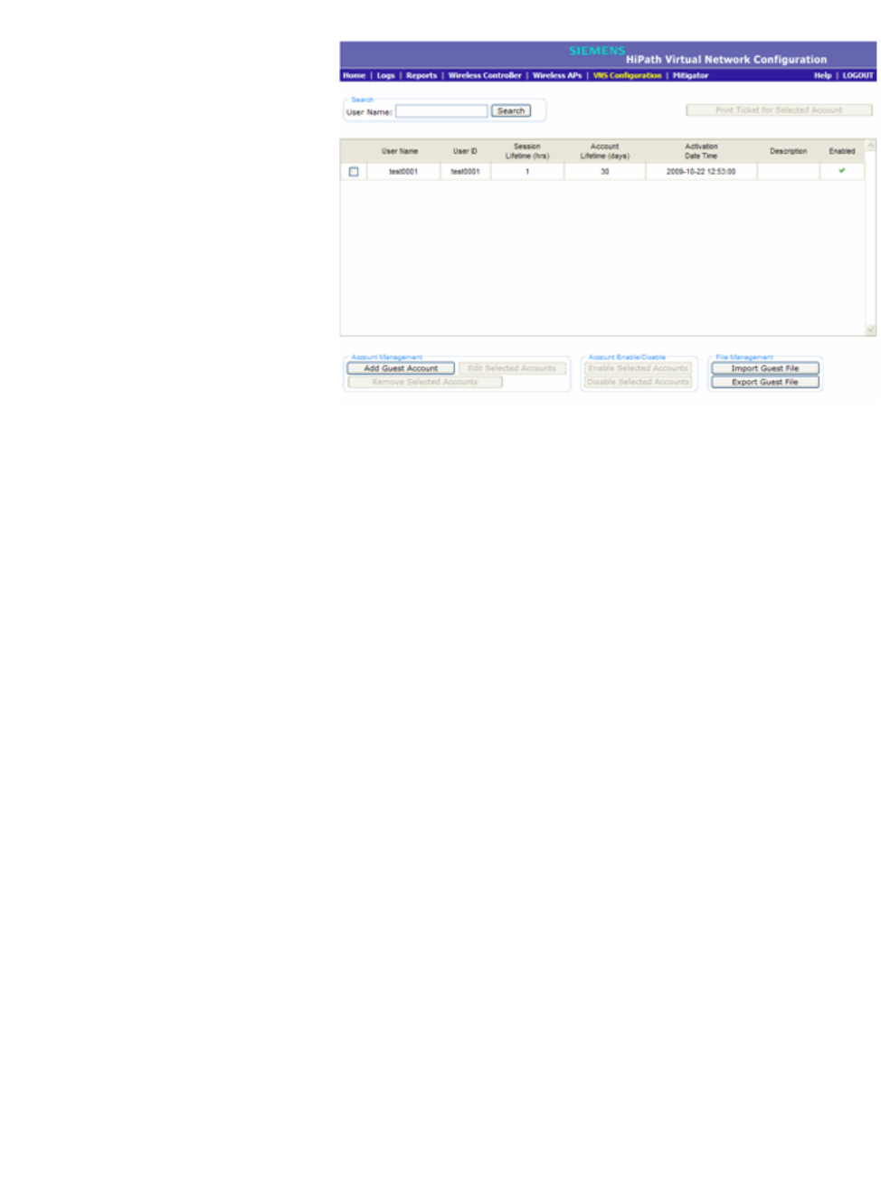
hwc_ongoing.fm
Performing system administration
Defining HiPath Wireless Assistant administrators and login groups
9034530-02, March 2010
HiPath Wireless Controller, Access Points and Convergence Software V7.11, User Guide 463
2. In the File Management section, click Export Guest File. A File Download
dialog is displayed.
3. Click Save. The Save As dialog is displayed.
4. Name the guest file, and then navigate to the location where you want to save
the file. By default, the exported guest file is named exportguest.csv.
5. Click Save. The File Download dialog is displayed as the file is exported.
6. Click Close. A confirmation message is displayed in the GuestPortal Guest
Administration screen footer.
To import a guest file
1. Do one of the following:
•If you have GuestPortal Manager rights, log onto the HiPath Wireless
Controller.
•If you have full administrator rights:
a) From the main menu, click Virtual Network Configuration. The
Virtual Network Configuration screen is displayed.
b) In the left pane, expand the WLAN Services pane, click the
dedicated WLAN Service that provides the temporary guest network
services. The WLAN Services configuration window for that service
displays.
c) Click the Auth & Acct tab, and then click Configure. The Settings
screen is displayed.
d) In the GuestPortal section, click Manage Guest Users.
The GuestPortal Guest Administration screen is displayed.
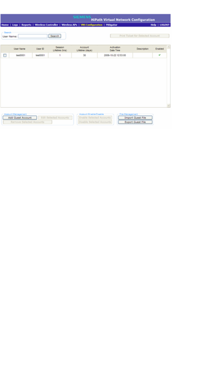
Performing system administration
hwc_ongoing.fm
Defining HiPath Wireless Assistant administrators and login groups
9034530-02, March 2010
464 HiPath Wireless Controller, Access Points and Convergence Software V7.11, User Guide
2. In the File Management section, click Import Guest File. The Import Guest
File dialog is displayed.
3. Click Browse to navigate to the location of the .csv guest file that you want to
import, and then click Open.
4. Click Import. The file is imported and a confirmation message is displayed in
the Import Guest File dialog.
5. Click Close.
12.2.1.6 Viewing and printing a GuestPortal account ticket
You can view and print a GuestPortal account ticket from the GuestPortal Guest
Administration screen. A GuestPortal account ticket is a print-ready form that
displays the guest account information, system requirements, and instructions on
how to log on to the guest account.
The HiPath Wireless Controller is shipped with a default template for the
GuestPortal account ticket. The template is an html page that is augmented with
system placeholders that display information about the user.
You can also upload a custom GuestPortal ticket template for the HiPath Wireless
Controller. To upload a custom GuestPortal ticket template you need full
administrator access rights on the HiPath Wireless Controller. The filename of a
custom GuestPortal ticket template must be .html. For more information, see
Section 12.2.1.7, “Working with the GuestPortal ticket page”, on page 466.

hwc_ongoing.fm
Performing system administration
Defining HiPath Wireless Assistant administrators and login groups
9034530-02, March 2010
HiPath Wireless Controller, Access Points and Convergence Software V7.11, User Guide 465
To view print a GuestPortal account ticket:
1. Do one of the following:
•If you have GuestPortal Manager rights, log onto the HiPath Wireless
Controller.
•If you have full administrator rights:
a) From the main menu, click Virtual Network Configuration. The
Virtual Network Configuration screen is displayed.
b) In the left pane, expand the WLAN Services pane, click the
dedicated WLAN Service that provides the temporary guest network
services. The WLAN Services configuration window for that service
displays.
c) Click the Auth & Acct tab, and then click Configure. The Settings
screen is displayed.
d) In the GuestPortal section, click Manage Guest Users.
The GuestPortal Guest Administration screen is displayed.
2. In the guest account list, select the checkbox next to the user name whose
guest account ticket you want to print a ticket, and then click Print Ticket for
Selected Account. The GuestPortal ticket is displayed.
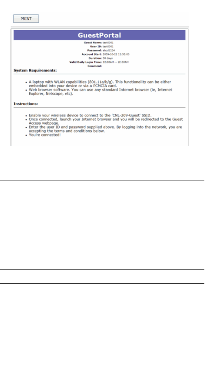
Performing system administration
hwc_ongoing.fm
Defining HiPath Wireless Assistant administrators and login groups
9034530-02, March 2010
466 HiPath Wireless Controller, Access Points and Convergence Software V7.11, User Guide
3. Click Print. The Print dialog is displayed.
4. Click Print.
Note: The default GuestPortal ticket page uses placeholder tags. For more
information, see Appendix E, “Default GuestPortal source code”
12.2.1.7 Working with the GuestPortal ticket page
Working with the GuestPortal ticket page can include activating a GuestPortal
ticket page, uploading a customized GuestPortal ticket page to the HiPath
Wireless Controller, and deleting a customized GuestPortal ticket page.
Note: The default GuestPortal ticket page cannot be deleted.
To work with the GuestPortal account ticket page, you need full administrator
rights. You can work with the guest account ticket page from the Settings screen.
A guest account ticket is a print-ready form that displays the guest account
information, system requirements, and instructions on how to log on to the guest
account.

hwc_ongoing.fm
Performing system administration
Defining HiPath Wireless Assistant administrators and login groups
9034530-02, March 2010
HiPath Wireless Controller, Access Points and Convergence Software V7.11, User Guide 467
Working with a custom GuestPortal ticket page
A customized GuestPortal ticket page can be uploaded to the HiPath Wireless
Controller. When designing your customized GuestPortal ticket page, be sure to
use the guest account information placeholder tags that are depicted in the
default GuestPortal ticket page. For more information, see Appendix E, “Default
GuestPortal source code”.
To activate a GuestPortal ticket page:
1. From the main menu, click Virtual Network Configuration. The Virtual
Network Configuration screen is displayed.
2. In the left pane, expand the WLAN Services pane, click the dedicated WLAN
Service that provides the temporary guest network services. The WLAN
Services configuration window for that service displays.
3. Click the Auth & Acct tab, and then click Configure. The Settings screen is
displayed.
4. In the GuestPortal section, click Configure Ticket Page. The Ticket
Settings dialog is displayed.
5. In the Active Template list, click the GuestPortal ticket page you want to
activate, and then click Apply.
This list includes all GuestPortal ticket pages that have been uploaded to the
HiPath Wireless Controller.
To upload a custom GuestPortal ticket page:
1. On the Ticket Settings dialog, click Browse. The Choose file dialog is
displayed.
2. Navigate to the .html GuestPortal ticket page file that you want to upload to
the HiPath Wireless Controller, and then click Open. The file name is
displayed in the Upload Template box.
3. Click Apply. The file is uploaded to the HiPath Wireless Controller.
The Active Template list includes all GuestPortal ticket pages that have
been uploaded to the HiPath Wireless Controller.
To delete a custom GuestPortal ticket page:
1. On the Ticket Settings dialog, in the Active Template list, click the
GuestPortal ticket page you want to delete, and then click Delete. A dialog
prompts you to confirm you want to delete the GuestPortal ticket page.
2. To delete the file, click OK, and then click Apply.,
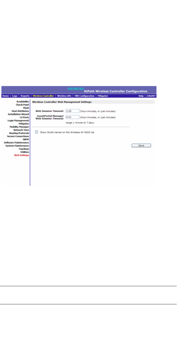
Performing system administration
hwc_ongoing.fm
Configuring Web session timeouts
9034530-02, March 2010
468 HiPath Wireless Controller, Access Points and Convergence Software V7.11, User Guide
12.3 Configuring Web session timeouts
You can configure the time period to allow Web sessions to remain inactive
before timing out.
To configure Web session timeouts:
1. From the main menu, click Wireless Controller Configuration. The
Wireless Controller Configuration screen is displayed.
2. In the left pane, click Web Settings The Wireless Controller Web
Management Settings screen is displayed.
3. In the Web Session Timeout box, type the time period to allow the Web
session to remain inactive before it times out. This can be entered as
hour:minutes, or as minutes. The range is 1 minute to 168 hours.
4. In the GuestPortal Manager Web Session Timeout box, type the time
period to allow the GuestPortal Web session to remain inactive before it times
out. This can be entered as hour:minutes, or as minutes. The range is 1
minute to 168 hours.
5. Select the Show WLAN names on the Wireless AP SSID list checkbox to
allow the names of the WLAN services to appear in the SSID list for Wireless
APs.
6. To save your settings, click Save.
Note: Screens that auto-refresh will time-out unless a manual action takes
place prior to the end of the timeout period.

hwc_glossary.fm
9034530-02, March 2010
HiPath Wireless Controller, Access Points and Convergence Software V7.11, User Guide 469
Glossary
Networking terms and abbreviations
13 Glossary
13.1 Networking terms and abbreviations
Term Explanation
AAA Authentication, Authorization and Accounting. A system in IP-based networking to control
what computer resources users have access to and to keep track of the activity of users over
a network.
Access Point (AP) A wireless LAN transceiver or ‘base station’ that can connect a wired LAN to one or many
wireless devices.
Ad-hoc mode An 802.11 networking framework in which devices or stations communicate directly with each
other, without the use of an access point (AP). (Compare Infrastructure Mode)
AES Advanced Encryption Standard (AES) is an algorithm for encryption that works at multiple
network layers simultaneously. As a block cipher, AES encrypts data in fixed-size blocks of
128 bits. AES was created by the National Institute of Standards and Technology (NIST). AES
is a privacy transform for IPSec and Internet Key Exchange (IKE). AES has a variable key
length - the algorithm can specify a 128-bit key (the default), a 192-bit key, or a 256-bit key.
For the WPA2/802.11i implementation of AES, a 128 bit key length is used. AES encryption
includes 4 stages that make up one round. Each round is then iterated 10, 12 or 14 times
depending upon the bit-key size. For the WPA2/802.11i implementation of AES, each round
is iterated 10 times.
AES-CCMP AES uses the Counter-Mode/CBC-MAC Protocol (CCMP). CCM is a new mode of operation
for a block cipher that enables a single key to be used for both encryption and authentication.
The two underlying modes employed in CCM include Counter mode (CTR) that achieves data
encryption and Cipher Block Chaining Message Authentication Code (CBC-MAC) to provide
data integrity.
ARP Address Resolution Protocol. A protocol used to obtain the physical addresses (such as MAC
addresses) of hardware units in a network environment. A host obtains such a physical
address by broadcasting an ARP request, which contains the IP address of the target
hardware unit. If the request finds a unit with that IP address, the unit replies with its physical
hardware address.
Association A connection between a wireless device and an Access Point.
asynchronous Asynchronous transmission mode (ATM). A start/stop transmission in which each character is
preceded by a start signal and followed by one or more stop signals. A variable time interval
can exist between characters. ATM is the preferred technology for the transfer of images.
BSS Basic Service Set. A wireless topology consisting of one Access Point connected to a wired
network and a set of wireless devices. Also called an infrastructure network. See also IBSS.
Captive Portal A browser-based authentication mechanism that forces unauthenticated users to a Web page.
Sometimes called a ‘reverse firewall’.

Glossary
hwc_glossary.fm
Networking terms and abbreviations
9034530-02, March 2010
470 HiPath Wireless Controller, Access Points and Convergence Software V7.11, User Guide
CDR Call Data (Detail) Record
In Internet telephony, a call detail record is a data record that contains information related to
a telephone call, such as the origination and destination addresses of the call, the time the call
started and ended, the duration of the call, the time of day the call was made and any toll
charges that were added through the network or charges for operator services, among other
details of the call.
In essence, call accounting is a database application that processes call data from your switch
(PBX, iPBX, or key system) via a CDR (call detail record) or SMDR (station message detail
record) port. The call data record details your system's incoming and outgoing calls by
thresholds, including time of call, duration of call, dialing extension, and number dialed. Call
data is stored in a PC database
CHAP Challenge-Handshake Authentication Protocol. One of the two main authentication protocols
used to verify a user's name and password for PPP Internet connections. CHAP is more
secure than PAP because it performs a three-way handshake during the initial link
establishment between the home and remote machines. It can also repeat the authentication
anytime after the link has been established.
CLI Command Line Interface.
Collision Two Ethernet packets attempting to use the medium simultaneously. Ethernet is a shared
media, so there are rules for sending packets of data to avoid conflicts and protect data
integrity. When two nodes at different locations attempt to send data at the same time, a
collision will result. Segmenting the network with bridges or switches is one way of reducing
collisions in an overcrowded network.
Datagram A datagram is ”a self-contained, independent entity of data carrying sufficient information to
be routed from the source to the destination computer without reliance on earlier exchanges
between this source and destination computer and the transporting network." (RFC1594). The
term has been generally replaced by the term packet. Datagrams or packets are the message
units that the Internet Protocol deals with and that the Internet transports.
dBm An abbreviation for the power ratio in decibels (dB) of the measured power
referenced to one milliwatt.
Decapsulation See tunnelling.
Device Server A specialized, network-based hardware device designed to perform a single or specialized set
of server functions. Print servers, terminal servers, remote access servers and network time
servers are examples of device servers.
DHCP Dynamic Host Configuration Protocol. A protocol for assigning dynamic IP addresses to
devices on a network. With dynamic addressing, a device can have a different IP address
every time it connects to the network. In some systems, the device's IP address can even
change while it is still connected. DHCP also supports a mix of static and dynamic IP
addresses.
DHCP consists of two components: a protocol for delivering host-specific configuration
parameters from a DHCP server to a host and a mechanism for allocation of network
addresses to hosts. (IETF RFC1531.)
Option 78 specifies the location of one or more SLP Directory Agents. Option 79 specifies the
list of scopes that a SLP Agent is configured to use.(RFC2610 - DHCP Options for Service
Location Protocol)
Term Explanation

hwc_glossary.fm
Glossary
Networking terms and abbreviations
9034530-02, March 2010
HiPath Wireless Controller, Access Points and Convergence Software V7.11, User Guide 471
Directory Agent (DA) A method of organizing and locating the resources (such as printers, disk drives, databases,
e-mail directories, and schedulers) in a network. Using SLP, networking applications can
discover the existence, location and configuration of networked devices.
With Service Location Protocol, client applications are 'User Agents' and services are
advertised by 'Service Agents'. The User Agent issues a multicast 'Service Request' (SrvRqst)
on behalf of the client application, specifying the services required. The User Agent will
receive a Service Reply (SrvRply) specifying the location of all services in the network which
satisfy the request.
For larger networks, a third entity, called a 'Directory Agent', receives registrations from all
available Service Agents. A User Agent sends a unicast request for services to a Directory
Agent (if there is one) rather than to a Service Agent.
(SLP version 2, RFC2608, updating RFC2165)
Diversity antenna and
receiver
The AP has two antennae. Receive diversity refers to the ability of the AP to provide better
service to a device by receiving from the user on which ever of the two antennae is receiving
the cleanest signal. Transmit diversity refers to the ability of the AP to use its two antenna to
transmit on a specific antenna only, or on a alternate antennae. The antennae are called
diversity antennae because of this capability of the pair.
DNS Domain Name Server
DSSS Direct-Sequence Spread Spectrum. A transmission technology used in Local Area Wireless
Network (LAWN) transmissions where a data signal at the sending station is combined with a
higher data rate bit sequence, or chipping code, that divides the user data according to a
spreading ratio. The chipping code is a redundant bit pattern for each bit that is transmitted,
which increases the signal's resistance to interference. If one or more bits in the pattern are
damaged during transmission, the original data can be recovered due to the redundancy of
the transmission. (Compare FHSS)
DTIM DTIM delivery traffic indication message (in 802.11 standard)
Dynamic WEP The IEEE introduced the concept of user-based authentication using per-user encryption keys
to solve the scalability issues that surrounded static WEP. This resulted in the 802.1X
standard, which makes use of the IETF's Extensible Authentication Protocol (EAP), which was
originally designed for user authentication in dial-up networks. The 802.1X standard
supplemented the EAP protocol with a mechanism to send an encryption key to a Wireless
AP. These encryption keys are used as dynamic WEP keys, allowing traffic to each individual
user to be encrypted using a separate key.
EAP-TLS
EAP-TTLS
EAP-TLS Extensible Authentication Protocol - Transport Layer Security. A general protocol for
authentication that also supports multiple authentication methods, such as token cards,
Kerberos, one-time passwords, certificates, public key authentication and smart cards. IEEE
802.1x specifies how EAP should be encapsulated in LAN frames.
In wireless communications using EAP, a user requests connection to a WLAN through an
access point, which then requests the identity of the user and transmits that identity to an
authentication server such as RADIUS. The server asks the access point for proof of identity,
which the access point gets from the user and then sends back to the server to complete the
authentication.
EAP-TLS provides for certificate-based and mutual authentication of the client and the
network. It relies on client-side and server-side certificates to perform authentication and can
be used to dynamically generate user-based and session-based WEP keys.
EAP-TTLS (Tunneled Transport Layer Security) is an extension of EAP-TLS to provide
certificate-based, mutual authentication of the client and network through an encrypted tunnel,
as well as to generate dynamic, per-user, per-session WEP keys. Unlike EAP-TLS, EAP-
TTLS requires only server-side certificates.
(See also PEAP)
Term Explanation

Glossary
hwc_glossary.fm
Networking terms and abbreviations
9034530-02, March 2010
472 HiPath Wireless Controller, Access Points and Convergence Software V7.11, User Guide
ELA (OPSEC) Event Logging API (Application Program Interface) for OPSEC, a module in Check Point used
to enable third-party applications to log events into the Check Point VPN-1/FireWall-1
management system.
Encapsulation See tunnelling.
ESS Extended Service Set (ESS). Several Basic Service Sets (BSSs) can be joined together to
form one logical WLAN segment, referred to as an extended service set (ESS). The SSID is
used to identify the ESS. (See BSS and SSID.)
FHSS Frequency-Hopping Spread Spectrum. A transmission technology used in Local Area
Wireless Network (LAWN) transmissions where the data signal is modulated with a
narrowband carrier signal that ‘hops’ in a random but predictable sequence from frequency to
frequency as a function of time over a wide band of frequencies. This technique reduces
interference. If synchronized properly, a single logical channel is maintained. (Compare
DSSS)
Fit, thin and fat APs A thin AP architecture uses two components: an access point that is essentially a stripped-
down radio and a centralized management controller that handles the other WLAN system
functions. Wired network switches are also required.
A fit AP, a variation of the thin AP, handles the RF and encryption, while the central
management controller, aware of the wireless users' identities and locations, handles secure
roaming, quality of service, and user authentication. The central management controller also
handles AP configuration and management.
A fat (or thick) AP architecture concentrates all the WLAN intelligence in the access point. The
AP handles the radio frequency (RF) communication, as well as authenticating users,
encrypting communications, secure roaming, WLAN management, and in some cases,
network routing.
FQDN Fully Qualified Domain Name. A ‘friendly’ designation of a computer, of the general form
computer.[subnetwork.].organization.domain. The FQDN names must be translated into an IP
address in order for the resource to be found on a network, usually performed by a Domain
Name Server.
FTM Forwarding Table Manager
FTP File Transfer Protocol
Gateway In the wireless world, an access point with additional software capabilities such as providing
NAT and DHCP. Gateways may also provide VPN support, roaming, firewalls, various levels
of security, etc.
Gigabit Ethernet The high data rate of the Ethernet standard, supporting data rates of 1 gigabit (1,000
megabits) per second.
GUI Graphical User Interface
Heartbeat message A heartbeat message is a UDP data packet used to monitor a data connection, polling to see
if the connection is still alive.
In general terms, a heartbeat is a signal emitted at regular intervals by software to
demonstrate that it is still alive. In networking, a heartbeat is the signal emitted by a Level 2
Ethernet transceiver at the end of every packet to show that the collision-detection circuit is
still connected.
Host (1) A computer (usually containing data) that is accessed by a user working on a remote
terminal, connected by modems and telephone lines.
(2) A computer that is connected to a TCP/IP network, including the Internet. Each host has
a unique IP address.
Term Explanation

hwc_glossary.fm
Glossary
Networking terms and abbreviations
9034530-02, March 2010
HiPath Wireless Controller, Access Points and Convergence Software V7.11, User Guide 473
HTTP Hypertext Transfer Protocol is the set of rules for transferring files (text, graphic images,
sound, video, and other multimedia files) on the World Wide Web. A Web browser makes use
of HTTP. HTTP is an application protocol that runs on top of the TCP/IP suite of protocols.
(RFC2616: Hypertext Transfer Protocol -- HTTP/1.1)
HTTPS Hypertext Transfer Protocol over Secure Socket Layer, or HTTP over SSL, is a Web protocol
that encrypts and decrypts user page requests as well as the pages that are returned by the
Web server. HTTPS uses Secure Socket Layer (SSL) as a sublayer under its regular HTTP
application layering. (HTTPS uses port 443 instead of HTTP port 80 in its interactions with the
lower layer, TCP/IP.) SSL uses a 40-bit key size for the RC4 stream encryption algorithm,
which is considered an adequate degree of encryption for commercial exchange.
IBSS Independent Basic Service Set. See BSS. An IBSS is the 802.11 term for an adhoc network.
See adhoc network.
ICMP Internet Control Message Protocol, an extension to the Internet Protocol (IP) defined by
RFC792. ICMP supports packets containing error, control, and informational messages. The
PING command, for example, uses ICMP to test an Internet connection.
ICV ICV (Integrity Check Value) is a 4-byte code appended in standard WEP to the 802.11
message. Enhanced WPA inserts an 8-byte MIC just before the ICV. (See WPA and MIC)
IE Internet Explorer.
IEEE Institute of Electrical and Electronics Engineers, a technical professional association, involved
in standards activities.
IETF Internet Engineering Task Force, the main standards organization for the Internet.
Infrastructure Mode An 802.11 networking framework in which devices communicate with each other by first going
through an Access Point (AP). In infrastructure mode, wireless devices can communicate with
each other or can communicate with a wired network. (See ad-hoc mode and BSS.)
Internet or IP telephony IP or Internet telephony are communications, such as voice, facsimile, voice-messaging
applications, that are transported over the Internet, rather than the public switched telephone
network (PSTN). IP telephony is the two-way transmission of audio over a packet-switched IP
network (TCP/IP network).
An Internet telephone call has two steps: (1) converting the analog voice signal to digital
format, (2) translating the signal into Internet protocol (IP) packets for transmission over the
Internet. At the receiving end, the steps are reversed. Over the public Internet, voice quality
varies considerably. Protocols that support Quality of Service (QoS) are being implemented
to improve this.
IP Internet Protocol is the method or protocol by which data is sent from one computer to another
on the Internet. Each computer (host) on the Internet has at least one IP address that uniquely
identifies it. Internet Protocol specifies the format of packets, also called datagrams, and the
addressing scheme. Most networks combine IP with a higher-level protocol called
Transmission Control Protocol (TCP), which establishes a virtual connection between a
destination and a source.
IPC Interprocess Communication. A capability supported by some operating systems that allows
one process to communicate with another process. The processes can be running on the
same computer or on different computers connected through a network.
Term Explanation

Glossary
hwc_glossary.fm
Networking terms and abbreviations
9034530-02, March 2010
474 HiPath Wireless Controller, Access Points and Convergence Software V7.11, User Guide
IPsec
IPsec-ESP
IPsec-AH
Internet Protocol security (IPSec)
Internet Protocol security Encapsulating Security Payload (IPsec-ESP). The encapsulating
security payload (ESP) encapsulates its data, enabling it to protect data that follows in the
datagram.Internet Protocol security Authentication Header (IPsec-AH). AH protects the parts
of the IP datagram that can be predicted by the sender as it will be received by the
receiver.IPsec is a set of protocols developed by the IETF to support secure exchange of
packets at the IP layer. IPsec has been deployed widely to implement Virtual Private Networks
(VPNs). IPsec supports two encryption modes: Transport and Tunnel. Transport mode
encrypts only the data portion (payload) of each packet, but leaves the header untouched. The
more secure Tunnel mode encrypts both the header and the payload. On the receiving side,
an IPSec-compliant device decrypts each packet. For IPsec to work, the sending and
receiving devices must share a public key. This is accomplished through a protocol known as
Internet Security Association and Key Management Protocol/Oakley (ISAKMP/Oakley), which
allows the receiver to obtain a public key and authenticate the sender using digital certificates.
isochronous Isochronous data is data (such as voice or video) that requires a constant transmission rate,
where data must be delivered within certain time constraints. For example, multimedia
streams require an isochronous transport mechanism to ensure that data is delivered as fast
as it is displayed and to ensure that the audio is synchronized with the video. Compare:
asynchronous processes in which data streams can be broken by random intervals, and
synchronous processes, in which data streams can be delivered only at specific intervals.
ISP Internet Service Provider.
IV IV (Initialization Vector), part of the standard WEP encryption mechanism that concatenates
a shared secret key with a randomly generated 24-bit initialization vector. WPA with TKIP uses
48-bit IVs, an enhancement that significantly increases the difficulty in cracking the encryption.
(See WPA and TKIP)
LAN Local Area Network.
License installation
LSA Link State Advertisements received by the currently running OSPF process. The LSAs
describe the local state of a router or network, including the state of the router's interfaces and
adjacencies. See also OSPF.
MAC Media Access Control layer. One of two sublayers that make up the Data Link Layer of the
OSI model. The MAC layer is responsible for moving data packets to and from one Network
Interface Card (NIC) to another across a shared channel.
MAC address Media Access Control address. A hardware address that uniquely identifies each node of a
network.
MIB Management Information Base is a formal description of a set of network objects that can be
managed using the Simple Network Management Protocol (SNMP). The format of the MIB is
defined as part of the SNMP. A MIB is a collection of definitions defining the properties of a
managed object within a device. Every managed device keeps a database of values for each
of the definitions written in the MIB. Definition of the MIB conforms to RFC1155 (Structure of
Management Information).
MIC Message Integrity Check or Code (MIC), also called ‘Michael’, is part of WPA and TKIP. The
MIC is an additional 8-byte code inserted before the standard 4-byte integrity check value
(ICV) that is appended in by standard WEP to the 802.11 message. This greatly increases the
difficulty in carrying out forgery attacks.
Both integrity check mechanisms are calculated by the receiver and compared against the
values sent by the sender in the frame. If the values match, there is assurance that the
message has not been tampered with. (See WPA, TKIP and ICV).
Term Explanation

hwc_glossary.fm
Glossary
Networking terms and abbreviations
9034530-02, March 2010
HiPath Wireless Controller, Access Points and Convergence Software V7.11, User Guide 475
MTU Maximum Transmission Unit. The largest packet size, measured in bytes, that a network
interface is configured to accept. Any messages larger than the MTU are divided into smaller
packets before being sent.
MU Mobile Unit, a wireless device such as a PC laptop.
multicast, broadcast, unicast Multicast: transmitting a single message to a select group of recipients. Broadcast: sending a
message to everyone connected to a network. Unicast: communication over a network
between a single sender and a single receiver.
NAS Network Access Server, a server responsible for passing information to designated RADIUS
servers and then acting on the response returned. A NAS-Identifier is a RADIUS attribute
identifying the NAS server. (RFC2138)
NAT Network Address Translator. A network capability that enables a group of computers to
dynamically share a single incoming IP address. NAT takes the single incoming IP address
and creates new IP address for each client computer on the network.
Netmask In administering Internet sites, a netmask is a string of 0's and 1's that mask or screen out the
network part of an IP address, so that only the host computer part of the address remains. A
frequently-used netmask is 255.255.255.0, used for a Class C subnet (one with up to 255 host
computers). The ".0" in the "255.255.255.0" netmask allows the specific host computer
address to be visible.
NIC Network Interface Card. An expansion board in a computer that connects the computer to a
network.
NMS Network Management System. The system responsible for managing a network or a portion
of a network. The NMS talks to network management agents, which reside in the managed
nodes.
NTP Network Time Protocol, an Internet standard protocol (built on top of TCP/IP) that assures
accurate synchronization to the millisecond of computer clock times in a network of
computers. Based on UTC, NTP synchronizes client workstation clocks to the U.S. Naval
Observatory Master Clocks in Washington, DC and Colorado Springs CO. Running as a
continuous background client program on a computer, NTP sends periodic time requests to
servers, obtaining server time stamps and using them to adjust the client's clock. (RFC1305)
OFDM Orthogonal frequency division multiplexing, a method of digital modulation in which a signal is
split into several narrowband channels at different frequencies. OFDM is similar to
conventional frequency division multiplexing (FDM). The difference lies in the way in which the
signals are modulated and demodulated. Priority is given to minimizing the interference, or
crosstalk, among the channels and symbols comprising the data stream. Less importance is
placed on perfecting individual channels.
OFDM is used in European digital audio broadcast services. It is also used in wireless local
area networks.
OID Object Identifier.
OPSEC OPSEC (Open Platform for Security) is a security alliance program created by Check Point to
enable an open industry-wide framework for interoperability of security products and
applications. Products carrying the ‘Secured by Check Point’ seal have been tested to
guarantee integration and interoperability.
OS Operating system.
OSI Open System Interconnection. An ISO standard for worldwide communications that defines a
networking framework for implementing protocols in seven layers. Control is passed from one
layer to the next, starting at the application layer in one station, down through the presentation,
session, transport, network, data link layer to the physical layer at the bottom, over the channel
to the next station and back up the hierarchy.
Term Explanation

Glossary
hwc_glossary.fm
Networking terms and abbreviations
9034530-02, March 2010
476 HiPath Wireless Controller, Access Points and Convergence Software V7.11, User Guide
OSI Layer 2 At the Data Link layer (OSI Layer 2), data packets are encoded and decoded into bits. The
data link layer has two sublayers:
•the Logical Link Control (LLC) layer controls frame synchronization, flow control and error
checking
•The Media Access Control (MAC) layer controls how a computer on the network gains
access to the data and permission to transmit it.
OSI Layer 3 The Network layer (OSI Layer 3) provides switching and routing technologies, creating logical
paths, known as virtual circuits, for transmitting data from node to node. Routing and
forwarding are functions of this layer, as well as addressing, internetworking, error handling,
congestion control and packet sequencing.
OSPF Open Shortest Path First, an interior gateway routing protocol developed for IP networks
based on the shortest path first or link-state algorithm. Routers use link-state algorithms to
send routing information to all nodes in an internetwork by calculating the shortest path to
each node based on a topography of the Internet constructed by each node. Each router
sends that portion of the routing table (keeps track of routes to particular network destinations)
that describes the state of its own links, and it also sends the complete routing structure
(topography). Using OSPF, a host that obtains a change to a routing table or detects a change
in the network immediately multicasts the information to all other hosts in the network so that
all will have the same routing table information. The host using OSPF sends only the part that
has changed, and only when a change has taken place. (RFC2328)
OUI Organizationally Unique Identifier (used in MAC addressing).
Packet The unit of data that is routed between an origin and a destination on the Internet or any other
packet-switched network. When any file is sent from one place to another on the Internet, the
Transmission Control Protocol (TCP) layer of TCP/IP divides the file into packets. Each packet
is separately numbered and includes the Internet address of the destination. The individual
packets for a given file may travel different routes through the Internet. When they have all
arrived, they are reassembled into the original file (by the TCP layer at the receiving end).
PAP Password Authentication Protocol is the most basic form of authentication, in which a user's
name and password are transmitted over a network and compared to a table of name-
password pairs. Typically, the passwords stored in the table are encrypted. (See CHAP).
PDU Protocol Data Unit. A data object exchanged by protocol machines (such as management
stations, SMUX peers, and SNMP agents) and consisting of both protocol control information
and user data. PDU is sometimes used as a synonym for “packet''.
PEAP PEAP (Protected Extensible Authentication Protocol) is an IETF draft standard to authenticate
wireless LAN clients without requiring them to have certificates. In PEAP authentication, first
the user authenticates the authentication server, then the authentication server authenticates
the user. If the first phase is successful, the user is then authenticated over the SSL tunnel
created in phase one using EAP-Generic Token Card (EAP-GTC) or Microsoft Challenged
Handshake Protocol Version 2 (MSCHAP V2). (See also EAP-TLS).
PHP server Hypertext Preprocessor
PKI Public Key Infrastructure
PoE Power over Ethernet. The Power over Ethernet standard (802.3af) defines how power can be
provided to network devices over existing Ethernet connection, eliminating the need for
additional external power supplies.
POST Power On Self Test, a diagnostic testing sequence performed by a computer to determine if
its hardware elements are present and powered on. If so, the computer begins its boot
sequence.
Term Explanation

hwc_glossary.fm
Glossary
Networking terms and abbreviations
9034530-02, March 2010
HiPath Wireless Controller, Access Points and Convergence Software V7.11, User Guide 477
push-to-talk (PTT) The push-to-talk (PTT) is feature on wireless telephones that allows them to operate like a
walkie-talkie in a group, instead of standard telephone operation. The PTT feature requires
that the network be configured to allow multicast traffic.
A PTT call is initiated by selecting a channel and pressing the ‘talk’ key on the wireless
telephone. All wireless telephones on the same network that are monitoring the channel will
hear the transmission. On a PTT call you hold the button to talk and release it to listen.
QoS Quality of Service. A term for a number of techniques that intelligently match the needs of
specific applications to the network resources available, using such technologies as Frame
Relay, Asynchronous Transfer Mode (ATM), Ethernet and 802.1 networks, SONET, and
IP-routed networks. QoS features provide better network service by supporting dedicated
bandwidth, improving loss characteristics, avoiding and managing network congestion,
shaping network traffic, setting traffic priorities across the network.
Quality-of-Service (QoS): A set of service requirements to be met by the network while
transporting a flow. (RFC2386)
RADIUS Remote Authentication Dial-In User Service. An authentication and accounting system that
checks User Name and Password and authorizes access to a network. The RADIUS
specification is maintained by a working group of the IETF (RFC2865 RADIUS, RFC2866
RADIUS Accounting, RFC2868 RADIUS Attributes for Tunnel Protocol Support).
RF Radio Frequency, a frequency in the electromagnetic spectrum associated with radio wave
propagation. When an RF current is supplied to an antenna, an electromagnetic field is
created that can propagate through space. These frequencies in the electromagnetic
spectrum range from Ultra-low frequency (ULF) -- 0-3 Hz to Extremely high frequency (EHF)
-- 30GHz - 300 GHz. The middle ranges are: Low frequency (LF) -- 30 kHz - 300 kHz, Medium
frequency (MF) -- 300 kHz - 3 MHz, High frequency (HF) -- 3MHz - 30 MHz, Very high
frequency (VHF) -- 30 MHz - 300 MHz, Ultra-high frequency (UHF)-- 300MHz - 3 GHz.
RFC Request for Comments, a series of notes about the Internet, submitted to the Internet
Engineering Task Force (IETF) and designated by an RFC number, that may evolve into an
Internet standard. The RFCs are catalogued and maintained on the IETF RFC website:
www.ietf.org/rfc.html.
Roaming In 802.11, roaming occurs when a wireless device (a station) moves from one Access Point
to another (or BSS to another) in the same Extended Service Set (ESS) -identified by its SSID.
RP-SMA Reverse Polarity-Subminiature version A, a type of connector used with wireless antennas
RSN Robust Security Network. A new standard within IEEE 802.11 to provide security and privacy
mechanisms. The RSN (and related TSN) both specify IEEE 802.1x authentication with
Extensible Authentication Protocol (EAP).
RSSI RSSI received signal strength indication (in 802.11 standard)
RTS / CTS RTS request to send, CTS clear to send (in 802.11 standard)
Segment In Ethernet networks, a section of a network that is bounded by bridges, routers or switches.
Dividing a LAN segment into multiple smaller segments is one of the most common ways of
increasing available bandwidth on the LAN.
Term Explanation

Glossary
hwc_glossary.fm
Networking terms and abbreviations
9034530-02, March 2010
478 HiPath Wireless Controller, Access Points and Convergence Software V7.11, User Guide
SLP Service Location Protocol. A method of organizing and locating the resources (such as
printers, disk drives, databases, e-mail directories, and schedulers) in a network. Using SLP,
networking applications can discover the existence, location and configuration of networked
devices.
With Service Location Protocol, client applications are 'User Agents' and services are
advertised by 'Service Agents'. The User Agent issues a multicast 'Service Request' (SrvRqst)
on behalf of the client application, specifying the services required. The User Agent will
receive a Service Reply (SrvRply) specifying the location of all services in the network which
satisfy the request.
For larger networks, a third entity, called a 'Directory Agent', receives registrations from all
available Service Agents. A User Agent sends a unicast request for services to a Directory
Agent (if there is one) rather than to a Service Agent.
(SLP version 2, RFC2608, updating RFC2165)
SMI Structure of Management Information. A hierarchical tree structure for information that
underlies Management Information Bases (MIBs), and is used by the SNMP protocol. Defined
in RFC1155 and RFC1442 (SNMPv2).
SMT (802.11) Station ManagemenT. The object class in the 802.11 MIB that provides the necessary support
at the station to manage the processes in the station such that the station may work
cooperatively as a part of an IEEE 802.11 network. The four branches of the 802.11 MIB are:
•dot11smt - objects related to station management and local configuration
•dot11mac - objects that report/configure on the status of various MAC parameters
•dot11res - Objects that describe available resources
•dot11phy - Objects that report on various physical items.
SNMP Simple Network Management Protocol. A set of protocols for managing complex networks.
SNMP works by sending messages, called protocol data units (PDUs), to different parts of a
network. SNMP-compliant devices, called agents, store data about themselves in
Management Information Bases (MIBs) and return this data to the SNMP requesters.
SNMP includes a limited set of management commands and responses. The management
system issues Get, GetNext and Set messages to retrieve single or multiple object variables
or to establish the value of a single variable. The managed agent sends a Response message
to complete the Get, GetNext or Set.
SNMP trap An event notification sent by the SNMP managed agent to the management system to identify
the occurrence of conditions (such as a threshold that exceeds a predetermined value).
SSH Secure Shell, sometimes known as Secure Socket Shell, is a Unix-based command interface
and protocol for securely getting access to a remote computer. SSH is a suite of three utilities
- slogin, ssh, and scp - secure versions of the earlier UNIX utilities, rlogin, rsh, and rcp. With
SSH commands, both ends of the client/server connection are authenticated using a digital
certificate, and passwords are protected by being encrypted.
SSID Service Set Identifier. A 32-character unique identifier attached to the header of packets sent
over a Wireless LAN that acts as a password when a wireless device tries to connect to the
Basic Service Set (BSS). Several BSSs can be joined together to form one logical WLAN
segment, referred to as an extended service set (ESS). The SSID is used to identify the ESS.
In 802.11 networks, each Access Point advertises its presence several times per second by
broadcasting beacon frames that carry the ESS name (SSID). Stations discover APs by
listening for beacons, or by sending probe frames to search for an AP with a desired SSID.
When the station locates an appropriately-named Access Point, it sends an associate request
frame containing the desired SSID. The AP replies with an associate response frame, also
containing the SSID.
Some APs can be configured to send a zero-length broadcast SSID in beacon frames instead
of sending their actual SSID. The AP must return its actual SSID in the probe response.
Term Explanation

hwc_glossary.fm
Glossary
Networking terms and abbreviations
9034530-02, March 2010
HiPath Wireless Controller, Access Points and Convergence Software V7.11, User Guide 479
SSL Secure Sockets Layer. A protocol developed by Netscape for transmitting private documents
via the Internet. SSL works by using a public key to encrypt data that's transferred over the
SSL connection. URLs that require an SSL connection start with https: instead of http.
SSL uses a program layer located between the Internet's Hypertext Transfer Protocol (HTTP)
and Transport Control Protocol (TCP) layers. The ‘sockets’ part of the term refers to the
sockets method of passing data back and forth between a client and a server program in a
network or between program layers in the same computer. SSL uses the public-and-private
key encryption system from RSA, which also includes the use of a digital certificate.
SSL has recently been succeeded by Transport Layer Security (TLS), which is based on SSL.
Subnet mask (See netmask)
Subnets Portions of networks that share the same common address format. A subnet in a TCP/IP
network uses the same first three sets of numbers (such as 198.63.45.xxx), leaving the fourth
set to identify devices on the subnet. A subnet can be used to increase the bandwidth on the
network by breaking the network up into segments.
SVP SpectraLink Voice Protocol, a protocol developed by SpectraLink to be implemented on
access points in order to facilitate voice prioritization over an 802.11 wireless LAN that will
carry voice packets from SpectraLink wireless telephones.
Switch In networks, a device that filters and forwards packets between LAN segments. Switches
operate at the data link layer (layer 2) and sometimes the network layer (layer 3) of the OSI
Reference Model and therefore support any packet protocol. LANs that use switches to join
segments are called switched LANs or, in the case of Ethernet networks, switched Ethernet
LANs.
syslog A protocol used for the transmission of event notification messages across networks,
originally developed on the University of California Berkeley Software Distribution (BSD) TCP/
IP system implementations, and now embedded in many other operating systems and
networked devices. A device generates a messages, a relay receives and forwards the
messages, and a collector (a syslog server) receives the messages without relaying them.
Syslog uses the user datagram protocol (UDP) as its underlying transport layer mechanism.
The UDP port that has been assigned to syslog is 514. (RFC3164)
TCP / IP Transmission Control Protocol. TCP, together with IP (Internet Protocol), is the basic
communication language or protocol of the Internet. Transmission Control Protocol manages
the assembling of a message or file into smaller packets that are transmitted over the Internet
and received by a TCP layer that reassembles the packets into the original message. Internet
Protocol handles the address part of each packet so that it gets to the right destination.
TCP/IP uses the client/server model of communication in which a computer user (a client)
requests and is provided a service (such as sending a Web page) by another computer (a
server) in the network.
TFTP Trivial File Transfer Protocol. An Internet software utility for transferring files that is simpler to
use than the File Transfer Protocol (FTP) but less capable. It is used where user
authentication and directory visibility are not required. TFTP uses the User Datagram Protocol
(UDP) rather than the Transmission Control Protocol (TCP). TFTP is described formally in
Request for Comments (RFC) 1350.
TKIP Temporal Key Integrity Protocol (TKIP) is an enhancement to the WEP encryption technique
that uses a set of algorithms that rotates the session keys. TKIPs’ enhanced encryption
includes a per-packet key mixing function, a message integrity check (MIC), an extended
initialization vector (IV) with sequencing rules, and a re-keying mechanism. The encryption
keys are changed (rekeyed) automatically and authenticated between devices after the rekey
interval (either a specified period of time, or after a specified number of packets has been
transmitted).
TLS Transport Layer Security. (See EAP, Extensible Authentication Protocol)
Term Explanation

Glossary
hwc_glossary.fm
Networking terms and abbreviations
9034530-02, March 2010
480 HiPath Wireless Controller, Access Points and Convergence Software V7.11, User Guide
ToS / DSCP ToS (Type of Service) / DSCP (Diffserv Codepoint). The ToS/DSCP box contained in the IP
header of a frame is used by applications to indicate the priority and Quality of Service (QoS)
for each frame. The level of service is determined by a set of service parameters which
provide a three way trade-off between low-delay, high-reliability, and high-throughput. The use
of service parameters may increase the cost of service.
TSN Transition Security Network. A subset of Robust Security Network (RSN), which provides an
enhanced security solution for legacy hardware. The Wi-Fi Alliance has adopted a solution
called Wireless Protected Access (WPA), based on TSN. RSN and TSN both specify IEEE
802.1x authentication with Extensible Authentication Protocol (EAP).
Tunnelling Tunnelling (or encapsulation) is a technology that enables one network to send its data via
another network's connections. Tunnelling works by encapsulating packets of a network
protocol within packets carried by the second network. The receiving device then
decapsulates the packets and forwards them in their original format.
UDP User Datagram Protocol. A connectionless protocol that, like TCP, runs on top of IP networks.
Unlike TCP/IP, UDP/IP provides very few error recovery services, offering instead a direct way
to send and receive packets over an IP network. It is used primarily for broadcasting
messages over a network.
U-NII Unlicensed National Information Infrastructure. Designated to provide short-range, high-
speed wireless networking communication at low cost, U-NII consists of three frequency
bands of 100 MHz each in the 5 GHz band: 5.15-5.25GHz (for indoor use only), 5.25-5.35 GHz
and 5.725-5.825GHz. The three frequency bands were set aside by the FCC in 1997 initially
to help schools connect to the Internet without the need for hard wiring. U-NII devices do not
require licensing.
URL Uniform Resource Locator. the unique global address of resources or files on the World Wide
Web. The URL contains the name of the protocol to be used to access the file resource, the
IP address or the domain name of the computer where the resource is located, and a
pathname -- a hierarchical description that specifies the location of a file in that computer.
VLAN Virtual Local Area Network. A network of computers that behave as if they are connected to
the same wire when they may be physically located on different segments of a LAN. VLANs
are configured through software rather than hardware, which makes them extremely flexible.
When a computer is physically moved to another location, it can stay on the same VLAN
without any hardware reconfiguration.
The standard is defined in IEEE 802.1Q - Virtual LANs, which states that 'IEEE 802 Local Area
Networks (LANs) of all types may be connected together with Media Access Control (MAC)
Bridges, as specified in ISO/IEC 15802-3. This standard defines the operation of Virtual LAN
(VLAN) Bridges that permit the definition, operation and administration of Virtual LAN
topologies within a Bridged LAN infrastructure."
VNS Virtual Network Services (VNS). A Siemens specific technique that provides a means of
mapping wireless networks to a wired topology.
VoIP Voice Over Internet Protocol. An internet telephony technique. With VoIP, a voice
transmission is cut into multiple packets, takes the most efficient path along the Internet and
is reassembled when it reaches the destination.
VPN Virtual Private Network. A private network that is constructed by using public wires to connect
nodes. These systems use encryption and other security mechanisms to ensure that only
authorized users can access the network and that the data cannot be intercepted.
VSA Vendor Specific Attribute, an attribute for a RADIUS server defined by the
manufacturer.(compared to the RADIUS attributes defined in the original RADIUS protocol
RFC2865). A VSA attribute is defined in order that it can be returned from the RADIUS server
in the Access Granted packet to the Radius Client.
Term Explanation

hwc_glossary.fm
Glossary
Networking terms and abbreviations
9034530-02, March 2010
HiPath Wireless Controller, Access Points and Convergence Software V7.11, User Guide 481
Walled Garden A restricted subset of network content that wireless devices can access.
WEP Wired Equivalent Privacy. A security protocol for wireless local area networks (WLANs)
defined in the 802.11b standard. WEP aims to provide security by encrypting data over radio
waves so that it is protected as it is transmitted from one end point to another.
Wi-Fi Wireless fidelity. A term referring to any type of 802.11 network, whether 802.11b, 802.11a,
dual-band, etc. Used in reference to the Wi-Fi Alliance, a nonprofit international association
formed in 1999 to certify interoperability of wireless Local Area Network products based on
IEEE 802.11 specification.
WINS Windows Internet Naming Service. A system that determines the IP address associated with
a particular network computer, called name resolution. WINS supports network client and
server computers running Windows and can provide name resolution for other computers with
special arrangements. WINS supports dynamic addressing (DHCP) by maintaining a
distributed database that is automatically updated with the names of computers currently
available and the IP address assigned to each one.
DNS is an alternative system for name resolution suitable for network computers with fixed IP
addresses.
WLAN Wireless Local Area Network.
WMM Wi-Fi Multimedia (WMM), a Wi-Fi Alliance certified standard that provides multimedia
enhancements for Wi-Fi networks that improve the user experience for audio, video, and voice
applications. This standard is compliant with the IEEE 802.11e Quality of Service (QoS)
extensions for 802.11 networks. WMM provides prioritized media access by shortening the
time between transmitting packets for higher priority traffic. WMM is based on the Enhanced
Distributed Channel Access (EDCA) method.
WPA Wireless Protected Access, or Wi-Fi Protected Access is a security solution adopted by the
Wi-Fi Alliance that adds authentication to WEPs’ basic encryption. For authentication, WPA
specifies IEEE 802.1x authentication with Extensible Authentication Protocol (EAP). For
encryption, WPA uses the Temporal Key Integrity Protocol (TKIP) mechanism, which shares
a starting key between devices, and then changes their encryption key for every packet.
Certificate Authentication (CA) can also be used. Also part of the encryption mechanism are
802.1X for dynamic key distribution and Message Integrity Check (MIC) a.k.a. Michael.
WPA requires that all computers and devices have WPA software.
WPA-PSK Wi-Fi Protected Access with Pre-Shared Key, a special mode of WPA for users without an
enterprise authentication server. Instead, for authentication, a Pre-Shared Key is used. The
PSK is a shared secret (passphrase) that must be entered in both the Wireless AP or router
and the WPA clients.
This preshared key should be a random sequence of characters at least 20 characters long
or hexadecimal digits (numbers 0-9 and letters A-F) at least 24 hexadecimal digits long. After
the initial shared secret, the Temporal Key Integrity Protocol (TKIP) handles the encryption
and automatic rekeying.
Term Explanation

Glossary
hwc_glossary.fm
Controller, Access Points and Convergence Software terms and abbreviations
9034530-02, March 2010
482 HiPath Wireless Controller, Access Points and Convergence Software V7.11, User Guide
13.2 Controller, Access Points and Convergence Software terms and
abbreviations
Term Explanation
CTP CAPWAP Tunnelling Protocol (CTP). The Wireless AP uses a UDP (User Datagram
Protocol) based tunnelling protocol called CAPWAP Tunnelling Protocol (CTP) to
encapsulate the 802.11 packets and forward them to the HiPath Wireless Controller.
The CTP protocol defines a mechanism for the control and provisioning of Wireless APs
(CAPWAP) through centralized access controllers. In addition, it provides a mechanism
providing the option to tunnel the mobile client data between the access point and the access
controller.
DRM (dynamic radio/RF
management)
Dynamic Radio Management (DRM) functionality of the HiPath Wireless Controller is used
to help establish the optimum radio configuration for your Wireless APs. DRM is enabled by
default. The HiPath Wireless Controller’s DRM:
•Adjusts power levels to balance coverage if another Wireless AP, which is assigned to the
same SSID and is on the same channel, is added to or leaves the network.
•Allows wireless clients to be moved to another Wireless AP if the load is too high.
•Scans automatically for a channel, using a channel selection algorithm.
•Avoids other WLANs by reducing transmit power whenever other Wireless APs with the
same channel, but different SSIDs are detected.
The DRM feature is comprised of two functions:
•Auto Channel Selection (ACS) – ACS provides an easy way to optimize channel
arrangement based on the current situation in the field. ACS provides an optimal solution
only if it is triggered on all Wireless APs in a deployment. Triggering ACS on a single
Wireless AP or on a subset of Wireless APs provides a useful but suboptimal solution.
Also, ACS only relies on the information observed at the time it is triggered. Once a
Wireless AP has selected a channel, it will remain operating on that channel until the user
changes the channel or triggers ACS.
•Auto Tx Power Control (ATPC) – ATPC guarantees your LAN a stable RF environment by
automatically adapting transmission power signals according to the coverage provided by
the Wireless APs. ATPC can be either enabled or disabled.
HiPath Wireless Controller The HiPath Wireless Controller is a rack-mountable network device designed to be
integrated into an existing wired Local Area Network (LAN). It provides centralized control
over all access points (both Wireless APs and third-party access points) and manages the
network assignment of wireless device clients associating through access points.
Langley Langley is a Controller, Access Points and Convergence Software term for the inter-process
messaging infrastructure on the HiPath Wireless Controller.
Mitigator The Mitigator is a mechanism that assists in the detection of rogue access points. The feature
has three components: (1) a radio frequency (RF) scanning task that runs on the Wireless
AP, (2) an application called the Data Collector on the HiPath Wireless Controller that
receives and manages the RF scan messages sent by the Wireless AP, (3) an Analysis
Engine on the HiPath Wireless Controller that processes the scan data.
Mobility manager (and mobility
agent)
The technique in Controller, Access Points and Convergence Software by which multiple
HiPath Wireless Controllers on a network can discover each other and exchange information
about a client session. This enables a wireless device user to roam seamlessly between
different Wireless APs on different HiPath Wireless Controllers, to provide mobility to the
wireless device user.
One HiPath Wireless Controller on the network must be designated as the mobility manager.
All other HiPath Wireless Controllers are designated as mobility agents. Relying on SLP, the
mobility manager registers with the Directory Agent and the mobility agents discover the
location of the mobility manager.

hwc_glossary.fm
Glossary
Controller, Access Points and Convergence Software terms and abbreviations
9034530-02, March 2010
HiPath Wireless Controller, Access Points and Convergence Software V7.11, User Guide 483
Data Collector The Data Collector is an application on the HiPath Wireless Controller that receives and
manages the Radio Frequency (RF) scan messages sent by the Wireless AP. This
application is part of the Mitigator technique, working in conjunction with the scanner
mechanism and the Analysis Engine to assist in detecting rogue access points.
Virtual Network Services
(VNS)
The Virtual Network Services (VNS) technique is Siemens's means of mapping wireless
networks to the topology of an existing wired network. When you set up Virtual Network
Services (VNS) on the HiPath Wireless Controller, you are defining subnets for groups of
wireless users. This VNS definition creates a virtual IP subnet where the HiPath Wireless
Controller acts as a default gateway for wireless devices. This technique enables policies
and authentication to be applied to the groups of wireless users on a VNS, as well as the
collecting of accounting information. When a VNS is set up on the HiPath Wireless Controller,
one or more Wireless APs (by radio) are associated with it. A range of IP addresses is set
aside for the HiPath Wireless Controller's DHCP server to assign to wireless devices.
Wireless AP The Wireless AP is a wireless LAN thin access point (IEEE 802.11) provided with unique
software that allows it to communicate only with a HiPath Wireless Controller. (A thin access
point handles the radio frequency (RF) communication but relies on a controller to handle
WLAN elements such as authentication.) The Wireless AP also provides local processing
such as encryption. The Wireless AP is a dual-band access point, with 802.11a/b/g/n radios.
Term Explanation

Glossary
hwc_glossary.fm
Controller, Access Points and Convergence Software terms and abbreviations
9034530-02, March 2010
484 HiPath Wireless Controller, Access Points and Convergence Software V7.11, User Guide
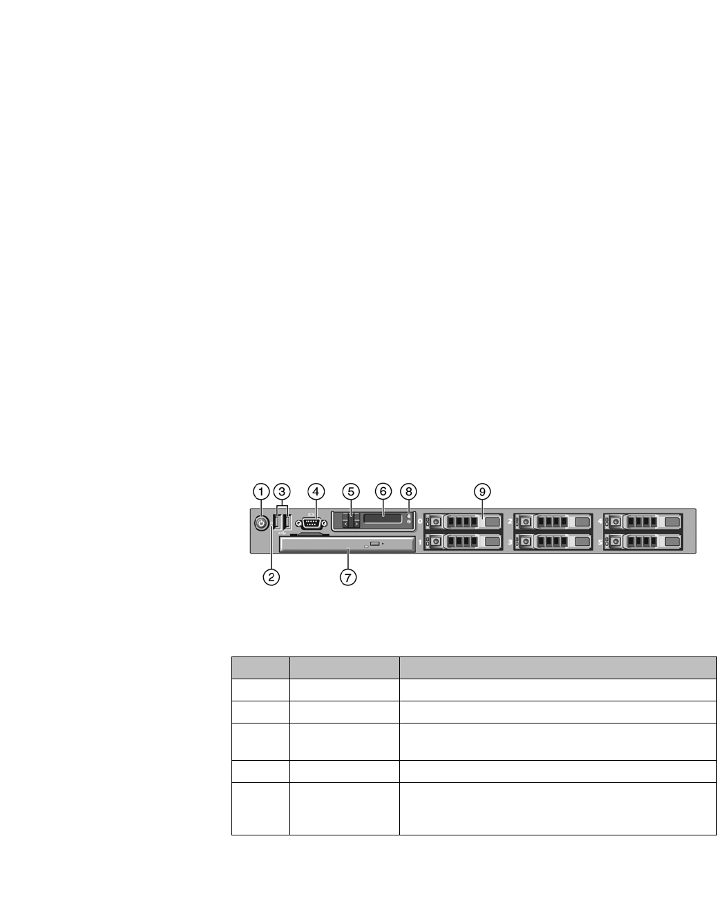
hwc_appendixa.fm
9034530-02, March 2010
HiPath Wireless Controller, Access Points and Convergence Software V7.11, User Guide 485
HiPath Wireless Controller’s physical description
HiPath Wireless Controller C5110
A HiPath Wireless Controller’s physical description
This appendix describes the physical description and LEDs, SSD codes and their
description of the following models of the HiPath Wireless Controller:
•HiPath Wireless Controller C5110
•HiPath Wireless Controller C4110
•HiPath Wireless Controller C2400
•HiPath Wireless Controller C20
•HiPath Wireless Controller C20N
•HiPath Wireless Controller CRBT8210/8110
A.1 HiPath Wireless Controller C5110
A.1.1 Front panel
Figure 29 depicts the front panel features of the HiPath Wireless Controller
C5110. The following table describes the features by callout.
Figure 29 HiPath Wireless Controller C5110 front panel
Call out Feature Function
1 Power-on button Controls the DC power supply output to the system.
2 NMI button Not used in the current release.
3 USB connectors
(2)
Connects USB 2.0-compliant devices to the system. For
more information, see the Note following Figure 29.
3 Video connector Not used in the current release.
5 LCD buttons Controls the LCD display. Two navigation buttons allow
you to scroll left and right through the display. The select
button controls whether the LCD backlight is on or off.
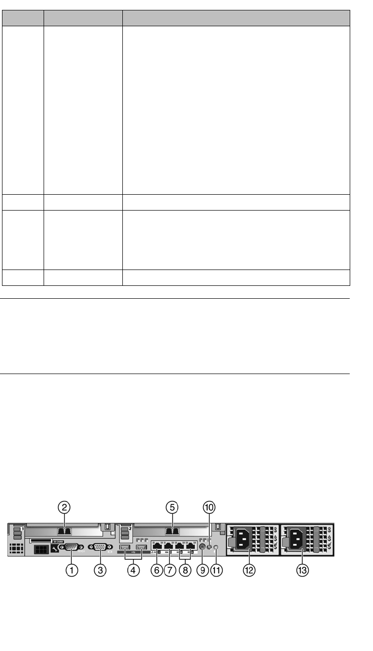
HiPath Wireless Controller’s physical description
hwc_appendixa.fm
HiPath Wireless Controller C5110
9034530-02, March 2010
486 HiPath Wireless Controller, Access Points and Convergence Software V7.11, User Guide
Note: The HiPath Wireless Controller C5110 is equipped with four USB
connectors — two on each front and back panel. However, the controller is
capable of supporting only one USB device at a time, regardless of what USB
connector the device is connected to. If you connect a second USB device while
the first is already connected, the system will return an error.
A.1.2 Back panel
Figure 30 depicts the back panel features of the HiPath Wireless Controller
C5110.
Figure 30 HiPath Wireless Controller C5110 back panel
6 LCD display Provides system ID, status information and system error
messages. The LCD display lights during normal system
operation. Both the systems management software and
the identification buttons located on the front and back of
the system can cause the LCD to flash blue to identify a
particular system. The LCD display lights amber when
the system needs attention due to a problem with power
supplies, fans, system temperature or hard drives.
When the controller is performing a software upgrade
and configuration, the LCD panel will display the word
“Upgrade.”
Note: If the system is connected to AC power and an
error has been detected, the LCD displays amber lights
regardless of whether the system has been powered on.
7 Slot for DVD drive Not used in the current release.
8 System
Identification
button
The identification buttons on the front and back panels
can be used to locate a particular system within a rack.
When one of the buttons is pushed, the blue system
status indicator on the front and back blinks until one of
the buttons is pushed again.
9 Hard drive One 3.5 inch SATA 250 GB drive.
Call out Feature Function

hwc_appendixa.fm
HiPath Wireless Controller’s physical description
HiPath Wireless Controller C4110
9034530-02, March 2010
HiPath Wireless Controller, Access Points and Convergence Software V7.11, User Guide 487
A.2 HiPath Wireless Controller C4110
For information on HiPath Wireless Controller C4110 hardware, see the HiPath
Wireless Controller C4110 Quick Reference at
http://www.enterasys.com/support/manuals.
Callout Feature Function
1 Serial port
connector
Console Port – Used to get into Rescue mode.
2 NIC2 connector Data port, 10 GbE SR-XFP single port NIC - esa1
3 Video connector Not used in the current release
4 USB connectors (2) Connects USB 2.0-compliant devices to the system.
5 10 GbE SR-XFP
single port NIC
connector
Data port - esa2
6 1 GbE RJ45
connector
Management port - Admin
7 1 GbE RJ45
connector
Data port – esa0
8 Not used Not used in the current release.
9 System status
indicator connector
Not used in the current release.
10 System status
indicator
The blue-colored system status indicator blinks to
indicate the location of a particular system within a rack.
The indicator continues to blink until one of the system
identification buttons is pushed again.
11 System
identification button
The identification buttons on the front and back panels
can be used to locate a particular system within a rack.
When one of these buttons is pushed, the blue system
status indicator on the front and back blinks until one of
the buttons is pushed again.
12 AC Power supply 1
(PS1)
AC Power Supply 1 and 2 combine to make a redundant
power supply.
13 AC Power supply 2
(PS2)
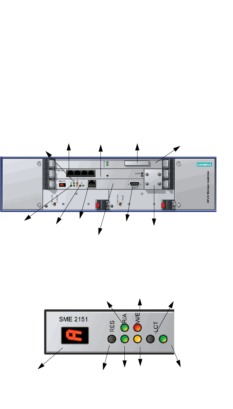
HiPath Wireless Controller’s physical description
hwc_appendixa.fm
HiPath Wireless Controller C2400
9034530-02, March 2010
488 HiPath Wireless Controller, Access Points and Convergence Software V7.11, User Guide
A.3 HiPath Wireless Controller C2400
A.3.1 Front panel
The HiPath Wireless Controller C2400 is composed of the following three cards:
•Media/Persistent Storage Card
•Network Processor Card
•Host HiPath Wireless Controller Card
Figure 31 depicts the front panel features of the HiPath Wireless Controller
C2400.
Figure 31 HiPath Wireless Controller C2400 front panel
The HiPath Wireless Controller C2400 has five LED lights and two switches on
its front panel.
Figure 32 HiPath Wireless Controller’s C2400 LED lights and switches
Reset
switch Console
port
Management
RJ45 port
Media/Persistent
storage card
Network
Processor card
Host Controller
card
Console
adapter
LED
lights
Data
ports
Diagnostic
switch
Compact
Flash slot
Reset
switch
WARNING
LED
ERROR
LED
INT
LED
LCT switch
RUN
LED
ACT
LED
Seven Segment Display

hwc_appendixa.fm
HiPath Wireless Controller’s physical description
HiPath Wireless Controller C2400
9034530-02, March 2010
HiPath Wireless Controller, Access Points and Convergence Software V7.11, User Guide 489
The description of the LED states and switches is provided below:
•Reset Switch – Reboots the system.
•RUN LED – Indicates the CPU’s initialization has completed and the system
is ready to provide application level services.
•ACT LED – Indicates the system’s software is in active running state.
•WARNING/ERROR LEDs – Indicate a problem in the running state of the
system.
•When any of the alarm LEDs is lit, the seven segment display provides
the corresponding code point for the error indication. When the system is
fully active and running, the console displays the letter A as seen in
Figure 32.
•LCT Switch – The LCT button is used during the manufacturing process and
is inactive otherwise.
•INT LED – Not used in the current release.
A.3.2 LED states and Seven Segment Display (SSD)
codes
Firmware initialization:
Active
LED Warning
LED Error
LED SSD Codes Condition
Green 0 The processor has started and the
firmware has taken control.
Green 3 The Host Controller Card has failed to
download Bootloader from Flash.
Green 4 The system is checking firmware
consistency.
Green 5 The system is formatting memory.
Green 6 The system is initializing load device.
Note: If the SSD code is stuck at 6 for
more than a minute, it implies that the
Network Processor Card is installed in
wrong slot.
Green 9 The system is loading subsystem.
Green b The system is starting the operation
system. The system is active.
Table 38 LED states and SSD codes during firmware initialization

HiPath Wireless Controller’s physical description
hwc_appendixa.fm
HiPath Wireless Controller C2400
9034530-02, March 2010
490 HiPath Wireless Controller, Access Points and Convergence Software V7.11, User Guide
Note: Although the Active LED will be lit Green during the firmware initialization,
this LED state is irrelevant to the SSD display or the condition. Ignore the LED
state during the firmware initialization.
Application initialization:
Warning conditions:
Active
LED Warning
LED Error
LED SSD Code Condition
Green 0 Application initialization started.
Green C System configuration in progress.
Green 1 Preparing Forwarding Engine
initialization.
Green 2 Initializing Forwarding Engine.
Green 3 Completing application initialization.
Green A Application initialization complete.
System active.
Green H System halted. Administrator requested
halting of system.
Table 39 LED states and SSD codes during application initialization
Active
LED Warning
LED Error
LED SSD Code Condition
Green Yellow 1 High temperature reached.
Green Yellow 2 Fan unit failure. Rotation counter
indicates zero speed for one of the
lateral trays. May be the result of fan
tray removal.
Green Yellow 3 Power supply failure. Failed to detect
one of the power supplies. May be the
result of the removal of one of the
power supplies.
Green Yellow 4 FDD low sector count (40 backup
sectors remaining).
Green Yellow 5 FDD extremely low sector count (20
backup sectors remaining).
Table 40 LED states and SSD codes during warning conditions
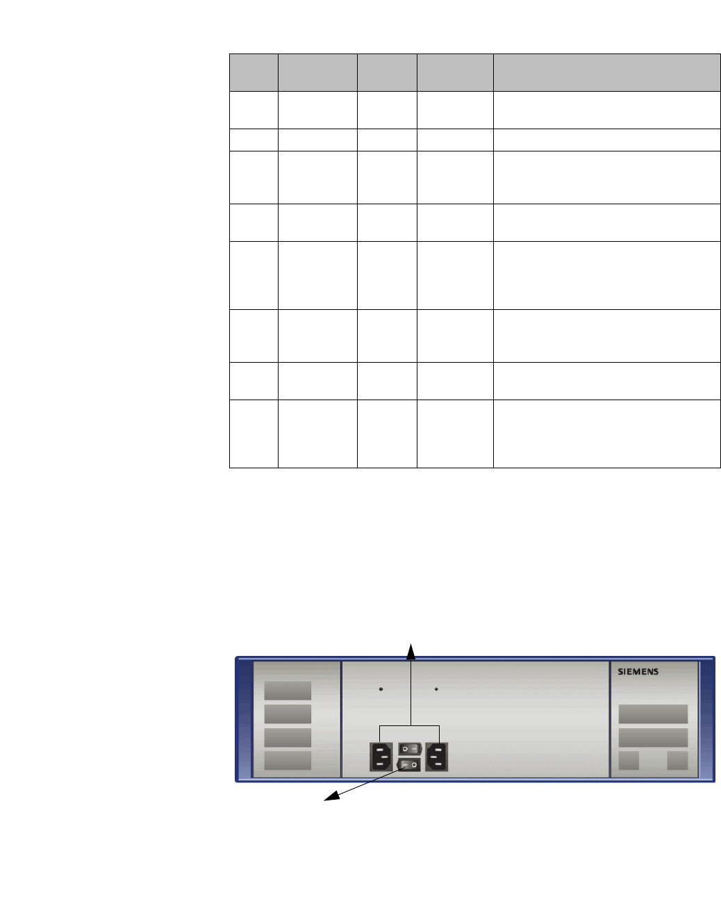
hwc_appendixa.fm
HiPath Wireless Controller’s physical description
HiPath Wireless Controller C2400
9034530-02, March 2010
HiPath Wireless Controller, Access Points and Convergence Software V7.11, User Guide 491
Error conditions:
A.3.3 Back panel
Figure 33 depicts the back panel features of the HiPath Wireless Controller
C2400.
Figure 33 HiPath Wireless Controller C2400 back panel
Active
LED Warning
LED Error
LED SSD Code Condition
Green Red 1 Failed to identify FDD. Possibly due to
removal of FDD card.
Green Red 2 Failed to initialize NPE card.
Green Red 3 Critical threshold reached (95C for
NPE).
The system will reboot.
Green Red 4 Full fan assembly failure (both trays).
The system will reboot.
Green Red 5 Application initialization failure. Startup
manager failed to initialize all the
components of the system.
The system will reboot.
Green Red 6 Lost connectivity with ethernet interface.
Possible failure of NPE card.
The system will reboot.
Green Red 7 MF 1000 card failure. Backup sectors
exhausted.
Green Red 8 NP 4000 card initialization failure.
Firmware self test (BIST) has detected
failure in one or more components
(memory, bus, interconnects).
Table 41 LED states and SSD codes during error conditions
Redundant power supplies
Power switches
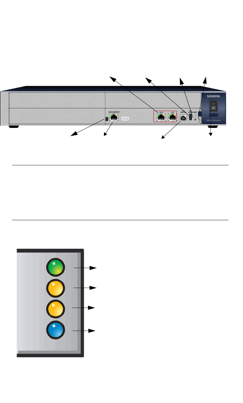
HiPath Wireless Controller’s physical description
hwc_appendixa.fm
HiPath Wireless Controller C20
9034530-02, March 2010
492 HiPath Wireless Controller, Access Points and Convergence Software V7.11, User Guide
A.4 HiPath Wireless Controller C20
A.4.1 Front panel
Figure 34 depicts the front panel features of the HiPath Wireless Controller C20
Figure 34 HiPath Wireless Controller C20 front panel
Note: The hot swap lever is not enabled in the current release. Pulling the hot
swap lever will not affect the normal operation if the HiPath Wireless Controller
C20 is already running. However, if you attempt to reboot the HiPath Wireless
Controller C20 with the hot swap lever pulled out, the controller will fail to reboot.
If you pull the hot swap lever while the HiPath Wireless Controller C20 is in
operation, the Hot Swap LED will light up.
The HiPath Wireless Controller C20 has four lights on its front panel.
Figure 35 HiPath Wireless Controller C20 LED lights
The functional definitions of the HiPath Wireless Controller C20 LEDs are
provided below:
LAN ports
Management
LEDs
USB server
USB control Power switch
Reset button
Hot Swap lever
Activity LED
Status LED
HDD Activity LED
Hot Swap LED

hwc_appendixa.fm
HiPath Wireless Controller’s physical description
HiPath Wireless Controller C20
9034530-02, March 2010
HiPath Wireless Controller, Access Points and Convergence Software V7.11, User Guide 493
•ACTIVITY LED – Indicates the CPU activity, including the amount of traffic
carried to and from the Wireless APs.
•STATUS LED – Indicates the normal state of the HiPath Wireless Controller
as seen by the system’s software. This LED covers all stages of the HiPath
Wireless Controller, ranging from restarting to shutting-down. As long as the
HiPath Wireless Controller is running normally, this LED will remain lit.
Note: When the system configuration is in progress, the Activity and Status
LEDs are set to Amber and blink on a two-second interval.
•HDD Activity LED – Reports Hard Drive Device (HDD) activity.
•Hot Swap LED – Indicates that the hot swap lever on the HiPath Wireless
Controller is pulled out.
A.4.2 LED states
The description of the HiPath Wireless Controller C20 LED status and activity
states is provided below.
•LED 3 – HDD Activity LED – Orange/Amber
•HDD Activity LED is off when HDD is not in use
•HDD Activity LED is on when HDD is in use
•LED 4 – Hot Swap LED – Blue
Status LED Activity LED Condition
Blinking Amber Green Power up (BIOS, POST)
Blinking Amber (2
second rate)
Blinking Amber (2
second rate)
System configuration in progress
Off Green System booting (failed to boot)
Off Green Start up manager: task started
Solid Green Blinking Green Start up manager: task completes startup – all
components active
Solid Amber Blinking Green A component fails to start or needs restarting.
(startup manager task retrying that component)
Green Blinking Red Possible hardware failure (no more retries)
Solid Red Off A component fails (no more retries)
Blinking Red Off System about to reset by watchdog
Solid Red Solid Red System shutdown / halt (requires a manual
reboot)
Table 42 HiPath Wireless Controller C20 LED states and their description
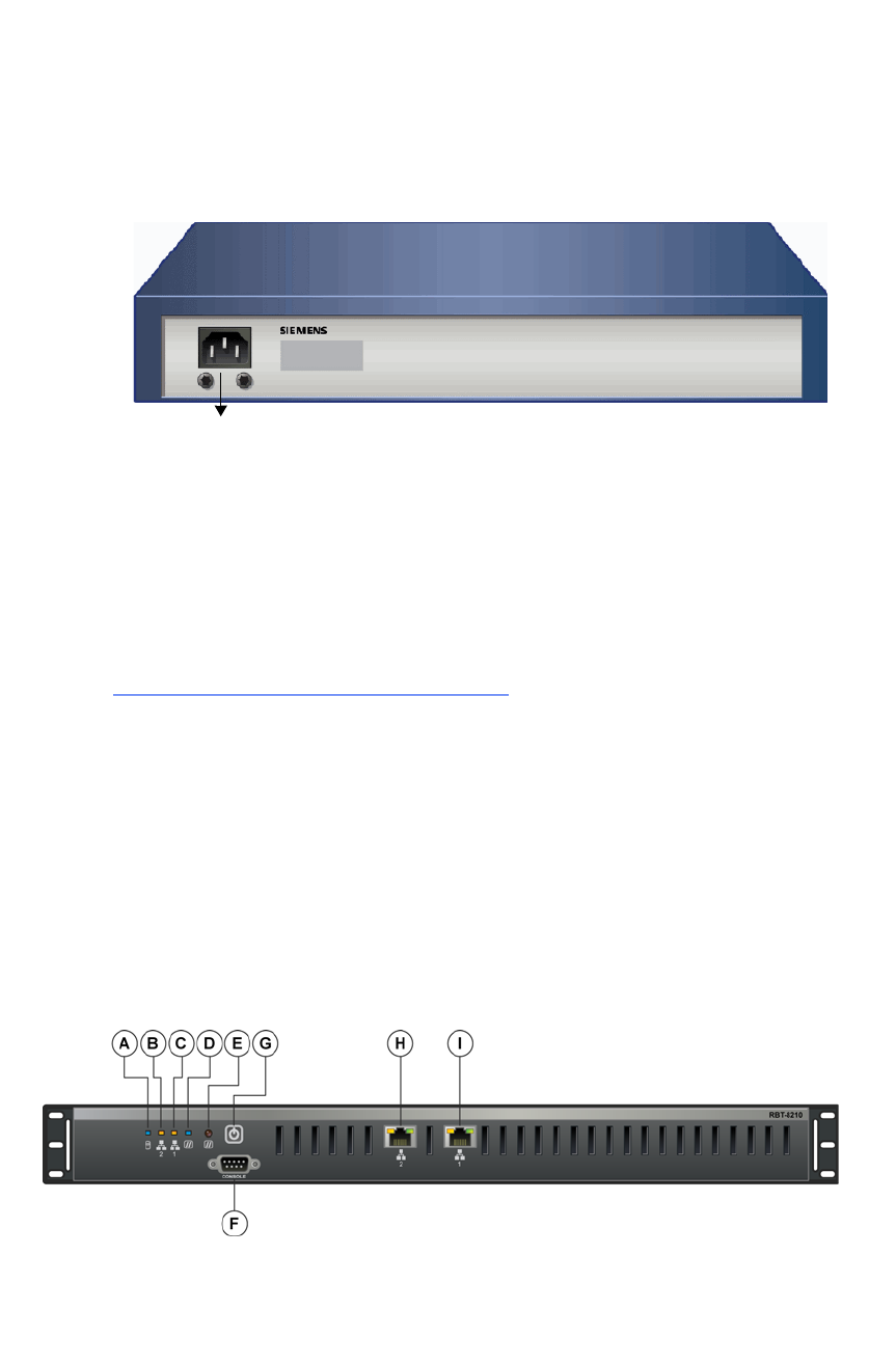
HiPath Wireless Controller’s physical description
hwc_appendixa.fm
HiPath Wireless Controller C20N
9034530-02, March 2010
494 HiPath Wireless Controller, Access Points and Convergence Software V7.11, User Guide
•Solid Blue when the hot swap button is pulled out
A.4.3 Back panel
Figure 36 depicts the back panel features of the HiPath Wireless Controller C20.
Figure 36 HiPath Wireless Controller C20 back panel
A.5 HiPath Wireless Controller C20N
For information on HiPath Wireless Controller C20N hardware, see the HiPath
Wireless Controller Module for Enterasys Matrix ® N-Series, Hardware
Installation Guide, at
http://www.enterasys.com/support/manuals.
A.6 HiPath Wireless Controller CRBT8210/8110
A.6.1 Front panel
Figure 37 depicts the front panel features of the HiPath Wireless Controller
CRBT8210/8110. Table 43 describes the control button functions and Table 44
describes the LED status.
Power Supply
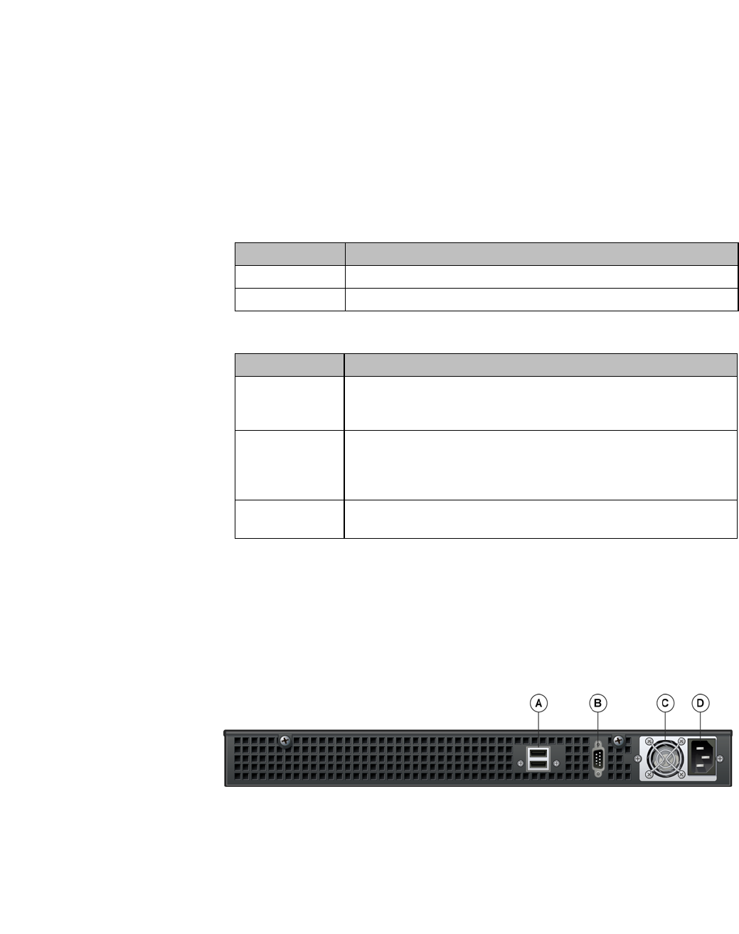
hwc_appendixa.fm
HiPath Wireless Controller’s physical description
HiPath Wireless Controller CRBT8210/8110
9034530-02, March 2010
HiPath Wireless Controller, Access Points and Convergence Software V7.11, User Guide 495
Figure 37 HiPath Wireless Controller CRBT8210/8110 front panel
A.6.2 Back panel
Figure 38 depicts the back panel features of the HiPath Wireless Controller
CRBT8110.
Figure 38 HiPath Wireless Controller CRBT8110 back panel
A. Hard drive
activity LED
D. Status/Power
LED
G. Power button
B. NIC 2
activity LED
E. Reset button H. NIC2 connector (10/100/1000 Mbit)
CRBT8110
NIC2 RJ-45 connector (10/100/1000 Base-
T) CRBT8210
C. NIC 1
activity LED
F. Console port
connector
I. NIC1 connector (10/100/1000 Mbit)
NIC1 RJ-45 connector (10/100/1000 Base-
T) CRBT8210
Button Function
Power Toggles the system power on/off.
Reset Performs a soft system reboot.
Table 43 Control button functions
LED Function
NIC1 activity
NIC2 activity
•A continuous amber light indicates a link between the system and
the network to which it is connected.
•A blinking amber light indicates network activity.
Status/Power •A continuous blue light indicates that the system has power
applied to it.
•No light indicates that the system does not have power applied to
it.
Hard drive
disk status
•A continuous blue light indicates a hard drive disk fault.
•A blinking blue light indicates hard drive activity.
Table 44 LED indicator status
A. USB connectors C. Power supply
B. Video connector D. Power connector

HiPath Wireless Controller’s physical description
hwc_appendixa.fm
HiPath Wireless Controller CRBT8210/8110
9034530-02, March 2010
496 HiPath Wireless Controller, Access Points and Convergence Software V7.11, User Guide
Note: The HiPath Wireless Controller CRBT8110 is equipped with two USB
connectors on the back panel. However, the controller is capable of supporting
only one USB device at a time, regardless of what USB connector the device is
connected to. If you connect a second USB device while the first is already
connected, the system will return an error.
Figure 39 depicts the back panel features of the HiPath Wireless Controller
CRBT8210.
Figure 39 HiPath Wireless Controller CRBT8210 back panel
A. Power supply B. Power connector

hwc_appendixb.fm
9034530-02, March 2010
HiPath Wireless Controller, Access Points and Convergence Software V7.11, User Guide 497
Regulatory information
B Regulatory information
Warning: Warnings identify essential information. Ignoring a warning can lead to
problems with the application.
This appendix provides regulatory information for the HiPath Wireless Controller
C20N/C20/C2400/C4110/C5110 and the HiPath Wireless AP models:
•AP 2610/2620 (AP26XX series)
•AP 3610/3620 (AP36XX series)
Note: Throughout this appendix, the term ‘Wireless AP’ refers to both AP models
(AP26XX series and AP36XX series). Specific AP models are only identified in
this appendix where it is necessary to do so.
Note: For technical specifications and certification information for the HiPath
Wireless Outdoor AP, models AP 2650/2660, see the HiPath Wireless Outdoor
AP Installation Guide.
Configuration of the Wireless AP frequencies and power output are controlled by
the regional software license and proper selection of the country during initial
installation and set-up. Customers are only allowed to select the proper country
from their licensed regulatory domain related to that customer’s geographic
location, thus allowing the proper set-up of access points in accordance with local
laws and regulations. The Wireless AP must not be operated until properly
configured with the correct country setting or it may be in violation of the local laws
and regulations.
Warning: Changes or modifications made to the HiPath Wireless Controller or
the Wireless APs which are not expressly approved by Siemens could void the
user's authority to operate the equipment.
Only authorized Siemens service personnel are permitted to service the system.
Procedures that should be performed only by Siemens personnel are clearly
identified in this guide.
Note: The HiPath Wireless Controllers and the Wireless APs are in compliance
with the European Directive 2002/95/EC on the restriction of the use of certain
hazardous substances (RoHS) in electrical and electronic equipment.

Regulatory information
hwc_appendixb.fm
HiPath Wireless Controller C20N/C20/C2400/C4110/C5110
9034530-02, March 2010
498 HiPath Wireless Controller, Access Points and Convergence Software V7.11, User Guide
B.1 HiPath Wireless Controller C20N/C20/C2400/C4110/C5110
Conformance standards and directives
Safety
•UL 60950-1 (U.S)
•CSA C22.2 No.60950-01-03 (Canada)
•2006/95/EC Low Voltage Directive (LVD)
•EN 60950-1 (Europe)
•IEC 60950-1 with applicable National Differences
•AS/NZS 60950.1 (Australia/New Zealand)
EMC (Emissions / Immunity)
•FCC Part 15, Subpart B, Class A (North America)
•ICES-003, Class A (Canadian Emissions)
•2004/108/EC EMC Directive
•EN 55022: Class A (European Emissions)
•ENEN 55024: includes EN 61000-4-2,3,4,5,6,11 (European Immunity)
•EN 61000-3-2: (Harmonics)
•EN 61000-3-3: (Flicker)
•IEC/CISPR 22: Class A (International Emissions)
•IEC/CISPR 24: includes IEC/EN 61000-4-2,3,4,5,6,11 (International
Immunity)
•Australia/New Zealand AS/NZS 3548 via EU standards (ACMA)
RoHS
•European Directive 2002/95/EC

hwc_appendixb.fm
Regulatory information
HiPath Wireless Controller C20N/C20/C2400/C4110/C5110
9034530-02, March 2010
HiPath Wireless Controller, Access Points and Convergence Software V7.11, User Guide 499
B.1.1 Rack mounting your system
Refer to the following guidelines when setting up your HiPath Wireless
Controllers and Wireless APs.
Elevated operating ambient
If installed in a closed or multi-unit rack assembly, the operating ambient
temperature of the rack environment may be greater than room ambient.
Therefore, consideration should be given to installing the equipment in an
environment compatible with the maximum ambient temperature (Tma) specified
by the manufacturer.
Reduced air flow
Installation of the equipment in a rack should be such that the amount of air flow
required for safe operation of the equipment is not compromised.
Mechanical loading
Mounting of the equipment in the rack should be such that a hazardous condition
is not achieved due to uneven mechanical loading.
Circuit overloading
Consideration should be given to the connection of the equipment to the supply
circuit and the effect that overloading of the circuits might have on over current
protection and supply wiring. Appropriate consideration of equipment nameplate
ratings should be used when addressing this concern.
Reliable earthing
Reliable earthing of rack-mounted equipment should be maintained. Particular
attention should be given to supply connections other than direct connections to
the branch circuit (e.g. use of power strips).

Regulatory information
hwc_appendixb.fm
Wireless APs 26XX and 36XX
9034530-02, March 2010
500 HiPath Wireless Controller, Access Points and Convergence Software V7.11, User Guide
B.2 Wireless APs 26XX and 36XX
This device is suitable for use in environmental air space in accordance with
Section 300.22.C of the National Electrical Code, and Sections 2-128, 12-010(3)
and 12-100 of the Canadian Electrical Code, Part 1, C22.1.
B.2.1 Wi-Fi certification
The AP26XX is Wi-Fi certified for operation in accordance with
IEEE 802.11a/b/g. The AP2610/20 Wireless APs with internal and external
antennas are designed and intended to be used indoors.
The AP36XX is Wi-Fi certified for operation in accordance with
IEEE 802.11a/b/g/n. The AP36XX Wireless APs with internal and external
antennas are designed and intended to be used indoors.
Note: Operation in the European Community and rest of the world may be
dependant on securing local licenses, certifications, and regulatory approvals.
B.2.2 AP2620 external antenna AP
Approved external antennas
The AP2620 external antenna APs can also be used with optional certified
external antennas:
•The external antennas on the AP2620 must be identical.
•Any unused antenna ports must be terminated when an external antenna is
used with the AP2620.
Antenna diversity
There are some limitations for using different antennas and Tx/Rx diversity:
Wireless AP model Wi-Fi certification ID
AP2605 WFA7482
AP2610 WFA7432
AP2620 WFA7387
AP2650 WFA7386
AP2660 WFA7431
AP3610 WFA6025
AP3620 WFA5917
Table 45 Wireless AP Wi-Fi certification ID

hwc_appendixb.fm
Regulatory information
Wireless APs 26XX and 36XX
9034530-02, March 2010
HiPath Wireless Controller, Access Points and Convergence Software V7.11, User Guide 501
•If Alternate antenna diversity is used for Tx or Rx, then the same antenna
model must be used as left and right antennas. In addition, if cables are used
to connect external antennas, the cables must be of the same length and
similar attenuation. If these rules are not respected, antenna diversity will not
function properly and there will be degradation in the link budget in both
directions.
•You can choose to install only one antenna provided that both Tx and Rx
diversity are configured to use that antenna and only that antenna. You can
choose to install one antenna for 11b/g band and one antenna for 11a band,
provided that the antenna diversity is configured appropriately on both radios.
Sensor support
Changing the antenna on sensors is not supported (at this stage) for the following
reasons:
•The sensor factors the antenna gain and pattern in its calculations and
therefore it needs to know the antenna type and gain.
•The sensor operating in mitigation mode becomes a transmitter and must
obey the same CTLs as the normal AP software.
•Neither the sensor nor the HiPath Wireless Manager HiGuard support
configuring the antenna.
B.2.3 AP3620 external antenna AP
Approved external antennas
The AP3620 external antenna APs can also be used with optional certified
external antennas:
•Any unused antenna ports must be terminated when an external antenna is
used with the AP3620.

Regulatory information
hwc_appendixb.fm
Wireless APs 26XX and 36XX
9034530-02, March 2010
502 HiPath Wireless Controller, Access Points and Convergence Software V7.11, User Guide
B.2.4 United States
B.2.4.1 FCC Declaration of Conformity Statement
This device complies with Part 15 of the FCC Rules. Operation is subject to the
following two conditions:
•This device may not cause harmful interference.
•This device must accept any interference received, including interference that
may cause undesired operation.
This equipment has been tested and found to comply with the limits for a Class B
digital device, pursuant to Part 15 of the FCC Rules. These limits are designed to
provide reasonable protection against harmful interference when the equipment
is operated in a residential and business environment. This equipment generates,
uses, and radiates radio frequency energy, and if not installed and used in
accordance with instructions, may cause harmful interference. However, there is
no guarantee that interference will not occur. If this equipment does cause
harmful interference, which can be determined by turning the equipment off and
on, the user is encouraged to try to correct the interference by one or more of the
following measures:
•Reorient or relocate the receiving antenna.
•Increase the separation between the equipment or devices.
•Connect the equipment to an outlet other than the receiver's.
•Consult a dealer or an experienced radio/TV technician for suggestions.
B.2.4.2 USA conformance standards
This equipment meets the following conformance standards:
Safety
•UL 60950-1
•UL 2043 Plenum Rated as part of UL 60950-1. Suitable for use in
environmental air space in accordance with Section 300.22.C of the National
Electrical Code.
EMC
•FCC CFR 47 Part 15, Class B
Radio transceiver
•CFR 47 Part 15.247, Subpart C

hwc_appendixb.fm
Regulatory information
Wireless APs 26XX and 36XX
9034530-02, March 2010
HiPath Wireless Controller, Access Points and Convergence Software V7.11, User Guide 503
•CFR 47 Part 15.407, Subpart E
Other
•IEEE 802.11a (5 GHz)
•IEEE 802.11b/g (2.4 GHz)
•IEEE 802.11n (AP36XX)
•IEEE 802.3af (PoE)
Warning: The Wireless APs must be installed and used in strict accordance with
the manufacturer's instructions as described in this guide and related
documentation for the device to which the Wireless AP is connected. Any other
installation or use of the product violates FCC Part 15 regulations.
Operation of the Wireless AP is restricted for indoor use only, specifically in the
UNII 5.15 - 5.25 GHz band in accordance with 47 CFR 15.407(e).
This Part 15 radio device operates on a non-interference basis with other devices
operating at the same frequency when using antennas provided or other Siemens
certified antennas. Any changes or modification to the product not expressly
approved by Siemens could void the user's authority to operate this device.
For the product available in the USA market, only channels 1 to 11 can be
operated. Selection of other channels in the 2.4 GHz band is not possible.
B.2.4.3 FCC RF Radiation Exposure Statement
The Wireless AP complies with FCC RF radiated exposure limits set forth for an
uncontrolled environment. End users must follow the specific operating
instructions for satisfying RF exposure compliance. This device has been tested
and has demonstrated compliance when simultaneously operated in the 2.4 GHz
and 5 GHz frequency ranges. This device must not be co-located or operated in
conjunction with any other antenna or transmitter.
Caution: The radiated output power of the Wireless AP is below the FCC radio
frequency exposure limits as specified in "Guidelines for Human Exposure to
Radio Frequency Electromagnetic Fields" (OET Bullet 65, Supplement C). This
equipment should be installed and operated with a minimum distance of 25 cm
between the radiator and your body or other co-located operating antennas.

Regulatory information
hwc_appendixb.fm
Wireless APs 26XX and 36XX
9034530-02, March 2010
504 HiPath Wireless Controller, Access Points and Convergence Software V7.11, User Guide
B.2.4.4 External antennas
The AP2620/AP3620 external antenna APs can also be used with certified
external antennas. However, in order to comply with the local laws and
regulations, an approval may be required by the local regulatory authorities.
For a list of approved external antennas, see Section B.2.8, “AP2620/AP3620
approved external antennas”.
RF safety distance
The antennas used for this transmitter must be installed to provide a separation
distance of at least 25 cm from all persons and must not be co-located or
operating in conjunction with another antenna or transmitter.

hwc_appendixb.fm
Regulatory information
Wireless APs 26XX and 36XX
9034530-02, March 2010
HiPath Wireless Controller, Access Points and Convergence Software V7.11, User Guide 505
B.2.5 Canada
B.2.5.1 Industry Canada Compliance Statement
This digital apparatus does not exceed the Class B limits for radio noise
emissions from digital apparatus as set out in the interference-causing equipment
standard entitled "Digital Apparatus," ICES-003 of Industry Canada.
Cet appareil numerique respecte les limites de bruits radioelectriques applicables
aux appareils numeriques de Classe B prescrites dans la norme sur le materiel
brouilleur: "Appareils Numeriques," NMB-003 edictee par le Industrie Canada.
This device complies with Part 15 of the FCC Rules and Canadian Standard
RSS-210. Operation is subject to the following conditions:
•This device may not cause harmful interference.
•This device must accept any interference received, including interference that
may cause undesired operation.
•This Class B digital apparatus complies with Canadian ICES-003.
•Operation in the 5150-5250 MHz band is only for indoor usage to reduce
potential for harmful interference to co-channel mobile satellite systems.
•Please note that high power radars are allocated as primary users (meaning
they have priority) and can cause interference in the 5250-5350 MHz and
5470-5725 MHz bands of LE-LAN devices.
•For the product available in the Canadian market, only channels 1 to 11 can
be operated. Selection of other channels in the 2.4 GHz band is not possible.
B.2.5.2 Canada conformance standards
This equipment meets the following conformance standards:
Safety
•C22.2 No.60950-1-03
•UL 2043 Plenum Rated as part of UL 60950-1. Suitable for use in
environmental air space in accordance with Sections 2-128, 12-010(3) and
12-100 of the Canadian Electrical Code, Part 1, C22.1
EMC
•ICES-003, Class B
Radio transceiver
•RSS-210 (2.4 GHz and 5GHz)

Regulatory information
hwc_appendixb.fm
Wireless APs 26XX and 36XX
9034530-02, March 2010
506 HiPath Wireless Controller, Access Points and Convergence Software V7.11, User Guide
Other
•IEEE 802.11a (5 GHz)
•IEEE 802.11b/g (2.4 GHz)
•IEEE 802.11n (AP36XX)
•IEEE 802.3af (PoE)
B.2.5.3 External antennas
The AP2620/AP3620 external antenna APs can also be used with certified
external antennas. However, in order to comply with the local laws and
regulations, an approval may be required by the local regulatory authorities.
For a list of approved external antennas, see Section B.2.8, “AP2620/AP3620
approved external antennas”.
RF safety distance
The antennas used for this transmitter must be installed to provide a separation
distance of at least 25 cm from all persons and must not be co-located or
operating in conjunction with another antenna or transmitter.

hwc_appendixb.fm
Regulatory information
Wireless APs 26XX and 36XX
9034530-02, March 2010
HiPath Wireless Controller, Access Points and Convergence Software V7.11, User Guide 507
B.2.6 European community
The Wireless APs are designed for use in the European Union and other
countries with similar regulatory restrictions where the end user or installer is
allowed to configure the Wireless AP for operation by entry of a country code
relative to a specific country. Upon connection to the controller, the software will
prompt the user to select a country code. After the country code is selected, the
controller will set up the Wireless AP with the proper frequencies and power
outputs for that country code.
Although outdoor use may be allowed and may be restricted to certain
frequencies and/or may require a license for operation, the Wireless AP is
intended for indoor use and must be installed in a proper indoor location. Use the
installation utility provided with the controller software to ensure proper set-up in
accordance with all European spectrum usage rules. Contact local Authority for
procedure to follow and regulatory information. For more details on legal
combinations of frequencies, power levels and antennas, contact Siemens.
Declaration of Conformity with R&TTE Directive of the European Union 1999/5/
EC
The following symbol indicates compliance with the Essential Requirements of
the R&TTE Directive of the European Union (1999/5/EC).

Regulatory information
hwc_appendixb.fm
Wireless APs 26XX and 36XX
9034530-02, March 2010
508 HiPath Wireless Controller, Access Points and Convergence Software V7.11, User Guide
B.2.6.1 Declaration of Conformity in Languages of the
European Community
English Hereby, Siemens, declares that this Radio LAN device is in compliance
with the essential requirements and other relevant provisions of Directive
1999/5/EC.
Finnish Valmistaja Siemens vakuuttaa täten että Radio LAN device tyyppinen laite
on direktiivin 1999/5/EY oleellisten vaatimusten ja sitä koskevien
direktiivin muiden ehtojen mukainen.
Dutch Hierbij verklaart Siemens dat het toestel Radio LAN device in
overeenstemming is met de essentiële eisen en de andere relevante
bepalingen van richtlijn 1999/5/EG.
Bij deze verklaart Siemens dat deze Radio LAN device voldoet aan de
essentiële eisen en aan de overige relevante bepalingen van Richtlijn
1999/5/EC.
French Par la présente Siemens déclare que l'appareil Radio LAN device est
conforme aux exigences essentielles et aux autres dispositions
pertinentes de la directive 1999/5/CE.
Par la présente, Siemens déclare que ce Radio LAN device est conforme
aux exigences essentielles et aux autres dispositions de la directive 1999/
5/CE qui lui sont applicables.
Swedish Härmed intygar Siemens att denna Radio LAN device står I
överensstämmelse med de väsentliga egenskapskrav och övriga
relevanta bestämmelser som framgår av direktiv 1999/5/EG.
Danish Undertegnede Siemens erklærer herved, at følgende udstyr Radio LAN
device overholder de væsentlige krav og øvrige relevante krav i direktiv
1999/5/EF.
German Hiermit erklärt Siemens die Übereinstimmung des "WLAN Wireless
Controller bzw. Access Points" mit den grundlegenden Anforderungen
und den anderen relevanten Festlegungen der Richtlinie 1999/5/EG.
Greek ΜΕ ΤΗΝ ΠΑΡΟΥΣΑ Siemens ∆ΗΛΩΝΕΙ ΟΤΙ Radio LAN device
ΣΥΜΜΟΡΦΩΝΕΤΑΙ ΠΡΟΣ ΤΙΣ ΟΥΣΙΩ∆ΕΙΣ ΑΠΑΙΤΗΣΕΙΣ ΚΑΙ ΤΙΣ
ΛΟΙΠΕΣ ΣΧΕΤΙΚΕΣ ∆ΙΑΤΑΞΕΙΣ ΤΗΣ Ο∆ΗΓΙΑΣ 1999/5/ΕΚ.
Icelandic Siemens lysir her med yfir að thessi bunadur, Radio LAN device, uppfyllir
allar grunnkrofur, sem gerdar eru i R&TTE tilskipun ESB nr 1999/5/EC.
Italian Con la presente Siemens dichiara che questo Radio LAN device è
conforme ai requisiti essenziali ed alle altre disposizioni pertinenti stabilite
dalla direttiva 1999/5/CE.
Spanish Por medio de la presente Siemens declara que el Radio LAN device
cumple con los requisitos esenciales y cualesquiera otras disposiciones
aplicables o exigibles de la Directiva 1999/5/CE.
Portuguese Siemens declara que este Radio LAN device está conforme com os
requisitos essenciais e outras disposições da Directiva 1999/5/CE.
Malti Hawnhekk, Siemens, jiddikjara li dan Radio LAN device jikkonforma mal-
htigijiet essenzjali u ma provvedimenti ohrajn relevanti li hemm fid-
Dirrettiva 1999/5/EC.

hwc_appendixb.fm
Regulatory information
Wireless APs 26XX and 36XX
9034530-02, March 2010
HiPath Wireless Controller, Access Points and Convergence Software V7.11, User Guide 509
New Member States requirements of Declaration of Conformity
Estonian Käesolevaga kinnitab Siemens seadme Radio LAN device vastavust
direktiivi 1999/5/EÜ põhinõuetele ja nimetatud direktiivist tulenevatele
teistele asjakohastele sätetele.
Hungary Alulírott, Siemens nyilatkozom, hogy a Radio LAN device megfelel a
vonatkozó alapvetõ követelményeknek és az 1999/5/EC irányelv egyéb
elõírásainak.
Slovak Siemens týmto vyhlasuje, že Radio LAN device spĺňa základné
požiadavky a všetky príslušné ustanovenia Smernice 1999/5/ES.
Czech Siemens tímto prohlašuje, že tento Radio LAN device je ve shodě se
základními požadavky a dalšími příslušnými ustanoveními směrnice
1999/5/ES."
Slovenian Šiuo Siemens deklaruoja, kad šis Radio LAN device atitinka esminius
reikalavimus ir kitas 1999/5/EB Direktyvos nuostatas.
Latvian Ar šo Siemens deklarē, ka Radio LAN device atbilst Direktīvas 1999/5/EK
būtiskajām prasībām un citiem ar to saistītajiem noteikumiem
Lithuanian Siemens deklaruoja, kad Radio LAN device atitinka 1999/5/EC
Direktyvos esminius reikalavimus ir kitas nuostatas".
Polish Niniejszym, Siemens, deklaruję, że Radio LAN device spełnia
wymagania zasadnicze oraz stosowne postanowienia zawarte
Dyrektywie 1999/5/EC.

Regulatory information
hwc_appendixb.fm
Wireless APs 26XX and 36XX
9034530-02, March 2010
510 HiPath Wireless Controller, Access Points and Convergence Software V7.11, User Guide
B.2.6.2 European conformance standards
This equipment meets the following conformance standards:
Safety
•2006/95/EC Low Voltage Directive (LVD)
•IEC/EN 60950-1 + National Deviations
EMC (Emissions / Immunity)
•2004/108/EC EMC Directive
•EN 55011/CISPR 11, Class B, Group 1 ISM
•EN 55022/CISPR 22, Class B
•EN 55024/CISPR 24, includes IEC/EN 61000-4-2,3,4,5,6,11
•EN 61000-3-2 and -3-3 (Harmonics and Flicker)
•EN 60601-1-2 (EMC immunity for medical equipment)
•EN 50385 (EMF)
•ETSI/EN 301 489-1 & -17
Radio transceiver
•R&TTE Directive 1999/5/EC
•ETSI/EN 300 328 (2.4 GHz)
•ETSI/EN 301 893 (5 GHz)
Other
•IEEE 802.11a (5 GHz)
•IEEE 802.11b/g (2.4 GHz)
•IEEE 802.11n (AP36XX)
•IEEE 802.3af (PoE)
RoHS
•European Directive 2002/95/EC

hwc_appendixb.fm
Regulatory information
Wireless APs 26XX and 36XX
9034530-02, March 2010
HiPath Wireless Controller, Access Points and Convergence Software V7.11, User Guide 511
B.2.6.3 External antennas
The AP2620/AP3620 external antenna APs can also be used with certified
external antennas. However, in order to comply with the local laws and
regulations, an approval may be required by the local regulatory authorities.
For a list of approved external antennas, see Section B.2.8, “AP2620/AP3620
approved external antennas”.
RF safety distance
The antennas used for this transmitter must be installed to provide a separation
distance of at least 25 cm from all persons and must not be co-located or
operating in conjunction with another antenna or transmitter.
B.2.6.4 Conditions of use in the European community
The Wireless APs with internal and external antennas are designed and intended
to be used indoors. Some EU countries allow outdoor operation with limitations
and restrictions, which are described in this section. It is the responsibility of the
end user to ensure operation in accordance with these rules, frequencies, and
transmitter power output. The Wireless AP must not be operated until properly
configured for the customer’s geographic location.
Caution: The user or installer is responsible to ensure that the Wireless AP is
operated according to channel limitations, indoor / outdoor restrictions, license
requirements, and within power level limits for the current country of operation. A
configuration utility has been provided with the HiPath Wireless Controller to
allow the end user to check the configuration and make necessary configuration
changes to ensure proper operation in accordance with the spectrum usage rules
for compliance with the European R&TTE directive 1999/5/EC.
The Wireless APs with internal and external antennas are designed to be
operated only indoors within all countries of the European Community. Some
countries require limited channels of operation. These restrictions are described
in this section.
Caution: The Wireless AP is completely configured and managed by the HiPath
Wireless Controller connected to the network. Please follow the instructions in
this user guide to properly configure the Wireless AP.
• The Wireless APs require the end user or installer to ensure that they have a
valid license prior to operating the Wireless AP. The license contains the region
and the region exposes the country codes which allow for proper configuration in
conformance with European National spectrum usage laws

Regulatory information
hwc_appendixb.fm
Wireless APs 26XX and 36XX
9034530-02, March 2010
512 HiPath Wireless Controller, Access Points and Convergence Software V7.11, User Guide
• There is a default group of settings that each Wireless AP receives when it
connects to the controller. There is the ability to change these settings. The user
or installer is responsible to ensure that each Wireless AP is properly configured.
• The software within the controller will automatically limit the allowable channels
and output power determined by the selected country code. Selecting the
incorrect country of operation or identifying the proper antenna used, may result
in illegal operation and may cause harmful interference to other systems.
• This device employs a radar detection feature required for European
Community operation in the 5 GHz band. This feature is automatically enabled
when the country of operation is correctly configured for any European
Community country. The presence of nearby radar operation may result in
temporary interruption of operation of this device. The radar detection feature will
automatically restart operation on a channel free of radar.
• The 5 GHz Turbo Mode feature is not enabled for use on the Wireless APs.
• The 5150- 5350 MHz band, channels 36, 40, 44, 48, 52, 56, 60, or 64, are
restricted to indoor use only.
• The external antenna APs must only use antennas that are certified by Siemens.
• The 2.4 GHz band, channels 1 - 13, may be used for indoor or outdoor use but
there may be some channel restrictions.
• In Greece and Italy, the end user must apply for a license from the national
spectrum authority to operate outdoors.
• In France, outdoor operation is not permitted in the 2.4 GHz band.

hwc_appendixb.fm
Regulatory information
Wireless APs 26XX and 36XX
9034530-02, March 2010
HiPath Wireless Controller, Access Points and Convergence Software V7.11, User Guide 513
B.2.6.5 European spectrum usage rules
The AP configured with approved internal or external antennas can be used for
indoor and outdoor transmissions throughout the European community as
displayed in Table 46. Some restrictions apply in Belgium, France, Greece, and
Italy.
Country 5.15-5.25 (GHz)
Channels:
36,40,44,48
5.25-5.35 (GHz)
Channels:
52,56,60,64
5.47-5.725 (GHz)
Channels:
100,104,108,112,116,
132,136,140
2.4-2.4835 (GHz)
Channels: 1 to 13
(Except Where Noted)
Austria Indoor only Indoor only Indoor or outdoor Indoor or outdoor
Belgium Indoor only Indoor only Indoor or outdoor * Indoor or outdoor
Bulgaria Indoor only Indoor only Indoor or outdoor Indoor or outdoor
Denmark Indoor only Indoor only Indoor or outdoor Indoor or outdoor
Croatia Indoor only Indoor only Indoor or outdoor Indoor or outdoor
Cyprus Indoor only Indoor only Indoor or outdoor Indoor or outdoor
Czech Rep. Indoor only Indoor only Indoor or outdoor Indoor or outdoor
Estonia Indoor only Indoor only Indoor or outdoor Indoor or outdoor
Finland Indoor only Indoor only Indoor or outdoor Indoor or outdoor
France Indoor only Indoor only Indoor or outdoor Indoor only
Germany Indoor only Indoor only Indoor or outdoor Indoor or outdoor
Greece Indoor only Indoor only Indoor
(Outdoor w/License)
Indoor
(Outdoor w/license)
Hungary Indoor only Indoor only Indoor or outdoor Indoor or outdoor
Iceland Indoor only Indoor only Indoor or outdoor Indoor or outdoor
Ireland Indoor only Indoor only Indoor or outdoor Indoor or outdoor
Italy Indoor only Indoor only Indoor or outdoor Indoor
(Outdoor w/license)
Latvia Indoor only Indoor only Indoor or outdoor Indoor or outdoor
Liechtenstein Indoor only Indoor only Indoor or outdoor Indoor or outdoor
Lithuania Indoor only Indoor only Indoor or outdoor Indoor or outdoor
Luxembourg Indoor only Indoor only Indoor or outdoor Indoor or outdoor
Netherlands Indoor only Indoor only Indoor or outdoor Indoor or outdoor
Malta Indoor only Indoor only Indoor or outdoor Indoor or outdoor
Norway Indoor only Indoor only Indoor or outdoor Indoor or outdoor
Poland Indoor only Indoor only Indoor or outdoor Indoor or outdoor
Portugal Indoor only Indoor only Indoor or outdoor Indoor or outdoor
Romania Indoor only Indoor only Indoor or outdoor Indoor or outdoor
Slovak Rep. Indoor only Indoor only Indoor or outdoor Indoor or outdoor
Slovenia Indoor only Indoor only Indoor or outdoor Indoor or outdoor
Table 46 European spectrum usage rules

Regulatory information
hwc_appendixb.fm
Wireless APs 26XX and 36XX
9034530-02, March 2010
514 HiPath Wireless Controller, Access Points and Convergence Software V7.11, User Guide
Note: * Belgium requires notifying the spectrum agency if deploying > 300 meter
wireless links in outdoor public areas.
Spain Indoor only Indoor only Indoor or outdoor Indoor or outdoor
Sweden Indoor only Indoor only Indoor or outdoor Indoor or outdoor
Switzerland Indoor only Indoor only Indoor or outdoor Indoor or outdoor
Turkey Indoor only Indoor only Indoor or outdoor Indoor or outdoor
U.K Indoor only Indoor only Indoor or outdoor Indoor or outdoor
Country 5.15-5.25 (GHz)
Channels:
36,40,44,48
5.25-5.35 (GHz)
Channels:
52,56,60,64
5.47-5.725 (GHz)
Channels:
100,104,108,112,116,
132,136,140
2.4-2.4835 (GHz)
Channels: 1 to 13
(Except Where Noted)
Table 46 European spectrum usage rules

hwc_appendixb.fm
Regulatory information
Wireless APs 26XX and 36XX
9034530-02, March 2010
HiPath Wireless Controller, Access Points and Convergence Software V7.11, User Guide 515
B.2.7 Certifications of other countries
The Wireless APs have been certified for use in various other countries. When
the Wireless AP is connected to the Siemens HiPath Wireless Controller, the user
is prompted to select a country code. Once the correct country code is selected,
the controller automatically sets up the Wireless AP with the proper frequencies
and power outputs for that country code.
Note: It is the responsibility of the end user to select the proper country code for
the country the device will be operated within or run the risk violating local laws
and regulations.
Approved external antennas
The external antenna Wireless APs can also be used with certified external
antennas. However, in order to comply with the local laws and regulations, an
approval may be required by the local regulatory authorities.
For a list of approved external antennas, see Section B.2.8, “AP2620/AP3620
approved external antennas”.
Other country specific compliance standards, approvals and declarations
•IEC 60950-1 CB Scheme + National Deviations
•AS/NZS 60950.1 (Safety)
•AS/NZS 3548 (Emissions via EU standards – ACMA)
•AS/NZS 4288 (Radio via EU standards)
•EN 300 328 (2.4 GHz)
•EN 301 893 (5 GHz)
•EN 301 489-1 & -17 (RLAN)
•IEEE 802.11a (5 GHz)
•IEEE 802.11b/g (2.4 GHz)
•IEEE 802.11n (AP36XX)
•IEEE 802.3af (PoE)

Regulatory information
hwc_appendixb.fm
Wireless APs 26XX and 36XX
9034530-02, March 2010
516 HiPath Wireless Controller, Access Points and Convergence Software V7.11, User Guide
B.2.8 AP2620/AP3620 approved external antennas
The AP2620/AP3620 external antenna APs can be used with certified external
antennas. However, in order to comply with the local laws and regulations, an
approval may be required by the local regulatory authorities. The following
optional antennas have been tested and approved for use with the external
antenna models.
Model Application Shape Gain (dBi) Frequency
(MHz) Connector
Type
WS-ANT01 outdoor omni 4 2400-2500
5150-5900
RPSMA
WS-AO-DS05360 outdoor omni 5 2400-2500
5150-5350
N-female
WS-AIO-5S12060 indoor panel 12 2400-2500
4900-5990
N-female
WS-AI-2S03360 indoor omni 3.5 2400-2500 RPSMA
WS-AI-DS06360 indoor omni 5
6
2300-2700
4900-6000
RPSMA
WS-AIO-DS05120 indoor/outdoor panel 5 2400-2500 N-female
WS-AIO-2S07060 indoor/outdoor panel 7.5 2300-2600
4900-6000
N-female
WS-AIO-5S17017 indoor/outdoor panel 17 5470-5850 N-female
WS-AIO-2514090 indoor/outdoor panel 14 2400-2485 N-female
WS-AIO-5S15090 indoor/outdoor panel 15 4900-6000 N-female
WS-AIO-2S18018 indoor/outdoor panel 18 2300-2500 N-female
Table 47 List of FCC approved antennas — AP2620
Model Application Shape Gain (dBi) Frequency
(MHz) Connector
Type
WS-ANT02 indoor omni 4 2400-2500
5150-5900
RPSMA
WS-AO-DS05360 outdoor omni 5 2400-2500
5150-5350
N-female
WS-AO-D16060 outdoor 60 degree sector
directional, 2 inputs
16 5150-5875 N-female
WS-AO-5D23009 outdoor panel, 2 inputs 23 5150-5875 N-female
WS-AI-DT04360 indoor omni, 3 inputs 3
4
2400-2500
4900-5990
RPSMA, 3ea.
WS-AI-DT05120 indoor 120 degree sector
directional, 3 inputs
5 2300-2700
4900-6100
RPSMA
Table 48 List of FCC approved antennas — AP3620

hwc_appendixb.fm
Regulatory information
Wireless APs 26XX and 36XX
9034530-02, March 2010
HiPath Wireless Controller, Access Points and Convergence Software V7.11, User Guide 517
RF safety distance
The antennas used for this transmitter must be installed to provide a separation
distance of at least 25 cm from all persons and must not be co-located or
operating in conjunction with another antenna or transmitter.

Regulatory information
hwc_appendixb.fm
Wireless APs 26XX and 36XX
9034530-02, March 2010
518 HiPath Wireless Controller, Access Points and Convergence Software V7.11, User Guide

hwc_appendixc.fm
9034530-02, March 2010
HiPath Wireless Controller, Access Points and Convergence Software V7.11, User Guide 519
optiPoint WL2 Configuration
optiPoint WL2 wireless telephone configuration
C optiPoint WL2 Configuration
This appendix describes the recommended configuration for the optiPoint WL2
wireless telephone with the HiPath Wireless LAN Solution. In addition,
corresponding configurations should be made on the PBX, if applicable.
Update your optiPoint WL2 wireless telephone software to the latest available
firmware. The following information in this appendix refers to an optiPoint WL2
telephone running firmware version 50.002.43.00079.
Note: You can also use the VNS wizard to configure the HiPath Wireless
Controller for use with optiPoint wireless telephones. For more information, see
Section 6.4.2, “Creating a voice VNS using the VNS wizard”, on page 262.
C.1 optiPoint WL2 wireless telephone configuration
To configure audio settings:
1. Launch your Web browser, and in the browser address bar type the optiPoint
WL2’s IP address. The optiPoint WL2 professional Handset screen is
displayed.
2. In the optiPoint WL2 professional menu, click Admin. The Network: Profile
Selection screen is displayed.
3. In the left pane, click Audio Settings. The Audio Settings screen is
displayed.
4. Configure the following audio settings:
•In the Codec drop-down list, click G.711 preferred (normal quality).
The alternative G729 codec would only provide a small increase in
capacity at the expense of a significant increase in sensitivity to lost
packets and degradation of quality.
•In the RTP Packet Size drop-down list, click 20ms.
The 10ms setting would not improve voice quality, but it would
significantly decrease the per-AP voice capacity. The 30ms setting would
worsen the impact of lost packets while roaming.
•Clear the Silence Suppression checkbox. The Silence Suppression
option should be disabled.
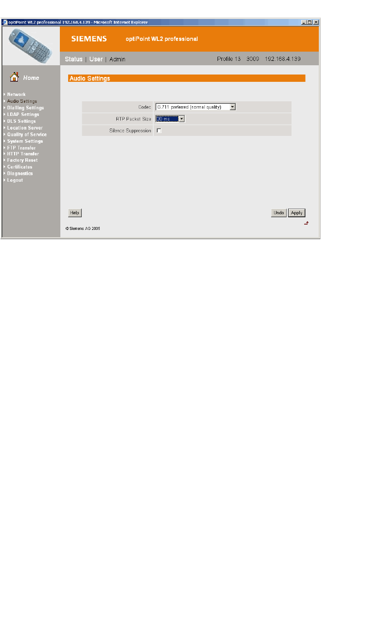
optiPoint WL2 Configuration
hwc_appendixc.fm
optiPoint WL2 wireless telephone configuration
9034530-02, March 2010
520 HiPath Wireless Controller, Access Points and Convergence Software V7.11, User Guide
To configure Quality of Service protocol settings:
1. In the left pane, click Quality of Service. The Quality of Service: Protocol
Settings screen is displayed.
2. Configure the following Quality of Service settings:
•In the DSCP Class for Voice drop-down list, click Expedited
Forwarding to ensure maximum voice priority.
•In the DSCP Class for Signalling drop-down list, click Assured
Forwarding 3.
Under normal conditions Assured Forwarding 3 ensures a more reliable
delivery for Signaling than for Voice (more retries) at the expense of a
potential higher delay.
•In the VLAN Settings section, select None.
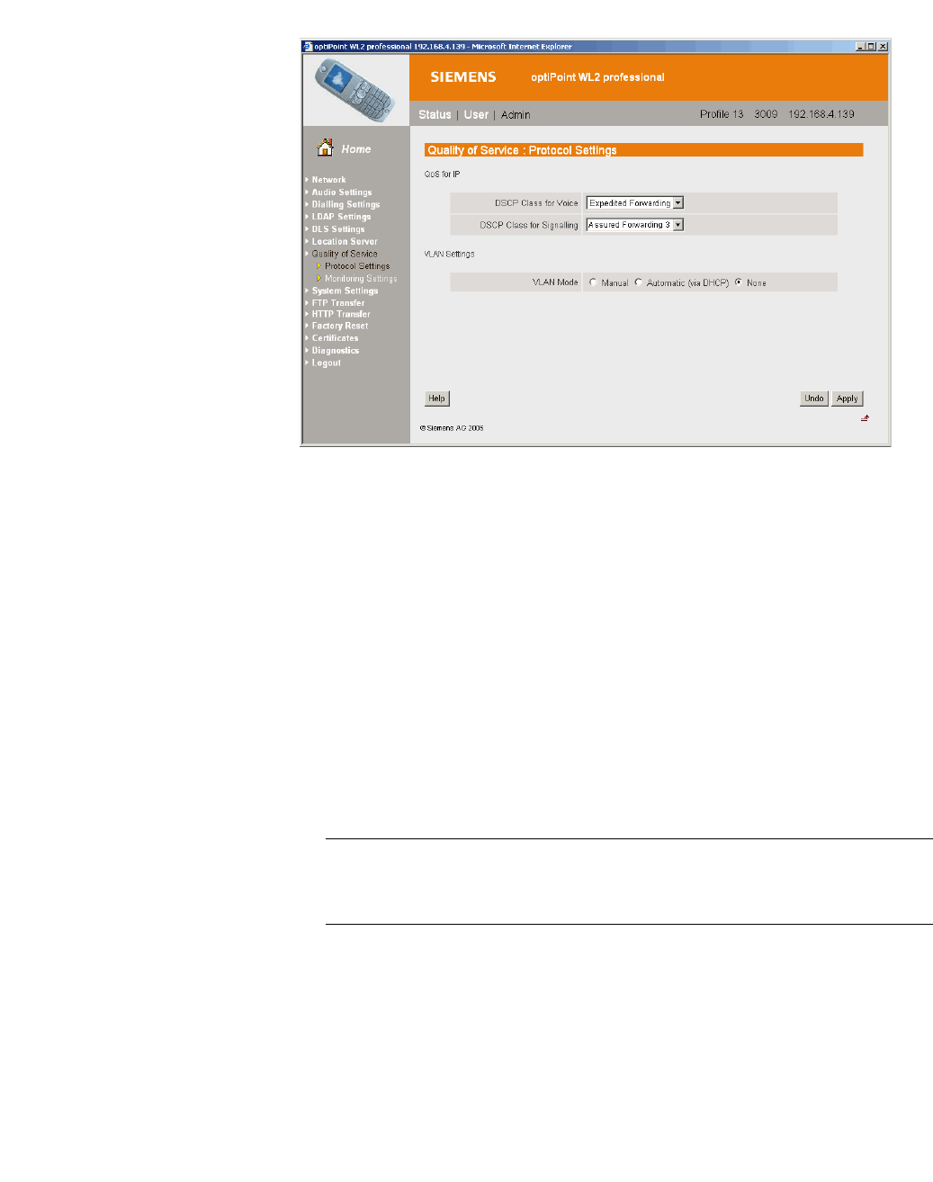
hwc_appendixc.fm
optiPoint WL2 Configuration
optiPoint WL2 wireless telephone configuration
9034530-02, March 2010
HiPath Wireless Controller, Access Points and Convergence Software V7.11, User Guide 521
To configure WLAN settings:
1. In the left pane, click Network. The Network: Profile Selection screen is
displayed.
2. In the List of Profiles, click Edit for the profile you want to configure. The
Network: Profile Name screen is displayed.
3. In the left pane, click WLAN. The Network: WLAN for profile screen is
displayed.
4. Configure the following WLAN settings:
•In the Output Power (in%) drop-down list, click 100.
Use the maximum 100% unless there is a reason to reduce it.
•In the Transmission Rate drop-down, click Auto.
Note: When the Transmission Rate is set to a value, it does not force the
phone to only use that particular PHY transmission rate. Instead, it forces the
phone to only use PHY rates that are smaller or equal to the set rate.
•In the Fragmentation Threshold box, ensure that the default value 2346
is used.
•In the RTS/CTS Threshold box, ensure that the default value 2347 is
used.
•In the Roaming Threshold box, type a roaming threshold between the
range of -75 dBm to -65 dBm, depending on the parameters of the
deployment.
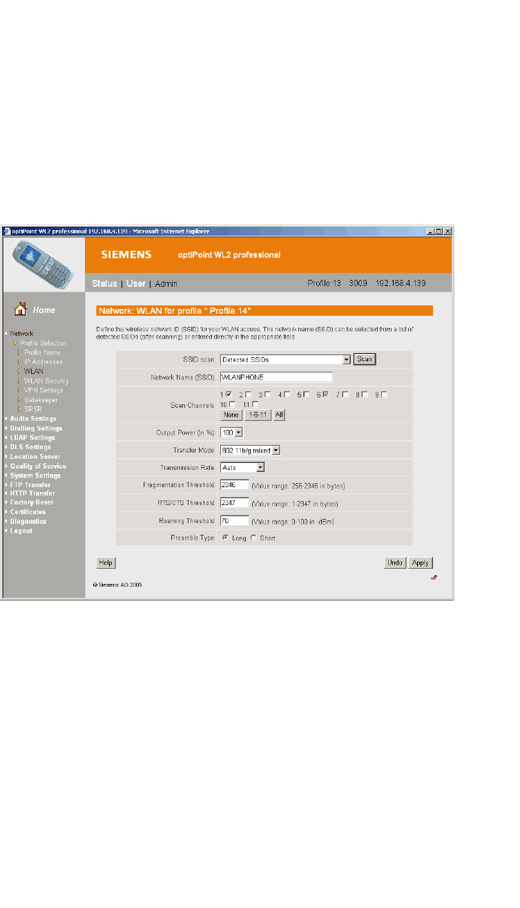
optiPoint WL2 Configuration
hwc_appendixc.fm
optiPoint WL2 wireless telephone configuration
9034530-02, March 2010
522 HiPath Wireless Controller, Access Points and Convergence Software V7.11, User Guide
A larger value, for example -65 dBm will cause the phone to scan for
alternate Wireless APs more often, which will result in more wireless
traffic and slightly decreased battery life. A smaller value, for example -75
dBm will cause the phone to roam too late, causing voice interruptions
during roaming.
•In the Preamble Type section, select Short. The short preamble
provides for higher voice capacity.
If legacy pre-11b devices are present in the coverage area or you are
unsure if legacy pre-11b devices are present in the coverage area, select
Long.
To configure WLAN security settings:
1. In the left pane, click Network. The Network: Profile Selection screen is
displayed.
2. In the left pane, click WLAN Security. The Network: WLAN Security for
profile screen is displayed.
3. Configure the following WLAN security settings:
•Click WPA-PSK.
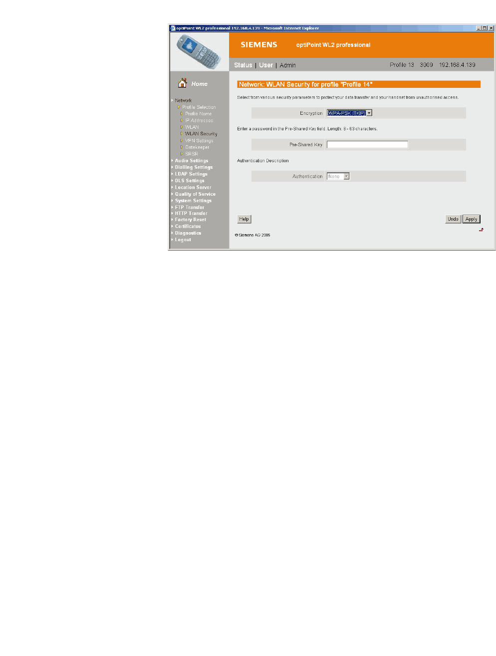
hwc_appendixc.fm
optiPoint WL2 Configuration
HiPath Wireless Controller configuration
9034530-02, March 2010
HiPath Wireless Controller, Access Points and Convergence Software V7.11, User Guide 523
C.2 HiPath Wireless Controller configuration
The easiest way to configure a voice VNS is to use the VNS Creation Wizard.
Refer to Section 6.4.2, “Creating a voice VNS using the VNS wizard”, on page
262.
The following settings must be configured on the HiPath Wireless Controller.
•A dedicated VNS must be used for WL2 phones. No other non-voice clients
should be allowed in this VNS.
•The VNS must be a non-RADIUS VNS.
To configure a WL2 Voice Topoiogy:
1. In the Layer 3 area, from the DHCP drop-down list, select Local Server, then
click Configure.
2. Select the Enable DLS DHCP Option checkbox.
3. In the DLS Address box, type the IP address or the DNS name of the DLS.
In the accompanying box, type the DLS port number. The default is 18443.
For more information about configuring a Topology, see Section 6.8, “Configuring
a Topology”, on page 296.
To configure a WL2 WLAN Service:
1. Click the Privacy tab.
2. Configure the following privacy settings:

optiPoint WL2 Configuration
hwc_appendixc.fm
HiPath Wireless Controller configuration
9034530-02, March 2010
524 HiPath Wireless Controller, Access Points and Convergence Software V7.11, User Guide
•The privacy settings on the HiPath Wireless Controller must match those
on the optiPoint WL2 phone.
•If the optiPoint WL2 phone is configured to use WPA-PSK, select the
WPA-PSK option for the VNS.
3. Click the QoS tab.
4. Configure the following QoS policy settings:
•For good voice quality and battery life, select WMM.
•If the VNS is shared with legacy devices that require priority but do not
support WMM, select Legacy.
•If applicable, select 802.11e or Enable U-APSD. (The next release of the
optiPoint WL2 may require .11e support).
Note: The Turbo Voice and Use Global Admission Control for Voice (VO)
options should be cleared. These options should not be used in the same
VNS as the optiPoint WL2. These features are not currently supported on the
optiPoint WL2.
•The Priority Override option (configured on the Advanced dialog) should
normally be cleared. If the phone and PBX are configured properly, the
default DSCP classification should work well. If you are unsure, sniff the
packets over the air and check that the voice packets are sent with priority
6 or 7 in both UL and DL directions.
For more information about configuring a WLAN Service, see Section 6.9,
“Configuring WLAN Services”, on page 308.
To configure Wireless AP radio properties:
1. From the main menu, click Wireless AP Configuration. The HiPath
Wireless AP screen is displayed.
2. Click the applicable radio tab, In the Radio Mode drop-down list, click g.
Note: Enable 11b only if 11b devices are used on the same VNS as the
optiPoint WL2 phone.
3. Click the Advanced button.
4. Configure the following radio settings:

hwc_appendixc.fm
optiPoint WL2 Configuration
HiPath Wireless Controller configuration
9034530-02, March 2010
HiPath Wireless Controller, Access Points and Convergence Software V7.11, User Guide 525
•In the DTIM Period box, type 5.
Note: A DTIM Period value of 1 may produce better results if significant
RF interference exists in your environment. Use a DTIM Period value of
5 unless you notice a significant improvement when using a value of 1.
•In the Beacon Period box, type 100 (ms).
•In the RTS/CTS Threshold box, ensure that the default value 2346 is
used.
•In the Frag. Threshold box, ensure that the default value 2346 is used.
•In the Rx Diveristy drop-down list, click Best.
•In the Tx Diversity drop-down list, click Alternate.
Note: If you experience variable or unstable signals, in the Tx Diversity
drop-down list, click Left.
•In the Min Basic Rate drop-down list, click 1Mbps if .11b is enabled.
Note: Use a Min Basic Rate of 6Mbps if you are using only optiPoint
WL2 phones on the VNS, as this will increase the number of concurrent
calls per AP. Use a Min Basic Rate of 2Mbps or 1Mbps if your site has
sparse RF coverage.
•In the Max Basic Rate drop-down list, click the default maximum possible
basic rate. For example, click 12 Mbps if you are using 6 Mbps as the
Min Basic Rate. Otherwise, click 24 Mbps.
•In the Max Operational Rate drop-down list, click the default maximum
rate. For example, 54 Mbps.
•In the Preamble drop-down list, click Short. The short preamble provides
for higher voice capacity.
If legacy pre-11b devices are present in the coverage area or you are
unsure if legacy pre-11b devices are present in the coverage area, click
Long.
•In the Total # of Tries for Background BK drop-down list, click adaptive
(multi-rate).
•In the Total # of Tries for Best Effort BE drop-down list, click adaptive
(multi-rate).
•In the Total # of Tries for Video VI drop-down list, click adaptive
(multi-rate).

optiPoint WL2 Configuration
hwc_appendixc.fm
HiPath Wireless Controller configuration
9034530-02, March 2010
526 HiPath Wireless Controller, Access Points and Convergence Software V7.11, User Guide
•In the Total # of Tries for Voice VO drop-down list, click adaptive
(multi-rate).
•In the Total # of Tries for Turbo Voice TVO drop-down list, click
adaptive (multi-rate).
Note: At a minimum, use adaptive (multi-rate) for Total # of Tries for Best
Effort BE and Total # of Tries for Voice VO since this will significantly
improve voice quality.
•In the Protection Mode drop-down list, click Auto.
•In the Protection Rate drop-down list, click 11 Mbps.
•In the Protection Type drop-down list, click CTS. The CTS protection
mode allows for higher voice capacity.
If legacy pre-11b devices are present in the coverage area or you are
unsure if legacy pre-11b devices are present in the coverage area, click
RTS CTS. RTS CTS mode provides more robust protection.
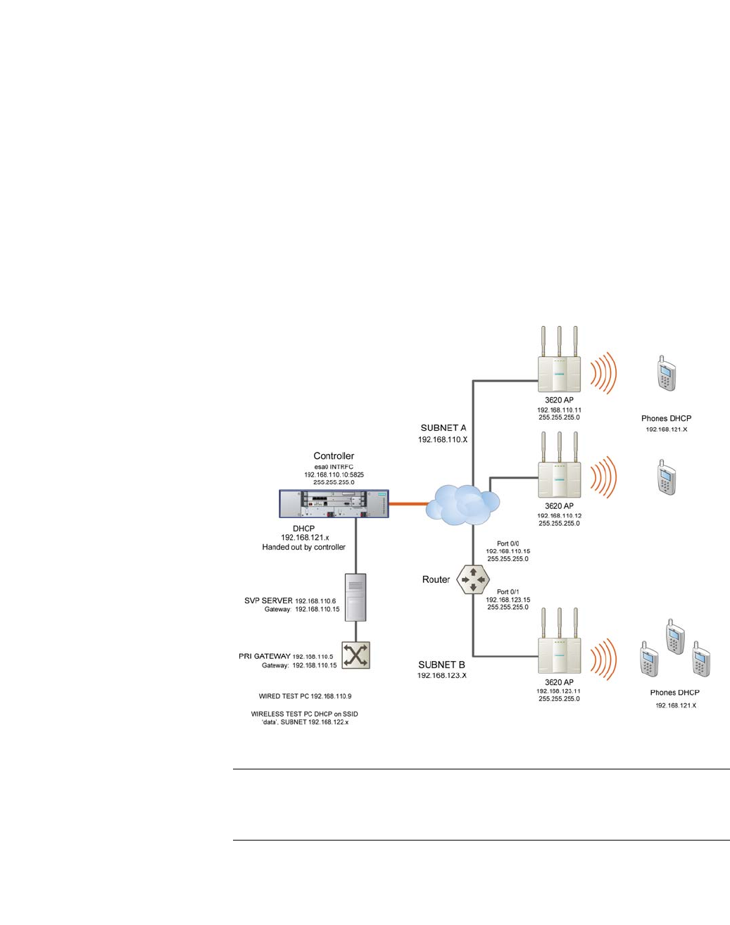
hwc_appendixd.fm
9034530-02, March 2010
HiPath Wireless Controller, Access Points and Convergence Software V7.11, User Guide 527
SpectraLink Wireless Telephones
Network Topology
D SpectraLink Wireless Telephones
The HiPath Wireless LAN Solution, consisting of the HiPath Wireless Controller,
Wireless APs, and the HiPath Wireless Convergence Software, seamlessly
integrates with SpectraLink Wireless Telephones to serve mobile voice and data
requirements. The standards-based architecture of HiPath Wireless LAN
provides an exceptional infrastructure for voice quality and handset-reliability to
the SpectraLink telephones.
D.1 Network Topology
The following image depicts a typical network topology for SpectraLink
telephones.
Figure 40 SpectraLink Network Topology
Note: The network topology depicted in Figure 40 is a dedicated network for
SpectraLink Telephones. Other topologies are supported and can be used as
required.

SpectraLink Wireless Telephones
hwc_appendixd.fm
Configuring HiPath Wireless Controller for SpectraLink telephones
9034530-02, March 2010
528 HiPath Wireless Controller, Access Points and Convergence Software V7.11, User Guide
Note: For a successful deployment, all network elements in the SpectraLink
network should be provisioned to prioritize voice data.
D.2 Configuring HiPath Wireless Controller for SpectraLink telephones
This section describes how to configure the HiPath Wireless Controller and
Wireless APs for use with SpectraLink Wireless telephones.
You have to configure the following features in the HiPath Wireless Controller to
set it up for SpectraLink telephones:
•Radio properties
•SSID
•Filters
•Multicast configuration
•Security
•Quality of Service (QoS)
The configuration process for SpectraLink telephones applies identically to
HiPath Wireless APs, HiPath Wireless Outdoor APs and HiPath Wireless 802.11n
APs, unless specified otherwise.
Note: You can also use the VNS wizard to configure the HiPath Wireless
Controller for use with SpectraLink Wireless telephones. For more information,
see Section 6.4.2, “Creating a voice VNS using the VNS wizard”, on page 262.
D.2.1 Setting up SSID
To set up the SSID:
1. From the main menu, click Virtual Network Configuration. The Virtual
Network Configuration screen is displayed.
2. In the left pane, expand the New pane and click Add VNS (subnet).
3. Type a name that will identify the new VNS in the VNS Name box.

hwc_appendixd.fm
SpectraLink Wireless Telephones
Configuring HiPath Wireless Controller for SpectraLink telephones
9034530-02, March 2010
HiPath Wireless Controller, Access Points and Convergence Software V7.11, User Guide 529
4. In the Default Policies area, select an existing Non-Authenticated and
Authenticated policy, or create a new one by clicking the New button. The
Policy configuration window is displayed.
5. From the Topology area, select an existing topology from the Assigned
Topology drop-down list. or create a new one by clicking the New button.
Note: It is recommended that you should choose Bridge Traffic Locally at
HWC Topology Mode for SpectraLink network deployment.
6. In the Layer 3 area, from the DHCP Option drop-down menu, you can select
either the Local DHCP Server or Use DHCP Relay, depending upon your
network topology. Click the Configure button.
7. In the Gateway box, type the network gateway address.
8. In the Mask box, type the appropriate values.
9. In the Address Range boxes (from and to), type the IP address range.
10. To save your changes, click Save.
D.2.2 Configuring filters
To configure the filters:
1. From the main menu, click Virtual Network Configuration. The Virtual
Network Configuration screen is displayed.
2. In the left pane, expand the Policies pane and select the policy to configure.
3. On the Policy Configuration screen, click the Filter Rules tab. The filtering
rule for the Default filter is displayed in the centre pane.
4. Click the Add button, then type the IP address of SVP server in IP/Subnet
and port boxes.
5. From the Protocol drop-down menu, select UDP.
6. Click OK. The new filtering rule for the SVP server is displayed in the centre
pane.
7. Click Up. The filtering rule for the SVP server moves up, before the filter rule
for Default filter.
8. Click Add again, then type the IP address of SpectraLink Gateway in IP/
Subnet and port boxes, and then repeat steps 5 to 7.

SpectraLink Wireless Telephones
hwc_appendixd.fm
Configuring HiPath Wireless Controller for SpectraLink telephones
9034530-02, March 2010
530 HiPath Wireless Controller, Access Points and Convergence Software V7.11, User Guide
9. Add the filtering rules for the IP addresses of all network elements as
explained in steps 5 to 7.
Note: You must ensure that all the filtering rules, including the ones for SVP/
Gateway and other network elements, are moved up, before the filtering rule
for the Default filter.
10. Select the Allow option of the Default filter.
11. To save your changes, click Save.
Note: You must complete the remaining configuration as explained in the
subsequent sections, and then check if the deployment is working properly. If
the deployment is working properly, you should deselect Allow option of the
Default filter in order to secure the network
The secure setup in context of the network topology illustrated in Figure 40
on page 527 will be as follows:
• Allow 192.168.121.* UDP
• Allow 192.168.110.* UDP
• Allow 192.168.123.* UDP
• Disallow *.*.*.* N/A T

hwc_appendixd.fm
SpectraLink Wireless Telephones
Configuring HiPath Wireless Controller for SpectraLink telephones
9034530-02, March 2010
HiPath Wireless Controller, Access Points and Convergence Software V7.11, User Guide 531
D.2.3 Setting up multicast configuration
Note: Before you set up multicast configuration, you must specify the physical
port for routing multicast traffic on the Wireless Controller configuration
screen.
To set up multicast configuration:
1. From the main menu, click Virtual Network Configuration. The Virtual
Network Configuration screen is displayed.
2. In the left pane, expand the Topologies pane and select the desired topology.
3. Select the Multicast Filters tab, then select the Enable Multicast Support
checkbox.
4. From the Defined groups drop-down list, select Spectralink SVP
(224.0.1.116) and then click Add.
5. Select the Wireless Replication checkbox.
6. To save your changes, click Save.

SpectraLink Wireless Telephones
hwc_appendixd.fm
Configuring HiPath Wireless Controller for SpectraLink telephones
9034530-02, March 2010
532 HiPath Wireless Controller, Access Points and Convergence Software V7.11, User Guide
D.2.4 Setting up Security
To set up the security:
1. From the main menu, click Virtual Network Configuration. The Virtual
Network Configuration screen is displayed.
2. In the left pane, expand the WLAN Services pane, then select the desired
WLAN Service.
3. Click the Privacy tab.
4. Select the WPA-PSK option.
5. Select the WPA v.2 option.
6. Under WPA v.2 section, select AES only from the Encryption drop-down
menu.
Note: The SpectraLink telephones must also be configured for WPA v.2
security.
7. Enter the appropriate pass phrase in the Pre-shared key field.
8. To save your changes, click Save.
D.2.5 Setting up Quality of Service (QoS)
To set up Quality of Service (QoS):
1. From the main menu, click Virtual Network Configuration. The Virtual
Network Configuration screen is displayed.
2. In the left pane, expand the WLAN Services pane, then select the desired
WLAN Service.
3. Click the QoS tab.
4. Under the Wireless QoS section, select the following:
•Legacy
•Turbo Voice
Note: If you are using HiPath Wireless APs and HiPath Wireless Outdoor
APs, you must ensure that Turbo Voice QoS is selected to achieve best
voice quality with the SpectraLink telephones.

hwc_appendixd.fm
SpectraLink Wireless Telephones
Configuring HiPath Wireless Controller for SpectraLink telephones
9034530-02, March 2010
HiPath Wireless Controller, Access Points and Convergence Software V7.11, User Guide 533
Turbo Voice QoS does not have any effect on HiPath Wireless 802.11n APs
as these APs provide best voice quality regardless of whether Turbo Voice
QoS is selected or not.
Note: To achieve “higher call capacity”, you must ensure that WMM QoS is
deselected.
Note: The HiPath Wireless 802.11n APs support only the WMM QoS. If you
are using 802.11n APs, and you want to achieve “higher call capacity”, you
must ensure that WMM QoS is deselected.
The Turbo Voice QoS does not have any effect on the 802.11n APs
regardless of whether it is selected or not.
5. Click the Advanced button.
6. Under the Priority Processing section, select Priority Override.
7. Retain the default value in Service Class drop-down menu.
8. Retain the default value in DSCP marking drop-down menu.
9. To save your changes, click Save.
D.2.6 Setting up Radio Properties
To set up the radio for Voice Wireless LAN in HiPath Wireless AP (Models
2610/2620):
1. From the main menu, click Wireless AP Configuration. The Wireless AP
Configuration screen is displayed.
2. From the list of Wireless APs, select the Wireless AP that is being used for
the Voice WLAN.
3. On the Wireless AP Configuration screen, select the tab for the radio that
is being used for Voice WLAN.
4. Click the Advanced button.
5. Under Base Settings, set the DTIM Period to 3.
6. Under Basic Radio Settings, set the following parameters:
• Tx Diversity: Set the Tx Diversity to either Left or Right.

SpectraLink Wireless Telephones
hwc_appendixd.fm
Configuring HiPath Wireless Controller for SpectraLink telephones
9034530-02, March 2010
534 HiPath Wireless Controller, Access Points and Convergence Software V7.11, User Guide
• Total # of retries for Voice VO: Set the Total # of retries for Voice VO
to adaptive (multi-rate).
Note: It is recommended that the Tx Diversity should be set to Left.
7. Retain the default values for all other parameters.
8. To save your changes, click Save.
To set up the radio for Voice Wireless LAN in HiPath Wireless 802.11n APs
(Models AP3610/3620):
1. From the main menu, click Wireless AP Configuration. The Wireless AP
Configuration screen is displayed.
2. From the list of Wireless APs, select the Wireless 802.11n AP that is being
used for the Voice WLAN.
3. On the Wireless AP Configuration screen, select the tab for the radio that
is being used for the Voice WLAN.
4. Click the Advanced button.
5. Under Base Settings, set the DTIM Period to 3.
6. Retain the default values for all other parameters.
7. To save your changes, click Save.
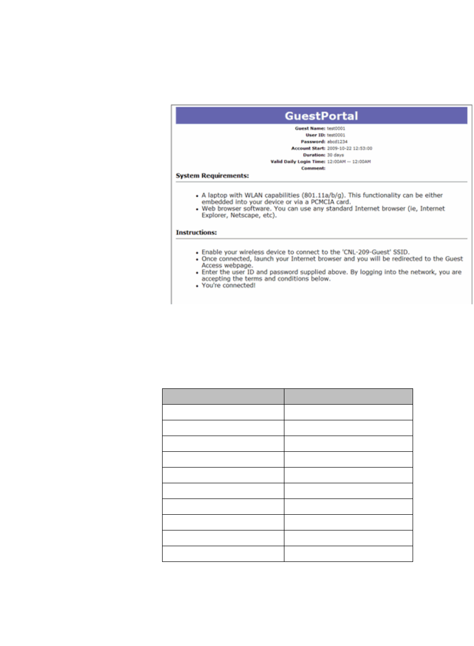
hwc_appendixe.fm
9034530-02, March 2010
HiPath Wireless Controller, Access Points and Convergence Software V7.11, User Guide 535
Default GuestPortal source code
Ticket page
E Default GuestPortal source code
E.1 Ticket page
E.1.1 Placeholders used in the default GuestPortal
ticket page
Placeholder tag Description
!GuestName Guest Name
!GuestComment Guest Comment
!TimeOfDayStart Time-of-day start
!TimeOfDayDuration Time-of-day session duration
!SessionLifeTime Maximum session time
!UserID User ID for the guest
!Password Password for the guest
!SSID SSID to connect to
!AccountActivationTime Account available time
!AccountLifeTime Account life time
Table 49 Default GuestPortal ticket page template placeholders

Default GuestPortal source code
hwc_appendixe.fm
Ticket page
9034530-02, March 2010
536 HiPath Wireless Controller, Access Points and Convergence Software V7.11, User Guide
E.1.2 Default GuestPortal ticket page source code
Note: The GuestPortal account information placeholders used in the html code
are preceded by the ! character.
<HTML>
<HEAD>
<title></title>
<meta content="text/html;charset=utf-8" http-
equiv="Content-Type"/>
</HEAD>
<body style="text-align:center">
<table cellspacing="0" cellpadding="0" border="0"
align="center" width="790">
<tr>
<td style="background-
color:#6666b0;color:white;font-weight:bold;font-
size:30;padding:5px"
align="center" width="790">GuestPortal</td>
</tr>
</table>
<table cellspacing="5" cellpadding="0" border="0"
style="margin:0 auto">
<tr>
<td align="right"><b>Guest Name:</b></td>
<td align="left">!GuestName</td>
</tr>
<tr>
<td align="right"><b>User ID:</b></td>
<td align="left">!UserID</td>
</tr>
<tr>
<td align="right"><b>Password:</b></td>
<td align="left">!Password</td>
</tr>
<tr>

hwc_appendixe.fm
Default GuestPortal source code
Ticket page
9034530-02, March 2010
HiPath Wireless Controller, Access Points and Convergence Software V7.11, User Guide 537
<td align="right"><b>Account Start:</b></td>
<td align="left">!AccountActivationTime</td>
</tr>
<tr>
<td align="right"><b>Duration:</b></td>
<td align="left">!AccountLifeTime</td>
</tr>
<tr>
<td align="right"><b>Valid Daily Login Time:</
b></td>
<td align="left">!TimeOfDayStart --
!TimeOfDayDuration</td>
</tr>
<tr>
<td align="right"><b>Comment:</b></td>
<td align="left">!GuestComment</td>
</tr>
</table>
<div style="width:790px;margin:0 auto;text-align:left">
<b>System Requirements:</b>
<hr width=790 size=2 noshade>
<div style="padding-left:30px">
<ul>
<li>A laptop with WLAN
capabilities (801.11a/b/g). This functionality can be either
embedded into your device or via a PCMCIA card.
<li>Web browser software. You
can use any standard Internet browser (ie, Internet Explorer,
Netscape, etc).
</ul>
</div>
</div>
<div style="width:790px;margin:10px auto;text-
align:left">
<b>Instructions:</b>
<hr width=790 size=2 noshade>
<div style="padding-left:30px;">
<ul>
<li>Enable your wireless device
to connect to the '!SSID' SSID.
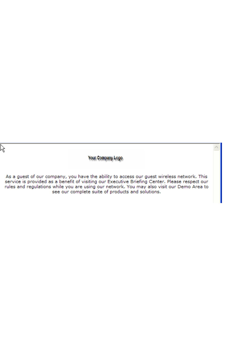
Default GuestPortal source code
hwc_appendixe.fm
GuestPortal sample header page
9034530-02, March 2010
538 HiPath Wireless Controller, Access Points and Convergence Software V7.11, User Guide
<li>Once connected, launch your
Internet browser and you will be redirected to the Guest Access
webpage.
<li>Enter the user ID and
password supplied above. By logging into the network, you are
accepting the terms and conditions below.
<li>You're connected!
</ul>
</div>
</div>
</div>
</body>
</HTML>
E.2 GuestPortal sample header page
Sample header page source code
<HTML><HEAD><TITLE>your company name</TITLE>
<META http-equiv=Content-Type content="text/html;
charset=windows-1252">
<STYLE type=text/css>BODY {
FONT-SIZE: 11px; COLOR: #000000; FONT-FAMILY: Verdana, Arial,
Helvetica, sans-serif
}
TD {
FONT-SIZE: 11px; COLOR: #000000; FONT-FAMILY: Verdana, Arial,
Helvetica, sans-serif
}
H3 {

hwc_appendixe.fm
Default GuestPortal source code
GuestPortal sample header page
9034530-02, March 2010
HiPath Wireless Controller, Access Points and Convergence Software V7.11, User Guide 539
FONT-SIZE: 14px; COLOR: #000066; FONT-FAMILY: Verdana, Arial,
Helvetica, sans-serif
}
</STYLE>
<META content="Microsoft FrontPage 5.0" name=GENERATOR></HEAD>
<BODY>
<SPAN id=0 style="DISPLAY: none;">
<CENTER>
<span id="1" style="DISPLAY: true;"><span id="1">
<img border="0" src="your_logo.gif" width="198" height="49"></
span></span>
</CENTER>
<H3>Wireless Guest Access Login</H3>
<BR>
Please enter the <strong>Username and Password</strong> you
were assigned from the Receptionist. <br>
<INPUT type=hidden value=wba_login
name=fname>
<TABLE cellPadding=3 border=0>
<TBODY>
<TR>
<TD align=right>Username:</TD>
<TD><INPUT maxLength=32 size=15 name=username></TD>
</TR>
<TR>
<TD align=right>Password:</TD>
<TD><INPUT type=password maxLength=32 size=15
name=key></TD>
</TR>
<TR>
<TD align=right colSpan=2>
</TD>
</TR>
</TBODY>
</TABLE>
<br>
For assistance please contact our Operations Center at
555.555.5555
<BR>
</SPAN> <SPAN id=1 style="DISPLAY: true;">
<p align="center"><span id="1">
Default GuestPortal source code
hwc_appendixe.fm
GuestPortal sample footer page
9034530-02, March 2010
540 HiPath Wireless Controller, Access Points and Convergence Software V7.11, User Guide
<img border="0" src="your_logo.gif" width="198" height="49"></
span><br>
<br>
As a guest of our company, you have the ability to access our
guest wireless network.
This service is provided as a benefit of visiting our
Executive Briefing Center.
Please respect our rules and regulations while you are using
our network. You may also visit our Demo Area to see our
complete suite of products and solutions.
</p>
E.3 GuestPortal sample footer page
Sample footer page source code
<html>
<body>
<strong>Terms and Conditions</strong><br>
Access to the information and contents available through
this network are proprietary and confidential. Only authorized
users may access this system.
You may use the information and contents solely in the
manner for which it is intended and authorized. We reserve the
right to monitor your use of this network at any time and in any
manner. Misuse or unauthorized access may result in legal
prosecution.
<BR>
<BR>
<input type="checkbox" name="agree" value="on">
I Agree to the Terms and Conditions <SPAN id=2
style="DISPLAY: none; FONT-WEIGHT: bold; FONT-SIZE: x-small;
COLOR: red">Required</SPAN>
<br>

hwc_appendixe.fm
Default GuestPortal source code
GuestPortal sample footer page
9034530-02, March 2010
HiPath Wireless Controller, Access Points and Convergence Software V7.11, User Guide 541
<br>
<br>
<br>
For assistance please contact the Operations Center at
555.555.5555
</p>
</SPAN>
</BODY></HTML>

Default GuestPortal source code
hwc_appendixe.fm
GuestPortal sample footer page
9034530-02, March 2010
542 HiPath Wireless Controller, Access Points and Convergence Software V7.11, User Guide