Siemens Transportation Systems WAYSIDE Transportation Control System User Manual 290430
Siemens Transportation Systems Transportation Control System 290430
UserManual.wiki
>
Siemens Transportation Systems
>
WAYSIDE User Manual
>
User Manual
Contents
1.
User Manual
2.
Manual Statement for RF Exposur
3.
Replacement Users Manual
User Manual
Navigation menu
Upload a User Manual
Namespaces
Wiki Guide
HTML
PDF
Info
Views
User Manual
Discussion / Help
Navigation
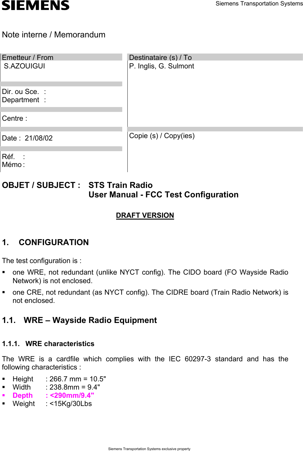
![Réf. : Mémo : Date : 21/08/02 - 4 - Siemens Transportation Systems exclusive property 2.2. Disconnecting coaxial cables or antennas Before disconnecting the coaxial cables or the antennas, the MRAD should be powered off. 2.3. The unused RF output A 50 Ω termination must be set on any unused RF output if no antenna is connected. 3. INSTRUCTIONS FOR USE 3.1. Setting the communication parameters The communication is established with a RS232 link between the computer and the equipment via a terminal. The RS232 is accessed via the DB9 socket [Figure 1; Figure 2] on the front panel. When the terminal is opened on the computer, its parameters have to be defined in the menu Parameters/communications as following: Ports = COM1 or COM 2 (depends on which one was put the RS connection) Transmission speed = 9600 Bits of stop = 1 Stream control = none Data bits = 8 Parity = none 3.1.1. Manual setting Figure 3 : Setting the communication parameters 3.2. Automatic setting The parameters can be automatically defined by opening the file config.trm (provided on a floppy on the example below).](https://usermanual.wiki/Siemens-Transportation-Systems/WAYSIDE.User-Manual/User-Guide-290430-Page-4.png)
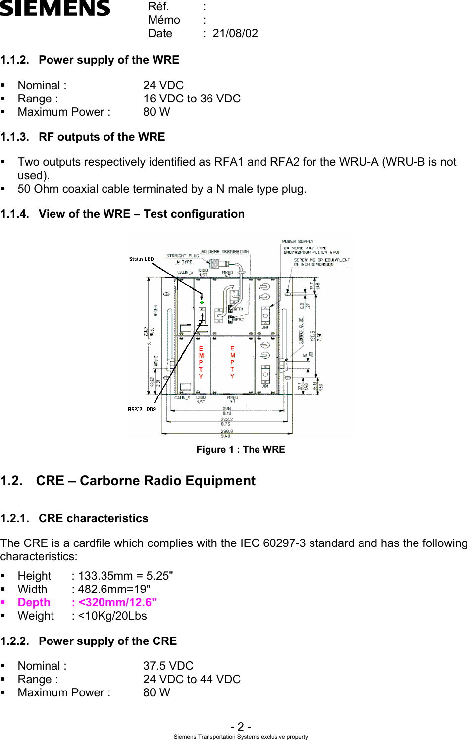
![Réf. : Mémo : Date : 21/08/02 - 6 - Siemens Transportation Systems exclusive property MAIN MENUSELECT TX MODENORMALCHECK MODE /PARAMETERSDOWNLOADFPGALOAD FPGA4.125 ms / 4.125 msPOWER LEVEL : P0, P1 or P2FREQUENCY : 2408, 2416...2472 MHzSWITCH : output RFA1 or RFA2''NOTAVAILABLE''5s / 5sPOWER LEVEL : P0, P1 or P2FREQUENCY : 2408, 2416...2472 MHzSWITCH : output RFA1 or RFA2 Figure 5 : Organization of the menu 3.4.1. Tx Mode The available Tx modes are : • 4.125ms Tx / 4.125ms Rx, • 5s Tx /5s Rx • or normal operation 3.4.1.1. Permanent Mode 4.125ms/4.125ms The MRAD emits during 4.125 ms and stops emitting during the following 4.125ms and so on… Actually, its emission is active during : =+−ssmsµµ80700219.4 3.599 ms and inactive during : =−+ ssmsµµ80700904.3 4.524 ms. The status LED [Figure 1 ; Figure 2] is always on with medium intensity : in fact, it flashes quickly (on during 4.125ms Tx / off during 4.125ms Rx). 3.4.1.2. Permanent Mode 5s/5s The MRAD emits during 5 s and stops emitting during the following 5 s and so on… The status LED [Figure 1 ; Figure 2] is on with high intensity during 5s Tx and off during 5s Rx… 3.4.1.3. Mode normal In normal operation, the MRAD follows a normal radio cycle, its behavior being either a wayside or carborne equipment. However, this mode is not available for the tests.](https://usermanual.wiki/Siemens-Transportation-Systems/WAYSIDE.User-Manual/User-Guide-290430-Page-6.png)