Siemens Transportation Systems WAYSIDE Transportation Control System User Manual 290505
Siemens Transportation Systems Transportation Control System 290505
Contents
- 1. User Manual
- 2. Manual Statement for RF Exposur
- 3. Replacement Users Manual
Replacement Users Manual
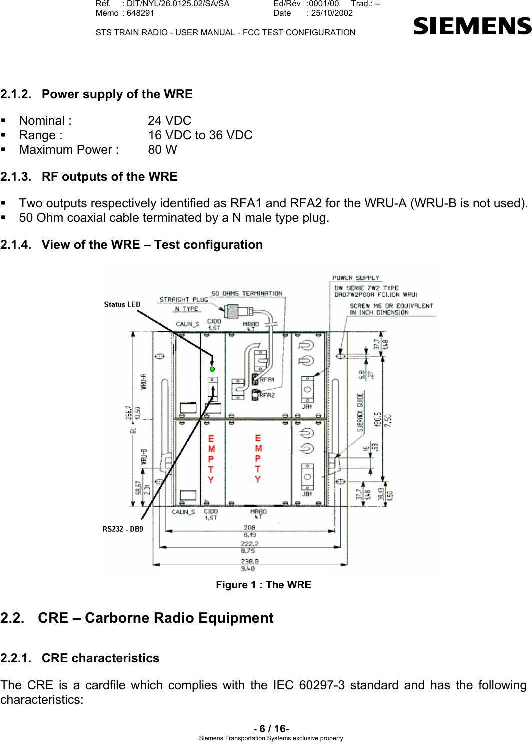
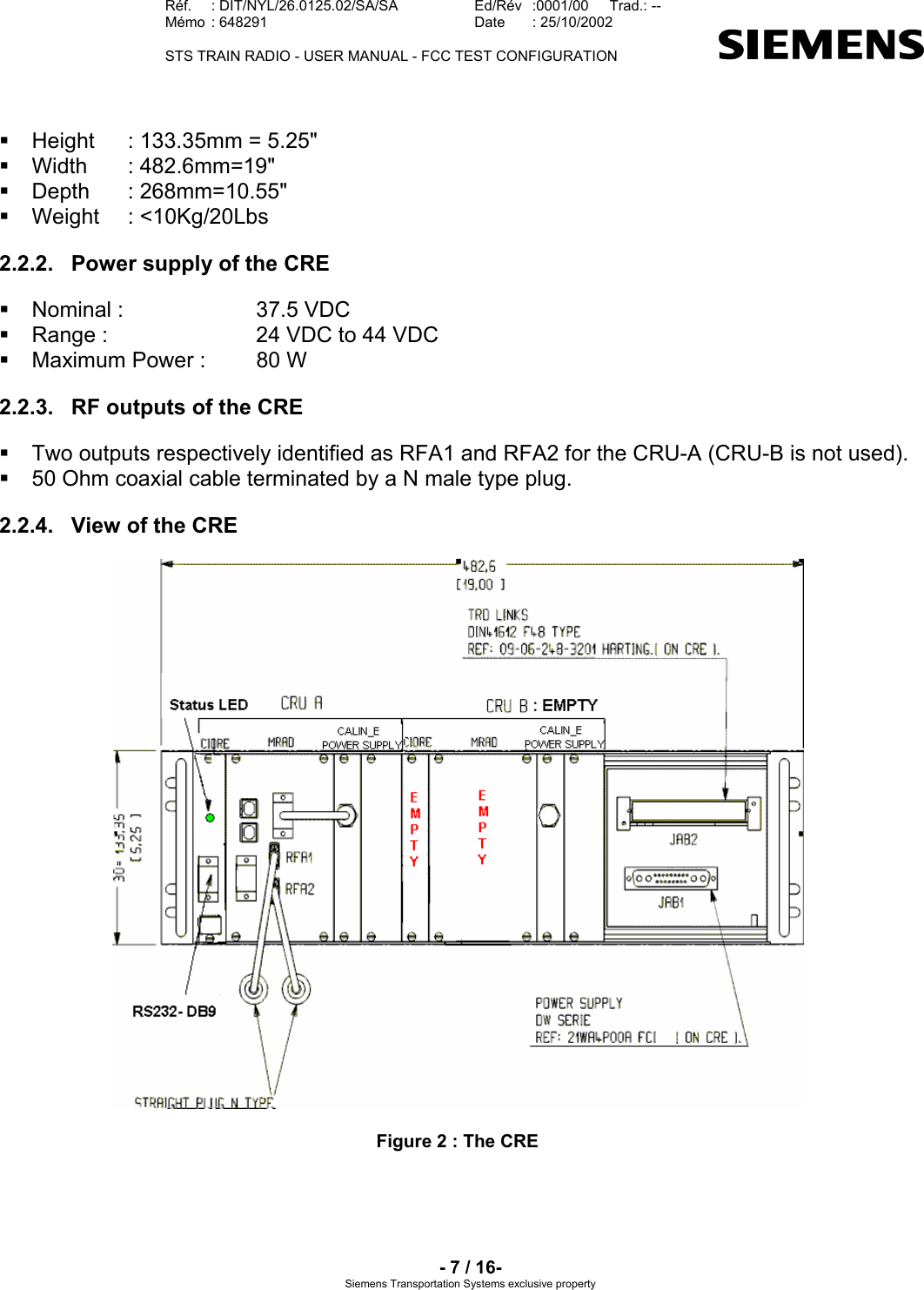
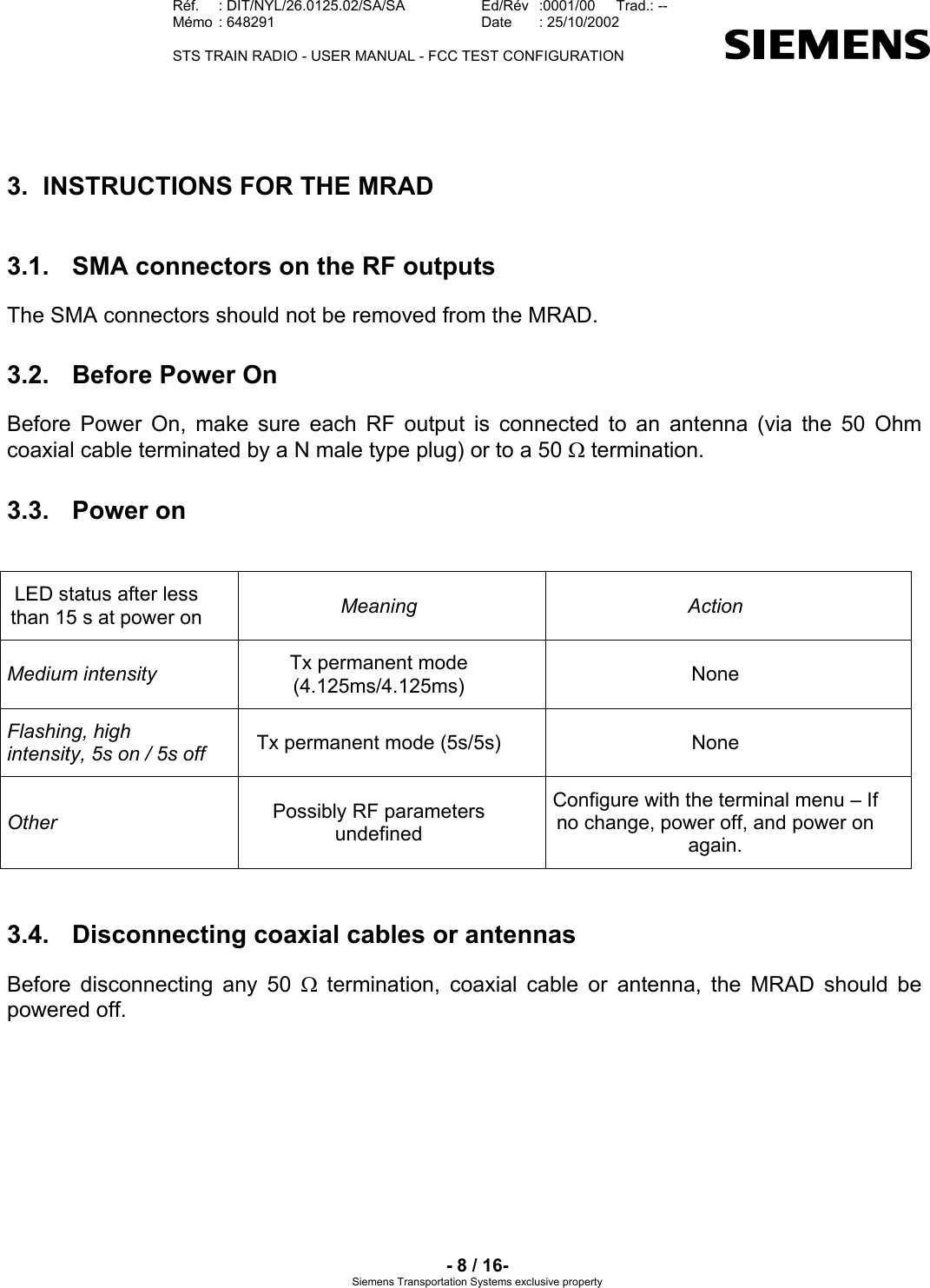
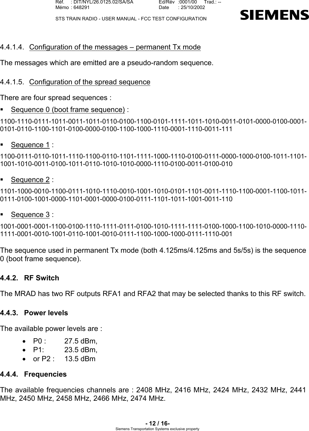
![Réf. : DIT/NYL/26.0125.02/SA/SA Ed/Rév :0001/00 Trad.: -- Mémo : 648291 Date : 25/10/2002 STS TRAIN RADIO - USER MANUAL - FCC TEST CONFIGURATION - 9 / 16- Siemens Transportation Systems exclusive property 4. INSTRUCTIONS FOR USE 4.1. Setting the communication parameters The communication is established with a RS232 link between the computer and the equipment via a terminal. The RS232 is accessed via the DB9 socket [Figure 1; Figure 2] on the front panel. When the terminal is opened on the computer, its parameters have to be defined in the menu Parameters/communications as following : Ports = COM1 or COM 2 (depends on which one was put the RS connection) Transmission speed = 9600 Bits of stop = 1 Stream control = none Data bits = 8 Parity = none 4.1.1. Manual setting Figure 3 : Setting the communication parameters](https://usermanual.wiki/Siemens-Transportation-Systems/WAYSIDE.Replacement-Users-Manual/User-Guide-290505-Page-9.png)
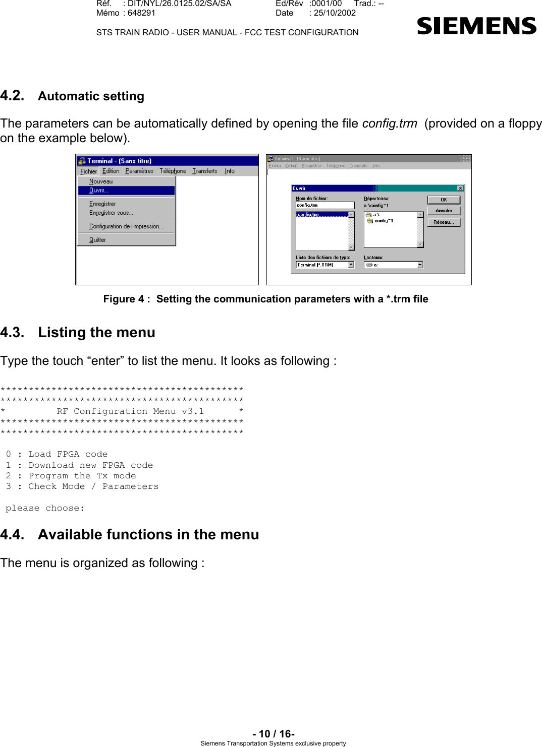
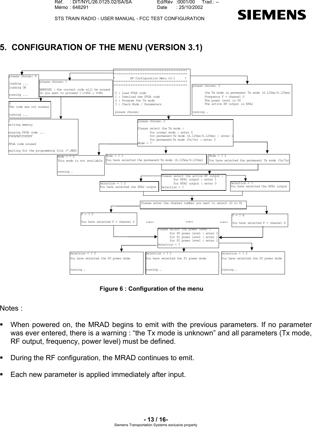
![Réf. : DIT/NYL/26.0125.02/SA/SA Ed/Rév :0001/00 Trad.: -- Mémo : 648291 Date : 25/10/2002 STS TRAIN RADIO - USER MANUAL - FCC TEST CONFIGURATION - 11 / 16- Siemens Transportation Systems exclusive property MAIN MENUSELECT TX MODENORMALCHECK MODE/PARAMETERSDOWNLOADFPGALOAD FPGA4.125 ms / 4.125 msPOWER LEVEL : P0, P1 or P2CHANNEL : 0, 1, 2, 3, 4, 5, 6, 7 or 8SWITCH : output RFA1 or RFA2''NOTAVAILABLE''5s / 5sPOWER LEVEL : P0, P1 or P2SWITCH : output RFA1 or RFA2CHANNEL : 0, 1, 2, 3, 4, 5, 6, 7 or 8 Figure 5 : Organization of the menu 4.4.1. Tx Mode The available Tx modes are : • 4.125ms Tx / 4.125ms Rx, • 5s Tx /5s Rx • or normal operation 4.4.1.1. Permanent Mode 4.125ms/4.125ms The MRAD emits during 4.125 ms and stops emitting during the following 4.125ms and so on… Actually, its emission is active during : =+−ssmsµµ80700219.4 3.599 ms and inactive during : =−+ ssmsµµ80700904.3 4.524 ms. The status LED [Figure 1; Figure 2] is always on with medium intensity : in fact, it flashes quickly (on during 4.125ms Tx / off during 4.125ms Rx). 4.4.1.2. Permanent Mode 5s/5s The MRAD emits during 5 s and stops emitting during the following 5 s and so on… The status LED [Figure 1 ; Figure 2] is on with high intensity during 5s Tx and off during 5s Rx… 4.4.1.3. Mode normal In normal operation, the MRAD follows a normal radio cycle, its behavior being either a wayside or carborne equipment. However, this mode is not available for the tests.](https://usermanual.wiki/Siemens-Transportation-Systems/WAYSIDE.Replacement-Users-Manual/User-Guide-290505-Page-11.png)