Siemens Transportation Systems WAYSIDE Transportation Control System User Manual 290505
Siemens Transportation Systems Transportation Control System 290505
Contents
- 1. User Manual
- 2. Manual Statement for RF Exposur
- 3. Replacement Users Manual
Replacement Users Manual

Siemens Transportation Systems exclusive property
Réf. : DIT/NYL/26.0125.02/SA/SA
Ed/Rév : 0001/00
Traduction : --
Mémo : 648291
Date : 25/10/2002
Projet / Project Arborescence / Technical number
NYL
Canarsie Line CBTC System
Contract S-32701
Type de document / Type of document
USER MANUAL
TITRE / TITLE
STS TRAIN RADIO - USER MANUAL - FCC TEST
CONFIGURATION
Mots clés descripteurs / Descriptors
Rédacteur / Author Nombre de pages / Number of pages
S. AZOUIGUI 16
APPROBATION / APPROVAL
Nom / Name Fonction / Function Date / Date Signature / Signature
S. AZOUIGUI
R. LARDENNOIS
B. CHOCHOIS
Engineer
Radio Manager
Engineer

Réf. : DIT/NYL/26.0125.02/SA/SA Ed/Rév :0001/00 Trad.: --
Mémo : 648291 Date : 25/10/2002
STS TRAIN RADIO - USER MANUAL - FCC TEST CONFIGURATION
- 2 / 16-
Siemens Transportation Systems exclusive property
SUIVI D’EVOLUTIONS / REVISION RECORDS
Edition / Révision
Version number
Date
Date
§ concernés
Affected §
Modification
Change
Justification
Justification
0000 / 00
0001 / 00
13/09/2002
25/10/2002
All
§1
§4.3
§4.4
§4.4.1.4
§4.4.4
§5
new document
new paragraph
RF Configuration
Menu v3.1
Modifications in the
Figure 5 :
Organization of the
menu
Pseudo-random
sequence
Modifications of the
central frequencies
values
Modifications in the
Figure 6 :
Configuration of the
menu
Modifications of the central
frequencies of the
channels
Modifications of the RF
Configuration Menu

Réf. : DIT/NYL/26.0125.02/SA/SA Ed/Rév :0001/00 Trad.: --
Mémo : 648291 Date : 25/10/2002
STS TRAIN RADIO - USER MANUAL - FCC TEST CONFIGURATION
- 3 / 16-
Siemens Transportation Systems exclusive property
TABLE OF CONTENTS
1. PRODUCT MODIFICATIONS .................................................................................................. 5
2. CONFIGURATION....................................................................................................................5
2.1. WRE – WAYSIDE RADIO EQUIPMENT...................................................................................... 5
2.1.1. WRE characteristics......................................................................................................5
2.1.2. Power supply of the WRE ............................................................................................. 6
2.1.3. RF outputs of the WRE ................................................................................................. 6
2.1.4. View of the WRE – Test configuration .......................................................................... 6
2.2. CRE – CARBORNE RADIO EQUIPMENT.................................................................................... 6
2.2.1. CRE characteristics ......................................................................................................6
2.2.2. Power supply of the CRE.............................................................................................. 7
2.2.3. RF outputs of the CRE.................................................................................................. 7
2.2.4. View of the CRE............................................................................................................ 7
3. INSTRUCTIONS FOR THE MRAD........................................................................................... 8
3.1. SMA CONNECTORS ON THE RF OUTPUTS................................................................................ 8
3.2. BEFORE POWER ON..............................................................................................................8
3.3. POWER ON............................................................................................................................ 8
3.4. DISCONNECTING COAXIAL CABLES OR ANTENNAS ..................................................................... 8
4. INSTRUCTIONS FOR USE ...................................................................................................... 9
4.1. SETTING THE COMMUNICATION PARAMETERS ........................................................................... 9
4.1.1. Manual setting............................................................................................................... 9
4.2. AUTOMATIC SETTING............................................................................................................ 10
4.3. LISTING THE MENU............................................................................................................... 10
4.4. AVAILABLE FUNCTIONS IN THE MENU...................................................................................... 10
4.4.1. Tx Mode...................................................................................................................... 11
4.4.2. RF Switch.................................................................................................................... 12
4.4.3. Power levels................................................................................................................ 12
4.4.4. Frequencies ................................................................................................................ 12

Réf. : DIT/NYL/26.0125.02/SA/SA Ed/Rév :0001/00 Trad.: --
Mémo : 648291 Date : 25/10/2002
STS TRAIN RADIO - USER MANUAL - FCC TEST CONFIGURATION
- 4 / 16-
Siemens Transportation Systems exclusive property
5. CONFIGURATION OF THE MENU (VERSION 3.1)............................................................... 13
6. DOWNLOADING A NEW FPGA CODE................................................................................. 14
7. GLOSSARY............................................................................................................................ 15
END OF DOCUMENT .................................................................................................................. 16

Réf. : DIT/NYL/26.0125.02/SA/SA Ed/Rév :0001/00 Trad.: --
Mémo : 648291 Date : 25/10/2002
STS TRAIN RADIO - USER MANUAL - FCC TEST CONFIGURATION
- 5 / 16-
Siemens Transportation Systems exclusive property
1. PRODUCT MODIFICATIONS
• Initial version described in the STS Train Radio – User Manual– FCC Test Configuration
DIT/NYL/26.0125.02/SA/SA – 644088 document.
• Version 3.1 :
¾ The central frequencies of the channels have been modified :
From : 2408, 2416, 2424, 2432, 2440, 2448, 2456, 2464, 2472 MHz.
To : 2408, 2416, 2424, 2432, 2441, 2450, 2458, 2466, 2474 MHz.
¾ The power levels have been modifed :
From : P0=27.5 dBm ; P1=17.5 dBm ; P2=7.5 dBm
To : P0=27.5 dBm ; P1=23.5 dBm ; P2=13.5 dBm
2. CONFIGURATION
The test configuration is :
one WRE, not redundant (unlike NYCT config). The CIDO board (FO Wayside Radio
Network) is not enclosed.
one CRE, not redundant (as NYCT config). The CIDRE board (Train Radio Network) is not
enclosed.
2.1. WRE – Wayside Radio Equipment
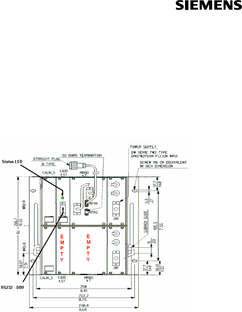
2.1.1. WRE characteristics
The WRE is a cardfile which complies with the IEC 60297-3 standard and has the following
characteristics :
Height : 266.7 mm = 10.5"
Width : 238.8mm = 9.4"
Depth : 236mm=9.3"
Weight : <15Kg/30Lbs
Réf. : DIT/NYL/26.0125.02/SA/SA Ed/Rév :0001/00 Trad.: --
Mémo : 648291 Date : 25/10/2002
STS TRAIN RADIO - USER MANUAL - FCC TEST CONFIGURATION
- 6 / 16-
Siemens Transportation Systems exclusive property
2.1.2. Power supply of the WRE
Nominal : 24 VDC
Range : 16 VDC to 36 VDC
Maximum Power : 80 W
2.1.3. RF outputs of the WRE
Two outputs respectively identified as RFA1 and RFA2 for the WRU-A (WRU-B is not used).
50 Ohm coaxial cable terminated by a N male type plug.
2.1.4. View of the WRE – Test configuration
Figure 1 : The WRE
2.2. CRE – Carborne Radio Equipment
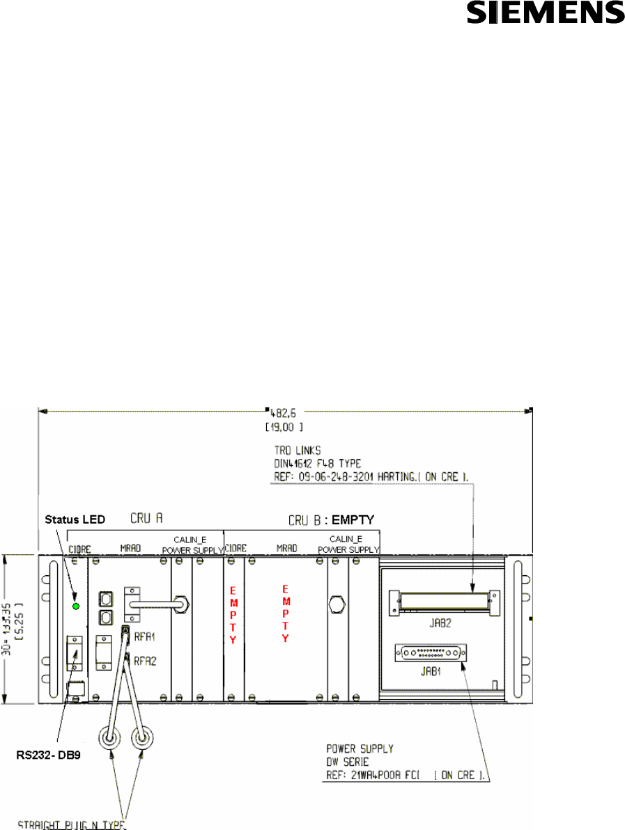
2.2.1. CRE characteristics
The CRE is a cardfile which complies with the IEC 60297-3 standard and has the following
characteristics:
Réf. : DIT/NYL/26.0125.02/SA/SA Ed/Rév :0001/00 Trad.: --
Mémo : 648291 Date : 25/10/2002
STS TRAIN RADIO - USER MANUAL - FCC TEST CONFIGURATION
- 7 / 16-
Siemens Transportation Systems exclusive property
Height : 133.35mm = 5.25"
Width : 482.6mm=19"
Depth : 268mm=10.55"
Weight : <10Kg/20Lbs
2.2.2. Power supply of the CRE
Nominal : 37.5 VDC
Range : 24 VDC to 44 VDC
Maximum Power : 80 W
2.2.3. RF outputs of the CRE
Two outputs respectively identified as RFA1 and RFA2 for the CRU-A (CRU-B is not used).
50 Ohm coaxial cable terminated by a N male type plug.
2.2.4. View of the CRE
Figure 2 : The CRE
Réf. : DIT/NYL/26.0125.02/SA/SA Ed/Rév :0001/00 Trad.: --
Mémo : 648291 Date : 25/10/2002
STS TRAIN RADIO - USER MANUAL - FCC TEST CONFIGURATION
- 8 / 16-
Siemens Transportation Systems exclusive property
3. INSTRUCTIONS FOR THE MRAD
3.1. SMA connectors on the RF outputs
The SMA connectors should not be removed from the MRAD.
3.2. Before Power On
Before Power On, make sure each RF output is connected to an antenna (via the 50 Ohm
coaxial cable terminated by a N male type plug) or to a 50 Ω termination.
3.3. Power on
LED status after less
than 15 s at power on Meaning Action
Medium intensity Tx permanent mode
(4.125ms/4.125ms) None
Flashing, high
intensity, 5s on / 5s off Tx permanent mode (5s/5s) None
Other Possibly RF parameters
undefined
Configure with the terminal menu – If
no change, power off, and power on
again.
3.4. Disconnecting coaxial cables or antennas
Before disconnecting any 50 Ω termination, coaxial cable or antenna, the MRAD should be
powered off.
Réf. : DIT/NYL/26.0125.02/SA/SA Ed/Rév :0001/00 Trad.: --
Mémo : 648291 Date : 25/10/2002
STS TRAIN RADIO - USER MANUAL - FCC TEST CONFIGURATION
- 9 / 16-
Siemens Transportation Systems exclusive property
4. INSTRUCTIONS FOR USE
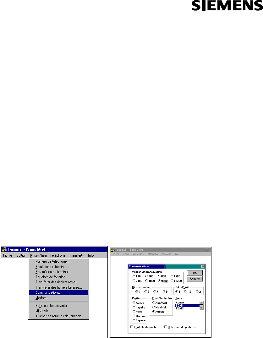
4.1. Setting the communication parameters
The communication is established with a RS232 link between the computer and the equipment
via a terminal. The RS232 is accessed via the DB9 socket [Figure 1; Figure 2] on the front
panel.
When the terminal is opened on the computer, its parameters have to be defined in the menu
Parameters/communications as following :
Ports = COM1 or COM 2 (depends on which one was put the RS connection)
Transmission speed = 9600
Bits of stop = 1
Stream control = none
Data bits = 8
Parity = none
4.1.1. Manual setting
Figure 3 : Setting the communication parameters
Réf. : DIT/NYL/26.0125.02/SA/SA Ed/Rév :0001/00 Trad.: --
Mémo : 648291 Date : 25/10/2002
STS TRAIN RADIO - USER MANUAL - FCC TEST CONFIGURATION
- 10 / 16-
Siemens Transportation Systems exclusive property
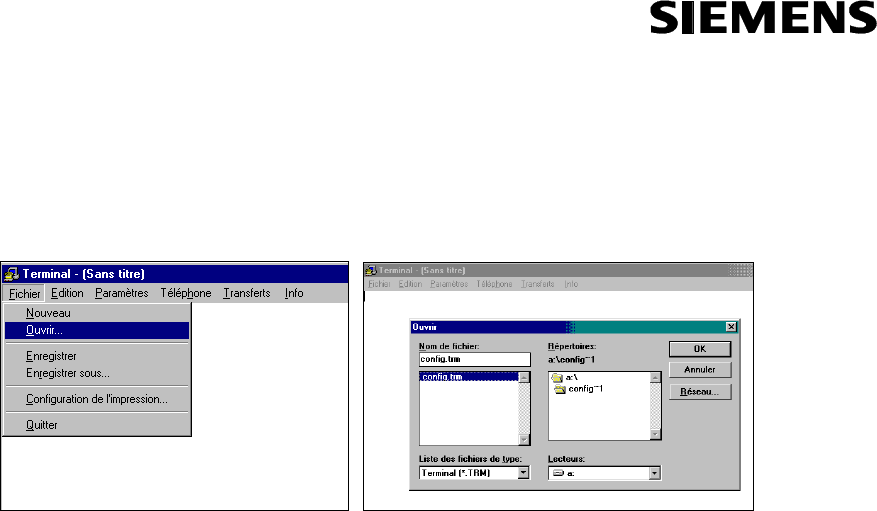
4.2. Automatic setting
The parameters can be automatically defined by opening the file config.trm (provided on a floppy
on the example below).
Figure 4 : Setting the communication parameters with a *.trm file
4.3. Listing the menu
Type the touch “enter” to list the menu. It looks as following :
*******************************************
*******************************************
* RF Configuration Menu v3.1 *
*******************************************
*******************************************
0 : Load FPGA code
1 : Download new FPGA code
2 : Program the Tx mode
3 : Check Mode / Parameters
please choose:
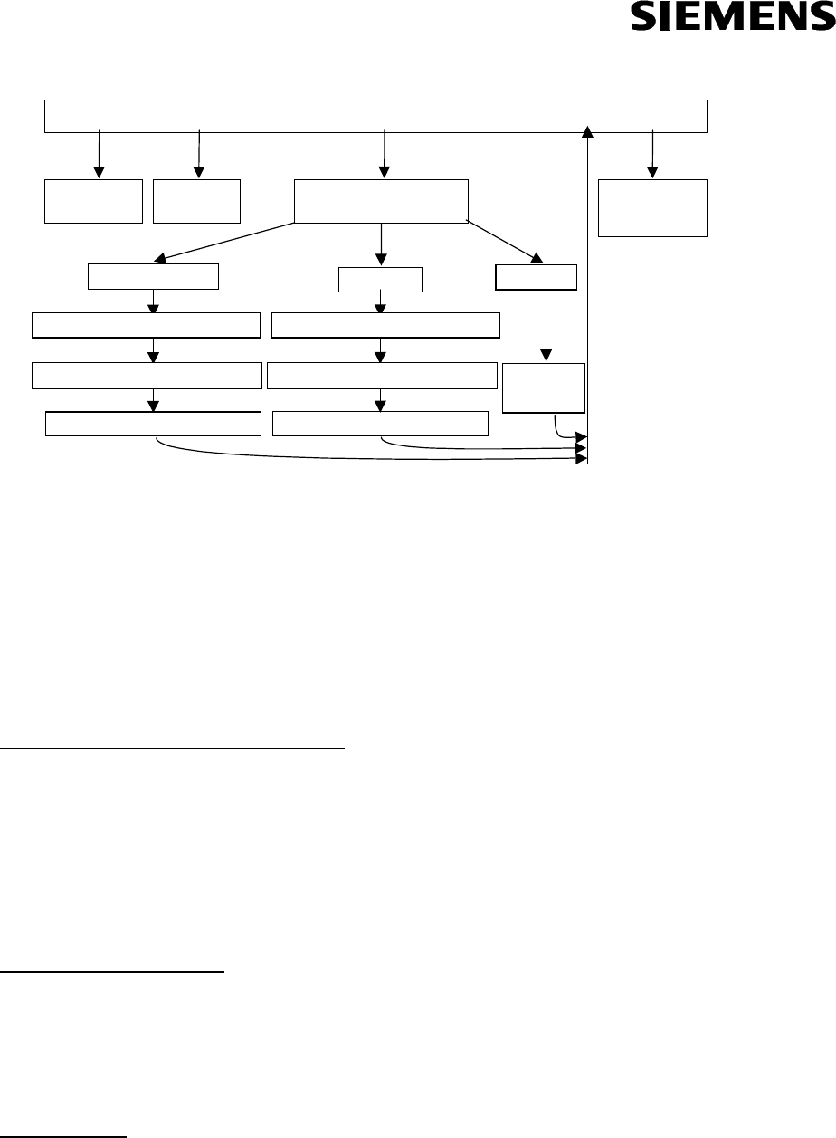
4.4. Available functions in the menu
The menu is organized as following :
Réf. : DIT/NYL/26.0125.02/SA/SA Ed/Rév :0001/00 Trad.: --
Mémo : 648291 Date : 25/10/2002
STS TRAIN RADIO - USER MANUAL - FCC TEST CONFIGURATION
- 11 / 16-
Siemens Transportation Systems exclusive property
MAIN MENU
SELECT TX MODE
NORMAL
CHECK MODE
/
PARAMETERS
DOWNLOAD
FPG
A
LOAD FPGA
4.125 ms / 4.125 ms
POWER LEVEL : P0, P1 or P2
CHANNEL : 0, 1, 2, 3, 4, 5, 6, 7 or 8
SWITCH : output RFA1 or RFA2
''NOT
AVAILABLE''
5s / 5s
POWER LEVEL : P0, P1 or P2
SWITCH : output RFA1 or RFA2
CHANNEL : 0, 1, 2, 3, 4, 5, 6, 7 or 8
Figure 5 : Organization of the menu
4.4.1. Tx Mode
The available Tx modes are :
• 4.125ms Tx / 4.125ms Rx,
• 5s Tx /5s Rx
• or normal operation
4.4.1.1. Permanent Mode 4.125ms/4.125ms
The MRAD emits during 4.125 ms and stops emitting during the following 4.125ms and so on…
Actually, its emission is active during :
=
+
−
ssms
µ
µ
80700219.4 3.599 ms and inactive during :
=−+ ssms
µ
µ
80700904.3 4.524 ms.
The status LED [Figure 1; Figure 2] is always on with medium intensity : in fact, it flashes
quickly (on during 4.125ms Tx / off during 4.125ms Rx).
4.4.1.2. Permanent Mode 5s/5s
The MRAD emits during 5 s and stops emitting during the following 5 s and so on…
The status LED [Figure 1 ; Figure 2] is on with high intensity during 5s Tx and off during 5s
Rx…
4.4.1.3. Mode normal
In normal operation, the MRAD follows a normal radio cycle, its behavior being either a
wayside or carborne equipment. However, this mode is not available for the tests.

Réf. : DIT/NYL/26.0125.02/SA/SA Ed/Rév :0001/00 Trad.: --
Mémo : 648291 Date : 25/10/2002
STS TRAIN RADIO - USER MANUAL - FCC TEST CONFIGURATION
- 12 / 16-
Siemens Transportation Systems exclusive property
4.4.1.4. Configuration of the messages – permanent Tx mode
The messages which are emitted are a pseudo-random sequence.
4.4.1.5. Configuration of the spread sequence
There are four spread sequences :
Sequence 0 (boot frame sequence) :
1100-1110-0111-1011-0011-1011-0110-0100-1100-0101-1111-1011-1010-0011-0101-0000-0100-0001-
0101-0110-1100-1101-0100-0000-0100-1100-1000-1110-0001-1110-0011-111
Sequence 1 :
1100-0111-0110-1011-1110-1100-0110-1101-1111-1000-1110-0100-0111-0000-1000-0100-1011-1101-
1001-1010-0011-0100-1011-0110-1010-1010-0000-1110-0100-0011-0100-010
Sequence 2 :
1101-1000-0010-1100-0111-1010-1110-0010-1001-1010-0101-1101-0011-1110-1100-0001-1100-1011-
0111-0100-1001-0000-1101-0001-0000-0100-0111-1101-1011-1001-0011-110
Sequence 3 :
1001-0001-0001-1100-0100-1110-1111-0111-0100-1010-1111-1111-0100-1000-1100-1010-0000-1110-
1111-0001-0010-1001-0110-1001-0010-0111-1100-1000-1000-0111-1110-001
The sequence used in permanent Tx mode (both 4.125ms/4.125ms and 5s/5s) is the sequence
0 (boot frame sequence).
4.4.2. RF Switch
The MRAD has two RF outputs RFA1 and RFA2 that may be selected thanks to this RF switch.
4.4.3. Power levels
The available power levels are :
• P0 : 27.5 dBm,
• P1: 23.5 dBm,
• or P2 : 13.5 dBm
4.4.4. Frequencies
The available frequencies channels are : 2408 MHz, 2416 MHz, 2424 MHz, 2432 MHz, 2441
MHz, 2450 MHz, 2458 MHz, 2466 MHz, 2474 MHz.
Réf. : DIT/NYL/26.0125.02/SA/SA Ed/Rév :0001/00 Trad.: --
Mémo : 648291 Date : 25/10/2002
STS TRAIN RADIO - USER MANUAL - FCC TEST CONFIGURATION
- 13 / 16-
Siemens Transportation Systems exclusive property
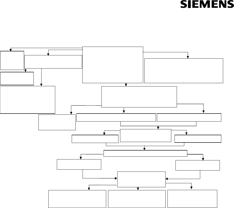
5. CONFIGURATION OF THE MENU (VERSION 3.1)
please choose: 2
Please select the Tx mode :
for normal mode : enter 0
for permanent Tx mode (4.125ms/4.125ms) : enter 1
for permanent Tx mode (5s/5s) : enter 2
Mode = ?
Mode = ? 0
This mode is not availabl
e
running …
please choose: 3
th
e
Tx mode is permanent Tx mode (4.125ms/4.125ms)
Frequency F = channel 0
The power level is P0
The active RF output is RFA2
running …
please choose: 0
loading ...
loading OK
running ...
please choose: 1
WARNING : the current code will be erase
d
Do you want to proceed ? 1=YES ; 0=NO
0
The code was not erase
d
running ...
*
******************************************
*
******************************************
*
RF Configuration Menu v3.1 *
*
******************************************
*
******************************************
0 : Load FPGA cod
e
1 : Download new FPGA cod
e
2 : Program th
e
Tx mode
3 : Check Mode / Parameters
please choose:
Please select the active RF output :
for RFA1 output : enter 1
for RFA2 output : enter 0
Selection = ?
Selection = ? 0
You have selected the RFA2 output
Please enter the channel number you want to select (0 to 8)
Mode = ? 1
You have selected the permanent Tx mode (4.125ms/4.125ms)
1
writing memor
y
erasing FPGA code ...
F9FAFBFCFDFEFF
FPGA code erase
d
waiting for the programming file (*.HEX)
Selection = ?
You have selected the RFA1 output
Mode = ? 2
You have selected the permanent Tx mode (5s/5s)
F = ? 0
You have selected F = channel 0
Please select the power level :
for P0 power level : enter 0
for P1 power level : enter 1
for P2 power level : enter 2
Selection = ?
Selection = ? 0
You have selected the P0 power mod
e
running …
F = ? 8
You have selected F = channel 8
…… …………
Selection = ? 1
You have selected the P1 power mode
running …
Selection = ? 2
You have selected the P2 power mod
e
running …
Figure 6 : Configuration of the menu
Notes :
When powered on, the MRAD begins to emit with the previous parameters. If no parameter
was ever entered, there is a warning : “the Tx mode is unknown” and all parameters (Tx mode,
RF output, frequency, power level) must be defined.
During the RF configuration, the MRAD continues to emit.
Each new parameter is applied immediately after input.
Réf. : DIT/NYL/26.0125.02/SA/SA Ed/Rév :0001/00 Trad.: --
Mémo : 648291 Date : 25/10/2002
STS TRAIN RADIO - USER MANUAL - FCC TEST CONFIGURATION
- 14 / 16-
Siemens Transportation Systems exclusive property
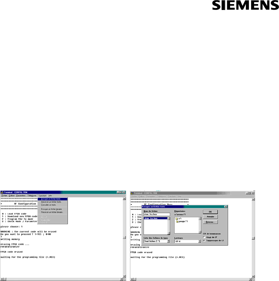
6. DOWNLOADING A NEW FPGA CODE
To download a new FPGA code, the menu 1 (“Download a new FPGA code”) has to be chosen
and confirmed. Then, the FPGA code is erased and the menu waits for a programming file
*.hex.
1
writing memory
erasing FPGA code ...
F9FAFBFCFDFEFF
FPGA code erased
waiting for the programming file (*.HEX)
The programming file is in : A:\Programming_FPGA\ckmr_fcc.hex. It has to be sent as following:
Figure 7 : Downloading a new FPGA code
Note : The programming lasts about 5 minutes.

Réf. : DIT/NYL/26.0125.02/SA/SA Ed/Rév :0001/00 Trad.: --
Mémo : 648291 Date : 25/10/2002
STS TRAIN RADIO - USER MANUAL - FCC TEST CONFIGURATION
- 15 / 16-
Siemens Transportation Systems exclusive property
7. GLOSSARY
BRAD Radio frequency unit
CALIN_E Carborne power supply
CALIN_S Wayside power supply
CIDO WRD controller
CIDRE Carborne Radio Distribution Unit
CKMR Radio controller board
CRE Carborne Radio Equipment
CRU Carborne Radio Unit
MRAD Radio module
RF Radio Frequency
Rx Reception
Tx Transmission
WRE Wayside radio equipment
WRU Wayside Radio Unit

Réf. : DIT/NYL/26.0125.02/SA/SA Ed/Rév :0001/00 Trad.: --
Mémo : 648291 Date : 25/10/2002
STS TRAIN RADIO - USER MANUAL - FCC TEST CONFIGURATION
- 16 / 16-
Siemens Transportation Systems exclusive property
END OF DOCUMENT