Siemens Transportation Systems WAYSIDE1 Transportation Control System User Manual Sp cification G n rique New York

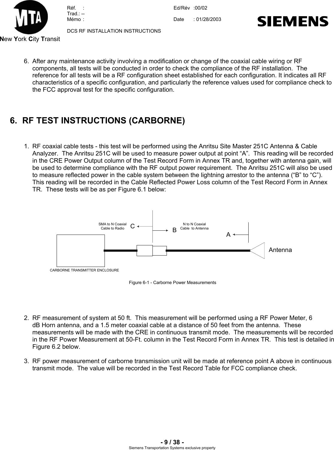
Siemens Transportation Systems Transportation Control System Sp cification G n rique New York

Contents

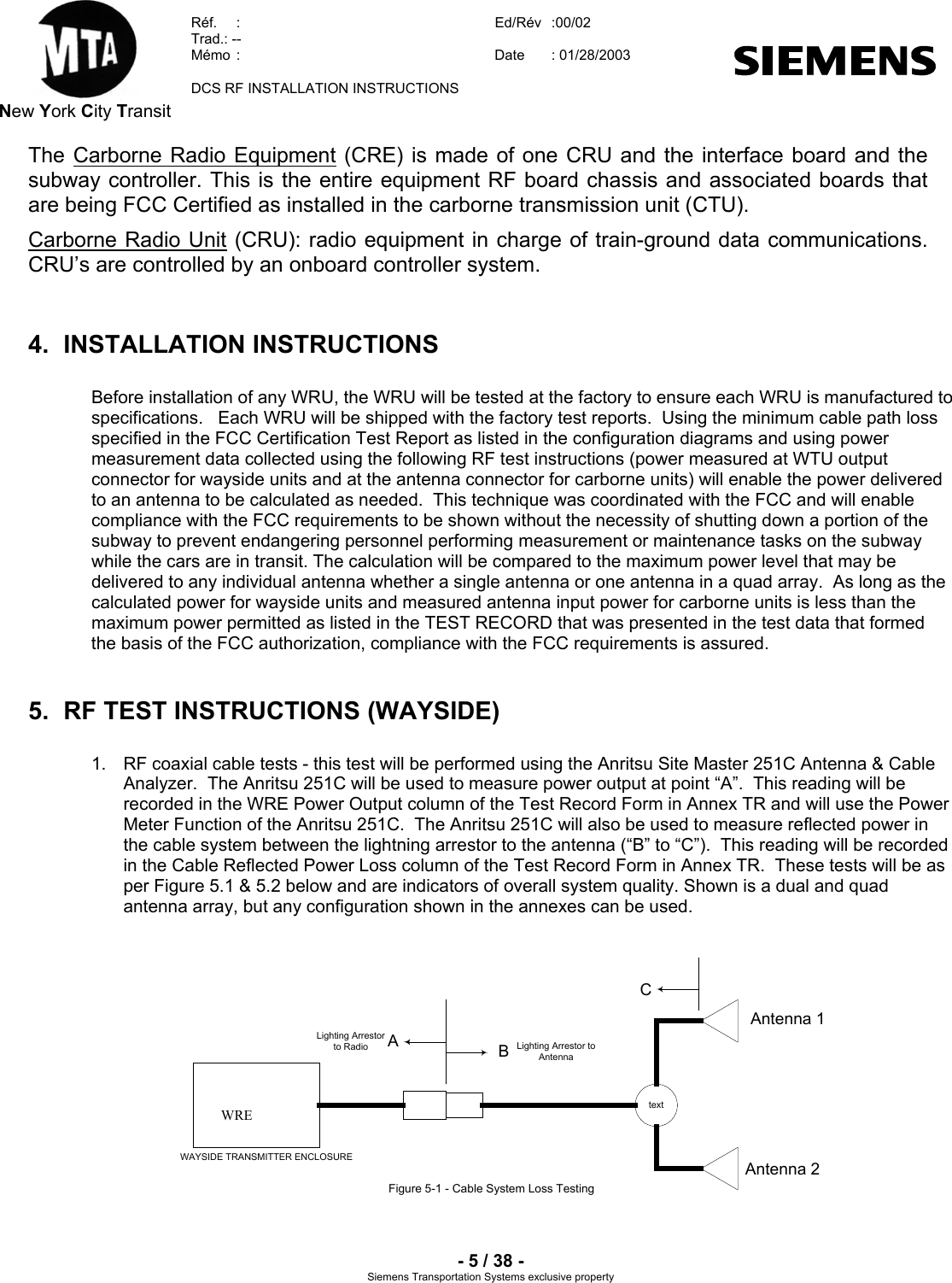
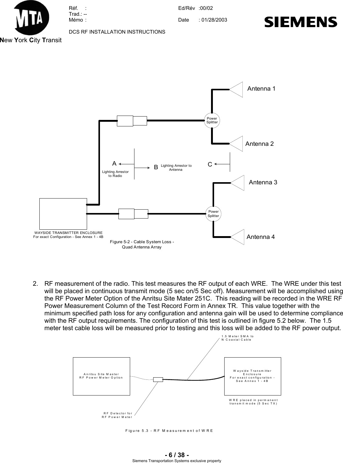
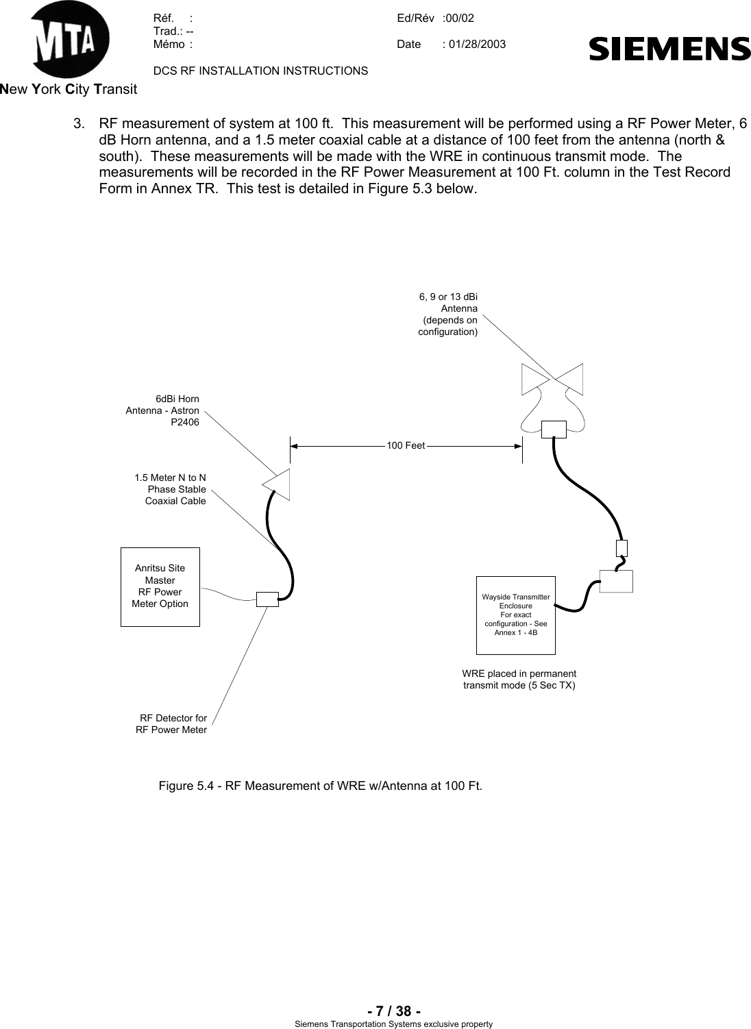
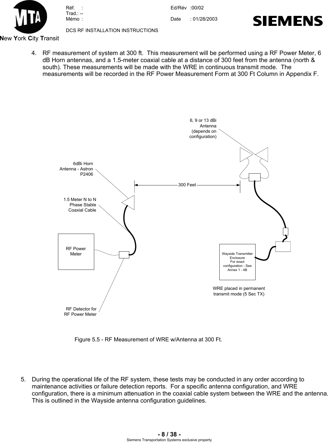
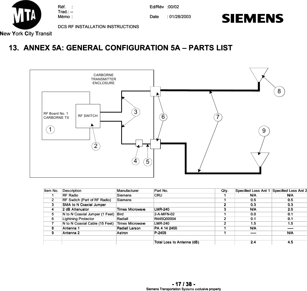
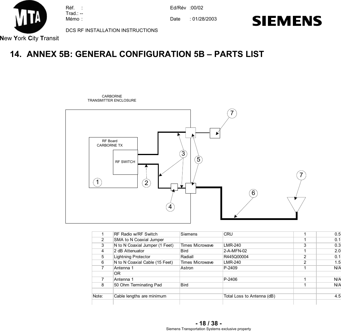
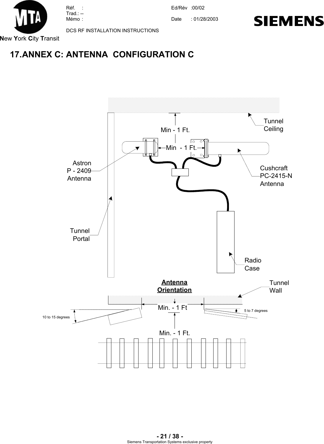
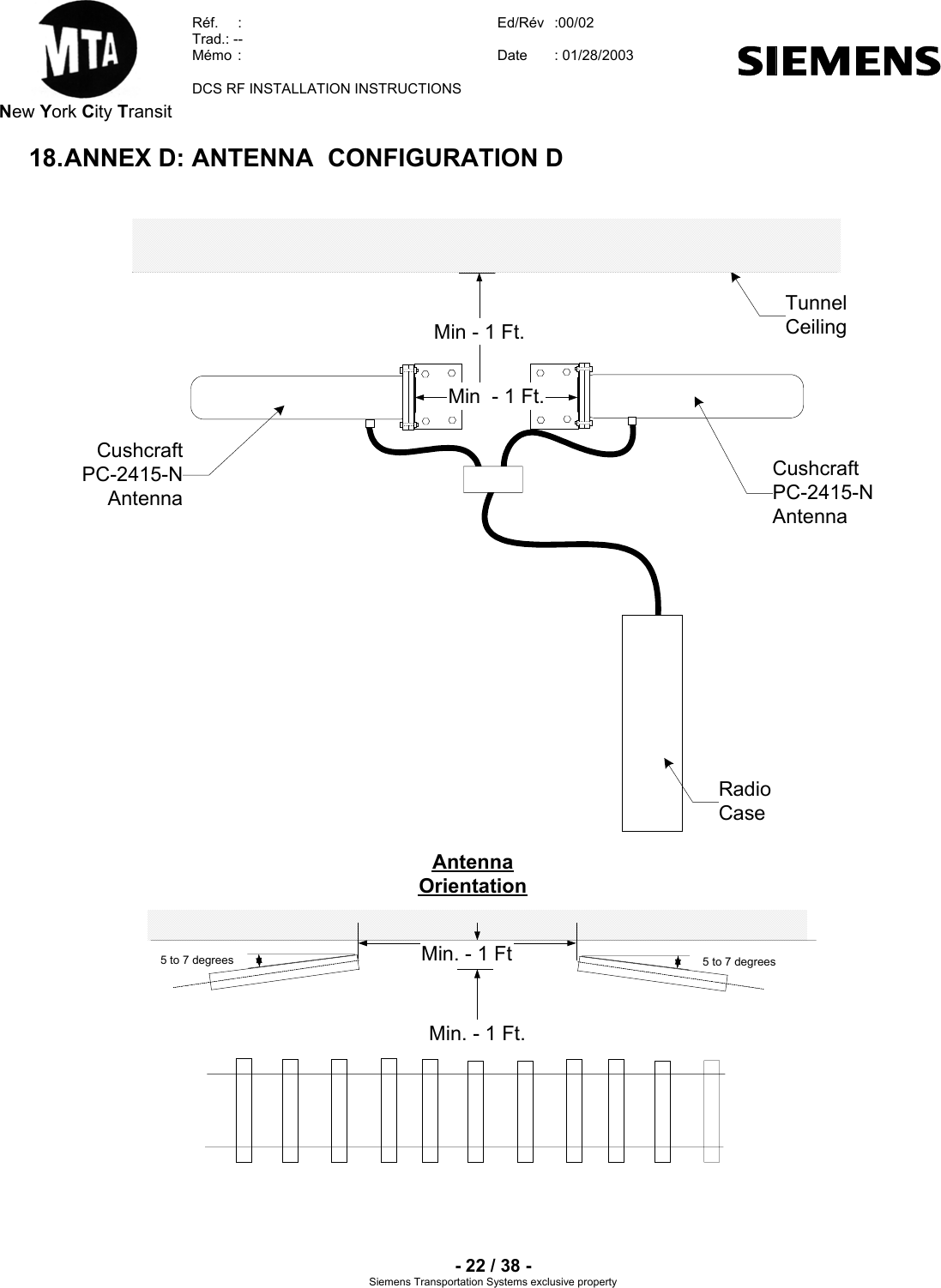
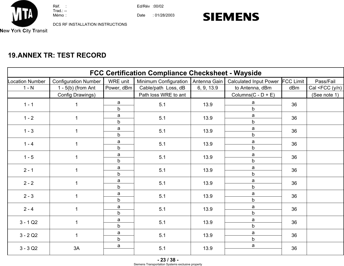
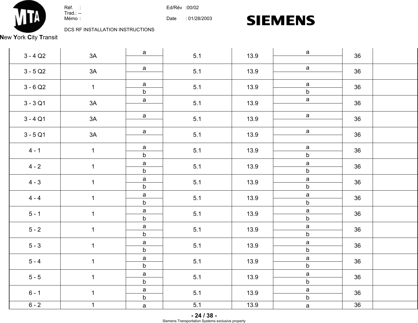
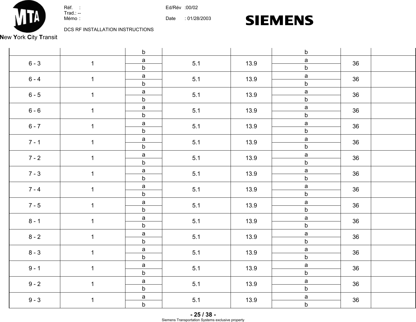
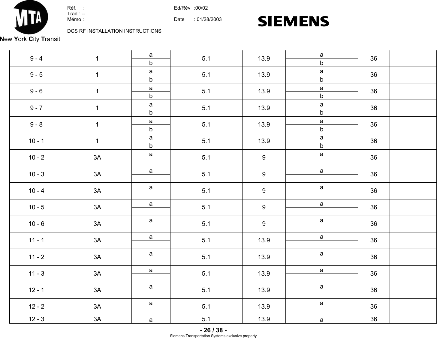
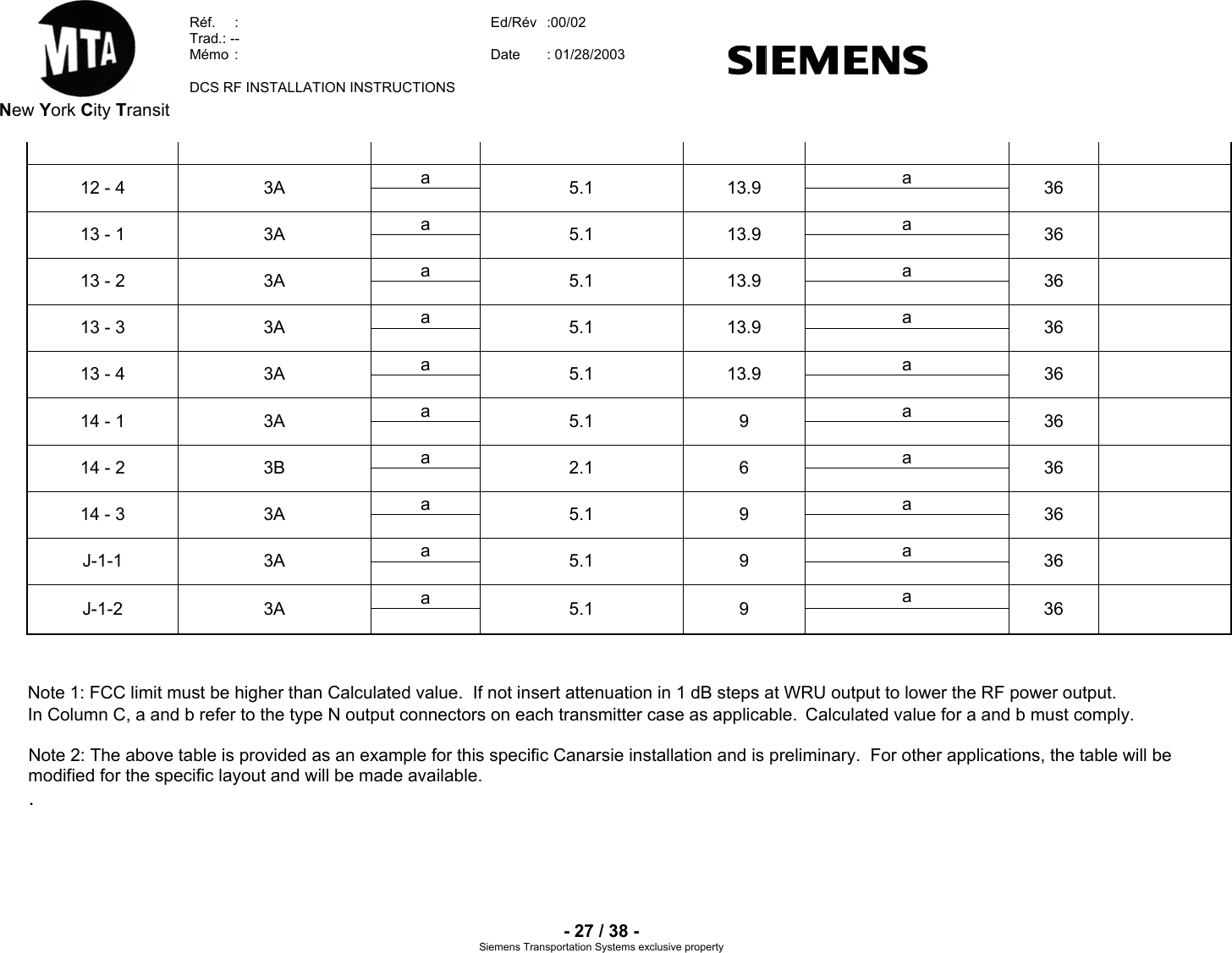
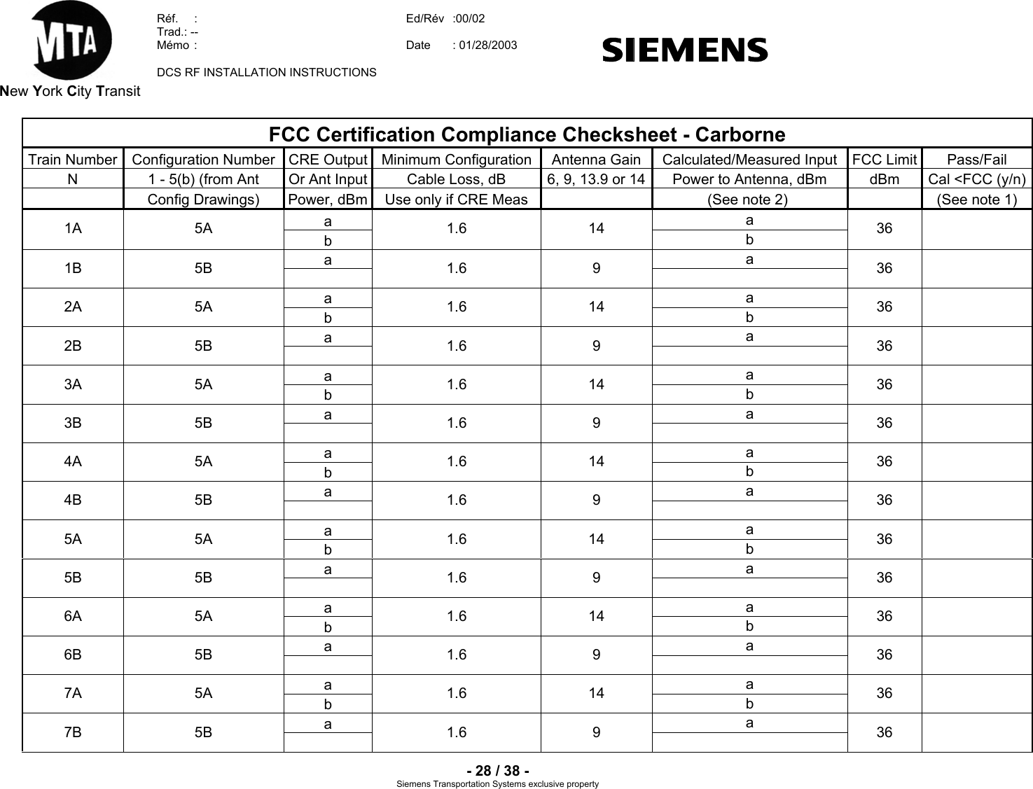
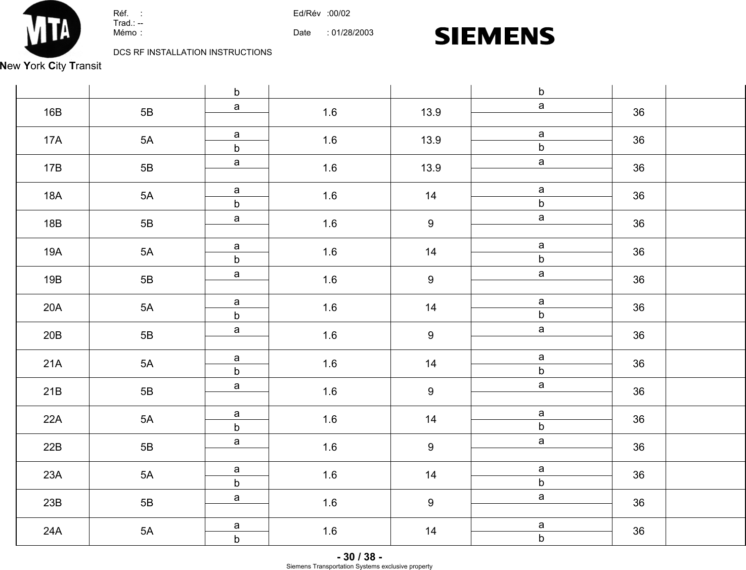
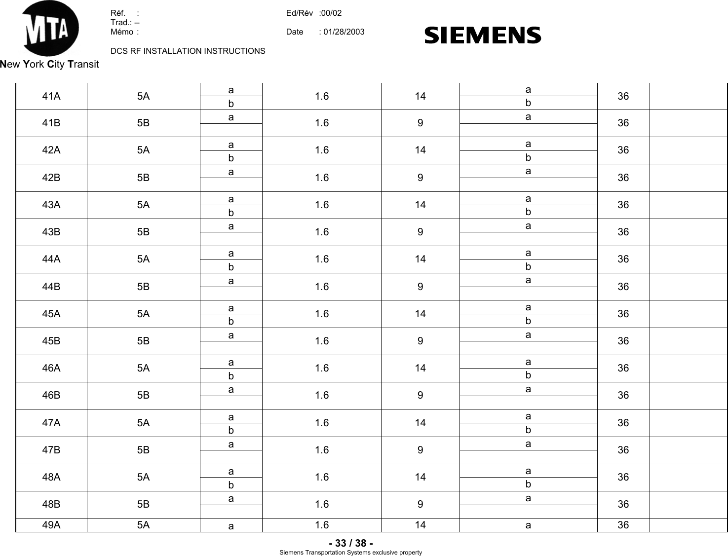
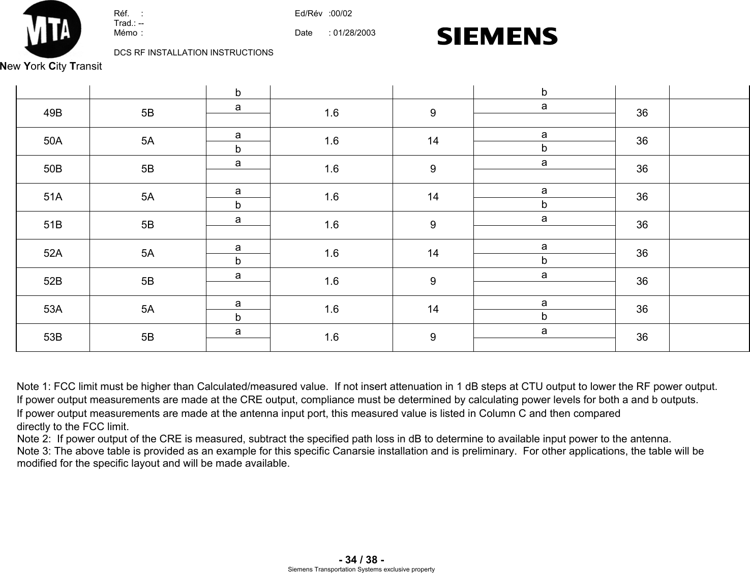
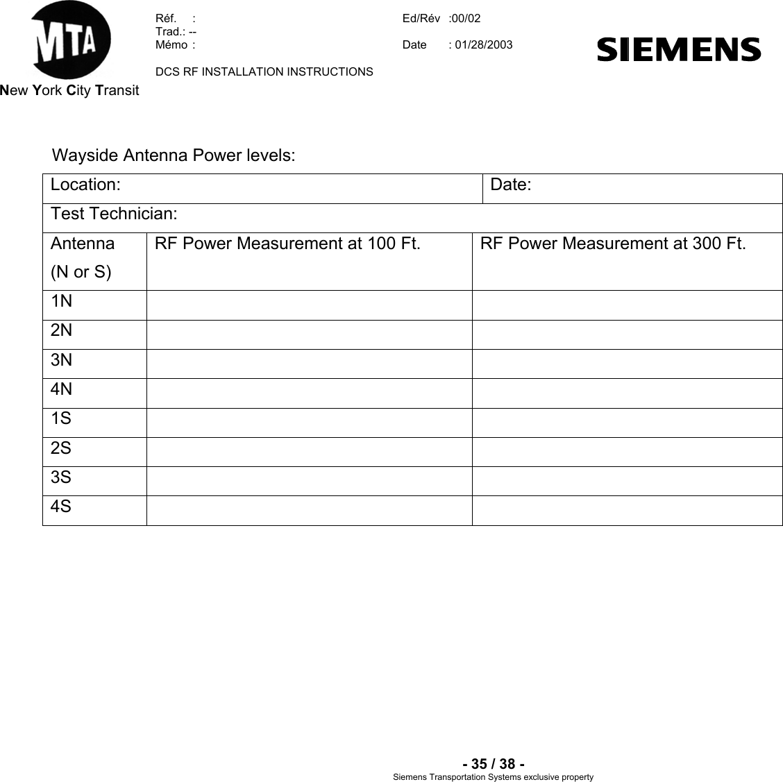
installation instructions

 Siemens Transportation Systems exclusive property   New York City Transit Réf.   :   Ed/Rév : 00/02  Traduction :  --  Mémo :  Date : 01/28/2003     Projet / Project   Arborescence / Technical number  NYL  Canarsie Line CBTC System Contract S-32701           Type de document / Type of document    TITRE / TITLE  DCS RF INSTALLATION INSTRUCTIONS   Mots clés descripteurs / Descriptors        Rédacteur / Author    Nombre de pages / Number of pages R. Zmudzinski   38   APPROBATION / APPROVAL  Nom / Name Fonction / Function Date / Date Signature / Signature
 New York City Transit  Réf.  :  Ed/Rév   :00/02  Trad.: --  Mémo  :  Date  : 01/28/2003    DCS RF INSTALLATION INSTRUCTIONS    - 2 / 38 - Siemens Transportation Systems exclusive property SUIVI D’EVOLUTIONS / REVISION RECORDS  Edition / Révision Version number Date Date § concernés Affected § Modification Change Justification Justification 00/00DRAFT   00/01   00/02 Dec 10th  2002  Jan 13th 2003  Jan 28th 2003 -- --  First Issue   Address internal comments   Additional internal comments addressed
 New York City Transit  Réf.  :  Ed/Rév   :00/02  Trad.: --  Mémo  :  Date  : 01/28/2003    DCS RF INSTALLATION INSTRUCTIONS    - 3 / 38 - Siemens Transportation Systems exclusive property TABLE OF CONTENTS  1. SCOPE ..................................................................................................................................... 4 2. RELATED DOCUMENTS......................................................................................................... 4 3. TERMINOLOGY ....................................................................................................................... 4 3.1. ACRONYMS AND ABBREVIATIONS............................................................................................. 4 3.2. DEFINITION ........................................................................................................................... 4 4. INSTALLATION INSTRUCTIONS............................................................................................ 5 5.  RF TEST INSTRUCTIONS (WAYSIDE) ................................................................................... 5 6.  RF TEST INSTRUCTIONS (CARBORNE) ............................................................................... 9 ANNEX 1: GENRAL CONFIGURATION – PARTS LIST CONFIGURATION  1.......................... 11 ANNEX 2 – GENERAL CONFIGURATION – PARTS LIST CONFIGURATION 2....................... 12 ANNEX 3A: GENERAL CONFIGURATION – PARTS LIST CONFIGURATION 3A ................... 13 ANNEX 3B: GENERAL CONFIGURATION – PARTS LSIT CONFIGURATION 3B ................... 14 ANNEX 4A: GENERAL CONFIGURATION – PARTS LIST CONFIGURATION 4A ................... 15 ANNEX 4B: GENERAL CONFIGURATION – PARTS LIST CONFIGURATION 4B ................... 16 13.  ANNEX 5A: GENERAL CONFIGURATION – PARTS LIST CONFIGURATION 5A .......... 17 14.  ANNEX 5B: GENERAL CONFIGURATION – PARTS LIST CONFIGURATION 5B .......... 18 15.  ANNEX A: ANTENNA  CONFIGURATION A ..................................................................... 19 16.  ANNEX B: ANTENNA  CONFIGURATION B ..................................................................... 20 17.  ANNEX C: ANTENNA  CONFIGURATION C ..................................................................... 21 18.  ANNEX D: ANTENNA  CONFIGURATION D ..................................................................... 22 19.  ANNEX TR: TEST RECORD............................................................................................... 23
 New York City Transit  Réf.  :  Ed/Rév   :00/02  Trad.: --  Mémo  :  Date  : 01/28/2003    DCS RF INSTALLATION INSTRUCTIONS    - 4 / 38 - Siemens Transportation Systems exclusive property 1. SCOPE The goal of this document is to define the requirements for installation and testing of the Wayside Radio Case.  It also provides the documentation procedure to insure conformance with the Radio Regulatory Authorization requirements 2. RELATED DOCUMENTS STS Radio (WRE) User Manual Anritsu Site Master 251C Cable Tester FCC Interpretation Correspondence 3. TERMINOLOGY 3.1.  Acronyms and abbreviations CBTC:   Communication Based Train Control CRU:    Carborne Radio Unit EIRP:    Emitted Isotropic Radiated Power NYCT:   New York City Transit WRE:    Wayside Radio Equipment, made of two WRUs WRU:    Wayside Radio Unit WCC    Wayside (radio) Cell Controller A WCC is made of two redundant WTU  WTU    Wayside Transmission Unit 3.2. Definitions Wayside Radio Unit (WRU): Chassis containing radio equipment in charge of ground-train data communications. WRUs are controlled by the Wayside Transmission Unit (WTU).  The Wayside Radio Equipment (WRE) is made of either one or two (configuration dependent) redundant WRUs and the interface board to the WTU. This is the entire equipment chassis and associated boards that are being FCC Certified.  Under normal operation, only one RF Board of the WRE is active at a time.  A Wayside Cell Controller (WCC) includes two redundant WTU.
 New York City Transit  Réf.  :  Ed/Rév   :00/02  Trad.: --  Mémo  :  Date  : 01/28/2003    DCS RF INSTALLATION INSTRUCTIONS    - 5 / 38 - Siemens Transportation Systems exclusive property The Carborne Radio Equipment (CRE) is made of one CRU and the interface board and the subway controller. This is the entire equipment RF board chassis and associated boards that are being FCC Certified as installed in the carborne transmission unit (CTU). Carborne Radio Unit (CRU): radio equipment in charge of train-ground data communications. CRU’s are controlled by an onboard controller system.  4. INSTALLATION INSTRUCTIONS Before installation of any WRU, the WRU will be tested at the factory to ensure each WRU is manufactured to specifications.   Each WRU will be shipped with the factory test reports.  Using the minimum cable path loss specified in the FCC Certification Test Report as listed in the configuration diagrams and using power measurement data collected using the following RF test instructions (power measured at WTU output connector for wayside units and at the antenna connector for carborne units) will enable the power delivered to an antenna to be calculated as needed.  This technique was coordinated with the FCC and will enable compliance with the FCC requirements to be shown without the necessity of shutting down a portion of the subway to prevent endangering personnel performing measurement or maintenance tasks on the subway while the cars are in transit. The calculation will be compared to the maximum power level that may be delivered to any individual antenna whether a single antenna or one antenna in a quad array.  As long as the calculated power for wayside units and measured antenna input power for carborne units is less than the maximum power permitted as listed in the TEST RECORD that was presented in the test data that formed the basis of the FCC authorization, compliance with the FCC requirements is assured. 5.  RF TEST INSTRUCTIONS (WAYSIDE) 1.  RF coaxial cable tests - this test will be performed using the Anritsu Site Master 251C Antenna & Cable Analyzer.  The Anritsu 251C will be used to measure power output at point “A”.  This reading will be recorded in the WRE Power Output column of the Test Record Form in Annex TR and will use the Power Meter Function of the Anritsu 251C.  The Anritsu 251C will also be used to measure reflected power in the cable system between the lightning arrestor to the antenna (“B” to “C”).  This reading will be recorded in the Cable Reflected Power Loss column of the Test Record Form in Annex TR.  These tests will be as per Figure 5.1 & 5.2 below and are indicators of overall system quality. Shown is a dual and quad antenna array, but any configuration shown in the annexes can be used.    WAYSIDE TRANSMITTER ENCLOSUREFor exact Configuration - See Annex 1 - 4BtextBACAntenna 1Antenna 2Lighting Arrestorto Radio Lighting Arrestor toAntennaFigure 5-1 - Cable System Loss TestingWRE
 New York City Transit  Réf.  :  Ed/Rév   :00/02  Trad.: --  Mémo  :  Date  : 01/28/2003    DCS RF INSTALLATION INSTRUCTIONS    - 6 / 38 - Siemens Transportation Systems exclusive property     WAYSIDE TRANSMITTER ENCLOSUREFor exact Configuration - See Annex 1 - 4BPowerSplitterBACAntenna 3Antenna 4Lighting Arrestorto RadioLighting Arrestor toAntennaFigure 5-2 - Cable System Loss -Quad Antenna ArrayPowerSplitterAntenna 1Antenna 2     2.  RF measurement of the radio. This test measures the RF output of each WRE.  The WRE under this test will be placed in continuous transmit mode (5 sec on/5 Sec off). Measurement will be accomplished using the RF Power Meter Option of the Anritsu Site Mater 251C.  This reading will be recorded in the WRE RF Power Measurement Column of the Test Record Form in Annex TR.  This value together with the minimum specified path loss for any configuration and antenna gain will be used to determine compliance with the RF output requirements. The configuration of this test is outlined in figure 5.2 below.  The 1.5 meter test cable loss will be measured prior to testing and this loss will be added to the RF power output.  A n ritsu  S ite  M a s te rRF Power Meter OptionW ayside Transm itterEnclosureFor exact configuration -See Annex 1 - 4BW R E placed in perm anenttransm it m ode (5 Sec TX )1.5 Meter SM A toN Coaxial CableR F  D e te cto r fo rRF Power MeterFigure 5.3 - R F M easurem ent of W RE
 New York City Transit  Réf.  :  Ed/Rév   :00/02  Trad.: --  Mémo  :  Date  : 01/28/2003    DCS RF INSTALLATION INSTRUCTIONS    - 7 / 38 - Siemens Transportation Systems exclusive property 3.  RF measurement of system at 100 ft.  This measurement will be performed using a RF Power Meter, 6  dB Horn antenna, and a 1.5 meter coaxial cable at a distance of 100 feet from the antenna (north & south).  These measurements will be made with the WRE in continuous transmit mode.  The measurements will be recorded in the RF Power Measurement at 100 Ft. column in the Test Record Form in Annex TR.  This test is detailed in Figure 5.3 below.      Anritsu SiteMasterRF PowerMeter Option Wayside TransmitterEnclosureFor exactconfiguration - SeeAnnex 1 - 4BWRE placed in permanenttransmit mode (5 Sec TX)1.5 Meter N to NPhase StableCoaxial CableRF Detector forRF Power MeterFigure 5.4 - RF Measurement of WRE w/Antenna at 100 Ft.6dBi HornAntenna - AstronP24066, 9 or 13 dBiAntenna(depends onconfiguration)100 Feet
 New York City Transit  Réf.  :  Ed/Rév  Trad.: --  Mémo  :  Date  : 01/28/2003    :00/02  DCS RF INSTALLATION INSTRUCTIONS    - 8 / 38 - Siemens Transportation Systems exclusive property 4.  RF measurement of system at 300 ft.  This measurement will be performed using a RF Power Meter, 6 dB Horn antennas, and a 1.5-meter coaxial cable at a distance of 300 feet from the antenna (north & south). These measurements will be made with the WRE in continuous transmit mode.  The measurements will be recorded in the RF Power Measurement Form at 300 Ft Column in Appendix F.     RF PowerMeter Wayside TransmitterEnclosureFor exactconfiguration - SeeAnnex 1 - 4BWRE placed in permanenttransmit mode (5 Sec TX)1.5 Meter N to NPhase StableCoaxial CableRF Detector forRF Power MeterFigure 5.5 - RF Measurement of WRE w/Antenna at 300 Ft.6dBi HornAntenna - AstronP24066, 9 or 13 dBiAntenna(depends onconfiguration)300 Feet                     5.  During the operational life of the RF system, these tests may be conducted in any order according to maintenance activities or failure detection reports.  For a specific antenna configuration, and WRE configuration, there is a minimum attenuation in the coaxial cable system between the WRE and the antenna.  This is outlined in the Wayside antenna configuration guidelines.
 New York City Transit  Réf.  :  Ed/Rév   :00/02  Trad.: --  Mémo  :  Date  : 01/28/2003    DCS RF INSTALLATION INSTRUCTIONS    - 9 / 38 - Siemens Transportation Systems exclusive property  6.  After any maintenance activity involving a modification or change of the coaxial cable wiring or RF components, all tests will be conducted in order to check the compliance of the RF installation.  The reference for all tests will be a RF configuration sheet established for each configuration. It indicates all RF characteristics of a specific configuration, and particularly the reference values used for compliance check to the FCC approval test for the specific configuration.  6.  RF TEST INSTRUCTIONS (CARBORNE)  1.  RF coaxial cable tests - this test will be performed using the Anritsu Site Master 251C Antenna & Cable Analyzer.  The Anritsu 251C will be used to measure power output at point “A”.  This reading will be recorded in the CRE Power Output column of the Test Record Form in Annex TR and, together with antenna gain, will be used to determine compliance with the RF output power requirement.  The Anritsu 251C will also be used to measure reflected power in the cable system between the lightning arrestor to the antenna (“B” to “C”).  This reading will be recorded in the Cable Reflected Power Loss column of the Test Record Form in Annex TR.  These tests will be as per Figure 6.1 below:    CARBORNE TRANSMITTER ENCLOSUREFor exact Configuration - See Annex 5A - 5BBCAAntennaSMA to N CoaxialCable to RadioN to N CoaxialCable  to AntennaFigure 6-1 - Carborne Power Measurements    2.  RF measurement of system at 50 ft.  This measurement will be performed using a RF Power Meter, 6  dB Horn antenna, and a 1.5 meter coaxial cable at a distance of 50 feet from the antenna.  These measurements will be made with the CRE in continuous transmit mode.  The measurements will be recorded in the RF Power Measurement at 50-Ft. column in the Test Record Form in Annex TR.  This test is detailed in Figure 6.2 below.  3.  RF power measurement of carborne transmission unit will be made at reference point A above in continuous transmit mode.  The value will be recorded in the Test Record Table for FCC compliance check.
 New York City Transit  Réf.  :  Ed/Rév   :00/02  Trad.: --  Mémo  :  Date  : 01/28/2003    DCS RF INSTALLATION INSTRUCTIONS    - 10 / 38 - Siemens Transportation Systems exclusive property Anritsu SiteMasterRF PowerMeter Option Wayside TransmitterEnclosureFor exactconfiguration - SeeAnnex 5A - 5BCRE placed in permanenttransmit mode (5 Sec TX)1.5 Meter N to NCoaxial CableRF Detector forRF Power MeterFigure 6.2 - RF Measurement of CRE w/Antenna at 50 Ft.6 dBi HornAntenna - AstronP24069 or 14 dBiAntenna(depends onconfiguration)50 Feet
 New York City Transit  Réf.  :  Ed/Rév   :  Trad.: --  Mémo  Date   00/02 :  : 01/28/2003  DCS RF INSTALLATION INSTRUCTIONS    - 11 / 38 - Siemens Transportation Sy clusive property 7.  ANNEX 1: GENRAL CONFIGURATION 1 – PARTS LIST  WAYSIDETRANSMITTERENCLOSURERF Board No. 1Wayside TXRF Board No. 2Wayside TX(Redundent)CombinerSplitter113571124689101010Item No. Description Manufacturer Part No. Qty. Specified Loss (If Applicable)1RF Radio Siemens WRU 2 N/A2 SM A to N Coaxial Jumper Radiall R125077001/SHF142/R161006020 2 0.33 Splitter/Combiner Bird 5-AD-FFN-2X2 1 6.34 N to N Coaxial Jum per Radiall R161006020/SHF142/R161006020 2 0.35 N Fem ale Bulkhead Connector Radiall R161 730 000 2 0.056 N to N Coaxial Cable (2 Feet) Andrew LDF4-50A 2 0.27 Lightning Protector Radiall R445Q00004 2 0.18 N to N Coaxial Cable (15 Feet) Andrew LDF4-50A 2 1.89 P ower S plitter Bird 2-AD-FFN-2 2 3.010 N to N Coaxial Jumper (3 Feet) Times Microwave LM R-240 4 N/A11 A ntenna Cushcraft PC-2415N 4 N/AOR11 Antenna Astron P-2409 4 N/AOR11 Antenna Astron P 2406 4 N/ANote:  Cable lengths are minim um Total Loss to 1 Antenna (dB) 12.05stems ex
 New York City Transit  Réf.  :  Ed/Rév   :  Trad.: --  Mémo  Date   00/02 :  : 01/28/2003  DCS RF INSTALLATION INSTRUCTIONS    - 12 / 38 - Siemens Transportation Sy clusive property 8.  ANNEX 2 – GENERAL CONFIGURATION 2 – PARTS LIST  WAYSIDETRANSMITTERENCLOSURERF Board No. 1Wayside TXRF Board No. 2Wayside TX(Redundent)Splitter1135711246891010Splitter 7589111110 1110Item No. Description Manufacturer Part No. Qty. Specified Loss (If Applicable)1 RF Radio Siemens WRU 2 N/A2 SMA to N Coaxial Jumper Radiall R125077001/SHF142/R161006020 2 0.33 Splitter/Combiner Bird 2-AD-FFN-2 2 3.04 N to N Coaxial Jumper Radiall R161006020/SHF142/R161006020 4 0.35 N Female Bulkhead Connector Radiall R161 730 000 4 0.056 N to N Coaxial Cable (2 Feet) Andrew LDF4-50A 4 0.27 Lightning Protector Radiall R445Q00004 4 0.18 N to N Coaxial Cable (15 Feet) Andrew LDF4-50A 4 1.89 Power Splitter Bird 2-AD-FFN-2 4 3.010 N to N Coaxial Jumper (3 Feet) Times Microwave LMR-240 8 N/A11 Antenna Cushcraft PC-2415N 8 N/AOR11 Antenna Astron P-2409 8 N/AOR11 Antenna Astron P-2406 8 N/ANote: Cable lengths are minimum Total Loss to 1 Antenna (dB) 8.75stems ex
 New York City Transit  Réf.  :  Ed/Rév   :  Trad.: --  Mémo  Date   00/02 :  : 01/28/2003  DCS RF INSTALLATION INSTRUCTIONS    - 13 / 38 - Siemens Transportation Sy clusive property 9.  ANNEX 3A: GENERAL CONFIGURATION 3A– PARTS LIST  WAYSIDETRANSMITTERENCLOSURERF Board No. 1Wayside TXRF Board No. 2Wayside TX(Redundent)Combiner1135711246891010Item No. Description Manufacturer Part No. Qty. Specified Loss (If Applicable)1RF Radio Siemens WRU 2 N/A2 SMA to N Coaxial Jumper Radiall R125077001/SHF142/R161006020 2 0.33 Splitter/Combiner Bird 2-AD-FFN-2 1 3.04 N to N Coaxial Jumper Radiall R161006020/SHF142/R161006020 1 0.35 N Female Bulkhead Connector Radiall R161 730 000 1 0.056 N to N Coaxial Cable (2 Feet) Andrew LDF4-50A 1 0.27 Lightning Protector Radiall R445Q00004 1 0.18 N to N Coaxial Cable (15 Feet) Andrew LDF4-50A 1 1.89 Power Splitter Bird 2-AD-FFN-2 1 3.010 N to N Coaxial Jumper (3 Feet) Times Microwave LMR-240 2 N/A11 Antenna Cushcraft PC-2415N 2 N/AOR11 Antenna Astron P-2409 2 N/AOR11 Antenna Astron P-2406 2 N/ANote: Cable lengths are minimum Total Loss to 1 Antenna (dB) 8.75stems ex
 New York City Transit  Réf.  :  Ed/Rév   :00/02  Trad.: --  Mémo  Date   :  : 01/28/2003  DCS RF INSTALLATION INSTRUCTIONS    Siemens Transportation Sy clusive property 10.   ANNEX 3B: GENERAL CONFIGURATION 3B – PARTS LIST   - 14 / 38 - WAYSIDETRANSMITTERENCLOSURERF Board No. 1Wayside TXRF Board No. 2Wayside TX(Redundent)Combiner1135724689Item No. Description Manufacturer Part No. Qty. Specified Loss (If Applicable)1 RF Radio Siemens WRU 2 N/A2 SMA to N Coaxial Jumper Radiall R125077001/SHF142/R161006020 2 0.33 Splitter/Combiner Bird 2-AD-FFN-2 1 3.04 N to N Coaxial Jumper Radiall R161006020/SHF142/R161006020 2 0.35 N Female Bulkhead Connector Radiall R161 730 000 1 0.056 N to N Coaxial Cable (2 Feet) Andrew LDF4-50A 1 0.27 Lightning Protector Radiall R445Q00004 1 0.18 N to N Coaxial Cable (15 Feet) Andrew LDF4-50A 1 1.89 Antenna Maxrad MFB24006 1 N/AOR9 Antenna Astron P-2406 1 N/AOR9 Antenna Astron P-2409 N/AOR9 Antenna Cushcraft PC-2415N 1 N/ANote: Cable lengths are minimum Total Loss to Antenna 5.75stems ex
 New York City Transit  Réf.  :  Ed/Rév   :  Trad.: --  Mémo  Date   00/02 :  : 01/28/2003  DCS RF INSTALLATION INSTRUCTIONS    - 15 / 38 - Siemens Transportation Sy clusive property 11.   ANNEX 4A: GENERAL CONFIGURATION 4A – PARTS LIST         WAYSIDETRANSMITTERENCLOSURERF Board No. 1Wayside TXRF Board No. 2Wayside TX(Redundent)113571124689101010Item No. Description Manufacturer Part No. Qty. Specified Loss (If Applicable)1 RF Radio Siemens WRU 2 N/A2 SMA to N Coaxial Jumper Radiall R125077001/SHF142/R161006020 2 0.33 2 dB Attenuator Bird 2 2.04 N to N Coaxial Jumper Radiall R161006020/SHF142/R161006020 2 0.35 N Female Bulkhead Connector Radiall R161 730 000 2 0.056 N to N Coaxial Cable (2 Feet) Andrew LDF4-50A 2 0.27 Lightning Protector Radiall R445Q00004 2 0.18 N to N Coaxial Cable (15 Feet) Andrew LDF4-50A 2 1.89 Power Splitter Bird 2-AD-FFN-2 2 3.010 N to N Coaxial Jumper (3 Feet) Times Microwave LMR-240 4 N/A11 Antenna Astron P-2409 4 N/AOR11 Antenna Astron P-2406 4 N/AOR11 Antenna Cushcraft PC-2415N 4 N/ANote: Cable lengths are minumum Total Loss to Antenna (dB) 7.75stems ex
 New York City Transit  Réf.  :  Ed/Rév   :  Trad.: --  Mémo  Date   00/02 :  : 01/28/2003  DCS RF INSTALLATION INSTRUCTIONS    - 16 / 38 - Siemens Transportation Sy clusive property 12.   ANNEX 4B: GENERAL CONFIGURATION 4B – PARTS LIST  WAYSIDETRANSMITTERENCLOSURERF Board No. 1Wayside TXRF Board No. 2Wayside TX(Redundent)1135724689Item No. Description Manufacturer Part No. Qty. Specified Loss (If Applicable)1 RF Radio Siemens WRU 2 N/A2 SMA to N Coaxial Jumper Radiall R125077001/SHF142/R161006020 2 0.33 2 dB Attenuator Bird 2 2.04 N to N Coaxial Jumper Radiall R161006020/SHF142/R161006020 2 0.35 N Female Bulkhead Connector Radiall R161 730 000 2 0.056 N to N Coaxial Cable (2 Feet) Andrew LDF4-50A 2 0.27 Lightning Protector Radiall R445Q00004 2 0.18 N to N Coaxial Cable (15 Feet) Andrew LDF4-50A 2 1.89 Antenna Astron P-2409 2 N/AOR9 Antenna Astron P-2406 2 N/AOR9 Antenna Maxrad MFB24006 2 N/ANote: Cable lengths are minimum Total Loss to Antenna (dB) 4.75stems ex
 New York City Transit  Réf.  :  Ed/Rév   :00/02 00/02  Trad.: --  Mémo  Date   : :  : 01/28/2003  : 01/28/2003  DCS RF INSTALLATION INSTRUCTIONS  DCS RF INSTALLATION INSTRUCTIONS    - 17 / 38 - Siemens Transportation Sy clusive property 13.   ANNEX 5A: GENERAL CONFIGURATION 5A – PARTS LIST  13.   ANNEX 5A: GENERAL CONFIGURATION 5A – PARTS LIST   stems exstems exCARBORNETRANSMITTERENCLOSURERF Board No. 1CARBORNE TX1362478RF SWITCH95Item No. Description Manufacturer Part No. Qty. Specified Loss Ant 1 Specified Loss Ant 21 RF Radio Siemens CRU 1 N/A N/A2 RF Switch (Part of RF Radio) Siemens 1 0.5 0.53 SMA to N Coaxial Jumper 20.3 0.34 2 dB Attenuator Times Microwave LMR-240 3 N/A 2.05 N to N Coaxial Jumper (1 Feet) Bird 2-A-MFN-02 1 0.0 0.16 Lightning Protector Radiall R445Q00004 2 0.1 0.17 N to N Coaxial Cable (15 Feet) Times Microwave LMR-240 2 1.5 1.58 Antenna 1 Radiall Larson PA 4 14 2400 1 N/A -----9 Antenna 2 Astron P-2409 1 ----- N/ATotal Loss to Antenna (dB) 2.4 4.5 New York City Transit  Réf.  :  Ed/Rév   :  Trad.: --  Mémo  Date     - 17 / 38 - Siemens Transportation Sy clusive property CARBORNETRANSMITTERENCLOSURERF Board No. 1CARBORNE TX1362478RF SWITCH95Item No. Description Manufacturer Part No. Qty. Specified Loss Ant 1 Specified Loss Ant 21 RF Radio Siemens CRU 1 N/A N/A2 RF Switch (Part of RF Radio) Siemens 1 0.5 0.53 SMA to N Coaxial Jumper 20.3 0.34 2 dB Attenuator Times Microwave LMR-240 3 N/A 2.05 N to N Coaxial Jumper (1 Feet) Bird 2-A-MFN-02 1 0.0 0.16 Lightning Protector Radiall R445Q00004 2 0.1 0.17 N to N Coaxial Cable (15 Feet) Times Microwave LMR-240 2 1.5 1.58 Antenna 1 Radiall Larson PA 4 14 2400 1 N/A -----9 Antenna 2 Astron P-2409 1 ----- N/ATotal Loss to Antenna (dB) 2.4 4.5
 New York City Transit  Réf.  :  Ed/Rév   :00/02  Trad.: --  Mémo  Date   :  : 01/28/2003  DCS RF INSTALLATION INSTRUCTIONS    Siemens Transportation Sy clusive property 14.   ANNEX 5B: GENERAL CONFIGURATION 5B – PARTS LIST     - 18 / 38 - CARBORNETRANSMITTER ENCLOSURE12536RF SWITCH74RF BoardCARBORNE TX71 RF Radio w/RF Switch Siemens CRU 1 0.52 SMA to N Coaxial Jumper 10.13 N to N Coaxial Jumper (1 Feet) Times Microwave LMR-240 3 0.34 2 dB Attenuator Bird 2-A-MFN-02 1 2.05 Lightning Protector Radiall R445Q00004 2 0.16 N to N Coaxial Cable (15 Feet) Times Microwave LMR-240 2 1.57 Antenna 1 Astron P-2409 1 N/AOR7 Antenna 1 P-2406 1 N/A8 50 Ohm Terminating Pad Bird 1 N/ANote: Cable lengths are minimum Total Loss to Antenna (dB) 4.5                  stems ex
 New York City Transit  Réf.  :  Ed/Rév   :00/02  Trad.: --  Mémo  :  Date  : 01/28/2003    DCS RF INSTALLATION INSTRUCTIONS    - 19 / 38 - Siemens Transportation Systems exclusive property 15. ANNEX A: ANTENNA  CONFIGURATION A 10 to 15 degrees10 to 15 degreesAntenna OrientationMin - 1 Ft.AstronP - 2409AntennaAntennaMastMin - 17'6"PowerSplitter
 New York City Transit  Réf.  :  Ed/Rév   :00/02  Trad.: --  Mémo  :  Date  : 01/28/2003    DCS RF INSTALLATION INSTRUCTIONS    - 20 / 38 - Siemens Transportation Systems exclusive property 16. ANNEX B: ANTENNA  CONFIGURATION B 1 Ft. MinAstronP - 2409AntennaAntennaMastCushcraft PC-2415-NAntennaMin - 17'6"10 to 15 degreesAntennaOrientation5 to 10 degreesPowerSplitter
 New York City Transit  Réf.  :  Ed/Rév   :00/02  Trad.: --  Mémo  :  Date  : 01/28/2003    DCS RF INSTALLATION INSTRUCTIONS    - 21 / 38 - Siemens Transportation Systems exclusive property 17. ANNEX C: ANTENNA  CONFIGURATION C   Min - 1 Ft.TunnelCeilingMin  - 1 Ft.RadioCaseTunnelPortalMin. - 1 Ft.10 to 15 degreesAntennaOrientation5 to 7 degreesMin. - 1 FtCushcraftPC-2415-NAntennaAstronP - 2409AntennaTunnelWall
 New York City Transit  Réf.  :  Ed/Rév   :00/02  Trad.: --  Mémo  :  Date  : 01/28/2003    DCS RF INSTALLATION INSTRUCTIONS    - 22 / 38 - Siemens Transportation Systems exclusive property 18. ANNEX D: ANTENNA  CONFIGURATION D Min - 1 Ft.TunnelCeilingRadioCaseMin. - 1 Ft.AntennaOrientationMin. - 1 FtCushcraftPC-2415-NAntennaMin  - 1 Ft.5 to 7 degrees5 to 7 degreesCushcraftPC-2415-NAntenna
 New York City Transit  Réf.  :  Ed/Rév   :00/02  Trad.: --  Mémo  Date   :  : 01/28/2003  DCS RF INSTALLATION INSTRUCTIONS    - 23 / 38 - Siemens Transportation Sy clusive property stems ex19. ANNEX TR: TEST RECORD FCC Certification Compliance Checksheet - Wayside Location Number  Configuration Number  WRE unit  Minimum Configuration Antenna Gain  Calculated Input Power FCC Limit Pass/Fail 1 - N  1 - 5(b) (from Ant  Power, dBm Cable/path  Loss, dB  6, 9, 13.9  to Antenna, dBm  dBm  Cal <FCC (y/n)   Config Drawings)     Path loss WRE to ant     Columns(C - D + E)     (See note 1) a a 1 - 1  1  b  5.1       13.9 b  36a   a1 - 2  1  b  5.1       13.9 b  36a   a1 - 3  1  b  5.1       13.9 b  36a   a1 - 4  1  b  5.1       13.9 b  36a   a1 - 5  1  b  5.1       13.9 b  36a   a2 - 1  1  b  5.1       13.9 b  36a   a2 - 2  1  b  5.1       13.9 b  36a   a2 - 3  1  b  5.1       13.9 b  36a   a2 - 4  1  b  5.1       13.9 b  36a   a3 - 1 Q2  1  b  5.1       13.9 b  36a   a3 - 2 Q2  1  b  5.1       13.9 b  36a  a 3 - 3 Q2  3A     5.1       13.9    36
 New York City Transit  Réf.  :  Ed/Rév   :00/02  Trad.: --  Mémo  Date   :  : 01/28/2003  DCS RF INSTALLATION INSTRUCTIONS    - 24 / 38 - Siemens Transportation Sy clusive property stems exa  a 3 - 4 Q2  3A     5.1       13.9    36a  a 3 - 5 Q2  3A     5.1       13.9    36a   a3 - 6 Q2  1  b  5.1       13.9 b  36a  a 3 - 3 Q1  3A     5.1       13.9    36a  a 3 - 4 Q1  3A     5.1       13.9    36a  a 3 - 5 Q1  3A     5.1       13.9    36a   a4 - 1  1  b  5.1       13.9 b  36a   a4 - 2  1  b  5.1       13.9 b  36a   a4 - 3  1  b  5.1       13.9 b  36a   a4 - 4  1  b  5.1       13.9 b  36a   a5 - 1  1  b  5.1       13.9 b  36a   a5 - 2  1  b  5.1       13.9 b  36a   a5 - 3  1  b  5.1       13.9 b  36a   a5 - 4  1  b  5.1       13.9 b  36a   a5 - 5  1  b  5.1       13.9 b  36a   a6 - 1  1  b  5.1       13.9 b  366 - 2  1  a  5.1       13.9 a  36
 New York City Transit  Réf.  :  Ed/Rév   :00/02  Trad.: --  Mémo  Date   :  : 01/28/2003  DCS RF INSTALLATION INSTRUCTIONS    - 25 / 38 - Siemens Transportation Sy clusive property         stems exb  b a   a6 - 3  1  b  5.1       13.9 b  36a   a6 - 4  1  b  5.1       13.9 b  36a   a6 - 5  1  b  5.1       13.9 b  36a   a6 - 6  1  b  5.1       13.9 b  36a   a6 - 7  1  b  5.1       13.9 b  36a   a7 - 1  1  b  5.1       13.9 b  36a   a7 - 2  1  b  5.1       13.9 b  36a   a7 - 3  1  b  5.1       13.9 b  36a   a7 - 4  1  b  5.1       13.9 b  36a   a7 - 5  1  b  5.1       13.9 b  36a   a8 - 1  1  b  5.1       13.9 b  36a   a8 - 2  1  b  5.1       13.9 b  36a   a8 - 3  1  b  5.1       13.9 b  36a   a9 - 1  1  b  5.1       13.9 b  36a   a9 - 2  1  b  5.1       13.9 b  36a   a9 - 3  1  b  5.1       13.9 b  36
 New York City Transit  Réf.  :  Ed/Rév   :00/02  Trad.: --  Mémo  Date   :  : 01/28/2003  DCS RF INSTALLATION INSTRUCTIONS    - 26 / 38 - Siemens Transportation Sy clusive property    stems exa a9 - 4  1  b  5.1       13.9 b  36a   a9 - 5  1  b  5.1       13.9 b  36a   a9 - 6  1  b  5.1       13.9 b  36a   a9 - 7  1  b  5.1       13.9 b  36a   a9 - 8  1  b  5.1       13.9 b  36a   a10 - 1  1  b  5.1       13.9 b  36a   a10 - 2  3A     5.1       9   36a   a10 - 3  3A     5.1       9   36a   a10 - 4  3A     5.1       9   36a   a10 - 5  3A     5.1       9   36a   a10 - 6  3A     5.1       9   36a   a11 - 1  3A     5.1       13.9    36a   a11 - 2  3A     5.1       13.9    36a   a11 - 3  3A     5.1       13.9    36a   a12 - 1  3A     5.1       13.9    36a   a12 - 2  3A     5.1       13.9    3612 - 3  3A  a  5.1       13.9 a  36
 New York City Transit  Réf.  :  Ed/Rév   :00/02  Trad.: --  Mémo  Date   :  : 01/28/2003  DCS RF INSTALLATION INSTRUCTIONS    - 27 / 38 - Siemens Transportation Sy clusive property         stems ex     a   a12 - 4  3A     5.1       13.9    36a   a13 - 1  3A     5.1       13.9    36a   a13 - 2  3A     5.1       13.9    36a   a13 - 3  3A     5.1       13.9    36a   a13 - 4  3A     5.1       13.9    36a   a14 - 1  3A     5.1       9   36a   a14 - 2  3B     2.1       6   36a   a14 - 3  3A     5.1       9   36a   aJ-1-1           3A    5.1 9    36a  a J-1-2           3A    5.1 9    36                      Note 1: FCC limit must be higher than Calculated value.  If not insert attenuation in 1 dB steps at WRU output to lower the RF power output. In Column C, a and b refer to the type N output connectors on each transmitter case as applicable.  Calculated value for a and b must comply.  Note 2: The above table is provided as an example for this specific Canarsie installation and is preliminary.  For other applications, the table will be modified for the specific layout and will be made available. .
 New York City Transit  Réf.  :  Ed/Rév   :00/02  Trad.: --  Mémo  Date   :  : 01/28/2003  DCS RF INSTALLATION INSTRUCTIONS    - 28 / 38 - Siemens Transportation Sy clusive property stems exFCC Certification Compliance Checksheet - Carborne Train Number  Configuration Number  CRE Output  Minimum Configuration Antenna Gain  Calculated/Measured Input  FCC Limit Pass/Fail N  1 - 5(b) (from Ant  Or Ant Input  Cable Loss, dB  6, 9, 13.9 or 14  Power to Antenna, dBm  dBm  Cal <FCC (y/n)   Config Drawings)  Power, dBm Use only if CRE Meas     (See note 2)      (See note 1) a  a 1A           5A b  1.6 14 b  36a  a 1B           5B    1.6 9    36a  a 2A           5A b  1.6 14 b  36a  a 2B           5B    1.6 9    36a  a 3A           5A b  1.6 14 b  36a  a 3B           5B    1.6 9    36a  a 4A           5A b  1.6 14 b  36a  a 4B           5B    1.6 9    36a  a 5A           5A b  1.6 14 b  36a  a 5B           5B    1.6 9    36a  a 6A           5A b  1.6 14 b  36a  a 6B           5B    1.6 9    36a  a 7A           5A b  1.6 14 b  36a  a 7B           5B    1.6 9    36
 New York City Transit  Réf.  :  Ed/Rév   :00/02  Trad.: --  Mémo  Date   :  : 01/28/2003  DCS RF INSTALLATION INSTRUCTIONS    - 29 / 38 - Siemens Transportation Sy clusive property stems exa  a 8A           5A b  1.6 14 b  36a  a 8B           5B    1.6 9    36a  a 9A           5A b  1.6 14 b  36a  a 9B           5B    1.6 9    36a  a 10A           5A b  1.6 14 b  36a  a 10B           5B    1.6 9    36a  a 11A           5A b  1.6 14 b  36a  a 11B           5B    1.6 9    36a  a 12A           5A b  1.6 14 b  36a  a 12B           5B    1.6 9    36a  a 13A           5A b  1.6 14 b  36a  a 13B           5B    1.6 9    36a  a 14A           5A b  1.6 14 b  36a  a 14B           5B    1.6 9    36a  a 15A           5A b  1.6 13.9 b  36a  a 15B           5B    1.6 13.9    3616A           5A a  1.6 13.9 a  36
 New York City Transit  Réf.  :  Ed/Rév   :00/02  Trad.: --  Mémo  Date   :  : 01/28/2003  DCS RF INSTALLATION INSTRUCTIONS    - 30 / 38 - Siemens Transportation Sy clusive property         stems exb  b a  a 16B           5B    1.6 13.9    36a  a 17A           5A b  1.6 13.9 b  36a  a 17B           5B    1.6 13.9    36a  a 18A           5A b  1.6 14 b  36a  a 18B           5B    1.6 9    36a  a 19A           5A b  1.6 14 b  36a  a 19B           5B    1.6 9    36a  a 20A           5A b  1.6 14 b  36a  a 20B           5B    1.6 9    36a  a 21A           5A b  1.6 14 b  36a  a 21B           5B    1.6 9    36a  a 22A           5A b  1.6 14 b  36a  a 22B           5B    1.6 9    36a  a 23A           5A b  1.6 14 b  36a  a 23B           5B    1.6 9    36a  a 24A           5A b  1.6 14 b  36
 New York City Transit  Réf.  :  Ed/Rév   :00/02  Trad.: --  Mémo  Date   :  : 01/28/2003  DCS RF INSTALLATION INSTRUCTIONS    - 31 / 38 - Siemens Transportation Sy clusive property stems exa  a 24B           5B    1.6 9    36a  a 25A           5A b  1.6 14 b  36a  a 25B           5B    1.6 9    36a  a 26A           5A b  1.6 14 b  36a  a 26B           5B    1.6 9    36a  a 27A           5A b  1.6 14 b  36a  a 27B           5B    1.6 9    36a  a 28A           5A b  1.6 14 b  36a  a 28B           5B    1.6 9    36a  a 29A           5A b  1.6 14 b  36a  a 29B           5B    1.6 9    36a  a 30A           5A b  1.6 14 b  36a  a 30B           5B    1.6 9    36a  a 31A           5A b  1.6 14 b  36a  a 31B           5B    1.6 9    36a  a 32A           5A b  1.6 14 b  3632B           5B a  1.6 9 a  36
 New York City Transit  Réf.  :  Ed/Rév   :00/02  Trad.: --  Mémo  Date   :  : 01/28/2003  DCS RF INSTALLATION INSTRUCTIONS    - 32 / 38 - Siemens Transportation Sy clusive property         stems ex     a  a 33A           5A b  1.6 14 b  36a  a 33B           5B    1.6 9    36a  a 34A           5A b  1.6 14 b  36a  a 34B           5B    1.6 9    36a  a 35A           5A b  1.6 14 b  36a  a 35B           5B    1.6 9    36a  a 36A           5A b  1.6 14 b  36a  a 36B           5B    1.6 9    36a  a 37A           5A b  1.6 14 b  36a  a 37B           5B    1.6 9    36a  a 38A           5A b  1.6 14 b  36a  a 38B           5B    1.6 9    36a  a 39A           5A b  1.6 14 b  36a  a 39B           5B    1.6 9    36a  a 40A           5A b  1.6 14 b  36a  a 40B           5B    1.6 9    36
 New York City Transit  Réf.  :  Ed/Rév   :00/02  Trad.: --  Mémo  Date   :  : 01/28/2003  DCS RF INSTALLATION INSTRUCTIONS    - 33 / 38 - Siemens Transportation Sy clusive property stems exa  a 41A           5A b  1.6 14 b  36a  a 41B           5B    1.6 9    36a  a 42A           5A b  1.6 14 b  36a  a 42B           5B    1.6 9    36a  a 43A           5A b  1.6 14 b  36a  a 43B           5B    1.6 9    36a  a 44A           5A b  1.6 14 b  36a  a 44B           5B    1.6 9    36a  a 45A           5A b  1.6 14 b  36a  a 45B           5B    1.6 9    36a  a 46A           5A b  1.6 14 b  36a  a 46B           5B    1.6 9    36a  a 47A           5A b  1.6 14 b  36a  a 47B           5B    1.6 9    36a  a 48A           5A b  1.6 14 b  36a  a 48B           5B    1.6 9    3649A           5A a  1.6 14 a  36
 New York City Transit  Réf.  :  Ed/Rév   :00/02  Trad.: --  Mémo  Date   :  : 01/28/2003  DCS RF INSTALLATION INSTRUCTIONS    - 34 / 38 - Siemens Transportation Sy clusive property         stems exb  b a  a 49B           5B    1.6 9    36a  a 50A           5A b  1.6 14 b  36a  a 50B           5B    1.6 9    36a  a 51A           5A b  1.6 14 b  36a  a 51B           5B    1.6 9    36a  a 52A           5A b  1.6 14 b  36a  a 52B           5B    1.6 9    36a  a 53A           5A b  1.6 14 b  36a  a 53B           5B    1.6 9    36                       Note 1: FCC limit must be higher than Calculated/measured value.  If not insert attenuation in 1 dB steps at CTU output to lower the RF power output. If power output measurements are made at the CRE output, compliance must be determined by calculating power levels for both a and b outputs.   If power output measurements are made at the antenna input port, this measured value is listed in Column C and then compared    directly to the FCC limit.             Note 2:  If power output of the CRE is measured, subtract the specified path loss in dB to determine to available input power to the antenna. Note 3: The above table is provided as an example for this specific Canarsie installation and is preliminary.  For other applications, the table will be modified for the specific layout and will be made available.
 New York City Transit  Réf.  :  Ed/Rév   :00/02  Trad.: --  Mémo  Date   :  : 01/28/2003  DCS RF INSTALLATION INSTRUCTIONS    - 35 / 38 - Siemens Transportation Sy clusive property    stems ex Wayside Antenna Power levels: Location: Date:Test Technician: Antenna (N or S) RF Power Measurement at 100 Ft.  RF Power Measurement at 300 Ft. 1N    2N    3N    4N    1S    2S    3S    4S
 New York City Transit  Réf.  :  Ed/Rév   :00/02  Trad.: --  Mémo  Date   :  : 01/28/2003  DCS RF INSTALLATION INSTRUCTIONS    - 36 / 38 - Siemens Transportation Sy clusive property stems ex  Carborne Antenna Power levels: Train ID:  Date: Test Technician: Antenna (N or S) RF Power Measurement at 50 Ft.  Notes: 1    2
 New York City Transit  Réf.  :  Ed/Rév   :00/02  Trad.: --  Mémo  :  Date  : 01/28/2003    DCS RF INSTALLATION INSTRUCTIONS    - 38 / 38 - Siemens Transportation Systems exclusive property END OF DOCUMENT

Navigation menu