Siemens 277IWLAN-V100 Mobile Panel 277 IWLAN User Manual Mobile Panel 277F IWLAN
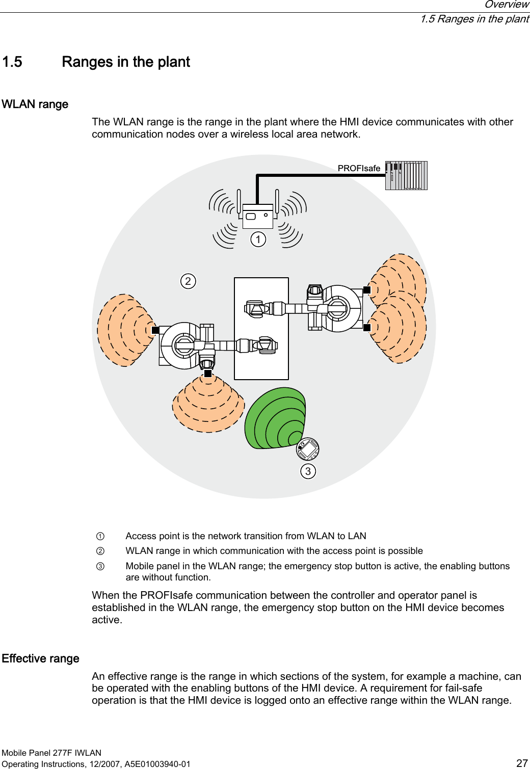
Siemens AG Mobile Panel 277 IWLAN Mobile Panel 277F IWLAN
UserManual.wiki
>
Siemens
>
277IWLAN-V100 User Manual
>
UserMan1
Contents
1.
UserMan1
2.
UserMan2
3.
UserMan Statement
4.
UserMan Statements
UserMan1
Navigation menu
Upload a User Manual
Namespaces
Wiki Guide
HTML
PDF
Info
Views
User Manual
Discussion / Help
Navigation
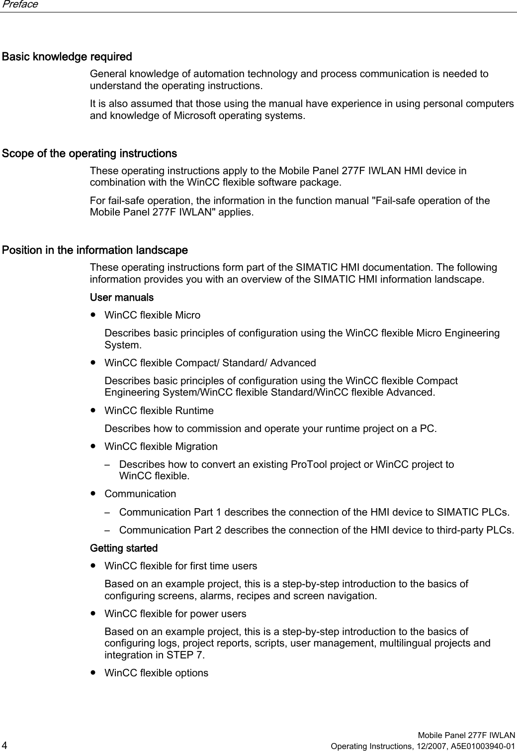
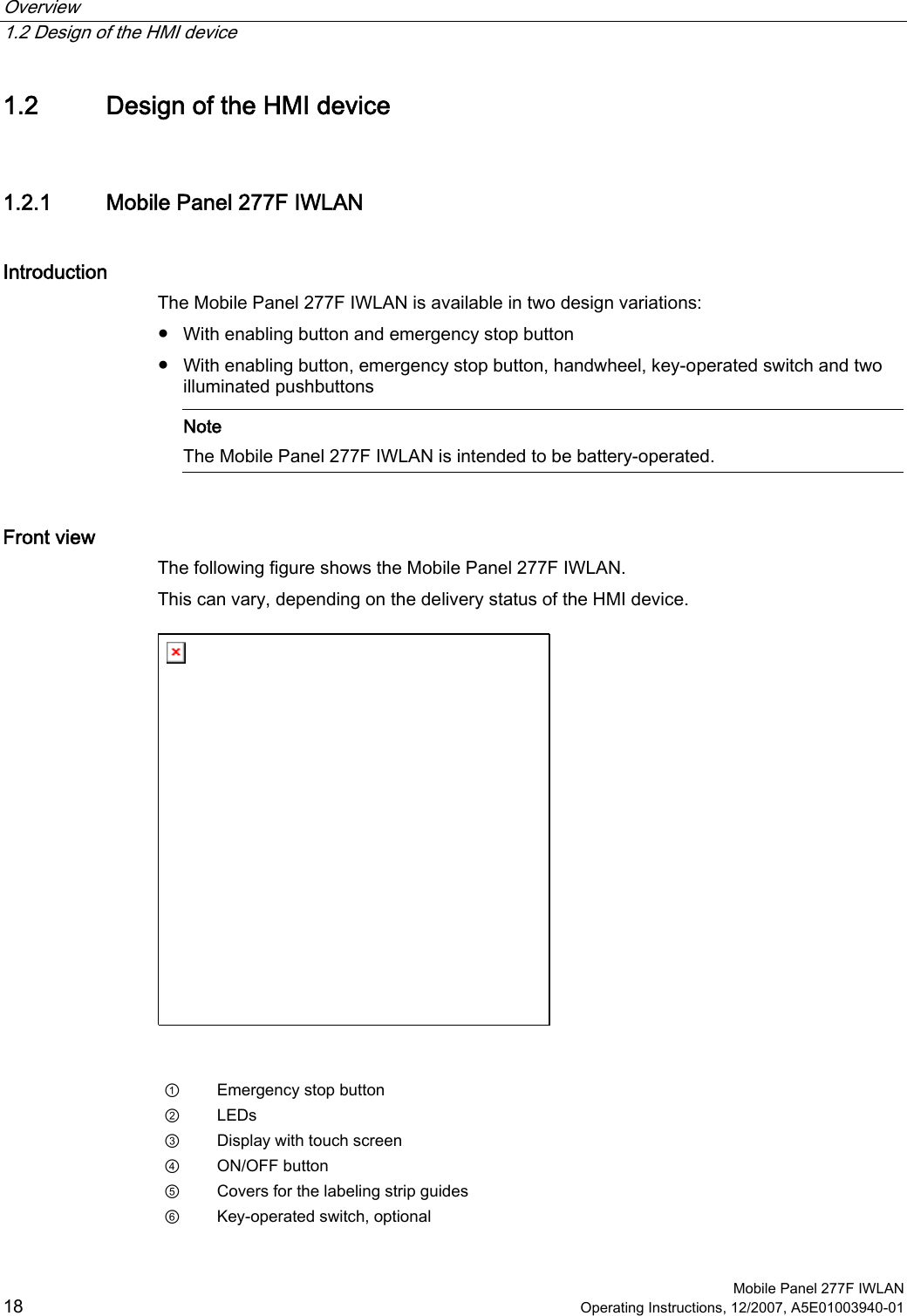
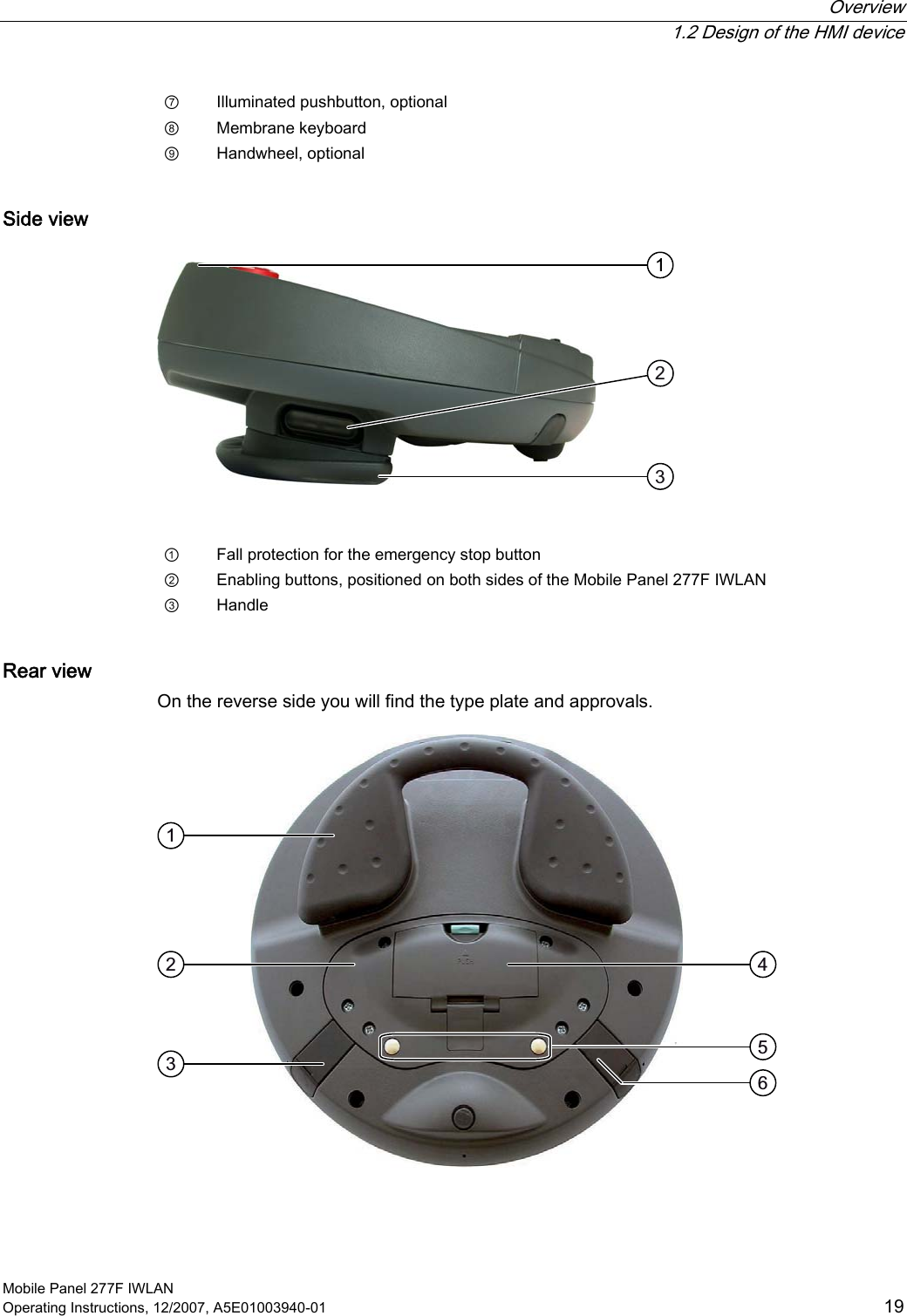
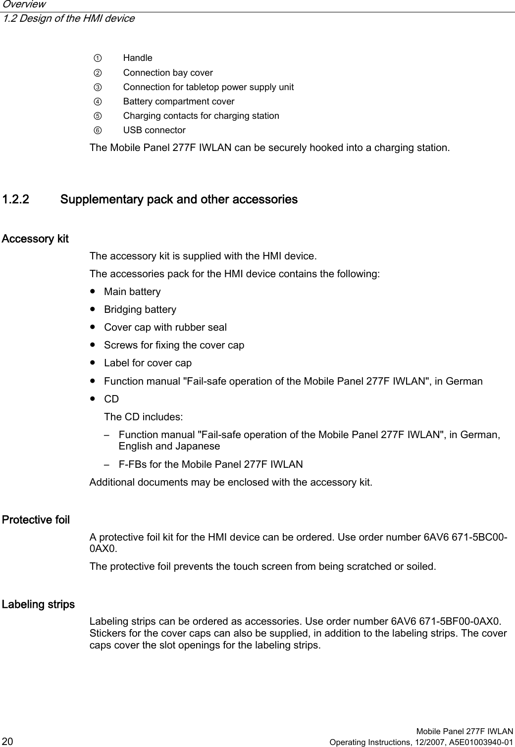
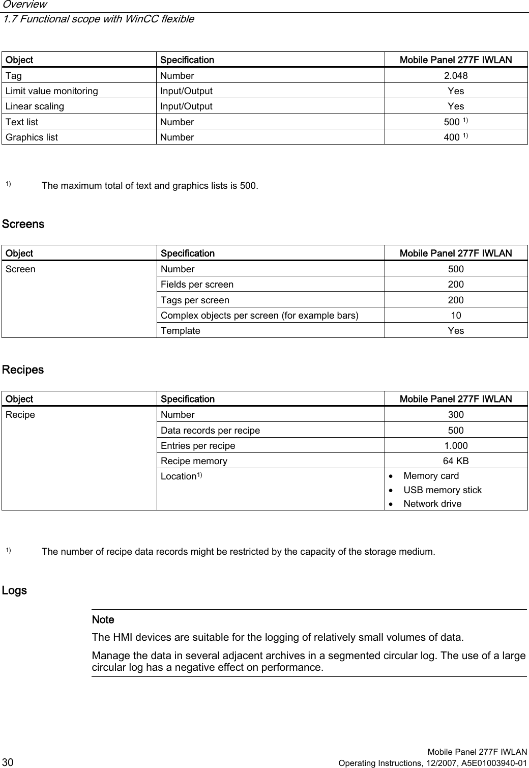
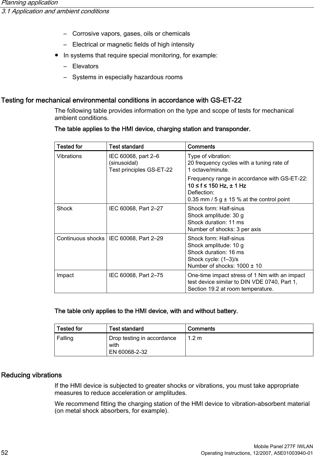
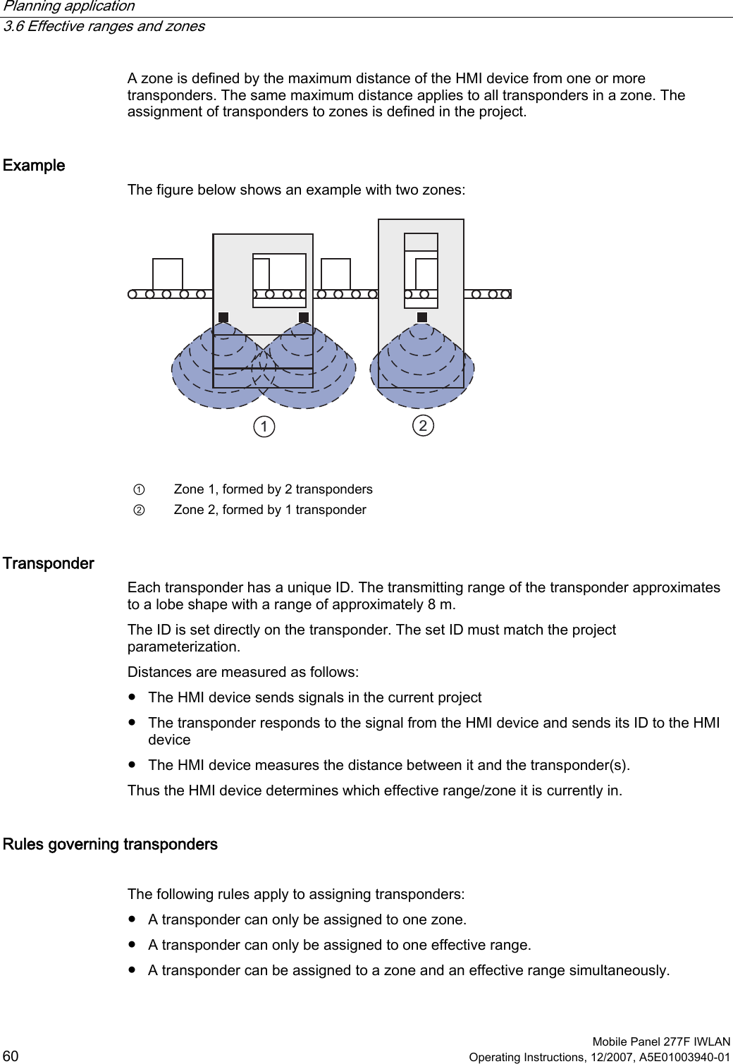
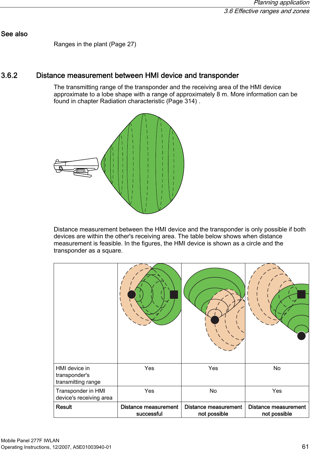
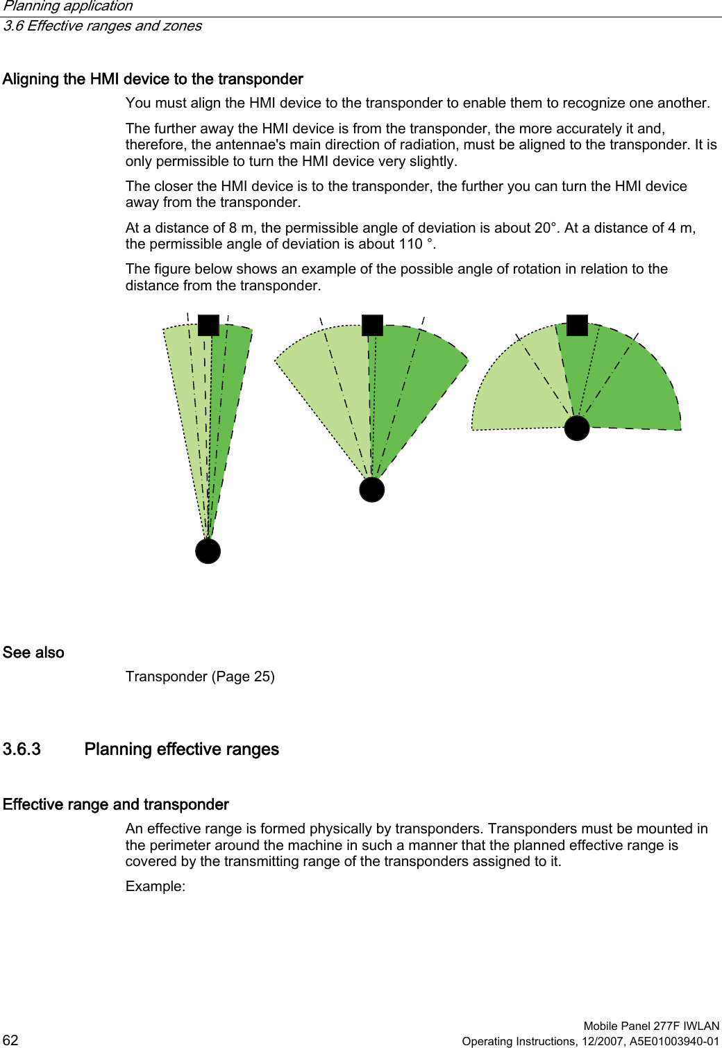
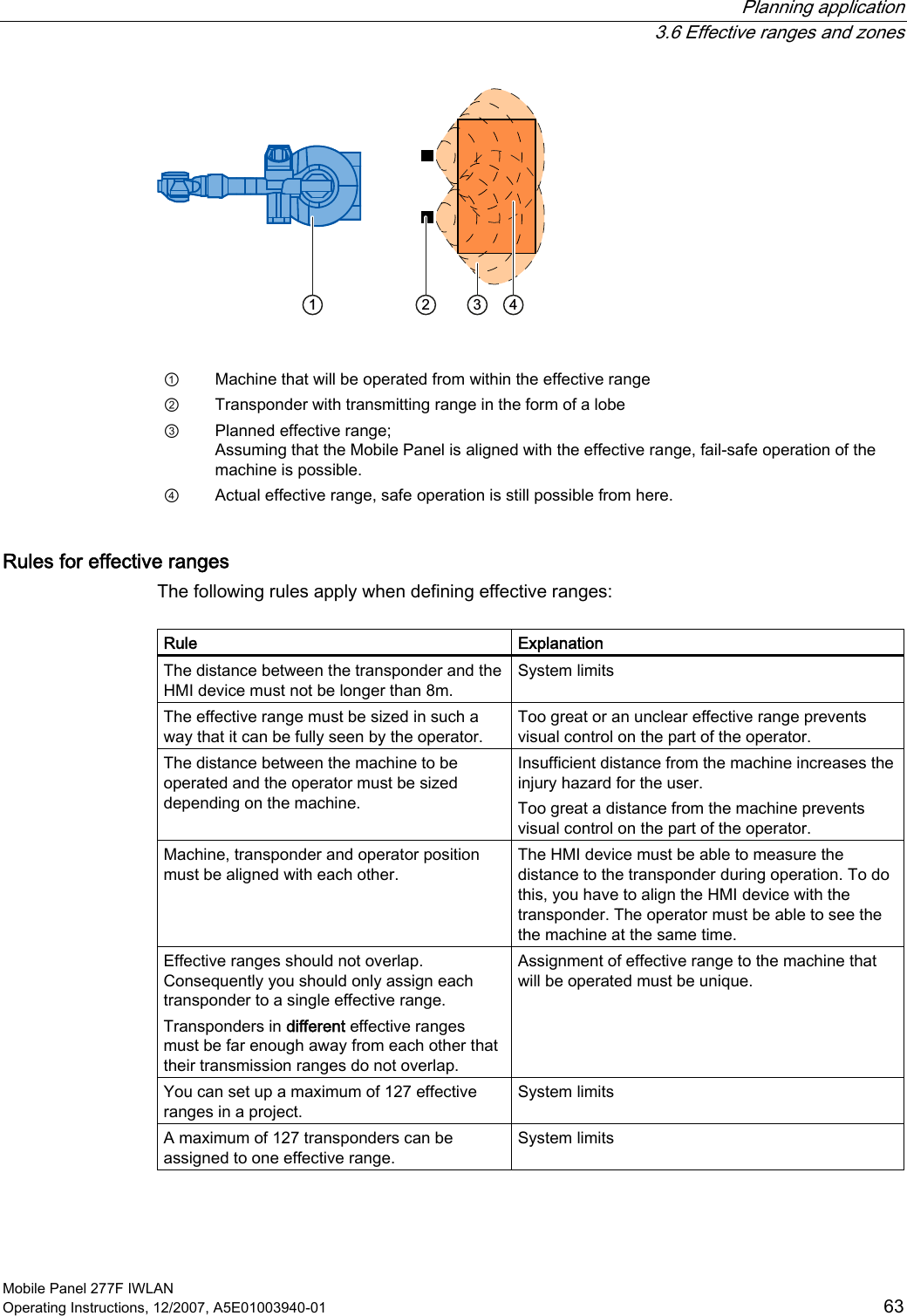
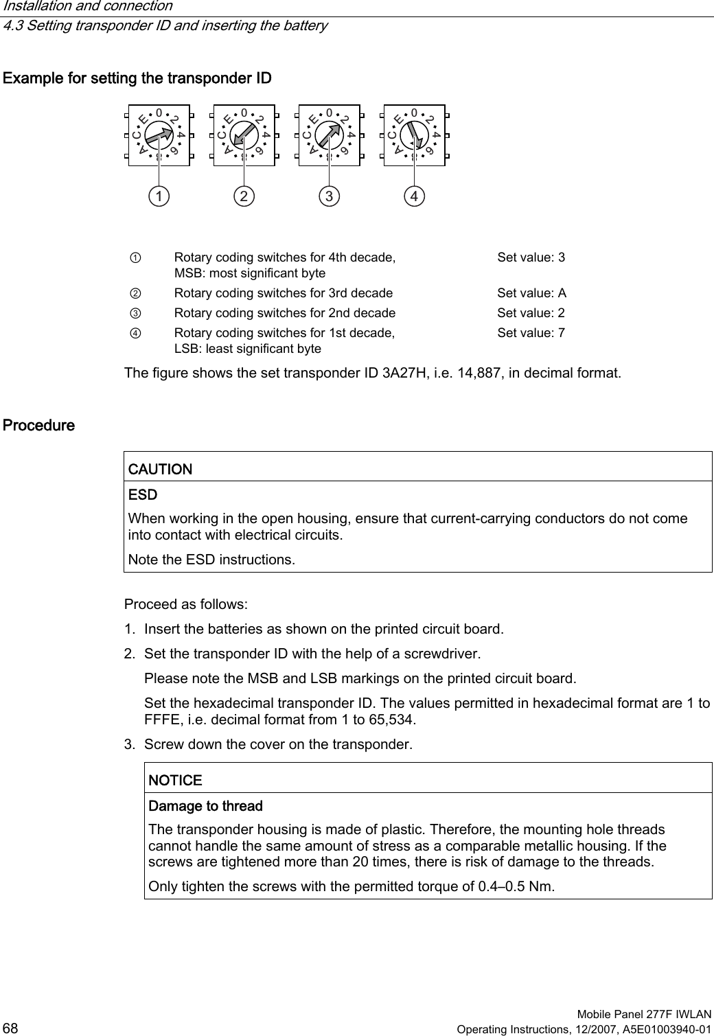

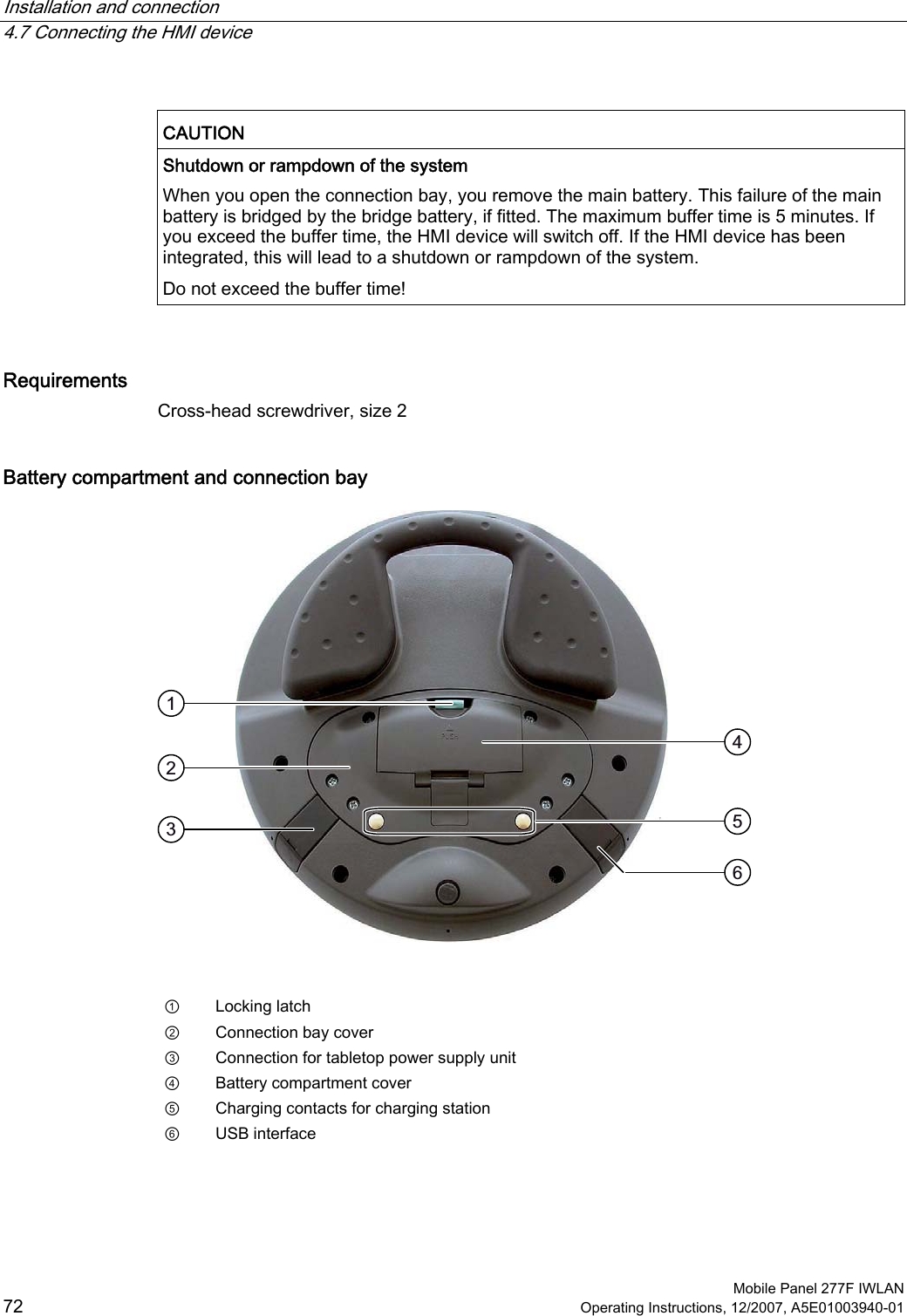
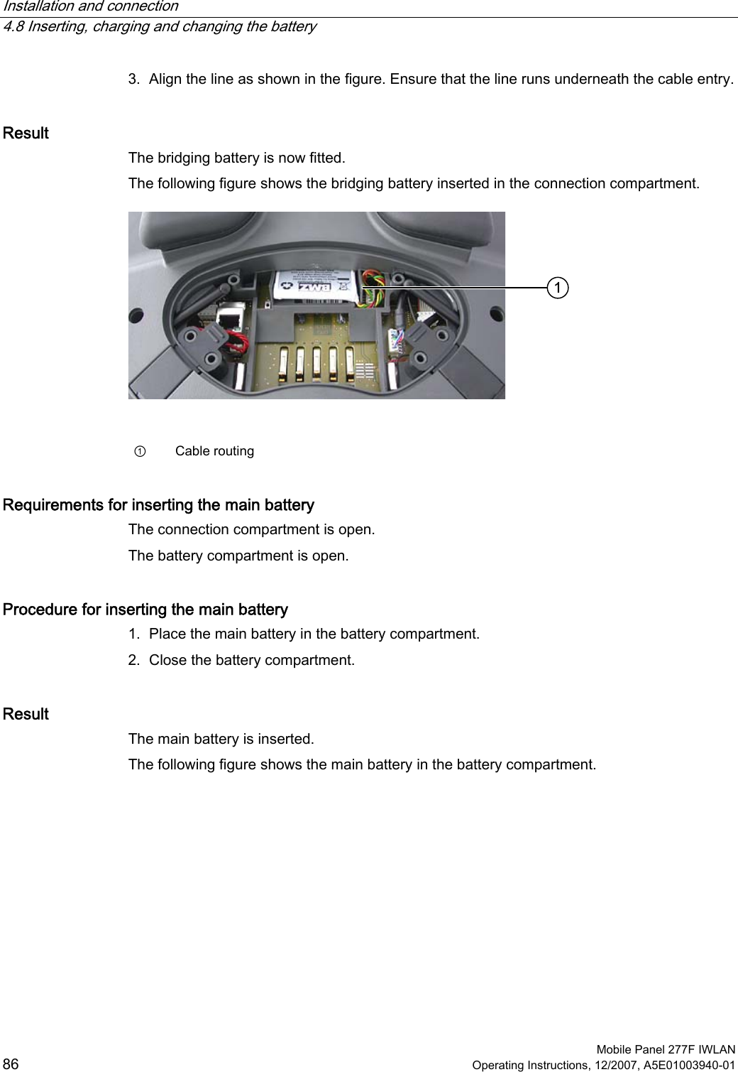
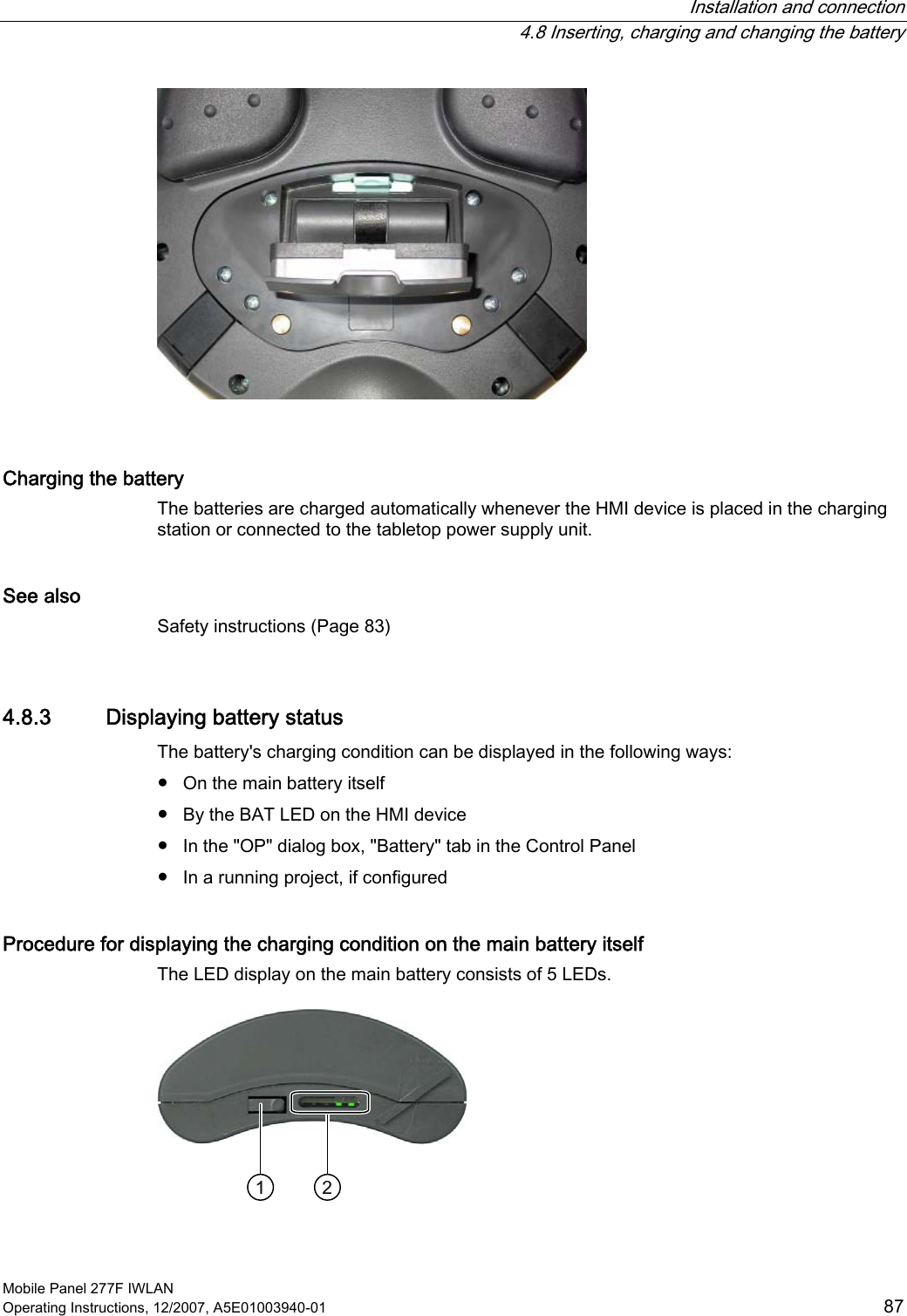
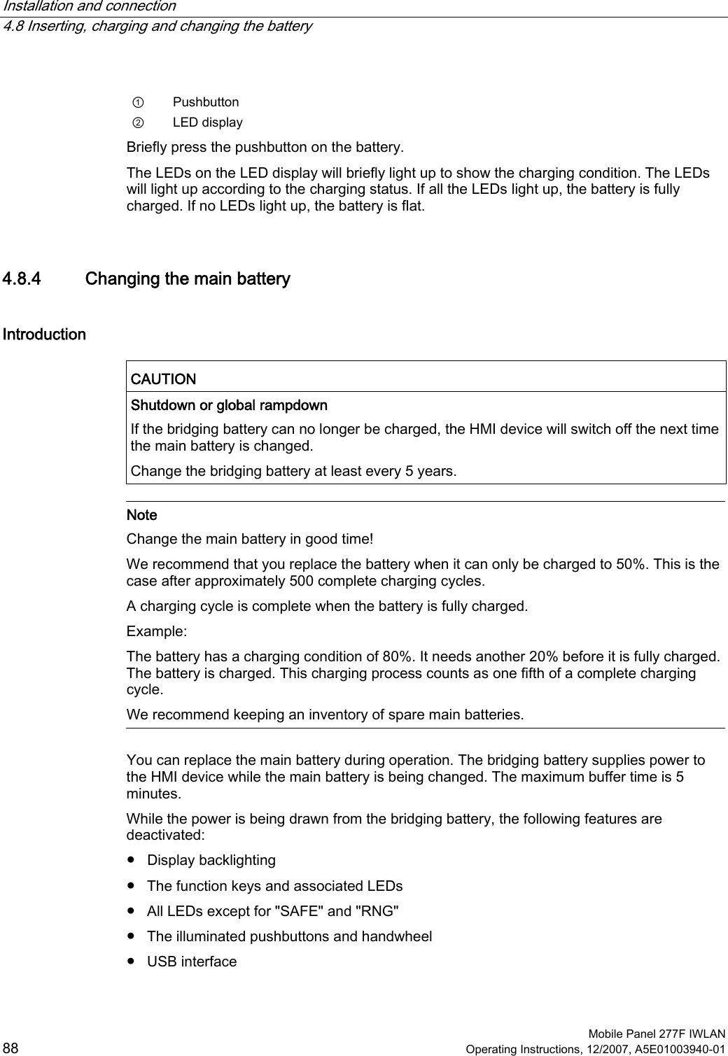
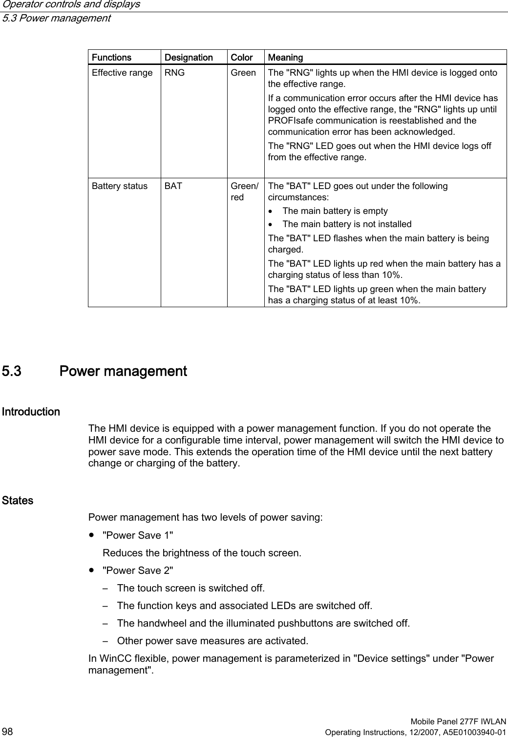
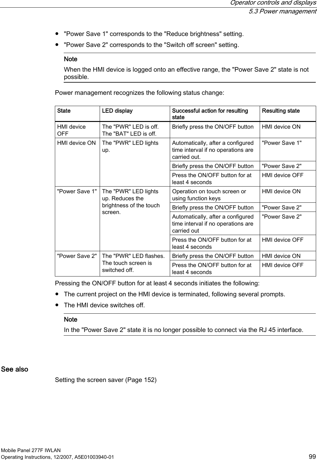
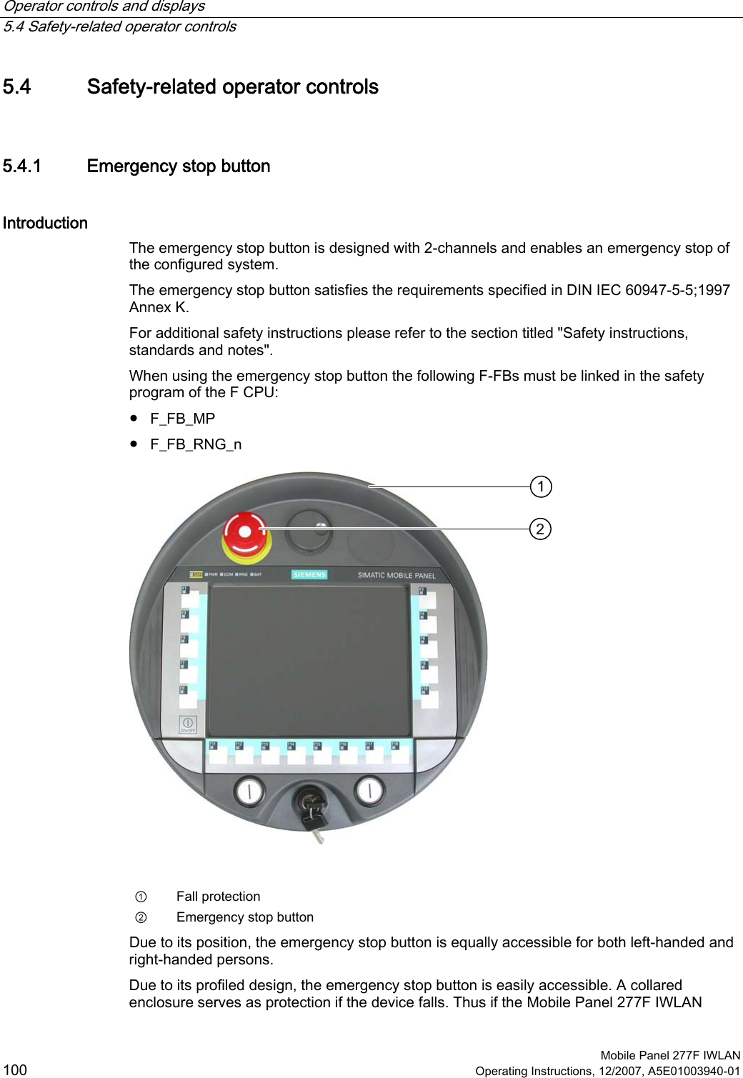
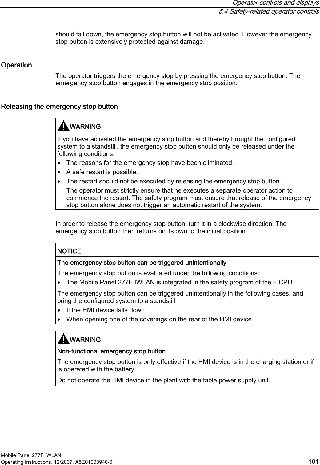
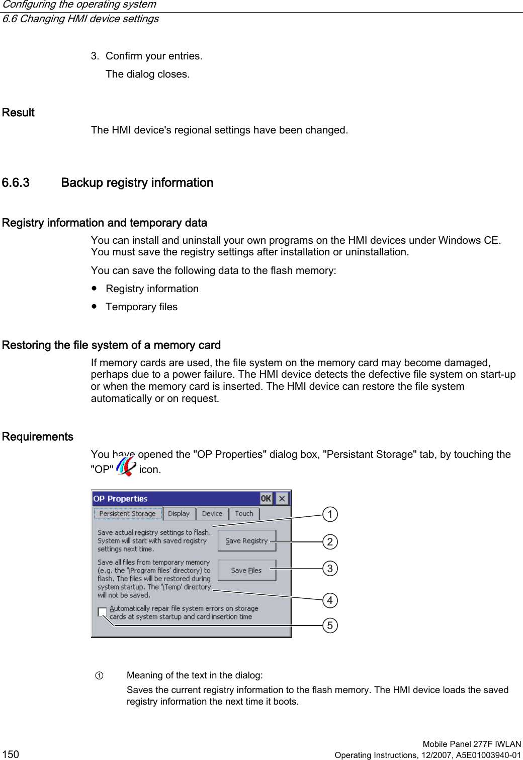
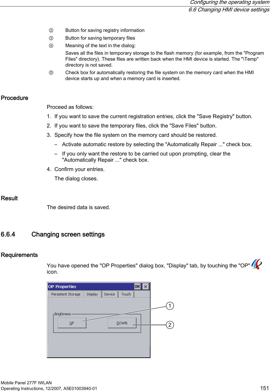
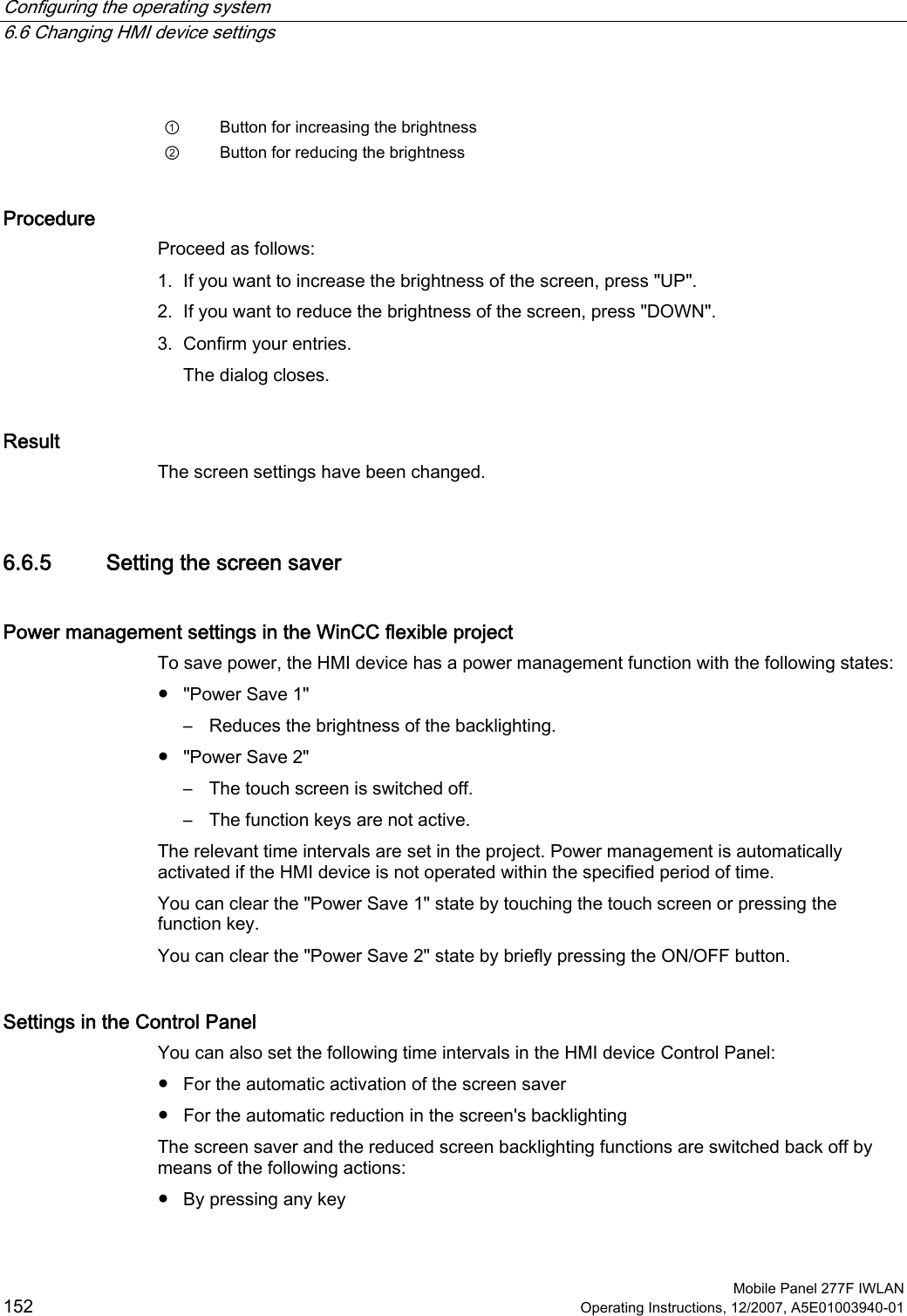
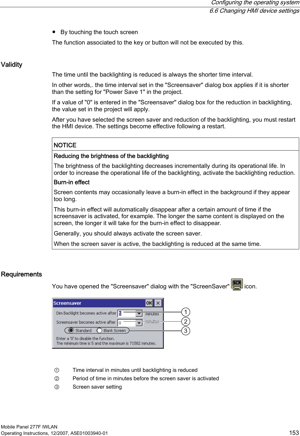
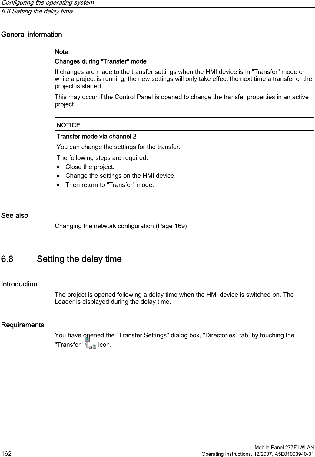
![Configuring the operating system 6.8 Setting the delay time Mobile Panel 277F IWLAN Operating Instructions, 12/2007, A5E01003940-01 163 ① Directory where the project file is saved ② Directory where the compressed source file of your project is saved The external memory card or the network connection can be defined as the storage location. During the next backup process, the project's source file is stored in the specified location. ③ Memory location and start file of the HMI device for the executable project file ④ Delay time selection box NOTICE Settings under "Project File" and "Path" Do not change the setting in the "Project File" and "Path:" boxes. The project may not open at the next start of the HMI device if changes are made here. Procedure for setting the delay time 1. Select the desired delay time in seconds from the "Wait [sec]:" selection box. With the value "0", the project starts immediately. It is now no longer possible to call the Loader after switching on the HMI device. If you still do need to access the Loader an operating element must be configured to close the project. 2. Confirm your entries. The dialog closes. Result The delay time for the HMI device is now set.](https://usermanual.wiki/Siemens/277IWLAN-V100.UserMan1/User-Guide-1034533-Page-163.png)