Siemens 277IWLAN-V100 Mobile Panel 277 IWLAN User Manual Mobile Panel 277F IWLAN
Siemens AG Mobile Panel 277 IWLAN Mobile Panel 277F IWLAN
Siemens >
Contents
UserMan1

Preface
Overview
1
Safety instructions,
standards and notes
2
Planning application
3
Installation and connection
4
Operator controls and
displays
5
Configuring the operating
system
6
Commissioning the HMI
device
7
Fail-safe mode
8
Operating a project
9
Operating alarms
10
Operating recipes
11
Maintenance and care
12
Technical specifications
13
Appendix
B
Abbreviations
C
SIMATIC HMI
HMI device
Mobile Panel 277F IWLAN
Operating Instructions
12/2007
A5E01003940-01
Order No.: 6AV6691-1DQ01-2AA0
Safety Guidelines
This manual contains notices you have to observe in order to ensure your personal safety, as well as to prevent
damage to property. The notices referring to your personal safety are highlighted in the manual by a safety alert
symbol, notices referring only to property damage have no safety alert symbol. These notices shown below are
graded according to the degree of danger.
DANGER
indicates that death or severe personal injury will result if proper precautions are not taken.
WARNING
indicates that death or severe personal injury may result if proper precautions are not taken.
CAUTION
with a safety alert symbol, indicates that minor personal injury can result if proper precautions are not taken.
CAUTION
without a safety alert symbol, indicates that property damage can result if proper precautions are not taken.
NOTICE
indicates that an unintended result or situation can occur if the corresponding information is not taken into
account.
If more than one degree of danger is present, the warning notice representing the highest degree of danger will
be used. A notice warning of injury to persons with a safety alert symbol may also include a warning relating to
property damage.
Qualified Personnel
The device/system may only be set up and used in conjunction with this documentation. Commissioning and
operation of a device/system may only be performed by qualified personnel. Within the context of the safety notes
in this documentation qualified persons are defined as persons who are authorized to commission, ground and
label devices, systems and circuits in accordance with established safety practices and standards.
Prescribed Usage
Note the following:
WARNING
This device may only be used for the applications described in the catalog or the technical description and only
in connection with devices or components from other manufacturers which have been approved or
recommended by Siemens. Correct, reliable operation of the product requires proper transport, storage,
positioning and assembly as well as careful operation and maintenance.
Trademarks
All names identified by ® are registered trademarks of the Siemens AG. The remaining trademarks in this
publication may be trademarks whose use by third parties for their own purposes could violate the rights of the
owner.
Disclaimer of Liability
We have reviewed the contents of this publication to ensure consistency with the hardware and software
described. Since variance cannot be precluded entirely, we cannot guarantee full consistency. However, the
information in this publication is reviewed regularly and any necessary corrections are included in subsequent
editions.
Siemens AG
Automation and Drives
Postfach 48 48
90327 NÜRNBERG
GERMANY
Ordernumber: A5E01003940-01
Ⓟ 01/2008
Copyright © Siemens AG 2007.
Technical data subject to change
Mobile Panel 277F IWLAN
Operating Instructions, 12/2007, A5E01003940-01 3
Preface
Purpose of the operating instructions
These operating instructions provide information based on the requirements defined by DIN
EN 62079 for mechanical engineering documentation. This information relates to the place of
use, transport, storage, mounting, use and maintenance.
These operating instructions are intended for the following user groups:
● Operators
The operator operates and monitors the system during the process control phase. The
following chapters are relevant to the operator:
– Operator controls and displays
– Fail-safe operation
– Operating a project
– Operating recipes
– Operating alarms
● Commissioning engineers
The commissioning engineer integrates the HMI device into the system and ensures the
operating capability of the HMI device for the process control phase.
All the operating instructions are relevant for the commissioning engineer.
Depending on the use of the HMI device, certain chapters may not be of relevance to the
commissioning engineer, for example the chapter "Maintenance and servicing".
● Service technicians
Service technicians rectify faults that occur during the process control phase.
The entire set of operating instructions is relevant to service technicians in principle.
Depending on the use of the HMI device, however, certain chapters may not be relevant
to them, for example the chapter on "Maintenance and care".
● Maintenance technicians
Maintenance technicians carry out regular maintenance work during the process control
phase. The chapter on "Maintenance and care" is relevant to maintenance technicians.
The chapter "Safety instructions, standards and information" should be particularly heeded
by all person groups.
The help integrated in WinCC flexible, the WinCC flexible Information System, contains
detailed information. The information system contains instructions, examples and reference
information in electronic form.

Preface
Mobile Panel 277F IWLAN
4 Operating Instructions, 12/2007, A5E01003940-01
Basic knowledge required
General knowledge of automation technology and process communication is needed to
understand the operating instructions.
It is also assumed that those using the manual have experience in using personal computers
and knowledge of Microsoft operating systems.
Scope of the operating instructions
These operating instructions apply to the Mobile Panel 277F IWLAN HMI device in
combination with the WinCC flexible software package.
For fail-safe operation, the information in the function manual "Fail-safe operation of the
Mobile Panel 277F IWLAN" applies.
Position in the information landscape
These operating instructions form part of the SIMATIC HMI documentation. The following
information provides you with an overview of the SIMATIC HMI information landscape.
User manuals
● WinCC flexible Micro
Describes basic principles of configuration using the WinCC flexible Micro Engineering
System.
● WinCC flexible Compact/ Standard/ Advanced
Describes basic principles of configuration using the WinCC flexible Compact
Engineering System/WinCC flexible Standard/WinCC flexible Advanced.
● WinCC flexible Runtime
Describes how to commission and operate your runtime project on a PC.
● WinCC flexible Migration
– Describes how to convert an existing ProTool project or WinCC project to
WinCC flexible.
● Communication
– Communication Part 1 describes the connection of the HMI device to SIMATIC PLCs.
– Communication Part 2 describes the connection of the HMI device to third-party PLCs.
Getting started
● WinCC flexible for first time users
Based on an example project, this is a step-by-step introduction to the basics of
configuring screens, alarms, recipes and screen navigation.
● WinCC flexible for power users
Based on an example project, this is a step-by-step introduction to the basics of
configuring logs, project reports, scripts, user management, multilingual projects and
integration in STEP 7.
● WinCC flexible options

Preface
Mobile Panel 277F IWLAN
Operating Instructions, 12/2007, A5E01003940-01 5
Based on an example project, this is a step-by-step introduction to the basics of
configuring the WinCC flexible Sm@rtServices, Sm@rtAccess and OPC server options.
● Mobile Panel 277 IWLAN
Introduces project design for WLAN communication step by step using a sample
structure.
Operating instructions
● Operating instructions for SIMATIC HMI devices
– OP 73, OP 77A, OP 77B
– TP 170micro, TP 170A, TP 170B, OP 170B
– OP 73micro, TP 177micro
– TP 177A, TP 177B, OP 177B
– TP 270, OP 270
– TP 277, OP 277
– MP 270B
– MP 277
– MP 370
– MP 377
● Operating instructions for mobile SIMATIC HMI devices
– Mobile Panel 177
– Mobile Panel 277
– Mobile Panel 277 IWLAN
– Mobile Panel 277F IWLAN
● Operating instructions (compact) for SIMATIC HMI devices
– OP 77B
– Mobile Panel 177
– Mobile Panel 277
● Operating instructions for SIMATIC accessories
– Industrial USB Hub 4
● Function manual
– Fail-safe operation of the Mobile Panel 277F IWLAN
Online availability
Technical documentation on SIMATIC products and SIMATIC systems is available in PDF
format in various languages at the following addresses:
● SIMATIC Guide Technical Documentation in German:
"http://www.ad.siemens.de/simatic/portal/html_00/techdoku.htm"
● SIMATIC Guide for Technical Documentation in English:
"http://www.ad.siemens.de/simatic/portal/html_76/techdoku.htm"

Preface
Mobile Panel 277F IWLAN
6 Operating Instructions, 12/2007, A5E01003940-01
Photos
The HMI device is sometimes shown in the form of photographs in these operating
instructions. The photographs of the HMI device may differ slightly from the factory state of
the HMI device.
Conventions
Configuration and runtime software differ with regard to their names as follows:
● "WinCC flexible 2007" for example, refers to the configuration software
The term "WinCC flexible" is used in a general context. The full name, for example
"WinCC flexible 2007", is always used when it is necessary to differentiate between
different versions of the configuration software.
● "WinCC flexible Runtime" refers to the runtime software that can run on HMI devices
The name "Mobile Panel 277 Wireless" is the collective term for the following HMI devices:
● Mobile Panel 277 IWLAN
● Mobile Panel 277F IWLAN
The following text notation will facilitate reading these operating instructions:
Notation Scope
"Add screen" • Terminology that appears in the user interface, for example
dialog names, tabs, buttons, menu entries
• Inputs required, for example limit values, tag values
• Path information
"File > Edit" Operational sequences, for example, menu commands, context
menu commands
<F1>, <Alt+P> Keyboard operation
Please observe notes labeled as follows:
Note
Notes contain important information concerning the product, its use or a specific section of
the documentation to which you should pay particular attention.
Registered trademarks
Names labeled with a ® symbol are registered trademarks of the Siemens AG. Other names
used in this documentation may be trademarks, the use of which by third parties for their
own purposes could violate the rights of the owner.
● HMI®
● SIMATIC®
● SIMATIC HMI®
● SIMATIC ProTool®
● WinCC®

Preface
Mobile Panel 277F IWLAN
Operating Instructions, 12/2007, A5E01003940-01 7
Representatives and offices
If you have any further questions relating to the products described in this manual, please
contact your local representative at the Siemens branch nearest you.
Your Siemens representative can be found at "http://www.siemens.com/automation/partner".
Training center
Siemens AG offers a variety of training courses to familiarize you with automation systems.
Please contact your regional training center, or our central training center in 90327
Nuremberg, Germany, for details.
Phone: +49 (911) 895-3200
Internet: "http://www.sitrain.com"
Technical support
You can find technical support for all A&D projects
● Using the support request form on the web at:
"http://www.siemens.de/automation/support-request"
● Phone: + 49 180 5050 222
● Fax: + 49 180 5050 223
Further information about our technical support is available on the Internet at
"http://www.siemens.com/automation/service".
Service & Support on the Internet
Service & Support provides additional comprehensive information on SIMATIC products
through online services at "http://www.siemens.com/automation/support":
● Newsletters with the latest information about your products
● A large document base is available using our Service & Support search engine
● A forum for global exchange of information by users and experts
● Current product information, FAQs and downloads
● Your local Automation & Drives representative
● Information about field service, repairs, spare parts and much more under the heading
"Services"
Recycling and disposal
Due to the low levels of pollutants in the HMI devices described in these operating
instructions, they can be recycled. For environment-friendly recycling and disposal of your
old equipment, contact a certified disposal facility for electronic scrap.
Mobile Panel 277F IWLAN
Operating Instructions, 12/2007, A5E01003940-01 9
Table of contents
Preface ...................................................................................................................................................... 3
1 Overview.................................................................................................................................................. 17
1.1 Product overview .........................................................................................................................17
1.2 Design of the HMI device.............................................................................................................18
1.2.1 Mobile Panel 277F IWLAN...........................................................................................................18
1.2.2 Supplementary pack and other accessories................................................................................20
1.2.3 Battery..........................................................................................................................................22
1.2.4 Charging station...........................................................................................................................22
1.3 Configuration and process control phase ....................................................................................24
1.4 Transponder.................................................................................................................................25
1.5 Ranges in the plant ......................................................................................................................27
1.6 Fail-safe operation .......................................................................................................................28
1.7 Functional scope with WinCC flexible..........................................................................................29
1.8 Software options ..........................................................................................................................32
1.9 Communication ............................................................................................................................32
2 Safety instructions, standards and notes ................................................................................................. 35
2.1 Safety instructions........................................................................................................................35
2.2 Standards, certificates and approvals..........................................................................................37
2.3 Operating safety...........................................................................................................................39
2.4 Power supply................................................................................................................................40
2.5 Notes about usage.......................................................................................................................42
2.6 Risk analysis ................................................................................................................................43
2.7 Safety functions of the emergency stop button............................................................................43
2.8 Enabling button ............................................................................................................................44
2.9 Electromagnetic compatibility ......................................................................................................46
2.10 Transport and storage conditions ................................................................................................48
3 Planning application................................................................................................................................. 51
3.1 Application and ambient conditions .............................................................................................51
3.2 Mounting location and clearance of charging station ..................................................................54
3.3 Information on insulation tests, protection class and degree of protection..................................56
3.4 Rated voltages .............................................................................................................................57
3.5 Required properties of the WLAN connection .............................................................................57
3.6 Effective ranges and zones..........................................................................................................58

Table of contents
Mobile Panel 277F IWLAN
10 Operating Instructions, 12/2007, A5E01003940-01
3.6.1 Division of the system into effective ranges and zones .............................................................. 58
3.6.2 Distance measurement between HMI device and transponder.................................................. 61
3.6.3 Planning effective ranges............................................................................................................ 62
4 Installation and connection ...................................................................................................................... 65
4.1 Checking the package contents..................................................................................................65
4.2 Mounting the charging station..................................................................................................... 66
4.3 Setting transponder ID and inserting the battery ........................................................................ 66
4.4 Mounting the transponder ........................................................................................................... 69
4.5 Electrical installation.................................................................................................................... 69
4.6 Connection of the charging station to the power supply ............................................................. 70
4.7 Connecting the HMI device......................................................................................................... 71
4.7.1 Opening and closing the terminal compartment ......................................................................... 71
4.7.2 Interfaces of the HMI device ....................................................................................................... 76
4.7.3 Connecting the configuring PC ................................................................................................... 77
4.7.4 Connecting the PLC.................................................................................................................... 79
4.7.5 Connecting the printer................................................................................................................. 80
4.7.6 Connecting USB devices ............................................................................................................ 81
4.7.7 Connecting the tabletop power supply unit................................................................................. 82
4.8 Inserting, charging and changing the battery.............................................................................. 83
4.8.1 Safety instructions....................................................................................................................... 83
4.8.2 Inserting batteries for the first time.............................................................................................. 85
4.8.3 Displaying battery status............................................................................................................. 87
4.8.4 Changing the main battery.......................................................................................................... 88
4.8.5 Changing the bridging battery..................................................................................................... 89
4.9 Switching on and testing the HMI device.................................................................................... 91
5 Operator controls and displays ................................................................................................................ 95
5.1 Overview ..................................................................................................................................... 95
5.2 Displays on the Mobile Panel 277F IWLAN................................................................................ 96
5.3 Power management.................................................................................................................... 98
5.4 Safety-related operator controls................................................................................................ 100
5.4.1 Emergency stop button ............................................................................................................. 100
5.4.2 Enabling button ......................................................................................................................... 102
5.5 Operator controls ...................................................................................................................... 104
5.5.1 Handwheel ................................................................................................................................ 104
5.5.2 Key-operated switch.................................................................................................................. 105
5.5.3 Illuminated pushbutton.............................................................................................................. 106
5.5.4 Evaluation of the operator controls ........................................................................................... 107
5.5.4.1 Overview ................................................................................................................................... 107
5.5.4.2 Evaluating operator controls as direct keys .............................................................................. 107
5.5.4.3 Activation of function key LEDs using system functions........................................................... 110
5.5.4.4 Evaluation of the handwheel with system functions ................................................................. 111
5.5.4.5 Evaluation of the key-operated switch with system functions................................................... 112
5.5.4.6 Evaluation and activation of the illuminated pushbuttons ......................................................... 112
5.6 Using a memory card with the HMI device ............................................................................... 113
5.7 Labeling the function keys......................................................................................................... 116

Table of contents
Mobile Panel 277F IWLAN
Operating Instructions, 12/2007, A5E01003940-01 11
5.8 Holding the mobile panel and fixing it to the wall.......................................................................118
5.9 Charging station.........................................................................................................................120
5.9.1 Charging batteries in the charging compartment.......................................................................120
5.9.2 Displays on the charging station................................................................................................122
5.9.3 Locking the charging station ......................................................................................................123
6 Configuring the operating system .......................................................................................................... 125
6.1 Loader........................................................................................................................................125
6.2 WLAN.........................................................................................................................................128
6.2.1 Overview ....................................................................................................................................128
6.2.2 Parameterizing the WLAN connection.......................................................................................131
6.3 Control Panel .............................................................................................................................135
6.3.1 Overview ....................................................................................................................................135
6.3.2 Reference...................................................................................................................................136
6.3.3 Operating the Control Panel ......................................................................................................137
6.4 Changing settings for operation.................................................................................................140
6.4.1 Configuring the screen keyboard...............................................................................................140
6.4.2 Setting the character repeat rate of the screen keyboard .........................................................141
6.4.3 Setting the double-click..............................................................................................................143
6.4.4 Calibrating the touch screen ......................................................................................................144
6.5 Changing password protection ..................................................................................................146
6.6 Changing HMI device settings ...................................................................................................147
6.6.1 Setting the date and time...........................................................................................................147
6.6.2 Changing regional settings ........................................................................................................149
6.6.3 Backup registry information .......................................................................................................150
6.6.4 Changing screen settings ..........................................................................................................151
6.6.5 Setting the screen saver ............................................................................................................152
6.6.6 Changing the printer properties .................................................................................................154
6.6.7 Restarting the HMI device..........................................................................................................156
6.6.8 Displaying information about the HMI device ............................................................................157
6.6.9 Displaying system properties.....................................................................................................158
6.6.10 Activating vibration alarm...........................................................................................................159
6.7 Programming the data channel..................................................................................................160
6.8 Setting the delay time ................................................................................................................162
6.9 Setting the PROFIsafe address .................................................................................................164
6.10 Enabling PROFINET IO.............................................................................................................165
6.11 Configuring network operation...................................................................................................167
6.11.1 Overview of network operation ..................................................................................................167
6.11.2 Setting the device name of the HMI device ...............................................................................168
6.11.3 Changing the network configuration ..........................................................................................169
6.11.4 Changing the logon data............................................................................................................171
6.11.5 Changing e-mail settings ...........................................................................................................172
6.12 Changing internet settings .........................................................................................................173
6.12.1 Changing internet settings .........................................................................................................173
6.12.2 Setting the proxy server .............................................................................................................174
6.12.3 Changing data protection settings .............................................................................................175
6.12.4 Importing and deleting certificates .............................................................................................176
6.13 Backing up and restoring with an external memory medium ....................................................177

Table of contents
Mobile Panel 277F IWLAN
12 Operating Instructions, 12/2007, A5E01003940-01
6.14 Displaying battery status........................................................................................................... 181
6.15 Activate memory management ................................................................................................. 182
7 Commissioning the HMI device ............................................................................................................. 185
7.1 Overview ................................................................................................................................... 185
7.2 Operating modes....................................................................................................................... 186
7.3 Using existing projects .............................................................................................................. 187
7.4 Data transmission options......................................................................................................... 188
7.5 Preparing and backing up a project .......................................................................................... 189
7.5.1 Overview ................................................................................................................................... 189
7.5.2 Transfer..................................................................................................................................... 190
7.5.2.1 Overview ................................................................................................................................... 190
7.5.2.2 Starting manual transfer............................................................................................................ 190
7.5.2.3 Starting automatic transfer........................................................................................................ 191
7.5.2.4 Starting backtransfer ................................................................................................................. 193
7.5.3 Testing a project........................................................................................................................ 194
7.5.4 Acceptance of the system......................................................................................................... 196
7.5.4.1 Overview ................................................................................................................................... 196
7.5.4.2 Accepting effective ranges and transponders........................................................................... 196
7.5.4.3 Testing effective ranges............................................................................................................ 199
7.5.5 Testing zones............................................................................................................................ 200
7.5.6 Backup and restore ................................................................................................................... 200
7.5.6.1 Overview ................................................................................................................................... 200
7.5.6.2 Backup and restore using WinCC flexible................................................................................. 201
7.5.6.3 Backup and restore using ProSave .......................................................................................... 203
7.5.7 Updating the operating system ................................................................................................. 204
7.5.7.1 Overview ................................................................................................................................... 204
7.5.7.2 Updating the operating system using WinCC flexible............................................................... 206
7.5.7.3 Updating the operating system using ProSave......................................................................... 207
7.5.7.4 Resetting to factory settings with WinCC flexible...................................................................... 208
7.5.7.5 Resetting to factory settings with ProSave ............................................................................... 210
7.5.8 Installing and removing options ................................................................................................212
7.5.8.1 Overview ................................................................................................................................... 212
7.5.8.2 Installing and removing options using WinCC flexible .............................................................. 212
7.5.8.3 Installing and removing options using ProSave........................................................................ 214
7.5.9 Transferring and transferring back license keys ....................................................................... 215
7.5.9.1 Overview ................................................................................................................................... 215
7.5.9.2 Transferring and transferring back license keys ....................................................................... 216
8 Fail-safe mode....................................................................................................................................... 219
8.1 Organizational measures .......................................................................................................... 219
8.2 Switch-off behavior.................................................................................................................... 220
8.3 Integrating the HMI device ........................................................................................................ 222
8.4 Removing the HMI device......................................................................................................... 223
8.5 Logging onto and off from the effective range .......................................................................... 224
8.6 "Override" mode........................................................................................................................ 226
9 Operating a project ................................................................................................................................ 231
9.1 Starting the project .................................................................................................................... 231

Table of contents
Mobile Panel 277F IWLAN
Operating Instructions, 12/2007, A5E01003940-01 13
9.2 Error cases.................................................................................................................................232
9.3 Direct keys .................................................................................................................................234
9.4 Operator input options ...............................................................................................................235
9.5 Function keys.............................................................................................................................237
9.6 Setting the project language ......................................................................................................238
9.7 Input ...........................................................................................................................................239
9.7.1 Overview ....................................................................................................................................239
9.7.2 Entering and editing numerical values.......................................................................................240
9.7.3 Entering and editing alphanumerical values..............................................................................242
9.7.4 Entering the date and time.........................................................................................................243
9.7.5 Entering symbolic values ...........................................................................................................244
9.8 Displaying infotext......................................................................................................................244
9.9 Device-specific displays.............................................................................................................246
9.9.1 Displaying battery status............................................................................................................246
9.9.2 Displaying WLAN quality............................................................................................................246
9.9.3 Displaying the effective range name..........................................................................................247
9.9.4 Displaying the effective range quality ........................................................................................248
9.9.5 Displaying zone names..............................................................................................................249
9.9.6 Displaying zone quality ..............................................................................................................250
9.10 Bar and gauge ...........................................................................................................................251
9.11 Operating the slider control........................................................................................................252
9.12 Operating the switch ..................................................................................................................253
9.13 Operating the trend view............................................................................................................254
9.14 Operating the Status Force........................................................................................................256
9.14.1 Overview ....................................................................................................................................256
9.14.2 Operation ...................................................................................................................................258
9.15 Operating the Sm@rtClient view ...............................................................................................259
9.15.1 Overview ....................................................................................................................................259
9.15.2 Operation ...................................................................................................................................260
9.16 Project security ..........................................................................................................................261
9.16.1 Overview ....................................................................................................................................261
9.16.2 User view ...................................................................................................................................263
9.16.3 User logon..................................................................................................................................264
9.16.4 User logoff..................................................................................................................................266
9.16.5 Creating users............................................................................................................................266
9.16.6 Changing user data....................................................................................................................268
9.16.7 Deleting users ............................................................................................................................269
9.17 Closing the project .....................................................................................................................269
10 Operating alarms ................................................................................................................................... 271
10.1 Overview ....................................................................................................................................271
10.2 Recognizing pending alarms......................................................................................................272
10.3 Displaying alarms.......................................................................................................................273
10.4 Display infotexts for an alarm.....................................................................................................275
10.5 Acknowledge alarm....................................................................................................................275

Table of contents
Mobile Panel 277F IWLAN
14 Operating Instructions, 12/2007, A5E01003940-01
10.6 Edit alarm .................................................................................................................................. 276
11 Operating recipes .................................................................................................................................. 277
11.1 Overview ................................................................................................................................... 277
11.2 Structure of a recipe.................................................................................................................. 277
11.3 Recipes in the project................................................................................................................ 279
11.4 Recipe displays ......................................................................................................................... 280
11.5 Recipe values in the HMI device and the PLC.......................................................................... 283
11.6 Operating the recipe view ......................................................................................................... 284
11.6.1 Overview ................................................................................................................................... 284
11.6.2 Creating a recipe data record.................................................................................................... 285
11.6.3 Editing a recipe data record ...................................................................................................... 286
11.6.4 Deleting a recipe data record.................................................................................................... 287
11.6.5 Synchronizing tags.................................................................................................................... 288
11.6.6 Reading a recipe data record from the PLC ............................................................................. 289
11.6.7 Transferring a recipe data record to the PLC............................................................................ 290
11.7 Operating the simple recipe view.............................................................................................. 290
11.7.1 Overview ................................................................................................................................... 290
11.7.2 Creating a recipe data record.................................................................................................... 292
11.7.3 Editing a recipe data record ...................................................................................................... 293
11.7.4 Deleting a recipe data record.................................................................................................... 294
11.7.5 Reading a recipe data record from the PLC ............................................................................. 295
11.7.6 Transferring a recipe data record to the PLC............................................................................ 295
11.8 Exporting a recipe data record.................................................................................................. 296
11.9 Importing a recipe data record .................................................................................................. 297
11.10 Examples................................................................................................................................... 298
11.10.1 Entering a recipe data record.................................................................................................... 298
11.10.2 Manual production sequence.................................................................................................... 299
12 Maintenance and care ........................................................................................................................... 301
12.1 Maintenance and care............................................................................................................... 301
12.2 Spare parts and repairs............................................................................................................. 302
13 Technical specifications......................................................................................................................... 305
13.1 Dimension drawings.................................................................................................................. 305
13.1.1 Mobile Panel 277F IWLAN........................................................................................................305
13.1.2 Charging station ........................................................................................................................ 307
13.1.3 Transponder.............................................................................................................................. 308
13.2 Specifications ............................................................................................................................ 308
13.2.1 Mobile Panel 277F IWLAN........................................................................................................308
13.2.2 Batteries .................................................................................................................................... 311
13.2.3 Charging station ........................................................................................................................ 312
13.2.4 Transponder.............................................................................................................................. 312
13.2.5 Description of interfaces on the HMI device ............................................................................. 313
13.3 Radiation characteristic............................................................................................................. 314
13.3.1 Radiation characteristic of the transponder .............................................................................. 314
13.3.2 Radiation characteristic of HMI device...................................................................................... 316
B Appendix................................................................................................................................................ 321

Table of contents
Mobile Panel 277F IWLAN
Operating Instructions, 12/2007, A5E01003940-01 15
B.1 ESD guideline ............................................................................................................................321
B.2 System alarms ...........................................................................................................................323
C Abbreviations......................................................................................................................................... 325
C.1 Abbreviations .............................................................................................................................325
Glossary ................................................................................................................................................ 327
Index...................................................................................................................................................... 335
Mobile Panel 277F IWLAN
Operating Instructions, 12/2007, A5E01003940-01 17
Overview 1
1.1 Product overview
Expanded possible fields of application – with Mobile Panel 277F IWLAN
The Mobile Panel 277F IWLAN offers the option of implementing mobile safety functions
(emergency stop and enabling) at any point of a machine or system.
An effective range limit has been implemented for the Mobile Panel 277F IWLAN. Depending
on his or her location, the operator receives a secure, electronically monitored operator
control enable.
The HMI device communicates with the F-CPU via WLAN. This enables the operator to
operate different machines or systems without cables getting in the way.
The Mobile Panel 277F IWLAN is characterized by short commissioning times, a large user
memory and high performance, and is optimized for projects based on WinCC flexible.
The Mobile Panel 277F IWLAN has the following features:
● Safety-related operator controls:
– Emergency stop button
– Enabling button
● Effective range concept
● Wireless operation with
– IWLAN interface via PROFINET
– Battery operation
● 7.5" TFT screen with 64k colors
● 18 function keys with LED
● Extended HMI functions
Overview
1.2 Design of the HMI device
Mobile Panel 277F IWLAN
18 Operating Instructions, 12/2007, A5E01003940-01
1.2 Design of the HMI device
1.2.1 Mobile Panel 277F IWLAN
Introduction
The Mobile Panel 277F IWLAN is available in two design variations:
● With enabling button and emergency stop button
● With enabling button, emergency stop button, handwheel, key-operated switch and two
illuminated pushbuttons
Note
The Mobile Panel 277F IWLAN is intended to be battery-operated.
Front view
The following figure shows the Mobile Panel 277F IWLAN.
This can vary, depending on the delivery status of the HMI device.
① Emergency stop button
② LEDs
③ Display with touch screen
④ ON/OFF button
⑤ Covers for the labeling strip guides
⑥ Key-operated switch, optional
Overview
1.2 Design of the HMI device
Mobile Panel 277F IWLAN
Operating Instructions, 12/2007, A5E01003940-01 19
⑦ Illuminated pushbutton, optional
⑧ Membrane keyboard
⑨ Handwheel, optional
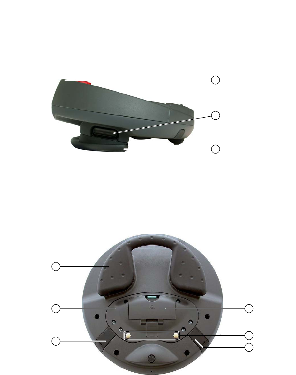
Side view
① Fall protection for the emergency stop button
② Enabling buttons, positioned on both sides of the Mobile Panel 277F IWLAN
③ Handle
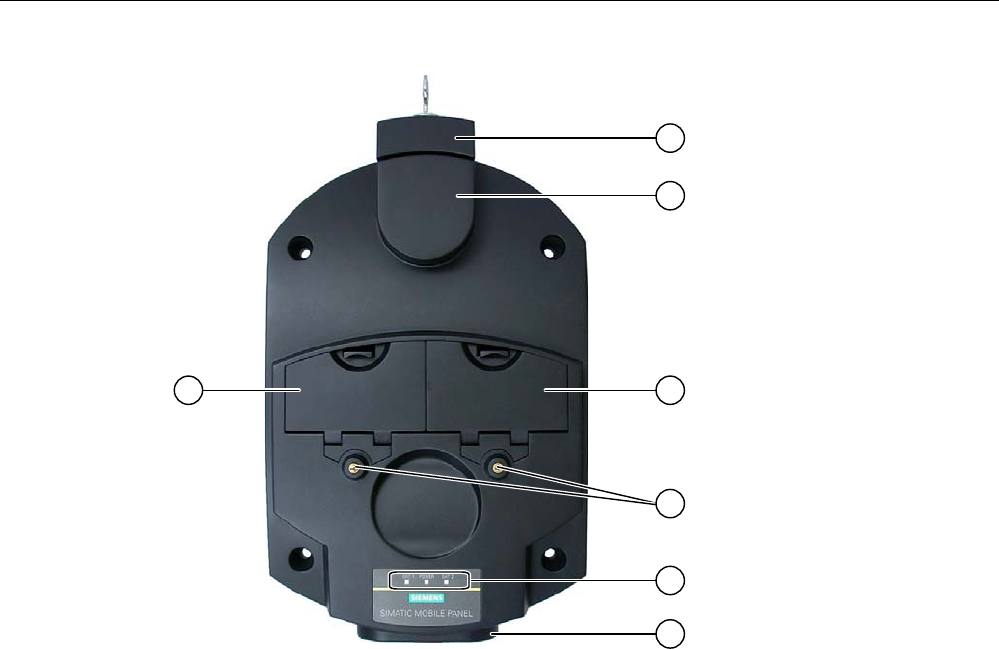
Rear view
On the reverse side you will find the type plate and approvals.

Overview
1.2 Design of the HMI device
Mobile Panel 277F IWLAN
20 Operating Instructions, 12/2007, A5E01003940-01
① Handle
② Connection bay cover
③ Connection for tabletop power supply unit
④ Battery compartment cover
⑤ Charging contacts for charging station
⑥ USB connector
The Mobile Panel 277F IWLAN can be securely hooked into a charging station.
1.2.2 Supplementary pack and other accessories
Accessory kit
The accessory kit is supplied with the HMI device.
The accessories pack for the HMI device contains the following:
● Main battery
● Bridging battery
● Cover cap with rubber seal
● Screws for fixing the cover cap
● Label for cover cap
● Function manual "Fail-safe operation of the Mobile Panel 277F IWLAN", in German
● CD
The CD includes:
– Function manual "Fail-safe operation of the Mobile Panel 277F IWLAN", in German,
English and Japanese
– F-FBs for the Mobile Panel 277F IWLAN
Additional documents may be enclosed with the accessory kit.
Protective foil
A protective foil kit for the HMI device can be ordered. Use order number 6AV6 671-5BC00-
0AX0.
The protective foil prevents the touch screen from being scratched or soiled.
Labeling strips
Labeling strips can be ordered as accessories. Use order number 6AV6 671-5BF00-0AX0.
Stickers for the cover caps can also be supplied, in addition to the labeling strips. The cover
caps cover the slot openings for the labeling strips.

Overview
1.2 Design of the HMI device
Mobile Panel 277F IWLAN
Operating Instructions, 12/2007, A5E01003940-01 21
Memory card
Note
Multimedia card
The multimedia card of the SIMATIC S7 PLC cannot be used.
Only use the SD memory cards or multimedia cards tested and approved by Siemens.
SIMATIC PC USB FlashDrive
The SIMATIC PC USB FlashDrive is a mobile form of data storage with a high data
throughput, designed for industrial use.
Main battery
The HMI device is designed to be operated by a battery.
The main battery can be ordered with the order number 6AV6 671-5CL00-0AX0.
Bridging battery
The bridging battery allows you to change the main battery during operation.
Charging station
The charging station is used to charge the battery in the HMI device and to safely store the
HMI device. You can also charge a main battery in each of the two charging compartments.
The charging station is designed to be used in the system.
The charging station can be ordered with the order number 6AV6 671-5CE00-0AX0.
Tabletop power supply unit
The tabletop power supply unit is only suitable for an office environment. You can operate
the HMI device with a tabletop power supply unit. The tabletop power supply unit, including
main supply conductors (EU, US, UK, Japan), can be ordered with the order number
6AV6 671-5CN00-0AX1.
Transponder
One or more transponders form zones in the system. The transponder can be ordered with
the order number 6AV6 671-5CM00-0AX0.
You can find more information about this on the Internet
at:http://mall.automation.siemens.com

Overview
1.2 Design of the HMI device
Mobile Panel 277F IWLAN
22 Operating Instructions, 12/2007, A5E01003940-01
1.2.3 Battery
Purpose
The HMI device is supplied with a main battery and a bridging battery.
Main battery and bridging battery
When fully charged, the main battery guarantees approximately 4 hours' operation time in
normal operation. After this time, the battery must be either changed or recharged.
You can change the main battery while the HMI device is operating. The bridging battery
supplies the power while the main battery is being changed.
While the power is being drawn from the bridging battery, the following features are
deactivated:
● Display backlighting
● Membrane keyboard
● Touch screen
● Function key LEDs
● Illuminated pushbuttons
● USB interface
Charging options
To charge the main battery, you have the following possibilities:
● In the HMI device while it is in the charging station
● In the charging compartment of the charging station
● In the HMI device when connected to the tabletop power supply unit
See also
Inserting, charging and changing the battery (Page 83)
Charging batteries in the charging compartment (Page 120)
1.2.4 Charging station
The following figure shows the charging station.
Overview
1.2 Design of the HMI device
Mobile Panel 277F IWLAN
Operating Instructions, 12/2007, A5E01003940-01 23
① Lock
② Hook for hooking in the HMI device
③ Charging compartment for one main battery each
④ Charging contacts for the HMI device
⑤ LED display
⑥ Power supply connection
Functions
The charging station performs the following functions:
● Charging the batteries in the charging compartments of the charging station
● Supplying power to the HMI device
● Charging the main battery fitted in the HMI device
● Safe storage of the HMI device
The lock prevents unauthorized removal of the HMI device from the charging station.
Accessory kit
The accessory kit is supplied with the charging station.
The accessory kit for the HMI device contains the following:
● Lock

Overview
1.3 Configuration and process control phase
Mobile Panel 277F IWLAN
24 Operating Instructions, 12/2007, A5E01003940-01
● Key set for lock
● Counterpart for power supply connector
Additional documents may be enclosed with the accessory kit.
See also
Charging station (Page 120)
1.3 Configuration and process control phase
Introduction
You must follow the phases below in order to use an HMI device in the system:
● Configuration phase
● Process control phase
Configuration phase
The HMI device project, which includes the plant screens, is created during the configuration
phase.
The following actions are carried out as part of the configuration phase:
● Creating the project
● Accepting the project (determining the checksum)
● Testing the project
● Simulating the project
● Backing up the project
After the configuration phase, the project is transferred to the HMI device by the configuring
PC.
&RQILJXULQJ3&
3URMHFW
0RELOH3DQHO),:/$1
Process control phase
Once the project is transferred to the HMI device, the operator operates and monitors current
processes in the process control phase. The HMI device is connected to a PLC in the plant
and exchanges values with this PLC. The plant screens on the HMI devices are used to
provide a clear overview of the active processes.
Overview
1.4 Transponder
Mobile Panel 277F IWLAN
Operating Instructions, 12/2007, A5E01003940-01 25
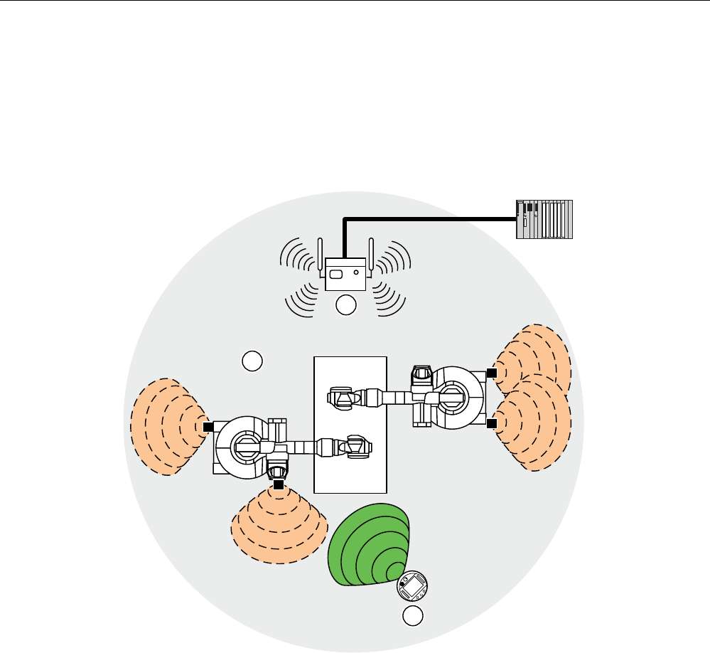
The following figure shows an example of a system structure with the
Mobile Panel 277F IWLAN.
6
(76
352),1(7
0RELOH3DQHO),:/$1
6&$/$1&(
$FFHVV3RLQW
6,0$7,&6)31'3DV
352),1(7,2FRQWUROOHU
)DLOVDIH,2DV
352),1(7,2GHYLFH
In the depicted configuration, each PROFINET IO device communicates with just one
PROFINET IO controller. In this example, the Mobile Panel 277F IWLAN communicates
exclusively with the F-CPU as the F-PROFINET IO controller.
See also
Operating a project (Page 231)
Preparing and backing up a project (Page 189)
1.4 Transponder
Forming effective ranges and zones with transponders
Transponders form effective ranges and zones. Effective ranges and zones are defined by
the maximum distance from one or more transponders.
Effective ranges
You can define effective ranges in your system.
An effective range is the range in which sections of the system, for example a machine, can
be operated with the enabling buttons of the HMI device.

Overview
1.4 Transponder
Mobile Panel 277F IWLAN
26 Operating Instructions, 12/2007, A5E01003940-01
Zones
You can divide your system into zones.
A zone is a physical range for operator control and monitoring which is registered by the HMI
device. Depending on the project design, the HMI device displays zone-specific process
displays and allows image objects to be operated in a zone-dependent manner.
Determining the current effective range and current zone
The assignment of transponders to effective ranges and zones is predefined in the project.
Each transponder has a unique ID. The transmitting range of the transponder approximates
to a lobe shape with a range of approximately 8 m.
Distances are measured as follows:
● The HMI device sends signals in the current project
● The transponder responds to the signal from the HMI device and sends its ID to the HMI
device
● The HMI device evaluates the ID and only measures the distance between it and the
configured transponder(s)
Thus the HMI device determines which effective range/zone it is currently in.
Installation and connection
You must install the transponders in the system such that the effective ranges and zones are
covered by the transmitting ranges of the relevant transponders.
The transponders are battery-operated.
System without effective ranges and zones
You can also operate the Mobile Panel 277F IWLAN in a system without effective ranges
and zones. In this case, no transponders are required in the system.
Accessory kit
The accessories pack is supplied with the transponder.
The accessories pack for the transponder contains the following:
● 3 AA mignon batteries, 1.5 V
Additional documents may be enclosed with the accessory kit.
See also
Distance measurement between HMI device and transponder (Page 61)
Setting transponder ID and inserting the battery (Page 66)
Effective ranges and zones (Page 58)
Radiation characteristic of the transponder (Page 314)
Overview
1.5 Ranges in the plant
Mobile Panel 277F IWLAN
Operating Instructions, 12/2007, A5E01003940-01 27
1.5 Ranges in the plant
WLAN range
The WLAN range is the range in the plant where the HMI device communicates with other
communication nodes over a wireless local area network.
352),VDIH
① Access point is the network transition from WLAN to LAN
② WLAN range in which communication with the access point is possible
③ Mobile panel in the WLAN range; the emergency stop button is active, the enabling buttons
are without function.
When the PROFIsafe communication between the controller and operator panel is
established in the WLAN range, the emergency stop button on the HMI device becomes
active.
Effective range
An effective range is the range in which sections of the system, for example a machine, can
be operated with the enabling buttons of the HMI device. A requirement for fail-safe
operation is that the HMI device is logged onto an effective range within the WLAN range.

Overview
1.6 Fail-safe operation
Mobile Panel 277F IWLAN
28 Operating Instructions, 12/2007, A5E01003940-01
Zones
In addition to the effective ranges you can define zones in your system. The zones are not
relevant for fail-safe operation. They are used merely to control the project depending on the
location of the operator. For example a picture change can be configured for zone entry or
zone exit.
Zones and effective range are independent of each other.
See also
Division of the system into effective ranges and zones (Page 58)
1.6 Fail-safe operation
Configuration tools and add-on packages
For fail-safe operation of the HMI device, the following software is required:
● STEP 7 V5.4 as of SP2
● SIMATIC S7 Distributed Safety as of V5.4 SP3
● WinCC flexible 2007
Fail-safe automation system
Fail-safe automation system (F systems) are used in plants requiring higher levels of safety.
F systems control processes in such a way that a safe state is achieved in every situation.
An immediate shutdown therefore does not pose a danger to people or the environment.
Fail-safe application of the HMI device
The Mobile Panel 277F IWLAN is a PROFINET IO device on Industrial Ethernet.
During fail-safe operation, the HMI device registers the signal states of the emergency stop
button and enabling button, and transmits corresponding safety message frames to the CPU.
The CPU and HMI device communicate with each other via the PROFIsafe fail-safe protocol.
The HMI device can operate in fail-safe mode conforming to SIL3/Ple/Cat. 4 if the safety
functions are appropriately configured in STEP 7 with the "S7 Distributed Safety" option
package.
To guarantee availability of the safety functions, particular fail-safe function blocks (F-FBs)
must be used in the safety program. The F-FBs are supplied on a CD together with the HMI
device.
Diagnostics function of the HMI device
HMI device diagnostics conforming to PROFINET IO standard IEC 61784-1:2002 Ed1 CP
3/3 are available for the standard application.

Overview
1.7 Functional scope with WinCC flexible
Mobile Panel 277F IWLAN
Operating Instructions, 12/2007, A5E01003940-01 29
The diagnostics function cannot be parameterized. The diagnostics are always activated and
are automatically made available by the HMI device in STEP 7 in the event of an error.
In addition to the safety-relevant part, the diagnostics function transfers the following
diagnostics:
● Communication error
Communication between the HMI device as I/O device and the F-CPU as I/O controller
has been interrupted (for example, due to incorrect PROFIsafe address or missing WLAN
connection).
1.7 Functional scope with WinCC flexible
The following tables show the objects that can be integrated into a project for a
Mobile Panel 277F IWLAN.
Note
The specified values are maximum values of the individual objects. Simultaneous use of
multiple objects with their maximum value can lead to problems in the active project.
Alarms
Object Specification Mobile Panel 277F IWLAN
Number of discrete alarms 4.000
Number of analog alarms 200
Length of the alarm text 80 characters
Number of tags in an alarm Max. 8
LEDs Alarm line, Alarm window,
Alarm view
Acknowledge error alarms individually Yes
Acknowledge several error alarms simultaneously
(group acknowledgment of alarm groups)
16 alarm groups
Edit alarm Yes
Alarm
Alarm indicator Yes
ALARM_S Display S7 alarms Yes
Alarm buffer capacity 512 alarms
Simultaneously queued alarm events Max. 250
View alarm Yes
Delete alarm buffer Yes
Alarm buffer retentive
Line-by-line printing of alarms Yes
Tags, values and lists

Overview
1.7 Functional scope with WinCC flexible
Mobile Panel 277F IWLAN
30 Operating Instructions, 12/2007, A5E01003940-01
Object Specification Mobile Panel 277F IWLAN
Tag Number 2.048
Limit value monitoring Input/Output Yes
Linear scaling Input/Output Yes
Text list Number 500 1)
Graphics list Number 400 1)
1) The maximum total of text and graphics lists is 500.
Screens
Object Specification Mobile Panel 277F IWLAN
Number 500
Fields per screen 200
Tags per screen 200
Complex objects per screen (for example bars) 10
Screen
Template Yes
Recipes
Object Specification Mobile Panel 277F IWLAN
Number 300
Data records per recipe 500
Entries per recipe 1.000
Recipe memory 64 KB
Recipe
Location1) • Memory card
• USB memory stick
• Network drive
1) The number of recipe data records might be restricted by the capacity of the storage medium.
Logs
Note
The HMI devices are suitable for the logging of relatively small volumes of data.
Manage the data in several adjacent archives in a segmented circular log. The use of a large
circular log has a negative effect on performance.

Overview
1.7 Functional scope with WinCC flexible
Mobile Panel 277F IWLAN
Operating Instructions, 12/2007, A5E01003940-01 31
Object Specification Mobile Panel 277F IWLAN
Number of logs 20
Number of sub-archives with segmented circular log 400
Entries in each log including all partial logs 10.000
Filing format CSV with ANSI character set
Logs
Location1) • Memory card
• USB memory stick
• Network drive
1) The number of entries in the log may be restricted by the capacity of the storage medium.
Safety
Object Specification Mobile Panel 277F IWLAN
Number of user groups 50
Number of users 50
User administration
Number of authorizations 32
Infotexts
Object Specification Mobile Panel 277F IWLAN
Length (no. of characters) 320
(depending on font)
For alarms Yes
For screens Yes
Infotext
For screen objects (for example for I/O field, switch,
button, invisible button)
Yes
Additional functions
Object Specification Mobile Panel 277F IWLAN
Monitor setting Touch screen calibration
Brightness setting
Yes
Yes
Language change Number of languages 16
User-specific extension of the functionality Yes VBScript
Number of scripts 50
Graphic object Vector and pixel graphics Yes
Trends Number 300
Task planner Number of tasks 48
Text objects Number 10.000
Direct keys PROFINET IO direct keys Yes

Overview
1.8 Software options
Mobile Panel 277F IWLAN
32 Operating Instructions, 12/2007, A5E01003940-01
Device-specific functions
Object Specification Mobile Panel 277F IWLAN
Battery Displaying battery status Yes
WLAN quality Displaying WLAN quality Yes
Effective range quality Displaying the effective range quality Yes
Effective range name Display effective range name Yes
Zone quality Displaying zone quality Yes
Zone name Displaying zone names Yes
1.8 Software options
The following software options are available for the HMI device:
● WinCC flexible/Sm@rtService
The Sm@rtService option enables you to access a remote HMI device from the HMI
device or PC via Ethernet. Access to the Mobile Panel 277F IWLAN is read-only.
● WinCC flexible/Sm@rtAccess
The Sm@rtAccess option enables you to set up communication between different HMI
systems.
● WinCC flexible /Audit
The /Audit option extends the HMI device to include functions for recording operations in
an audit trail and electronic signature.
1.9 Communication
Number of connections
Connection Mobile Panel 277F IWLAN
Maximum number of connections 6
Note
In the following cases, you must not enable PROFINET IO in the Control Panel:
• Use of PLCs from other manufacturers
PLCs that can be used for the Mobile Panel 277F IWLAN
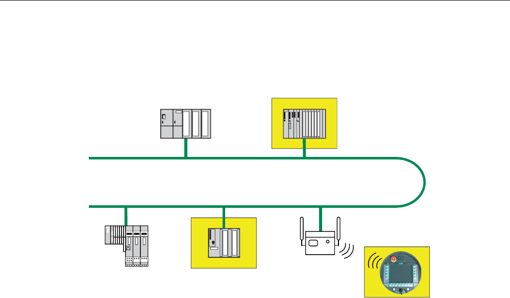
The HMI device has been enabled for use with the following type of PLC:

Overview
1.9 Communication
Mobile Panel 277F IWLAN
Operating Instructions, 12/2007, A5E01003940-01 33
● SIMATIC S7
● Allen-Bradley E/IP C.Logix
Note
A SIMATIC S7F is vital for fail-safe functionality. The HMI device cannot be operated
without fail-safe communication.
Protocols
The HMI device uses the following protocol for communication with the PLC:
● PROFIsafe Mode V2.0

Mobile Panel 277F IWLAN
Operating Instructions, 12/2007, A5E01003940-01 35
Safety instructions, standards and notes 2
2.1 Safety instructions
Safety regulations
WARNING
Injury or material damage
Strictly observe all instructions in this document at all times. Otherwise, hazardous
situations can arise or the safety functions integrated in the HMI device can be rendered
ineffective.
Observe the safety and accident prevention instructions applicable to your application in
addition to the safety instructions given in this manual.
Configuration requirements
WARNING
Injury or material damage
The configuration engineer for a machine or system PLC must take precautions to ensure
that an interrupted program can be restarted normally after communication errors, voltage
dips, or power failures.
Dangerous operating modes must not occur, not even temporarily, from the entire
sequence of the user program up to troubleshooting.
Proper use
WARNING
Commissioning of the HMI device is forbidden until it has been absolutely ensured that the
machine which is to be operated with the HMI device complies with Directive 98/37/EC.
Safety instructions, standards and notes
2.1 Safety instructions
Mobile Panel 277F IWLAN
36 Operating Instructions, 12/2007, A5E01003940-01
Fault-free operation
WARNING
Interference with other systems
When using the HMI device in accordance with DIN EN 13557 you must ensure that the
HMI device does not interfere with other systems at the site, or that other systems do not
interface with the HMI device.
Safety measures during operation
NOTICE
Non-functional emergency stop button
The emergency stop button must be checked periodically for proper function.
WARNING
HMI device failure
After a hard impact to the HMI device, check the safety-relevant features for functional
capability, for example in the event that the HMI device is dropped.
WARNING
Danger of injury
Manual movements controlled with the HMI should only be executed in conjunction with the
enabling buttons and at reduced velocity.
WARNING
Exclusive operating right
When operating the plant with the HMI device it is not permitted to operate the plant
concurrently from a different HMI device.
Prevent concurrent operation through appropriate configuration.
High frequency radiation
NOTICE
Unintentional operating situations
High-frequency radiation, for example from cellular phones, can lead to undesirable
operating situations.
Safety instructions, standards and notes
2.2 Standards, certificates and approvals
Mobile Panel 277F IWLAN
Operating Instructions, 12/2007, A5E01003940-01 37
2.2 Standards, certificates and approvals
Certifications
CAUTION
The following overview shows possible approvals.
The respective valid approvals for the HMI device itself, the charging station, power supply
unit and transponder are those shown on the rear panel.
CE approval
The HMI device, charging station, power supply unit, and transponder satisfy the
requirements and protection objectives of the EC Directives below. The HMI device,
charging station, power supply unit, and transponder comply with the harmonized European
standards (EN) published in the Official Journals of the European Union for programmable
controllers:
● 89/336/EEC Electromagnetic Compatibility Directive (EMC Directive)
● 98/37/EG Directive of the European Parliament and Council of 22 June 1998 on the
approximation of the laws and administrative regulations of the Member States
concerning machinery
● Specific absorption rate in accordance with EN 50932
EC Declaration of Conformity
The EC Declarations of Conformity are available to the relevant authorities at the following
address:
Siemens Aktiengesellschaft
Automation & Drives
A&D AS RD ST PLC
PO Box 1963
D-92209 Amberg, Germany
UL approval
Underwriters Laboratories Inc., to
● UL 508 (Industrial Control Equipment)
● CSA C22.2 No. 142 (Process Control Equipment)

Safety instructions, standards and notes
2.2 Standards, certificates and approvals
Mobile Panel 277F IWLAN
38 Operating Instructions, 12/2007, A5E01003940-01
The approval is only valid in the case of battery operation or when stationary in the charging
station.
Marking for Australia
N117
The HMI device, charging station, power supply unit, and transponder satisfy the
requirements of Standard AS/NZS 2064 (Class A).
Wireless approval
The HMI device wireless approvals for the various countries are located as follows:
● On the rear of the HMI device
● In the product information supplied together with the HMI device
BGIA
The BGIA confirms that the HMI device satisfies the requirements of the standards below
with regard to its safety functions.
● SIL3 in accordance with IEC 61508-1 to 4
● Category 4 in accordance with EN 954-1.
● Pl e and Cat. 4 in accordance with EN ISO 13849-1
● ISO 13850
● Principle for testing and certifying "Bus systems for the transmission of safety-related
information", GS-ET-26 Electrical Engineering Technical Committee, Edition 05.2002
● Principles for testing and certifying electromechanical enabling switches and devices,
GS-ET-22 Electrical Engineering Technical Committee, Edition 11.2005
TÜV
The TÜV confirms that the HMI device satisfies the requirements of the standards below with
regard to its safety functions.
● SIL3 in accordance with IEC 61508-1 to 4
● Category 4 in accordance with EN 954-1.
● Pl e and Cat. 4 in accordance with EN ISO 13849-1
● EN 60204-1

Safety instructions, standards and notes
2.3 Operating safety
Mobile Panel 277F IWLAN
Operating Instructions, 12/2007, A5E01003940-01 39
● ISO 13850
● IEC 62061
● 98/37/EC
Requesting certificates
Copies of the certificates and associated reports can be requested from the following
address:
Siemens Aktiengesellschaft
Automation & Drives
A&D AS RD ST
PO Box 1963
D-92209 Amberg, Germany
2.3 Operating safety
Standards
The HMI device complies with the following standards:
● EN 954-1
Safety of machinery
● EN 60204-1
Safety of machinery – Electrical equipment of machines
● EN 62061
Safety of machinery – Functional safety of safety-related electrical, electronic and
programmable electronic control systems
● EN ISO 13849-1
Development, testing and certification of safety-related machine controls
● ISO 13850
Safety of machinery – Emergency stop – Principles for design
● IEC 61508
Functional safety of electrical/electronic/programmable electronic-related systems
● EN 61131-1 and EN 61131-2
Programmable Controllers
● The HMI device was tested for EMC in accordance with the following standards:
– EN 61000-6-4, Generic standard – emitted interference
– EN 61000-6-2, Generic standard, Immunity, industrial environments
– EN 61131-2, Programmable Controllers
Safety instructions, standards and notes
2.4 Power supply
Mobile Panel 277F IWLAN
40 Operating Instructions, 12/2007, A5E01003940-01
● EN 300 328 V1.6.1, EN 300 440-1 V1.3.1, EN 301 893, EN 301 489-1, EN 301 489-17,
FCC Part 15.245, 15.247, 15.407
Wireless approval
● EN 50 360, IEEE 1528-X, EN 50371, EN 50 392
Radiation protection requirements (SAR/EMF)
If the HMI device is used in a system, the following standards are fulfilled:
● prEN 1921, Industrial automation systems – safety of integrated manufacturing systems
● EN 12417:2001, Machine tools – safety – machining centers
● UL 508, Industrial Control Equipment
● CSA C22.2 No.14, Industrial Control Equipment
2.4 Power supply
Safety specifications
CAUTION
Damage to the HMI device
Only operate the HMI device with approved components:
• Batteries
• Charging station
• Tabletop power supply unit
http://mall.automation.siemens.com
WARNING
Injury or material damage
The HMI device should only be operated in the plant with the battery or in the charging
station. Operation with the tabletop power supply is not permitted in the plant.
WARNING
Effectiveness of the emergency stop button
The emergency stop button only becomes active when the HMI device is integrated into the
safety program.
Safety instructions, standards and notes
2.4 Power supply
Mobile Panel 277F IWLAN
Operating Instructions, 12/2007, A5E01003940-01 41
Charging station
WARNING
Injury or material damage
The charging station complies with the following standards:
• EN 50335-2-29
• DIN EN 60204-1
• Protection class III in accordance with EN 61131-2 or EN 50178.
The 24 VDC power supply must be ensured by safely isolating the low voltage from
hazardous voltages, for example by using a safety transformer or equivalent equipment.
Protect the power supply circuit with a 7 A fuse.
Allowance should be made for the loss of voltage on the connection cable during
dimensional analysis of the supply!
Please refer to the technical data for the supply voltage requirements.
WARNING
Injury or material damage
Configure the 24 VDC supply for the charging station correctly, otherwise components of
your automation system can be damaged and persons may be injured.
Use only voltage generated as protective extra-low voltage (PELV) for the 24 VDC supply
of the charging station.
CAUTION
Safe electrical separation
Use only power supply units with safety isolation complying with IEC 60364-4-41 or
HD 384.04.41 (VDE 0100, Part 410), for example according to the PELV standard, for the
charging station's 24 VDC supply.
The supply voltage must be within the specified voltage range. Malfunctions in the charging
station may otherwise result.
Applies to non-isolated system design:
Connect the connection for GND 24 V from the 24 V power supply output to equipotential
bonding for uniform reference potential.
Tabletop power supply unit
CAUTION
Please note that the mains connector must be removed for a complete disconnection from
the mains.

Safety instructions, standards and notes
2.5 Notes about usage
Mobile Panel 277F IWLAN
42 Operating Instructions, 12/2007, A5E01003940-01
Do not operate the HMI device in the plant with the table power supply unit.
The tabletop power supply unit is only suitable for an office environment.
The device is designed for operation on grounded power supply networks (TN systems to
VDE 0100, Part 300, or IEC 364-3).
Operation is not authorized on ungrounded or impedance-grounded power networks (IT
networks).
2.5 Notes about usage
Using the HMI device
A list indicating in which country or in which geographical region of a country the HMI device
can be used is included in the product information supplied with the HMI device.
Use in industry
The HMI device is designed for industrial use. For this reason, the following standards are
met:
● Interference emission requirements, paragraph 7.3, DIN EN 60947-1, Environment A
● Interference immunity requirements DIN EN 61326
Residential use
If the HMI device is used in a residential area, you must take measures to achieve Limit
Class B conforming to EN 55011 for RF interference.
A suitable measure for achieving the required RF interference level for Limit Class B
includes for example:
● Use of filters in electrical supply lines
Individual acceptance is required.
Use of cable-free control equipment
WARNING
When using cable-free control equipment you must ensure that it does not interfere with
other systems at the site, or that other systems do not interfere with it.

Safety instructions, standards and notes
2.6 Risk analysis
Mobile Panel 277F IWLAN
Operating Instructions, 12/2007, A5E01003940-01 43
2.6 Risk analysis
Carrying out a risk analysis
The following standards must be used to perform the risk analysis:
● EN ISO 12100-1 and EN ISO 12100-2, General design guidelines for machines
● EN 1050 Risk Assessment for Machinery
● EN 954-1 Safety of Machinery
These considerations result in a safety category (B, 1, 2, 3, 4) in accordance with EN 954-1
that ultimately dictates how the safety-related aspects of the system that will be configured
must be furnished.
With the safety-related parts of the Mobile Panel 277F IWLAN the following requirements are
satisfied:
● Category 4 in accordance with EN 954-1.
● SIL 3 in accordance with IEC 61508
● Pl e and Cat. 4 in accordance with EN ISO 13849-1
The risk assessment must take into account that the overall concept of the plant must be
configured accordingly. More detailed instructions on risk assessment and risk reduction are
provided in the system manual "Safety Integrated".
See also
Safety-related operator controls (Page 100)
2.7 Safety functions of the emergency stop button
Safety instructions
There is an emergency stop button on the Mobile Panel 277F IWLAN.
The emergency button on the Mobile Panel 277F IWLAN brings about a safety-related stop
of the configured system in accordance with EN 60204-1:1997, Section 9.2.5.3. You have
the option of implementing a Category 0, 1, or 2 Stop function in accordance with EN 60204-
1: 1997, Section 9.2.2. The stop function category must be selected on the basis of a risk
assessment.
WARNING
Emergency stop button not available
The emergency stop button on the HMI device must not used as a replacement for a
permanently-wired emergency stop/emergency off on the machine. Install stationary
emergency stop buttons that are available at all times on the configured system.
Safety instructions, standards and notes
2.8 Enabling button
Mobile Panel 277F IWLAN
44 Operating Instructions, 12/2007, A5E01003940-01
WARNING
Effectiveness of the emergency stop button
The following requirements must be met in order to render the emergency stop button
effective:
• The HMI device must be operated in the charging station or operated with the battery.
• The project must be running on the Mobile Panel 277F IWLAN.
• The HMI device must be integrated in the safety program of the F-CPU.
If these prerequisites are satisfied the following applies:
• The "SAFE" LED on the HMI device is illuminated.
• The emergency stop button of the Mobile Panel 277F IWLAN is effective.
Category 0 or 1 Stop
If a Category 0 or 1 Stop circuit is implemented, the stop function must be in effect
regardless of the operating mode. A Category 0 Stop must have precedence. Release of
the emergency stop button should not cause a hazardous situation (see also EN
60204:1997 chapter 9.2.5.3).
The stop function is not to be used as a replacement for safety equipment.
Storing the HMI device
WARNING
Non-functional emergency stop button
If the HMI device is not integrated, the emergency stop button does not function.
To avoid confusion between effective and non-effective emergency stop buttons, only one
integrated HMI device should be freely accessible.
If the HMI device is not in use, it must be stored in a locked area.
See also
Emergency stop button (Page 100)
2.8 Enabling button
Introduction
The enabling device consists of the two enabling buttons mounted on both sides of the
Mobile Panel 277F IWLAN.
Numerically controlled machines and systems are equipped with the operating modes
"Automatic mode" and "Special mode".
Safety instructions, standards and notes
2.8 Enabling button
Mobile Panel 277F IWLAN
Operating Instructions, 12/2007, A5E01003940-01 45
Safety is ensured in automatic mode by means of closed, isolating protective devices and/or
with functional non-isolating protective devices that block access.
In special mode, safety has to be ensured in a different manner than in automatic mode. In
special mode, the danger zones of the machine or system are entered, where controlled
movements have to be possible.
Special mode
A reduced speed on the machine or in the system has to be specified for special mode
based on the risk assessment. Movement of the machine should only be possible when the
enabling device is activated. The operator must have the necessary qualifications and be
acquainted with the details of the intended application.
Safety instructions
The safety-related aspects of the velocity reduction control and those for the enabling device
are designed in such a way that they satisfy the EN 954-1 safety category determined by the
risk analysis.
The operating principles of enabling devices are described in EN 60204. Through the
findings from accident investigations and the existence of technical solutions, the 3-stage
enabling button became state of the art. Positions 1 and 3 of the enabling button are Off
functions. Only the middle position allows the enabling function. EN 60204-1:1997 is
identical to IEC 60204-1, whereby the 3-stage enabling button is gaining international
importance.
The Stop category of the enabling device must be selected on the basis of a risk assessment
and correspond to a Category 0 or 1 Stop.
WARNING
Injury or material damage
Enabling buttons should only be used when the following applies for the person activating
the enabling button:
• The person can see the danger zone.
• The person is capable of recognizing personal injury hazards in good time.
• The person is capable of taking immediate measures to avoid danger.
The only person allowed to remain in the danger zone is the person who is activating the
enabling button.
Commands for unsafe conditions are not permitted to be issued with one enabling button
alone. For this purpose, a secondary, intentional start command by means of a button on
the Mobile Panel 277F IWLAN is required.
If you leave the effective range only briefly for a time period of up to 30 seconds while the
enabling button is pressed, the following occurs: 5 seconds after the effective range is left,
the enabling function is revoked.
If you enter the effective range again within 30 seconds, the enabling button must be
released and pressed again in order to reactivate enabling.

Safety instructions, standards and notes
2.9 Electromagnetic compatibility
Mobile Panel 277F IWLAN
46 Operating Instructions, 12/2007, A5E01003940-01
Note
Enabling button not effective
The enabling button is only effective if the HMI device is logged onto the effective range and
the "RNG" LED on the HMI device lights up.
If the operator leaves the effective range, the enabling button is deactivated after 5 seconds.
After 30 seconds the "Effective range exited without logoff" dialog box opens. The
LED "RNG" only goes out when the operator has confirmed this dialog box.
Risk from improper use
To avoid the danger of unauthorized use of the enabling button due to impermissible hold-
down, on each project start the enabling button must be pressed all the way down, and then
released.
2.9 Electromagnetic compatibility
Introduction
The HMI device, the charging station, the transponder, and the power supply satisfy, among
other things, the requirements of the EMC laws pertaining to the European domestic market.
The enhanced testing and limit value levels defined by CDV 61326-3-1/Ed. 1 have been
taken into account during the type test
EMC-compliant installation
Conditions for fault-free operation include EMC-compatible assembly of the charging station
and the use of interference-proof cables. The "Directives for interference-proof installation of
PLCs" and the "SIMATIC NET, Fundamentals of Industrial WLAN" manual also apply to the
assembly of the charging station.
Pulse-shaped interference
The following table shows the electromagnetic compatibility of modules with regard to pulse-
shaped interference.
Pulse-shaped
interference
Checked with
Applies to charging station with or without plugged-
on HMI device and power supply unit (230 VAC)
Degree of severity
Electrostatic discharge
in accordance with IEC
61000-4-2
Air discharge: 8 kV
Contact discharge: 6 kV
3
Bursts
(high-speed transient
interference)
in accordance with
IEC 61000-4-4
2 kV supply line
3

Safety instructions, standards and notes
2.9 Electromagnetic compatibility
Mobile Panel 277F IWLAN
Operating Instructions, 12/2007, A5E01003940-01 47
Pulse-shaped
interference
Checked with
Applies to charging station with or without plugged-
on HMI device and power supply unit (230 VAC)
Degree of severity
High-power surge pulses in accordance with IEC 61000-4-5, external protective circuit required (refer
to S7-300 PLC, Installation, chapter “Lightning and overvoltage protection”)
• Asymmetrical
coupling 2 kV power cable
DC voltage with protective elements
3
• Symmetrical coupling 1 kV power cable
DC voltage with protective elements
3
Sinusoidal interference
The following table shows the EMC behavior of the modules with respect to sinusoidal
interference.
Sinusoidal interference Test values
Applies to HMI device, charging station, and power
supply unit:
Degree of
severity
HF radiation (in
electromagnetic fields) in
accordance with
IEC 61000-4-3
80% amplitude modulation at 1 kHz
• To 10 V/m in the range 80 MHz to 1 GHz
• To 10 V/m in the range 1.4 GHz to 2 GHz
• To 1 V/m in the range 2 GHz to 2.7 GHz
3
HF conductance on
cables and cable shields
in accordance with IEC
61000-4-6
Test voltage 10 V, with 80% amplitude modulation of 1
kHz in the range 9 kHz to 80 MHz
3
Emission of radio interference
The following table shows the unwanted emissions from electromagnetic fields in
accordance with EN 55011,
Limit Value Class A, Group 1, measured at a distance of 10 m.
30 MHz to 230 MHz < 40 dB (V/m) quasi-peak
230 MHz to 1000 MHz < 47 dB (V/m) quasi-peak
Additional measures
Before you connect the HMI device to the public network, ensure that it is compliant with
Limit Class B in accordance with EN 55022.
Specific absorption rate SAR
Recommendation 1999/519/EC; Exposure of the public to EMF
Limit values for Europe in accordance with EN 50932
Limit values for USA in accordance with FCC OET Bulletin 65 Supplement C

Safety instructions, standards and notes
2.10 Transport and storage conditions
Mobile Panel 277F IWLAN
48 Operating Instructions, 12/2007, A5E01003940-01
● 2.0 W/kg within 10 g of tissue (in accordance with ICNIRP guideline)
● 1.6 W/kg within 1 g of tissue (in accordance with IEEE/FCC)
2.10 Transport and storage conditions
Mechanical and climatic transport conditions
The shipping conditions of this HMI device exceed requirements in accordance with IEC
61131-2. The following specifications apply to devices that are shipped and stored in the
original packaging.
The climatic conditions comply with the following standard:
● IEC 60721-3-2, Class 2K4 for transport
The mechanical conditions are compliant with IEC 60721-3-2, Class 2M2.
The following table shows the transport and storage conditions for the HMI device, charging
station, tabletop power supply unit and transponder.
Type of condition Permitted range
Drop test (in transport package) ≤ 1 m
Temperature From –20 to +60 °C
Atmospheric pressure From 1,080 hPa to 660 hPa,
corresponds to an elevation –1,000 to 3.500 m
Relative humidity Applies to HMI device:
From 10% to 90%, without condensation
Applies to charging station and transponder
from 35% to 85%, without condensation
Sinusoidal vibration in accordance with
IEC 60068-2-6
5 Hz to 9 Hz: 3.5 mm
9 Hz to 500 Hz: 9.8 m/s2
Shock in accordance with IEC 60068-2-29 250 m/s2, 6 ms, 1,000 shocks
NOTICE
Device failure
In the following cases, ensure that no moisture (dew) can settle on or in the HMI device,
charging station or transponder:
• Transportation of the HMI device in low temperatures
• Under extreme temperature variations
The HMI device must have acquired room temperature before it is put into operation. Do
not expose the HMI device to direct radiation from a heater in order to warm it up. If dewing
has developed, wait approximately four hours until the HMI device has dried completely
before switching it on.
The following points must be adhered to in order to ensure a fault-free and safe operation of
the HMI device:

Safety instructions, standards and notes
2.10 Transport and storage conditions
Mobile Panel 277F IWLAN
Operating Instructions, 12/2007, A5E01003940-01 49
● Proper transportation and storage
● Proper installation and mounting
● Careful operation and maintenance
The warranty for the HMI device will be deemed void if these stipulations are not heeded.

Mobile Panel 277F IWLAN
Operating Instructions, 12/2007, A5E01003940-01 51
Planning application 3
3.1 Application and ambient conditions
Mechanical and climatic conditions of use
The HMI device is designed for use in a location protected from the effects of the weather.
The conditions of use are compliant with requirements to DIN IEC 60721-3-3:
● Class 3M3 (mechanical requirements)
The table applies to the HMI device, charging station and transponder.
Tested for Test standard Comments
Sinusoidal
vibration,
stationary
DIN IEC 60721-3-3 Frequency range:
2 ≤ f ≤ 200 Hz
Deflection:
1.5 mm/5 m/s2
Shocks, non-
stationary,
Total shock
response
spectrum
DIN IEC 60721-3-3 Shock amplitude: 70 g
shock duration: 22 ms
● Class 3K3 (climatic requirements)
The table applies to the HMI device, charging station and transponder.
Ambient conditions Permitted range Comments
Air temperature 5 to 40 °C
Relative humidity 5 to 85 %,
no condensation
Corresponds to relative humidity, load
degree 2 in accordance with IEC 61131,
part 2
Absolute humidity 1 to 25 g/m3
Atmospheric pressure 70 to 106 kPa Corresponds to an elevation of up to
3,000 m
Use with additional measures
In the following cases the use of the HMI device requires additional measures:
● In locations with a high degree of ionizing radiation
● In locations with difficult operating conditions, for example due to:

Planning application
3.1 Application and ambient conditions
Mobile Panel 277F IWLAN
52 Operating Instructions, 12/2007, A5E01003940-01
– Corrosive vapors, gases, oils or chemicals
– Electrical or magnetic fields of high intensity
● In systems that require special monitoring, for example:
– Elevators
– Systems in especially hazardous rooms
Testing for mechanical environmental conditions in accordance with GS-ET-22
The following table provides information on the type and scope of tests for mechanical
ambient conditions.
The table applies to the HMI device, charging station and transponder.
Tested for Test standard Comments
Vibrations IEC 60068, part 2–6
(sinusoidal)
Test principles GS-ET-22
Type of vibration:
20 frequency cycles with a tuning rate of
1 octave/minute.
Frequency range in accordance with GS-ET-22:
10 ≤ f ≤ 150 Hz, ± 1 Hz
Deflection:
0.35 mm / 5 g ± 15 % at the control point
Shock IEC 60068, Part 2–27 Shock form: Half-sinus
Shock amplitude: 30 g
Shock duration: 11 ms
Number of shocks: 3 per axis
Continuous shocks IEC 60068, Part 2–29 Shock form: Half-sinus
Shock amplitude: 10 g
Shock duration: 16 ms
Shock cycle: (1–3)/s
Number of shocks: 1000 ± 10
Impact IEC 60068, Part 2–75 One-time impact stress of 1 Nm with an impact
test device similar to DIN VDE 0740, Part 1,
Section 19.2 at room temperature.
The table only applies to the HMI device, with and without battery.
Tested for Test standard Comments
Falling Drop testing in accordance
with
EN 60068-2-32
1.2 m
Reducing vibrations
If the HMI device is subjected to greater shocks or vibrations, you must take appropriate
measures to reduce acceleration or amplitudes.
We recommend fitting the charging station of the HMI device to vibration-absorbent material
(on metal shock absorbers, for example).

Planning application
3.1 Application and ambient conditions
Mobile Panel 277F IWLAN
Operating Instructions, 12/2007, A5E01003940-01 53
Climatic ambient conditions for the HMI device
The following table shows the permitted climatic ambient conditions for use of the HMI
device:
Ambient conditions Permitted range Comments
Temperature
• Operation
• Storage/transport
• 0 to 40 °C
• –20 to 60 °C
Relative humidity 5 to 85 %,
no condensation
Corresponds to relative humidity, load
degree 2 in accordance with IEC 61131,
part 2
Atmospheric pressure 1.060 hPa to 700 hPa Corresponds to an elevation of –1,000
to 2,000 m
SO2: < 0.5 vpm;
Relative humidity < 60 %, no
condensation
Check: 10 cm3/m3; 10 days Pollutant concentration
H2S: < 0.1 vpm;
Relative humidity < 60 %, no
condensation
Check: 1 cm3/m3; 10 days
Climatic ambient conditions for the charging station
The following table shows the permitted climatic ambient conditions for use of the charging
station.
Ambient conditions Permitted range Comments
Temperature
• Operation
• Storage/transport
• From 0 to 40 °C
• From –20 to 60 °C
Relative humidity 5 to 85 %,
no condensation
Corresponds to relative humidity, load
degree 2 in accordance with IEC 61131,
part 2
Atmospheric pressure 1.060 hPa to 700 hPa Corresponds to an elevation of –1,000
to 2,000 m
SO2: < 0.5 vpm;
Relative humidity < 60 %, no
condensation
Check: 10 cm3/m3; 10 days
Pollutant concentration
H2S: < 0.1 vpm;
Relative humidity < 60 %, no
condensation
Check: 1 cm3/m3; 10 days
Ambient climatic conditions for the transponder
The following table shows the permitted climatic ambient conditions for use of the
transponder:
Planning application
3.2 Mounting location and clearance of charging station
Mobile Panel 277F IWLAN
54 Operating Instructions, 12/2007, A5E01003940-01
Ambient conditions Permitted range Comments
Temperature
• Operation
• Storage/transport
• 0 to 50 °C
• –20 to 60 °C
Relative humidity 5 to 85 %,
no condensation
Corresponds to relative humidity, load
degree 2 in accordance with IEC 61131,
part 2
Atmospheric pressure 1.060 hPa to 700 hPa Corresponds to an elevation of –1,000
to 2,000 m
SO2: < 0.5 vpm;
Relative humidity < 60 %, no
condensation
Check: 10 cm3/m3; 10 days Pollutant concentration
H2S: < 0.1 vpm;
Relative humidity < 60 %, no
condensation
Check: 1 cm3/m3; 10 days
3.2 Mounting location and clearance of charging station
Selecting a mounting location for the charging station
The charging station is designed for vertical installation.
WARNING
Emergency stop button not effective
If the HMI device is not integrated, the emergency stop button does not function.
The charging station must be installed in either a system area with sufficiently wide WLAN
coverage or a separate service area. If the charging station is in the system and the HMI
device is hooked into the charging station, the emergency stop button must be effective.
To avoid confusion between effective and non-effective emergency stop buttons, only one
integrated HMI device should be freely accessible.
CAUTION
System or machine stop
The HMI device can fall down if it is not securely hooked in. The emergency stop button on
the HMI device can also be triggered unintentionally.
In order to ensure that the HMI device can be hooked in securely, select a vertical surface
or one inclined slightly to the rear as the mounting surface.

Planning application
3.2 Mounting location and clearance of charging station
Mobile Panel 277F IWLAN
Operating Instructions, 12/2007, A5E01003940-01 55
NOTICE
Battery cannot be charged
To charge the batteries, the ambient temperature/battery temperature must not exceed 40
°C. The higher the temperature, the longer it will take for the battery to charge.
Find a place with a cool ambient temperature for the charging station. If necessary, allow
the battery to cool first.
Note
Positioning
Observe the following points when selecting the mounting location:
• Do not mount the charging station directly below an Access Point.
• The display must not be exposed to direct sunlight
• Ergonomic mounting height
The position must satisfy the following conditions:
– Ergonomic operation of the HMI device while it is in the charging station
– Ease of insertion of the HMI device into the charging station and removal from the
charging station
Maintaining clearances
The following clearance is required around the charging station:
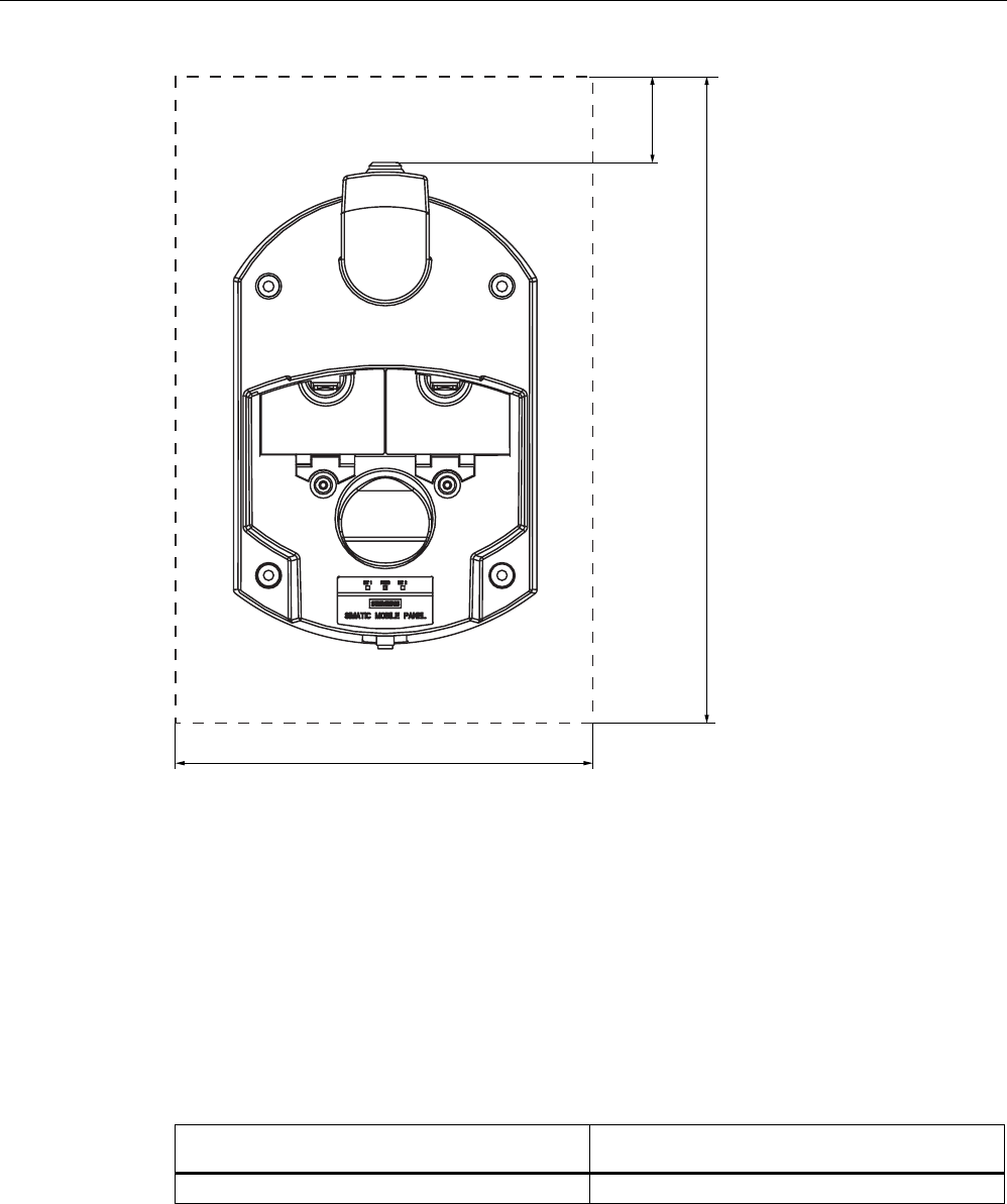
Planning application
3.3 Information on insulation tests, protection class and degree of protection
Mobile Panel 277F IWLAN
56 Operating Instructions, 12/2007, A5E01003940-01
$OOGLPHQVLRQVLQPP
3.3 Information on insulation tests, protection class and degree of
protection
Test voltages
Insulation strength is demonstrated in the type test with the following test voltages in
accordance with IEC 61131-2:
Circuits with a nominal voltage of Ue to other
circuits or ground
Test voltage
< 50 V 500 VDC

Planning application
3.4 Rated voltages
Mobile Panel 277F IWLAN
Operating Instructions, 12/2007, A5E01003940-01 57
Protection against foreign objects and water
Note
The HMI device only complies with the quoted safety classes if the plugs in the cable entries
have sealing caps.
Degree of protection in accordance with
IEC 60529
Description
Front panel and rear panel HMI device:
• IP65
For the charging station and transponder:
• IP65
3.4 Rated voltages
The following table shows the permissible rated voltage and the relevant tolerance range for
the charging station.
Nominal voltage Tolerance range
+24 VDC 19.2 V to 28.8 V (–20%, +20%)
The following table shows the possible, permissible rated voltage for the tabletop power
supply unit.
Nominal voltage Tolerance range
230 VAC 170 to 264 V
120 VAC 85 to 132 V
3.5 Required properties of the WLAN connection
Please observe the installation guidelines when installing the WLAN network. Further
information on this is available in the system manual "Fundamentals of industrial wireless
LAN", in the "Network architecture" chapter.
NOTICE
As a basic principle, WLAN in accordance with IEEE 802.11 a should be used with the
Mobile Panel 277F IWLAN.
We recommend you not to use roaming in applications with PROFIsafe communication.

Planning application
3.6 Effective ranges and zones
Mobile Panel 277F IWLAN
58 Operating Instructions, 12/2007, A5E01003940-01
Ad hoc mode
Ad hoc mode cannot be used in conjunction with the Mobile Panel 277F IWLAN.
See also
Description of interfaces on the HMI device (Page 313)
3.6 Effective ranges and zones
3.6.1 Division of the system into effective ranges and zones
Effective ranges
Safety-related operator inputs are only possible in a limited area upstream of a machine or
system. This is known as the effective range. The effective range assumes that the operator
has a clear view the machine without any obstructions. To perform safety-related operator
inputs, the operator must log the HMI device onto the effective range.
Note
You can also operate the HMI device without any effective ranges being defined in the
system.
Note
Zones and effective ranges are completely independent of each other.
Rules for effective ranges
A maximum for 127 effective ranges can be defined for each project. An effective range
requires at least one transponder. An effective range can be formed by a maximum of 127
transponders. Effective ranges must not overlap.
An effective range is defined by the maximum distance of the HMI device from one or more
transponders. The same maximum distance applies to all transponders in an effective range.
The assignment of transponders to effective ranges is predefined in the project.
Example
The following figure shows an example with three effective ranges.
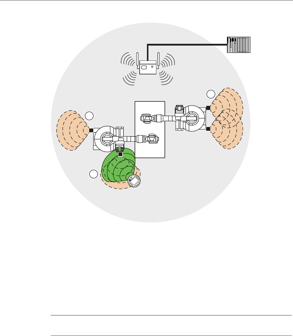
Planning application
3.6 Effective ranges and zones
Mobile Panel 277F IWLAN
Operating Instructions, 12/2007, A5E01003940-01 59
352),VDIH
① Effective range 1, formed by a transponder
② Effective range 2, formed by two transponders
③ The Mobile Panel is in effective range 3.
Zones
The system can be divided into different zones. A zone might be where part of a particular
industrial process is carried out, for example assembly of parts. Zone-specific process
displays and possible operations can be configured in the project.
Note
You can also operate the HMI device without any zones being defined in the system.
Rules governing zones
A maximum of 254 zones is possible. A zone requires at least one transponder. A zone can
be formed by a maximum of 255 transponders. Zones must not overlap.
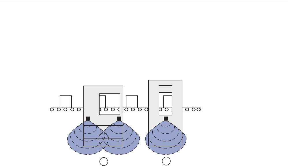
Planning application
3.6 Effective ranges and zones
Mobile Panel 277F IWLAN
60 Operating Instructions, 12/2007, A5E01003940-01
A zone is defined by the maximum distance of the HMI device from one or more
transponders. The same maximum distance applies to all transponders in a zone. The
assignment of transponders to zones is defined in the project.
Example
The figure below shows an example with two zones:
① Zone 1, formed by 2 transponders
② Zone 2, formed by 1 transponder
Transponder
Each transponder has a unique ID. The transmitting range of the transponder approximates
to a lobe shape with a range of approximately 8 m.
The ID is set directly on the transponder. The set ID must match the project
parameterization.
Distances are measured as follows:
● The HMI device sends signals in the current project
● The transponder responds to the signal from the HMI device and sends its ID to the HMI
device
● The HMI device measures the distance between it and the transponder(s).
Thus the HMI device determines which effective range/zone it is currently in.
Rules governing transponders
The following rules apply to assigning transponders:
● A transponder can only be assigned to one zone.
● A transponder can only be assigned to one effective range.
● A transponder can be assigned to a zone and an effective range simultaneously.
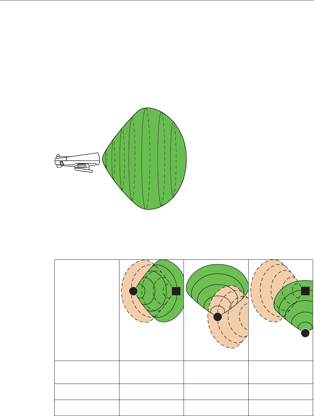
Planning application
3.6 Effective ranges and zones
Mobile Panel 277F IWLAN
Operating Instructions, 12/2007, A5E01003940-01 61
See also
Ranges in the plant (Page 27)
3.6.2 Distance measurement between HMI device and transponder
The transmitting range of the transponder and the receiving area of the HMI device
approximate to a lobe shape with a range of approximately 8 m. More information can be
found in chapter Radiation characteristic (Page 314) .
Distance measurement between the HMI device and the transponder is only possible if both
devices are within the other's receiving area. The table below shows when distance
measurement is feasible. In the figures, the HMI device is shown as a circle and the
transponder as a square.
HMI device in
transponder's
transmitting range
Yes Yes No
Transponder in HMI
device's receiving area
Yes No Yes
Result Distance measurement
successful
Distance measurement
not possible
Distance measurement
not possible
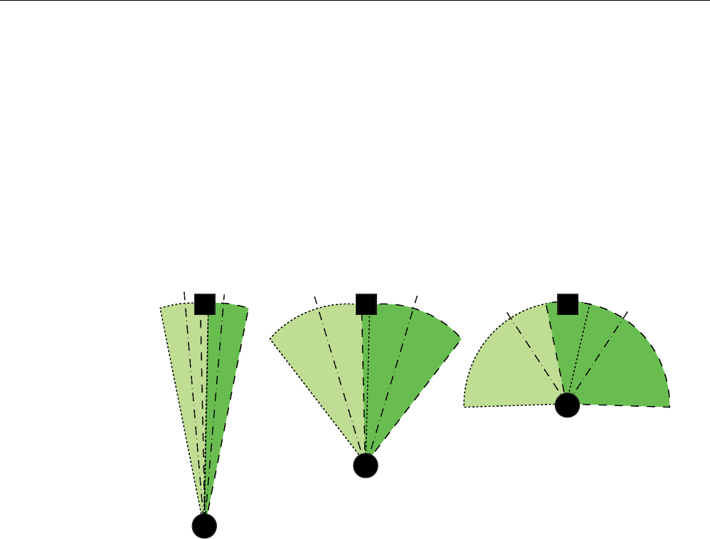
Planning application
3.6 Effective ranges and zones
Mobile Panel 277F IWLAN
62 Operating Instructions, 12/2007, A5E01003940-01
Aligning the HMI device to the transponder
You must align the HMI device to the transponder to enable them to recognize one another.
The further away the HMI device is from the transponder, the more accurately it and,
therefore, the antennae's main direction of radiation, must be aligned to the transponder. It is
only permissible to turn the HMI device very slightly.
The closer the HMI device is to the transponder, the further you can turn the HMI device
away from the transponder.
At a distance of 8 m, the permissible angle of deviation is about 20°. At a distance of 4 m,
the permissible angle of deviation is about 110 °.
The figure below shows an example of the possible angle of rotation in relation to the
distance from the transponder.
See also
Transponder (Page 25)
3.6.3 Planning effective ranges
Effective range and transponder
An effective range is formed physically by transponders. Transponders must be mounted in
the perimeter around the machine in such a manner that the planned effective range is
covered by the transmitting range of the transponders assigned to it.
Example:
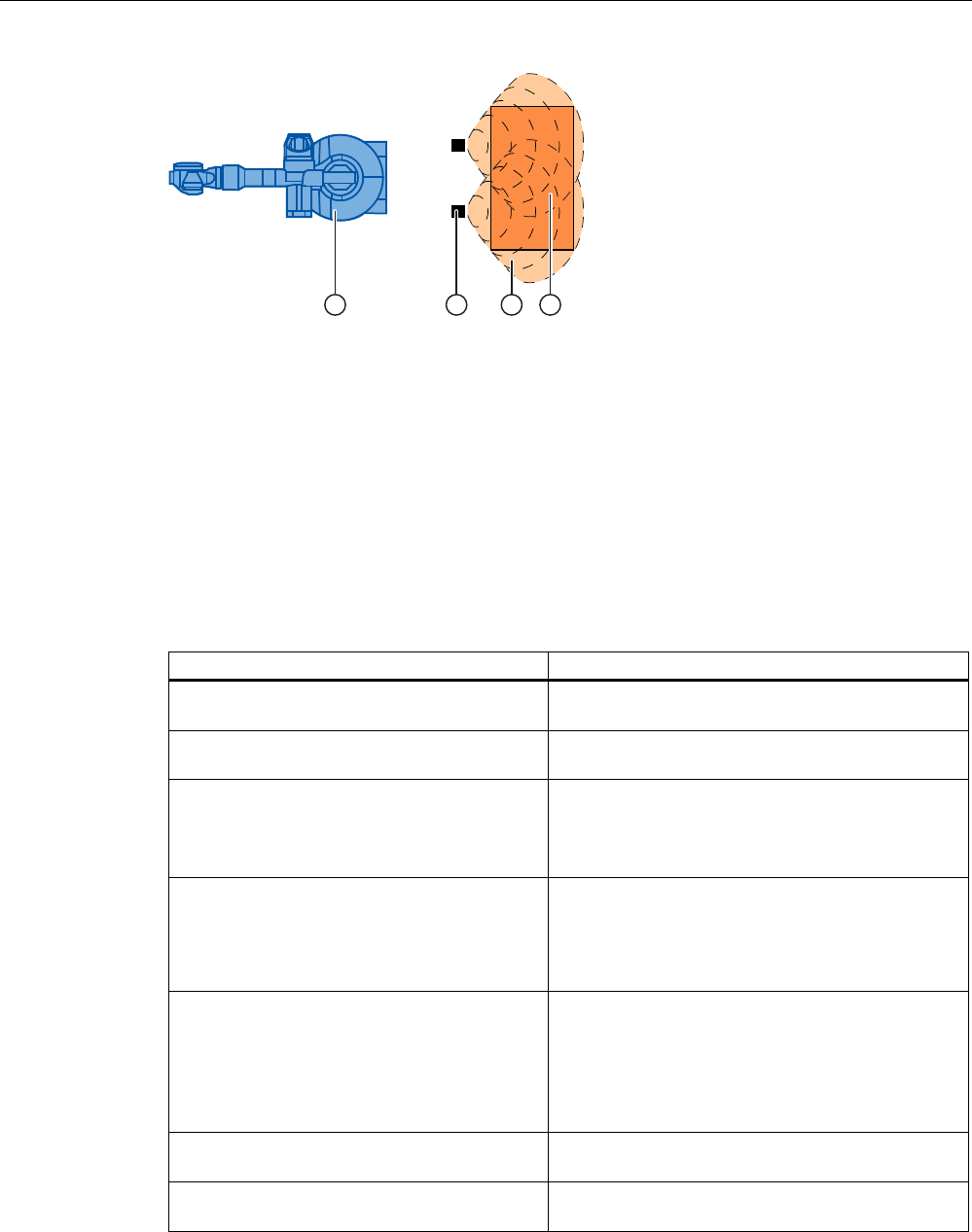
Planning application
3.6 Effective ranges and zones
Mobile Panel 277F IWLAN
Operating Instructions, 12/2007, A5E01003940-01 63
① Machine that will be operated from within the effective range
② Transponder with transmitting range in the form of a lobe
③ Planned effective range;
Assuming that the Mobile Panel is aligned with the effective range, fail-safe operation of the
machine is possible.
④ Actual effective range, safe operation is still possible from here.
Rules for effective ranges
The following rules apply when defining effective ranges:
Rule Explanation
The distance between the transponder and the
HMI device must not be longer than 8m.
System limits
The effective range must be sized in such a
way that it can be fully seen by the operator.
Too great or an unclear effective range prevents
visual control on the part of the operator.
The distance between the machine to be
operated and the operator must be sized
depending on the machine.
Insufficient distance from the machine increases the
injury hazard for the user.
Too great a distance from the machine prevents
visual control on the part of the operator.
Machine, transponder and operator position
must be aligned with each other.
The HMI device must be able to measure the
distance to the transponder during operation. To do
this, you have to align the HMI device with the
transponder. The operator must be able to see the
the machine at the same time.
Effective ranges should not overlap.
Consequently you should only assign each
transponder to a single effective range.
Transponders in different effective ranges
must be far enough away from each other that
their transmission ranges do not overlap.
Assignment of effective range to the machine that
will be operated must be unique.
You can set up a maximum of 127 effective
ranges in a project.
System limits
A maximum of 127 transponders can be
assigned to one effective range.
System limits

Planning application
3.6 Effective ranges and zones
Mobile Panel 277F IWLAN
64 Operating Instructions, 12/2007, A5E01003940-01
Procedure
1. On the system plan specify which parts of the system will be operated with the enabling
buttons. You require effective ranges for these areas of the system.
2. Specify the spatial expansion of the individual effective ranges. The operator must be
located within the limits of the respective effective range in order to operate the
corresponding plant unit with the enabling buttons.
Comply with the rules for the definition of effective ranges. Take special note that the
effective range is not too large so that it cannot be seen or that any other hazards occur.
3. Plan the transponders in the effective range in such a manner that the effective range is
covered by the radiated emission of the transponders. Also note that the effective range
is not too large so that it cannot be seen or that any other hazards occur.
4. Define:
– A name, a display name and an ID from the value range 1 to 65534 for each effective
range
– A name and a plant-unique ID for each transponder from the value range 1 to 65534
– For each effective range the maximum distance that the HMI device can have to the
transponders of this effective range. The distance must be the same for all
transponders of an effective range.
– The mounting location for an indicator, for example a light that shows that an HMI
device is logged in in the effective range.
5. On the system plan, note the display names and the IDs that you use during
commissioning.
Prior to commissioning you must affix the IDs of the effective ranges in the plant so that
they are easily legible.

Mobile Panel 277F IWLAN
Operating Instructions, 12/2007, A5E01003940-01 65
Installation and connection 4
4.1 Checking the package contents
Check the package contents for visible signs of transport damage and for completeness.
NOTICE
Do not install parts damaged during shipment. In the case of damaged parts, contact your
Siemens representative.
The documentation belongs to the HMI device and is required for subsequent
commissioning. Keep the supplied documentation to hand throughout the entire service life
of the HMI device. You must pass on the enclosed documentation to any subsequent owner
or user of the HMI device. Make sure that every supplement to the documentation that you
receive is stored together with the operating instructions.
The following is supplied along with the HMI device:
● HMI device
● Main battery
● Bridging battery
● Function manual "Fail-safe operation of the Mobile Panel 277F IWLAN", in German
● CD
The CD includes:
– Function manual "Fail-safe operation of the Mobile Panel 277F IWLAN", in German,
English and Japanese
– F-FBs for the Mobile Panel 277F IWLAN
● Cover cap with rubber seal
● Screws for fixing the cover cap
● Label for cover cap
Additional documents may be included in the delivery.

Installation and connection
4.2 Mounting the charging station
Mobile Panel 277F IWLAN
66 Operating Instructions, 12/2007, A5E01003940-01
4.2 Mounting the charging station
Requirements
● 4 x M6 cylinder head screws, with nuts if required
● You have selected a location with a low ambient temperature
To charge the batteries, the ambient temperature / battery temperature must not exceed
40 °C
● You have selected a position for the charging station that is easy and safe to reach
● You have selected a good ergonomic height for the charging station
Procedure
Proceed as follows:
1. Place the charging station from the front onto the mounting surface.
2. Mark the fastening holes with a marking-off tool.
3. Drill 4 through holes or 4 x M6 threaded holes.
4. Mount the charging station.
Result
The charging station is now mounted.
See also
Mounting location and clearance of charging station (Page 54)
Application and ambient conditions (Page 51)
4.3 Setting transponder ID and inserting the battery
Introduction
To operate the transponder you must first insert the batteries and set the transponder ID.
The transponder ID is read and evaluated by the HMI device in the current project.
Requirements
● Torx screwdriver, size T10
● Screwdriver, size 0
● 3 AA mignon batteries, 1.5 V, included in delivery
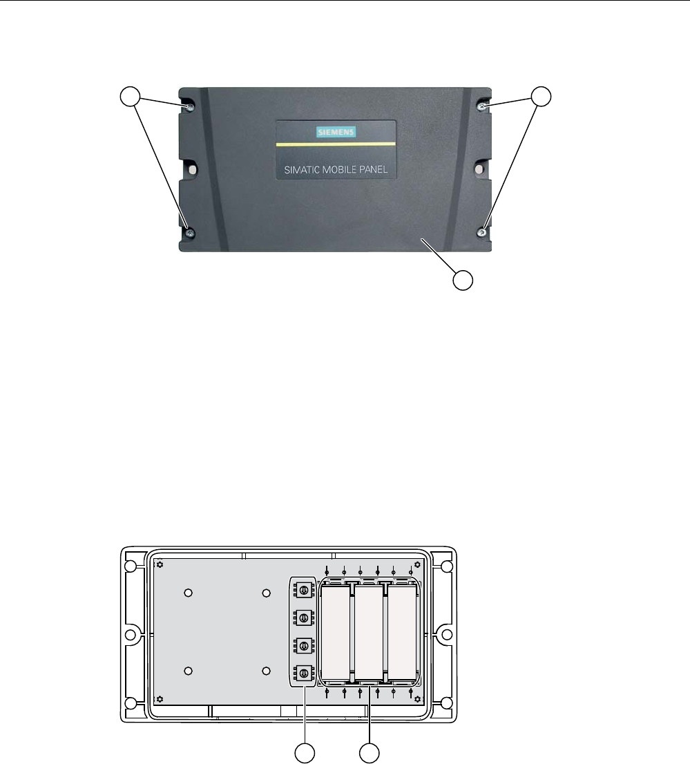
Installation and connection
4.3 Setting transponder ID and inserting the battery
Mobile Panel 277F IWLAN
Operating Instructions, 12/2007, A5E01003940-01 67
Procedure for opening the transponder
① Screws
② Cover
1. Loosen the four marked screws.
2. Lay the cover aside.
The cover is designed in such a way that the screws cannot be lost.
Rotary coding switch and batteries
The following figure shows the position of the 4 rotary coding switches and the batteries in
the transponder.
① Rotary coding switch
② Batteries
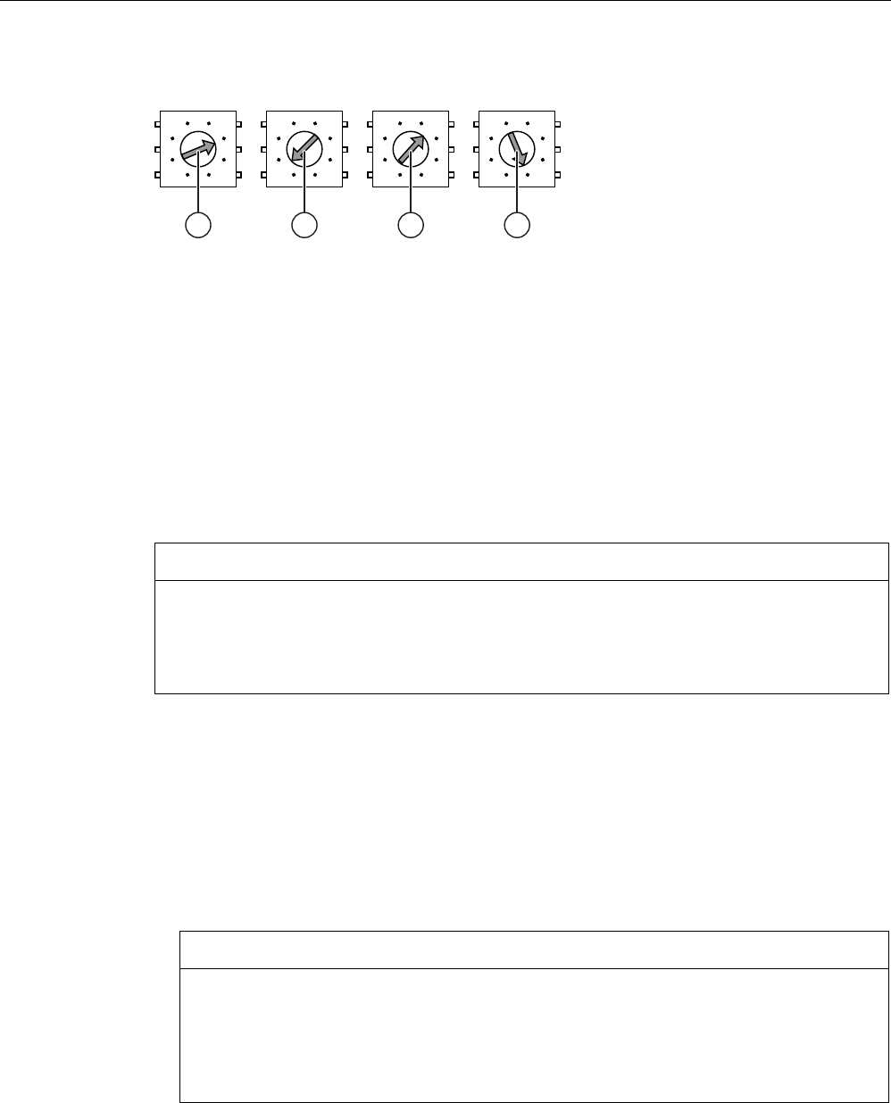
Installation and connection
4.3 Setting transponder ID and inserting the battery
Mobile Panel 277F IWLAN
68 Operating Instructions, 12/2007, A5E01003940-01
Example for setting the transponder ID
$
&
(
$
&
(
$
&
(
$
&
(
① Rotary coding switches for 4th decade,
MSB: most significant byte
Set value: 3
② Rotary coding switches for 3rd decade Set value: A
③ Rotary coding switches for 2nd decade Set value: 2
④ Rotary coding switches for 1st decade,
LSB: least significant byte
Set value: 7
The figure shows the set transponder ID 3A27H, i.e. 14,887, in decimal format.
Procedure
CAUTION
ESD
When working in the open housing, ensure that current-carrying conductors do not come
into contact with electrical circuits.
Note the ESD instructions.
Proceed as follows:
1. Insert the batteries as shown on the printed circuit board.
2. Set the transponder ID with the help of a screwdriver.
Please note the MSB and LSB markings on the printed circuit board.
Set the hexadecimal transponder ID. The values permitted in hexadecimal format are 1 to
FFFE, i.e. decimal format from 1 to 65,534.
3. Screw down the cover on the transponder.
NOTICE
Damage to thread
The transponder housing is made of plastic. Therefore, the mounting hole threads
cannot handle the same amount of stress as a comparable metallic housing. If the
screws are tightened more than 20 times, there is risk of damage to the threads.
Only tighten the screws with the permitted torque of 0.4–0.5 Nm.

Installation and connection
4.4 Mounting the transponder
Mobile Panel 277F IWLAN
Operating Instructions, 12/2007, A5E01003940-01 69
Result
The batteries have been inserted in the transponder. The transponder ID is now set.
See also
Distance measurement between HMI device and transponder (Page 61)
4.4 Mounting the transponder
Requirements
● 2 x M4 cylinder head screws, with nuts if required
● The batteries have been fitted in the transponder and the ID is set
● You have selected a position that provides good illumination for the desired area
The transmitting range of the transponder and the receiving area of the HMI device
approximate to a lobe shape with a range of approximately 8 m. More information can be
found in chapter Radiation characteristic (Page 314) .
Procedure
Proceed as follows:
1. Place the transponder from the front onto the mounting surface.
2. Mark the fastening holes with a marking-off tool.
3. Drill two through holes or two threaded holes M4.
4. Attach the transponder.
Result
The transponder is now mounted.
4.5 Electrical installation
Electrical connections
The following connection options are available:
HMI device Charging station Tabletop power supply
unit
Configuring PC Yes
Supply voltage Yes Yes
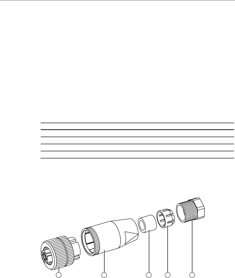
Installation and connection
4.6 Connection of the charging station to the power supply
Mobile Panel 277F IWLAN
70 Operating Instructions, 12/2007, A5E01003940-01
4.6 Connection of the charging station to the power supply
Requirements
● The charging station is mounted according to the specifications in this document.
● Cable plug included in the scope of supply
● Three-core cable, flexible, 0.75 mm²
● End sleeves
Pin assignment
Pin Assignment
1 +24 VDC
2 n. c.
3 GND 24 V
4 PE
Procedure for mounting the cable plug
1. Screw the cables to the contacts in the socket insert and mount the socket.
The following figure shows an exploded view of the cable plug:
① Socket insert
② Coupling bush
③ Seal

Installation and connection
4.7 Connecting the HMI device
Mobile Panel 277F IWLAN
Operating Instructions, 12/2007, A5E01003940-01 71
④ Fastening case
⑤ Cable seal
Procedure for connecting the charging station
1. Connect the supply line to the power supply.
2. Connect the cable plug to the counterpart on the charging station.
Result
The charging station is now connected to the power supply. The "POWER" LED lights up
green when the power supply to the charging station is within the nominal range.
See also
Rated voltages (Page 57)
4.7 Connecting the HMI device
4.7.1 Opening and closing the terminal compartment
Introduction
You can open the connection bay of the HMI device during operation.
Before you begin:
CAUTION
Malfunctions
If the HMI device is switched on and resting on its front, the following can be activated:
• The emergency stop button
This can bring the system to a standstill unintentionally.
• The key-operated switch or an illuminated pushbutton
This can result in malfunctions.
NOTICE
Damage to the HMI device
Pay attention to cleanliness. Foreign bodies or liquids must not come into contact with the
printed circuit board or penetrate the inside of the HMI device.
Place the HMI device with the front side facing down on a flat, clean surface to protect
against damage.
Installation and connection
4.7 Connecting the HMI device
Mobile Panel 277F IWLAN
72 Operating Instructions, 12/2007, A5E01003940-01
CAUTION
Shutdown or rampdown of the system
When you open the connection bay, you remove the main battery. This failure of the main
battery is bridged by the bridge battery, if fitted. The maximum buffer time is 5 minutes. If
you exceed the buffer time, the HMI device will switch off. If the HMI device has been
integrated, this will lead to a shutdown or rampdown of the system.
Do not exceed the buffer time!
Requirements
Cross-head screwdriver, size 2
Battery compartment and connection bay
① Locking latch
② Connection bay cover
③ Connection for tabletop power supply unit
④ Battery compartment cover
⑤ Charging contacts for charging station
⑥ USB interface
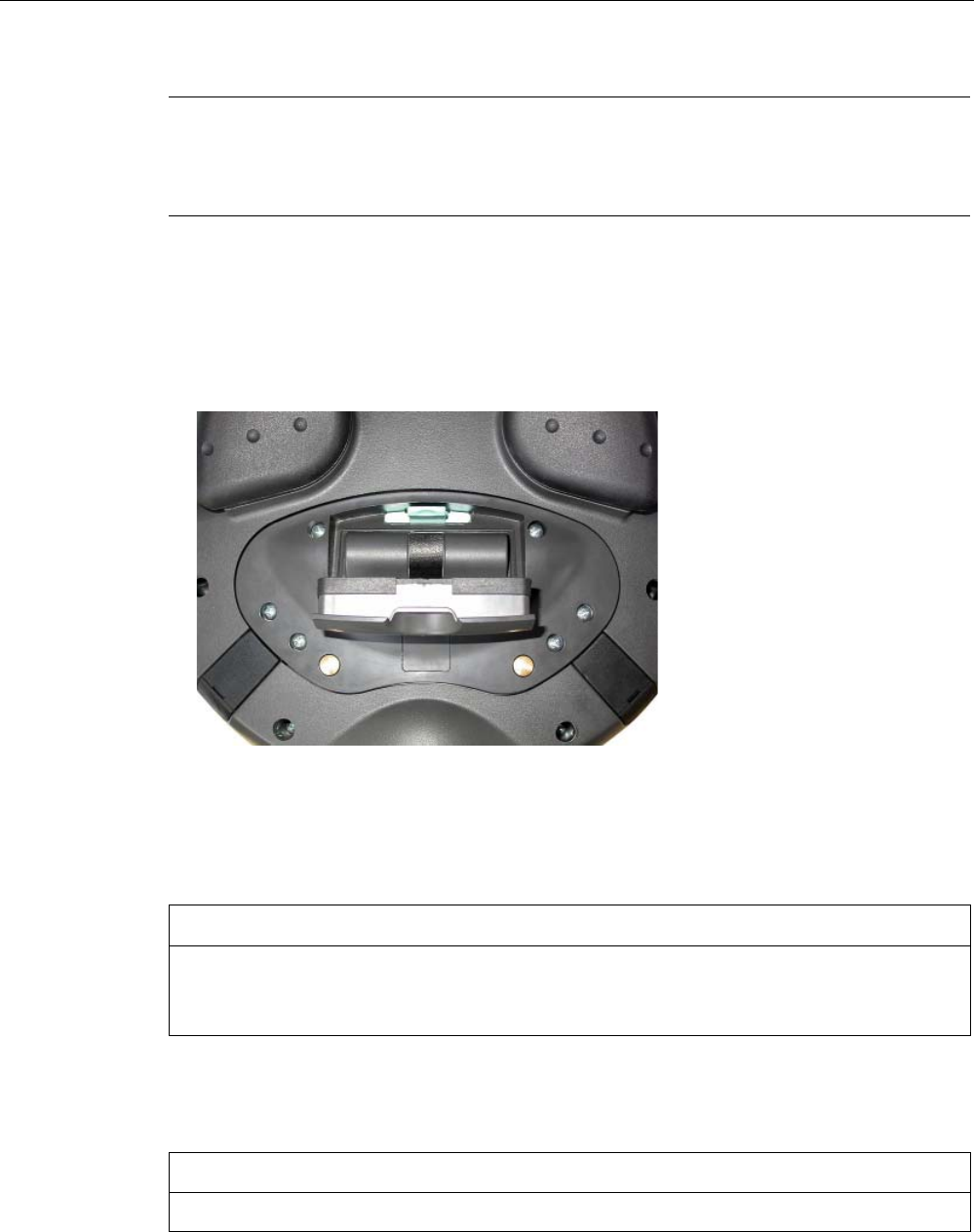
Installation and connection
4.7 Connecting the HMI device
Mobile Panel 277F IWLAN
Operating Instructions, 12/2007, A5E01003940-01 73
Note
Sequence for opening
Always remove the battery compartment cover first and remove the main battery before
opening the connection bay cover.
Procedure for opening the battery compartment
Proceed as follows:
1. Pull up the locking latch on the battery compartment cover.
The battery compartment cover can now be opened.
2. Remove the battery compartment cover.
Result
The battery compartment is open. The main battery, if fitted, is visible.
NOTICE
Damage to the HMI device
The connection bay cover is connected to the HMI device's housing by wiring. Close the
connection bay cover carefully.
Procedure for opening the connection bay
CAUTION
The connection bay may only be opened by trained skilled personnel for service purposes.

Installation and connection
4.7 Connecting the HMI device
Mobile Panel 277F IWLAN
74 Operating Instructions, 12/2007, A5E01003940-01
CAUTION
Damage to the HMI device
When the connection bay is open the HMI device is vulnerable to damage from mechanical
influences and live parts. If a bridging battery is fitted in the HMI device or the tabletop
power supply unit is connected, some parts of the HMI device will still be electrically live.
Please observe the following:
If you have connected a tabletop power supply unit, isolate the unit from the HMI device if
possible.
CAUTION
Damage to the HMI device
When the connection bay is open the HMI device is vulnerable to damage from electrostatic
discharge.
ESD
When working in the open housing, ensure that current-carrying conductors do not come
into contact with electrical circuits.
Note the ESD instructions.
1. Remove the main battery (if fitted) using the ribbon.
The bridging battery and the memory card, if fitted, are now visible.
2. Unscrew the six screws approximately 1 cm out of the cover.
The cover is designed in such a way that the screws cannot be lost.
3. Open the cover.
Result
The connection bay is open.
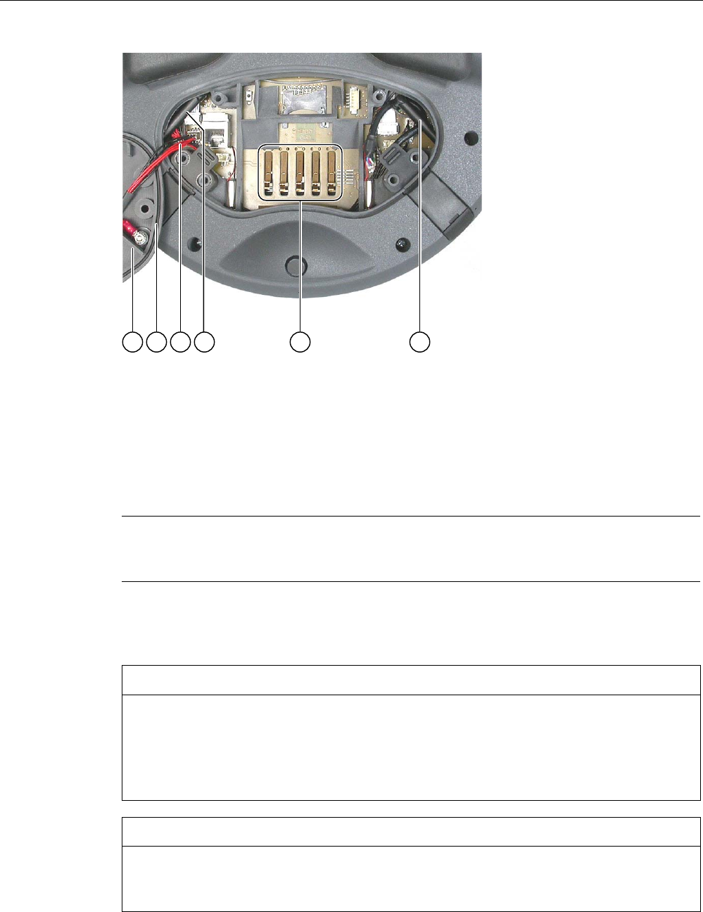
Installation and connection
4.7 Connecting the HMI device
Mobile Panel 277F IWLAN
Operating Instructions, 12/2007, A5E01003940-01 75
① Connection bay cover
② Rubber seal
③ Wiring to charging contacts
④ Antenna
⑤ Contacts for main battery
Note
Only use the connection bay to insert the memory card and bridging battery! Do not insert
any other objects in the connection bay.
Notes for closing
CAUTION
Damage to thread
The HMI device housing is made of plastic. Therefore, the mounting hole threads cannot
handle the same amount of stress as a comparable metallic housing. If the screws are
tightened more than 20 times, there is risk of damage to the threads.
Do not exceed 0.4 to 0.5 Nm of torque when tightening the screws.
NOTICE
Damage to wiring at charging contacts
When closing the connection bay cover, be careful not to trap the wiring at the charging
contacts.
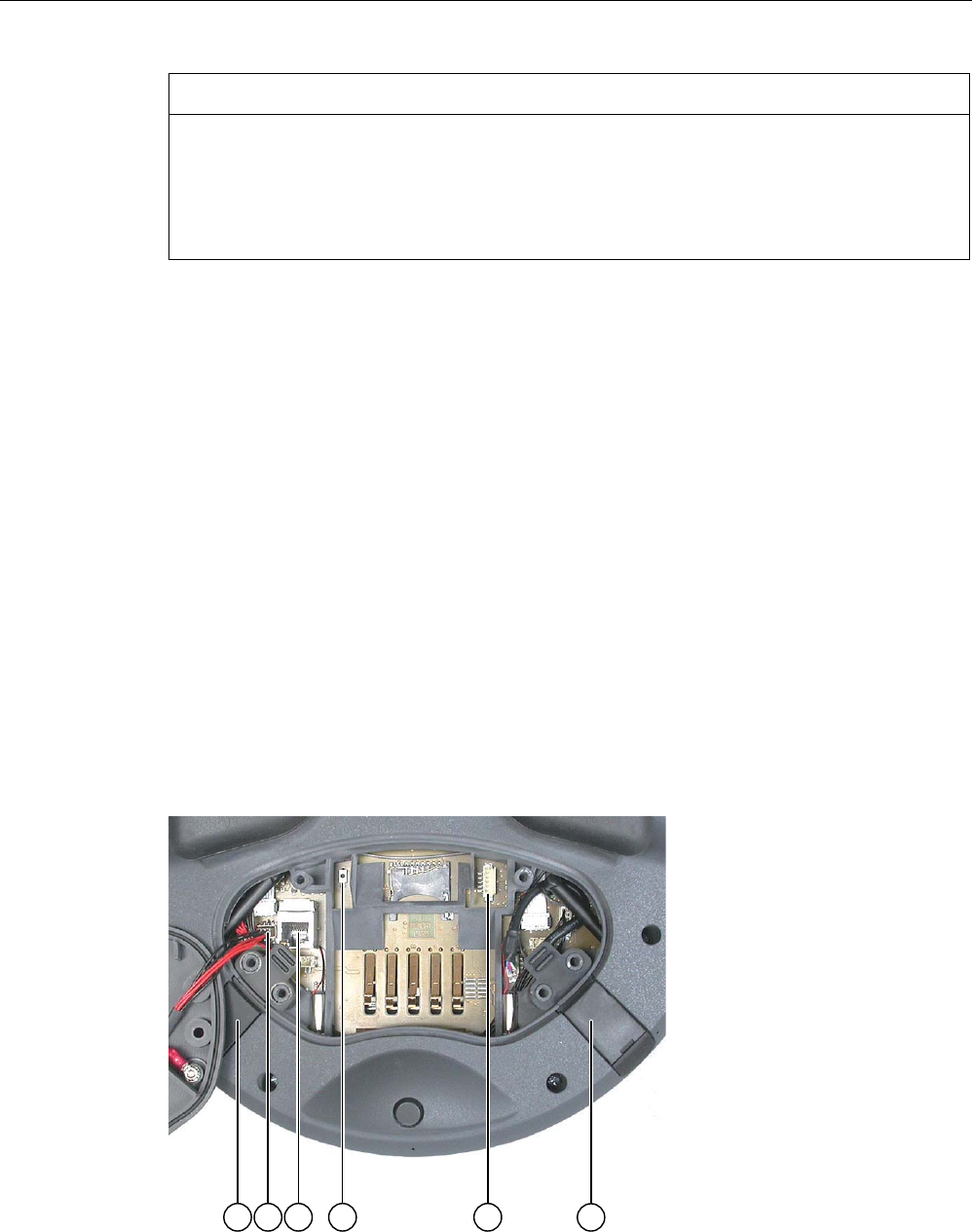
Installation and connection
4.7 Connecting the HMI device
Mobile Panel 277F IWLAN
76 Operating Instructions, 12/2007, A5E01003940-01
CAUTION
IP65 degree of protection not fulfilled
Ensure that the seals belonging to the connection bay cover and battery compartment
cover are present during mounting.
After completing the connections, check whether the covers are fitted on the USB interface
and the terminal for the tabletop power supply unit.
Procedure for closing the connection bay and battery compartment
1. Place the cover on the connection bay.
Be careful with the wiring to the charging contacts.
2. Tighten the 6 cover screws.
3. Insert the main battery.
4. Replace the cover on the battery compartment.
The fastener of the battery compartment cover must engage below the locking latch.
Result
The connection bay and battery compartment of the HMI device are now closed.
4.7.2 Interfaces of the HMI device
The following figure shows the interfaces of the HMI device.

Installation and connection
4.7 Connecting the HMI device
Mobile Panel 277F IWLAN
Operating Instructions, 12/2007, A5E01003940-01 77
① Connection for tabletop power supply unit
② Cable connector for wiring to charging contacts
③ RJ45 jack for PROFINET
④ Reset button
⑤ Connection for bridging battery
⑥ USB interface
CAUTION
Degree of protection IP 65 not fulfilled
If you want to use the RJ45 interface, you must first open the connection bay. If the
connection bay is open, degree of protection IP 65 is not fulfilled.
Only use the RJ45 jack for the connector of the configuring PC when resetting to factory
settings.
CAUTION
Shutdown or rampdown of the system
Triggering the reset button results in the following:
• The HMI device switching off and restarting
• If the HMI device has been integrated, the F-CPU triggers a local shutdown or a global
rampdown.
Only press the reset button in an emergency.
USB jack and connector for tabletop power supply unit
The USB jack and the connector for the tabletop power supply unit are shown as plugs.
See also
Description of interfaces on the HMI device (Page 313)
4.7.3 Connecting the configuring PC
Requirements
● For connection via PROFINET (LAN via RJ 45 interface):
The connection bay on the HMI device is open.
● For connection via PROFINET (WLAN):
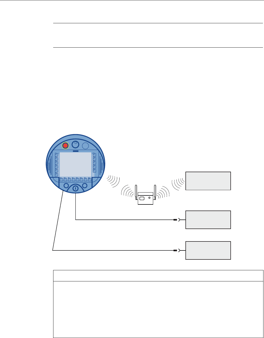
Installation and connection
4.7 Connecting the HMI device
Mobile Panel 277F IWLAN
78 Operating Instructions, 12/2007, A5E01003940-01
Note
You must connect the HMI device to the configuring PC in infrastructure mode. An ad hoc
network is not possible.
The HMI device must be in an area with sufficient WLAN quality. It must be possible for
the configuring PC to be contacted via WLAN.
Connection graphic
The following figure illustrates the connection between the HMI device and the configuring
PC. You can transfer the following data between the HMI device and a configuring PC:
● Project
● HMI device image
● Additional project data
3&
3&
86% 3&
352),1(7
NOTICE
USB connection sequence
Observe the following sequence when connecting by USB:
1. HMI device
2. PC
USB Host-to-Host cable
Only use the driver for the USB host cable, which is included in the WinCC flexible
package. Never use the driver supplied with the USB Host-to-Host cable.

Installation and connection
4.7 Connecting the HMI device
Mobile Panel 277F IWLAN
Operating Instructions, 12/2007, A5E01003940-01 79
Restoring factory settings
Note
To update the operating system and reset to factory settings, you must connect the HMI
device to the configuring PC via the RJ45 interface.
Note
For a point-to-point connection, use a cross cable. The HMI device and the PC can also be
part of a LAN network.
CAUTION
Degree of protection IP 65 not fulfilled
If you connect the configuring PC directly to the HMI device through the RJ45 interface, you
must open the connection bay. If the connection bay is open, degree of protection IP 65 is
not fulfilled.
NOTICE
Damage to the HMI device
Pay attention to cleanliness. Foreign bodies or liquids must not come into contact with the
printed circuit board or penetrate the inside of the HMI device.
Only connect a configuring PC directly to the HMI device for a short period.
The ports are described in the specifications.
See also
Interfaces of the HMI device (Page 76)
4.7.4 Connecting the PLC
Introduction
Only use approved components to connect a SIMATIC S7 PLC. You can find more
information about this on the Internet at:http://mall.automation.siemens.com.
Note
A SIMATIC S7F is vital for fail-safe functionality. The HMI device cannot be operated without
fail-safe communication.
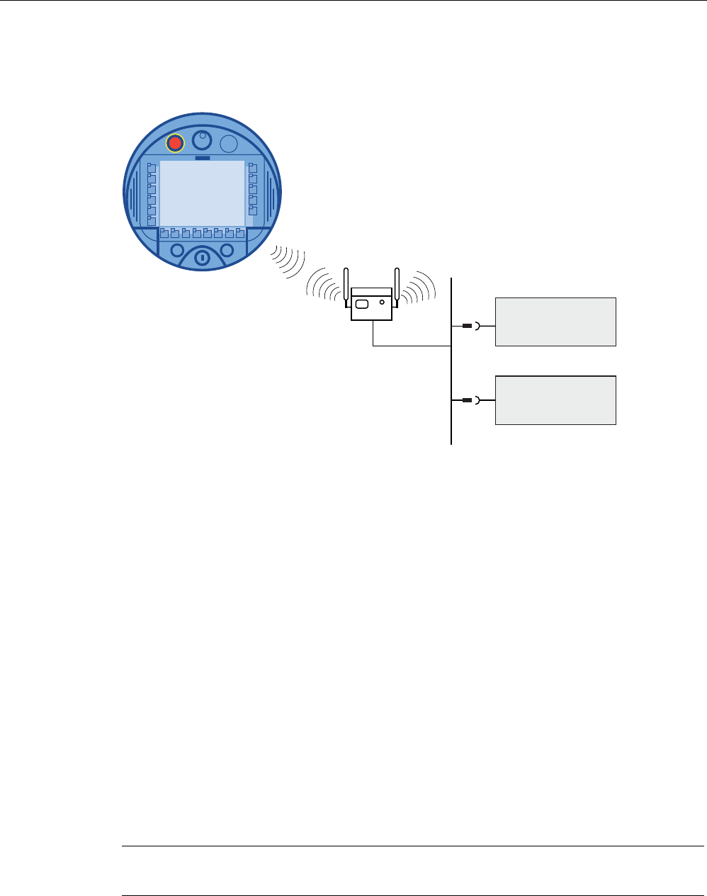
Installation and connection
4.7 Connecting the HMI device
Mobile Panel 277F IWLAN
80 Operating Instructions, 12/2007, A5E01003940-01
Connection graphic
The following figure shows the connection between the PLC and the HMI device.
352),1(7
6,0$7,&6)
6,0$7,&6
See also
Interfaces of the HMI device (Page 76)
Communication (Page 32)
4.7.5 Connecting the printer
Introduction
Printers are connected to the HMI device via WLAN.
The current list of recommended printers for the HMI devices can be found on the Internet
under http://support.automation.siemens.com/WW/view/de/11376409.
Observe the supplied printer documentation when you connect the printer.
Connection graphic
Note
It is not possible to connect a printer to the HMI device's USB interface.
The following figure illustrates the connection between the HMI device and a printer.
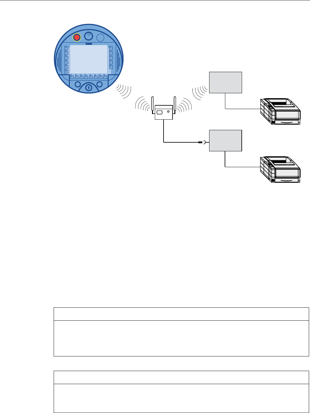
Installation and connection
4.7 Connecting the HMI device
Mobile Panel 277F IWLAN
Operating Instructions, 12/2007, A5E01003940-01 81
352),1(7
3&
3&
4.7.6 Connecting USB devices
The following devices can be connected to the USB port of the HMI device:
● External mouse
● External keyboard
● USB memory stick
Note when connecting
NOTICE
Devices with a separate power supply
Except for the configuring PC or PC, do not connect any device with a separate power
supply to the USB interface. You can connect the configuring PC or PC to the USB
interface for transferring, saving and restoring data.
NOTICE
Additional load for battery
Devices without a separate power supply cause additional load on the battery when they
are connected to the USB interface. This will reduce the battery's operation time.

Installation and connection
4.7 Connecting the HMI device
Mobile Panel 277F IWLAN
82 Operating Instructions, 12/2007, A5E01003940-01
NOTICE
Functional problem
If USB devices overload the interface, malfunctions might occur.
Observe the values for the maximum load of the USB interface. You will find the values in
the technical specifications.
NOTICE
Access to USB interface is not possible
The USB interface is disabled while the main battery is being changed. During a main
battery change it is not possible to export recipes and archives to a USB memory stick, for
example.
Make sure no one tries to access the USB interface while the main battery is being
changed.
See also
Interfaces of the HMI device (Page 76)
4.7.7 Connecting the tabletop power supply unit
Introduction
The tabletop power supply unit is used to power the HMI device and to charge the battery in
the HMI device in 120 V and 230 V networks. The setting of the voltage range takes place
automatically. The tabletop power supply unit is connected with the power supply cable by
the input connector.
CAUTION
Danger of overheating
Do not cover the tabletop power supply unit.
CAUTION
Please note that the mains connector must be removed for a complete disconnection from
the mains.
NOTICE
Only use the tabletop power supply unit approved for the HMI device. The tabletop power
supply unit is only suitable for an office environment.
Installation and connection
4.8 Inserting, charging and changing the battery
Mobile Panel 277F IWLAN
Operating Instructions, 12/2007, A5E01003940-01 83
The tabletop power supply unit is supplied with power supply cables for the following
countries:
● UK
● US
● EU
● Japan
Procedure
1. Remove the cover from the plug of the HMI device.
2. Connect the tabletop power supply unit to the HMI device.
3. Connect the tabletop power supply unit to the mains with the correct power supply cable.
See also
Rated voltages (Page 57)
4.8 Inserting, charging and changing the battery
4.8.1 Safety instructions
CAUTION
Charging and discharging the battery
In the following cases, there is a risk of fire and, in extreme cases, explosion!
• Incorrect charging and discharging of the battery
• Reverse polarity
• Short-circuit
Only charge the bridging battery in the HMI device.
Only charge the main battery in the HMI device or in the charging compartment of the
charging station.
CAUTION
Danger of injury
If used incorrectly, fluid can leak from the battery. Avoid contact with the battery fluid. If fluid
comes into contact with the skin, rinse with water.
If fluid comes into contact with the eyes, rinse with water and seek medical advice.

Installation and connection
4.8 Inserting, charging and changing the battery
Mobile Panel 277F IWLAN
84 Operating Instructions, 12/2007, A5E01003940-01
CAUTION
The battery is a lithium ion battery. The following safety notes apply to these rechargeable
batteries:
• Do not crush
• Do not expose to heat and do not burn
• Do not short-circuit
• Do not take apart
• Do not submerge in liquids - the battery could crack or explode.
• Store unused batteries away from the following items, which can cause the contacts to
be bridged.
– Paper clips
– Coins
– Keys
– Nails
– Screws or other small metal objects
CAUTION
Possibility of rampdown while logging onto effective range
If the HMI device no longer recognizes the transponder and, therefore, the measuring
range, it triggers a rampdown.
To change the battery, rest the HMI device on its front. Align the HMI device so that it is still
possible to measure the distance between the HMI device and the transponder.
If possible, log the HMI device off from the effective range.
CAUTION
Malfunctions
If the HMI device is resting on its front, the following can be activated:
• The emergency stop button
This can bring the system to a standstill unintentionally.
• The key-operated switch or an illuminated pushbutton
This can result in malfunctions.
ESD
When working in the open housing, ensure that current-carrying conductors do not come
into contact with electrical circuits.
Note the ESD instructions.
NOTICE
Only use batteries that are approved for the HMI device.

Installation and connection
4.8 Inserting, charging and changing the battery
Mobile Panel 277F IWLAN
Operating Instructions, 12/2007, A5E01003940-01 85
NOTICE
Pay attention to cleanliness. Foreign bodies or liquids must not come into contact with the
printed circuit board or penetrate the inside of the HMI device.
Place the HMI device with the front side facing down on a flat, clean surface to protect
against damage.
Disposal
Used lithium ion batteries are special waste. Please dispose of used lithium ion batteries
properly according to the appropriate regulations. Label transport packaging with the words:
"USED LITHIUM BATTERIES".
See also
Distance measurement between HMI device and transponder (Page 61)
4.8.2 Inserting batteries for the first time
NOTICE
To charge the batteries, the ambient temperature / battery temperature must not exceed
40 °C The higher the temperature, the longer it will take for the battery to charge.
Find a place with a cool ambient temperature for the charging station. If necessary, allow
the battery to cool first.
The batteries are delivered uncharged.
Please note that a battery is subject to a natural self-discharge. The self-discharge can lead
to a complete discharge over long periods of disuse.
Requirements for inserting the bridging battery
You have opened the battery compartment and connection compartment of the HMI device.
Procedure for inserting the bridging battery
Observe the safety information!
Proceed as follows:
1. Plug the bridging battery's plug connector into the interface in the connection
compartment.
The plug connector is coded. There is no risk of incorrect connection.
2. Insert the bridging battery.
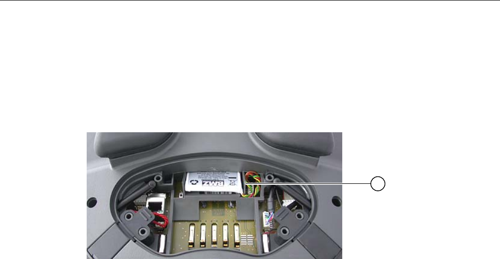
Installation and connection
4.8 Inserting, charging and changing the battery
Mobile Panel 277F IWLAN
86 Operating Instructions, 12/2007, A5E01003940-01
3. Align the line as shown in the figure. Ensure that the line runs underneath the cable entry.
Result
The bridging battery is now fitted.
The following figure shows the bridging battery inserted in the connection compartment.
① Cable routing
Requirements for inserting the main battery
The connection compartment is open.
The battery compartment is open.
Procedure for inserting the main battery
1. Place the main battery in the battery compartment.
2. Close the battery compartment.
Result
The main battery is inserted.
The following figure shows the main battery in the battery compartment.
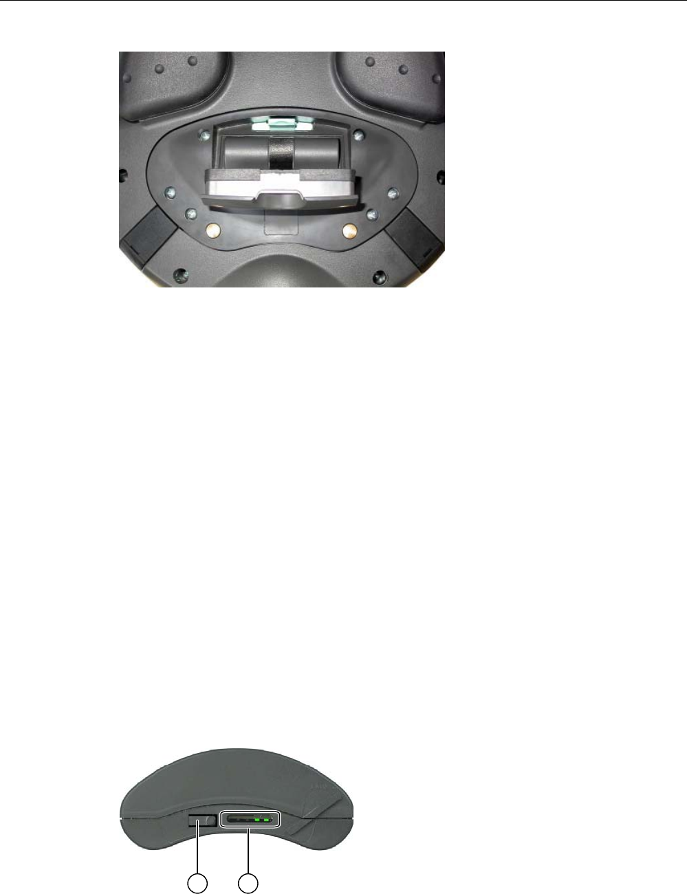
Installation and connection
4.8 Inserting, charging and changing the battery
Mobile Panel 277F IWLAN
Operating Instructions, 12/2007, A5E01003940-01 87
Charging the battery
The batteries are charged automatically whenever the HMI device is placed in the charging
station or connected to the tabletop power supply unit.
See also
Safety instructions (Page 83)
4.8.3 Displaying battery status
The battery's charging condition can be displayed in the following ways:
● On the main battery itself
● By the BAT LED on the HMI device
● In the "OP" dialog box, "Battery" tab in the Control Panel
● In a running project, if configured
Procedure for displaying the charging condition on the main battery itself
The LED display on the main battery consists of 5 LEDs.

Installation and connection
4.8 Inserting, charging and changing the battery
Mobile Panel 277F IWLAN
88 Operating Instructions, 12/2007, A5E01003940-01
① Pushbutton
② LED display
Briefly press the pushbutton on the battery.
The LEDs on the LED display will briefly light up to show the charging condition. The LEDs
will light up according to the charging status. If all the LEDs light up, the battery is fully
charged. If no LEDs light up, the battery is flat.
4.8.4 Changing the main battery
Introduction
CAUTION
Shutdown or global rampdown
If the bridging battery can no longer be charged, the HMI device will switch off the next time
the main battery is changed.
Change the bridging battery at least every 5 years.
Note
Change the main battery in good time!
We recommend that you replace the battery when it can only be charged to 50%. This is the
case after approximately 500 complete charging cycles.
A charging cycle is complete when the battery is fully charged.
Example:
The battery has a charging condition of 80%. It needs another 20% before it is fully charged.
The battery is charged. This charging process counts as one fifth of a complete charging
cycle.
We recommend keeping an inventory of spare main batteries.
You can replace the main battery during operation. The bridging battery supplies power to
the HMI device while the main battery is being changed. The maximum buffer time is 5
minutes.
While the power is being drawn from the bridging battery, the following features are
deactivated:
● Display backlighting
● The function keys and associated LEDs
● All LEDs except for "SAFE" and "RNG"
● The illuminated pushbuttons and handwheel
● USB interface

Installation and connection
4.8 Inserting, charging and changing the battery
Mobile Panel 277F IWLAN
Operating Instructions, 12/2007, A5E01003940-01 89
NOTICE
Access to USB interface is not possible
The USB interface is deactivated while the main battery is changed. Make sure no one
tries to access the USB interface while the main battery is being changed.
Requirements
You have opened the battery compartment of the HMI device
Procedure
Observe the safety information.
Proceed as follows:
1. If the HMI device is logged onto the effective range, log it off.
2. Remove the main battery using the ribbon.
3. Insert the new main battery.
4. Close the battery compartment.
Result
The main battery has been changed.
Disposal
Used lithium ion batteries are special waste. Please dispose of used lithium ion batteries
properly according to the appropriate regulations. Label transport packaging with the words:
"USED LITHIUM BATTERIES".
See also
Safety instructions (Page 83)
Power management (Page 98)
4.8.5 Changing the bridging battery
Introduction
The bridging battery is charged automatically in the following cases:
● The HMI device is placed in the charging station
● The main battery in the HMI device is sufficiently charged
● The HMI device is connected to the tabletop power supply unit

Installation and connection
4.8 Inserting, charging and changing the battery
Mobile Panel 277F IWLAN
90 Operating Instructions, 12/2007, A5E01003940-01
CAUTION
Shutdown or global rampdown
If the bridging battery can no longer be charged, the HMI device will switch off the next
time the main battery is changed.
Change the bridging battery at least every 5 years.
NOTICE
Bridging of main battery not possible
After the bridging battery is changed it must first be recharged before the main battery
can be bridged.
Do not change the main battery immediately after changing the bridging battery. Check
the charging status of the bridging battery first.
The "Battery" tab in the "OP" dialog box in the Control Panel displays the charging status
and temperature of the main battery and bridging battery.
Requirements
● The project on the HMI device is complete and the HMI device is switched off
● You have opened the battery compartment of the HMI device
Procedure
Observe the safety information!
Proceed as follows:
1. Remove the main battery using the ribbon.
2. Open the connection bay.
3. Disconnect the plug connector of the bridging battery.
4. Remove the bridging battery.
5. Plug the plug connector of the new bridging battery into the interface in the connection
bay.
The plug connector is coded. There is no risk of incorrect connection.
6. Insert the new bridging battery.
7. Align the lines.
8. Close the connection bay.
9. Insert the main battery.
10. Replace the cover on the battery compartment.
The fastener of the battery compartment cover must engage below the locking latch.

Installation and connection
4.9 Switching on and testing the HMI device
Mobile Panel 277F IWLAN
Operating Instructions, 12/2007, A5E01003940-01 91
Result
The bridging battery has been changed.
Disposal
Used lithium ion batteries are special waste. Please dispose of used lithium ion batteries
properly according to the appropriate regulations. Label transport packaging with the words:
"USED LITHIUM BATTERIES".
See also
Safety instructions (Page 83)
4.9 Switching on and testing the HMI device
Requirements
In order to switch on the Mobile Panel 277F IWLAN, one of the following requirements must
be met:
● The batteries have been charged and inserted in the HMI device
● The HMI device is placed in the charging station
● The HMI device is connected to the tabletop power supply unit
Procedure
Proceed as follows:
1. To switch the HMI device on, briefly press the ON/OFF button.
The "PWR" LED lights up.
The screen lights up. A progress bar is displayed during startup.
The Loader is displayed once the operating system has started. If a charged battery is
available, the "BAT" LED lights up green. If the HMI device does not start, the battery
may be empty or not available for use.
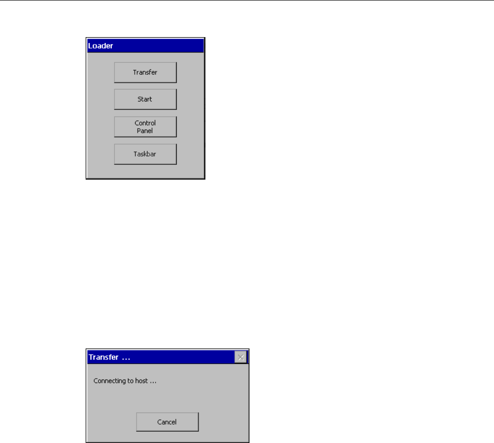
Installation and connection
4.9 Switching on and testing the HMI device
Mobile Panel 277F IWLAN
92 Operating Instructions, 12/2007, A5E01003940-01
Transfer
The HMI device automatically switches to "Transfer" mode if the following requirements have
been met:
● No project is loaded on the device
● At least one data channel has been configured
On first commissioning, there is no project on the HMI device and no data channel has
been parameterized.
While communication is being established, the following dialog box is displayed:
Press "Cancel" to stop the transfer.
Result
The Loader appears.

Installation and connection
4.9 Switching on and testing the HMI device
Mobile Panel 277F IWLAN
Operating Instructions, 12/2007, A5E01003940-01 93
Starting and transferring a project
Note
When restarting the system, a project may already be loaded on the HMI device. The project
will then start either following a delay (whose duration can be adjusted) or when you press
the "Start" button.
When the project starts, the following dialog boxes will appear:
• "Establishing secure connection"
• "Testing enabling button"
If you want to transfer another project, for example, proceed as follows:
• Close the project and restart the HMI device.
• If necessary, parameterize the required data channel.
• Select "Transfer" to start the transfer.
Function test
Check whether the HMI device is fully functional. The HMI device is fully functional when one
of the following states is indicated after switching on:
● The "Transfer" dialog is displayed.
● The Loader appears
● The "Test enabling button" dialog box appears.
Switching off the HMI device
To switch the HMI device off, press the ON/OFF button on the HMI device for at least 4
seconds.
If the project has been started, the "Confirm removal" dialog box appears following a prompt.
1. Press one of the enabling buttons to confirm the dialog box.
The HMI device is removed.
The current project is terminated.
The HMI device switches off.
See also
Inserting batteries for the first time (Page 85)
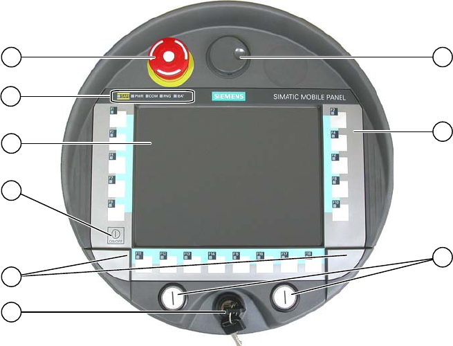
Mobile Panel 277F IWLAN
Operating Instructions, 12/2007, A5E01003940-01 95
Operator controls and displays 5
5.1 Overview
The following figure shows the operator controls and displays of the
Mobile Panel 277F IWLAN. This can vary, depending on the delivery condition of the HMI
device.
① Emergency stop button
② LED display
③ Display with touch screen
④ ON/OFF button
⑤ Covers for the labeling strip guides
⑥ Key-operated switch, optional
⑦ Illuminated pushbutton, optional
⑧ Membrane keyboard
⑨ Handwheel, optional

Operator controls and displays
5.2 Displays on the Mobile Panel 277F IWLAN
Mobile Panel 277F IWLAN
96 Operating Instructions, 12/2007, A5E01003940-01
Operator control functions
The functions assigned to the function keys, the handwheel, the key-operated switch and the
illuminated pushbuttons are determined during configuration. The above-mentioned operator
controls do not function outside of a project.
Evaluation and selection of the operator controls
The following information can be transferred between the HMI device and the PLC:
● Direction pulses of the handwheel
● Status of the function keys
● Status of the key-operated switch
● State of the illuminated pushbuttons
● State of the function keys and illuminated pushbutton LEDs
There are two ways of transmitting information:
● Direct keys
● System functions of WinCC flexible
Standard input unit
The standard input unit on the HMI device is the touch screen. All operating elements
required for touch operation are displayed on the touch screen once the HMI device has
started.
NOTICE
Damage to the touch screen
Never touch the touch screen with pointed or sharp objects. Avoid applying excessive
pressure to the touch screen with hard objects. Both these will substantially reduce the
useful life of the touch screen and even lead to total failure.
Always operate the HMI touch screen with your fingers or with a touch pen.
Damage to the keyboard
Pressing the keys with a hard instrument considerably reduces the service life of the key
mechanism.
Always use your fingers to operate the keys of your HMI device.
5.2 Displays on the Mobile Panel 277F IWLAN
Introduction
On the front of the Mobile Panel there are 5 LEDs that show the states of the HMI device
and communication.
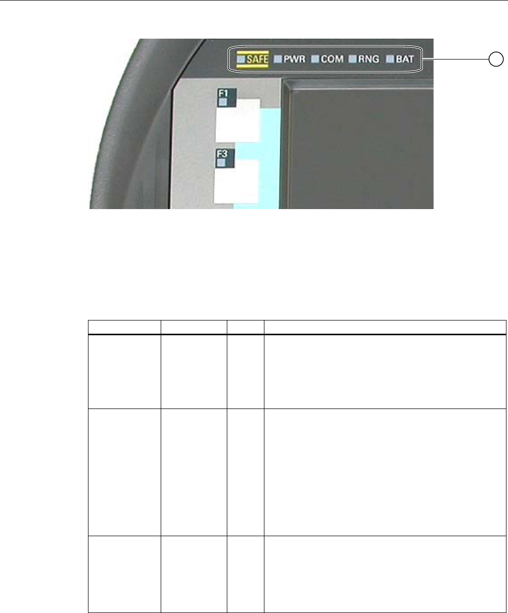
Operator controls and displays
5.2 Displays on the Mobile Panel 277F IWLAN
Mobile Panel 277F IWLAN
Operating Instructions, 12/2007, A5E01003940-01 97
① LED display
Meaning of the LED displays
The LEDs are only activated when the HMI device is switched on.
Functions Designation Color Meaning
PROFIsafe
communication
SAFE Yellow The "SAFE" LED lights up when the HMI device is
integrated in the safety program of the F CPU. The
requirement for this is that PROFIsafe communication
has been established.
If the "SAFE" LED lights up, the emergency stop button is
effective.
Power PWR Green The "PWR" LED only lights up or flashes when the HMI
device is switched on.
The "PWR" LED lights up under the following
circumstances:
• The battery is fitted and charged.
• The HMI device is in the charging station.
• The HMI device is connected to the tabletop power
supply unit
The "PWR" LED flashes when the HMI device is in the
"POWER SAVE 2" state.
Communication COM Green The "COM" LED remains off as long as no WLAN
network is configured.
The "COM" LED flashes when the HMI device is
attempting to establish a connection to a WLAN network.
The "COM" LED lights up when the HMI device has
established a connection to a WLAN network.

Operator controls and displays
5.3 Power management
Mobile Panel 277F IWLAN
98 Operating Instructions, 12/2007, A5E01003940-01
Functions Designation Color Meaning
Effective range RNG Green The "RNG" lights up when the HMI device is logged onto
the effective range.
If a communication error occurs after the HMI device has
logged onto the effective range, the "RNG" lights up until
PROFIsafe communication is reestablished and the
communication error has been acknowledged.
The "RNG" LED goes out when the HMI device logs off
from the effective range.
Battery status BAT Green/
red
The "BAT" LED goes out under the following
circumstances:
• The main battery is empty
• The main battery is not installed
The "BAT" LED flashes when the main battery is being
charged.
The "BAT" LED lights up red when the main battery has a
charging status of less than 10%.
The "BAT" LED lights up green when the main battery
has a charging status of at least 10%.
5.3 Power management
Introduction
The HMI device is equipped with a power management function. If you do not operate the
HMI device for a configurable time interval, power management will switch the HMI device to
power save mode. This extends the operation time of the HMI device until the next battery
change or charging of the battery.
States
Power management has two levels of power saving:
● "Power Save 1"
Reduces the brightness of the touch screen.
● "Power Save 2"
– The touch screen is switched off.
– The function keys and associated LEDs are switched off.
– The handwheel and the illuminated pushbuttons are switched off.
– Other power save measures are activated.
In WinCC flexible, power management is parameterized in "Device settings" under "Power
management".

Operator controls and displays
5.3 Power management
Mobile Panel 277F IWLAN
Operating Instructions, 12/2007, A5E01003940-01 99
● "Power Save 1" corresponds to the "Reduce brightness" setting.
● "Power Save 2" corresponds to the "Switch off screen" setting.
Note
When the HMI device is logged onto an effective range, the "Power Save 2" state is not
possible.
Power management recognizes the following status change:
State LED display Successful action for resulting
state
Resulting state
HMI device
OFF
The "PWR" LED is off.
The "BAT" LED is off.
Briefly press the ON/OFF button HMI device ON
Automatically, after a configured
time interval if no operations are
carried out.
"Power Save 1"
Briefly press the ON/OFF button "Power Save 2"
HMI device ON The "PWR" LED lights
up.
Press the ON/OFF button for at
least 4 seconds
HMI device OFF
Operation on touch screen or
using function keys
HMI device ON
Briefly press the ON/OFF button "Power Save 2"
Automatically, after a configured
time interval if no operations are
carried out
"Power Save 2"
"Power Save 1" The "PWR" LED lights
up. Reduces the
brightness of the touch
screen.
Press the ON/OFF button for at
least 4 seconds
HMI device OFF
Briefly press the ON/OFF button HMI device ON "Power Save 2" The "PWR" LED flashes.
The touch screen is
switched off. Press the ON/OFF button for at
least 4 seconds
HMI device OFF
Pressing the ON/OFF button for at least 4 seconds initiates the following:
● The current project on the HMI device is terminated, following several prompts.
● The HMI device switches off.
Note
In the "Power Save 2" state it is no longer possible to connect via the RJ 45 interface.
See also
Setting the screen saver (Page 152)
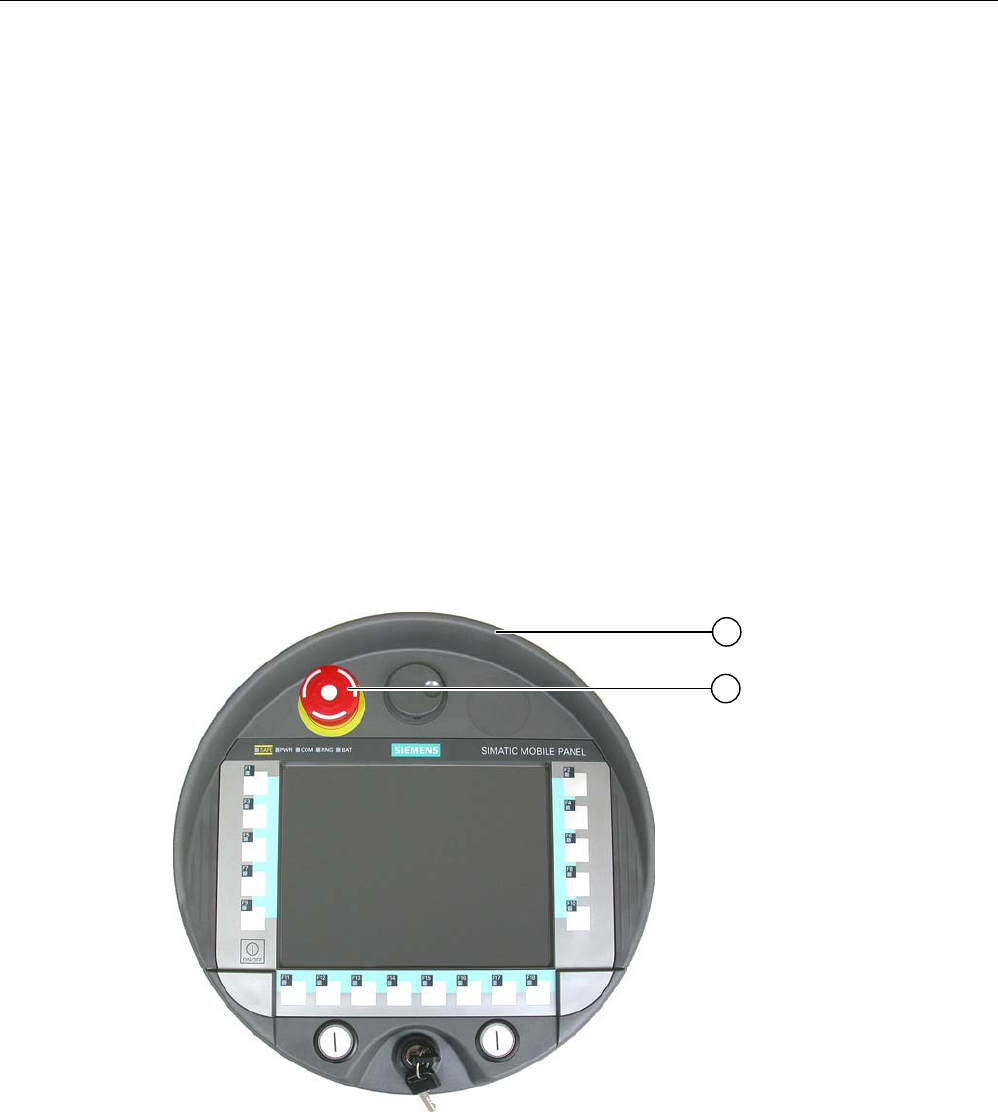
Operator controls and displays
5.4 Safety-related operator controls
Mobile Panel 277F IWLAN
100 Operating Instructions, 12/2007, A5E01003940-01
5.4 Safety-related operator controls
5.4.1 Emergency stop button
Introduction
The emergency stop button is designed with 2-channels and enables an emergency stop of
the configured system.
The emergency stop button satisfies the requirements specified in DIN IEC 60947-5-5;1997
Annex K.
For additional safety instructions please refer to the section titled "Safety instructions,
standards and notes".
When using the emergency stop button the following F-FBs must be linked in the safety
program of the F CPU:
● F_FB_MP
● F_FB_RNG_n
① Fall protection
② Emergency stop button
Due to its position, the emergency stop button is equally accessible for both left-handed and
right-handed persons.
Due to its profiled design, the emergency stop button is easily accessible. A collared
enclosure serves as protection if the device falls. Thus if the Mobile Panel 277F IWLAN
Operator controls and displays
5.4 Safety-related operator controls
Mobile Panel 277F IWLAN
Operating Instructions, 12/2007, A5E01003940-01 101
should fall down, the emergency stop button will not be activated. However the emergency
stop button is extensively protected against damage.
Operation
The operator triggers the emergency stop by pressing the emergency stop button. The
emergency stop button engages in the emergency stop position.
Releasing the emergency stop button
WARNING
If you have activated the emergency stop button and thereby brought the configured
system to a standstill, the emergency stop button should only be released under the
following conditions:
• The reasons for the emergency stop have been eliminated.
• A safe restart is possible.
• The restart should not be executed by releasing the emergency stop button.
The operator must strictly ensure that he executes a separate operator action to
commence the restart. The safety program must ensure that release of the emergency
stop button alone does not trigger an automatic restart of the system.
In order to release the emergency stop button, turn it in a clockwise direction. The
emergency stop button then returns on its own to the initial position.
NOTICE
The emergency stop button can be triggered unintentionally
The emergency stop button is evaluated under the following conditions:
• The Mobile Panel 277F IWLAN is integrated in the safety program of the F CPU.
The emergency stop button can be triggered unintentionally in the following cases, and
bring the configured system to a standstill:
• If the HMI device falls down
• When opening one of the coverings on the rear of the HMI device
WARNING
Non-functional emergency stop button
The emergency stop button is only effective if the HMI device is in the charging station or if
is operated with the battery.
Do not operate the HMI device in the plant with the table power supply unit.
Operator controls and displays
5.4 Safety-related operator controls
Mobile Panel 277F IWLAN
102 Operating Instructions, 12/2007, A5E01003940-01
Storing the HMI device
WARNING
Non-functional emergency stop button
If the HMI device is not integrated in the safety program of the F CPU, the emergency stop
button does not function.
To avoid confusion between effective and non-effective emergency stop buttons, only one
integrated HMI device should be freely accessible.
If the HMI device is not in use, it must be stored in a locked cabinet.
See also
Safety functions of the emergency stop button (Page 43)
5.4.2 Enabling button
Introduction
The enabling device consists of the two enabling buttons mounted on both sides of the
Mobile Panel 277F IWLAN. The switch setting of the two enabling buttons is determined by
electrical momentary contact switches.
Note
The HMI device analyzes the switch settings of the two enabling buttons in the form of an
OR gate.
① Enabling button
Operator controls and displays
5.4 Safety-related operator controls
Mobile Panel 277F IWLAN
Operating Instructions, 12/2007, A5E01003940-01 103
Operation
WARNING
Undesirable enabling function
Only push the enabling button until the operation which you enabled has been completed.
The enabling function is an intentional operator action. It is not permissible to constantly
hold the enabling button or lock it otherwise.
If you leave the effective range only briefly for a time period of up to 30 seconds while the
enabling button is pressed, the following occurs: 5 seconds after you have left the effective
range, the enabling function is revoked. If you return to the effective range within 30
seconds with the enabling button still pressed, the enabling function is automatically
returned.
The enabling button has three switch settings:
● Neutral position: The enabling button is not pressed.
● Enable: The enabling button is pressed to a mid position. This switch setting is used to
allow another command, for example an input with the membrane keyboard.
● Panic: The switch setting "Panic" is achieved as soon as one of the enabling buttons
have been pressed. The switch setting of the other enabling button is irrelevant in this
case. The switch setting "Panic" has the same effect as releasing the enabling button,
namely revoking the enable.
You only have to activate one enabling button. The PLC receives the same signal regardless
of whether only one or both enabling buttons of the Mobile Panel 277F IWLAN having been
pushed.
Note
The enabling button and the membrane keyboard can be operated at the same time.
When using the enabling button the following F-FBs must be linked in the safety program of
the F CPU:
● F_FB_MP
● F_FB_RNG_n
Switch settings
The following figure shows the switching sequence for enable.
(%(QDEOLQJEXWWRQ
1HXWUDOSRVLWLRQ
(%OHIW(%ULJKW
(%OHIW(%ULJKW
6ZLWFKVHWWLQJ
(QDEOH
1HXWUDOSRVLWLRQ
[ \
[
\
Operator controls and displays
5.5 Operator controls
Mobile Panel 277F IWLAN
104 Operating Instructions, 12/2007, A5E01003940-01
The following figure shows the switching sequence during panic usage.
(%(QDEOLQJEXWWRQ
1HXWUDOSRVLWLRQ
(%OHIW(%ULJKW
(%OHIW(%ULJKW
6ZLWFKVHWWLQJ
(QDEOH
3DQLF 1HXWUDOSRVLWLRQ
[ X
[
X
\
\
If the operator has pressed the enabling button through to the "Panic" setting, the "Enable"
setting will not be evaluated when leaving the panic setting. A new enable can only be
triggered by releasing the enabling button.
5.5 Operator controls
5.5.1 Handwheel
Introduction
The handwheel is an optional operator control on the Mobile Panel 277F IWLAN. The
handwheel can be turned without a stop and does not have a zero position.
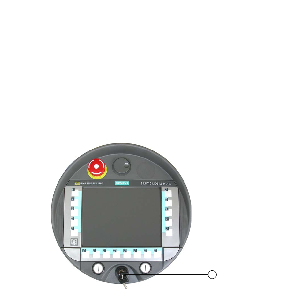
Operator controls and displays
5.5 Operator controls
Mobile Panel 277F IWLAN
Operating Instructions, 12/2007, A5E01003940-01 105
① Handwheel with recess
Operation
To facilitate operation, the handwheel has a small recess.
5.5.2 Key-operated switch
Introduction
The key-operated switch is an optional operator control on the Mobile Panel 277F IWLAN.
The key-operated switch is used to lock functions that can be triggered via the
Mobile Panel 277F IWLAN.
① Key-operated switch
Operation
The followinig figure shows the three switch positions of the key-operated switch, I-0-II.
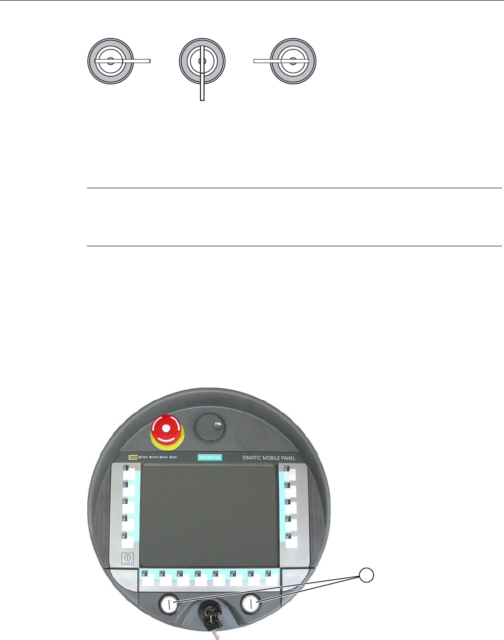
Operator controls and displays
5.5 Operator controls
Mobile Panel 277F IWLAN
106 Operating Instructions, 12/2007, A5E01003940-01
,,,
The key can be removed in the switch setting 0.
Remove the key after use. This avoids possible damage to the key if the HMI device falls
down.
Note
The key to the key-operated switch is supplied together with the HMI device. The key does
not have an HMI device-dependent coding. This means the key can be used on any
Mobile Panel 277F IWLAN.
5.5.3 Illuminated pushbutton
Introduction
The illuminated pushbuttons are optional operator controls on the
Mobile Panel 277F IWLAN. The illuminated pushbuttons are available for fast digital inputs.

Operator controls and displays
5.5 Operator controls
Mobile Panel 277F IWLAN
Operating Instructions, 12/2007, A5E01003940-01 107
① Illuminated pushbutton
5.5.4 Evaluation of the operator controls
5.5.4.1 Overview
Operator controls
The following information can be transferred between the HMI device and the PLC:
● Direction pulses of the handwheel
● Status of the function keys
● Status of the key-operated switch
● State of the illuminated pushbuttons
● State of the function keys and illuminated pushbutton LEDs
There are two ways of transmitting information:
● Direct keys
● System functions of WinCC flexible
Note
The following sections are intended for the configuration engineer of the HMI device.
5.5.4.2 Evaluating operator controls as direct keys
Introduction
You can configure the operator controls of the HMI device as direct keys.
The states of the following operator controls are available directly in the I/O area of the PLC:
● Direction pulses of the handwheel
● The switching state of the function keys
● The switching state of the key-operated switch
● The switching state of the illuminated pushbuttons
Byte assignment
The following figure shows the assignment of the keys (inputs) and LEDs (outputs) to the
bytes in the PLC process image.
Check whether additional information is available in your plant documentation.
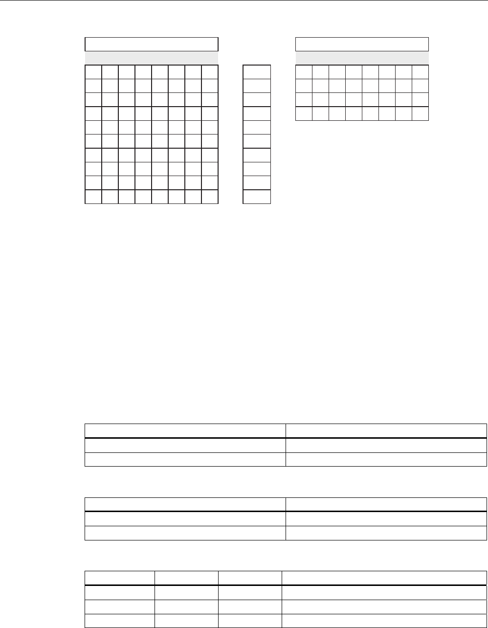
Operator controls and displays
5.5 Operator controls
Mobile Panel 277F IWLAN
108 Operating Instructions, 12/2007, A5E01003940-01
%XWWRQELWV /('ELWV
%\WH
) ) ) ) ) ) ) )
) ) ) ) ) ) ) )
) )
7 7
) ) ) ) ) ) ) )
) ) ) ) ) )
) )
) )
7 7 6 6
, , , , , , , ,
' ' ' ' ' ' ' '
Q
Q
Q
Q
Q
Q
Q
Q
Q
Q
F Bit for function key
S Bit for key-operated switch
T1 Bit for left illuminated pushbutton
T2 Bit for right illuminated pushbutton
I Bit for handwheel pulses, forwards
D Bit for handwheel pulses, backwards
The bytes "n+6" to "n+9" contain the direct key bits for the touch buttons.
Bit coding
The following tables show the bit coding for function keys, key-operated switch, illuminated
pushbutton and handwheel:
● Bit coding of function keys
State F1 to F18
Not pressed 0
Pressed 1
● Bit coding of function key LEDs
State F1 to F18
LED not illuminated 0
LED is illuminated 1
● Bit coding of key-operated switch
State S1 S0 Key position
Position 0 0 0 In middle position
Position I 0 1 Turned in clockwise direction up to stop
Position II 1 0 Turned counter-clockwise up to stop
● Bit coding of illuminated pushbuttons

Operator controls and displays
5.5 Operator controls
Mobile Panel 277F IWLAN
Operating Instructions, 12/2007, A5E01003940-01 109
State T1 T2
Not pressed 0 0
Pressed 1 1
● Bit coding of illuminated pushbutton LEDs
LED status T1 T2
Off 0 0
On permanently 1 1
● Bit coding of handwheel
– A setpoint is not specified for the handwheel.
– After start-up of the HMI device, the bytes "n+4" to "n+5" are set to zero.
Rotation of the handwheel produces positive or negative pulses depending on the
rotation direction. The number of positive pulses are stored in bits I0 to I7. The number
of negative pulses are stored in bits D0 to D7. The values are entered in binary format,
where bit 0 is the lowest and bit 7 is the highest valued bit.
A complete handwheel revolution yields 50 pulses.
– Every pulse of the handwheel is added to byte "n+4" or "n+5" depending on the
direction of rotation. There are no negative values. When the possible value range is
exceeded, there is an overflow:
If a value of 255 is increased by one pulse, a value of 0 results.
Example of bit coding for handwheel
The following table includes an example for rotation direction determination. The pulses are
stored in bytes "n+4" and "n+5" and are measured during the points in time t1 to t4.
The numbers in the following table represent a byte in the PLC.
Handwheel Evaluation time
Pulses, forwards Pulses, backwards
Evaluation
t1 255 (≙ -1) 245 (≙ -11) --
t2 10 245 (≙ -11) Pulses, forwards: 11
Pulses, backwards: 0
Resulting value: +11
t3 10 4 Pulses, forwards: 0
Pulses, backwards: 15
Resulting value: -15
t4 15 5 Pulses, forwards: 5
Pulses, backwards: 1
Resulting value: +4
The difference in pulses at times tn and tn+1 allows you to determine the resulting value and
thus the direction of rotation.
Establish the following values:

Operator controls and displays
5.5 Operator controls
Mobile Panel 277F IWLAN
110 Operating Instructions, 12/2007, A5E01003940-01
● Number of pulses, forwards
– At time tn
– At time tn+1
● Number of pulses, backwards
– At time tn
– At time tn+1
From this, you determine the resulting value. This is calculated as:
Pulses, forwards, tn+1
– Pulses, forwards, tn
– Pulses, backwards, tn+1
+ Pulses, backwards, tn
= Resulting value
Reaction time
The bytes "n+4" and "n+5" must be retrieved on the PLC side within a second and cyclically.
This ensures that no more than 256 pulses can be added between two scans of the
handwheel. For 256 pulses, approximately 4.5 revolutions of the handwheel are required.
The rotary pulse encoder supplies a maximum of 200 pulses per second.
NOTICE
Sample cycle time
The input pulses should take effect immediately on the PLC and cause a response in the
system. Set a scan cycle ≤ 100 ms in the PLC in order to achieve this.
See also
Direct keys (Page 234)
5.5.4.3 Activation of function key LEDs using system functions
Application
LEDs are integrated in the HMI device's function keys F1 to F18. The integrated LEDs can
be controlled from the PLC.
The LEDs can assume the following states:
● Off
● Flashing slowly
● Flashing quickly

Operator controls and displays
5.5 Operator controls
Mobile Panel 277F IWLAN
Operating Instructions, 12/2007, A5E01003940-01 111
● On
You can use the LED to signal to the user that a function key should be pressed, in a running
project.
Bit assignment
The following table shows the possible states of the LEDs and the corresponding entries in
bit n+1 and bit n of the LED tags.
Bit n+1 Bit n LED status
0 0 Off
0 1 Flashing quickly
1 0 Flashing slowly
1 1 ON (continuous)
5.5.4.4 Evaluation of the handwheel with system functions
Application
The handwheel is an optional operator control of the HMI device. You can enter incremental
values in a running project with the handwheel.
Note
Do not configure limit values in WinCC flexible for tags assigned to the handwheel.
Evaluation of the incremental values
If the signals of the handwheel are assigned to a WinCC flexible tag, then the forward and
backward increments will be set off against each other. The absolute value of the increments
is given. The maximum or minimum value of the increments until an overflow depends on the
type of tags assigned.
A complete handwheel revolution yields 50 pulses. The rotary pulse encoder supplies a
maximum of 200 pulses per second.
Example
● The handwheel has a starting value of 120 increments.
● You rotate the wheel 10 increments forwards and 3 increments backwards.
This results in a new value of 127 increments.

Operator controls and displays
5.5 Operator controls
Mobile Panel 277F IWLAN
112 Operating Instructions, 12/2007, A5E01003940-01
5.5.4.5 Evaluation of the key-operated switch with system functions
Application
The key-operated switch is an optional operator control of the HMI device. The key-operated
switch serves to lock functions in a running project which can be triggered by means of the
HMI device.
Bit assignment
The following table shows the bit assignment for the tag of the key-operated switch:
Bit 1 Bit 0 Key position
0 0 Central position
0 1 Turned in clockwise direction up to stop
1 0 Turned counter-clockwise up to stop
Note
If you use a tag of the "Boolean" type for the key-operated switch, the following assignment
applies:
• Status "0": Central position of the key-operated switch
• Status "1": Key-operated switch turned clockwise or counter-clockwise to the stop
5.5.4.6 Evaluation and activation of the illuminated pushbuttons
Application
The illuminated pushbuttons are optional operator controls of the HMI device. The integrated
LEDs can be controlled from the PLC.
The LEDs can assume the following states:
● Off
● Flashing slowly
● Flashing quickly
● On
You can use the LEDs to signal to the user that a function key should be pressed in a
running project.
Bit assignment
The following table shows the bit assignment for the status tags of the illuminated
pushbuttons:

Operator controls and displays
5.6 Using a memory card with the HMI device
Mobile Panel 277F IWLAN
Operating Instructions, 12/2007, A5E01003940-01 113
Bit 0 Status of the illuminated pushbutton
0 Pressed
1 Not pressed
The following table shows the bit assignment for the LED tags of the illuminated
pushbuttons:
Bit n+1 Bit n LED status
0 0 Off
0 1 Flashing quickly
1 0 Flashing slowly
1 1 ON (continuous)
5.6 Using a memory card with the HMI device
Introduction
The following can be saved to the memory card of the HMI device:
● Logs
● Recipes
● Operating system
● Applications
● Additional specifications
The memory card can be inserted and removed during operation. Do not remove the
memory card while data is being accessed by an application, for example during backup or
recipe transfer.

Operator controls and displays
5.6 Using a memory card with the HMI device
Mobile Panel 277F IWLAN
114 Operating Instructions, 12/2007, A5E01003940-01
Instructions
CAUTION
Malfunctions
If the HMI device is resting on its front, the following can be activated:
• The emergency stop button
This can bring the system to a standstill unintentionally.
• The key-operated switch or an illuminated pushbutton
This can result in malfunctions.
ESD
When working in the open housing, ensure that current-carrying conductors do not come
into contact with electrical circuits.
Note the ESD instructions.
CAUTION
Possibility of shutdown while logging onto the effective range
If the HMI device no longer recognizes the transponder and, therefore, the measuring
range, it triggers a shutdown.
To remove or insert the memory card, rest the HMI device on its front. Align the HMI device
so that it is still possible to measure the distance between the HMI device and the
transponder. Distance measurement between HMI device and transponder (Page 61)
If possible, log the HMI device off from the effective range.
CAUTION
Shutdown or rampdown of the system
When you insert or remove the memory card, remove the main battery. This failure of the
main battery is bridged by the bridge battery, if fitted. The maximum buffer time is 5
minutes. If you do not replace the main battery after 5 minutes, the HMI device will switch
off. If the HMI device has been integrated, this will lead to a shutdown or rampdown of the
system.
Do not exceed the buffer time!
NOTICE
Multimedia card
The multimedia card of the SIMATIC S7 PLC cannot be used.
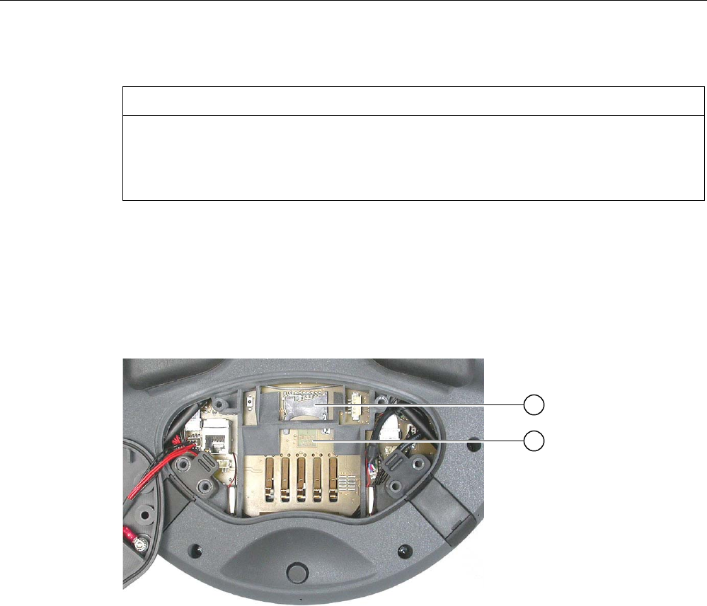
Operator controls and displays
5.6 Using a memory card with the HMI device
Mobile Panel 277F IWLAN
Operating Instructions, 12/2007, A5E01003940-01 115
NOTICE
Pay attention to cleanliness. Foreign bodies or liquids must not come into contact with the
printed circuit board or penetrate the inside of the HMI device.
Place the HMI device with the front side facing down on a flat, clean surface to protect
against damage.
Requirements
● You have opened the battery compartment of the HMI device
● The main battery is removed
● You have opened the connection bay of the HMI device
① Slot
② Memory card symbol
Procedure for inserting a memory card
Proceed as follows:
1. Insert the memory card into the slot.
Pay attention to the memory card symbol when inserting the memory card. An arrow on
the memory card indicates the front side and the direction of insertion. When the memory
card is correctly inserted into the slot, it stands approx. 3 mm proud of the slot.

Operator controls and displays
5.7 Labeling the function keys
Mobile Panel 277F IWLAN
116 Operating Instructions, 12/2007, A5E01003940-01
Using a memory card for the first time
NOTICE
Data loss
If the HMI device asks you to perform formatting the first time you use a memory card, back
up any existing data on the memory card first.
Proceed as follows in order to prevent data loss:
1. Cancel the formatting procedure by pressing "ESC".
2. Remove the memory card from the HMI device.
3. Back up any data that you do not want to lose on the memory card.
4. Insert the memory card into the HMI device.
5. Format the memory card on the HMI device.
Procedure for unplugging a memory card
Proceed as follows:
1. Pull the memory card out of the slot.
2. Close the connection bay.
3. Replace the main battery.
4. Close the HMI device's battery compartment.
5. Store the memory card in a safe place.
See also
Distance measurement between HMI device and transponder (Page 61)
Opening and closing the terminal compartment (Page 71)
5.7 Labeling the function keys
Introduction
You can label the function keys as required for your project. Use labeling strips to do so.
NOTICE
Do not write on the keyboard to label the function keys.
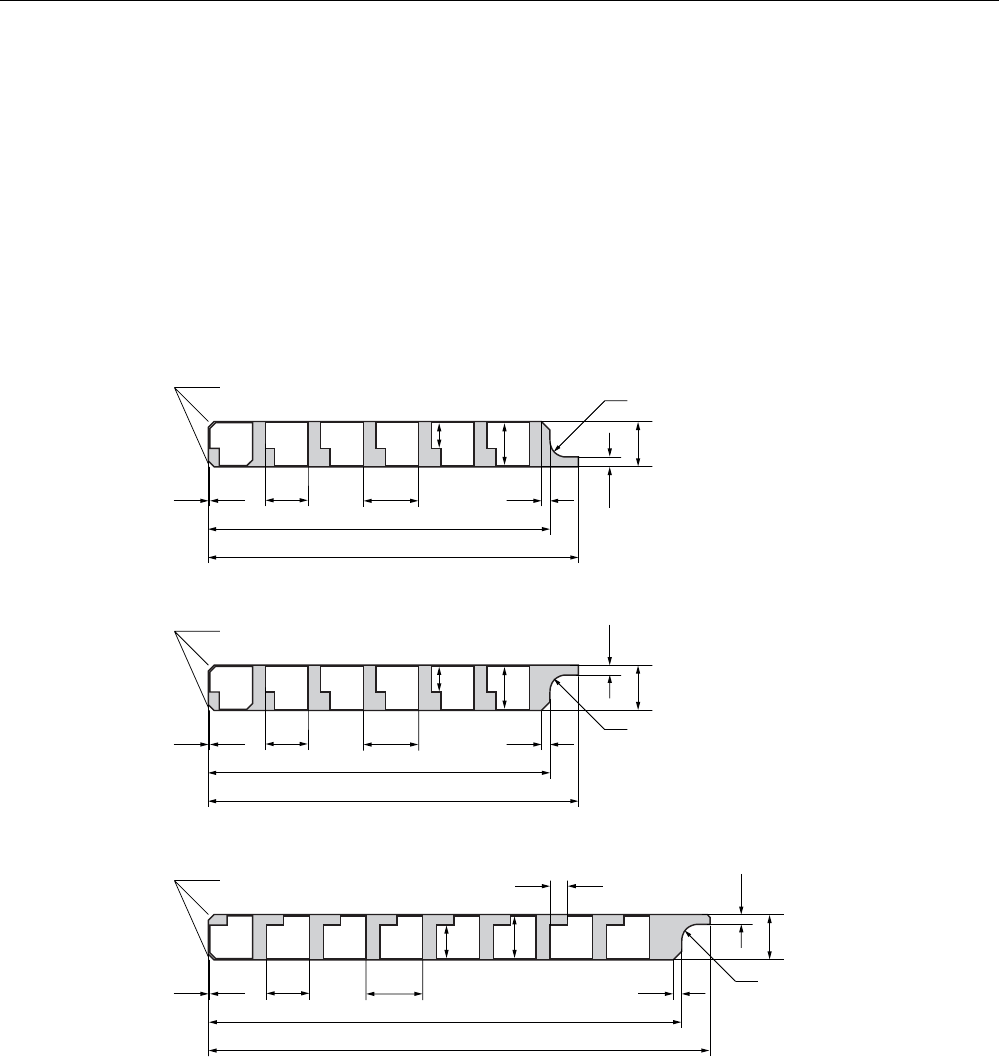
Operator controls and displays
5.7 Labeling the function keys
Mobile Panel 277F IWLAN
Operating Instructions, 12/2007, A5E01003940-01 117
Printing labeling strips
WinCC flexible comes with a range of labeling strip templates. You will find further
information regarding the location of the templates in the WinCC flexible Online Help.
Any printable and writable foil can be used as labeling strips. Use transparent foil so that the
LEDs of the function keys can be seen. The permitted thickness of the labeling strip is 0.13
mm. Paper should not be used as labeling strips.
Labeling strip dimensions
$OOGLPHQVLRQVLQPP
/DEHOLQJVWULSRQULJKW
/DEHOLQJVWULSRQOHIW
/DEHOLQJVWULSDWERWWRP
[
[r
5
ದ
[r
[
ದ
5
[r
[
5
ದ
Procedure for attaching the labeling strips
The following steps apply for the initial attaching of labeling strips.
Proceed as follows:
1. Lay the HMI device on its reverse side.
2. Remove the label ① from the cover caps.
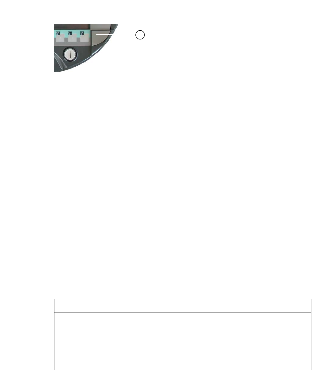
Operator controls and displays
5.8 Holding the mobile panel and fixing it to the wall
Mobile Panel 277F IWLAN
118 Operating Instructions, 12/2007, A5E01003940-01
1. Unscrew both cover caps.
2. Pull the labeling strips out of the guides.
3. Inscribe the labeling strips in accordance with the system.
Wait for the printed labeling strips to dry before you insert them.
4. Push the labeling strips into the guides.
5. Screw both cover caps back on.
Screwed on cover caps with inserted rubber seals satisfy degree of protection IP65.
6. Place the label on to the cover caps.
Procedure for exchanging the labeling strips
Should the exchange of labeling strips become necessary, these can be reordered.
See also
Supplementary pack and other accessories (Page 20)
5.8 Holding the mobile panel and fixing it to the wall
Holding the HMI device
CAUTION
Rampdown
If the HMI device is logged onto an effective range and more than 5 seconds pass without it
recognizing the effective range, the enabling button is deactivated.
If a further 25 seconds pass without the HMI device recognizing the effective range, the
HMI device triggers a local rampdown.
Always align the HMI device towards the transponder.

Operator controls and displays
5.8 Holding the mobile panel and fixing it to the wall
Mobile Panel 277F IWLAN
Operating Instructions, 12/2007, A5E01003940-01 119
The method of holding the HMI device illustrated above enables you, for example, to move
around while servicing the system to be monitored.
NOTICE
Availability of the safety-related operator controls
If you are manually controlling potentially dangerous movements in the special operating
modes, you must use the above shown forearm holding method. Holding the HMI device so
that it is supported on your forearm in this way enables you, for example, to quickly reach
the emergency stop button or the enabling button in the event of a dangerous situation.
Availability of the enabling button and emergency stop button
The HMI device is equally easy to hold for right-handers and left-handers because it is
designed symmetrically. The free hand can be used to operate the operator controls on the
front side. The hand holding the HMI device can also be used to activate the enabling button.
The acknowledgment of the control input is also given if you only press one of the enabling
buttons.
The enabling button is required to confirm axis movements, for example. The enabling
button is optimally accessible. The enabling button triggers a safety shutdown in the event of
a panic reaction to danger (release or cramping).
The emergency stop button can also be quickly reached with your free hand.
Holder for the HMI device
NOTICE
Operability of the emergency stop button impaired
If the HMI device is hooked into an unsuitable wall holder, the operability of the emergency
stop button can be impaired.
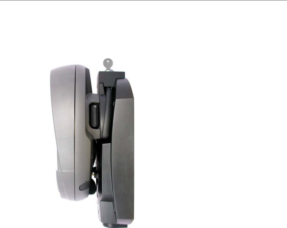
Operator controls and displays
5.9 Charging station
Mobile Panel 277F IWLAN
120 Operating Instructions, 12/2007, A5E01003940-01
A charging station is available for safe accommodation of the HMI device. The HMI device is
used as a stationary HMI device when it is hooked into the charging station. The HMI
device's battery is charged in the charging station.
5.9 Charging station
5.9.1 Charging batteries in the charging compartment
Introduction
You can charge one main battery in each of the two charging compartments of the charging
station. The batteries are charged independently of each other.
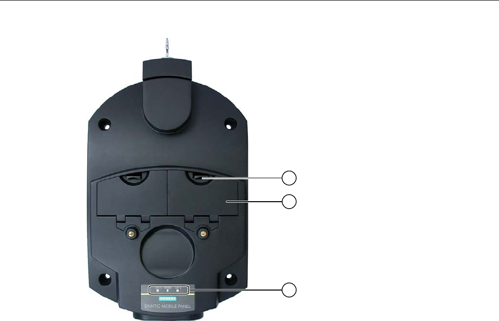
Operator controls and displays
5.9 Charging station
Mobile Panel 277F IWLAN
Operating Instructions, 12/2007, A5E01003940-01 121
① Locking latch for charging compartment cover
② Charging compartment
③ LED display
Procedure for inserting the battery in the charging compartment
Proceed as follows:
1. Pull up the locking latch on the charging compartment cover.
The cover can now be opened.
2. Place the battery in the charging compartment.
3. Close the charging compartment.
Result
The battery is charged automatically whenever the charging station is connected to the
power supply unit. The LED display shows the battery's charging status.
Procedure for removing the battery from the charging compartment
Proceed as follows:
1. Pull up the locking latch on the charging compartment cover.
The cover can now be opened.
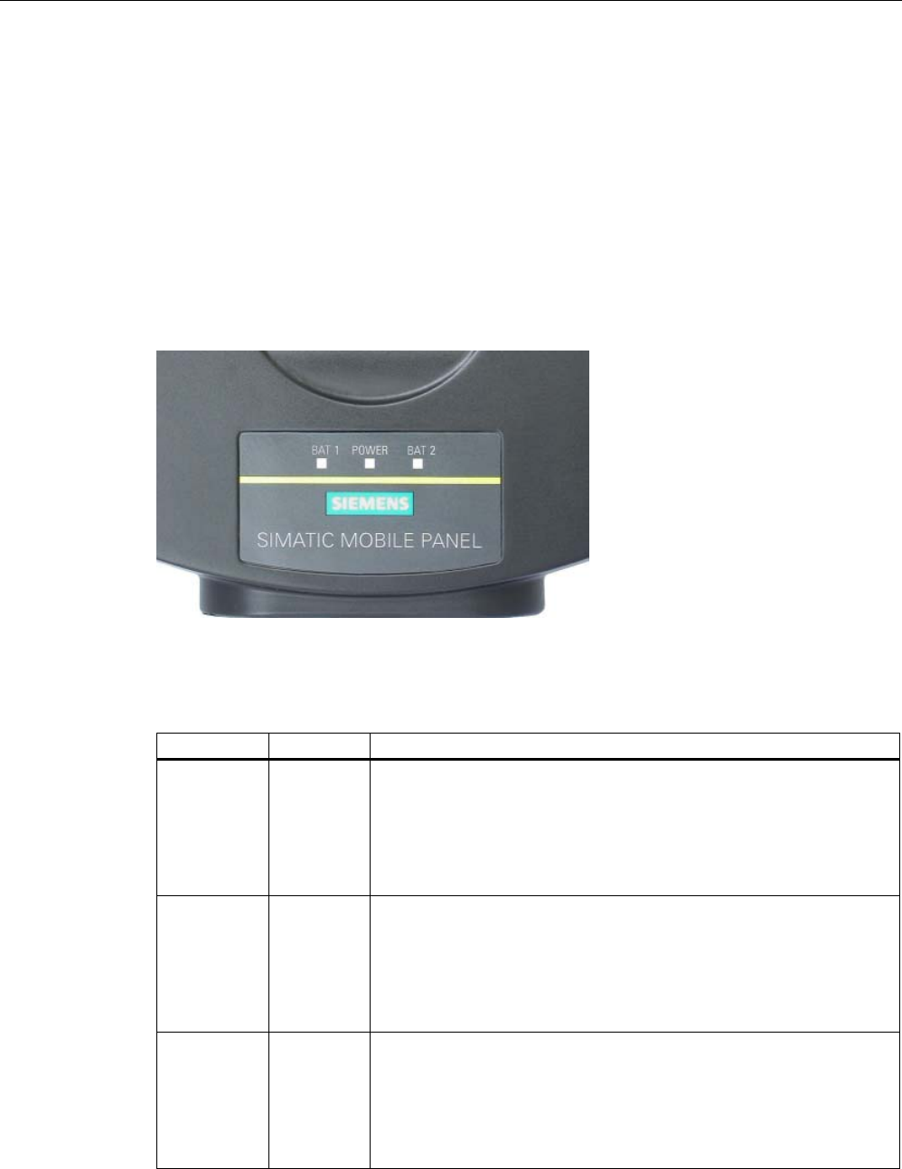
Operator controls and displays
5.9 Charging station
Mobile Panel 277F IWLAN
122 Operating Instructions, 12/2007, A5E01003940-01
2. Remove the main battery using the ribbon.
3. Close the charging compartment.
5.9.2 Displays on the charging station
Introduction
There are 3 LEDs on the charging station. The LEDs show the states of the batteries in the
charging compartments and of the power supply unit.
Meaning of the LED displays
Designation Color Meaning
BAT 1 Green The "BAT 1" LED is off when there is no battery in the first charging
compartment.
The "BAT 1" LED flashes when the battery in the first charging
compartment is being charged.
The "BAT 1" LED lights up when the battery in the first charging
compartment is 95% charged.
BAT 2 Green The "BAT 2" LED is off when there is no battery in the second charging
compartment.
The "BAT 2" LED flashes when the battery in the second charging
compartment is being charged.
The "BAT 2" LED lights up when the battery in the second charging
compartment is 95% charged.
POWER Green/red The "POWER" LED is off when there is no voltage supply to the
charging station.
The "POWER" LED lights up green when the power supply to the
charging station is within the nominal range.
The "POWER" LED lights up red when there is an overvoltage or
undervoltage at the charging station.
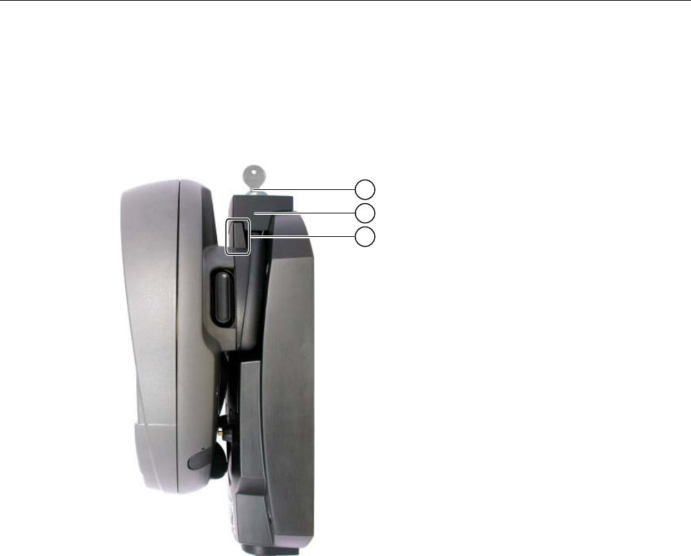
Operator controls and displays
5.9 Charging station
Mobile Panel 277F IWLAN
Operating Instructions, 12/2007, A5E01003940-01 123
5.9.3 Locking the charging station
Introduction
The lock prevents unauthorized removal of the HMI device from the charging station.
① Lock barrel with key
② Lock
③ Hook for hooking in the HMI device
Procedure for locking the charging station
Proceed as follows:
1. Slide the lock down to the appropriate cut-out in the charging station.
2. Turn the key by 90 degrees.
3. Remove the key.
Result
The charging station is locked. You cannot remove the HMI device.

Operator controls and displays
5.9 Charging station
Mobile Panel 277F IWLAN
124 Operating Instructions, 12/2007, A5E01003940-01
Procedure for unlocking the charging station
Proceed as follows:
1. Insert the key into the lock barrel.
2. Turn the key by 90 degrees.
3. Slide the lock upwards.
Result
You can now remove the HMI device.
See also
Charging station (Page 22)
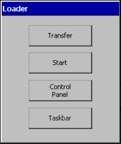
Mobile Panel 277F IWLAN
Operating Instructions, 12/2007, A5E01003940-01 125
Configuring the operating system 6
6.1 Loader
Loader
The following figure shows the Loader.
The buttons on the Loader have the following function:
● The "Transfer" button sets the HMI device to transfer mode
The transfer mode can only be activated when at least one data channel has been
enabled for the transfer.
● Press the "Start" button to start the project on the HMI device
If you do not perform an operation, the project on the HMI device will automatically start
after a delay, depending on settings.
● Press the "Control Panel" button to open the HMI device Control Panel
You can change various settings in the Control Panel, for example the transfer settings.
● Press the "Taskbar" button to activate the taskbar with the Windows CE start menu open
The following figure shows the open start menu.
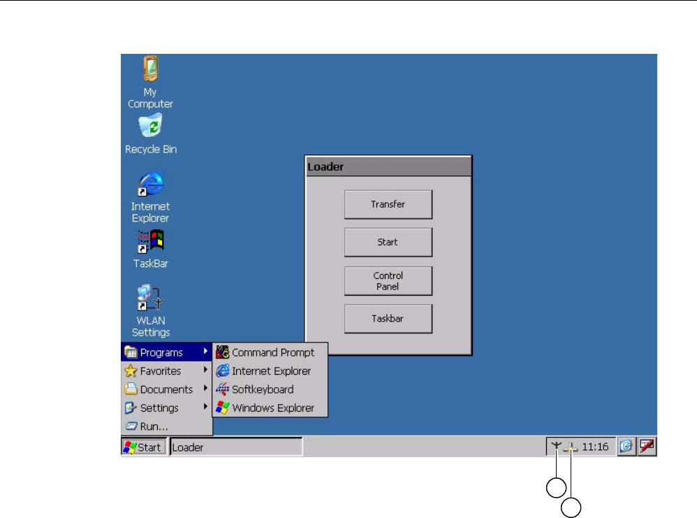
Configuring the operating system
6.1 Loader
Mobile Panel 277F IWLAN
126 Operating Instructions, 12/2007, A5E01003940-01
① Symbol for parameter assignment for the WLAN network
② Symbol for displaying IP information about the LAN connection
Open Loader
The following options are available to open the Loader:
● The Loader appears briefly after starting the HMI device
● The Loader appears when the project is closed
If configured, use the relevant operating element to close the project.
Please refer to your system documentation to check whether additional information on
this subject is available there.
Configuring the operating system
6.1 Loader
Mobile Panel 277F IWLAN
Operating Instructions, 12/2007, A5E01003940-01 127
Password protection
NOTICE
If the password is no longer available, you cannot do the following until you have updated
the operating system.
• Making changes to the Control Panel
• Operating the Windows CE task bar
All data on the HMI device will be overwritten when you update the operating system!
You can protect the Control Panel and taskbar from unauthorized access. When password
protection is enabled, the message "password protect" is displayed in the Loader.
Password protection prevents maloperations and increases security for the system or
machine.
If the password is not entered, only the "Transfer" and "Start" buttons are operable.
Internet Explorer
Internet Explore for Windows CE is installed on the HMI device.

Configuring the operating system
6.2 WLAN
Mobile Panel 277F IWLAN
128 Operating Instructions, 12/2007, A5E01003940-01
Note
Internet Explorer for Windows CE and the Internet Explorer version which can run on a PC
differ in terms of functionality.
For further information, please refer to Microsoft's website.
See also
Changing password protection (Page 146)
Programming the data channel (Page 160)
Switching on and testing the HMI device (Page 91)
6.2 WLAN
6.2.1 Overview
Introduction
The properties of the WLAN networks can be entered in the "WLAN" dialog box. Open the
"WLAN" dialog box in Windows CE.
WLAN connection
In the case of a WLAN connection, the configuration engineer for the current project can
specify the following:
● The WLAN networks to which the HMI device connects
The configuration engineer can specify up to 3 WLAN networks
● Priority assignment of WLAN networks
● Whether the HMI device is permitted to connect with other WLAN networks
Procedure
You have activated the taskbar in Windows CE and opened the following dialog box with the
"WLAN Settings" or icon.
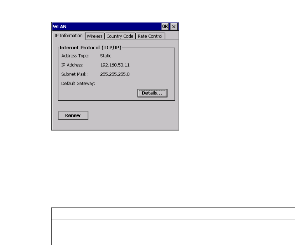
Configuring the operating system
6.2 WLAN
Mobile Panel 277F IWLAN
Operating Instructions, 12/2007, A5E01003940-01 129
The dialog box shows the parameters of the WLAN connection that are set in the "'WLAN'-
Settings" dialog box in the Control Panel. If you have not yet parameterized the connection,
the boxes will be empty.
Select the "Details..." button to open a dialog box which provides more detailed information
about the established network connection.
Set country code
NOTICE
The correct country setting is essential for operation complying with the approvals. The
selection of a country other than the one where you are using the system is subject to
criminal penalties.
For WLAN communication, the frequency bands are split into channels differently in different
countries.
1. Change to the "Country Code" tab.
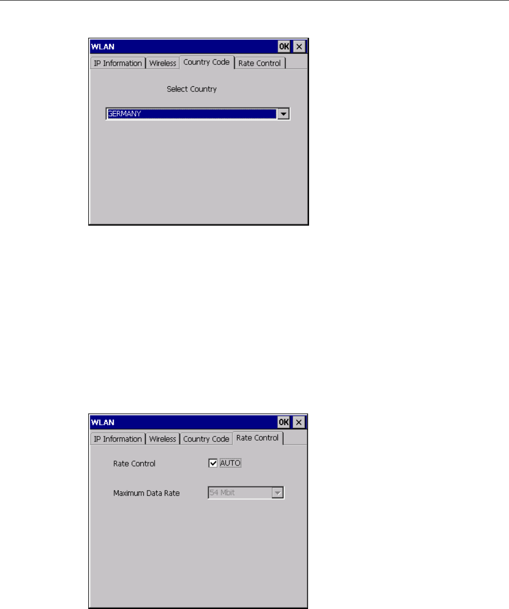
Configuring the operating system
6.2 WLAN
Mobile Panel 277F IWLAN
130 Operating Instructions, 12/2007, A5E01003940-01
1. Select the required country code from the "Country Code" selection box.
2. Confirm your entries.
The dialog closes.
Result
The country code for the WLAN connection has been set.
Setting the transmission rate for WLAN
Use the register "Rate Control" to change the transfer rate of the HMI panel, if necessary.

Configuring the operating system
6.2 WLAN
Mobile Panel 277F IWLAN
Operating Instructions, 12/2007, A5E01003940-01 131
NOTICE
Communication not possible.
Deselect the "Auto" check box only in case of transfer problems.
If you want to change the transfer rate, please contact your network administrator.
Communication between HMI Panel and Access Point is not possible in case of incorrect
settings.
1. Deselect the "Auto" check box.
2. Select the desired data transfer rate in the Maximum Data Rate selection box.
3. Confirm your entries.
4. Confirm the message of the HMI device.
5. Restart the HMI device.
See also
Restarting the HMI device (Page 156)
6.2.2 Parameterizing the WLAN connection
Introduction
You can define the parameters for the WLAN connection and also create new WLAN
connections.
Requirements
You have opened the "WLAN" dialog box, "Wireless" tab, by touching either the "WLAN
Settings" icon or the icon.
If no connection to a WLAN network exists, all available WLAN networks are listed.
If a connection to a WLAN network exists, the following WLAN networks are displayed:
● The WLAN network to which the connection exists
● All parameterized networks
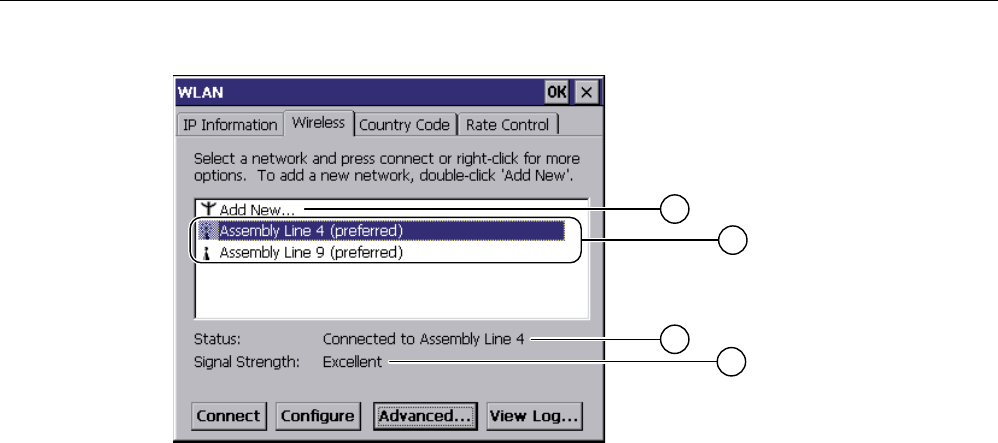
Configuring the operating system
6.2 WLAN
Mobile Panel 277F IWLAN
132 Operating Instructions, 12/2007, A5E01003940-01
① "Add New" entry
② Existing and parameterized WLAN networks
③ Status information, shows the WLAN network to which the HMI device is connected
④ Signal strength of the selected network
Procedure for creating a WLAN network, parameterize the WLAN network and establish a connection
1. If you want to create a new WLAN network, select "Add New".
2. If you want to configure an existing WLAN network or connect the HMI device to a WLAN
network, select the desired network.
3. Use the "Configure" or "Connect" button to open the "Wireless Network Properties" dialog
box.
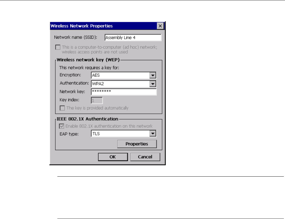
Configuring the operating system
6.2 WLAN
Mobile Panel 277F IWLAN
Operating Instructions, 12/2007, A5E01003940-01 133
Note
If the HMI device has detected the WLAN network, the encryption and the authentication
process for this network will already be shown in the dialog box.
If necessary, you must also enter the appropriate password in the "Network key" text box.
After you have entered the password, it is shown in encrypted form.
1. If necessary, select the encryption you are using under "Encryption".
2. If necessary, select the required authentication process under "Authentification".
3. If necessary, enter the password for the WLAN network under "Network key".
4. If necessary, select the type of authentication protocol under "EAP type".
5. Confirm your entries.
The dialog closes. The parameterized WLAN network is added to the list of preferred
networks.
If the HMI device is connected to the WLAN network, the WLAN network is put at the top
of the list of preferred networks.
Procedure for parameterizing list of preferred networks
1. In the "WLAN" dialog box, "Wireless" tab, press Advanced... to open the "Advanced
Wireless Settings" dialog box.
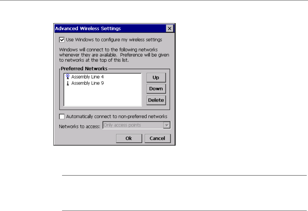
Configuring the operating system
6.2 WLAN
Mobile Panel 277F IWLAN
134 Operating Instructions, 12/2007, A5E01003940-01
1. If you want to block the connection to the parameterized networks in the list of preferred
networks, clear the "Use Windows to configure my wireless settings" check box.
Note
If preferred networks are configured in the project, the sequence of entries in the list of
preferred networks changes when you start a project. The sequence configured in the
project is set. Any networks not permitted in the project are removed from the list.
The HMI device attempts to connect with a WLAN network in the sequence of the
preferred networks in the list.
1. Change the sequence as required.
– Select the WLAN network you want to move.
– Use the "Up" and "Down" buttons to select the desired position.
2. If necessary, use the "Delete" button to delete the selected WLAN entry from the list of
preferred networks.
3. Select the "Automatically connect to non-preferred networks" check box if you want the
HMI device to connect to other WLAN networks.
4. Confirm your entries.
The dialog closes.
Result
The WLAN parameters are now set.
Display logbook
Press "View Log..." in the "WLAN" dialog box, "Wireless" tab, to open the logbook.
The logbook provides information about connection buildup, connection cleardown and failed
attempts at connection buildup.
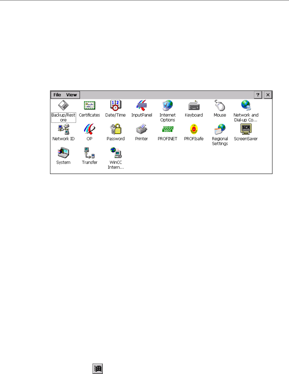
Configuring the operating system
6.3 Control Panel
Mobile Panel 277F IWLAN
Operating Instructions, 12/2007, A5E01003940-01 135
6.3 Control Panel
6.3.1 Overview
Control Panel of the HMI device
The HMI device Control Panel can be used to modify the following HMI device settings:
● PROFIsafe address
● Vibration alarm
● Date/time
● Screen saver
● Regional settings
● Transfer settings
● Network settings
● Delay time
● Password
Opening the Control Panel
The Control Panel can be opened as follows:
● In the startup phase
Press "Control Panel" to open the HMI device Control Panel in the Loader.
● In a running project
Select the operating element provided for the respective task, if configured.
● In the Windows CE start menu
– Press the key on the alphanumeric screen keyboard twice.
– Open the Control Panel with "Settings > Control Panel".
Configuring the operating system
6.3 Control Panel
Mobile Panel 277F IWLAN
136 Operating Instructions, 12/2007, A5E01003940-01
6.3.2 Reference
Overview of functions
The following table shows the settings in the Control Panel.
1) Additional tabs may appear in the "WinCC flexible Internet Settings" dialog. This depends on the options that have
been enabled for network operation in the project.
Icon Functions Tab / entry Chapter
Saving and restoring with external storage device –
Importing, displaying and deleting certificates "Stores"
Setting the date and time "Date/Time"
Configuring the screen keyboard –
Changing the browser startup page and general browser
settings
"General"
Changing connection and proxy server settings "Connection"
Changing cookie settings "Privacy"
Changing privacy settings "Advanced"
Setting the character repeat for the keyboard "Repeat"
Setting the double-click "Double-Click"
Parameterizing the WLAN connection "WLAN"
Setting the IP address 'WLAN' Settings' "IP Address"
Setting the name server 'WLAN' Settings' "Name Servers"
Parameterizing the LAN connection "LAN"
Setting the IP address 'LAN' Settings' "IP Address"
Setting the name server 'LAN' Settings' "Name Servers"
Changing the logon data "Identification"
Backup registry information "Persistent Storage"
Changing monitor settings "Display"
Displaying information about the HMI device "Device"
Restarting the HMI device "Device"
Calibrating the touch screen "Touch" Calibrating the touch
screen (Page 144)
Displaying battery status "Battery" Displaying battery
status (Page 181)
Activate memory management "Memory Monitoring" Activate memory
management
(Page 182)
Activating vibration alarm "Vibration Alarm" Activating vibration
alarm (Page 159)
Configuring the operating system
6.3 Control Panel
Mobile Panel 277F IWLAN
Operating Instructions, 12/2007, A5E01003940-01 137
Icon Functions Tab / entry Chapter
Changing password protection "Password Settings" Changing password
protection
(Page 146)
Changing the printer properties – Changing the printer
properties
(Page 154)
Changing the PROFINET IO setting – Enabling PROFINET
IO (Page 165)
Setting the PROFIsafe address Setting the
PROFIsafe address
(Page 164)
Changing regional settings "Regional Settings"
Changing the number format "Number"
Changing the currency format "Currency"
Changing the time format "Time"
Changing the date format "Date"
Changing regional
settings (Page 149)
Setting the screen saver
Reducing the backlighting
Setting the screen
saver (Page 152)
Displaying the system information "General"
Displaying memory information "Memory"
Displaying system
properties
(Page 158)
Setting the device name of the HMI device "Device Name" Setting the device
name of the HMI
device (Page 168)
Programming the data channel "Channel" Programming the
data channel
(Page 160)
Setting the delay time "Directories" Setting the delay
time (Page 162)
Changing e-mail settings1) "Email" Changing e-mail
settings (Page 172)
1) Additional tabs may appear in the "WinCC flexible Internet Settings" dialog. This depends on the options that have
been enabled for network operation in the project.
6.3.3 Operating the Control Panel
Introduction
The Control Panel is operated with the HMI device touch screen.
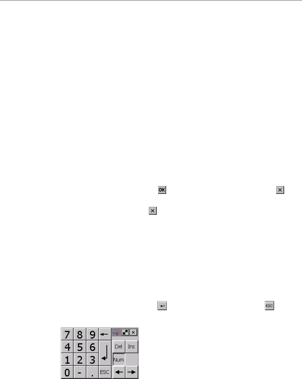
Configuring the operating system
6.3 Control Panel
Mobile Panel 277F IWLAN
138 Operating Instructions, 12/2007, A5E01003940-01
Procedure
Proceed as follows to change settings in the Control Panel:
1. Close the project.
Use the provided operating element.
The Loader appears
2. Open the Control Panel by pressing "Control Panel".
3. To open the required dialog, double-click its icon.
4. Change as required by touching the tab.
5. Now make the necessary changes.
Touch the respective input object to make entries.
– Use the screen keyboard of the HMI device to enter the new values in the text boxes.
– Touch a button to operate it.
– Touch the selection box to open a drop down list box. Touch the required entry from
the drop down list box.
– Touch the check box to select or clear a check box.
– Touch a radio button to select it.
6. Confirm the entries using the button or terminate the entries using the button .
The dialog closes.
7. Close the Control Panel with the button.
8. Start the project with the "Start" button in the Loader.
Input with the screen keyboard
A screen keyboard is available for alphanumeric characters. The screen keyboard is
displayed as soon as you touch a text box. You can also call up the screen keyboard directly
from the Control Panel.
Display methods for the screen keyboard
You can change the display method for the screen keyboard and fix the position on the
screen. Confirm an entry using the key or terminate the entry using the key . Either
action closes the screen keyboard.
● Numerical screen keyboard
● Alphanumerical screen keyboard
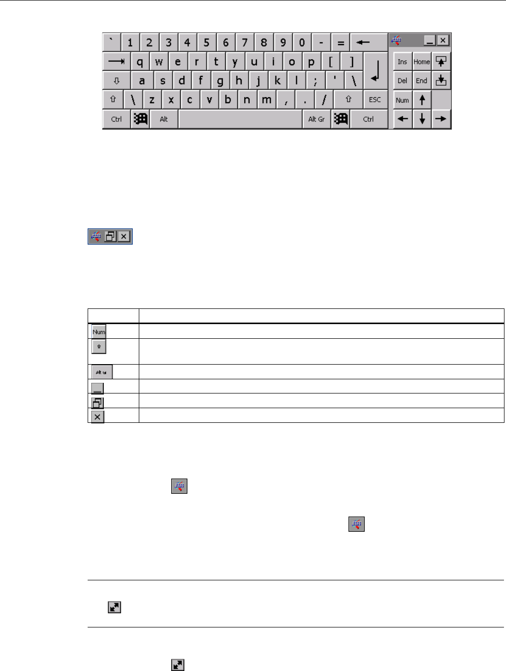
Configuring the operating system
6.3 Control Panel
Mobile Panel 277F IWLAN
Operating Instructions, 12/2007, A5E01003940-01 139
The alphanumerical screen keyboard has the following levels.
– Normal level
– Shift level
The shift level includes uppercase letters.
● Reduced screen keyboard
Changing the display of the screen keyboard
Key Functions
Switching between the numerical and alphanumerical keyboard
Switching between the normal level and Shift level of the alphanumerical screen
keyboard
Switchover to special characters
Switching from full display to reduced display
Switching from reduced display to full display
Closing of reduced display of the screen keyboard
Moving the screen keyboard
In order to move the screen keyboard, proceed as follows:
1. Touch the icon .
2. Touch and move the screen keyboard on the touch screen.
3. When the desired position is reached, release the icon .
Adjust screen keyboard size
Note
The icon only appears on the screen keyboard if in the "Siemens HMI InputPanel" dialog
box you have selected the "Show Resize button" check box.
To adjust the size of the screen keyboard, proceed as follows:
1. Touch the icon .
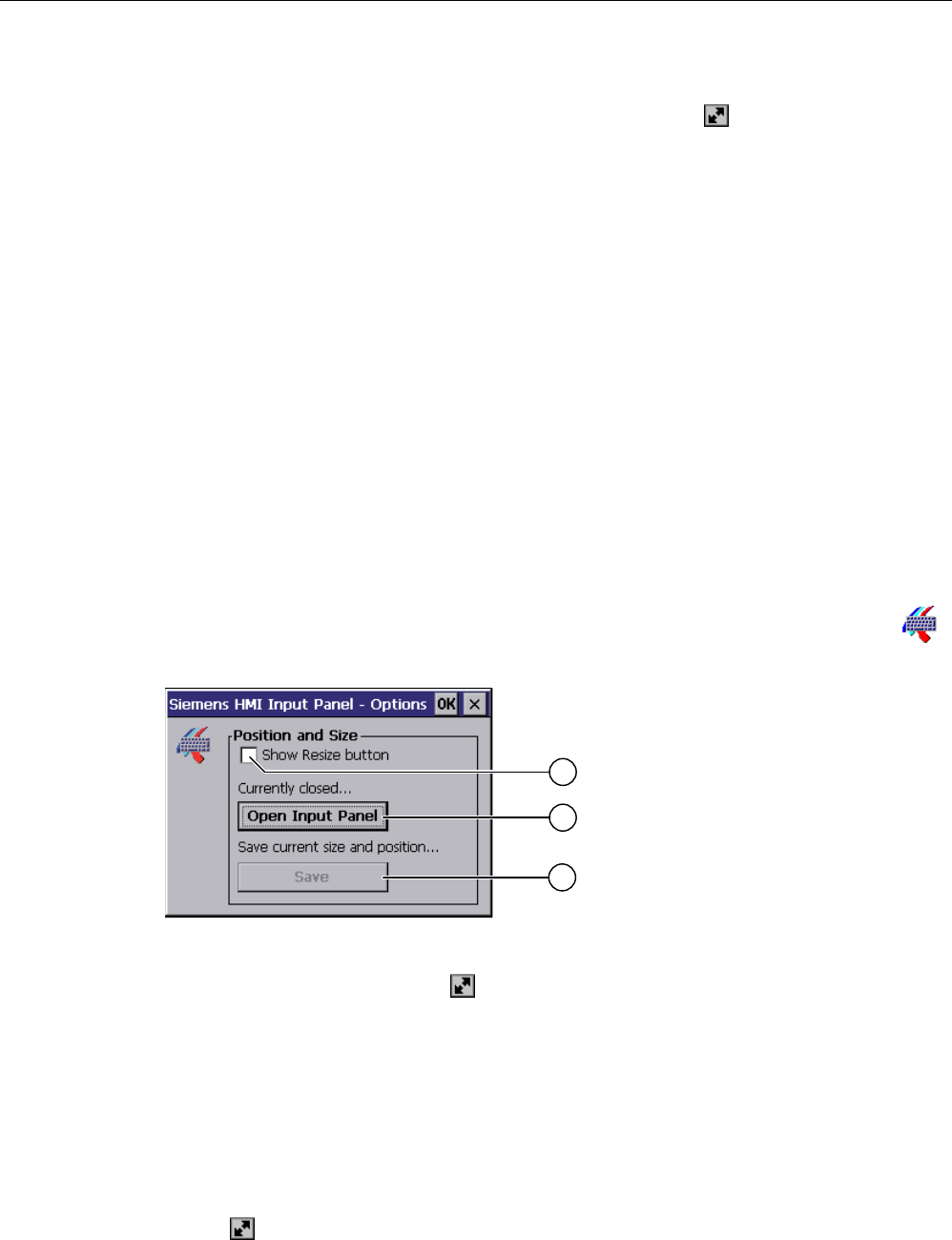
Configuring the operating system
6.4 Changing settings for operation
Mobile Panel 277F IWLAN
140 Operating Instructions, 12/2007, A5E01003940-01
2. To adjust the size of the screen keyboard, maintain contact.
3. When the size you want is reached, release contact with the icon.
See also
Configuring the screen keyboard (Page 140)
6.4 Changing settings for operation
6.4.1 Configuring the screen keyboard
Introduction
You can change the layout and the position of the screen keyboard as follows.
Requirements
You have opened the "Siemens HMI InputPanel - Options" dialog with the "InputPanel"
icon.
① Check box for displaying the button in the screen keyboard
② Button for displaying the screen keyboard
③ Button for saving the screen keyboard settings
Procedure
Proceed as follows:
1. If you want to change the size of the screen keyboard, activate the "Show Resize button"
check box.
The icon also appears in the screen keyboard.
2. Use the "Open Input Panel" button to open the screen keyboard.
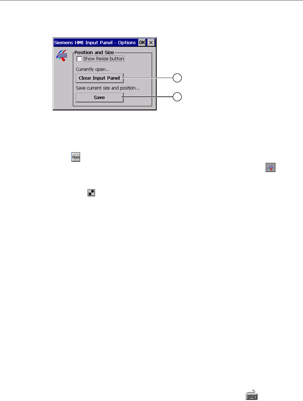
Configuring the operating system
6.4 Changing settings for operation
Mobile Panel 277F IWLAN
Operating Instructions, 12/2007, A5E01003940-01 141
The appearance of the dialog box changes:
① Button for closing the screen keyboard
② Button for saving the screen keyboard settings
1. If you want to switch between the numeric and alphanumeric screen keyboard, press
the key.
2. If you want to change the position of the screen keyboard, move it using the icon.
Release contact from the icon when the required position is reached.
3. If you want to increase the size of the screen keyboard, enlarge it to the size required
using the icon. Release contact from the icon when the required size is reached.
4. If you want to save the settings, press the "Save" button.
5. Close the screen keyboard by pressing the "Close Input Panel" button.
6. Confirm your entries.
The dialog closes.
Result
The screen keyboard settings have been modified.
See also
Operating the Control Panel (Page 137)
6.4.2 Setting the character repeat rate of the screen keyboard
Introduction
You can set the character repeat for the screen keyboard in the Control Panel.
Requirements
You have opened the "Keyboard Properties" dialog with the "Keyboard" icon.
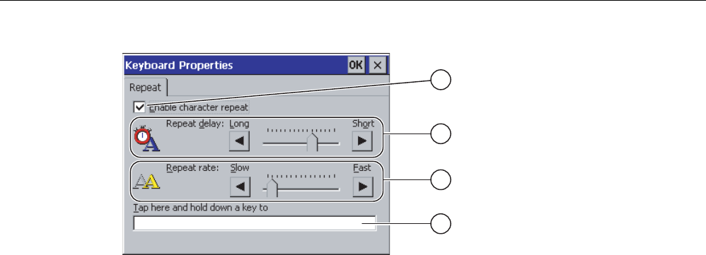
Configuring the operating system
6.4 Changing settings for operation
Mobile Panel 277F IWLAN
142 Operating Instructions, 12/2007, A5E01003940-01
① Check box for selecting the character repeat
② Slider control and buttons for the delay time before character repeat
③ Slider control and buttons for the rate of the character repeat
④ Test box
Procedure
Proceed as follows:
1. If you want to enable character repetition, select the "Enable character repeat" check box.
2. If you want to change the delay, press a button or the slider in the "Repeat delay" group.
Moving the slider to the right will shorten the delay. Moving to the left will extend the
delay.
3. If you want to change the repeat rate, press a button or the slider in the "Repeat rate"
group.
Moving the slider to the right will shorten the repeat rate. Moving to the left will extend the
repeat rate.
4. Verify your settings.
– Touch the test box. The screen keyboard opens.
– Move the screen keyboard as needed.
– Touch any character and keep it pressed.
– Check the implementation of the character repetition and the rate of the character
repetition in the test box.
– Correct your setting if necessary.
5. Confirm your entries.
The dialog closes.
Result
The character repetition and delay are set.
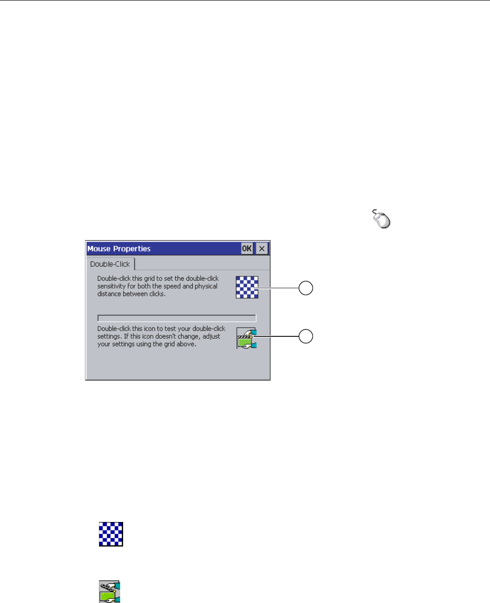
Configuring the operating system
6.4 Changing settings for operation
Mobile Panel 277F IWLAN
Operating Instructions, 12/2007, A5E01003940-01 143
6.4.3 Setting the double-click
Introduction
You can start applications in the Control Panel and in Windows CE by double-clicking.
In the "Mouse Properties" dialog box you can change the following settings.
● The time interval between two clicks for a double-click
● The physical distance between two clicks for a double-click
A double-click corresponds to two brief touches in sequence.
Requirements
You have opened the "Mouse Properties" dialog with the "Mouse" icon.
① Icon for setting the double-click
② Icon for testing the double-click
Procedure
Proceed as follows:
1. Double-click on the grid.
After one double-click the grid is shown in inverse colors.
2. Double-click on the icon.
If the double-click is valid, the icon is displayed as follows:
3. If the icon remains unchanged, double-click on the grid again.
4. Confirm your entries.
The dialog closes.
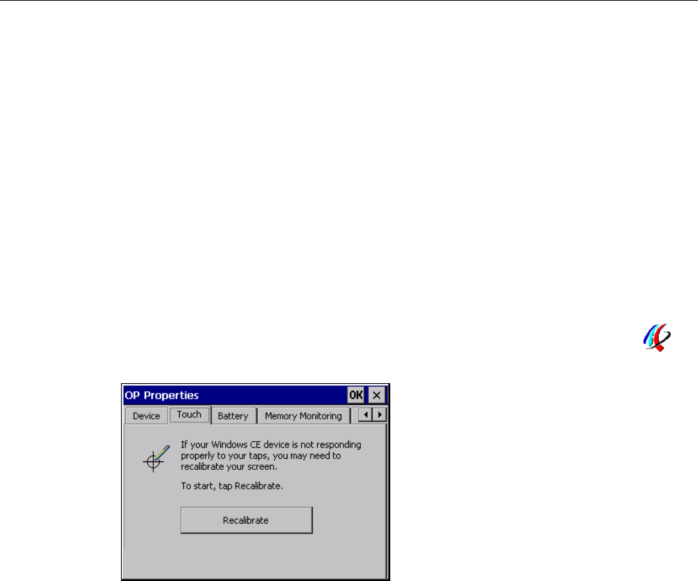
Configuring the operating system
6.4 Changing settings for operation
Mobile Panel 277F IWLAN
144 Operating Instructions, 12/2007, A5E01003940-01
Result
The double-click adjustment is completed.
6.4.4 Calibrating the touch screen
Introduction
Depending on the mounting position and viewing angle, it is possible that parallax may occur
when operating the touch screen. In order to prevent any operating errors as a result,
calibrate the touch screen again in the startup phase or during runtime.
Requirements
You have opened the "OP Properties" dialog box, "Touch" tab, by touching the "OP"
icon.
Procedure
Proceed as follows:
1. Use the "Recalibrate" button to open the following dialog box:
Configuring the operating system
6.4 Changing settings for operation
Mobile Panel 277F IWLAN
Operating Instructions, 12/2007, A5E01003940-01 145
&DUHIXOO\SUHVVDQGEULHIO\KROGVW\OXVRQWKHFHQWHURI
WKHWDUJHW5HSHDWDVWKHWDUJHWPRYHVDURXQGWKHVFUHHQ
1. Briefly touch the center of the calibration crosshairs ①.
The calibration crosshairs is then displayed at four more positions.
2. Touch the middle of the calibration crosshairs for each position.
If you do not touch the middle of the calibration crosshairs, the procedure is repeated.
Once you have touched the calibration crosshairs for all positions, the following dialog
appears:
New calibration settings have been measured.
Tape the screen to register saved data.
Wait for 30 seconds to cancel saved data and
keep the current setting.
Time limit: 30 sec
1. Touch the screen within 30 seconds.
The new calibration is saved. If you wait longer than 30 seconds, the new calibration is
discarded and the original calibration remains in effect.
The "OP Properties" dialog box, "Touch" tab is displayed again.
2. Close the dialog.
Result
The HMI device touch screen is now recalibrated.
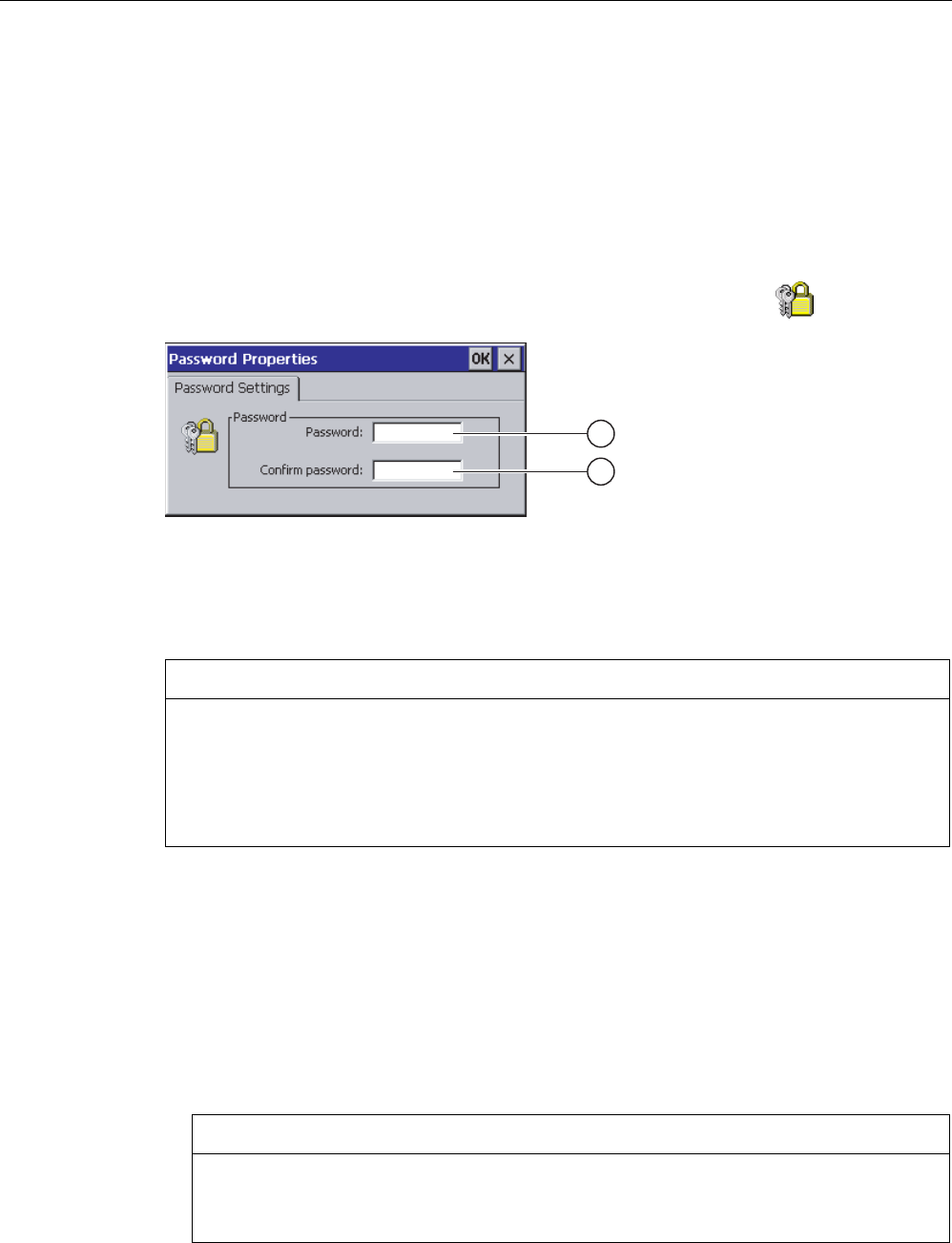
Configuring the operating system
6.5 Changing password protection
Mobile Panel 277F IWLAN
146 Operating Instructions, 12/2007, A5E01003940-01
6.5 Changing password protection
Introduction
You can protect the Control Panel and the Windows CE taskbar with a password.
Requirements
You have opened the "Password Properties" dialog with the "Password" icon.
① Password text box
② Text box for entering the password a second time
NOTICE
If the password is no longer available, you cannot do the following until you have updated
the operating system.
• Making changes to the Control Panel
• Operating the Windows CE task bar
All data on the HMI device will be overwritten when you update the operating system!
Procedure for activating password protection
Proceed as follows:
1. Enter a password in the "Password" text box.
2. Repeat the password entry in the "Confirm password" text box.
3. Confirm your entries.
The dialog closes.
NOTICE
The following characters cannot be used in passwords:
• Blank
• Special characters * ? . % / \ ' "

Configuring the operating system
6.6 Changing HMI device settings
Mobile Panel 277F IWLAN
Operating Instructions, 12/2007, A5E01003940-01 147
Result
You cannot open the Control Panel or Windows CE taskbar without entering a password.
Procedure for deactivating password protection
Proceed as follows:
1. Delete the inputs in the "Password" and "Confirm password" text boxes.
2. Confirm your entries.
The dialog closes.
Result
Password protection for the Control Panel and the Windows CE taskbar is disabled.
6.6 Changing HMI device settings
6.6.1 Setting the date and time
Introduction
You can set the date and time on the HMI device. The HMI must be restarted in the following
cases:
● You have changed the time zone setting
● You have changed the "Daylight savings time currently in effect" check box setting
Requirements
You have opened the "Date/Time Properties" using the "Date/Time Properties" icon.

Configuring the operating system
6.6 Changing HMI device settings
Mobile Panel 277F IWLAN
148 Operating Instructions, 12/2007, A5E01003940-01
① Time zone selection box
② Text box for the time
③ Date selection box
④ "Daylight savings" check box
⑤ Button for applying changes
Procedure
Proceed as follows:
1. Select the appropriate time zone for the HMI device from the "Time Zone" selection box.
2. Touch the "Apply" button to confirm your entry.
The time of day shown in the "Current Time" box is adjusted correspondingly to the
selected time zone.
3. Set the date in the selection box.
4. Set the current time of day in the "Current Time" text box.
5. Touch the "Apply" button to confirm your input.
The values you have set are now in effect.
Note
The system does not automatically switch between winter and summer time.
1. If you want to switch from winter to summer time, select the
"Daylight savings time currently in effect" check box.
When you press the "Apply" button, the time is brought forward by one hour.
2. If you want to switch from summer to winter time, clear the
"Daylight savings time currently in effect" check box.
When you press the "Apply" button, the time is moved backwards by one hour.
3. Confirm your entries.
The dialog closes.
Result
The settings for the data and time of day have now been changed.
Internal clock
The HMI device has an internal buffered clock.
Synchronizing the date and time with the PLC
The date and time of the HMI device can be synchronized with the PLC if this has been
configured in the project and the PLC program.
Additional information on this subject is available in the "WinCC flexible" system manual.
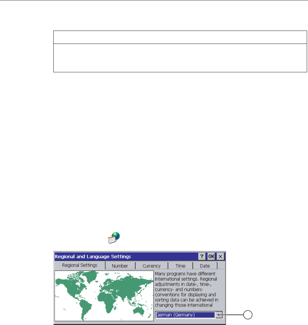
Configuring the operating system
6.6 Changing HMI device settings
Mobile Panel 277F IWLAN
Operating Instructions, 12/2007, A5E01003940-01 149
NOTICE
Time-dependent reactions
You have to synchronize the date and time when time-controlled responses are triggered in
the PLC by the HMI device.
See also
Restarting the HMI device (Page 156)
6.6.2 Changing regional settings
Introduction
In different countries, for example, the date, time and decimal points are displayed
differently. You can adjust the display format to meet the requirements of different regions.
The country-specific settings apply to the current project. If the project language is changed,
the country-specific settings are also changed.
Requirements
You have opened the "Regional and Language Settings" dialog with the
"Regional Settings" icon.
① Region selection box
Procedure
Proceed as follows:
1. Select the region from the selection box.
2. Change to the "Number", "Currency", "Time" and "Date" tabs and set the selection boxes
to the desired settings.
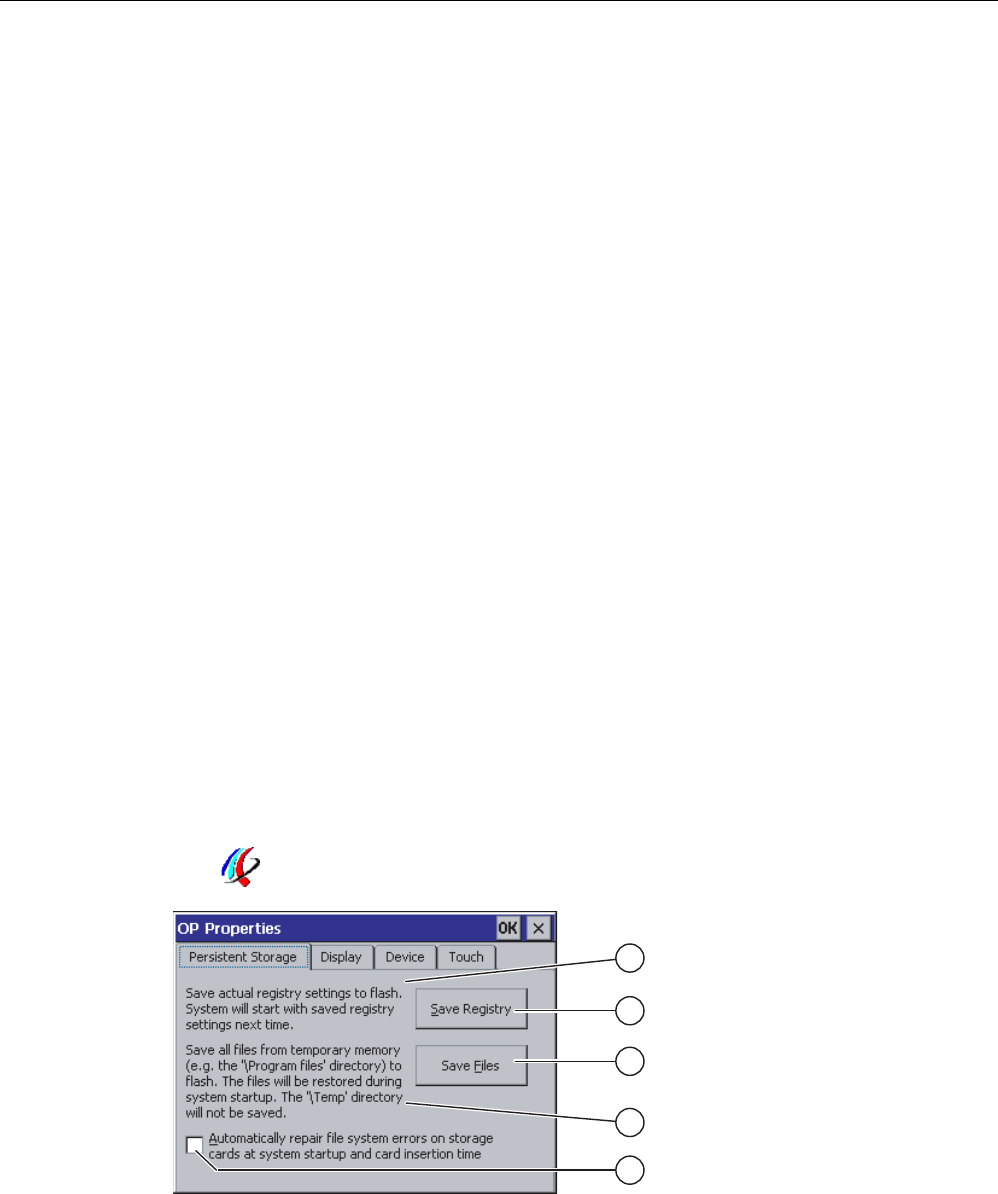
Configuring the operating system
6.6 Changing HMI device settings
Mobile Panel 277F IWLAN
150 Operating Instructions, 12/2007, A5E01003940-01
3. Confirm your entries.
The dialog closes.
Result
The HMI device's regional settings have been changed.
6.6.3 Backup registry information
Registry information and temporary data
You can install and uninstall your own programs on the HMI devices under Windows CE.
You must save the registry settings after installation or uninstallation.
You can save the following data to the flash memory:
● Registry information
● Temporary files
Restoring the file system of a memory card
If memory cards are used, the file system on the memory card may become damaged,
perhaps due to a power failure. The HMI device detects the defective file system on start-up
or when the memory card is inserted. The HMI device can restore the file system
automatically or on request.
Requirements
You have opened the "OP Properties" dialog box, "Persistant Storage" tab, by touching the
"OP" icon.
① Meaning of the text in the dialog:
Saves the current registry information to the flash memory. The HMI device loads the saved
registry information the next time it boots.
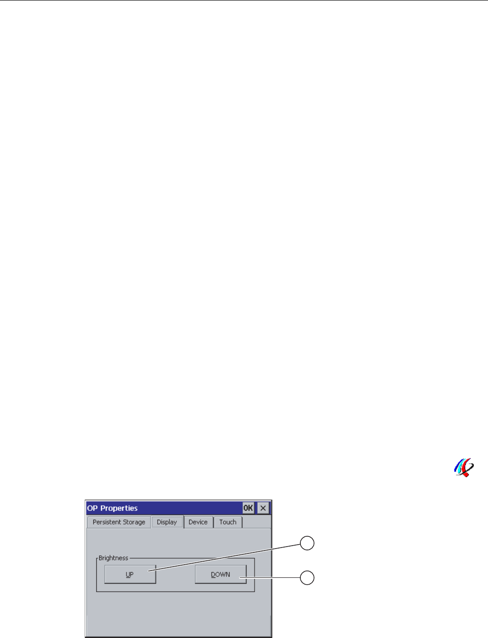
Configuring the operating system
6.6 Changing HMI device settings
Mobile Panel 277F IWLAN
Operating Instructions, 12/2007, A5E01003940-01 151
② Button for saving registry information
③ Button for saving temporary files
④ Meaning of the text in the dialog:
Saves all the files in temporary storage to the flash memory (for example, from the "Program
Files" directory). These files are written back when the HMI device is started. The "\Temp"
directory is not saved.
⑤ Check box for automatically restoring the file system on the memory card when the HMI
device starts up and when a memory card is inserted.
Procedure
Proceed as follows:
1. If you want to save the current registration entries, click the "Save Registry" button.
2. If you want to save the temporary files, click the "Save Files" button.
3. Specify how the file system on the memory card should be restored.
– Activate automatic restore by selecting the "Automatically Repair ..." check box.
– If you only want the restore to be carried out upon prompting, clear the
"Automatically Repair ..." check box.
4. Confirm your entries.
The dialog closes.
Result
The desired data is saved.
6.6.4 Changing screen settings
Requirements
You have opened the "OP Properties" dialog box, "Display" tab, by touching the "OP"
icon.

Configuring the operating system
6.6 Changing HMI device settings
Mobile Panel 277F IWLAN
152 Operating Instructions, 12/2007, A5E01003940-01
① Button for increasing the brightness
② Button for reducing the brightness
Procedure
Proceed as follows:
1. If you want to increase the brightness of the screen, press "UP".
2. If you want to reduce the brightness of the screen, press "DOWN".
3. Confirm your entries.
The dialog closes.
Result
The screen settings have been changed.
6.6.5 Setting the screen saver
Power management settings in the WinCC flexible project
To save power, the HMI device has a power management function with the following states:
● "Power Save 1"
– Reduces the brightness of the backlighting.
● "Power Save 2"
– The touch screen is switched off.
– The function keys are not active.
The relevant time intervals are set in the project. Power management is automatically
activated if the HMI device is not operated within the specified period of time.
You can clear the "Power Save 1" state by touching the touch screen or pressing the
function key.
You can clear the "Power Save 2" state by briefly pressing the ON/OFF button.
Settings in the Control Panel
You can also set the following time intervals in the HMI device Control Panel:
● For the automatic activation of the screen saver
● For the automatic reduction in the screen's backlighting
The screen saver and the reduced screen backlighting functions are switched back off by
means of the following actions:
● By pressing any key
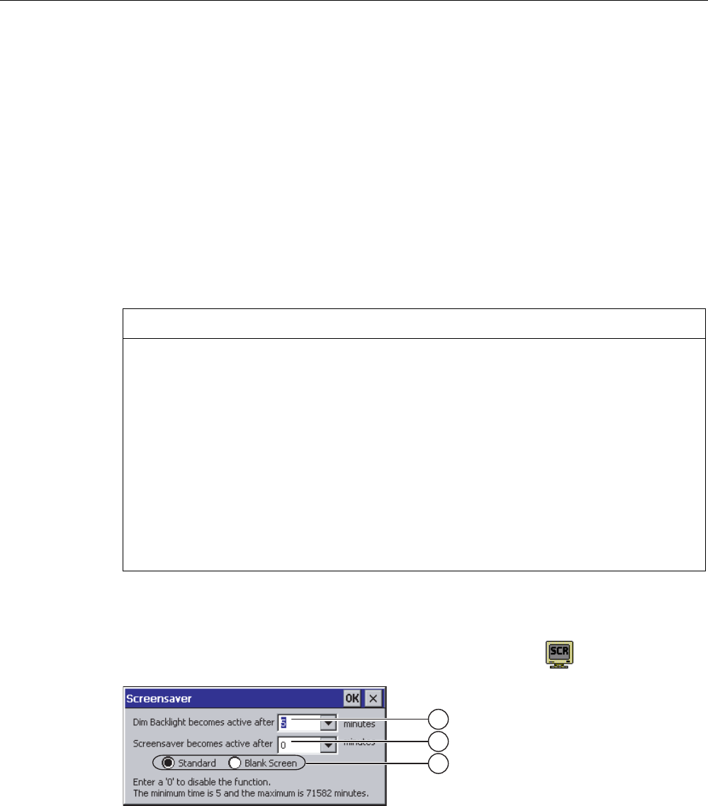
Configuring the operating system
6.6 Changing HMI device settings
Mobile Panel 277F IWLAN
Operating Instructions, 12/2007, A5E01003940-01 153
● By touching the touch screen
The function associated to the key or button will not be executed by this.
Validity
The time until the backlighting is reduced is always the shorter time interval.
In other words,. the time interval set in the "Screensaver" dialog box applies if it is shorter
than the setting for "Power Save 1" in the project.
If a value of "0" is entered in the "Screensaver" dialog box for the reduction in backlighting,
the value set in the project will apply.
After you have selected the screen saver and reduction of the backlighting, you must restart
the HMI device. The settings become effective following a restart.
NOTICE
Reducing the brightness of the backlighting
The brightness of the backlighting decreases incrementally during its operational life. In
order to increase the operational life of the backlighting, activate the backlighting reduction.
Burn-in effect
Screen contents may occasionally leave a burn-in effect in the background if they appear
too long.
This burn-in effect will automatically disappear after a certain amount of time if the
screensaver is activated, for example. The longer the same content is displayed on the
screen, the longer it will take for the burn-in effect to disappear.
Generally, you should always activate the screen saver.
When the screen saver is active, the backlighting is reduced at the same time.
Requirements
You have opened the "Screensaver" dialog with the "ScreenSaver" icon.
① Time interval in minutes until backlighting is reduced
② Period of time in minutes before the screen saver is activated
③ Screen saver setting

Configuring the operating system
6.6 Changing HMI device settings
Mobile Panel 277F IWLAN
154 Operating Instructions, 12/2007, A5E01003940-01
Procedure
Proceed as follows:
1. Enter the interval in minutes after which the backlighting is to be reduced.
Entering "0" will deactivate the backlighting reduction.
2. Enter the number of minutes before the screen saver is to be activated.
The minimum time is 5 minutes and the maximum time is 71582 minutes.
Entering "0" disables the screen saver.
3. Select either the standard screen saver or an empty screen.
– In order to select the standard screen saver, select the "Standard" option.
– In order to select a blank screen as screen saver, select the "Blank Screen" option.
4. Confirm your entries.
The dialog closes.
Result
The screen saver and the reduced backlighting for the HMI device is set. After you have
reselected the screen saver and reduction of the backlighting, you must restart the HMI
device. The selection becomes effective following a restart.
See also
Power management (Page 98)
Restarting the HMI device (Page 156)
6.6.6 Changing the printer properties
Introduction
You can print hardcopies and reports on a network printer. Line printing of alarms is not
possible on a network printer.
The list of current printers and required settings for HMI devices can be found on the Internet
under "http://support.automation.siemens.com/WW/view/en/11376409".
Requirements
You have opened the "Printer Properties" dialog with the "Printer" icon.

Configuring the operating system
6.6 Changing HMI device settings
Mobile Panel 277F IWLAN
Operating Instructions, 12/2007, A5E01003940-01 155
① Selection boxd for the printer
② Interface selection box
③ Network address of the printer
④ Paper format selection box
⑤ "Orientation" group with radio buttons for print orientation
⑥ Print quality check box
⑦ Color printing check box
Procedure
Proceed as follows:
1. Select the printer from the "Printer Language:" selection box.
2. In the "Port:" selection box, select the "Network:" interface.
3. In the "Network:" text box, enter the network address of the printer.
4. Select the paper format from the"Paper Size:" selection box.
5. Select the required radio button in the "Orientation" group:
– "Portrait" for portrait
– "Landscape" for landscape
6. Select the print quality.
– Select the "Draft Mode" check box if you wish to print in draft mode.
– Clear the "Draft Mode" check box if you wish to print with higher quality.
7. If the printer selected can print in color and you wish it to do so, select the "Color" check
box.
8. Confirm your entries.
The dialog closes.
Result
The settings for the printer have now been changed.
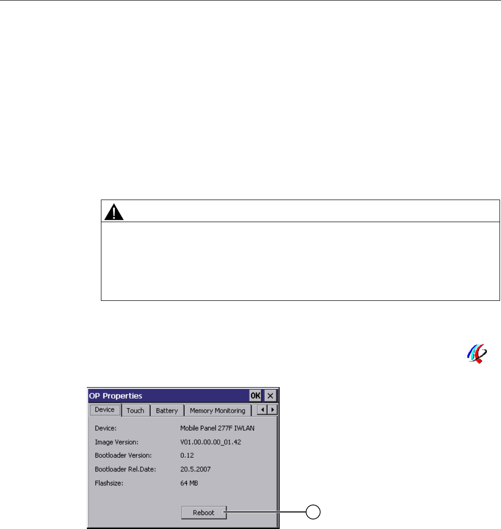
Configuring the operating system
6.6 Changing HMI device settings
Mobile Panel 277F IWLAN
156 Operating Instructions, 12/2007, A5E01003940-01
6.6.7 Restarting the HMI device
Introduction
The HMI device must be restarted in the following cases:
● You have activated or deactivated the PROFINET IO direct keys.
● You have changed the time zone setting
● You have switched between summer time and winter time.
● You have reselected the screen saver and reduction of the backlighting.
● You have changed the transfer rate to the Access Point.
CAUTION
Data loss when the HMI device is restarted
All volatile data is lost when the HMI device is restarted.
Check the following:
• The project on the HMI device is complete
• No data is being written to the flash memory
Requirements
You have opened the "OP Properties" dialog box , "Device" tab, by touching the "OP"
icon.
① Button for restarting the HMI device
Procedure
1. Press "Reboot" to reboot the HMI device.
A warning is displayed.
Confirm this warning to execute the following:
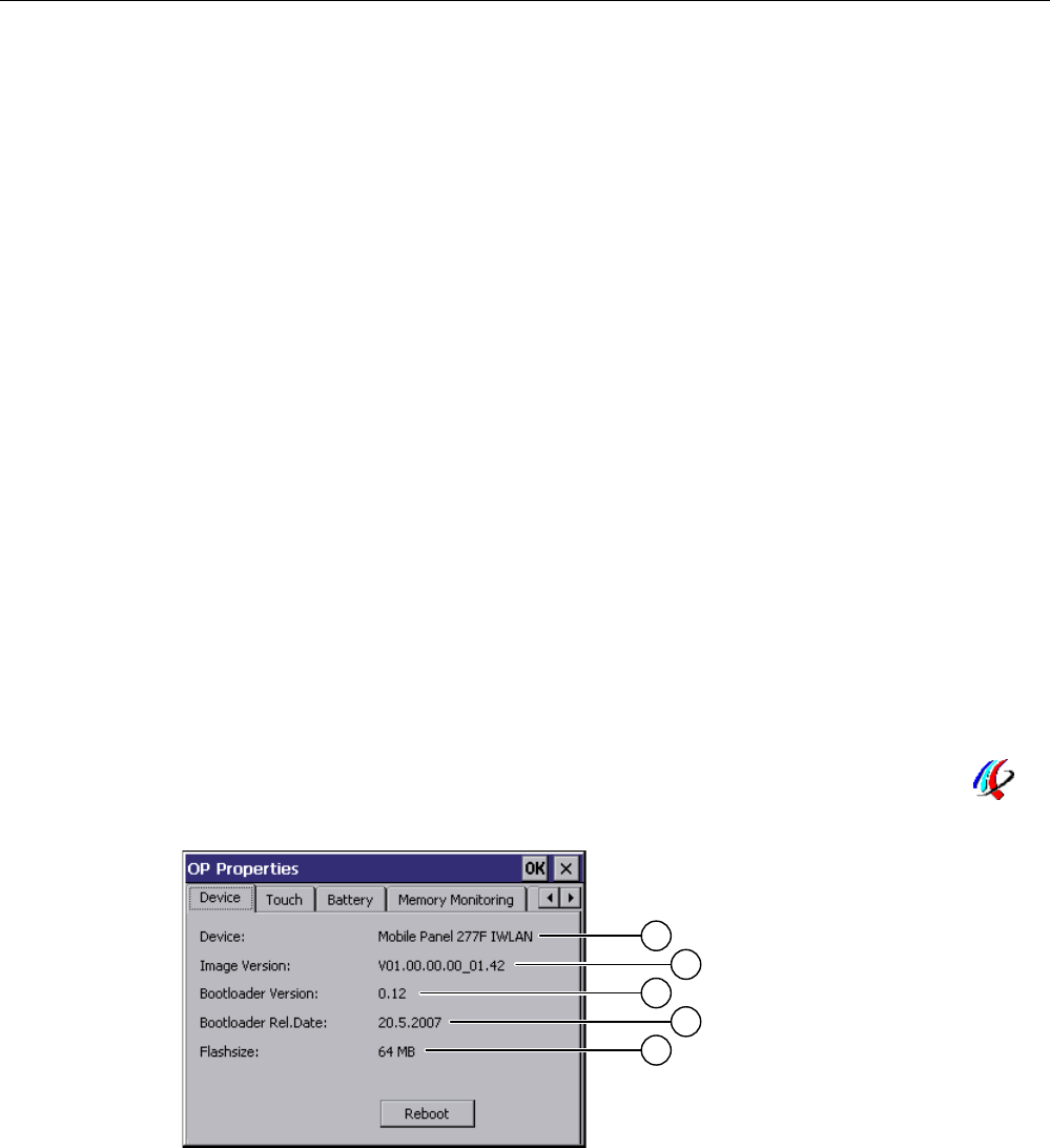
Configuring the operating system
6.6 Changing HMI device settings
Mobile Panel 277F IWLAN
Operating Instructions, 12/2007, A5E01003940-01 157
– If no projects are active on the HMI device, it will restart immediately.
– If a project is active on the HMI device, it will output several prompts. After you have
acknowledged these prompts, the HMI device will restart.
Result
The HMI device starts.
See also
Setting the date and time (Page 147)
Enabling PROFINET IO (Page 165)
Overview (Page 128)
6.6.8 Displaying information about the HMI device
Introduction
You will need the device-specific information if you contact A&D Technical Support.
Requirements
You have opened the "OP Properties" dialog box, "Device" tab, by touching the "OP"
icon.
① HMI device name
② Version of the HMI device image
③ Version of the boot loader
④ Boot loader release date
⑤ Size of the internal flash memory in which the HMI device image and project are stored
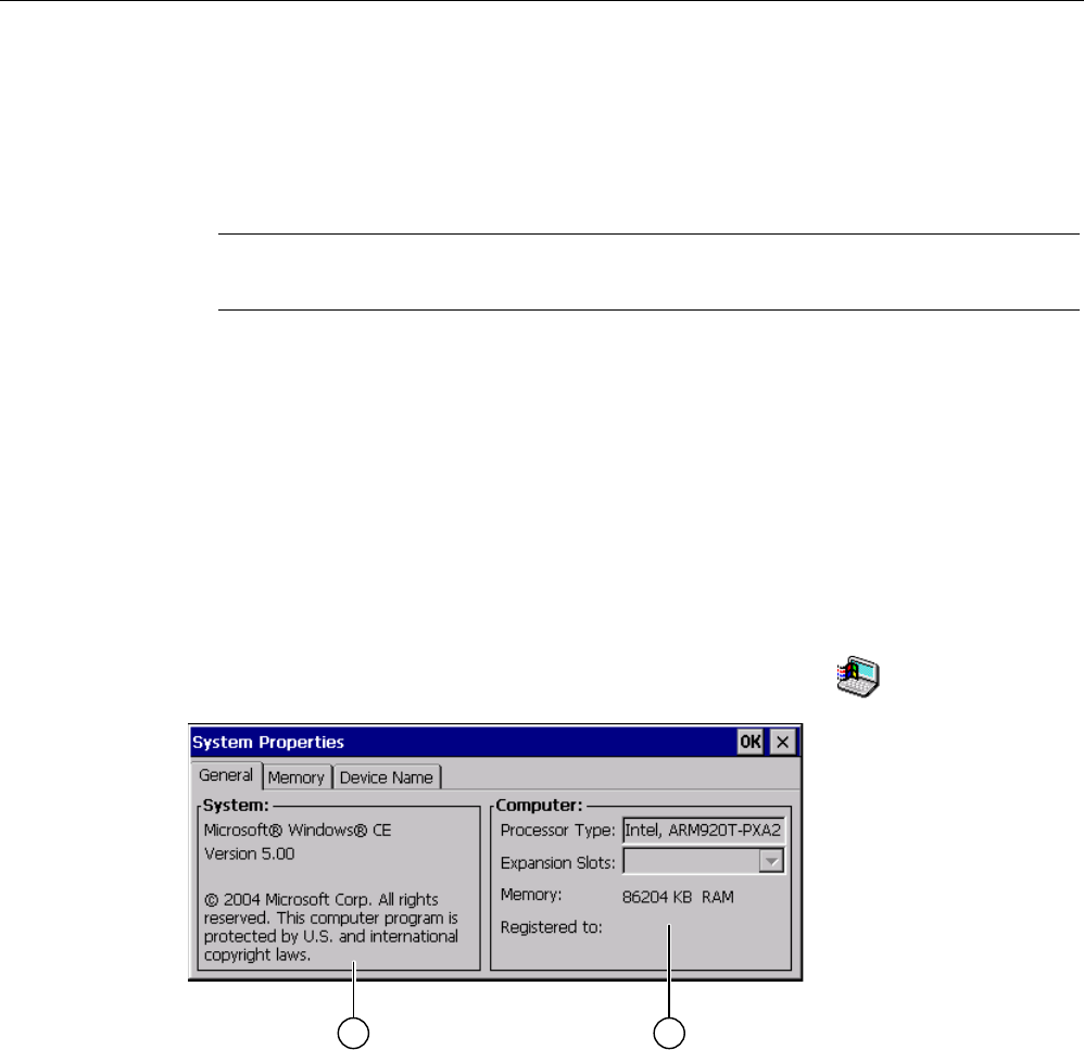
Configuring the operating system
6.6 Changing HMI device settings
Mobile Panel 277F IWLAN
158 Operating Instructions, 12/2007, A5E01003940-01
Procedure
Proceed as follows:
1. The device-specific information is displayed in the "Device" tab.
2. Close the dialog when the information is no longer required.
Note
The memory available for the project is only a part of the internal flash memory displayed.
6.6.9 Displaying system properties
Introduction
The system-specific information provides you with information about the processor,
operating system and memory of the HMI device.
Requirements
You have opened the "System Properties" dialog with the "System" icon.
① Copyright for Microsoft Windows CE
② Information about the processor, size of the internal flash memory, and capacity of a memory
card when inserted
Displaying system properties
The system information is displayed. This dialog is read-only.
Close the dialog.
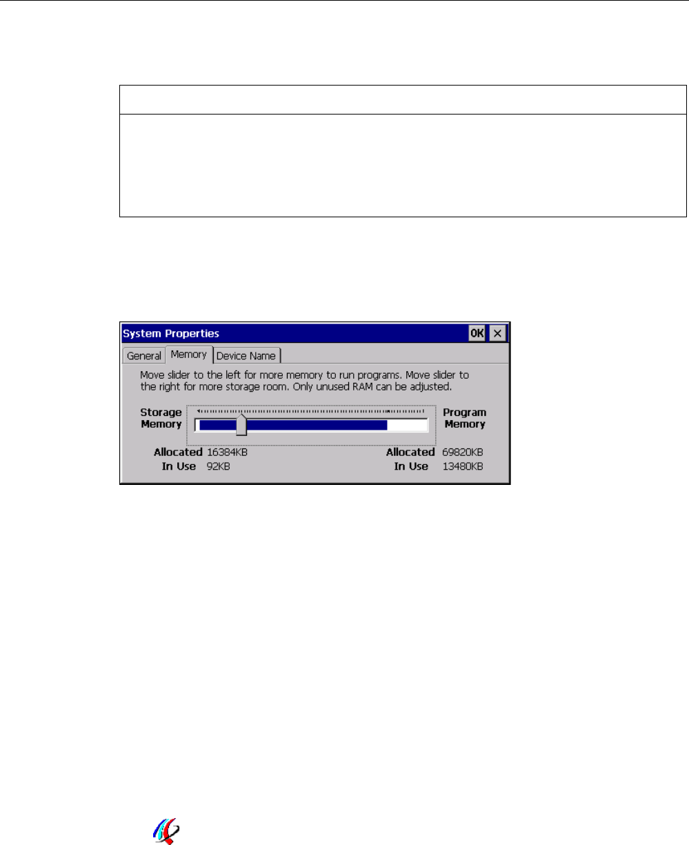
Configuring the operating system
6.6 Changing HMI device settings
Mobile Panel 277F IWLAN
Operating Instructions, 12/2007, A5E01003940-01 159
Procedure for displaying memory information
NOTICE
"Memory" tab
Do not change the memory distribution in the "Memory" tab.
Only applies for the usage of options:
An alteration to the memory distribution may be necessary. Please refer to the
accompanying documentation for the option for additional information.
Proceed as follows:
1. Change to the "Memory" tab.
The memory information is displayed.
1. Close the dialog.
6.6.10 Activating vibration alarm
Introduction
You can activate a vibration alarm for the HMI device. The vibration alarm will be triggered in
the current project under the following circumstances:
● You leave the effective range with the HMI device without logging the HMI device off from
the effective range.
● The charging status of the main battery is critical.
Requirements
You have opened the "OP Properties" dialog box, "Vibration Alarm" tab, by touching the
"OP" icon.
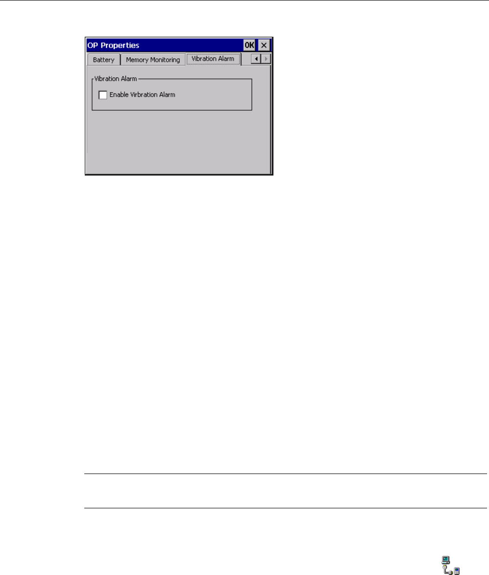
Configuring the operating system
6.7 Programming the data channel
Mobile Panel 277F IWLAN
160 Operating Instructions, 12/2007, A5E01003940-01
Procedure
1. Select the "Enable Vibration Alarm" check box.
2. Confirm your entries.
The dialog closes.
Result
The vibration alarm is activated.
6.7 Programming the data channel
Introduction
You can only transfer a project if you have enabled at least one data channel.
If you block all data channels, the HMI device is protected against unintentional overwriting
of the project data and HMI device image.
Note
Data channel 1 is not available with the Mobile Panel 277 Wireless.
Requirements
The "Transfer Settings" dialog box has been opened using the "Transfer Settings" icon.
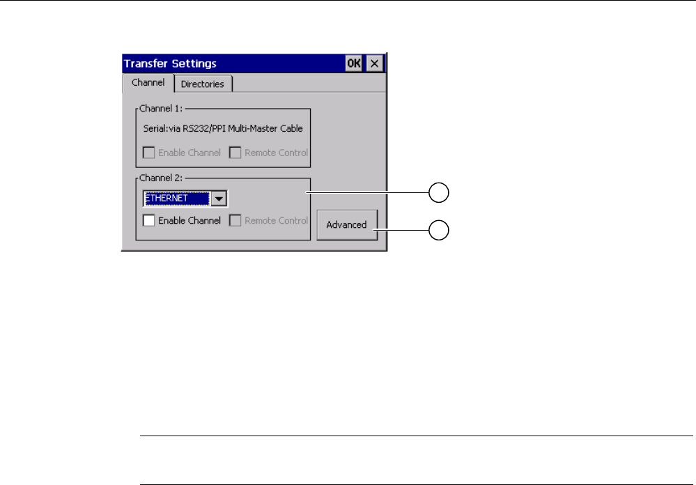
Configuring the operating system
6.7 Programming the data channel
Mobile Panel 277F IWLAN
Operating Instructions, 12/2007, A5E01003940-01 161
① Group for the data channel 2 (Channel 2)
② Button for the "Network and Dial-Up Connections" dialog box
Procedure
Proceed as follows:
1. Select the desired interface from the selection box.
Note
"ETHERNET" is for communication via LAN and WLAN.
1. If you want to enable the data channel, select the "Enable Channel" check box.
2. If you want to disable the data channel, clear the "Enable Channel" check box.
3. If you want to enable automatic transfer, select the "Remote Control" check box.
4. Enter further parameters if required.
– Applies to "ETHERNET"
Press "Advanced" to change to "Network and Dial-Up Connections".
Open the "LAN"or "WLAN" entry. You can change the TCP/IP settings there.
Confirm your entries.
Close "Network and Dial-Up Connections".
– Applies to "USB"
No further settings are required for "USB".
5. Confirm your entries.
The dialog closes.
Result
The data channel is programmed.

Configuring the operating system
6.8 Setting the delay time
Mobile Panel 277F IWLAN
162 Operating Instructions, 12/2007, A5E01003940-01
General information
Note
Changes during "Transfer" mode
If changes are made to the transfer settings when the HMI device is in "Transfer" mode or
while a project is running, the new settings will only take effect the next time a transfer or the
project is started.
This may occur if the Control Panel is opened to change the transfer properties in an active
project.
NOTICE
Transfer mode via channel 2
You can change the settings for the transfer.
The following steps are required:
• Close the project.
• Change the settings on the HMI device.
• Then return to "Transfer" mode.
See also
Changing the network configuration (Page 169)
6.8 Setting the delay time
Introduction
The project is opened following a delay time when the HMI device is switched on. The
Loader is displayed during the delay time.
Requirements
You have opened the "Transfer Settings" dialog box, "Directories" tab, by touching the
"Transfer" icon.
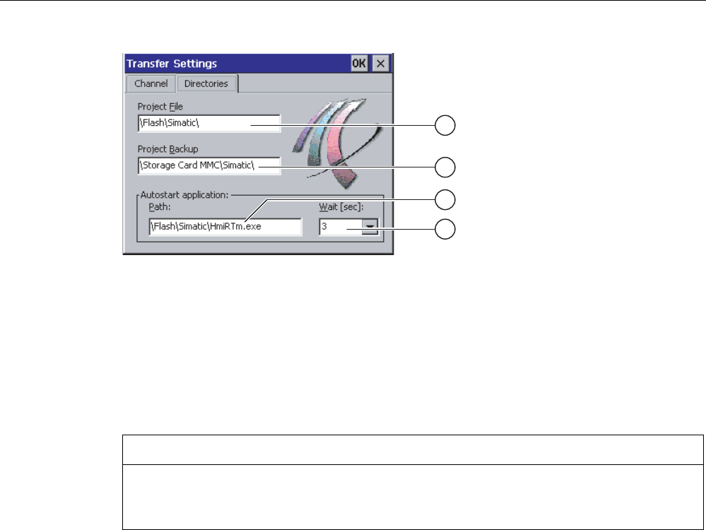
Configuring the operating system
6.8 Setting the delay time
Mobile Panel 277F IWLAN
Operating Instructions, 12/2007, A5E01003940-01 163
① Directory where the project file is saved
② Directory where the compressed source file of your project is saved
The external memory card or the network connection can be defined as the storage location.
During the next backup process, the project's source file is stored in the specified location.
③ Memory location and start file of the HMI device for the executable project file
④ Delay time selection box
NOTICE
Settings under "Project File" and "Path"
Do not change the setting in the "Project File" and "Path:" boxes. The project may not open
at the next start of the HMI device if changes are made here.
Procedure for setting the delay time
1. Select the desired delay time in seconds from the "Wait [sec]:" selection box.
With the value "0", the project starts immediately. It is now no longer possible to call the
Loader after switching on the HMI device. If you still do need to access the Loader an
operating element must be configured to close the project.
2. Confirm your entries.
The dialog closes.
Result
The delay time for the HMI device is now set.

Configuring the operating system
6.9 Setting the PROFIsafe address
Mobile Panel 277F IWLAN
164 Operating Instructions, 12/2007, A5E01003940-01
6.9 Setting the PROFIsafe address
PROFIsafe address
Each participant in PROFIsafe communication has a unique PROFIsafe address. This
address is used to send safety message frames between the Mobile Panel 277F IWLAN and
the F CPU.
Note
Assign the HMI device a PROFIsafe address that is unique within the relevant network
segment.
Validity of the PROFIsafe address
The PROFIsafe address can be parameterized at the following stages:
● In the HMI device Control Panel
● In the WinCC flexible project
The PROFIsafe address that the HMI device loads depends on the parameterization in the
Control Panel.
● If a valid PROFIsafe address has been parameterized in the Control Panel:
The HMI device loads the PROFIsafe address set in the Control Panel.
● If a valid PROFIsafe address has not been parameterized in the Control Panel:
The HMI device loads the PROFIsafe address set in the project.
Note
The invalid address 65,535 is parameterized by default in the Control Panel of the HMI
device. The HMI device loads the address set in the project.
NOTICE
No integration in PROFIsafe communication
To ensure that the HMI device can be integrated in PROFIsafe communication, the
following addresses must match:
• The PROFIsafe address configured in HW Config by STEP 7
• The PROFIsafe address set in the "PROFIsafe" dialog box
Requirements
You have opened the "PROFIsafe" dialog with the "PROFIsafe" icon.