Siemens 277IWLAN-V100 Mobile Panel 277 IWLAN User Manual Mobile Panel 277F IWLAN
Siemens AG Mobile Panel 277 IWLAN Mobile Panel 277F IWLAN
Siemens >
Contents
UserMan2
Configuring the operating system
6.10 Enabling PROFINET IO
Mobile Panel 277F IWLAN
Operating Instructions, 12/2007, A5E01003940-01 165
Procedure
Proceed as follows:
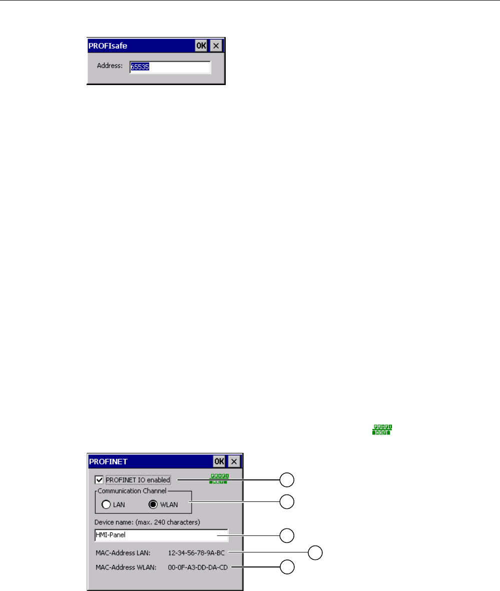
1. If you wish the HMI device to load the PROFIsafe address set in the Control Panel, enter
a value between 1 and 65,534 in the "Address:" text box.
2. If you wish the HMI device to load the PROFIsafe address set in the project, enter a value
between the invalid PROFIsafe address 65,535 in the "Address:" text box.
Result
The PROFIsafe address is set.
6.10 Enabling PROFINET IO
PROFINET IO
Function keys or buttons can be configured as PROFINET IO direct keys. If PROFINET IO
direct keys are used in the project, they must be enabled.
Requirements
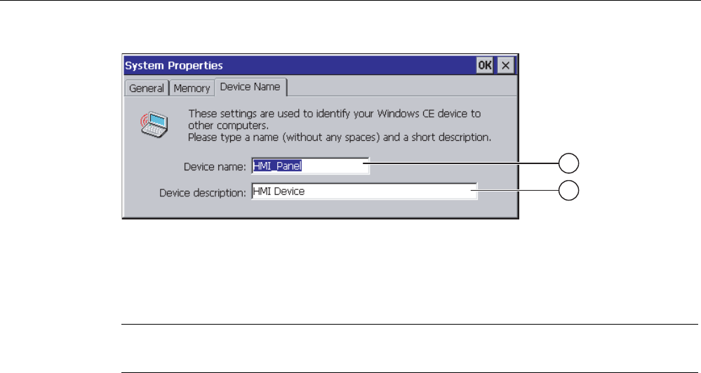
You have opened the "PROFINET" dialog with the "PROFINET" icon.
① Check box to enable or block PROFINET IO direct keys
② Group for communications link
③ Text box for the device name

Configuring the operating system
6.10 Enabling PROFINET IO
Mobile Panel 277F IWLAN
166 Operating Instructions, 12/2007, A5E01003940-01
④ MAC address of the LAN interface
⑤ MAC address of the WLAN interface
Procedure
1. To enable PROFINET IO direct keys, select the "PROFINET IO enabled" check box.
2. Select the communications link.
Note
Select "LAN" for service purposes only. If you select "LAN", the HMI device is connected
directly to the network via the RJ45 interface.
If you connect the configuring PC directly to the HMI device through the RJ45 interface,
you must open the connection compartment. If the connection bay is open, degree of
protection IP 65 is not fulfilled.
1. Enter the device name of the HMI device.
The device name can have a maximum of 240 characters.
NOTICE
Addressing error of PROFINET IO device
The device name does not correspond to the computer name in Windows CE.
The device name must match the device name entered in the HW Config of STEP 7.
1. Confirm your entries.
The dialog closes.
2. Reboot the HMI device after saving the settings.
Result
The PROFINET IO direct keys are enabled.
See also
Restarting the HMI device (Page 156)
Direct keys (Page 234)
Required properties of the WLAN connection (Page 57)

Configuring the operating system
6.11 Configuring network operation
Mobile Panel 277F IWLAN
Operating Instructions, 12/2007, A5E01003940-01 167
6.11 Configuring network operation
6.11.1 Overview of network operation
Introduction
You connect the HMI device to a PROFINET network.
The connection to a network offers, for example, the following options:
● Printing via a network printer
● Saving, exporting and importing of recipe data records on or from a server
● Setting up of message and data archives
● Transferring a project
● Saving data
NOTICE
The HMI device can only be used in PROFINET networks.
The HMI device only has client functionality in the PC network. This means that users
can access files of a node with TCP/IP server functionality from the HMI device via the
network. However, you cannot, for example, access data on the HMI device from a PC
via the network.
Note
Information on communication using SIMATIC S7 via PROFINET is provided in the
"WinCC flexible communication" user manual.
Addressing
Within a PROFINET network, computers are usually addressed using device names. These
device names are translated from a DNS or WINS server to TCP/IP addresses.
The corresponding servers are generally available in PROFINET networks.
Note
The use of TCP/IP addresses to address PCs is not supported by the HMI device's operating
system.
So to address the HMI device using device names in a PROFINET network, you need a
DNS or WINS server.
Consult your network administrator if you have questions in this regard

Configuring the operating system
6.11 Configuring network operation
Mobile Panel 277F IWLAN
168 Operating Instructions, 12/2007, A5E01003940-01
Printing via a network printer
The HMI device's operating system does not support line by line alarm logging via a network
printer. All other printing functions, for example hardcopy or logs are available without
restriction via the network.
Preparation
Before beginning the configuration, request the following network parameters from your
network administrator.
● Does the network use DHCP for dynamic assignment of network addresses?
If not, get a new TCP/IP network address for the HMI device.
● Which TCP/IP address does the default gateway have?
● If a DNS network is used, what are the addresses of the name server?
● If a WINS network is used, what are the addresses of the name server?
General procedure for configuring the network
The HMI device must be configured prior to network operation. The configuration is basically
divided into the following steps:
Proceed as follows:
1. Enter the device name of the HMI device.
2. Configure the network address.
3. Set the logon information.
4. Save the settings.
6.11.2 Setting the device name of the HMI device
Introduction
The HMI device uses the device name to identify itself in the network.
Requirements
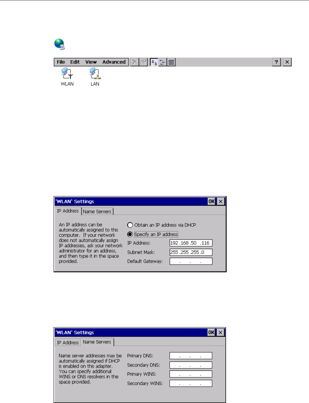
You have opened the "System Properties" dialog with the "System" icon.
Configuring the operating system
6.11 Configuring network operation
Mobile Panel 277F IWLAN
Operating Instructions, 12/2007, A5E01003940-01 169
① Device name of the HMI device
② Description for the HMI device (optional)
Note
To activate the network functions, enter a unique device name in the Device name text box.
Procedure
Proceed as follows:
1. Enter the device name for the HMI device in the "Device name:" text box.
2. If necessary, enter a description for the HMI device in the "Device description:" text box.
3. Confirm your entries.
The dialog closes.
Result
The device name for the HMI device is now set.
See also
Overview of network operation (Page 167)
6.11.3 Changing the network configuration
Introduction
You can change the network settings for the WLAN and LAN connection under "Network and
Dial-Up Connections".
Configuring the operating system
6.11 Configuring network operation
Mobile Panel 277F IWLAN
170 Operating Instructions, 12/2007, A5E01003940-01
Requirements for changing WLAN or LAN connection settings
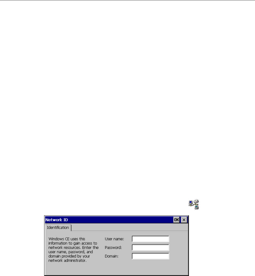
You have opened the following display by touching the "Network and Dial-Up Connections"
icon.
You can enter the connection parameters for the WLAN and LAN connection. The
parameterization is identical.
Procedure for setting the connection parameters
The following procedure shows how to set the connection parameters using the WLAN
connection.
Proceed as follows:
1. Open the "WLAN" entry.
– The "''WLAN' Settings" dialog box opens.
1. Select either automatic address assignment via DHCP or manual address assignment.
2. If you assign the address manually, enter the corresponding addresses in the text boxes
for "IP Address", "Subnet Mask" and, if used, "Default Gateway".
3. If a name server is used in the network, change to the "Name Servers" tab.
Configuring the operating system
6.11 Configuring network operation
Mobile Panel 277F IWLAN
Operating Instructions, 12/2007, A5E01003940-01 171
1. Enter the appropriate addresses.
2. Confirm your entries.
The dialog closes.
3. Close the "Network and Dial-Up Connections" display.
The Control Panel is displayed again.
Result
The WLAN / LAN connection parameters for the HMI device have been set.
See also
Overview of network operation (Page 167)
6.11.4 Changing the logon data
Introduction
In order to access certain network resources you need to log on to the network as a user.
Your administrator will issue you with a user name and password and the name of the
domain.
Requirements
You have opened the "Network ID" dialog with the "Network ID" icon.
Procedure
Proceed as follows:
1. Enter the user name in the "User name" text box.
2. Enter your password in the "Password" text box.
3. Enter the domain name in the "Domain" text box.
Configuring the operating system
6.11 Configuring network operation
Mobile Panel 277F IWLAN
172 Operating Instructions, 12/2007, A5E01003940-01
4. Confirm your entries.
The dialog closes.
Result
The logon data has now been set.
See also
Overview of network operation (Page 167)
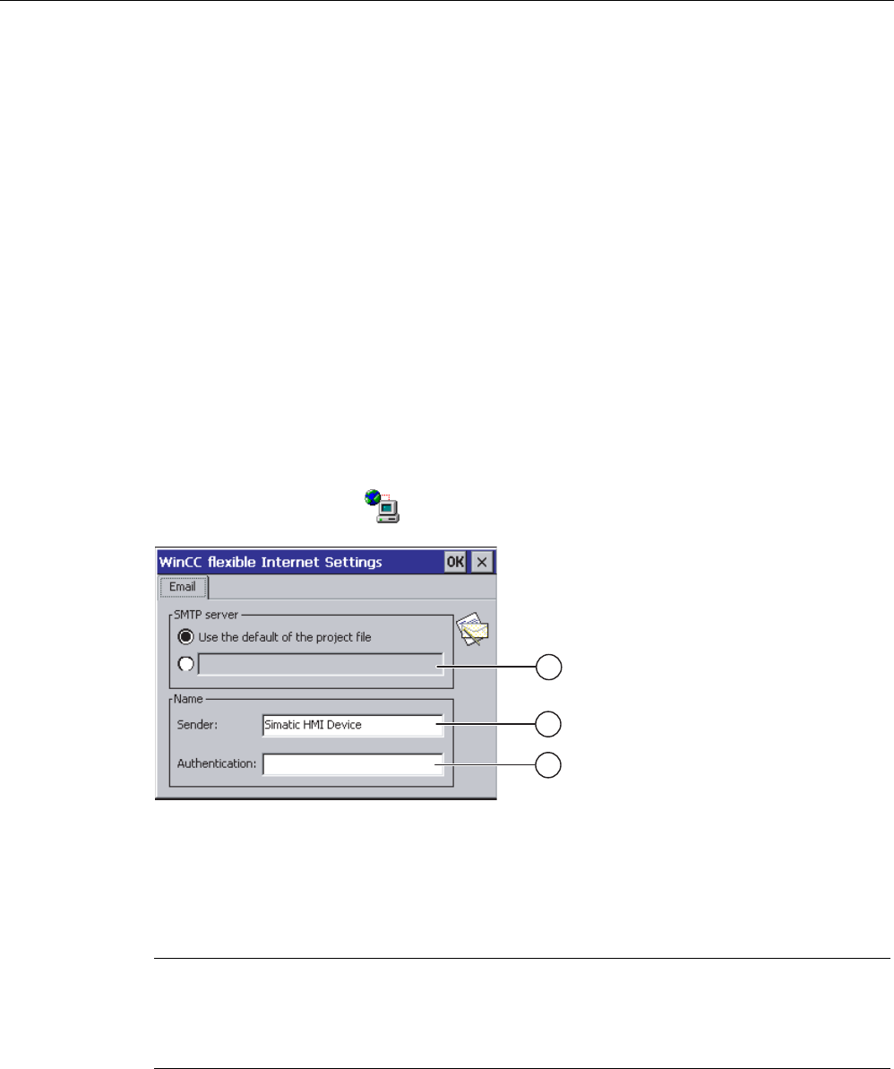
6.11.5 Changing e-mail settings
Requirements
You have opened the "WinCC flexible Internet Settings" dialog with the
"WinCC Internet Settings" icon.
① Setting the SMTP server
② Name for the sender
③ E-mail account
Note
Options
Additional tabs may appear in the "WinCC flexible Internet Settings" dialog. This depends on
the options that have been enabled for network operation in the project.
Procedure for changing e-mail settings
Proceed as follows:
Configuring the operating system
6.12 Changing internet settings
Mobile Panel 277F IWLAN
Operating Instructions, 12/2007, A5E01003940-01 173
1. Specify the SMTP server.
– Select the "Use the default of the project file" option button if you want to use the
SMTP server configured in the project.
– Clear the "Use the default of the project file" option button if you do not want to use the
SMTP server configured in the project. Specify the required SMTP server.
2. Enter the name for the sender in the "Sender" text box.
3. Enter the e-mail account for your e-mail in the "Authentication:" text box.
Some e-mail providers only allow you to send mail if you specify the e-mail account. The
"Authentication:" text box can remain empty if your e-mail provider allows you to send
mail without checking the account.
4. Confirm your entries.
The dialog closes.
Result
The e-mail settings have been changed.
See also
Overview of network operation (Page 167)
6.12 Changing internet settings
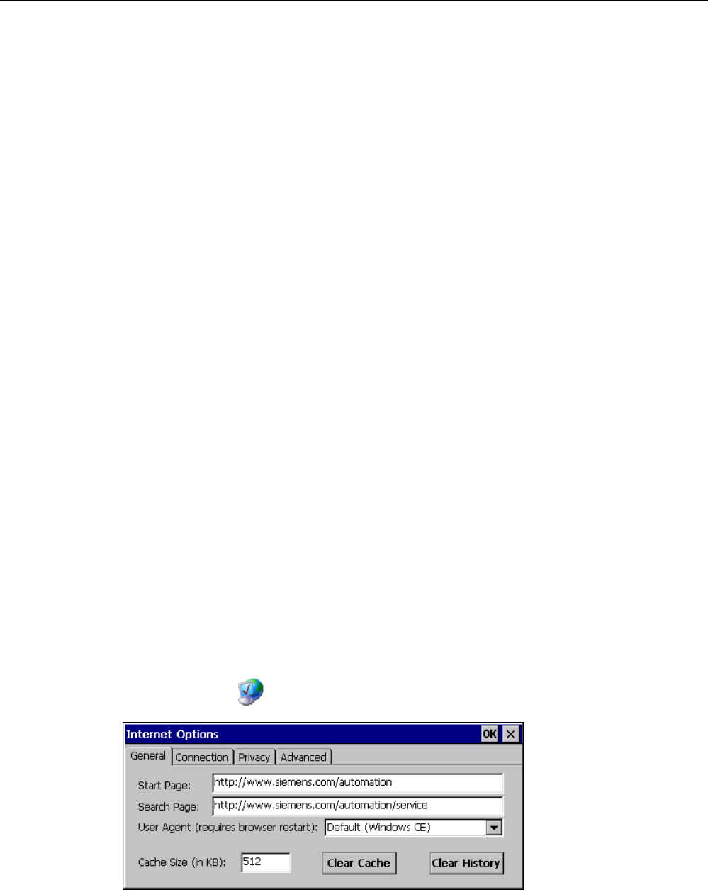
6.12.1 Changing internet settings
Requirements
You have opened the "Internet Options" dialog box, "General" tab, by touching the
"Internet Options" icon.
Configuring the operating system
6.12 Changing internet settings
Mobile Panel 277F IWLAN
174 Operating Instructions, 12/2007, A5E01003940-01
Note
Do not change the settings in the "User Agent" box.
Procedure
Proceed as follows:
1. Enter the homepage for the Internet browser in the "Start Page" text box.
2. Enter the address of the required search engine in the "Search Page" text box.
3. Enter the required cache memory size in the "Cache" text box.
4. If you want to delete the cache memory, press the "Clear Cache" button.
5. If you want to delete the history, press the "Clear History" button.
6. Confirm your entries.
The dialog closes.
Result
The general parameters for the Internet browser have been set.
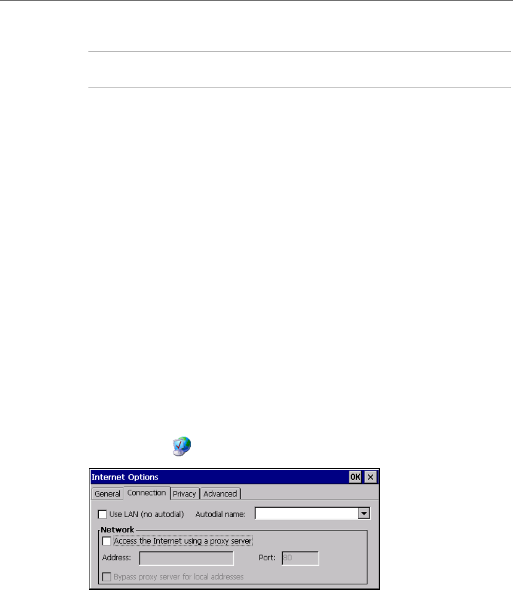
6.12.2 Setting the proxy server
Requirements
You have opened the "Internet Options" dialog box, "Connection" tab, by touching the
"Internet Options" icon.
Procedure
Proceed as follows:
1. Select the "Use LAN (no autodial)" check box.
Configuring the operating system
6.12 Changing internet settings
Mobile Panel 277F IWLAN
Operating Instructions, 12/2007, A5E01003940-01 175
2. If you are using a proxy server, in the "Network" group, select the
"Access the Internet using a proxy server" check box.
Specify the address of the proxy server and the interface.
3. If you want to bypass the proxy server for local addresses, select the
"Bypass proxy server for local addresses" check box.
4. Confirm your entries.
The dialog closes.
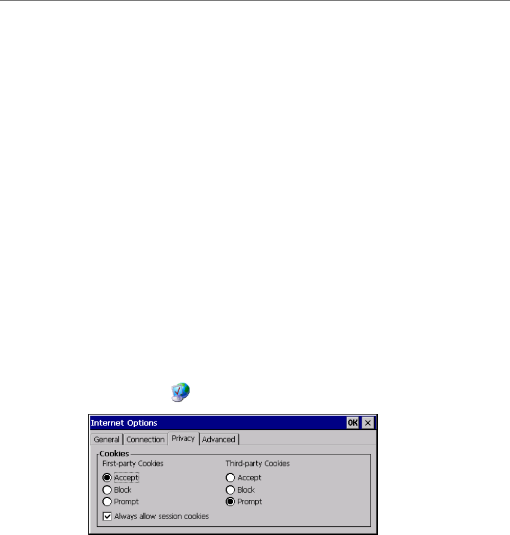
6.12.3 Changing data protection settings
Cookies and encryption
Cookies are pieces of information sent by a web server to a browser. In the event of
subsequent access to the web server, the cookies are sent back. This enables information to
be stored between the accesses.
In order to ensure a high level of privacy, data are sent via the Internet in encrypted form.
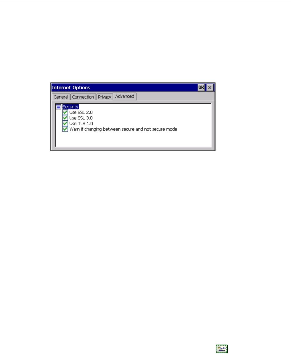
Common encryption protocols include SSL and TLS. You can activate or deactivate the
usage of encryption protocols.
The required settings can be obtained from your network administrator.
Requirements
You have opened the "Internet Options" dialog box, "Privacy" tab, by touching the
"Internet Options" icon.
Procedure
Proceed as follows:
1. Select the required cookie behavior by means of the radio buttons.
– "Accept"
Cookies are stored without request.
– "Block"
Configuring the operating system
6.12 Changing internet settings
Mobile Panel 277F IWLAN
176 Operating Instructions, 12/2007, A5E01003940-01
Cookies will not be stored.
– "Prompt"
Cookies will be stored on request.
2. If you want allow cookies which are restricted to a single session, select the
"Always allow session cookies" check box.
3. Change to the "Advanced" tab.
1. Activate the required encryption protocol.
2. Confirm your entries.
The dialog closes.
Result
The safety settings have now been set.
6.12.4 Importing and deleting certificates
Overview
You can import, view and delete certificates. The certificates differ in the following ways:
● Certificates that you trust
● Own certificates
● Other certificates
The required settings can be obtained from your network administrator.
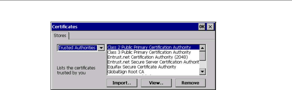
Requirements
You have opened the "Certificates" dialog with the "Certificates" icon.
Configuring the operating system
6.13 Backing up and restoring with an external memory medium
Mobile Panel 277F IWLAN
Operating Instructions, 12/2007, A5E01003940-01 177
Procedure
Proceed as follows:
1. Select the type of certificate from the selection box:
– "Trusted Authorities"
– "My Certificates"
– "Other Certificates"
2. If required, start the importing process with the "Import.." button.
A dialog with source details will open.
3. If required, delete the certificate.
– Mark the desired certificate.
– Delete the selected certificate using the "Remove" button.
4. The "View.." button enables you to list the properties of the selected certificate.
5. Close the dialog.
Result
The changes to the certificates have been carried out.
6.13 Backing up and restoring with an external memory medium
Backup
During a backup, the following data is copied from the HMI device's internal flash memory to
an external memory medium.
● Operating system
● Applications
● Data
The following external storage devices are possible:
Configuring the operating system
6.13 Backing up and restoring with an external memory medium
Mobile Panel 277F IWLAN
178 Operating Instructions, 12/2007, A5E01003940-01
● Memory card
● USB memory stick
CAUTION
IP65 degree of protection not fulfilled
To insert or remove the memory card, you must open the HMI device's connection
compartment. If the connection bay is open, degree of protection IP 65 is not fulfilled.
It is preferable to back up onto a USB memory stick.
Requirements for backup
● The current project and all other applications are closed, except Control Panel.
● The HMI device features an external storage device with sufficient free space.
The size of the internal flash memory is displayed with information about the HMI device.
If the available space on the external memory medium is insufficient, a warning is
displayed and backup is aborted.
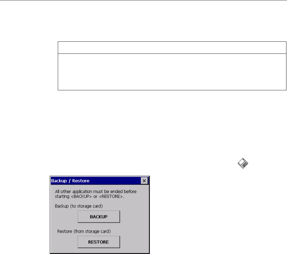
You have opened the "Backup/Restore" dialog with the "Backup/Restore" icon.
Procedure for backup
Proceed as follows:
1. Select "BACKUP" to start Backup.
The HMI device checks the external memory.
The HMI device issues messages in the following situations:
– More than one external memory is available:
Select the desired memory.
– The external memory is not available or is defective:
Acknowledge the displayed messages.
The Control Panel is displayed again.
Replace the external memory. Start the backup process again.

Configuring the operating system
6.13 Backing up and restoring with an external memory medium
Mobile Panel 277F IWLAN
Operating Instructions, 12/2007, A5E01003940-01 179
– Data is already stored on the external memory.
2. Follow the instructions of the HMI device.
The following messages are displayed in sequence during backup:
– "Checking Registry"
– "Backup Progress"
– "Saving CE-Image"
A progress bar shows the status of the backup process.
If backup was successful, the following message is displayed:
"Backup successfully completed. Press OK and remove your storage card."
3. Click "OK" button to acknowledge the message.
Remove the external memory medium.
Result
The HMI device data is now saved on the external memory.
Requirements for restoring
The HMI device features an external memory medium that stores the backup.
Procedure for restoring
NOTICE
Deleting the flash memory
A restore operation deletes the old data from flash memory of the HMI device on
confirmation. The data stored on the external memory is then copied to the internal flash
memory. Existing license keys are deleted following your confirmation.
The restore process involves the following steps:
● The Windows CE image is restored.
● The HMI device starts.
● All other data is restored.
NOTICE
Cancel restore
If the external memory is removed during the restore process, the process is canceled.
Ensure that the external memory is not removed at any point during the restore process.
Proceed as follows:
1. Select "RESTORE" to start Restore.

Configuring the operating system
6.13 Backing up and restoring with an external memory medium
Mobile Panel 277F IWLAN
180 Operating Instructions, 12/2007, A5E01003940-01
The HMI device checks the external memory.
The HMI device issues messages in the following situations:
– The external memory is not available or is defective:
Acknowledge the displayed messages.
The Control Panel is displayed again.
Replace the external memory.
– More than one external memory with valid backup is available:
Remove all external memories with backups that are not needed.
If necessary, you can check the available external memories using the "REFRESH"
button.
2. If necessary, start the restore process with the "RESTORE" button.
The data to be restored is checked.
When the check is complete, one of the following prompts is displayed:
– "You are starting RESTORE now. All files (except files on storage cards) and the
registry will be erased. Are you sure?"
At this point you can cancel the restore using the "No" button to prevent the data on
the HMI device from being deleted.
– You are now starting RESTORE. All files on the panel and the licenses listed below as
well as the registry will be erased. Are you sure?
This query is displayed when license keys are available both on the HMI device and in
the backup data. If necessary, cancel the restore process with the "No" button and first
back up the HMI device's license keys. Then restart the restore process.
3. Start to restore the data by selecting "Yes".
A progress bar shows the status of the restoration of the Windows CE image.
When restore is completed, the following message is displayed:
"Restore succesfully finished. Press ok, remove your storage card and reboot your
device."
4. Remove the external memory.
5. Acknowledge this message.
The HMI device starts.
Result
The backed-up data has been restored to the HMI device.
Note
Calibrating the touch screen
After the restore, you may have to re-calibrate the touch screen.
Configuring the operating system
6.14 Displaying battery status
Mobile Panel 277F IWLAN
Operating Instructions, 12/2007, A5E01003940-01 181
See also
Displaying information about the HMI device (Page 157)
Using a memory card with the HMI device (Page 113)
6.14 Displaying battery status
Introduction
You can check the charging status and the temperature of the main battery and the bridging
battery.
NOTICE
Battery cannot be charged
To charge the batteries, the ambient temperature / battery temperature must not exceed
40 °C The higher the temperature, the longer it will take for the battery to charge.
Find a place with a cool ambient temperature for the charging station. If necessary, allow
the battery to cool first.
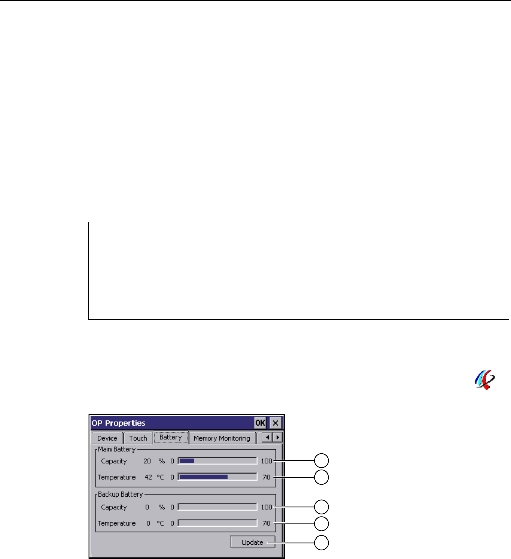
Requirements
You have opened the "OP Properties" dialog box, "Battery" tab, by touching the "OP"
icon.
① Charging status of main battery
② Temperature of main battery
③ Charging status of bridging battery
④ Temperature of bridging battery
⑤ Button to update the display
Configuring the operating system
6.15 Activate memory management
Mobile Panel 277F IWLAN
182 Operating Instructions, 12/2007, A5E01003940-01
Procedure
Proceed as follows:
1. Update the display if required by pressing the "Update" button.
2. Close the dialog.
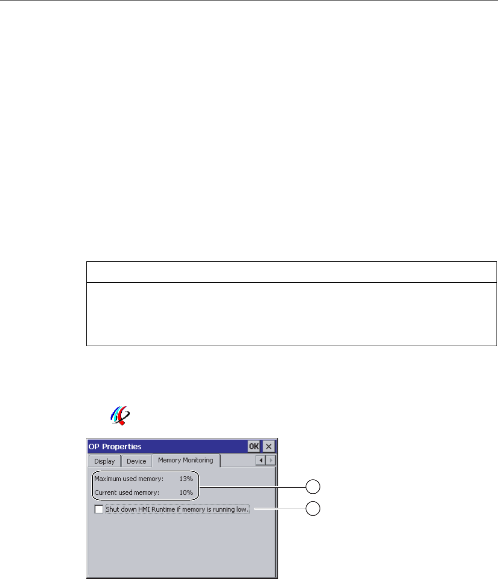
6.15 Activate memory management
Memory management
Provided the memory management is activated, the HMI device will automatically close the
project if the memory needs reorganizing during an active project.
The project is shut down and the HMI device will display a message. You have to restart the
project.
NOTICE
Memory management
If you do not activate memory management, undefined states can occur during the runtime
of the project.
Select memory management in the "OP Properties" dialog box.
Requirements
You have opened the "OP Properties" dialog box, "Memory Monitoring" tab, by touching the
"OP" icon.
① The maximum used memory since last power on of the HMI device and the current used
memory in percent.
② Check box for selecting memory management

Configuring the operating system
6.15 Activate memory management
Mobile Panel 277F IWLAN
Operating Instructions, 12/2007, A5E01003940-01 183
Procedure
Proceed as follows:
1. In order to start memory management, select the check box.
2. Confirm your entries.
The dialog closes.
Result
Memory management is activated.
Mobile Panel 277F IWLAN
Operating Instructions, 12/2007, A5E01003940-01 185
Commissioning the HMI device 7
7.1 Overview
Operating the HMI device
The HMI device is operated in the system as follows:
● As mobile device, with a battery
● As stationary device, in the charging station
For transfer and testing purposes, you can operate the HMI device in an office environment
as follows:
● As mobile device, with a battery
● As stationary device, with a tabletop power supply unit
● As stationary device, in the charging station
HMI device commissioning requirements
You must take the following steps before commissioning a project on the HMI device:
1. Install and connect up charging station
Alternatively, connect the HMI device to the tabletop power supply unit.
2. Charging the battery and inserting it in the HMI device
To charge the battery, you have the following possibilities:
– In the charging compartment of the charging station
– In the HMI device, in the charging station
– In the HMI device when connected to the tabletop power supply unit
3. Switch on the HMI device with the ON/OFF button
4. Commission and test WLAN
5. Define the settings for the transfer in the Control Panel.
6. Transfer project to the HMI device
Commissioning
Start the project once you have transferred it to the HMI device.

Commissioning the HMI device
7.2 Operating modes
Mobile Panel 277F IWLAN
186 Operating Instructions, 12/2007, A5E01003940-01
Note
If the project contains effective ranges, you must perform an acceptance test for the effective
ranges and transponders.
You can only start the project on the HMI device once the acceptance test is complete.
● If necessary: Testing zones
See also
Mounting the charging station (Page 66)
Connection of the charging station to the power supply (Page 70)
Programming the data channel (Page 160)
Acceptance of the system (Page 196)
7.2 Operating modes
Operating modes
The HMI device may be in the following operating modes:
● Offline
● Online
● Transfer
"Offline mode" and "Online mode" can be set on both the configuring PC and the HMI
device. To set these modes on the HMI device, use a corresponding operating element of
the project.
Changing the operating mode
The configuration engineer must have configured an appropriate operating element to allow
a change of the operating mode on the HMI device during ongoing operation.
Please refer to your system documentation to check whether additional information on this
subject is available there.
"Offline" operating mode
In this operating mode, the HMI device and the PLC do not communicate via the connections
configured in the WinCC flexible project. You can operate the current project on the HMI
device, but the project data will not be transferred.

Commissioning the HMI device
7.3 Using existing projects
Mobile Panel 277F IWLAN
Operating Instructions, 12/2007, A5E01003940-01 187
Note
Emergency stop button active
In "Offline" mode, the emergency stop button is active when the following requirements are
met:
• The HMI device is in an area with sufficient WLAN coverage.
• The HMI device is integrated in the safety program of the CPU.
"Online" operating mode
In this mode, the HMI device and PLC communicate. You can operate the plant on the HMI
device according to your system configuration.
"Transfer" mode
In this mode, you can transfer a project from the configuring PC to the HMI device or backup
and restore HMI device data, for example.
The following options are available for setting "Transfer" mode on the HMI device:
● When the HMI device starts up
Start "Transfer" mode manually in the HMI device Loader.
● During ongoing operation
Start the "Transfer" mode manually within the project using an operating element. With
automatic transfer, following a prompt the HMI device toggles to "Transfer" mode when a
transfer is initiated on the configuring PC.
7.3 Using existing projects
Note
Safety-related operator controls
The behavior and possible fields of application of the enabling button and emergency stop
button on the Mobile Panel 277F IWLAN are different from those of its predecessors, which
do not have Safety Integrated functions.
In this respect, you cannot reuse existing control programs.
For additional information on the safety-related operator controls, refer to the section titled
"Particular features of fail-safe operation" and the Function manual "Fail-safe operation of
the Mobile Panel 277F IWLAN".
You can reuse WinCC flexible projects for the following HMI devices:
● Mobile Panel 177 PN
● Mobile Panel 177 DP

Commissioning the HMI device
7.4 Data transmission options
Mobile Panel 277F IWLAN
188 Operating Instructions, 12/2007, A5E01003940-01
● Mobile Panel 277
Carry out an HMI device switch in WinCC flexible.
Adaptations
You must adapt the following aspects of the WinCC flexible project:
● Communication via WLAN
● Zone recognition and point recognition
– If you have used point detection with box ID in an existing project, you have the
following option:
Instead of using the connection box, use a zone consisting of at least one transponder
and set the previous box ID as the ID in this zone.
– If you are using zone recognition, you will need one or more transponders for one
zone.
In WinCC flexible, you can parameterize zones in "Device settings".
You can use zones to configure an easy way of selecting a zone-specific screen.
In this case you may also need to modify the control program from previous devices.
Additional information on this subject can be found in the WinCC flexible online help or in the
"WinCC flexible migration" user manual.
7.4 Data transmission options
Overview
The following table shows the options for data transfer between Mobile Panel 277 Wireless
and a configuring PC.
The Ethernet data channel is used for communication via WLAN and LAN (RJ45).
Type Data channel Mobile Panel 277 Wireless
USB Yes Backup
Ethernet Yes
USB Yes Restoring
Ethernet Yes
USB Yes Updating the operating system
Ethernet Yes
USB No Updating the operating system with
reset to factory settings Ethernet via the RJ 45
interface
Yes
USB Yes Transferring a project
Ethernet Yes
Installing or removing an option USB Yes

Commissioning the HMI device
7.5 Preparing and backing up a project
Mobile Panel 277F IWLAN
Operating Instructions, 12/2007, A5E01003940-01 189
Type Data channel Mobile Panel 277 Wireless
Ethernet Yes
USB Yes License key transferring or
transferring back Ethernet Yes
7.5 Preparing and backing up a project
7.5.1 Overview
Introduction
In order to operate the system with the HMI device, you must transfer the WinCC flexible
project to the HMI device.
Transferring the project to the HMI device
You can transfer a project to an HMI device as follows:
● Transfer from the configuring PC
● Restore from a PC using ProSave
In this case, an archived project is transferred from a PC to the HMI device.
WinCC flexible need not be installed on this PC.
Commissioning and recommissioning
● When the HMI device is commissioned there is no project at first.
The HMI device is also in this state after the operating system has been updated.
● When recommissioning, any project already on the HMI device is replaced.
See also
Operating modes (Page 186)

Commissioning the HMI device
7.5 Preparing and backing up a project
Mobile Panel 277F IWLAN
190 Operating Instructions, 12/2007, A5E01003940-01
7.5.2 Transfer
7.5.2.1 Overview
Transfer
At the end of the configuration phase, transfer the executable project from the configuring
PC to the HMI device.
You can start the "Transfer" mode manually or automatically on the HMI device.
Transferred data is written directly to the internal flash memory on the HMI device. For the
transfer, you use a data channel which you have to configure before starting a transfer.
Backtransfer
You have the option to transfer the compressed project file together with the runtime project
to the HMI device. If necessary, the compressed project file can be transferred back to the
configuring PC and edited.
The HMI device must be equipped with an external memory to which the compressed project
file can be saved.
NOTICE
No checking of the project files
WinCC flexible does not check whether the compressed project file stored on the HMI
device corresponds to the existing runtime project.
7.5.2.2 Starting manual transfer
Introduction
You can manually switch the HMI device to "Transfer" mode as follows:
● With a configured operating element during ongoing operation
● In the Loader of the HMI device
Requirements
● The project "*.hmi" that you want to transfer is open in WinCC flexible on the configuring
PC
● The HMI device is connected to this configuring PC
● The data channel is programmed on the HMI device
● The HMI device is in "Transfer" mode

Commissioning the HMI device
7.5 Preparing and backing up a project
Mobile Panel 277F IWLAN
Operating Instructions, 12/2007, A5E01003940-01 191
Procedure
Proceed as follows:
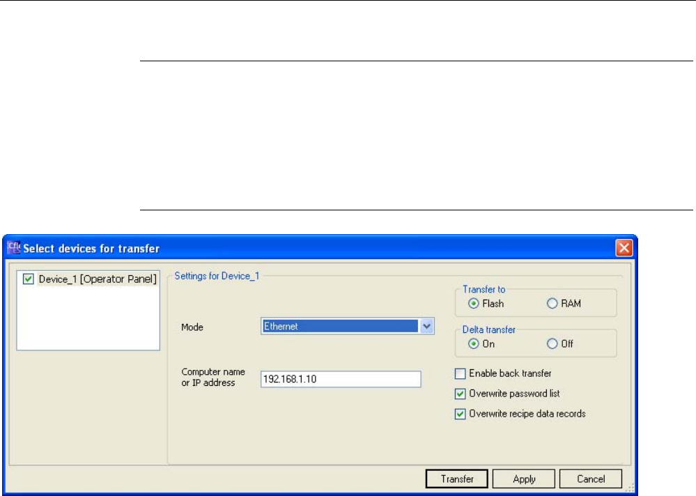
1. On the configuring PC, select the "Transfer settings" command in the menu "Project >
Transfer" in WinCC flexible.
The "Select devices for transfer" dialog opens.
2. Select the HMI device in the left area of the dialog.
3. Select the type of connection between the HMI device and the configuring PC.
4. Set the connection parameters.
5. Set the transfer parameters in the right area of the dialog.
6. If you wish to transfer the compressed project file together with the executable project to
the HMI device:
Select the "Enable backtransfer" check box.
7. Start transfer in WinCC flexible with "Transfer".
The configuring PC checks the connection to the HMI device. The project is transferred to
the HMI device. If the connection is not available or is defective, an error message is
displayed on the configuring PC.
Result
When the transfer is completed successfully, the project can be found on the HMI device.
The transferred project is then started automatically.
See also
Operating modes (Page 186)
Data transmission options (Page 188)
Programming the data channel (Page 160)
7.5.2.3 Starting automatic transfer
Introduction
If automatic transfer is selected, the HMI device automatically switches to "Transfer" mode
during operation as soon as a transfer is initiated on the connected configuring PC.
Note
The HMI device only switches to "Transfer" mode in the current project.
Automatic transfer is particularly suited for the test phase of a new project since transfer is
completed without interfering with the HMI device.

Commissioning the HMI device
7.5 Preparing and backing up a project
Mobile Panel 277F IWLAN
192 Operating Instructions, 12/2007, A5E01003940-01
NOTICE
Undesired system responses
If automatic transfer has been selected on the HMI device and a transfer is then initiated on
the configuring PC, the current project is automatically terminated following a prompt.
The HMI device then automatically switches to "Transfer" mode. The transfer mode can
trigger undesired responses in the system.
After the commissioning phase, deactivate the automatic transfer so that the HMI device
cannot be inadvertently switched to transfer mode.
You can issue a password in the Control Panel to restrict access to the transfer settings
and thus avoid unauthorized modifications.
Requirements
● The project "*.hmi" that you want to transfer is open in WinCC flexible on the configuring
PC
● The HMI device is connected to this configuring PC
● The data channel is programmed on the HMI device
● The automatic transfer is activated in the data channel for the transfer
● The project is started on the HMI device
Procedure
Proceed as follows:
1. On the configuring PC, select the "Transfer settings" command in the menu "Project >
Transfer" in WinCC flexible.
The "Select devices for transfer" dialog opens.
2. Select the HMI device in the left area of the dialog.
3. Select the type of connection between the HMI device and the configuring PC.
4. Set the connection parameters.
5. Set the transfer parameters in the right area of the dialog.
6. If you wish to transfer the compressed project file together with the executable project to
the HMI device:
Select the "Enable backtransfer" check box.
7. Start transfer in WinCC flexible with "Transfer".
The configuring PC checks the connection to the HMI device.
If the HMI device is integrated, it displays the "Start removal" dialog box.
8. Press one of the enabling buttons to confirm the dialog box.
The HMI device is removed. The current project is terminated. The HMI device then
automatically switches to transfer mode. The project is transferred to the HMI device. If

Commissioning the HMI device
7.5 Preparing and backing up a project
Mobile Panel 277F IWLAN
Operating Instructions, 12/2007, A5E01003940-01 193
the connection is not available or is defective, an error message is displayed on the
configuring PC.
Result
When the transfer is completed successfully, the project can be found on the HMI device.
The transferred project is then started automatically.
See also
Operating modes (Page 186)
Data transmission options (Page 188)
Programming the data channel (Page 160)
7.5.2.4 Starting backtransfer
Requirements
● No project is open on the configuring PC in WinCC flexible
● The HMI device is connected to this configuring PC
● The data channel is programmed on the HMI device
● The HMI device is in "Transfer" mode
● The memory card containing the compressed project file is inserted into the HMI device
Procedure
Proceed as follows:
1. On the configuring PC, select the "Communication settings" command in the menu
"Project > Transfer" in WinCC flexible.
The "Communication settings" dialog box opens.
2. Select the type of HMI device.
3. Select the type of connection between the HMI device and the configuring PC.
4. Set the connection parameters.
5. Close the dialog with "OK".
6. Select the "Transfer" > "Backtransfer" command in the "Project" menu.
The "Backtransfer" dialog opens.
7. Click "OK" to start the backtransfer process.
The configuring PC checks the connection to the HMI device. The compressed project file
is transferred back from the HMI device to the configuring PC. If the connection is not
available or is defective, an error message is displayed on the configuring PC.

Commissioning the HMI device
7.5 Preparing and backing up a project
Mobile Panel 277F IWLAN
194 Operating Instructions, 12/2007, A5E01003940-01
Result
After successful backtransfer, the project is opened on the configuring PC in WinCC flexible.
See also
Operating modes (Page 186)
Data transmission options (Page 188)
Programming the data channel (Page 160)
7.5.3 Testing a project
Introduction
There are two options to test a project:
● Test the project on the configuring PC
You can test a project at a configuring PC, using a simulator. For detailed information,
refer to the "WinCC flexible" user manual and to the WinCC flexible online help.
● Offline testing of the project on the HMI device
Offline testing means that communication between the HMI device and PLC connections,
which have been configured in WinCC flexible, is down while the test is being carried out.
The PROFIsafe connection between the HMI device and PLC is also available in "Offline"
mode.
● Online testing of the project on the HMI device
Online testing means that the HMI device and PLC communicate with each other during
testing.
Perform the tests, starting with the "Offline test", followed by the "Online test".
Note
You should always test the project on the HMI device on which the project will be used.
Check the following:
1. WLAN coverage
2. Zone recognition, if zones have been configured
3. Check the correct layout of the screens
4. Check the screen navigation
5. Check the input objects
6. Enter the tag values
The test increases the certainty that the project will run error-free on the HMI device.

Commissioning the HMI device
7.5 Preparing and backing up a project
Mobile Panel 277F IWLAN
Operating Instructions, 12/2007, A5E01003940-01 195
Note
Test without effective ranges
Perform the test without effective ranges.
A system acceptance test must be performed as soon as you have configured effective
ranges in your project. The effective ranges and assigned transponders will be tested as part
of the acceptance test.
Test the effective ranges separately.
Requirements for offline testing
● The project has been transferred to the HMI device
● The HMI device is in "Offline" mode.
Procedure
In "Offline" mode, you can test individual project functions on the HMI device without them
being affected by the PLC. PLC tags, therefore, are not updated.
Test the operating elements and visualization of the project as far as possible without
connecting to the PLC.
Requirements for online testing
● The project has been transferred to the HMI device
● The HMI device is in "Online" mode
Procedure
In "Online" mode, you can test individual project functions on the HMI device without them
being affected by the PLC. PLC tags are updated in this case.
You have the option to test all communication-dependent functions, for example alarms, etc.
Test the operating elements and views of the project.
See also
Acceptance of the system (Page 196)
Testing zones (Page 200)

Commissioning the HMI device
7.5 Preparing and backing up a project
Mobile Panel 277F IWLAN
196 Operating Instructions, 12/2007, A5E01003940-01
7.5.4 Acceptance of the system
7.5.4.1 Overview
Introduction
The acceptance of the system includes the following areas:
● Configuring the F CPU and fail-safe I/O
● Safety program
● Effective ranges and transponders
Acceptance steps that you must execute in order to operate the Mobile Panel 277F IWLAN
HMI device in a system with effective ranges are described in detail in these operating
instructions.
The following manuals contain more detailed notes on acceptance of the system:
● Function manual "Fail-safe operation of the Mobile Panel 277F IWLAN"
● Manual "S7 distributed safety, configuring and programming", Chapter "System
acceptance test".
Acceptance of the effective ranges and transponders
For acceptance of the effective ranges and transponders you must determine a CRC
checksum in the plant and enter it in the project. After subsequent project transfer to the HMI
device you can operate the plant with the HMI device.
Note
If you change transponders in the plant you must execute another acceptance of the plant.
When executing an acceptance test of the system, all of the relevant application-specific
standards must be observed.
7.5.4.2 Accepting effective ranges and transponders
Introduction
For safe operation, the project of the HMI device must precisely match the plant.
For this reason when first starting a project in the plant, you must verify all effective ranges
with all transponders. The result of the verification is a CRC checksum that you must enter in
the project. Then you must transfer the project to the HMI device again.
Note
Transponders that are exclusively assigned to one zone are not considered in this
verification.

Commissioning the HMI device
7.5 Preparing and backing up a project
Mobile Panel 277F IWLAN
Operating Instructions, 12/2007, A5E01003940-01 197
Acceptance if there are changes
If you change the configuration of transponders and effective ranges in the system, then you
must adjust the configuration. Then you must accept the effective ranges and transponders
again.
Requirements
● In the project:
– Effective ranges and transponders must be configured in the project.
– The project has been transferred to the HMI device.
● In the plant:
– The transponders must be mounted in the plant in such a manner that the effective
ranges stored in the project are formed.
– Batteries must be inserted in the transponders. The ID must be set on the
transponders that is stored in the project for these transponders.
– The IDs of the effective ranges must be marked in the plant.
– The quality of the WLAN range must be sufficient.
Procedure
Proceed as follows:
1. Switch on the HMI device.
The Windows CE desktop with Loader is displayed.
2. If the project does not start automatically, start the project.
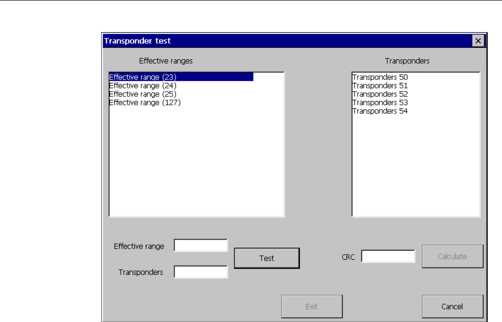
The "Transponder test" dialog box opens.
Commissioning the HMI device
7.5 Preparing and backing up a project
Mobile Panel 277F IWLAN
198 Operating Instructions, 12/2007, A5E01003940-01
To the left you will see the list with the names of all configured effective ranges.
3. In the "Effective ranges" list highlight the first effective range that you want to verify.
In the "Transponder" list on the right, the names of the transponders are displayed that
are assigned to the effective range in the project.
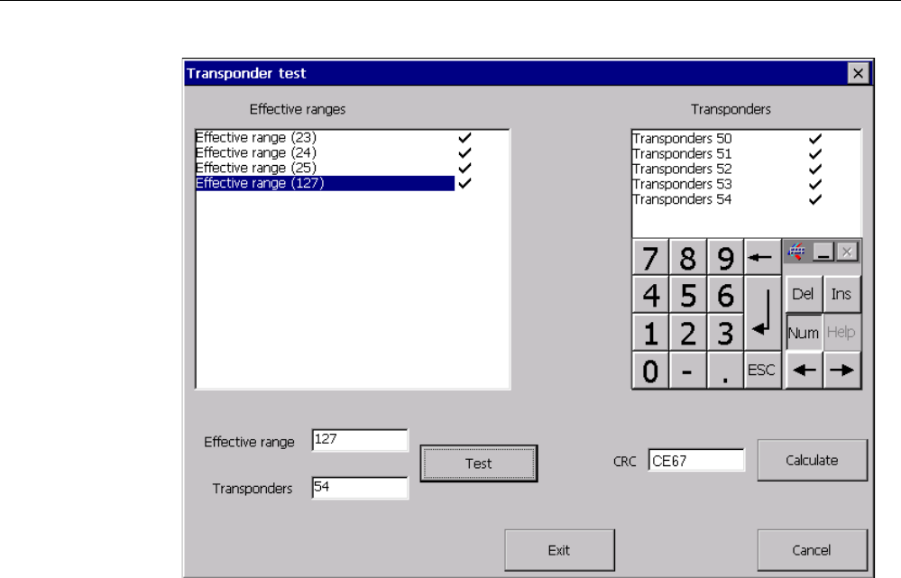
4. Go to the first transponder that you want to verify in the "Transponder" list.
5. In the system, read the ID of the highlighted effective range and enter this ID in the
"Effective range" box.
6. Enter the ID of the transponder where you are located in the "Transponder" box.
7. Verify the entered ID with the "Test" button.
When the HMI device receives the signal of the transponder specified, that transponder is
considered to be checked. The transponder will be marked with a check mark in the list.
8. Repeat steps 4 to 7 for all transponders of this effective range.
If you have successfully checked all transponders of an effective range, that effective
range will be indicated with a check mark in the list.
9. Select the next effective range in the list.
10. Repeat steps 4 to 7 for all transponders assigned to this effective range.
11. Verify all additional effective ranges in the list to the left.
12. When you have successfully verified all effective ranges, touch the "Calculate" button.
The HMI device calculates the CRC checksum. The CRC checksum is displayed in the
"CRC" box.
Commissioning the HMI device
7.5 Preparing and backing up a project
Mobile Panel 277F IWLAN
Operating Instructions, 12/2007, A5E01003940-01 199
13. Open the project in WinCC flexible ES.
14. Enter the checksum in the "Effective ranges" editor.
15. Transfer the project to the HMI device again.
Result
The HMI device can now be used for operating and monitoring the system.
7.5.4.3 Testing effective ranges
After successful verification of the transponders and effective ranges you must test in the
plant whether the expansion of the configured effective ranges corresponds to the planning.
If the operating elements "Effective range name" and "Effective range quality" are available
in the project, you can check the effective ranges on the HMI device.
In particular, check the following cases:
● Do the limits of the effective range run as planned?
Note particularly that machine operations from excessive distances are not permitted.
● Does the indicator that belongs to the effective range show whether an HMI device is
logged on at the effective range?
● Are moving machine parts influencing the reception of the transponders? Check also the
extreme positions of moving machine parts.
● Is WLAN coverage ensured everywhere in the effective range?

Commissioning the HMI device
7.5 Preparing and backing up a project
Mobile Panel 277F IWLAN
200 Operating Instructions, 12/2007, A5E01003940-01
7.5.5 Testing zones
If zones are present in the system, you need to test whether the HMI device is detecting
them.
Note
The following requirements must be fulfilled in order to test zones:
• The project has been transferred to the HMI device and started
• The HMI device is in online mode
• The transponders have been fitted and the transponder IDs are set
If the operating elements "Zone label" and "Zone quality" are present in the project, you can
check the zones on the HMI device.
In particular, check the following cases:
● Are the zone limits operating as planned?
Are moving machine parts influencing the reception of the transponders? Check also the
extreme positions of moving machine parts.
● Is WLAN coverage ensured in all parts of the zone?
7.5.6 Backup and restore
7.5.6.1 Overview
Backup and restore
You can back up and restore the following data found in the internal flash memory of the HMI
device with a PC:
● Project and HMI device image
● Password list
● Recipe data
● License keys
Use one of the following tools for backup and restore:
● WinCC flexible
● ProSave
Note
Alternatively, use the Control Panel to back up to an external memory device.

Commissioning the HMI device
7.5 Preparing and backing up a project
Mobile Panel 277F IWLAN
Operating Instructions, 12/2007, A5E01003940-01 201
General information
NOTICE
Resetting to factory defaults required
If a complete restore operation is interrupted due to power failure on the HMI device, the
operating system of the HMI device may be deleted! In this case, you have to reset the HMI
device to its factory settings.
Compatibility conflict
If a message is output on the HMI device warning of a compatibility conflict during the
restore operation, the operating system must be updated.
7.5.6.2 Backup and restore using WinCC flexible
Requirements
● No project is open on the configuring PC in WinCC flexible
● The HMI device is connected to this configuring PC
● The data channel is programmed on the HMI device
Procedure for backup
Proceed as follows:
1. On the configuring PC, select the "Communication settings" command in the menu
"Project > Transfer" in WinCC flexible.
The "Communication settings" dialog box opens.
2. Select the type of HMI device.
3. Select the type of connection between the HMI device and the configuring PC.
4. Set the connection parameters.
5. Close the dialog with "OK".
6. Select the "Backup" command in the menu "Project > Transfer" in WinCC flexible.
The "Backup settings" dialog opens.
7. Select the data to be backed up.
8. Select a destination folder and a file name for the "*.psb" backup file.
9. Set "Transfer" mode on the HMI device.
10. Start the backup operation in WinCC flexible with "OK" on the configuring PC.
If automatic transfer has been selected on the HMI device, following a prompt the HMI
device automatically switches to "Transfer" mode when a backup is initiated.
11. Follow the instructions in WinCC flexible.

Commissioning the HMI device
7.5 Preparing and backing up a project
Mobile Panel 277F IWLAN
202 Operating Instructions, 12/2007, A5E01003940-01
A status view opens to indicate the progress of the operation.
Result
The system outputs a message when the backup is completed.
The relevant data is now backed up on the configuring PC.
Procedure for restoring
Proceed as follows:
1. On the configuring PC, select the "Communication settings" command in the menu
"Project > Transfer" in WinCC flexible.
The "Communication settings" dialog box opens.
2. Select the type of HMI device.
3. Select the type of connection between the HMI device and the configuring PC.
Set the connection parameters.
4. Close the dialog with "OK".
5. Select the "Restore" command in the menu "Project > Transfer" in WinCC flexible.
The "Restore settings" dialog opens.
6. Select the "*.psb" backup file to be restored from the "Open" field.
You can see the HMI device for which the backup file was created and the type of backup
data the file contains.
7. Set "Transfer" mode on the HMI device.
If automatic transfer has been selected on the HMI device, following a prompt the HMI
device automatically switches to "Transfer" mode when a restore operation is initiated.
8. Start the restore operation in WinCC flexible with "OK" on the configuring PC.
If there are license keys both on the HMI device and in the backup, a dialog box will
appear. Use this dialog to establish whether you want to overwrite the license keys or
abort the restore process.
– If necessary, abort the backup and first back up the HMI device's license keys.
– Then restart the restore process.
Follow the instructions in WinCC flexible.
A status view opens to indicate the progress of the operation.
Result
When the restore is successfully completed, the data backed up on the configuring PC is
now on the HMI device.
See also
Operating modes (Page 186)

Commissioning the HMI device
7.5 Preparing and backing up a project
Mobile Panel 277F IWLAN
Operating Instructions, 12/2007, A5E01003940-01 203
Data transmission options (Page 188)
Programming the data channel (Page 160)
Overview (Page 200)
7.5.6.3 Backup and restore using ProSave
Requirements
● The HMI device is connected to a PC on which ProSave is installed
● The data channel is programmed on the HMI device
Procedure for backup
Proceed as follows:
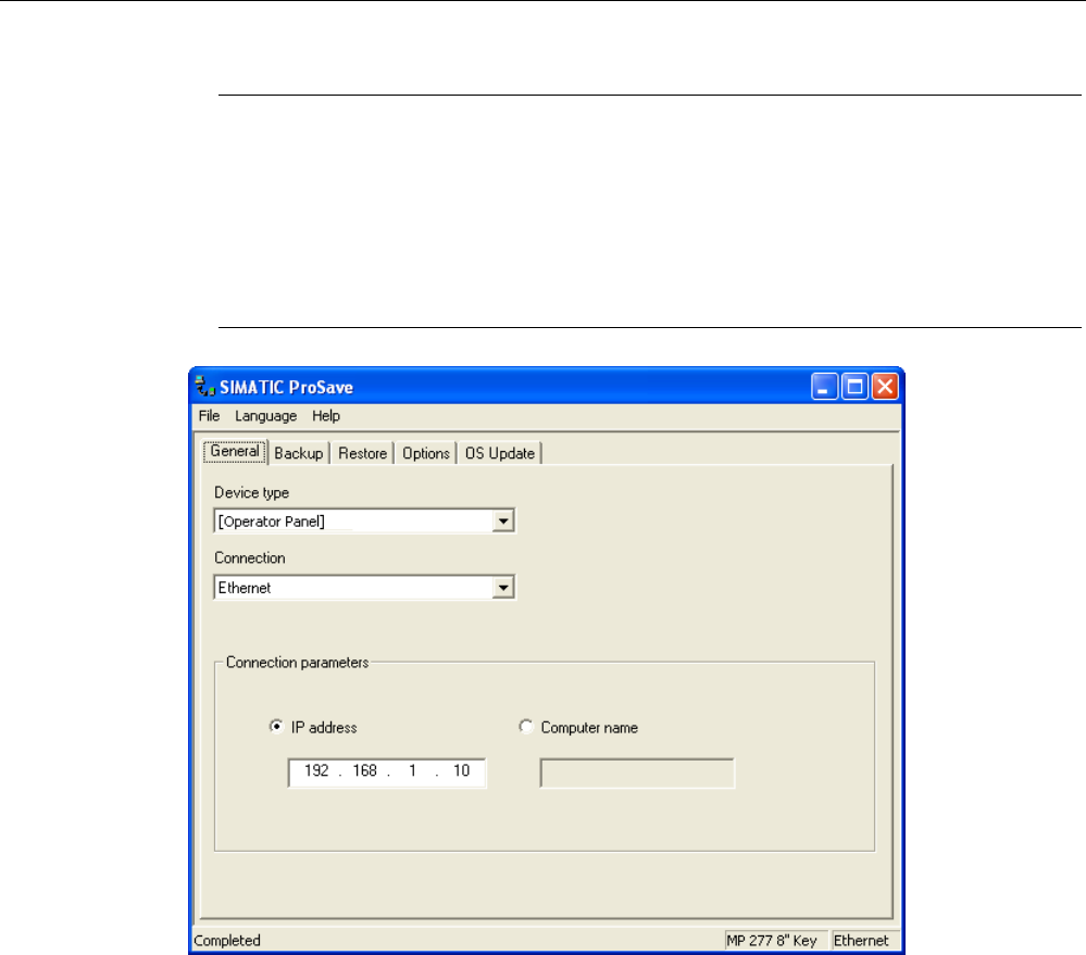
1. From the Windows Start menu, start ProSave on the PC.
2. Select the HMI device type in the "General" tab.
3. Select the type of connection between the HMI device and the PC.
4. Set the connection parameters.
5. Select the data to be backed up in the "Backup" tab.
6. Select a destination folder and a file name for the "*.psb" backup file.
7. Set "Transfer" mode on the HMI device.
If automatic transfer has been selected on the HMI device, following a prompt the HMI
device automatically switches to "Transfer" mode when a backup is initiated.
8. Start the backup operation in ProSave with "Start Backup".
9. Follow the instructions in ProSave.
A status view opens to indicate the progress of the operation.
Result
The system outputs a message when the backup is completed.
The relevant data is now backed up on the PC.
Procedure for restoring
Proceed as follows:
1. From the Windows Start menu, start ProSave on the PC.
2. Select the HMI device type in the "General" tab.
3. Select the type of connection between the HMI device and the PC.
4. Set the connection parameters.
5. Select the "*.psb" backup file to be restored from the "Restore" tab.

Commissioning the HMI device
7.5 Preparing and backing up a project
Mobile Panel 277F IWLAN
204 Operating Instructions, 12/2007, A5E01003940-01
You can see the HMI device for which the backup file was created and the type of backup
data the file contains.
6. Set "Transfer" mode on the HMI device.
If automatic transfer has been selected on the HMI device, following a prompt the HMI
device automatically switches to "Transfer" mode when a restore operation is initiated.
7. Start the restore operation in ProSave on the PC with "Start Restore".
If there are license keys both on the HMI device and in the backup, a dialog box will
appear. Use this dialog to establish whether you want to overwrite the license keys or
abort the restore process.
– If necessary, abort the restore and first back up the HMI device's license keys.
– Then restart the restore process.
8. Follow the instructions in ProSave.
A status view opens to indicate the progress of the operation.
Result
When the restore is successfully completed, the data backed up on the PC is now on the
HMI device.
See also
Operating modes (Page 186)
Data transmission options (Page 188)
Programming the data channel (Page 160)
Overview (Page 200)
7.5.7 Updating the operating system
7.5.7.1 Overview
Updating the operating system
A compatibility conflict may occur when transferring a project to the HMI device. This is
caused by different versions of the configuration software used and the HMI device image
available on the HMI device. If there are different versions, the transfer is aborted. A
message indicating a compatibility conflict is displayed on the configuring PC.
There are two ways to match the versions:
● Update the HMI device image if the project was created with the most recent version of
the configuration software
● Transfer a matching version of the HMI device image if you do not want to adapt the
project for the HMI device to the most recent version of the configuration software for the
project

Commissioning the HMI device
7.5 Preparing and backing up a project
Mobile Panel 277F IWLAN
Operating Instructions, 12/2007, A5E01003940-01 205
General information
NOTICE
Resetting to factory defaults required
If the update of the HMI device image is interrupted due to a power failure on the HMI
device, the operating system of the HMI device may be deleted. In this case, you have to
reset the HMI device to its factory settings.
NOTICE
Data loss
All data on the HMI device, such as the project and passwords, will be deleted when you
update the operating system.
Note
Calibrating the touch screen
After updating the operating system, you may have to recalibrate the touch screen.
Resetting to factory settings
In ProSave or WinCC flexible, you can update the operating system with or without resetting
to factory settings.
CAUTION
IP65 degree of protection not fulfilled
To update the operating system and reset to factory settings, you need an Ethernet
connection over the RJ45 interface.
If you connect the configuring PC directly to the HMI device through the RJ45 interface, you
must open the connection compartment. If the connection bay is open, degree of protection
IP 65 is not fulfilled.
● Updating the operating system without resetting to factory settings
First, switch into "Transfer" mode on the HMI device or use the automatic transfer
function if the project is active. Then start the operating system update in ProSave or
WinCC flexible.
● Updating the operating system with reset to factory setting
NOTICE
Loss of license keys
The license keys on the HMI device will be deleted when resetting to factory settings.
The license keys on the HMI device will be retained when updating the operating system
without resetting to factory settings.

Commissioning the HMI device
7.5 Preparing and backing up a project
Mobile Panel 277F IWLAN
206 Operating Instructions, 12/2007, A5E01003940-01
NOTICE
Data channels
When resetting to factory settings, all data channel parameters are reset. The transfer
can only be started following reconfiguration of the data channels.
Note
You have to perform an operating system update with reset to factory settings if the HMI
device does not yet have an operating system or if the operating system of the HMI
device is corrupt.
First, start the operating system update in ProSave or WinCC flexible and switch the
power on the HMI device off and on again when prompted.
7.5.7.2 Updating the operating system using WinCC flexible
Requirements
● No project is open on the configuring PC in WinCC flexible
● The HMI device is connected to this configuring PC
● The data channel is programmed on the HMI device
Procedure
Proceed as follows:
1. On the configuring PC, select the "Communication settings" command in the menu
"Project > Transfer" in WinCC flexible.
The "Communication settings" dialog box opens.
2. Select the type of HMI device.
3. Select the type of connection between the HMI device and the configuring PC.
4. Set the connection parameters.
5. Close the dialog with "OK".
6. In WinCC flexible, select the command "Update OS" in the "Project > Transfer" menu.
7. In "Image path", select the HMI device image file "*.img".
The HMI device image files are available under "WinCC flexible Images" in the
WinCC flexible installation folder or on the WinCC flexible installation CD.
In the output area, you are provided information on the version of the HMI device image
file after it is opened.
8. Set "Transfer" mode on the HMI device.
If automatic transfer has been activated on the HMI device, following a prompt the HMI
device automatically switches to "Transfer" mode when an update is initiated.
9. In WinCC flexible, select "Update OS" on the configuring PC to run the operating system
update.

Commissioning the HMI device
7.5 Preparing and backing up a project
Mobile Panel 277F IWLAN
Operating Instructions, 12/2007, A5E01003940-01 207
10. Follow the instructions in WinCC flexible.
During the operating system update a status view opens to indicate progress.
Result
A message is displayed when the operating system update is successfully completed.
This operation has deleted the project data from the HMI device.
See also
Operating modes (Page 186)
Data transmission options (Page 188)
Programming the data channel (Page 160)
Overview (Page 204)
7.5.7.3 Updating the operating system using ProSave
Requirements
● The HMI device is connected to a PC on which ProSave is installed
● The data channel is programmed on the HMI device
Procedure
Proceed as follows:
1. From the Windows Start menu, start ProSave on the PC.
2. Select the HMI device type in the "General" tab.
3. Select the type of connection between the HMI device and the PC.
4. Set the connection parameters.
5. Select the "OS Update" tab.
6. In "Image path", select the HMI device image file "*.img".
The HMI device image files are available under "WinCC flexible Images" in the
WinCC flexible installation folder or on the WinCC flexible installation CD.
In the output area, you are provided information on the version of the HMI device image
file after it is opened.
7. Set "Transfer" mode on the HMI device.
If automatic transfer has been activated on the HMI device, following a prompt the HMI
device automatically switches to "Transfer" mode when an update is initiated.
8. Select "Update OS" on the PC to run the operating system update.
9. Follow the instructions in ProSave.
During the operating system update a status view opens to indicate progress.

Commissioning the HMI device
7.5 Preparing and backing up a project
Mobile Panel 277F IWLAN
208 Operating Instructions, 12/2007, A5E01003940-01
Result
A message is displayed when the operating system update is successfully completed.
This operation has deleted the project data from the HMI device.
See also
Operating modes (Page 186)
Data transmission options (Page 188)
Programming the data channel (Page 160)
Overview (Page 204)
7.5.7.4 Resetting to factory settings with WinCC flexible
Requirements
● No project is open on the configuring PC in WinCC flexible
● The HMI device is connected to this configuring PC over the Ethernet
● Have the MAC address of your HMI device's Ethernet interface to hand.
– The MAC address is displayed briefly when the HMI device is turned on.
– The MAC address is displayed in the "PROFINET" dialog in the Control Panel.
Procedure for setting the PC interface
1. Select "Start > Control Panel > Set PG/PC interface".
2. Select "S7ONLINE (STEP7) -> TCP/IP" from the "Application access point" area.
3. Select the interface which is connected to the HMI device from the "Interface
parameterization used" area.
4. Confirm your entries.
Procedure for resetting to factory settings
Proceed as follows:
1. Turn off the power supply to the HMI device.
2. On the configuring PC, select the "Communication settings" command in the menu
"Project > Transfer" in WinCC flexible.
The "Communication settings" dialog box opens.
3. Select the HMI device type from the "General" tab, and select "Ethernet" from the
"Connection" area.
4. Enter an IP address.
Commissioning the HMI device
7.5 Preparing and backing up a project
Mobile Panel 277F IWLAN
Operating Instructions, 12/2007, A5E01003940-01 209
Note
Possible address conflicts with incorrect IP address
Do not use a dynamic IP configuration for "Reset factory settings".
Define an IP address which the HMI device is going to receive from the configuration
station during the update process.
If the HMI device has already been used with WinCC flexible or ProSave you can use the
existing IP address for "Reset factory settings".
1. Confirm your entries.
2. In WinCC flexible, select the command "Update OS" in the "Project > Transfer" menu.
3. Select the "Reset factory settings" check box.
A text box opens where you can enter the MAC address.
4. Enter the HMI device's MAC address in the text box.
5. In "Image path", select the HMI device image file "*.img".
The HMI device image files are available under "WinCC flexible Images" in the
WinCC flexible installation folder or on the WinCC flexible installation CD.
In the output area, you are provided information on the version of the HMI device image
file after it is opened.
6. In WinCC flexible, select "Update OS" on the configuring PC to run the operating system
update.
7. Follow the instructions in WinCC flexible.
During the operating system update a status view opens to indicate progress.
Result
A message is displayed when the operating system update is successfully completed.

Commissioning the HMI device
7.5 Preparing and backing up a project
Mobile Panel 277F IWLAN
210 Operating Instructions, 12/2007, A5E01003940-01
This operation has deleted the project data from the HMI device. The factory settings are
reset.
Note
Calibrating the touch screen
After the restore, you may have to re-calibrate the touch screen.
See also
Operating modes (Page 186)
Data transmission options (Page 188)
Programming the data channel (Page 160)
Overview (Page 204)
7.5.7.5 Resetting to factory settings with ProSave
Requirements
● The HMI device is connected over the Ethernet to a PC on which ProSave is installed
● When updating the operating system with reset to factory setting only:
Have the MAC address of your HMI device's Ethernet interface to hand.
– The MAC address is displayed briefly when the HMI device is turned on.
– The MAC address is displayed in the "PROFINET" dialog in the Control Panel.
Procedure for setting the PC interface
1. Select "Start > Control Panel > Set PG/PC interface".
2. Select "S7ONLINE (STEP7) -> TCP/IP" from the "Application access point" area.
3. Select the interface which is connected to the HMI device from the "Interface
parameterization used" area.
4. Confirm your entries.
Procedure for resetting factory settings
Proceed as follows:
1. Turn off the power supply to the HMI device.
2. From the Windows Start menu, start ProSave on the PC.
3. Select the HMI device type from the "General" tab, and select "Ethernet" from the
"Connection" area.
4. Enter an IP address.
Commissioning the HMI device
7.5 Preparing and backing up a project
Mobile Panel 277F IWLAN
Operating Instructions, 12/2007, A5E01003940-01 211
Note
Possible address conflicts with incorrect IP address
Do not use a dynamic IP configuration for "Reset factory settings".
Define an IP address which the HMI device is going to receive from the configuration
station during the update process.
If the HMI device has already been used with WinCC flexible or ProSave you can use the
existing IP address for "Reset factory settings".
1. Change to the "OS Update" tab.
2. Select the "Reset factory settings" check box.
A text box opens where you can enter the MAC address.
3. Enter the MAC address of the HMI device
4. In "Image path", select the HMI device image file "*.img".
The HMI device image files are available under "WinCC flexible Images" in the
WinCC flexible installation folder or on the WinCC flexible installation CD.
In the output area, you are provided information on the version of the HMI device image
file after it is opened.
5. Select "Update OS" on the PC to run the operating system update.
6. Follow the instructions in ProSave.
During the operating system update a status view opens to indicate progress.

Commissioning the HMI device
7.5 Preparing and backing up a project
Mobile Panel 277F IWLAN
212 Operating Instructions, 12/2007, A5E01003940-01
Result
A message is displayed when the operating system update is successfully completed.
This operation has deleted the project data from the HMI device. The factory settings are
reset.
Note
Calibrating the touch screen
After the restore, you may have to re-calibrate the touch screen.
See also
Operating modes (Page 186)
Data transmission options (Page 188)
Programming the data channel (Page 160)
Overview (Page 204)
7.5.8 Installing and removing options
7.5.8.1 Overview
Installing and removing options
You can install options on the HMI device, for example, additional programs developed
especially for the HMI device.
You can also remove the option from the HMI device again.
Note
License key
A license key may be needed to run an option. The license key unlocks the option for use.
7.5.8.2 Installing and removing options using WinCC flexible
Requirements
● No project is open on the configuring PC in WinCC flexible
● The HMI device is connected to this configuring PC
● The data channel is programmed on the HMI device

Commissioning the HMI device
7.5 Preparing and backing up a project
Mobile Panel 277F IWLAN
Operating Instructions, 12/2007, A5E01003940-01 213
Procedure for installing an option
Proceed as follows:
1. On the configuring PC, select the "Communication settings" command in the menu
"Project > Transfer" in WinCC flexible.
The "Communication settings" dialog box opens.
2. Select the type of HMI device.
3. Select the type of connection between the HMI device and the configuring PC.
4. Set the connection parameters.
5. Close the dialog with "OK".
6. Select the "Options" command in the menu "Project > Transfer" in WinCC flexible.
7. Select the desired option under "Available options".
8. Set "Transfer" mode on the HMI device.
If automatic transfer is activated on the HMI device, following a prompt the HMI device
automatically switches to "Transfer" mode when the installation of an option is initiated.
9. Start the installation of the option in WinCC flexible on the configuring PC with the ">>"
button.
10. Follow the instructions in WinCC flexible.
A status display appears indicating the progress of the installation.
Result
The option has now been installed on the HMI device.
Procedure for removing an option
Proceed as follows:
1. On the configuring PC, select the "Communication settings" command in the menu
"Project > Transfer" in WinCC flexible.
The "Communication settings" dialog box opens.
2. Select the type of HMI device.
3. Select the type of connection between the HMI device and the configuring PC.
4. Set the connection parameters.
5. Close the dialog with "OK".
6. Select the "Options" command in the menu "Project > Transfer" in WinCC flexible.
7. Press the "Device status" button to update the display.
8. Select the desired option under "Installed options".
9. Set "Transfer" mode on the HMI device.
If automatic transfer is activated on the HMI device, following a prompt the HMI device
automatically switches to "Transfer" mode when the removal of an option is initiated.

Commissioning the HMI device
7.5 Preparing and backing up a project
Mobile Panel 277F IWLAN
214 Operating Instructions, 12/2007, A5E01003940-01
10. Start the removal of the option in WinCC flexible on the configuring PC with the "<<"
button.
11. Follow the instructions in WinCC flexible.
A status display appears indicating the progress of the removal.
Result
The option has now been removed on the HMI device.
See also
Operating modes (Page 186)
Data transmission options (Page 188)
Programming the data channel (Page 160)
Overview (Page 212)
7.5.8.3 Installing and removing options using ProSave
Requirements
● The HMI device is connected to a PC on which ProSave is installed
● The data channel is programmed on the HMI device
Procedure for installing an option
Proceed as follows:
1. From the Windows Start menu, start ProSave on the PC.
2. Select the HMI device type in the "General" tab.
3. Select the type of connection between the HMI device and the PC.
4. Set the connection parameters.
5. Select the "Options" tab.
6. Select the desired option under "Available options".
7. Set "Transfer" mode on the HMI device.
If automatic transfer is activated on the HMI device, following a prompt the HMI device
automatically switches to "Transfer" mode when the installation of an option is initiated.
8. Start the installation of the option in ProSave with the ">>" button.
9. Follow the instructions in ProSave.
A status display appears indicating the progress of the installation.

Commissioning the HMI device
7.5 Preparing and backing up a project
Mobile Panel 277F IWLAN
Operating Instructions, 12/2007, A5E01003940-01 215
Result
The option has now been installed on the HMI device.
Procedure for removing an option
Proceed as follows:
1. From the Windows Start menu, start ProSave on the PC.
2. Select the HMI device type in the "General" tab.
3. Select the type of connection between the HMI device and the PC.
4. Set the connection parameters.
5. Select the "Options" tab.
6. Press the "Device status" button to update the display.
7. Select the desired option under "Installed options".
8. Set "Transfer" mode on the HMI device.
If automatic transfer is activated on the HMI device, following a prompt the HMI device
automatically switches to "Transfer" mode when the removal of an option is initiated.
9. Start the removal of the option in ProSave with the "<<" button.
10. Follow the instructions in ProSave.
A status display appears indicating the progress of the removal.
Result
The option has now been removed on the HMI device.
See also
Operating modes (Page 186)
Data transmission options (Page 188)
Programming the data channel (Page 160)
Overview (Page 212)
7.5.9 Transferring and transferring back license keys
7.5.9.1 Overview
Transferring and transferring back license keys
With the purchase of an optional package, you obtain a specific user license with an
associated license key. Once you have installed an option, transfer a license key to the HMI
device. The license key unlocks an option for use.

Commissioning the HMI device
7.5 Preparing and backing up a project
Mobile Panel 277F IWLAN
216 Operating Instructions, 12/2007, A5E01003940-01
You can also transfer back the license key from the HMI device to the storage location.
Note
You only transfer license keys with the Automation License Manager or WinCC flexible.
7.5.9.2 Transferring and transferring back license keys
Requirements
● When transferring or transferring back using WinCC flexible:
No project is open on the configuring PC in WinCC flexible
● The HMI device is connected to this configuring PC
● The data channel is programmed on the HMI device
● The storage location and the license key awaiting transfer are ready
Procedure for transferring a license key
Proceed as follows:
1. Switch to "Transfer" mode on the HMI device.
2. When transferring using WinCC flexible:
Select the "License Keys" command in the menu "Project > Transfer". The
Automation License Manager opens.
When transferring using the Automation License Manager:
Start the Automation License Manager via the Windows Start menu.
3. In the Automation License Manager, select the command "Connect HMI device" in the
menu "Edit > Connect target system".
The "Connect target system" dialog opens.
4. Under "Device type", select the appropriate HMI device type.
5. Select the type of connection from the "Connection" box.
6. Set the connection parameters.
7. Select "OK".
The connection to the HMI device is established. The connected HMI device is displayed
in the left window of the Automation License Manager.
8. In the left window, select the source drive.
The right window displays the available license keys.
9. Drag one or more license keys from the right window and drop them on the HMI device in
the left window.
The license keys are then transferred to the HMI device.

Commissioning the HMI device
7.5 Preparing and backing up a project
Mobile Panel 277F IWLAN
Operating Instructions, 12/2007, A5E01003940-01 217
Result
The license key is transferred from the storage location to the HMI device.
Procedure for transferring back a license key
Proceed as follows:
1. Switch to "Transfer" mode on the HMI device.
2. When transferring back using WinCC flexible:
Select the "License Keys" command in the menu "Project > Transfer". The
Automation License Manager opens.
When transferring back using the Automation License Manager:
Start the Automation License Manager via the Windows Start menu.
3. In the Automation License Manager, select the command "Connect HMI device" in the
menu "Edit > Connect target system".
The "Connect target system" dialog opens.
4. Under "Device type", select the appropriate HMI device type.
5. Select the type of connection from the "Connection" box.
6. Set the connection parameters.
7. Select "OK".
The connection to the HMI device is established. The connected HMI device is displayed
in the left window of the Automation License Manager.
8. In the left window, select the HMI device.
The right window displays the available license keys.
9. Drag one or more license keys from the right-hand window and drop them on the target
drive in the left-hand window.
The license keys are transferred back to the storage location.
Result
The license key is transferred back from the HMI device to the storage location.
See also
Operating modes (Page 186)
Programming the data channel (Page 160)

Mobile Panel 277F IWLAN
Operating Instructions, 12/2007, A5E01003940-01 219
Fail-safe mode 8
8.1 Organizational measures
The HMI device should only be operated in the system with a battery or in the charging
station.
To ensure fail-safe operation of the HMI device the organizational measures described
below must be complied with.
Storing the HMI device
WARNING
Non-functional emergency stop button
If the HMI device is not integrated, the emergency stop button does not function.
To avoid confusion between effective and non-effective emergency stop buttons, only one
integrated HMI device should be freely accessible.
If the HMI device is not in use, it must be stored in a locked area.
Handling the HMI device during operation
CAUTION
Shutdown or rampdown of the system due to empty battery
An integrated HMI device with flat battery triggers a communication error. This results in the
following reaction of the F CPU:
• If the HMI device is logged on at the effective range: Shutdown
• If the HMI device is not logged on at the effective range: Global rampdown
Check the charge status of the battery of the ready-for-operation device via the "BAT" LED.
• Recharge the HMI device in good time.
To charge the batteries, the ambient temperature / battery temperature must not exceed
40 °C The higher the temperature, the longer it will take for the battery to charge.
Find a place with a cool ambient temperature for the charging station. If necessary,
allow the battery to cool first. You can check the battery temperature in the "OP" dialog
box, "Battery" tab in the Control Panel.
Alternatively, change the main battery.
Fail-safe mode
8.2 Switch-off behavior
Mobile Panel 277F IWLAN
220 Operating Instructions, 12/2007, A5E01003940-01
The following must be noted when working with the Mobile Panel 277F IWLAN:
● Pay attention to the "SAFE" LED.
If the HMI device is integrated in fail-safe communication, the "SAFE" lights up and the
emergency stop button is active.
● Pay attention to the "COM" LED.
If you leave the area with sufficient WLAN coverage, the "COM" LED will flash.
Communication between the HMI device and PLC is down. You can no longer operate
the system with the HMI device.
● Check the "RNG" LED when the HMI device is logged onto the effective range.
The "RNG" LED indicates when the HMI device is logged onto the effective range.
Logging onto the effective range is required for the enabling button to be active.
CAUTION
Unauthorized operation possible
It is not permitted to leave the effective range without an HMI device while the HMI
device is logged on to the effective range.
8.2 Switch-off behavior
Introduction
Different switch-off behavior is possible depending on the situation in the plant:
● Emergency stop
● Shutdown
● Local rampdown
● Global rampdown
Plant switch-off differs in its triggers and effects.
DANGER
No triggering of safety states
The switch-off behavior described is only triggered in the system if the F CPU has been
programmed accordingly.
Emergency stop
Press the emergency stop button to trigger the emergency stop. The emergency stop
depends on the effective ranges. If the emergency stop button is pressed, the F CPU
triggers an immediate stop of the machines assigned to it.

Fail-safe mode
8.2 Switch-off behavior
Mobile Panel 277F IWLAN
Operating Instructions, 12/2007, A5E01003940-01 221
The emergency stop button is always active if there is PROFIsafe communication between
HMI device and F CPU, i.e. if the HMI device is integrated in the PROFIsafe communication.
If PROFIsafe communication is present the "SAFE" LED lights up.
Shutdown
Shutdown is triggered by the F CPU. The shutdown is specific to the effective range. If the F
CPU detects a communication error for an HMI device logged on in the effective range, it
triggers the emergency stop of the machines that belong to the effective range.
Local rampdown
Local rampdown is triggered if the HMI device is logged on at the effective range and if it
leaves the effective range for longer than 30 seconds. Local rampdown is specific to the
effective range.
Local rampdown triggers a defined slow stop of the machines of the effective range.
Global rampdown
Global rampdown is triggered by the F CPU. Global rampdown is independent of the
effective ranges.
For global rampdown the following response must be programmed in the safety program of
the F CPU: If the F CPU detects a communication error for an HMI device integrated in the
PROFIsafe communication, it triggers a defined slow stop of the machines subordinate to it.
Fact
Trigger
Switch-off behavior can be triggered by the following:
● The emergency stop button is pressed.
● A communication error occurs.
● Timeout: The HMI device is logged onto the effective range and the operator leaves the
effective range with the HMI device for longer than 30 seconds.
Triggering the switch off
The following table shows the effect of the different triggers depending on the operating
situation:
Trigger Operating situation
Emergency stop
pressed
Communication
error
Timeout
HMI not integrated --- --- ---
HMI
integrated
HMI device
logged on at the
HMI device is in the
effective range
Emergency stop Shutdown ---

Fail-safe mode
8.3 Integrating the HMI device
Mobile Panel 277F IWLAN
222 Operating Instructions, 12/2007, A5E01003940-01
Trigger
HMI device is outside of
the effective range for
less than 30 seconds
Emergency stop Shutdown ---
effective range
HMI device is outside of
the effective range for
longer than 30 seconds
Emergency stop Shutdown Local rampdown
HMI device is logged off from the effective
range
Emergency stop Global rampdown ---
8.3 Integrating the HMI device
Introduction
During fail-safe operation, a safety program runs in the F CPU. This safety program
communicates with the HMI device. The F CPU monitors the communication for errors and
evaluates the signals. The terms "integrate" and "remove" refer to integrating the HMI device
in and removing it from the safety program of the F CPU.
Integrating
If the HMI device is configured for the safety program, it is automatically integrated in the
safety program when the project is started. The "SAFE" LED lights up to indicate that
integration is complete.
The emergency stop button becomes active as soon as the HMI device is integrated.
Requirements
● WLAN communication is established.
● The Loader is displayed on the HMI device.
● Effective ranges and transponders are accepted.
Procedure
Proceed as follows:
1. If the project does not start automatically, start it in the Loader.
PROFIsafe communication is established. While the connection is being established, the
"Establishing secure connection" dialog box is displayed. The HMI device is integrated in
the safety program of the F CPU.
The "Test enabling button" dialog box opens.
2. Fully press both enabling buttons.

Fail-safe mode
8.4 Removing the HMI device
Mobile Panel 277F IWLAN
Operating Instructions, 12/2007, A5E01003940-01 223
Result
The project start screen appears. The "SAFE" LED lights up.
8.4 Removing the HMI device
Removing
This concept refers to intentionally removing the HMI device from the safety program.
You have the following options for removing the HMI device:
● Close the project.
● Press and hold the ON/OFF button for at least 4 seconds. After it has been removed, the
HMI device switches off.
No side effects (such as a global rampdown) occur as a result of the operator removing the
HMI device. Once the removal procedure is complete, the "SAFE" LED goes out and the
emergency stop button is no longer active.
WARNING
Non-functional emergency stop button
If the HMI device is not integrated, the emergency stop button does not function.
To avoid confusion between effective and non-effective emergency stop buttons, only one
integrated HMI device should be freely accessible.
If the HMI device is not in use, it must be stored in a locked cabinet.
Requirements
● The project is started.
● The HMI device is integrated in the safety program of the F CPU.
Procedure
Proceed as follows:
1. To close the project, use the operating element designed for this purpose. Alternatively,
press and hold the ON/OFF button for at least 4 seconds.
Following a prompt, the "Confirm removal" dialog box is displayed.
2. Press the enabling button to confirm the dialog box.
Result
The "SAFE" LED on the HMI device goes out as soon as you have pressed the enabling
button to confirm the removal.

Fail-safe mode
8.5 Logging onto and off from the effective range
Mobile Panel 277F IWLAN
224 Operating Instructions, 12/2007, A5E01003940-01
PROFIsafe communication is terminated. The HMI device is removed from the safety
program of the F CPU. The project is terminated. If you have pressed the ON/OFF button,
the HMI device switches off.
Removal in the event of a communication error
In the event of a communication error, the F CPU removes the HMI device and initiates a
global rampdown.
The "SAFE" LED on the HMI device goes out. The project is terminated.
8.5 Logging onto and off from the effective range
Introduction
An effective range is the range in which sections of the system, for example a machine, can
be operated with the enabling buttons of the HMI device. As soon as you are in an effective
range with the HMI device, you can log the device onto the effective range. Fail-safe
operation of the system section delimited by the effective range is only possible after the HMI
device has been successfully logged on.
Note
Before leaving the effective range with the HMI device, you must log it off from the effective
range.
Requirements for logging on
● The HMI device is integrated. The "SAFE" LED lights up.
● The ID of the effective range is marked in the system.
● The HMI device is located within the effective range.
● No other HMI devices are logged onto this effective range.
● The "Effective range name" operating element is configured and displayed as follows:
.
"Rangename" indicates the name in the case of any effective range.
Procedure for logging on
1. Touch the "Effective range name" operating element.
The "Effective range logon" dialog box opens.
2. Read the ID of the effective range from the machine or system to be operated.
3. Enter the ID of the effective range.
4. Confirm your entries.
Fail-safe mode
8.5 Logging onto and off from the effective range
Mobile Panel 277F IWLAN
Operating Instructions, 12/2007, A5E01003940-01 225
The dialog closes.
Result
● If the ID entered matches the ID configured for the effective range, the HMI device is
logged onto the effective range.
● No other HMI device can log onto this effective range. The "RNG" LED lights up.
● You can use the enabling buttons to operate the machine in the effective range.
● The "Effective range name" operating element is displayed as follows:
.
Behavior in the effective range following successful logging on
CAUTION
Shutdown
If the HMI device is in a state where it is constantly ready for operation, the battery will lose
its charge. A flat battery will result in a communication error. The F CPU initiates a
shutdown.
Under no circumstances should the effective range be left without an HMI device while the
HMI device is logged onto the effective range.
CAUTION
Rampdown
If you leave the effective range without logging off, or the HMI device no longer recognizes
the transponder, the following steps are carried out:
• After 5 seconds, the "Effective range left without logging off" dialog box appears. If you
do not return to the effective range within 25 seconds, the HMI devices initiates a local
rampdown and begins logging off from the effective range. The HMI device is logged off
from the effective range once logging off has been confirmed. This means that other
HMI devices are free to log onto the effective range.
Return to the effective range in good time.
Always align the HMI device so that it is possible to measure the distance between the HMI
device and the transponder.
Note the displays of the HMI device LEDs; in particular, the "RNG" and "BAT" LEDs.
The HMI device will trigger the vibration alarm under the following circumstances (if
configured):
● The charging status of the battery is < 10%.
● You leave the effective range with the HMI device without logging the HMI device off from
the effective range.
Fail-safe mode
8.6 "Override" mode
Mobile Panel 277F IWLAN
226 Operating Instructions, 12/2007, A5E01003940-01
Requirements for logging off
● The HMI device is logged onto the effective range. The "RNG" LED lights up.
● The "Effective range name" operating element is configured and displayed as follows:
Procedure for logging off
Before leaving the effective range or project, you must log off from the effective range.
1. Touch the "Effective range name" operating element.
The "Effective range logoff" dialog box opens.
2. Confirm logging off with the "OK" button.
Result
● The HMI device is no longer logged onto the effective range. The "RNG" LED goes out.
● Other HMI devices can now log onto this effective range.
● The "Effective range name" operating element may be displayed as either of the
following:
or
See also
Distance measurement between HMI device and transponder (Page 61)
Displaying the effective range name (Page 247)
8.6 "Override" mode
Introduction
The effective range functionality of the HMI device can be extended with the "Override"
mode.
"Override" mode can be used in the following cases:
● Application of existing protective measures instead of the effective range functionality
If there are already safety measurements in your system, e.g. safety gates, they can be
integrated into the safety concept with the "Override" mode.
● When sections of the system that are not covered by transponders (inside a robot cell, for
example) are to be operated with the enabling buttons.
In this case the system area must be secured by additional safety measurements, with a
safety gate for example.
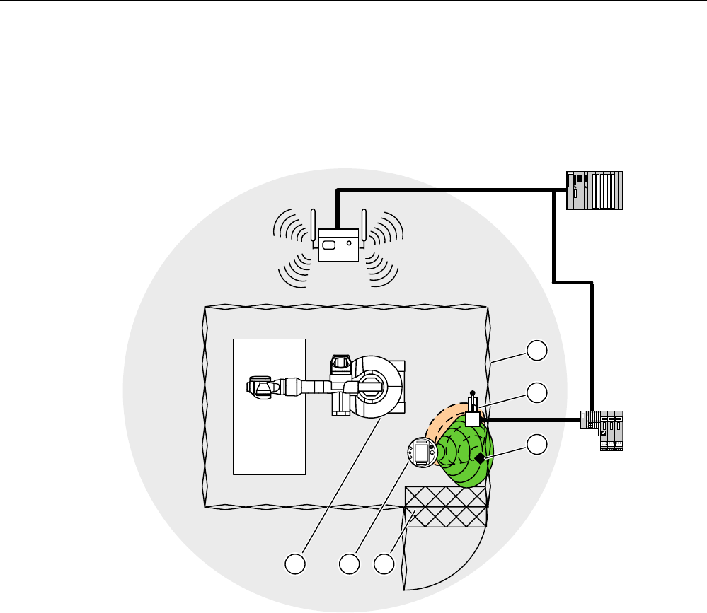
Fail-safe mode
8.6 "Override" mode
Mobile Panel 277F IWLAN
Operating Instructions, 12/2007, A5E01003940-01 227
"Override" mode must only be used in defined system zones that are secured by additional
protective measures, such as a safety gate.
The switch for activating "Override" mode must be inside the protective device, and in an
effective range.
Sample configuration:
352),VDIH
① Safety gate
② Switch for activating "Override" mode
③ Transponder for logging onto the effective range
④ Foot grating for access monitoring
⑤ HMI device
⑥ Machine to be operated
For additional notes on this subject, refer to the System manual "Safety Integrated" and the
Function manual "Fail-safe operation of the Mobile Panel 277F IWLAN".
Requirements for activating "Override" mode
● The system has the protective devices specified for "Override" mode.
● The HMI device is integrated. The "SAFE" LED lights up.

Fail-safe mode
8.6 "Override" mode
Mobile Panel 277F IWLAN
228 Operating Instructions, 12/2007, A5E01003940-01
● The HMI device is logged onto the same effective range in which the override switch
located. The "RNG" LED lights up.
NOTICE
If "Override" mode is activated and you leave the defined system area, "Override" mode
will be automatically deactivated. You must reactivate the override switch when you
return to the defined system area.
Procedure for activating "Override" mode
1. Enter the protection zone.
The protective device is thereby activated.
2. Activate the override switch.
Result
"Override" mode is active.
The "Effective range quality" screen object is displayed entirely in green.
The transponders are not evaluated when forming the effective range. Use the HMI device to
operate the machine as though you were in the middle of the effective range. This approach
applies for the entire override range.
No other HMI device can log onto the effective range.
Requirements for deactivating "Override" mode
"Override" mode is activated.
NOTICE
It is only possible to log back onto this effective range once you have performed the
following actions:
• You have deactivated "Override" mode using the override switch.
• You have logged the HMI device off from the effective range.
The "RNG" LED is off.
Procedure for deactivating "Override" mode
1. Use the override switch to deactivate "Override" mode.
Result
"Override" mode is deactivated. The HMI device is still logged onto the effective range.

Mobile Panel 277F IWLAN
Operating Instructions, 12/2007, A5E01003940-01 231
Operating a project 9
9.1 Starting the project
Requirements
In order to switch on the Mobile Panel 277F IWLAN and start the project, the following
requirements must be met:
● The batteries have been charged and inserted in the HMI device
If the batteries are not available, place the HMI device in the charging station
● The project has been transferred to the HMI device.
● The WLAN quality is sufficient
● Transponders, if effective ranges/zones are configured:
– The transponders are installed
– The batteries are fitted in the transponders
– A unique ID has been set in the transponders that matches the project
parameterization
Switching on the HMI device
Press the ON/OFF button.
The HMI device performs the following steps:
1. The HMI device starts.
2. The "PWR" LED lights up.
3. The "BAT" LED shows the charging status of the inserted main battery.
4. If effective ranges are configured in the project, you will need to perform an acceptance
test when the project is started for the first time.
5. The WLAN connection is established.
Establishing the WLAN connection
SSIDs for up to 3 WLAN networks can be stored in the project.
The WLAN networks stored in the project must be parameterized on the HMI device and
must be included in the list of preferred networks on the HMI device.
The WLAN connection is established as follows:

Operating a project
9.2 Error cases
Mobile Panel 277F IWLAN
232 Operating Instructions, 12/2007, A5E01003940-01
1. If one of the 3 WLAN networks is available when the HMI device is started, the HMI
device connects automatically.
The "COM" LED will flash as long as the WLAN connection is established.
The configured sequence of SSIDs determines the order in which the HMI device will
attempt to connect to the WLAN networks.
2. If the HMI device cannot establish a connection with any of the 3 configured WLAN
networks, the HMI device will attempt to connect to other WLAN networks.
For this to happen, connection to other WLAN networks must be authorized in the project.
3. Once the HMI device has established the WLAN connection, the "COM" LED lights up.
4. If the HMI device was unable to establish a connection with any of the WLAN networks,
Not Connected is displayed in the status line of the dialog box. The project cannot be
started.
Operation
Note
Notes on fail-safe operation
It is imperative that you observe the chapter titled "Fail-safe operation", and in particular the
Organizational measures (Page 219).
Starting the project
When the HMI device is in the Loader, the project can either be started manually using the
"Start" button, or will start automatically, depending on how the project has been configured.
An automatic start occurs either immediately or after a configured delay time.
The following steps are carried out when the project is starting:
1. The HMI device is integrated.
2. The emergency stop button becomes active.
3. The HMI device will show the project start screen or the zone-specific screen.
See also
Acceptance of the system (Page 196)
Integrating the HMI device (Page 222)
9.2 Error cases
During fail-safe operation, you must be aware that the following error cases may arise:

Operating a project
9.2 Error cases
Mobile Panel 277F IWLAN
Operating Instructions, 12/2007, A5E01003940-01 233
Leaving the HMI device logged onto the effective range
CAUTION
Shutdown
Under no circumstances should the effective range be left without an HMI device while the
HMI device is logged onto the effective range.
If the HMI device is in a state where it is constantly ready for operation, the battery will lose
its charge. A flat battery will result in a communication error. The F CPU initiates a
shutdown.
• Log the HMI device off from the effective range.
• Switch off the HMI device if it is not needed. Alternatively, hook the HMI device into the
charging station.
Internal error
If an internal error occurs on the HMI device, the "SAFE" and "RNG" LEDs go out, and the
project is terminated immediately. The HMI device shows a red error display.
Safety functions are no longer available.
Contact the SIEMENS hotline.
Communication error
If a communication error occurs on the HMI device, the "SAFE" LED goes out. Safety
functions are no longer available.
● If the HMI device is logged onto the effective range:
The F CPU initiates a shutdown. The F CPU stops the section of the system that belongs
to the effective range.
● If the HMI device is not logged on to the effective range:
The F CPU initiates a global rampdown.
● If communication is reestablished within 60 seconds:
The emergency stop button becomes active again. The "SAFE" LED lights up again.
Acknowledge the communication error.
If it was logged onto the effective range, the HMI device is logged off. The "RNG" LED
goes out.
● If communication remains interrupted for more than 60 seconds:
The HMI device terminates the project. The "RNG" LED goes out.

Operating a project
9.3 Direct keys
Mobile Panel 277F IWLAN
234 Operating Instructions, 12/2007, A5E01003940-01
9.3 Direct keys
Introduction
Direct keys on the HMI device are used to set bits in the I/O area of a SIMATIC S7.
Direct keys enable operations with short reaction times, that are, for example, a jog mode
requirement.
NOTICE
PLC stop
Please note that leaving the WLAN area will cause the PROFINET IO device to fail and will
therefore result in a PLC stop.
Determine suitable programming measures in the PLC, in order to prevent a PLC stop.
Please refer to your system documentation to check whether additional information on this
subject is available there.
NOTICE
Effectiveness of direct keys in offline mode
Direct keys are active when both of the following conditions are satisfied:
• The HMI device is in an area with sufficient WLAN coverage.
• The HMI device is in "Offline" mode.
NOTICE
If you operate a function key with direct key functionality in a running project, the direct key
function is always executed, independent of the current screen contents.
Direct keys
The following objects can be configured as a direct key:
● Buttons
● Function keys
● Screen numbers
● Handwheel
● Illuminated pushbutton
● Key-operated switch
Note
Direct keys result in additional basic load on the HMI device.
Additional information about direct keys is available in the system manual "WinCC flexible
communication".
Operating a project
9.4 Operator input options
Mobile Panel 277F IWLAN
Operating Instructions, 12/2007, A5E01003940-01 235
9.4 Operator input options
Once the project is transferred to the HMI device, current processes can be operated and
monitored in the process control phase. You have the following options for operating the HMI
device:
● Touch screen
The HMI device is operated by means of the touch screen. The operating elements
shown in the dialogs are touch-sensitive. Touch objects are basically operated in the
same way as mechanical keys. You activate operating elements by touching them with
your finger. To double-click them, touch an operating element twice in succession.
CAUTION
Do not use any pointed or sharp objects when operating the touch screen. Otherwise
this may damage the plastic membrane of the touch screen.
● External input devices
The following operator controls can be connected externally:
– Keyboard, connected via USB
– Mouse, connected via USB
The use of external input devices is recommended for commissioning.
Operating a project with an external keyboard
An external keyboard can be used to operate a project in exactly the same way as with the
HMI keyboard or screen keyboard.
Note
The function keys of the external keyboard are disabled.
Use other keys on the external keyboard, which correspond to the HMI device keys.
Operating a project with an external mouse
An external mouse can be used to operate a project in exactly the same way as with the HMI
touch screen. Click the described operating elements with the mouse.
Operating a project
9.4 Operator input options
Mobile Panel 277F IWLAN
236 Operating Instructions, 12/2007, A5E01003940-01
Unintentional actions
CAUTION
Do not carry out several operations simultaneously. You may otherwise trigger
unintentional actions.
• With touch control:
Always touch only one operating element on the screen
• With key operation via an external keyboard:
Do not press more than two keys simultaneously
Observing the plant documentation
Some operations with the project may require in-depth knowledge about the specific plant on
the part of the operator. Proceed with caution, for example, when you use jog mode. Please
refer to your system documentation to check whether additional information on this subject is
available there.
Operation feedback from operating elements
The HMI device provides optical feedback as soon as it detects that an operating elements
has been selected. The operating element receives the focus and is selected. This selection
is independent of any communication with the PLC. Therefore this selection does not
indicate whether the relevant action is actually executed or not.
The configuration engineer can also configure the selection of an operating element so that it
deviates from the standard. Please refer to your system documentation to check whether
additional information on this subject is available there.
Optical feedback from operating elements
The type of optical feedback depends on the operating element:
● Buttons
The HMI device outputs different views of the "Pressed" and "Unpressed" states,
provided the configuration engineer has configured a 3D effect:
– "Pressed" state:
A "Unpressed" state:

Operating a project
9.5 Function keys
Mobile Panel 277F IWLAN
Operating Instructions, 12/2007, A5E01003940-01 237
The configuration engineer determines the appearance of a marked field, for example,
line width and color for the focus.
● Invisible buttons
By default, invisible buttons are not displayed as pressed when they are touched. No
optical operation feedback is provided in this case.
The configuration engineer may, however, configure invisible buttons so that their outline
appears as lines when touched. This outline remains visible until you select another
operating element.
● I/O fields
When you select an I/O field, the content of the I/O field is displayed against a colored
background. With touch operation, a screen keyboard is displayed for the entering of
values.
9.5 Function keys
Function keys
Function key assignment is defined during configuration. The configuration engineer can
assign function keys globally and locally.
Function keys with global function assignment
A globally assigned function key always triggers the same action on the HMI device or in the
PLC irrespective of the screen displayed. Such an action could be, for example, the
activation of a screen or the closure of an alarm window.
Function keys with local function assignment
A function key with local function assignment is screen-specific and is therefore only
effective within the active screen.
The function assigned locally to a function key can vary from screen to screen.
The function key of a screen can be assigned one function only, either a global or local one.
The local assignment function takes priority over the global setting.
The configuration engineer can assign function keys in such a way that you can operate
operating elements with function keys, for example, the alarm view, trend view, recipe view
or status / PLC.
Multi-key operation
Unwanted actions may be triggered, if the operator unintentionally actuates a key
combination.

Operating a project
9.6 Setting the project language
Mobile Panel 277F IWLAN
238 Operating Instructions, 12/2007, A5E01003940-01
CAUTION
Unintentional actions
In "Online" mode, simultaneous operation of more than two keys may cause unintentional
actions in the plant.
Do not press more than two keys simultaneously.
9.6 Setting the project language
Introduction
The HMI device supports multilingual projects. You must have configured a corresponding
operating element which lets you change the language setting on the HMI device during
runtime.
The project always starts with the language set in the previous session.
Requirements
● The required language for the project must be available on the HMI device
● The language switching function must be logically linked to a configured operating
element such as a button
Selecting a language
You can change project languages at any time. Language-specific objects are immediately
output to the screen in the new language when you switch languages.
The following options are available for switching the language:
● A configured operating element switches from one language to the next in a list
● A configured operating element directly sets the desired language
Please refer to your system documentation to check whether additional information on this
subject is available there.

Operating a project
9.7 Input
Mobile Panel 277F IWLAN
Operating Instructions, 12/2007, A5E01003940-01 239
9.7 Input
9.7.1 Overview
Screen keyboard
When you touch an operating element requiring entry on the HMI device touch screen, a
screen keyboard appears. The screen keyboard is displayed in the following cases:
● An I/O field is selected for input
● A password must be entered for accessing a password-protected function
The screen keyboard is automatically hidden again when input is complete.
Based on the configuration of the operating element, the system displays different screen
keyboards for entering numerical or alphanumerical values.
Note
The screen keyboard display is independent of the configured project language.
General procedure
The operating elements of a screen are operated by touching the touch screen.
Proceed as follows:
1. Touch the desired operating element within the screen.
2. Depending on the operating element, perform further actions. Detailed descriptions can
be found under the respective operating element.
Examples:
– I/O field: Enter numerical, alphanumerical or symbolic values in the I/O field
– Symbolic I/O field: Select an entry from the drop down list box
– Slider control: Move the slider control
Procedure for text boxes
Values are entered in the project text boxes. Based on your configuration, the values are
saved to tags and transferred, for example, to the PLC.
Proceed as follows:
1. Touch the desired text box within the screen.
The screen keyboard opens.
Depending on your configuration, you can enter values in the text box in the following
manner:
– Numerical values, for example decimal numbers, hexadecimal numbers, binary values
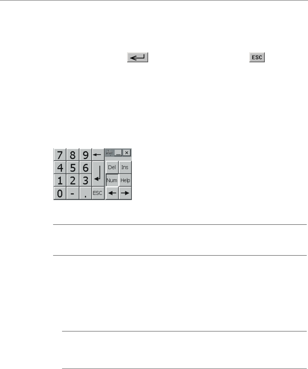
Operating a project
9.7 Input
Mobile Panel 277F IWLAN
240 Operating Instructions, 12/2007, A5E01003940-01
– Alphanumerical values, for example digits and letters
– Date/time
2. Enter the value.
3. Confirm your entry with or discard your entry with the button .
9.7.2 Entering and editing numerical values
Numerical screen keyboard
When you touch an operating element for numerical input on the HMI-device touch screen,
the numerical screen keyboard appears. This is the case, for example, for a text box. The
screen keyboard is automatically hidden again when input is complete.
Figure 9-1 Numerical screen keyboard
Note
Opened screen keyboard
When the screen keyboard is open, PLC job 51, "Select screen" has no function.
Formats for numerical values
You can enter values in numerical text boxes based on the following formats:
● Decimal
● Binary
● Hexadecimal
Note
Entry of hexadecimal values
When you enter values in hexadecimal format, the alphanumerical screen keyboard
opens.

Operating a project
9.7 Input
Mobile Panel 277F IWLAN
Operating Instructions, 12/2007, A5E01003940-01 241
Limit value test of numerical values
Tags can be assigned limit values. If you enter a value that lies outside of this limit, it will not
be accepted, for example, 80 with a limit value of 78. In this case the HMI device will deliver
a system alarm, if an alarm window is configured. The original value is displayed again.
Decimal places for numerical values
The configuration engineer can define the number of decimal places for a numerical text box.
The number of decimal places is checked when you enter a value in this type of I/O field.
● Decimal places in excess of the limit are ignored
● Empty decimal places are filled with "0"
Procedure
Numerical values can be entered character-by-character via the buttons on the numerical
screen keyboard.
Proceed as follows:
1. Touch the desired operating element within the screen.
The numerical screen keyboard opens. The existing value is displayed in the screen
keyboard and is selected.
2. Enter the value.
When entering hexadecimal values, the keys with letters "G" to "Z" are operable, but the
characters will not be entered.
You have the following options to enter a value:
– The selected value is deleted when you enter the first character. Completely reenter
the value.
– Use the and keys to move the cursor within the current value. You can
now edit the characters of the current value or add characters.
Use the key to delete the character to the left of the cursor. If the value is
selected, use this key to delete the selected part of the value.
The key deletes the character positioned to the right of the cursor. If the value is
selected, use this key to delete the selected part of the value.
– Use the key to display the infotext of the I/O field.
This key is only enabled if infotext has been configured for the input object or the
current screen.
3. Use the key to confirm your entry or cancel it with . Either action closes the
screen keyboard.
Result
You have changed the numerical value or entered a new one.
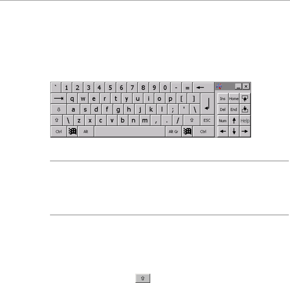
Operating a project
9.7 Input
Mobile Panel 277F IWLAN
242 Operating Instructions, 12/2007, A5E01003940-01
9.7.3 Entering and editing alphanumerical values
Alphanumerical screen keyboard
When you touch an operating element for numerical input on the HMI-device touch screen,
the alphanumerical screen keyboard appears. This is the case, for example, for a text box.
The screen keyboard is automatically hidden again when input is complete.
Figure 9-2 Alphanumerical screen keyboard, normal level
Note
Opened screen keyboard
When the screen keyboard is open, PLC job 51, "Select screen" has no function.
Language change
Language change in the project has no influence on the alphanumerical screen keyboard.
The entry of Cyrillic or Asian chracters is therefore not possible.
Keyboard levels
The alphanumerical screen keyboard has various levels.
● Normal level
● Shift level
If you change the levels with key , the key assignments change.
Procedure
Alphanumerical values can be entered character-by-character via the buttons on the
alphanumerical screen keyboard.
Proceed as follows:
1. Touch the desired operating element within the screen.
The alphanumerical screen keyboard opens. The existing value is displayed in the screen
keyboard and is selected.
2. Enter the value.
You have the following options to enter a value:
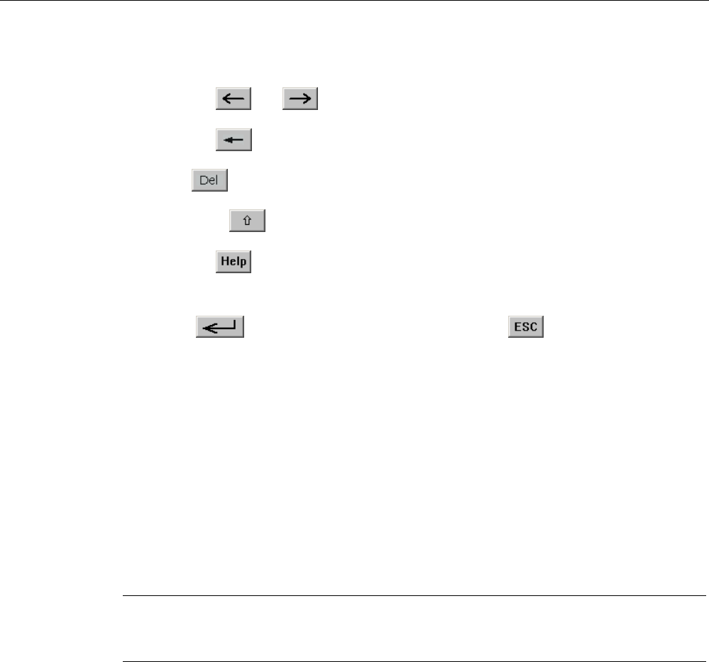
Operating a project
9.7 Input
Mobile Panel 277F IWLAN
Operating Instructions, 12/2007, A5E01003940-01 243
– The selected value is deleted when you enter the first character. Completely reenter
the value.
– Use the and keys to move the cursor within the current value. You can
now edit the characters of the current value or add characters.
Use the key to delete the character to the left of the cursor. If the value is
selected, use this key to delete the selected part of the value.
The key deletes the character positioned to the right of the cursor. If the value is
selected, use this key to delete the selected part of the value.
– Using key it is possible to switch between the keyboard levels of the screen
keyboard. On switchover, the key assignments of the screen keyboard change.
– Use the key to display the infotext of the I/O field.
This key is only enabled if infotext has been configured for the input object or the
current screen.
3. Use the key to confirm your entry or cancel it with . Either action closes the
screen keyboard.
Result
You have changed the alphanumeric value or entered a new one.
9.7.4 Entering the date and time
Entering the date and time
Enter the date and time in the same way you enter alphanumerical values.
Note
When entering the date and time, please note that the format is determined by the
configured project language.
See also
Entering and editing alphanumerical values (Page 242)
Setting the project language (Page 238)
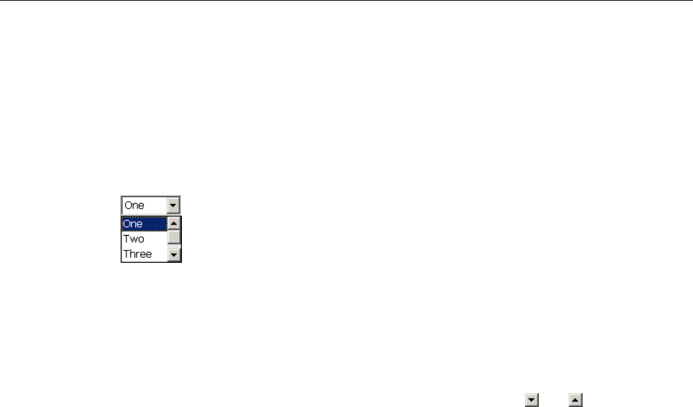
Operating a project
9.8 Displaying infotext
Mobile Panel 277F IWLAN
244 Operating Instructions, 12/2007, A5E01003940-01
9.7.5 Entering symbolic values
Drop down list box
Operating elements for entering symbolic values offer you a list from which you can select
the input values. When you touch a symbolic I/O field on the HMI device touch screen, the
following drop down list box opens.
Figure 9-3 Symbolic I/O field after touch, example
Procedure
Proceed as follows:
1. Touch the required operating element.
The drop down list box of the operating element opens. Select and to scroll in the
drop down list box.
2. Touch the required entry in the drop down list box.
The selected entry is accepted as an entry.
Result
You have changed the symbolic value or entered a new one.
9.8 Displaying infotext
Purpose
The configuration engineer uses infotext to provide additional information and operating
instructions. The configuration engineer can configure infotext on screens and operating
elements.
The infotext of an I/O field may contain, for example, information on the value to be entered.
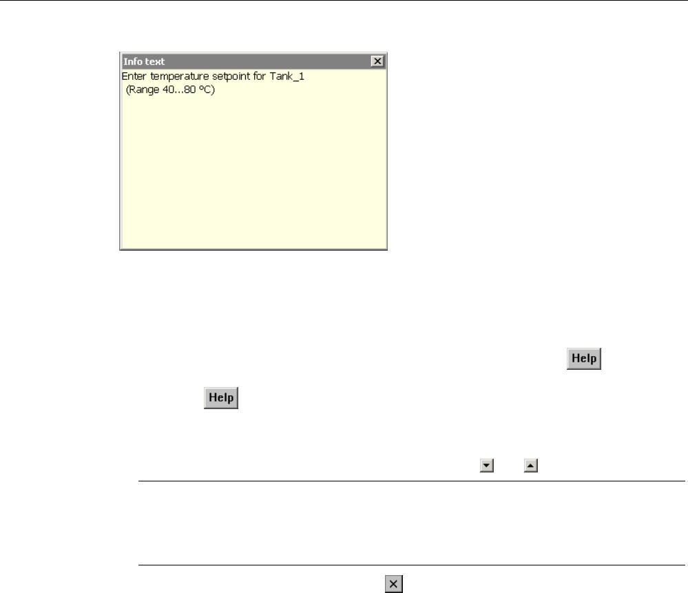
Operating a project
9.8 Displaying infotext
Mobile Panel 277F IWLAN
Operating Instructions, 12/2007, A5E01003940-01 245
Figure 9-4 Infotext for an I/O field, example
Opening infotext for operating elements
1. Touch the required operating element.
The screen keyboard opens. You can see from the appearance of the key whether
infotext has been configured for the operating element or the current screen.
2. Touch the key on the screen keyboard.
The infotext for the operating element is displayed. If there is no infotext for the selected
screen object, the infotext for the current screen is displayed, if it has been configured.
You can scroll through the contents of long infotext with and .
Note
Switching between displayed infotext
The configuration engineer can configure infotext for an I/O field and the associated
screen. You can switch between two infotexts by touching the infotext window.
1. Close the displayed infotext by pressing .
Alternative procedure
Depending on your configuration, infotext can also be called via a configured operating
element.
Please refer to your system documentation to check whether additional information on this
subject is available there.
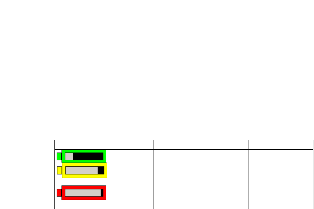
Operating a project
9.9 Device-specific displays
Mobile Panel 277F IWLAN
246 Operating Instructions, 12/2007, A5E01003940-01
9.9 Device-specific displays
9.9.1 Displaying battery status
Application
The "Battery" object indicates the charging status of the main battery. Charge the battery in
good time. Alternatively, change the main battery.
Layout
Symbol Color Meaning Charging status
Green The battery is sufficiently charged. >20 %
Yellow The battery is weak. The battery
must be charged. Alternatively,
insert a charged spare battery.
10 % to 20 %
Red Battery is very weak. The battery
must be charged. Alternatively,
insert a charged spare battery.
<10 %
Operation
The object is for display only and cannot be operated.
9.9.2 Displaying WLAN quality
Application
The "WLAN quality" object displays the signal strength of the WLAN wireless connection.
The HMI device measures the signal strength and indicates the quality using 5 bars.
Layout

Operating a project
9.9 Device-specific displays
Mobile Panel 277F IWLAN
Operating Instructions, 12/2007, A5E01003940-01 247
Symbol Meaning Signal strength
No wireless connection No signal
Very poor wireless connection ≤20 %
Poor wireless connection ≤40 %
>20 %
Wireless connection OK ≤60 %
>40 %
Good wireless connection ≤80 %
>60 %
Very good wireless connection >80 %
Operation
The "WLAN quality" object is purely for display purposes. You cannot operate the "WLAN
quality" object.
9.9.3 Displaying the effective range name
Application
The "Effective range name" object indicates the following:
● Name of the effective range in which the HMI device is currently located.
● Logon status
Layout
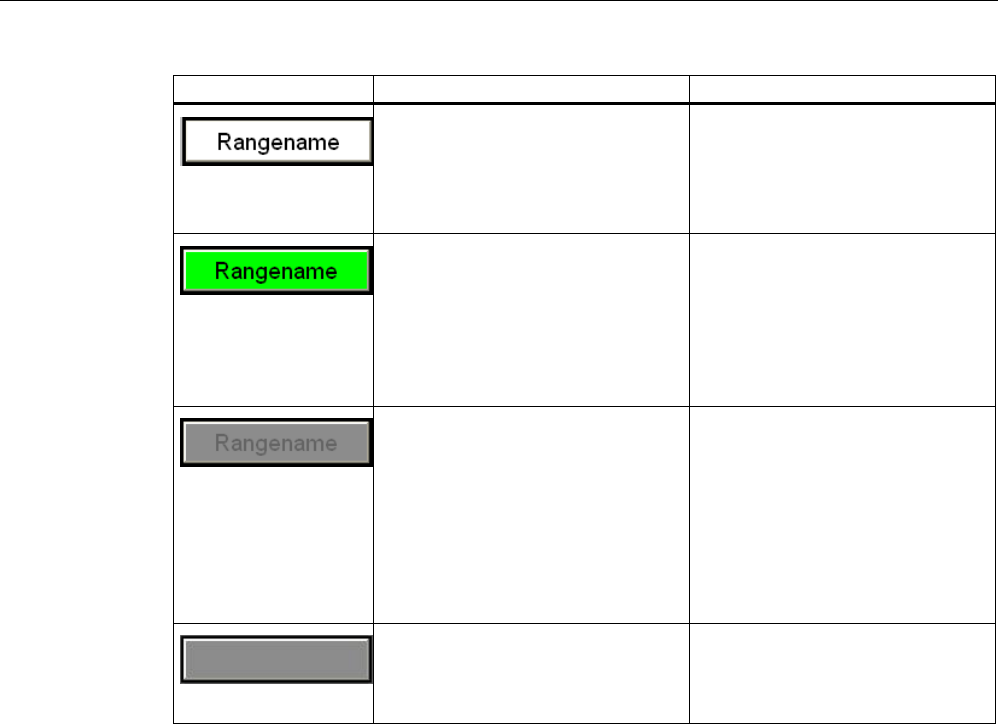
Operating a project
9.9 Device-specific displays
Mobile Panel 277F IWLAN
248 Operating Instructions, 12/2007, A5E01003940-01
Symbol Description Logon
The HMI device is within the effective
range shown.
The HMI device is not logged onto
the effective range.
The enabling button is not active.
It is possible to log onto the effective
range.
The HMI device is within the effective
range shown and is logged onto the
effective range.
Using the enabling buttons, safe
operation in the effective range is
possible
.
The HMI device is logged onto the
effective range.
The HMI device is within the effective
range shown.
The enabling button is not active.
Logon to the effective range is
rejected because a different HMI
device is already logged on.
Note:
When using the "Override" mode:
Although no other HMI device is still
logged on to the effective range,
logon is rejected because the
override switch is still set.
The HMI device is outside all of the
effective ranges.
The enabling button is not active.
It is not possible to log onto the
effective range.
Note: You can only log on within the
effective range
See also
Logging onto and off from the effective range (Page 224)
9.9.4 Displaying the effective range quality
Application
The "Effective range quality" object indicates how accurately the Mobile Panel 277F IWLAN
is still within an effective range. In contrast to the "WLAN quality" object, the HMI device
does not measure signal strength. The HMI device calculates the effective range quality on
the basis of the distance between it and the assigned transponders.
The "Effective range quality" is then also updated if the HMI device is not logged onto the
effective range.
Layout
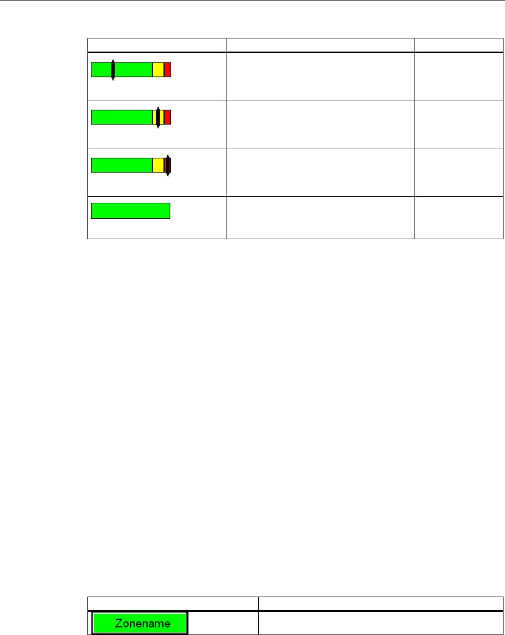
Operating a project
9.9 Device-specific displays
Mobile Panel 277F IWLAN
Operating Instructions, 12/2007, A5E01003940-01 249
Symbol Meaning Quality
The HMI device is in the middle of the
effective range.
>15 %
The HMI device is at the limits of an effective
range.
1% to 15%
The HMI device is not within the effective
range.
0 %
"Override" mode is active. The distance of
the HMI device to the transponders is not
evaluated. "Override" mode (Page 226)
–
The "Effective range name" object indicates which effective range this concerns.
Calculating the quality
The quality within an effective range depends on the measured distance to the transponder,
as shown below:
● In the center of the effective range the quality is 100%.
● The quality decreases as you approach the limits of the effective range.
● On the transponder and on the border of the effective range, the quality is 0%.
Operation
The object is for display only and cannot be operated.
9.9.5 Displaying zone names
Application
The "Zone name" object shows the names of the zone in which the HMI device is currently
located.
Layout
Symbol Meaning
The HMI device is within the indicated zone.
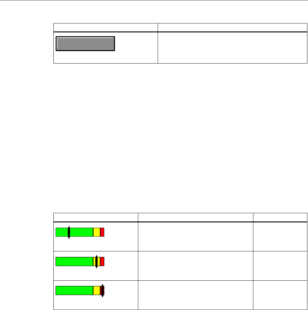
Operating a project
9.9 Device-specific displays
Mobile Panel 277F IWLAN
250 Operating Instructions, 12/2007, A5E01003940-01
Symbol Meaning
The HMI device is not inside any zone.
Operation
The "Zone name" object is purely for display purposes. You cannot operate the "Zone name"
object.
9.9.6 Displaying zone quality
Application
The "Zone quality" object shows how close the HMI device is to the limits of a zone. Unlike
with "WLAN quality", the HMI device does not measure signal strength. The HMI device
calculates the zone quality from the distance between it and the assigned transponders.
Layout
Symbol Meaning Quality
The HMI device is within a zone. >15 %
The HMI device is at the limits of a zone. 1% to 15%
The HMI device is not within any zone. 0 %
The "Zone quality" object indicates which zone this concerns.
Calculating the quality
The quality within a zone depends on the measured distance to the transponder:
● In the center of the zone the quality is 100%
● The quality decreases as you approach the limits of the zone
● On the transponder and on the border of the zone, the quality is 0%
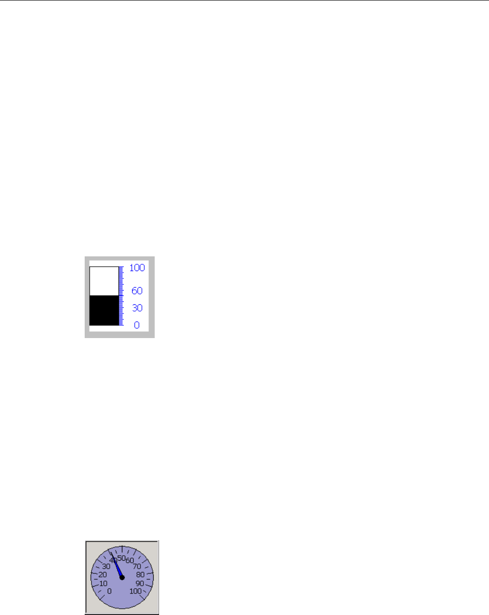
Operating a project
9.10 Bar and gauge
Mobile Panel 277F IWLAN
Operating Instructions, 12/2007, A5E01003940-01 251
Operation
The "Zone quality" object is purely for display purposes. You cannot operate the "Zone
quality" object.
9.10 Bar and gauge
Bar
The bar is a dynamic display object. The bar displays a value from the PLC as a rectangular
area. The bar allows you to recognize the following at a glance:
● The distance of the current value from the configured limit values
● Whether a set point value has been reached
The bar can display values such as fill levels or batch counts.
Layout
The layout of the bar depends on the configuration:
● The bar may feature a scale of values
● The configured limit values can be indicated by lines
● Color changes can signal when a limit value has been exceeded or has not been reached
Gauge
The gauge is a dynamic display object. The gauge displays numerical values in analog form
by means of a pointer. This enables an operator at the HMI device to see at a glance if the
boiler pressure is in the normal range, for example.
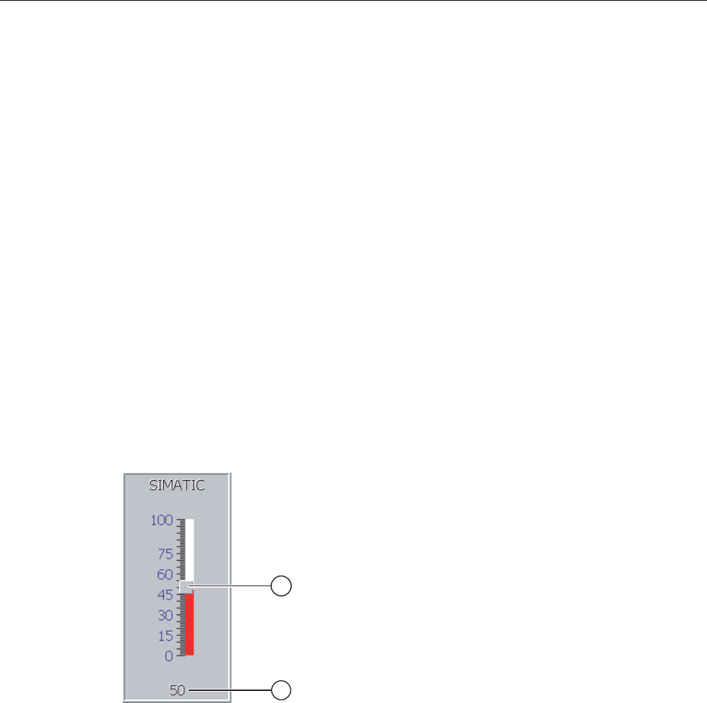
Operating a project
9.11 Operating the slider control
Mobile Panel 277F IWLAN
252 Operating Instructions, 12/2007, A5E01003940-01
Layout
The layout of the gauge depends on the configuration:
● A trailing pointer can display the maximum value reached so far on the scale. The trailing
pointer is reset when the screen is reloaded
● The label on the scale can show the measured variable, for example boiler pressure and
the physical unit, for example bar
Operation
The bar and the gauge are for display only. Both objects cannot be controlled by the
operator.
9.11 Operating the slider control
Introduction
The slider control can be used to monitor and change process values within a defined range.
The slider control can also be configured without a slider. In this case, you cannot enter a
value. The slider control is then only used for displaying values.
Figure 9-5 Slider control – example
① Slider control for entering values
② Value display with current value
Layout
The layout of the slider control depends on the configuration:
● The slider control can contain a label and a setting range
● The current value can be displayed below the area of the slider control
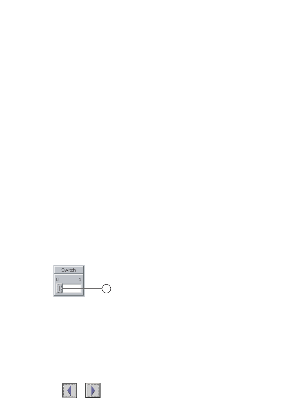
Operating a project
9.12 Operating the switch
Mobile Panel 277F IWLAN
Operating Instructions, 12/2007, A5E01003940-01 253
Procedure
Proceed as follows:
1. Touch the slider of the desired slider control.
2. Move the slider to the required value.
If a value display has been configured, you can check the exact value that has been set.
3. Release the slider.
Result
The set value is applied.
9.12 Operating the switch
Introduction
The switch is an operating element and display object with two predefined switching states,
for example "On" and "Off". Switches can signalize the state of a plant section, for example if
a motor is running or not. At the same time, you can use the switch to change the state of
the corresponding plant section via the HMI device, for example from "On" to "Off".
Layout
The layout of the switch depends on the configuration:
● Switch with slider
The two states are displayed by the position of the slider
① Slider
● Switch with text or graphic
The two states are displayed by the label on the slider
Depending on the switching state, the switch is labeled with one of two texts or one of two
graphics.
Examples:
"Backward" or "Forward"
or
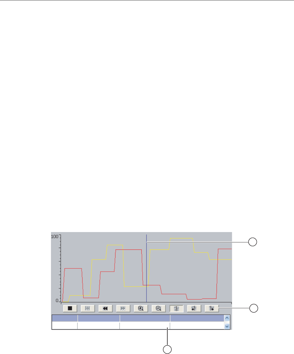
Operating a project
9.13 Operating the trend view
Mobile Panel 277F IWLAN
254 Operating Instructions, 12/2007, A5E01003940-01
Procedure
● Switch with slider
Proceed as follows:
Move the slider to the other position or double-click the slider area
● Switch with text or graphic
Proceed as follows:
Touch the switch
Result
The switch changes its appearance. The associated value is switched.
9.13 Operating the trend view
Trends
Trends continuously display the current process data or process data from a log.
Trend view
Trends are displayed in the trend view. A trend view can display several trends
simultaneously.
9DOXH7DJDVVLJQPHQW7UHQG 'DWH WLPH
3UHVVXUHSDWWHUQ3UHVVXUH
Figure 9-6 Trend view, example
① Ruler
② Buttons for trend operation

Operating a project
9.13 Operating the trend view
Mobile Panel 277F IWLAN
Operating Instructions, 12/2007, A5E01003940-01 255
③ Trend value in the value table
Layout and operation
The layout and operation of the trend view depends on the configuration. The configuration
engineer determines, for example, the following:
● Appearance of the trend view, the axes, value ranges and labels
● Operating options of the trend view
● Limit values for the trend values
● The change of color of the trend in the event of limit violation
Please refer to your system documentation to check whether additional information on this
subject is available there.
Value table
The trend values can be read from the value table if this is configured:
● When the ruler is displayed, the trend values are shown at a position of the ruler in the
value table
● When the ruler is hidden, the latest trend values are displayed in the value table
Ruler
When configured, a ruler is available to provide an exact reading of the trend values in the
value table.
You can move the ruler to the desired position of the trend view.
Operation
The trend view can be operated as follows:
● Enlarge or reduce the time interval displayed
● Scroll forward or back by one display width
● Stop and resume trend recording
● Move the ruler
● Hide and display the ruler
The following table shows the trend view buttons:
Buttons Functions
Stops or continues trend recording.
Enlarges the displayed time section.
Reduces the displayed time section.
Scrolls one display width backwards (to the left)
Scrolls one display width forwards (to the right)
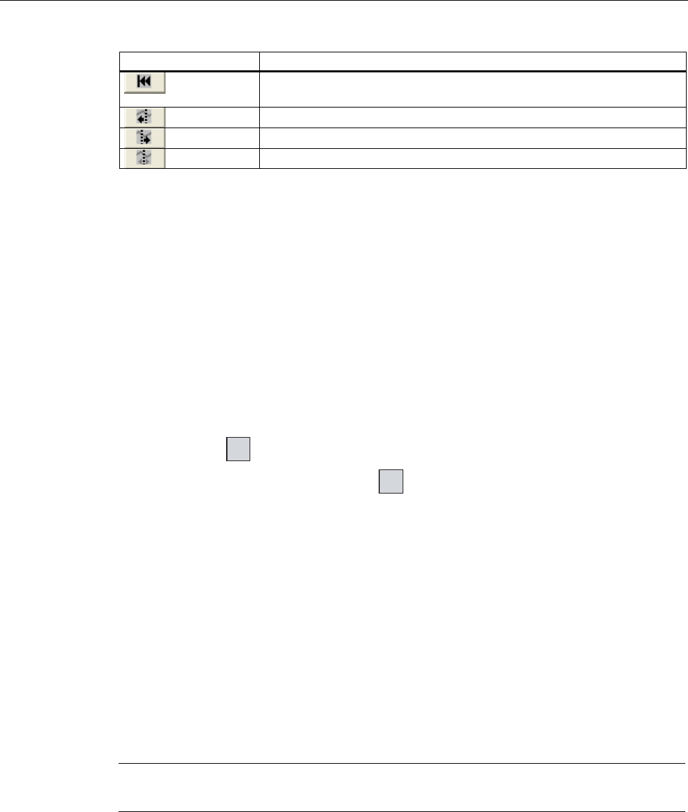
Operating a project
9.14 Operating the Status Force
Mobile Panel 277F IWLAN
256 Operating Instructions, 12/2007, A5E01003940-01
Buttons Functions
Scrolls back to the beginning of the trend recording. The start values of the
trend recording are displayed there.
Moves the ruler backwards (to the left)
Moves the ruler forwards (to the right)
Shows or hides the ruler.
In addition, the configuration engineer can configure function keys or operating elements
with which you can control trend views.
Please refer to your system documentation to check whether additional information on this
subject is available there.
Touch operation
Touch the required button in the trend view.
The position of the ruler can also be changed by means of touching and dragging the ruler
on the touch screen.
Procedure using the keys
Proceed as follows:
1. Using the key TAB select the desired button within the trend view.
2. Confirm your entry by pressing the key
ENTER
.
9.14 Operating the Status Force
9.14.1 Overview
Application
You read or write access values of the connected PLC directly with Status Force. Status
force allows you to monitor or change addresses of the PLC program, etc. You don't need to
connect an additional programming device or additional PC to the PLC.
Note
Status force can only be used in combination with SIMATIC S7.
Layout
The layout of Status Force depends on the configuration.
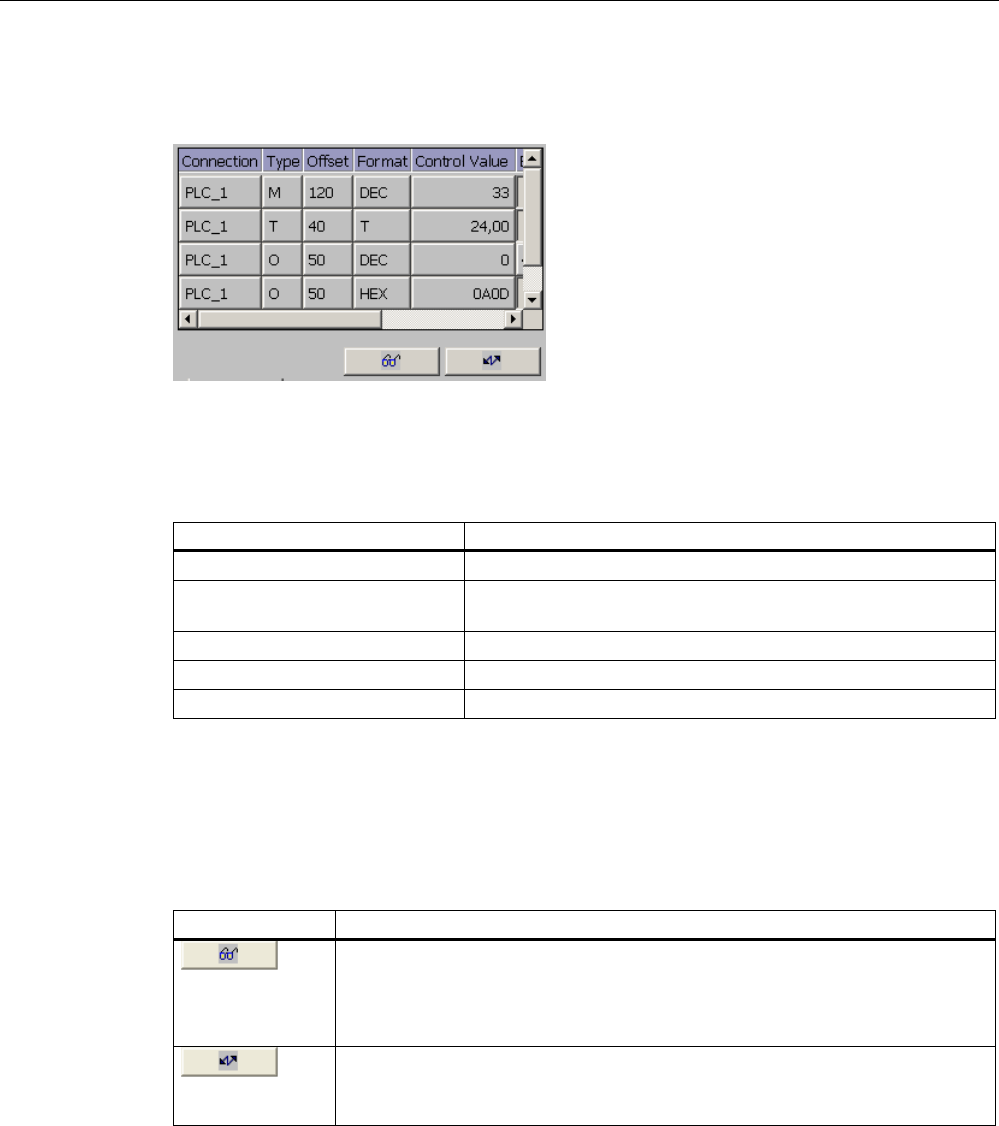
Operating a project
9.14 Operating the Status Force
Mobile Panel 277F IWLAN
Operating Instructions, 12/2007, A5E01003940-01 257
The figure shows the general layout of Status Force. A value can be monitored or controlled
on every line.
Figure 9-7 Status Force, example
The configuration engineer specifies which columns appear in Status Force.
The table shows the significance of all configurable columns.
Column Functions
"Connection" The PLC whose address ranges must be displayed.
"Type", "DB Number", "Offset",
"Bit"
The address range of the value
"Data type", "Format" The data type of the value
"Status value" The value read from the specified address.
"Control value" The value to be written to the specified address.
Please refer to your system documentation to check whether additional information on this
subject is available there.
Operator controls
Depending on your configuration, you can operate the trend view using the following buttons:
Buttons Functions
"Read" button
Updates the display in the "Status value" column.
This button engages when it is pressed. You cannot operate any text boxes until
the button is actuated again and the refresh is stopped.
"Write" button
Applies the new value in the "Control value" column. The control value is written
to the PLC.

Operating a project
9.14 Operating the Status Force
Mobile Panel 277F IWLAN
258 Operating Instructions, 12/2007, A5E01003940-01
9.14.2 Operation
Operator input options
Status Force can be operated as follows:
● Change the column sequence
● Read the status values of the connected PLC
● Enter values and transfer them to the PLC
Change column sequence
Depending on the configuration, you can change the column sequence of Status Force.
Proceed as follows:
1. Touch the column header which you wish to exchange with a different column header
2. Keeping the touch screen pressed, move the column heading to the column heading you
wish to exchange it with
Result
The columns are displayed in the modified sequence.
Procedure for reading the status value
Proceed as follows:
1. Enter the address and the desired format of a value for each line. Touch the respective
columns to display the screen keyboard.
2. Once you have entered all of the desired values, touch the button.
Result
All values are read cyclically by the PLC and entered in the "Status value" column until the
button is touched again.
Requirements for forcing
The following requirements must be fulfilled in order to force values:
● The "Control value" column must be available
● The "Write" button must be available
Procedure for forcing a value
Proceed as follows:
1. Enter the address of a value for each line. Enter the desired value in the "Control value"
column. Touch the respective columns to display the screen keyboard.

Operating a project
9.15 Operating the Sm@rtClient view
Mobile Panel 277F IWLAN
Operating Instructions, 12/2007, A5E01003940-01 259
2. Once you have entered all of the desired values, touch the button.
Result
The values from the "Control value" column are transferred once to the PLC.
9.15 Operating the Sm@rtClient view
9.15.1 Overview
Application
The Sm@rtClient view enables you to monitor and remotely operate the current project of a
remote HMI device. With the correct configuration, several equal priority HMI devices can
access a remote HMI device.
Note
If another HMI device accesses your HMI device via the Sm@rtClient view, this leads to an
additional load on your HMI device.
Layout
In the Sm@rtClient view, the remote HMI is displayed with the complete layout.
Depending on the configuration, you can monitor and also operate this screen.
You can also operate the function keys like buttons on an HMI device with a touch screen.
Monitoring mode
On a Sm@rtClient view which is configured for monitoring mode, you can only monitor the
remote HMI device. You cannot control its operation.
Operation
Note
It is not possible to operate the direct keys of the remote HMI device from the local HMI
device.
The available operator controls depend on the HMI devices used:
● Same type of HMI devices

Operating a project
9.15 Operating the Sm@rtClient view
Mobile Panel 277F IWLAN
260 Operating Instructions, 12/2007, A5E01003940-01
You can operate the project of the remote HMI device with the operator controls of your
HMI device
● Operate keys from a local touch screen
All the keys of the remote HMI device are displayed as buttons on the touch screen. You
can also touch them to operate them
● Touch operation from a local HMI device using keys
You operate the buttons in the usual manner.
9.15.2 Operation
Operator input options
The Sm@rtClient view can be operated as follows:
● Starting remote control
● Forcing permission
● Ending remote control
Procedure for starting remote control
Proceed as follows:
1. On the HMI device change to the screen with the Sm@rtClient view.
The following options are available for establishing the connection to the remote HMI
device:
– The connection is established automatically.
– The connection must be established by touching the appropriate button.
Depending on the configuration, you may be required to enter the address of the
remote HMI device and a password.
2. The current screen of the project running on the remote device is displayed on the screen
of your HMI device.
3. You can now monitor and control this screen depending on your configuration.
Scroll bars are displayed if the screen of the remote HMI device is larger than that of the
current HMI device.
Procedure for forcing permission
If several HMI devices have access to a HMI device, only one HMI device has operating
permission at any one time.
Two cases must be distinguished for this case:
● If another HMI device is already controlling the remote HMI device, if configured
accordingly, you can force operating permission for the remote HMI device
– You are trying to operate the remote HMI device

Operating a project
9.16 Project security
Mobile Panel 277F IWLAN
Operating Instructions, 12/2007, A5E01003940-01 261
– A dialog appears in which you are prompted to enter the appropriate password for
forcing remote control
– You are now authorized to operate the remote HMI device
● If another HMI device is accessing your HMI device via the Sm@rtClient view, you can
force local operating permission for your HMI device
– Touch the screen of your HMI device five times consecutively
– You are given permission to operate your local HMI device
Procedure for ending remote control
You can end monitoring and control of a remote HMI device with one of the following
methods depending on the configuration:
● Touch a button configured for this action
● Exit the screen containing the Sm@rtClient view
● If configured, a menu is displayed after you have touched an empty space over a longer
period. Select the "Close" menu item.
Please refer to your system documentation to check whether additional information on this
subject is available there.
9.16 Project security
9.16.1 Overview
Design of the security system
The configuration engineer can protect the operation of a project by implementing a security
system.
The security system is based on authorizations, user groups and users.
If operating elements protected by a password are pressed, the HMI device first requests
that you log on. A logon screen is displayed in which you enter your user name and
password. After logging on, you can press the operating elements for which you have the
necessary authorizations.
The logon dialog can be set up by the configuration engineer via an individual operating
element.
In the same way, the configuration engineer can set up an operating element to log off. After
logging off, objects assigned password protection can no longer be operated; to do so, log
on again.
Please refer to your system documentation to check whether additional information on this
subject is available there.

Operating a project
9.16 Project security
Mobile Panel 277F IWLAN
262 Operating Instructions, 12/2007, A5E01003940-01
Central user administration using SIMATIC Logon
Users, user groups and authorizations can be stored on a central server.
If user administration cannot contact the server, an error message is displayed. If this is the
case, you can only log on locally. Check whether additional information is available in your
plant documentation.
The operation of SIMATIC Logon differs as follows:
● The simple user display is not supported
● Users cannot be deleted
● You cannot change your logout time
● When changing the password, you must enter it twice for security reasons
● The domain name is also indicated in the "User" field
User groups and authorizations
Project-specific user groups are created by the configuration engineer. The "Administrators"
and "PLC User" groups are included in all projects by default. User groups are assigned
authorizations. Authorization required for an operation is specifically defined for each
individual object and function in the project.
Users and passwords
Each user is assigned to exactly one user group.
The following persons are allowed to create users and assign them passwords:
● The configuration engineer during configuration
● The administrator on the HMI device
● A user with user management authorization on the HMI device
Irrespective of the user group, each user is allowed to change his own password.
Logoff times
A logoff time is specified in the system for each user. If the time between any two user
actions, such as entering a value or changing screens, exceeds this logoff time, the user is
automatically logged off. The user must then log on again to continue to operate objects
assigned password protection.
Backup and restore
Note
Backup and restore is not available to central user administration with SIMATIC Logon.
The user data is encrypted and saved on the HMI device to protect it from loss due to power
failure.
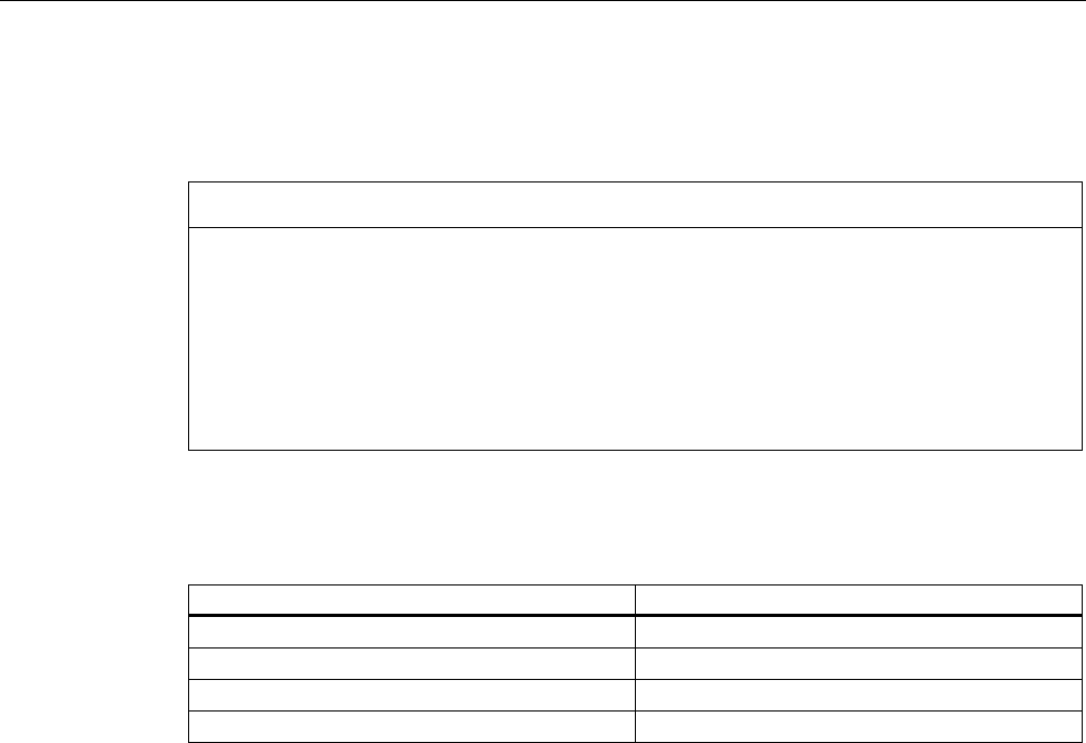
Operating a project
9.16 Project security
Mobile Panel 277F IWLAN
Operating Instructions, 12/2007, A5E01003940-01 263
The users, passwords, group assignments and logoff times set up on the HMI device can be
backed up and restored. This prevents you having to enter all of the data again on another
HMI device.
NOTICE
The currently valid user data is overwritten in the following cases:
• Depending on the transfer settings, when the project is transferred again
• Upon restore of a backed-up project
• Upon import of the user administration via an operating element. Please refer to your
system documentation to check whether additional information on this subject is
available there.
The retransferred or restored user data and passwords are valid with immediate effect.
Limits for user, password and user view
Number of characters
Length of user name, maximum 40
Length of password, minimum 3
Length of password, maximum 24
Entries in user view, maximum 50
9.16.2 User view
Application
The user view is used to display the users on the HMI device:
● All users on the HMI device are displayed in the user view to the administrator or to a
user with administrator authorizations
● If you are a user without user management authorization, you can only see your personal
user entry
The authorizations of a user after logging on depends on the user group to which the user is
assigned.
Please refer to your system documentation to check whether additional information on this
subject is available there.
Layout
The configuration engineer can implement a simple or extended user view.
The two user views offer the same functions. They differ only in the display of information.
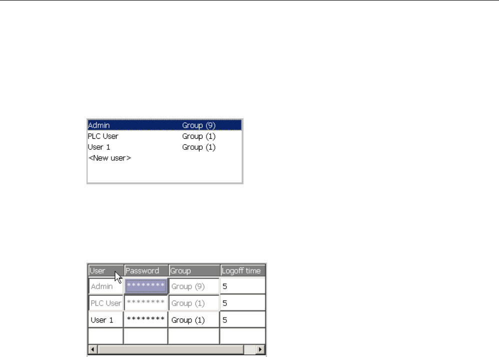
Operating a project
9.16 Project security
Mobile Panel 277F IWLAN
264 Operating Instructions, 12/2007, A5E01003940-01
Simple user view
If you are not logged on to the HMI device, the only entry contained in the simple user view
is "<ENTER>".
If you are logged on to the HMI device, the simple user view only displays the user name
and user group.
Extended user view
The extended user view displays information about the users.
The extended user view contains the following columns:
● Users
● Password
● Group
● Logoff time
The passwords are encrypted by appearing as asterisks.
9.16.3 User logon
Logon dialog
Use the logon dialog to log on to the security system of the HMI device. Enter your user
name and password in the logon dialog.
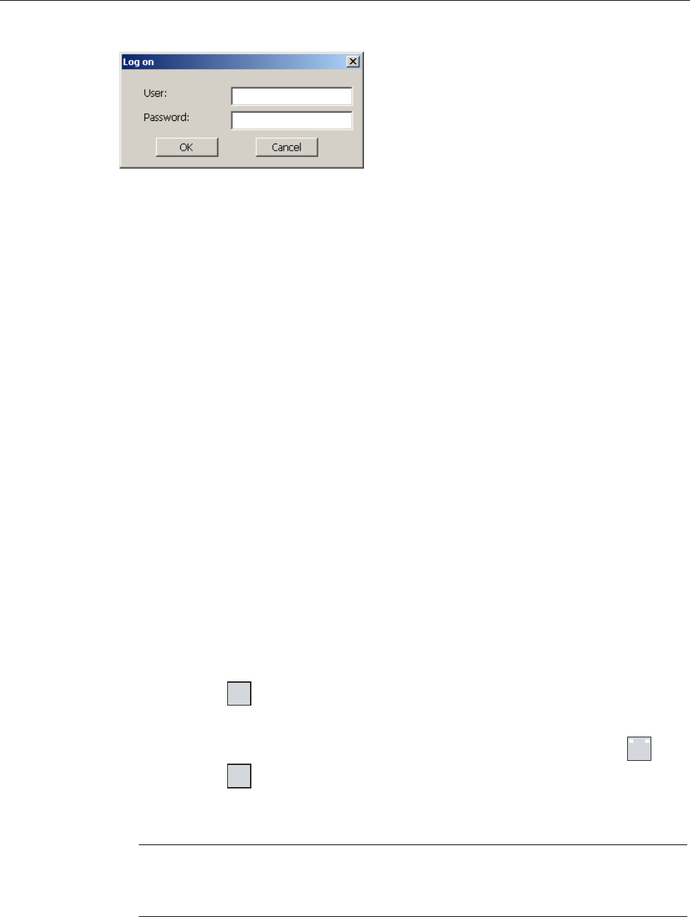
Operating a project
9.16 Project security
Mobile Panel 277F IWLAN
Operating Instructions, 12/2007, A5E01003940-01 265
The logon dialog opens in the following cases:
● You press an operating element with password protection
● You press an operating element that was configured for displaying the logon dialog
● Select the "<ENTER>" entry in the simple user view
● Select a blank entry in the extended user view
● The logon dialog will be automatically displayed when the project is started, depending on
the configuration
Please refer to your system documentation to check whether additional information on this
subject is available there.
Requirements
The logon dialog is open.
Procedure using the touch screen
Proceed as follows:
1. Enter the user name and password.
Touch the corresponding text box. The alphanumerical screen keyboard is displayed.
2. Select "OK" to confirm logon.
Procedure using the keys
Proceed as follows:
1. Using the key TAB select the "User" text box within the logon dialog.
2. Enter the user name using the system keys.
To enter letters, switch the numerical keypad to letter assignment using the key A-Z .
3. Using the key TAB select the "Password" text box.
4. Enter the password using the system keys.
5. Touch the "OK" button to confirm your entries.
Note
The user name is not case-sensitive.
The password is case-sensitive.

Operating a project
9.16 Project security
Mobile Panel 277F IWLAN
266 Operating Instructions, 12/2007, A5E01003940-01
Result
After successful logon to the security system, you can execute password-protected functions
on the HMI device for which you have authorizations.
If you enter a wrong password, an error message is displayed when an alarm window has
been configured.
9.16.4 User logoff
Requirements
You have logged into the security system of the HMI device.
Procedure
You have the following options for logging off:
● You press an operating element that was configured for logoff
● You will be logged off automatically if you are not operating the project and if the logoff
time has been exceeded
You will also be automatically logged off if you enter an incorrect password.
Result
You are no longer logged into the project. In order to activate an operating element with
password protection, you must first log on again.
9.16.5 Creating users
Requirements
You have opened a screen containing the user view.
You have user management authorization or you are the administrator.
NOTICE
The following characters cannot be used in passwords:
• Blank
• Special characters * ? . % / \ ' "
Procedure for creating a user in the simple user view
Proceed as follows:
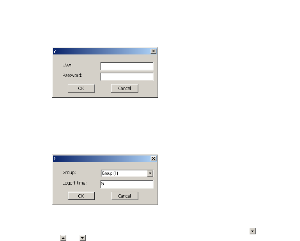
Operating a project
9.16 Project security
Mobile Panel 277F IWLAN
Operating Instructions, 12/2007, A5E01003940-01 267
1. Touch the "<New User>" entry in the user view.
The following dialog opens:
1. Enter the desired user name and password.
Touch the corresponding text box. The alphanumerical screen keyboard is displayed.
2. Touch the "OK" button.
The following dialog opens:
1. Assign the user to a group.
In order to do so, open the "Group" drop down list box by means of the button. Select
and to scroll in the drop down list box.
2. Touch the required entry in the drop down list box.
The selected entry is then accepted as input.
3. Touch the text box "Logoff time". The screen keyboard is displayed.
4. Enter a value between 0 and 60 for the logoff time in minutes. The value 0 stands for "no
automatic logoff."
5. Touch the "OK" button to confirm your entries.
Procedure for creating a user in the extended user view
Proceed as follows:
1. Double-click the desired field in the blank line of the user view.
The appropriate screen keyboard is displayed.
2. Enter the respective user data in the field:
– Assign the user to one of the groups from the drop down list box.
– Enter a value between 0 and 60 for the logoff time in minutes. The value 0 stands for
"no automatic logoff."

Operating a project
9.16 Project security
Mobile Panel 277F IWLAN
268 Operating Instructions, 12/2007, A5E01003940-01
Result
The new user is created.
9.16.6 Changing user data
Requirements
You have opened a screen containing the user view.
Which data you are allowed to change depends on your authorization:
● You are an administrator or a user with user management authorization. In these cases
you are allowed to change the data for all the users on the HMI device in the user view:
– User name
– Group assignment
– Password
– Logoff time
● You are a user without user management authorization. In this case you are only allowed
to change your personal user data:
– Password
– Logoff time, if configured
Note
You can only change the logoff time and password for the "Admin" user.
You can only change the logoff time for the "PLC_User". This user is used for logging
on via the PLC
Procedure for changing user data in the simple user view
Proceed as follows:
1. In the user view, touch the user whose user data you want to change
2. When entering the data, use exactly the same procedure as for creating a user
Procedure for changing user data in the extended user view
Proceed as follows:
1. In the user view, touch the user whose user data you want to change
2. When entering the data, use exactly the same procedure as for creating a user
Result
The user data for the user is changed.

Operating a project
9.17 Closing the project
Mobile Panel 277F IWLAN
Operating Instructions, 12/2007, A5E01003940-01 269
9.16.7 Deleting users
Requirements
You have opened a screen containing the user view.
To delete a user, you must be an administrator or have user management authorization.
Note
The "Admin" and "PLC_User" users exist by default. These users cannot be deleted.
Procedure
To delete a user, delete the user name entered.
Result
The user has been deleted and may no longer log onto the project.
9.17 Closing the project
Procedure
Proceed as follows:
1. If "Override" mode has been activated, deactivate it.
2. If you are logged onto the effective range, log off from it.
3. Use the corresponding operating element object to close the project. Alternatively, press
and hold the ON/OFF button for at least 4 seconds.
The "Confirm removal" dialog box is displayed.
4. Press the enabling button to confirm the dialog box.
The HMI device is removed.
Wait for the Loader to open after you closed the project.
Result
The project is terminated.
Mobile Panel 277F IWLAN
Operating Instructions, 12/2007, A5E01003940-01 271
Operating alarms 10
10.1 Overview
Alarms
Alarms indicate events and states on the HMI device which have occurred in the system, in
the process or on the HMI device itself. A status is reported when it is received.
An alarm could trigger one of the following alarm events:
● Incoming
● Outgoing
● Acknowledge
The configuration engineer defines which alarms must be acknowledged by the user.
An alarm may contain the following information:
● Date
● Time
● Alarm text
● Location of fault
● State
● Alarm class
● Alarm number
● Alarm group
● Diagnostics capability
Alarm classes
Alarms are assigned to various alarm classes:
● Error
Alarms in this class must always be acknowledged. Error alarms normally indicate critical
errors within the plant such as "Motor temperature too high"
● Operation
Warning alarms usually indicate states of a plant such as "Motor switched on"
● System

Operating alarms
10.2 Recognizing pending alarms
Mobile Panel 277F IWLAN
272 Operating Instructions, 12/2007, A5E01003940-01
System alarms indicate states or events which occur on the HMI device
● SIMATIC diagnostic alarms
SIMATIC diagnostic alarms show states and events of the SIMATIC S7 or SIMOTION
PLCs
● User-specific alarm classes
The properties of this alarm class must be defined in the configuration
Please refer to your system documentation to check whether additional information on this
subject is available there.
Alarm groups
The configuration engineer can group alarms into alarm groups. When you acknowledge an
individual alarm of an alarm group, you acknowledge all alarms which belong to the same
alarm group.
Alarm buffer
The alarm events are stored in an internal buffer. The size of this alarm buffer depends on
the HMI device type.
Alarm report
The configuration engineer can activate alarm reporting on the project. In this case, alarm
events are output directly on the connected printer.
The configuration engineer can define whether each individual alarm is logged. An alarm of
this type is printed when the alarm events "Incoming" and "Outgoing" occur.
If you want to print alarms of the "System" alarm class, you have to print the contents of the
associated alarm buffer. For this case the configuration engineer has to configure an
operating element for printing the alarm buffer.
Alarm log
Alarm events are stored in an alarm log, provided this log file is configured. The capacity of
the log file is limited by the storage medium and system limits.
10.2 Recognizing pending alarms
You can recognize pending alarms that must be acknowledged by means of the alarm
indicator.
The alarm indicator is a graphic symbol indicating pending alarms or alarms requiring
acknowledgment, depending on the configuration. The configuration determines whether an
alarm has to be acknowledged or not. This is also defined by the alarm class which an alarm
belongs to.
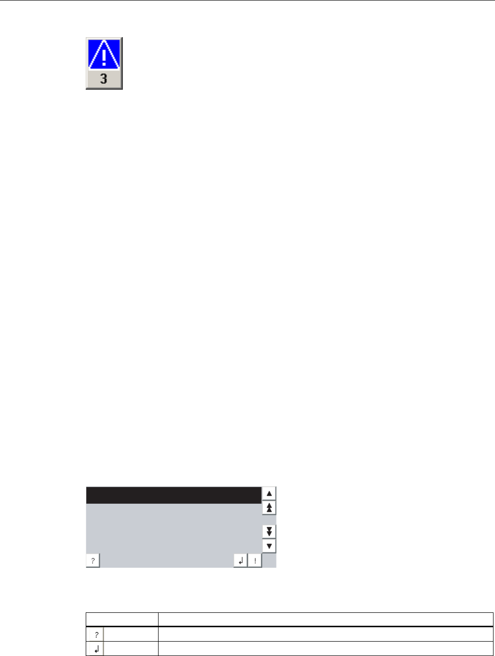
Operating alarms
10.3 Displaying alarms
Mobile Panel 277F IWLAN
Operating Instructions, 12/2007, A5E01003940-01 273
Figure 10-1 Alarm indicator with three pending alarms
The alarm indicator flashes as long as alarms are pending for acknowledgment. The number
displayed indicates the number of pending alarms. The configuration engineer can assign
functions to be executed when the alarm indicator is operated.
Usually, the alarm indicator is only used for error alarms. Please refer to your system
documentation to check whether additional information on this subject is available there.
10.3 Displaying alarms
Displaying alarms
Alarms are displayed in the alarm view or in the alarm window on the HMI device.
Alarm view
Depending on the configuration, the alarm view is displayed as follows:
● As a single line. Alarm numbers and alarm texts are displayed as single lines
● As simple alarm view
● As extended alarm view
In the simple or extended alarm views the configuration engineer specifies the alarm
information to be displayed.
Depending on the configuration, alarms from alarm logs are also displayed in the alarm view.
Simple alarm view
0RWRUWRRKRW
The buttons have the following functions:
Buttons Functions
Displaying infotext for an alarm.
Process alarm.
Operating alarms
10.3 Displaying alarms
Mobile Panel 277F IWLAN
274 Operating Instructions, 12/2007, A5E01003940-01
Buttons Functions
Acknowledge alarm.
Select the next or previous alarm in the list.
Scroll one page up or down.
Extended alarm view
0RWRUWRRKRW
.
'DWH7LPH1R 6WDWXV
The buttons have the following functions:
Buttons Functions
Displaying infotext for an alarm.
Process alarm.
Acknowledge alarm.
Changing the column sequence and sorting in the extended alarm view
Depending on the configuration, you can change the column sequence and sorting order on
HMI devices with touch operation.
● Change column sequence
– Touch the column header which you wish to exchange with a different column header
– Keeping the touch screen pressed, move the column heading to the column heading
you wish to exchange it with
● Change sorting order
To change the sorting order of the alarms, touch the respective column header on the
touch screen
Alarm class layout
The various alarm classes are identified in order to distinguish between them in the alarm
view.
Symbol Alarm class
! Error
Without a symbol Operation
Symbol depending on the configuration User-defined alarm classes
S7 SIMATIC or SIMOTION diagnostic alarms
Operating alarms
10.4 Display infotexts for an alarm
Mobile Panel 277F IWLAN
Operating Instructions, 12/2007, A5E01003940-01 275
Symbol Alarm class
$ System
The configuration engineer can change the symbols for the alarm classes. Please refer to
your system documentation to check whether additional information on this subject is
available there.
Alarm window
The alarm window is independent of the process screen. Depending on the configuration,
the alarm window opens automatically as soon as a new alarm is pending for
acknowledgment. The alarm window can be configured so that it only closes after all the
alarms have been acknowledged.
The layout and the operation of the alarm window are the same as for the alarm view.
Please refer to your system documentation to check whether additional information on this
subject is available there.
10.4 Display infotexts for an alarm
Displaying infotext
The configuration engineer can also provide infotext for alarms.
Procedure
Proceed as follows:
1. Touch the desired alarm in the alarm view or the alarm window.
The alarm is selected.
2. Touch the button in the simple alarm view or in the extended alarm view.
If configured, the infotext assigned to this alarm is displayed.
3. Close the screen for displaying the infotext by means of the button.
See also
Displaying alarms (Page 273)
10.5 Acknowledge alarm
Requirements
The alarm to be acknowledged is displayed in the alarm window or the alarm view.

Operating alarms
10.6 Edit alarm
Mobile Panel 277F IWLAN
276 Operating Instructions, 12/2007, A5E01003940-01
Procedure
Proceed as follows:
1. Touch the desired alarm in the alarm view or the alarm window.
The alarm is selected.
2. Touch the button in the simple alarm view or in the extended alarm view.
Alternative operation
Depending on the configuration, you can also acknowledge an alarm with a function key.
Result
The alarm is acknowledged. If the alarm belongs to an alarm group, all the alarms of the
associated group are acknowledged.
Please refer to your system documentation to check whether additional information on
acknowledgment and available alarm groups is available there.
10.6 Edit alarm
Introduction
The configuration engineer can assign additional functions to each alarm. These functions
are executed when the alarm is processed.
Note
When you edit an unacknowledged alarm, it is acknowledged automatically.
Requirements
The alarm to be edited is displayed in the alarm window or the alarm view.
Procedure
Proceed as follows:
1. Touch the desired alarm in the alarm view or the alarm window. The alarm is selected.
2. Touch the button in the simple alarm view or in the extended alarm view.
Result
The system executes the additional functions of the alarm. Please refer to your system
documentation to check whether additional information on this subject is available there.
Mobile Panel 277F IWLAN
Operating Instructions, 12/2007, A5E01003940-01 277
Operating recipes 11
11.1 Overview
Introduction
Recipes are used when different variants of a product are manufactured with the same
process. In this case, the product variants differ in terms of their type and quantity of the
components, but not in terms of the manufacturing process sequence. The configuration
engineer can store the combination of each individual product variant in a recipe.
Field of application
Recipes can be used everywhere the same product components are used in variable
combinations to create different product variants.
Examples:
● Beverage industry
● Food processing industry
● Pharmaceutical industry
● Paint industry
● Building materials industry
● Steel industry
11.2 Structure of a recipe
Recipes
The recipe collection for the production of a product family can be compared to a file cabinet.
A recipe which is used to manufacture a product corresponds to a drawer in a file cabinet.
Example:
In a plant for producing fruit juice, recipes are required for different flavors. There is a recipe,
for example, for the flavors orange, grape, apple and cherry.
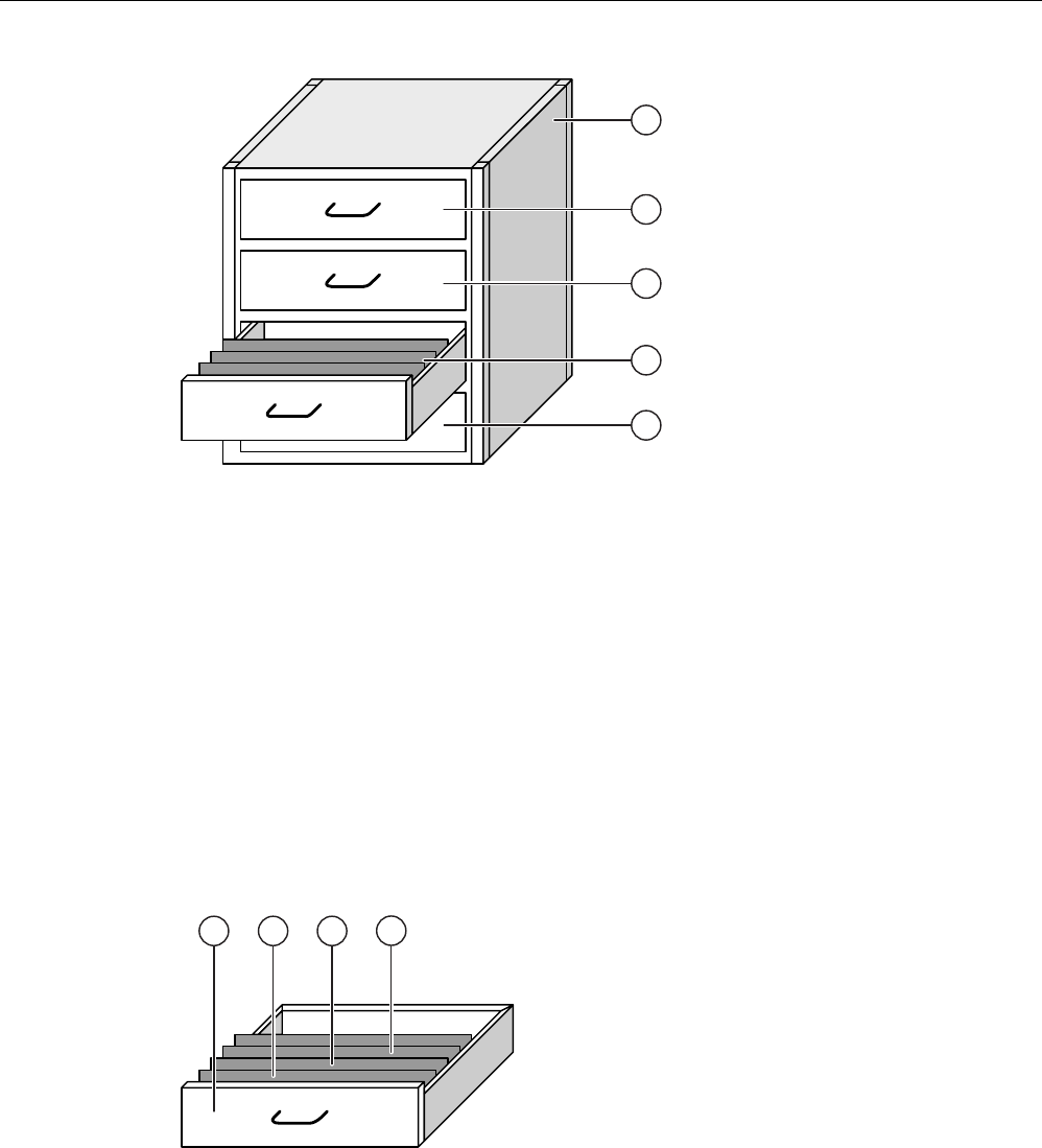
Operating recipes
11.2 Structure of a recipe
Mobile Panel 277F IWLAN
278 Operating Instructions, 12/2007, A5E01003940-01
① File cabinet Recipe collection Recipes for a fruit juice plant
② Drawer Recipe Orange flavored drinks
③ Drawer Recipe Grape flavored drinks
④ Drawer Recipe Apple flavored drinks
⑤ Drawer Recipe Cherry flavored drinks
Recipe data records
The drawers of the file cabinet are filled with suspension folders. The suspension folders in
the drawers represent records required for manufacturing various product variants.
Example:
Product variants of the flavor apple might be a soft drink, a juice or nectar, for example.
① Drawer Recipe Product variants of apple flavored drinks
② Suspension
folder
Recipe data
record
Apple drink
③ Suspension
folder
Recipe data
record
Apple nectar

Operating recipes
11.3 Recipes in the project
Mobile Panel 277F IWLAN
Operating Instructions, 12/2007, A5E01003940-01 279
④ Suspension
folder
Recipe data
record
Apple juice
Elements
In the figure showing the file cabinet, each suspension folder contains the same number of
sheets. Each sheet in the suspension folder corresponds to an element of the recipe data
record. All the records of a recipe contain the same elements. The records differ, however, in
the value of the individual elements.
Example:
All drinks contain the same components: water, concentrate, sugar and flavoring. The
records for soft drink, fruit juice or nectar differ, however, in the quantity of sugar used in
production.
11.3 Recipes in the project
Overview
If recipes are used in a project, the following components interact:
● Recipe view / recipe screen
On the HMI device, recipes are displayed and edited in the recipe view or in a recipe
screen.
– The recipe data records from the internal memory of the HMI device are displayed and
edited in the recipe view.
– The values of the recipe tags are displayed and edited in the recipe screen.
Depending on the configuration, the values displayed in the recipe view are synchronized
with the values of recipe tags.
● HMI device recipe memory
Recipes are saved in the form of data records in the HMI device recipe memory.
The recipe data can also be saved in recipe tags.
● Recipe tags
The recipe tags contain recipe data. When you edit recipes in a recipe screen, the recipe
values are stored in recipe tags. Depending on the configuration, the values of the recipe
tags are exchanged with the PLC.
The recipe tags can be synchronized with the recipe data records so that the same
values are saved in both.
● Memory card
The memory card is an external storage medium for recipe data records. The recipe data
records are exported from the HMI device recipe memory and are saved on the memory
card in a *.csv file. The records can be reimported from the memory card to the recipe
memory.
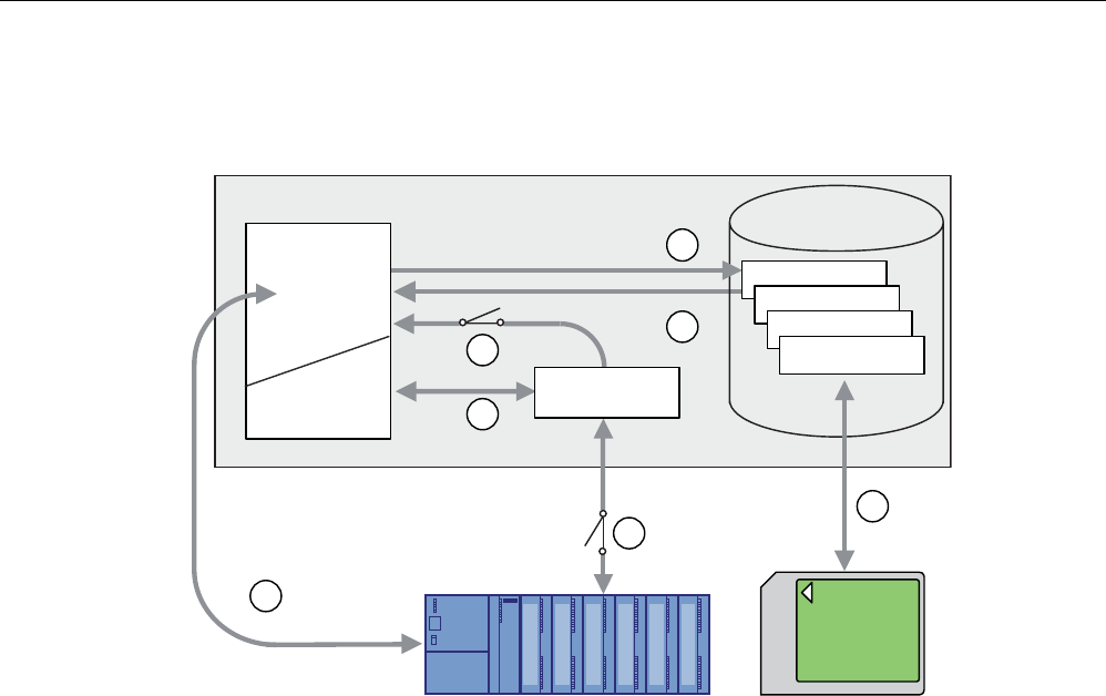
Operating recipes
11.4 Recipe displays
Mobile Panel 277F IWLAN
280 Operating Instructions, 12/2007, A5E01003940-01
Data flow
The following figure shows the data flow in a project with recipes.
5HFLSH
5HFLSH
5HFLSH
5HFLSHQ
5HFLSHPHPRU\
+0,GHYLFH
3/&
5HFLSHYLHZ
5HFLSH
VFUHHQ
5HFLSHWDJ
0HPRU\FDUG
① Editing, saving or deleting a recipe data record
② Display recipe data record
③ Synchronize or do not synchronize recipe tags
④ Display and edit recipe tags in the recipe screen
⑤ Write records from the recipe view to the PLC or read records from the PLC and
display them in the recipe view
⑥ Recipe tags are sent to the PLC online or offline
⑦ Export or import recipe data record to memory card
11.4 Recipe displays
Displaying recipes
You can display and edit recipes on the HMI device with a recipe view or recipe screen.
Recipe view
A recipe view is a screen object used to manage recipe data records. The recipe view shows
recipe data records in tabular form.
Depending on the configuration, the recipe view is displayed as follows:
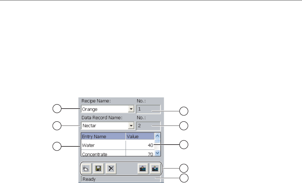
Operating recipes
11.4 Recipe displays
Mobile Panel 277F IWLAN
Operating Instructions, 12/2007, A5E01003940-01 281
● As extended recipe view
● As simple recipe view
The configuration engineer also defines which operator controls are displayed in the recipe
view.
Extended recipe view
The following figure shows an example of the extended recipe view.
① Selection box for the recipe
② Selection box for the recipe data record
③ Element name
The element name designates a specific element in the recipe data record
④ Display field
This show the number of the selected recipe or the selected recipe data record
⑤ Value of the element
⑥ Buttons for editing a recipe data record
⑦ Status bar for display of the status messages
Simple recipe view
The simple recipe view consists of three areas:
● Recipe list
● Data record list
● Element list
In the simple recipe view, each area is shown separately on the HMI device. Depending on
the configuration, the simple recipe view starts with the recipe list or data record list.
The following figure shows an example of the record list.
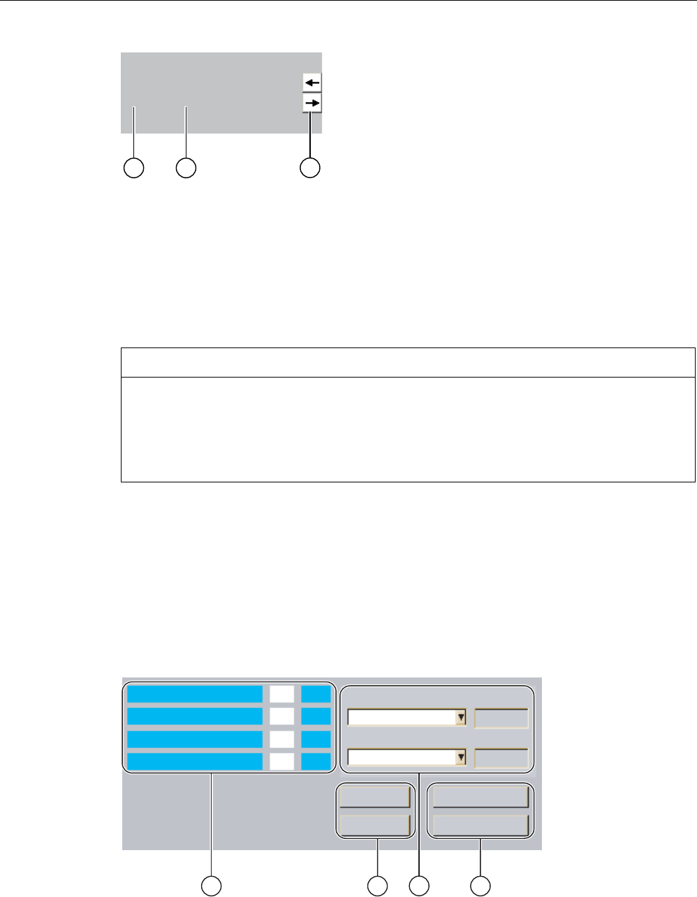
Operating recipes
11.4 Recipe displays
Mobile Panel 277F IWLAN
282 Operating Instructions, 12/2007, A5E01003940-01
%HYHUDJH
-XLFH
1HFWDU
① Number of the recipe data record
② Recipe data records
③ Buttons for changing the displayed list and calling the menu
Display of values
NOTICE
Changing the recipe data record in the background
Applies to the processing of a recipe data record:
If values of the corresponding recipe data record are changed by a PLC job, the recipe view
is not updated automatically.
To update the recipe view, reselect the respective recipe data record.
Recipe screen
A recipe screen allows the correlation between the plant and the recipe data to be displayed
in graphic form. The configuration engineer combines I/O fields and screen objects to form a
custom input screen. The configuration engineer can distribute the I/O fields of a recipe over
several recipe screens, thus allowing recipe elements to be arranged by subject. The recipe
screen can be operated using buttons configured accordingly.
The following figure shows an example of the recipe screen.
:DWHU
&RQFHQWUDWH
6XJDU
$URPD
5HFLSHQDPH
'DWDUHFRUGQDPH
1R
1R
6DYH
/RDG
'DWDIURPWKH3/&
'DWDWR3/&
2UDQJH
1HFWDU
O
O
NJ
O

Operating recipes
11.5 Recipe values in the HMI device and the PLC
Mobile Panel 277F IWLAN
Operating Instructions, 12/2007, A5E01003940-01 283
① Element name and associated values
The element name designates a specific element in the recipe data record
② Buttons for editing a recipe data record
③ Modified recipe view
④ Buttons for transferring recipe data
The values displayed or entered in the recipe screen are saved in recipe tags. The recipe
values are exchanged with the PLC immediately or later via these tags.
A configured recipe view can itself be a component of a recipe screen You must synchronize
the tags in order to synchronize data between the tags of the recipe screen and the recipe
data records displayed in the recipe view. Synchronization of tags is only possible in the
extended recipe view.
Please refer to your system documentation to check whether additional information on this
subject is available there.
11.5 Recipe values in the HMI device and the PLC
Introduction
You can change the values of a recipe on the HMI device and therefore influence the
manufacturing process or a machine.
Depending on the configuration, the recipe values are displayed, edited and saved in
different ways:
● If you are editing recipes with a recipe view in your project, the values are saved in recipe
data records
● If you are editing recipes in a recipe screen in your project, the values are saved in recipe
tags
Differences may occur between the display values in the recipe view and the values saved in
the associated tags in an ongoing project when you edit recipes with a recipe view and in a
recipe screen. To prevent this, the recipe data record values must be synchronized with the
values of the recipe tags.
You have however the option to perform synchronization operations at any time.
Synchronization only takes place if the configuration engineer has activated the respective
settings for a recipe.
Note
Recipe tags can only be synchronized in the extended recipe view.
Synchronizing recipe tags
Synchronization of the recipe tags depends on the configuration:
● Automatic synchronization:

Operating recipes
11.6 Operating the recipe view
Mobile Panel 277F IWLAN
284 Operating Instructions, 12/2007, A5E01003940-01
The values of the recipe view are synchronized with the associated recipe tags. In this
case, changes to values in the recipe view have an immediate effect on the values of the
associated recipe tags. The values are only synchronized, when an operating element
that is outside the recipe view is operated.
● Synchronization by the user:
The values of the recipe view and the associated recipe tags are not synchronized
automatically. The configuration engineer has assigned the same function to the
button or a different operating element in the recipe view. The recipe tags and the recipe
view are only synchronized when you operate the buttons or the appropriate operating
element.
Recipe tags online / offline
The configuration engineer can configure a recipe so that changes to the values of the recipe
tags do not have an immediate effect on the current process.
Synchronization of the recipe values between the HMI device and the PLC depends on
whether the configuration engineer has selected the settings "Tags online" or the setting
"Tags offline" for a recipe.
● "Tags online":
This setting has the following effect:
– When you change recipe values in the recipe screen, these changes are applied
immediately by the PLC and immediately influence the process
– If recipe values are changed in the PLC, the changed values are displayed
immediately in the recipe screen
● "Tags offline":
With this setting, changed recipe values are not synchronized immediately between the
HMI device and the PLC
In this case, the configuration engineer must configure operating elements for transferring
the values to the PLC or reading them from the PLC in a recipe screen. The recipe values
are only synchronized between HMI device and PLC when you operate the appropriate
operating element
11.6 Operating the recipe view
11.6.1 Overview
Operation
The recipe view can be operated as follows:
● Enter values for the recipe elements
● Create recipe data records
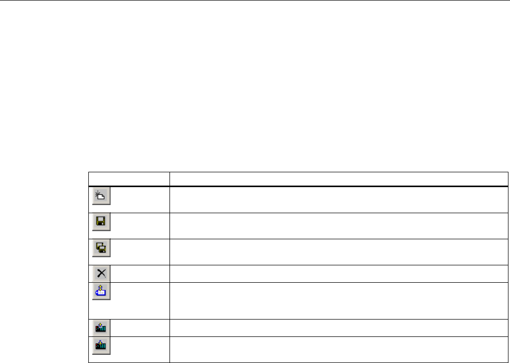
Operating recipes
11.6 Operating the recipe view
Mobile Panel 277F IWLAN
Operating Instructions, 12/2007, A5E01003940-01 285
● Save recipe data records or save them under a new name
● Delete recipe data records
● Synchronize values of the recipe view with the associated recipe tags
● Transfer recipe data records from the PLC and to the PLC
Operator controls of the recipe view
The following table shows the operator controls of the recipe view.
Buttons Functions
Creates a new recipe data record.
If a start value is configured, it is shown in the text box.
Saves the displayed values of the recipe data record.
The storage location is predefined by the project.
The recipe data record is saved under a different name irrespective of the recipe
view. A dialog box opens in which the name is entered.
The displayed recipe data record is deleted.
The values of the recipe view are synchronized with the associated recipe tags.
The values changed during editing are written to the associated recipe tags.
Subsequently all the values of the tags are read out and updated in the table.
The recipe values from the PLC are displayed in the recipe view.
The values of the set recipe data record displayed in the recipe view are
transferred to the PLC.
Operating the recipe screen
You operate the recipes in a recipe screen with the operator controls provided by the
configuration engineer.
Please refer to your system documentation to check whether additional information on this
subject is available there.
11.6.2 Creating a recipe data record
Introduction
You create a new recipe data record by modifying an existing record. You then save the
modified data record under a new name.
Requirements
A screen with a recipe view is displayed.

Operating recipes
11.6 Operating the recipe view
Mobile Panel 277F IWLAN
286 Operating Instructions, 12/2007, A5E01003940-01
Procedure
Proceed as follows:
1. If the recipe view contains several recipes: Select the recipe for which you want to create
a new recipe data record.
2. Touch .
A new recipe data record with the next available number is created.
If you change the new data record number to an existing data record number, the existing
data record is overwritten.
3. Enter values for the elements of the data record.
The elements of the recipe data record can be assigned default values depending on the
configuration.
4. Touch .
5. Enter a name for the data record.
The data record is saved under the new name.
If the recipe data record already exists, a dialog is opened. In this dialog, specify whether
the existing data record is to be overwritten.
Result
The new recipe data record is saved to the selected recipe.
See also
Recipes in the project (Page 279)
11.6.3 Editing a recipe data record
Introduction
Edit the values of the recipe data records and save them in a recipe view.
Synchronization with the PLC
If you want to display the current recipe values from the PLC in the recipe view, you first
have to read the current values from the PLC with .
The values changed in the recipe view only become effective when the amended data record
is transferred to the PLC by means of the button.
Requirements
A screen with a recipe view is displayed.

Operating recipes
11.6 Operating the recipe view
Mobile Panel 277F IWLAN
Operating Instructions, 12/2007, A5E01003940-01 287
Procedure
Proceed as follows:
1. If the recipe view contains several recipes: Select the recipe which contains the desired
recipe data record.
2. Select the recipe data record you want to change.
3. Change the data record as required.
4. Save your changes by means of the button.
If you want to save the recipe data record under a different name, touch the key.
5. The recipe data record is saved.
Result
The edited recipe data record has now been saved in the selected recipe.
See also
Recipes in the project (Page 279)
11.6.4 Deleting a recipe data record
Introduction
You can delete all the data records of a recipe which are not required.
Requirements
A screen with a recipe view is displayed.
Procedure
Proceed as follows:
1. If the recipe view contains several recipes: Select the recipe which contains the desired
recipe data record.
2. Select the recipe data record you want to delete.
3. Touch .
Result
The recipe data record is deleted.

Operating recipes
11.6 Operating the recipe view
Mobile Panel 277F IWLAN
288 Operating Instructions, 12/2007, A5E01003940-01
See also
Recipes in the project (Page 279)
11.6.5 Synchronizing tags
Introduction
The values of the recipe elements can be saved to recipe tags, depending on the
configuration.
Differences may occur between the display values in the recipe view and the actual values of
tags in an ongoing project. Synchronize the tags to equalize such differences.
Synchronization always includes all the variables which belong to a recipe data record.
NOTICE
Changed tag name
Tags and the value of the recipe data record cannot be assigned to each other if the tag
name of the tag to be synchronized has been changed. The tags in question are not
synchronized.
Note
Recipe tags can only be synchronized in the enhanced recipe view.
Requirement
A screen with a recipe view is displayed.
Procedure
Proceed as follows:
1. If the recipe view contains several recipes: Select the recipe which contains the desired
recipe data record.
2. Select the recipe data record you want to synchronize.
3. Touch .
Result
The elements of the recipe data record are synchronized with the recipe tags.
If the values of the recipe view and the tag do not match, the more current value is accepted.

Operating recipes
11.6 Operating the recipe view
Mobile Panel 277F IWLAN
Operating Instructions, 12/2007, A5E01003940-01 289
See also
Recipes in the project (Page 279)
11.6.6 Reading a recipe data record from the PLC
Introduction
In the current project, the values which are also stored in the recipes in the HMI device can
be changed directly in the plant. This is the case, for example, if a valve was opened further
directly at the plant than is stored in the recipe. The values of the recipe data records saved
in the HMI device possibly no longer match the values in the PLC.
To synchronize the recipe values, read the values from the PLC and display them in the
recipe view.
Requirements
A screen with a recipe view is displayed.
Procedure
Proceed as follows:
1. If the recipe view contains several recipes: Select the recipe which contains the desired
recipe data record.
2. Select the recipe data record to which you want to apply the values from the PLC.
3. Touch .
The values are read from the PLC.
4. If you want to store the displayed values in the HMI device, touch the button.
Result
The values were read from the PLC, displayed on the HMI device and saved to the selected
recipe data record.
See also
Recipes in the project (Page 279)

Operating recipes
11.7 Operating the simple recipe view
Mobile Panel 277F IWLAN
290 Operating Instructions, 12/2007, A5E01003940-01
11.6.7 Transferring a recipe data record to the PLC
Introduction
In order for an edited recipe data record to take effect in the process, you must transfer the
values to the PLC.
The display values in the recipe view are always transferred to the PLC.
Requirements
A screen with a recipe view is displayed.
Procedure
Proceed as follows:
1. If the recipe view contains several recipes: Select the recipe which contains the desired
recipe data record.
2. Select the recipe data record whose values you want to transfer to the PLC.
3. Touch .
Result
The display values in the recipe view were transferred to the PLC and take effect in the
process.
See also
Recipes in the project (Page 279)
11.7 Operating the simple recipe view
11.7.1 Overview
Introduction
The simple recipe view consists of three areas:
● Recipe list
● Data record list
● Element list
You can use the context menu to operate each of these display areas.
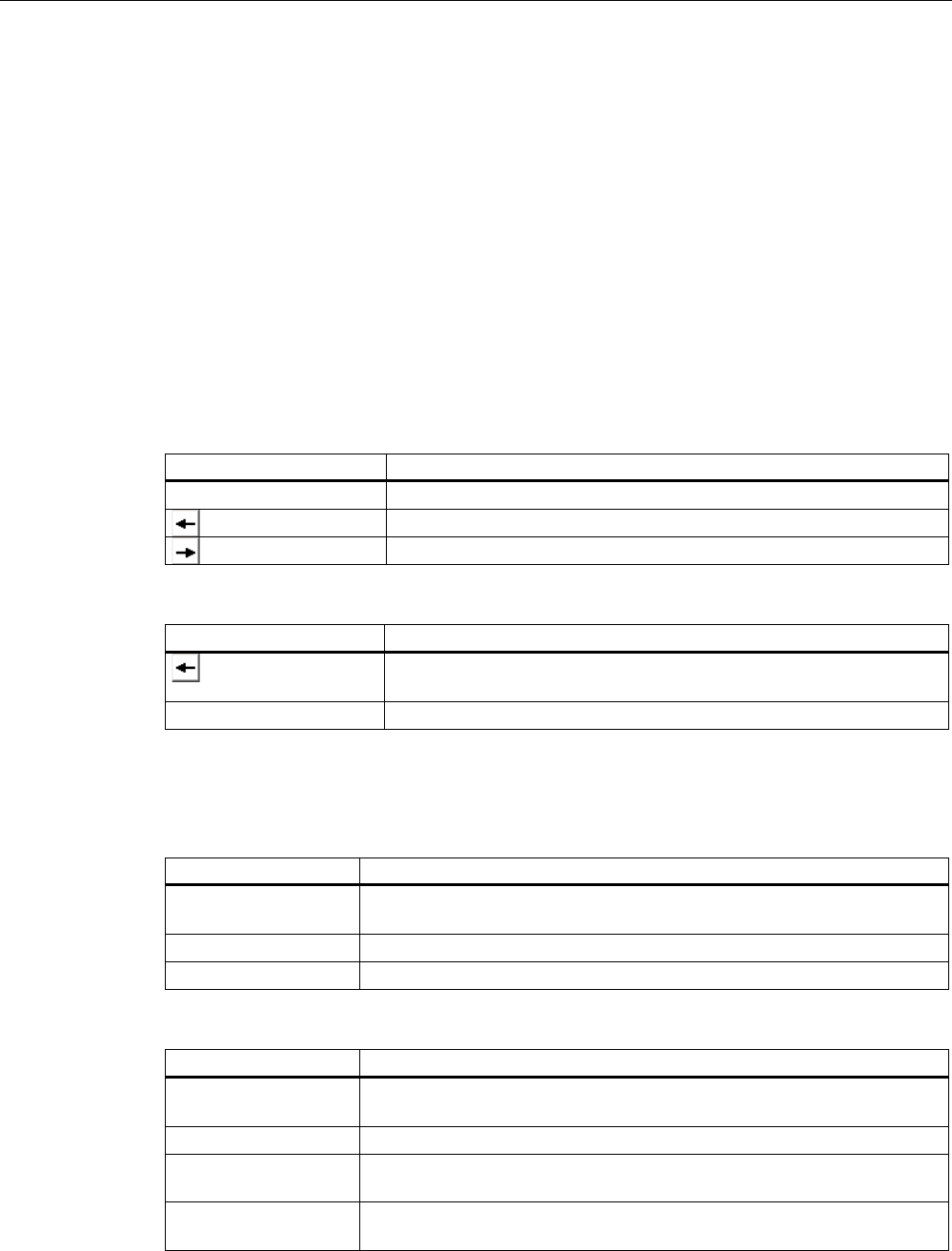
Operating recipes
11.7 Operating the simple recipe view
Mobile Panel 277F IWLAN
Operating Instructions, 12/2007, A5E01003940-01 291
Operation
The simple recipe view can be operated as follows:
● Enter values for the recipe elements
● Create recipe data records
● Save recipe data records or save them under a new name
● Delete recipe data records
● Transfer recipe data records from the PLC and to the PLC
Operator controls of the simple recipe view
Toggle between the display areas and the context menus to operate the simple recipe views.
The following table shows the operation of the display area.
Operation Functions
Touching an entry The next lower display area opens.
The next higher display area opens.
The context menu of the display area opens.
The following table shows the operation of the context menu.
Operation Functions
The menu is closed.
The display area opens.
Touch the menu command The menu command is executed.
Context menus of the simple recipe view
● Recipe list
Menu item Functions
New A new recipe data record is created for the selected recipe.
If a start value is configured, it is shown in the text box.
Displaying infotext The infotext configured for the simple recipe view is displayed.
Open The record list of the selected recipe opens.
● Data record list
Menu item Functions
New A new recipe data record is created for the selected recipe.
If a start value is configured, it is shown in the text box.
Delete The selected record is deleted.
Save as The selected record is saved under a different name irrespective of the
simple recipe view. A dialog box opens in which the name is entered.
Rename The selected data record is renamed. A dialog box opens in which the
name is entered.

Operating recipes
11.7 Operating the simple recipe view
Mobile Panel 277F IWLAN
292 Operating Instructions, 12/2007, A5E01003940-01
● Element list
Menu item Functions
Save The selected record is saved.
To PLC The displayed values of the selected data record are transferred from the
HMI device to the PLC.
From PLC The recipe values from the PLC are displayed on the HMI device in the
recipe view.
Save as The selected data record is saved under a new name. A dialog box opens
in which the name is entered.
Operating the menu
Touch the desired menu command. The command is executed.
Operating the recipe screen
You operate the recipes in a recipe screen with the operator controls provided by the
configuration engineer.
Please refer to your system documentation to check whether additional information on this
subject is available there.
11.7.2 Creating a recipe data record
Introduction
Create a new recipe data record in the recipe list or in the record list. Then enter the values
for the new record in the element list and save the record.
Requirements
A screen with a simple recipe view is displayed.
Procedure
Proceed as follows:
1. If the recipe list contains several recipes: Select the recipe for which you want to create a
new recipe data record.
2. Open the recipe list menu.
3. Select the menu command "New".
Creates a new record
The element list of the new record opens.
4. Enter values for the elements of the data record.

Operating recipes
11.7 Operating the simple recipe view
Mobile Panel 277F IWLAN
Operating Instructions, 12/2007, A5E01003940-01 293
The tags of the record can be assigned default values depending on the configuration.
5. Open the menu of the element list and select the command "Save".
6. Enter a name for the new record.
7. Confirm your entries.
If you change the new data record number to an existing data record number, the existing
data record is overwritten.
Result
The new recipe data record is saved to the selected recipe.
See also
Recipes in the project (Page 279)
11.7.3 Editing a recipe data record
Introduction
Edit the values of the recipe data records in a simple recipe view.
Synchronization with the PLC
If you want to display the current recipe values from the PLC in the simple recipe view, you
first have to read the current values from the PLC with the menu command "From PLC" in
the element list.
The values changed in the recipe view only take effect in the PLC when you transfer the
edited data record to the PLC with the menu command "To PLC".
Requirements
A screen with a simple recipe view is displayed.
Procedure
Proceed as follows:
1. If the recipe list contains several recipes: Select the recipe which contains the desired
recipe data record.
2. Open the data record list.
3. Select the recipe data record you want to change.
4. Open the element list.
5. Change the values of the records as required.
6. Save your changes with the menu command "Save".

Operating recipes
11.7 Operating the simple recipe view
Mobile Panel 277F IWLAN
294 Operating Instructions, 12/2007, A5E01003940-01
The recipe data record is saved.
Result
The edited recipe data record has now been saved in the selected recipe.
See also
Recipes in the project (Page 279)
11.7.4 Deleting a recipe data record
Introduction
You can delete all the data records which are not required.
Requirements
A screen with a simple recipe view is displayed.
Procedure
Proceed as follows:
1. If the recipe list contains several recipes: Select the recipe which contains the desired
recipe data record.
2. Open the data record list.
3. Select the data record you want to delete.
4. Open the menu.
5. Select the menu command "Delete".
Result
The data record is deleted.
See also
Recipes in the project (Page 279)

Operating recipes
11.7 Operating the simple recipe view
Mobile Panel 277F IWLAN
Operating Instructions, 12/2007, A5E01003940-01 295
11.7.5 Reading a recipe data record from the PLC
Introduction
The values of recipe elements are exchanged with the PLC via tags.
In the current project, the values which are also stored in the recipes in the HMI device can
be changed directly in the plant. This is the case, for example, if a valve was opened further
directly at the plant than is stored in the recipe. The values of the tags on the HMI device
possibly no longer match the values in the PLC.
To synchronize the recipe values, read the values from the PLC and display them in the
recipe view.
Requirements
A screen with a simple recipe view is displayed.
Procedure
Proceed as follows:
1. If the recipe list contains several recipes: Select the recipe which contains the desired
recipe data record.
2. Select the element list of the recipe data record to which you want to apply the values
from the PLC.
3. Open the menu.
4. Select the menu item "From PLC".
The values are read from the PLC.
5. If you want to save the displayed values in the HMI device, select the menu item "Save".
Result
The values were read from the PLC, displayed on the HMI device and saved to the selected
recipe data record.
See also
Recipes in the project (Page 279)
11.7.6 Transferring a recipe data record to the PLC
Introduction
In order for an edited recipe data record to take effect in the process, you must transfer the
values to the PLC.

Operating recipes
11.8 Exporting a recipe data record
Mobile Panel 277F IWLAN
296 Operating Instructions, 12/2007, A5E01003940-01
The display values in the recipe view are always transferred to the PLC.
Requirements
A screen with a simple recipe view is displayed.
Procedure
Proceed as follows:
1. If the recipe list contains several recipes: Select the recipe which contains the desired
recipe data record.
2. Select the element list of the recipe data record whose values you want to transfer to the
PLC.
3. Open the menu.
4. Select the menu item "To PLC".
Result
The values of the recipe data record were transferred to the PLC and take effect in the
process.
See also
Recipes in the project (Page 279)
11.8 Exporting a recipe data record
Introduction
You can export one or more recipe data records to a CSV file, depending on the
configuration. After export, the values in the recipe data record can be further processed in a
spreadsheet program such as MS Excel. The degree to which you can influence the export
depends on the configuration:
NOTICE
Export of recipe data to USB memory stick not possible
The USB interface is deactivated while the main battery is changed. Make sure that no
recipe data is exported to a USB memory stick while the main battery is being changed.
Requirements
● A screen with a recipe view is displayed
● An operating element with the function "Export record" has been configured.

Operating recipes
11.9 Importing a recipe data record
Mobile Panel 277F IWLAN
Operating Instructions, 12/2007, A5E01003940-01 297
● The following tags are configured equally in the recipe view and for the "Export record"
operating element.
– Recipe number
– Data record number
Procedure
Proceed as follows:
1. If the recipe view contains several recipes: Select the recipe which contains the desired
recipe data record.
2. Select the recipe data record you want to export.
3. Operate the operator control which was configured for export, for example the "Export
data record" button.
The data record is exported as a CSV file to an external data medium.
Please refer to your system documentation to check whether additional information on this
subject is available there.
Result
The recipe data record is exported.
11.9 Importing a recipe data record
Introduction
You can import values from a CSV file to a recipe data record, depending on the
configuration.
Requirements
● An operating element with the function "Import data record" has been configured, for
example a button
● A screen with a recipe view is displayed
Procedure
Proceed as follows:
1. If the recipe view contains several recipes: Select the recipe which contains the recipe
data record to be imported.
2. Operate the operating element with the function "Import data record".
The record is imported from an external data medium as a CSV file and then displayed in
the recipe view after import.

Operating recipes
11.10 Examples
Mobile Panel 277F IWLAN
298 Operating Instructions, 12/2007, A5E01003940-01
Result
The imported recipe data record is saved on the HMI device.
Deviating structure
If the structure of the CSV file differs from the structure of the recipe, deviations are handled
as follows:
● Any additional values in the CSV file will be rejected
● The system applies the configured default value to the recipe data record if the CSV file
contains an insufficient number of values
● If the CSV file contains values of the wrong data type, the configured default value is set
in the recipe data record
Example:
The imported CSV file contains values that were entered as floating point numbers
However, the corresponding tag expects an integer value. In this case, the system
discards the imported value and uses the configured default
11.10 Examples
11.10.1 Entering a recipe data record
Introduction
You would like to enter production data on the HMI device without interrupting the process in
the machine or plant. For this reason, the production data should not be transferred to the
PLC.
Procedure
Proceed as follows:
1. Call the recipe view or a recipe screen.
2. Select the desired recipe data record.
3. Enter the values of the elements.
4. Save the recipe data record.
The recipe data record is saved in the internal memory of the HMI device.
The following figure shows the data flow schematically.
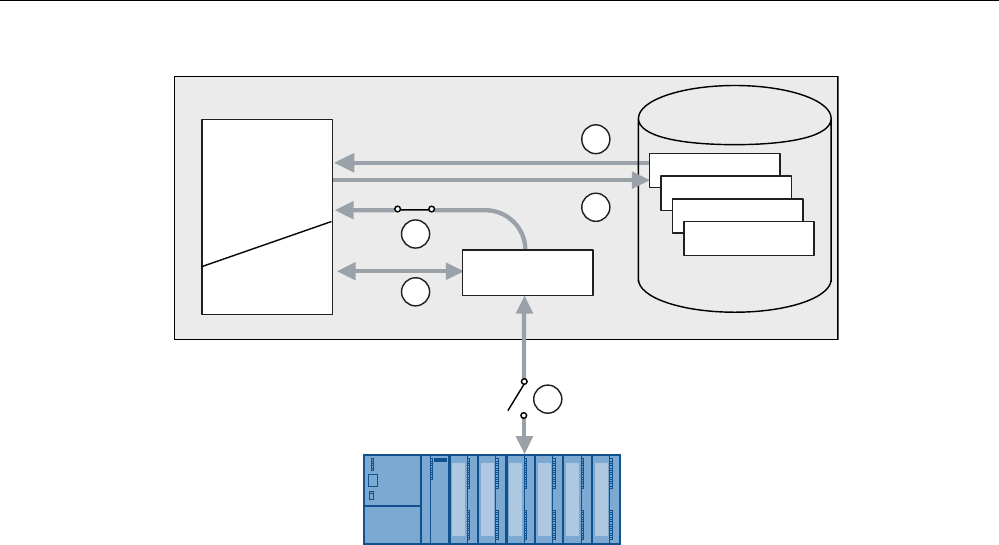
Operating recipes
11.10 Examples
Mobile Panel 277F IWLAN
Operating Instructions, 12/2007, A5E01003940-01 299
5HFLSH
5HFLSH
5HFLSH
5HFLSHQ
5HFLSHPHPRU\
+0,GHYLFH
3/&
5HFLSHYLHZ
5HFLSH
VFUHHQ
5HFLSHWDJ
① Display recipe data record
② Save recipe data record
③ Tags are synchronized
④ Display and edit recipe tags in the recipe screen
⑤ Tags are offline
11.10.2 Manual production sequence
Introduction
You request the production data of different workpieces from the PLC and display this data
on the screen of the HMI device for inspection. You want to correct the transferred
production data in the recipe view or the recipe screen if necessary.
Procedure
A scanner connected to the PLC reads the barcode of a workpiece. The barcode names
correspond to the names in the recipe data record. Based on the barcode name, the PLC
can read the required recipe data record. The recipe data record is displayed for inspection
on the HMI device. You can now edit and save the recipe data record. Then transfer the
edited recipe data record to the PLC again.
The following figure shows the data flow schematically.
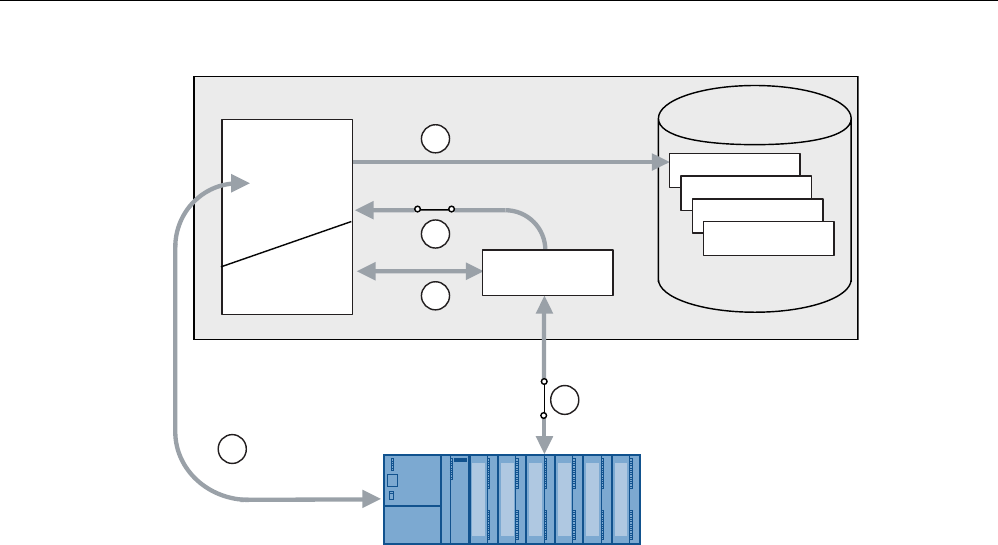
Operating recipes
11.10 Examples
Mobile Panel 277F IWLAN
300 Operating Instructions, 12/2007, A5E01003940-01
5HFLSH
5HFLSH
5HFLSH
5HFLSHQ
5HFLSHPHPRU\
+0,GHYLFH
3/&
5HFLSHYLHZ
5HFLSH
VFUHHQ
5HFLSHWDJ
① The recipe data record is read from the PLC and written to the PLC again following
changes
② Display and edit recipe tags in the recipe screen
③ Tags are synchronized
④ Recipe data records are saved in the recipe memory of the HMI device

Mobile Panel 277F IWLAN
Operating Instructions, 12/2007, A5E01003940-01 301
Maintenance and care 12
12.1 Maintenance and care
Scope of maintenance
● Function tests
Carry out the specified tests in the periods of time prescribed for each. Otherwise, the
functionality of the HMI device is not guaranteed.
To perform the function tests, the HMI device must be switched on but not integrated.
– Press the emergency stop button at least once a year.
– Press both enabling buttons every time you start a project.
● HMI device
The HMI device is designed for maintenance-free operation. The touch screen and
keyboard overlay should nevertheless be cleaned regularly.
● Maintenance cycle of battery
We recommend that you replace the battery when it can only be charged to 50%. This is
the case after approximately 500 complete charging cycles.
A charging cycle is complete when the battery is fully charged.
Example:
The battery has a charging condition of 80%. It needs another 20% before it is fully
charged. The battery is charged. This charging process counts as one fifth of a complete
charging cycle.
● Transponder batteries
Replace the transponder batteries at least every 5 years.
Cleaning the HMI device
CAUTION
Inadvertent operation
Always switch off the HMI device before cleaning it. This will ensure that you do not trigger
unintended functions when you touch the keys.

Maintenance and care
12.2 Spare parts and repairs
Mobile Panel 277F IWLAN
302 Operating Instructions, 12/2007, A5E01003940-01
CAUTION
Do not clean the HMI device with compressed air or steam jet blowers. Never use
aggressive solvents or scouring powder.
Use a cleaning cloth dampened with a cleaning agent to clean the equipment. Only use
water with a little liquid soap or a screen cleaning foam.
Procedure
Proceed as follows:
1. Switch off the HMI device.
2. Spray the cleaning solution onto a cleaning cloth.
Do not spray directly onto the HMI device.
3. Clean the HMI device.
When cleaning the display wipe from the screen edge inwards.
12.2 Spare parts and repairs
Repairs
In case of repair, the HMI device must be shipped to the Return Center in Fürth. Repairs
may only be carried out at the Return Center in Fürth.
Depending on the work necessary to repair the device, the Center may decide to give you a
credit note. In this case, it is your responsibility to order a new device.
The address is:
A&D Return Center
Siemensstr. 2
90766 Fürth, Germany
Service pack
A service pack can be ordered for servicing purposes.
The service pack includes:
● For the HMI device
– Cover caps
– Battery compartment cover
– Bridging battery
● For the charging station
– Covers for the battery compartment in the charging station.

Maintenance and care
12.2 Spare parts and repairs
Mobile Panel 277F IWLAN
Operating Instructions, 12/2007, A5E01003940-01 303
– Lock
– Key set for lock
– Counterpart for power supply connector
The service pack can be ordered from your Siemens representative.
Replacement key set
You can order a replacement key set for the HMI device from your Siemens sales office.
Replacement batteries
Main batteries and bridge batteries can be ordered from your Siemens sales office.
Service & Support on the Internet
Service & Support provides additional comprehensive information on SIMATIC products
through online services at "http://www.siemens.com/automation/support".
Information about on-site services, repairs, spare parts, and much more is available on our
"Services" pages.
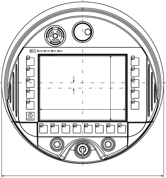
Mobile Panel 277F IWLAN
Operating Instructions, 12/2007, A5E01003940-01 305
Technical specifications 13
13.1 Dimension drawings
13.1.1 Mobile Panel 277F IWLAN
Front view
$OOGLPHQVLRQVLQPP
º
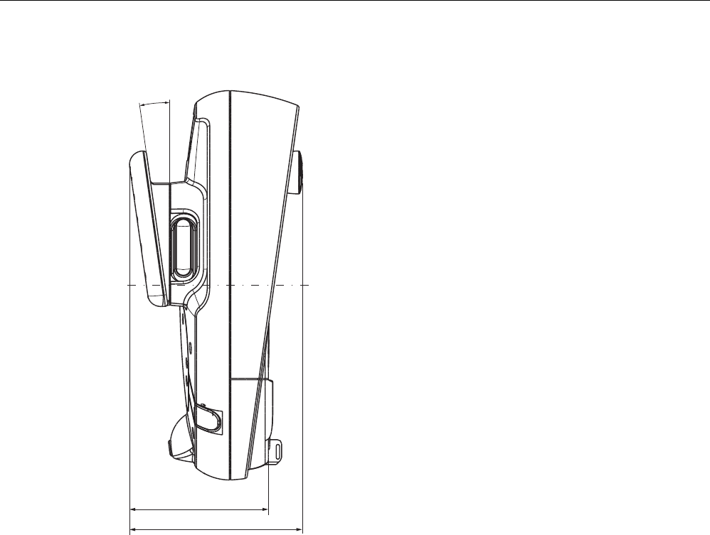
Technical specifications
13.1 Dimension drawings
Mobile Panel 277F IWLAN
306 Operating Instructions, 12/2007, A5E01003940-01
Side view
$OOVSHFLILFDWLRQVLQPP
r
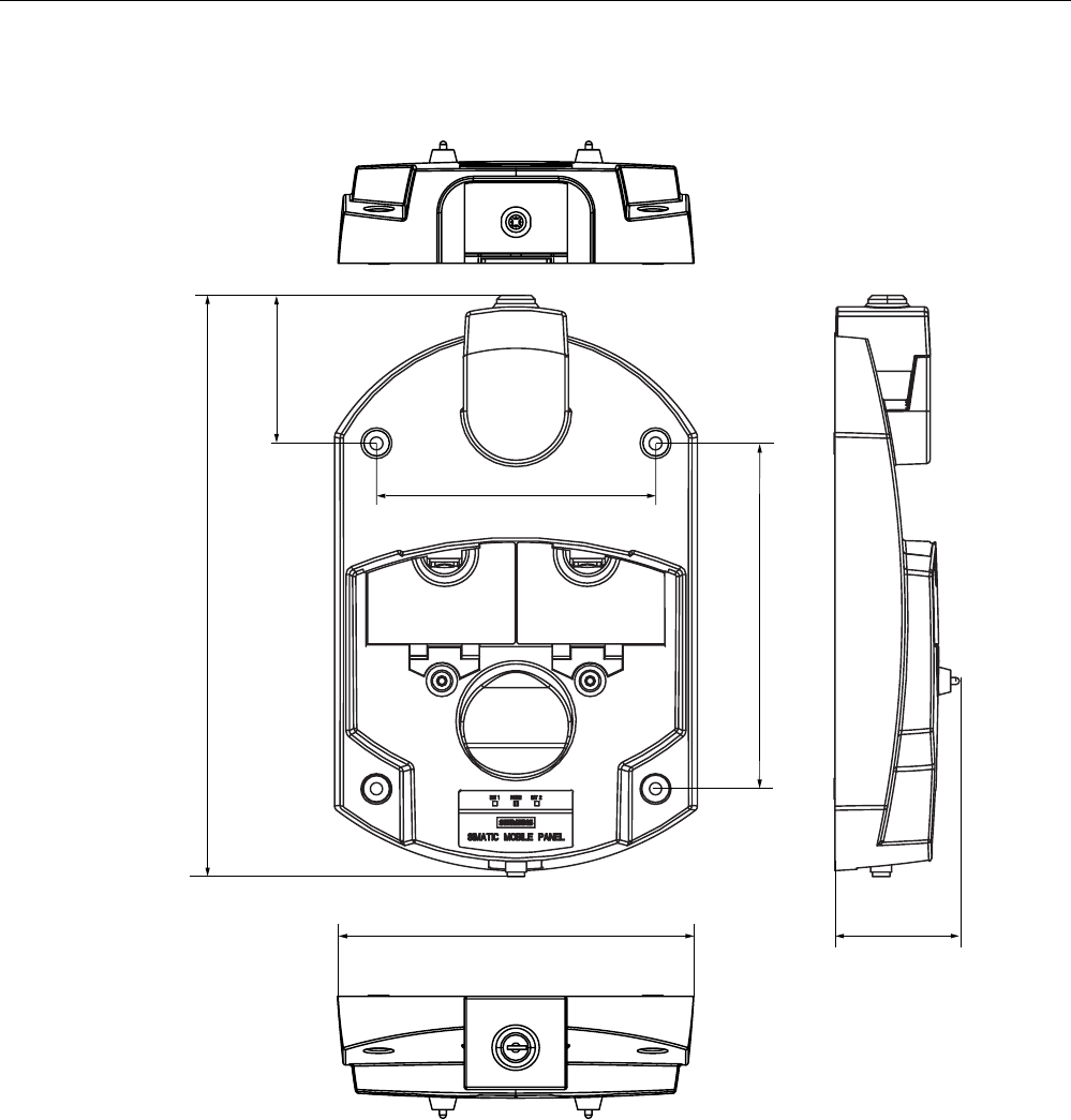
Technical specifications
13.1 Dimension drawings
Mobile Panel 277F IWLAN
Operating Instructions, 12/2007, A5E01003940-01 307
13.1.2 Charging station
$OOGLPHQVLRQVLQPP
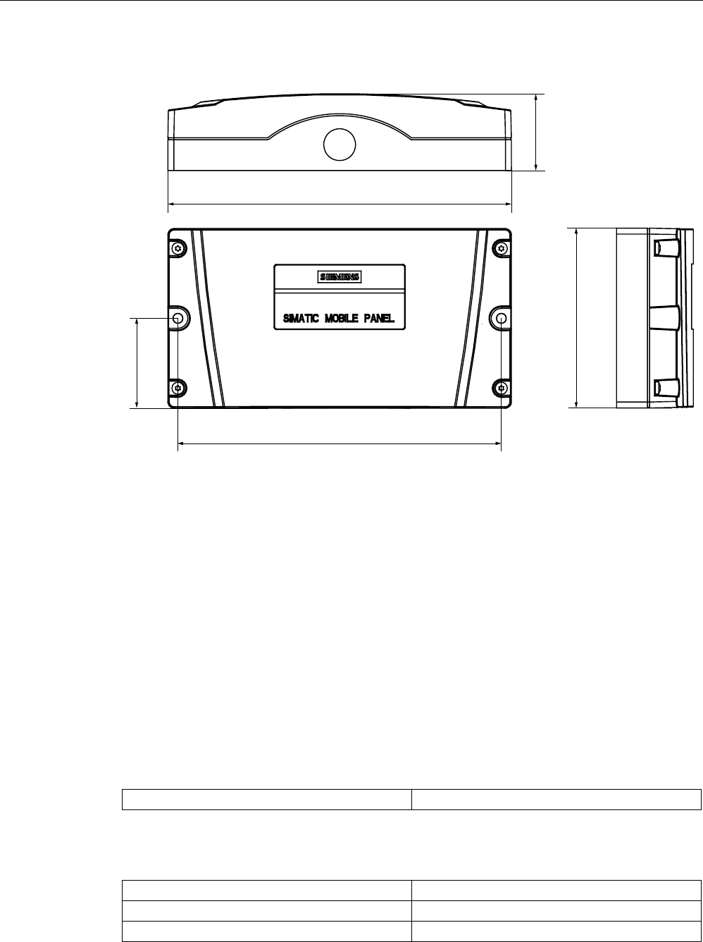
Technical specifications
13.2 Specifications
Mobile Panel 277F IWLAN
308 Operating Instructions, 12/2007, A5E01003940-01
13.1.3 Transponder
$OOGLPHQVLRQVLQPP
13.2 Specifications
13.2.1 Mobile Panel 277F IWLAN
HMI device
Weight with battery and without packaging Max. 2.2 kg
Display
Type Color TFT LC display
Display area, active 151.66 mm x 113.74 mm (7.5")
Resolution 640 x 480 pixels
Technical specifications
13.2 Specifications
Mobile Panel 277F IWLAN
Operating Instructions, 12/2007, A5E01003940-01 309
Colors, displayable 64k colors
Brightness control Yes
Back-lighting
Half Brightness Life Time, typical
CCFL
50,000 h
Pixel error class according to DIN EN ISO 13406-
2
II
Input unit
Type Touch screen, analog, resistive
Membrane keyboard
Function keys 18, with LEDs
Enabling button 1
Emergency off button (optional) 1
ON/OFF button 1
Handwheel (optional) 1
50 pulses per rotation
Key-operated switch (optional) 1
3 switch settings
Illuminated pushbutton (optional) 2
LED separately controllable
Memory
Application memory 6 MB
Ports
1 x USB • USB host; conforms to USB standard 1.1
(supporting low-speed and full-speed USB
devices)
• Maximum load 100 mA
1 x WLAN For PROFINET WLAN
1 x RS 45 For PROFINET LAN
Supply voltage
Supply voltage
About • Battery
• Charging station
• Tabletop power supply unit
Technical specifications
13.2 Specifications
Mobile Panel 277F IWLAN
310 Operating Instructions, 12/2007, A5E01003940-01
Additional specifications
Drop height with main battery Max. 1.2 m
Buffer time of internal clock with bridging battery
inserted
Approx. 4 days
Radio link to transponder
• Frequency band
• Transmission angle
• 2400 - 2483 MHz
• Approx. 83 °
Fail-safe mode
WARNING
The safety characteristics in the specifications apply for a proof-test interval of 10 years and
a mean repair time of 8 hours.
In accordance with IEC 61508
Hardware architecture Redundant 1oo2d
Hardware error tolerance 1
Safe failure fraction 99,5 %
Diagnostic test interval 10 years
Request rate High demand mode
High demand (PFH: probability of a dangerous failure
per hour)
8,12E-11 1/h
Maximum achievable safety class (SIL) 3
Useful life 10 years
In accordance with DIN EN ISO 13849-1
Mean time to failure (MTTFd) 1679 years
Meantime to Restoration (MTTR) 8 hours
Diagnostic coverage (DC) 99 %
Performance level (PL) e
Safety category 4
In accordance with EN 954-1
Safety category 4
Other safety-related values
Reaction time ??
Discrepancy time
• Emergency stop
• Enabling button position "Enable"
• Enabling button position "Panic"
• 500 ms
• 2 sec
• 1 sec
Technical specifications
13.2 Specifications
Mobile Panel 277F IWLAN
Operating Instructions, 12/2007, A5E01003940-01 311
Quantity structure for the effective range concept
F-FBs required in safety program
F_FB_MP 1x per Mobile Panel 277F IWLAN, maximum 126
F_FB_RNG_4 1x per effective range, for which up to 4 HMI devices have logging on
authorization
F_FB_RNG_16 1x per effective range, for which up to 16 HMI devices have logging on
authorization
DB_STATES 1
Configuring
Maximum number of transponders used in the
project for effective ranges
127
Maximum number of effective ranges in the
project
127
Maximum number of transponders per effective
range
127
Maximum number of HMI devices with logging on
authorization per effective range
• When using F_FB_RNG_4: 4 HMI devices
• When using F_FB_RNG_16: 16 HMI devices
Maximum configurable distance between
transponder and HMI device
8 m
13.2.2 Batteries
Main battery
Type Lithium ion accumulator
Operation time in normal mode Approx. 4 h
Operation time in stand-by mode Approx. 15 days
Charging cycles 500
Charging time Approx. 4 h 1)
Bridging battery
Type Lithium ion accumulator
Bridging time 5 min
Charging cycles 500
1) The effective charging time depends on the ambient temperature.
The higher the ambient temperature, the longer the charging time.

Technical specifications
13.2 Specifications
Mobile Panel 277F IWLAN
312 Operating Instructions, 12/2007, A5E01003940-01
13.2.3 Charging station
Weight
Weight without packing Approx. 1.1 kg
Supply voltage
Nominal voltage
Range, permissible
+24 VDC
19.2 V to 28.8 V (–20%, +20%)
Transients, maximum permissible 35 V (500 ms)
Time between two transients, minimum 50 sec
Current consumption with Mobile Panel
• Typical
• Constant current, maximum
• Power on current surge I2t
• Approx. 1.5 A
• Approx. 1.8 A
• Approx. 1.7 A2s
Current consumption with Mobile Panel and batteries in
charging compartment
• Typical
• Constant current, maximum
• Power on current surge I2t
• Approx. 2.8 A
• Approx. 3.4 A
• Approx. 1.7 A2s
Fuse, internal Electronic
13.2.4 Transponder
Weight without batteries 0,3 kg
Power supply 3 AA mignon batteries, 1.5 V
Operating life of batteries in normal operation 5 years
Radio link to HMI device
• Frequency band
• Transmission angle
• 2400 - 2483 MHz
• Approx. 93°
Type Passive

Technical specifications
13.2 Specifications
Mobile Panel 277F IWLAN
Operating Instructions, 12/2007, A5E01003940-01 313
13.2.5 Description of interfaces on the HMI device
USB
The figure below shows the pin assignment of the USB interface.
Pin Assignment
1 +5 VDC, out (max. 100 mA)
2 USB-DN
3 USB-DP
4 GND
RJ45
The figure below shows the pin assignment of the RJ45 interface.
Pin Assignment
1 TD+
2 TD–
3 RD+
4 n. c.
5 n. c.
6 RD–
7 ICD+
8 ICD–
WLAN
WLAN in accordance with IEEE 802.11 a
See also
Interfaces of the HMI device (Page 76)
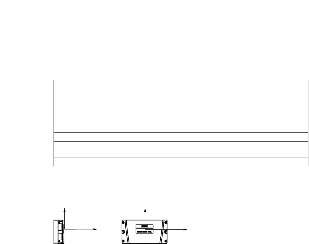
Technical specifications
13.3 Radiation characteristic
Mobile Panel 277F IWLAN
314 Operating Instructions, 12/2007, A5E01003940-01
13.3 Radiation characteristic
13.3.1 Radiation characteristic of the transponder
Antenna type Dual port patch antenna
Polarization Vertical and horizontal
Frequency band 2400 - 2483 MHz
Antenna gain Max. in main count direction
• Port 1: 2,6 dBic
• Port 2: 2.7 dBic
Impedance 50 Ω
Full widths at half maximum, horizontal at
2.45 GHz
93°
Full widths at half maximum, vertical at 2.45 GHz 90°
Ranges depending on angular displacement to main count direction
The following figure shows the coordinate system applied to the transponder.
[
]
\
]
The figure below shows the transponder range depending on the angular displacement to
the main count direction in the y direction:

Technical specifications
13.3 Radiation characteristic
Mobile Panel 277F IWLAN
Operating Instructions, 12/2007, A5E01003940-01 315
x
1 m
2 m
3 m
4 m
5 m
6 m
7 m
8 m
y
15
°
30
°
45
°
60
°
75
°
-15
°
-30
°
-45
°
-60
°
-75
°
105
°
120
°
135
°
150
°
165
°
180
°
-165
°
-150
°
-135
°
-120
°
-105
°
-90
°
x
The following figure shows the transponder range depending on the angular displacement to
the main count direction in the z direction:
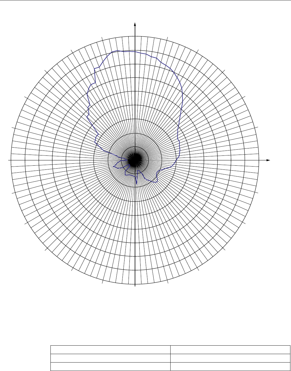
Technical specifications
13.3 Radiation characteristic
Mobile Panel 277F IWLAN
316 Operating Instructions, 12/2007, A5E01003940-01
1 m
2 m
3 m
4 m
5 m
6 m
7 m
8 m
z
15
°
30
°
45
°
60
°
75
°
-15
°
-30
°
-45
°
-60
°
-75
°
105
°
120
°
135
°
150
°
165
°
180
°
-165
°
-150
°
-135
°
-120
°
-105
°
-90
°
x
13.3.2 Radiation characteristic of HMI device
Antenna type Dual port patch antenna
Polarization Vertical and horizontal
Frequency band 2400 - 2483 MHz
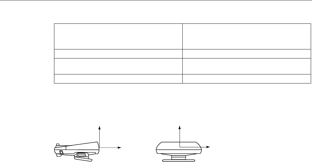
Technical specifications
13.3 Radiation characteristic
Mobile Panel 277F IWLAN
Operating Instructions, 12/2007, A5E01003940-01 317
Antenna gain Max. in main count direction
• Port 1: 2,6 dBic
• Port 2: 2.7 dBic
Impedance 50 Ω
Full widths at half maximum, horizontal at
2.45 GHz
83°
Full widths at half maximum, vertical at 2.45 GHz 80°
Ranges depending on angular displacement to main count direction
The figure below shows the coordinate system applied to the HMI device.
\
]
[
]
The figure below shows the HMI device range depending on the angular displacement to the
main count direction in the y direction:

Technical specifications
13.3 Radiation characteristic
Mobile Panel 277F IWLAN
318 Operating Instructions, 12/2007, A5E01003940-01
1 m
2 m
3 m
4 m
5 m
6 m
7 m
8 m
y
15°
30°
45°
60°
75°
-15°
-30°
-45°
-60°
-75°
105°
120°
135°
150°
165°
180°
-165°
-150°
-135°
-120°
-105°
-90°
x
The figure below shows the HMI device range depending on the angular displacement to the
main count direction in the z direction:
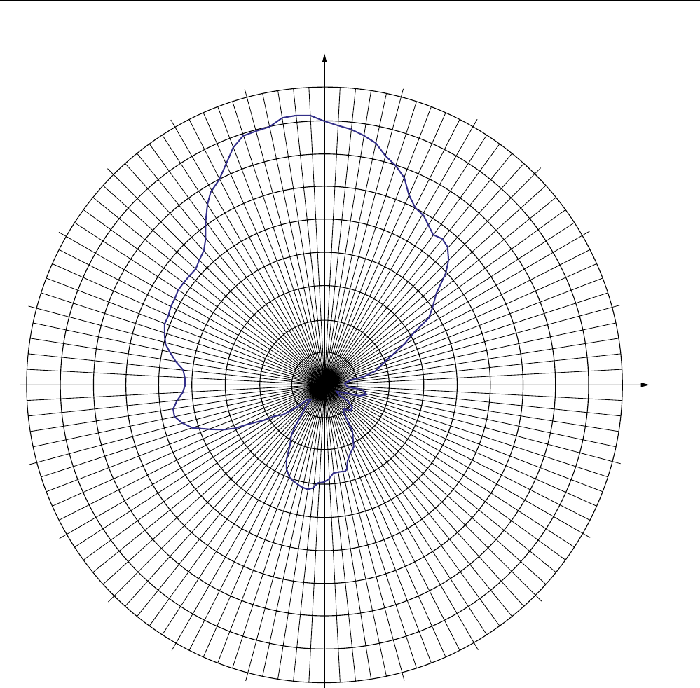
Technical specifications
13.3 Radiation characteristic
Mobile Panel 277F IWLAN
Operating Instructions, 12/2007, A5E01003940-01 319
1 m
2 m
3 m
4 m
5 m
6 m
7 m
8 m
z
15
°
30
°
45
°
60
°
75
°
-15
°
-30
°
-45
°
-60
°
-75
°
105
°
120
°
135
°
150
°
165
°
180
°
-165
°
-150
°
-135
°
-120
°
-105
°
-90
°
x

Mobile Panel 277F IWLAN
Operating Instructions, 12/2007, A5E01003940-01 321
Appendix B
B.1 ESD guideline
Definition of ESD
All electronic modules are equipped with large-scale integrated ICs or components. Due to
their design, these electronic elements are highly sensitive to overvoltage, and thus to any
electrostatic discharge. These electronic components are therefore specially identified as
ESDs.
Abbreviations
The following abbreviation is commonly used for electrostatic sensitive devices:
● EGB – Elektrostatisch Gefährdete Bauteile/Baugruppen (Germany)
● ESD – Electrostatic Sensitive Device (internationally recognized term)
Labeling
ESDs are labeled with the following symbol:
Appendix
B.1 ESD guideline
Mobile Panel 277F IWLAN
322 Operating Instructions, 12/2007, A5E01003940-01
Electrostatic charging
CAUTION
Electrostatic charging
ESDs may be destroyed by voltages far below the level perceived by human beings.
Voltages of this kind develop when a component or an assembly is touched by a person
who is not grounded against static electricity. Usually, it is unlikely that damage to an ESD
as a result of overvoltage is detected immediately but may become apparent only after a
longer period of operation.
Prevent electrostatic charging of your body before you touch the ESD!
Anyone who is not connected to the electrical potential of their surroundings is subjected to
electrostatic charging.
The following figure indicates the maximum electrostatic charge anyone is subjected to when
coming into contact with the materials shown. These values correspond with specifications to
IEC 801-2.
>N9@
>@
9ROWDJH
5HODWLYHKXPLGLW\
① Synthetic materials
② Wool
③ Antistatic materials such as wood or concrete
Protective measures against electrostatic discharge
CAUTION
Observe grounding measures
When working with electrostatic sensitive devices, make sure that the person, the
workplace and the packaging are properly grounded. This helps to avoid electrostatic
charging.

Appendix
B.2 System alarms
Mobile Panel 277F IWLAN
Operating Instructions, 12/2007, A5E01003940-01 323
As a rule, only touch the ESD if this is unavoidable, for example for maintenance. When you
touch modules, make sure that you do not touch the pins on the modules or the PCB tracks.
In this way, the discharged energy cannot reach and damage the sensitive devices.
Discharge electrostatic electricity from your body if you are performing measurements on an
ESD. Do so by touching grounded metallic parts.
Always use grounded measuring instruments.
B.2 System alarms
Mobile Panel 277F IWLAN
Operating Instructions, 12/2007, A5E01003940-01 325
Abbreviations C
C.1 Abbreviations
ANSI American National Standards Institution
CPU Central Processing Unit
CSV Comma Separated Values
CTS Clear To Send
DC Direct Current
DCD Data Carrier Detect
DHCP Dynamic Host Configuration Protocol
DIL Dual-in-Line (electronic chip housing design)
DNS Domain Name System
DP Distributed I/O
DSR Data Set Ready
DTR Data Terminal Ready
IO Input and Output
EAP Extensible Authentication Protocol
ESD Components and modules endangered by electrostatic discharge
EMC Electromagnetic Compatibility
EN European standard
ES Engineering System
ESD Components and modules endangered by electrostatic discharge
GND Ground
HF High Frequency
HMI Human Machine Interface
IEC International Electronic Commission
IEEE Institute of Electrical and Electronics Engineers
IF Interface
IP Internet Protocol
IWLAN Industrial Wireless Local Area Network
LAN Local Area Network
LED Light Emitting Diode
MAC Media Access Control
MOS Metal Oxide Semiconductor

Abbreviations
C.1 Abbreviations
Mobile Panel 277F IWLAN
326 Operating Instructions, 12/2007, A5E01003940-01
MPI Multipoint Interface (SIMATIC S7)
MS Microsoft
MTBF Mean Time Between Failures
n. c. Not connected
OP Operator Panel
PC Personal Computer
PG Programming device
PPI Point-to-Point Interface (SIMATIC S7)
RAM Random Access Memory
PELV Protective Extra Low Voltage
RJ45 Registered Jack Type 45
RTS Request to send
RxD Receive Data
SAR Specific absorption rate
SD Card Security Digital Card
SELV Safety Extra Low Voltage
SP Service Pack
PLC Programmable Logic Controller
SSID Service set identifier
STN Super Twisted Nematic
Sub-D Subminiature D (plug)
TAB Tabulator
TCP/IP Transmission Control Protocol/Internet Protocol
TFT Thin Film Transistor
TKIP Temporal Key Integrity Protocol
TLS Transport Layer Security
TxD Transmit Data
UL Underwriter’s Laboratory
USB Universal Serial Bus
WLAN Wireless Local Area Network
WEP Wired Equivalent Privacy
WINS Windows Internet Naming Service
WPA Wi-Fi Protected Access
Mobile Panel 277F IWLAN
Operating Instructions, 12/2007, A5E01003940-01 327
Glossary
"Transfer" mode
An operating mode of the HMI device in which an executable project is transferred from the
configuring PC to an HMI device.
Access point
The access point is a WLAN participant that also performs administrative functions on the
network.
Acknowledge
Acknowledgment of an alarm confirms that it has been noted.
Ad hoc mode
WLAN network without access point
Alarm logging
Output of user-specific alarms to a printer, in parallel to their output to the HMI device
screen.
Alarm, acknowledging
Acknowledgment of an alarm confirms that it has been noted.
Alarm, activated
Moment at which an alarm is triggered by the PLC or HMI device.
Alarm, deactivated
Moment at which the initiation of an alarm is reset by the PLC.
Alarm, user-specific
A user-specific alarm designates a certain operating status of the plant connected to the HMI
device via the PLC.

Glossary
Mobile Panel 277F IWLAN
328 Operating Instructions, 12/2007, A5E01003940-01
Automation system
Controller of the SIMATIC S7 series such as a SIMATIC S7-300
Bootloader
Used to start the operating system. Automatically started when the HMI device is switched
on. After the operating system has been loaded, the Loader opens.
Configuration software
Software used to generate projects used for the purpose of process visualization. An
example of configuring software is WinCC flexible.
Configuring PC
A configuring PC is a programming device or PC on which plant projects are created using
an engineering software.
CRC
Cyclic redundancy check
Test values contained in a safety message frame can be backed up as follows:
● The validity of the process values contained in the safety message frame
● The accuracy of the assigned address relationships
● The safety-related parameters
Display duration
Defines whether a system alarm is displayed on the HMI device and the duration of the
display.
Effective range
Certain safety-related operator inputs are only possible in a limited area upstream of the
machine or system. This is known as the effective range. To make these inputs, the operator
must log onto this effective range.
EMC
Electromagnetic compatibility is the ability of electrical equipment to function properly in its
electromagnetic environment without influencing this environment.
Event
Functions are triggered by defined incoming events. Events can be configured. Events which
can be assigned to a button include "Press" and "Release", for example.

Glossary
Mobile Panel 277F IWLAN
Operating Instructions, 12/2007, A5E01003940-01 329
Fail-safe
Ability of a technical system to remain in a safe state or switch to another safe state
immediately after certain failures occur.
Fail-safe mode
See Safety mode.
Fail-safe system, F system
Fail-safe systems are used to control processes in which immediate shutdown results in a
safe system state. This means that an immediate shutdown does not result in danger to
people or the environment. F systems are used in systems requiring higher levels of safety.
Field array
Area reserved in configured screens for the input and output of values.
Flash memory
Non-volatile memory with EEPROM chips, used as mobile storage medium or as memory
module installed permanently on the motherboard.
Function keys
Key on the HMI device which supports user-specific functions. A function is assigned to the
key in the configuration. The assignment of the keys may be specific to an active screen or
not.
Half Brightness Life Time
Time period after which the brightness reaches 50% of the original value. The specified
value is dependent on the operating temperature.
Hardcopy
Output of the screen content to a printer.
HMI device
An HMI device is a device used for the operation and monitoring of machines and plants.
The statuses of the machine or plant are indicated by means of graphic elements or by
indicator lamps on the HMI device. The operating elements of the HMI device allow the
operator to interact with the processes of the machine or plant.

Glossary
Mobile Panel 277F IWLAN
330 Operating Instructions, 12/2007, A5E01003940-01
HMI device image
A file that can be transferred from the configuring PC to the HMI device. The HMI device
image contains the operating system and elements of the runtime software required to run a
project.
I/O field
An I/O field enables the input or output of values on the HMI device which are transferred to
the PLC.
Infotext
An infotext is a configured information on objects within a project. Infotext for an alarm, for
example, may contain information on the cause of the fault and troubleshooting routines.
Infrastructure mode
WLAN network with access point
Object
An object is a component of a project. Example: screen or alarm. Objects are used to view or
enter texts and values on the HMI device.
Operating element
Component of a project used to enter values and trigger functions. A button, for example, is
an operating element.
Plant
General term referring to machines, processing centers, systems, plants and processes
which are operated and monitored on an HMI device.
PLC
A PLC is a general term for devices and systems with which the HMI device communicates,
for example SIMATIC S7.
PLC job
A PLC job triggers a function for the PLC at the HMI device.
Process visualization
Visualization of technical processes by means of text and graphic elements. Configured
plant screens allow operator intervention in active plant processes by means of the input and
output data.

Glossary
Mobile Panel 277F IWLAN
Operating Instructions, 12/2007, A5E01003940-01 331
PROFINET
Within the framework of Totally Integrated Automation (TIA), PROFINET represents an
enhancement of the following bus systems:
● PROFIBUS DP as well-established fieldbus
● Industrial Ethernet as the communications bus for the cell level
The experience gained from both systems has been and continues to be integrated in
PROFINET. PROFINET as an Ethernet-based automation standard from PROFIBUS
International (PROFIBUS Nutzerorganisation e.V.) defines a vendor-independent
communications and engineering model.
PROFINET IO controller
Device used to address the connected IO devices. That is: The IO controller exchanges
input and output signals with assigned field devices. The IO controller is often the controller
on which the automation program runs.
PROFINET IO device
A decentralized field device that is assigned to one of the IO controllers (e.g. remote IO,
valve terminals, frequency converters, switches)
PROFINET IO
As part of PROFINET, PROFINET IO is a communication concept that is used to implement
modular, distributed applications.
PROFINET IO allows you to create automation solutions of the type with which you are
familiar from PROFIBUS.
PROFINET IO is implemented by the PROFINET standard for automation devices on the
one hand, and on the other hand by the STEP 7 engineering tool.
This means that you have the same application view in STEP 7 regardless of whether you
configure PROFINET devices or PROFIBUS devices. Programming your user program is
essentially the same for PROFINET IO and PROFIBUS DP if you use the expanded blocks
and system status lists for PROFINET IO.
PROFIsafe
Fail-safe bus profile of PROFINET for communication between the safety program and the F
I/O in an F system.
PROFIsafe address
Every F I/O has a PROFIsafe address. The F I/O uses this address to receive safety
message frames from the F CPU or send safety message frames to the F CPU.

Glossary
Mobile Panel 277F IWLAN
332 Operating Instructions, 12/2007, A5E01003940-01
Project
Result of a configuration using a configuration software. The project normally contains
several screens with embedded system-specific objects, basic settings and alarms. The
project file of a project configured in WinCC flexible is saved under the file name extension
*.hmi.
You need to distinguish between a project on the configuring PC and that on an HMI device.
A project may be available in more languages on the configuring PC than can be managed
on the HMI device. The project on the configuring PC can also be set up for different HMI
devices. Only the runtime project that has been generated for the respective HMI device can
be transferred to it.
Project file
File generated from the runtime project file for use on the HMI device. The project file is
normally not transferred and remains on the configuring PC.
The file name extension of a source file is *.hmi.
Project file, compressed
Compressed format of the project file. The compressed project file can be transferred
together with the runtime project file to the respective HMI device. For this purpose,
backtransfer must be enabled in the project on the configuring PC. The compressed project
file is normally stored on an external memory card.
The file extension of a compressed file is *.pdz.
Proof-test interval
The proof-test interval is the time period after which a component must be put into fail-safe
state. That is, it is replaced by an unused component or it is proven to be completely error-
free.
Recipe
Combination of tags forming a fixed data structure. The data structure configured can be
assigned data on the HMI device and is then referred to as a record. The use of recipes
ensures that all the assigned data is transferred synchronously to the PLC during the
transfer of a record.
Runtime project file
File generated from the project file for a specific HMI device. The runtime project file is
transferred to the corresponding HMI device and used to operate and monitor plants.
The extension of a compressed file is *.pdz.
Runtime software
The runtime software is a process visualization software used to test a project on a
configuring PC.

Glossary
Mobile Panel 277F IWLAN
Operating Instructions, 12/2007, A5E01003940-01 333
Safe state
State of a unit in which safety is assured. In other words, the risk is acceptably low because
it has been established that safety-related malfunctions do not occur or because of the
safety measures taken to prevent possible safety-related malfunctions.
The basic principle of the safety concept in a fail-safe system is the existence of a safe state
for all process variables.
Safety function
Safety function is a mechanism integrated in fail-safe I/Os and CPUs, enabling them to be
used in fail-safe systems. In accordance with IEC 61508: A safety function is implemented
by a safety system to ensure that the system is kept in a safe state or brought into a safe
state in the event of a particular fault. (user safety function)
Safety integrity level
Safety integrity level (SIL) in accordance with IEC 61508 and prEN 50129. The higher the
safety integrity level, the more comprehensive are the measures to avoid systematic errors
and control systematic errors and random hardware failures.
Safety mode
Operating mode of the HMI device in which safety-related communication can be performed
via safety message frames.
Safety-related communication
Communication used to exchange fail-safe data.
Screen
Form of the visualization of all logically related process data for a plant. The visualization of
the process data can be supported by graphic objects.
Screen object
Configured object used to display or operate the plant, for example a rectangle, I/O field or
alarm view.
STEP 7
STEP 7 is the programming software for SIMATIC S7, SIMATIC C7 and SIMATIC WinAC
PLCs.
Symbolic I/O field
A symbolic I/O field is a field for the input and output of the value. Contains a list of default
entries from which one can be selected.

Glossary
Mobile Panel 277F IWLAN
334 Operating Instructions, 12/2007, A5E01003940-01
System alarm
A system alarm is assigned to the "System" alarm class. A system alarm refers to internal
states on the HMI device and the PLC.
Tab sequence
During configuration, this defines the sequence in which objects are activated on pressing
the <TAB> key.
Tag
Defined memory location to which values can be written to and read from. This can be done
from the PLC or the HMI device. Based on whether the tag is interconnected with the PLC or
not, we distinguish between "external" tags (process tags) and "internal" tags.
Transfer
Transfer of a runtime project from the configuring PC to the HMI device.
Transponder
A transponder is a – usually wireless – communications, display or control device that
receives incoming signals and automatically responds to them. The term transponder is
derived from transmitter and responder. Transponders can be passive or active.
Zone
A zone is a defined area in the system. The HMI device recognizes the zone it is in. When
entering and leaving the zone, the HMI device can display a specific system image. This
allows zone-specific operator inputs to be disabled or enabled.
Mobile Panel 277F IWLAN
Operating Instructions, 12/2007, A5E01003940-01 335
Index
"
"Override" mode, 226
/
/Audit, 32
A
Acceptance, 196
Effective ranges and transponders, 196
Plant, 196
Accessories
Accessory kit, 20, 23, 26
Accessory kit, 20
Charging station, 23
Transponder, 26
Acknowledge
Alarm, 276
Error alarm, 276
Activate
Password protection, 146
Ad hoc mode, 58
Address assignment
TCP/IP network, 169
Addressing, 167
Admin, 268, 269
Agency, 7
Alarm, 271
Acknowledge, 276
Alarm indicator, 272
Display, 273
Editing, 276
Functional scope, 29
Alarm buffer, 272
Functional scope, 29
Alarm class, 271, 274
Alarm event, 271
Alarm group, 272
Alarm indicator, 272
Alarm line, 273
Alarm log, 272
Alarm report, 272
Alarm view, 273
Extended, 274
Simple, 273
Alarm window, 275
ALARM_S, 29
Alphanumerical
Screen keyboard, 242
Alphanumerical value
Changing, 242
Entering, 242
Ambient conditions
Climatic, charging station, 53
Climatic, HMI device, 53
Climatic, transponder, 53
Tested for, 52
Application case
Unattended in effective range, 220, 225, 233
Applications
Mobile Panel 277F IWLAN, 17
Australia
Approvals, 38
Authorization, 262
Automatic
Transfer, 191
Automation License Manager, 215
B
Backlighting
Reducing, 152
Setting, 137
Backtransfer, 190, 193
Backup, 136, 178, 188, 200, 201, 203, 262
Registry information, 136, 150
Temporary files, 150
to external memory medium, 136
To external storage device, 177
To memory card, 177
With ProSave, 203
With WinCC flexible, 201
Backup time
Internal clock, 310
Bar, 251
Basic knowledge

Index
Mobile Panel 277F IWLAN
336 Operating Instructions, 12/2007, A5E01003940-01
Required, 4
BAT
LED, 98
BAT 1
LED, 122
BAT 2
LED, 122
Batteries
Charging in the charging compartment, 120
Battery, 246
Application, 246
Charging options, 22
Layout, 246
LED display, 87
Maintenance cycle, 301
Operation, 246
Purpose, 22
State, 181
Battery charging status
Vibration alarm, 159
Battery status
Display, 87, 136
BGIA approval, 38
Booting, 156
Bridging battery, 21, 22
Changing, 89
Insert, 85
Safety instruction, 88, 90
Brightness
Changing, 152
Browser
Homepage, 136
Setting, 136
Byte assignment
Direct keys, 107
C
Calibrating
Touch screen, 144
Care, 301
CE approval, 37
Certificate
Delete, 136, 176
Display, 136
Importing, 136, 176
Certificates, 136
Certifications, 37
Changing
Brightness, 152
Screen setting, 152
User data, 268
Character repeat, 136
Screen keyboard, 141
Setting, 141
Charging
Electrostatic, 322
Charging options
Battery, 22
Charging station, 21
Charging compartment, 120
Clearance, 55
Configuration, 22
EMC-compliant installation, 46
LED display, 122
Lock, 123
Main dimensions, 307
Mounting location, 54
Mounting position, 66
Charging status of battery
Vibration alarm, 159
Climatic
Transport conditions, 48
Closing
Project, 269
Column sequence
Alarm view, 274
COM
LED, 97
Commissioning engineers, 3
Communication error, 29, 233
Compatibility conflict, 201
Configuration phase, 24
Configure
Network, 168
Operating system, 125
Screen keyboard, 136, 140
Configuring PC, 24
Connecting, 78
Connection graphic, 78
Connecting
Configuring PC, 78
PLC, 79
Printer, 80
USB device, 81
Connection
Electrical, 69
Connection graphic
Configuring PC, 78
PLC on Mobile Panel, 80
Printer, 80
Connection to PLCs
Number, 32
Control Panel

Index
Mobile Panel 277F IWLAN
Operating Instructions, 12/2007, A5E01003940-01 337
Open, 135
Operating, 137
Password protection, 127
Screen keyboard, 138
Cookies, 136, 175
Country code, 129
CRC checksum
Determining, 197
Creating
Recipe data record, 285, 292
Users, 266
Currency, 137
D
Data channel
Enabling, 160
Locking, 160
Parameter assignment, 137, 160
Data flow, 280
Data record list, 281, 291
Data transfer rate
to Access Point, 130
Date, 136
Entering, 243
Setting, 147
Synchronizing, 148
Date format, 137, 149
Date/time properties, 136, 147
Deactivating
Password protection, 147
Decimal, 241
Default Gateway, 170
Degree of protection
Safety instruction, 76, 79, 178, 205
Delay time
Setting, 137, 162
Delete
Certificate, 176
Recipe data record, 287, 294
Users, 269
Design variations, 18
Device name
For network operation, 168
Setting, 137
DHCP, 170
Direct key, 107, 234
Bit coding, 108
Byte assignment, 107
Functional scope, 31
Reaction time, 110
Display
Alarm, 273
Battery status, 87
HMI device information, 136
Infotext, 244, 275
Memory information, 159
Specifications, 308
System information, 158
Display format, 240
Disposal, 7
DNS, 170
Server, 167
Documentation
Conventions, 6
Enclosed, 65
Getting started, 4
Operating instructions, 5
User manual, 4
Double-click, 136
Setting, 143
Drop down list box, 244
E
EC Declaration of Conformity, 37
Editing
Alarm, 276
Recipe data record, 286, 293
Effective range
Calculating quality, 249
Detect, 62
Leaving without logging off, 225
Logoff, 226
Logon, 224
Effective range name, 247
Layout, 247
Effective range quality, 248
Application, 248
Operation, 249
Effective ranges, 27
Acceptance, 196
Forming, 62
Rules, 58, 63
Specifying, 64
Testing, 199
Electrical
Installation, 69
Electrostatic charging, 322
Electrostatic discharge
Precautions, 322
Element list, 281, 292
E-mail
Setting, 137, 172

Index
Mobile Panel 277F IWLAN
338 Operating Instructions, 12/2007, A5E01003940-01
EMC, 46
Guideline, 37
Emergency stop, 220
Emergency stop button
Effectiveness, 40, 44
Operating, 43, 101
Release, 101
Safety instruction, 43
Emission, 42, 47
Enabling button, 44, 102
Operating, 103
Panic activation, 104
Risk from improper use, 46
Safety instruction, 46
Switch settings, 103
Enabling device, 44
Encryption, 175
Entering
Alphanumerical value, 242
By means of function key, 237
Date, 243
Numerical value, 241
Recipe data record, 298
Symbolic value, 244
Text box, 239
Time, 243
Error alarm
Acknowledge, 276
Error display
Red, 233
ESD
Abbreviations, 321
Labeling, 321
Safety instruction, 68
Ethernet settings
IP address, 170
Evaluation
Operator control, 96
Exporting
Recipe data record, 296
Extended alarm view, 274
Extended recipe view, 281
Extended user view, 264
External memory medium
Backup to, 177
Restoring from, 177
F
Factory settings
Resetting to, 205
Fail-safe
Automation system, 28
Using the HMI device, 28
Fail-safe mode
Specifications, 310
Feedback
Optical, 236
Front view, 18, 305
Function keys
Global function assignment, 237
Input via, 237
Labeling, 116
Local function assignment, 237
Function test, 93, 301
Functional scope
Alarm buffer, 29
ALARM_S, 29
Alarms, 29
Device-specific, 32
Graphics list, 29
Infotext, 31
Limit value monitoring, 29
Log, 30
Recipe, 30
Safety, 31
Scaling, 29
Screen, 30
Tag, 29
Text list, 29
Functions
Additional, 31
G
Gauge, 251
Global rampdown, 221
Graphics list
Functional scope, 29
H
Handwheel
Application, 111
Evaluate incremental values, 111
Operating, 104
Reaction time, 110
High frequency radiation, 36
HMI device
Emergency stop button, 100
Enabling button, 102
Holding, 118, 119
Information, 136, 157

Index
Mobile Panel 277F IWLAN
Operating Instructions, 12/2007, A5E01003940-01 339
Ports, 76, 309
Restart, 156
Restarting, 136
Specifications, 308
Storing, 219
Switch off, 93
HMI Input Panel
Options, 140
Homepage
Internet, 174
Host cable
Safety instruction, 78
I
Identification, 171
Illuminated pushbutton
Application, 112
Bit assignment, 112
Operating, 106
Importing
Certificate, 176
Recipe data record, 297
Infotext
Display, 244, 275
Functional scope, 31
Initial startup, 189
Input Panel, 136
Input unit, 96
Specifications, 309
Installation
Electrical, 69
EMC-compliant, 46
Installing
Option, 188, 212, 213, 214
Integrating, 222
Interference
Pulse-shaped, 46
Sinusoidal, 47
Internal clock, 148, 310
Internal error, 233
Internet
Homepage, 174
Options, 136
Search engine, 174
Security settings, 136
Service, 7, 303
Settings, 137, 172
Support, 7, 303
Internet Explorer, 127
Internet options
Privacy, 175
IP address
Ethernet, 170
Setting, 136
K
Key control
Trend view, 256
Keyboard
Safety instruction, 96
Keyboard properties, 136, 141
Key-operated switch
Application, 112
Bit assignment, 112
Operating, 105
L
Labeling
Function keys, 116
Labeling strips, 20
Attaching, 117
Dimensions, 117
Exchange, 118
Printing, 117
LAN connection, 136
Language change
Functional scope, 31
Layout
Battery, 246
Slider control, 252
Sm@rtClient view, 259
Trend view, 255
Leaving the effective range
Vibration alarm, 159
LED
BAT, 98
BAT 1, 122
BAT 2, 122
COM, 97
POWER, 122
PWR, 97
RNG, 98
SAFE, 97
LED display
Battery, 87
Charging station, 122
Mobile Panel, 96
LED function key
Application, 110
Bit assignment, 111

Index
Mobile Panel 277F IWLAN
340 Operating Instructions, 12/2007, A5E01003940-01
License key, 215
Transferring, 189, 216
Transferring back, 189, 217
Limit value
For password, 263
For user, 263
For user view, 263
Limit value monitoring
Functional scope, 29
Limit value test, 241
Loader
Buttons, 125
Open, 126
Local rampdown, 221
Log
Functional scope, 30
Logbook
WLAN connection, 134
Logoff
Effective range, 226
Users, 266
Logoff time, 262
Logon
Effective range, 224
Users, 264
Logon data, 171
M
Main battery, 21, 22
Changing in good time, 88
Insert, 86
Main battery change
Block of USB interface, 82
Main dimensions
Charging station, 307
Mobile Panel 277F IWLAN, 305
Transponder, 308
Maintenance, 301, 302
Maintenance technicians, 3
Manual
Production sequence, 299
Transfer, 190
Measures
Organizational, 219
Mechanical
Transport conditions, 48
Memory
Specifications, 309
Memory card, 21
Inserting, 115
Restoring file system, 150
Unplug, 116
Memory information, 137
Display, 159
Memory management, 136, 182
Mobile Panel
Applications, 17
Design variations, 18
Front view, 18
Information, 157
LED display, 96
Ports, 76
Rear view, 19
Side view, 19
Switching on, 91
Testing, 91
Mobile Panel 277F IWLAN
Main dimensions, 305
Monitor setting
Changing, 136
Monitoring mode
Sm@rtClient view, 259
Mounting location
Charging station, 54
Mounting position
Charging station, 66
Mouse properties, 136, 143
Multi-key operation, 236, 237
Multimedia card, 21, 114
N
Name server, 170
Setting, 136
Network
Configure, 168
Logon data, 136
Set up, 167
Setting, 169
Network & dial-up connections, 136
Network and dial-up connections, 136
Network ID, 136
Network operation
Device name, 168
Options, 136, 137, 172
Nominal voltage, 57
NOTE
License key, 212
Number format, 137, 149
Numerical
Screen keyboard, 240
Numerical value
Changing, 241

Index
Mobile Panel 277F IWLAN
Operating Instructions, 12/2007, A5E01003940-01 341
Decimal places, 241
Display format, 240
Entering, 241
Limit value test, 241
O
Offices, 7
Offline
Operating mode, 186
Recipe tag, 284
Test, 195
Online
Operating mode, 187
Recipe tag, 284
Test, 195
OP properties, 136
Device, 157
Memory monitoring, 182
Persistent storage, 150
Touch, 144
Open
Loader, 126
Operating
Control Panel, 137
Emergency stop button, 43, 101
Enabling button, 103
Feedback, 236
Handwheel, 104
Illuminated pushbutton, 106
Key-operated switch, 105
Recipe menu, 292
Recipe screen, 285, 292
Safety instruction, 119
Slider control, 253
Switches, 254
Trend view, 255
With external keyboard, 235
With external mouse, 235
Operating instructions
Purpose of, 3
Scope, 4
Operating mode, 186
Changing, 186
Offline, 186
Online, 187
Transfer, 92, 187
Operating safety
Standards, 39, 43
Operating system
Configure, 125
Update via ProSave, 207
Updating, 204, 205
Updating using WinCC flexible, 206
Operation
Battery, 246
Operation feedback, 236
Operator control
Evaluation, 96
Functions, 96
Recipe view, 285
Selection, 96
Simple recipe view, 291
Operators, 3
Optical feedback, 236
Option
Installing, 188, 212
Installing with ProSave, 214
Installing with WinCC flexible, 213
Removing, 188, 212
Removing with ProSave, 215
Removing with WinCC flexible, 213
Options, 32
Network operation, 136, 137, 172
P
Panic activation
Enabling button, 104
Parameter assignment
Data channel, 137, 160
Password, 262
Backup, 262
Restoring, 262
Specifying, 146
Password list, 262
Password properties, 137, 146
Password protection, 127, 137
Activate, 146
Deactivating, 147
PELV, 41
Peripherals
Rated load, 82
Permission in remote control, 260
Pin assignment
RJ45 socket, 313
USB socket, 313
Plant
Acceptance, 196
PLC
Connecting, 79
Connection graphic, 80
Number, 32
Reading recipe data record, 289, 295

Index
Mobile Panel 277F IWLAN
342 Operating Instructions, 12/2007, A5E01003940-01
Transferring recipe data record, 290, 295
PLC, 32
PLC_User, 268, 269
Ports, 76
HMI device, 309
POWER
LED, 122
Power failure, 201, 205
Power Save 1, 98, 152
Power Save 2, 98, 152
Power supply, 41
Charging station, 41
Tabletop power supply unit, 41
Precautions
Electrostatic discharge, 322
Printer
Connecting, 80
Connection graphic, 80
Setting, 137
Printer connection
Setting, 154
Printer properties, 137, 154
Printing
Labeling strips, 117
Via network printer, 168
Production sequence
Manual, 299
PROFINET, 167
Addressing, 167
PROFINET IO
Disabling direct keys, 165
Enabling direct keys, 165
Setting, 137
PROFIsafe, 33
PROFIsafe address
Setting, 137
Project
Closing, 269
Offline testing, 195
Reuse, 187
Testing online, 195
Transferring, 188, 189
Project file, compressed
Memory location, 163
Proper use, 35
Protection against ingress of solid foreign bodies, 57
Protection against water, 57
Protective foil, 20
Protocol, 33
Proxy
Server, 136, 172, 174
Setting, 136
PWR
LED, 97
R
Radiation
High frequency, 36
Radio interference, 42
Emission, 47
Rampdown
Safety instruction, 118
Rate Control, 130
Rated load
USB interface, 82
Reading
Recipe data record, 289
Reading out
Recipe data record, 295
Real-time clock
Internal, 148
Rear view, 19
Recipe, 277
Control, 279
Data flow, 280
Data record, 278
Field of application, 277
Functional scope, 30
Recipe screen, 280
Recipe view, 280
Synchronizing tags, 288
Recipe data record
Creating, 285, 292
Delete, 287, 294
Editing, 286, 293
Entering, 298
Exporting, 296
Importing, 297
Reading from PLC, 289, 295
Synchronize with PLC, 286
Transferring to PLC, 290, 295
Recipe list, 281, 291
Recipe menu
Operating, 292
Recipe screen, 282
Operating, 285, 292
Overview, 282
Recipe tag
Offline, 284
Online, 284
Synchronizing, 283, 288
Recipe view, 280
Extended, 281

Index
Mobile Panel 277F IWLAN
Operating Instructions, 12/2007, A5E01003940-01 343
Menu items, 291
Operator control, 285, 291
Simple, 281
Recommissioning, 189
Recycling, 7
Red error display, 233
Regional and language settings, 137, 149
Regional settings, 149
Registered trademarks, 6
Registry information
Backup, 136, 150
Regulations for the prevention of accidents, 35
Remote control
Forcing permission, 260
Start, 260
Removing, 223
Option, 188, 212, 213, 215
Repairs, 302
Replacement key set, 303
Reset button, 77
Resetting to factory settings with ProSave, 210
Resetting to factory settings with WinCC flexible, 208
Restore, 136, 178
Restoring, 188, 200, 202, 203, 262
From external memory medium, 136
From external storage device, 177
From memory card, 150
With ProSave, 203
With WinCC flexible, 202
Restoring factory settings, 79, 188, 205
Return Center, 302
Risk analysis, 43
Risk evaluation
Special mode, 45
Risk from improper use
Enabling button, 46
RJ45 socket
Safety instruction, 77
RNG
LED, 98
Rotary coding switch
Transponder, 66
Ruler
Trend view, 255
S
S7, 32
SAFE
LED, 97
Safe electrical separation, 41
Safe state, 28
Safety
Functional scope, 31
Standards, 39, 43
Safety instruction, 35, 114
Backlighting, 153
Bridging battery, 88, 90
Category 0 Stop, 44
Category 1 Stop, 44
Changed tag name, 288
Compatibility conflict, 201
Compressed project file, 190
Data channel, 206
Data loss, 205
Degree of protection, 178
Degree of protection, 76, 79
Degree of protection, 205
Direct key, 234
Electrostatic charging, 322
Emergency stop button, 36, 43, 54, 71, 84, 101, 114
Enabling button, 36, 45, 46
ESD, 68
General, 42
High frequency radiation, 36
Impact effect, 36
Keyboard, 96
Leaving the WLAN coverage area, 234
License keys, 205
Malfunctions, 84
Memory card, first use, 116
Memory distribution, 159
Multi-key operation, 236
Observe grounding measures, 322
Operating the HMI device, 119
Path, 163
Power failure, 201, 205
Power supply, 41
Preventing inadvertent operation, 301
Project file, 163
Rampdown, 118
Recipe data record in the background, 282
Restart, 156
RJ45 socket, 77
Sample cycle time, 110
Shutdown, 225
Storage, 48
Switching infotext, 245
Time-dependent reactions, 149
Touch screen, 96
Transfer mode, 162
Transfer mode channel 2, 162
Transport, 48
Unintentional action, 238

Index
Mobile Panel 277F IWLAN
344 Operating Instructions, 12/2007, A5E01003940-01
USB connection sequence, 78
USB Host-to-Host cable, 78
USB interface, 82
SAR, 47
Scaling
Functional scope, 29
Scope of delivery, 65
Screen
Functional scope, 30
Screen keyboard, 136, 239
Adjust size, 139
Alphanumerical, 242
Change layout, 139
Character repeat, 141
Configure, 140
For Control Panel, 138
Keyboard level, 242
Language change, 242
Move, 139
Numerical, 240
Representation types, 138
Screen saver, 137, 153
Setting, 152
Screen setting
Changing, 152
Search engine
Internet, 174
Security settings, 136
Security system, 261
Selection
Operator control, 96
Service
On the Internet, 7, 303
Service pack, 302
Service technicians, 3
Set up
Network, 167
Setting
Backlighting, 137
Browser, 136
Character repeat, 141
Date, 147
Date format, 149
Date/Time, 136
Delay time, 137, 162
Device name, 137
Double-click, 143
E-mail, 137
E-mail connection, 172
IP address, 136
Language, 238
Name server, 136
Network, 169
Number format, 149
Printer connection, 154
PROFINET IO, 137
PROFIsafe address, 137
Proxy, 136
Regional data, 149
Screen saver, 152
Time, 147
Time format, 149
Transponder ID, 68
Setting language, 238
Settings
Internet, 137
Language, 137
Regional, 137
Shutdown, 221
Safety instruction, 225
Side view, 19, 306
Siemens HMI input panel options, 136
SIMATIC Logon, 262
SIMATIC S7, 32
Simple alarm view, 273
Simple recipe view, 281
Menu items, 291
Operator control, 291
Simple user view, 264
Slider control, 252
Sm@rtAccess, 32
Sm@rtClient view, 259, 260
Monitoring mode, 259
Usage, 259
Sm@rtService, 32
SMTP server, 172
Software options, 32
Sort order
Alarm view, 274
Special mode
Risk evaluation, 45
Specifications
Display, 308
Fail-safe mode, 310
HMI device, 308
Input unit, 309
Memory, 309
Supply voltage, 309, 312
Weight, 312
Standard input unit, 96
Standards, 38
Start
HMI device, 156
Status Force, 256

Index
Mobile Panel 277F IWLAN
Operating Instructions, 12/2007, A5E01003940-01 345
Touch operation, 258
Stop
Safety instruction, 44
Subnet Mask, 170
Supply voltage, 312
Specifications, 309
Support
On the Internet, 7, 303
Switch off
HMI device, 93
Switch setting
Enabling button, 103
Switches, 253
Switching on
Mobile Panel, 91
Switch-off behavior
Emergency stop, 220
Global rampdown, 221
In the plant, 220
Local rampdown, 221
Shutdown, 221
Trigger, 221
Symbolic value
Changing, 244
Entering, 244
Synchronizing
Date and time, 148
Recipe tag, 283, 288
System, 158
Acceptance, 196
System functions, 107
System information, 137
Display, 158
System properties, 137
Device name, 168
General, 158
Memory, 159
T
Tabletop power supply unit, 21, 77
Connecting, 82
Tag
Functional scope, 29
Task planner
Functional scope, 31
TCP/IP address, 169
Technical support, 7
Temporary files
Backup, 150
Test
For ambient conditions, 52
Test voltages, 56
Testing
Mobile Panel, 91
Text box, 239
Text list
Functional scope, 29
Time, 136
Entering, 243
Setting, 147
Synchronizing, 148
Time format, 137, 149
Time zone
Setting, 147
Time-dependent reactions, 149
Touch operation
Trend view, 256
Touch screen
Calibrating, 136, 144
Safety instruction, 96
Training center, 7
Transfer, 187, 189, 190
Automatic, 191
Cancel, 92
Manual, 190
Transfer settings, 137, 160
Transfer Settings
Channel, 160
Directories, 162
Transferring
License key, 189, 216
Project, 188, 189
Recipe data record, 290, 295
Transferring back
License key, 189, 217
Transponder, 21
Acceptance, 196
Detect, 62
Inserting the battery, 68
Installation, 69
Main dimensions, 308
Rotary coding switch, 66
Rules, 60
Rules, 60
Transponder ID
Setting, 68
Transport conditions, 48
Transport damage, 65
Trend view, 254
Key control, 256
Touch operation, 256
Trends
Functional scope, 31

Index
Mobile Panel 277F IWLAN
346 Operating Instructions, 12/2007, A5E01003940-01
Limit violation, 255
TÜV, 38
U
UL approval, 37
Unattended in effective range
Application case, 220, 225, 233
Unintentional action, 236, 238
Updating
About ProSave, 207
Operating system, 204
Using WinCC flexible, 206
Updating the operating system, 188
Usage
Conditions, 51
Geographical, 42
In industry, 42
In residential areas, 42
With additional measures, 51
USB
Connection sequence, 78
USB connection sequence
Safety instruction, 78
USB device
Connecting, 81
USB FlashDrive, 21
USB interface
Block during main battery change, 82
Rated load, 82
USB socket, 77
Pin assignment, 313
USB stick, 21
User data
Backup, 262
Changing, 268
Restoring, 262
User group, 262
User manual, 4
User name, 171
User view, 263
Extended, 264
Simple, 264
Users, 262
Admin, 268, 269
Creating, touch operation, 266
Delete, 269
Logoff, 266
Logon, 264
PLC_User, 268, 269
V
Value table
Trend view, 255
VBScript
Functional scope, 31
Vibration alarm, 136
Activate, 159
W
Weight, 312
WinCC flexible internet settings, 137
E-mail, 172
Windows CE taskbar, 125
Password protection, 127
WINS, 170
Server, 167
Wireless approval, 38
WLAN
Authentication, 133
Encryption, 133
Interface, 313
Network key, 133
Password, 133
WLAN connection
Logbook, 134
WLAN network
Connect, 132
WLAN networks
Connection sequence, 133
Creating new, 132
Display available, 131
Parameter assignment, 132
WLAN quality, 246
Application, 246
Operation, 247
WLAN range, 27
Z
Zone
Calculating quality, 250
Detect, 62
Zone name, 249
Layout, 249
Operation, 250
Zone quality, 250
Application, 250
Layout, 250
Operation, 251
Zones

Index
Mobile Panel 277F IWLAN
Operating Instructions, 12/2007, A5E01003940-01 347
Rules, 59
Testing, 200