Siemens BLUEVCIBT BlueVCI Vehicle Diagnostic Interface User Manual
Siemens AG BlueVCI Vehicle Diagnostic Interface
Siemens >
User Manual

Edition 02/2007
Version V1.5
A5E00727814
Copyright © 2007 SIEMENS AG All rights reserved.
Weitergabe sowie Vervielfältigung dieser Unterlagen, Verwertung und Mitteilung ihres Inhalts
sind nicht gestattet, soweit nicht ausdrücklich zugestanden. Zuwiderhandlungen verpflichten zu
Schadenersatz. Alle Rechte für den Fall der Patentierung und der GM-Eintragung vorbehalten.
Copying of this document and giving it to others and the use or communication of the
contents thereof are forbidden without written permission. Offenders are liable to the
payment of damages. All rights are reserved in the event of the grant of a patent or the
registration of a utility model or design.
s
Hardware Operating Manual
BlueVCI

Contents
BlueVCI Hardware Operating Manual 1 of 21
Edition 02/2007
Version V1.5
A5E00727814
Contents
1 General information ............................................................................................ 5
1.1 Overview............................................................................................................ 5
1.2 Safety instructions ............................................................................................. 5
1.3 Declaration of Conformity .................................................................................. 5
1.4 FCC approval..................................................................................................... 6
1.5 Designated use.................................................................................................. 7
1.6 Areas of applications ......................................................................................... 7
2 Design and function............................................................................................ 8
2.1 BlueVCI Vehicle Diagnostic Interface................................................................ 8
2.1.1 Scope of delivery .................................................................................... 8
2.1.2 Order options .......................................................................................... 9
3 Interfaces and display....................................................................................... 10
3.1 LED display...................................................................................................... 10
3.2 OBD Connector Assembly (OCA) ................................................................... 11
3.3 Communication interfaces ............................................................................... 12
4 Mechanical design ............................................................................................ 13
5 Function ............................................................................................................. 14
5.1 Startup ............................................................................................................. 14
5.2 Operation ......................................................................................................... 14
6 Troubleshooting and Self-Test ........................................................................ 15
6.1 Self-Test........................................................................................................... 15
6.2 Symptoms, causes and solutions.................................................................... 15
7 Maintenance and support................................................................................. 16
7.1 Visual inspection.............................................................................................. 16
7.2 Firmware update.............................................................................................. 16
7.3 Replacing the diagnostic plug.......................................................................... 16
8 Technical data ................................................................................................... 17
8.1 BlueVCI............................................................................................................ 17
8.2 USB cable........................................................................................................ 18
9 Glossary ............................................................................................................. 19
9.1 Abbreviations ................................................................................................... 19
Safety instructions
2 of 20 BlueVCI Hardware Operating Manual
Edition 02/2007
Version V1.5
A5E00727814
Safety instructions
Explanation of symbols
The safety instructions in the operating manuals, the scope of delivery or any other
documentation provided and on the products themselves use symbols that have the
following meanings:
Caution!
Texts with this symbol contain information relating to your safety and how you can
reduce the risk of fatal or serious injury.
The CAUTION symbol indicates that particular attention is required to ensure
your safety.
Warning!
Texts with this symbol contain information about how you can prevent damage to
the vehicle and to the equipment.
The Warning symbol informs you that failure to observe the instructions provided
can result in damage to the vehicle and/or the equipment.
Note
Texts with this symbol contain additional useful information.
A Note symbol also contains special additional instructions for using the equip-
ment and other associated information.
Reference to other safety instructions
The general safety instructions are specified below. The operating manuals also
contain additional safety instructions. You must read these operating manuals
before use.
Safety instructions
BlueVCI Hardware Operating Manual 3 of 21
Edition 02/2007
Version V1.5
A5E00727814
IMPORTANT SAFETY INSTRUCTIONS
1. Caution!
Read all instructions thoroughly.
2. Caution!
If the device is damaged, it may not be used until it has been inspected by a
qualified specialist.
3. Caution!
To prevent electric shock, you may not use the device on wet surfaces or expose it
to rainfall.
4. Caution!
Do not allow any cables or leads to hang over the edges of desks, benches or
consoles. Avoid contact between the cables or leads and hot parts or rotating fans.
5. Caution!
Use of extension cables is not permitted. Only the specified cables and leads may
be used for testing purposes.
6. Caution!
The device may not be operated close to open fuel tanks as this could cause a risk
of explosion or fire.
Safety instructions
4 of 20 BlueVCI Hardware Operating Manual
Edition 02/2007
Version V1.5
A5E00727814
7. Caution!
When working on combustion engines, you must ensure adequate ventilation.
8. Caution!
Only use the device as described in the manual. Only use the accessories specified
by the manufacturer.
9. Caution!
Risk of explosions
The device has internal sparking components and may not therefore be exposed to
any flammable vapours. The device should be operated at least 460 mm (18”)
above the ground as gasoline and other vapours settle on the ground.
10. Caution!
Opening the device or accessories without authorisation and improper interference
with the device can result in significant hazards for you and for the device itself.
Note
To assure an undisturbed radio communication it is necessary to cover the USB
connector by the cap
RETAIN THESE INSTRUCTIONS!
Status: 2007

General information
BlueVCI Hardware Operating Manual 5 of 21
Edition 02/2007
Version V1.5
A5E00727814
1 General information
1.1 Overview
This operating manual contains the necessary information for proper use of the
“Bluetooth Vehicle Communication Interface BT” and “Bluetooth Vehicle
Communication Interface WLAN”, referred to in the text as “BlueVCI” for short.
Knowledge of and technically correct application of the safety instructions and
warnings in this operating manual are essential for hazard-free startup and to ensure
safety during operation and maintenance of the BlueVCI.
For reasons of clarity, the operating manual does not include all details of the
hardware and cannot cover every conceivable startup, operation, maintenance and
support.
1.2 Safety instructions
Follow the safety instructions for the BlueVCI. These can be found on the rear of the
device and in this operating manual after the contents and at all relevant items in the
text.
1.3 Declaration of Conformity
Herewith Siemens AG declares that the device BlueVCI BT
is in compliance with the requirements and provisions of the
EU Directive 1999/5/EC.
A copy of the complete Declaration of Conformity can be retrieved from:
Siemens AG
A&D AS AP TE SF
Siemensallee 84
D-76187 Karlsruhe

General information
6 of 20 BlueVCI Hardware Operating Manual
Edition 02/2007
Version V1.5
A5E00727814
1.4 FCC approval
Warnungen in Bezug auf eingebauten Bluetooth-Sender/-Empfänger:
1. Warning!
FCC 15.19: This device complies with Part 15 of the FCC Rules and with RSS-210
of Industry Canada.
Operation is subject to the following two conditions:
1. This device may not cause harmful interference, and
2. This device must be able to accept any interference received, including
interference that may cause undesired operation.
2. Warning!
FCC 15.21: Changes or modifications made to this equipment not expressly
approved by the manufacturer may void the FCC authorization to operate this
equipment.
3. Warning!
This equipment complies with FCC radiation exposure limits for an uncontrolled
environment. This equipment should be installed and operated with minimum
distance 20 cm between the radiator and your body.
This transmitter must not be moved or operate in conjunction with any other
antenna or transmitter.

General information
BlueVCI Hardware Operating Manual 7 of 21
Edition 02/2007
Version V1.5
A5E00727814
Siemens AG BlueVCI
FCC ID: LYHBLUEVCIBT
IC: 267AA-BLVCIBT
This device complies with Part 15 of the FCC Rules and with RSS-210 of Industry
Canada. Operation is subject of the following two conditions. (1) this device may not
cause harmful interference, and (2) this device must accept any interference
received, including interference that may cause undesired operation.
1.5 Designated use
• The BlueVCI is suitable for use on vehicles, test benches etc.
• The product described has been developed, manufactured and tested in
compliance with the applicable safety standards. Observance of the safety
instructions, specified start-up procedure, designated use and the
recommended maintenance and care information results in no hazards likely to
cause material damage or personal injury under normal circumstances.
1.6 Areas of applications
The BlueVCI is connected to a diagnostic interface and, in conjunction with an
application, enables wireless communication with a host computer.
The device is designed to be configurable for specific applications. This applies to the
mechanical and electrical diagnostic interface and to the protocols and software
control as well.
The device is designed to be application neutral. It allows the user to realise an
individual solution tailored to his specific requirements.
Design and function
8 of 20 BlueVCI Hardware Operating Manual
Edition 02/2007
Version V1.5
A5E00727814
2 Design and function
This section provides a basic description of all BlueVCI components.
Versions
1. BlueVCI BT with Bluetooth communication
2. BlueVCI WLAN with WLAN communication
2.1 BlueVCI Vehicle Diagnostic Interface
The BlueVCI is dedicated for mobile operation in a workshop. It is connected to a
vehicle via a diagnostic plug and provides electronic support for troubleshooting and
fault finding.
The BlueVCI is powered by the vehicle battery via the diagnostic plug or from a
computer system (PC, laptop or vehicle tester) via USB cable. Communication is
either wireless or via the USB connection.
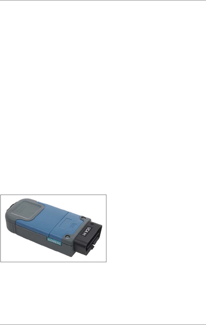
2.1.1 Scope of delivery
The BlueVCI consists of the following major components:
1. BlueVCI device
2. USB cable, type A-B (0.5 m)
3. Documentation CD-ROM
Bild 2-1 BlueVCI device
Design and function
BlueVCI Hardware Operating Manual 9 of 21
Edition 02/2007
Version V1.5
A5E00727814
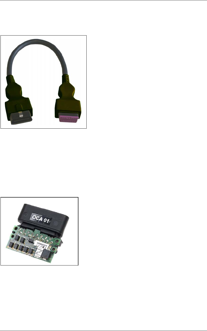
2.1.2 Order options
1. OCA-specific test adapter cable
Figure 2-2 OCA-specific test adapter cable
2. Flash memory
Depending on the model, no flash memory or memory up to 1GB can be included
3. OBD Connector Assembly (OCA)
The OCA connector is customized. Changing of the OCA in the field is possible, see
also section 4.
Figure 2-3 Customized OBD-connector OCA 01
Interfaces and display
10 of 20 BlueVCI Hardware Operating Manual
Edition 02/2007
Version V1.5
A5E00727814
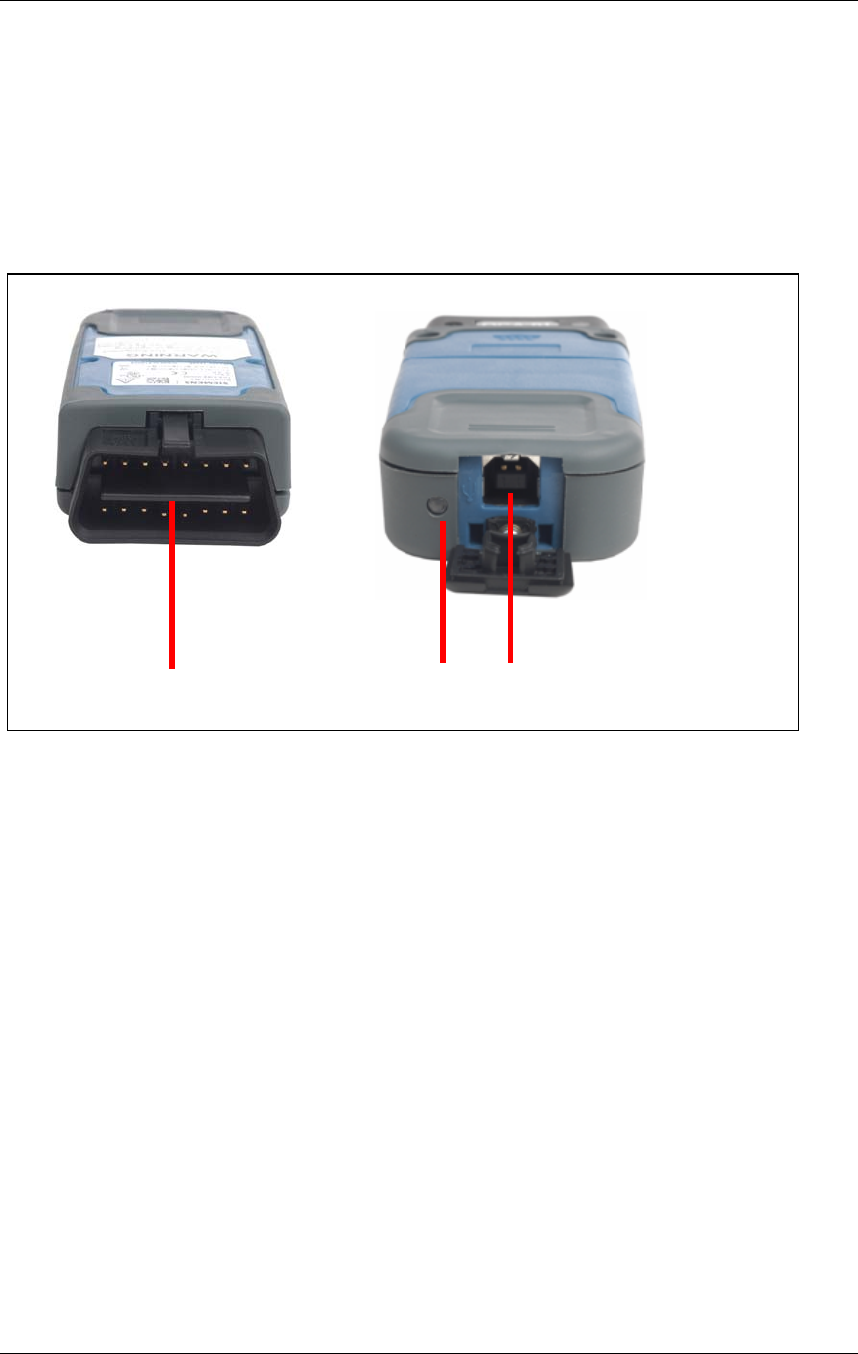
3 Interfaces and display
The BlueVCI has the following interfaces and displays (see figure 3-1):
1. Diagnostic connector (OBD)
2. USB interface, Type B
3. Three-colored LED (yellow/green/red)
1 3 2
Figure 3-1 Interfaces and display
3.1 LED display
• Green: The BlueVCI is connected to the diagnostic interface and is not
registered on a computer system.
• Green (slow flashing): The BlueVCI is registered on a computer system.
• Green (fast flashing): The BlueVCI and the computer system are transferring
data.
• Green/red (alternate flashing): Firmware update in progress.
• Red: Firmware update error.
• Red (slow flashing): The BlueVCI is overheating. If the LED is flashing, the
BlueVCI must be disconnected from the power supply. The LED then is
nonluminous.
• Yellow: Unable to start firmware.

Interfaces and display
BlueVCI Hardware Operating Manual 11 of 21
Edition 02/2007
Version V1.5
A5E00727814
3.2 OBD Connector Assembly (OCA)
A standard OCA or a manufacturer-specific OCA can be used for the vehicle
connection. The OCA is secured with the two hexagon socket screws located on the
top of the BlueVCI.
The BlueVCI can be used to measure the voltage of the following signals:
• Terminal 30, B+
• Terminal 15, ignition
• HS CAN+
• HS CAN-
• K1
• K2
• L
• J1850 PWM+ / VPW / LS CAN+
• J1850 PWM- / LS CAN-
The OBD plug interface OCA01 has the following pin assignment:
1. Terminal 15, ignition
2. SAE J1850-H, VPW or PWM or CAN LS / FT
3. ---
4. Terminal 31, B-
5. Terminal 31, B-
6. CAN_H, CAN HS
7. K line
8. ---
9. ---
10. SAE J1850_L, PWM or CAN LS / FT
11. ---
12. CAN screen
13. ---
14. CAN_L, CAN HS
15. L line, can also be used as a second K line
16. Terminal 30, B+
View of the pins
1
2 3 4 5 6
7
8
9 10 11
12
13 14 15 16
Interfaces and display
12 of 20 BlueVCI Hardware Operating Manual
Edition 02/2007
Version V1.5
A5E00727814
3.3 Communication interfaces
In addition to the USB connection, a Bluetooth or WLAN interface is available for
communication with the computer system, depending on the model of the device.
The Bluetooth interface is based on the Bluetooth standard V2.0 and has the
following properties:
• High data rate (max. 2Mbit/s)
• Pico net and scatter net
• WLAN coexistence (802.11) support (adaptive frequency hopping)
The alternative WLAN interface supports the IEEE 802.11g standard and is
backwards compatible with existing 802.11b installations.
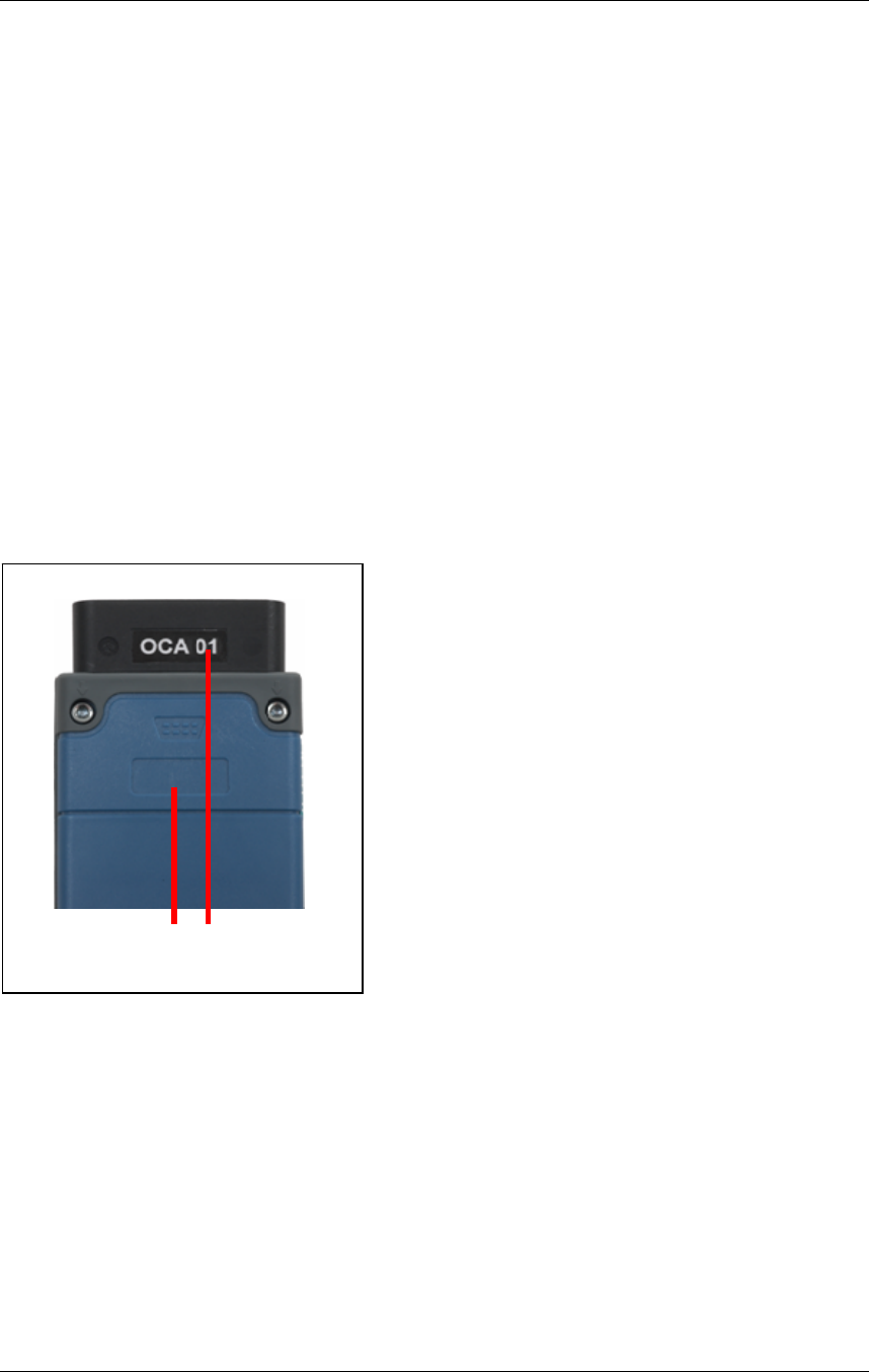
When using several BlueVCIs at the same location, the devices can be differentiated
from one another by one’s own identification. An area is available on the top of the
housing in which an own label can be attached for identification purposes.
1 2
Figure 3-2 Identification BlueVCI
1. Place for one’s own identification-code of BlueVCI
2. Identification OCA
Mechanical design
BlueVCI Hardware Operating Manual 13 of 21
Edition 02/2007
Version V1.5
A5E00727814
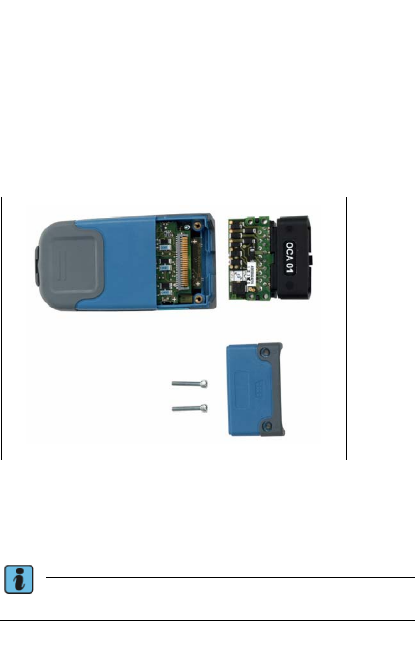
4 Mechanical design
The BlueVCI housing is made of two plastic shells that are held together by four
TORX screws. The parts of the housing made of soft plastic (soft components)
protect the device against shocks, prevent damages to surfaces and make it easier
to handle.
The housing cover is held in place by two hexagon socket screws (width 2 mm) and
can be removed to replace the OCA (see figure 4.1).
The rating plate, specifying order and serial number and rated voltage, and a safety
notice label are attached to the base of the housing.
Figure 4-1 Mechanical design and assembly
To open the BlueVCI, unscrew the two hexagon socket screws, carefully lift off the
cover and remove the OCA by lifting it slightly and pulling it forward out of the
housing.
Note
Further dismantling of the BlueVCI voids the warranty.

Function
14 of 20 BlueVCI Hardware Operating Manual
Edition 02/2007
Version V1.5
A5E00727814
5 Function
5.1 Startup
Before using the BlueVCI several software settings must be configured. That is done
by the diagnostic software. Please contact your supplier of the diagnostic software for
further information.
5.2 Operation
1. Connect the BlueVCI to the diagnostic interface on a vehicle. The LED must be
continuously lit in green.
2. If necessary, connect the USB cable. The LED blinks green. Establishing a USB
connection disconnects any existing Bluetooth or WLAN connection.
3. Perform vehicle diagnosis by using the diagnostic software installed on the
computer system.
Please find further information about operation in the documentation of your
diagnostic software supplier.

Troubleshooting and Self-Test
BlueVCI Hardware Operating Manual 15 of 21
Edition 02/2007
Version V1.5
A5E00727814
6 Troubleshooting and Self-Test
The BlueVCI was tested before leaving the factory. Carefully selected components
and performance of comprehensive quality inspections guarantee that the BlueVCI is
extremely reliable. However, if a fault should occur, refer to the information provided
in this section.
You should attempt to identify and localize the fault as accurately as possible. Follow
the solutions presented and perform all of the actions described.
6.1 Self-Test
Handling and sequence of the BlueVCI self-test are performed with the diagnostic
software application. The test adapter cable is required to do this. The power supply
is ensured by the USB connection.
6.2 Symptoms, causes and solutions
Symptom Possible cause Solution
LED continuously
lit in green. Communication link lost. Attempt to establish a different
type of communication link.
See also for specific instructions
of the diagnostic application
supplier.
LED 3 flashing red.
Communication link
interrupted.
Excess temperature in
BlueVCI during operation Disconnect the BlueVCI from the
diagnostic interface and, if
applicable the USB connection
and allow it to cool.
LED constantly lit
in yellow. Unable to start firmware. Disconnect the BlueVCI from all
connections and re-connect.
LED constantly lit
in red. Firmware update failed. Repeat firmware update.
See also for specific instructions
of the diagnostic application
supplier.
Table 6-1 Possible faults

Maintenance and support
16 of 20 BlueVCI Hardware Operating Manual
Edition 02/2007
Version V1.5
A5E00727814
7 Maintenance and support
7.1 Visual inspection
Perform a regular visual inspection of the BlueVCI. Inspect all parts for damages e.g.
breakages and dirt.
Regularly check the device, all cables and the accessories for damage.
If the housing is dirty, clean it with a lint-free moist (not wet) cloth.
7.2 Firmware update
To update the firmware, a corresponding update file must be stored on the computer
system. The update is done under the control of the diagnostic application software.
7.3 Replacing the diagnostic plug
The diagnostic plug is attached to the BlueVCI with two hexagon socket screws and
can easily be replaced in case of damage (see section 4).
Note
Further dismantling of the BlueVCI voids the warranty.

Technical data
BlueVCI Hardware Operating Manual 17 of 21
Edition 02/2007
Version V1.5
A5E00727814
8 Technical data
8.1 BlueVCI
Dimensions (W x H x D) Approx. 47 x 24 x 104 mm
Weight Approx. 95 g
Ambient requirements
Operation
Transportation and
storage
Ambient temperature 0 to +45°C
Relative humidity At max. +25°C
10 to 80%,
no condensation
Operating height -400 to +2000 m NN
Ambient temperature -20 to +60°C
Relative humidity At max. +20°C
10 to 80%,
no condensation
Mechanical protection Free fall 2 m onto hardwood surface
Electrical protection
and safety
Safety requirements:
- Workshop equipment: UL 201
- Information processing equipment:
DIN EN 60950 (VDE 0805), EN 60950, IEC 950,
UL 60950, CSA-C22.2 No. 950
- Measuring instruments: DIN EN 61010-1
(VDE 0411 Section 1), EN 61010-1, IEC 1010-1
- Degree of protection (solid body, water, humidity)
DIN EN 60529, IEC 529
- Degree of protection: IP 40
Pollution Degree II
For internal use only
Overvoltage protection category I
Power supply Vehicle electrical system or USB

Technical data
18 of 20 BlueVCI Hardware Operating Manual
Edition 02/2007
Version V1.5
A5E00727814
Supply from vehicle
electrical system
Rated voltages
Current consumption
in load range
Maximum power
consumption
Protection
8 to 18 V DC, typically 12 V DC
Max. 0.2 A at 12 V battery voltage
2.4 W
Input protected against disturbances in line with
DIN 40839 Section 1, test pulses 1 to 3, intensity IV
and test pulse 4, intensity III.
Supply via USB
Rated voltages
Maximum power
consumption
Operation on diagnostic
plug
5 V DC
< 2 W
Not possible
External interfaces,
wireless
Radio interface
- Bluetooth or
- WLAN (depending on version)
External interfaces,
wired
USB interface
Vehicle interface
1 x USB standard 1.1, type B
OBD in line with ISO 15031
Radio approvals EN 301489-1, EN 301489-17, EN 300328-2, SAR IEEE
1528, SAR EN 50371, FCC Part 15 Class A, Bluetooth,
WLAN
Displays
Status indicator
- LED (yellow / green / red)
Flash Memory None or up to 1 GB (depending on version)
8.2 USB cable
USB cable, type A-B 0.5 m standard
Contact durability > 1000

Glossary
BlueVCI Hardware Operating Manual 19 of 21
Edition 02/2007
Version V1.5
A5E00727814
9 Glossary
9.1 Abbreviations
BlueVCI Bluetooth Vehicle Communication Interface
DHCP Dynamic Host Configuration Protocol: Protocol for central
management and assignment of IP addresses
IP Internet Protocol
OBD On-board diagnosis
OCA OBD connector assembly
TCP Transmission Control Protocol
USB Universal Serial Bus
OCA OBD Connector Assembly

We checked the content of this
documentation for consistency with the
state of the device described. However,
variations cannot be ruled out and we
accept no liability for complete consis-
tency. The information in this documen-
tation is reviewed at regular intervals and
any necessary corrections are made in
subsequent editions. We are grateful for
any suggestions for improvements.
Changes to the scope of delivery are
possible in terms of the form, features
and technology. The information, figures
and descriptions in this documentation
cannot be used as a basis for any
claims. Copying, reproduction or trans-
lation, including extracts, is only per-
mitted without the written approval of
Siemens AG when it is to ensure that
appropriate documentation is enclosed
with every device. Disclosure to third
parties is not permitted. All rights under
copyright law are reserved exclusively by
Siemens AG. Subject to changes.
Copyright © Siemens AG 2007
Manufactured by:
SIEMENS AG
A&D AS AP TE SF
Siemensallee 84
D-76187 Karlsruhe
All rights reserved.