Siemens IEWSNPA1 Wireless HART Gateway User Manual IE WSN PA Link
Siemens AG Wireless HART Gateway IE WSN PA Link
UserManual.wiki
>
Siemens
>
IEWSNPA1 User Manual
Users Manual
Navigation menu
Upload a User Manual
Namespaces
Wiki Guide
HTML
PDF
Info
Views
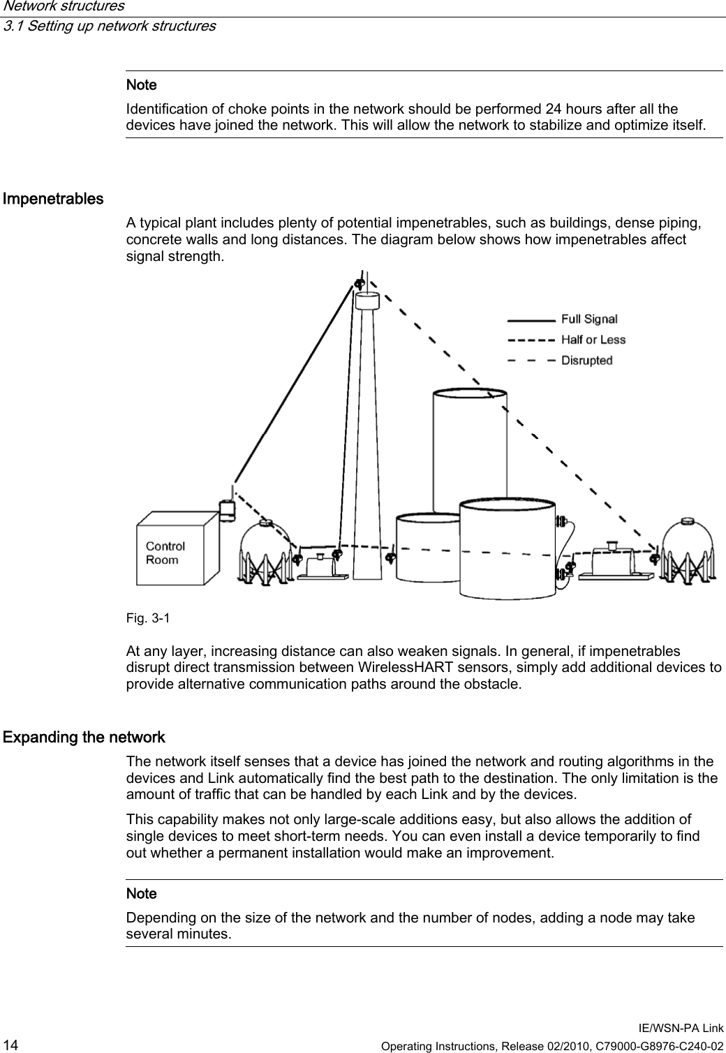
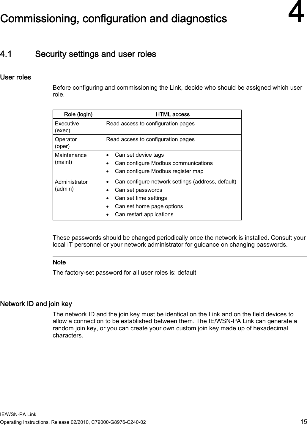
User Manual
Discussion / Help
Navigation