Siemens IEWSNPA1 Wireless HART Gateway User Manual IE WSN PA Link
Siemens AG Wireless HART Gateway IE WSN PA Link
Siemens >
Users Manual

Preface 1
Description of the product
2
Network structures
3
Commissioning,
configuration and diagnostics
4
Upkeep and maintenance
5
Technical specifications
6
Approvals
7
Biological compatibility
A
References
B
Training, Service & Support
C
SIMATIC NET
IE/WSN-PA Link
Operating Instructions
Release 02/2010
C79000-G8976-C240-02

Legal information
Warning notice system
This manual contains notices you have to observe in order to ensure your personal safety, as well as to prevent
damage to property. The notices referring to your personal safety are highlighted in the manual by a safety alert
symbol, notices referring only to property damage have no safety alert symbol. These notices shown below are
graded according to the degree of danger.
DANGER
indicates that death or severe personal injury will result if proper precautions are not taken.
WARNING
indicates that death or severe personal injury may result if proper precautions are not taken.
CAUTION
with a safety alert symbol, indicates that minor personal injury can result if proper precautions are not taken.
CAUTION
without a safety alert symbol, indicates that property damage can result if proper precautions are not taken.
NOTICE
indicates that an unintended result or situation can occur if the corresponding information is not taken into
account.
If more than one degree of danger is present, the warning notice representing the highest degree of danger will
be used. A notice warning of injury to persons with a safety alert symbol may also include a warning relating to
property damage.
Qualified Personnel
The device/system may only be set up and used in conjunction with this documentation. Commissioning and
operation of a device/system may only be performed by qualified personnel. Within the context of the safety notes
in this documentation qualified persons are defined as persons who are authorized to commission, ground and
label devices, systems and circuits in accordance with established safety practices and standards.
Proper use of Siemens products
Note the following:
WARNING
Siemens products may only be used for the applications described in the catalog and in the relevant technical
documentation. If products and components from other manufacturers are used, these must be recommended
or approved by Siemens. Proper transport, storage, installation, assembly, commissioning, operation and
maintenance are required to ensure that the products operate safely and without any problems. The permissible
ambient conditions must be adhered to. The information in the relevant documentation must be observed.
Trademarks
All names identified by ® are registered trademarks of the Siemens AG. The remaining trademarks in this
publication may be trademarks whose use by third parties for their own purposes could violate the rights of the
owner.
"Wireless HART" and "HART" are a trademark of the HART Communications Foundation.
Disclaimer of Liability
We have reviewed the contents of this publication to ensure consistency with the hardware and software
described. Since variance cannot be precluded entirely, we cannot guarantee full consistency. However, the
information in this publication is reviewed regularly and any necessary corrections are included in subsequent
editions.
Siemens AG
Industry Sector
Postfach 48 48
90026 NÜRNBERG
GERMANY
Dokumentbestellnummer: C79000-G8976-C240-01
Ⓟ02/2010
Copyright © Siemens AG 2009-2010.
Änderungen vorbehalten
IE/WSN-PA Link
Operating Instructions, Release 02/2010, C79000-G8976-C240-02 3
Table of contents
1 Preface ...................................................................................................................................................... 5
2 Description of the product.......................................................................................................................... 7
2.1 Basic functions of the link ..............................................................................................................7
2.2 Components of the product and accessories ................................................................................8
2.2.1 Components of the product............................................................................................................8
2.2.2 Accessories for attachment to Industrial Ethernet .........................................................................8
2.2.3 Accessories for the device variant with external antenna..............................................................9
2.3 Application......................................................................................................................................9
2.3.1 Connection to a wired Industrial Ethernet network ......................................................................10
2.3.2 Connection to Industrial Ethernet via IWLAN ..............................................................................10
2.4 Properties of the IE/WSN-PA Link ...............................................................................................11
2.4.1 Hardware interfaces.....................................................................................................................11
2.4.2 Housing........................................................................................................................................11
2.5 System requirements ...................................................................................................................12
2.5.1 Configuration PC..........................................................................................................................12
3 Network structures................................................................................................................................... 13
3.1 Setting up network structures ......................................................................................................13
4 Commissioning, configuration and diagnostics ........................................................................................ 15
4.1 Security settings and user roles...................................................................................................15
4.2 Commissioning the Link...............................................................................................................16
4.2.1 The configuration PC ...................................................................................................................16
4.2.2 Procedure for commissioning ......................................................................................................16
4.2.3 Establishing a connection to the Link ..........................................................................................17
4.2.4 Setting an IP address...................................................................................................................18
4.2.5 Security settings...........................................................................................................................19
4.2.6 Network data................................................................................................................................20
4.3 Configuration of the Link ..............................................................................................................21
4.3.1 Start page.....................................................................................................................................21
4.3.2 Setup > Network > Settings .........................................................................................................22
4.3.3 Setup > Network > Settings > Access Control List ......................................................................22
4.3.4 Setup > Network > Speed............................................................................................................23
4.3.5 Setup > Network > Bandwidth .....................................................................................................23
4.3.6 Setup > Network > Channels.......................................................................................................24
4.3.7 Setup > Internet Protocol .............................................................................................................24
4.3.8 Setup > Security > User Accounts...............................................................................................25
4.3.9 Setup > Security > Certificates ....................................................................................................26
4.3.10 Setup > Security > Protocols .......................................................................................................26
4.3.11 Setup > Time................................................................................................................................27
4.3.12 Setup > System Backup > Save ..................................................................................................27
4.3.13 Setup > System Backup > Restore..............................................................................................27

Table of contents
IE/WSN-PA Link
4 Operating Instructions, Release 02/2010, C79000-G8976-C240-02
4.3.14 Setup > Page Options > Point Pages ......................................................................................... 28
4.3.15 Setup > Page Options > Point Pages > Editing Custom Page................................................... 28
4.3.16 Setup > Page Options > Point Columns ..................................................................................... 29
4.3.17 Setup > Page Options > Home Pages........................................................................................ 29
4.3.18 Setup > Restart Apps.................................................................................................................. 30
4.3.19 Setup > HART > Gateway........................................................................................................... 30
4.3.20 Setup > HART > Device.............................................................................................................. 31
4.3.21 Setup > Changes ........................................................................................................................ 31
4.3.22 Setup > Modbus > Communications........................................................................................... 32
4.3.23 Setup > Modbus > Mapping........................................................................................................ 34
4.3.24 Setup > Modbus > Import/Export ................................................................................................ 37
4.3.25 Setup > Trends > Collections...................................................................................................... 37
4.3.26 Setup > Trends > Collections > Editing Custom Trend............................................................... 38
4.4 Explorer....................................................................................................................................... 39
4.5 Monitor ........................................................................................................................................ 40
4.5.1 Monitoring data points................................................................................................................. 40
4.5.2 Monitor > Custom Page .............................................................................................................. 40
4.5.3 Monitor > Quick Point Data ......................................................................................................... 40
4.5.4 Monitor > Point Data ................................................................................................................... 41
4.5.5 Monitor > Trend > Graph > Custom Trend ................................................................................. 41
4.5.6 Monitor > Trend > Report............................................................................................................ 42
4.6 Diagnostics.................................................................................................................................. 43
4.6.1 Diagnostics > Network > Overview ............................................................................................. 43
4.6.2 Diagnostics > Network > Devices ............................................................................................... 44
4.6.3 Diagnostics > Network > Join Failure ......................................................................................... 44
4.6.4 Diagnostics > Network > Invalid MICs ........................................................................................ 45
4.6.5 Diagnostics > Advanced > Network Stats................................................................................... 45
4.6.6 Diagnostics > Advanced > Modbus Stats > Serial Stats............................................................. 46
4.6.7 Diagnostics > Advanced > Modbus Stats > TCP Stats............................................................... 46
4.6.8 Diagnostics > Advanced > System Stats.................................................................................... 46
4.6.9 Diagnostics > Advanced > Client/Server .................................................................................... 47
4.7 Connecting the Link to SIMATIC S7 and SIMATIC PCS 7 ......................................................... 48
5 Upkeep and maintenance........................................................................................................................ 49
5.1 Replacing devices ....................................................................................................................... 49
5.2 Loading a new firmware version .................................................................................................49
5.3 Reset to factory settings.............................................................................................................. 50
6 Technical specifications........................................................................................................................... 51
6.1 Technical specifications of the Link ............................................................................................ 51
7 Approvals................................................................................................................................................. 53
7.1 Approvals of the Link................................................................................................................... 53
A Biological compatibility............................................................................................................................. 57
B References .............................................................................................................................................. 59
C Training, Service & Support..................................................................................................................... 61
Glossary ............................................................................................................................................................ 63
Index ................................................................................................................................................................ 67

IE/WSN-PA Link
Operating Instructions, Release 02/2010, C79000-G8976-C240-02 5
Preface 1
Validity of this manual
This manual is valid for the following versions of the IE/WSN-PA Link:
● Hardware product version 0
● Firmware version 3.8
Device variants
The following variants of the IE/WSN-PA Link are available:
Device variant Order number
IE/WSN-PA Link (with integrated antenna) 6GK1 411-6CA40-0AA0
IE/WSN-PA Link (with connection for integrated antenna *)) 6GK1 411-6CA40-0BA0
*) An external antenna is available as an accessory, see section 2.2.3.
Product name used in the manual
Note
In this document, the name "Link" is also used in place of the full product name "IE/WSN-
PA Link".
Purpose of the manual
This manual contains the information you require for commissioning, configuring and
operating the Link.
Installation and connecting up the Link is described in the Operating Instructions (compact)
that are supplied with the product.
IE/WSN-PA Link
Operating Instructions, Release 02/2010, C79000-G8976-C240-02 7
Description of the product 2
2.1 Basic functions of the link
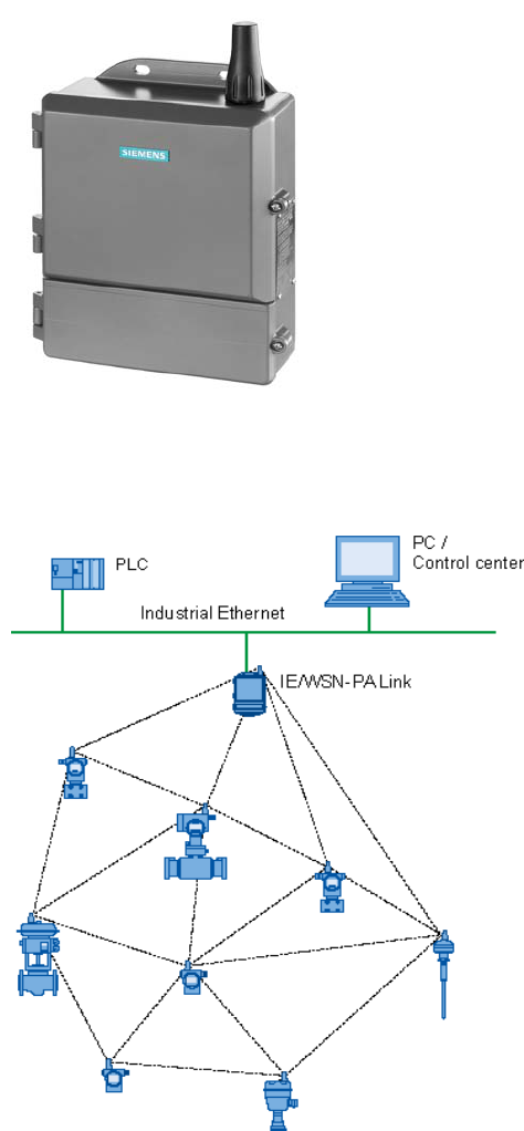
Fig. 2-1 IE/WSN-PA Link (device variant with integrated antenna)
The IE/WSN-PA Link is a gateway between a WirelessHART™ network (wireless sensor
network = WSN) and a wired local area network (LAN).
Fig. 2-2 Use of the IE/WSN-PA Link as a gateway between a WirelessHART network (WSN) and
a wired network

Description of the product
2.2 Components of the product and accessories
IE/WSN-PA Link
8 Operating Instructions, Release 02/2010, C79000-G8976-C240-02
The IE/WSN-PA Link allows a self-organizing WirelessHART network to be set up and
manages security and connectivity. The Link is the input point for data from WirelessHART
sensors. This data is converted to a format compatible with other systems. System
integration can be achieved in conjunction with an HMI system: With TCP/IP via HTTPS
browser, OPC server, Modbus TCP/IP via Ethernet or Modbus RTU via a serial connection.
The IE/WSN-PA Link provides industry leading security, scalability, and functionality. You
can customize security levels to meet plant standards via a web-based interface. This
interface also allows monitoring of points, simple trending, customized measuring point lists,
basic configuration, and security management.
The network can be expanded easily with the IE/WSN-PA Link. Simply set the network ID
and the Join key on the new device and this becomes part of the existing network.
2.2 Components of the product and accessories
2.2.1 28BComponents of the product
What the package contains
The following components are supplied with the IE/WSN-PA Link:
● IE/WSN-PA Link
● Mast fittings comprising 2 mast clamps (78 mm) and screws
● Threaded blind plugs 1/2 inch NPT for unused cable feedthroughs
● LAN cable (1 meter) for connecting a PC/laptop (for direct connection to a non-Switch
network component)
● Operating Instructions (compact) on paper
● CD with important documentation and software:
– These operating instructions for the IE/WSN-PA Link (PDF)
– Operating Instructions (compact) for the IE/WSN-PA Link (PDF)
2.2.2 29BAccessories for attachment to Industrial Ethernet
Accessories for the IE/WSN-PA Link
Suitable products are available for outdoor installation of the Ethernet cabling. The following
products are not supplied with the IE/WSN-PA Link.
● Adapter cable M12 female NPT 1/2" to RJ-45 jack, length 11 cm
Harting Electronics GmbH & Co KG
Order number 21 03 683 6420

Description of the product
2.3 Application
IE/WSN-PA Link
Operating Instructions, Release 02/2010, C79000-G8976-C240-02 9
You will find information on ordering at the following Internet address
85Hwww.harting.com -> contact -> adresse
● Ethernet SIMATIC NET IE FC standard cable GP 2x2
Order no. 6XV1 840-2AH10
The cable is not suitable for underground installation.
● M12 male connector IE FC M12 Plug PRO for assembly in the field
Order no. 6GK1 901-0DB20-6AA0
2.2.3 30BAccessories for the device variant with external antenna
Optional accessories
The following accessories for the device variant 6GK1 411-6CA40-0BA0 are not supplied
with the IE/WSN-PA Link:
● External antenna ANT792-6MN
Order number 6GK5 792-6MN00-0AA6
● Lightning protection element LP798-1N
Order number 6GK5 798-2LP00-2AA6
● Antenna cable (10 m) N-Connect male/male flexible connecting cable
Order number 6XV1 875-5AN10
● Antenna cable (1 m) N-Connect male/male flexible connecting cable
Order number 6XV1 875-5AH10
● 2.4 GHz IWLAN RCoax N-Connect male/male coupler
Order number 6GK5 798-0CP00-1AA0
2.3 Application
The Link is intended to link a WirelessHART network (WSN) to an Industrial Ethernet
network.
Data transmission of the WirelessHART sensors can be configured via the Link and the data
of the sensors can be transferred from the Link to the stations connected via Ethernet. The
WirelessHART devices can be displayed and diagnostics functions run.
The following two diagrams are typical sample configurations showing how the
IE/WSN-PA Link can be connected to a control system, an operator control and monitoring
station or, for example, to a maintenance station.
Description of the product
2.3 Application
IE/WSN-PA Link
10 Operating Instructions, Release 02/2010, C79000-G8976-C240-02
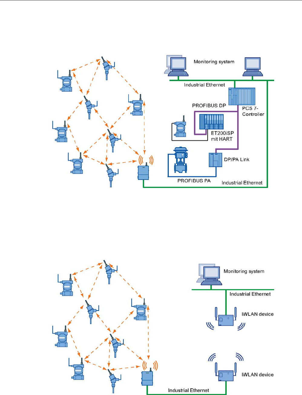
2.3.1 31BConnection to a wired Industrial Ethernet network
The following schematic shows a configuration in which the IE/WSN-PA Link is connected
via a wired Industrial Ethernet network.
Fig. 2-3 Example of a configuration of a Link with attachment to wired Industrial Ethernet
2.3.2 32BConnection to Industrial Ethernet via IWLAN
The following schematic shows a configuration in which the IE/WSN-PA Link is connected
via IWLAN to an Industrial Ethernet network. This increases the flexibility in the location of
the Link. By connecting the Link to an IWLAN node (client or access point), you can transfer
data from the WSN via WLAN.
Fig. 2-4 Example of a configuration of a Link with attachment to Industrial Ethernet via IWLAN

Description of the product
2.4 Properties of the IE/WSN-PA Link
IE/WSN-PA Link
Operating Instructions, Release 02/2010, C79000-G8976-C240-02 11
2.4 Properties of the IE/WSN-PA Link
2.4.1 33BHardware interfaces
Interfaces
● Wireless interface for connection to a WirelessHART network (WSN)
– Radio frequencies
2.4 - 2.5 GHz DSSS (Direct sequence spread spectrum technology) sliced into 16
radio-channels, based on standard IEEE 802.15.4
Continually “hop” across channels to avoid interference and increase reliability
– Antenna
Integrated omnidirectional antenna (device variant 6GK1 411-6CA40-0AA0)
Option: Remote omnidirectional antenna (installed via N-Connect female connector of
device variant 6GK1 411-6CA40-0BA0)
● Ethernet
2 LAN interfaces as RJ-45 jacks for connection to an Industrial Ethernet network
10baseT/100baseT Ethernet communication port, supports Modbus TCP/IP.
Some configuration of the field devices (communication parameters) and monitoring is
performed using Web pages generated by the IE/WSN-PA LINK.
● RS 485
2-wire communication link for Modbus multidrop connections
Transmission speed: 57.600, 38.400, 19.200, or 9.600
Protocol: Modbus RTU
2.4.2 34BHousing
Housing design
● Rugged industrial housing
The rugged housing of the Link allows field installation in any Zone 2 / Division 2 and is
NEMA 4X / IP 65 rated.
The cast aluminum housing encloses the electronics and circuitry of the Link. The front of
the enclosure has two covers:
– The upper cover
Normally the upper cover does not need to be opened.
– The lower cover
The lower cover provides access to the junction box which contains the terminals for
the power supply, and Ethernet and serial Modbus connections.

Description of the product
2.5 System requirements
IE/WSN-PA Link
12 Operating Instructions, Release 02/2010, C79000-G8976-C240-02
2.5 System requirements
2.5.1 35BConfiguration PC
System requirements for the configuration PC
For the initial configuration, a PC/laptop must meet or exceed the following criteria:
Operating system:
● Windows 2000, service pack 4
● Windows Server 2003
● Windows XP (Home or Professional), Service Pack 1 or higher.
Applications:
● A Web browser, for example
– Internet Explorer 6.0 or higher (recommended)
– Mozilla Firefox 1.5 or higher
● Adobe Acrobat 5.0 (or higher) for the Operating Instructions

IE/WSN-PA Link
Operating Instructions, Release 02/2010, C79000-G8976-C240-02 13
Network structures 3
3.1 Setting up network structures
Note
To make optimum use of the WirelessHART network, a site survey of the WSN network
under local conditions is a must.
Where possible, mount the Link or the external antenna of the Link at a location where a
connection to several WirelessHART devices is possible.
To achieve ideal illumination, we recommend that each network node should have at least
two neighbors.
Overview
This chapter discusses ways to ensure good performance and security in the WirelessHART
network. After commissioning the network, the connections should be checked and choke
points in the network eliminated. If expansions to the network become necessary, they
increase the span and reliability of the network.
This chapter lays out guidelines to increase and ensure the security of the network.
Verify connections
A good connection should have the following characteristics:
● Data reliability > 99%
● Data latency < 3 times the update rate
● Battery life > desired life span at fastest update rate. Note the information from the field
device vendor.
● The Radio Signal Strength Indication (RSSI) in the Link diagnostics is helpful. This check
is listed last because it can be misleading on its own (weak signals can still get through if
the path is stable), but it can help to identify a problems when they arise.
Choke points in the network
Next, identify choke points in the network. If messages from several devices all have to pass
through a single device on their way to the Link, this may lead to a choke point in the
available bandwidth.
This does not happen often because of the redundant communication paths in most self-
organizing networks. The solution is simply to add additional devices near the device that
represents the choke point to provide more communication paths.
Network structures
3.1 Setting up network structures
IE/WSN-PA Link
14 Operating Instructions, Release 02/2010, C79000-G8976-C240-02
Note
Identification of choke points in the network should be performed 24 hours after all the
devices have joined the network. This will allow the network to stabilize and optimize itself.
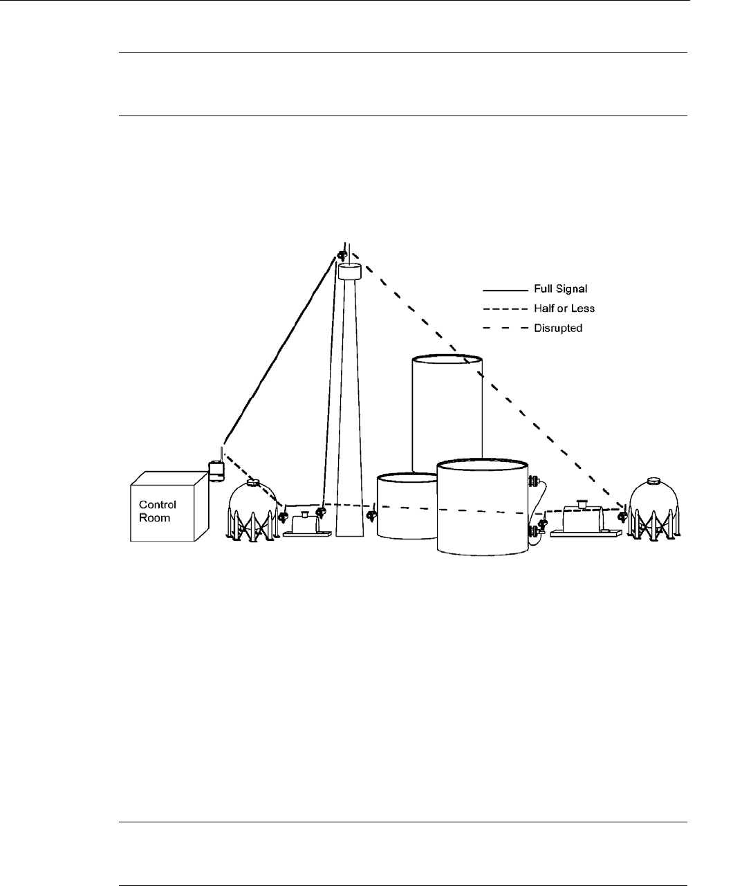
Impenetrables
A typical plant includes plenty of potential impenetrables, such as buildings, dense piping,
concrete walls and long distances. The diagram below shows how impenetrables affect
signal strength.
Fig. 3-1
At any layer, increasing distance can also weaken signals. In general, if impenetrables
disrupt direct transmission between WirelessHART sensors, simply add additional devices to
provide alternative communication paths around the obstacle.
Expanding the network
The network itself senses that a device has joined the network and routing algorithms in the
devices and Link automatically find the best path to the destination. The only limitation is the
amount of traffic that can be handled by each Link and by the devices.
This capability makes not only large-scale additions easy, but also allows the addition of
single devices to meet short-term needs. You can even install a device temporarily to find
out whether a permanent installation would make an improvement.
Note
Depending on the size of the network and the number of nodes, adding a node may take
several minutes.

IE/WSN-PA Link
Operating Instructions, Release 02/2010, C79000-G8976-C240-02 15
Commissioning, configuration and diagnostics 4
4.1 Security settings and user roles
User roles
Before configuring and commissioning the Link, decide who should be assigned which user
role.
Role (login) HTML access
Executive
(exec)
Read access to configuration pages
Operator
(oper)
Read access to configuration pages
Maintenance
(maint)
Can set device tags
Can configure Modbus communications
Can configure Modbus register map
Administrator
(admin)
Can configure network settings (address, default)
Can set passwords
Can set time settings
Can set home page options
Can restart applications
These passwords should be changed periodically once the network is installed. Consult your
local IT personnel or your network administrator for guidance on changing passwords.
Note
The factory-set password for all user roles is: default
Network ID and join key
The network ID and the join key must be identical on the Link and on the field devices to
allow a connection to be established between them. The IE/WSN-PA Link can generate a
random join key, or you can create your own custom join key made up of hexadecimal
characters.

Commissioning, configuration and diagnostics
4.2 Commissioning the Link
IE/WSN-PA Link
16 Operating Instructions, Release 02/2010, C79000-G8976-C240-02
4.2 Commissioning the Link
Note
Order of powering up
The power supply of the WirelessHART field devices should not be turned on before the
IE/WSN-PA Link is installed and working correctly. WirelessHART field devices should be
powered up in the order of their distance to the IE/WSN-PA Link starting with the nearest
device to the Link. This strategy will allow the wireless sensor network to form faster.
4.2.1 36BThe configuration PC
Connecting the configuration PC
The PC/laptop must be connected to the LAN connector P1 of the IE/WSN-PA Link using a
crossover cable.
You will find the other requirements in section 187H2.5.1.
CAUTION
Under no circumstances, use the covered "POE" connector on the Link, this can cause damage to the
PC/laptop.
4.2.2 37BProcedure for commissioning
Follow the steps below to commission the IE/WSN-PA Link:
CAUTION
If you use a PC/laptop from a different network, you should note the current IP address and other
settings carefully so that the PC/laptop can be assigned to its original network again after configuring
the IE/WSN-PA Link.
Note
When commissioning the Link, remember that other wireless systems in the 2.4 gigahertz
band be affected by interference or may cause interference.
You will find a list of WHART and WLAN channels in section 188H4.3.6.
To be able to reach the IE/WSN-PA Link using the standard IP address, you will first need to
adapt the network address of the PC/laptop.

Commissioning, configuration and diagnostics
4.2 Commissioning the Link
IE/WSN-PA Link
Operating Instructions, Release 02/2010, C79000-G8976-C240-02 17
1. Select the menu command Start > Settings (> Control Panel) > Network and Dial-up
Connections.
The "Network connections" dialog opens.
2. Select the "Local Area Connection" entry.
3. Select "Properties" in the shortcut menu.
The "Properties of Local Area Network" dialog opens at the "General" tab.
4. In the "This connection uses the following items" box, select the entry "Internet Protocol
(TCP/IP)".
5. Click the "Properties" button.
The "Properties of Internet protocol (TCP/IP)" dialog opens.
6. Select the "Use following IP address" option.
7. In the "IP address" input box, enter an IP address for your configuration PC that differs
from the factory-set IP address of the Link, for example 192.168.1.12.
8. Enter the value 255.255.255.0 in the "Subnet mask" input box.
9. Click the "OK" button.
10. Close the "Network and Dial-up Connections" dialog.
Your PC/laptop can now be reached using the IP address set above.
4.2.3 38BEstablishing a connection to the Link
1. Start your Web browser.
2. Select the "Tools" > "Internet Options..." menu command.
The "Internet Options" dialog opens.
3. Select the "Connections" tab.
4. In the "Local Area Network (LAN) Settings" area, click the "LAN Settings...) button.
The "Local Area Network (LAN) Settings" dialog opens.
5. If selected, deselect the following options:
– "Automatically detect settings"
– "Use automatic configuration script"
– "Use a proxy server for your LAN"
These settings will not apply to dial-up of VPN connections.
6. Click the "OK" button.
7. To start the Web interface of your IE/WSN-PA Link, enter the following in the address
line:
86Hhttps://192.168.1.10 (IP address set in the factory for the P1 LAN interface of the Link)
or
87Hhttps://192.168.2.10 (IP address set in the factory for the P2 LAN interface of the Link)
Commissioning, configuration and diagnostics
4.2 Commissioning the Link
IE/WSN-PA Link
18 Operating Instructions, Release 02/2010, C79000-G8976-C240-02
8. Enter the following in the "Connect to IE/WSN-PA Link" dialog:
– User name (login): admin
– Password: default
See also section 189H4.2.5 "190HSecurity settings".
9. Click the "Yes" button in the "Security Alert" dialog.
The start page of the Link opens (for screenshot, see section 191H4.3.1).
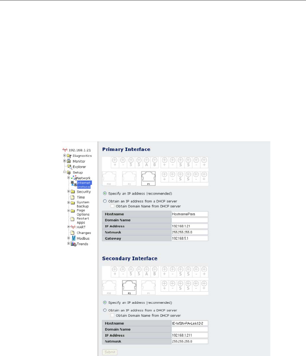
4.2.4 39BSetting an IP address
1. Select the "Setup" > "Internet Protocol" menu command.
The "Internet Protocol Address" dialog opens.
2. Enter the required IP address in the "IP Address" box or if you use a DHCP server ,
enable the option "Obtain an IP address from a DHCP server" and enter a host name in
the "Host name" box.
3. Click the "Submit" button to save the changes.
Commissioning, configuration and diagnostics
4.2 Commissioning the Link
IE/WSN-PA Link
Operating Instructions, Release 02/2010, C79000-G8976-C240-02 19
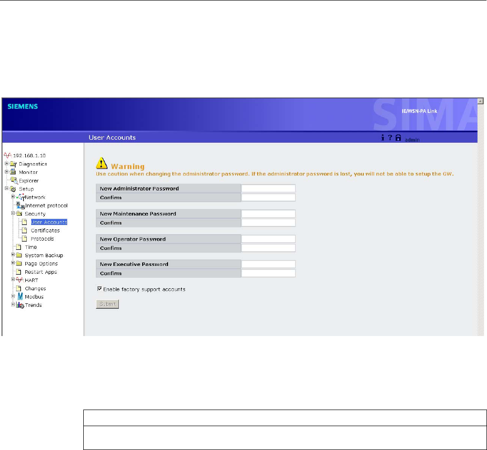
4.2.5 40BSecurity settings
1. Select the "Setup" > "Security" > "User Accounts" menu command.
The "User Accounts" dialog opens.
2. Modify the administrator password
Enter a new password in the "New Administrator Password" and "Confirm" input boxes.
For the factory-set passwords, refer to section 192H4.1.
CAUTION
Use caution when changing the administrator password. If the administrator password is lost, you will
not be able to operate the IE/WSN-PA Link from the administrator role.
3. Click the "Submit" button.
Commissioning, configuration and diagnostics
4.2 Commissioning the Link
IE/WSN-PA Link
20 Operating Instructions, Release 02/2010, C79000-G8976-C240-02
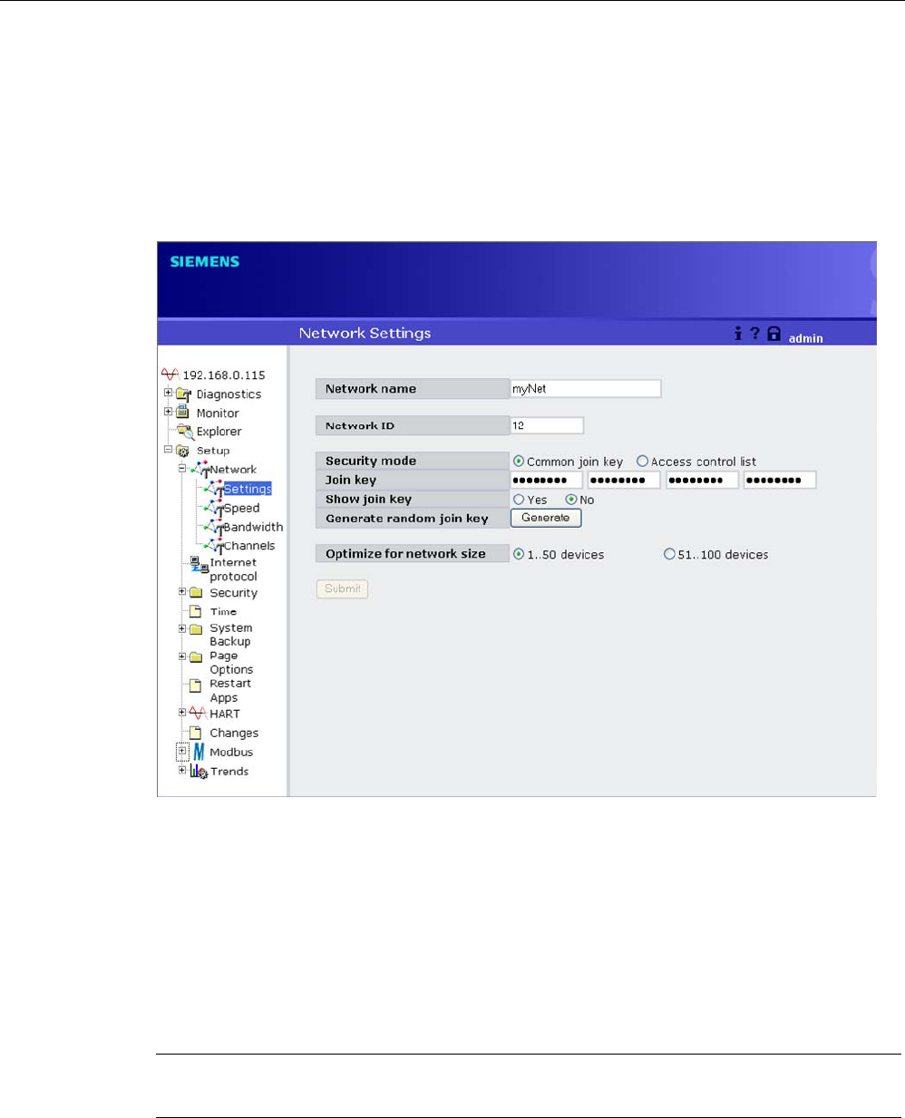
4.2.6 41BNetwork data
1. Select the "Setup" > "Network" > "Settings" menu command.
The "Network Settings" dialog opens.
2. Enter the network ID of your WirelessHART network in the "Network ID" input box.
Numbers in the range 0…65 535 are permitted.
3. Enter the join key of your WirelessHART network in the "Join key" input box as a
hexadecimal number.
4. Click the "Submit" button.
5. Select the "Setup" > "Restart Apps" menu command.
This completes the initial commissioning of the IE/WSN-PA Link. You can remove the
PC/laptop and restore the original settings on the PC/laptop.
Note
You will find a detailed description of all the configuration functions of the Link in section 193H4.3.
Commissioning, configuration and diagnostics
4.3 Configuration of the Link
IE/WSN-PA Link
Operating Instructions, Release 02/2010, C79000-G8976-C240-02 21
4.3 Configuration of the Link
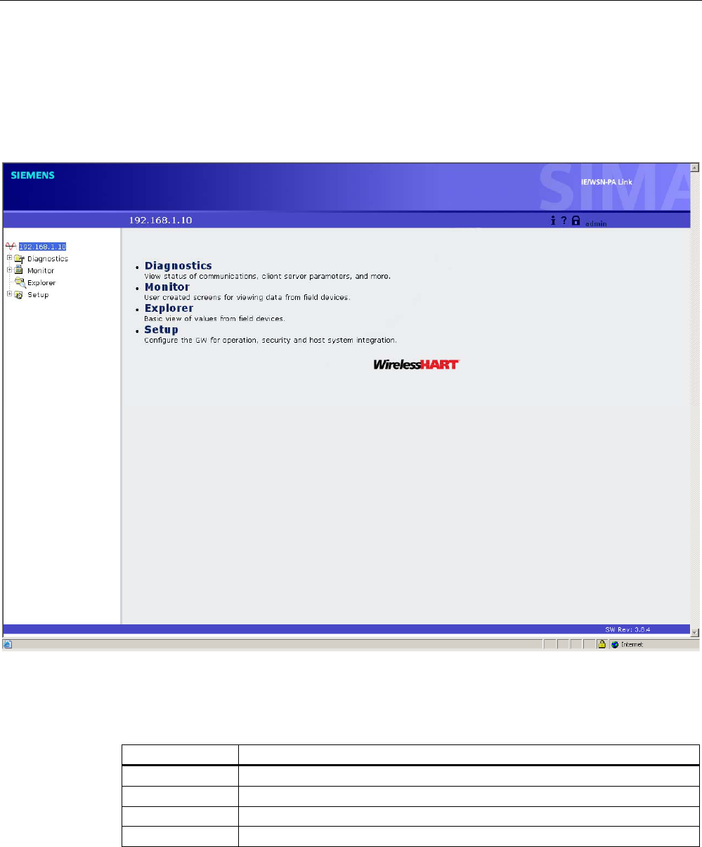
4.3.1 42BStart page
Fig. 4-1 Start page of the Web-based configuration tool of the Link
The HTML pages of the Link have the following basic structure:
Entry Description
Diagnostics Check the communication status, client/server parameters etc.
Monitor Customized Web pages for monitoring the data of the field devices
Explorer View of the values of the field devices
Setup Configure the Link for operation, security and host system integration.
From the navigation area on the left, you can expand the structure of the HTML pages and
jump to specific pages by clicking with the mouse.

Commissioning, configuration and diagnostics
4.3 Configuration of the Link
IE/WSN-PA Link
22 Operating Instructions, Release 02/2010, C79000-G8976-C240-02
4.3.2 43BSetup > Network > Settings
You will find a screenshot of the page in section 194H4.2.6.
CAUTION
It is not advisable to change the network ID while a network is in operation. This will reset
the network and cause it to need to reform.
Entry Description
Network name Network name (plain text)
Network ID Network ID
Security mode Select either a common join key for all network nodes or individual join keys that
you can specify in the access control list.
If you select the "Access control list" option, the next page, "Access control list"
opens in which individual join keys will be applied to each device (see below).
Common join key With this security mode, all the devices in the WirelessHART network use the
same join key
Access control list Under this security mode, the Link maintains an access control list and each
device has a separate and unique join key
Show join key Allows the user to see the current common join key for the WirelessHART
network
Generate random
join key
Causes the Link to generate a new common join key. Any change is passed on
to all WirelessHART devices currently connected to the WirelessHART network.
Optimize for
network size
Optimizes the Link for communicating with smaller (1-50 devices) networks or
larger (51-100 devices) networks.
Submit Accepts all changes (highlighted in yellow).
4.3.3 44BSetup > Network > Settings > Access Control List
Parameter settings for the access control list
On this page, you make the parameter settings for the access control list with which you
allow individual WSN devices access to your WirelessHART network.
Entry Description
Device ID The unique device ID of the device
Device name The long HART tag of the device
Generate new join
key
Generates a new unique join key for the device
Online Indicates the device is communicating on the WirelessHART network.
Common join key Indicates the device is using a common join key.
Default join key Indicates the device is using the default join key.
<<First Navigates to the first page of this table.

Commissioning, configuration and diagnostics
4.3 Configuration of the Link
IE/WSN-PA Link
Operating Instructions, Release 02/2010, C79000-G8976-C240-02 23
Entry Description
<<Previous Navigates to the previous page of this table.
Search Finds the next occurrence of the characters entered into this field.
Next>> Navigates to the next page of this table.
Last>> Navigates to the last page of this table.
New entry Creates a new entry in this table.
Show join failure Go to the page "Diagnostics" > "Network" > "Join failures".
Add entries for join
failure
Creates new entries in this table and populates them with the current join
failures.
Delete selected Removes the selected entry from this table.
Check generate
key for selected
Checks the Generate New Join Key box for all selected entries.
Select all Selects all table entries.
Select none Deselects all table entries.
Select online Selects all online devices in this table.
Select new join
key recommended
Selects all devices with a common join key or a default join key.
Submit Accepts all changes (highlighted in yellow).
4.3.4 45BSetup > Network > Speed
Entry Description
Active advertising Shows whether active advertising is enabled or disabled. If active advertising is
enabled, the WirelessHART network increases the sending of advertising
frames to accelerate the joining of field devices in the network. Active
advertising is automatically activated for 30 minutes when the Link is powered
up.
Duration (minutes) Determines how long (in minutes) active advertising will be enabled.
Activate Causes the WirelessHART network to enter active advertising mode
Fast pipe Shows whether fast pipe is activated or deactivated. Fast pipe creates a
dedicated channel for communication to the selected device. Used for large data
transfers.
Device selector Selects a device to establish fast pipe.
Activate Causes the Link to establish a fast pipe connection with the selected device.
4.3.5 46BSetup > Network > Bandwidth
Entry Description
Analyze again Analyzes the WirelessHART network to determine if any devices require more
bandwidth.

Commissioning, configuration and diagnostics
4.3 Configuration of the Link
IE/WSN-PA Link
24 Operating Instructions, Release 02/2010, C79000-G8976-C240-02
4.3.6 47BSetup > Network > Channels
Channel activation
On this page, you can enable or disable the individual wireless channels.
Entry Description
Enable Select the option (check mark) to enable the channel.
Channel Number of the channel
Frequency (GHz) Frequency of the channel in GHz
Clear channel
access
assessment (CCA)
WirelessHART function that automatically enables/disables individual channels
depending on the wireless load on channels. It is recommended that this option
is set to "no".
It may be useful to disable channels if there are other wireless nodes in your plant that do
not belong to your WirelessHART network (for example IWLAN nodes) and with which
overlaps or interference may occur on certain channels.
Overlapping frequency range in WLAN and WHART systems in the 2.4 GHz band:
WLAN channel
802.11b/g
WHART channel
802.15.4
1 11-16
6 15-20
7 16-21
11 20-25
13 21-25
4.3.7 48BSetup > Internet Protocol
Ethernet network configuration
Note
The best protection against accidental errors during assignment of the IP address is not to
change the IP addresses of Ethernet port P1 and P2 at the same time. If P1 has the wrong
setting, you can still access the device via P2.
You will find a screenshot of the page in section 195H4.2.4.

Commissioning, configuration and diagnostics
4.3 Configuration of the Link
IE/WSN-PA Link
Operating Instructions, Release 02/2010, C79000-G8976-C240-02 25
Entry Description
Primary interface Refers to Ethernet port P1
Secondary
interface
Refers to Ethernet port P2
Specify an IP
address
The interface is assigned a fixed IP address.
Obtain an IP
address from a
DHCP server
The interface obtains an IP address assigned by a DHCP server.
Obtain domain
name from DHCP
server
The interface obtains a domain name assigned by a DHCP server.
Hostname Hostname for the Link.
Domain name Domain name
IP Address IP address set by the user for the associated interface.
Netmask Netmask set by the user for the associated interface.
Gateway Gateway set by the user for the associated interface (not to be confused with the
IE/WSN-PA Link)
Submit Accepts all changes (highlighted in yellow).
4.3.8 49BSetup > Security > User Accounts
The basic security settings and user roles are described in section 196H4.1. Below, you will find
additional information.
Note
It is recommended that passwords be changed for security purposes. Consult your network
administrator for guidelines on setting passwords.
Entry Description
New administrator
password
Box for entering a new administrator password
New maintenance
password
Box for entering a new maintenance password
New operator
password
Box for entering a new operator password
New executive
password
Box for entering a new executive password
Confirm Box to confirm the new password for each user role.
Enable factory
support accounts
Enabling this option allows trained service personnel to upgrade firmware and
run extra diagnostics functions.
Note the following information.
Submit Accepts all changes (highlighted in yellow).

Commissioning, configuration and diagnostics
4.3 Configuration of the Link
IE/WSN-PA Link
26 Operating Instructions, Release 02/2010, C79000-G8976-C240-02
Note
The "Enable factory support accounts" option is not enabled as default. A new firmware
version can only loaded if the option was enabled previously.
Note that changing the setting of "Enable factory support accounts" only takes effect after
restarting the application and that the option is automatically disabled again after a cold
restart on the Link (cycling power OFF ON).
4.3.9 50BSetup > Security > Certificates
Entry Description
Import GW
certificate into
webrowser
Sends security certificates of the Link to the Web browser.
Rebuild GW
certificates
Rebuilds the security certificates for the Link.
4.3.10 51BSetup > Security > Protocols
Entry Description
Enable Enables associated communication protocol and opens the specified TCP / UDP
port.
Protocol Type of Ethernet communication protocol
TCP port The TCP port used by the associated communication protocol
UDP port The UDP port used by the associated communication protocol
HTTP Ethernet communication protocol used for the Link's Web-based user interface.
HTTPS SSL-compliant Ethernet communication protocol used for the Link's Web-based
user interface.
Modbus TCP Ethernet communication protocol used for communication with Modbus TCP-
compliant hosts.
Modbus TCP
secure
SSL-compliant Ethernet communication protocol used for communication with
Modbus TCP-compliant hosts.
Submit Accepts all changes (highlighted in yellow).
Defaults Restores the default protocols and port numbers.

Commissioning, configuration and diagnostics
4.3 Configuration of the Link
IE/WSN-PA Link
Operating Instructions, Release 02/2010, C79000-G8976-C240-02 27
4.3.11 52BSetup > Time
WARNING
Note that setting the date or time causes a restart on the Link and therefore a temporary
loss of communication.
Entry Description
Your PC’s time The time used by the PC client
GW time The time currently used by the Link.
Difference The difference between the PC client time and the Link time
Method used to
set time
Selects what method to use when setting the Link time.
Network Time
Protocol (NTP)
Uses NTP time.
Set with PC time Uses the current PC client time.
Manual entry Uses the Date and Time fields.
Date (mm/dd/yy) Manually enter the date (mm/dd/yy)
Time (hh:mm:ss) Manually enter the time (hh:mm:ss)
Submit Accepts all changes (highlighted in yellow).
Take note of the following warning notice.
4.3.12 53BSetup > System Backup > Save
Entry Description
Include diagnostic
information in
system backup
Saves Link diagnostic log information with the system backup file.
Save
Configuration
Collects the Link configuration data and creates a system backup file. This
system backup file is saved on the PC client as a zip file (*.zip).
4.3.13 54BSetup > System Backup > Restore
CAUTION
Note that resetting to factory defaults deletes the entire configuration of the Link.
Entry Description
Browse… Opens a navigation window to locate a system backup file (zip file) on the PC
client.
Upload
configuration
Uploads the configuration of the selected system backup file to the Link.
Reset defaults Returns the Link to default factory configuration.
See also section 197H5.3.

Commissioning, configuration and diagnostics
4.3 Configuration of the Link
IE/WSN-PA Link
28 Operating Instructions, Release 02/2010, C79000-G8976-C240-02
4.3.14 55BSetup > Page Options > Point Pages
Entry Description
Name Name of the custom point page (user specified)
Order Order in which custom point pages appear in the "Monitor" section of the
navigation menu
UP Moves the associated point page up in the navigation order.
Down Moves the associated point page down in the navigation order.
Actions The actions you can perform on the associated point page.
Edit Navigates to the configuration of the associated page and allows the user to
make changes.
Delete Deletes the associated page.
Go to Navigates to the associated point page in the web interface.
New Starts a new custom point page.
Submit Accepts all changes (highlighted in yellow).
4.3.15 56BSetup > Page Options > Point Pages > Editing Custom Page
Entry Description
Page name Name of this custom point page as it will appear in the "Monitor" navigation
menu.
Point name Identifies the data point to display. Data point names have the following syntax:
(longHARTTag.parameter).
Name Name set by the user for the data point.
Description Description of the data point entered by the user.
Order The order in which the associated data point appears on the custom point page.
Up Moves the associated data point up in the order.
Down Moves the associated data point down in the order.
<<First Navigates to the first page of this table.
<<Previous Navigates to the previous page of this table.
Search Finds the next occurrence of the characters entered into this field.
Next>> Navigates to the next page of this table.
Last>> Navigates to the last page of this table.
Delete selected Removes the selected entry from this table.
Select all Selects all table entries.
Select none Deselects all table entries.
Select errors Selects all table entries with error messages.
Submit Accepts all changes (highlighted in yellow).

Commissioning, configuration and diagnostics
4.3 Configuration of the Link
IE/WSN-PA Link
Operating Instructions, Release 02/2010, C79000-G8976-C240-02 29
4.3.16 57BSetup > Page Options > Point Columns
Entry Description
Device Indicates whether or not the "Device" column appears as default in the point
pages.
Device desc Indicates whether or not the "Device desc" column appears as default in the
point pages.
Parameter Indicates whether or not the "Parameter" column appears as default in the point
pages.
Point Indicates whether or not the "Point" column appears as default in the point
pages.
Name Indicates whether or not the "Name" column appears as default in the point
pages.
Description Indicates whether or not the "Description" column appears as default in the point
pages.
Value Indicates whether or not the "Value" column appears as default in the point
pages.
Units Indicates whether or not the "Units" column appears as default in the point
pages.
Status description Indicates whether or not the "Status description" column appears as default in
the point pages.
Status icon Indicates whether or not the "Status icon" column appears as default in the point
pages.
Submit Accepts all changes (highlighted in yellow).
4.3.17 58BSetup > Page Options > Home Pages
Entry Description
GW menu
overview
Indicates that the Link menu overview is the default home page when logging
into the Link Web-based user interface.
Custom page Indicates that the Custom Point page is the default home page when logging
into the Link Web-based user interface.
Point monitor Indicates that the "Point Monitor" page is the default home page when logging
into the Link Web-based user interface.
HART status Indicates that the HART Status page is the default home page when logging into
the Link Web-based user interface.
Quick point data Indicates that the Quick Point Data page is the default home page when logging
into the Link Web-based user interface.
Network status Indicates that the "Network status" page is the default home page when logging
into the Link Web-based user interface.
Submit Accepts all changes (highlighted in yellow).

Commissioning, configuration and diagnostics
4.3 Configuration of the Link
IE/WSN-PA Link
30 Operating Instructions, Release 02/2010, C79000-G8976-C240-02
4.3.18 59BSetup > Restart Apps
Entry Description
Restart Software reset. This is required for some configuration changes to take affect. A
physical power cycle may erase configuration changes before they take affect.
Yes The application is restarted immediately.
No Delays the restart. Configuration changes are first saved.
● Application software:
Software for the web user interface, program manager, operating system, etc.
● Suspend Gateway operations:
The Link will temporarily be inaccessible via the Web-based user interface. It will stop
reporting Modbus or OPC values or collecting trend data.
4.3.19 60BSetup > HART > Gateway
Entry Description
Use Internet
protocol host
name for gateway
name
Uses the hostname field under the Internet protocol page to replace the Link
name. This is a one time action that happens when the box is checked. Further
hostname changes will not be reflected on this page.
Gateway name Long HART tag for the Link
HART master type Indicates whether the Link is communicating as the HART primary or secondary
master. Most host systems operate as a secondary master and leave primary
master status to a handheld device.
Primary The Link will have priority over a secondary master when outputting commands
to WirelessHART field devices.
Secondary Commands from the Link to a WirelessHART device have lower priority than
those of a primary master.
Network retry
count
Number of times the Link will attempt to resend a message when it does not get
a confirmation.
Submit Accepts all changes (highlighted in yellow).

Commissioning, configuration and diagnostics
4.3 Configuration of the Link
IE/WSN-PA Link
Operating Instructions, Release 02/2010, C79000-G8976-C240-02 31
4.3.20 61BSetup > HART > Device
Note
If there is a change, in particular a reduction, in the Burst Rate, you will need to analyze the
bandwidth, see "198HSetup > Network > Bandwidth" in section 199H4.3.5.
Note the information from the field device vendor when you set the burst rate.
Entry Description
Device ID Device ID of the field device
HART tag Configures the long HART tag (32 characters).
Short tag Configures the HART tag (8 characters).
Descriptor Configures the description.
Units Configures the units.
Burst rate Configures the interval in which the WirelessHART field device transmits its
measurement data to the Link. Some devices burst multiple messages and at
different rates.
Setting options:
In the seconds range: 4, 8, 16, 32
In the minutes range: In the format "hh:mm:ss" up to a maximum of 60
minutes
Note the information from the field device vendor when you set the burst
rate.
Delete Removes the WirelessHART field device from the WirelessHART network.
% Range Percentage of user-defined range assigned to the HART primary variable.
Edit Configures the lower range limit and upper range limit.
<<First Navigates to the first page of this table.
<<Previous Navigates to the previous page of this table.
Search Finds the next occurrence of the characters entered into this field.
Next>> Navigates to the next page of this table.
Last>> Navigates to the last page of this table.
Submit Accepts all changes (highlighted in yellow).
4.3.21 62BSetup > Changes
Entry Description
Description Description of the changes adopted.
From Initial value
To Final value
Requested Time stamp of the implementation of the change
Status Indicates if the change has been successful, is in process, or has failed.

Commissioning, configuration and diagnostics
4.3 Configuration of the Link
IE/WSN-PA Link
32 Operating Instructions, Release 02/2010, C79000-G8976-C240-02
4.3.22 63BSetup > Modbus > Communications
Make the settings for IE/WSN-PA Link Modbus communication suitable for the Modbus
settings of the host.
Note
Modbus connections will fail if they are not configured identically on the host and the
IE/WSN-PA Link.
Default register addressing
The Link saves data in four separate tables. Two tables are for discrete parameters and two
are for numeric parameters. Each table contains up to 9 999 values. The discrete
parameters are saved in one-bit registers and numeric parameters are saved in 16-bit
registers.
Register description Register type Register number Address area of the
internal data table
Discrete output values -
coils
Read - write 1 – 9999 0x0000 to 0x270E
Discrete input values -
contact
Read only 10 001 – 19 999 0x0000 to 0x270E
Analog input Read only 30 001 – 39 999 0x0000 to 0x270E
Analog output - hold Read - write 40 001 – 49 999 0x0000 to 0x270E
Access to data types
Discrete data is stored in one-bit registers. If the read or write request does not contain 16
registers, the response is returned as a 16-bit value left justified.
Analog data is returned either as an integer in 16-bit registers or as a floating-point value
depending on the configuration of the Link. If floating-point representation is selected, each
floating-point value is returned as 2 linked registers that together produce a floating-point
value with single accuracy.
The following example shows the values in the client display when the holding register
40001 has the following value:
Analog value = -100.234
IEEE equivalent = 0xC2 0xC8 0x77 0xCF
Register values: (40 001) C2C8
(40 002) 77CF

Commissioning, configuration and diagnostics
4.3 Configuration of the Link
IE/WSN-PA Link
Operating Instructions, Release 02/2010, C79000-G8976-C240-02 33
Setting options
Entry Description
One Modbus
address
Selects a single Modbus RTU slave address to be used.
Multiple Modbus
address
Allows multiple Modbus RTU slave addresses to be used. These addresses are
configured per point in the Modbus mapping page.
Modbus TCP port The TCP port used to access Modbus TCP data directly from the Link.
Baud rate Communication speed for Modbus RTU.
Parity Selects the parity bits for Modbus RTU messages.
Stop bits Sets the number of stop bits for Modbus RTU messages.
Response delay
time (ms)
After receiving a request, the Link will wait this long before it sends a response.
Unmapped
register read
response?
The response the Link returns if no data points are mapped to the requested
register.
Floating point
representation
Modbus data format
Float Floating point number in two 16 bit Modbus registers.
Round Rounded integer in one 16 bit Modbus register. If measured value = 2711.97,
the rounded value = 2712.
Scale Scaled integer in one 16 bit Modbus register.
The Link uses the equation y = Ax - (B - 32768).
y = scaled integer returned by the Link, A = gain, x = measured value, B = offset.
Use swapped
floating point
format?
Reverses which significant register is used in a floating point representation.
Incorporate
value’s associated
status as error?
If the HART variable status indicates a critical failure, it will be reported through
the Modbus register.
Value reported for
error (floating
point)
Chooses what value is reported if the value’s associated status indicates a
critical failure. Only used if the Link is using floating-point representation.
NaN Not a number is reported if the value’s associated status indicates a critical
failure.
+Inf Positive infinity is reported if the value’s associated status indicates a critical
failure.
-Inf Negative infinity is reported if the value’s associated status indicates a critical
failure.
Other User-defined value is reported if the value’s associated status indicates a critical
failure.
Value reported for
error (rounded or
native integer)
User-defined value is reported if the value’s associated status indicates a critical
failure. Only used if the Link is using rounded or scaled representation.
Scaled floating
point maximum
integer value
Highest integer proportional to the measured value. Default = 65534. This is
generally the highest integer value accepted by the host system.
Use global scale
gain and offset
Determines whether scaled integers use the global scale gain and offset or
unique gain and offsets for each measured value.

Commissioning, configuration and diagnostics
4.3 Configuration of the Link
IE/WSN-PA Link
34 Operating Instructions, Release 02/2010, C79000-G8976-C240-02
Entry Description
Global scale gain Gain used by all measured values for scaled integers. The Link uses the
equation y = Ax - (B - 32768).
y = scaled integer returned by the Link, A = global scale gain, x = measured
value, B = global scale offset.
Global scale offset Offset used by all measured values for scaled integers. The Link uses the
equation y = Ax - (B - 32768).
y = scaled integer returned by the Link, A = global scale gain, x = measured
value, B = global scale offset.
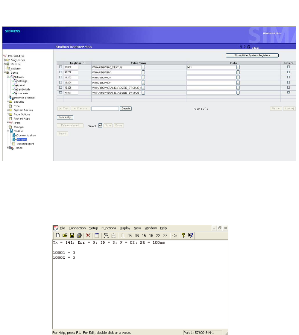
4.3.23 64BSetup > Modbus > Mapping
Configuring the Modbus mapping of status and process values
The following paragraphs explain the mapping of parameters to Modbus registers. Examples
illustrate the mapping of device status values as integer registers or as discrete registers and
the mapping of process and status values is described.
Device tags for Modbus mapping
The Link provides numerous parameters for mapping to Modbus RTU/TCP and OPC. Both
the OPC interface used for mapping and the Modbus interface contain only some of the data
points used most frequently to accelerate the user interface.
Mapping the additional device status and standardized status to Modbus registers
The additional and the standardized status of a device can be mapped to Modbus registers
in two ways. On the one hand, you can map to standard integer analog input registers. On
the other, you can map the individual bits to the relevant bytes of registers for discrete
inputs.
The parameter tags for these bits are ADDITIONAL_STATUS_0 –
ADDITIONAL_STATUS_N, where N depends on the number of status bytes supported by
the device and on STANDARDIZED_STATUS_0 – STANDARDIZED_STATUS_3.
Other status tags such as EXTENDED_STATUS (Maintenance required, Device variable
alert) and STATUS_CODE (Device malfunction, Cold start) are also available.
The bit masks required to map individual status bits to discrete Modbus registers can be
found in the "HART Common Tables" specification or in the documentation of the particular
field device.
The standard parameter mapping "DEVICE_TAG.PARAMETER" is used for the Link. For
this reason, the device tag must first be specified before correct register mapping is possible.
When mapping discrete registers, the "State" field (see Fig. 200H4-2) is also used to enter the bit
mask that is applied to the parameter and that generates the discrete value. The "Invert" field
(see Fig. 201H4-2) is used to invert the bit (conversion 0 → 1 and 1 → 0), as may be required by
the logic of the user program.
Commissioning, configuration and diagnostics
4.3 Configuration of the Link
IE/WSN-PA Link
Operating Instructions, Release 02/2010, C79000-G8976-C240-02 35
Fig. 4-2 Status mapped to an analog input
In the example of Fig. 202H4-2, bit 0 of STANDARDIZED_STATUS_0 is mapped to a discrete
register. This corresponds to the bit for "simulation active" of STANDARDIZED_STATUS_0.
Other single status bits can be mapped to registers for discrete inputs in the same way.
Fig. 203H4-3 shows an example of a Modbus client that reads the discrete inputs of the
"STANDARDIZED_STATUS_0" status (simulation active).
Fig. 4-3 Example of a Modbus client that reads a discrete input
Dynamic device variables and device status
The dynamic variables and the status of a device can also be mapped to Modbus registers.
Here, the status of the dynamic variables can be mapped to an analog input register or to an
analog holding register. The floating-point value of the dynamic variables can either be
mapped as a floating-point value to two analog holding registers at the same time or using
Commissioning, configuration and diagnostics
4.3 Configuration of the Link
IE/WSN-PA Link
36 Operating Instructions, Release 02/2010, C79000-G8976-C240-02
scaling of the register to a single analog holding register. There is also an option of mapping
the variable status mixed with the floating-point values or separate from them to another
register section such as the registers for analog inputs.
You will find an example of this in Fig. 204H4-2. This option allows maximum flexibility for the
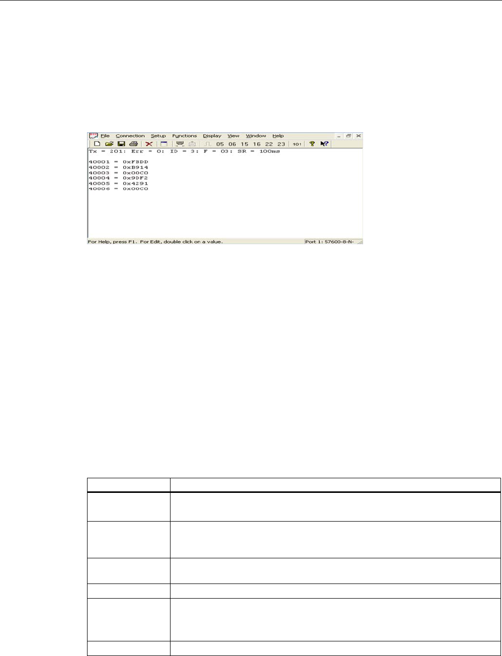
different register mappings of host systems. Fig. 205H4-4 shows an example of a Modbus RTU
client, that first reads out a mixed register map of floating-point values of a dynamic variable
followed by the status value etc.
Fig. 4-4 Example of a Modbus client that reads the variables "PV" and "PV_STATUS"
Here, the standard parameter mapping "DEVICE_TAG.PARAMETER" of the Link is used.
For this reason, the device tag must first be specified before correct register mapping is
possible.
The default dynamic variables for floating-point values are PV, SV, TV and QV. The device
variables can, however, also be mapped according to the variable number. These are
followed by the status values as PV_STATUS, SV_STATUS, TV_STATUS and
QV_STATUS. These values are unsigned single byte values and they must be mapped to a
single analog input register or a single analog holding register.
Setting options
On this page, Modbus Registers can be mapped to the measurement points.
To create a new entry, click the New Entry button. This will activate a row of text fields in the
Modbus Register table. Begin by filling in the register number, then choose or type the point
name. Be sure to click Submit to implement the changes.
Entry Description
Show / hide
system registers
Shows/hides predefined system registers.
The predefined system registers follow in the form of a table.
Address Modbus
RTU slave
address
Only used if multiple Modbus addresses is selected on the "Modbus" >
"Communications" page.
Register Memory location used to reference point data via Modbus protocol. Modbus
holding register.
Point name Assigned data point in the format "LongHARTtag.parameter".
State For Bool values, indicates which value is represented as 1.
For integers, identifies a special bit that is represented as 1.
Reserved for registers lower than 20 000.
Invert Switches the 0 or 1 response for discrete measurement values.

Commissioning, configuration and diagnostics
4.3 Configuration of the Link
IE/WSN-PA Link
Operating Instructions, Release 02/2010, C79000-G8976-C240-02 37
Entry Description
Gain Unique register gain used for scaled integer format. Not used if global scale gain
and offset is selected on the "Modbus" > "Communications" page.
Offset Unique register offset used for scaled integer format. Not used if global scale
gain and offset is selected on the "Modbus" > "Communications" page.
<<First Navigates to the first page of this table.
<<Previous Navigates to the previous page of this table.
Search Finds the next occurrence of the characters entered into this field.
Submit Accepts all changes (highlighted in yellow).
4.3.24 65BSetup > Modbus > Import/Export
Saving/loading a configuration file
On this page, you can save the current Modbus configuration of the Link in a file or load an
existing Modbus configuration file.
Entry Description
CSV file Comma delimited or comma separated file format
Browse… Opens a navigation window to locate a Modbus mapping backup file (CSV file)
on the PC client.
Upload
configuration
Restores the selected Modbus mapping backup file to the Link.
Download
configuration
Collects the Link Modbus mapping data and creates a backup file. This Modbus
mapping backup file is saved on the PC client as a CSV file (*.csv).
4.3.25 66BSetup > Trends > Collections
This page lists the configured trends. Existing trends can be edited ("Edit"), new trends can
be created ("New Trend") and existing trends deleted ("Delete").
For information on monitoring trends and creating trend reports, see sections 206H4.5.5 and
207H4.5.6.
Entry Description
Name User-defined name of the trend
Edit Navigates to the "Editing Custom Trend" page in the Web interface (see section
208H4.3.26).
Delete Deletes the associated custom trend page.
A confirmation window will pop up. Click "OK" to delete the trend or cancel to
return to the Trend Collections page. Click "Return to form" to return to the
Trend Collections page.
Last collection The last sampling of data taken for trending purposes
Time Time of the last data sampling

Commissioning, configuration and diagnostics
4.3 Configuration of the Link
IE/WSN-PA Link
38 Operating Instructions, Release 02/2010, C79000-G8976-C240-02
Entry Description
Status Status associated with the last data sampling
Next collection
time
Date and time of the next data recording
New trend Creates a new user-defined "Trend" page.
Opens a new page where the Name, Collection interval and Data retention
period are entered.
Next, click the "New Entry" button to select a Point Name. Select the point name
from the list, then add a label if desired. This can help identify the measurement
separate from just the HART Point Name.
Repeat the above steps to add more measurement points to the trend.
Click "Submit" to complete the trend setup.
4.3.26 67BSetup > Trends > Collections > Editing Custom Trend
On this page, you can edit the properties of the new trends.
Entry Description
Name User-defined name of the trend
Collection interval How often the Link samples for data.
(Note: The value is not identical to the "burst rate", see also section 209H4.3.20.)
Data retention period How long trend data is retained (moving window of time)
Point name Assigned data point in the format "longHARTtag.parameter"
Label User-defined label that appears in the legend for custom trend.
<<First Navigates to the first page of this table.
<<Previous Navigates to the previous page of this table.
Search Finds the next occurrence of the characters entered into this field.
Next>> Navigates to the next page of this table.
Last>> Navigates to the last page of this table.
New entry Addition of a further variable, whose trend will be displayed graphically.
On the next page "Editing <Trend Name>", you enter the name of the new
trend.
Delete selected Removes the selected entry from this table.
Select … Selects measuring points (check box on the left in the table selected)
All: Selects all table entries.
None: Deselects all table entries.
Errors: Selects all table entries that have an error message.
Submit Accepts all changes (highlighted in yellow).
Commissioning, configuration and diagnostics
4.4 Explorer
IE/WSN-PA Link
Operating Instructions, Release 02/2010, C79000-G8976-C240-02 39
4.4 Explorer
Network overview
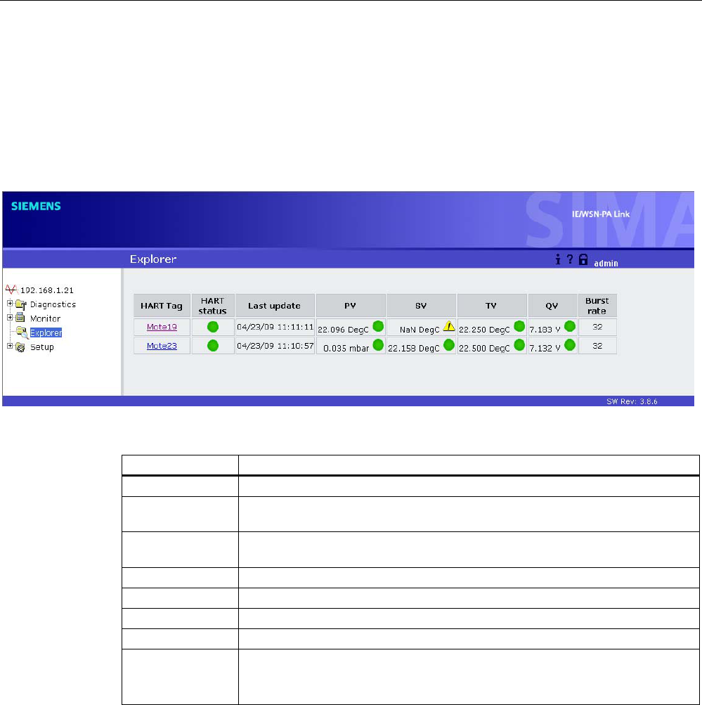
The "Explorer" page shows you an overview of your WirelessHART network.
Entry Description
HART tag Long HART tag or HART tag.
HART status HART status parameter, this is the overall device status. Hover over the status
icon for a more descriptive message.
Last update Time stamp of the last measurement received by the WirelessHART field
device.
PV Value of the HART primary variable (1st variable)
SV Value of the HART secondary variable (2nd variable)
TV Value of the HART tertiary variable (3rd variable)
QV Value of the HART quaternary variable (4th variable)
Burst rate Interval in which the WirelessHART field device transmits its measurement data
to the Link (see also section 210H4.3.20).
Some devices burst multiple messages and at different rates.

Commissioning, configuration and diagnostics
4.5 Monitor
IE/WSN-PA Link
40 Operating Instructions, Release 02/2010, C79000-G8976-C240-02
4.5 Monitor
4.5.1 68BMonitoring data points
On the "Monitor" pages, you can monitor individual data points or group data points together
and monitor them as a trend.
4.5.2 69BMonitor > Custom Page
Entry Description
All columns /
reduce columns
Shows all column categories or reduces columns to those configured in "Setup"
> "Page Options" > "Point Columns" (default Point, Name, Desc, Value, Status)
Restore order Clicking on the column header (Device, Device Desc, etc…) will sort data point
entries in ascending/descending order based on the information of the
associated column. Clicking "Restore order" will return the data points to the
order specified by the user.
Edit Navigates to the edit custom page in the web interface.
Device Long HART tag or HART tag
Device desc HART description. A common parameter in every HART device for descriptive
information.
Parameter HART parameter for the associated data point
Point Data point in the format "longHARTtag.parameter"
Name User-defined name
Desc User-defined description
Value Most recently registered value of the assigned data point
Units Engineering unit of measure
Status Status of the HART variables. Indicated by text and/or a status display symbol.
4.5.3 70BMonitor > Quick Point Data
Entry Description
All columns /
reduce columns
Shows all column categories or reduces columns to those configured in
Setup>Page Options>Point Columns (default Point, Value, Status)
Variable selector Selects whether PV, SV, TV, or QV is shown on this page.
Device Long HART tag or HART tag
Device desc HART description. A common parameter in every HART device for descriptive
information.
Parameter HART parameter for the associated data point
Point Assigned data point in the format LongHARTtag.parameter.
Value Most recently registered value of the assigned data point
Units Engineering unit of measure
Status Status of the HART variables. Indicated by text and/or a status display symbol.

Commissioning, configuration and diagnostics
4.5 Monitor
IE/WSN-PA Link
Operating Instructions, Release 02/2010, C79000-G8976-C240-02 41
4.5.4 71BMonitor > Point Data
Entry Description
All columns /
reduce columns
Shows all column categories or reduces columns to those configured in "Setup"
> "Page Options" > "Point Columns" (default Point, Value, Status)
All points / filter
points
Displays all HART parameters for all devices on the network or filters
parameters to show only parameters mapped in Modbus mapping or the OPC
browse tree (and Link PV).
Device Long HART tag or HART tag
Device desc HART description. A common parameter in every HART device for descriptive
information.
Parameter HART parameter for the associated data point
Point Assigned data point in the format LongHARTtag.parameter
Value Most recently registered value of the assigned data point
Units Engineering units of measure.
Status Status of the HART variables. Indicated by text and/or a status display
symbol.
4.5.5 72BMonitor > Trend > Graph > Custom Trend
Monitoring trends
To view the graph of a trend, click Monitor > Trend > Graph. The available trends are
displayed. Click the name of the trend you wish to view.
Entry Description
Separate Y axis /
common Y axis
Separates the Y axis of each data point to give better resolution of the value or
makes all data points share the same Y axis.
Print Captures an image of this page and sends to PC client’s default printer.
Time Time stamp indicating the time the trend function sampled the associated data
point. This is not the current value cached on the Link. It may not reflect the time
in which the measurement was taken or received.
Legend Legend for the trends

Commissioning, configuration and diagnostics
4.5 Monitor
IE/WSN-PA Link
42 Operating Instructions, Release 02/2010, C79000-G8976-C240-02
4.5.6 73BMonitor > Trend > Report
Trend reports
To view a report of a trend, click Monitor > Trend > Report. Choose the trend to report, then
select local time or server time, the start and end times, and CSV, Excel, or XML format. To
finish, click Generate Report.
Entry Description
Trend Selects the user-defined trend.
Start and end time
in
Chooses between the time established by the Link (server time) or the PC client
(local time).
Local time Time of the PC client
Server time Time of the Link
Start time Time when the report will start gathering data.
Input format: mm/dd/yy hh:mm:ss
End time Time when the report will end gathering data.
Input format: mm/dd/yy hh:mm:ss
Format File format for the report. This can be either a comma separated file (CSV),
Excel spreadsheet, or XML file.
Generate report Causes the Link to generate a report using the selected file format. The report
begins at the first data point after the start time and continues until the last data
point before the end time.

Commissioning, configuration and diagnostics
4.6 Diagnostics
IE/WSN-PA Link
Operating Instructions, Release 02/2010, C79000-G8976-C240-02 43
4.6 Diagnostics
4.6.1 74BDiagnostics > Network > Overview
Entry Description
Shows whether active advertising is activated or deactivated.
Active advertising causes the WirelessHART network to send wireless
messages looking for new or unreachable devices to join the network. Active
advertising is automatically activated for 60 minutes when the Link is first
powered up, a device becomes unreachable, or no devices are found.
Active advertising
Click "Setup" to enable/disable the function. The "Setup" > "Network" >
"Speed" menu opens.
Fast pipe Shows whether fast pipe is activated or deactivated. Fast pipe creates a
dedicated channel for communication to the selected device. Used for large
data transfers.
Wireless device count Total number of expected field devices
Live Number of field devices that are currently communicating on the
WirelessHART network.
Late Number of field devices that have missed at least 1 update, but are not yet
classified as stale.
Stale Number of field devices that have missed several updates, but are not yet
classified as unreachable.
Unreachable Number of field devices that have not communicated for 10 minutes or more
(also considered as offline).
Unknown Number of field devices with an unknown state (i.e. not live, late, stale, etc…).
Conventional HART
device count
Number of wired conventional HART field devices that are communicating via
a WirelessHART adapter.
Conventional HART field devices support the HART protocol up to and
including HART version V6.
Devices with service
denied
Number of field devices that have been denied bandwidth because a) too
many devices are on the WirelessHART network or b) the device has asked
for an update rate not currently supported by the Link.
Devices with critical
power failure
Number of field devices that have indicated a critical power failure and have
stopped sending updates.
Devices with
unknown names
Number of field devices whose long HART tag or HART tag is not currently
known (typical during the join process).
Devices with
undefined names
Number of field devices whose long HART tag or HART tag has been left
blank.
Devices with
duplicated names
Number of field devices with duplicate long HART tags or HART tags.
Devices with invalid
names
Number of field devices whose long HART tag or HART tag begins with a
slash or contains either a dot or comma.
System up time The total time the system has been operational without an interruption
(power-cycle, restart, failure, etc…).

Commissioning, configuration and diagnostics
4.6 Diagnostics
IE/WSN-PA Link
44 Operating Instructions, Release 02/2010, C79000-G8976-C240-02
4.6.2 75BDiagnostics > Network > Devices
Entry Description
32 character long HART tag. HART tag
If you click on a device in the "HART Tag" column, the "Network details", "Burst
statistics" and "Service status" submenus for this device are called and display
additional network information about the device.
Node state The state of the device: live, late, stale, joining, unreachable, or unknown.
Green = live
Yellow = late
Red = stale, joining, unreachable, or unknown
Position the mouse pointer over the node status icons to display more
detailed information.
Active neighbors Number of other field devices with a connection to this field device.
Neighbors Names of other neighboring field devices
Service denied Indicates whether the field device has been denied bandwidth because:
Too many devices are on the WirelessHART network.
or
The device has asked for an update rate not currently supported by the Link.
Missed updates Total number of updates that have not been received by the Link.
A…x…C…D… (x indicates a missed update where B should have been)
Discarded updates Total number of updates that have been ignored because they where received
out of order. A…C…B…D (update B will be discarded)
Reliability Percentage of expected data packets that have been received by the Link.
100% reliability means that every expected data packet was received.
Calculated in 15 minute cycles.
Path stability Percentage of transmitted packets that have successfully reached their
destination over a given path, averaged for all neighbor paths of this device and
calculated in 15 minute cycles.
Example:
- Neighbor A path stability = 100
- Neighbor B path stability = 90
Resulting path stability = 95
RSSI Average received signal strength indication (dBm) for the field device, as seen
by all its neighbors. Calculated in 15 minute cycles.
Joins Number of times the field device has joined the network within the last 15 minute
cycle.
Join time Time that the field device made its last successful join.
4.6.3 76BDiagnostics > Network > Join Failure
Entry Description
Join failure When a WirelessHART device fails to join the WirelessHART network. Most join
failures are due to security reasons (missing or incorrect join key, not on access
control list, etc…).

Commissioning, configuration and diagnostics
4.6 Diagnostics
IE/WSN-PA Link
Operating Instructions, Release 02/2010, C79000-G8976-C240-02 45
Entry Description
Last failure time Time the field device last attempted to join the WirelessHART network
Failure count Number of total join failures for this device
Device ID Unique device identification number
Name Long HART tag or HART tag of the field device
In access control
list
Indicates if the Device ID appears in the access control list (only when in access
control mode).
Online Indicates if the field device is communicating with the WirelessHART network.
Reset list Clears all entries for the join failure table.
Edit access control
list
Navigates to the access control list page in the Web-based user interface.
4.6.4 77BDiagnostics > Network > Invalid MICs
Entry Description
Message integrity
check
Diagnostic in each data packet that allows the Link to verify the packet source
and contents ().
Invalid MIC Packet received from field device is not valid. May indicate a security problem.
4.6.5 78BDiagnostics > Advanced > Network Stats
The values are the numbers since the commissioning of the Link, the last restart or the last
counter reset.
Entry Description
Tx requests Number of HART messages sent / transmitted by the Link to the field devices
Tx request
timeouts
Number of send requests from the Link without a response from the field
devices
Rx response
messages
Number of HART message responses received by the Link from the field
devices. Equal to Tx requests - Tx request timeouts
Rx burst
messages
Number of burst/published messages received by the Link from the field
devices. These messages are pushed from the field devices and not
requested/queried.
Requests received Number of HART messages requested by a user application. These messages
are forwarded to the radio to be transmitted. An example of user applications is
the Web-based user interface of the Link.
Responses sent Number of HART message responses received from field devices that are then
forwarded on to the requesting user application.
Average latency Time difference between when a message is time stamped in a field device and
when it is received by the Link’s WirelessHART radio. This value is the average
latency for the entire WirelessHART network.

Commissioning, configuration and diagnostics
4.6 Diagnostics
IE/WSN-PA Link
46 Operating Instructions, Release 02/2010, C79000-G8976-C240-02
Entry Description
Average reliability Percentage of expected data packets that have been received by the Link.
100% reliability means that every expected data packet was received. This
value is the average reliability for the entire WirelessHART network.
Reset counts Resets all values for this table.
4.6.6 79BDiagnostics > Advanced > Modbus Stats > Serial Stats
Entry Description
Messages receive Number of messages received from the Modbus master device.
Crc errors Number of cyclic redundancy check errors. Crc errors generally indicate noise in
transmission or problems with data integrity.
Messages transmit Number of response messages transmitted from the Link.
Error responses Number of error response messages transmitted from the Link.
Reset counts Resets all values for this table.
4.6.7 80BDiagnostics > Advanced > Modbus Stats > TCP Stats
Entry Description
Messages
received
Number of messages received from the Modbus TCP device.
Messages
transmitted
Number of response messages transmitted from the Link.
Error responses Number of error response messages transmitted from the Link.
Open connections Number of connections in which the other Modbus TCP device is not
communicating.
Accepted
connections
Number of connections to other Modbus TCP devices.
Reset counts Resets all values for this table.
4.6.8 81BDiagnostics > Advanced > System Stats
Entry Description
CPU Usage Central Processing Unit (CPU) utilization (time used by a process) by application
or kernel.
User Percentage of CPU utilization that occurred while executing at the user level
(application).
System Percentage of CPU utilization that occurred while executing at the system level
(kernel).
Total Total CPU utilization, user and system (as a percentage)

Commissioning, configuration and diagnostics
4.6 Diagnostics
IE/WSN-PA Link
Operating Instructions, Release 02/2010, C79000-G8976-C240-02 47
Entry Description
Ram Random Access Memory
Size Total memory or disk space.
Used Portion of memory or disk space that has been used
Main file system Disk space reserved for Link operating system, user interface pages and
configuration data
Temporary
filesystem
Disk space reserved for log files, user-defined pages, and user-defined trends
Logs Disk space taken by diagnostic log files
4.6.9 82BDiagnostics > Advanced > Client/Server
Entry Description
Server The WirelessHART Link web server application
Client PC client that is currently logged onto the Link
HG version IE/WSN-PA Link firmware version. Version 3.8.9 is the initial release version for
the IE/WSNPA Link.
Name Hostname assigned to the Link
Physical address Hardware MAC address for the primary and secondary Ethernet ports
HG serial number Link serial number (or final assembly number)
PM serial number Program manager serial number
HG model number Link model number
HG device ID Link unique identification number
HG hardware
revision
Hardware product version of the IE/WSN-PA Link
Network frequency Radio frequency band for operating WirelessHART field network. WirelessHART
networks operate at 2.4 GHz.
HART universal
revision
The major revision of HART specification that applies to this Link.
Browser name The Web browser application that is currently accessing the Link.
Browser version The Web browser version
Operating system Operating system of the PC client currently accessing the Link.
Screen width Screen width resolution for the PC client
Screen height Screen height resolution for the PC client
Color depth Number of colors used by the PC client to display images.
User agent info Information provided by Web browser for further identification
Java enabled Indicates whether Java script is enabled.
IP Address IP address of the PC client
Remote user User role used to log into the Link

Commissioning, configuration and diagnostics
4.7 Connecting the Link to SIMATIC S7 and SIMATIC PCS 7
IE/WSN-PA Link
48 Operating Instructions, Release 02/2010, C79000-G8976-C240-02
4.7 Connecting the Link to SIMATIC S7 and SIMATIC PCS 7
To connect the IE/WSN-PA Link to SIMATIC S7-300/400 or to integrate it in
SIMATIC PCS 7, software blocks and technical support are available at the following
addresses:
● SIMATIC S7
Siemens AG
Industrial Technologies
IT4Industry Customer-Support
Werner-von-Siemens-Straße 60
91052 Erlangen
Germany
Phone: +49 9131 7-461 11
Fax: +49 9131 7-447 57
E-mail: 88Hit4.industry@siemens.com
● SIMATIC PCS 7
Siemens AG
I IS IN E&C OC A KHE
Siemensallee 84
76187 Karlsruhe
Germany
Phone: +49 721 595-6380
E-mail: 89Hfunction.blocks.industry@siemens.com
IE/WSN-PA Link
Operating Instructions, Release 02/2010, C79000-G8976-C240-02 49
Upkeep and maintenance 5
5.1 Replacing devices
Replacing a device
Follow the steps below to replace your Link with a new IE/WSN-PA Link:
1. Save the configuration of the Link you are replacing on a PC ("Setup" > "System Backup"
> "Save").
2. Check to make sure the saved configuration file is valid and undamaged
The configuration file is saved in CSV format as a ZIP file.
3. Disconnect the Link from the power supply.
4. Connect the new IE/WSN-PA Link to the power supply and turn on the power.
5. Wait until the device startup is complete.
6. Go to the Web pages of the Link (see section 211H4.3) and load the previously saved
configuration file on the new Link ("Setup" > "System Backup" > "Restore" > "Upload
Configuration").
7. Re-analyze the bandwidth ("Setup" > "Network" > "Bandwidth") as soon as all field
devices are connected to the Link and are returning measured data. Update the
bandwidth if necessary.
5.2 Loading a new firmware version
Loading firmware
Follow the steps below to load a new firmware version:
1. Save the *.exe file of the new firmware on a PC/laptop.
2. Connect the PC/laptop to the Link (see section 212H4.2).
3. Go to the Web page "Setup" > "Security" > "User Accounts" and enable the option
"Enable factory support" (see section 213H4.3.8).
4. Then click "Submit".
You will be prompted to restart the applications of the Link. This leads you automatically
to the "Setup" > "Restart Apps" Web page.
5. Run the *.exe file on the connected PC.
The *.exe file has a wizard that guides you through the update.
Once loading the firmware is completed, the Link automatically returns to productive
operation.

Upkeep and maintenance
5.3 Reset to factory settings
IE/WSN-PA Link
50 Operating Instructions, Release 02/2010, C79000-G8976-C240-02
5.3 Reset to factory settings
Restoring the default parameter settings
CAUTION
Note that resetting to factory defaults deletes the entire configuration of the Link.
To reset to factory settings, follow the steps outlined below:
1. Open the page "Setup" > "System Backup" > "Restore" in the Web pages for configuring
the Link (section 214H4.3.13).
2. Click "Reset Defaults".
3. Click "OK".
4. To complete resetting the Link to default setting, select the "Restart Apps" button.
The restart process takes a couple of minutes to complete. The Link then works with the
default factory settings. It may be necessary to configure the network settings of the PC
to restore communication with the Link.
For network configuration, refer to section 215H4.2.

IE/WSN-PA Link
Operating Instructions, Release 02/2010, C79000-G8976-C240-02 51
Technical specifications 6
6.1 Technical specifications of the Link
IE/WSN-PA Link
The following technical specifications apply to the IE/WSN-PA Link:
Data transfer
Transmission speed Ethernet 10/100 Mbps
Transmission speed Modbus RTU 57 600, 38 400, 19 200 or 9 600 bps
Update time (burst rate) can be set (up to 60 minutes)
Maximum network size per IE/WSN-PA Link 100 field devices
Delay at a network size of:
100 field devices
50 field devices
max. 10 sec
max. 5 sec
Maximum distance from the IE/WSN-PA Link to the
next WirelessHART field device
100 m
Reliability > 99 %
Wireless technology and frequency range WirelessHARTTM, 2.4 to 2.5 GHz DSSS
Interfaces
Attachment to Ethernet RJ-45 jack (two)
10BaseT/100BaseTx
Modbus Terminals A + B
Power
Power supply (external) 24 V DC (20…28 V)
Current consumption
Current consumption max. 500 mA
Permitted ambient conditions
Operating temperature without accessories
Operating temperature when using the Harting
adapter cable
-40°C to +60°C
-25°C to +60°C
Relative humidity (operation) 10 to 90 %

Technical specifications
6.1 Technical specifications of the Link
IE/WSN-PA Link
52 Operating Instructions, Release 02/2010, C79000-G8976-C240-02
Construction
Dimensions (W x H x D) in mm 229 x 306 x 89
Weight 4,54 kg
Housing Low copper aluminum
Cable guides 4 cable feedthroughs 1/2" NPT
Seal Silicon
Degree of protection IP65 / NEMA 4X
EMC approval
EMC EN 61326-1 : 2006

Approvals
7.1 Approvals of the Link
IE/WSN-PA Link
54 Operating Instructions, Release 02/2010, C79000-G8976-C240-02
North American Certifications
FM Division 2, Non-Incendive
Nonincendive for Class I, Division 2, Groups A, B, C, and D.
Dust Ignition-proof for Class II, III, Division 1,
Groups E, F, and G; Indoors/outdoor locations;
NEMA Type 4X
Temperature Code: T4 (-40°C < Ta < 60°C)
Canadian Standards Association (CSA)
CSA Division 2, Non-Incendive
Suitable for Class I, Division 2, Groups A, B, C, and D.
Dust Ignition-proof for Class II, Groups E, F, and G;
Suitable for Class III Hazardous Locations.;
Install per Siemens drawing A5E02467236A.
Temperature Code: T4 (-40°C < Ta < 60°C)
CSA Enclosure Type 4X
Information on directives of the European Union
● ATEX Directive (94/9/EC)
complies with the ATEX Directive.
● Electromagnetic Compatibility (EMC) (2004/108/EC)
complies with the EMC directive:
● Directive (R&TTE)(1999/5/EC)
complies with the R&TTE Directive
You will find the EC Declaration of Conformity for this product on the Internet at the following
address:
91Hhttp://support.automation.siemens.com/WW/view/en/10805878
→ "Entry list" tab
Filter settings:
● Entry type: "Certificates"
● Certificate type: "EC Declaration of Conformity"
● Search item(s): IE/WSN-PA Link
Approvals
7.1 Approvals of the Link
IE/WSN-PA Link
Operating Instructions, Release 02/2010, C79000-G8976-C240-02 55
European certification
WARNING
Note that using the adapter cable affects the protection for hazardous areas and use in the
hazardous zones listed in Chapter 7 is no longer permitted. If you use the Harting adapter
cable to connect to Ethernet, the requirements for hazardous area approval are no longer
met. In this case, if you want to use the device for an application in which the hazardous
areas directive is relevant, you will need to obtain approval from the relevant test center.
● N1
ATEX Typ n
See notes below
Certification Number: Baseefa10ATEX0044X
ATEX-Kennzeichnung: Ex II 3 G
Ex nA nL IIC T4 (-40°C ≤ Ta ≤ 60°C)
Rated voltage: 28 V
● ND
ATEX Dust Ignition-proof
See note below
Certification Number: Baseefa10ATEX0045X
ATEX-Kennzeichnung: II 3 D
Ex tD A22 IP66 T135 (-40°C ≤ Ta ≤ 60°C)
Rated voltage: 28 V
● N7
IECEx Typ n
See notes below
Certification Number: IECEx BAS 10.0014X
Ex nA nL IIC T4 (-40°C ≤ Ta ≤ 60°C)
Rated voltage: 28 V
● NF
IECEx Dust Ignition-proof
See note below
Certification Number: IECEx BAS 10.0015X
Ex tD A22 IP66 T135 (-40°C ≤ Ta ≤ 60°C)
Rated voltage: 28 V
Conditions of safe use installing N1 and N7
The device is not capable of withstanding the 500 V insulation test required by Clause 6.8.1
of EN 6007915: 2005. This must be taken into account when installing the device.

Approvals
7.1 Approvals of the Link
IE/WSN-PA Link
56 Operating Instructions, Release 02/2010, C79000-G8976-C240-02
Conditions of safe use installing N1, N7, ND and NF
WARNING
The surface resistivity of the antenna is greater than one gigaohm. To avoid electrostatic
charge build-up, it must not be rubbed or cleaned with solvents or dry cloth.

IE/WSN-PA Link
Operating Instructions, Release 02/2010, C79000-G8976-C240-02 57
Biological compatibility A
A.1 Biological compatibility of the Link
Electromagnetic fields and health
The independent German Commission on Radiological Protection was commissioned by the
German Federal Ministry for the Environment to determine the possible thermal and non-
thermal dangers posed by electromagnetic fields in the range from 0 Hz to 300 GHz
according to current scientific knowledge and came to the following conclusion in issue 29
(see 216HReferences):
"The German Commission on Radiological Protection concludes that according to the latest
scientific literature no new scientific research is available with respect to proven health
hazards which would throw doubt upon the scientific evaluation which serves as the basis for
the ICNIRP safety concepts and the recommendations of the EU commission."
The SSK also concludes that below the current limit values, these is also no scientific
suspicion of health risks.
This assessment agrees with those of other national and international scientific commissions
and of the WHO (92Hwww.who.int/emf).
Accordingly and in view of the fact that WirelessHART devices are significantly below the
scientifically established limit values, it can be assumed that there are no health risks from
the electromagnetic fields of WirelessHART products.
For detailed information on this topic, refer to the references.

IE/WSN-PA Link
Operating Instructions, Release 02/2010, C79000-G8976-C240-02 59
References B
B.1 Sources of information and other documentation
Document Further information
Limit values and
precautionary
measures for
protecting the
population from
electromagnetic fields
German Commission on Radiological Protection, Bonn, Germany
Issue 29, 2001, ISBN 3-437-21527-2 (German)
Internet address: 93Hwww.ssk.de
Recommendation of the German Commission on Radiological Protection
with scientific reasoning
Various information on
the topic of
electromagnetic fields
and science
World Health Organization (WHO): 94Hwww.who.int/emf
International Commission of Non-ionizing Radiation Protection:
95Hwww.icnirp.de
German Association for Information Technology,
Telecommunications and New Media (BITKOM):
96Hwww.bitkom.org/de/themen_gremien/38383.aspx

IE/WSN-PA Link
Operating Instructions, Release 02/2010, C79000-G8976-C240-02 61
Training, Service & Support C
C.1 Training, Service & Support
Online support
In addition to our product documentation, the comprehensive online information platform
supports you in all aspects of our Service & Support at any time and from any location in the
world. You will find this on the Internet at the following address:
97Hwww.siemens.com/automation/service&support
Here, you will find the following information:
● Support news, newsletter
● Product information, Product Support, Applications & Tools
● Technical Forum
● Access to other features of our Service & Support offer:
– Technical Consulting
– Engineering Support
– Field Service
– Spare parts and repairs
– Optimization and modernization
– Technical Support
Expert advice on technical questions with a wide range of demand-optimized services
for all our products and systems.
98Hwww.siemens.de/automation/support-request
You will find contact addresses on the Internet at the following address:
99Hwww.automation.siemens.com/partner
SITRAIN - Siemens training for automation and industrial solutions
With over 300 different courses, SITRAIN covers the entire Siemens product and system
spectrum in the field of automation and drive technology. Advanced training tailored to your
needs is also available. In addition to our classic range of courses, we also offer a
combination of various training media and sequences. You can, for example, use self-study
programs on CD-ROM or on the Internet as preparation or to consolidate training.
You will find detailed information on our training curriculum and how to contact our customer
consultants at the following Internet address:
100Hwww.siemens.com/sitrain
IE/WSN-PA Link
Operating Instructions, Release 02/2010, C79000-G8976-C240-02 63
Glossary
Access Control List (ACL)
List with addresses of nodes that have the right to access a network. The access control list
serves as access protection for a network.
The IE/WSN-PA Link manages an access control list in which the addresses of the
WirelessHART sensors allowed to access the WSN are administered.
Bandwidth
Maximum throughput of a connecting cable (normally specified in bps).
Connectability
Typically refers to a combination of path statistics and link reliability. May also refer to the
operability of the connection between the Link and the control center.
Device (field device)
Relates to a WirelessHART transducer.
DHCP
Dynamic Host Configuration Protocol
A protocol for automatic assignment of IP addresses.
Domain name
Domain name
A unique identifier used on the Internet. It consists of characters with dots as delimiters, for
example: this.domain.com
HART
Highway Addressable Remote Transducer is a standardized and widely used
communications system for setting up industrial fieldbuses. It allows digital communication of
multiple nodes (field devices) over a common data bus. HART is based on the widespread 4-
20 mA standard (for transmission of analog signals). Existing cables of older systems can be
used directly and both systems operated parallel to each other. HART was developed in the
1980's by the Rosemount company for their field devices. In 1989, the HART standard was
initiated by the HART Communication Foundation (HCF). HART Communication Foundation
in Europe is based in Basle (Switzerland).

Glossary
IE/WSN-PA Link
64 Operating Instructions, Release 02/2010, C79000-G8976-C240-02
HART Version 7
Specification of HCF
The main focus is on "WirelessHART" communication of HART devices.
HCF
HART Communication Foundation
Host Name
A unique designator in a domain associated with the IP address of a device such as:
"device.this.domain.com". In that example the hostname is "device".
HTML
Hyper Text Markup Language: The file format used to define pages viewed with a web
browser.
HTTP
Hyper Text Transfer Protocol
Transfer protocol for Web pages in the Internet
HTTPS
HyperText Transfer Protocol Secure
Protocol for the encryption and authentication of communication between Web server and
Web browser in the World Wide Web.
Expansion of HTTP for secure transmission of confidential data with the aid of SSL.
ICNIRP
International Council on Non-Ionizing Radiation Protection
IEEE
Institute of Electrical and Electronics Engineers
IEEE 802.15.4
Specification for a protocol for wireless data transmission of devices with a low power
consumption and short range. It is used for all WirelessHART networks (WSN).
Industrial Ethernet
A bus system complying with IEEE 802.3 (ISO 8802-2)

Glossary
IE/WSN-PA Link
Operating Instructions, Release 02/2010, C79000-G8976-C240-02 65
IP (TCP/IP)
Internet Protocol
The IP protocol alone is connectionless and not allowed. The most important information is
the unique IP address. Blocks of data are sent to the target computer independent of each
other. Putting them in the right order is responsibility of TCP.
IP address
An IP address consists of a numeric code with four numbers between 0 and 255 (4 bytes),
separated by a dot, for example 192.168.0.55. It is the numeric address of a particular
computer in the network / Internet.
Join key
Hexadecimal code that connecting devices to the Link. This code must be identical in the
device and the Link.
Network
The portion of the network that the device resides on.
Network ID
Numeric code that links devices to the Link. This code must be identical in the device and
the Link.
Server
A server is a device or more generally an object, for example, a software program that can
provide certain services. The service is provided at the request of a client.
Services
Services provided by a communication protocol.
SIMATIC
Siemens automation system
Subnet
A subnet is part of a network whose parameters must be matched up. It includes bus
components and all the attached stations. Subnets can, for example, be connected together
by gateways to form a network.

Glossary
IE/WSN-PA Link
66 Operating Instructions, Release 02/2010, C79000-G8976-C240-02
Subnet mask
The subnet mask specifies which part of an IP address is used as the subnet address. In a
class B network(subnet mask 255.255.0.0), the first two fields of an IP address (for example
150.215 in the IP address 150.215.17.9) represent the subnet.
TCP/IP
TCP = Transport Connection Protocol
IP = Internet Protocol
WirelessHART
See 217HHART Version 7
WSN
Wireless Sensor Network
IE/WSN-PA Link
Operating Instructions, Release 02/2010, C79000-G8976-C240-02 67
1BIndex
C
Certificates, 53
Commissioning, 16
Components supplied with the IE/WSN-PA Link, 8
Configuration PC, connecting, 16
Creating trends, 37
D
Disable channel, 24
Documentation, 8
F
Factory set password, 15
R
Replacing a device, 49
W
Wireless channels, 24
WLAN node, 24

IE/WSN-PA Link
68 Operating Instructions, Release 02/2010, C79000-G8976-C240-02