Siemens IWPBV1 2.4/5 GHz IEEE 802.11a/b/g IWLAN/PB Link User Manual Vorabversion Zertifizierung 01
Siemens AG 2.4/5 GHz IEEE 802.11a/b/g IWLAN/PB Link Vorabversion Zertifizierung 01
UserManual.wiki
>
Siemens
>
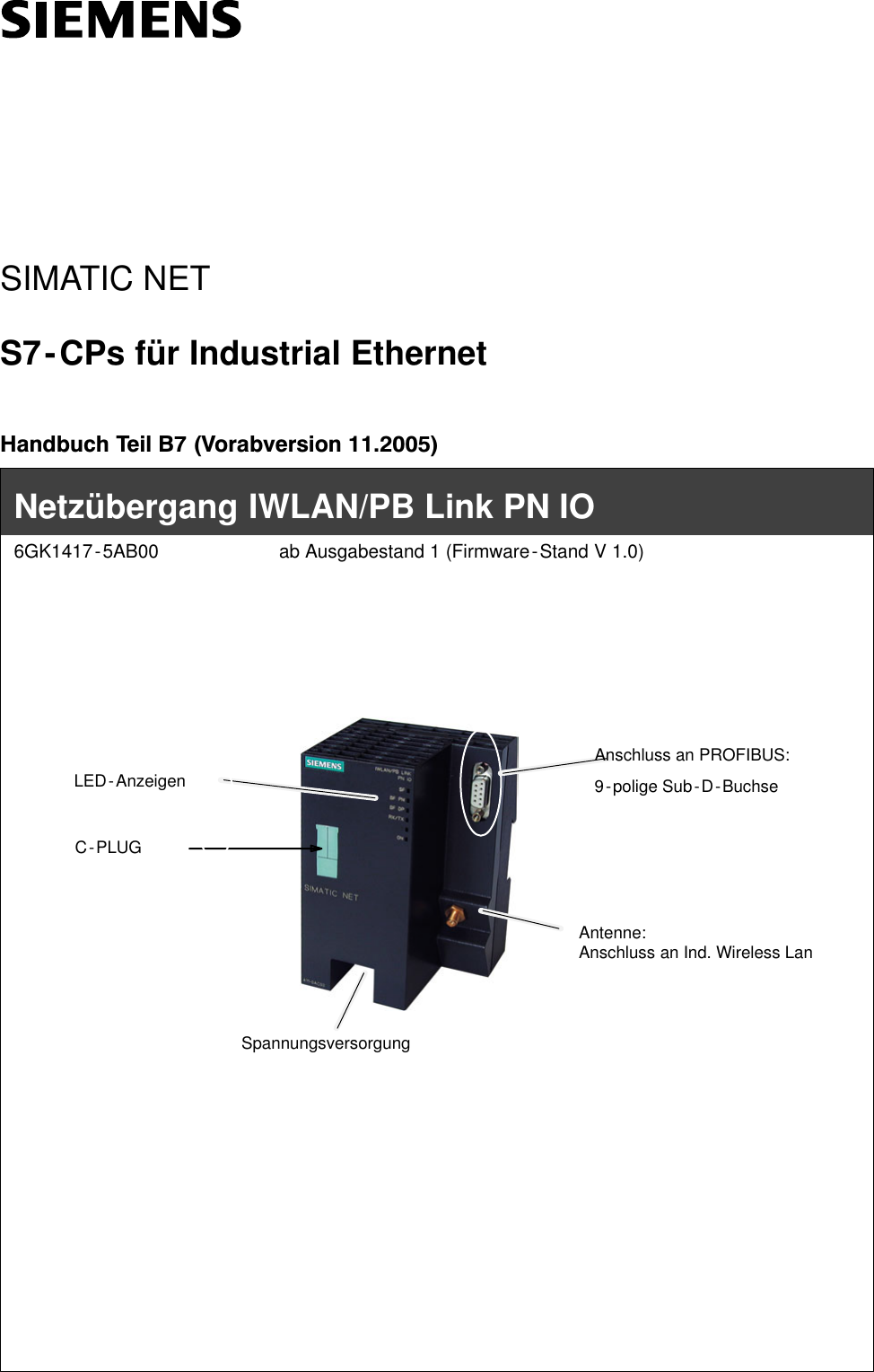
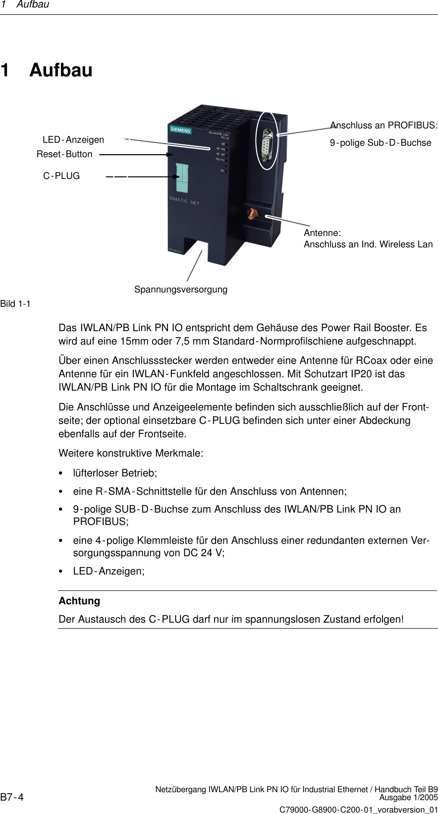
IWPBV1 User Manual
Users Manual
Navigation menu
Upload a User Manual
Namespaces
Wiki Guide
HTML
PDF
Info
Views
User Manual
Discussion / Help
Navigation