Siemens IWPBV1 2.4/5 GHz IEEE 802.11a/b/g IWLAN/PB Link User Manual Vorabversion Zertifizierung 01
Siemens AG 2.4/5 GHz IEEE 802.11a/b/g IWLAN/PB Link Vorabversion Zertifizierung 01
Siemens >
Users Manual

S
IMATIC NET
S
7-CPs für Industrial Ethernet
Handbuch Teil B7 (Vorabversion 11.2005)
LED-Anzeigen
Netzübergang IWLAN/PB Link PN IO
6GK1417-5AB00 ab Ausgabestand 1 (Firmware-Stand V 1.0)
Antenne:
Anschluss an Ind. Wireless Lan
Anschluss an PROFIBUS:
9-polige Sub-D-Buchse
C-PLUG
Spannungsversorgung

Produkthinweise
B7-2 Netzübergang IWLAN/PB Link PN IO für Industrial Ethernet / Handbuch Teil B9
Ausgabe 1/2005
C79000-G8900-C200-01_vorabversion_01
Produkthinweise
Produktbezeichnungen
In dieser Beschreibung finden Sie Informationen zum Produkt
SIWLAN/PB Link PN IO Bestell-Nr.: 6GK1417-5AB00
In Papierform beiliegende Produktinformation
Hinweis
Sämtliche Hinweise in der Produktinformation, die dem hier beschriebenen
Gerät beiliegt, sind gültig und unbedingt zu beachten.

Inhalt
B7-3
Netzübergang IWLAN/PB Link PN IO für Industrial Ethernet / Handbuch Teil B9
Ausgabe 1/2005
C79000-G8900-C200-01_vorabversion_01
Inhalt
Inhalt - Teil A
S7-CPs - allgemeine Informationen siehe allgemeiner Teil. . . . . . . . . . . . . . . . . .
Hinweis
Beachten Sie bitte den hier genannten Teil A des Handbuches; dieser gehört
ebenfalls zur Beschreibung des CPs / Link. Unter anderem finden Sie dort die Er-
klärung der verwendeten Sicherheitshinweise, die Literaturhinweise sowie weitere
Informationen, die für alle S7-CPs / IE/PB Link für Industrial Ethernet gelten.
Zum vorliegenden Teil B des Handbuches gehört folgender Ausgabestand des All-
gemeinen Teiles A: ab 12/2004
Sie können den aktuellen Allgemeinen Teil A auch über Internet beziehen:
http://www4.ad.siemens.de/view/cs/de/8777865
Inhalt - Teil B7
1 Aufbau B7-4. . . . . . . . . . . . . . . . . . . . . . . . . . . . . . . . . . . . . . . . . . . . . . . . . . . . . . . . . . . . . . . .
2 Montage und Inbetriebsetzung B7-5. . . . . . . . . . . . . . . . . . . . . . . . . . . . . . . . . . . . . . . . . .
2.1 So gehen sie vor B7-5. . . . . . . . . . . . . . . . . . . . . . . . . . . . . . . . . . . . . . . . . . . . .
2.1.1 Spannungsversorgung B7-9. . . . . . . . . . . . . . . . . . . . . . . . . . . . . . . . . . . . . . . .
2.2 C-PLUG (Configuration Plug) B7-10. . . . . . . . . . . . . . . . . . . . . . . . . . . . . . . . . .
3 Technische Daten B7-11. . . . . . . . . . . . . . . . . . . . . . . . . . . . . . . . . . . . . . . . . . . . . . . . . . . . . .
1 Aufbau
B7-4 Netzübergang IWLAN/PB Link PN IO für Industrial Ethernet / Handbuch Teil B9
Ausgabe 1/2005
C79000-G8900-C200-01_vorabversion_01
1 Aufbau
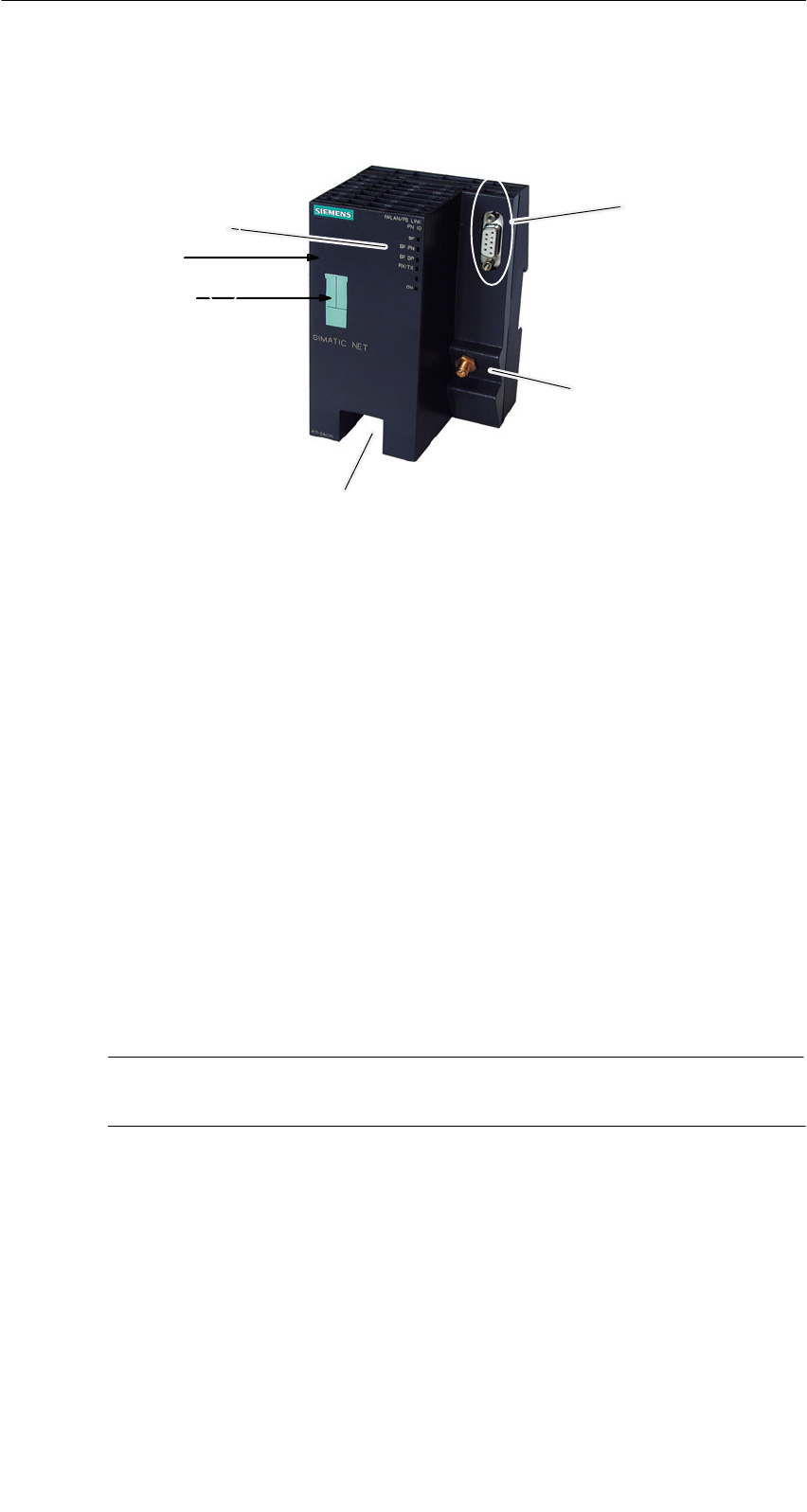
LED-Anzeigen
Anschluss an PROFIBUS:
9-polige Sub-D-Buchse
C-PLUG
Antenne:
Anschluss an Ind. Wireless Lan
Spannungsversorgung
Reset-Button
Bild 1-1
Das IWLAN/PB Link PN IO entspricht dem Gehäuse des Power Rail Booster. Es
wird auf eine 15mm oder 7,5 mm Standard-Normprofilschiene aufgeschnappt.
Über einen Anschlussstecker werden entweder eine Antenne für RCoax oder eine
Antenne für ein IWLAN-Funkfeld angeschlossen. Mit Schutzart IP20 ist das
IWLAN/PB Link PN IO für die Montage im Schaltschrank geeignet.
Die Anschlüsse und Anzeigeelemente befinden sich ausschließlich auf der Front-
seite; der optional einsetzbare C-PLUG befinden sich unter einer Abdeckung
ebenfalls auf der Frontseite.
Weitere konstruktive Merkmale:
Slüfterloser Betrieb;
Seine R-SMA-Schnittstelle für den Anschluss von Antennen;
S9-polige SUB-D-Buchse zum Anschluss des IWLAN/PB Link PN IO an
PROFIBUS;
Seine 4-polige Klemmleiste für den Anschluss einer redundanten externen Ver-
sorgungsspannung von DC 24 V;
SLED-Anzeigen;
Achtung
Der Austausch des C-PLUG darf nur im spannungslosen Zustand erfolgen!
2 Montage und Inbetriebsetzung
B7-5
Netzübergang IWLAN/PB Link PN IO für Industrial Ethernet / Handbuch Teil B9
Ausgabe 1/2005
C79000-G8900-C200-01_vorabversion_01
2 Montage und Inbetriebsetzung
2.1 So gehen sie vor
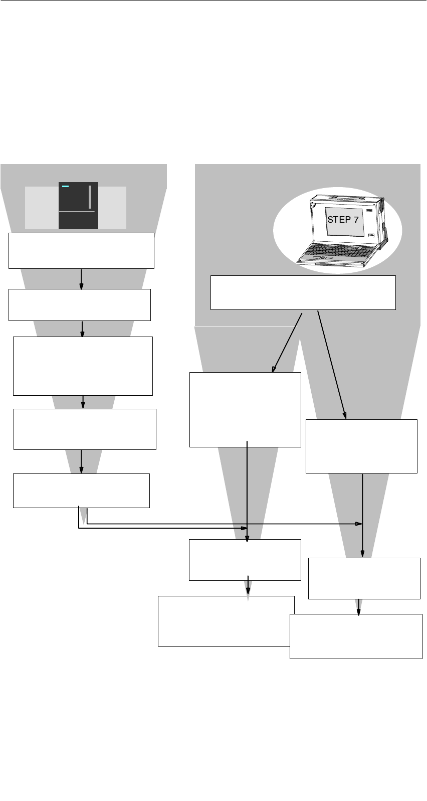
Gehen Sie gemäß der folgenden Darstellung vor; beachten sie bitte die zusätzli-
chen Hinweise in diesem Kapitel. Die Montage und die Projektierung können zu-
nächst unabhängig voneinander durchgeführt werden.
Laden bzw. aktualisieren Sie
die Datenbasis (Projektierung)
des zugehörigen PROFINET
IO-Controllers
Montieren Sie IWLAN/PB Link PN
IO auf einer Hutschiene
Schließen Sie die Stromversor-
gung an.
Schließen Sie das Gerät an
PROFIBUS und über die Antenne
an WLAN an.
Installieren Sie auf einem PG/PC die
Projektiersoftware STEP 7
Konfigurieren Sie IWLAN/
PB Link PN IO als
S7-300 Station mit
HW Konfig.
Schalten Sie die Stromversor-
gung ein.
Laden Sie die Datenbasis (Pro-
jektierung) von STEP 7 aus in
das IWLAN/PB Link PN IO.
Projektierung: (siehe auch Kap. 4):Montage:
Weisen Sie dem IWLAN/
PB Link PN IO eine IP-
Adresse zu.
Konfigurieren Sie das IW-
LAN/PB Link PN IO als
IO-Device an einem PN-
IO-System
(Proxy mit angeschlosse-
nem DP-Mastersystem)
Einsatz nur als
Netzübergang
siehe Kap.4.1
Einsatz als PROFINET
IO-Device und als
Netzübergang
siehe Kap.4.2
Weisen Sie dem IWLAN/
PB Link PN IO einen Ge-
rätenamen zu.
Übernehmen Sie die im
PRESET-PLUG projektierten
Voreinstellungen wie in Kap.2.2
beschrieben.
2 Montage und Inbetriebsetzung
B7-6 Netzübergang IWLAN/PB Link PN IO für Industrial Ethernet / Handbuch Teil B9
Ausgabe 1/2005
C79000-G8900-C200-01_vorabversion_01
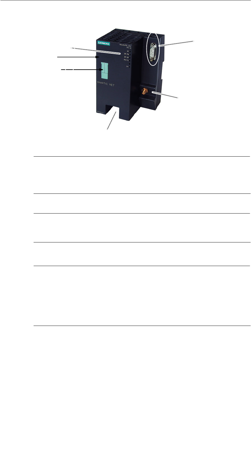
LED-Anzeigen
Anschluss an PROFIBUS:
9-polige Sub-D-Buchse
C-PLUG /
PRESET PLUG
Antenne:
Anschluss an Ind. Wireless Lan
Spannungsversorgung
Reset-Button
Bild 2-1
Achtung
Wichtige Hinweise zu Montage und Betrieb:
SDie Montage muss so erfolgen, daß die oberen und unteren Lüftungsschlitze
der Baugruppe nicht verdeckt werden und eine gute Durchlüftung möglich ist.
Hinweis
Der PROFIBUS-Anschluss kann auch bei eingeschalteter Vesorgungsspannung
vorgenommen werden.
Hinweis
Die Anforderungen nach EN61000-4-5, Surge Prüfung auf Spannungsversor-
gungsleitungen, werden nur erfüllt bei Einsatz eines Blitzductor VT AD 24V Art. Nr.
918 402 .
Hersteller:
DEHN+SÖHNE GmbH+Co.KG Hans Dehn Str.1 Postfach 1640 D-92306 Neu-
markt

2 Montage und Inbetriebsetzung
B7-7
Netzübergang IWLAN/PB Link PN IO für Industrial Ethernet / Handbuch Teil B9
Ausgabe 1/2005
C79000-G8900-C200-01_vorabversion_01
!Warnung
Das Produkt IWLAN/PB Link PN IO muss in ein Gehäuse oder einen Schalt-
schrank eingebaut werden.
Im Geltungsbereich der ATEX 100a (EN 50021) muß dieses Gehäuse mindestens
IP54 nach EN 60529 entsprechen.
WARNUNG
DAS GERÄT DARF NUR DANN AN DIE SPANNUNGSVERSORGUNG ANGE-
SCHLOSSEN ODER VON IHR GETRENNT WERDEN, WENN EINE EXPLO-
SIONSGEFAHR MIT SICHERHEIT AUSGESCHLOSSEN WERDEN KANN.

2 Montage und Inbetriebsetzung
B7-8 Netzübergang IWLAN/PB Link PN IO für Industrial Ethernet / Handbuch Teil B9
Ausgabe 1/2005
C79000-G8900-C200-01_vorabversion_01
Erdungs-/Massekonzept
Die Erdung erfolgt über die Hutschiene.
PG/PC-Anschluß
Sie können das PG zur Projektierung wie folgt anschließen:
Süber Industrial Wireless LAN (empfohlen)
Für eine Projektierung über Industrial Wireless LAN muss das IWLAN/PB Link
PN IO zuvor mit einer IP-Adresse versorgt werden. Beachten Sie hierzu bitte
die Anleitung zur erstmaligen Adressierung im Kapitel 4.
Süber PROFIBUS
Für eine Projektierung über PROFIBUS muss das IWLAN/PB Link PN IO zuvor
mit der PROFIBUS-Adresse versorgt werden. Beachten Sie hierzu bitte die
Anleitung zur Adressierung im Kapitel 4.
Baugruppenzubehör
Das für den Anschluß von IWLAN/PB Link PN IO an ein Industrial Wireless LAN
und PROFIBUS LAN benötigte Zubehör (Stromversorgung) ist gesondert zu be-
stellen.
Ebenfalls separat bestellbar ist das optional einsetzbare C-PLUG.
Ausführliche Informationen und Bestelldaten finden Sie im Katalog IK PI.
2 Montage und Inbetriebsetzung
B7-9
Netzübergang IWLAN/PB Link PN IO für Industrial Ethernet / Handbuch Teil B9
Ausgabe 1/2005
C79000-G8900-C200-01_vorabversion_01
2.1.1 Spannungsversorgung
!Warnung
Das Gerät IWLAN/PB Link PN IO ist für den Betrieb mit Sicherheitskleinspannung
ausgelegt. Entsprechend dürfen an die Versorgungsanschlüsse nur Sicherheits-
kleinspannungen (SELV) nach IEC950/EN60950/ VDE0805 angeschlossen wer-
den.
Das Netzteil für die Versorgung des IWLAN/PB Link PN IO muss NEC Class 2
entsprechen (Spannungsbereich 20,4-28,8 V, Strombedarf 300 mA).
Das Gerät darf nur mit einer Stromversorgungseinheit versorgt werden, die die
Anforderungen der Klasse 2 für Stromversorgungen der ”National Electrical
Code,table 11 (b)” erfüllt. Bei einem Aufbau mit redundanter Stromversorgung
(zwei getrennte Stromversorgungen) müssen beide Stromversorgungen mit ihrer
Leistung insgesamt diese Anforderungen erfüllen.
Ausnahmen:
SDie Versorgung durch PELV (entsprechend VDE 0100-410) ist ebenfalls zuläs-
sig, sofern die erzeugte Nennspannung die Spannungsgrenzen 25 V AC oder
60 V DC nicht überschreitet.
SDie Versorgung durch SELV-Stromquelle (entsprechend IEC 60950) oder
PELV-Stromquelle (entsprechend VDE 0100-410) ohne begrenzte Leistung ist
ebenfalls zulässig, sofern geeignete Brandschutzmaßnahmen getroffen werden
durch:
- Einbau in einen Schrank oder ein geeignetes Gehäuse
- Einbau in einen entsprechend ausgestatteten, geschlossenen Betriebsraum
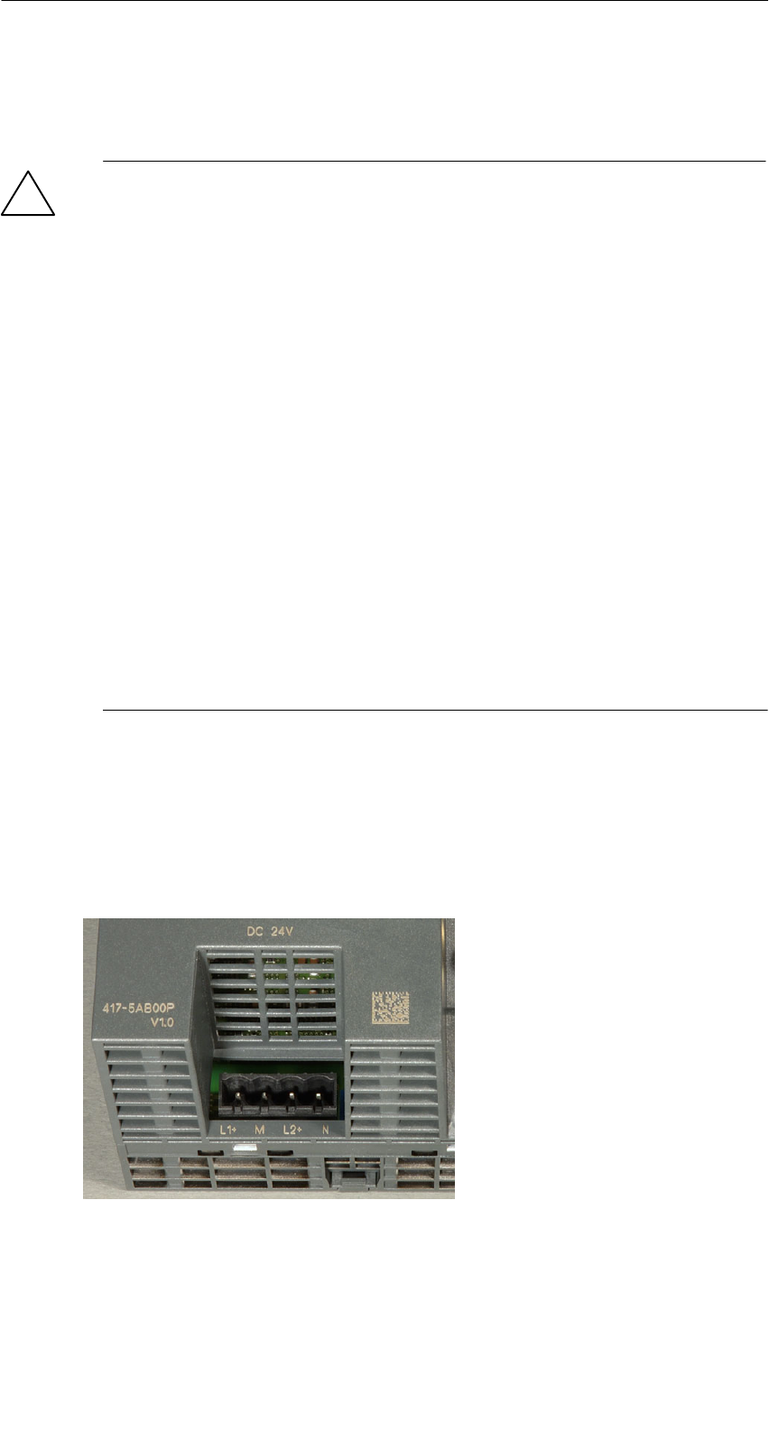
Der Anschluss der Spannungsversorgung erfolgt über einen 4-poligen steckbaren
Klemmenblock. Die Spannungsversorgung ist redundant anschließbar. Beide Ein-
gänge sind entkoppelt. Es besteht keine Lastverteilung. Bei redundanter Einspei-
sung versorgt das Netzteil mit der höheren Ausgangsspannung das IWLAN/
PB Link PN IO alleine. Die Spannungsversorgung ist hochohmig mit dem Gehäuse
verbunden, um einen erdfreien Aufbau zu ermöglichen.
L1+: +24V DC
M: Masse 24V DC
L2+: +24V DC
M: Masse 24V DC
Bild 2-2 Spannungsversorgung

2 Montage und Inbetriebsetzung
B7-10 Netzübergang IWLAN/PB Link PN IO für Industrial Ethernet / Handbuch Teil B9
Ausgabe 1/2005
C79000-G8900-C200-01_vorabversion_01
2.2 Inbetriebsetzung mit dem PRESET-PLUG
Übersicht
Der PRESET-PLUG dient dazu, WLAN-Geräten wie APs, ECMs oder IWLAN/
PB-Links auf einfachste Weise eine definierte Voreinstellung zu geben.
Der PRESET-PLUG wird zunächst in einem SCALANCEW mit den gewünschten
WLAN Parametern konfiguriert und anschließend für die Inbetriebnahme in den
C-PLUG Steckplatz des Zielgerätes gesteckt.
Diese Vorgehensweise ist insbesondere bei der Inbetriebnahme vieler gleich para-
metrierter WLAN-Clients von Vorteil, da dann nicht jeder Client manuell parame-
triert werden muss.
Achtung
Der PRESET-PLUG ist nur für die Inbetriebnahme vorgesehen. Der WLAN Be-
trieb mit gestecktem PRESET-PLUG ist nicht möglich.
PRESET-PLUG konfigurieren
Zur Konfiguration eines PRESET-PLUG benötigen Sie ein Gerät vom Typ
SCALANCE W788.
Sie können mit der beschriebenen Vorgehensweise sowohl einen PRESET-PLUG
neu konfigurieren als auch eine bestehende Konfiguration ändern.
Gehen Sie so vor:
Schritt Vorgehen
1. Stecken Sie einen neuen oder bereits konfigurierten PRESET-PLUG in den
C-PLUG Steckplatz des ausgeschalteten SCALANCE W.
2. Schalten Sie das Gerät ein.
3. Öffnen Sie das Web Interface des SCALANCE W. Im Web Interface werden die
aktuellen Einstellungen des PRESET-PLUG angezeigt (bei bereits bestehen-
der Konfiguration). Sie können nun die Parameter ändern.
4. Stellen Sie alle Parameter so ein, wie Sie für die Voreinstellung der Zielgeräte
benötigt werden.
5. Wählen Sie zuerst, ob das Zielgerät als AP oder Client arbeiten soll.
6. Wenn Sie alle Parameter eingestellt haben, öffnen Sie das Menu System "
C-PLUG und wählen die Funktion ”Create PRESET-PLUG”.
7. Wählen sie den Gerätetyp des Zielgerätes aus, für welchen dieser PRESET-
PLUG gedacht ist.

2 Montage und Inbetriebsetzung
B7-11
Netzübergang IWLAN/PB Link PN IO für Industrial Ethernet / Handbuch Teil B9
Ausgabe 1/2005
C79000-G8900-C200-01_vorabversion_01
Schritt Vorgehen
8. Schließen Sie die Konfiguration mit der Schaltfläche ”Modify” ab.
Der PRESET-PLUG ist damit erstellt.
9. Schalten Sie das SCALANCE W aus und entnehmen Sie den PRESET-
PLUG.
Der so erstellte PRESET-PLUG funktioniert nur bei dem von Ihnen gewählten Ge-
rätetyp.
Zielgerät mit PRESET-PLUG In Betrieb nehmen
Die Preset Funktion des PRESET-PLUGs funktioniert nur, wenn der PRESET-
PLUG zuvor für das zu parametrierende Gerät erzeugt wurde.
Gehen sie so vor:
Schritt Vorgehen
1. Schalten Sie zuerst das Zielgerät aus
2. Stecken Sie den PRESET-PLUG in den C-PLUG Steckplatz.
3. Schalten Sie das Zielgerät ein.
Es blinken verschiedene LEDs als Zeichen dass ein PRESET-PLUG erkannt
wurde. Das genaue LED Bild für die PRESET-PLUG Funktion können Sie der
LED Beschreibung des Geräts entnehmen.
4. Betätigen Sie den Reset-Taster neben dem C-PLUG Steckplatz.
Die Voreinstellungen des PRESET-PLUGs werden jetzt auf das Gerät kopiert
und dort gespeichert. Ist dies erfolgreich geschehen, ändert sich der Zustand
der LEDs von Blinken auf Dauerlicht.
5. Schalten Sie nun das Zielgerät aus und entnehmen Sie den PRESET-PLUG.
Mit dem nächsten Einschalten läuft das Zielgerät mit den vom PRESET-PLUG
übertragenen Parametern an.
Allgemeine Hinweise
SIP-Parameter bleiben unverändert
Um eine Verdopplung von IP Adressen zu vermeiden, werden die IP Parameter
durch anwenden des PRESET-PLUGs nicht verändert sondern bleiben erhal-
ten.
SWLAN Interface ist deaktiviert
Ist der PRESET-PLUG gesteckt, wird das WLAN Interface des Geräts deakti-
viert. Der WLAN Betrieb mit gestecktem PRESET-PLUG ist nicht möglich.
2 Montage und Inbetriebsetzung
B7-12 Netzübergang IWLAN/PB Link PN IO für Industrial Ethernet / Handbuch Teil B9
Ausgabe 1/2005
C79000-G8900-C200-01_vorabversion_01
2.3 C-PLUG (Configuration Plug)
Wechselmedium C-Plug als Alternative zum Flash-Speicher
Das IWLAN/PB Link PN IO besitzt zur Aufnahme der Projektierdaten einen inter-
nen Flash-Speicher. Optional kann das Gerät mit einem C-PLUG Wechselme-
dium (Configuration Plug) betrieben werden.
Das IWLAN/PB Link PN IO kann mit oder ohne C-PLUG betrieben werden. Der
vorhandene Flash-Speicher wird nur dann genutzt, wenn kein C-PLUG gesteckt
ist.
Wenn ein C-PLUG gesteckt ist, werden die Projektierdaten immer auf diesem ge-
speichert. Dadurch wird der Ersatzteilfall vereinfacht. Durch einfachen C-PLUG
Austausch können alle Daten ohne Programmiergerät in ein Ersatzgerät übernom-
men werden.
Achtung
SWenn ein C-PLUG gesteckt ist, der keine für das IWLAN/PB Link PN IO gül-
tige Formatierung oder keine gültigen Daten besitzt, läuft das IWLAN/
PB Link PN IO nicht an! Gerätezustand: “STOP mit Fehler”.
Sie müssen in diesem Fall den C-PLUG neu formatieren (mittels NCM-
Diagnose) oder durch ein C-PLUG mit gültigen Daten ersetzen.
SDer C-PLUG darf nur im spannungslosen Zustand gesteckt oder entnommen
werden !
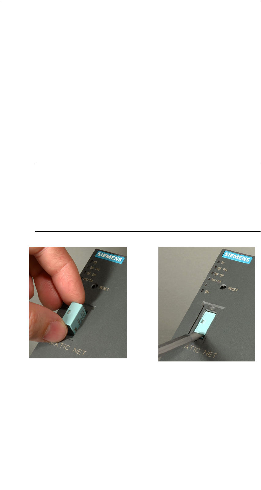
Bild 2-3 C-PLUG in das IWLAN/PB Link PN IO einsetzen und C-PLUG mit Hilfe eines Schraubendre-
hers aus dem IWLAN/PB Link PN IO entnehmen

2 Montage und Inbetriebsetzung
B7-13
Netzübergang IWLAN/PB Link PN IO für Industrial Ethernet / Handbuch Teil B9
Ausgabe 1/2005
C79000-G8900-C200-01_vorabversion_01
Tabelle 2-1 Betriebsverhalten beim C-PLUG Einbau
Vorgang / Status Verhalten bei Datenübernahme Ergebnis nach Anlauf
Auslieferungszustand (nach Konfiguration mit PRESET-PLUG) - Betrieb ohne C-PLUG
SFlash-Speicher leer
Skein C-PLUG gesteckt.
Projektierdaten werden aus dem
STEP 7-Projekt übernommen. Hier-
bei ist zu unterscheiden:
SEinsatz nur als Netzübergang:
Projektierdaten werden über die
Ladefunktion von STEP 7 über-
tragen.
SEinsatz als PROFINET IO-De-
vice: Projektierdaten werden
vom PROFINET IO-Controller
übertragen.
Das IE/PB Link PN IO läuft mit den
auf den Flash-Speicher übertrage-
nen Projektierdaten. 1)
Baugruppe wird im Auslieferungszustand (nach Konfiguration mit PRESET-PLUG) mit C-PLUG be-
stückt
SFlash-Speicher leer
SLeeres C-PLUG wird
gesteckt.
Projektierdaten werden aus dem
STEP 7-Projekt übernommen. Hier-
bei ist zu unterscheiden:
SEinsatz als PROFINET IO-De-
vice: Projektierdaten werden
vom PROFINET IO-Controller
übertragen.
SEinsatz nur als Netzübergang:
Projektierdaten werden über die
Ladefunktion von STEP 7 über-
tragen.
Das IE/PB Link PN IO läuft mit den
auf den C-PLUG übertragenen Pro-
jektierdaten. 1)
SFlash-Speicher leer
SC-PLUG mit Projektier-
daten wird gesteckt.
Voraussetzung: Projek-
tierdaten müssen für das
IE/PB Link PN IO gültig
sein 2)
Ergebnis nach Anlauf:
Das IE/PB Link PN IO läuft mit den
auf dem C-PLUG gespeicherten
Projektierdaten.
Das IE/PB Link PN IO läuft mit den
auf dem C-PLUG vorhandenen
Projektierdaten. 1)

2 Montage und Inbetriebsetzung
B7-14 Netzübergang IWLAN/PB Link PN IO für Industrial Ethernet / Handbuch Teil B9
Ausgabe 1/2005
C79000-G8900-C200-01_vorabversion_01
Tabelle 2-1 Betriebsverhalten beim C-PLUG Einbau, Fortsetzung
Vorgang / Status Ergebnis nach AnlaufVerhalten bei Datenübernahme
Baugruppe wird im Betriebszustand mit C-PLUG bestückt
SFlash-Speicher mit Pro-
jektierung
SLeeres C-PLUG wird
gesteckt.
Beim Anlauf des IE/PB Link PN IO
werden die Projektierdaten vom
Flash-Speicher auf den C-PLUG
geladen
Die Projektierdaten im Flash-Spei-
cher werden gelöscht.
Das IE/PB Link PN IO läuft mit den
vom Flash-Speicher auf das C-
PLUG übernommenen Projektierda-
ten. 1)
SFlash-Speicher mit Pro-
jektierung
SC-PLUG mit Projektier-
daten wird gesteckt
Voraussetzung: Projek-
tierdaten müssen für da
s
IE/PB Link PN IO gültig
sein 2)
Sofern der C-PLUG für das IE/PB
Link PN IO gültige Projektierdaten
enthält, werden diese Projektierda-
ten verwendet; die Daten im Flash-
Speicher werden ignoriert.
Beim nächsten Anlauf wird der in-
terne Flash-Speicher gelöscht.
Ergebnis:
Das IE/PB Link PN IO läuft mit den
auf dem C-PLUG gespeicherten
Projektierdaten. 1)
sein 2)
1) Anmerkung zum Einsatz als PROFINET IO-Device: nur der Gerätename wird remanent im C-PLUG
gespeichert; Projektierdaten werden bei jedem neuen Hochlauf vom PROFINET IO-Controller übertragen
und im temporären Speicher abgelegt.
2) Hinweis: Sofern der C-PLUG für das IE/PB Link PN IO keine gültigen Projektierdaten enthält, läuft das
Gerät nicht an! Bitte verwenden sie in diesem Fall NCM-Diagnose zur weiteren Klärung und ggf. zur For-
matierung des C-PLUG.

3 Technische Daten
B7-15
Netzübergang IWLAN/PB Link PN IO für Industrial Ethernet / Handbuch Teil B9
Ausgabe 1/2005
C79000-G8900-C200-01_vorabversion_01
3 Technische Daten
Datenübertragung / Unterstützte Über-
tragungsgeschwindigkeiten
SÜbertragungsrate Funk
SUnterstützte Standards Funk
1..54 Mbit/s
802.11a, 802.11b, 802.11g
SPROFIBUS 9,6 kbit/s, 19,2 kbit/s, 45,45 kbit/s, 93,75 kbit/s
187,5 kbit/s, 500 kbit/s, 1,5 Mbit/s, 3 Mbit/s
6 Mbit/s, 12 Mbit/s
Maximale Stromaufnahme an der PRO-
FIBUS-Schnittstelle beim Anschluss von
Netzkomponenten (beispielsweise opti-
sche Netzkomponenten)
100 mA bei 5V
Schnittstellen
Industrial Wireless LAN
Anschluss an PROFIBUS
R-SMA-Antennenbuchsen
9-polige Sub-D-Buchse
Versorgungsspannung 2 Einspeisungen für
DC +20,4 V bis 28,8 V
Die Versorgungsspannung ist galvanisch getrennt; es besteht
hochohmige Verbindung (>700kΩ) mit der Kontaktfeder zur
Montage des Gehäuses auf der Hutschiene).
Stromaufnahme
Saus DC 24 V extern ca. 0,3 A (typisch bei 24 V)
Verlustleistung 6,5 W
Zul. Umgebungsbedingungen
SBetriebstemperatur
STransport-/Lagertemperatur
SRelative Feuchte max.
SBetriebshöhe
0 °C bis +60 °C
-40 °C bis +70 °C
95% bei +25 °C
bis 2000 m über NN
Konstruktiver Aufbau
Baugruppenformat:
SMaße (B x H x T) in mm
SGewicht etwa
Kompaktbaugruppe
90 x 132 x 75
300 g
Darüberhinaus gelten für das IWLAN/PB Link PN IO sämtliche in /1/ S7-300 Bau-
gruppendaten: Referenzhandbuch im Kapitel ”Allgemeine technische Daten” aufge-
listeten Angaben zu
SElektromagnetischer Verträglichkeit;
STransport- und Lagerbedingungen;
SMechanischen und klimatischen Umgebungsbedingungen;
SIsolationsprüfungen, Schutzklasse und Schutzgrad.
Ausnahme: Die Abmessungen der Baugruppe und die Montage entsprechen nicht
den Angaben zu SIMATIC S7-300.
S
IMATIC NET
S
7-CPs for Industrial Ethernet
Manual Part B7 (Preliminary Version 11.2005)
LED displays
IWLAN/PB Link PN IO Gateway
6GK1417-5AB00 as of version 1 (firmware version V 1.0)
Antenna:
Attachment to Ind. Wireless
LAN
Attachment to PROFIBUS:
9-pin D-sub female
connector
C-PLUG
Power supply

Notes on the Product
2IWLAN/PB Link PN IO Gateway for Industrial Ethernet / Manual Part B9
Release 1/2005
C79000-G8976-C200-01_vorabversion_01
Notes on the Product
Product Names:
This description contains information on the product
SIWLAN/PB Link PN IO order no.: 6GK1417-5AB00
Product Information Accompanying the Product
Note
All the notices in the Product Information Bulletin shipped with this device are
valid and must be adhered to.

Contents
3
IWLAN/PB Link PN IO Gateway for Industrial Ethernet / Manual Part B9
Release 1/2005
C79000-G8976-C200-01_vorabversion_01
Contents
Contents - Part A
S7-CPs - General information see general part. . . . . . . . . . . . . . . . . . . . . . . .
Note
Please remember that Part A of the manual also belongs to the description of the
CP / Link. Among other things, it contains explanations of the safety notices, the
references, and general information that applies to all S7 CPs / IE/PB Link for
Industrial Ethernet.
The general Part A: as of 12/2004 belongs to this Part B
You can download the current general Part A from the Internet:
http://www4.ad.siemens.de/view/cs/en/8777865
Contents - Part B
1 Construction 4. . . . . . . . . . . . . . . . . . . . . . . . . . . . . . . . . . . . . . . . . . . . . . . . . . . . . . . . . .
2 Installation and Commissioning 5. . . . . . . . . . . . . . . . . . . . . . . . . . . . . . . . . . . . . . . . .
2.1 How to... 5. . . . . . . . . . . . . . . . . . . . . . . . . . . . . . . . . . . . . . . . . . . . . . . . . . . .
2.1.1 Power Supply 9. . . . . . . . . . . . . . . . . . . . . . . . . . . . . . . . . . . . . . . . . . . . . . . .
2.2 C-PLUG (Configuration Plug) 10. . . . . . . . . . . . . . . . . . . . . . . . . . . . . . . . . .
3 FCC Approval 11. . . . . . . . . . . . . . . . . . . . . . . . . . . . . . . . . . . . . . . . . . . . . . . . . . . . . . . . . .
3 Technical Specifications 12. . . . . . . . . . . . . . . . . . . . . . . . . . . . . . . . . . . . . . . . . . . . . . . .
1 Construction
4IWLAN/PB Link PN IO Gateway for Industrial Ethernet / Manual Part B9
Release 1/2005
C79000-G8976-C200-01_vorabversion_01
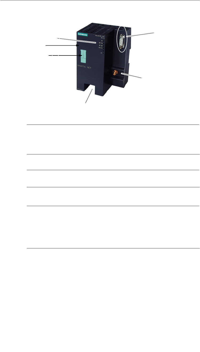
1 Construction
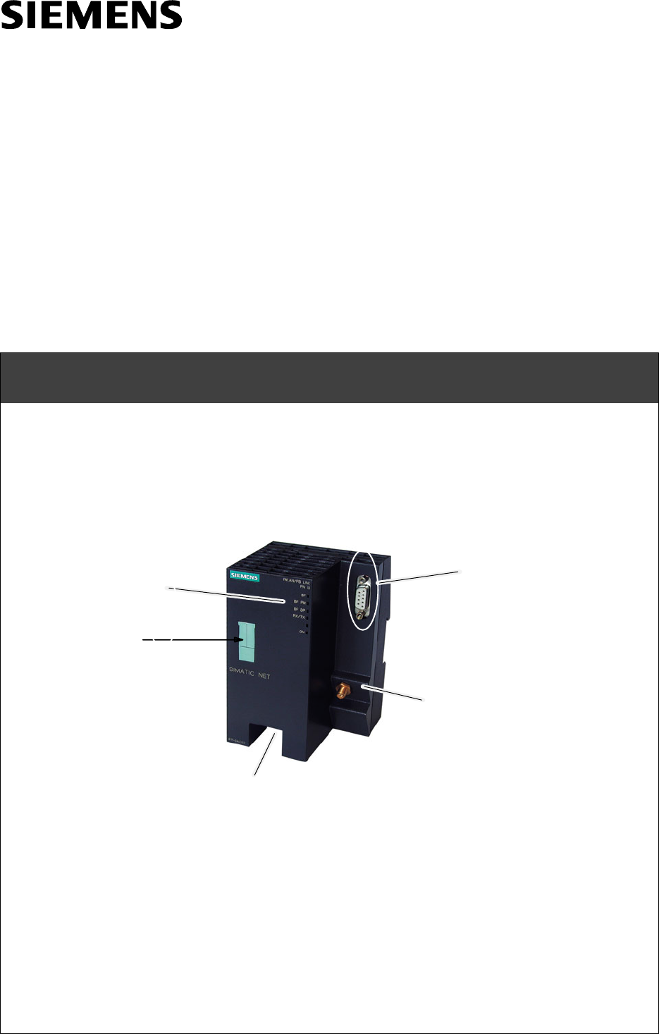
LED displays
Attachment to PROFIBUS:
9-pin D-sub female
connector
C-PLUG
Antenna:
Attachment to Ind. Wireless
LAN
Power supply
Reset button
Figure 1-1
The housing of the IWLAN/PB Link PN IO corresponds to that of the Power Rail
Booster. It is clipped onto a 15 mm or 7.5 mm standard mounting rail.
Either an antenna for RCoax or an antenna for an IWLAN wireless link is attached
over a connector. With degree of protection IP20, the IWLAN/PB Link PN IO is
suitable for installation in a cabinet.
The connectors and display elements are located exclusively on the front panel,
the optional C-PLUG is located behind a cover also on the front panel.
Other design features:
SNo fan necessary
SR-SMA interface for connecting antennas;
S9-pin D-sub female connector for attaching the IWLAN/PB Link PNIO to
PROFIBUS
S4-pin terminal block for connecting a redundant external DC 24 V power
supply;
SLED displays
Notice
If you replace the C-PLUG, make sure that the power supply is off!
2 Installation and Commissioning
5
IWLAN/PB Link PN IO Gateway for Industrial Ethernet / Manual Part B9
Release 1/2005
C79000-G8976-C200-01_vorabversion_01
2 Installation and Commissioning
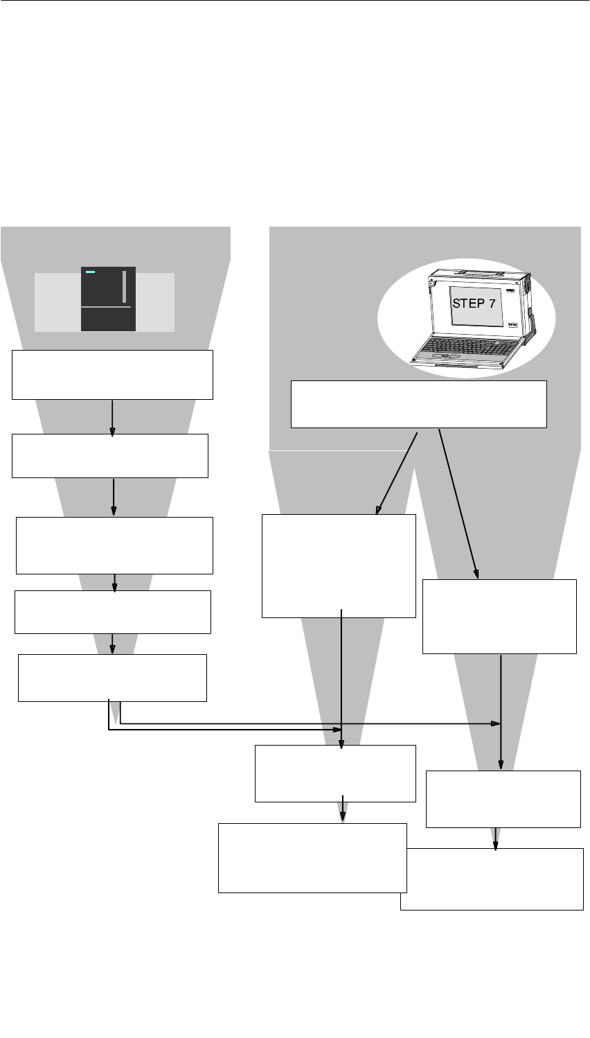
2.1 How to...
Follow the steps as shown in the graphic below; please make sure you read the
supplementary notes in this section. Installation and configuration can initially be
considered as independent procedures.
Install the IWLAN/PB Link PN IO
on a standard mounting rail
Connect to the power supply.
Connect the device to
PROFIBUS and to the WLAN
over the antenna.
Install the SIMATIC STEP 7
configuration software on a PG/PC.
Configure the
IWLAN/PB Link PN IO as
an S7-300 station with
HW Config.
Switch the power supply on.
Download the database
(configuration) from STEP 7 to
the IWLAN/PB Link PN IO.
Configuration: (see also Chapter 4):Installation:
Assign an IP address to
the IWLAN/PB Link PN
IO.
Configure the IWLAN/PB
Link PN IO as an IO
device in a PN IO system
(proxy with attached DP
master system)
Use as a gateway
only
See Section 4.1
Use as a PROFINET IO
device and as gateway
See Section 4.2
Download or update the
database (configuration) of the
corresponding PROFINET IO
controller
Assign a device name to
the IWLAN/PB Link PN IO.
Insert the PRESET PLUG.
2 Installation and Commissioning
6IWLAN/PB Link PN IO Gateway for Industrial Ethernet / Manual Part B9
Release 1/2005
C79000-G8976-C200-01_vorabversion_01
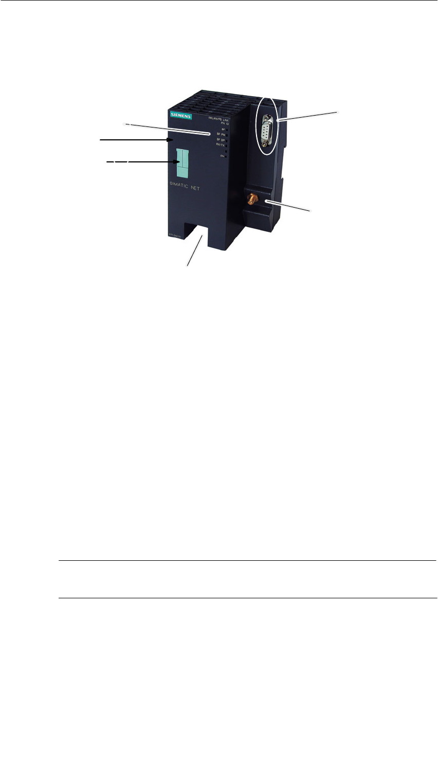
LED displays
Attachment to PROFIBUS:
9-pin D-sub female
connector
C-PLUG
Antenna:
Attachment to Ind. Wireless
LAN
Power supply
Reset button
Figure 2-1
Notice
Important notes on installation and operation:
SThe module must be installed so that its upper and lower ventilation slits are
not covered, allowing adequate ventilation.
Note
You can connect to PROFIBUS even with the power switched on.
Note
The requirements of EN61000-4-5, surge test on power supply lines, are met only
when using a Blitzductor VT AD 24V type no. 918 402 .
Manufacturer:
DEHN+SÖHNE GmbH+Co.KG Hans Dehn Str.1 Postfach 1640 D-92306
Neumarkt, Germany

2 Installation and Commissioning
7
IWLAN/PB Link PN IO Gateway for Industrial Ethernet / Manual Part B9
Release 1/2005
C79000-G8976-C200-01_vorabversion_01
!Warning
The IWLAN/PB Link PN IO product must be installed in an enclosure or
switchgear cabinet.
Where ATEX 100a (EN 50021) applies, this enclosure must meet at least IP54 in
compliance with EN 60529.
WARNING
THE DEVICE MAY ONLY BE CONNECTED TO THE POWER SUPPLY OR
DISCONNECTED FROM IT WHEN THE RISK OF EXPLOSION CAN BE
EXCLUDED WITH CERTAINTY.

2 Installation and Commissioning
8IWLAN/PB Link PN IO Gateway for Industrial Ethernet / Manual Part B9
Release 1/2005
C79000-G8976-C200-01_vorabversion_01
Ground/Chassis Ground Concept
The device is grounded over the mounting rail.
PG/PC Connection
You can connect the PG when configuring the CP as follows:
Sover Industrial Wireless LAN (recommended)
You can only configure the IWLAN/PB Link PN IO over wireless LAN after it has
been assigned its IP address. Please follow the instructions for initial
addressing in Section 4.
Sover PROFIBUS
You can only configure the IWLAN/PB Link PN IO over PROFIBUS after it has
been assigned its PROFIBUS address. Please follow the instructions for
addressing in Section 4.
Module Accessories
The accessories required to connect the IWLAN/PB Link PN IO to a wireless LAN
and PROFIBUS LAN (power supply) must be ordered separately.
The optional C-PLUG can also be ordered separately.
For more detailed information and ordering data, refer to the Catalog IK PI.
2 Installation and Commissioning
9
IWLAN/PB Link PN IO Gateway for Industrial Ethernet / Manual Part B9
Release 1/2005
C79000-G8976-C200-01_vorabversion_01
2.1.1 Power Supply
!Warning
The IWLAN/PB Link PN IO is designed for operation with safety extra-low voltage
(SELV). This means that only safety extra-low voltages (SELV) complying with
IEC950/EN60950/ VDE0805 may be connected to the power supply terminals.
The power supply unit to supply the IWLAN/PB Link PN IO must comply with NEC
Class 2 (voltage range 20.4 - 28.8 V, current requirement 300 mA).
The device must only be supplied by a power supply unit that complies with the
requirements of class 2 for power supply units ”National Electrical Code, Table 11
(b)”. If the power supply is installed redundantly (two separate power supplies), the
total power of both power supplies together must meet these requirements.
Exceptions:
SSupply with PELV (complying with VDE 0100-410) is also permitted as long as
the generated rated voltage does not exceed the voltage limits 25 V AC or 60 V
DC.
SSupply by a SELV power source (complying with IEC 60950) or PELV power
source (complying with VDE 0100-410) without restricted power is also
permitted as long as suitable fire prevention measures are taken by:
- installing in cabinet or suitable enclosure
- installing in suitably equipped, closed room
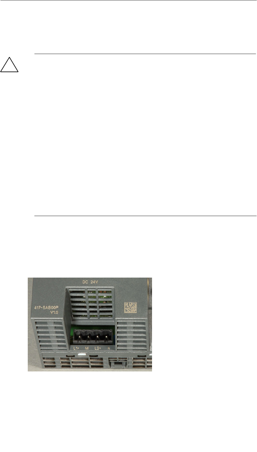
The power supply is connected over a 4-pin plug-in terminal block. The power
supply can be connected redundantly. The two inputs are isolated. There is no load
sharing. When the supply is redundant, the power source with the higher output
voltage supplies the IWLAN/PB Link PN IO alone. The power supply is connected
to the housing over a high resistance to allow ungrounded installation.
L1+: +24 V DC
M: Chassis 24 V DC
L2+: +24 V DC
M: Chassis 24 V DC
Figure 2-2 Power Supply
2 Installation and Commissioning
10 IWLAN/PB Link PN IO Gateway for Industrial Ethernet / Manual Part B9
Release 1/2005
C79000-G8976-C200-01_vorabversion_01
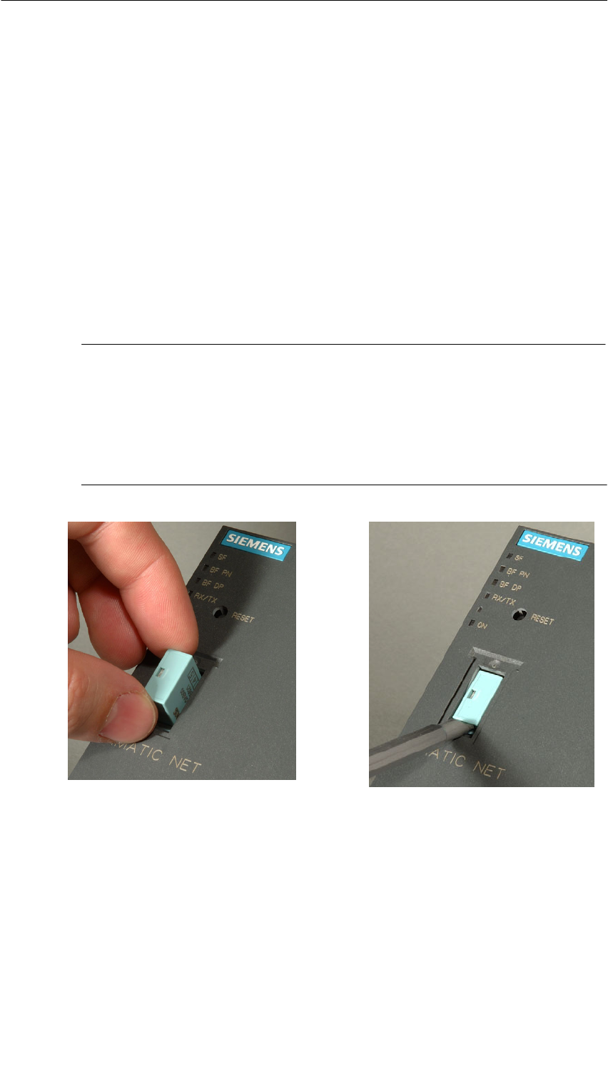
2.2 C-PLUG (Configuration Plug)
C-Plug Removable Memory Medium As an Alternative to Flash Memory
The IWLAN/PB Link PN IO has an internal flash memory for storage of the project
engineering data. As an option, the device can be operated with a C-PLUG
(configuration plug) removable memory medium.
The IWLAN/PB Link PN IO can be operated with or without a C-PLUG. The
existing flash memory is then only used when no C-PLUG is inserted.
If a C-PLUG is inserted, the project engineering data is always stored on it. This
simplifies replacement of modules. By simply exchanging the C-PLUG, all the data
can be transferred to the replacement module.
Notice
SIf a C-PLUG is inserted, that does not contain valid formatting or no valid data
for the IWLAN/PB Link PN IO will not start up! Device status: “STOP with
error”.
In this case, you must reformat the C-PLUG (with NCM diagnostics) or replace
it with a C-PLUG containing valid data.
SThe C-PLUG may only be inserted for removed when the power is turned off!
Figure 2-3 Fitting a C-PLUG in the IWLAN/PB Link PN IO and Removing a C-PLUG from the IE/PB Link
PN IO using a Screwdriver

3 FCC Approval
11
IWLAN/PB Link PN IO Gateway for Industrial Ethernet / Manual Part B9
Release 1/2005
C79000-G8976-C200-01_vorabversion_01
3 FCC Approval
This device complies with Part 15 of the FCC Rules and with RSS-210 of Industry
Canada.
Operation is subject to the following two conditions:
1. this device my not cause harmful interference, and
2. this device must accept any interference received, including interference that
may cause undesired operation.
Notice
Changes or modifications made to this equipment not expressly approved by
SIEMENS may void the FCC authorization to operate this equipment.
This equipment has been tested and found to comply with the limits for a Class B
digital device, pursuant to Part 15 of the FCC Rules. These limits are designed to
provide reasonable protection against harmful interference in a residential
installation. This equipment generates, uses and can radiate radio frequency
energy and, if not installed and used in accordance with the instructions, may
cause harmful interference to radio communications. However, there is no
guarantee that interference will not occur in a particular installation. If this
equipment does cause harmful interference to radio or television reception, which
can be determined by turning the equipment off and on, the user is encouraged to
try to correct the interference by one or more of the following measures:
SReorient or relocate the receiving antenna.
SIncrease the separation between the equipment and receiver.
SConnect the equipment into an outlet on a circuit different from that to which the
receiver is connected.
Consult the dealer or an experienced radio/TV technician for help.
Notice
FCC Radiation Exposure Statement:
This equipment complies with FCC radiation exposure limits set forth for an
uncontrolled environment. This equipment should be installed and operated with
minimum distance of 20cm between the radiator and your body.
This transmitter must not be co-located or operating in conjunction with any other
antenna or transmitter.

4 Technical Specifications
12 IWLAN/PB Link PN IO Gateway for Industrial Ethernet / Manual Part B9
Release 1/2005
C79000-G8976-C200-01_vorabversion_01
4 Technical Specifications
Data transmission / supported
transmission rate
STransmission rate wireless
SSupported standards wireless
1 to 54 Mbps
802.11a, 802.11b, 802.11g
SPROFIBUS 9.6 Kbps, 19.2 Kbps, 45.45 Kbps, 93.75 Kbps
187.5 Kbps, 500 Kbps, 1.5 Mbps, 3 Mbps
6 Mbps, 12 Mbps
Maximum current consumption on the
PROFIBUS interface with network
components connected (for example,
optical network components)
100 mA at 5V
Interfaces
Industrial wireless LAN
Attachment to PROFIBUS
R-SMA antenna sockets
9-pin D-sub female connector
Power supply 2 inputs for
DC +20.4 V to 28.8 V
The power supply is electrically isolated; there is a
high-resistance connection (>700 kΩ) with contact springs for
mounting the housing on the rail).
Current consumption
Sfrom external 24 V DC Approx. 0.3 A (typical at 24 V)
Power loss 6.5 W
Permitted ambient conditions
SOperating temperature
STransportation/storage
temperature
SRelative humidity max.
SAltitude
0 °C to +60 °C
-40 °C to +70 °C
95% at +25 °C
up to 2000 m above sea level
Design
Module format:
SDimensions (W x H x D) in mm
SWeight approx.
Compact module
90 x 132 x 75
300 g
In addition to this, all the information in /1/ S7-300 Module Data: Reference
Manual in the section ”General Technical Specification” on the topics listed below
applies to the IWLAN/PB Link PN IO
SElectromagnetic compatibility
STransportation and storage conditions
SMechanical and climatic ambient conditions
SInsulation tests, class of protection and degree of protection
Exception: The dimensions of the module and installation do not match the
information relating to the SIMATIC S7-300.