Siemens MD720-3 GSM/GPRS Modem User Manual SINAUT MD720 3
Siemens AG GSM/GPRS Modem SINAUT MD720 3
UserManual.wiki
>
Siemens
>
MD720 3 User Manual
Manual
Navigation menu
Upload a User Manual
Namespaces
Wiki Guide
HTML
PDF
Info
Views
User Manual
Discussion / Help
Navigation
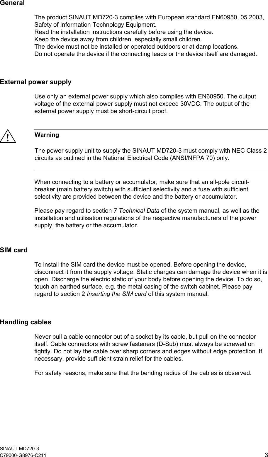
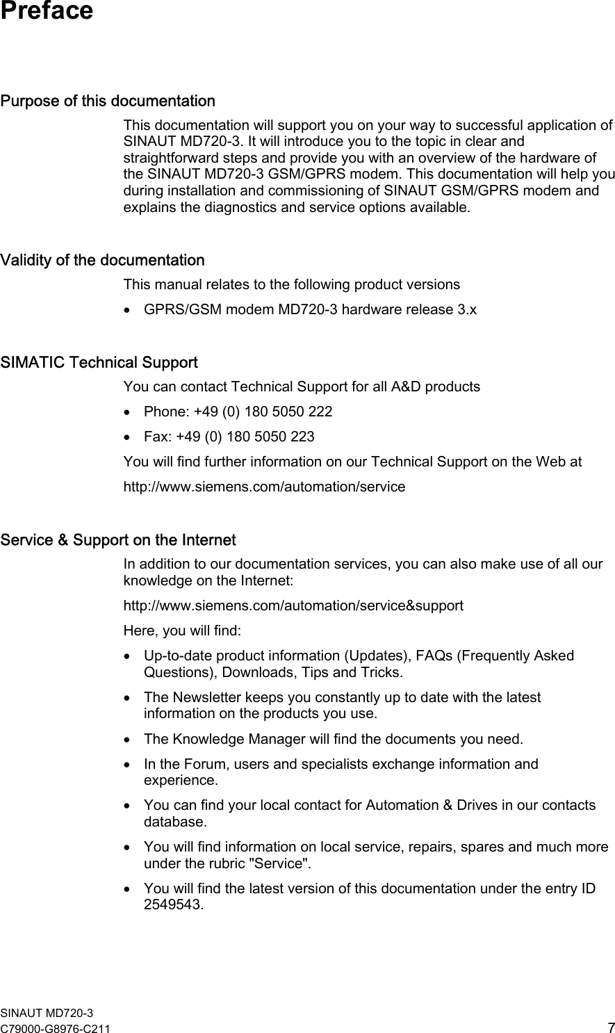


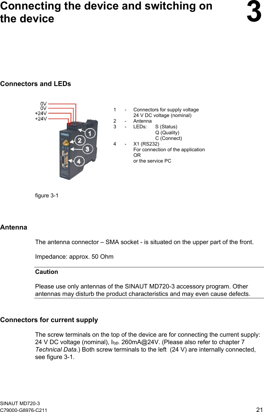

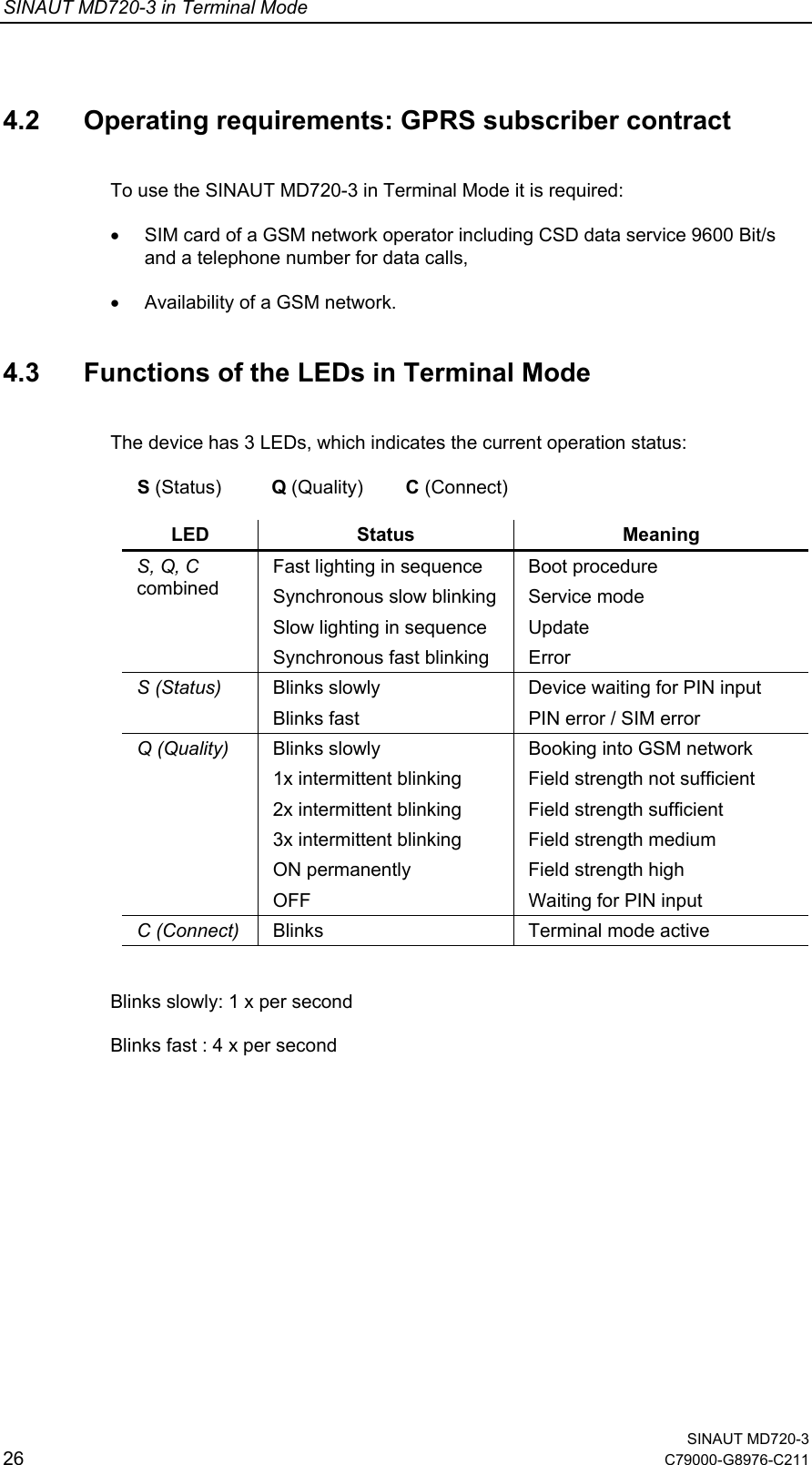
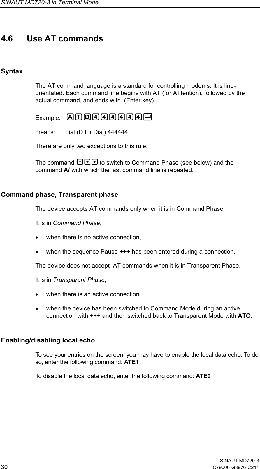
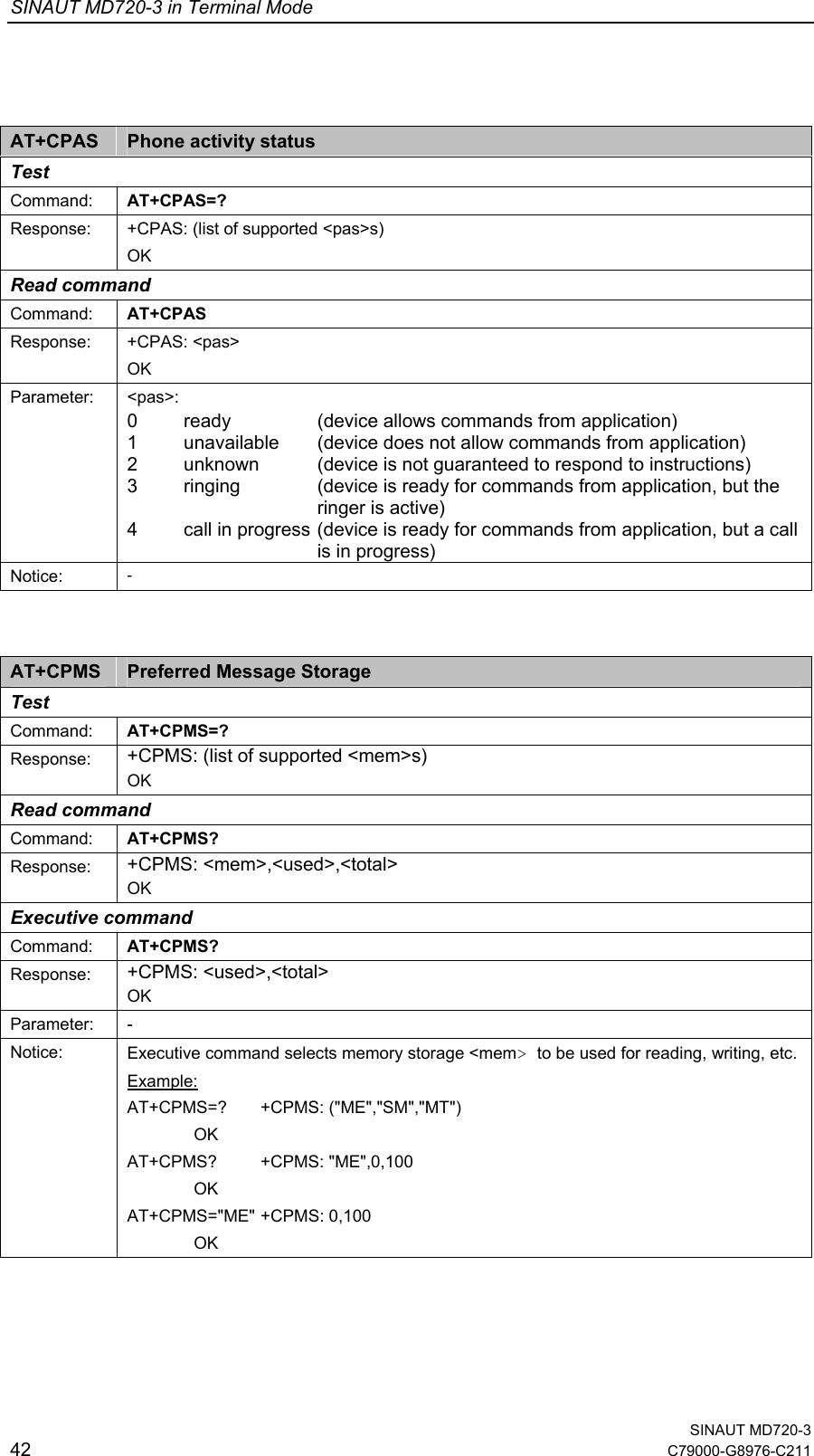
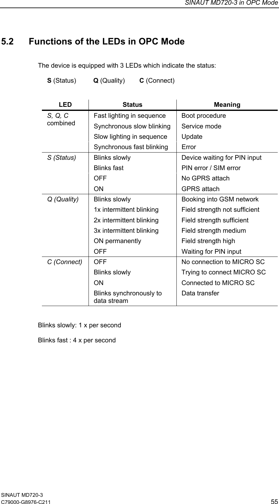
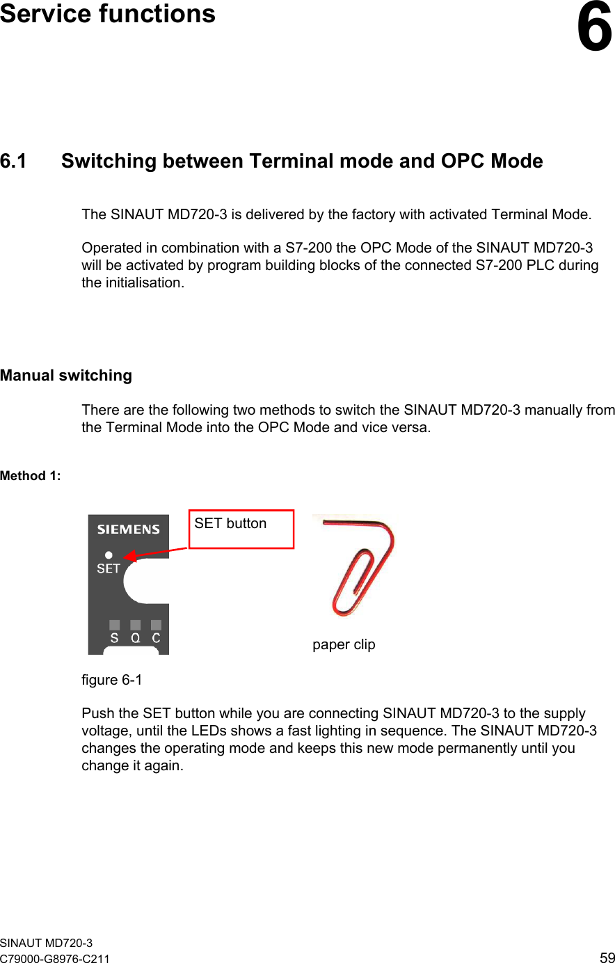
![SINAUT MD720-3 in Terminal Mode SINAUT MD720-3 32 C79000-G8976-C211 4.7 Supported AT commands in Terminal Mode All AT commands being not listed below, will be answered with OK by the device, but the command will not be executed. +++ Switch from data mode to command mode Execute command Command: +++ Response: This command is only available during data calls. The +++ characters sequence causes to cancel de data flow over the AT interface and switch to command mode. This allows to enter AT commands while maintaining the data connection to the remote device. Parameter: - Notice: To return to data mode, use the ATO command Line does not need to end with terminating character, i.e. <CR><LF> A/ Repeat previous command line Executive command Command: A/ Response: Depend on the previous command Parameter: - Notice: Line does not need to end with terminating character, i.e. <CR><LF> ATA Answer a call Executive command Command: ATA Response: CONNECT[<text>] Data Connexion established OK Voice Connexion established or if cancellation of the command NO CARRIER Response if no connection Parameter: - Notice: See ATX for setup of the CONNECT message.](https://usermanual.wiki/Siemens/MD720-3/User-Guide-626516-Page-32.png)
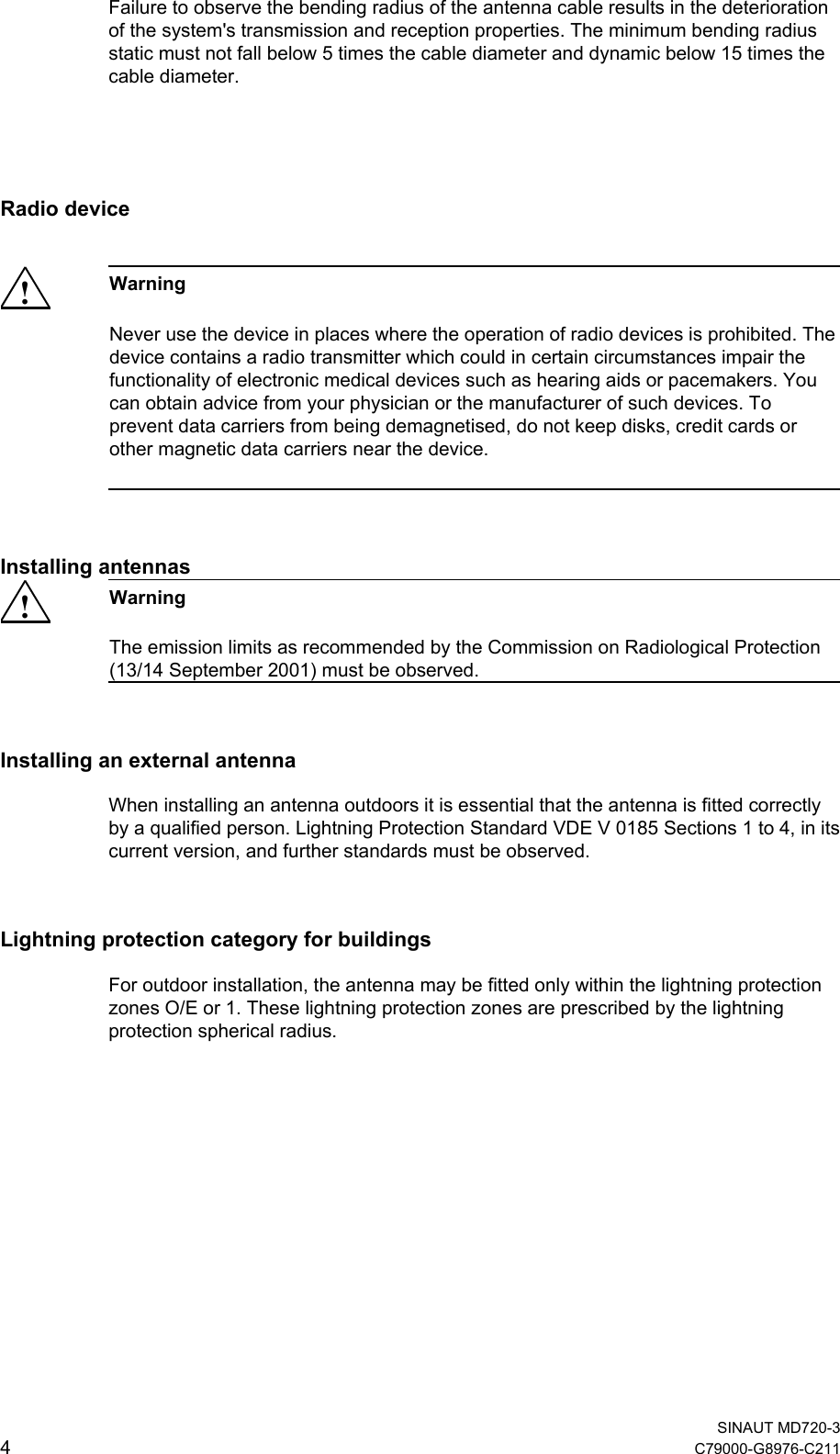
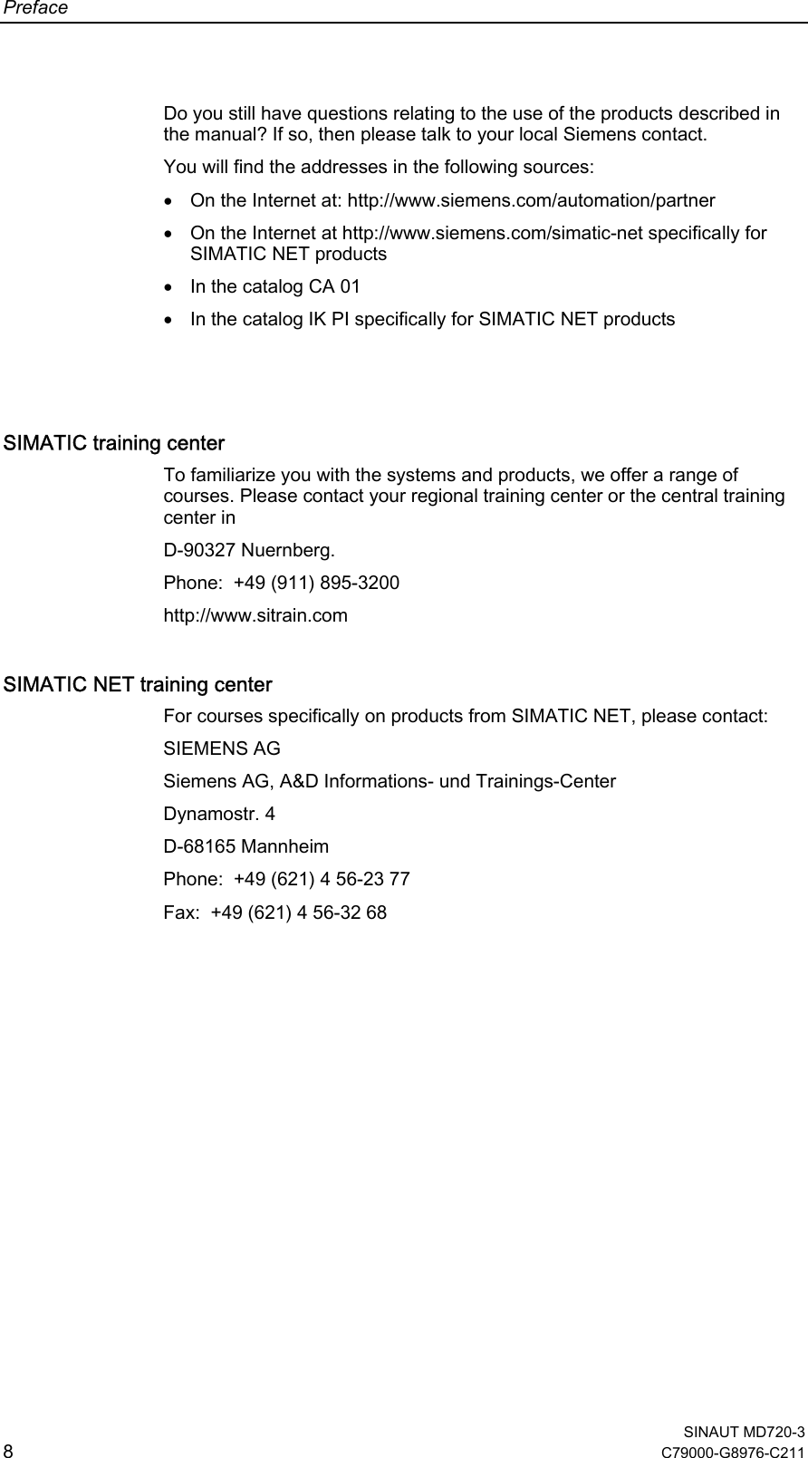
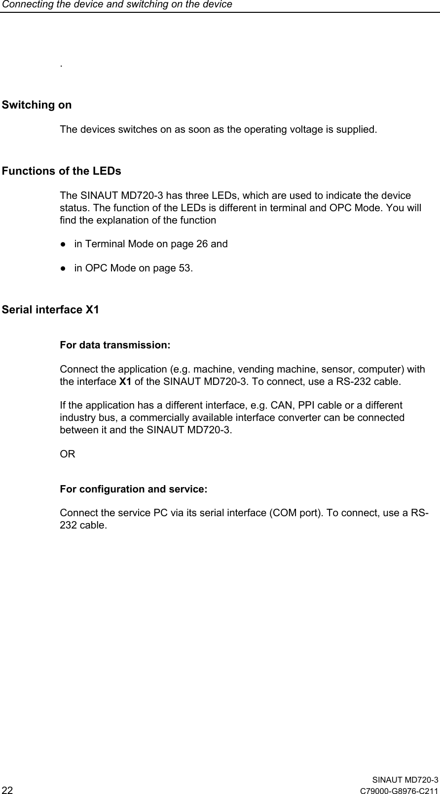
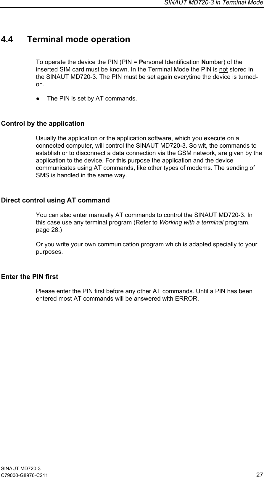
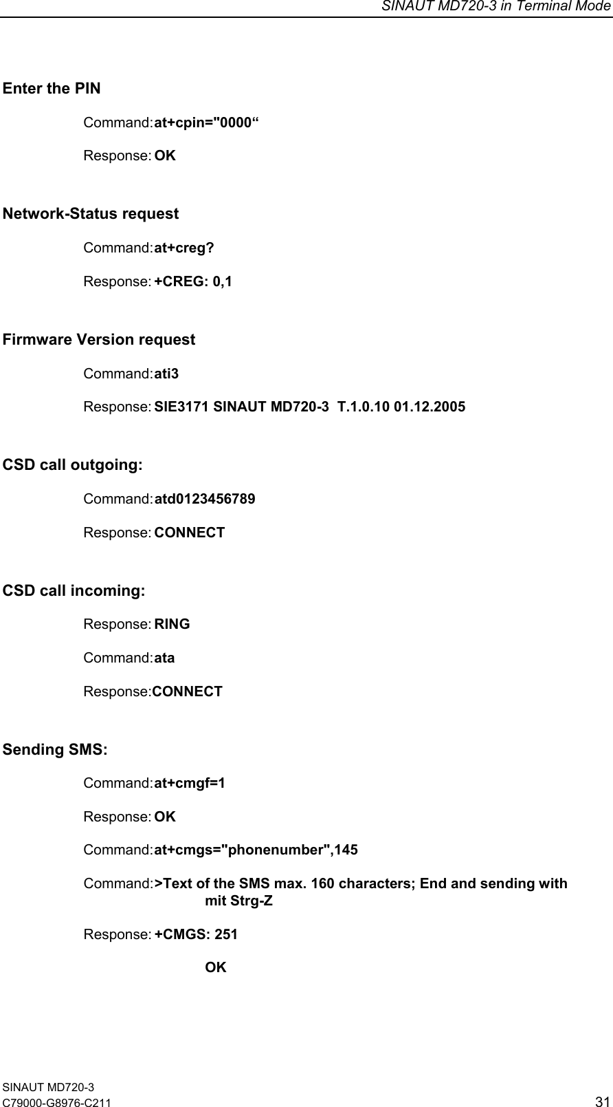
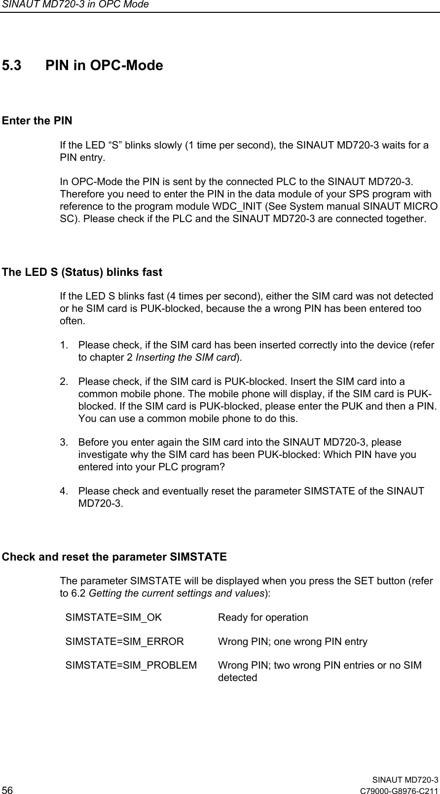
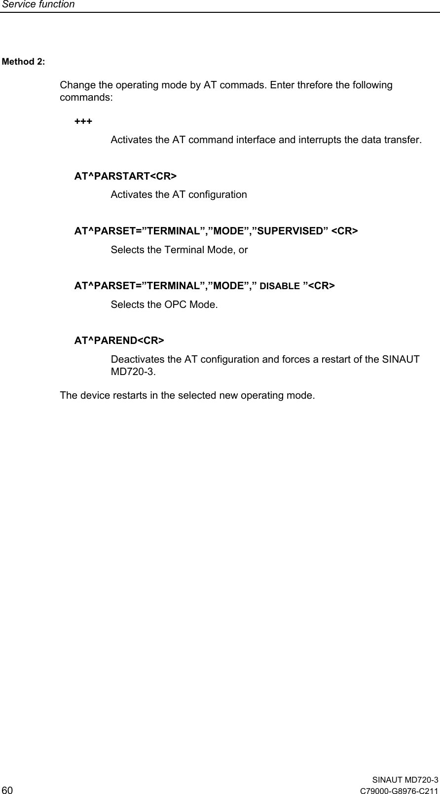
![SINAUT MD720-3 in Terminal Mode SINAUT MD720-3 C79000-G8976-C211 33 ATD Mobile originated Call to dial a number Executive command Command: ATD[<n>] Response: The connection cannot be established: NO DIALTONE BUSY NO CARRIER NO ANSWER Data connection successfully connected: CONNECT[<text>] Parameter: <n>: String of dialing digits and optionally V.25ter modifiers (dialing digits): 0-9, * , #, +, A, B, C Notice: - ATE Local Echo On/Off Executive command Command: ATE[<value>] Response: OK Parameter: <value> : 0 Local Echo off 1 Local Echo on <Default> Notice: This setting determines whether or not the device echoes characters received from application during command state ATH Disconnect existing connection Executive command Command: ATH Response: OK Parameter: - Notice: On this command, all calls in progress are ended](https://usermanual.wiki/Siemens/MD720-3/User-Guide-626516-Page-33.png)
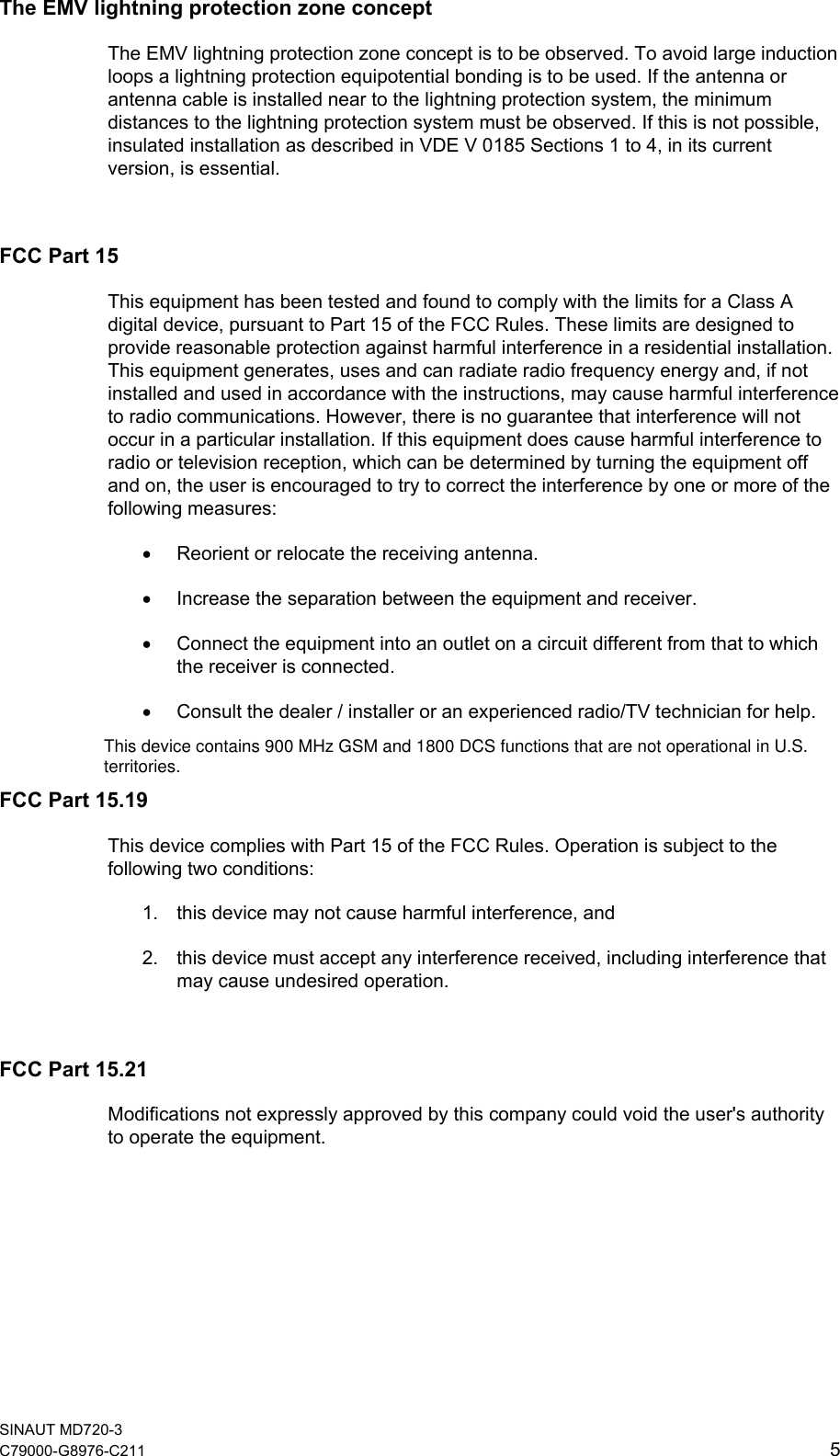
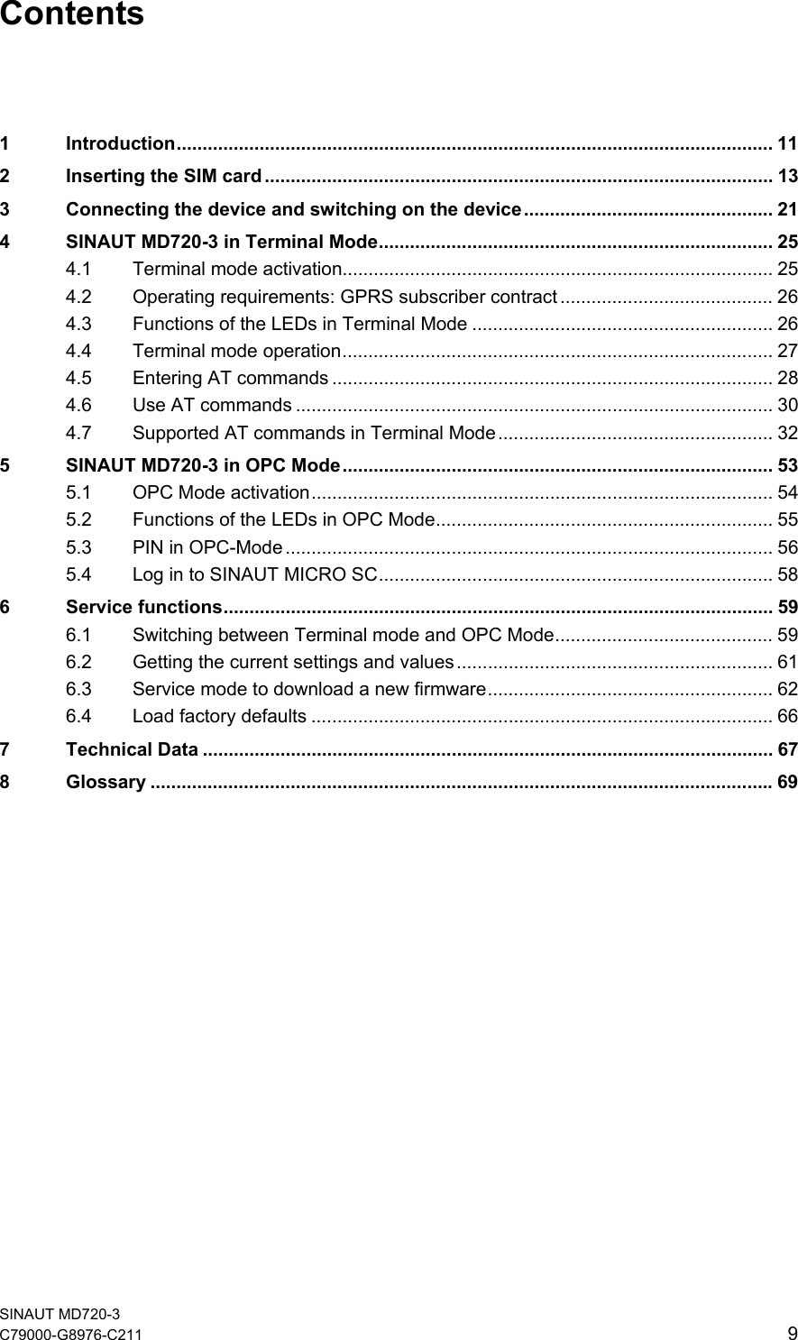
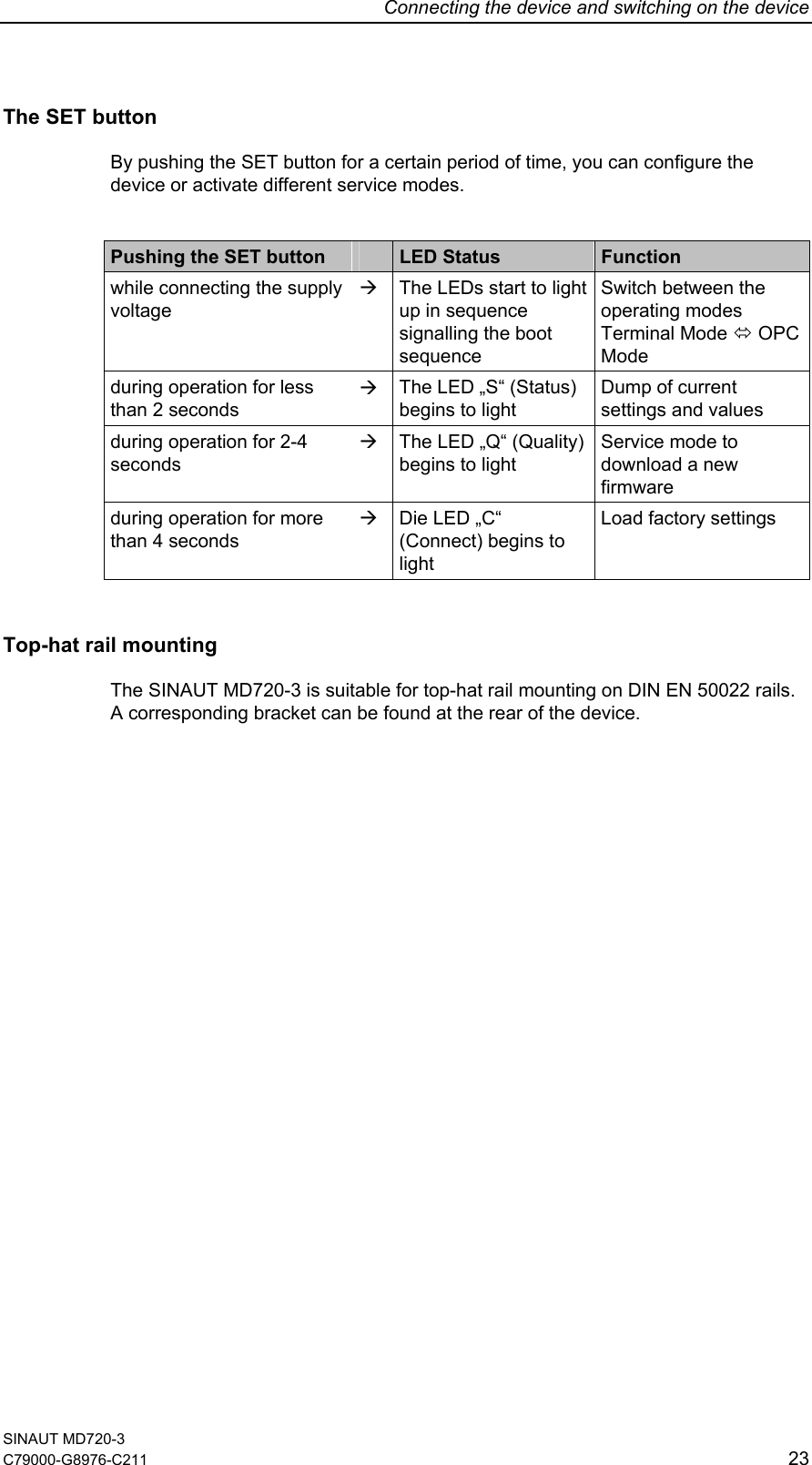
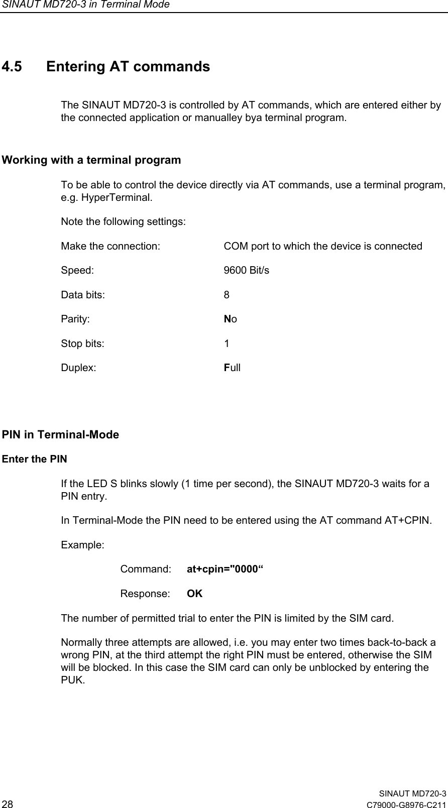
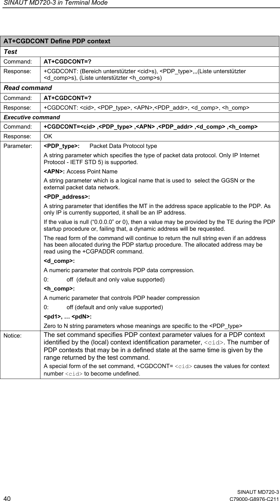
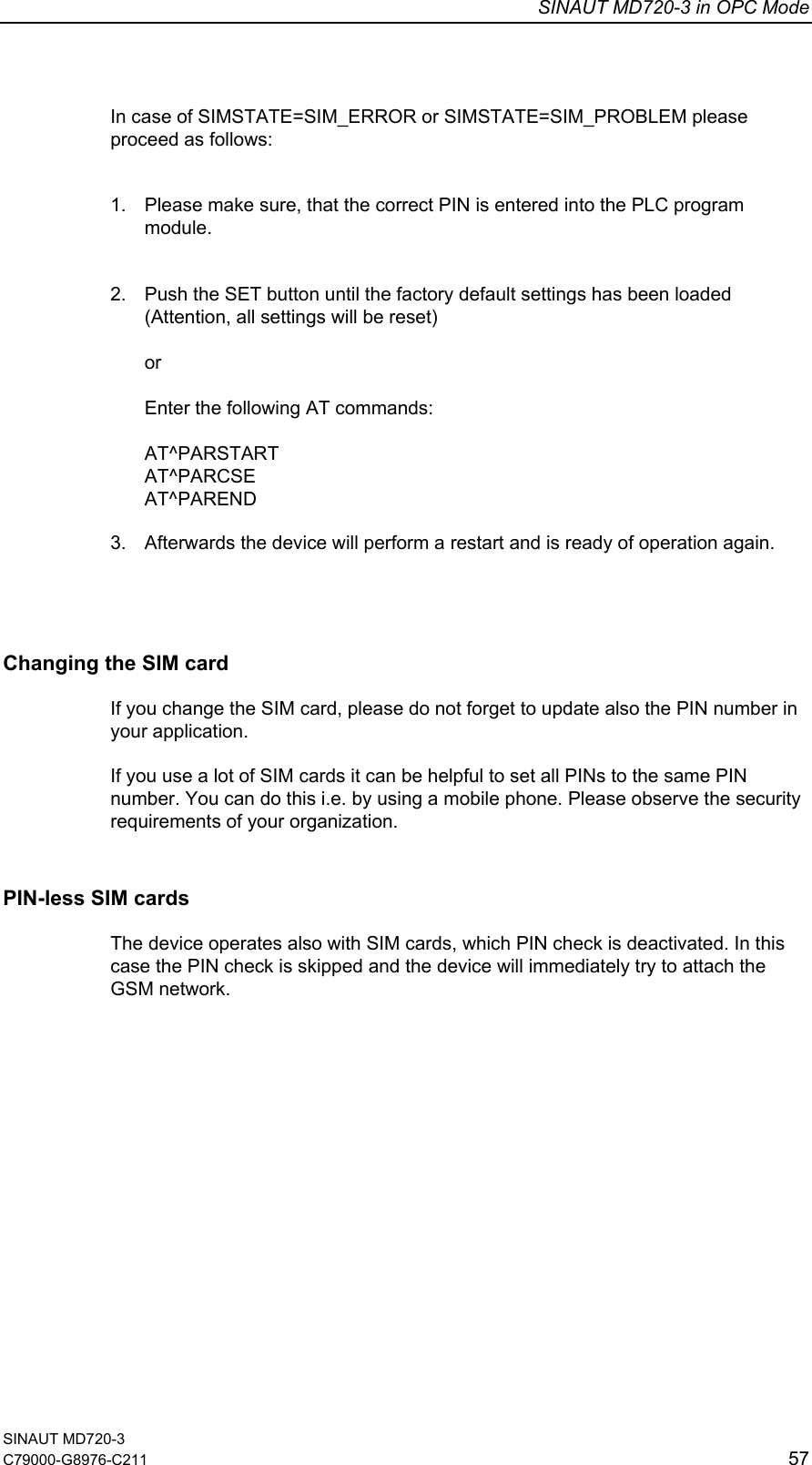
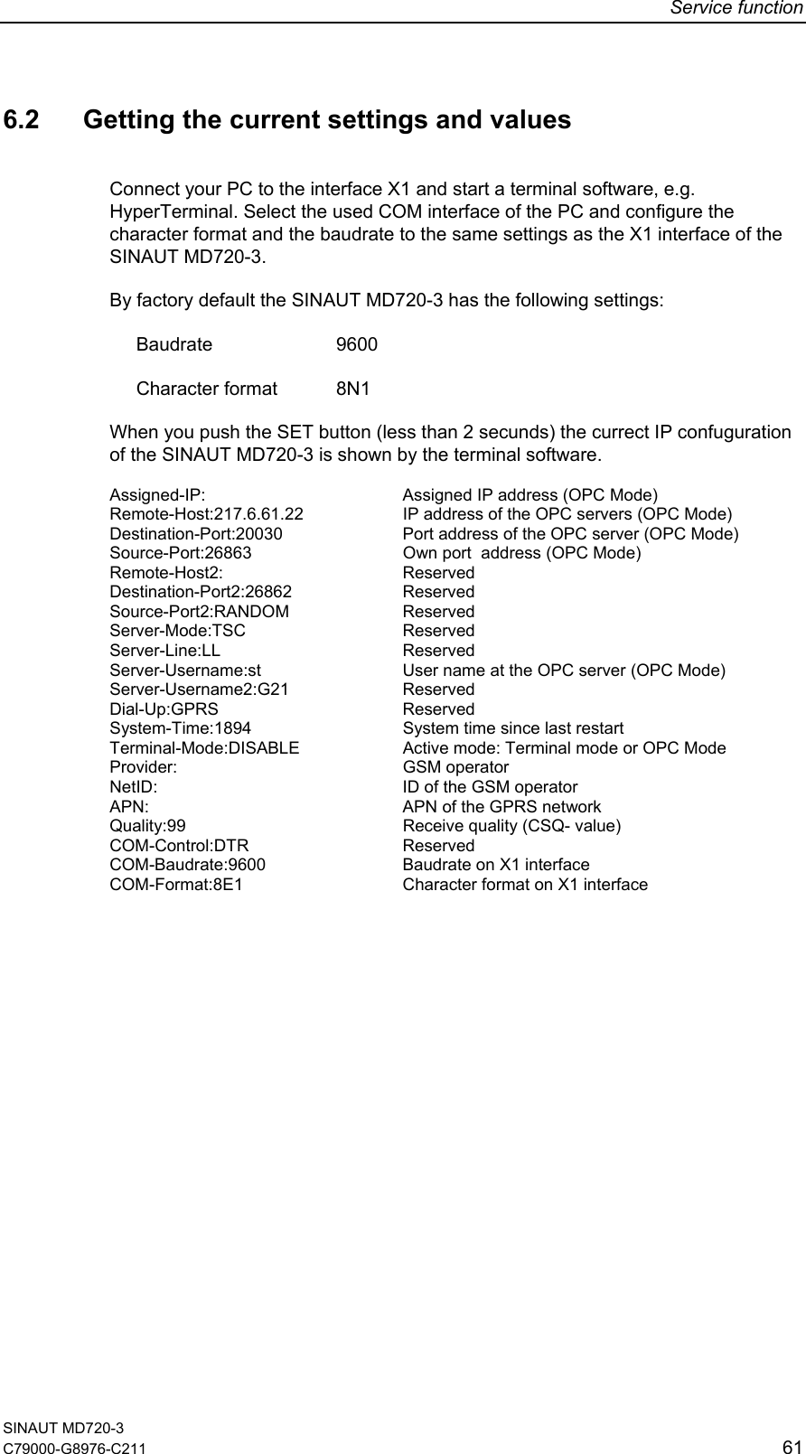
![SINAUT MD720-3 in Terminal Mode SINAUT MD720-3 34 C79000-G8976-C211 ATI Request identification information Read command Command: ATI[<value>] Response: <text> (depends on <value>) OK Parameter: <value> : none: Product name and Firmware Version 0: Product name 1: Product name and Firmware Version 3: Product name and Firmware Version Notice: <text> may take more than one line ATO Switch from command mode to data mode Executive command Command: ATO[n] Response: Device returns to data mode from command mode: CONNECT <text> If connection is not successfully resumed NO CARRIER Parameter: <n> 0 switch from command mode to data mode Notice: ATO corresponds to the +++ escape sequence. ATQ Set result code presentation mode Executive command Command: ATQ[<n>] Response: OK (if <n> = 0) Nothing (if <n> = 1) Parameter: <n> 0: result codes transmitted by TA <Default> 1: no result code transmitted by TA Notice: Specifies whether or not the device transmits any result code to the application. Information text transmitted in response is not affected by this setting. ATS0? Shows Automatic answering settings Read command Command: ATS0? Response: <n> OK Parameter: See ATS0=<n> Notice: -](https://usermanual.wiki/Siemens/MD720-3/User-Guide-626516-Page-34.png)
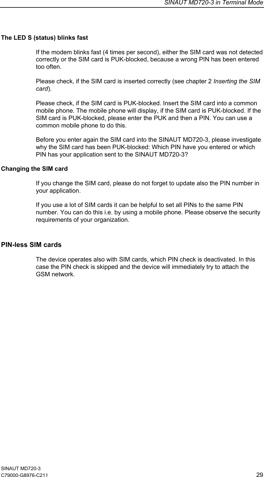
![SINAUT MD720-3 in Terminal Mode SINAUT MD720-3 C79000-G8976-C211 35 ATS0 Configures Automatic answering Executive command Command: ATS0=<n> Response: OK Parameter: <n>: 0: automatic answering deactivated <Default> 1-255: number of rings before automatically answering Notice: - ATV Set result code format mode Executive command Command: ATV[<value>] Response: 0 When numeric mode is activated OK When verbose mode is activated Parameter: <value> : 0 Information <text><CR><LF> Result Code (short format): <numeric code><CR> 1 Information <CR><LF><text><CR><LF> Result Code (long format): <CR><LF><verbose code><CR> <Default> Notice: This parameter setting determines the contents of the header and trailer transmitted with result codes and information responses](https://usermanual.wiki/Siemens/MD720-3/User-Guide-626516-Page-35.png)
![SINAUT MD720-3 in Terminal Mode SINAUT MD720-3 36 C79000-G8976-C211 ATX Set CONNECT result code Format und Call monitoring Executive command Command: ATX[<value>] Response: OK Parameter: <value>: 0 : CONNECT result code only returned, dial tone and busy detection are both disabled <Default> 1 : CONNECT<text> result code only returned, dial tone and busy detection are both disabled 2 : same as 1 3 : same as 1 4 : same as 1 Notice: Result codes numeric or verbose: OK 0 Command executed, no error, Restart executed CONNECT 1 Connection established RING 2 Ring detected NO CARRIER 3 Connection not established or interrupted ERROR 4 Command not valid NO DIALTONE 6 No dialtone, dialling not possible, wrong mode BUSY 7 Remote station busy CONNECT 2400/RLP 1 Connect at 2400 bps and Radio Link Protocol CONNECT 4800/RLP 1 Connect at 4800 bps and Radio Link Protocol CONNECT 9600/RLP 1 Connect at 9600 bps and Radio Link Protocol AT&C AT&C Set circuit Data Carrier Detect (DCD) function mode Executive command Command: AT&C[<value>] Response: OK Parameter: <value> 0 : DCD line is always ON 1 : DCD line is ON in the presence of data carrier only. <Default> Notice: - AT&D Set circuit Data Terminal Ready (DTR) function mode Executive command Command: AT&D[<value>] Response: OK Parameter: <value>: 0: Device ignores status on DTR. <Default> 2: ON->OFF on DTR: Disconnect call, change to command mode. During state DTR = OFF is auto-answer off. Notice: -](https://usermanual.wiki/Siemens/MD720-3/User-Guide-626516-Page-36.png)
![SINAUT MD720-3 in Terminal Mode SINAUT MD720-3 C79000-G8976-C211 37 AT&F Restore manufactory configuration Executive command Command: AT&F Response: OK Parameter: <value>: 0: Restore parameters to manufactory values Notice: Restore configuration of manufacturer. AT&W Save stored profile Executive command Command: AT&W<n> Response: OK Parameter: <n> Ohne Speicherung in Profil 0 0 Speicherung in Profil 0 Notice: This commands saves the current configuration in a non volatile memory. See also AT&V. AT&V Display current configuration Executive command Command: AT&V[<value>] Response: ACTIVE PROFILE: <current configuration> OK Parameter: <value>: 0: only active profile Notice: The configuration is a text string on multiple lines as shown in the example below. As it is dependant on the manufactory and user setup, it is impossible to list the exact number of information given](https://usermanual.wiki/Siemens/MD720-3/User-Guide-626516-Page-37.png)
![SINAUT MD720-3 in Terminal Mode SINAUT MD720-3 38 C79000-G8976-C211 AT+CPIN Enter PIN Test Command: AT+CPIN=? Response: OK Read command Command: AT+CPIN? Response: +CPIN: <code> Executive command Command: AT+CPIN=<pin> [,<newpin>] Response: OK Parameter: <code>: Values reserved by this device: READY Device is not pending for any password SIM PIN Device is waiting SIM PIN to be given SIM PUK Device is waiting SIM PUK to be given. Also, a second pin, <newpin>, is used to replace the old pin in the SIM and should thus be supplied SIM PIN2 Device is waiting SIM PIN2 to be given (this <code> is recommended to be returned only when the last executed command resulted in PIN2 authentication failure (i.e. +CME ERROR: 17); if PIN2 is not entered right after the failure, it is recommended that ME does not block its operation) SIM PUK2 Device is waiting SIM PUK2 to be given (this <code> is recommended to be returned only when the last executed command resulted in PUK2 authentication failure (i.e. +CME ERROR: 18); if PUK2 and new PIN2 are not entered right after the failure, it is recommended that ME does not block its operation). Also, a second pin, <newpin>, is used to replace the old pin in the SIM and should thus be supplied PH-NET PIN ME is waiting personalization password to be given <pin>, <newpin>: string type value (8 characters max.) Notice: -](https://usermanual.wiki/Siemens/MD720-3/User-Guide-626516-Page-38.png)
![SINAUT MD720-3 in Terminal Mode SINAUT MD720-3 C79000-G8976-C211 39 AT+CSQ Check Signal Quality Test Command: AT+CSQ=? Response: +CSQ: (list of supported <rssi>s),(list of supported <ber>s) OK Response: Command: AT+CSQ Response: +CSQ: <rssi>,<ber> OK Parameter: <rssi>: 0 -113 dBm or less 1 -111 dBm 2...30 -109... -53 dBm 31 -51 dBm or greater 99 not known or not detectable <ber> (in percent) 0...7 as RXQUAL values in the table in GSM 05.08 [20] subclause 8.2.4 99 not known or not detectable Notice: The read command (AT+CSQ?) returns an error. AT+CGSN Request product serial number identification (IMEI) identical to GSN Test Command: AT+CGSN=? Response: OK Read command Command: AT+CGSN Response: <sn> (identification text for determination of the individual device) OK Parameter: - Notice: -](https://usermanual.wiki/Siemens/MD720-3/User-Guide-626516-Page-39.png)
![SINAUT MD720-3 in Terminal Mode SINAUT MD720-3 C79000-G8976-C211 43 AT+CNUM Subscriber number Test Command: AT+CNUM=? Response: OK Executive command Command: AT+CNUM Response: +CNUM: [<alpha1>],<number1>,<type1>[,<speed>,<service>[,<itc>]] [<CR><LF>+CNUM: [<alpha2>],<number2>,<type2>[,<speed>,<service> [,<itc>]] [...]] OK Parameter: <alpha>: optional alphanumeric string associated with <number>; used character set should be the one selected with command Select TE Character Set +CSCS <number>: string type phone number of format specified by <type> <type>: type of address octet in integer format (refer GSM 04.08 [8] subclause 10.5.4.7) <speed>: <service>: service related to the phone number 0: asynchronous modem 1: synchronous modem 2: PAD Access (asynchronous) 3: Packet Access (synchronous) 4: voice 5: fax also all other values below 128 are reserved by the present document <itc>: information transfer capability 0: 3.1kHz 1: UDI Notice: Action command returns the MSISDNs related to the subscriber (this information can be stored in the SIM or in the ME) The Read Command (AT+CNUM?) returns an error Example: AT+CNUM +CNUM: "TEL","0612345678",129 +CNUM: "","",255 +CNUM: "","",255 +CNUM: "","",255 OK](https://usermanual.wiki/Siemens/MD720-3/User-Guide-626516-Page-43.png)
![SINAUT MD720-3 in Terminal Mode SINAUT MD720-3 44 C79000-G8976-C211 AT+CBST Select bearer service type Read command Command: AT+CBST=? Response: +CBST: (list of supported <speed>s),(list of supported <name>s),(list of sup- ported <ce>s) OK Executive command Command: AT+CBST=[<speed> [,<name>[,<ce>]]] Response: OK Parameter: <speed>: 4 2400 bps (V.22bis) 6 4800 bps (V.32) 7 9600 bps (V.32) <Default> 68 2400 bps (V.110 or X.31 flag stuffing) 70 4800 bps (V.110 or X.31 flag stuffing) 71 9600 bps (V.110 or X.31 flag stuffing) <name>: 0 data circuit asynchronous (UDI or 3.1 kHz modem) <Default> 1 data circuit synchronous (UDI or 3.1 kHz modem) <ce>: 0 transparent 1 non-transparent <Default> Notice: Set command selects the bearer service <name> with data rate <speed>, and the connection element <ce> to be used when data calls are originated. AT+CMGD Delete a SMS Test Command: AT+CMGD=? Response: +CMS ERROR: <err> Read command Command: AT+CMGD? Response: +CMS ERROR: <err> Executive command Command: +CMGD=<index> Response: OK or +CMS ERROR: <err> Parameter: <index> 1 – n Memory location on the SIM card; n depends on the memory capacity of the SIM card <err> Error code Notice: -](https://usermanual.wiki/Siemens/MD720-3/User-Guide-626516-Page-44.png)
![SINAUT MD720-3 in Terminal Mode SINAUT MD720-3 C79000-G8976-C211 45 AT+CMGF Select SMS message format Test Command: AT+CMGF=? Response: +CMGF: (list of supported <mode>s) OK Read command Command: AT+CMGF? Response: +CMGF: <mode> OK Executive command Command: AT+CMGF=[<mode>] Response: OK Parameter: <mode>: 0 PDU mode <Default> 1 Text mode Notice: - AT+ CMGL List SMS messages from preferred store Test Command: AT+CMGL=? Response: +CMGL: (list of supported <stat>s) OK Executive command Command: AT+CMGL[=<stat>] Response: if PDU mode (+CMGF=0) and command successful: [+CMGL: <index>,<stat>,[<alpha>],<length><CR><LF><pdu> [<CR><LF>+CMGL:<index>,<stat>,[<alpha>],<length><CR><LF><pdu> [...]]] OK Parameter: - Notice: Execution command returns messages with status value <stat> from preferred message storage <mem1> . Entire data units <pdu> are returned.](https://usermanual.wiki/Siemens/MD720-3/User-Guide-626516-Page-45.png)
![SINAUT MD720-3 in Terminal Mode SINAUT MD720-3 46 C79000-G8976-C211 AT+CMGR Read SMS message Test Command: AT+CMGR=? Response: OK Executive command Command: AT+CMGR=<index> Response: if PDU mode (+CMGF=0) and command successful: +CMGR: <stat>,[<alpha>],<length><CR><LF><pdu> OK Parameter: - Notice: Execution command returns message with location value <index> from preferred message storage <mem1>. Status of the message and entire message data unit <pdu> is returned. If status of the message is 'received unread', status in the storage changes to 'received read'. AT+CMGS Send SMS message Test Command: AT+CMGS=? Response: OK Executive command Command: if PDU mode (+CMGF=0): AT+CMGS=<length><CR> PDU is given<ctrl-Z/ESC> Response: if PDU mode (+CMGF=0) and sending successful: +CMGS: <mr>[,<ackpdu>] OK Parameter: - Notice: <length> must indicate the number of octets coded in the TP layer data unit to be given (i.e. SMSC address octets are excluded) • the device shall send a four character sequence <CR><LF><greater_than><space> (IRA 13, 10, 62, 32) after command line is terminated with <CR>; after that PDU can be given from application to the device • the DCD signal shall be in ON state while PDU is given • the echoing of given characters back from the device is controlled by V.25ter echo command E • the PDU shall be hexadecimal format (similarly as specified for <pdu>) and given in one line; the device converts this coding into the actual octets of PDU • when the length octet of the SMSC address (given in the PDU) equals zero, the SMSC address set with command Service Centre Address +CSCA is used; in this case the SMSC Type-of-Address octet shall not be present in the PDU, i.e. TPDU starts right after SMSC length octet • sending can be cancelled by giving <ESC> character (IRA 27) • <ctrl-Z> (IRA 26) must be used to indicate the ending of PDU](https://usermanual.wiki/Siemens/MD720-3/User-Guide-626516-Page-46.png)
![SINAUT MD720-3 in Terminal Mode SINAUT MD720-3 C79000-G8976-C211 47 AT+CREG Network registration Test Command: AT+CREG=? Response: +CREG: (list of supported <n>s) OK Read command Command: AT+CREG? Response: +CREG: <n>,<stat>[,<lac>,<ci>] OK Executive command Command: AT+CREG=<n> Response: OK Parameter: <n>: 0: disable network registration unsolicited result code 1: enable network registration unsolicited result code +CREG: <stat> 2: enable network registration and location information unsolicited result code +CREG: <stat>[,<lac>,<ci>] <stat>: 0: not registered, ME is not currently searching a new operator to register to 1: registered, home network 2: not registered, but ME is currently searching a new operator to register to 3: registration denied 4: unknown 5: registered, roaming <lac>: string type; two byte location area code in hexadecimal format (e.g. "00C3" equals 195 in decimal) <ci>: string type; two byte cell ID in hexadecimal format Notice: Executive command controls the presentation of an unsolicited result code +CREG: <stat> when <n>=1 and there is a change in the device network registration status, or code +CREG: <stat>[,<lac>,<ci>] when <n>=2 and there is a change of the network cell.](https://usermanual.wiki/Siemens/MD720-3/User-Guide-626516-Page-47.png)
![SINAUT MD720-3 in Terminal Mode SINAUT MD720-3 48 C79000-G8976-C211 AT+CSCA SMS service center address Test Command: AT+CSCA=? Response: OK Read command Command: AT+CSCA? Response: +CSCA: <sca>,<tosca> OK Executive command Command: AT+CSCA=<sca>[,<tosca>] Response: OK Parameter: <sca> “Phone number SMS-ServiceCenters” <tosca> 129, 145 Notice: Executive command updates the SMSC address, through which mobile originated SMs are transmitted. In text mode, setting is used by send and write commands. In PDU mode, setting is used by the same commands, but only when the length of the SMSC address coded into <pdu> parameter equals zero.](https://usermanual.wiki/Siemens/MD720-3/User-Guide-626516-Page-48.png)
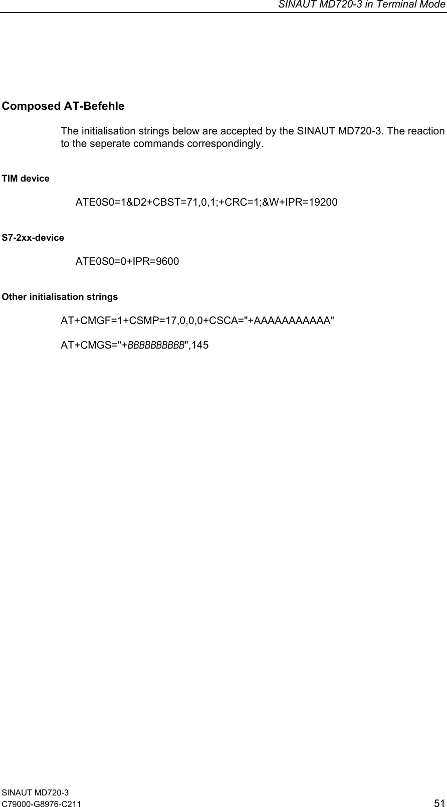
![SINAUT MD720-3 in Terminal Mode SINAUT MD720-3 C79000-G8976-C211 49 AT+CSMP Set SMS text mode parameters Test Command: AT+CSMP=? Response: +CSMP: (list of <fo>),(list of <vp>),(list of <pid>),(list of <dcs>) OK Read command Command: AT+CSMP? Response: +CSMP: <fo>,<vp>,<pid>,<dcs> OK Executive command Command: AT+CSMP=[<fo>[,<vp>[,<pid>[,<dcs>]]]] Response: OK Parameter: <fo> 17 <vp> Determines the period of time the SMS will be stored in the SMS ServiceCenter: 71 6 hours 167 24 hours 173 7 days 255 63 weeks <pid> 0 <dcs> 0 Notice: In the composite AT command AT+CMGF=1+CSMP=17,0,0,0+CSCA=" +AAAAAAAAAAA" the value 0 for <vp> will be accepted, but 0 will be replaced by the value 71.](https://usermanual.wiki/Siemens/MD720-3/User-Guide-626516-Page-49.png)
![SINAUT MD720-3 in Terminal Mode SINAUT MD720-3 50 C79000-G8976-C211 AT+CRC Set Cellular Result Codes for incoming call indication Test Command: AT+CRC=? Response: +CRC: (list of supported <mode>) OK Read command Command: AT+CRC? Response: +CRC:<mode> OK Executive command Command: AT+CRC=[<mode>] Response: OK Parameter: <mode>: 0: disable extended format <Default> 1: enable extended format Notice: When enabled, an incoming call is indicated with +CRING: <type> with, <type> : FAX or VOICE AT+IPR Set fixed local rate Test Command: AT+IPR=? Response: +IPR: (list of supported auto-detectable <rate>s), (list of supported fixed-only <rate>s) Read command Command: AT+IPR? Response: +IPR: <rate> OK Executive command Command: AT+IPR=<rate> Response: OK Parameter: <rate> bit rate per second 1200 2400 4800 9600 <Default> 14400 19200 28800 38400 57600 Notice: -](https://usermanual.wiki/Siemens/MD720-3/User-Guide-626516-Page-50.png)

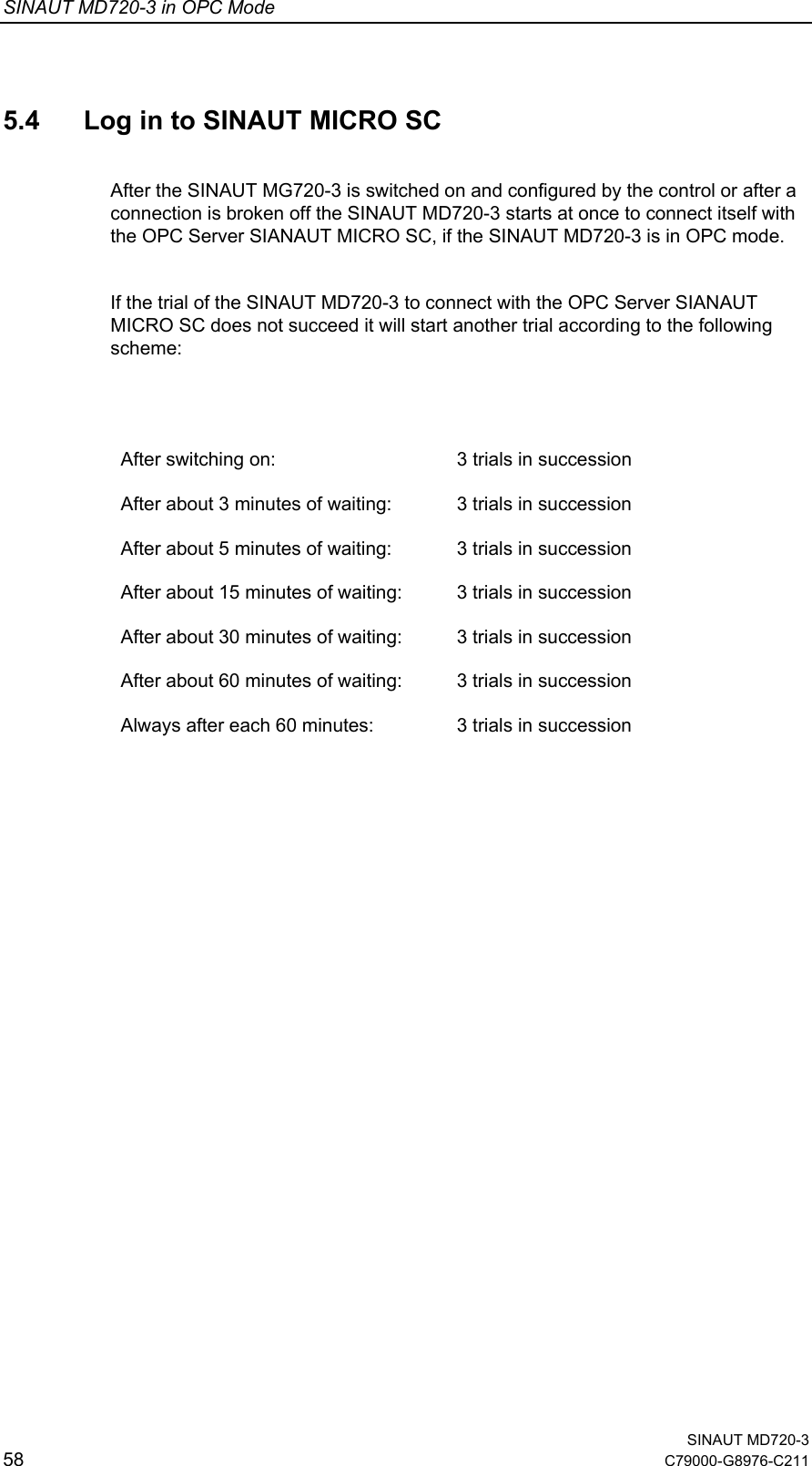
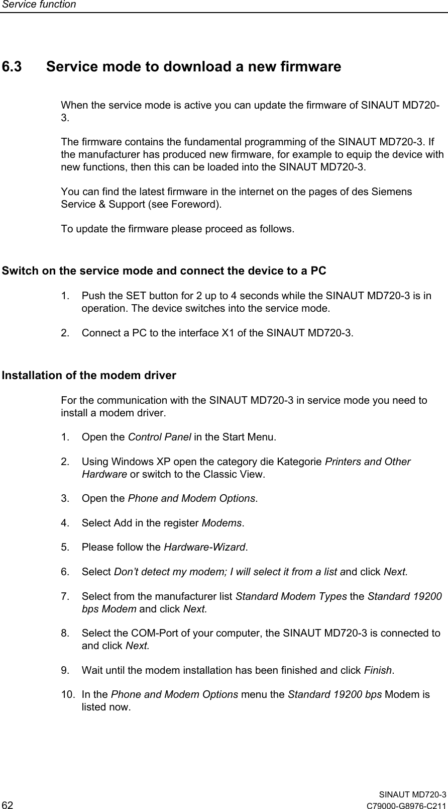
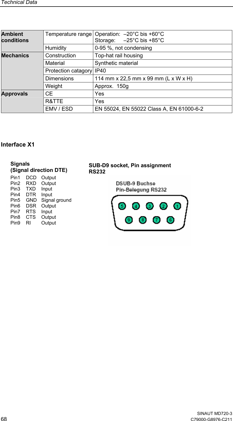
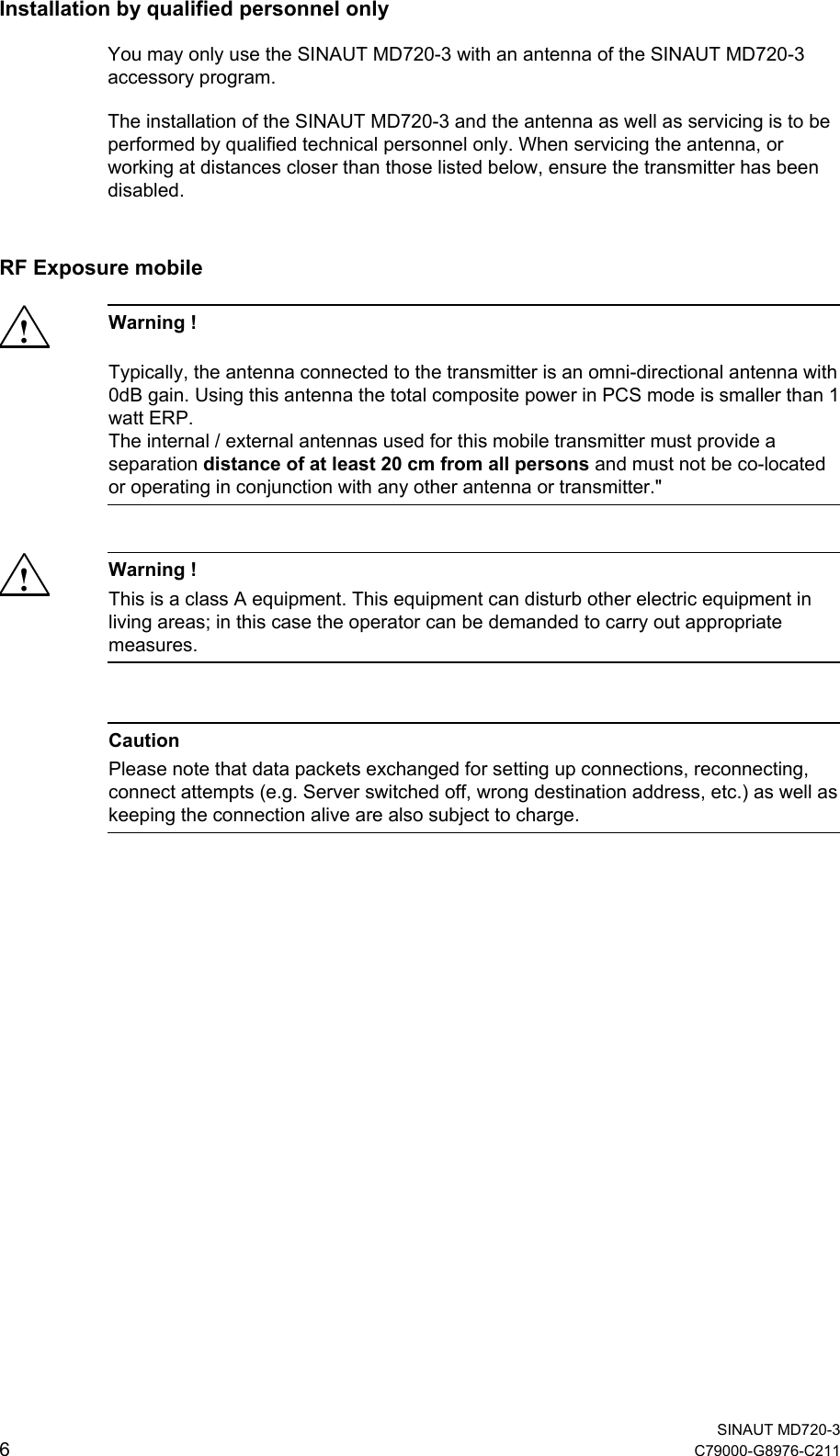
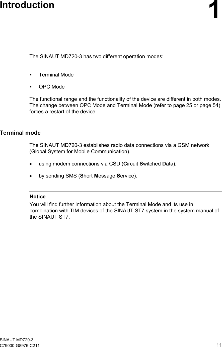
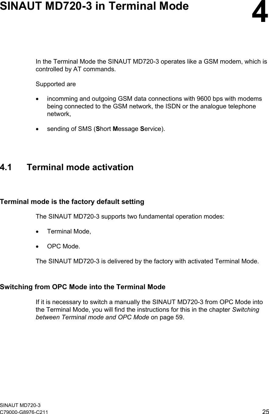
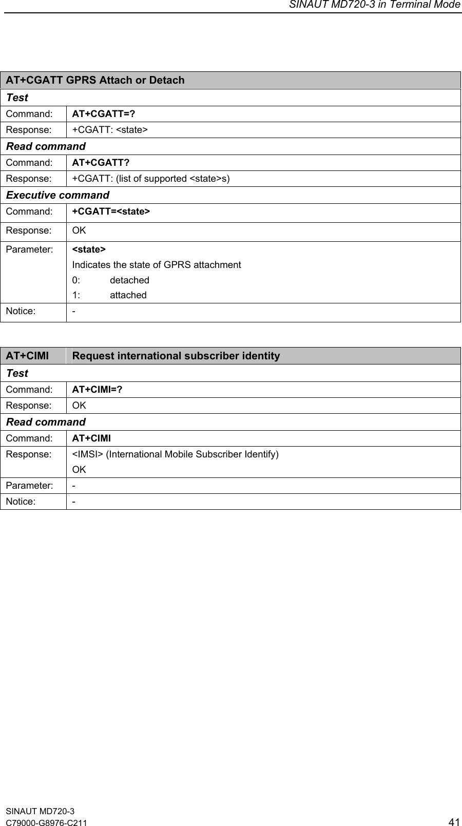
![Technical Data 7Function GPRS connections to SINAUT MICRO SC GSM data calls (CSD 9.600 bps) MTC SMS sending Standard RS-232 (V.24 / V.28), connector: SUB-D9 female Default speed 9600 bps Interface X1 Control AT commands GSM module GPRS / CSD / Quad band GPRS Up to 2 uplinks / up to 4 downlinks (max. 5 Slots) Transmit power GSM 850 MHz (max. 2W), GSM 900 MHz (max. 2W), DCS 1800 MHz (max. 1W), PCS 1900 MHz (max. 1W) Air interface Antenna connector SMA / 50 Ohm Supply voltage 12 - 30 VDC (24 VDC nominal) Power supply Supply current 100020040060080012001400[mA][ms]10 20 30 40 50 7060 80 90 100IBurstbei 12V100020040060080012001400[mA][ms]10 20 30 40 50 7060 80 90 100IBurst bei 24VIn 430mA at 12V (IBurst 1,3A), In 165mA beati 24V (IBurst 0,8A), 4,62ms Burst repetetion rate SINAUT MD720-3 C79000-G8976-C211 67](https://usermanual.wiki/Siemens/MD720-3/User-Guide-626516-Page-67.png)