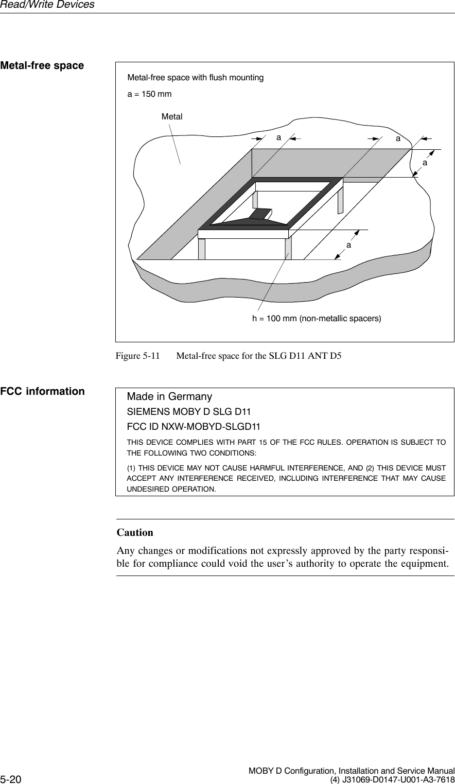
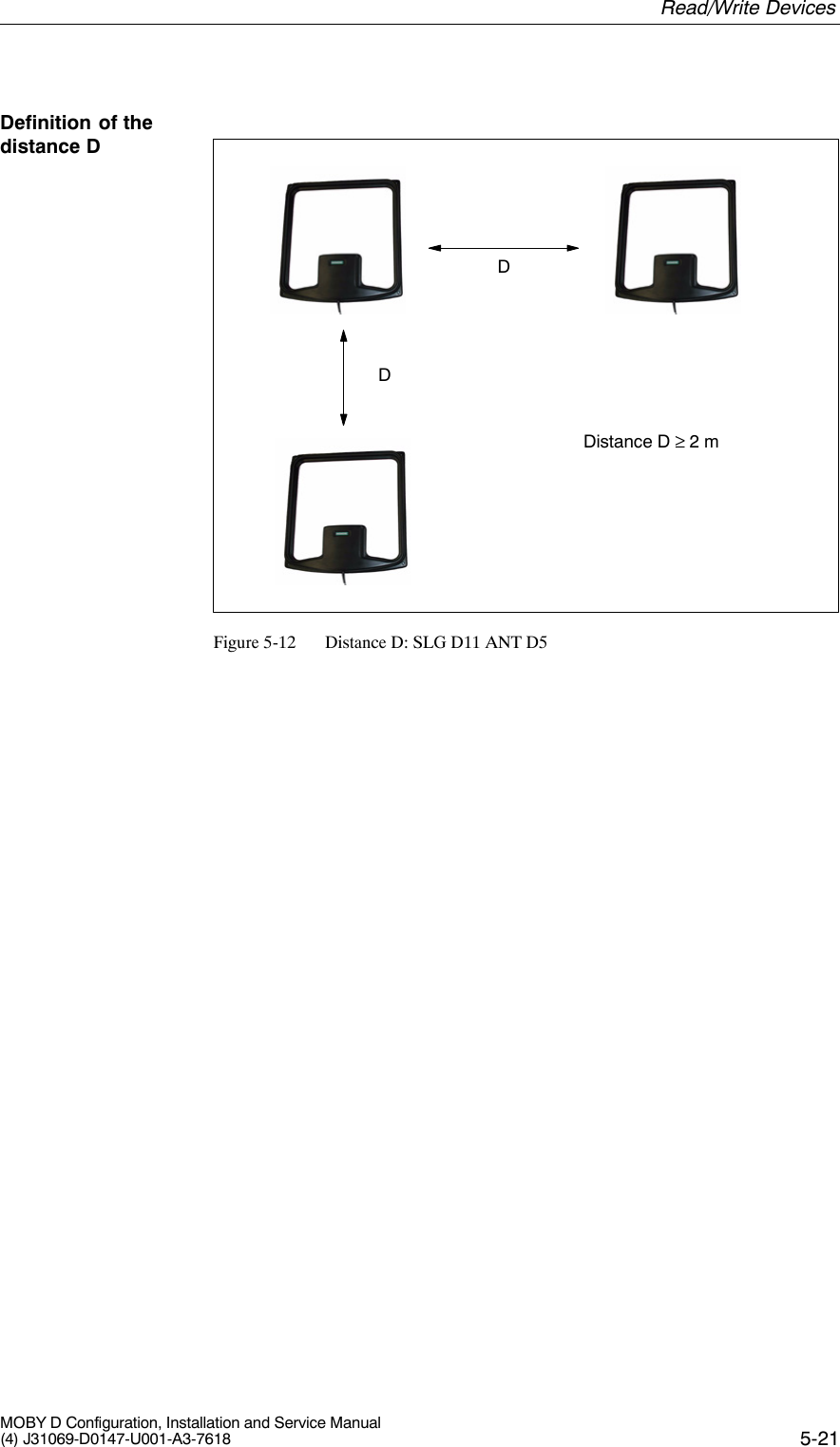
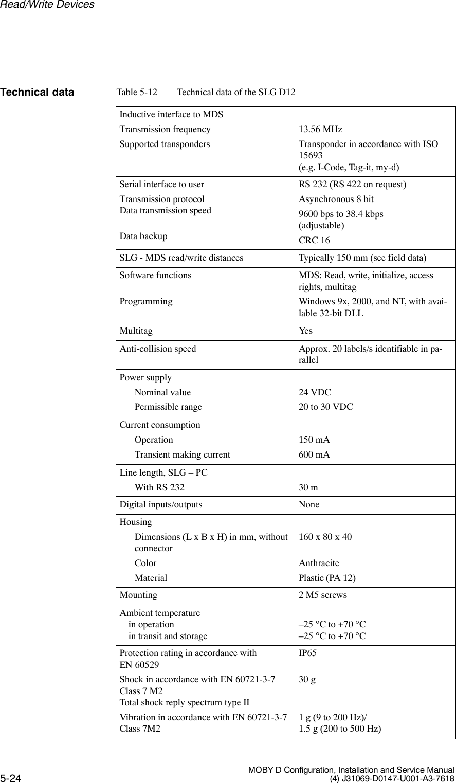
Siemens MOBYD-SLGD11 Tag Reader System User Manual Dokument
Siemens AG Tag Reader System Dokument
UserManual.wiki
>
Siemens
>
MOBYD SLGD11 User Manual
Users Manual
Navigation menu
Upload a User Manual
Namespaces
Wiki Guide
HTML
PDF
Info
Views
User Manual
Discussion / Help
Navigation
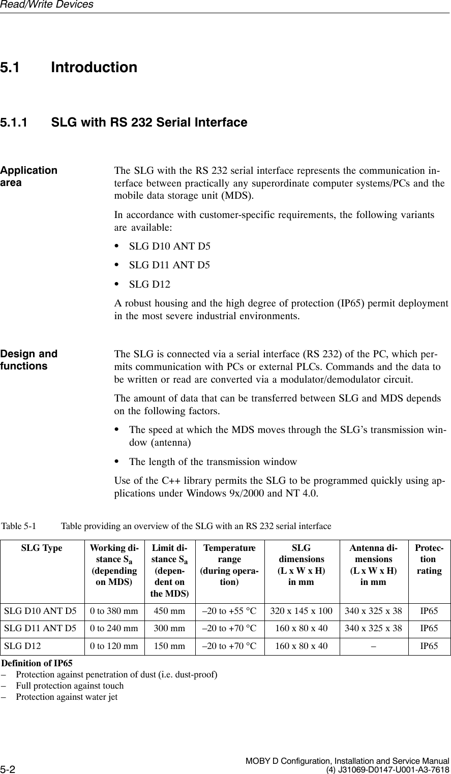
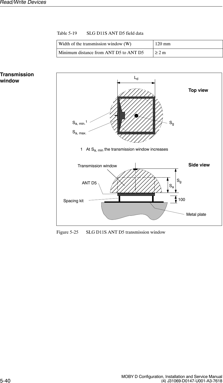
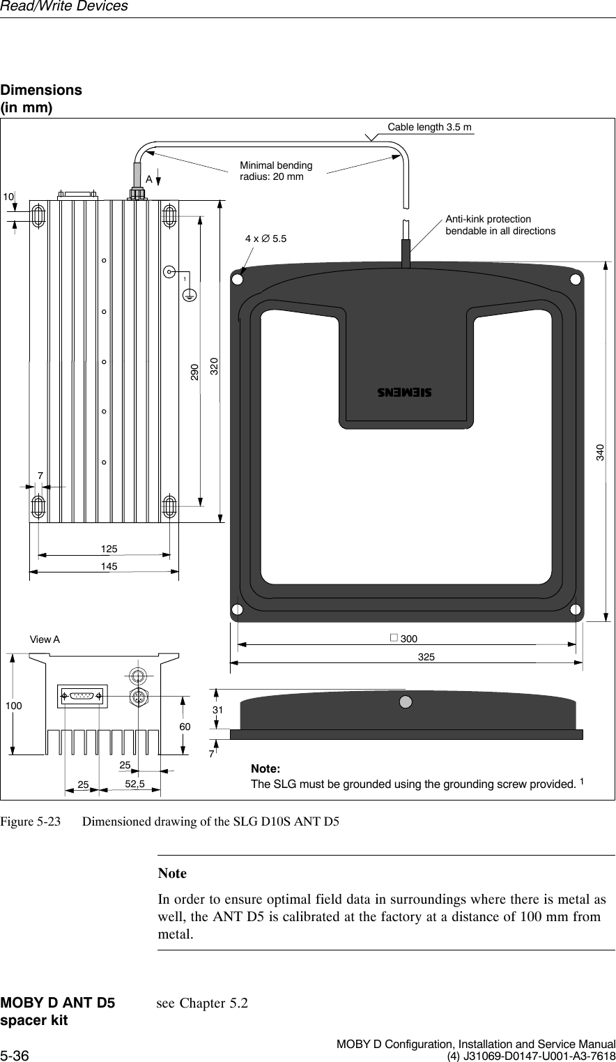
![5-8 MOBY D Configuration, Installation and Service Manual(4) J31069-D0147-U001-A3-7618Table 5-5 Technical data of the SLG D10 ANT D5Inductive interface to MDSTransmission frequencySupported transponders13.56 MHzTransponder in accordance with ISO15693 (e.g. I-Code, Tag-it, my-d)Serial interface to userTransmission protocolData transmission speedData backupRS 232 (RS 422 on request)Asynchronous 8 bit9600 bps to 115.2 kbps(adjustable)CRC 16Output power 4 WSLG - MDS read/write distances Typically 450 mm (see field data)1Software functionsProgrammingMDS: Read, write, initialize, accessrights, multitagWindows 9x, 2000, and NT, with available 32-bit DLLMultitag YesAnti-collision speed Approx. 20 labels/s identifiable inparallelPower supply 24 VDC ±5%Current consumptionOperationTransient making current0.9 A2.8 A/50 msLine length, SLG – PCWith RS 232With RS 422Antenna line length30 m300 m3.60 mDigital inputs/outputs NoneHousingDimensions (in mm)For antenna [L x W x H]For electronic components[L x W x H]Color AntennaSLG housingMaterial AntennaSLG housingConnectorAntenna (can be connected to the SLG)340 x 325 x 38320 x 145 x 100 (without connector)BlackAnthracitePlastic ASAAluminumTNC connectorMounting of SLGMounting of antenna4 M6 screws4 M5 screwsAmbient temperaturein operationin transit and storage–20 °C to +55 °C–25 °C to +70 °CTechnical dataRead/Write Devices](https://usermanual.wiki/Siemens/MOBYD-SLGD11/User-Guide-468044-Page-8.png)
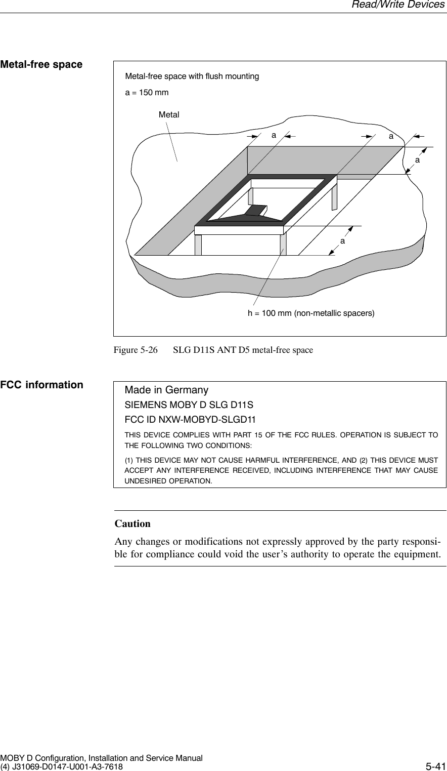
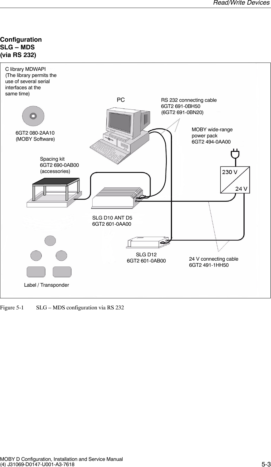
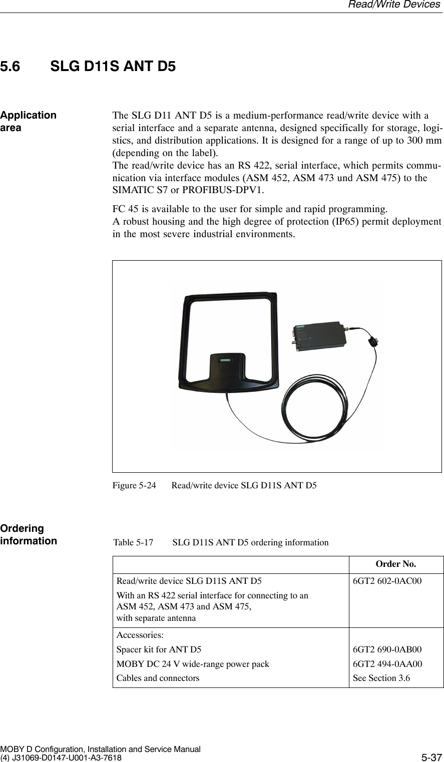
![5-17MOBY D Configuration, Installation and Service Manual(4) J31069-D0147-U001-A3-7618Table 5-9 Technical data of the SLG D11 ANT D5Inductive interface to MDSTransmission frequencySupported transponders13.56 MHzTransponder in accordance withISO 15693 (e.g. I-Code, Tag-it, my-d)Serial interface to userTransmission protocolData transmission speedData backupRS 232 (RS 422 on request)Asynchronous 8 bit9600 bps to 38.4 kbps(adjustable)CRC 16Output power 1 WSLG - MDS read/write distances Typically 300 mm (see field data)1Software functionsProgrammingMDS: Read, write, initialize, accessrights, multitagWindows 9x, 2000, and NT, with available 32-bit DLLMultitag YesAnti-collision speed Approx. 20 labels/s identifiable inparallelPower supplyNominal valuePermissible range24 VDC20 to 30 VDCCurrent consumptionOperationTransient making current150 mA600 mALine length, SLG – PCWith RS 232Antenna line length30 m3.60 mDigital inputs/outputs NoneHousingDimensions (in mm)For antenna [L x W x H]For electronic components[L x W x H]Color AntennaSLG housingMaterial AntennaSLG housingConnectorAntenna (can be connected to the SLG)340 x 325 x 38160 x 80 x 40 (without connector)BlackAnthracitePlastic ASAPlastic (PA 12)TNC connectorMounting of SLGMounting of antenna2 M5 screws4 M5 screwsTechnical dataRead/Write Devices](https://usermanual.wiki/Siemens/MOBYD-SLGD11/User-Guide-468044-Page-17.png)


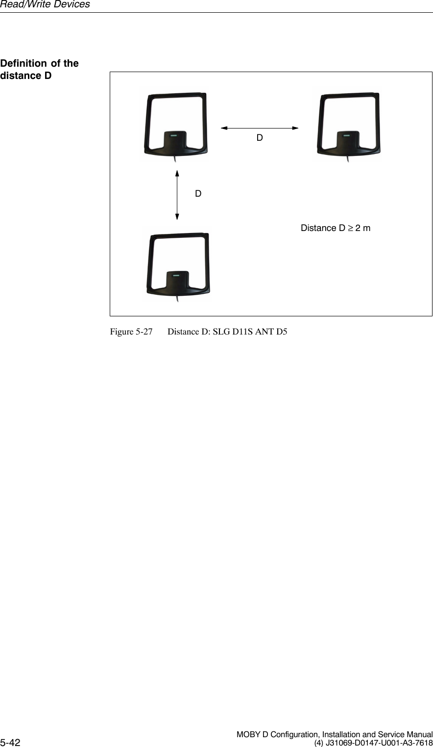
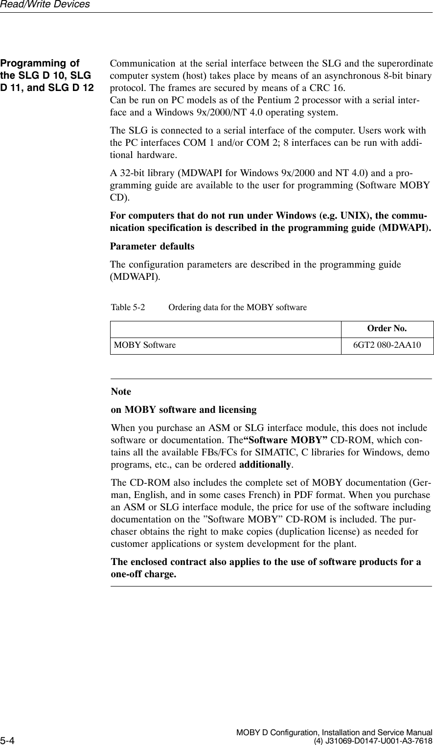
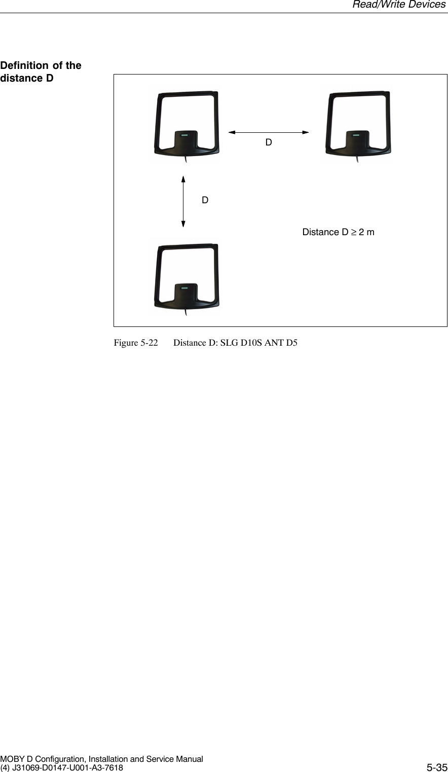
![5-31MOBY D Configuration, Installation and Service Manual(4) J31069-D0147-U001-A3-7618Table 5-15 Technical data of the SLG D10S ANT D5Current consumptionOperationTransient making current0.9 A2.8 A/50 msLine length (SLG – SIMATIC S7)With RS 422Antenna line length300 m3.60 mDigital inputs/outputs NoneHousingDimensions (in mm)For antenna [L x W x H]For electronic components [L x W x H]Color AntennaSLG housingMaterial AntennaSLG housingConnectorAntenna (can be connected to theSLG)340 x 325 x 38320 x 145 x 100 (without connector)BlackAnthracitePlastic ASAAluminumTNC connectorMounting of SLGMounting of antenna4 M6 screws4 M5 screwsAmbient temperaturein operationin transit and storage–20 °C to +55 °C–25 °C to +70 °CProtection rating in accordance withEN 60529SLG and antennaShock in accordance with EN 60721-3-7Class 7M2Total shock response spectrum type IIVibration in accordance with EN60721-3-7 Class 7M2IP6530 g1 g (9 to 200 Hz)/1.5 g (200 to 500 Hz)Weight, approx.SLGAntenna3500 g1000 gCertifications Radio EN 300 330CESafe for pacemakers1 To ensure optimal field data in a metallic environment, the ANT D5 is calibrated atthe factory at a distance of 100 mm from metal.Read/Write Devices](https://usermanual.wiki/Siemens/MOBYD-SLGD11/User-Guide-468044-Page-31.png)


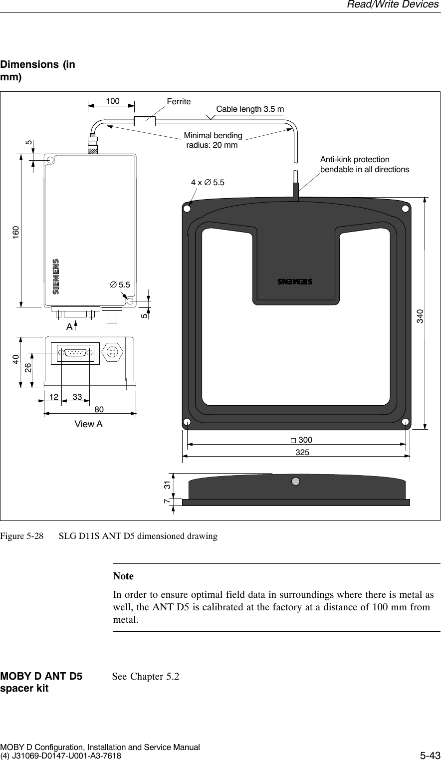
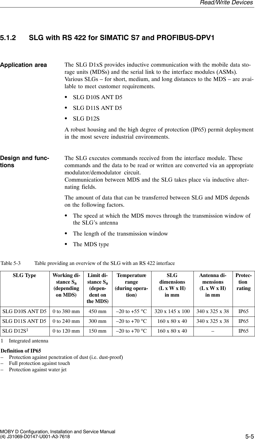
![5-39MOBY D Configuration, Installation and Service Manual(4) J31069-D0147-U001-A3-7618Table 5-18 SLG D11S ANT D5 technical dataHousingDimensions (in mm)For antenna [L x W x H]for the electronics [L x B x H]Color AntennaSLG housingMaterial AntennaSLG housingConnectorAntenna (can be connected to the SLG)340 x 325 x 38160 x 80 x 40 (without connector)BlackAnthracitePlastic ASAPlastic (PA 12)TNC connectorMounting of SLGMounting of antenna2 M5 screws4 M5 screwsAmbient temperaturein operationin transport and storage–25 °C to +70 °C–25 °C to +70 °CProtection rating in accordance with EN 60529SLG and antennaShock in accordance with EN 60721-3-7 Class 7M2Total shock reply spectrum type IIVibration in accordance with EN 60721-3-7Class 7M2IP6530 g1 g (9 to 200 Hz)/1.5 g (200 to 500 Hz)Weight, approx.SLGAntennaApprox. 600 gApprox. 1000 gCertifications Radio EN 300 330CESafe for pacemakers1 To ensure optimal field data in a metallic environment, the ANT D5 is calibrated atthe factory at a distance of 100 mm from metal.Table 5-19 SLG D11S ANT D5 field dataLimit distance (Sg)Max. 300 mm (dependent on transponder)Working distance (Sa)0 to 240 mm(dependent on transponder)Length of the transmission window (Ld)300 mmField data Read/Write Devices](https://usermanual.wiki/Siemens/MOBYD-SLGD11/User-Guide-468044-Page-39.png)