Siemens MOBYD-SLGD12 Tag Reader System User Manual Dokument
Siemens AG Tag Reader System Dokument
Siemens >
Users Manual
5-1
MOBY D Configuration, Installation and Service Manual
(4) J31069-D0147-U001-A3-7618
Read/Write Devices 5
5-2 MOBY D Configuration, Installation and Service Manual
(4) J31069-D0147-U001-A3-7618
5.1 Introduction
5.1.1 SLG with RS 232 Serial Interface
The SLG with the RS 232 serial interface represents the communication in-
terface between practically any superordinate computer systems/PCs and the
mobile data storage unit (MDS).
In accordance with customer-specific requirements, the following variants
are available:
SSLG D10 ANT D5
SSLG D11 ANT D5
SSLG D12
A robust housing and the high degree of protection (IP65) permit deployment
in the most severe industrial environments.
The SLG is connected via a serial interface (RS 232) of the PC, which per-
mits communication with PCs or external PLCs. Commands and the data to
be written or read are converted via a modulator/demodulator circuit.
The amount of data that can be transferred between SLG and MDS depends
on the following factors.
SThe speed at which the MDS moves through the SLG’s transmission win-
dow (antenna)
SThe length of the transmission window
Use of the C++ library permits the SLG to be programmed quickly using ap-
plications under Windows 9x/2000 and NT 4.0.
Table 5-1 Table providing an overview of the SLG with an RS 232 serial interface
SLG Type Working di-
stance Sa
(depending
on MDS)
Limit di-
stance Sa
(depen-
dent on
the MDS)
Temperature
range
(during opera-
tion)
SLG
dimensions
(L x W x H)
in mm
Antenna di-
mensions
(L x W x H)
in mm
Protec-
tion
rating
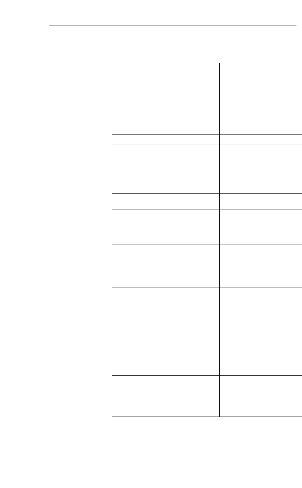
SLG D10 ANT D5 0 to 380 mm 450 mm –20 to +55 °C320 x 145 x 100 340 x 325 x 38 IP65
SLG D11 ANT D5 0 to 240 mm 300 mm –20 to +70 °C160 x 80 x 40 340 x 325 x 38 IP65
SLG D12 0 to 120 mm 150 mm –20 to +70 °C160 x 80 x 40 – IP65
Definition of IP65
– Protection against penetration of dust (i.e. dust-proof)
– Full protection against touch
– Protection against water jet
Application
area
Design and
functions
Read/Write Devices
5-3
MOBY D Configuration, Installation and Service Manual
(4) J31069-D0147-U001-A3-7618
SLG D10 ANT D5
6GT2 601-0AA00
Spacing kit
6GT2 690-0AB00
(accessories)
Label / Transponder
SLG D12
6GT2 601-0AB00 24 V connecting cable
6GT2 491-1HH50
MOBY wide-range
power pack
6GT2 494-0AA00
RS 232 connecting cable
6GT2 691-0BH50
(6GT2 691-0BN20)
PC
6GT2 080-2AA10
(MOBY Software)
C library MDWAPI
(The library permits the
use of several serial
interfaces at the
same time)
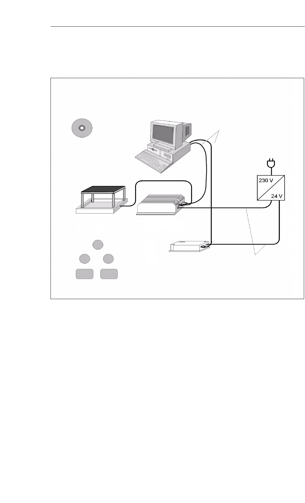
Figure 5-1 SLG – MDS configuration via RS 232
Configuration
SLG – MDS
(via RS 232)
Read/Write Devices
5-4 MOBY D Configuration, Installation and Service Manual
(4) J31069-D0147-U001-A3-7618
Communication at the serial interface between the SLG and the superordinate
computer system (host) takes place by means of an asynchronous 8-bit binary
protocol. The frames are secured by means of a CRC 16.
Can be run on PC models as of the Pentium 2 processor with a serial inter-
face and a Windows 9x/2000/NT 4.0 operating system.
The SLG is connected to a serial interface of the computer. Users work with
the PC interfaces COM 1 and/or COM 2; 8 interfaces can be run with addi-
tional hardware.
A 32-bit library (MDWAPI for Windows 9x/2000 and NT 4.0) and a pro-
gramming guide are available to the user for programming (Software MOBY
CD).
For computers that do not run under Windows (e.g. UNIX), the commu-
nication specification is described in the programming guide (MDWAPI).
Parameter defaults
The configuration parameters are described in the programming guide
(MDWAPI).
Table 5-2 Ordering data for the MOBY software
Order No.
MOBY Software 6GT2 080-2AA10
Note
on MOBY software and licensing
When you purchase an ASM or SLG interface module, this does not include
software or documentation. The“Software MOBY” CD-ROM, which con-
tains all the available FBs/FCs for SIMATIC, C libraries for Windows, demo
programs, etc., can be ordered additionally.
The CD-ROM also includes the complete set of MOBY documentation (Ger-
man, English, and in some cases French) in PDF format. When you purchase
an ASM or SLG interface module, the price for use of the software including
documentation on the ”Software MOBY” CD-ROM is included. The pur-
chaser obtains the right to make copies (duplication license) as needed for
customer applications or system development for the plant.
The enclosed contract also applies to the use of software products for a
one-off charge.
Programming of
the SLG D 10, SLG
D 11, and SLG D 12
Read/Write Devices
5-5
MOBY D Configuration, Installation and Service Manual
(4) J31069-D0147-U001-A3-7618
5.1.2 SLG with RS 422 for SIMATIC S7 and PROFIBUS-DPV1
The SLG D1xS provides inductive communication with the mobile data sto-
rage units (MDSs) and the serial link to the interface modules (ASMs).
Various SLGs – for short, medium, and long distances to the MDS – are avai-
lable to meet customer requirements.
SSLG D10S ANT D5
SSLG D11S ANT D5
SSLG D12S
A robust housing and the high degree of protection (IP65) permit deployment
in the most severe industrial environments.
The SLG executes commands received from the interface module. These
commands and the data to be read or written are converted via an appropriate
modulator/demodulator circuit.
Communication between MDS and the SLG takes place via inductive alter-
nating fields.
The amount of data that can be transferred between SLG and MDS depends
on the following factors.
SThe speed at which the MDS moves through the transmission window of
the SLG’s antenna
SThe length of the transmission window
SThe MDS type
Table 5-3 Table providing an overview of the SLG with an RS 422 interface
SLG Type Working di-
stance Sa
(depending
on MDS)
Limit di-
stance Sa
(depen-
dent on
the MDS)
Temperature
range
(during opera-
tion)
SLG
dimensions
(L x W x H)
in mm
Antenna di-
mensions
(L x W x H)
in mm
Protec-
tion
rating
SLG D10S ANT D5 0 to 380 mm 450 mm –20 to +55 °C320 x 145 x 100 340 x 325 x 38 IP65
SLG D11S ANT D5 0 to 240 mm 300 mm –20 to +70 °C160 x 80 x 40 340 x 325 x 38 IP65
SLG D12S10 to 120 mm 150 mm –20 to +70 °C160 x 80 x 40 – IP65
1 Integrated antenna
Definition of IP65
– Protection against penetration of dust (i.e. dust-proof)
– Full protection against touch
– Protection against water jet
Application area
Design and func-
tions
Read/Write Devices

5-6 MOBY D Configuration, Installation and Service Manual
(4) J31069-D0147-U001-A3-7618
5.1.3 Troubleshooting
1. Check the supply voltage directly on the SLG connector using a measur-
ing instrument.
2. Check the cabling to the PC
– Do the SLG and PC have the same physical interface?
– Is the polarity of the connecting cable correct (RS 232)?
(RxD of the SLG must be connected to TxD of the PC and vice versa)
– Is the cable shield applied correctly?
Error messages are described in the programming guide (MDWAPI).
If the SLG range is too low, check:
– The power supply unit/switched-mode power supply unit (see Sec-
tion 3.4 on electrical interference)
– Whether there are monitors or other sources of interference in the vi-
cinity (see Section 3.4)
– Whether there is metal in the immediate vicinity (see Section 3.3)
– To attain optimal read/write distances for the ANT D 5, a metal plate
is required at a distance of 100 mm (see Table 3-8 and 3-9).
What should you
do if nothing
works?
Error messages
SLG range too low
Read/Write Devices

5-7
MOBY D Configuration, Installation and Service Manual
(4) J31069-D0147-U001-A3-7618
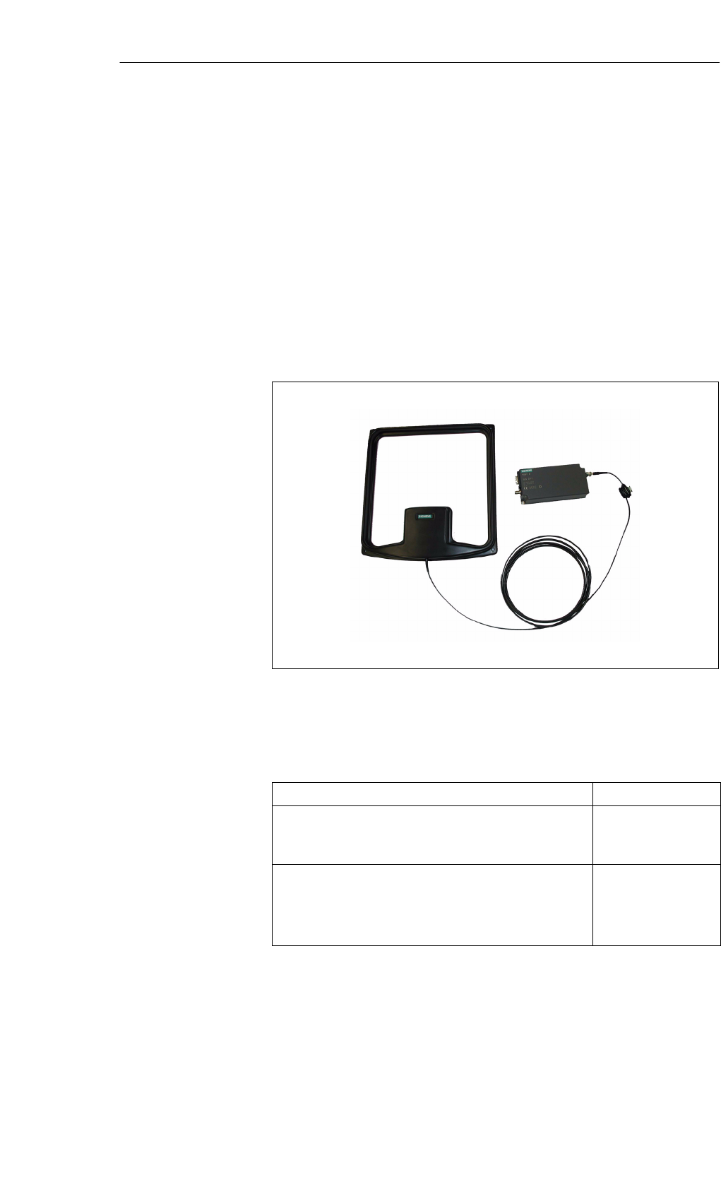
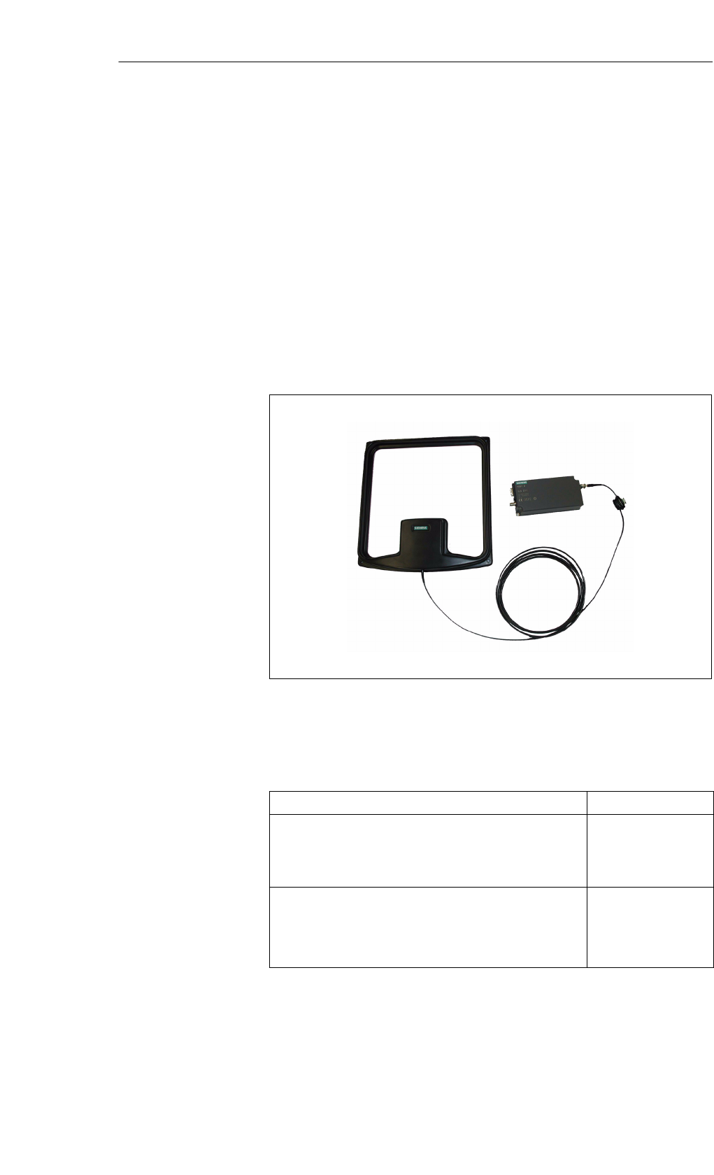
5.2 SLG D10 ANT D5
The SLG D10 ANT D5 is a high-performance read/write device with a serial
interface and a separate antenna, designed specifically for storage, logistics,
and distribution applications. It is designed for a range of up to 600 mm (de-
pending on the label). The read/write device has an RS 232 serial interface
(RS 422 interface on request), which permits communication with PCs or
external PLCs.
For simple and rapid programming there is a C library available to the user
that can be used under Windows 9x, 2000, and NT. The SLG D10 ANT D5 is
multitag capable.
Figure 5-2 Read/write device SLG D10 ANT D5
Table 5-4 Ordering data for the SLG D10 ANT D5
Order No.
Read/write device SLG D10 ANT D5
with an RS 232 serial interface for standard PCs,
with a separate antenna
6GT2 601-0AA00
Accessories:
Spacer kit for ANT D5
MOBY wide-range power pack
Cables and connectors
6GT2 690-0AB00
6GT2 494-0AA00
See Section 3.6
Application
area
Ordering data
Read/Write Devices
5-8 MOBY D Configuration, Installation and Service Manual
(4) J31069-D0147-U001-A3-7618
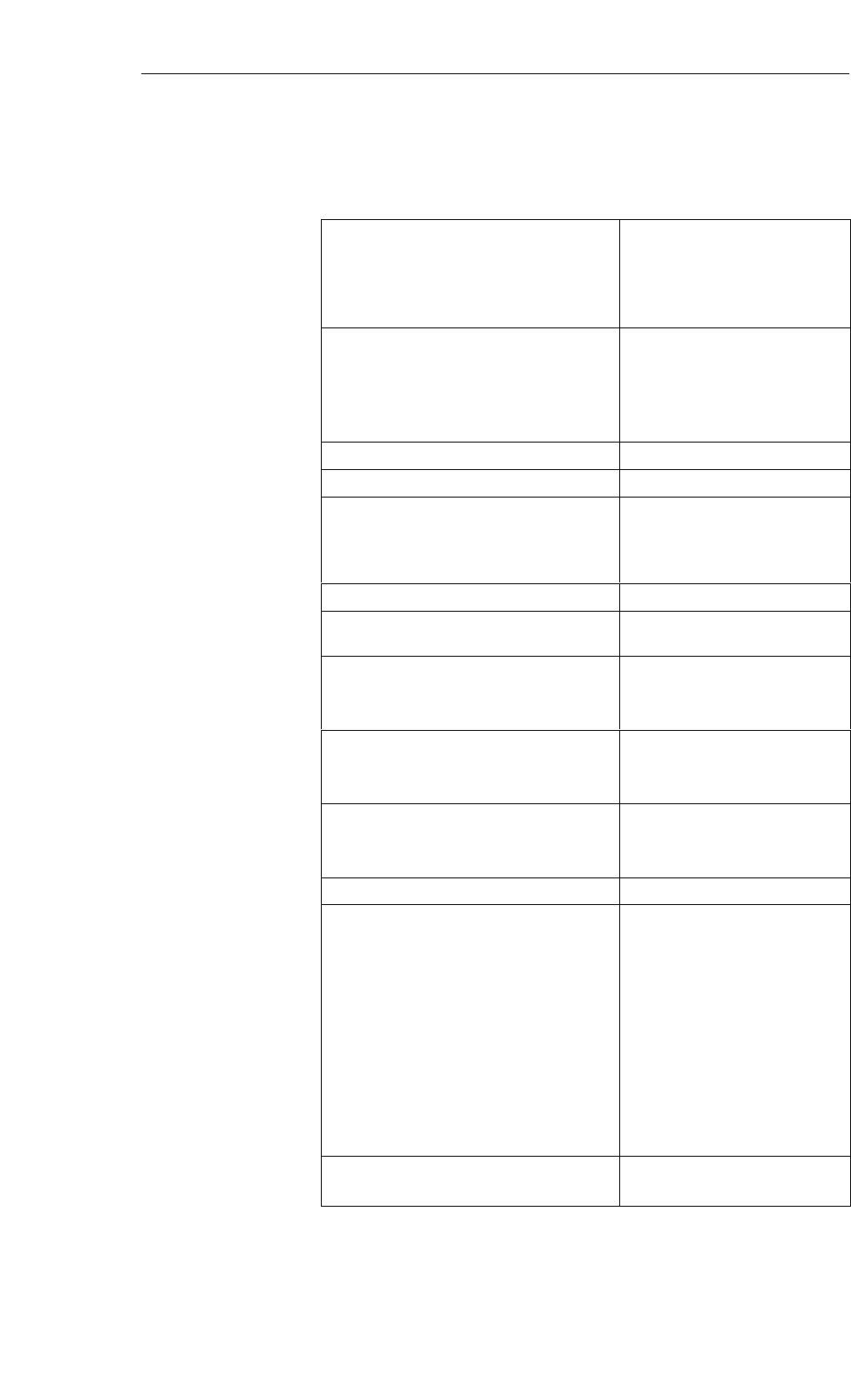
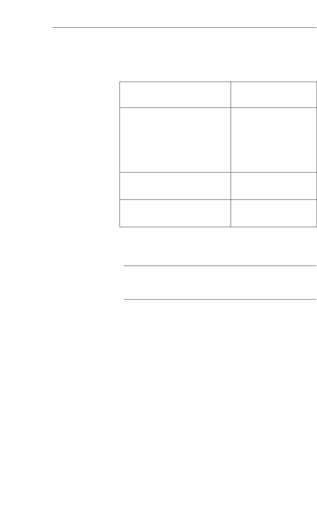
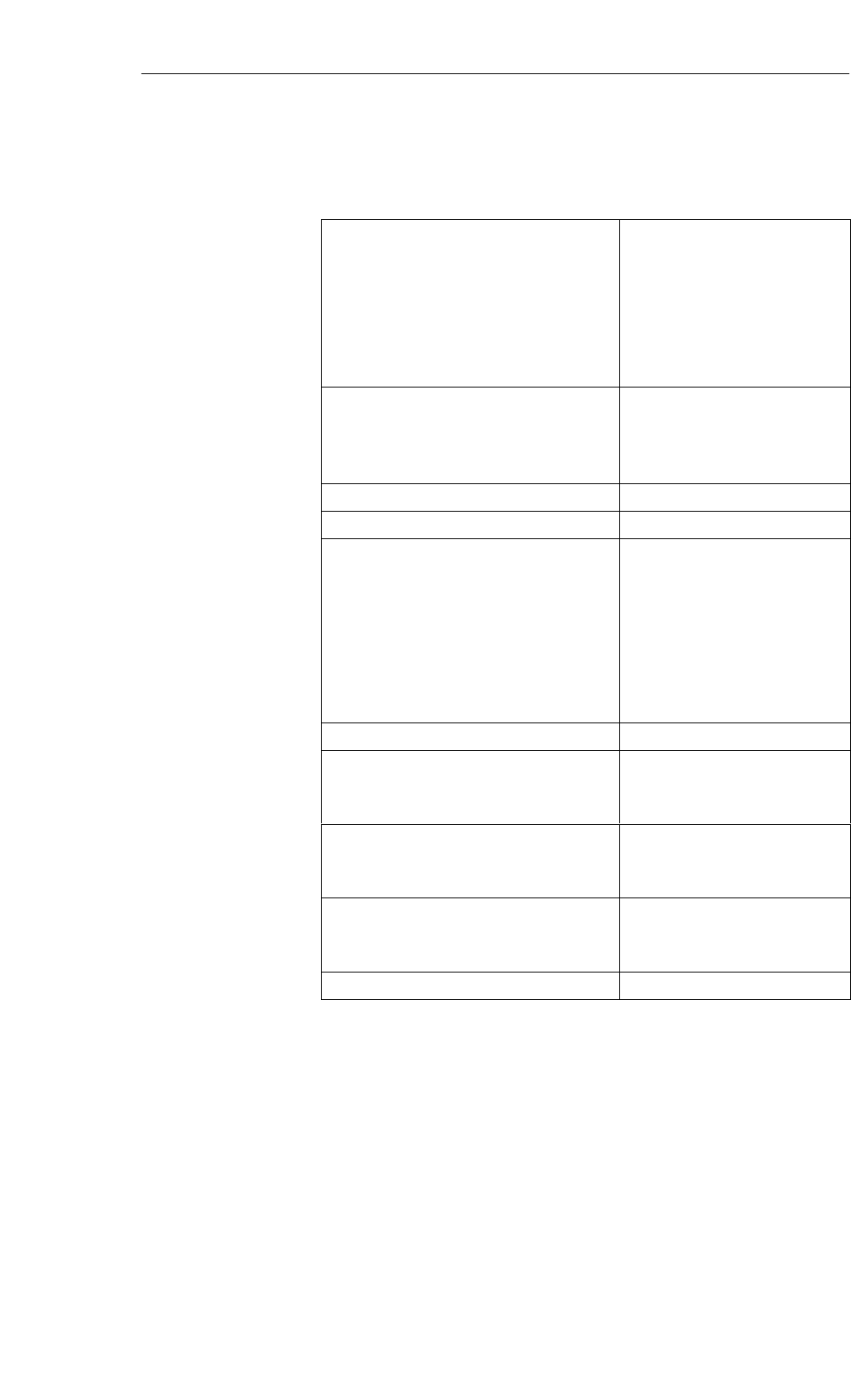
Table 5-5 Technical data of the SLG D10 ANT D5
Inductive interface to MDS
Transmission frequency
Supported transponders
13.56 MHz
Transponder in accordance with ISO
15693 (e.g. I-Code, Tag-it, my-d)
Serial interface to user
Transmission protocol
Data transmission speed
Data backup
RS 232 (RS 422 on request)
Asynchronous 8 bit
9600 bps to 115.2 kbps
(adjustable)
CRC 16
Output power 4 W
SLG - MDS read/write distances Typically 450 mm (see field data)1
Software functions
Programming
MDS: Read, write, initialize, access
rights, multitag
Windows 9x, 2000, and NT,
with available 32-bit DLL
Multitag Yes
Anti-collision speed Approx. 20 labels/s identifiable in
parallel
Power supply 24 VDC ±5%
Current consumption
Operation
Transient making current
0.9 A
2.8 A/50 ms
Line length, SLG – PC
With RS 232
With RS 422
Antenna line length
30 m
300 m
3.60 m
Digital inputs/outputs None
Housing
Dimensions (in mm)
For antenna [L x W x H]
For electronic components
[L x W x H]
Color Antenna
SLG housing
Material Antenna
SLG housing
Connector
Antenna (can be connected to the SLG)
340 x 325 x 38
320 x 145 x 100 (without connector)
Black
Anthracite
Plastic ASA
Aluminum
TNC connector
Mounting of SLG
Mounting of antenna
4 M6 screws
4 M5 screws
Ambient temperature
in operation
in transit and storage
–20 °C to +55 °C
–25 °C to +70 °C
Technical data
Read/Write Devices

5-9
MOBY D Configuration, Installation and Service Manual
(4) J31069-D0147-U001-A3-7618
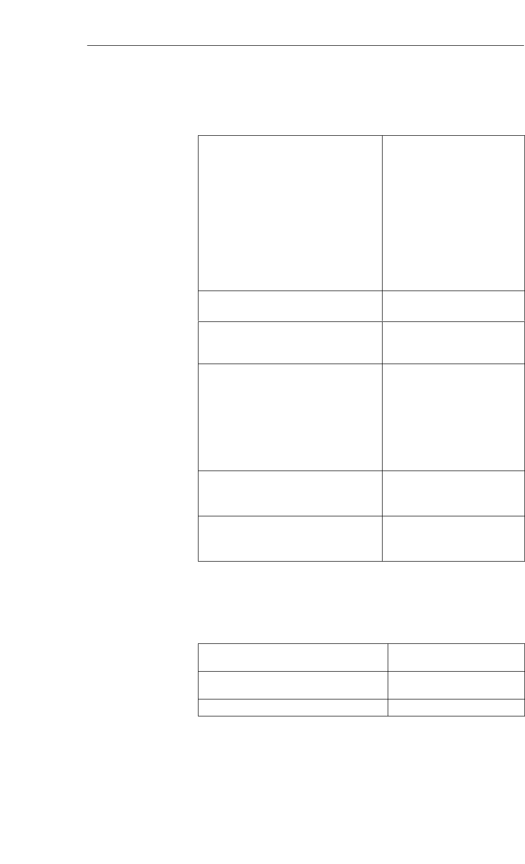
Table 5-5 Technical data of the SLG D10 ANT D5
Protection rating in accordance with EN 60529
SLG and antenna
Shock in accordance with
EN 60721-3-7 Class 7M2
Total shock response spectrum type II
Vibration in accordance with EN 60721-3-7
Class 7M2
IP65
30 g
1 g (9 to 200 Hz)/
1.5 g (200 to 500 Hz)
Weight, approx.
SLG
Antenna
3500 g
1000 g
Certifications Radio EN 300 330
CE
Safe for pacemakers
1 To ensure optimal field data in a metallic environment, the ANT D5 is calibrated at the
factory at a distance of 100 mm from metal.
Caution
The antenna cable is prepared in advance. If the cable is changed, the war-
ranty and CE marking become invalid.
Read/Write Devices

5-10 MOBY D Configuration, Installation and Service Manual
(4) J31069-D0147-U001-A3-7618
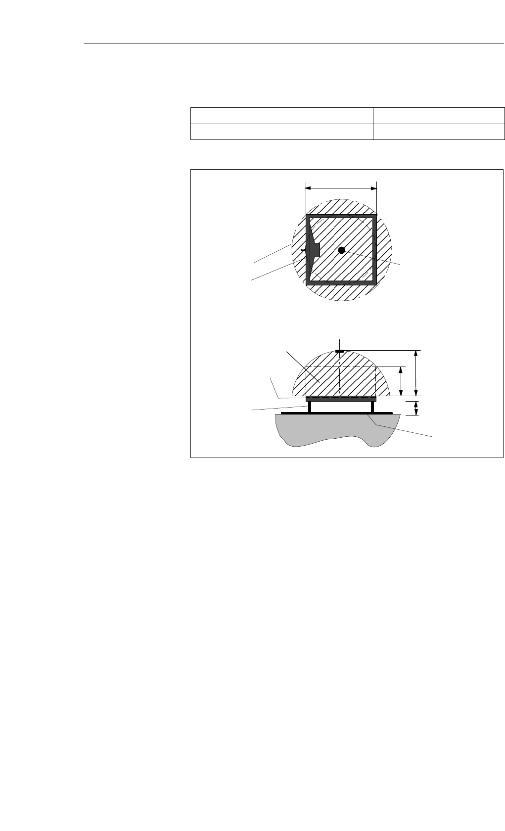
Table 5-6 Field data of the SLG D10 ANT D5
Limit distance (Sg)Max. 450 mm
(dependent on transponder)
Working distance (Sa)0 to 380 mm
(dependent on transponder)
Length of the transmission window (Ld)320 mm
Width of the transmission window (W) 128 mm
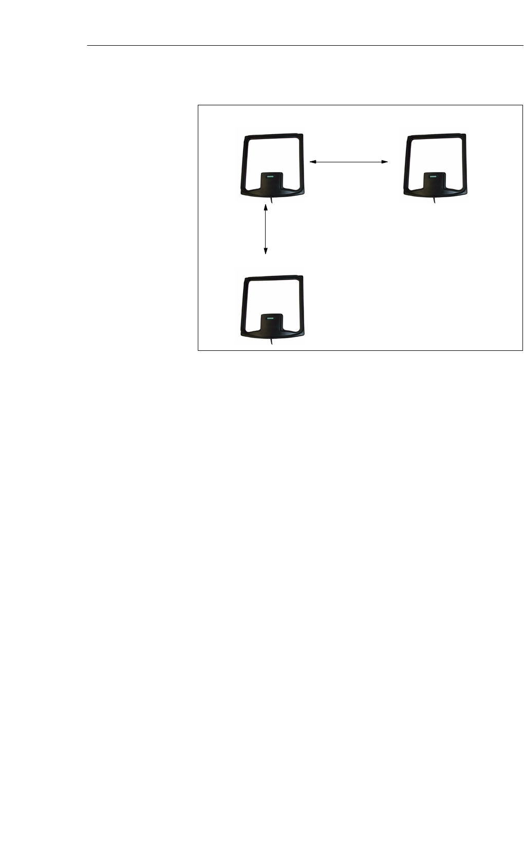
Minimum distance from ANT D5 to ANT D5 ≥ 2 m
Sg
Side view
Transmission window
Top view
Sa
Ld
100
Metal plate
ANT D5
Sa, min.1
Sa, max.
Sg
1 At Sa, min the transmission window increases
Spacing kit
Figure 5-3 Transmission window with the SLG D10 ANT D5
Field data
Transmission
window
Read/Write Devices

5-11
MOBY D Configuration, Installation and Service Manual
(4) J31069-D0147-U001-A3-7618
Metal-free space with flush mounting
a = 150 mm
a
Metal
a
a
a
h = 100 mm (non-metallic spacers)
Figure 5-4 Metal-free space for the SLG D10 ANT D5
Made in Germany
SIEMENS MOBY D SLG D10
FCC ID NXW-MOBYD-SLGD10
THIS DEVICE COMPLIES WITH PART 15 OF THE FCC RULES. OPERATION IS SUBJECT TO
THE FOLLOWING TWO CONDITIONS:
(1) THIS DEVICE MAY NOT CAUSE HARMFUL INTERFERENCE, AND (2) THIS DEVICE MUST
ACCEPT ANY INTERFERENCE RECEIVED, INCLUDING INTERFERENCE THAT MAY CAUSE
UNDESIRED OPERATION.
Caution
Any changes or modifications not expressly approved by the party responsi-
ble for compliance could void the user’s authority to operate the equipment.
Metal-free space
FCC information
Read/Write Devices
5-12 MOBY D Configuration, Installation and Service Manual
(4) J31069-D0147-U001-A3-7618
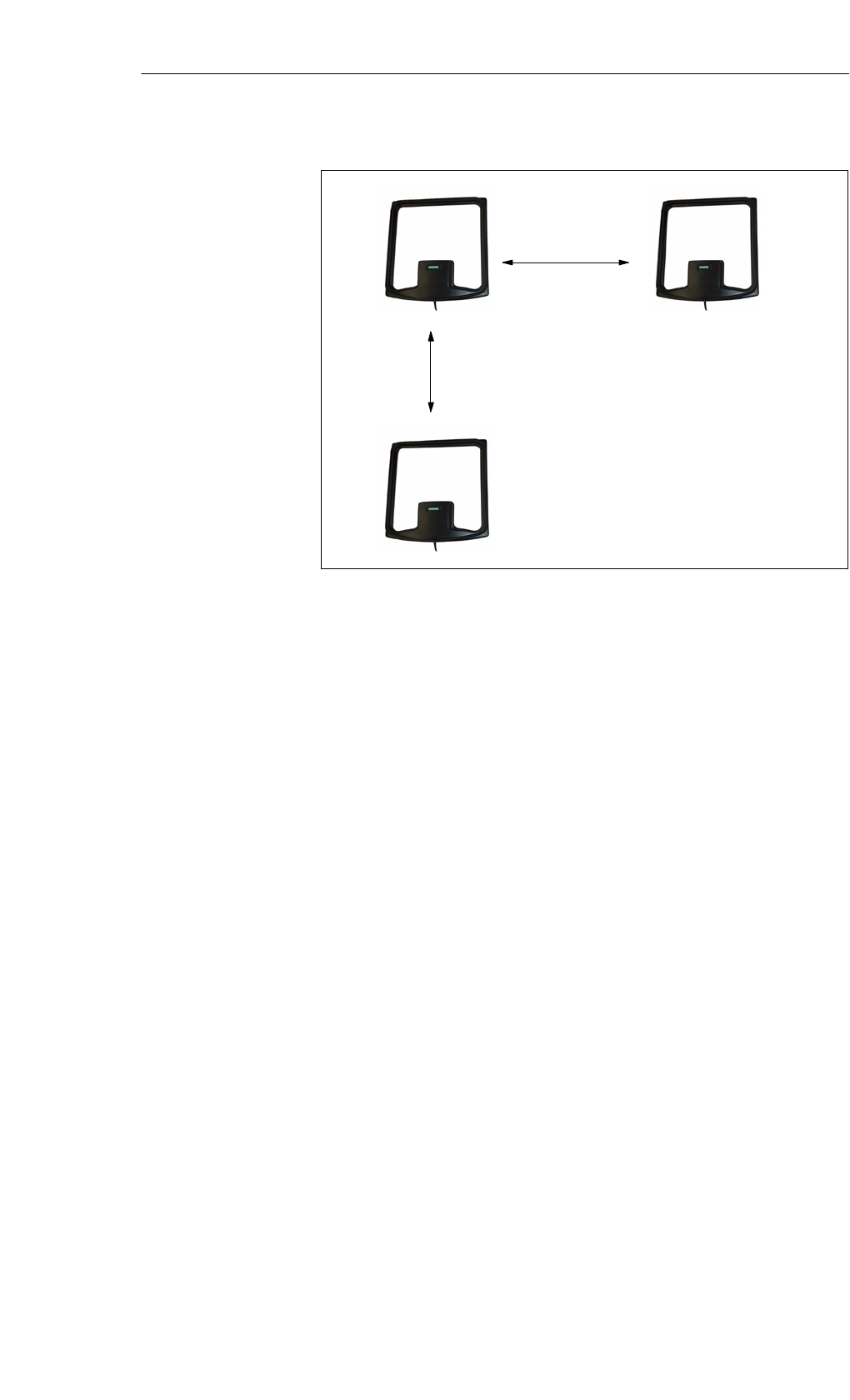
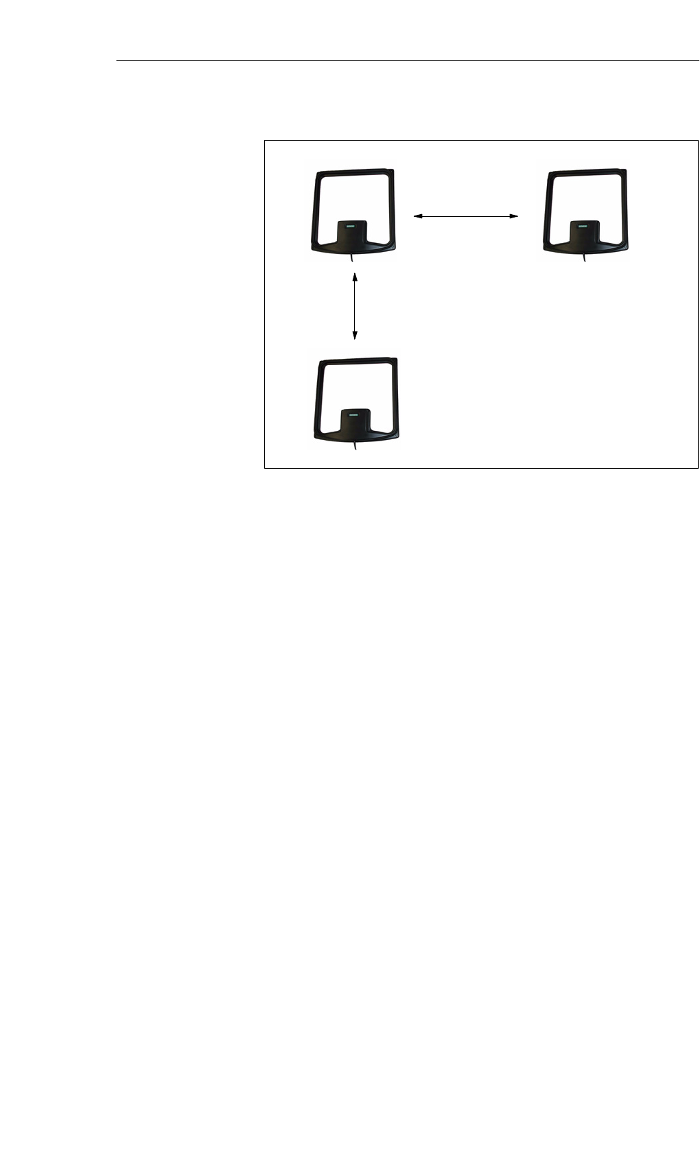
Distance D ≥ 2 m
D
D
Figure 5-5 Distance D: SLG D10 ANT D5
Definition of the
distance D
Read/Write Devices
5-13
MOBY D Configuration, Installation and Service Manual
(4) J31069-D0147-U001-A3-7618
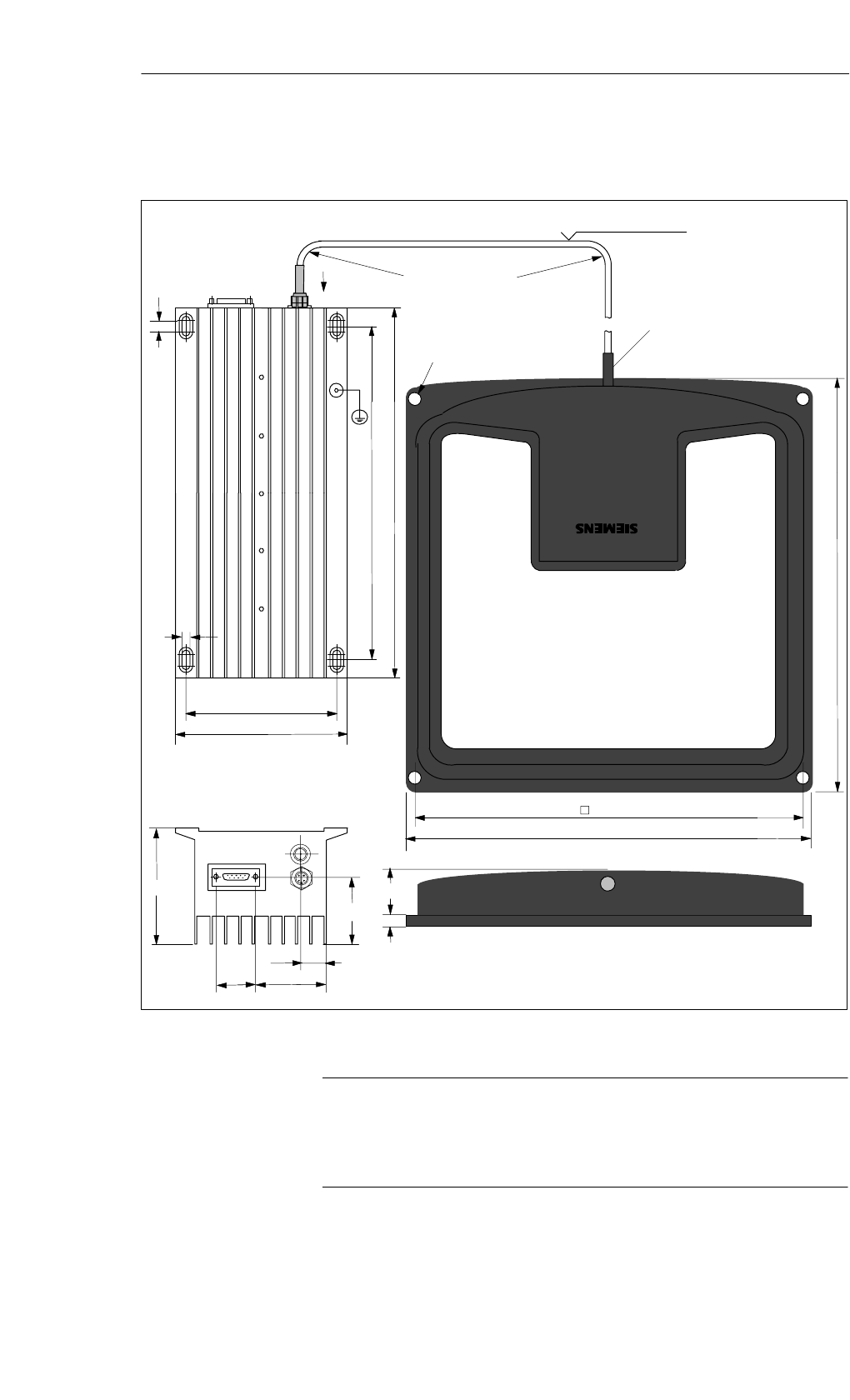
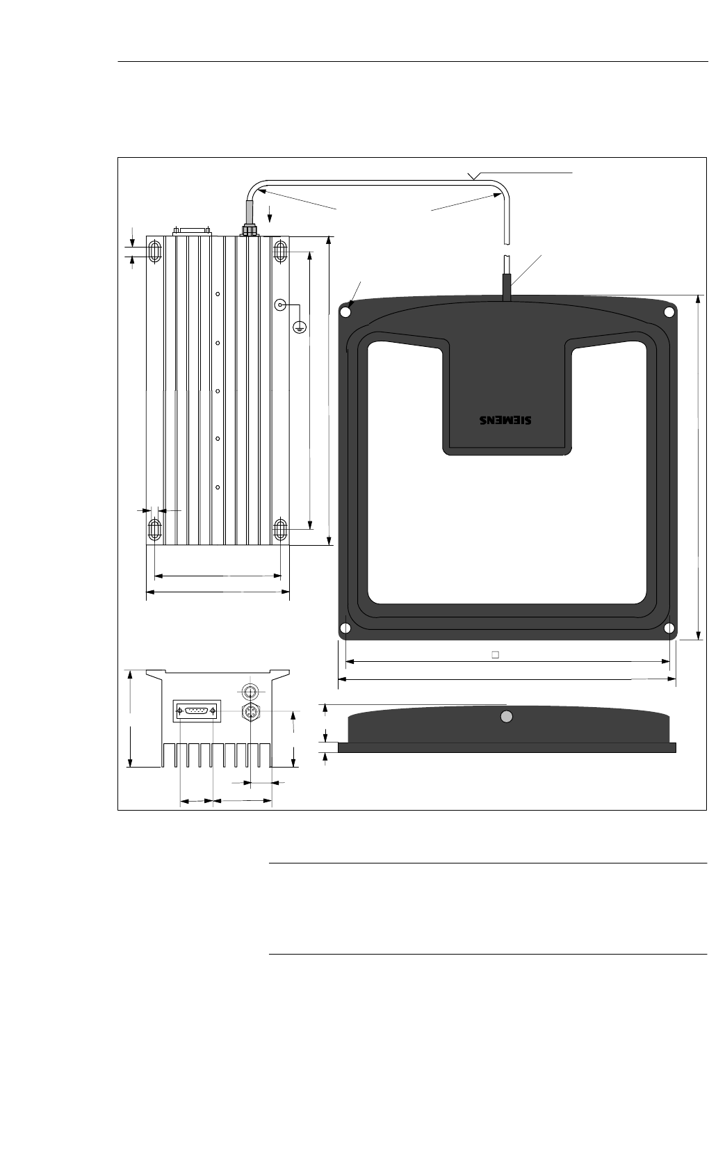
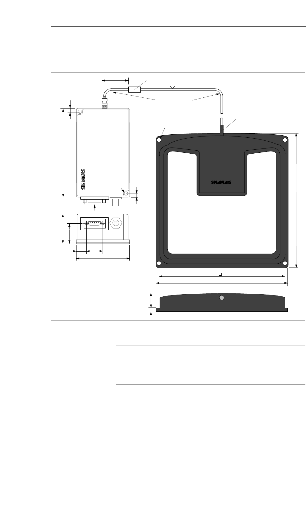
Anti-kink protection
bendable in all directions
Minimal bending
radius: 20 mm
Cable length 3.5 m
325
145
320
10
7
125
A
View A
100
52,5
Note:
The SLG must be grounded using the grounding screw provided. 1
1
290
25
300
31
25
340
60
7
4 x ∅ 5.5
Figure 5-6 Dimensioned drawing of the SLG D10 ANT D5
Note
In order to ensure optimal field data in surroundings where there is metal as
well, the ANT D5 is calibrated at the factory at a distance of 100 mm from
metal.
Dimensions
(in mm)
Read/Write Devices
5-14 MOBY D Configuration, Installation and Service Manual
(4) J31069-D0147-U001-A3-7618
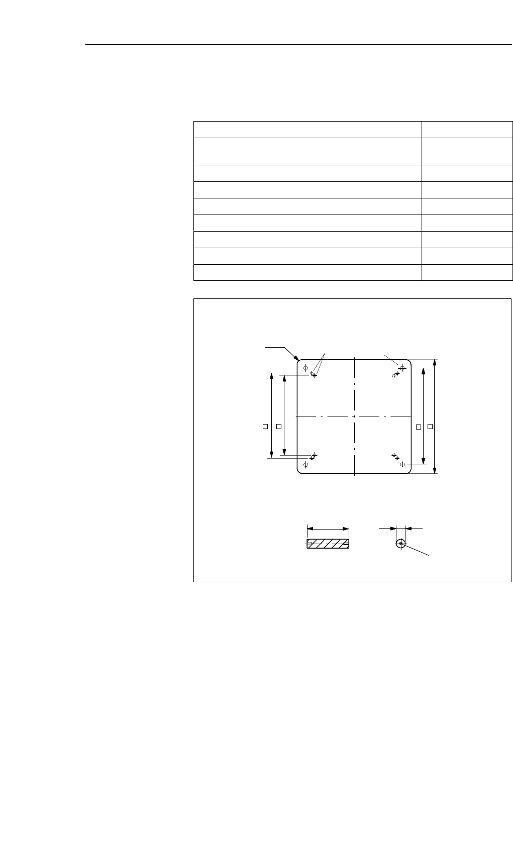
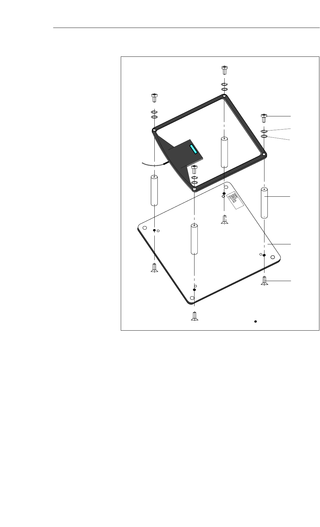
Table 5-7 Ordering data for the spacing kit MOBY D ANT D5
Order No.
Spacing kit for the ANT D5 made of aluminum with plastic
spacers including fixing screws
6GT2 690-0AB00
Individual parts Quantity
Aluminum plate 380 x 380 x 2 1
Plastic bolts 100 x 20 4
Countersunk head screws M5 x 12 4
Cylinder head screws M5 x 15 4
Washer for M5 4
Spring lock washer for M5 4
380
340
300
280
∅6∅9
∅20
100
M5 x 20
Aluminum plate:
Plastic bolts:
T = 2
10 R
Figure 5-7 Dimensioned drawing for the spacing kit for the MOBY D ANT D5
Spacing kit for the
MOBY D ANT D5
Read/Write Devices
5-15
MOBY D Configuration, Installation and Service Manual
(4) J31069-D0147-U001-A3-7618
4
5
6
2
1
3
Holes for ANT D5
Figure 5-8 Mounting diagram for spacer kit
Read/Write Devices
5-16 MOBY D Configuration, Installation and Service Manual
(4) J31069-D0147-U001-A3-7618
5.3 SLG D11 ANT D5
The SLG D11 ANT D5 is a medium-performance read/write device with a
serial interface and a separate antenna, designed specifically for storage, logi-
stics, and distribution applications. It is designed for a range of up to 300 mm
(depending on the label).
The read/write device has an RS 232 serial interface (RS 422 interface on
request), which permits communication with PCs or external PLCs.
For simple and rapid programming there is a C library available to the user
that can be used under Windows 9x, 2000, and NT. The SLG D11 ANT D5 is
multitag capable.
Figure 5-9 Read/write device SLG D11 ANT D5
Table 5-8 Ordering data for the SLG D11 ANT D5
Order No.
Read/write device SLG D11 ANT D5
with an RS 232 serial interface for standard PCs,
with a separate antenna
6GT2 601-0AC00
Accessories:
ANT D5 spacer kit
MOBY wide-range power pack
Cable and connector
6GT2 690-0AB00
6GT2 494-0AA00
See Section 3.6
Application
area
Ordering data
Read/Write Devices
5-17
MOBY D Configuration, Installation and Service Manual
(4) J31069-D0147-U001-A3-7618
Table 5-9 Technical data of the SLG D11 ANT D5
Inductive interface to MDS
Transmission frequency
Supported transponders
13.56 MHz
Transponder in accordance with
ISO 15693
(e.g. I-Code, Tag-it, my-d)
Serial interface to user
Transmission protocol
Data transmission speed
Data backup
RS 232 (RS 422 on request)
Asynchronous 8 bit
9600 bps to 38.4 kbps
(adjustable)
CRC 16
Output power 1 W
SLG - MDS read/write distances Typically 300 mm (see field data)1
Software functions
Programming
MDS: Read, write, initialize, access
rights, multitag
Windows 9x, 2000, and NT,
with available 32-bit DLL
Multitag Yes
Anti-collision speed Approx. 20 labels/s identifiable in
parallel
Power supply
Nominal value
Permissible range
24 VDC
20 to 30 VDC
Current consumption
Operation
Transient making current
150 mA
600 mA
Line length, SLG – PC
With RS 232
Antenna line length
30 m
3.60 m
Digital inputs/outputs None
Housing
Dimensions (in mm)
For antenna [L x W x H]
For electronic components
[L x W x H]
Color Antenna
SLG housing
Material Antenna
SLG housing
Connector
Antenna (can be connected to the SLG)
340 x 325 x 38
160 x 80 x 40 (without connector)
Black
Anthracite
Plastic ASA
Plastic (PA 12)
TNC connector
Mounting of SLG
Mounting of antenna
2 M5 screws
4 M5 screws
Technical data
Read/Write Devices
5-18 MOBY D Configuration, Installation and Service Manual
(4) J31069-D0147-U001-A3-7618
Table 5-9 Technical data of the SLG D11 ANT D5
Ambient temperature
in operation
in transit and storage
–25 °C to +70 °C
–25 °C to +70 °C
Protection rating in accordance with EN 60529
SLG and antenna
Shock in accordance with EN 60721-3-7 Class
7M2
Total shock reply spectrum type II
Vibration in accordance with EN 60721-3-7
Class 7M2
IP65
30 g
1 g (9 to 200 Hz)/
1.5 g (200 to 500 Hz)
Weight, approx.
SLG
Antenna
600 g
1000 g
Certifications Radio EN 300 330
CE
Safe for pacemakers
1 To ensure optimal field data in a metallic environment, the ANT D5 is calibrated at
the factory at a distance of 100 mm from metal.
Caution
The antenna cable is prepared in advance. If the cable is changed, the war-
ranty and CE marking become invalid.
Read/Write Devices
5-19
MOBY D Configuration, Installation and Service Manual
(4) J31069-D0147-U001-A3-7618
Table 5-10 Field data of the SLG D11 ANT D5
Limit distance (Sg)Max. 300 mm
(dependent on transponder)
Working distance (Sa)0 to 240 mm
(dependent on transponder)
Length of the transmission window (Ld)300 mm
Width of the transmission window (W) 120 mm
Minimum distance from ANT D5 to ANT D5 ≥ 2 m
Sg
Side view
Transmission window
Top view
Sa
Ld
100
Metal plate
ANT D5
Sa, min.1
Sa, max.
Sg
1 At Sa, min the transmission window increases
Spacing kit
Figure 5-10 Transmission window with the SLG D11 ANT D5
Field data
Transmission
window
Read/Write Devices
5-20 MOBY D Configuration, Installation and Service Manual
(4) J31069-D0147-U001-A3-7618
Metal-free space with flush mounting
a = 150 mm
a
Metal
a
a
a
h = 100 mm (non-metallic spacers)
Figure 5-11 Metal-free space for the SLG D11 ANT D5
Made in Germany
SIEMENS MOBY D SLG D11
FCC ID NXW-MOBYD-SLGD11
THIS DEVICE COMPLIES WITH PART 15 OF THE FCC RULES. OPERATION IS SUBJECT TO
THE FOLLOWING TWO CONDITIONS:
(1) THIS DEVICE MAY NOT CAUSE HARMFUL INTERFERENCE, AND (2) THIS DEVICE MUST
ACCEPT ANY INTERFERENCE RECEIVED, INCLUDING INTERFERENCE THAT MAY CAUSE
UNDESIRED OPERATION.
Caution
Any changes or modifications not expressly approved by the party responsi-
ble for compliance could void the user’s authority to operate the equipment.
Metal-free space
FCC information
Read/Write Devices

5-21
MOBY D Configuration, Installation and Service Manual
(4) J31069-D0147-U001-A3-7618
D
D
Distance D ≥ 2 m
Figure 5-12 Distance D: SLG D11 ANT D5
Definition of the
distance D
Read/Write Devices

5-22 MOBY D Configuration, Installation and Service Manual
(4) J31069-D0147-U001-A3-7618
∅5.5
Anti-kink protection
bendable in all directions
Minimal bending
radius: 20 mm
Cable length 3.5 m
325
300
731
340
5
80
160
A
View A
26
40
12 33
5
Ferrite
4 x ∅ 5,5
100
Figure 5-13 Dimensioned drawing of the SLG D11 ANT D5
Note
In order to ensure optimal field data in surroundings where there is metal as
well, the ANT D5 is calibrated at the factory at a distance of 100 mm from
metal.
see Chapter 5.2
Dimensions
(in mm)
MOBY D ANT D5
spacer kit
Read/Write Devices
5-23
MOBY D Configuration, Installation and Service Manual
(4) J31069-D0147-U001-A3-7618
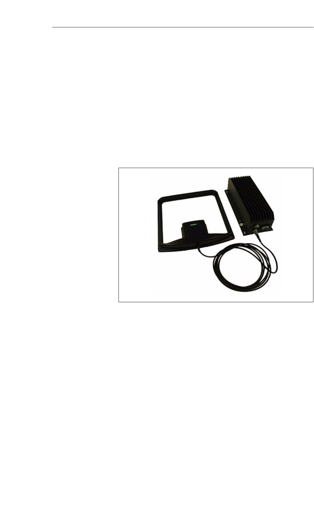
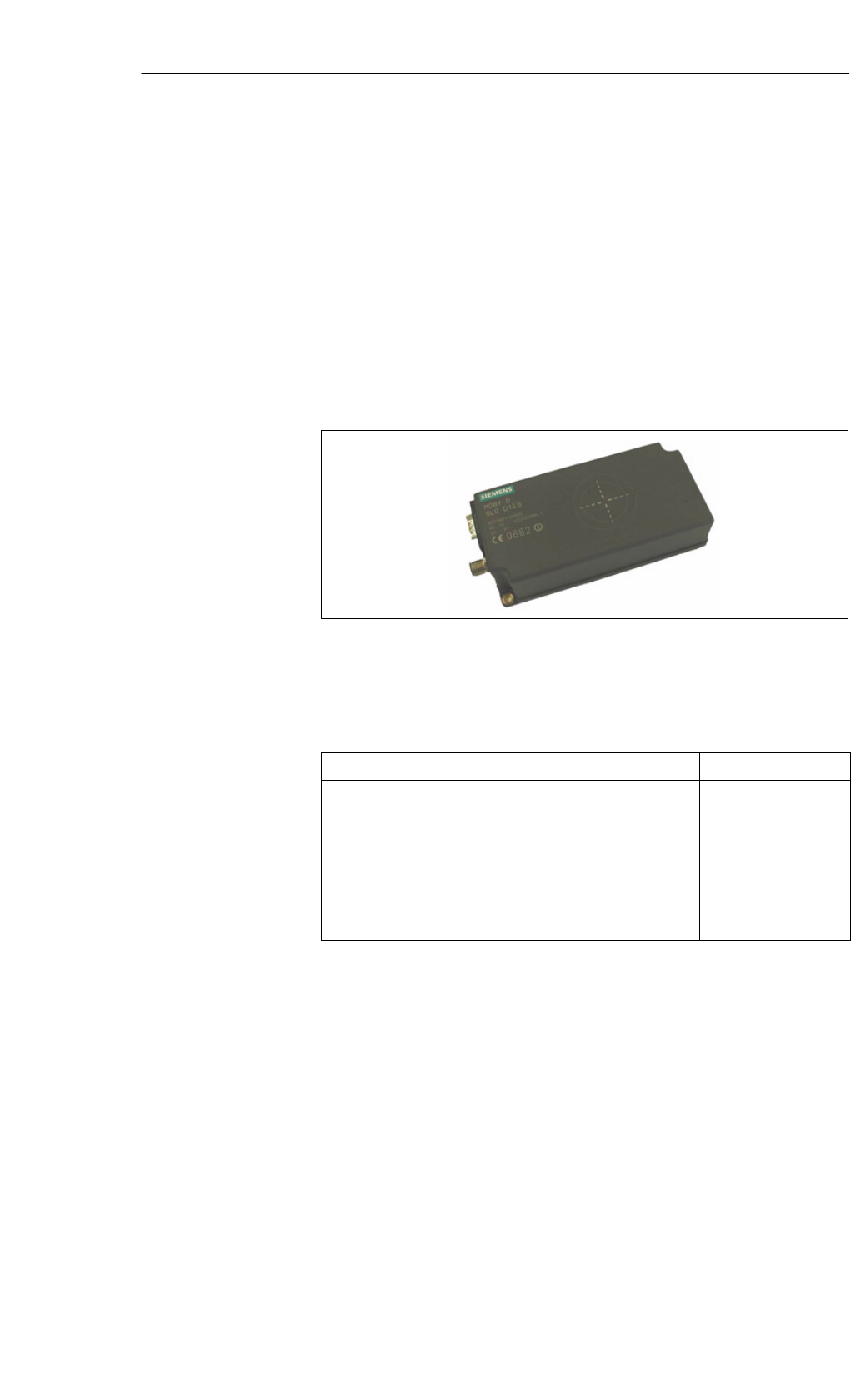
5.4 SLG D12
The SLG D12 is a medium-performance read/write device with a serial inter-
face and an integrated antenna, designed for a range of up to 150 mm. The
read/write device has an RS 232 serial interface (RS 422 interface on re-
quest), which permits communication with PCs or external PLCs.
For simple and rapid programming there is a C library available to the user
that can be used under Windows 9x, 2000, and NT. The SLG D12 is multitag
capable.
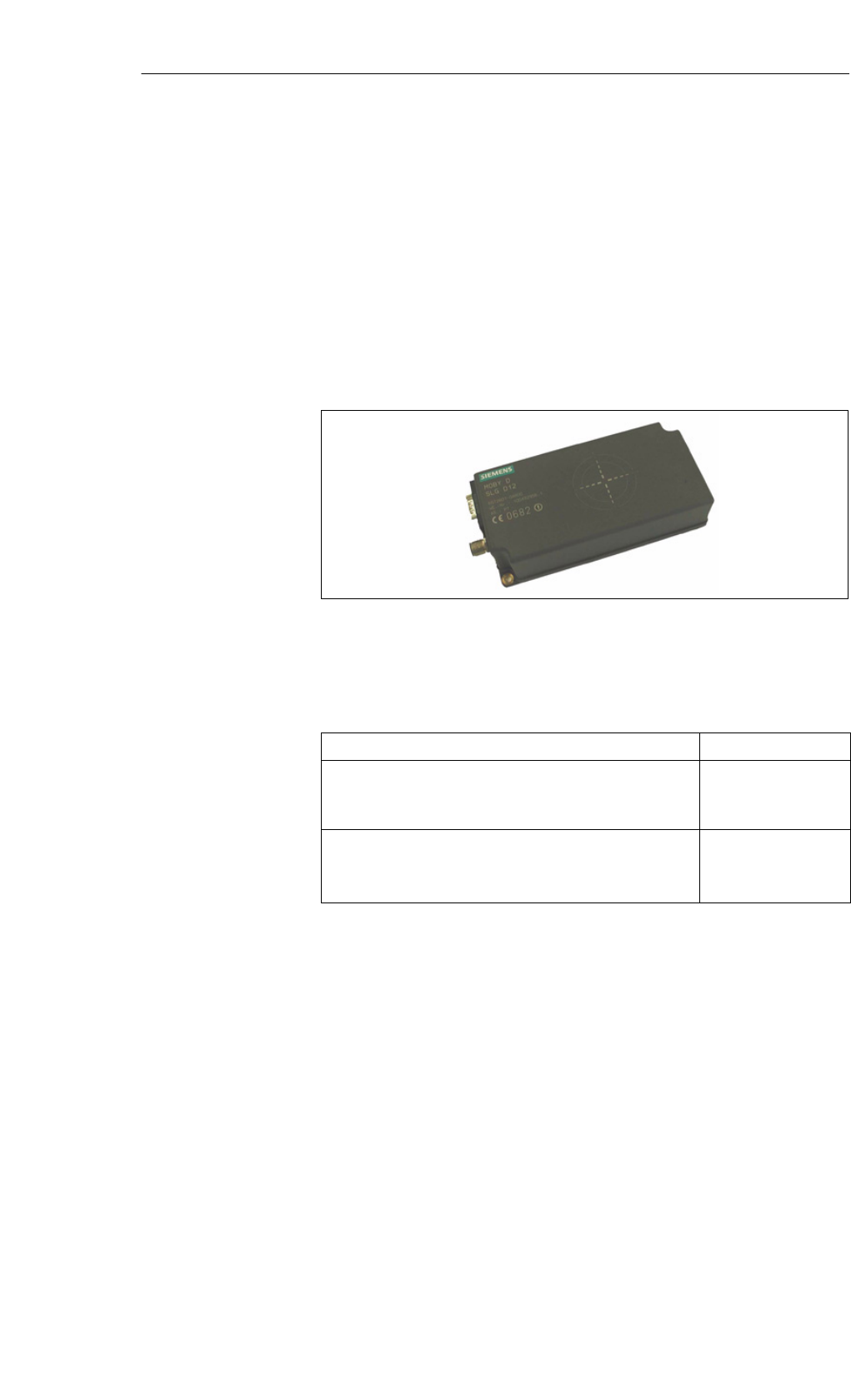
Figure 5-14 Read/write device SLG D12
Table 5-11 Ordering data for the SLG D12
Order No.
Read/write device SLG D12
With an RS 232 serial interface for standard PCs,
with an integrated antenna
6GT2 601-0AB00
Accessories:
MOBY wide-range power pack
Cables and connectors
6GT2 494-0AA00
See Section 3.6
Application
area
Ordering data
Read/Write Devices
5-24 MOBY D Configuration, Installation and Service Manual
(4) J31069-D0147-U001-A3-7618
Table 5-12 Technical data of the SLG D12
Inductive interface to MDS
Transmission frequency
Supported transponders
13.56 MHz
Transponder in accordance with ISO
15693
(e.g. I-Code, Tag-it, my-d)
Serial interface to user
Transmission protocol
Data transmission speed
Data backup
RS 232 (RS 422 on request)
Asynchronous 8 bit
9600 bps to 38.4 kbps
(adjustable)
CRC 16
SLG - MDS read/write distances Typically 150 mm (see field data)
Software functions
Programming
MDS: Read, write, initialize, access
rights, multitag
Windows 9x, 2000, and NT, with avai-
lable 32-bit DLL
Multitag Yes
Anti-collision speed Approx. 20 labels/s identifiable in pa-
rallel
Power supply
Nominal value
Permissible range
24 VDC
20 to 30 VDC
Current consumption
Operation
Transient making current
150 mA
600 mA
Line length, SLG – PC
With RS 232 30 m
Digital inputs/outputs None
Housing
Dimensions (L x B x H) in mm, without
connector
Color
Material
160 x 80 x 40
Anthracite
Plastic (PA 12)
Mounting 2 M5 screws
Ambient temperature
in operation
in transit and storage
–25 °C to +70 °C
–25 °C to +70 °C
Protection rating in accordance with
EN 60529
Shock in accordance with EN 60721-3-7
Class 7 M2
Total shock reply spectrum type II
Vibration in accordance with EN 60721-3-7
Class 7M2
IP65
30 g
1 g (9 to 200 Hz)/
1.5 g (200 to 500 Hz)
Technical data
Read/Write Devices
5-25
MOBY D Configuration, Installation and Service Manual
(4) J31069-D0147-U001-A3-7618
Table 5-12 Technical data of the SLG D12
Weight, approx. 500 g
Certifications Radio EN 300 330
CE
Safe for pacemakers
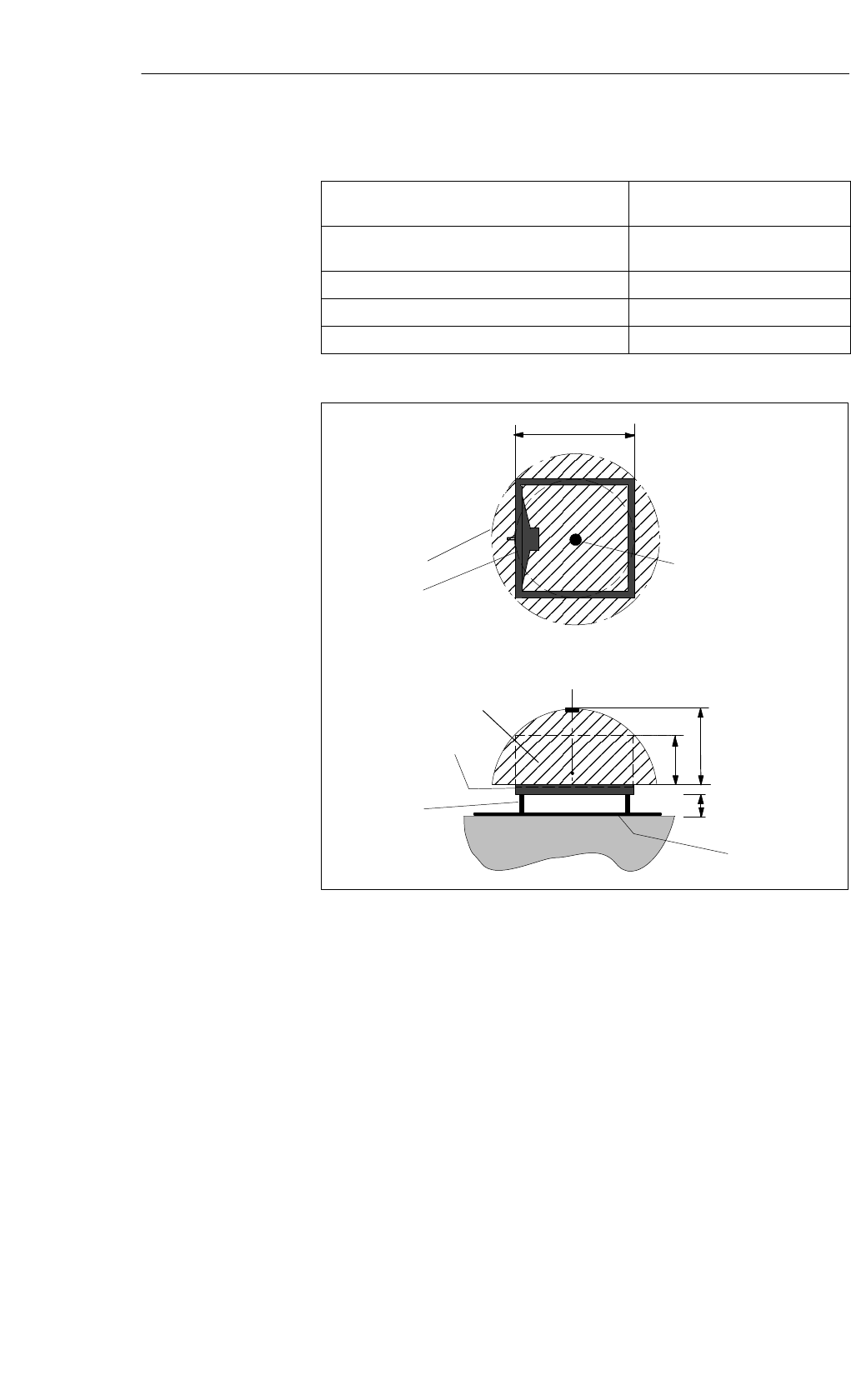
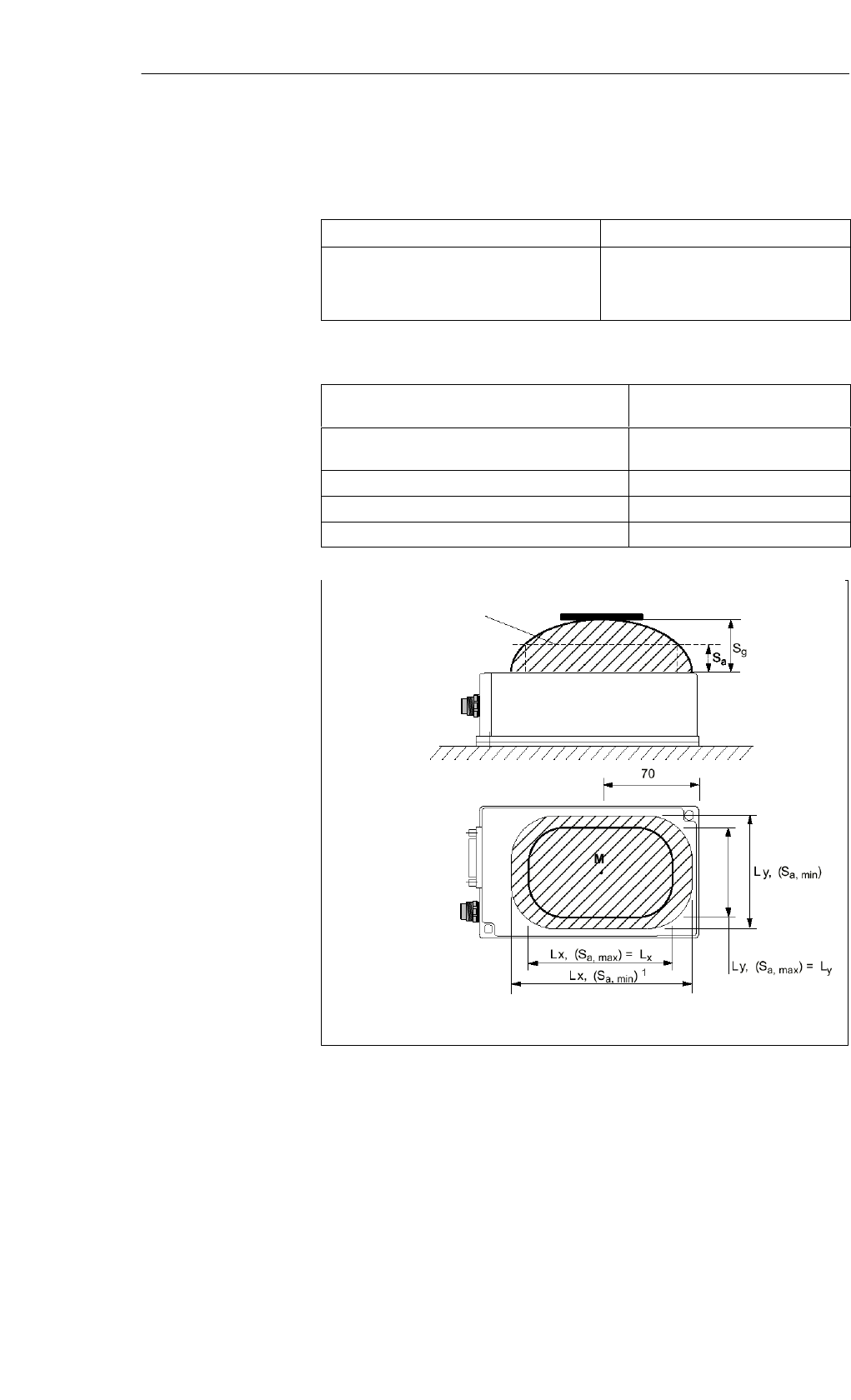
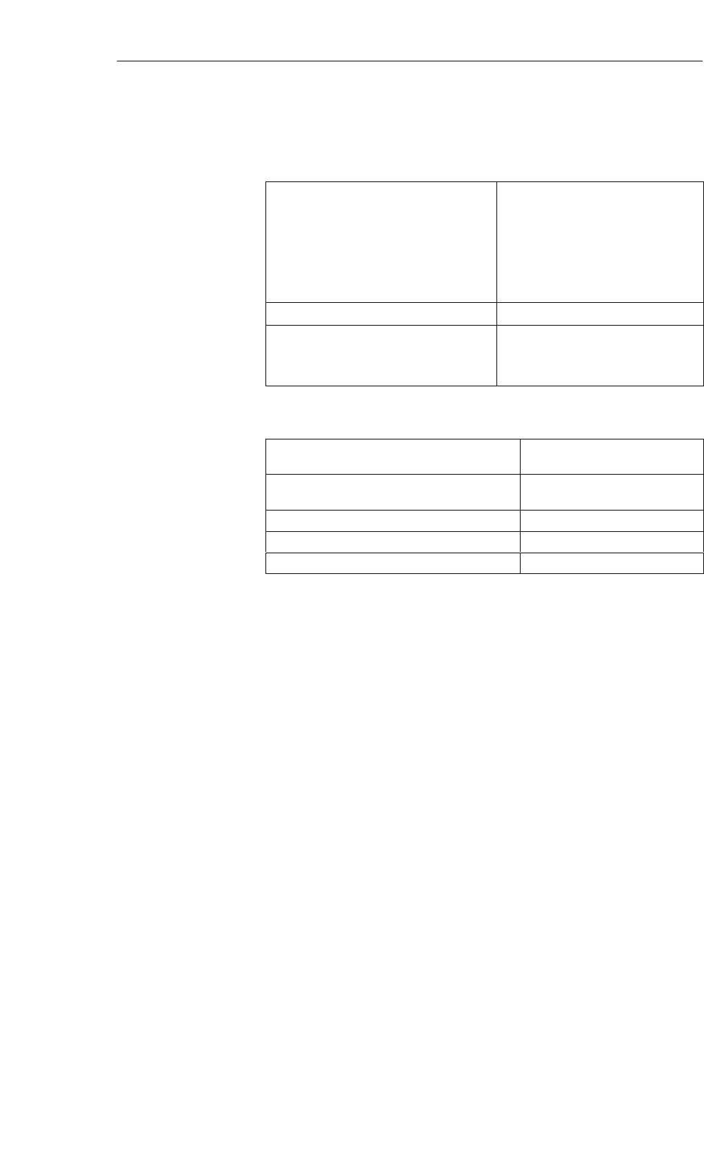
Table 5-13 Field data SLG D12
Limit distance (Sg)Max. 150 mm
(dependent on transponder)
Working distance (Sa)0 to 120 mm
(dependent on transponder)
Length of the transmission window (Ld)120 mm
Width of the transmission window (W) 48 mm
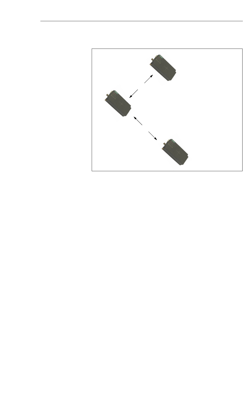
Minimum distance from SLG D12 to SLG D12 ≥ 500 mm
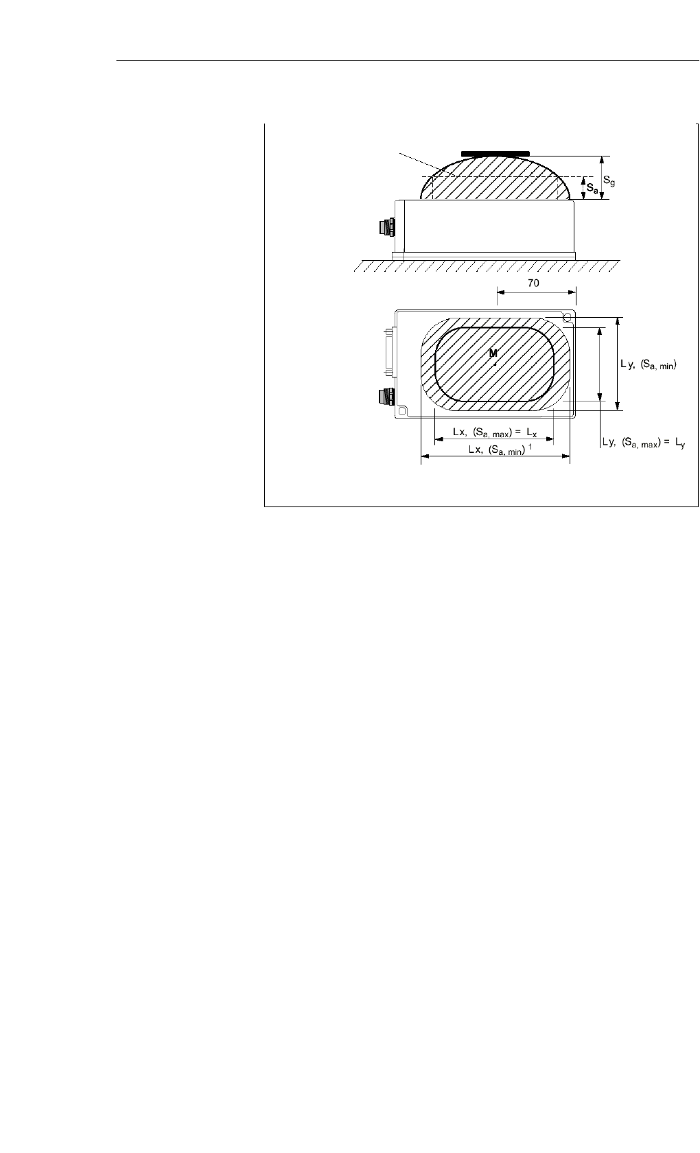
SLG D12
Transmission window Transponder Side view
Top view
Standard
Configuration:
lengthwise
x-axis (Lx)
1 At Sa, min the transmission window can be enlarged in comparison
to the standard configuration
1
Figure 5-15 Transmission window of the SLG D12
Field data
Transmission
window
Read/Write Devices
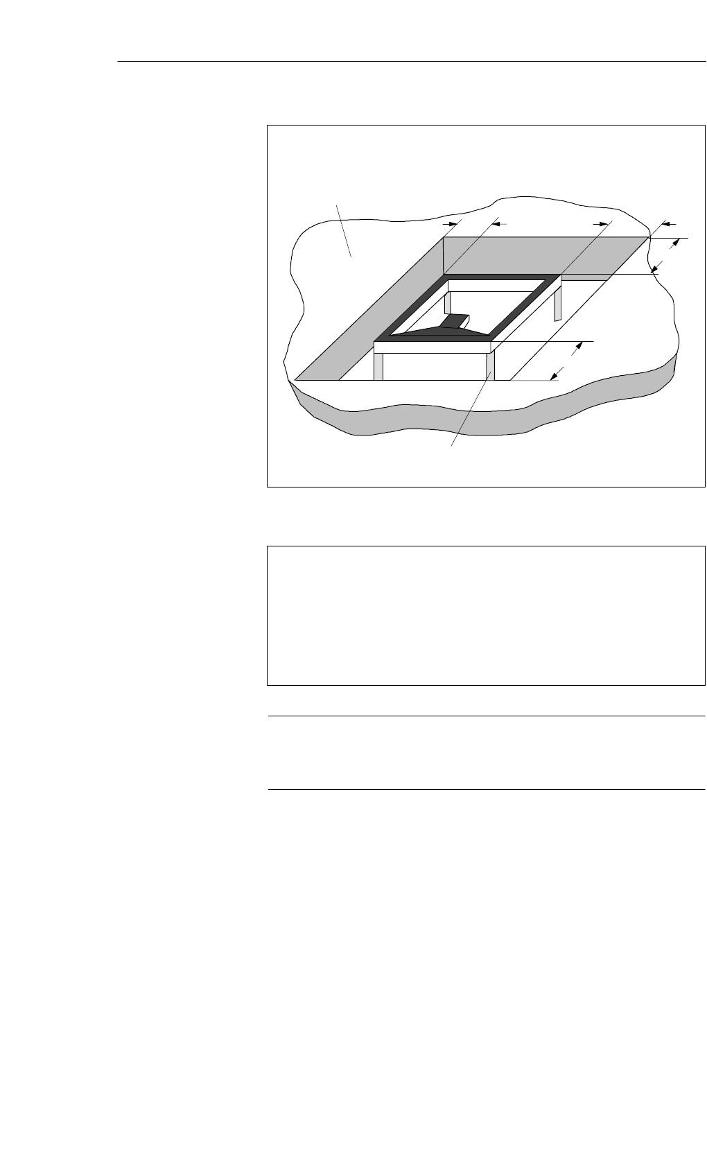
5-26 MOBY D Configuration, Installation and Service Manual
(4) J31069-D0147-U001-A3-7618
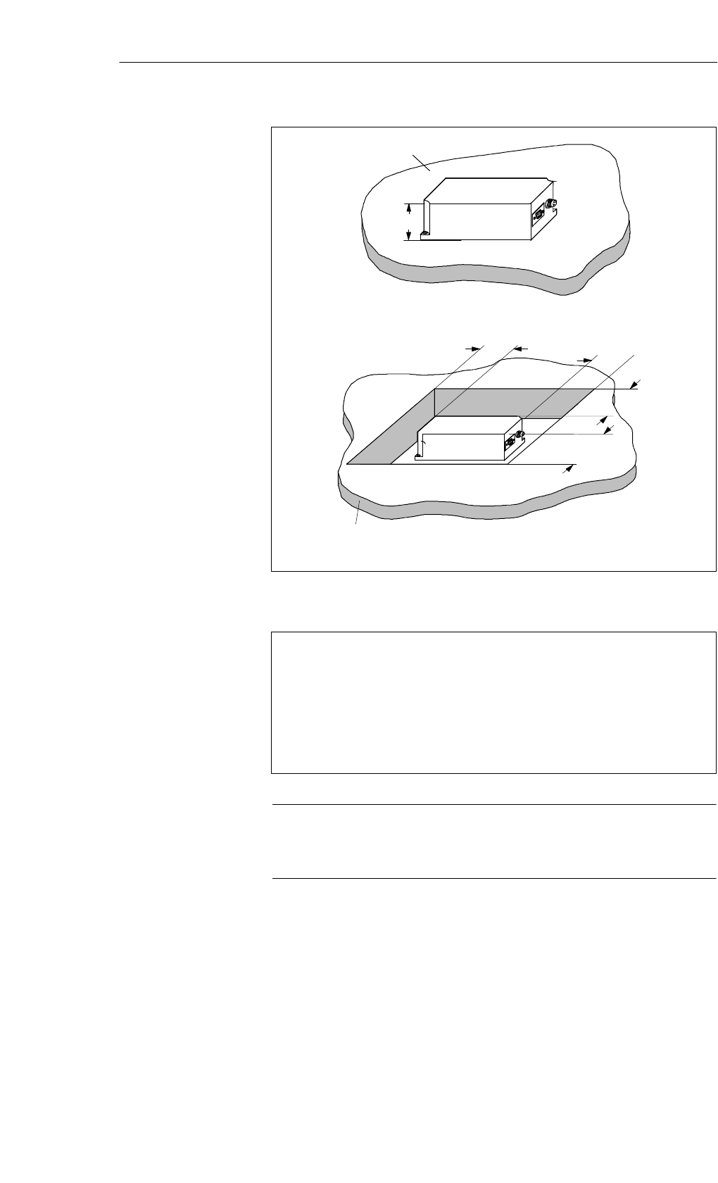
Metal
h = Physical height of the SLG = 40 mm
h
b
Metal
a, b = Metal-free distances = 50 mm
b
a
a
Figure 5-16 Metal-free space of SLG D12
Made in Germany
SIEMENS MOBY D SLG D12
FCC ID NXW-MOBYD-SLGD12
THIS DEVICE COMPLIES WITH PART 15 OF THE FCC RULES. OPERATION IS SUBJECT TO
THE FOLLOWING TWO CONDITIONS:
(1) THIS DEVICE MAY NOT CAUSE HARMFUL INTERFERENCE, AND (2) THIS DEVICE MUST
ACCEPT ANY INTERFERENCE RECEIVED, INCLUDING INTERFERENCE THAT MAY CAUSE
UNDESIRED OPERATION.
Caution
Any changes or modifications not expressly approved by the party responsi-
ble for compliance could void the user’s authority to operate the equipment.
Metal-free space
FCC information
Read/Write Devices

5-27
MOBY D Configuration, Installation and Service Manual
(4) J31069-D0147-U001-A3-7618
Distance D ≥ 0.5 m
D
D
Figure 5-17 Distance D: SLG D12
Definition of
distance D
Read/Write Devices
5-28 MOBY D Configuration, Installation and Service Manual
(4) J31069-D0147-U001-A3-7618
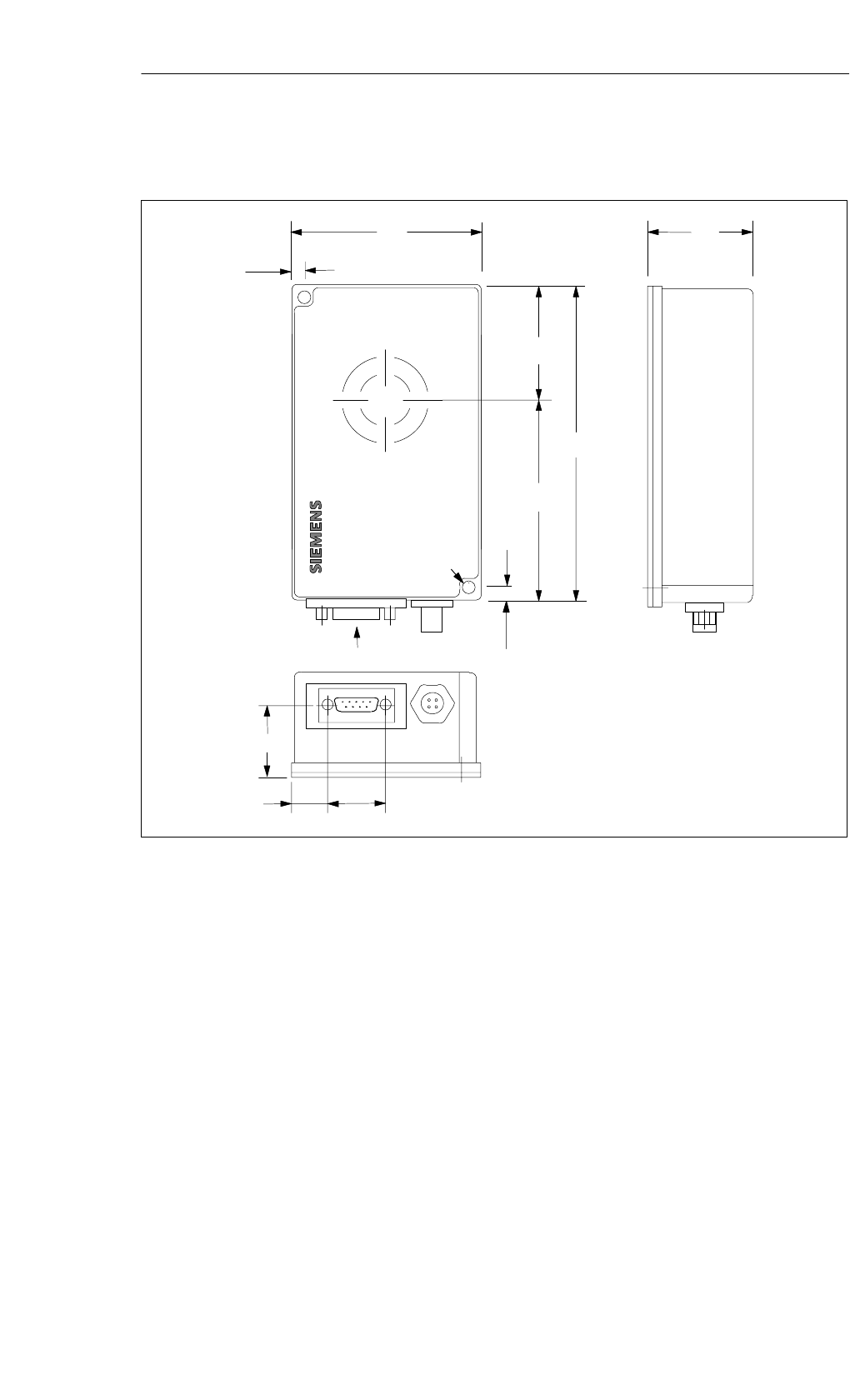
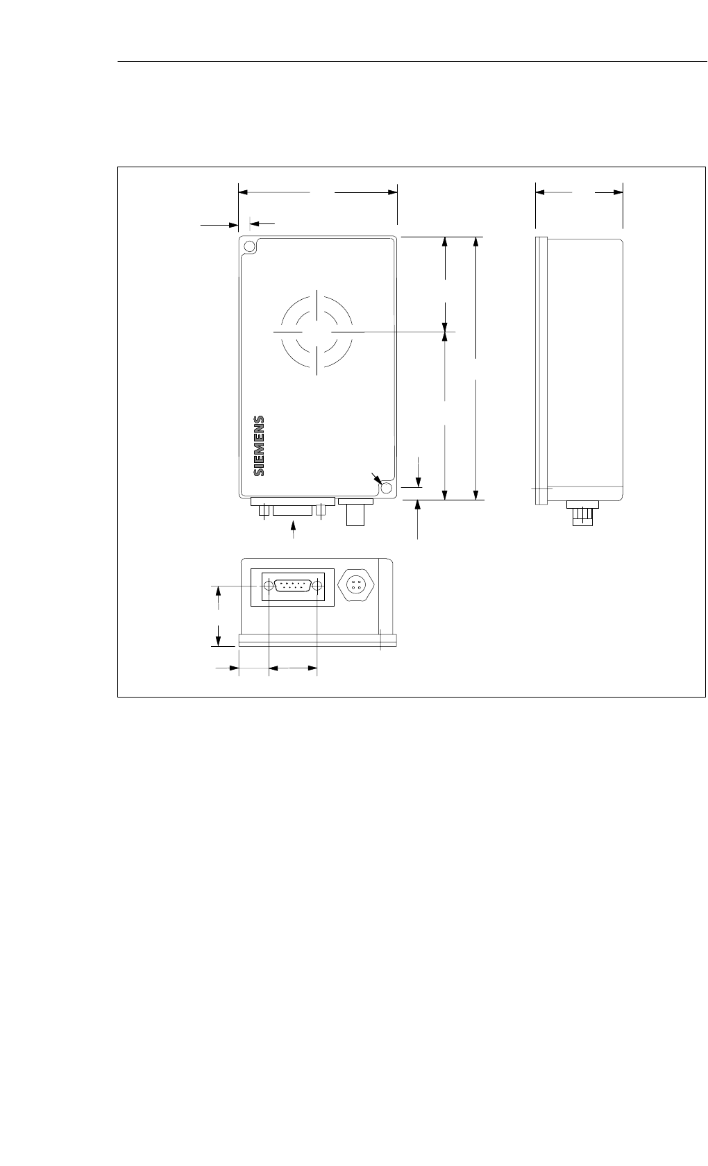
90
5
5
80 40
X
Y
160
70
A
View A
26
12 33
∅ 5.5
Figure 5-18 Dimensioned drawing of the SLG D12
Dimensions
(in mm)
Read/Write Devices
5-29
MOBY D Configuration, Installation and Service Manual
(4) J31069-D0147-U001-A3-7618
5.5 SLG D10S ANT D5
The SLG D10S ANT D5 is a high-performance read/write device with a se-
rial interface and a separate antenna, designed specifically for storage, logi-
stics, and distribution applications. It is designed for a range of up to 600 mm
(depending on the label). The read/write device has an RS 422 serial inter-
face, which permits communication via interface modules (ASM 452,
ASM 473 und ASM 475) to the SIMATIC S7 or PROFIBUS-DPV1.
FC 45 is available to the user for simple and rapid programming.
Due to the high degree of protection (IP65) and the use of high-quality mate-
rials, the SLG D10S ANT D5 ensures trouble-free use even under the most
extreme industrial conditions.
Figure 5-19 Read/write device SLG D10S ANT D5
Application
area
Read/Write Devices
5-30 MOBY D Configuration, Installation and Service Manual
(4) J31069-D0147-U001-A3-7618
Table 5-14 Ordering data for the SLG D10S ANT D5
Order No.
Read/write device SLG D10S ANT D5
With an RS 422 serial interface
for connecting to an ASM 452, ASM 473, and ASM 475,
with separate antenna
6GT2 602-0AA00
Accessories:
ANT D5 spacer kit
MOBY wide-range power pack
Cables and connectors
6GT2 690-0AB00
6GT2 494-0AA00
See Section 3.6
Table 5-15 Technical data of the SLG D10S ANT D5
Inductive interface to MDS
Transmission frequency
Supported transponders
13.56 MHz
SI-Code1
(e. g. MDS D139, MDS D160)
STransponder in accordance with ISO
15693
(e. g. I-Code SLI, Tag-it HFI,
my-d SRF 55V10P)
Serial interface to user
Transmission protocol
Data transmission speed
Data backup
RS 422
Asynchronous 8 bit
19.2 bps to 115.2 kbps
(ASM-dependent)
CRC 16
Output power 4 W
SLG-MDS read/write distances Typically 450 mm (see field data)1
Software functions Read, write, initialize MDS
The command Repeat is not permissible.
The user has a maximum buffer of
256 bytes in the SLG for pipelining.
Hence, a command string can only con-
tain as many individual commands as
such that the sum of the header and user
data fields lengths of the individual mes-
sages does not exceed this value. The
FC 45 limits the length of the user data
fields to 233 bytes per individual mes-
sage.
Programming
Transmission protocol
FC 45
3964 R
Multitag in preparation
Power supply 24 VDC + 5%
Ordering data
Technical data
Read/Write Devices
5-31
MOBY D Configuration, Installation and Service Manual
(4) J31069-D0147-U001-A3-7618
Table 5-15 Technical data of the SLG D10S ANT D5
Current consumption
Operation
Transient making current
0.9 A
2.8 A/50 ms
Line length (SLG – SIMATIC S7)
With RS 422
Antenna line length
300 m
3.60 m
Digital inputs/outputs None
Housing
Dimensions (in mm)
For antenna [L x W x H]
For electronic components
[L x W x H]
Color Antenna
SLG housing
Material Antenna
SLG housing
Connector
Antenna (can be connected to the
SLG)
340 x 325 x 38
320 x 145 x 100 (without connector)
Black
Anthracite
Plastic ASA
Aluminum
TNC connector
Mounting of SLG
Mounting of antenna
4 M6 screws
4 M5 screws
Ambient temperature
in operation
in transit and storage
–20 °C to +55 °C
–25 °C to +70 °C
Protection rating in accordance with
EN 60529
SLG and antenna
Shock in accordance with EN 60721-3-7
Class 7M2
Total shock response spectrum type II
Vibration in accordance with EN
60721-3-7 Class 7M2
IP65
30 g
1 g (9 to 200 Hz)/
1.5 g (200 to 500 Hz)
Weight, approx.
SLG
Antenna
3500 g
1000 g
Certifications Radio EN 300 330
CE
Safe for pacemakers
1 To ensure optimal field data in a metallic environment, the ANT D5 is calibrated at
the factory at a distance of 100 mm from metal.
Read/Write Devices

5-32 MOBY D Configuration, Installation and Service Manual
(4) J31069-D0147-U001-A3-7618
Caution
The antenna cable is prepared in advance. If the cable is changed, the war-
ranty and CE marking become invalid.
Note
After the ANT D5 antenna is removed from the SLG and connected again
(screwed on), an init_run must be executed.
Read/Write Devices

5-33
MOBY D Configuration, Installation and Service Manual
(4) J31069-D0147-U001-A3-7618
Table 5-16 Field data of the SLG D10S ANT D5
Limit distance (Sg)Max. 450 mm
(dependent on transponder)
Working distance (Sa)0 to 380 mm
(dependent on transponder)
Length of the transmission window (Ld)320 mm
Width of the transmission window (W) 128 mm
Minimum distance from ANT D5 to ANT D5 ≥ 2 m
Sg
Side view
Transmission window
Top view
Sa
Ld
100
Metal plate
ANT D5
Sa, min.1
Sa, max.
Sg
1 At Sa, min the transmission window increases
Spacing kit
Figure 5-20 Transmission window with the SLG D10S ANT D5
Field data
Transmission
window
Read/Write Devices

5-34 MOBY D Configuration, Installation and Service Manual
(4) J31069-D0147-U001-A3-7618
Metal-free space with flush mounting
a = 150 mm
a
Metal
a
a
a
h = 100 mm (non-metallic spacers)
Figure 5-21 Metal-free space for the SLG D10S ANT D5
Made in Germany
SIEMENS MOBY D SLG D10S
FCC ID NXW-MOBYD-SLGD10
THIS DEVICE COMPLIES WITH PART 15 OF THE FCC RULES. OPERATION IS SUBJECT TO
THE FOLLOWING TWO CONDITIONS:
(1) THIS DEVICE MAY NOT CAUSE HARMFUL INTERFERENCE, AND (2) THIS DEVICE MUST
ACCEPT ANY INTERFERENCE RECEIVED, INCLUDING INTERFERENCE THAT MAY CAUSE
UNDESIRED OPERATION.
Caution
Any changes or modifications not expressly approved by the party responsi-
ble for compliance could void the user’s authority to operate the equipment.
Metal-free space
FCC information
Read/Write Devices
5-35
MOBY D Configuration, Installation and Service Manual
(4) J31069-D0147-U001-A3-7618
Distance D ≥ 2 m
D
D
Figure 5-22 Distance D: SLG D10S ANT D5
Definition of the
distance D
Read/Write Devices
5-36 MOBY D Configuration, Installation and Service Manual
(4) J31069-D0147-U001-A3-7618
Anti-kink protection
bendable in all directions
Minimal bending
radius: 20 mm
Cable length 3.5 m
325
145
10
7
125
A
View A
100
52,5
Note:
The SLG must be grounded using the grounding screw provided. 1
1
25
300
31
25
60
7
4 x ∅ 5.5
320
290
340
Figure 5-23 Dimensioned drawing of the SLG D10S ANT D5
Note
In order to ensure optimal field data in surroundings where there is metal as
well, the ANT D5 is calibrated at the factory at a distance of 100 mm from
metal.
see Chapter 5.2
Dimensions
(in mm)
MOBY D ANT D5
spacer kit
Read/Write Devices
5-37
MOBY D Configuration, Installation and Service Manual
(4) J31069-D0147-U001-A3-7618
5.6 SLG D11S ANT D5
The SLG D11 ANT D5 is a medium-performance read/write device with a
serial interface and a separate antenna, designed specifically for storage, logi-
stics, and distribution applications. It is designed for a range of up to 300 mm
(depending on the label).
The read/write device has an RS 422, serial interface, which permits commu-
nication via interface modules (ASM 452, ASM 473 und ASM 475) to the
SIMATIC S7 or PROFIBUS-DPV1.
FC 45 is available to the user for simple and rapid programming.
A robust housing and the high degree of protection (IP65) permit deployment
in the most severe industrial environments.
Figure 5-24 Read/write device SLG D11S ANT D5
Table 5-17 SLG D11S ANT D5 ordering information
Order No.
Read/write device SLG D11S ANT D5
With an RS 422 serial interface for connecting to an
ASM 452, ASM 473 and ASM 475,
with separate antenna
6GT2 602-0AC00
Accessories:
Spacer kit for ANT D5
MOBY DC 24 V wide-range power pack
Cables and connectors
6GT2 690-0AB00
6GT2 494-0AA00
See Section 3.6
Application
area
Ordering
information
Read/Write Devices
5-38 MOBY D Configuration, Installation and Service Manual
(4) J31069-D0147-U001-A3-7618
Table 5-18 SLG D11S ANT D5 technical data
Inductive interface to MDS
Transmission frequency
Supported transponders
13.56 MHz
SI-Code1
(e. g. MDS D139, MDS D160)
STransponder in accordance with
ISO 15693
(e. g. I-Code SLI, Tag-it HFI,
my-d SRF 55V10P)
Serial interface to user
Transmission protocol
Data transmission speed
Data backup
RS 422
Asynchronous 8 bit
19.2 kBaud
CRC 16
Output power 1 W
SLG – MDS read/write distances Typically 300 mm (see field data)1
Software functions MDS read, write, initialize
Command strings are not permitted.
The Repeat command has not been
implemented.
The greatest possible length of the
user data field in a command is
233 bytes.
Programming
Transmission protocol
FC 45
3964 R
Multitag No
Power supply
Operation
Permissible range
24 VDC
20 V to 30 VDC
Current consumption
Operation
Transient making current
150 mA
600 mA
Line length (SLG – SIMATIC S 7)
With RS 422
Antenna line length
300 m
3.60 m
Digital inputs/outputs None
Technical data
Read/Write Devices
5-39
MOBY D Configuration, Installation and Service Manual
(4) J31069-D0147-U001-A3-7618
Table 5-18 SLG D11S ANT D5 technical data
Housing
Dimensions (in mm)
For antenna [L x W x H]
for the electronics
[L x B x H]
Color Antenna
SLG housing
Material Antenna
SLG housing
Connector
Antenna (can be connected to the SLG)
340 x 325 x 38
160 x 80 x 40 (without connector)
Black
Anthracite
Plastic ASA
Plastic (PA 12)
TNC connector
Mounting of SLG
Mounting of antenna
2 M5 screws
4 M5 screws
Ambient temperature
in operation
in transport and storage
–25 °C to +70 °C
–25 °C to +70 °C
Protection rating in accordance with EN 60529
SLG and antenna
Shock in accordance with
EN 60721-3-7 Class 7M2
Total shock reply spectrum type II
Vibration in accordance with EN 60721-3-7
Class 7M2
IP65
30 g
1 g (9 to 200 Hz)/
1.5 g (200 to 500 Hz)
Weight, approx.
SLG
Antenna
Approx. 600 g
Approx. 1000 g
Certifications Radio EN 300 330
CE
Safe for pacemakers
1 To ensure optimal field data in a metallic environment, the ANT D5 is calibrated at
the factory at a distance of 100 mm from metal.
Table 5-19 SLG D11S ANT D5 field data
Limit distance (Sg)Max. 300 mm
(dependent on transponder)
Working distance (Sa)0 to 240 mm
(dependent on transponder)
Length of the transmission window (Ld)300 mm
Field data
Read/Write Devices
5-40 MOBY D Configuration, Installation and Service Manual
(4) J31069-D0147-U001-A3-7618
Table 5-19 SLG D11S ANT D5 field data
Width of the transmission window (W) 120 mm
Minimum distance from ANT D5 to ANT D5 ≥ 2 m
Sg
Side view
Transmission window
Top view
Sa
Ld
100
Metal plate
ANT D5
Sa, min.1
Sa, max.
Sg
1 At Sa, min the transmission window increases
Spacing kit
Figure 5-25 SLG D11S ANT D5 transmission window
Transmission
window
Read/Write Devices

5-41
MOBY D Configuration, Installation and Service Manual
(4) J31069-D0147-U001-A3-7618
Metal-free space with flush mounting
a = 150 mm
a
Metal
a
a
a
h = 100 mm (non-metallic spacers)
Figure 5-26 SLG D11S ANT D5 metal-free space
Made in Germany
SIEMENS MOBY D SLG D11S
FCC ID NXW-MOBYD-SLGD11
THIS DEVICE COMPLIES WITH PART 15 OF THE FCC RULES. OPERATION IS SUBJECT TO
THE FOLLOWING TWO CONDITIONS:
(1) THIS DEVICE MAY NOT CAUSE HARMFUL INTERFERENCE, AND (2) THIS DEVICE MUST
ACCEPT ANY INTERFERENCE RECEIVED, INCLUDING INTERFERENCE THAT MAY CAUSE
UNDESIRED OPERATION.
Caution
Any changes or modifications not expressly approved by the party responsi-
ble for compliance could void the user’s authority to operate the equipment.
Metal-free space
FCC information
Read/Write Devices
5-42 MOBY D Configuration, Installation and Service Manual
(4) J31069-D0147-U001-A3-7618
D
D
Distance D ≥ 2 m
Figure 5-27 Distance D: SLG D11S ANT D5
Definition of the
distance D
Read/Write Devices
5-43
MOBY D Configuration, Installation and Service Manual
(4) J31069-D0147-U001-A3-7618
∅5.5
Anti-kink protection
bendable in all directions
Minimal bending
radius: 20 mm
Cable length 3.5 m
325
300
731
340
5
80
160
A
View A
26
40
12 33
5
Ferrite
4 x ∅ 5.5
100
Figure 5-28 SLG D11S ANT D5 dimensioned drawing
Note
In order to ensure optimal field data in surroundings where there is metal as
well, the ANT D5 is calibrated at the factory at a distance of 100 mm from
metal.
See Chapter 5.2
Dimensions (in
mm)
MOBY D ANT D5
spacer kit
Read/Write Devices
5-44 MOBY D Configuration, Installation and Service Manual
(4) J31069-D0147-U001-A3-7618
5.7 SLG D12S
The SLG D12 is a medium-performance read/write device with a serial inter-
face and an integrated antenna, designed for a range of up to 150 mm (depen-
ding upon the label). The read/write device has an RS 422 serial interface,
which permits communication via interface modules (ASM 452, ASM 473
und ASM 475) to the SIMATIC S7 or PROFIBUS-DP-V1.
FC 45 is available to the user for simple and rapid programming.
A robust housing and the high degree of protection (IP65) permit deployment
in the most severe industrial environments.
Figure 5-29 SLG D12S read/write device
Table 5-20 SLG D12S ordering information
Order No.
SLG D12S read/write device
With an RS 422 serial interface for connecting to an
ASM 452, ASM 473 und ASM 475,
with integrated antenna
6GT2 602-0AB00
Accessories:
MOBY DC 24 V wide-range power pack
Cables and Connectors
6GT2 494-0AA00
See Section 3.6
Application
area
Ordering
information
Read/Write Devices
5-45
MOBY D Configuration, Installation and Service Manual
(4) J31069-D0147-U001-A3-7618
Table 5-21 SLG D12S technical data
Inductive interface to MDS
Transmission frequency
Supported transponders
13.56 MHz
SI-Code1
(e. g. MDS D139, MDS D160)
STransponder in accordance with
ISO 15693
(e. g. I-Code SLI, Tag-it HFI,
my-d SRF 55V10P)
Serial interface to user
Transmission protocol
Data transmission speed
Data backup
RS 422
Asynchronous 8 bit
19.2 kBaud
CRC 16
Output power 1 W
SLG – MDS read/write distances Typically 150 mm (see field data)
Software functions MDS read, write, initialize
Command strings are not permitted.
The Repeat command has not been im-
plemented.
The greatest possible length of the user
data field in a command is 233 bytes.
Programming
Transmission protocol
FC 45
3964 R
Multitag No
Power supply
Operation
Permissible range
24 VDC
20 V to 30 VDC
Current consumption
Operation
Transient making current
150 mA
600 mA
Line length (SLG – SIMATIC S 7)
With RS 422 300 m
Digital inputs/outputs None
Housing
Dimensions (L x B x H) in mm, without
connectors
Color
Material
160 x 80 x 40
Anthracite
Plastic (PA 12)
Mounting 2 M5 screws
Ambient temperature
in operation
in transit and storage
–25 °C to +70 °C
–25 °C to +70 °C
Technical data
Read/Write Devices
5-46 MOBY D Configuration, Installation and Service Manual
(4) J31069-D0147-U001-A3-7618
Table 5-21 SLG D12S technical data
Protection rating in accordance with
EN 60529
Shock in accordance with EN 60721-3-7
Class 7 M2
Total shock response spectrum Type II
Vibration in accordance with EN 60721-3-7
Class 7M2
IP65
30 g
1 g (9 to 200 Hz)/
1.5 g (200 to 500 Hz)
Weight, approx. 600 g
Certifications Radio EN 300 330
CE
Safe for pacemakers
Table 5-22 SLG D12S field data
Limit distance (Sg)Max. 150 mm
(dependent on transponder)
Working distance (Sa)0 to 120 mm
(dependent on transponder)
Length of the transmission window (Ld)120 mm
Width of the transmission window (W) 48 mm
Minimal distance from SLG D12S to SLG D12S ≥ 500 mm
Field data
Read/Write Devices
5-47
MOBY D Configuration, Installation and Service Manual
(4) J31069-D0147-U001-A3-7618
SLG D12S
Transmission window Transponder Side view
Top view
Standard
Configuration:
lengthwise
x-axis (Lx)
1 At Sa, min the transmission window can be enlarged in comparison
to the standard configuration
1
Figure 5-30 Transmission window of the SLG D12S
Transmission
window
Read/Write Devices

5-48 MOBY D Configuration, Installation and Service Manual
(4) J31069-D0147-U001-A3-7618
Metal
h = Physical height of the SLG = 40 mm
h
b
Metal
a, b = Metal-free distances = 50 mm
b
a
a
Figure 5-31 SLG D12S metal-free space
Made in Germany
SIEMENS MOBY D SLG D12S
FCC ID NXW-MOBYD-SLGD12
THIS DEVICE COMPLIES WITH PART 15 OF THE FCC RULES. OPERATION IS SUBJECT TO
THE FOLLOWING TWO CONDITIONS:
(1) THIS DEVICE MAY NOT CAUSE HARMFUL INTERFERENCE, AND (2) THIS DEVICE MUST
ACCEPT ANY INTERFERENCE RECEIVED, INCLUDING INTERFERENCE THAT MAY CAUSE
UNDESIRED OPERATION.
Caution
Any changes or modifications not expressly approved by the party responsi-
ble for compliance could void the user’s authority to operate the equipment.
Metal-free space
FCC information
Read/Write Devices
5-49
MOBY D Configuration, Installation and Service Manual
(4) J31069-D0147-U001-A3-7618
Distance D ≥ 0.5 m
D
D
Figure 5-32 Distance D: SLG D12S
Definition of the
Distance D
Read/Write Devices
5-50 MOBY D Configuration, Installation and Service Manual
(4) J31069-D0147-U001-A3-7618
90
5
5
80 40
X
Y
160
70
A
View A
26
12 33
∅ 5.5
Figure 5-33 Dimensioned drawing SLG D12S
Dimensions (in
mm)
Read/Write Devices