Siemens MOBYI-SLG41CN Inductive TAG System User Manual MOBY I en A71
Siemens AG Inductive TAG System MOBY I en A71
Siemens >
Users Manual
Table of Contents
General 1
Introduction to MOBY I 2
Configuration and Mounting
Guidelines 3
Mobile Data Memories 4
Read/Write Devices 5
Interfaces 6
Accessories 7
Documentation A
Error Messages B
ASCII Table C
Compatibility D
Published in January, 2002
6GT2 097-4BA00-0EA2
Configuration, Installation and
Service
Manual
MOBYR I
ii
This manual contains notices which you should observe to ensure your own personal safety, as
well as to protect the product and connected equipment. These notices are highlighted in the
manual by a warning triangle and are marked as follows according to the level of danger.
!Danger
indicates that death, severe personal injury or substantial property damage will result if proper
precautions are not taken.
!Warning
indicates that death, severe personal injury or substantial property damage can result if proper
precautions are not taken.
!Caution
indicates that minor personal injury or property damage can result if proper precautions are not taken.
Note
draws your attention to particularly important information on the product, handling the product, or
to a particular part of the documentation.
Only qualified personnel should be allowed to install and work on this equipment. For the pur-
poses of the safety notes contained in this manual; qualified persons are defined as persons who
are authorized to commission, to ground, and to tag circuits, equipment, and systems in accor-
dance with established safety practices and standards.
Note the following.
!Warning
This device and its components may only be used for the applications described in the catalog or the
technical description, and only in connection with devices or components from other manufacturers
which have been approved or recommended by Siemens.
This product can only function correctly and safely if it is transported, stored, set up, and installed
correctly, and operated and maintained as recommended.
MOBYR, SIMATICR and SINECR are registered trademarks of SIEMENS AG.
Some of the other designations used in this documentation are also registered trademarks; the
owner’s rights may be violated if they are used by third parties for their own purposes.
We have checked the contents of this manual for agreement with the
hardware and software described. Since deviations cannot be pre-
cluded entirely, we cannot guarantee full agreement. However, the
data in this manual are reviewed regularly and any necessary cor-
rections included in subsequent editions. Suggestions for improve-
ment are welcomed.
E Siemens AG 1997, 1998, 1999, 2000, 2001, 2002
Technical data subject to change
Disclaimer of LiabilityCopyright E Siemens AG 1997 All rights reserved
The reproduction, transmission or use of this document or its
contents is not permitted without express written authority.
Offenders will be liable for damages. All rights, including rights
created by patent grant or registration of a utility model or design, are
reserved.
Siemens AG
Automation and Drives
Systems Engineering
Postfach 23 55, D-90713 Fuerth
Siemens Aktiengesellschaft Order No. 6GT2 097-4BA00-0EA2
Safety Guidelines
Qualified Personnel
Correct Usage
Trademarks
3-1
MOBY I Configuration, Installation and Service Manual
(4) J31069-D0033-U001-A7.1-7618
Configuration and Mounting Guidelines 3

3-2 MOBY I Configuration, Installation and Service Manual
(4) J31069-D0033-U001-A7.1-7618
3.1 Basic Requirements
!Warning
Do not make changes to the devices.
Violation will invalidate interference emission certification (BZT, FCC), CE
and the manufacturer’s warranty.
Note
Any unauthorized modifications to this device could void the user’s author-
ity to operate the equipment.
To choose the correct MOBY I components, apply the following criteria to
your particular application.
STransmission distance (i.e., read/write distance)
SThe amount of data to be transferred
SMetal-free spaces for MDS and SLG
SStatic or dynamic transmission of the data
SSpeed for dynamic transmission
STolerances of the tracking
SEnvironmental conditions (e.g., moisture, temperature, chemical in-
fluences and so on)
FCC Compliance
Statement
Configuration and Mounting Guidelines
5-12 MOBY I Configuration, Installation and Service Manual
(4) J31069-D0033-U001-A7.1-7618
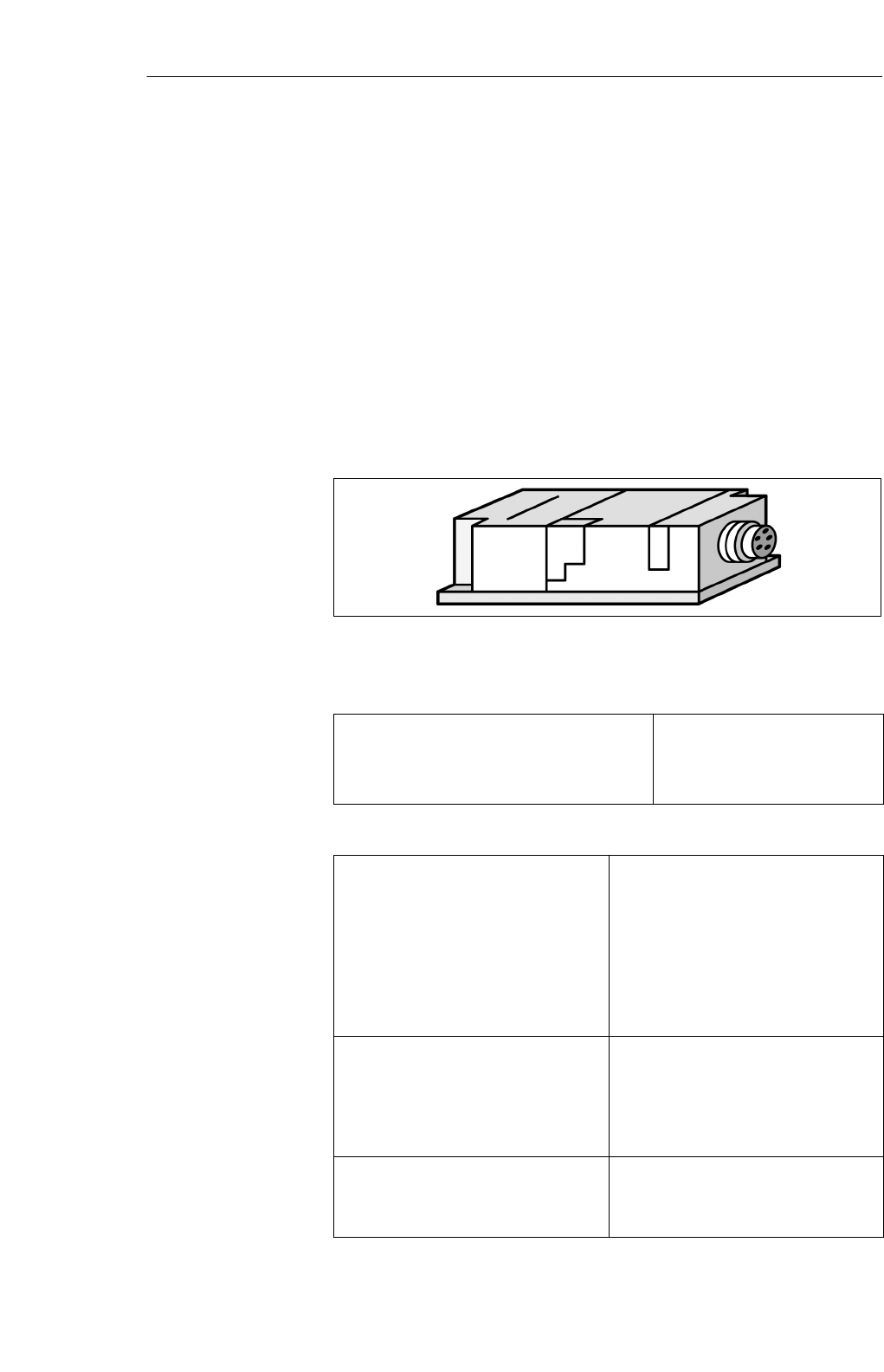
5.4 SLG 41/SLG 41-S
The SLG 41 is a low-end read/write device. It is particularly suitable for use
when the MDS conveyor system (e.g., pallets) can be physically positioned
relatively precisely. The swivel head of the SLG 41 makes it very adaptable
to the transportation system.
In dynamic operation, only a small amount of data can be read or written
between SLG 41 and MDS.
In contrast to the SLG 41, the antenna of the SLG 41-S is rotated by 90° in
the swivel head so that all positions of the transmission window can be im-
plemented.
Figure 5-12 SLG 41
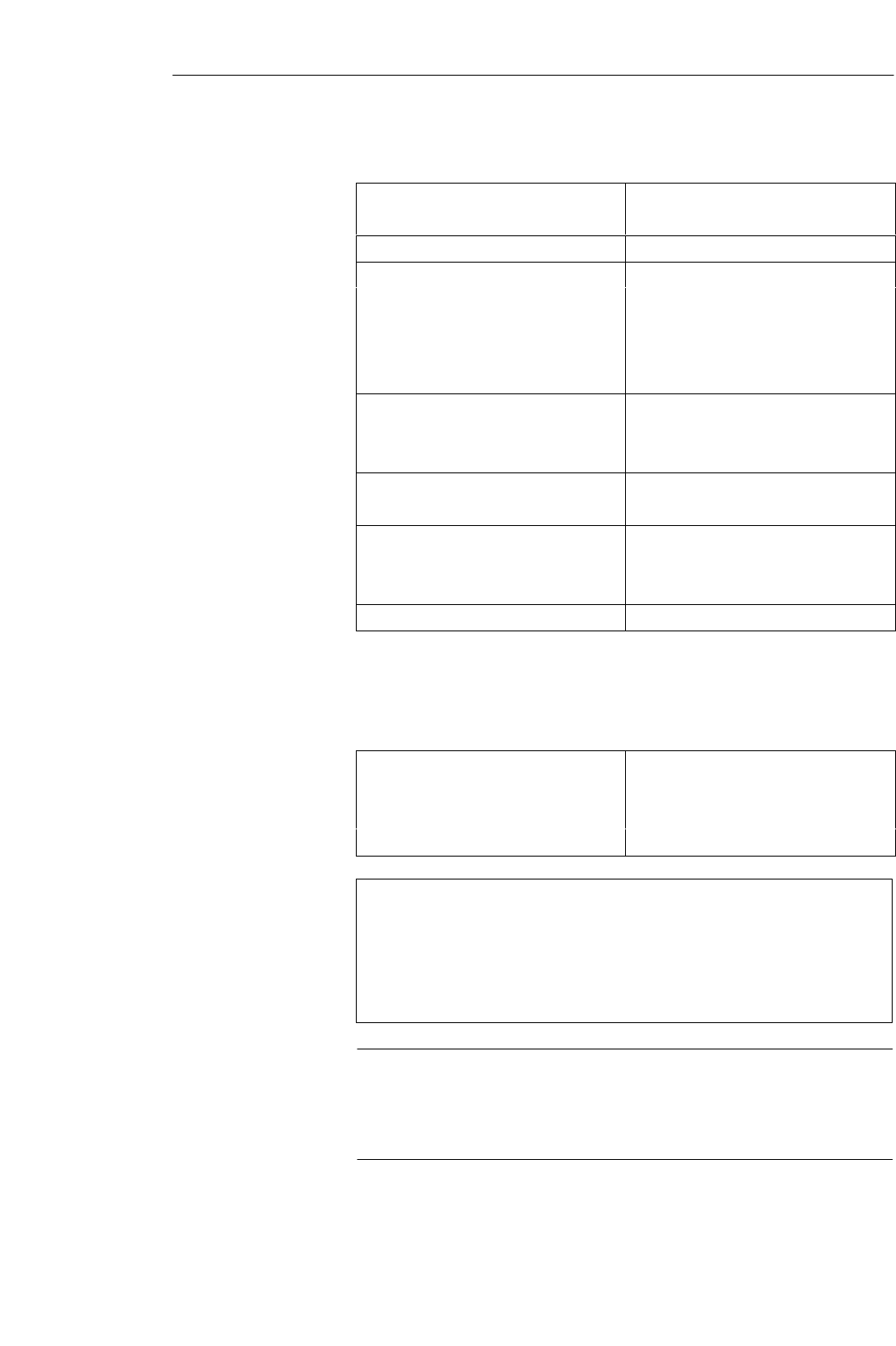
Table 5-8 Ordering data for SLG 41/SLG 41-S
Read/write device up to 25 mm
SLG 41
SLG 41-S (antenna turned 90°)
SLG plug connector and stub lines
6GT2 001-0AA00
6GT2 001-0AA00-ZA23
See chapter 3.10
Table 5-9 Technical data of SLG 41/SLG 41-S
Inductive interface to MDS
Data transmission speed 19200 baud
Read/write distance
SLG to MDS (max.) 30 mm (see field data table)
Transmission frequency
SPower 134 kHz
SData 1.81 MHz
Serial interface to ASM 6-pin SLG plug connector in acc. w.
DIN 43651
Transmission speed 19200 baud, RS 422
Line length, ASM to SLG (max.)
at 24 V DC 360 m
Supply voltage (via serial interface)
Nominal value 24 V DC
Permissible range 20 to 30 V DC
Application area
Ordering data
Technical data
Read/Write Devices
5-13
MOBY I Configuration, Installation and Service Manual
(4) J31069-D0033-U001-A7.1-7618
Table 5-9 Technical data of SLG 41/SLG 41-S
Current consumption
Idle/operation 20 mA / 90 mA
MTBF 2 x 10⁶
Housing
Dimensions in mm (W x H x D) 120 x 40 x 40
Color Anthracite/ergo-gray
Material Polyamide 12
Plug connection DIN 43651
Protection rating IP65
Shock 50 g
Vibration 20 g
Mounting of SLG 4 M5 screws
Turning moment (at room temperature) v 3 Nm
Ambient temperature
During operation –25° to +70° C
During transportation and storage –40° to +85° C
Weight (approx.) 210 g
The exact field data are dependent on the type of MDS used.
Table 5-10 Field data of SLG 41/SLG 41-S
Operating distance (Sa)0 to 15 mm
Limit distance (Sg)30 mm
Median deviation (L) Depends on MDS
Minimum distance from SLG to SLG (D) > 200 mm
Made in Germany
SIEMENS MOBY I SLG 41
THIS DEVICE COMPLIES WITH PART 15 OF THE FCC RULES: OPERATION IS SUBJECT TO
THE FOLLOWING TWO CONDITIONS:
(1) THIS DEVICE MAY NOT CAUSE HARMFUL INTERFERENCE, AND (2) THIS DEVICE MUST
ACCEPT ANY INTERFERENCE THAT MAY CAUSE UNDESIRED OPERATION.
Note
The manufacturer is not responsible for any radio or TV interference caused
by unauthorized modifications to this equipment:
Such modifications could void the user’s authority to operate the equipment.
Field data
FCC information
Read/Write Devices
5-14 MOBY I Configuration, Installation and Service Manual
(4) J31069-D0033-U001-A7.1-7618
SIEMENS
M M
SIEMENS
M
M
Transmission window at operating distance
Length of
transmission
window (L)
SLG 41-S
Transmission win-
dow at operating
distance
Length of trans-
mission window
(L)
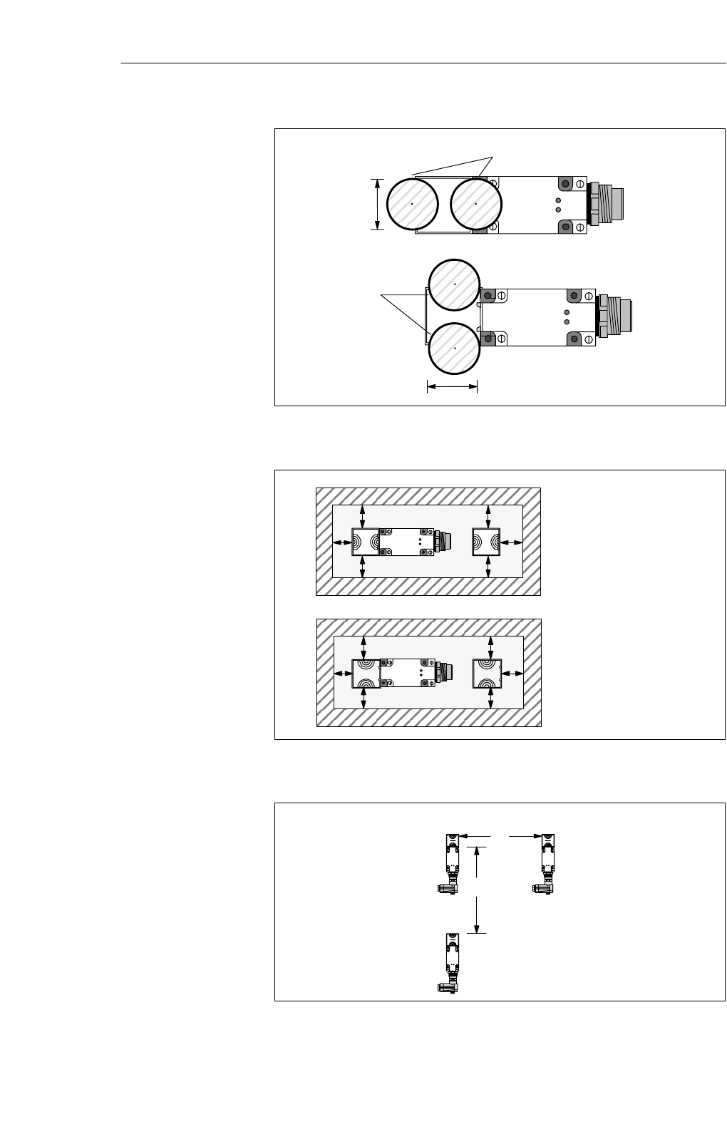
Figure 5-13 Transmission window of SLG 41/SLG 41-S
a
a
aa
a
a
SIEMENS
SIEMENS
a
a
aa
a
a
SIEMENS
SIEMENS
a = 25 mm
Metal-free space
with flush installation
a = 25 mm
Metal-free
space with flush
installation
Figure 5-14 Metal-free space for SLG 41/SLG 41-S
D
D
SLG 41 / SLG 41-S
SLG 41
SLG 41
Figure 5-15 Distance D for SLG 41/SLG 41-S
Transmission
window
Metal-free space
Definition of
distance D
Read/Write Devices
5-15
MOBY I Configuration, Installation and Service Manual
(4) J31069-D0033-U001-A7.1-7618
40
8040
5,3 60
25
28
40
49
40 30
14.5
SIEMENS
40
8040
5.3 60
25
28
4049
40 30
14.5
SIEMENS
SLG 41:
SLG 41-S:
Position of
swivel head
on delivery
Position of
swivel head
on delivery
.3
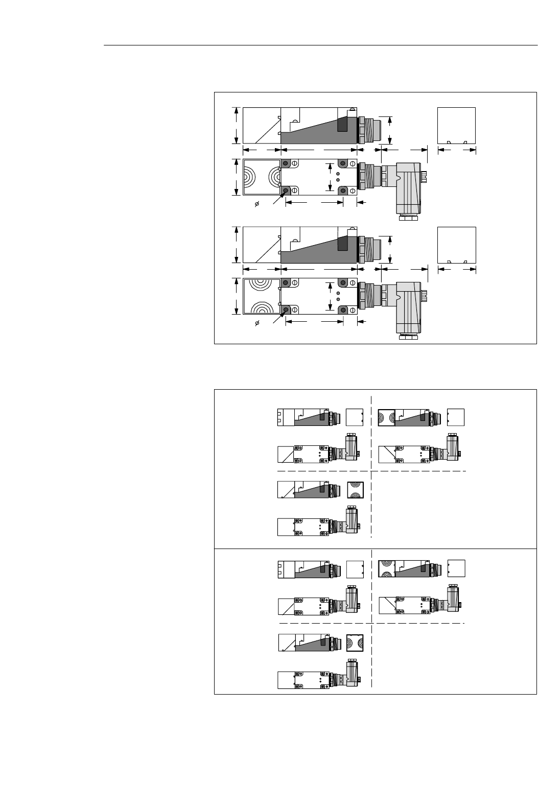
Figure 5-16 Dimensional diagram of SLG 41/SLG 41-S
SIEMENS
SIEMENS
SIEMENS
SIEMENS
SLG 41
SLG 41-S
Figure 5-17 Read head changes of SLG 41/SLG 41-S
Dimensions
(in mm)
Possible read head
changes with the
swivel head
Read/Write Devices
5-16 MOBY I Configuration, Installation and Service Manual
(4) J31069-D0033-U001-A7.1-7618
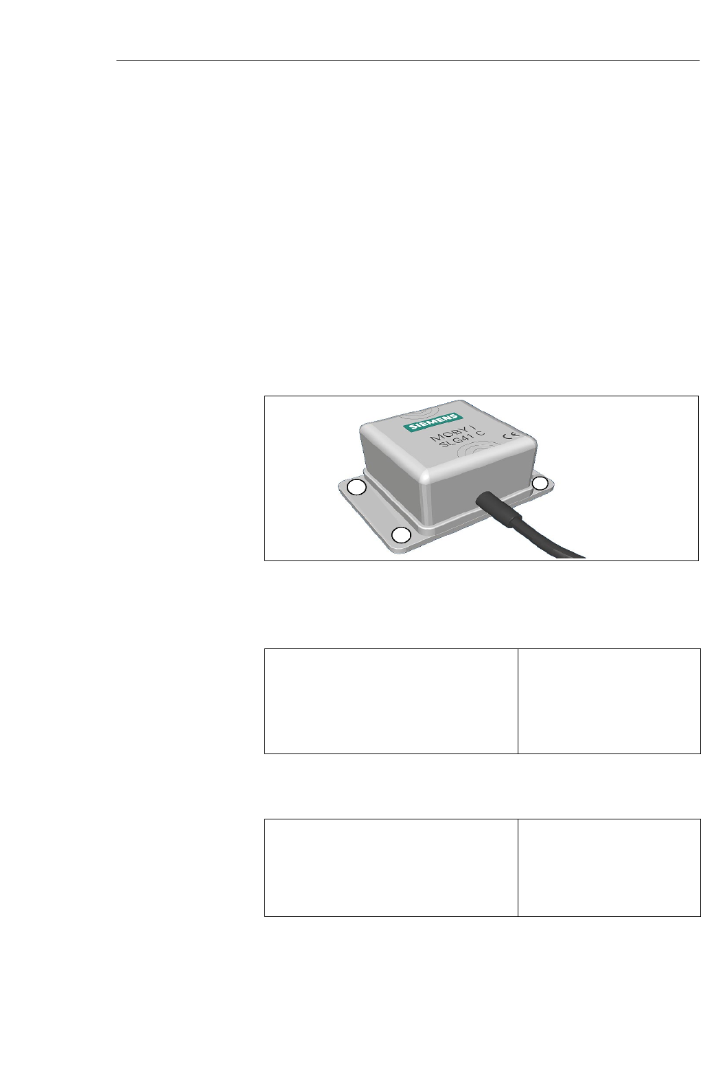
5.5 SLG 41C/SLG 41CC
The SLG 41C is a low-end read/write device. It is small and compact and is
excellent for use in small assembly lines.
The high protection rating and use of high-quality materials ensure that the
SLG 41C can easily handle even most rugged industrial conditions.
It is connected with a 3-m cable which is equipped with core sleeves at the
end. This connection line can be extended with terminals or a user-provided
connection plug. This connection plug of the ASM is used for the connection
to the ASM.
The cable length of the SLG 41CC is 2 m. The end of the cable is equipped
with a twin M-12 plug. This can be used to connect the SLG 41CC directly to
an ASM 450/452/473.
Figure 5-18 SLG 41C/41CC read/write device
Table 5-11 Ordering data of SLG 41C/41CC
Read/write device SLG 41C
SLG 41CC read/write device with
twin M-12 plug
Accessories:
Extension cable (not fabricated)
Connection plug for ASM 450/473
6GT2 001-0AC00
6GT2 001-0AC00-0AX0
6GT2 090-0A...
6GT2 090-0BC00
Table 5-12 Technical data of SLG 41C/41CC
Inductive interface to MDS
Read/write distance, SLG-MDS, max.
Transmission frequency
Power
Data
30 mm (see field data)
134 kHz
1.81MHz
Application area
Ordering data
Technical data
Read/Write Devices

5-17
MOBY I Configuration, Installation and Service Manual
(4) J31069-D0033-U001-A7.1-7618
Table 5-12 Technical data of SLG 41C/41CC
Serial interface to evaluation unit
Data transmission rate
Line length, ASM-SLG max. (for 24V DC)
RS 422
19 200 Baud
360 m
Serial interface to user
SLG 41C
SLG 41CC
3 m connection line;
open end
2 m connection line;
twin M-12 plug for
ASM 450/452/473
Voltage
Nominal value
Permissible range
Current consumption at room temerature
Standby
Operation
24 V DC
20 V to 30 V DC
30 mA
70 mA (typical)
Housing
Dimensions (L x W x H) in mm
Color
Material
Connection
55 x 75 x 30
Gray
Plastic (polyamide 12)
3 m connection line, cable ends
with core sleeves and labels
Protection rating an acc. w. EN 60 529
Shock
Vibration
IP67
50 g
20 g
Mounting of SLG
Tightening moment (at room temperature)
4 M 5 screws
< 2 Nm
Ambient temperature
During operation
During transpostation and storage
–25°C to +70°C
–40°C to +85°C
Weight approx. 210 g
Read/Write Devices
5-18 MOBY I Configuration, Installation and Service Manual
(4) J31069-D0033-U001-A7.1-7618
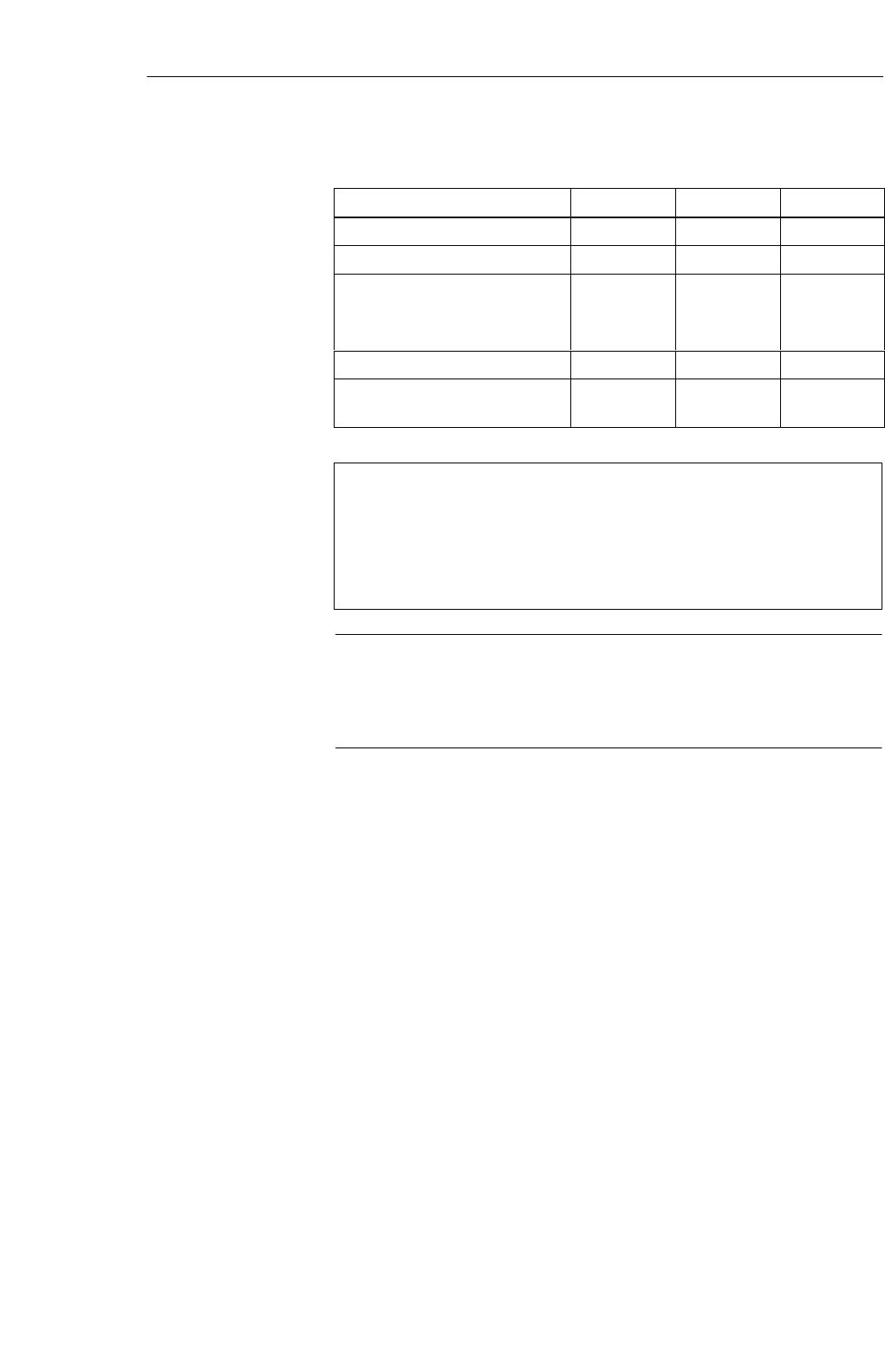
Table 5-13 Field data of SLG 41C/41CC
MDS 401/402 MDS 403 MDS 404/514
Working distance (Sa)0 to 6 4 to 15 0 to 12
Limit distance (Sg) 10 30 25
Transmission window
SL: Vertical
S2L: Horizontal
20
40
65
–
30
60
Width of transmission window (W) 8 25 12
Minimum distance from
SLG to SLG w200 w200 w200
Made in Germany
SIEMENS MOBY I SLG 41C
THIS DEVICE COMPLIES WITH PART 15 OF THE FCC RULES: OPERATION IS SUBJECT TO
THE FOLLOWING TWO CONDITIONS:
(1) THIS DEVICE MAY NOT CAUSE HARMFUL INTERFERENCE, AND (2) THIS DEVICE MUST
ACCEPT ANY INTERFERENCE THAT MAY CAUSE UNDESIRED OPERATION.
Note
The manufacturer is not responsible for any radio or TV interference caused
by unauthorized modifications to this equipment:
Such modifications could void the user’s authority to operate the equipment.
Field data (in mm)
FCC information
Read/Write Devices
5-19
MOBY I Configuration, Installation and Service Manual
(4) J31069-D0033-U001-A7.1-7618
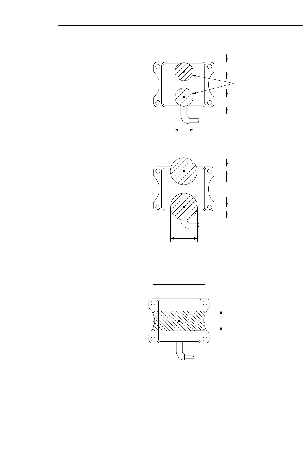
The transmission window
is marked on the housing
Length of the transmission window for (L)
MDS 404/514
Length of the transmission window (L)
for MDS 401/402
12
12
5
5
M
M
M
Transmission window
at working distance
20
30
B = 25
Width of the
transmission window
L = 65
Length of the
transmission window Transmission window
at working distance
The MDS moves along the
“SIEMENS” label on the
housing.
M
SIEMENS
M
Lenght of the transmisison window for
MDS 403
M
Figure 5-19 Transmission window of SLG 41C/41CC
Transmission
window
Read/Write Devices
5-20 MOBY I Configuration, Installation and Service Manual
(4) J31069-D0033-U001-A7.1-7618
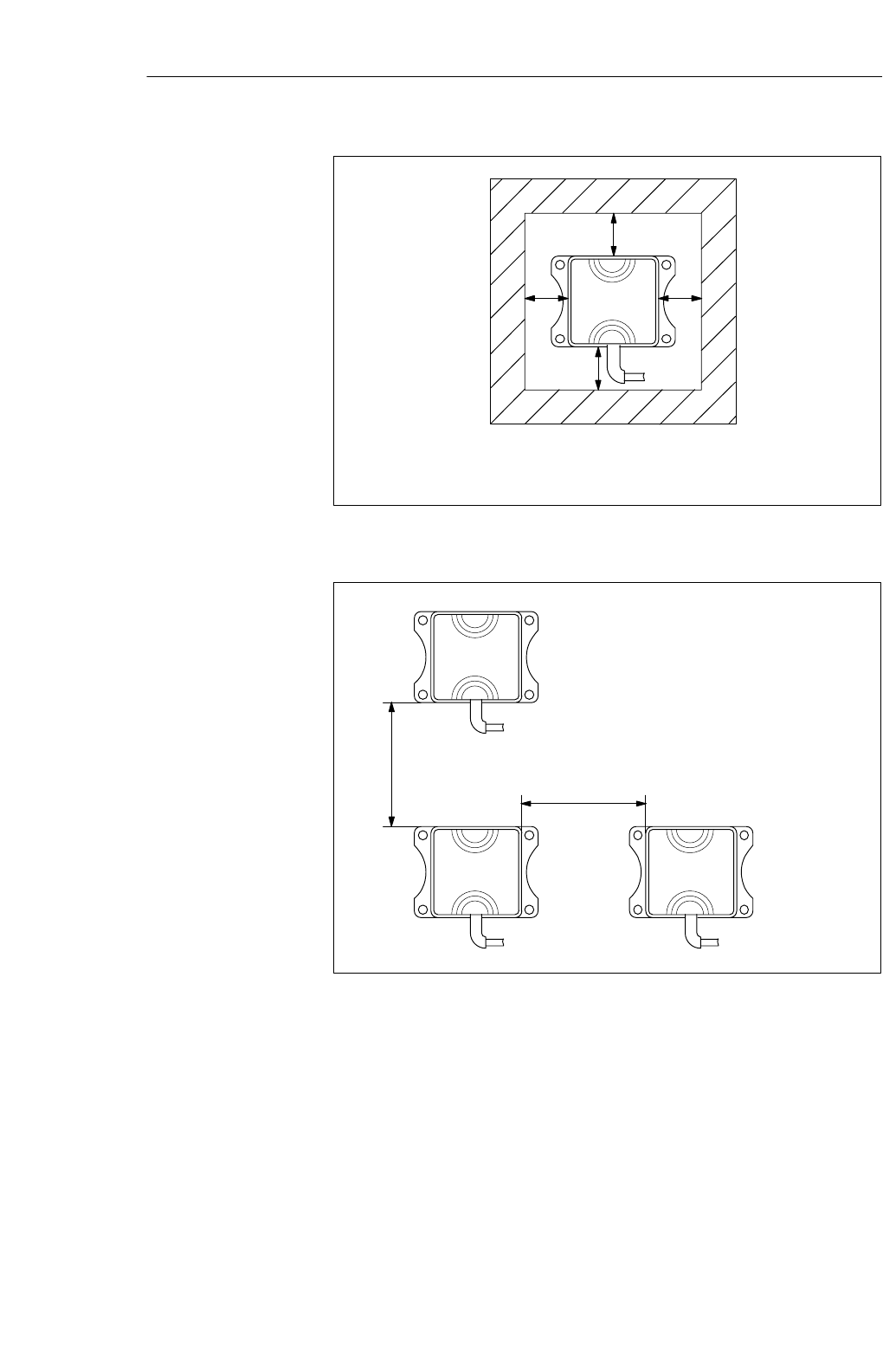
a = 15 mm
Metal-free area with flush installation
SIEMENS
MOBY I
SLG 41C
a
a
a a
Figure 5-20 Metal-free area of SLG 41C/41CC
Minimum distance from SLG to SLG
D = ≥ 200 mm
SIEMENS
MOBY I
SLG 41C
D
D
SIEMENS
MOBY I
SLG 41C
SIEMENS
MOBY I
SLG 41C
Figure 5-21 Distance D: SLG 41C/41CC
Metal-free space
Definition of
distance D
Read/Write Devices
5-21
MOBY I Configuration, Installation and Service Manual
(4) J31069-D0033-U001-A7.1-7618
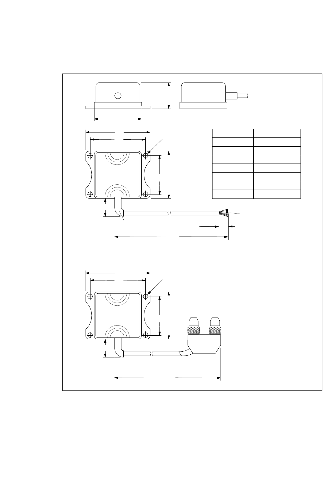
∅5.5
45 55
75
65
w30
Core and sleeves
Flexible cable
anti-kink guard
3 m
0.1 m
55
30
SIEMENS
MOBY I
SLG 41C
∅5.5
45 55
75
65
w30
2 m
SIEMENS
MOBY I
SLG 41CC
Core color Designation
Brown – Receiving
Pink + 24 V
Gray Ground (0V)
Green + Sending
Yellow – Sending
White + Receiving
Black Cable shield
Figure 5-22 Dimensions of SLG 41C/41CC
Dimensions
(in mm)
Read/Write Devices