Siemens MOBYU-STGU portable Write-Read-Station, Identification system User Manual MOBY STG E
Siemens AG portable Write-Read-Station, Identification system MOBY STG E
UserManual.wiki
>
Siemens
>
MOBYU STGU User Manual
user manual
Navigation menu
Upload a User Manual
Namespaces
Wiki Guide
HTML
PDF
Info
Views
User Manual
Discussion / Help
Navigation

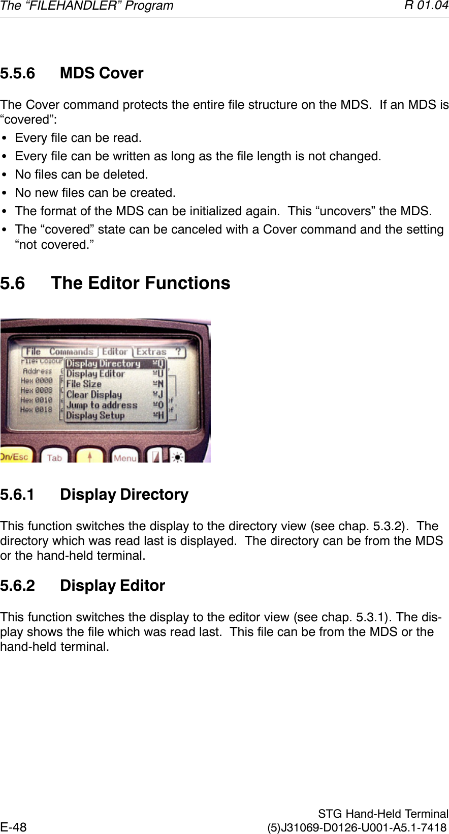
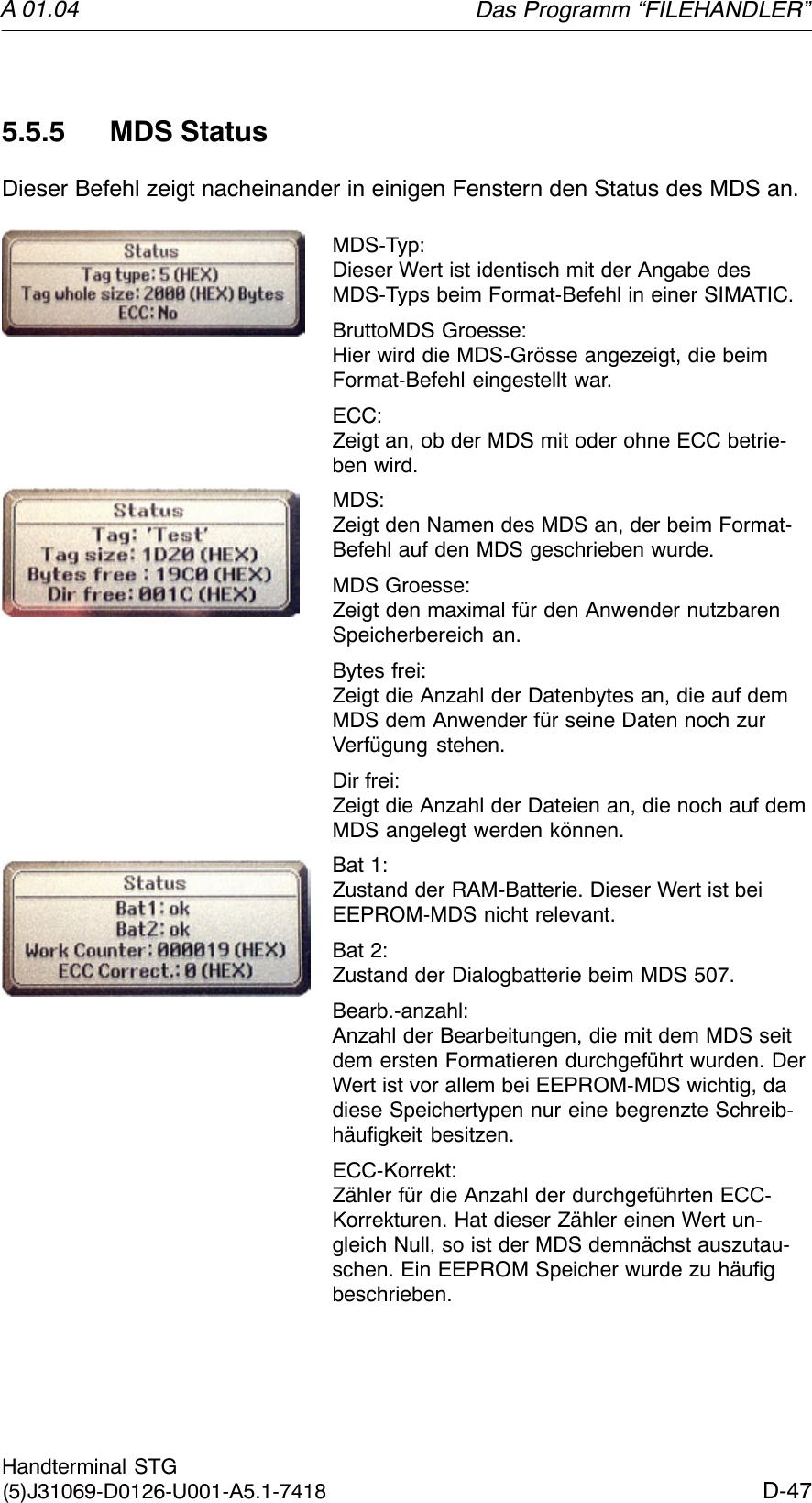
![R 01.04E-24 STG Hand-Held Terminal(5)J31069-D0126-U001-A5.1-74184.2.5 Reading MDS StatusOnly MOBY U: The function reads the status data from the MDS and indicatesit.MDS status informationSMDS number (8-position, hexadecimal format) and MDS memory size (2 or32 kB)SData for calculation of the battery lifespan (total accesses, total search, andchange sleep time)SRemaining battery life time of the MDS in %SSleep time set on MDSNoteFor calculation of the battery lifespan of the MOBY U data medium,it is essential that the STG software have the current calendar weekand the current calendar year. This is the reason the date must beset correctly on the PSION Workabout.The date can be set via the system menu “Time” → “Time and date.”Proceed as shown below.SExit the MOBY U service and test program via “File/Exit.”SSelect “System screen.”SPosition the cursor on the application “IMG.”SClick the “Menu” button.SSelect “CTRL/Set time and date.”SSet “Time” and “Date” and accept with “Enter” button.SReturn to the MOBY U service and test program via “IMG” and“Moby_u[A].”The “MOBY D/E/F/I/U” Programs](https://usermanual.wiki/Siemens/MOBYU-STGU/User-Guide-388584-Page-30.png)
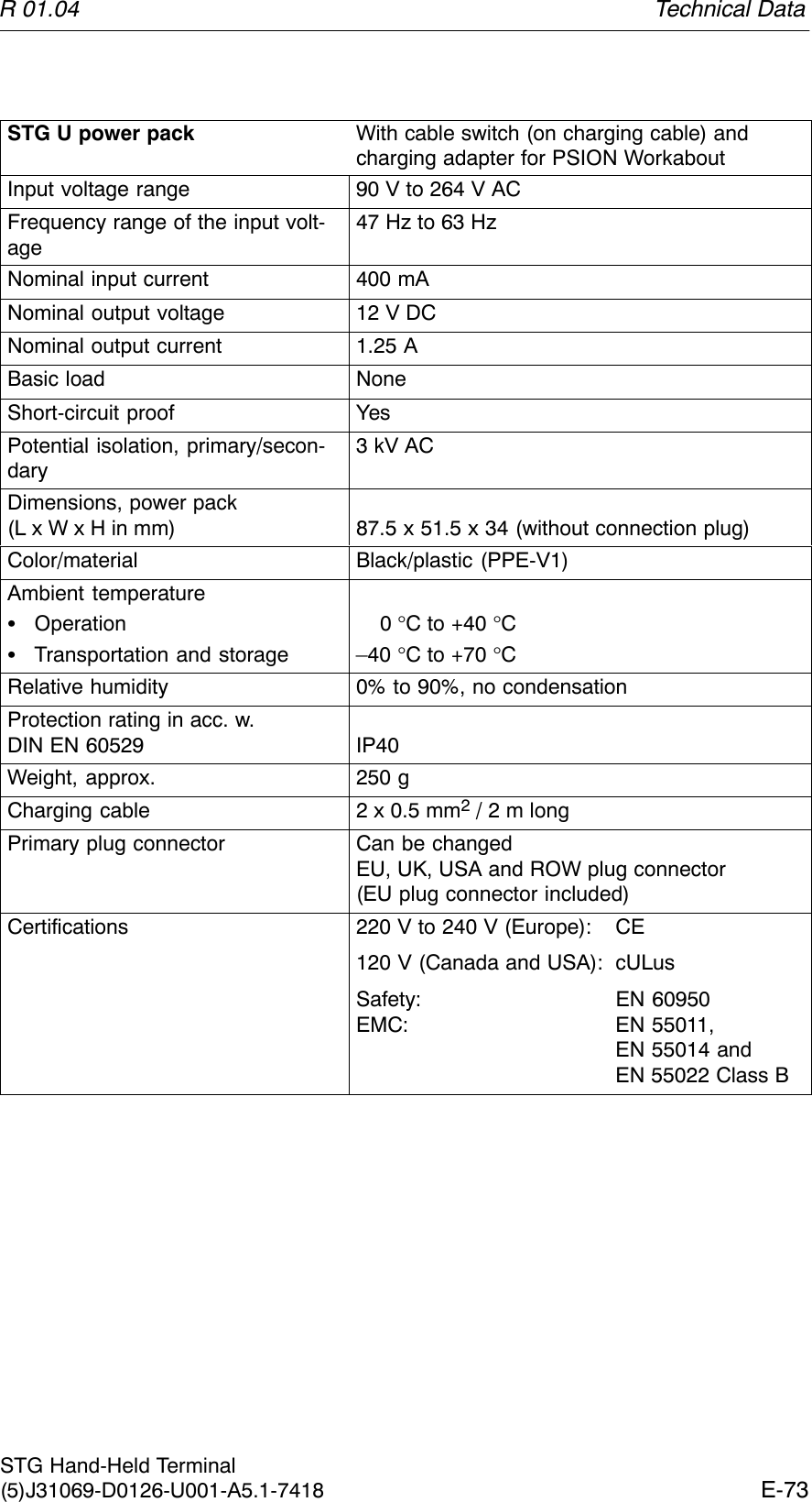
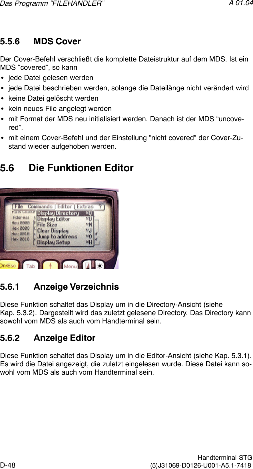
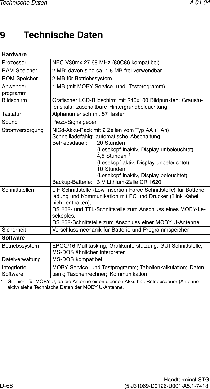
90 x 64 x 35 [mm](MOBY D/E/F/I)282 x 235 x 93 [mm] (MOBY U)Weight Approx. 480 g (MOBY D/E/F/I)Approx. 100 g (MOBY D/E/F/I)Approx. 1450 g (MOBY U) Approx. 1100 g (MOBY U)Temperature Operation: –20 °C to +60 °CStorage: –25 °C to +70 °C (without batteries)Relative humidity 0% to 90%, no condensationProtection rating IP54 (protected against splashed water) 2Shock resistance Max. falling height on concrete: 1 m (MOBY D/E/F/I)0.5 m (MOBY U)EMC EN 55022Electrostatic, RF,EFTIEC 801-2; IEC 801-3; IEC 801-42 With STG U hand-held terminal, only for complete device with PSION WorkaboutTechnical Data](https://usermanual.wiki/Siemens/MOBYU-STGU/User-Guide-388584-Page-75.png)

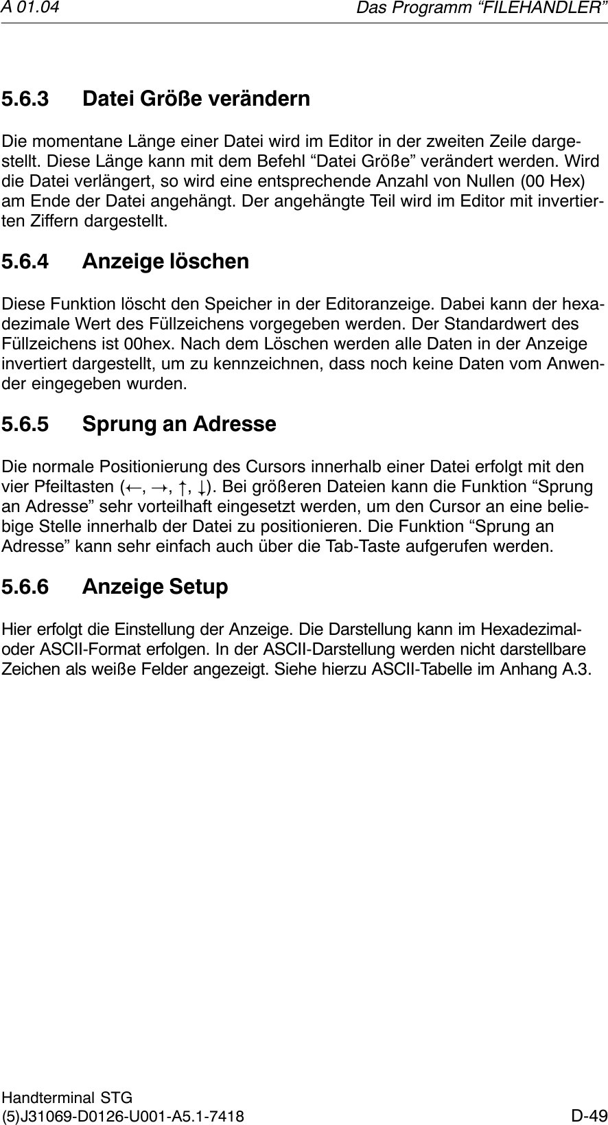
![A 01.04D-24 Handterminal STG(5)J31069-D0126-U001-A5.1-74184.2.5 MDS-Status lesenNur MOBY U: Die Funktion liest die Statusdaten vom MDS aus und zeigt siean.MDS-Statusinformationen:SMDS-Nummer (8 stellige hexadezimale Darstellung) und MDS-Speicher-größe (2 oder 32 kB)SDaten für die Berechnung der Batterielebensdauer (“Summe Zugriffe”,“Summe Suche” und “Aender. Sleep Time”)SRestliche Batterielebensdauer des MDS in %SEingestellte Sleep Time im MDSHinweisFür die Berechnung der Batterielebensdauer der MOBY U-Daten-träger benötigt die STG-Software unbedingt die aktuelle Kalender-woche und das aktuelle Kalenderjahr. Deshalb muss im PSION Workabout das Datum korrekt eingestellt sein.Das Datum können Sie über das Systemmenü “Time” → “Time anddate” einstellen.Gehen Sie hierzu wie folgt vor:SVerlassen Sie das MOBY U Service- und Testprogramm über“Datei/Beenden”SWählen Sie “System screen” ausSPositionieren Sie den Cursor auf die Anwendung “IMG”SBetätigen Sie die Taste “Menu”SWählen Sie “CTRL/Set time and date”SStellen Sie “Time” und “Date” ein und übernehmen mit der “Enter”-TasteSKehren Sie über “IMG” und “Moby_u[A]” in das MOBY U Service-und Testprogramm zurückDie Programme “MOBY D/E/F/I/U”](https://usermanual.wiki/Siemens/MOBYU-STGU/User-Guide-388584-Page-118.png)
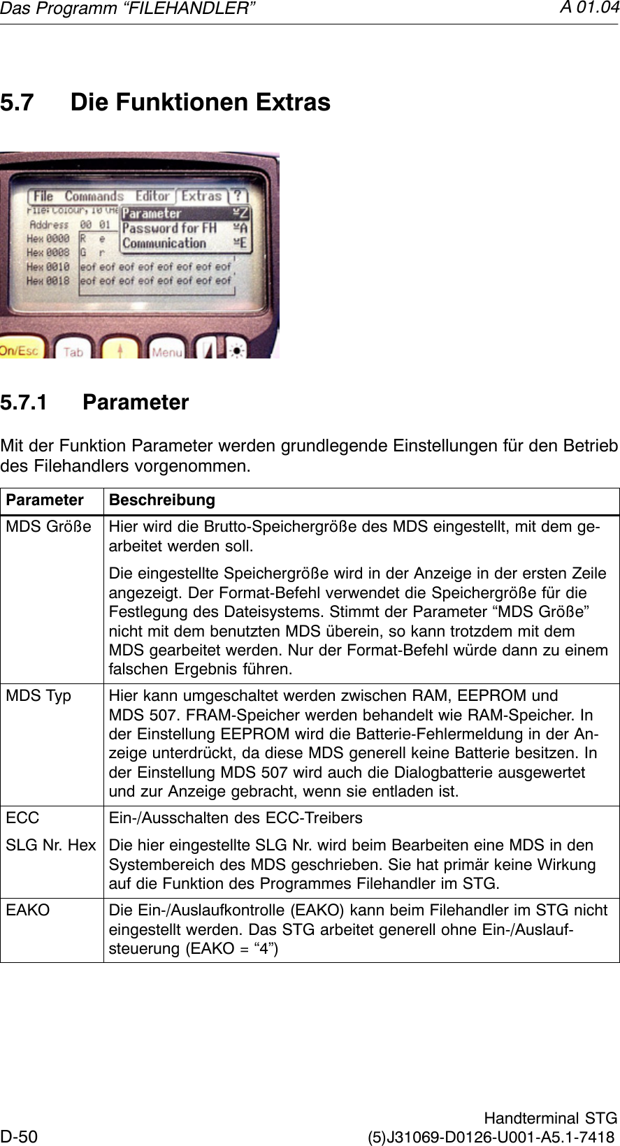
![A 01.04D-69Handterminal STG(5)J31069-D0126-U001-A5.1-7418Technische DatenKomplettgerät (inkl. Akkus)Lesekopf/AntenneAbmessungen 90 x 260 x 35 [mm] (MOBY D/E/F/I)90 x 64 x 35 [mm] (MOBY D/E/F/I)282 x 235 x 93 [mm] (MOBY U)Gewicht ca. 480 g (MOBY D/E/F/I) ca. 100 g (MOBY D/E/F/I)ca. 1450 g (MOBY U) ca. 1100 g (MOBY U)Temperatur Betrieb: –20 °C bis +60 °CLagerung: –25 °C bis +70 °C (ohne Batterie)Relative Feuchtigkeit0 % bis 90 % nicht kondensierendSchutzart IP54 (spritzwassergeschützt) 2Schlagfestigkeit Max. Fallhöhe auf Beton: 1 m (MOBY D/E/F/I)0,5 m (MOBY U)EMV EN 55022Elektrostatik; RF;EFTIEC 801-2; IEC 801-3; IEC 801-42 Bei Handterminal STG U nur für Komplettgerät mit PSION WorkaboutTechnische Daten](https://usermanual.wiki/Siemens/MOBYU-STGU/User-Guide-388584-Page-163.png)