Siemens MOBYU-STGU portable Write-Read-Station, Identification system User Manual MOBY STG E
Siemens AG portable Write-Read-Station, Identification system MOBY STG E
Siemens >
user manual

Table of Contents
General 1
Commissioning the STG 2
Using the STG 3
The “MOBY D/E/F/I/U”
Programs 4
The “FILEHANDLER”
Program 5
Expanded Functions 6
The “MOBY D/E/F/I/U”
Programs with the
PSION Numeric Model 7
Error Messages 8
Technical Data 9
Appendix A
Published in January 2004
(5)J31069-D0126-U001-A5.1-7418
User’s Guide
MOBY
STG Hand-Held Terminal

Safety Guidelines
This manual contains notices which you should observe to ensure your own per-
sonal safety, as well as to protect the product and connected equipment. These
notices are highlighted in the manual by a warning triangle and are marked as
follows according to the level of danger:
Note
draws your attention to particularly important information on the product,
handling the product, or to a particular part of the documentation.
Qualified Personnel
The device/system may only be set up and operated in conjunction with this
manual.
Only qualified personnel should be allowed to install and work on this equip-
ment. Qualified persons are defined as persons who are authorized to commis-
sion, to ground, and to tag circuits, equipment, and systems in accordance with
established safety practices and standards.
Correct Usage
Note the following:
!Warning
This device and its components may only be used for the applications de-
scribed in the catalog or the technical description, and only in connection
with devices or components from other manufacturers which have been
approved or recommended by Siemens.
This product can only function correctly and safely if it is transported,
stored, set up, and installed correctly, and operated and maintained as
recommended.
Trademarks
MOBYR is a trademark of SIEMENS AG.
Some of the other designations used in these documents are also registered
trademarks; the owner’s rights may be violated if they are used be third parties
for their own purposes.
We have checked the contents of this manual for
agreement with the hardware and software descri-
bed. Since deviations cannot be precluded entirely,
we cannot guarantee full agreement. However, the
data in this manual are reviewed regularly and any
necessary corrections included in subsequent edi-
tions. Suggestions for improvement are welcomed.
Disclaimer of LiabilityCopyright ESiemens AG 1999 All rights reserved
The reproduction, transmission or use of this
document or its contents is not permitted without
express written authority. Offenders will be liable for
damages. All rights, including rights created by patent
grant or registration of a utility model or design, are
reserved.
Siemens AG
Automation and Drives Group
Division Special Products,
Projects Automotive Industry, Training
PO Box 4848, D-90327 Nuremberg E Siemens AG 1999, 2000, 2002, 2003, 2004
Technical data subject to change.
Siemens Aktiengesellschaft Order No. (5)J31069-D0126-U001-A5.1-7418

R 01.04
E-I
STG Hand-Held Terminal
(5)J31069-D0126-U001-A5.1-7418
Table of Contents
1 General E-1. . . . . . . . . . . . . . . . . . . . . . . . . . . . . . . . . . . . . . . . . . . . . . . . . . . . .
1.1 Application Areas E-1. . . . . . . . . . . . . . . . . . . . . . . . . . . . . . . . . . . . . .
1.2 Product Description E-1. . . . . . . . . . . . . . . . . . . . . . . . . . . . . . . . . . . .
1.3 FCC Information for the USA E-3. . . . . . . . . . . . . . . . . . . . . . . . . . . .
2 Commissioning the STG E-4. . . . . . . . . . . . . . . . . . . . . . . . . . . . . . . . . . . . .
2.1 Included Components E-4. . . . . . . . . . . . . . . . . . . . . . . . . . . . . . . . . .
2.2 Assembly E-5. . . . . . . . . . . . . . . . . . . . . . . . . . . . . . . . . . . . . . . . . . . . .
2.3 Turning on the Device and Setting the Operating Mode E-6. . . . .
2.4 MOBY Applications E-7. . . . . . . . . . . . . . . . . . . . . . . . . . . . . . . . . . . .
2.5 User Interface E-7. . . . . . . . . . . . . . . . . . . . . . . . . . . . . . . . . . . . . . . . .
3 Using the STG E-8. . . . . . . . . . . . . . . . . . . . . . . . . . . . . . . . . . . . . . . . . . . . . .
3.1 Keyboard E-8. . . . . . . . . . . . . . . . . . . . . . . . . . . . . . . . . . . . . . . . . . . . .
3.2 Antenna on the Read Head and Antenna Field E-9. . . . . . . . . . . .
3.2.1 MOBY D/E/F/I E-9. . . . . . . . . . . . . . . . . . . . . . . . . . . . . . . . . . . . . . . . .
3.2.2 MOBY U E-11. . . . . . . . . . . . . . . . . . . . . . . . . . . . . . . . . . . . . . . . . . . . .
3.3 Using the MOBY U Antenna E-12. . . . . . . . . . . . . . . . . . . . . . . . . . . .
3.4 Charging Function E-13. . . . . . . . . . . . . . . . . . . . . . . . . . . . . . . . . . . . .
3.5 Changing the Battery Pack of the MOBY U Antenna E-16. . . . . . .
4 The “MOBY D/E/F/I/U” Programs E-17. . . . . . . . . . . . . . . . . . . . . . . . . . . . .
4.1 Data Editor E-19. . . . . . . . . . . . . . . . . . . . . . . . . . . . . . . . . . . . . . . . . . .
4.2 MDS Functions E-21. . . . . . . . . . . . . . . . . . . . . . . . . . . . . . . . . . . . . . .
4.2.1 General Information on Read and Write-Accessing an MDS E-21.
4.2.2 Reading the MDS E-22. . . . . . . . . . . . . . . . . . . . . . . . . . . . . . . . . . . . .
4.2.3 Writing the MDS E-23. . . . . . . . . . . . . . . . . . . . . . . . . . . . . . . . . . . . . . .
4.2.4 Erasing/Initializing the MDS E-23. . . . . . . . . . . . . . . . . . . . . . . . . . . . .
4.2.5 Reading MDS Status E-24. . . . . . . . . . . . . . . . . . . . . . . . . . . . . . . . . .
4.2.6 Reading the ID Number E-25. . . . . . . . . . . . . . . . . . . . . . . . . . . . . . . .
4.2.7 Reading OTP Memory E-25. . . . . . . . . . . . . . . . . . . . . . . . . . . . . . . . .
4.2.8 Writing OTP memory E-25. . . . . . . . . . . . . . . . . . . . . . . . . . . . . . . . . .
4.2.9 Reading Raw Data E-26. . . . . . . . . . . . . . . . . . . . . . . . . . . . . . . . . . . .
4.3 File Functions E-27. . . . . . . . . . . . . . . . . . . . . . . . . . . . . . . . . . . . . . . . .
4.3.1 Loading a File E-27. . . . . . . . . . . . . . . . . . . . . . . . . . . . . . . . . . . . . . . . .
4.3.2 Saving E-27. . . . . . . . . . . . . . . . . . . . . . . . . . . . . . . . . . . . . . . . . . . . . . .
Table of Contents

R 01.04
E-II STG Hand-Held Terminal
(5)J31069-D0126-U001-A5.1-7418
4.3.3 Exiting E-27. . . . . . . . . . . . . . . . . . . . . . . . . . . . . . . . . . . . . . . . . . . . . . .
4.4 The Editor Functions E-28. . . . . . . . . . . . . . . . . . . . . . . . . . . . . . . . . . .
4.4.1 Jump to Address E-28. . . . . . . . . . . . . . . . . . . . . . . . . . . . . . . . . . . . . .
4.4.2 Display E-28. . . . . . . . . . . . . . . . . . . . . . . . . . . . . . . . . . . . . . . . . . . . . . .
4.4.3 Clear Display E-29. . . . . . . . . . . . . . . . . . . . . . . . . . . . . . . . . . . . . . . . .
4.4.4 Edit Date E-29. . . . . . . . . . . . . . . . . . . . . . . . . . . . . . . . . . . . . . . . . . . . .
4.5 The Extras Functions E-30. . . . . . . . . . . . . . . . . . . . . . . . . . . . . . . . . .
4.5.1 Communication E-30. . . . . . . . . . . . . . . . . . . . . . . . . . . . . . . . . . . . . . .
4.5.2 Password E-31. . . . . . . . . . . . . . . . . . . . . . . . . . . . . . . . . . . . . . . . . . . .
4.5.3 Antenna E-31. . . . . . . . . . . . . . . . . . . . . . . . . . . . . . . . . . . . . . . . . . . . . .
4.5.4 Address Setup E-32. . . . . . . . . . . . . . . . . . . . . . . . . . . . . . . . . . . . . . . .
4.5.5 MOBY I Setup E-33. . . . . . . . . . . . . . . . . . . . . . . . . . . . . . . . . . . . . . . .
4.5.6 MOBY E Setup E-33. . . . . . . . . . . . . . . . . . . . . . . . . . . . . . . . . . . . . . . .
4.5.7 MOBY U Setup E-34. . . . . . . . . . . . . . . . . . . . . . . . . . . . . . . . . . . . . . . .
4.5.8 SLG Status E-34. . . . . . . . . . . . . . . . . . . . . . . . . . . . . . . . . . . . . . . . . . .
4.6 The “?” Functions E-35. . . . . . . . . . . . . . . . . . . . . . . . . . . . . . . . . . . . .
4.6.1 Language E-35. . . . . . . . . . . . . . . . . . . . . . . . . . . . . . . . . . . . . . . . . . . .
4.6.2 About E-35. . . . . . . . . . . . . . . . . . . . . . . . . . . . . . . . . . . . . . . . . . . . . . . .
4.6.3 Version E-35. . . . . . . . . . . . . . . . . . . . . . . . . . . . . . . . . . . . . . . . . . . . . . .
5 The “FILEHANDLER” Program E-36. . . . . . . . . . . . . . . . . . . . . . . . . . . . . . .
5.1 General Information on the Filehandler E-36. . . . . . . . . . . . . . . . . . .
5.2 The Filehandler Commands E-37. . . . . . . . . . . . . . . . . . . . . . . . . . . .
5.3 View of the Editor and Directory E-39. . . . . . . . . . . . . . . . . . . . . . . . .
5.3.1 The Data Editor of the Filehandler E-39. . . . . . . . . . . . . . . . . . . . . . .
5.3.2 View of the Directory E-40. . . . . . . . . . . . . . . . . . . . . . . . . . . . . . . . . . .
5.4 The File Functions E-41. . . . . . . . . . . . . . . . . . . . . . . . . . . . . . . . . . . . .
5.4.1 Read File from MDS (Read File from Tag) E-41. . . . . . . . . . . . . . . .
5.4.2 Read File from STG RAM E-42. . . . . . . . . . . . . . . . . . . . . . . . . . . . . .
5.4.3 Write File to MDS (Write File to Tag) E-42. . . . . . . . . . . . . . . . . . . . .
5.4.4 Write File to STG RAM E-43. . . . . . . . . . . . . . . . . . . . . . . . . . . . . . . . .
5.4.5 Read Directory from MDS (Read Dir from Tag) E-43. . . . . . . . . . . .
5.4.6 Read Directory from STG RAM (Read Dir from STG RAM) E-43.
5.4.7 Example: Copy Files E-44. . . . . . . . . . . . . . . . . . . . . . . . . . . . . . . . . . .
5.5 The Commands Menu E-45. . . . . . . . . . . . . . . . . . . . . . . . . . . . . . . . .
5.5.1 New File (Create File) E-45. . . . . . . . . . . . . . . . . . . . . . . . . . . . . . . . . .
5.5.2 Delete File E-45. . . . . . . . . . . . . . . . . . . . . . . . . . . . . . . . . . . . . . . . . . . .
5.5.3 Format MDS (Tag Format) E-45. . . . . . . . . . . . . . . . . . . . . . . . . . . . . .
5.5.4 Attribute File (File Attribute) E-46. . . . . . . . . . . . . . . . . . . . . . . . . . . . .
5.5.5 MDS Status (Tag Status) E-47. . . . . . . . . . . . . . . . . . . . . . . . . . . . . . .
Table of Contents

R 01.04
E-III
STG Hand-Held Terminal
(5)J31069-D0126-U001-A5.1-7418
5.5.6 MDS Cover E-48. . . . . . . . . . . . . . . . . . . . . . . . . . . . . . . . . . . . . . . . . . .
5.6 The Editor Functions E-48. . . . . . . . . . . . . . . . . . . . . . . . . . . . . . . . . . .
5.6.1 Display Directory E-48. . . . . . . . . . . . . . . . . . . . . . . . . . . . . . . . . . . . . .
5.6.2 Display Editor E-48. . . . . . . . . . . . . . . . . . . . . . . . . . . . . . . . . . . . . . . . .
5.6.3 Change File Size (File Size) E-49. . . . . . . . . . . . . . . . . . . . . . . . . . . .
5.6.4 Delete Display (Clear Display) E-49. . . . . . . . . . . . . . . . . . . . . . . . . .
5.6.5 Jump to Address E-49. . . . . . . . . . . . . . . . . . . . . . . . . . . . . . . . . . . . . .
5.6.6 Display Setup E-49. . . . . . . . . . . . . . . . . . . . . . . . . . . . . . . . . . . . . . . . .
5.7 The Extras Functions E-50. . . . . . . . . . . . . . . . . . . . . . . . . . . . . . . . . .
5.7.1 Parameter E-50. . . . . . . . . . . . . . . . . . . . . . . . . . . . . . . . . . . . . . . . . . . .
5.7.2 Password for Filehandler (Password for FH) E-51. . . . . . . . . . . . . .
5.7.3 Communication E-51. . . . . . . . . . . . . . . . . . . . . . . . . . . . . . . . . . . . . . .
5.8 The “?” Functions E-51. . . . . . . . . . . . . . . . . . . . . . . . . . . . . . . . . . . . .
6 Expanded Functions E-52. . . . . . . . . . . . . . . . . . . . . . . . . . . . . . . . . . . . . . . .
6.1 Storing the MDS Data on the Hand-Held Terminal E-52. . . . . . . . .
6.2 Copying MOBY Data from and to the Hand-Held Terminal E-53. .
6.2.1 What Is Needed in Addition? E-53. . . . . . . . . . . . . . . . . . . . . . . . . . . .
6.2.2 Using the PSION File Manager E-53. . . . . . . . . . . . . . . . . . . . . . . . . .
6.2.3 Organization of the READ.HEX File E-56. . . . . . . . . . . . . . . . . . . . . .
6.2.4 Organization of the READ.HX1 File E-56. . . . . . . . . . . . . . . . . . . . . .
6.3 Functions with the PSION Operating System E-56. . . . . . . . . . . . . .
6.4 Parallel Execution of Several Applications E-57. . . . . . . . . . . . . . . .
6.5 Automatic Power Saver Function E-58. . . . . . . . . . . . . . . . . . . . . . . .
6.6 Connecting SIM Devices (MOBY E/I/V) E-58. . . . . . . . . . . . . . . . . . .
6.7 System RESET E-59. . . . . . . . . . . . . . . . . . . . . . . . . . . . . . . . . . . . . . .
7 The “MOBY D/E/F/I/U” Programs with the PSION Numeric Model E-60
8 Error Messages E-61. . . . . . . . . . . . . . . . . . . . . . . . . . . . . . . . . . . . . . . . . . . . .
8.1 Error Messages with the “MOBY D/E/F/I/U” Programs E-62. . . . . .
8.2 Error Messages with the “FILEHANDLER” Program E-66. . . . . . . .
9 Technical Data E-68. . . . . . . . . . . . . . . . . . . . . . . . . . . . . . . . . . . . . . . . . . . . . .
A Appendix E-74. . . . . . . . . . . . . . . . . . . . . . . . . . . . . . . . . . . . . . . . . . . . . . . . . . .
A.1 Ordering Components for Expanded Functions E-74. . . . . . . . . . . .
A.2 Developing User Applications E-75. . . . . . . . . . . . . . . . . . . . . . . . . . .
A.3 ASCII Table E-80. . . . . . . . . . . . . . . . . . . . . . . . . . . . . . . . . . . . . . . . . . .
Table of Contents

R 01.04
E-IV STG Hand-Held Terminal
(5)J31069-D0126-U001-A5.1-7418
Table of Contents

R 01.04
E-1
STG Hand-Held Terminal
(5)J31069-D0126-U001-A5.1-7418
1 General
The STG (service and test device) is a powerful addition to the MOBY D,
MOBY E, MOBY F, MOBY I or MOBY U identification systems. It is a mobile
hand-held terminal based on the PSION Workabout mx and is designed for ap-
plications in the areas of logistics, distribution and service. In addition, it is an
indispensable aid when commissioning and testing.
1.1 Application Areas
The MOBY hand-held terminal can be used with MOBY D, MOBY E, MOBY F,
MOBY I and MOBY U. The included service and test program makes it easy to
read and write all data memories of MOBY D, MOBY E, MOBY F, MOBY I or
MOBY U.
In addition, it is very simple for customers to program their own applications on
the hand-held terminal. A C library is available from Siemens for programming
the hand-held terminal read heads. Implementation of applications in the areas
of warehousing, logistics and commissioning is easy.
Very sturdy in design and protected against splashed water, the hand-held ter-
minal can also be used in rugged environments. Its display is easy to read,
and in dark areas, display illumination can be turned on.
1.2 Product Description
The MOBY hand-held terminal consists of a basic device and a read head from
MOBY D, MOBY E, MOBY F or MOBY I or an antenna of MOBY U. The basic de-
vice is a PSION Workabout mx. This device is the worldwide standard for hand-
held terminals. In addition, the terminal includes a memory card with the MOBY
service and test program including a user’s manual. The memory card is inserted
in the basic device. The service and test program starts automatically when the
hand-held terminal is turned on. All data memories of MOBY D, MOBY E,
MOBY F, MOBY I or MOBY U can be processed with the hand-held terminal.
General

R 01.04
E-2 STG Hand-Held Terminal
(5)J31069-D0126-U001-A5.1-7418
The following functions can be executed.
SRead data from the MDS
SWrite data to the MDS
SDelete the entire data memory (write with a filler value)
SRead and display the ID number of the MDS (MOBY D/E/F/U)
SRead MDS status (MOBY U)
SRead data from OTP memory (MOBY U)
SWrite data to OTP memory (MOBY U)
SRepresent and edit the data in hexadecimal and ASCII format
SEnable/disable password protection for all write-access functions and for
exiting the MOBY program
SMenu prompting in various languages (currently German and English)
SStore read MOBY data in files. Approximately 1.8 MB are available for this
on the hand-held terminal.
Additional functions with the MOBY I filehandler
SFormat the MDS
SCreate files on the MDS
SWrite files to the MDS
SRead files from the MDS
SRead and display the directory
SDelete files from the MDS
The read/write head of MOBY D/E/F/I is screwed to the PSION basic device.
The head is equipped with a serial TTL interface for communication with the
basic device. The read head is powered by the basic device.
The antenna of MOBY U and the PSION basic device are connected with a
slide catch. Communication takes place via the RS 232 interface. The power
supply of the antenna is provided by an integrated battery pack.
The read/write head or the antenna and the STG program can also be ordered
separately so that customers can continue to use an already existing PSION
Workabout or order a Workabout with a different interface and keyboard config-
uration directly from PSION.
General

R 01.04
E-3
STG Hand-Held Terminal
(5)J31069-D0126-U001-A5.1-7418
The appropriate charging device (including 230 V plug-in power pack) for re-
charging the batteries must be ordered separately.
SMOBY D/E/F/I
The charging device (order number 6GT2 303-1DA00) is designed for
mounting on walls or vehicles. When mounted on a vehicle, a special
PSION cable is required for the charging function. See appendix A.1.
SMOBY U
The batteries of the hand-held terminal (in PSION Workabout and the an-
tenna) are charged with the power pack (order number 6GT2 503-1DA00).
See chap. 3.4.
For applications, a C library is available to the user with the functions of the
MOBY read head. Users can develop their own programs (cf. appendix A.2)
with the optional C development environment.
1.3 FCC Information for the USA
SPSION basic device – See PSION user’s manual.
SMOBY E/I/U read head/antenna
Made in Germany
SIEMENS MOBY STG
FCC ID: KR5MIS
KR5MIS-I
NXWMOBYU-STGU
THIS DEVICE COMPLIES WITH PART 15 OF THE
FCC RULES: OPERATION IS SUBJECT TO THE
FOLLOWING TWO CONDITIONS:
(1) THIS DEVICE MAY NOT CAUSE HARMFUL
INTERFERENCE, AND (2) THIS DEVICE MUST
ACCEPT ANY INTERFERENCE THAT MAY CAUSE
UNDESIRED OPERATION.
(for MOBY E)
(for MOBY I)
(for MOBY U)
Note
The manufacturer is not responsible for any radio or TV interference
caused by unauthorized modifications to this equipment:
Such modifications could void the user’s authority to operate the
equipment.
General

R 01.04
E-4 STG Hand-Held Terminal
(5)J31069-D0126-U001-A5.1-7418
2 Commissioning the STG
2.1 Included Components
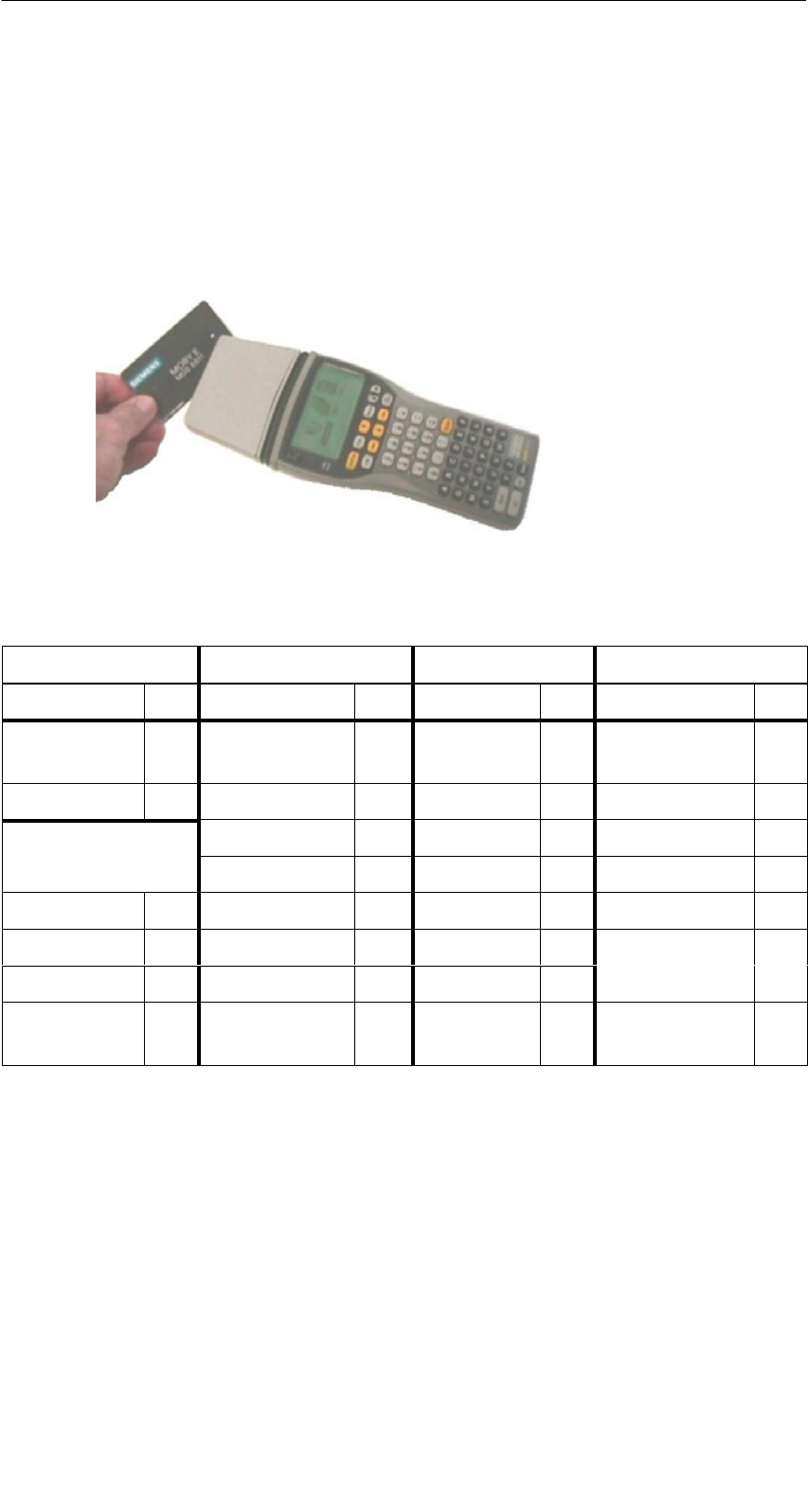
The STG consists of several components which are listed individually on the
delivery slip.
Ordered
Components
Order Number Pack List Pack Number
MOBY D
h d h ld
6GT2 603-0AA00 PSION Workabout mx A5E00016735
hand-held
terminal STG
MOBY D read head 6GT2 603-1AA00
t
erm
i
n
al STG
Memory card incl.
STG software and
user’s manual
6GT2 303-1CA00
NiCd battery 6GT2 094-0AB00
MOBY E
h d h ld
6GT2 303-0AA00 PSION Workabout mx A5E00016735
hand-held
terminal STG
MOBY E read head 6GT2 303-1AA00
t
erm
i
n
al STG
Memory card incl.
STG software and
user’s manual
6GT2 303-1CA00
NiCd battery 6GT2 094-0AB00
MOBY F
h d h ld
6GT2 403-0BA00 PSION Workabout mx A5E00016735
hand-held
terminal STG
MOBY F read head 6GT2 403-1BA00
t
erm
i
n
al STG
Memory card incl.
STG software and
user’s manual
6GT2 303-1CA00
NiCd battery 6GT2 094-0AB00
MOBY I
h d h ld
6GT2 003-0CA00 PSION Workabout mx A5E00016735
hand-held
terminal STG
MOBY I read head 6GT2 003-1CA00
t
erm
i
n
al STG
Memory card incl.
STG software and
user’s manual
6GT2 303-1CA00
NiCd battery 6GT2 094-0AB00
Commissioning the STG

R 01.04
E-5
STG Hand-Held Terminal
(5)J31069-D0126-U001-A5.1-7418
Ordered
Components
Pack NumberPack ListOrder Number
MOBY U
h d h ld
6GT2 503-0AA00 PSION Workabout mx A5E00016735
hand-held
terminal STG
MOBY U antenna 6GT2 503-1AA00
t
erm
i
n
al STG
Memory card incl.
STG software and
user’s manual
6GT2 303-1CA00
NiCd battery 6GT2 094-0AB00
2.2 Assembly
Perform the following steps in the order shown below.
SInstall button cell. Button cell is located in a recess in the packaging of the
PSION Workabout.
SInsert batteries. The battery catch must point to the left.
SInsert the flash program memory with the STG application in the upper
slot (A).
SInstall read head, and screw down (MOBY D/E/F/I).
SJoin antenna and PSION Workabout (MOBY U).
– Screw the PSION Workabout to the metal frame with 4 screws.
– Plug the submin D plug of the MOBY U antenna into the RS 232 interface
of the PSION Workabout and screw down.
– Slide the PSION Workabout on the guide rail of the upper housing shell of
the antenna until the lock snaps in.
Assembly is complete.
Commissioning the STG
R 01.04
E-6 STG Hand-Held Terminal
(5)J31069-D0126-U001-A5.1-7418
2.3 Turning on the Device and Setting the
Operating Mode
Note
Before you turn on the device, insert the hand-held terminal in the
charging device (MOBY D/E/F/I) or connect to the power pack
(6GT2 503-1DA00) (MOBY U) and allow it to charge for at least
14 hours.
After charging, the hand-held terminal is ready for use.
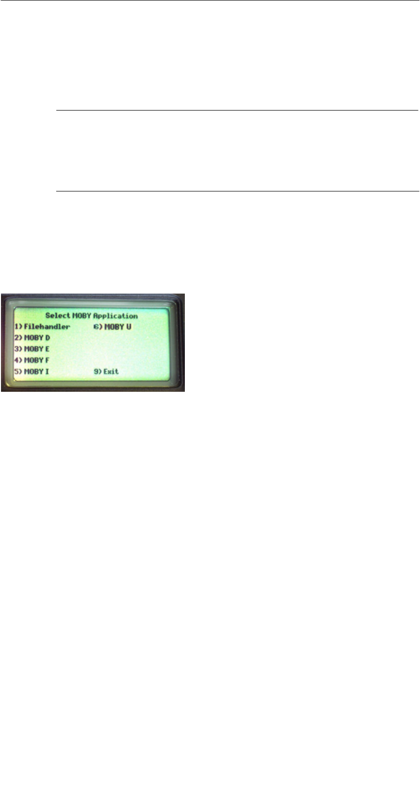
After the terminal is turned on, initial startup takes several seconds. The MOBY
application then starts automatically, and a selection menu appears with the
MOBY applications. Select the MOBY application for the RF read/write head or
the antenna which you want to use.
1) MOBY filehandler for MOBY I
The MDS data are accessed by file
names. See chapter 5.
2)-6)Normal MOBY service and test pro-
gram for MOBY D/E/F/I/U. The MDS
data are accessed by physical addres-
ses. See chapter 4.
9) The operating system of the hand-held
terminal is accessed with “Exit.”
V) Version indication in MOBY application
menu (not shown in selection menu)
The device goes off automatically after no keys have been pressed for 5 min-
utes. When turned on again, the hand-held terminal continues with the same
screen it was displaying before it was turned off manually or automatically.
See chapter 6.5.
Commissioning the STG

R 01.04
E-7
STG Hand-Held Terminal
(5)J31069-D0126-U001-A5.1-7418
2.4 MOBY Applications
If you use a different read head (MOBY D/E/F/I) or the MOBY U antenna with
the hand-held terminal later on, you will have to change the MOBY application.
Exit the running application with the FILE/EXIT menu. The PSION start screen
appears. Confirm this screen with ENTER. Then select the required MOBY
application in the next screen which appears.
2.5 User Interface
Use of the STG programs MOBY D/E/F/I/U on the hand-held terminal is
described in chapter 4.
Use of the Filehandler program for MOBY I is described in chapter 5.
All functions of the MOBY programs can be called with the “Menu” key.
Commissioning the STG
R 01.04
E-8 STG Hand-Held Terminal
(5)J31069-D0126-U001-A5.1-7418
3 Using the STG
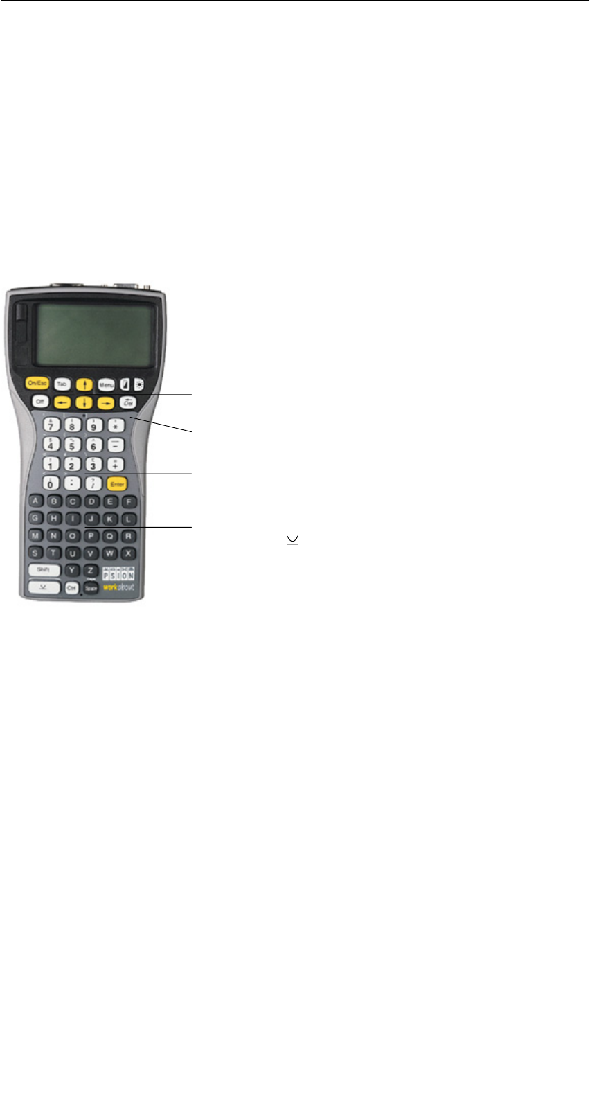
3.1 Keyboard
The keyboard of the PSION is divided into 3 parts.
S11 control keys directly below the display
SNumerical key block with 16 keys
SASCII keyboard (30 keys) including shift key
ASCII keyboard plus shift and special function
keys (Ctrl, )
Control keys: Contrast, display illumination,
on/off, and cursor keys
Numeric input block with Enter key
Green LED. Goes on when battery is being
charged.
Using the STG
R 01.04
E-9
STG Hand-Held Terminal
(5)J31069-D0126-U001-A5.1-7418
3.2 Antenna on the Read Head and Antenna Field
3.2.1 MOBY D/E/F/I
The antenna of the read head is located on the top of the hand-held terminal as
shown in the figure below.
Reading an MDS
The various types of MDSs offer different ranges. The following table gives you
an overview.
MOBY D MOBY E MOBY F MOBY I
MDS Type mm MDS Type mm MDS Type mm MDS Type mm
D139 60 E600
(ISO card)
18 F125 80 402/401 6
D160 25 E611 30 F415 50 404/514/413E 20
Labels based on
Bi ICd
3
E624 (button) 8 F124 60 403 8
Basis I-Code:3E623 (pill)14/32506 12
I-Code1 75 439E 12
I-Code SLI 100 507
(ih b )
35
Tag-it HF-I 100 (with battery)
my-d 100 507 (without
battery)
4
1 The pill can only be read on the head portion provided for this.
2 When MDS is installed in metal
3 Range tolerances are to be expected for manufacturing reasons. The distances apply
to labels with the size 85 x 55 mm.
Using the STG

R 01.04
E-10 STG Hand-Held Terminal
(5)J31069-D0126-U001-A5.1-7418
Example:
MDS E600
Example:
MDS E623
MOBY D/E/F MOBY E/I
Button antenna or
rod antenna (MOBY I)
Surface
antenna
The antenna field for the STG read head
Antenna field for MOBY E
With the MOBY E read head, 2 antennas are integrated in the reader. These
must be positioned on the read head based on which MDS you want to read.
The EXTRAS/ANTENNE command (see chapter 4.5.3) is used to switch the
antenna field. Remember that the MDS E623 can only be read on the antenna
provided for this. See figure. The MDS E624 can be read on both the button
antenna and the surface antenna.
Using the STG

R 01.04
E-11
STG Hand-Held Terminal
(5)J31069-D0126-U001-A5.1-7418
3.2.2 MOBY U
The actual antenna of the STG U hand-held terminal is located on the back of
the MOBY U antenna (see photo below). This means that the direction of emis-
sion is vertical to the back of the MOBY U antenna. The cone-shaped antenna
field has an opening angle of approx. 90 degrees. The maximum field length
(limit distance) is 3 meters. It can be set in increments of 0.5 m in the “Extras”
menu.
Back of the MOBY U antenna
Antenna
Using the STG
R 01.04
E-12 STG Hand-Held Terminal
(5)J31069-D0126-U001-A5.1-7418
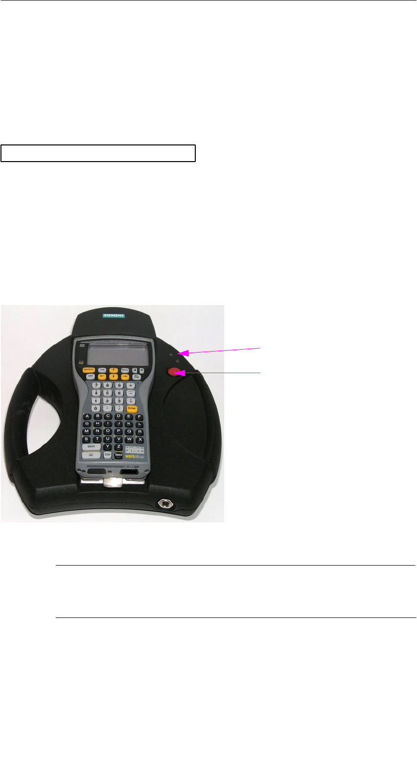
3.3 Using the MOBY U Antenna
The MDS functions (e.g., read, write, initialize) are not triggered on the STG U
hand-held terminal until the communication button is pressed.
The “Menu” button is used to select the appropriate MDS function. The follo-
wing message appears on the display.
ESC to cancel
Wait for ENTER of antenna
Then point the STG U hand-held terminal to the desired MDS Uxxx and press
the communication button.
After the communication button is pressed, the antenna goes on, the MDS
function is executed, and the antenna goes off again. As long as the antenna is
active, the LED for communication is yellow. It takes approx. 2 seconds to turn
on the antenna. Depending on the amount of data and the recognition of the
MDS, turn on takes a minimum of approx. 3 seconds.
STG U hand-held terminal
LED for communication
Communication button
Note
The LED communication lights up red when the charging status of
the batteries is not sufficient for communication.
Using the STG

R 01.04
E-13
STG Hand-Held Terminal
(5)J31069-D0126-U001-A5.1-7418
3.4 Charging Function
The battery charging procedure is started as soon as the PSION Workabout is
placed in the wall or vehicle holder. Charging is activated and indicated with a
green LED. See chapter 3.1.
When the batteries are empty, at least 14 hours are required for a complete
charge.
High-speed battery charging
The batteries supplied by Siemens for the PSION Workabout can be charged at
high speed so that the MOBY hand-held terminal can be operated directly in
the high-speed charging device available from PSION. A full charge takes
1 hour.
Use of other batteries
Other AA batteries can also be used in the PSION Workabout. These include
rechargeable NiCd batteries and alkali batteries which cannot be recharged.
IMPORTANT: Be sure to adhere to the PSION user’s manual.
The backup battery
The backup battery in the PSION Workabout is used to retain the application
data when the main batteries are empty. The backup battery is a lithium cell
which cannot be charged. Remember that, when the main batteries are empty
or have been removed, a new backup battery can only maintain the data in the
RAM for just a few days.
Using the STG
R 01.04
E-14 STG Hand-Held Terminal
(5)J31069-D0126-U001-A5.1-7418
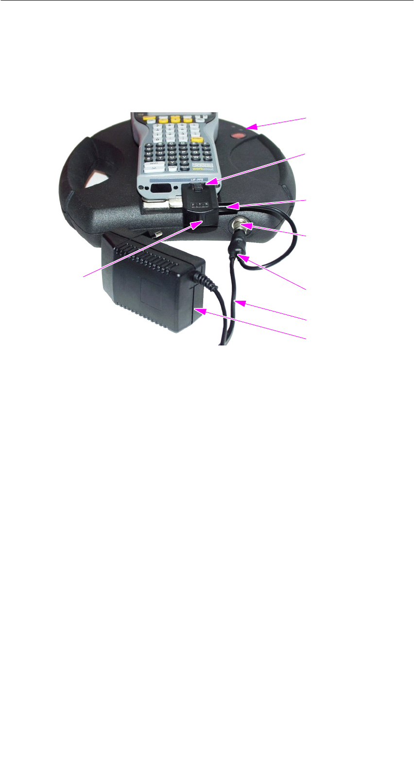
Charging STG U hand-held terminal
The batteries of the STG U hand-held terminal (in the PSION Workabout and
the MOBY U antenna) can be charged with only one power pack
(6GT2 503-1DA00).
The STG U hand-held terminal with connected power pack for charging
the batteries
LED for charging
the batteries
Charging socket
of the PSION
Workabout
Plug for the
charging adapter
Charging socket
of the MOBY U
antenna
Cable switch on
the charging cable
Charging cable
Power pack
Charging adapter
for the PSION
Workabout
Proceed as shown below to connect the power pack to charge the batteries.
SPlug charging adapter into the charging socket of the PSION Workabout.
SPlug connector on the cable switch of the charging cable into the charging
socket of the MOBY U antenna.
SPlug connector for charging adapter on the charging cable into the charging
adapter.
SConnect power plug of the power pack.
The charging status of the battery pack of the MOBY U antenna is indicated by
the LED for charging the batteries.
SYellow: The battery pack of the MOBY antenna is being charged.
SGreen: The battery pack of the MOBY antenna is charged.
SRed: The device is defective.
On the PSION Workabout, a green LED (see chap. 3.1) is on during charging.
Using the STG

R 01.04
E-15
STG Hand-Held Terminal
(5)J31069-D0126-U001-A5.1-7418
When batteries are empty, duration of charging is:
SAt least 1.5 hours for the MOBY U antenna
SAt least 14 hours for the PSION Workabout.
The STG U hand-held terminal can also be used during charging.
Note
SThe PSION Workabout can only be charged when it is equipped
with original PSION batteries.
SA restricted temperature range must be adhered to when the bat-
tery pack of the MOBY U antenna is being charged:
0 °C to +40 °C.
Using the STG

R 01.04
E-16 STG Hand-Held Terminal
(5)J31069-D0126-U001-A5.1-7418
3.5 Changing the Battery Pack of the MOBY U
Antenna
The battery of the MOBY U antenna is a lithium ion battery pack. It has a life-
span of approx. 500 charging cycles.
When the capacity of the battery pack has decreased to the point that the ope-
rating time of the MOBY U antenna is no longer sufficient for the application, it
is time to replace the battery pack.
Disconnect the 9 screws on the back of the housing shell of the antenna and
remove the shell. Replace the battery pack. Replace the housing shell and
screw it tight.
Note
SThe power pack may not be connected on the STG U hand-held
terminal while the battery pack is being replaced.
SThe PSION Workabout does not need to be separated from the
MOBY U antenna although it must be turned off during replace-
ment.
Note
The replacement battery pack for the MOBY U antenna has the
order number 6GT2 594-0AB00.
!Warnung
The battery pack of the MOBY U antenna and the replacement
battery pack consist of lithium ion batteries. The following must be
adhered to when handling these batteries.
SAvoid risk of fire, explosion and severe burns.
SDo not expose the battery pack to temperatures in excess of
100 °C.
SDo not take the battery pack apart or destroy it.
Incorrect handling, damage or contact with water may cause the
battery pack to explode.
SAdhere to national regulations when disposing of used recharge-
able batteries/batteries.
Using the STG

R 01.04
E-17
STG Hand-Held Terminal
(5)J31069-D0126-U001-A5.1-7418
4 The “MOBY D/E/F/I/U” Programs
After you turn on the STG, the editor appears on the display. You can view the
data, enter new data or call a function with the “Menu” key. Functions can also
be called directly with the key. To do this, press the key and the appropri-
ate alphanumeric key at the same time. The table below lists all functions to-
gether with their direct calls.
Command Shortcut Description
File/Load File L or F31Load file from PSION RAM drive to work-
ing storage
File/Save S or F41Store read MDS data on the RAM drive
File/Exit X Exit STG application
Tag/Read R or F11Read data from MDS
Tag/Write W or F21Write data to MDS
Tag/Erase/initialize E Write MDS with a certain value
Tag/Tag status O3Read MDS status
Tag/Read TagId TRead ID number of MDS
Tag/Read OTP F3Read data from OTP memory
Tag/Write OTP H3Write data to OTP memory
Tag/Read raw data M2Read physical memory of MDS
Editor/Jump to address J or Tab Jump to a certain address in editor
Editor/Display D Change display options
Editor/Clear C Clear data in editor to a certain value
Editor/edit date AThe date on which the cursor is posi-
tioned can be edited in a number of for-
mats.
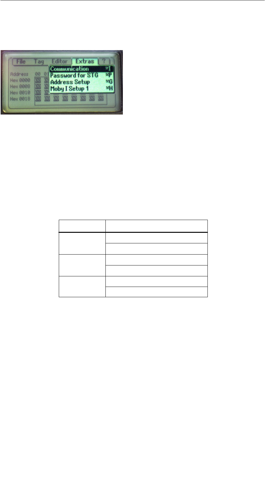
Extras/Communication I Change communication options
Extras/Password for STG PChange password for STG application
Extras/Address Setup GDefine entries for the “read/write MDS”
commands
Extras/MOBY I Setup HSet memory size and MOBY I operating
mode
The “MOBY D/E/F/I/U” Programs

R 01.04
E-18 STG Hand-Held Terminal
(5)J31069-D0126-U001-A5.1-7418
Command DescriptionShortcut
Extras/MOBY E Setup YSwitch MDS access from “MOBY key” (A)
to the B key
For MOBY E SIM: Switch between cyclic
operation and continuous operation
Extras/MOBY U Setup K3Define MDS memory size and range limit
Extras/SLG status Q3Read status of MOBY U antenna
?/Language N Set menu language
?/About... B Manufacturer’s data
?/Version V Version of operating system and STG
application
1 These keys are only available on a hand-held terminal with a numeric keyboard.
2 Not MOBY U
3 Only MOBY U
The “MOBY D/E/F/I/U” Programs
R 01.04
E-19
STG Hand-Held Terminal
(5)J31069-D0126-U001-A5.1-7418
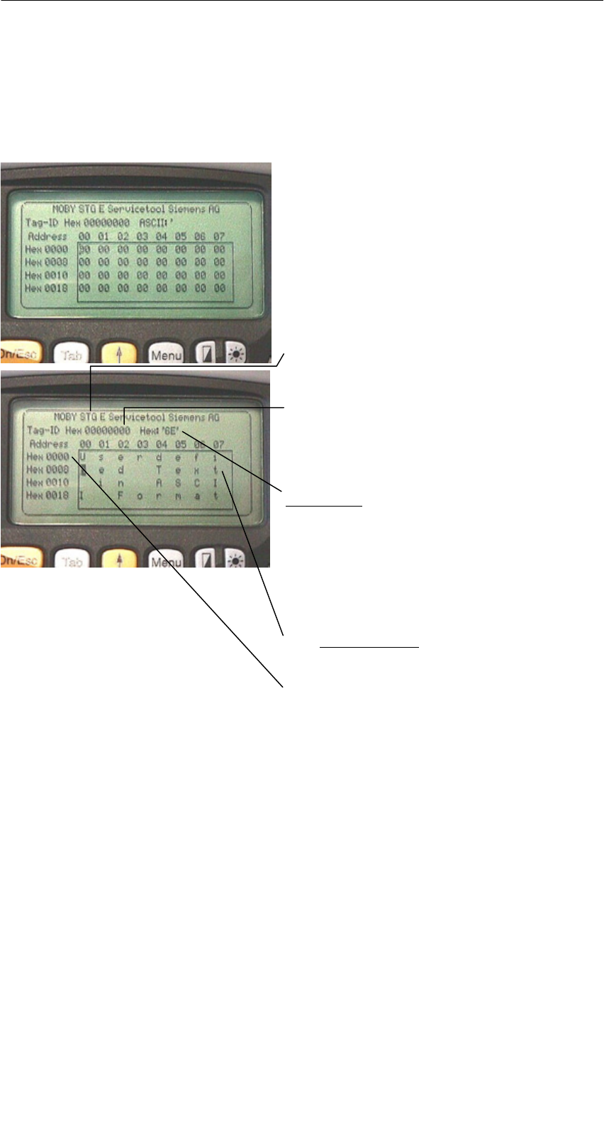
4.1 Data Editor
The MDS data can be edited in hexadecimal or ASCII in the editor screen. This
can be set in the EDITOR/DISPLAY menu.
The editor always shows the total size of
an MDS memory. Use the cursor func-
tions to access the individual addresses.
Use the “Tab” key to jump to any ad-
dress. See chapter 4.4.1.
Indication of the currently set read head.
Cf. chapter 4.5.1
The TagId of the MDS is only displayed
on the MOBY E/F/D/U. It is valid after
the “MDS/read-write-readTagId” function
is executed.
Date field:
The date on which the cursor is located
can also be shown in hexadecimal,
decimal, ASCII or binary format. The
“Editor/edit date” function can be used to
change the value in the date field.
The editor screen contains the MDS date.
Standard setting is 32 bytes.
MDS addresses are shown in hexadeci-
mal or decimal format.
The “MOBY D/E/F/I/U” Programs
R 01.04
E-20 STG Hand-Held Terminal
(5)J31069-D0126-U001-A5.1-7418
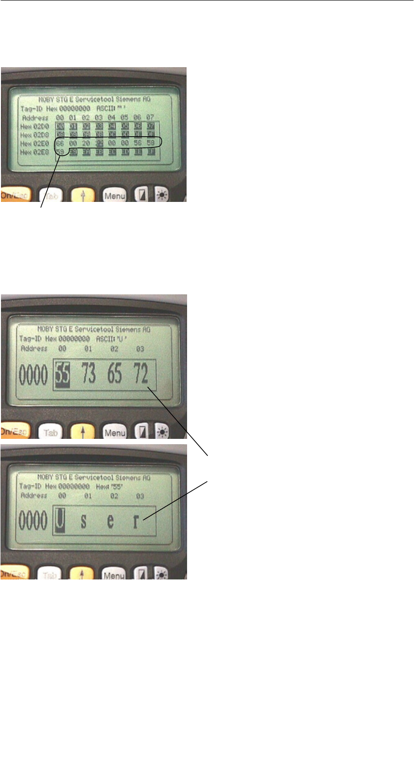
The “current area”
Current area
The editor uses normal representation
for the “current area.” All other data
areas of the MDS are shown inverted.
The current area shows the data block
which was read last. During read/write-
accesses, the current area is entered as
the value for the write command.
This value can be adjusted in the
TAG/WRITE or TAG/READ menu.
The current area is changed automatically when you edit data and overwrite.
The size of the memory area shown on the display can be switched
with the EDITOR/DISPLAY function. See chapter 4.4.2.
In the normal representation, 32 bytes
are displayed in lower case letters. This
gives you an overview of the MDS data.
In zoom representation, only 4 consecu-
tive bytes are shown. Representation is
in upper case letters. This display is
easy to read.
Zoom representation (hexadezimal)
Zoom representation (ASCII)
The “MOBY D/E/F/I/U” Programs
R 01.04
E-21
STG Hand-Held Terminal
(5)J31069-D0126-U001-A5.1-7418
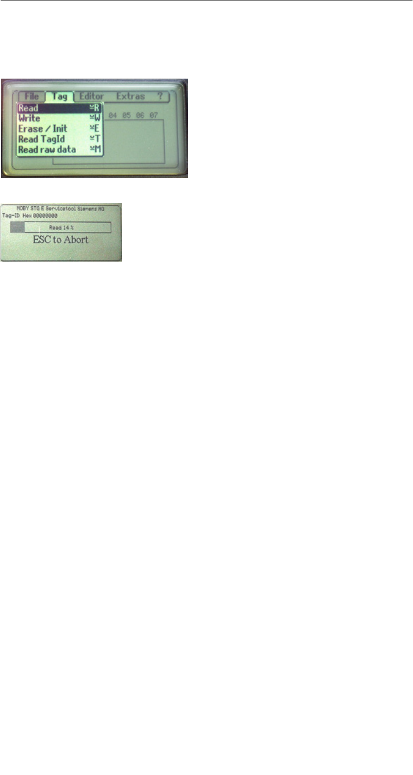
4.2 MDS Functions
After a command is started, a window
with a bar appears on the display. This
bar shows how much of the command
has already been processed.
The MDS functions handle communica-
tion with the MDS.
The MDS function is not interrupted if
you briefly move the MDS out of the
read field. The MDS function is termi-
nated if MDS processing does not take
place for more than 30 seconds. See
chapter 4.5.
4.2.1 General Information on Read and Write-Accessing
an MDS
The MOBY D, MOBY E and MOBY F MDSs use block-oriented data accessing.
A read or write-access to an MDS is only possible at the beginning of a block.
One block contains 16 bytes (or 10 hex) with MOBY E/F. Thus, the start
addresses for MDS processing to be entered on the STG are:
00, 10, 20, 30 hex and so on.
With MOBY D a block has a length of 4 bytes (I-Code, Tag-it) or 8 bytes (my-d).
The start addresses are:
00, 04, 08, 12 hex ... (I-Code, Tag-it) or
00, 08, 10, 18 hex ... (my-d).
With the MOBY D/E/F/U, the TagId on the display is automatically updated to
the current value after the read/write access.
The “MOBY D/E/F/I/U” Programs

R 01.04
E-22 STG Hand-Held Terminal
(5)J31069-D0126-U001-A5.1-7418
However, you can also specify any start address.
This will be accepted by the STG and corrected to
the next lower block beginning. The corrected ad-
dress is indicated for the operator in a window and
must be acknowledged.
An additional window appears if you change data in
the editor and then attempt to read an MDS. The
window tells you that the data which you have just
modified may be overwritten again with the “read
MDS” command. You can retain or reject the modi-
fied data in the editor, or you can terminate the com-
mand completely.
Note
ECC mode can only be set on the MOBY I hand-held terminal.
ECC mode cannot be used with MOBY D/E/F/U.
4.2.2 Reading the MDS
A data block with a start and end address, which can be defined as desired,
can be read from the MDS. If the same value is entered for the start and end
address, only one block can be read from the MDS. The address area is indi-
cated in another screen for confirmation.
Note
If mode “Complete MDS” was selected in the read/write field of the
menu “Extras/Address Setup/...,” the “MDS/read” funktion is started
immediately without asking any questions. The complete MDS is al-
ways processed.
The “MOBY D/E/F/I/U” Programs

R 01.04
E-23
STG Hand-Held Terminal
(5)J31069-D0126-U001-A5.1-7418
4.2.3 Writing the MDS
A data block can be written to the MDS. The data block which is valid in the
editor is indicated as the default for each write access. The default length or
end address can still be changed to another value during the write-access.
4.2.4 Erasing/Initializing the MDS
The “erase/initialize MDS” function is used to write the entire MDS with a
certain value in a very short time. The erasure value can be entered in a
subsequent menu. After the deletion function has been performed, the memory
in the editor is also erased with the value which was entered. With the
MOBY I/U, the correct size of the MDS memory must be set (Extras/MOBY I
Setup or Extras/MOBY U Setup) before this function is performed.
The “MOBY D/E/F/I/U” Programs

R 01.04
E-24 STG Hand-Held Terminal
(5)J31069-D0126-U001-A5.1-7418
4.2.5 Reading MDS Status
Only MOBY U: The function reads the status data from the MDS and indicates
it.
MDS status information
SMDS number (8-position, hexadecimal format) and MDS memory size (2 or
32 kB)
SData for calculation of the battery lifespan (total accesses, total search, and
change sleep time)
SRemaining battery life time of the MDS in %
SSleep time set on MDS
Note
For calculation of the battery lifespan of the MOBY U data medium,
it is essential that the STG software have the current calendar week
and the current calendar year. This is the reason the date must be
set correctly on the PSION Workabout.
The date can be set via the system menu “Time” → “Time and date.”
Proceed as shown below.
SExit the MOBY U service and test program via “File/Exit.”
SSelect “System screen.”
SPosition the cursor on the application “IMG.”
SClick the “Menu” button.
SSelect “CTRL/Set time and date.”
SSet “Time” and “Date” and accept with “Enter” button.
SReturn to the MOBY U service and test program via “IMG” and
“Moby_u[A].”
The “MOBY D/E/F/I/U” Programs

R 01.04
E-25
STG Hand-Held Terminal
(5)J31069-D0126-U001-A5.1-7418
4.2.6 Reading the ID Number
Only MOBY D/E/F/U: The function reads and indicates the serial number of the
MDS. The ID number is set at the factory and cannot be changed.
The TagId is displayed in hexadecimal format by the editor in the second line.
The TagId is automatically read with the “MDS read/write/erase” functions.
4.2.7 Reading OTP Memory
Only MOBY U: The function reads the complete OTP memory (16 bytes).
Note
When the mode “MDS complete” was selected in the “Read/write”
field in the “Extras/Addresses Setup/...” menu, the function “MDS/
Read” is started immediately without any further questions. The
entire MDS is always processed.
4.2.8 Writing OTP memory
Only MOBY U: The function writes the complete OTP memory (16 bytes).
Note
The OTP memory can be written only once. Before execution, you
are asked again whether you really want to execute the function
since this action is irreversible.
The “MOBY D/E/F/I/U” Programs

R 01.04
E-26 STG Hand-Held Terminal
(5)J31069-D0126-U001-A5.1-7418
4.2.9 Reading Raw Data
Only MOBY D/E/F: This function is used to physically read the entire memory of
the MDS. This includes TagId, key information (if public), manufacturer’s
information and MDS access rights. A knowledge of the physical layout of the
MDS memory is required to interpret the data. See description of MFWAPI or
CCTWAPI.
The “read raw data” function can be used to detect errors made when the MDS
was configured.
Note
For MOBY F
MDS addresses 8 to 3F hex (i.e., pages 2 to 15) cannot be read.
They are always shown by the editor as 00.
The “MOBY D/E/F/I/U” Programs

R 01.04
E-27
STG Hand-Held Terminal
(5)J31069-D0126-U001-A5.1-7418
4.3 File Functions
4.3.1 Loading a File
A file can be loaded to the STG editor which was
Ssaved before with the “file/save” command or
Stransferred from the PC to the “RAMDRIVE (M:)” drive of the PSION. See
chapter 6.2.
4.3.2 Saving
Data currently being displayed by the editor can be saved in a file on the
PSION. The file name may consist of 1 to 8 letters or numbers. During the
storage procedure, the extension “.HEX” (data) and “.HX1” (ID no.) is
automatically added to the file name. See also chapter 6.2.
A memory area of approximately 1.8 Mbytes is available on the hand-held
terminal for storage of MDS data (i.e., with MOBY E, up to 2000 MDSs can be
read and stored).
4.3.3 Exiting
The “exit” function can be used to conclude the STG program of MOBY. This
gives you access to the operating system levels of the PSION hand-held
terminal. See chapter 6.3.
The “MOBY D/E/F/I/U” Programs

R 01.04
E-28 STG Hand-Held Terminal
(5)J31069-D0126-U001-A5.1-7418
4.4 The Editor Functions
4.4.1 Jump to Address
You can enter a memory address in decimal or hexadecimal format. The
setting can be changed under menu item Display/Display Address. This
address will then be represented by the editor as the start address.
This function can also be triggered directly in the editor with the “Tab” key.
4.4.2 Display
The following settings are available in this menu.
SSwitch the editor between 32-byte representation (i.e., 4x8= fine-print
display) and 4-byte representation (i.e., 1x4= large, easy-to-read
characters).
SNo address is displayed for editor representation 1x5. This display is very
good when reading fixed-code MDSs with the MOBY F. With other MDS
types, the first 5 bytes of the read data are displayed. You cannot change to
other addresses with the cursor.
SSwitch the editor between hexadecimal and ASCII representation. The
addresses are always shown in hexadecimal or decimal format.
SSwitch date between “BIN,” “ASCII,” “DEC” and “HEX” format.
The “MOBY D/E/F/I/U” Programs

R 01.04
E-29
STG Hand-Held Terminal
(5)J31069-D0126-U001-A5.1-7418
4.4.3 Clear Display
The “clear display” function is used to overwrite the entire memory in the STG
editor with a value which you can specify. You can then change the desired
data to the appropriate values in the editor. No function is performed on the
MDS.
SThe data field can be shown in hexadecimal, ASCII, decimal or binary for-
mat. The data can also be changed with the “Indicate/edit date” function with
the format set here.
SThe addresses can be indicated in hexadecimal or decimal.
4.4.4 Edit Date
In addition to the standard formats hex and ASCII of the editor screen, the “edit
date” function also provides the decimal and binary formats for data entry.
The “MOBY D/E/F/I/U” Programs
R 01.04
E-30 STG Hand-Held Terminal
(5)J31069-D0126-U001-A5.1-7418
4.5 The Extras Functions
4.5.1 Communication
SInterface Switching between the TTL interface (read head) and the
RS 232 interface takes place here.
If the RS 232 setting is used, the protocol must be set to
“MOBY E/SIM” or “ASM 420/I/V.”
No setting is required for MOBY U. The interface is
permanently set to RS 232.
SProtocol Certain protocols can be set here depending on which read
head is being used.
Read Head Protocol That Can Be Set
MOBY D
MOBY D ISO
MOBY E
MOBY E/SIM
MOBY I
ASM 420/I/V
MOBY D
MOBY E
MOBY I
When the MOBY protocol is set, the memory size of the editor
is also automatically specified for MOBY E/F.
With MOBY I, the memory size of the editor is set with the
“Extras/MOBY I Setup” function.
The 3964R protocol is permanently set for MOBY U. The
memory size of the editor is set with the “Extras/MOBY U
Setup” function.
The “MOBY D/E/F/I/U” Programs

R 01.04
E-31
STG Hand-Held Terminal
(5)J31069-D0126-U001-A5.1-7418
4.5.2 Password
A password can be programmed as an option. The password must be entered
prior to a write-access function. Once entered, a password remains valid until
the STG is turned off (i.e., the password only has to be entered once during
several consecutive write commands). The “MOBY” program can also only be
exited with the password.
Default password
On delivery, the password is “123.” This password is also set after you remove
the batteries of the STG.
Forgot the password?
If a password is forgotten, there is no way to obtain it again. The only solution
is to remove the main battery and the button cell from the PSION for a few
minutes. After the batteries have been re-installed and the device has been
turned on, the STG assumes its status on delivery (i.e., the password is “123”).
Password 99999999
Changing the password to 99999999 (i.e., eight 9s) has a special purpose.
The write-access function to the MDS and the “file/exit” function can no longer
be executed. The password can also no longer be changed. The only way to
access the write-access function again is to remove all batteries. See also
“forgot the password?”.
4.5.3 Antenna
Only for MOBY E: The antenna field on the read head is switched between
“card” (large antenna) and “button” (small antenna). See also chapter 3.2.1.
The antenna must be set once when the read head is commissioned. The
set antenna is retained on the read head when the hand-held terminal is
turned off.
The “MOBY D/E/F/I/U” Programs

R 01.04
E-32 STG Hand-Held Terminal
(5)J31069-D0126-U001-A5.1-7418
4.5.4 Address Setup
This function defines the call of the “read/write MDS” commands.
SStart address + Length: Entry of the MDS address for the read/
write command uses a start address
and the length of the data to be
processed.
End address: Entry of the MDS address for the read/
write command uses a start address
and an end address.
SRead/Write Switching from “block” to “complete MDS” takes place
here. This setting affects the default setting for
execution of an MDS command.
Block: When an MDS is read/written, the
currently active area is always indicated
as the area to be read/written.
Complete MDS: When an MDS is read/written, the
entire MDS is always processed.
The read/write function is started
immediately. Partial MDS areas cannot
be entered.
The “MOBY D/E/F/I/U” Programs

R 01.04
E-33
STG Hand-Held Terminal
(5)J31069-D0126-U001-A5.1-7418
4.5.5 MOBY I Setup
SMem size: Specifies the memory size of the MDS to be processed
This setting also defines the memory area in the editor.
MDS memory addresses which exceed the memory size
cannot be addressed.
STag type: Distinguishes between RAM/FRAM and EEPROM
The RAM/FRAM setting shows an empty MDS support
battery on the STG.
SECC: Turns the ECC driver on and off
The purpose of the ECC driver is described in the
documentation of the MOBY interface.
SMDS507: This parameter must only be set to “yes” when the
MDS 507 is used. With the MDS 507, the dialog battery
is scanned and indicated as “Status” when it is empty.
SSample rate: The scan time is only relevant when the MDS 507 is
used with an ASM 420. The setting range is 0.1 sec to
6.3 sec. The default value (0.5 sec) usually does not
have to be changed.
4.5.6 MOBY E Setup
SKey A/B: You can switch between the “MOBY key” and the
“B transport key for MIFARE data memory.”
The MOBY key is always standard. The “B” setting
permits the MIFARE MDS to be processed in its status
on delivery. (The B key must be in its original state.)
SMode: Only for MOBY E SIM (cf. chapter 6.6):
Switches the SIM from cyclic mode to continuous mode.
Command processing is much faster in continuous
mode.
SAntenna: You can switch between card and pill.
The “MOBY D/E/F/I/U” Programs

R 01.04
E-34 STG Hand-Held Terminal
(5)J31069-D0126-U001-A5.1-7418
4.5.7 MOBY U Setup
SMemory size: Specify memory size of the MDS to be processed. This
setting can also be used to specify the memory area in
the editor. MDS memory addresses beyond the memory
size cannot be accessed.
SStandby time: The standby time can be set in increments of 7 msec
from 0 msec to 1400 msec. The default value (OFF)
usually does not have to be changed.
SWorking range The field length (limit distance) is 3 m. It can be set in
limitation: increments of 0.5 m to avoid excess working ranges for
the antenna.
The setting range is between 0.5 m and 3.5 m. The
default value is 1 m.
4.5.8 SLG Status
Only MOBY U: The SLG Status function can be used to read version states and
settings of the MOBY U antenna.
The information can be accessed with the “Enter” key in 3 consecutive screens.
SScreen 1: Hardware, firmware and loader version
SScreen 2: Driver model, driver version and interface parameters
SScreen 3: Set working range limitation, standby time and multitagging
(equals 1)
The “MOBY D/E/F/I/U” Programs

R 01.04
E-35
STG Hand-Held Terminal
(5)J31069-D0126-U001-A5.1-7418
4.6 The “?” Functions
4.6.1 Language
German or English can be selected as the menu language with the STG.
During commissioning of the STG, the default language is English.
4.6.2 About
Information on the manufacturer of the STG program:
Siemens AG A&D PT7 M2
4.6.3 Version
Specifies the version of the STG program, the EPOC operating system, the
release status of the ROM version and the release status of the MOBY library.
These parameters must be specified when reporting errors to Siemens.
The “MOBY D/E/F/I/U” Programs

R 01.04
E-36 STG Hand-Held Terminal
(5)J31069-D0126-U001-A5.1-7418
5 The “FILEHANDLER” Program
5.1 General Information on the Filehandler
As with any PC-based system, the filehandler accesses the data with logical file
names and not with physical memory addresses.
The following figure shows the layout of the “FILEHANDLER” program and how
it works.
File 3.hex
File 2.hex
File 1.hex
MOBY\File 3.hex
MOBY\File 2.hex
MOBY\File 1.hex
Optional connection on the PC
WORD
EXCEL
.
.
Editor
display
Directory
display
Files on MDS
Files on hand-held terminal
File 3
File 2
File 1
The “FILEHANDLER” program is designed so that you can use the same func-
tions to access the files on the hand-held terminal and the files on the MDS.
The directory display is available for both the hand-held terminal and the MDS.
MDS files can be copied from the MDS to the hand-held terminal (and vice
versa) with just a few keys.
An optional connection to the PC (3link cable, see appendix A.1) permits you to
exchange files stored on the hand-held terminal with the PC.
You can then process the data with your familiar PC programs (e.g., WORD,
EXCEL, and so on). Prerequisite: The PC application must support the con-
tents and data structure of the MDS file. See also chapter 6.
The “FILEHANDLER” Program

R 01.04
E-37
STG Hand-Held Terminal
(5)J31069-D0126-U001-A5.1-7418
Note
Remember that the filehandler is only available for the MOBY I.
5.2 The Filehandler Commands
STG Command Shortcut1Filehandler
Command
Description
File/Read File from
Tag
R or F12, or
Enter
READ Read a file from the MDS
File/Read File from
STG RAM
S or F32–Read a file from the RAM of
the hand-held terminal
File/Write File to Tag W or F22WRITE Write a file to the MDS
File/Write File to STG
RAM
T or F42–Write the data from the editor
to the hand-held terminal
File/Read Dir from Tag G DIR Read directory from the MDS
and indicate
File/rRad Dir from STG
RAM
P – Indicate directory of the STG
(RAM memory)
File/exit X – Exit filehandler application
Commands/Create
File
B CREATE Create new file with length of
0 on the MDS
Commands/Delete File D or Del3DELETE Delete file from the MDS
Commands/Tag For-
mat
I FORMAT Format the MDS
Commands/File Attrib-
ute
Y ATTRIB Assign access rights to file
on the MDS
Commands/Tag Status FMDS STATUS Read MDS status
Commands/Cover Tag C COVER Protect data structure of the
MDS
Editor/Display Direc-
tory
Q – Display last read directory
Editor/Display Editor U – Display file data
Editor/File Size N – Change file size in editor
The “FILEHANDLER” Program

R 01.04
E-38 STG Hand-Held Terminal
(5)J31069-D0126-U001-A5.1-7418
STG Command DescriptionFilehandler
Command
Shortcut1
Editor/Clear Display J – Write display with certain
value
Editor/
Jump to address
O or Tab –Move cursor to address posi-
tion
Editor/Display Setup H – Switch display between
ASCII and HEX representa-
tion
Extras/Parameter Z – Set filehandler parameters
Extras/Password for
FH
A – Password setting for the
“FILEHANDLER” program
Extras/Communication E – Setting: Read head or ASM
?/Language L – Set menu language
?/About... K – Manufacturer’s data
?/Version V – Version of operating system
and filehandler
1 The key combination + key is used for the shortcuts of the commands. Both keys
must be pressed at the same time. The keys for the shortcuts of the MDS commands
are the same as the letters used to address them in the SIMATIC with FC.
2 Keys F1 to F4 are only available on a hand-held terminal with a numeric keyboard.
3 The “Del” key can be used to delete the file currently selected in the directory view.
This can also be used to delete files from the RAM of the hand-held terminal.
The “FILEHANDLER” Program
R 01.04
E-39
STG Hand-Held Terminal
(5)J31069-D0126-U001-A5.1-7418
5.3 View of the Editor and Directory
The filehandler’s monitor screen display is either “Directory – View” or “Editor –
View.” You can use the menu “Editor/Display Editor” and “Editor/Display Direc-
tory” menu to switch between the two displays.
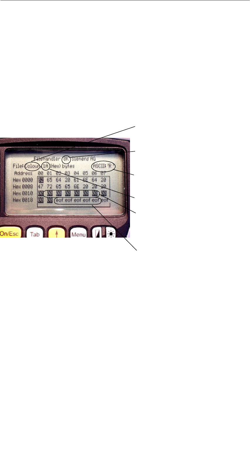
5.3.1 The Data Editor of the Filehandler
The design of the data editor of the filehandler is similar to the standard STG
program. See chapter 4.1.
Set MDS memory size. It can be set
with the command Extras/Parameter.
Name of the file in the editor. The file
can have been read by both the MDS
and the hand-held terminal memory.
The piece of data on which the cursor
is located. Is also shown in ASCII for-
mat.
The file length is shown here.
The data area which is longer than
the file length is marked with the data
string “eof” (end-of-file).
If the file size is too long (see
chap. 5.6.3), the extra data are
shown inverted.
The “FILEHANDLER” Program
R 01.04
E-40 STG Hand-Held Terminal
(5)J31069-D0126-U001-A5.1-7418
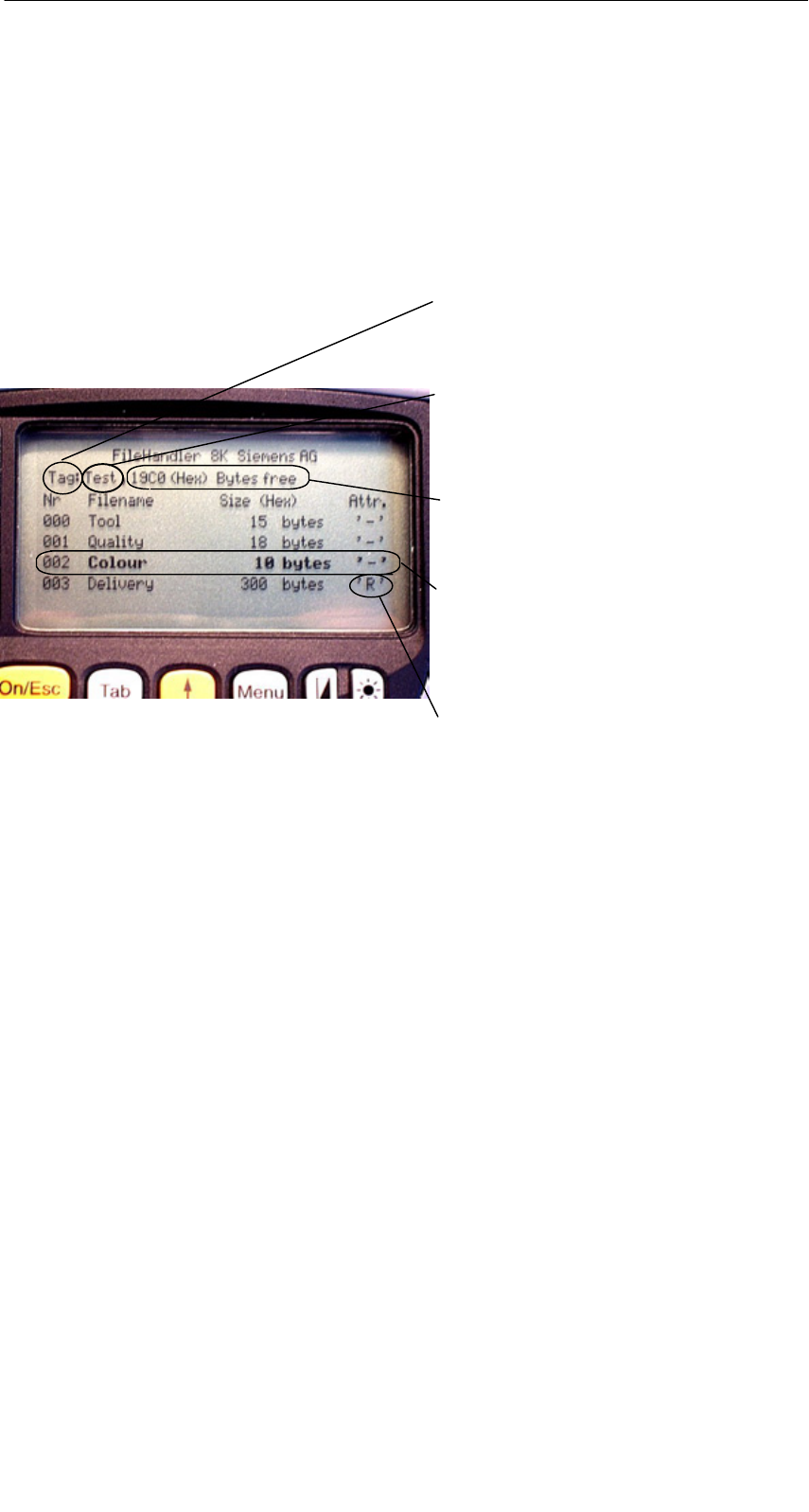
5.3.2 View of the Directory
The directory view shows either all files of the MDS or all files of the STG RAM.
The directory view makes it very easy to read files from the MDS or copy files
between hand-held terminal and MDS. See chapter 5.4.
Layout of the directory
Indication of whether the displayed di-
rectory is from an “MDS” or from the
“hand-held terminal”
Name with which the MDS was for-
matted. No name is indicated for the
hand-held terminal’s directory.
Free memory on the MDS. With the
hand-held terminal, this is approx.
1.8 MB (after the terminal has been
commissioned).
A file can be selected with the cursor
keys. After selection, a function can
then be directly executed with this file.
See chapter 5.4.
An attribute can be entered here for
the MDS files (see chap. 5.5.4). No
attributes can be set for hand-held
terminal files.
The “FILEHANDLER” Program
R 01.04
E-41
STG Hand-Held Terminal
(5)J31069-D0126-U001-A5.1-7418
5.4 The File Functions
The file menu primarily contains three functions which can be called.
SRead file
SWrite file
SRead and display directory
These functions can be executed on both the MDS and the internal memory of
the hand-held terminal.
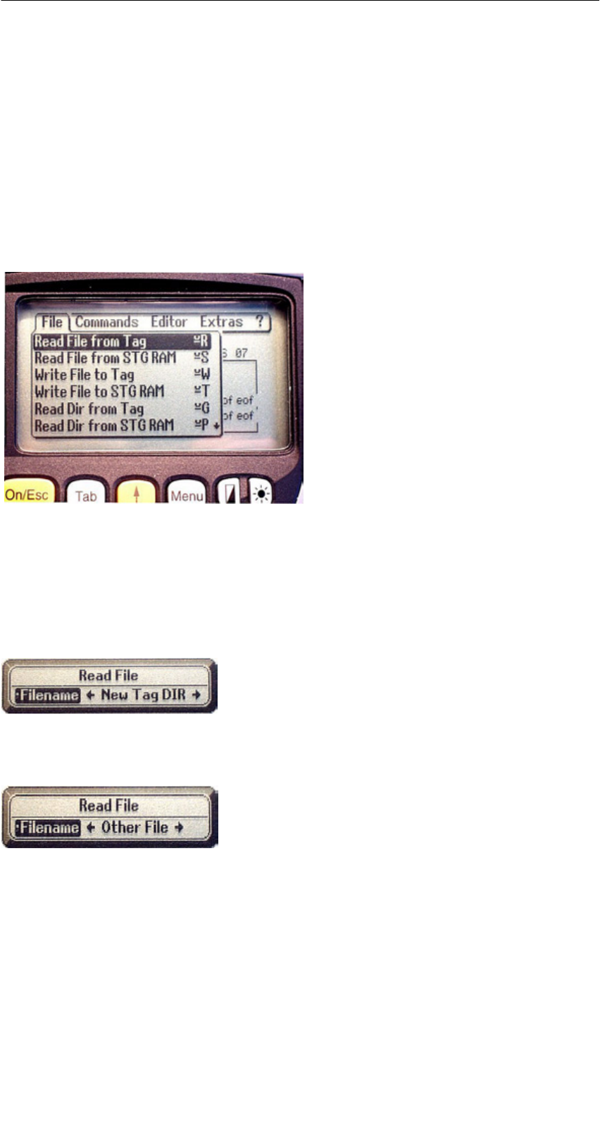
5.4.1 Read File from MDS (Read File from Tag)
After this function has been called, a menu appears in which you can select a
file with the cursor keys. All file names can be scrolled through, including the
ones in the directory view (see chap. 5.3.2).
After you have scrolled through all the files,
the file name “New Tag DIR” appears. If you
press the Enter key, the filehandler reads a
directory from an MDS.
You can then select one of the new files
If you continue paging through the file selec-
tion menu until the file name “Other File” ap-
pears, you can enter a file name (with the
ASCII keyboard of the hand-held terminal) in
the menu which appears.
The “FILEHANDLER” Program
R 01.04
E-42 STG Hand-Held Terminal
(5)J31069-D0126-U001-A5.1-7418
5.4.2 Read File from STG RAM
After this function is called, a menu appears in which you can select a file with
the cursor keys. All file names in the RAM of the hand-held terminal with the
file extension .HEX are displayed. If the STG RAM does not contain any files
with the extension .HEX, the message “No file available” appears.
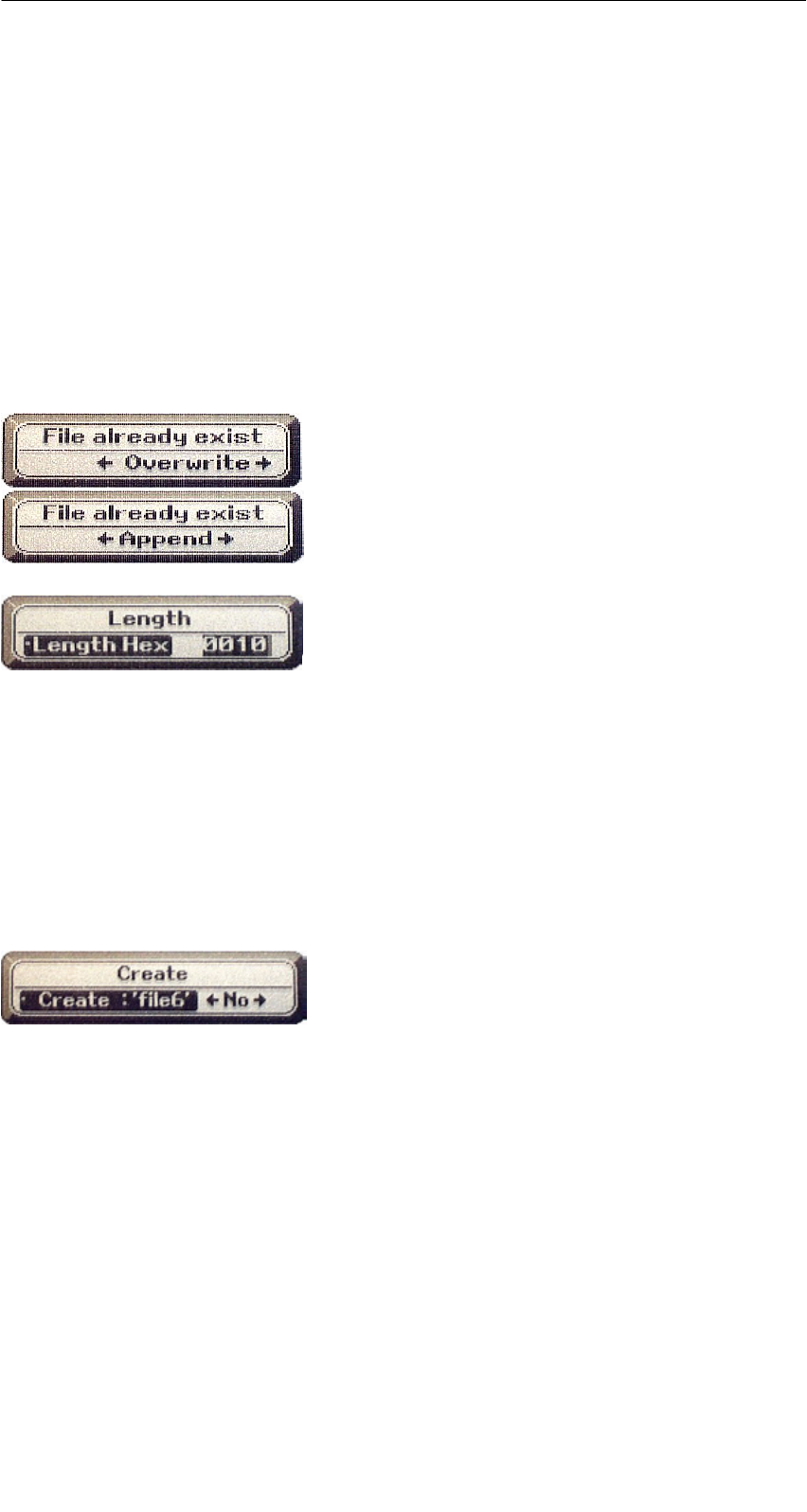
5.4.3 Write File to MDS (Write File to Tag)
The file name is entered as described in chapter 5.4.1. After a file name con-
tained in the directory is entered, you are given the following choices.
You can overwrite the file or append the new
data to the existing file.
In the next screen, you can still change the
length of the data to be written.
The default length is always given as the
value of the length of the data in the editor. If
you change the default length, the data
length on the MDS will also be adjusted.
If you selected the “Append” data option, the file is automatically read again af-
ter execution of the write function. This gives you the complete updated file on
the editor.
If you selected the file name “Other File” when you called the write function and
entered a new file name with the keyboard, the “Create” screen appears.
If you confirm this screen with “Yes,” a new
file is created on the MDS before the data are
written to the MDS.
The “FILEHANDLER” Program

R 01.04
E-43
STG Hand-Held Terminal
(5)J31069-D0126-U001-A5.1-7418
5.4.4 Write File to STG RAM
When a file is saved, the file name indicated in the editor is also indicated as
the default name. You can still change the file name before saving the file. The
file name may contain up to 8 characters. When the file is saved, the file exten-
sion .HEX is automatically added to the file name.
5.4.5 Read Directory from MDS (Read Dir from Tag)
The file directory of an MDS is read and indicated on the display in the directory
view (see chap. 5.3.2). With some MDS types, this may take several seconds.
5.4.6 Read Directory from STG RAM (Read Dir from STG
RAM)
The file directory of the hand-held terminal’s RAM (drive M:) is read and indi-
cated on the display in the directory view (see chap. 5.3.2). Only type *.HEX
files are shown on the display. Also, only files located in the root directory of
the hand-held terminal’s RAM are indicated on the display.
The “FILEHANDLER” Program
R 01.04
E-44 STG Hand-Held Terminal
(5)J31069-D0126-U001-A5.1-7418
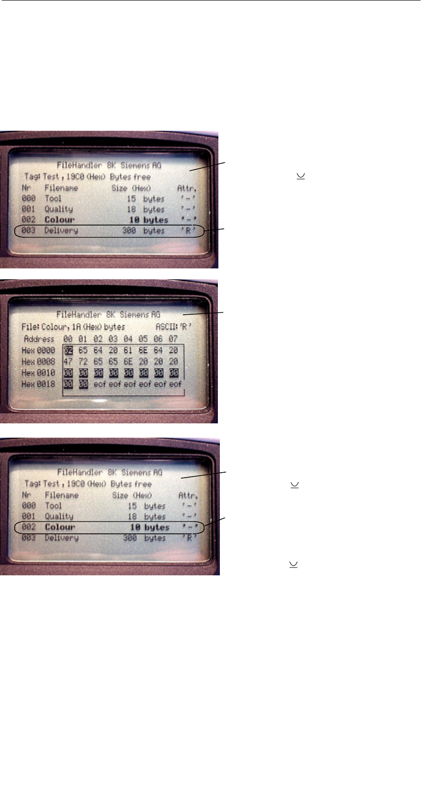
5.4.7 Example: Copy Files
The functions described in this chapter make it very easy to copy files. Files
can be copied from MDS to MDS or from STG RAM to MDS. The procedure for
copying a file from a first MDS to a second MDS will now be described:
1. The function “File/Read Dir
from Tag” ( + G) is executed.
4. The “Editor/Display Directory”
function ( + Q) is executed.
5. The cursor keys " # select the file
to be written.
6. The “File/Write File to Tag”
function ( + W) is executed.
After these functions have been execu-
ted, the “delivery” file is copied to “co-
lour.” The “colour” file now also appears
with a size of 300 bytes.
3. Press “Enter”. After being read,
the data are displayed in the editor
screen.
2. The cursor keys " # select the
file to be read.
The “FILEHANDLER” Program
R 01.04
E-45
STG Hand-Held Terminal
(5)J31069-D0126-U001-A5.1-7418
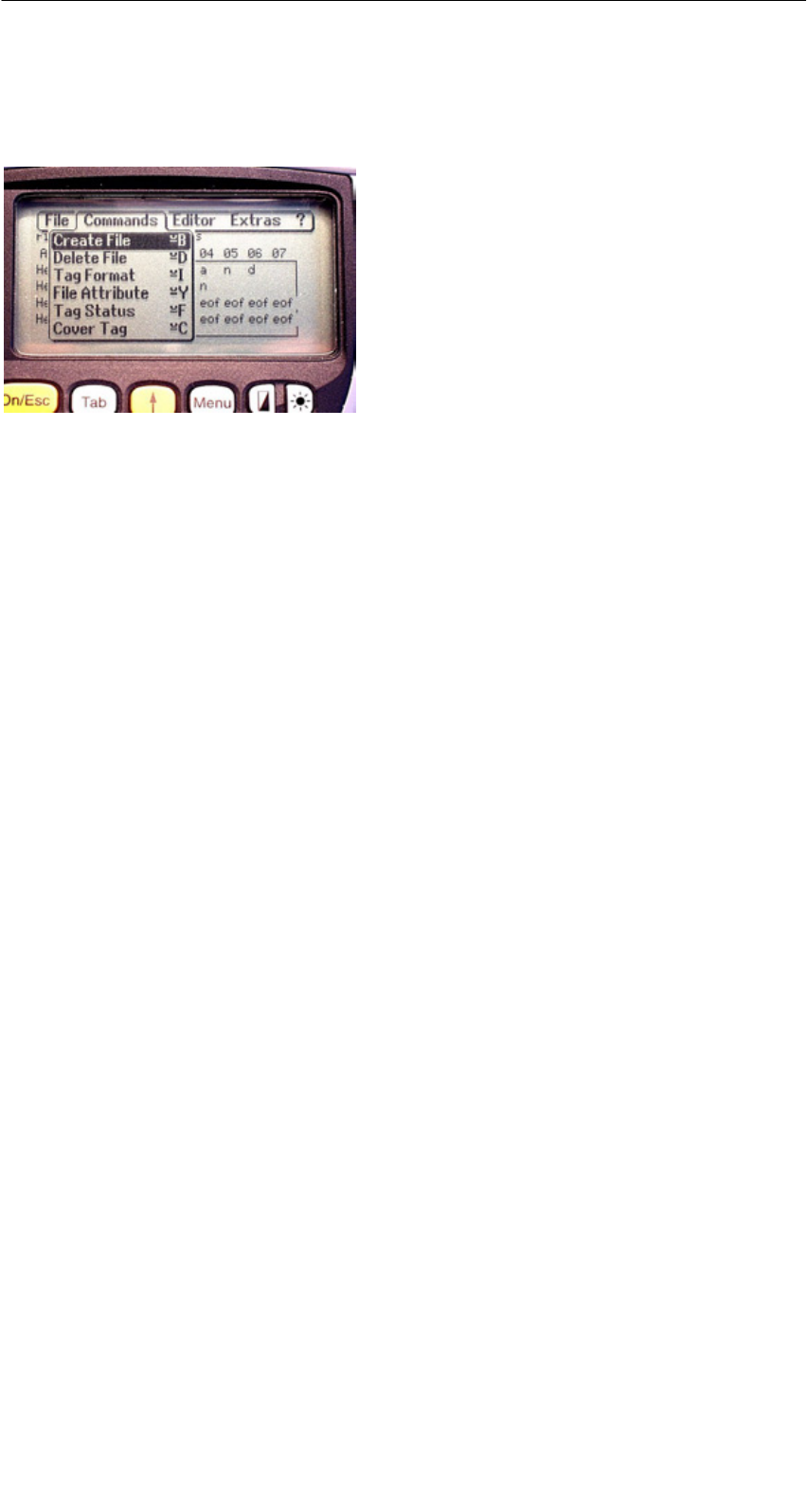
5.5 The Commands Menu
The “Commands” menu contains only
commands related to the MDS memory.
5.5.1 New File (Create File)
“Create File” is used to set up a new file on the MDS. The file name may not
yet exist on the MDS. The new file is always given a length of 0.
5.5.2 Delete File
This function deletes a file from the MDS memory.
If you are in the directory view, it is very easy to start the delete function by
pressing the “Del” key. You can use the “Del” key to delete files from the MDS
or the hand-held terminal. The files are deleted from the hand-held terminal if
the STG files are being shown in the directory view.
5.5.3 Format MDS (Tag Format)
Before it can be used with the filehandler, the MDS must be formatted. Before
formatting, it is important to set the memory size of the MDS correctly. Use the
Extras/Parameter function for this. Formatting deletes all data from the MDS,
and a new file structure is set up.
The “FILEHANDLER” Program

R 01.04
E-46 STG Hand-Held Terminal
(5)J31069-D0126-U001-A5.1-7418
5.5.4 Attribute File (File Attribute)
This command can be used to assign access rights to the individual files. This
protects the files from unauthorized and unintentional overwriting. The direc-
tory view shows the file attribute in the right-hand column (see chap. 5.3.2).
The following file attributes are available.
Attribute Description
–No attribute or an existing attribute is deleted.
RRead only. The file can only be read. It cannot be written, overwritten
or deleted.
WWrite once. The file can be written once. The file cannot be written
again. It also cannot be deleted.
FFixed length. The file can be read as often as desired. It can only be
written when this does not change the length of the file. Data cannot
be appended, and the file cannot be deleted.
F/R “Fixed length” and “read only” are set. This attribute has the same
effect as the “R” attribute.
File attributes can only be assigned to MDS files. Files on the RAM of the
hand-held terminal always have the type “–” (i.e., they can always be changed
or deleted).
The “FILEHANDLER” Program
R 01.04
E-47
STG Hand-Held Terminal
(5)J31069-D0126-U001-A5.1-7418
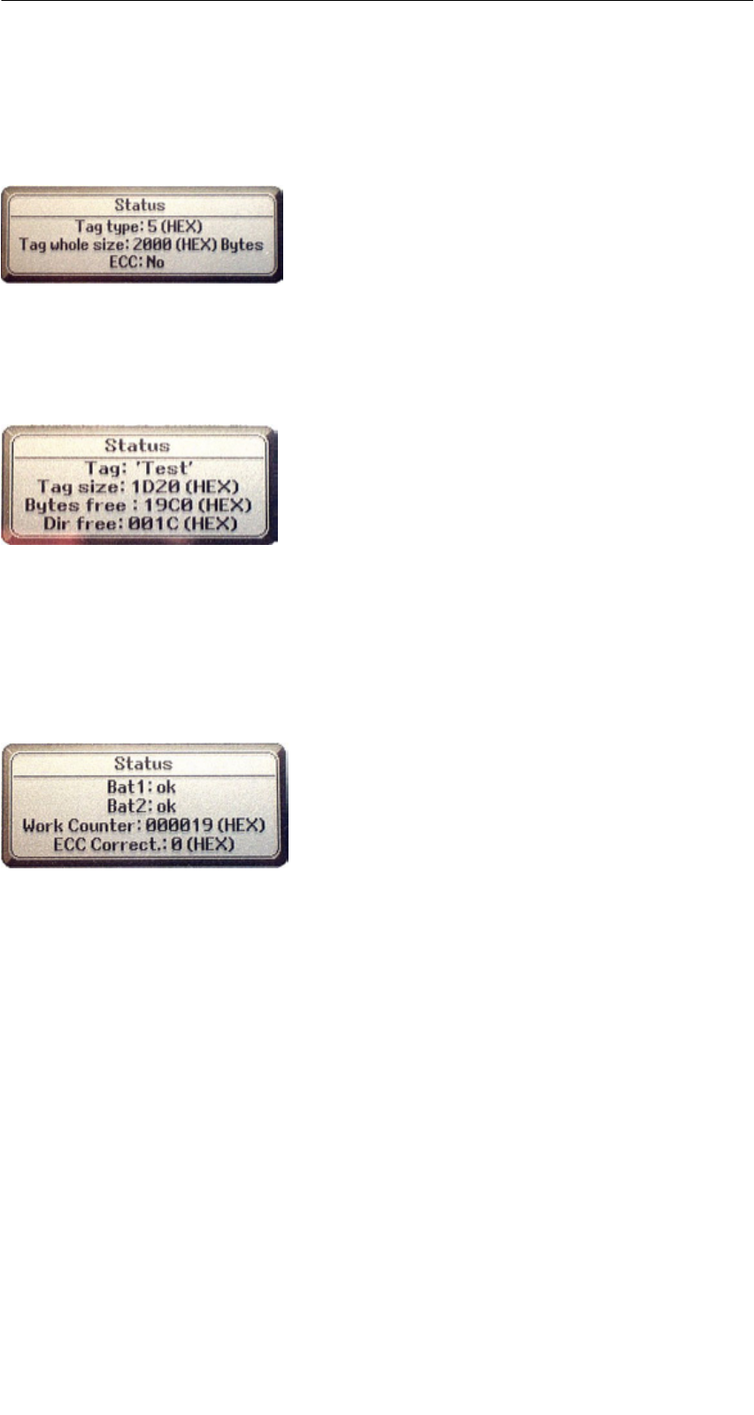
5.5.5 MDS Status (Tag Status)
This command shows the status of the MDS in several consecutive screens.
MDS type (Tag type)
This value is identical to the specification of the
MDS type with the Format command on a SIMATIC.
Gross MDS size (Tag whole size)
The size of the MDS which was set with the Format
command is indicated.
ECC
Indicates whether the MDS is used with or without
ECC
MDS (Tag)
Indicates the name of the MDS which was written to
the MDS with the Format command
MDS size (Tag size)
Indicates the maximum memory area which can be
used by the user
Bytes free
Indicates the number of data bytes on the MDS
which the user can still use for his/her data
Directory free (Dir free)
Indicates the number of files which can still be set
up on the MDS
Battery 1 (Bat1)
Status of the RAM battery. This value does not ap-
ply to the EEPROM MDS.
Battery 2 (Bat2)
Status of the dialog battery with MDS 507
Amount of processing (Work Counter)
Number of processing procedures which were per-
formed with the MDS since it was initially formatted.
This value is particularly important for the EEPROM
MDS since the number of write-accesses is limited
for these types of memory.
ECC Correct
Counter for the number of ECC offsets performed.
If this counter has a value other than zero, the MDS
must be replaced in the near future. An EEPROM
memor
y
was write-accessed too often.
The “FILEHANDLER” Program
R 01.04
E-48 STG Hand-Held Terminal
(5)J31069-D0126-U001-A5.1-7418
5.5.6 MDS Cover
The Cover command protects the entire file structure on the MDS. If an MDS is
“covered”:
SEvery file can be read.
SEvery file can be written as long as the file length is not changed.
SNo files can be deleted.
SNo new files can be created.
SThe format of the MDS can be initialized again. This “uncovers” the MDS.
SThe “covered” state can be canceled with a Cover command and the setting
“not covered.”
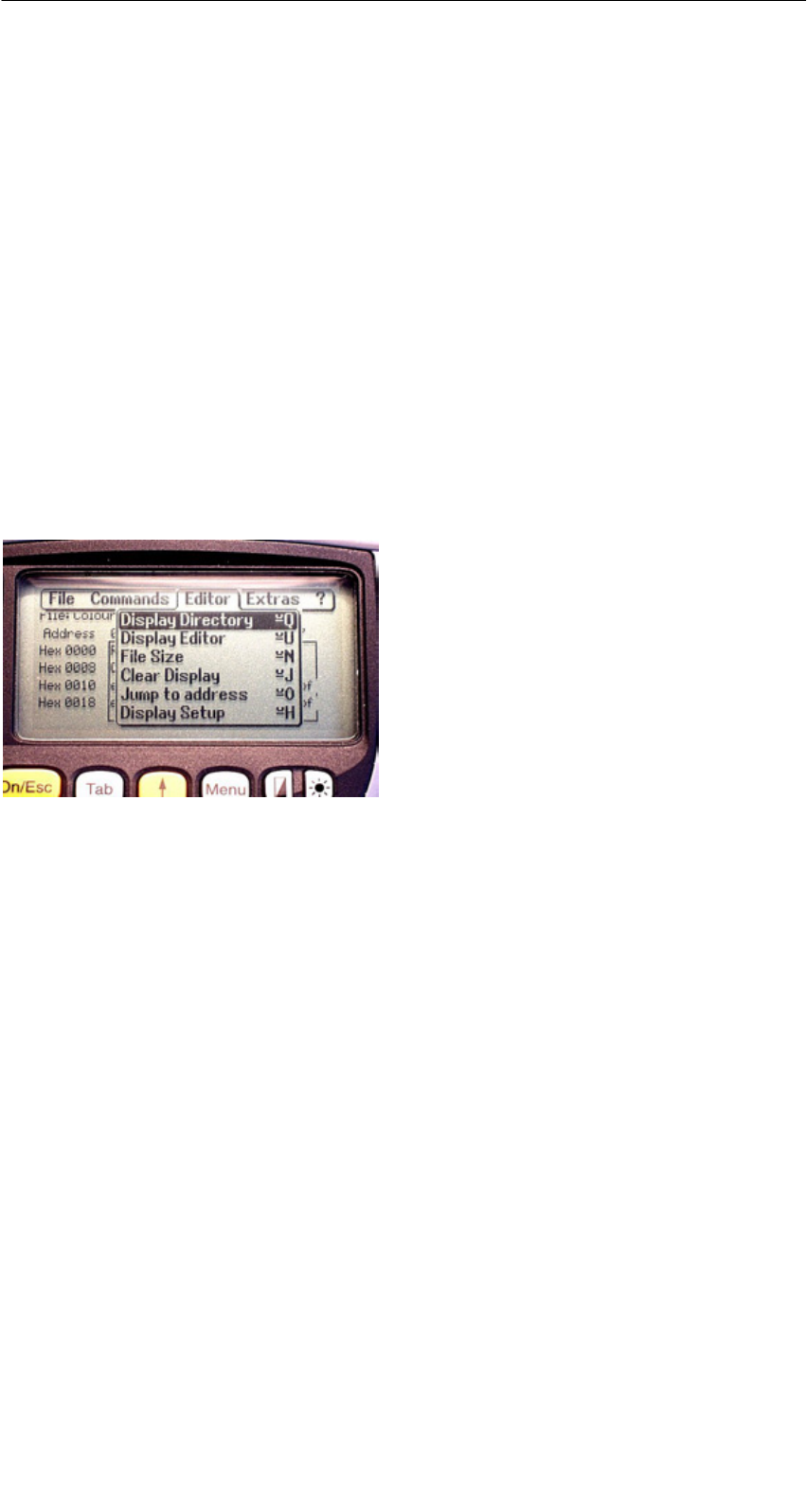
5.6 The Editor Functions
5.6.1 Display Directory
This function switches the display to the directory view (see chap. 5.3.2). The
directory which was read last is displayed. The directory can be from the MDS
or the hand-held terminal.
5.6.2 Display Editor
This function switches the display to the editor view (see chap. 5.3.1). The dis-
play shows the file which was read last. This file can be from the MDS or the
hand-held terminal.
The “FILEHANDLER” Program

R 01.04
E-49
STG Hand-Held Terminal
(5)J31069-D0126-U001-A5.1-7418
5.6.3 Change File Size (File Size)
The editor shows the current size of a file in the second line. This length can
be modified with the “File Size” command. When the file is made longer, an ap-
propriate number of zeros (00 Hex) is appended to the end of the file. The edi-
tor shows the appended portion with inverted digits.
5.6.4 Delete Display (Clear Display)
This function clears the memory of the editor display. The hexadecimal value
of the filler character can be specified. The standard filler character is 00hex.
After deletion, all data in the display are shown inverted to indicate that no data
have been entered yet by the user.
5.6.5 Jump to Address
Normally the cursor is positioned within a file with the four arrow keys (z, !, ",
#). With large files, it is much quicker to use the “jump to address” function to
position the cursor anywhere within the file. You can also call the “jump to ad-
dress” function very easily with the Tab key.
5.6.6 Display Setup
The display is set here. You can choose either hexadecimal or ASCII format.
In ASCII format, the characters which cannot be shown appear as white fields.
For more information, see the ASCII table in appendix A.3.
The “FILEHANDLER” Program
R 01.04
E-50 STG Hand-Held Terminal
(5)J31069-D0126-U001-A5.1-7418
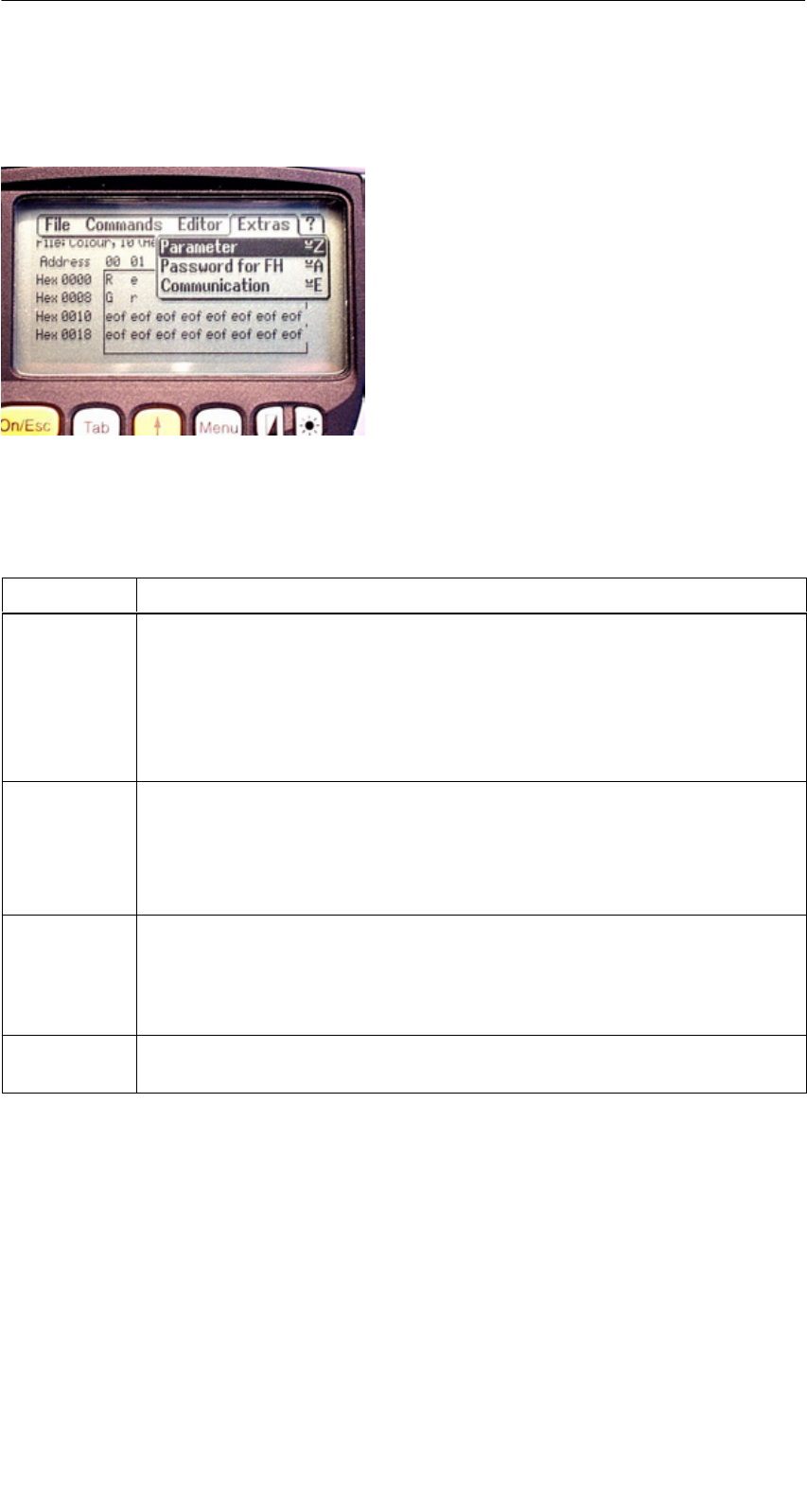
5.7 The Extras Functions
5.7.1 Parameter
The “parameter” function is used to make the basic settings for the filehandler.
Parameter Description
MDS size The gross memory size of the MDS is set here.
This memory size is shown in the first line of the display. The Format
command uses the memory size to specify the file system. If the
“MDS size” parameter does not correspond to the MDS being used,
the MDS can still be used. Only the Format command would produce
the wrong result.
MDS type Here you can switch between RAM, EEPROM and MDS 507. FRAM
memory is treated as RAM memory. If EEPROM is selected, the bat-
tery error message is suppressed on the display since these MDSs do
not have batteries. If MDS 507 is selected, the dialog battery is also
evaluated. When empty, this is shown on the display.
ECC
SLG no.
(hex)
Activate/deactivate ECC driver
When an MDS is processed, the SLG no. selected here is written to
the system area of the MDS. It has no effect on the function of the Fi-
lehandler program on the STG.
EAKO The entry/exit check cannot be set on the STG with the filehandler.
The STG does not use entry/exit control (AEKO = 4).
The “FILEHANDLER” Program

R 01.04
E-51
STG Hand-Held Terminal
(5)J31069-D0126-U001-A5.1-7418
5.7.2 Password for Filehandler (Password for FH)
The filehandler password protects the STG data on the MDS from being manip-
ulated by unauthorized parties. The passwords for the “Filehandler” and
“MOBY D/E/F/I/U” programs are identical. See chapter 4.5.2 for a description
of how to handle the password.
5.7.3 Communication
In principle, communication of the filehandler is always set to “read head.”
However, the filehandler can be changed to “ASM on RS 232” as an option. A
type “ASM420-RS232” module can then be connected to the hand-held termi-
nal. For more information, see chapter 6.6.
Remember that a type “ASM 421” module cannot be used with the STG.
5.8 The “?” Functions
These functions are the same as those of the “MOBY D/E/F/I/U” programs.
See chapter 4.6.
The “FILEHANDLER” Program

R 01.04
E-52 STG Hand-Held Terminal
(5)J31069-D0126-U001-A5.1-7418
6 Expanded Functions
6.1 Storing the MDS Data on the Hand-Held
Terminal
The data read from the MDS are automatically stored on the hand-held terminal
in a file named “READ_D.HEX,” “READ_E.HEX,” “READ_F.HEX,”
“READ_I.HEX” or “READ_U.HEX” on the “RAMDRIVE” drive of the PSION.
Every additional read command overwrites this file.
When the MDS is write-accessed, the write data are written from the editor to
the MDS and also to the “RAMDRIVE (M:)” drive of the PSION under the name
“WRITE_D.HEX,” “WRITE_E.HEX,” “WRITE_F.HEX,” “WRITE_I.HEX” or
“WRITE_U.HEX.” Every additional write command overwrites this file.
The “file/load file” function shows all files with the file extension “.HEX.” You
can select one of them with the cursor keys. This file is then loaded to the edi-
tor. There is no storage under the name READ_x.HEX or WRITE_x.HEX.
The “file/save” function stores the data of the editor in a file with the file exten-
sion “.HEX” and at the same time the ID number in a file with the file suffix
“.HX1” on the RAMDRIVE drive of the PSION (i.e., drive M:). You can specify
any name of 1 to 8 alphanumeric characters.
Note
When you read data from the MDS, modify data in the editor and
then save the data, the modified data will be stored in the .HEX file.
Expanded Functions
R 01.04
E-53
STG Hand-Held Terminal
(5)J31069-D0126-U001-A5.1-7418
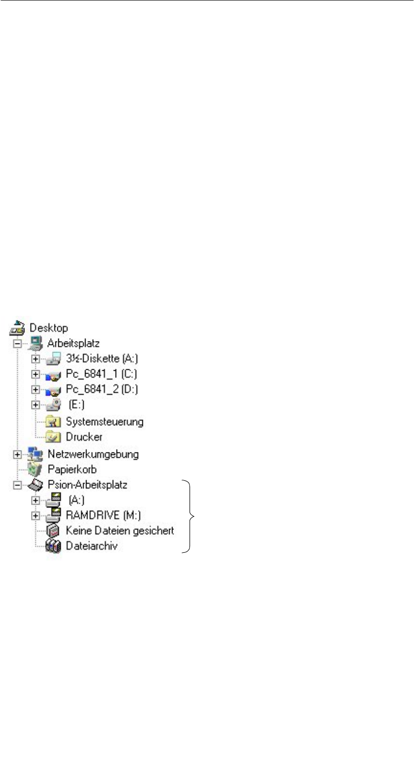
6.2 Copying MOBY Data from and to the Hand-
Held Terminal
6.2.1 What Is Needed in Addition?
SThe PsiWin program. This is a file manager available from PSION for the
PSION Workabout hand-held terminal.
SA 3link interface with the applicable cable for connecting the PC to the
PSION Workabout
These components can be ordered directly from PSION. See appendix A.1.
6.2.2 Using the PSION File Manager
The PSION file manager is installed in the Windows Explorer of your PC. This
provides your Explorer with additional drives. The following figure shows a
sample configuration. You will find it very easy to copy data and programs the
way you always have with Explorer.
The PSION desktop is set up in
Explorer when PsiWin is installed.
You will not be able to open the PSION desktop in Explorer until you connect
the PSION with the 3link cable and the wall holder, and enable the interface for
communication (i.e., port C).
Expanded Functions
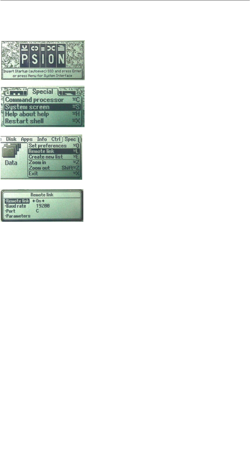
R 01.04
E-54 STG Hand-Held Terminal
(5)J31069-D0126-U001-A5.1-7418
How to enable port C:
SExit the STG program with EXIT. The basic
PSION menu appears.
SMenu key: Position the cursor on “System
screen,” and acknowledge with “Enter.” A user
interface similar to Windows appears.
SMake the following settings in this window.
Remote link = ON, baud rate = 19200,
port = C, parameters = (don’t specify anything).
SBefore you acknowledge with “Enter,” establish
a connection to the PC with the 3link cable
described in chapter 6.2.1. Otherwise you will
receive the message “Device does not exist.”
SMenu key: Call SPEC/REMOTE LINK. The
“Remote link” window appears.
If you made wrong entries during this procedure and are unable to continue,
perform a system RESET as described in chapter 6.7.
If the message “keine Verbindung” (i.e., no connection) continues to appear in
the PSION desktop directory of Explorer, check the 3link cable between the
hand-held terminal and the PC, and the REMOTE setting on the hand-held ter-
minal.
Open the file tree of the hand-held terminal by double-clicking the “RAMDRIVE”
drive. There you will find, among others, the “READ_D/E/F/I/U.HEX” file and
the files which you stored with the extension “.HEX.” Now drag and drop or
copy these files from the PSION drive to the PC drive.
Expanded Functions

R 01.04
E-55
STG Hand-Held Terminal
(5)J31069-D0126-U001-A5.1-7418
The length of the READ or WRITE file is the same as that of the MDS which
was read.
READ_D.HEX: 44 bytes for I-Code1
112 bytes for I-Code SLI
256 bytes for Tag-it HF-I
1000 bytes for my-d
READ_E.HEX: 768 bytes for MOBY E (in normal mode)
1024 bytes for MOBY E (after reading the raw data)
1024 bytes for MOBY E (in SIM mode)
READ_F.HEX: 5 bytes for MOBY F (after reading an F1xx MDS)
192 bytes for MOBY F (after reading an F4xx MDS)
256 bytes for MOBY F (after reading the raw data of an
F4xx MDS)
READ_I.HEX:
Setup Setting No ECC With ECC
62 bytes
128 bytes
2 KB
8 KB
32 KB
62
128
2045
8189
32765
42
112
1778
7154
28658
READ_U.HEX:
Setup Setting
2 KB
32 KB
2048
32768
The contents of the file can now be indicated and changed with an appropriate
editor on your PC.
When ASCII data were read from the MDS:
Any editor can be used (e.g., NOTEPAD, WRITE, WORD and so on).
When binary data were exchanged with the MDS:
Use a HEX editor. HEX editors are available on the shareware market
(e.g., Hedit and so on) or on the professional market (e.g., Codewright).
After concluding your session with PsiWin, the remote-link connection should
be disconnected again.
To restart the STG application, see chapter 6.7.
Before starting a new session with PsiWin, the STG application should be ex-
ited.
Expanded Functions

R 01.04
E-56 STG Hand-Held Terminal
(5)J31069-D0126-U001-A5.1-7418
6.2.3 Organization of the READ.HEX File
The READ_x.HEX file only contains the pure data which also exist on the MDS.
The length of the file is the same as that of the MDS, specified in bytes.
6.2.4 Organization of the READ.HX1 File
The READ_x.HX1 file contains the ID number. The READ_x.HX1 file is only
created for MOBY D/E/F/U.
6.3 Functions with the PSION Operating System
You can use the FILE/EXIT menu command to access the operating system
level of the hard-held terminal. We will now describe some of the functions
which are available with the PSION operating system.
SSimple writing of a batch file to copy MDS data to a memory card (e.g., on
drive B:).
SGeneration and modification of an AUTOEXEC file to change the time for au-
tomatic switch-off or the time for the backlight to save battery power and thus
increase operating time for one battery charge. The AUTOEXEC file is lo-
cated in directory A:\BTF\Autoexec.btf.
SEdit the read MOBY data with the PSION editor. Remember that this editor
can only be used when the MDS data are in ASCII format.
SSpread sheet function
SCalculator
SExecution of DOS commands
See the manual entitled “PSION Workabout USER GUIDE” for a detailed de-
scription of operating system functions and standard programs. This manual
can be ordered from PSION. See appendix A.1.
Expanded Functions

R 01.04
E-57
STG Hand-Held Terminal
(5)J31069-D0126-U001-A5.1-7418
6.4 Parallel Execution of Several Applications
Several applications can be processed at the same time on the Windows level
of the PSION hand-held terminal.
Proceed as shown below.
SExit the MOBY service and test program. The following basic PSION screen
appears.
SMenu → System screen
You are in the Windows level of the PSION. Several icons appear on the
display.
SMove the cursor to the right until the IMG application appears on the display.
SThe applications which you can start are shown under the IMG icon.
– MOBY D/E/F/I/U = MOBY service and test program for the particular
MOBY family
– FILEHAND = MOBY filehandler programm
– MENU = MOBY program selection menu
– Other customer applications. These must be stored in the IMG directory.
On delivery, no other application is indicated here.
SSelect the MOBY D/E/F/I/U application with the cursor keys, and press Enter.
The familiar MOBY STG application is started.
SPress the key combination “ + TAB.” The basic PSION screen reappears
on the display.
SSelect the next program to be started on the IMG icon or on the total Win-
dows screen (e.g., the CALC pocket calculator), and start it by pressing En-
ter. This program now appears on the monitor screen.
Expanded Functions
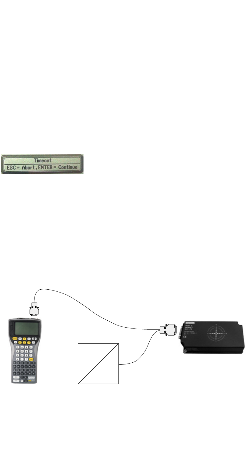
R 01.04
E-58 STG Hand-Held Terminal
(5)J31069-D0126-U001-A5.1-7418
This procedure can be used to start applications and PSION operating pro-
grams in addition to the normal MOBY application. All programs run simulta-
neously on the hand-held terminal.
6.5 Automatic Power Saver Function
The PSION hand-held terminal has an automatic power saver function. This is
activated after no keys have been pressed on the PSION for approximately
5 minutes.
In addition, the “MOBY D/E/F/I/U” programs have another power saver function.
The MDS command being executed is interrupted if no MDS is detected 30
seconds after the start of an MDS command or the MDS being processed is
moved out of the field for more than 30 seconds. The following message ap-
pears.
You can now completely terminate the command
with ESC or continue with ENTER. If you decide
to continue, the interrupted command is contin-
ued at the point at which it was interrupted.
6.6 Connecting SIM Devices (MOBY E/I/V)
A MOBY E SIM can be connected to the RS 232 interface of the PSION. The
following figure shows the connection diagram. Before commissioning, a
switch must be made to MOBY E/SIM or ASM 420/I/V with the “EXTRAS/COM-
MUNICATION/PROTOCOL” function.
With this configuration, SIM can be used to work with the “MOBY” program and
user applications with the MOBY library. Cf. appendix A.2.
MOBY E/SIM:
220 V AC
24 V DC
Cable (6GT2 391-1DH50)
and
Power pack (6GT2 090-0HB00)
Expanded Functions

R 01.04
E-59
STG Hand-Held Terminal
(5)J31069-D0126-U001-A5.1-7418
Note
Since the standard SIM uses cyclic operation, it takes much, much
longer to process a read/write command than with the STG read
head. The EXTRAS/MOBY E Setup/MODE command can be used
to switch the SIM to the faster read mode. This command must be
repeated each time SIM is turned on.
ASM 420/I/V:
This settings permits an ASM 420/RS 232 to be connected to the hand-held
terminal. The connection cable must comply with the specifications in the
ASM 420 documentation. In ASM 420 mode, the MOBY V driver is always en-
abled during the “MOBY I” program. SLG 65 can be used on the ASM 420 with
this. Use of MOBY I SLGs is limited.
Assignment of the RS 232 interface on the hand-held terminal:
Pin Designation
2 TxD
3 RxD
5 Gnd
6.7 System RESET
The hand-held terminal executes a system RESET when the device is turned
on for the first time after the batteries have been installed. This RESET is the
same as a hardware RESET.
A system RESET can also be triggered by hand. To do this, press the key +
Ctrl + Del (Shift + Esc + Del on the PSION with the numerical keyboard) simul-
taneously.
During the system RESET:
SThe MOBY STG application is started again.
SData stored in flash memory are always retained (drive A: or B:).
SThe data in RAM memory (drive “RAMDRIVE:”) are retained. However,
these data will be lost if all batteries (including lithium cell) of the PSION are
removed.
Expanded Functions

R 01.04
E-60 STG Hand-Held Terminal
(5)J31069-D0126-U001-A5.1-7418
7 The “MOBY D/E/F/I/U” Programs with the
PSION Numeric Model
The MOBY service and test program also functions without restrictions on the
PSION Workabout with numeric keyboard. This PSION model is useful for ap-
plications in which only simple and identical applications are performed by un-
trained personnel. This model of the hand-held terminal can be ordered di-
rectly from PSION. See appendix A.1.
The functionality of the 4 function keys can also be put to good use. The fol-
lowing STG functions can be called directly via function key.
F1 = Read MDS
F2 = Write MDS
F3 = Load data from file
F4 = Save data in file
Data can only be entered with the numeric keys.
The “MOBY D/E/F/I/U” Programs with the PSION Numeric Model

R 01.04
E-61
STG Hand-Held Terminal
(5)J31069-D0126-U001-A5.1-7418
8 Error Messages
What to do when ...
... The PSION display goes blank during MOBY read/write.
SThe batteries of the PSION are empty. Insert device in the charging shell,
or install new batteries.
SThe battery pack was installed incorrectly on the basic device. The catch
of the battery pack must be on the left side.
... The display remains blank after the device is turned on.
SThe batteries are empty.
SThe contrast of the display is not adjusted correctly. To adjust, use the
key in the top row.
... Error messages appear but they are not defined anywhere.
SRemove both batteries from the basic device. Wait 60 seconds, and re-
place them again. The device is now in its status on delivery. If the error
continues to occur, the device may be defective.
... LED for communication is red on the STG U hand-held terminal.
SThe battery of the MOBY U antenna is empty. → Charge battery (see
chap. 3.4).
... No communication between the basic device and the antenna (handshake
timeout) with the STG U hand-held terminal.
SThe battery of the MOBY U antenna is empty. → Charge battery (see
chap. 3.4).
SCheck the RS 232 interface on the basic device for secure plug connec-
tion.
... Operation time of the MOBY U antenna gets shorter and shorter.
SInstall a new battery in the MOBY U antenna.
Error Messages
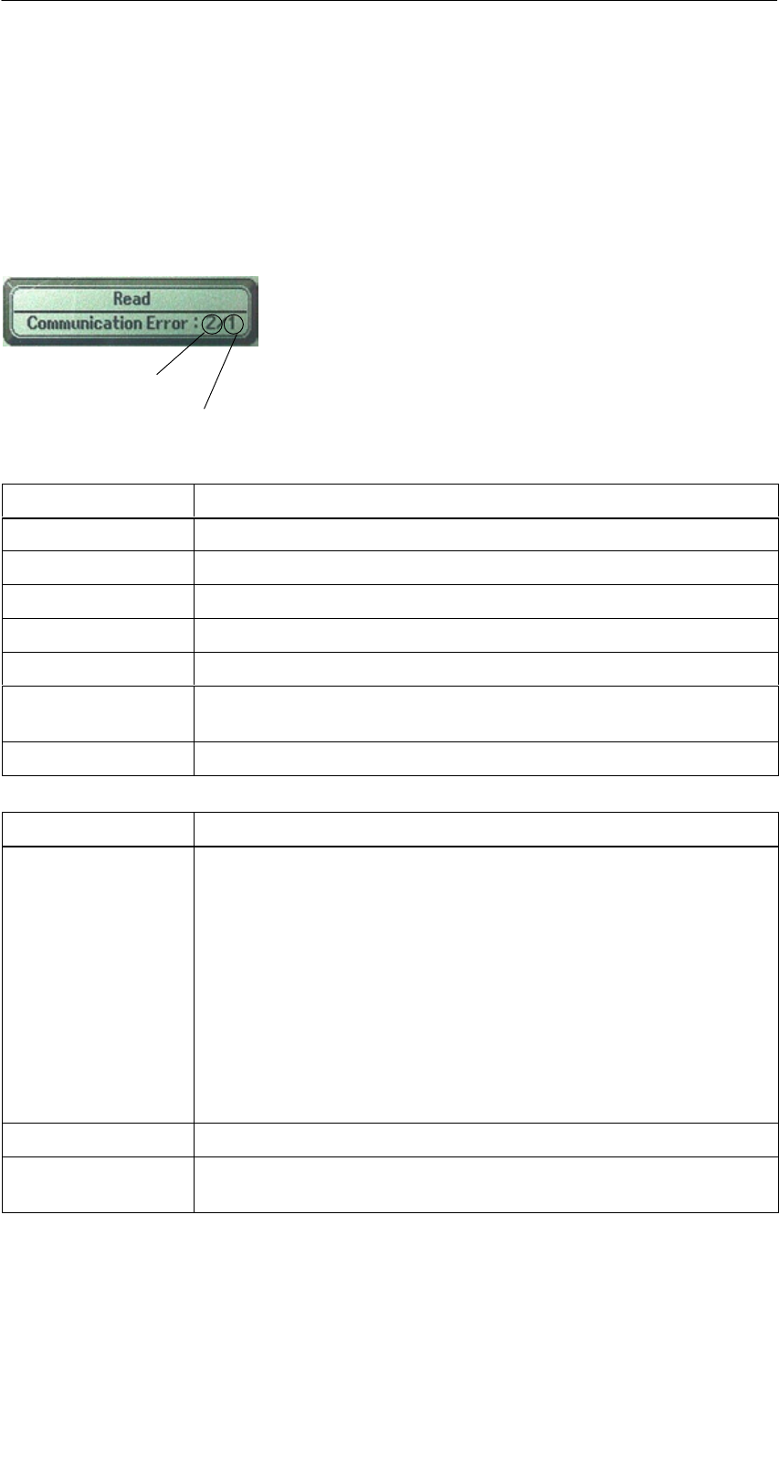
R 01.04
E-62 STG Hand-Held Terminal
(5)J31069-D0126-U001-A5.1-7418
8.1 Error Messages with the “MOBY D/E/F/I/U”
Programs
The messages in the following tables can occur during operation. The mes-
sages are indicated in a separate window. A message can have the following
format.
The message is coded in several digits, has the
format is xx/yy/zz, and is used for precise error
analysis. The following tables list the types of
errors and the error designations in detail. The
information in /zz is included in some messages.
“zz” contains additional error information (e.g.,
the block in which the error occurred).
Type of error
Exact error designation
Type of Error Description
1 to 2 General errors
3 to 9 MOBY E errors
10 to 15 MOBY F errors
20 Timer errors
30 to 37 MOBY I errors
42 to 45
52 to 57
MOBY D errors
MOBY D ISO errors
60 to 72 MOBY U errors
Error Designation Possible Causes and Their Correction
1, 2, 3, 4, 5, 6 SReader device fails to send start protocol.
SIs read head screwed on?
SDoes the read head match the protocol setting? (See
menu: Extras/COMMUNICATION.)
SBatteries in the reader device are dead. (The batteries may
be defective.)
SInternal program error
SThe date is not permitted for the “read MDS status” function.
(MOBY U: Error designation = 3 for error type = 64)
⇒Set date (see chap. 4.2.5).
7Interface defective
10, 11, 12 Reader device doesn’t answer at all or sends an incorrect an-
swer (MDS D1xx/MDS F4xx).
Error Messages

R 01.04
E-63
STG Hand-Held Terminal
(5)J31069-D0126-U001-A5.1-7418
Error Designation Possible Causes and Their Correction
20 SReader device doesn’t answer.
SCheck parameters in the Extras/COMMUNICATION menu.
With SIM mode, “Interface” and “Protocol” must both be set
to SIM.
SBatteries in the reader device are empty. (The batteries
may be defective.)
21 Reader device doesn’t answer at all or sends an incorrect
answer.
SInternal program error (MDS D1xx)
22 to 27 SReader device sends the wrong answer.
SMDS is not personalized with the MOBY key.
SInternal program error (MDS D1xx/MDS F4xx)
32 Illegal request, internal program error
SCheck contact to read head.
SRead device doesn’t answer (MDS E6xx)
33, 34, 35, 36 Internal program error
SExit STG program, and start again.
SRead/write error (MDS F4xx)
37 SRead head gives you an error message.
SRead head is faulty.
SCRC error of MDS. Communication error to MDS. MDS is
located on the boundary.
SMDS has a defect.
SInternal program error
38 Specified block is write-protected.
39 Several MDSs are in the field.
SInternal program error (MDS D1xx)
40, 41, 42 Reader device doesn’t answer at all or sends an incorrect an-
swer (MDS D1xx/MDS F1xx/MDS Uxxx).
SInternal program error (MDS D1xx)
SCheck interface to MOBY U antenna (MDS Uxxx).
43 User termination with ESC
45 Wrong answer from read device
50 Error while reading or writing the MDS data
52, 53, 54, 55,
56, 57
Internal program error on MOBY read head
63 Authentication error. The MDS doesn’t have the MOBY key.
STry setting the “B” key under “Extras/MOBY E Setup.”
Error Messages

R 01.04
E-64 STG Hand-Held Terminal
(5)J31069-D0126-U001-A5.1-7418
Error Designation Possible Causes and Their Correction
65 Interface error. Appears when a SIM is connected.
SCheck parameters in the “Extras/COMMUNICATION”
menu.
SCheck plug and cable to SIM.
66 General read/write error on MOBY read head
67 Internal program error on MOBY read head
70 SWrite not successful
SSeveral tags in the field
80 MDS type on reader device is not supported.
81, 82 SRead device sends wrong answer.
SMDS not personalized with MOBY key
SInternal program error (MDS Fxxx)
101 to 132 Read device sent error (MOBY I/U).
Specification of certain errors:
101 Presence error
SNo MDS in the field which has the MDS ID number con-
tained in the command.
103 Error in the connection to the SLG
SRead head hardware has a defect.
104 Error in MDS memory
SExecute INIT command. Before executing this command,
make sure that the memory size of the MDS is set correctly
under “Extras/MOBY I Setup.”
SThe MDS is defective.
105 MOBY command cannot be interpreted by the read head/
MOBY U antenna.
SCheck the memory size under “Extras/MOBY I Setup” or
“Extras/MOBY U Setup.”
106 SField interference on read head. External interference.
SThe MDS left the field during communication.
SField interference during communication
107 Too many sending errors. The MDS wasn’t able to correctly
receive the data from the read head.
SThe MDS is located in the boundary area of the read head.
109 CRC error due to field interference while initializing the MDS
110 MDS cannot be initialized and is defective.
Error Messages

R 01.04
E-65
STG Hand-Held Terminal
(5)J31069-D0126-U001-A5.1-7418
Error Designation Possible Causes and Their Correction
111 Timeout during initialization (MOBY I)
SThe MDS is located in the boundary area of the read head.
SAn MDS 507 is initialized but MDS 507 mode has not been
enabled under “Extras/MOBY I Setup.”
The MDS memory cannot be read correctly (MOBY U).
112 SThe MDS memory cannot be written and is defective.
SThe OTP memory cannot be written again.
113 The address area of the MDS was exceeded.
SCheck the memory size under “Extras/MOBY I Setup” or
“Extras/MOBY U Setup.”
114 ECC error or MDS not initialized in ECC mode
SEnable ECC mode under “Extras/MOBY I Setup,” and then
execute the INIT command.
115 Reset message after return of power
SThe hand-held terminal has a defect in the power supply to
the read head. (Try charging/replacing the batteries.)
SThe hardware of the read head has a defect.
125 Internal program error. Previous command is active.
129 The number of MDSs in the field is not permitted. Number of
MDS > multitag in the “SLG Status” function under “Extras.”
130 Internal program error. The telegram layout of the command to
the read head is wrong.
180 to 243 Internal program error (MDS D1xx)
Turn the device off and on again. If error continues to occur,
contact Customer Support and specify the error number.
251 Read/write comparison not successful
255 No card/no MDS in the field
Error Messages
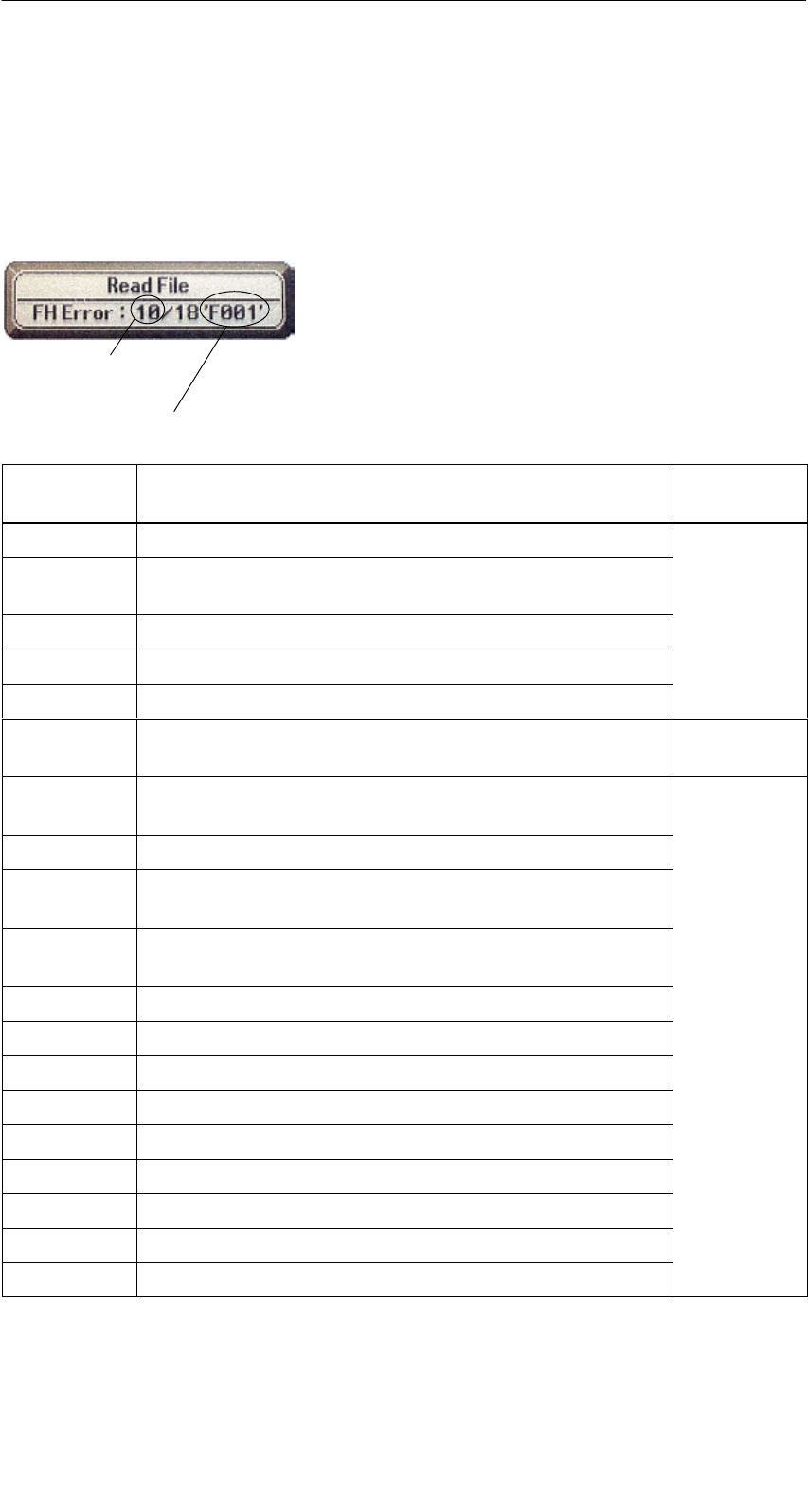
R 01.04
E-66 STG Hand-Held Terminal
(5)J31069-D0126-U001-A5.1-7418
8.2 Error Messages with the “FILEHANDLER”
Program
The following table lists the messages which can occur with the filehandler. A
filehandler error message looks like this.
The filehandler error is shown in the same way
as the filehandler on the SIMATIC. The error
message has one alpha character followed by a
3-position number. Most of the error codes are
identical with the error numbers of all MOBY file-
handler interfaces.
Type of error
(see chap. 8.1)
Exact filehandler error
Filehandler
Error
Description of Error, Its Cause and Correction Type of
Error
A006 Unknown command. Command identifier KK is illegal.
A011 With 1st command block: DBN not 1
With next block: KK or DBN incorrect
Protocol
A015 Checkbyte error while receiving from S5
Protocol
errors
A016 Command from other sender is being processed.
A020 Wrong number of characters in the telegram
B001 Error in the connection to the SLG
Read head defective
SLG errors
C002 Error on RAM of the MDS. Replace MDS and perform
FORMAT.
C006 Presence error. MDS in boundary area.
C007 Parameterization error during FORMAT. Command
cannot be interpreted.
C008 Too many sync attempts. Field interference on read
head.
C009 Too many sending errors
C010 CRC sending error MDS errors
C011 FORMAT. CRC error while receiving.
C012 FORMAT. MDS cannot be initialized.
C013 FORMAT, timeout. MDS in boundary area.
C014 FORMAT, not initialized. Check Extras/Parameter.
C015 CMD address error. Check Extras/Parameter.
C016 ECC error. Format MDS again. Disable ECC mode.
C017 General driver error
Error Messages

R 01.04
E-67
STG Hand-Held Terminal
(5)J31069-D0126-U001-A5.1-7418
Filehandler
Error
Type of
Error
Description of Error, Its Cause and Correction
D001 Only RESET command permitted
D005 Illegal parameters for FORMAT, CREATE, WRITE,
UPDATE or ATTRIB
D009 RESET command parameter wrong
D014 CREATE and WRITE: The user data area of the MDS
is completely full. Job-related
D015 Only FORMAT command possible. MDS not identified.
Job related
errors
D018 Start address in the command is outside the data area
(i.e., start address > file length).
D022 Directory and/or FAT. Modifying an MDS protected with
COVER is illegal.
D023 COVER: MDS name wrong
E001 MDS type is wrong or doesn’t match the set mode
(ECC).
E002 CREATE command: No more directory entries free Directory-
related
E003 CREATE command: File already exists in the directory. re
l
ate
d
errors
E005 READ or WRITE: A FAT block sequence error was de-
termined. The FAT is defective.
errors
F001 The addressed file does not exist.
File related
F005 WRITE/UPDATE/DELETE command for a file which is
protected with the appropriate attribute
File-related
errors
H140 Serial interface error
H141 Wrong interface
H142 Faulty timer
H143 Interface error
H144 Start-protocol error
H145 Reset error, WRITE Error
H146 Reset error, READ, no STX
Error
messages
of the
H147 Reset error, READ, timeout of the
filehandler
H148 Reset error, READ, wrong response
filehandler
application
H149 Start error, WRITE
pp
H150 Start error, READ, no STX
H151 Start error, READ, timeout
H152 Start error, READ, wrong response
H153 Start error, WRITE, length too long
Error Messages

R 01.04
E-68 STG Hand-Held Terminal
(5)J31069-D0126-U001-A5.1-7418
9 Technical Data
Hardware
Processor NEC V30mx, 27.68 MHz, 80C86-compatible
RAM memory 2 Mbytes of which approx. 1.8 Mbytes can be used as desired
ROM memory 2 Mbytes for operating system
User program 1 MB (with MOBY service and test program)
Monitor screen Graphic LCD monitor screen with 240 x 100 pixels, gray-stage
scale, backlighting can be turned on
Keyboard Alphanumeric with 57 keys
Sound Piezo signal encoder
Power supply NiCd battery pack with 2 type-AA cells (1 Ah)
High-speed chargeable, automatic switch-off
Operation time: 20 hours
(Read head inactive, display not lighted)
4.5 hours 1
(Read head active, display not lighted)
10 hours
(Read head inactive, display lighted)
Backup battery: 3 V lithium cell (CR 1620)
Interfaces LIF interface (LIF = Low Insertion Force) for battery charging
and communication with PC and printer (3link cable not in-
cluded)
RS 232 and TTL interface for connection of a MOBY read
head
RS 232 interface for connection of a MOBY U antenna
Security Locking mechanism for battery and program memory
Software
Operating system EPOC/16 multitasking, graphics support, GUI interface, Inter-
preter similar to MS-DOS
File management MS-DOS-compatible
Integrated
software
MOBY service and test program, spread sheet calculation,
data base, pocket calculator, communication
1 Does not apply to MOBY U since the antenna has its own battery. For operation time (antenna
active), see technical data of MOBY U antenna.
Technical Data

R 01.04
E-69
STG Hand-Held Terminal
(5)J31069-D0126-U001-A5.1-7418
Technical Data Complete Device
(incl. Batteries)
Read Head
Dimensions 90 x 260 x 35 [mm]
(MOBY D/E/F/I)
90 x 64 x 35 [mm]
(MOBY D/E/F/I)
282 x 235 x 93 [mm] (MOBY U)
Weight Approx. 480 g
(MOBY D/E/F/I)
Approx. 100 g
(MOBY D/E/F/I)
Approx. 1450 g (MOBY U) Approx. 1100 g (MOBY U)
Temperature Operation: –20 °C to +60 °C
Storage: –25 °C to +70 °C (without batteries)
Relative humidity 0% to 90%, no condensation
Protection rating IP54 (protected against splashed water) 2
Shock resistance Max. falling height on concrete: 1 m (MOBY D/E/F/I)
0.5 m (MOBY U)
EMC EN 55022
Electrostatic, RF,
EFT
IEC 801-2; IEC 801-3; IEC 801-4
2 With STG U hand-held terminal, only for complete device with PSION Workabout
Technical Data

R 01.04
E-70 STG Hand-Held Terminal
(5)J31069-D0126-U001-A5.1-7418
RF read/write head
MOBY D 13.56 MHz (I-Code; Tag-it)
Max. read distance: 60mm with MDS D139
25mm with MDS D160
Labels based on I-Code in standard size
(approx. 85 x 55 mm):
Max. read distance: 75mm with I-Code1
100mm with I-Code SLI
100mm with Tag-it HF-I
100mm with my-d
Certifications: ETS 300 330
MOBY E 13.56 MHz (MIFARE)
Max. read distance: 30mm with MDS E611
18mm with MDS E600
8mm with MDS E624
4mm with MDS E623
3mm with MDS E623,
mounted in metal
Certifications: ETS 300 330 reg. no. G100213L
FCC ID: KR5MIS
MOBY F 125 kHz (HITAG)
Max. read distance: 80mm with MDS F125
50mm with MDS F415
60mm with MDS F124
Certifications: ETS 300 330 reg. no. G100294L IF
MOBY I 1.81 MHz (data); 134 kHz (power)
MDS Type Max. Read Distance
(in mm)
401/402
404/514/413E
403
506
439E
507 with battery
507 without battery
6
20
8
12
12
35
4
Certifications: ETS 300 330 reg. no. TTI-P-G 128/96
FCC ID: KR5MIS-I
Technical Data

R 01.04
E-71
STG Hand-Held Terminal
(5)J31069-D0126-U001-A5.1-7418
MOBY U antenna
Transmission frequency 2.4 to 2.4835 GHz
Band width 2 x 1 MHz within 83 MHz
Gross bit rate of radio channel 384 kbit/sec
Data rate (read/write), net Approx. 8/4.8 Kbyte/sec without bunch
Antenna
SEmission direction
SAngle of opening
SPolarization
SEmission capacity
SEmission density
Vertical to back of MOBY U antenna
Approx. 90° (cone-shaped antenna field)
Circular
< 50 mV/m at 3-m distance
< 0.5 µW/cm2 at distance of 1 m
Range (read/write)
SLimit distance (Sg)
SMax./min./standard
SSite resolution
0.15 m to 3 m
Corresponds to set range limitation
3 m / 0.5 m / 1 m
Can be set over range limitation in increments
of 0.5 m
MDS acquisition time Approx. 3 sec with 1 MDS
(after communication button is pressed)
Power supply Lithium ion battery pack 2SIP CGR18650 HG
7.2 V 1.8 Ah
Rapid-charge capability, automatic switchoff,
lifespan: approx. 500 charging cycles
Current consumption (antenna on) < 800 mA
Operation duration 3> 2 months (antenna not active)
2 hours (antenna active)
The antenna is turned on via the communica-
tion button only for communication and then
automatically switched off again after the func-
tion is executed. The shortest switchon time for
communication is approx. 3 sec (depending on
the data volume) when an MDS is located in
the field.
Operating modes
SOff
SSearch
SCommunication
Antenna off
Ready to receive and evaluate search informa-
tion sent by the MDS
Communication with the MDS: read, write or
initialize
Minimum distance to an SLG U92
or another STG U ≥ (set range + 0.5 m)
Technical Data

R 01.04
E-72 STG Hand-Held Terminal
(5)J31069-D0126-U001-A5.1-7418
Serial interface to PSION
STransmission speed
STransmission protocol
RS 232
115.2 kBaud
3964R
Interface for battery charging
SVoltage/current
SCharge duration
4-pin socket for connection of the STG U
power pack
12 V DC/1.225 A
> 1.5 h
(lithium ion battery pack 2SIP CGR18650 HG)
Operator control elements Communication button
(for triggering communication)
Indication elements
SLED for charging the batteries
–On
– Not on
2 LEDs
Power pack connected
Red: Device is defective.
Yellow: Batteries are being charged.
Green: Batteries are charged.
Power pack not connected.
SLED for communication
– On
– Not on
Communication button pressed and communi-
cation not concluded
Red: Battery capacity is not sufficient for
communication.
Yellow: Antenna is activated. Ready to
identify an MDS or identify an MDS
and communicate with it
Communication concluded or not started
Housing
SColor/material Black/polyamide 6 GF 30
Certifications RF: I-ETS 330440+C1:1997
SAR: 99/519/EG
Safety: EN 60950:2000
EMC: EN 301489-01:2000
EN 301489-03:2000
ENV 50204:1995
FCC ID: NXWMOBYU-STGU
Safe for pacemakers
3 The operation time corresponds to the amount of time the antenna is on. For each MDS
function, this means the time from activation of the communication button to conclusion or
termination of the selected MDS function. If you do not point the hand-held terminal towards
an MDS after you press the communication button, the function is terminated after
30 seconds. The antenna is on during this time.
Technical Data

R 01.04
E-73
STG Hand-Held Terminal
(5)J31069-D0126-U001-A5.1-7418
STG U power pack With cable switch (on charging cable) and
charging adapter for PSION Workabout
Input voltage range 90 V to 264 V AC
Frequency range of the input volt-
age
47 Hz to 63 Hz
Nominal input current 400 mA
Nominal output voltage 12 V DC
Nominal output current 1.25 A
Basic load None
Short-circuit proof Yes
Potential isolation, primary/secon-
dary
3 kV AC
Dimensions, power pack
(L x W x H in mm) 87.5 x 51.5 x 34 (without connection plug)
Color/material Black/plastic (PPE-V1)
Ambient temperature
SOperation
STransportation and storage
0 °C to +40 °C
–40 °C to +70 °C
Relative humidity 0% to 90%, no condensation
Protection rating in acc. w.
DIN EN 60529 IP40
Weight, approx. 250 g
Charging cable 2 x 0.5 mm2 / 2 m long
Primary plug connector Can be changed
EU, UK, USA and ROW plug connector
(EU plug connector included)
Certifications 220 V to 240 V (Europe): CE
120 V (Canada and USA): cULus
Safety: EN 60950
EMC: EN 55011,
EN 55014 and
EN 55022 Class B
Technical Data

R 01.04
E-74 STG Hand-Held Terminal
(5)J31069-D0126-U001-A5.1-7418
A Appendix
A.1 Ordering Components for Expanded
Functions
The expanded functions of the MOBY STG hand-held terminal require compo-
nents which are not available from Siemens A&D SE.
If you need these components for your MOBY application, please contact
PSION directly or its representative in your country. You will find addresses
and order lists from PSION on the Internet under www.psionteklogix.com.
The PSION representative in your country is also located under this Internet
address.
The following components are required for the STG application as options.
Ordering Designation Remarks
3link interface for wall and vehicle holder
Dual AT/XT connection cable for the PC
PsiWin software
(for Win95/Win98/NT/2000)
Also available free of charge under
the PSION Internet address
User’s guide for PSION Workabout Ask your PSION representative.
Additional Components required for writing your own applications
C development package for Workabout
(SIBO C SDK)
Standard or professional available,
incl. Top Speed C compiler
Manual for C development package
Ask PSION or its representative directly for information on the following PSION
components.
SOVAL programming environment
SMemory expansion
SHigh-speed charging devices
SPSION Workabout with numeric keyboard
These components are not required for the STG application. They are only of
importance if you want to program your own identification application on the
hand-held terminal.
A
ppendix

R 01.04
E-75
STG Hand-Held Terminal
(5)J31069-D0126-U001-A5.1-7418
A.2 Developing User Applications
What Do I Need?
The C development package from PSION (SIBO C SDK incl. Top Speed Com-
piler) is required for user applications.
For the communication connection, you will also need a 3link interface and the
PC cable with a 9-pin sub D and mini DIN plug connector.
Although, in principle, applications can also be developed with the Basic
programming language OVAL, the MOBY library cannot be used.
The MOBY Library
A library for MOBY D, MOBY E, MOBY F, MOBY I and MOBY U is available.
The library (MOBY D/E/F/I/U) must be ordered under order number
6GT2 381-1AB00. The C library also includes a description of the interface
commands.
The following table summarizes the implemented commands.
The MOBY D Library
Function Call Short Description
RF_ReadBlock Reads a block from the MDS
RF_WriteBlock Writes a block
RF_ReadTagId Selects the tag. Reads the TagId
RF_Status Determines the tag type
RF_Init Writes all user blocks
nMobyDOpen Opens an interface
vMobyDClose Closes the opened interface
A
ppendix

R 01.04
E-76 STG Hand-Held Terminal
(5)J31069-D0126-U001-A5.1-7418
The tables below provide a summary of implemented commands.
The MOBY E Library
Function Call Short Description Type of Command
CCT_READ_N_BLOCK Read card data (1 to n data
blocks, max. of 96 bytes)
Standard
CCT_WRITE_N_BLOCK Write card data (1 to n data
blocks, max. of 96 bytes)
Standard
CCT_WRITE_SIGNAL Address digital output, re-
served for switching the
antenna
Standard
CCT_OFF Turn off antenna field Standard
CCT_MODE Set field mode of the
antenna field
Standard
CCT_OPEN Open logical device Only for
SIM operation
via RS 232
CCT_CLOSE Close logical device Only for
SIM operation
via RS 232
CCT_SETKEY Parameterize read-card/
write-card interface
Optional
CCT_SET_KEY_TEMP Change temporary key Optional
CCT_GET_FIELD_STATE Scan current card indices Optional
CCT_RESET Reset read head Optional -
general command
Although the commands of the MOBY E library are the same as those of the
standard MOBY E library “CCTWAPI,” not all commands of “CCTWAPI” are
available on the hand-held terminal.
A
ppendix

R 01.04
E-77
STG Hand-Held Terminal
(5)J31069-D0126-U001-A5.1-7418
The MOBY F Library
Function Call Short Description
proloc_ReadBlock Reads a block from the MDS (16 bytes)
proloc_ReadPage Reads a page from the MDS (4 bytes)
proloc_WriteBlock Writes a block to the MDS (16 bytes)
proloc_WritePage Writes a page to the MDS (4 bytes)
proloc_GetSnr Reads the TagId from the MDS
nGetTagType Determines the type of MDS in the antenna field
nMobyFOpen Opens a serial interface in PSION
vMobyFClose Closes the opened interface
The MOBY I Library (normal addressing of MDS)
Function Call Short Description
moby_init Initializes an MDS with a filler character from ad-
dress 0 to the end address
moby_read Reads a data block from the MDS
moby_write Writes a data block to the MDS
moby_reset Sends a reset command with parameterization
to the read head
moby_status Sends a status command to the read head
nMobyIOpen Opens the interface and turns on the read head
vMobyIClose Closes the opened interface. The read head is
turned off.
nMobyIReadStartProtocol Reads the startup telegram from the read head
A
ppendix

R 01.04
E-78 STG Hand-Held Terminal
(5)J31069-D0126-U001-A5.1-7418
The MOBY I Library (filehandler addressing)
Function Call Short Description
wFhRead Reads a complete file from the MDS
wFhWrite Writes a file or appends data to a file
wFhMdsStatus Sends a status command to the MDS
wFhAttrib Sets a file attribute
wFhDelete Deletes a file from the MDS
wFhCreate Sets up a new file on the MDS
wFhFormat Formats an MDS
wFhDir Reads a directory from the MDS
wFhCover Protects the MDS file structure
wFhDirInfo Writes information from the “DIR” structure to the
“DirInfo” structure
nTagTypeFromTable Returns the MDS type from a table
lTagLenFromTable Returns the MDS size from a table
Fhreset Resets the filehandler
nFhOpenCom Opens the interface and turns on the read head
vFhCloseCom Closes the opened interface. The read head is
turned off.
A
ppendix

R 01.04
E-79
STG Hand-Held Terminal
(5)J31069-D0126-U001-A5.1-7418
The MOBY U Library (normal addressing of MDS)
Function Call Short Description
moby_u_init Initializes an MDS with a filler from address 0 to
the end address
moby_u_read Reads one data block from the MDS
moby_u_write Writes one data block to the MDS
moby_u_reset Transfers reset command with parameterization
to the antenna
moby_u_mds_status Reads the status data from the MDS (e.g., the
battery lifespan)
moby_u_slg_status Sends status command to the antenna
nMobyUOpen Opens interface. Turns on antenna.
vMobyUClose Closes the opened interface. The antenna is tur-
ned off.
nMobyUReadStartProtocol Reads the startup telegram from the antenna
moby_u_CheckDSR Checks the DSR signal on the interface
moby_u_SetDTR Sets the DTR signal or resets it
moby_u_ReadOTP Reads the complete OTP memory
moby_u_WriteOTP Writes the complete OTP memory
moby_u_ReadTagId Reads the TagId from the MDS
A
ppendix
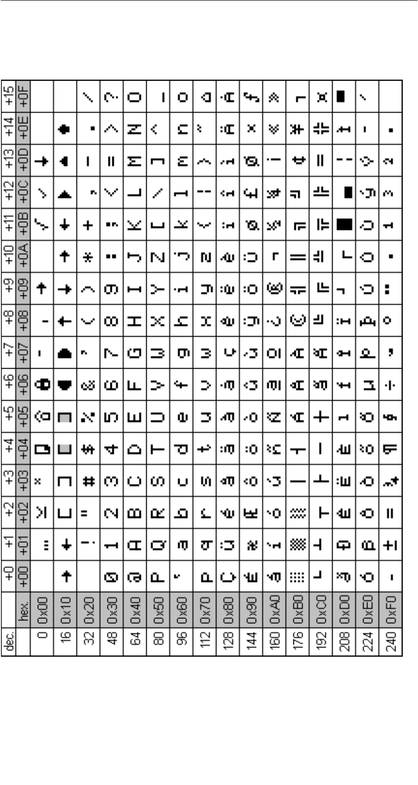
R 01.04
E-80 STG Hand-Held Terminal
(5)J31069-D0126-U001-A5.1-7418
A.3 ASCII Table
A
ppendix
TO:
Siemens AG
A&D SE EWF MS
PO Box 2355
D-90713 Fuerth
FROM:
Yourname: __________________________
Yourtitle: __________________________
Yourcompany:_ _________________________
Street: __________________________
City: __________________________
Telephone: _________________________
Please tick your branch.
-Automotive industry
-Chemical industry
-Electrical industry
-Foodstuffs
-Process control technology
-Mechanical engineering
-Petrochemistry
-Pharmaceutics industry
-Plastics processing
-Paper industry
-Textiles industry
-Transportation industry
-Other _____________

If you encountered concrete problems, please use this space to explain.
_____________________________________
_____________________________________
_____________________________________
_____________________________________
_____________________________________
_____________________________________
_____________________________________
_____________________________________
_____________________________________
_____________________________________
_____________________________________
_____________________________________
Remarks/Suggestions
Your remarks and suggestions help us to improve the quality of our documenta-
tion. Please complete this questionnaire as soon as you have time, and return it
to Siemens.
Title of your manual:_______________________
Order number of your manual:_ __________________
Please enter your personal evaluation from 1 (good) to 5 (poor).
1. Do the contents of this manual meet your requirements ?
2. Is it easy to find the information you need ?
3. Is the information written in an easy-to-understand manner ?
4. Does the amount of technical detail meet your requirements ?
5. What is your opinion of the figures and tables ?

Inhaltsverzeichnis
Allgemeines 1
Die Inbetriebnahme des STG 2
Die Bedienung des STG 3
Die Programme
“MOBY D/E/F/I/U” 4
Das Programm
“FILEHANDLER” 5
Erweiterte Funktionen 6
Die Programme
“MOBY D/E/F/I/U” mit
numerischer PSION-Version 7
Fehlermeldungen 8
Technische Daten 9
Anhang A
erschienen im Januar 2004
(5)J31069-D0126-U001-A5.1-7418
Bedienungsanleitung
MOBY
Handterminal STG

Sicherheitstechnische Hinweise
Dieses Handbuch enthält Hinweise, die Sie zu Ihrer persönlichen Sicherheit so-
wie zur Vermeidung von Sachschäden beachten müssen. Die Hinweise sind
durch ein Warndreieck hervorgehoben und je nach Gefährdungsgrad folgender-
maßen dargestellt:
Hinweis
ist eine wichtige Information über das Produkt, die Handhabung des Pro-
duktes oder den jeweiligen Teil der Dokumentation, auf den besonders
aufmerksam gemacht werden soll.
Qualifiziertes Personal
Inbetriebsetzung und Betrieb eines Gerätes dürfen nur von qualifiziertem Per-
sonal vorgenommen werden. Qualifiziertes Personal im Sinne der sicherheits-
technischen Hinweise dieses Handbuchs sind Personen, die die Berechtigung
haben, Geräte, Systeme und Stromkreise gemäß den Standards der Sicher-
heitstechnik in Betrieb zu nehmen, zu erden und zu kennzeichnen.
Bestimmungsgemäßer Gebrauch
Beachten Sie Folgendes:
!Warnung
Das Gerät darf nur für die im Katalog und in der technischen Beschrei-
bung vorgesehenen Einsatzfälle und nur in Verbindung mit von Siemens
empfohlenen bzw. zugelassenen Fremdgeräten und -komponenten ver-
wendet werden.
Der einwandfreie und sichere Betrieb des Produktes setzt sachgemäßen
Transport, sachgemäße Lagerung, Aufstellung und Montage sowie sorg-
fältige Bedienung und Instandhaltung voraus.
Marken
MOBYR ist eine Marke der SIEMENS AG.
Die übrigen Bezeichnungen in dieser Schrift können Marken sein, deren Benut-
zung durch Dritte für deren Zwecke die Rechte der Inhaber verletzen können.
Wir haben den Inhalt der Druckschrift auf Überein-
stimmung mit der beschriebenen Hard-und Software
geprüft. Dennoch können Abweichungen nicht aus-
geschlossen werden, so dass wir für die vollständige
Übereinstimmung keine Gewähr übernehmen. Die
Angaben in dieser Druckschrift werden regelmäßig
überprüft, und notwendige Korrekturen sind in den
nachfolgenden Auflagen enthalten. Für Verbesse-
rungsvorschläge sind wir dankbar.
HaftungsausschlussCopyright ESiemens AG 1999 All rights reserved
Weitergabe sowie Vervielfältigung dieser Unterlage,
Verwertung und Mitteilung ihres Inhalts ist nicht
gestattet, soweit nicht ausdrücklich zugestanden.
Zuwiderhandlungen verpflichten zu Schadenersatz.
Alle Rechte vorbehalten, insbesondere für den Fall
der Patenterteilung oder GM-Eintragung.
Siemens AG
Bereich Automation and Drives
Geschäftsgebiet Special Products,
Projects Automotive Industry,
Training
Postfach 4848, D-90327 Nürnberg E Siemens AG 1999, 2000, 2002, 2003, 2004
Technische Änderungen bleiben vorbehalten.
Siemens Aktiengesellschaft Bestell-Nr. (5)J31069-D0126-U001-A5.1-7418

A 01.04
D-I
Handterminal STG
(5)J31069-D0126-U001-A5.1-7418
Inhaltsverzeichnis
1 Allgemeines D-1. . . . . . . . . . . . . . . . . . . . . . . . . . . . . . . . . . . . . . . . . . . . . . . .
1.1 Einsatzgebiete D-1. . . . . . . . . . . . . . . . . . . . . . . . . . . . . . . . . . . . . . . .
1.2 Produktbeschreibung D-1. . . . . . . . . . . . . . . . . . . . . . . . . . . . . . . . . .
2 Die Inbetriebnahme des STG D-4. . . . . . . . . . . . . . . . . . . . . . . . . . . . . . . . .
2.1 Mitgelieferte Komponenten D-4. . . . . . . . . . . . . . . . . . . . . . . . . . . . .
2.2 Der Zusammenbau D-5. . . . . . . . . . . . . . . . . . . . . . . . . . . . . . . . . . . .
2.3 Einschalten des Gerätes und Einstellen der Betriebsart D-6. . . .
2.4 MOBY-Applikationen D-7. . . . . . . . . . . . . . . . . . . . . . . . . . . . . . . . . . .
2.5 Bedienung D-7. . . . . . . . . . . . . . . . . . . . . . . . . . . . . . . . . . . . . . . . . . . .
3 Die Bedienung des STG D-8. . . . . . . . . . . . . . . . . . . . . . . . . . . . . . . . . . . . .
3.1 Die Tastatur D-8. . . . . . . . . . . . . . . . . . . . . . . . . . . . . . . . . . . . . . . . . .
3.2 Die Antenne am Lesekopf und das Antennenfeld D-9. . . . . . . . . .
3.2.1 MOBY D/E/F/I D-9. . . . . . . . . . . . . . . . . . . . . . . . . . . . . . . . . . . . . . . . .
3.2.2 MOBY U D-11. . . . . . . . . . . . . . . . . . . . . . . . . . . . . . . . . . . . . . . . . . . . .
3.3 Bedienung der MOBY U-Antenne D-12. . . . . . . . . . . . . . . . . . . . . . . .
3.4 Die Ladefunktion D-13. . . . . . . . . . . . . . . . . . . . . . . . . . . . . . . . . . . . . .
3.5 Akku-Pack der MOBY U-Antenne wechseln D-16. . . . . . . . . . . . . . .
4 Die Programme “MOBY D/E/F/I/U” D-17. . . . . . . . . . . . . . . . . . . . . . . . . . . .
4.1 Der Dateneditor D-19. . . . . . . . . . . . . . . . . . . . . . . . . . . . . . . . . . . . . . .
4.2 Die MDS-Funktionen D-21. . . . . . . . . . . . . . . . . . . . . . . . . . . . . . . . . . .
4.2.1 Allgemeines zu Lesen und Beschreiben eines MDS D-21. . . . . . . .
4.2.2 MDS lesen D-22. . . . . . . . . . . . . . . . . . . . . . . . . . . . . . . . . . . . . . . . . . .
4.2.3 MDS beschreiben D-23. . . . . . . . . . . . . . . . . . . . . . . . . . . . . . . . . . . . .
4.2.4 MDS löschen/Initialisieren D-23. . . . . . . . . . . . . . . . . . . . . . . . . . . . . .
4.2.5 MDS-Status lesen D-24. . . . . . . . . . . . . . . . . . . . . . . . . . . . . . . . . . . . .
4.2.6 Lesen der ID-Nummer D-25. . . . . . . . . . . . . . . . . . . . . . . . . . . . . . . . .
4.2.7 OTP-Speicher lesen D-25. . . . . . . . . . . . . . . . . . . . . . . . . . . . . . . . . . .
4.2.8 OTP-Speicher beschreiben D-25. . . . . . . . . . . . . . . . . . . . . . . . . . . . .
4.2.9 Rohdaten lesen D-26. . . . . . . . . . . . . . . . . . . . . . . . . . . . . . . . . . . . . . .
4.3 Die Datei-Funktionen D-27. . . . . . . . . . . . . . . . . . . . . . . . . . . . . . . . . .
4.3.1 Laden einer Datei D-27. . . . . . . . . . . . . . . . . . . . . . . . . . . . . . . . . . . . .
4.3.2 Speichern D-27. . . . . . . . . . . . . . . . . . . . . . . . . . . . . . . . . . . . . . . . . . . .
4.3.3 Beenden D-27. . . . . . . . . . . . . . . . . . . . . . . . . . . . . . . . . . . . . . . . . . . . .
Inhaltsverzeichnis

A 01.04
D-II Handterminal STG
(5)J31069-D0126-U001-A5.1-7418
4.4 Die Funktionen Editor D-28. . . . . . . . . . . . . . . . . . . . . . . . . . . . . . . . . .
4.4.1 Sprung zur Adresse D-28. . . . . . . . . . . . . . . . . . . . . . . . . . . . . . . . . . .
4.4.2 Anzeige D-28. . . . . . . . . . . . . . . . . . . . . . . . . . . . . . . . . . . . . . . . . . . . . .
4.4.3 Anzeige löschen D-29. . . . . . . . . . . . . . . . . . . . . . . . . . . . . . . . . . . . . .
4.4.4 Datum editieren D-29. . . . . . . . . . . . . . . . . . . . . . . . . . . . . . . . . . . . . . .
4.5 Die Funktionen Extras D-30. . . . . . . . . . . . . . . . . . . . . . . . . . . . . . . . .
4.5.1 Kommunikation D-30. . . . . . . . . . . . . . . . . . . . . . . . . . . . . . . . . . . . . . .
4.5.2 Passwort D-31. . . . . . . . . . . . . . . . . . . . . . . . . . . . . . . . . . . . . . . . . . . . .
4.5.3 Antenne D-31. . . . . . . . . . . . . . . . . . . . . . . . . . . . . . . . . . . . . . . . . . . . . .
4.5.4 Adressen Setup D-32. . . . . . . . . . . . . . . . . . . . . . . . . . . . . . . . . . . . . . .
4.5.5 MOBY I Setup D-33. . . . . . . . . . . . . . . . . . . . . . . . . . . . . . . . . . . . . . . .
4.5.6 MOBY E Setup D-33. . . . . . . . . . . . . . . . . . . . . . . . . . . . . . . . . . . . . . . .
4.5.7 MOBY U Setup D-34. . . . . . . . . . . . . . . . . . . . . . . . . . . . . . . . . . . . . . . .
4.5.8 SLG Status D-34. . . . . . . . . . . . . . . . . . . . . . . . . . . . . . . . . . . . . . . . . . .
4.6 Die Funktionen “?” D-35. . . . . . . . . . . . . . . . . . . . . . . . . . . . . . . . . . . . .
4.6.1 Sprache D-35. . . . . . . . . . . . . . . . . . . . . . . . . . . . . . . . . . . . . . . . . . . . . .
4.6.2 Ueber D-35. . . . . . . . . . . . . . . . . . . . . . . . . . . . . . . . . . . . . . . . . . . . . . . .
4.6.3 Version D-35. . . . . . . . . . . . . . . . . . . . . . . . . . . . . . . . . . . . . . . . . . . . . . .
5 Das Programm “FILEHANDLER” D-36. . . . . . . . . . . . . . . . . . . . . . . . . . . . .
5.1 Allgemeines zum Filehandler D-36. . . . . . . . . . . . . . . . . . . . . . . . . . .
5.2 Die Filehandler-Befehle D-37. . . . . . . . . . . . . . . . . . . . . . . . . . . . . . . .
5.3 Die Anzeigen Editor und Directory D-39. . . . . . . . . . . . . . . . . . . . . . .
5.3.1 Der Dateneditor im Filehandler D-39. . . . . . . . . . . . . . . . . . . . . . . . . .
5.3.2 Die Directory-Ansicht D-40. . . . . . . . . . . . . . . . . . . . . . . . . . . . . . . . . .
5.4 Die Datei-Funktionen D-41. . . . . . . . . . . . . . . . . . . . . . . . . . . . . . . . . .
5.4.1 Lese Datei vom MDS D-41. . . . . . . . . . . . . . . . . . . . . . . . . . . . . . . . . .
5.4.2 Lese Datei vom STG RAM D-42. . . . . . . . . . . . . . . . . . . . . . . . . . . . . .
5.4.3 Schreibe Datei auf MDS D-42. . . . . . . . . . . . . . . . . . . . . . . . . . . . . . . .
5.4.4 Schreibe Datei auf STG RAM D-43. . . . . . . . . . . . . . . . . . . . . . . . . . .
5.4.5 Lese Verzeichnis vom MDS D-43. . . . . . . . . . . . . . . . . . . . . . . . . . . . .
5.4.6 Lese Verzeichnis vom STG RAM D-43. . . . . . . . . . . . . . . . . . . . . . . .
5.4.7 Beispiel: Kopieren von Dateien D-44. . . . . . . . . . . . . . . . . . . . . . . . . .
5.5 Das Befehle-Menü D-45. . . . . . . . . . . . . . . . . . . . . . . . . . . . . . . . . . . . .
5.5.1 Datei neu D-45. . . . . . . . . . . . . . . . . . . . . . . . . . . . . . . . . . . . . . . . . . . . .
5.5.2 Datei loeschen D-45. . . . . . . . . . . . . . . . . . . . . . . . . . . . . . . . . . . . . . . .
5.5.3 MDS formatieren D-45. . . . . . . . . . . . . . . . . . . . . . . . . . . . . . . . . . . . . .
5.5.4 Datei Attribut D-46. . . . . . . . . . . . . . . . . . . . . . . . . . . . . . . . . . . . . . . . . .
5.5.5 MDS Status D-47. . . . . . . . . . . . . . . . . . . . . . . . . . . . . . . . . . . . . . . . . . .
5.5.6 MDS Cover D-48. . . . . . . . . . . . . . . . . . . . . . . . . . . . . . . . . . . . . . . . . . .
Inhaltsverzeichnis

A 01.04
D-III
Handterminal STG
(5)J31069-D0126-U001-A5.1-7418
5.6 Die Funktionen Editor D-48. . . . . . . . . . . . . . . . . . . . . . . . . . . . . . . . . .
5.6.1 Anzeige Verzeichnis D-48. . . . . . . . . . . . . . . . . . . . . . . . . . . . . . . . . . .
5.6.2 Anzeige Editor D-48. . . . . . . . . . . . . . . . . . . . . . . . . . . . . . . . . . . . . . . .
5.6.3 Datei Größe verändern D-49. . . . . . . . . . . . . . . . . . . . . . . . . . . . . . . . .
5.6.4 Anzeige löschen D-49. . . . . . . . . . . . . . . . . . . . . . . . . . . . . . . . . . . . . .
5.6.5 Sprung an Adresse D-49. . . . . . . . . . . . . . . . . . . . . . . . . . . . . . . . . . . .
5.6.6 Anzeige Setup D-49. . . . . . . . . . . . . . . . . . . . . . . . . . . . . . . . . . . . . . . .
5.7 Die Funktionen Extras D-50. . . . . . . . . . . . . . . . . . . . . . . . . . . . . . . . .
5.7.1 Parameter D-50. . . . . . . . . . . . . . . . . . . . . . . . . . . . . . . . . . . . . . . . . . . .
5.7.2 Passwort für Filehandler D-51. . . . . . . . . . . . . . . . . . . . . . . . . . . . . . . .
5.7.3 Kommunikation D-51. . . . . . . . . . . . . . . . . . . . . . . . . . . . . . . . . . . . . . .
5.8 Die Funktionen “?” D-51. . . . . . . . . . . . . . . . . . . . . . . . . . . . . . . . . . . . .
6 Erweiterte Funktionen D-52. . . . . . . . . . . . . . . . . . . . . . . . . . . . . . . . . . . . . . .
6.1 Die Hinterlegung der MDS-Daten im Handterminal D-52. . . . . . . . .
6.2 Kopieren von MOBY-Daten von und zum Handterminal D-53. . . .
6.2.1 Was wird zusätzlich benötigt? D-53. . . . . . . . . . . . . . . . . . . . . . . . . . .
6.2.2 Das Arbeiten mit dem PSION-Dateimanager D-53. . . . . . . . . . . . . .
6.2.3 Die Organisation der Datei READ.HEX D-56. . . . . . . . . . . . . . . . . . .
6.2.4 Die Organisation der Datei READ.HX1 D-56. . . . . . . . . . . . . . . . . . .
6.3 Funktionen mit dem PSION-Betriebssystem D-56. . . . . . . . . . . . . .
6.4 Paralleles Abarbeiten mehrerer Anwendungen D-57. . . . . . . . . . . .
6.5 Die automatische Stromsparfunktion D-58. . . . . . . . . . . . . . . . . . . . .
6.6 Anschluss von SIM-Geräten (MOBY E/I/V) D-58. . . . . . . . . . . . . . . .
6.7 System-RESET D-59. . . . . . . . . . . . . . . . . . . . . . . . . . . . . . . . . . . . . . .
7 Die Programme “MOBY D/E/F/I/U” mit numerischer
PSION-Version D-60. . . . . . . . . . . . . . . . . . . . . . . . . . . . . . . . . . . . . . . . . . . . . .
8 Fehlermeldungen D-61. . . . . . . . . . . . . . . . . . . . . . . . . . . . . . . . . . . . . . . . . . .
8.1 Fehlermeldungen bei den Programmen “MOBY D/E/F/I/U” D-62. .
8.2 Fehlermeldungen beim Programm “FILEHANDLER” D-66. . . . . . .
9 Technische Daten D-68. . . . . . . . . . . . . . . . . . . . . . . . . . . . . . . . . . . . . . . . . . .
A Anhang D-74. . . . . . . . . . . . . . . . . . . . . . . . . . . . . . . . . . . . . . . . . . . . . . . . . . . . .
A.1 Bestellung von Komponenten für erweiterte Funktionen D-74. . . .
A.2 Entwickeln von Anwenderapplikationen D-75. . . . . . . . . . . . . . . . . .
A.3 ASCII-Tabelle D-80. . . . . . . . . . . . . . . . . . . . . . . . . . . . . . . . . . . . . . . . .
Inhaltsverzeichnis

A 01.04
D-IV Handterminal STG
(5)J31069-D0126-U001-A5.1-7418
Inhaltsverzeichnis

A 01.04
D-1
Handterminal STG
(5)J31069-D0126-U001-A5.1-7418
1 Allgemeines
Das STG (Service- und Testgerät) erweitert die Identifikationssysteme
MOBY D, MOBY E, MOBY F, MOBY I bzw. MOBY U um ein leistungsfähiges
mobiles Handterminal (Basis: PSION Workabout mx) für Applikationen in den
Bereichen Logistik, Distribution und Service. Darüber hinaus ist es ein unent-
behrliches Hilfsmittel bei der Inbetriebnahme und beim Test.
1.1 Einsatzgebiete
Das MOBY-Handterminal ist bei MOBY D, MOBY E, MOBY F, MOBY I und
MOBY U einsetzbar. Das enthaltene Service- und Testprogramm gestattet ein
einfaches Lesen und Beschreiben aller Datenspeicher von MOBY D, MOBY E,
MOBY F, MOBY I oder MOBY U.
Darüberhinaus kann der Kunde sehr einfach seine eigene Applikation auf dem
Handterminal programmieren. Eine C-Library für die Programmierung der
Handterminal-Leseköpfe wird von Siemens angeboten. Damit werden Anwen-
dungen im Bereich Lager, Logistik und Kommissionierung einfach realisierbar.
Der Einsatz des Handterminals kann auch in rauher Umgebung erfolgen. Das
Handterminal ist sehr robust und gegen Spritzwasser geschützt. Das Display ist
gut lesbar. In dunklen Räumen kann eine Displaybeleuchtung zugeschaltet
werden.
1.2 Produktbeschreibung
Das MOBY-Handterminal besteht aus einem Grundgerät und einem Lesekopf
von MOBY D, MOBY E, MOBY F oder MOBY I bzw. einer Antenne von
MOBY U. Das Grundgerät ist ein PSION Workabout mx. Dieses Gerät ist welt-
weiter Standard bei Handterminals. Desweiteren gehört eine Memory Card mit
dem MOBY Service- und -Testprogramm inkl. Bedienungsanleitung zum Liefer-
umfang. Die Memory Card wird in das Grundgerät eingesteckt. Das Service-
und Testprogramm startet sich beim Einschalten des Handterminal automa-
tisch. Mit dem Handterminal können alle Datenspeicher von MOBY D,
MOBY E, MOBY F, MOBY I oder MOBY U bearbeitet werden.
Allgemeines

A 01.04
D-2 Handterminal STG
(5)J31069-D0126-U001-A5.1-7418
Folgende Funktionen können ausgeführt werden:
SAuslesen der Daten aus dem MDS
SSchreiben der Daten in den MDS
SLöschen des gesamten Datenspeichers (Beschreiben mit einem Füllwert)
SLesen und Anzeigen der ID-Nummer des MDS (MOBY D/E/F/U)
SMDS-Status lesen (MOBY U)
SDaten vom OTP-Speicher lesen (MOBY U)
SDaten auf OTP-Speicher schreiben (MOBY U)
SDarstellen und Editieren der Daten in Hexadezimal und ASCII
SPasswortschutz ein- und ausschaltbar für alle schreibenden Funktionen und
zum Beenden des MOBY-Programms
SMenüführung in verschiedenen Sprachen (zzt. Deutsch und Englisch)
SAbspeichern der gelesenen MOBY-Daten in Dateien. Dafür stehen im
Handterminal ca. 1,8 MB zur Verfügung.
Zusätzliche Funktionen bei MOBY I-Filehandler:
SFormatieren des MDS
SAnlegen von Dateien auf dem MDS
SBeschreiben von Dateien auf dem MDS
SLesen von Dateien auf dem MDS
SAuslesen und Anzeigen der Directory
SLöschen von Dateien auf dem MDS
Der Schreib-/Lesekopf von MOBY D/E/F/I wird einfach mit dem PSION-Grund-
gerät verschraubt. Er besitzt eine serielle TTL-Schnittstelle für die Kommunika-
tion mit dem Grundgerät. Die Spannungsversorgung des Lesekopfes liefert das
Grundgerät.
Die Antenne von MOBY U und das PSION-Grundgerät werden über eine
Schiebemechanik gekoppelt. Die Kommunikation erfolgt über die RS 232-
Schnittstelle. Die Spannungsversorgung der Antenne liefert ein integrierter
Akku-Pack.
Der Schreib-/Lesekopf oder die Antenne und das STG-Programm können auch
einzeln bestellt werden. Damit ist es möglich, dass der Kunde ein bereits vor-
handenes PSION Workabout verwendet oder ein Workabout mit anderer
Schnittstellen- und Tastatur-Konfiguration direkt von PSION bestellt und ein-
setzt.
Allgemeines

A 01.04
D-3
Handterminal STG
(5)J31069-D0126-U001-A5.1-7418
Das entsprechende Ladegerät (inkl. 230-V-Steckernetzteil) für das Wiederauf-
laden der Akkus muss gesondert bestellt werden.
SMOBY D/E/F/I
Das Ladegerät (Bestellnummer 6GT2 303-1DA00) ist für Wand- oder Fahr-
zeugmontage geeignet. Bei Fahrzeugmontage wird für die Ladefunktion ein
PSION-Spezialkabel benötigt (siehe Anhang A.1).
SMOBY U
Die Akkus des Handterminals (im PSION Workabout und in der Antenne)
werden mit dem Netzteil (Bestellnummer 6GT2 503-1DA00) geladen (siehe
Kap. 3.4).
Für Applikationen steht dem Anwender eine C-Library mit den Funktionen des
MOBY-Lesekopfes zur Verfügung. Mit der optionalen C-Entwicklungsumgebung
für den PSION Workabout kann der Anwender eigene Programme entwickeln
(vgl. Anhang A.2).
Allgemeines

A 01.04
D-4 Handterminal STG
(5)J31069-D0126-U001-A5.1-7418
2 Die Inbetriebnahme des STG
2.1 Mitgelieferte Komponenten
Die Lieferung des STG besteht aus mehreren Komponenten. Diese sind auch
einzeln im Lieferschein vermerkt:
Bestellte
Komponente
Bestellnummer Packliste Packnummer
MOBY D
Hd il
6GT2 603-0AA00 PSION Workabout mx A5E00016735
Handterminal
STG
MOBY D-Lesekopf 6GT2 603-1AA00
STG
Memory-Card inkl.
STG-Software und
Bedienungsanleitung
6GT2 303-1CA00
NiCd-Akku 6GT2 094-0AB00
MOBY E
Hd il
6GT2 303-0AA00 PSION Workabout mx A5E00016735
Handterminal
STG
MOBY E-Lesekopf 6GT2 303-1AA00
STG
Memory-Card inkl.
STG-Software und
Bedienungsanleitung
6GT2 303-1CA00
NiCd-Akku 6GT2 094-0AB00
MOBY F
Hd il
6GT2 403-0BA00 PSION Workabout mx A5E00016735
Handterminal
STG
MOBY F-Lesekopf 6GT2 403-1BA00
STG
Memory-Card inkl.
STG-Software und
Bedienungsanleitung
6GT2 303-1CA00
NiCd-Akku 6GT2 094-0AB00
MOBY I
Hd il
6GT2 003-0CA00 PSION Workabout mx A5E00016735
Handterminal
STG
MOBY I-Lesekopf 6GT2 003-1CA00
STG
Memory-Card inkl.
STG-Software und
Bedienungsanleitung
6GT2 303-1CA00
NiCd-Akku 6GT2 094-0AB00
Die Inbetriebnahme des STG

A 01.04
D-5
Handterminal STG
(5)J31069-D0126-U001-A5.1-7418
Bestellte
Komponente
Packnummer
Packliste
Bestellnummer
MOBY U
Hd il
6GT2 503-0AA00 PSION Workabout mx A5E00016735
Handterminal
STG
MOBY U-Antenne 6GT2 503-1AA00
STG
Memory-Card inkl.
STG-Software und
Bedienungsanleitung
6GT2 303-1CA00
NiCd-Akku 6GT2 094-0AB00
2.2 Der Zusammenbau
Folgende Punkte sind nacheinander auszuführen:
SKnopfzelle einsetzen; die Knopfzelle liegt in einer Vertiefung in der Ver-
packung des PSION Workabout
SAkkus einlegen; die Nase an den Akkus muss dabei nach links zeigen
SDen Flash-Programmspeicher mit der STG-Anwendung in den oberen
Schacht (A) einstecken
SDen Lesekopf aufstecken und verschrauben (MOBY D/E/F/I)
SDie Antenne und das PSION Workabout zusammenfügen (MOBY U)
– Das PSION Workabout mit 4 Schrauben auf den Metallrahmen schrau-
ben.
– Den SubminD-Stecker der MOBY U-Antenne auf die RS 232-Schnittstelle
des PSION Workabout stecken und festschrauben.
– Das PSION Workabout in die Führungsschiene der oberen Gehäuse-
schale der Antenne einschieben, bis die Verriegelungsmechanik einrastet.
Damit ist der Zusammenbau abgeschlossen.
Die Inbetriebnahme des STG

A 01.04
D-6 Handterminal STG
(5)J31069-D0126-U001-A5.1-7418
2.3 Einschalten des Gerätes und Einstellen der
Betriebsart
Hinweis
Bevor Sie das Gerät einschalten, müssen Sie das Handterminal in
das Ladegerät stecken (MOBY D/E/F/I) oder mit dem Netzteil
(6GT2 503-1DA00) verbinden (MOBY U) und mindestens 14 Stun-
den aufladen (siehe Kap. 3.4).
Danach ist das Handterminal betriebsbereit.
Nach dem Einschalten dauert der erste Hochlauf einige Sekunden. Die
MOBY-Anwendung startet automatisch. Es erscheint ein Auswahlmenü mit den
MOBY-Applikationen. Wählen Sie die MOBY-Applikation entsprechend dem
RF-Schreib-/Lesekopf oder der Antenne aus, den/die Sie betreiben möchten.
1) MOBY-Filehandler für MOBY I.
Der Zugriff auf die MDS-Daten erfolgt
über Filenamen (siehe Kap. 5).
2)-6)Normales MOBY Service- und Testpro-
gramm für MOBY D/E/F/I/U. Der Zugriff
auf die MDS-Daten erfolgt über physi-
kalische Adressen (siehe Kap. 4).
9) Über “Exit” gelangen Sie auf die Be-
triebssystemebene des Handterminals.
V) Versionsanzeige “MOBY Applikations-
menü” (wird nicht im Auswahlmenü
angezeigt)
Das Gerät schaltet sich automatisch ab, nachdem für 5 Minuten keine Taste
gedrückt wurde. Nach dem Wiedereinschalten arbeitet das Handterminal mit
der gleichen Maske weiter, in der es sich befand, bevor es manuell oder auto-
matisch abgeschaltet wurde (siehe Kap. 6.5).
Die Inbetriebnahme des STG

A 01.04
D-7
Handterminal STG
(5)J31069-D0126-U001-A5.1-7418
2.4 MOBY-Applikationen
Sollten Sie zu einem späteren Zeitpunkt einen anderen Lesekopf (MOBY D/E/
F/I) oder die MOBY U-Antenne am Handterminal betreiben, so müssen Sie zu-
erst die MOBY-Applikation umstellen. Hierzu müssen Sie die laufende Applika-
tion über das Menü FILE/EXIT beenden. Es erscheint die PSION Start-Maske,
die mit ENTER quittiert werden muss. Im folgenden Fenster wird dann die be-
nötigte MOBY-Applikation ausgewählt.
2.5 Bedienung
Die Bedienung der STG-Programme MOBY D/E/F/I/U ist im Kapitel 4 beschrie-
ben.
Die Bedienung des Programmes Filehandler für MOBY I ist im Kapitel 5 be-
schrieben.
Über die Taste “Menu” sind alle Funktionen der MOBY-Programme aufrufbar.
Die Inbetriebnahme des STG
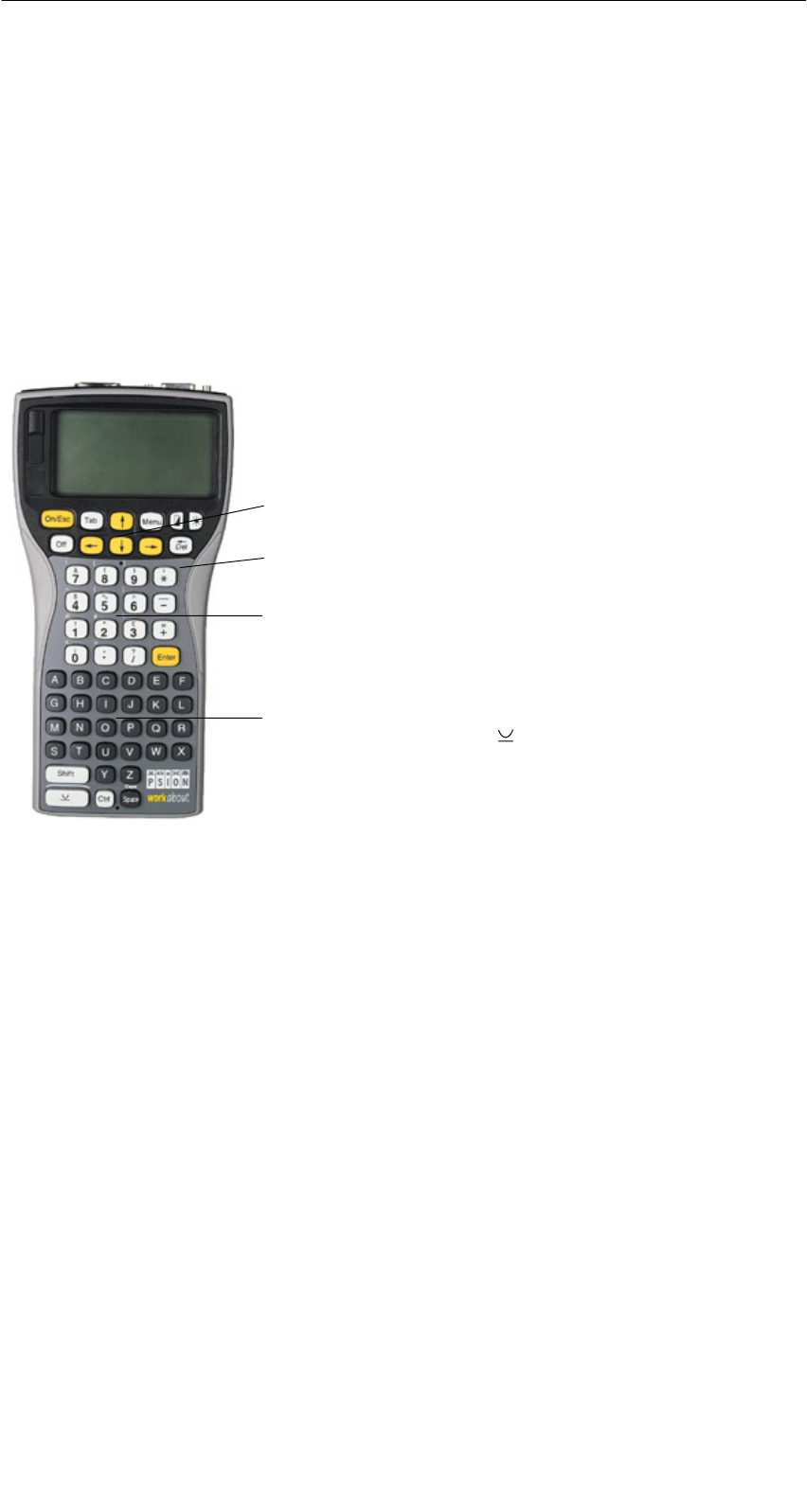
A 01.04
D-8 Handterminal STG
(5)J31069-D0126-U001-A5.1-7418
3 Die Bedienung des STG
3.1 Die Tastatur
Die Tastatur des PSION ist in 3 Teile gegliedert:
S11 Steuertasten direkt unterhalb des Displays
Snumerischer Ziffernblock mit 16 Tasten
SASCII-Tastatur (30 Tasten) inkl. Umschaltetasten
ASCII-Tastatur, sowie Umschalt- und Sonder-
funktionstasten (Ctrl, )
Steuertasten: Kontrast; Displaybeleuchtung;
Ein-/Aus; Cursortasten
Numerischer Eingabeblock mit Enter-Taste
grüne Leuchtdiode; leuchtet, wenn der Akku
geladen wird
Die Bedienung des STG

A 01.04
D-9
Handterminal STG
(5)J31069-D0126-U001-A5.1-7418
3.2 Die Antenne am Lesekopf und das Antennenfeld
3.2.1 MOBY D/E/F/I
Die Antenne des Lesekopfes ist an der oberen Seite des Handterminals ent-
sprechend dem nachfolgenden Bild angeordnet.
Lesen eines MDS
Mit unterschiedlichen MDS-Typen werden unterschiedliche Reichweiten erzielt.
Die folgende Tabelle gibt einen Überblick:
MOBY D MOBY E MOBY F MOBY I
MDS-Typ mm MDS-Typ mm MDS-Typ mm MDS-Typ mm
D139 60 E600 (ISO-Card) 18 F125 80 402/401 6
D160 25 E611 30 F415 50 404/514/413E 20
Labels auf
Bi ICd
6
E624 (Knopf) 8 F124 60 403 8
Basis I-Code:6E623 (Pille)44/35506 12
I-Code1 75 439E 12
I-Code SLI 100 507
(i B i)
35
Tag-it HF-I 100 (mit Batterie)
my-d 100 507 (ohne
Batterie)
4
4 Die Pille kann nur an dem hierfür vorgesehenen Kopfteil gelesen werden.
5 wenn MDS in Metall eingebaut ist
6 Fertigungsbedingt ist mit Reichweitentoleranzen zu rechnen. Die Reichweiten gelten
für Labels der Größe 85 x 55 mm.
Die Bedienung des STG

A 01.04
D-10 Handterminal STG
(5)J31069-D0126-U001-A5.1-7418
Das Antennenfeld beim STG-Lesekopf
z. B.:
MDS E600
z. B.:
MDS E623
MOBY D/E/F MOBY E/I
Knopfantenne bzw.
Stabantenne (MOBY I)
Flächen-
antenne
Das Antennenfeld bei MOBY E
Beim MOBY E-Lesekopf sind 2 Antennen im Leser integriert. Je nachdem, wel-
chen MDS Sie lesen möchten, müssen Sie diesen entsprechend am Lesekopf
positionieren. Die Umschaltung des Antennenfeldes geschieht mit dem Befehl
Extras/ANTENNE (siehe Kap. 4.5.3). Wichtig ist dabei, dass der MDS E623 nur
an der hierfür vorgesehenen Antenne (siehe Bild) gelesen werden kann. Der
MDS E624 kann sowohl an der Knopfantenne als auch an der Flächenantenne
gelesen werden.
Die Bedienung des STG

A 01.04
D-11
Handterminal STG
(5)J31069-D0126-U001-A5.1-7418
3.2.2 MOBY U
Die eigentliche Antenne des Handterminals STG U befindet sich an der Rück-
seite der MOBY U-Antenne (siehe folgendes Bild). Folglich liegt die Abstrahl-
richtung senkrecht zur Rückseite der MOBY U-Antenne. Das kegelförmige An-
tennenfeld hat einen Öffnungswinkel von ca. 90 Grad. Die maximale Feldlänge
(Grenzabstand) beträgt 3 Meter. Sie kann über das Menü “Extras” in Stufen
von 0,5 m eingestellt werden.
Rückseite der MOBY U-Antenne
Antenne
Die Bedienung des STG
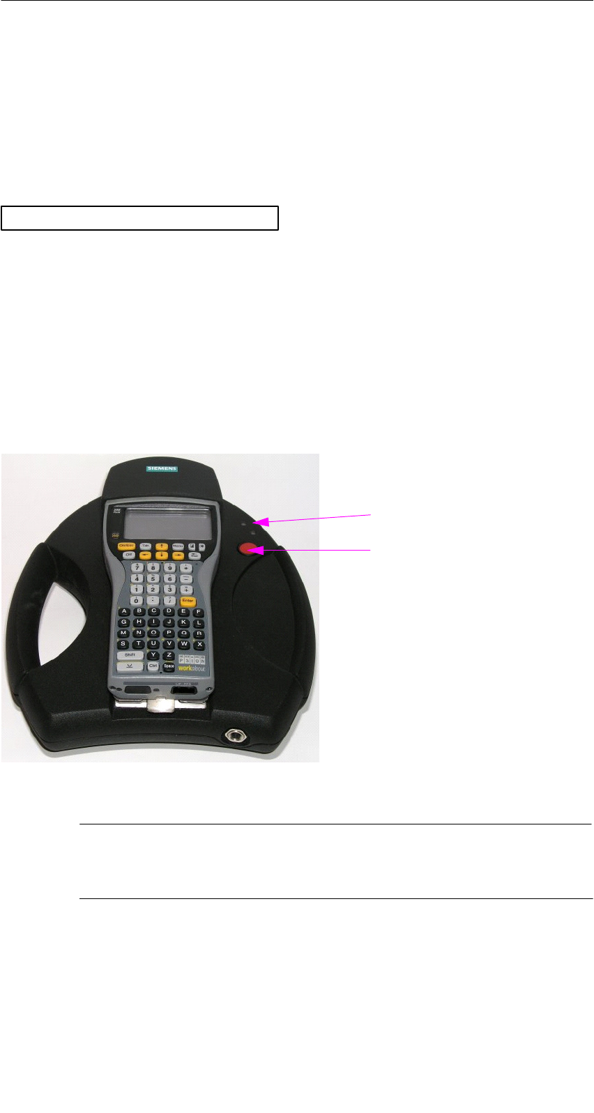
A 01.04
D-12 Handterminal STG
(5)J31069-D0126-U001-A5.1-7418
3.3 Bedienung der MOBY U-Antenne
Die MDS-Funktionen (z. B. Schreiben, Lesen, Initialisieren) werden beim Hand-
terminal STG U erst nach der Betätigung der Kommunikationstaste ausgelöst.
Über die Taste “Menu” wählen Sie die entsprechende MDS-Funktion aus. Im
Display erscheint die Meldung:
ESC um Abzubrechen
Warten auf ENTER von Antenne
Anschließend müssen Sie das Handterminal STG U auf den gewünschten
MDS Uxxx ausrichten und die Kommunikationstaste betätigen.
Nach Betätigung der Kommunikationstaste wird die Antenne eingeschaltet, die
MDS-Funktion ausgeführt und anschließend die Antenne wieder ausgeschaltet.
Solange die Antenne aktiv ist, leuchtet die LED für Kommunikation gelb. Das
Einschalten der Antenne dauert ca. 2 Sekunden. In Abhängigkeit des Datenvo-
lumens und der MDS-Erkennung beträgt die kürzeste Einschaltdauer ca. 3 Se-
kunden.
Handterminal STG U
LED für Kommunikation
Kommunikationstaste
Hinweis
Wenn der Ladezustand der Akkus für die Kommunikation nicht aus-
reichend ist, leuchtet die LED für Kommunikation rot.
Die Bedienung des STG

A 01.04
D-13
Handterminal STG
(5)J31069-D0126-U001-A5.1-7418
3.4 Die Ladefunktion
Sobald Sie das PSION Workabout in die Wand- oder Fahrzeughalterung stek-
ken, wird der Ladevorgang der Akkus gestartet. Das Laden wird aktiviert und
an einer grünen Leuchtdiode angezeigt (siehe Kap. 3.1).
Bei leeren Akkus dauert eine komplette Ladung mindestens 14 Stunden.
Schnellladung der Akkus
Die von Siemens mitgelieferten Akkus für das PSION Workabout sind schnell-
ladefähig. Damit kann das MOBY-Handterminal direkt in dem von PSION er-
hältlichen Schnellladegerät betrieben werden (Vollladung in 1 Stunde).
Einsetzen anderer Batterien
In das PSION Workabout können auch andere Batterien der Größe AA einge-
setzt werden. Das können sowohl wiederaufladbare NiCd-Akkus wie auch
nichtaufladbare Alkalibatterien sein.
WICHTIG: Unbedingt das PSION-Benutzerhandbuch beachten.
Die Backup-Batterie
Die Backup-Batterie im PSION Workabout dient zum Erhalt der Anwendungs-
daten, wenn die Hauptbatterien entladen sind. Die Backup-Batterie ist eine
Lithiumzelle, die nicht geladen werden kann. Bitte beachten Sie, dass eine
neue Backup-Batterie (bei entleerter oder entfernter Hauptbatterie) die Daten
im RAM nur wenige Tage erhalten kann.
Die Bedienung des STG
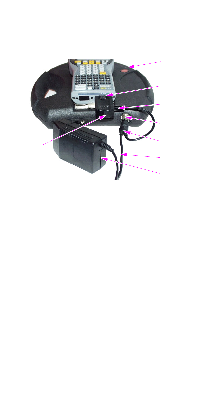
A 01.04
D-14 Handterminal STG
(5)J31069-D0126-U001-A5.1-7418
Handterminal STG U laden
Die Akkus des Handterminals STG U (im PSION Workabout und in der
MOBY U-Antenne) können mit nur einem Netzteil (6GT2 503-1DA00) geladen
werden.
Handterminal STG U mit angeschlossenem Netzteil zum Laden der Akkus
LED für Laden
der Akkus
Ladebuchse des
PSION Workabout
Stecker für
Ladeadapter
Ladebuchse der
MOBY U-Antenne
Kabelweiche am
Ladekabel
Ladekabel
Netzteil
Ladeadapter
für das PSION
Workabout
Schließen Sie das Netzteil zum Laden der Akkus wie folgt an:
SLadeadapter auf die Ladebuchse des PSION Workabout stecken
SStecker an der Kabelweiche des Ladekabels auf die Ladebuchse der
MOBY U-Antenne stecken
SStecker für Ladeadapter am Ladekabel auf den Ladeadapter stecken
SNetzstecker des Netzteils anschließen
Der Ladestatus des Akku-Packs der MOBY U-Antenne wird durch die LED für
das Laden der Akkus angezeigt.
Sgelb: Der Akku-Pack der MOBY U-Antenne wird geladen.
Sgrün: Der Akku-Pack der MOBY U-Antenne ist geladen.
Srot: Das Gerät ist defekt.
Am PSION Workabout leuchtet während des Ladens eine grüne LED (siehe
Kap. 3.1).
Die Bedienung des STG

A 01.04
D-15
Handterminal STG
(5)J31069-D0126-U001-A5.1-7418
Die Ladedauer bei leeren Akkus beträgt
Sfür die MOBY U-Antenne mindestens 1,5 Stunden,
Sfür das PSION Workabout mindestens 14 Stunden.
Das Handterminal STG U kann auch während des Ladens betrieben werden.
Hinweis
SDas PSION Workabout kann nur geladen werden, wenn es mit
PSION Originalakkus bestückt ist.
SFür das Laden des Akku-Packs der MOBY U-Antenne gilt ein ein-
geschränkter Temperaturbereich: 0 °C bis +40 °C
Die Bedienung des STG

A 01.04
D-16 Handterminal STG
(5)J31069-D0126-U001-A5.1-7418
3.5 Akku-Pack der MOBY U-Antenne wechseln
Der Akku der MOBY U-Antenne ist ein Lithium-Ionen-Akku-Pack. Er hat eine
Lebensdauer von ca. 500 Ladezyklen.
Wenn die Kapazität des Akku-Packs soweit abgenommen hat, dass die Be-
triebsdauer der MOBY U-Antenne für die Anwendung nicht mehr ausreichend
ist, dann muss der Akku-Pack ausgetauscht werden.
Lösen Sie die 9 Schrauben an der rückseitigen Gehäuseschale der Antenne
und nehmen die Schale ab. Tauschen Sie den Akku-Pack aus. Setzen Sie die
Gehäuseschale wieder auf und schrauben sie fest.
Hinweis
SBeim Tausch des Akku-Packs darf das Netzteil nicht am Handter-
minal STG U angeschlossen sein.
SDas PSION Workabout braucht nicht von der MOBY U-Antenne
getrennt werden, muss aber während des Tauschs ausgeschaltet
sein.
Hinweis
Der Ersatz-Akku-Pack für die MOBY U-Antenne hat die Bestellnum-
mer 6GT2 594-0AB00.
!Warnung
Der Akku-Pack der MOBY U-Antenne sowie der Ersatz-Akku-Pack
bestehen aus Lithium-Ionen-Akkus. Im Zusammenhang damit ist
Folgendes zu beachten:
SVermeiden Sie das Risiko von Feuer, Explosionen und schweren
Verbrennungen.
SDer Akku-Pack darf nicht über 100 °C erwärmt werden.
SDer Akku-Pack darf nicht auseinandergebaut oder zerstört wer-
den.
Er kann durch unsachgemäße Behandlung, Beschädigung oder
Berührung seines Inhaltes mit Wasser explodieren.
SDie nationalen Entsorgungswege für verbrauchte Akkus/Batterien
sind einzuhalten.
Die Bedienung des STG

A 01.04
D-17
Handterminal STG
(5)J31069-D0126-U001-A5.1-7418
4 Die Programme “MOBY D/E/F/I/U”
Nach dem Einschalten des STG erscheint am Display der Editor. Sie können
nun die Daten anschauen, neue Daten eingeben oder über die Taste “Menu”
eine Funktion aufrufen. Ein direkter Aufruf der Funktionen ist über die Taste
ebenfalls möglich. Drücken Sie hierzu gleichzeitig die Taste und die entspre-
chende alphanumerische Taste. Die folgende Tabelle zeigt alle Funktionen und
die dazugehörigen Kurzaufrufe:
Befehl Kurzaufruf Beschreibung
Datei/Laden Datei D bzw. F31Datei vom PSION RAM-Laufwerk in den
Arbeitsspeicher laden
Datei/Speichern C bzw. F41Gelesene MDS-Daten auf das
RAM-Laufwerk speichern
Datei/Beenden X STG-Anwendung beenden
MDS/Lesen L bzw. F11Daten vom MDS lesen
MDS/Schreiben S bzw. F21Daten auf MDS schreiben
MDS/Loeschen/Init E MDS mit bestimmten Wert beschreiben
MDS/MDS Status N3MDS-Status lesen
MDS/Lese TagId TID-Nummer des MDS lesen
MDS/Lese OTP B3Daten vom OTP-Speicher lesen
MDS/Schreibe OTP I3Daten auf OTP-Speicher schreiben
MDS/Roh-Daten lesen R2Physikalischen Speicher des MDS ausle-
sen
Editor/Sprung zur Adresse J bzw. Tab Im Editor zu einer bestimmten Adresse
springen
Editor/Anzeige O Optionen der Anzeige ändern
Editor/Anzeige loeschen FDaten im Editor auf bestimmten Wert
löschen
Editor/Datum editieren ADas Datum an der Cursorposition in ver-
schiedenen Formaten bearbeiten
Extras/Kommunikation K Optionen in der Kommunikation ändern
Extras/Passwort für STG PPasswort für die STG-Anwendung
ändern
Extras/Adressen Setup GEingaben für die Befehle “MDS lesen/
schreiben” definieren
Extras/MOBY I Setup BSpeichergröße und MOBY I-Betriebsar-
ten einstellen
Die Programme “MOBY D/E/F/I/U”

A 01.04
D-18 Handterminal STG
(5)J31069-D0126-U001-A5.1-7418
Befehl BeschreibungKurzaufruf
Extras/MOBY E Setup YUmschaltung des MDS-Zugriffs
vom “MOBY-Schlüssel” (A) auf den
B-Schlüssel
Feldbetriebsart bei MOBY E SIM: Um-
schaltung zwischen zyklischem Betrieb
und Dauerbetrieb
Extras/MOBY U Setup M3MDS-Speichergröße und Reichweitenbe-
grenzung definieren
Extras/SLG Status Q3Status der MOBY U-Antenne lesen
?/Sprache H Menüsprache einstellen
?/Ueber U Herstellerdaten
?/Version V Version von Betriebssystem und
STG-Anwendung
1 Diese Tasten stehen nur auf einem Handterminal mit numerischer Tastatur zur
Verfügung.
2 Nicht MOBY U.
3 Nur MOBY U.
Die Programme “MOBY D/E/F/I/U”

A 01.04
D-19
Handterminal STG
(5)J31069-D0126-U001-A5.1-7418
4.1 Der Dateneditor
Das Editieren der MDS-Daten kann im Editorfenster in Hexadezimal oder in
ASCII erfolgen. Die Umschaltung erfolgt im Menü EDITOR/ANZEIGE.
Im Editor ist immer die gesamte Größe
eines MDS-Speichers abgebildet. Sie
können mit den Cursorfunktionen zu den
einzelnen Adressen gelangen. Ein
Sprung zu einer beliebigen Adresse
kann mit der “Tab”-Taste durchgeführt
werden (siehe Kap. 4.4.1)
Anzeige des aktuell eingestellten Lese-
kopfes (vgl. Kap. 4.5.1)
Die TagId des MDS wird nur bei
MOBY D/E/F/U angezeigt. Sie ist gültig
nach dem Ausführen der Funktion
“MDS/Lesen-Schreiben-LeseTagId”
Datumfeld:
Das Datum, an dem sich der Cursor be-
findet, wird alternativ in den Formaten
Hex, Dec, ASCII oder Bin dargestellt.
Mit der Funktion “Editor/Datum editieren”
kann der Wert im Datumfeld verändert
werden.
Das Editor-Fenster beinhaltet die MDS-
Daten. Standardmäßig werden 32 Byte
dargestellt.
MDS-Adressen werden hexadezimal
oder dezimal dargestellt.
Die Programme “MOBY D/E/F/I/U”
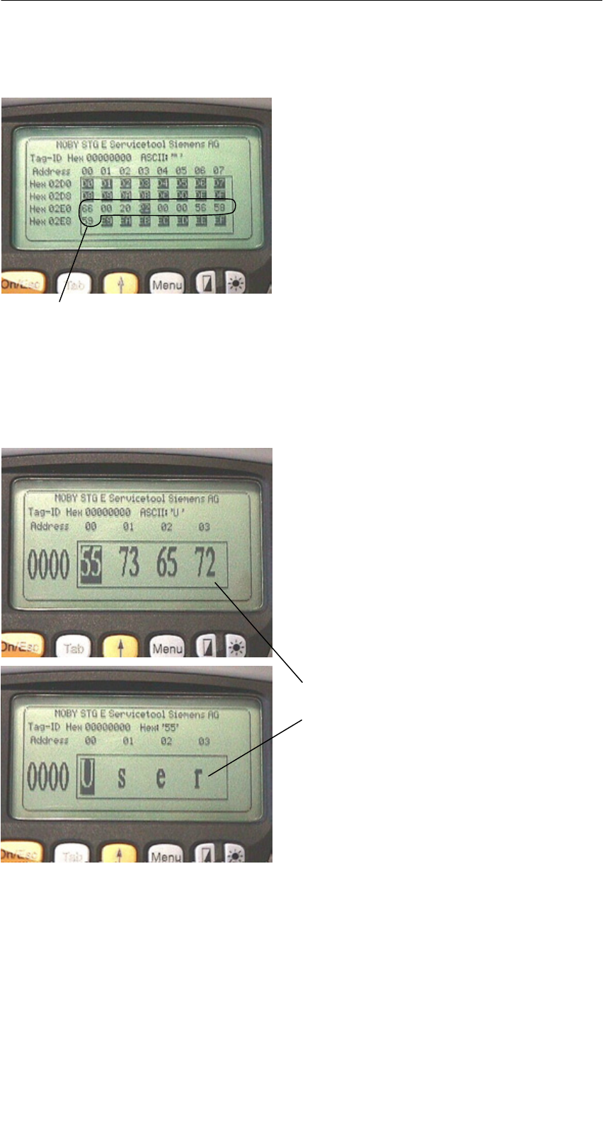
A 01.04
D-20 Handterminal STG
(5)J31069-D0126-U001-A5.1-7418
Der “Aktuelle Bereich”
Aktueller Bereich
Der “Aktuelle Bereich” wird im Editor in
normaler Darstellung angezeigt. Alle an-
deren Datenbereiche des MDS werden
invertiert dargestellt. Der Aktuelle Be-
reich zeigt den zuletzt gelesenen Daten-
block an. Beim Lesen/Schreiben wird
der Aktuelle Bereich als Wert für den
Schreibbefehl eingetragen.
Dieser Wert kann jedoch im Menü
MDS/SCHREIBEN bzw. MDS/LESEN
angepasst werden.
Eine Veränderung des Aktuellen Bereiches geschieht automatisch, wenn Sie
Daten editieren und überschreiben.
Die Größe des am Display dargestellten Speicherbereichs kann über die
Funktion EDITOR/ANZEIGE umgeschaltet werden: (siehe Kap. 4.4.2)
In der Normaldarstellung werden 32
Byte in kleinen Buchstaben dargestellt.
Sie erhalten einen Überblick über die
MDS-Daten.
In der Zoomdarstellung werden nur
4 aufeinanderfolgende Byte angezeigt.
Die Darstellung ist in großen Buchsta-
ben. Das Ablesen vom Display ist ohne
Anstrengung möglich.
Zoomdarstellung hexadezimal
Zoomdarstellung ASCII
Die Programme “MOBY D/E/F/I/U”
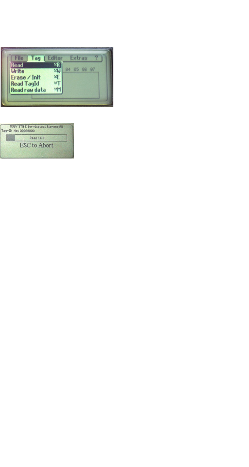
A 01.04
D-21
Handterminal STG
(5)J31069-D0126-U001-A5.1-7418
4.2 Die MDS-Funktionen
Nach dem Start eines Befehls wird auf
dem Display ein Fenster mit einem Bal-
ken dargestellt. Dieser zeigt an, wieviel
Prozent des Befehls bereits abgearbeitet
sind.
Die MDS-Funktionen führen eine Kom-
munikation mit dem MDS durch.
Die MDS-Funktion wird nicht unterbro-
chen, wenn Sie kurzzeitig den MDS aus
dem Lesefeld bewegen. Wird der MDS
länger als 30 Sekunden nicht bearbeitet,
so wird die Funktion unterbrochen
(siehe Kap. 4.5).
4.2.1 Allgemeines zu Lesen und Beschreiben eines MDS
Die MDS von MOBY D, MOBY E und MOBY F haben einen blockorientierten
Datenzugriff. Ein Lesen oder Beschreiben eines MDS ist nur von einem Block-
anfang möglich.
Ein Block hat bei MOBY E/F jeweils eine Länge von 16 Byte (bzw. 10 Hex). Die
beim STG einzugebenden Anfangsadressen für die MDS-Bearbeitung sind
demnach: 00, 10, 20, 30 hex usw.
Ein Block hat bei MOBY D jeweils eine Länge von 4 Byte (I-Code, Tag-it) oder
8 Byte (my-d). Die Anfangsadressen sind demnach:
00, 04, 08, 12 hex ... (I-Code, Tag-it) oder
00, 08, 10, 18 hex ... (my-d).
Bei MOBY D/E/F/U wird nach dem Lesen/Schreiben die TagId im Display auto-
matisch auf den aktuellen Wert gebracht.
Die Programme “MOBY D/E/F/I/U”
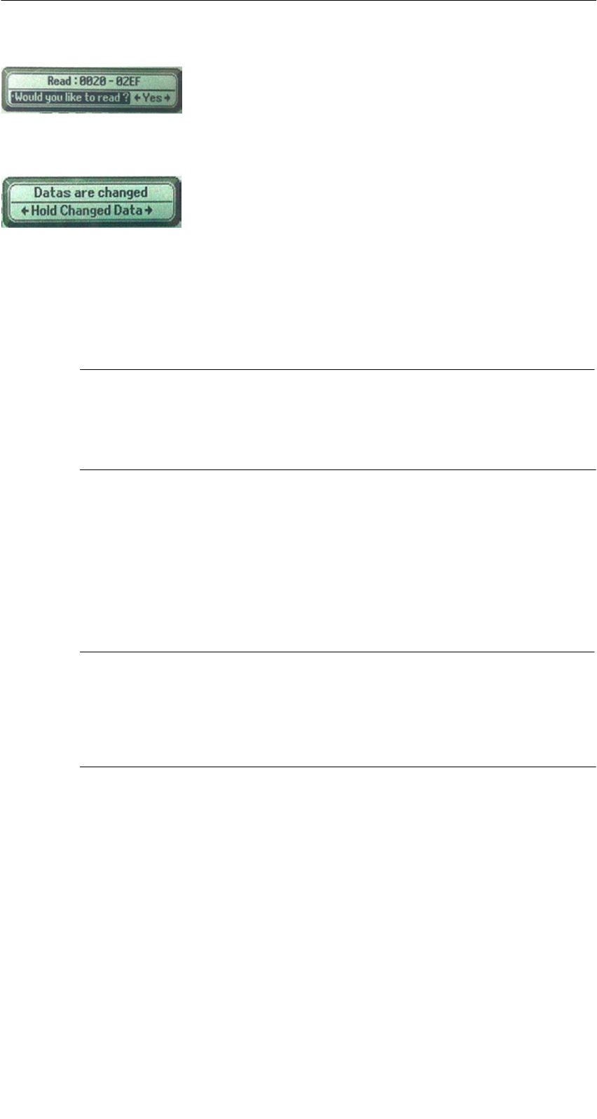
A 01.04
D-22 Handterminal STG
(5)J31069-D0126-U001-A5.1-7418
Es ist jedoch möglich, jede beliebige Anfangs-
adresse anzugeben. Diese wird vom STG akzeptiert
und auf den nächstniedrigeren Blockanfang korri-
giert. Die Adresskorrektur wird dem Bediener in ei-
nem Fenster angezeigt und muss quittiert werden.
Ein weiteres Fenster erscheint, wenn Sie im Editor
Daten geändert haben und anschließend versuchen,
einen MDS zu lesen. Hier macht Sie ein Hinweis dar-
auf aufmerksam, dass die soeben geänderten Daten
mit dem MDS-Lesebefehl möglicherweise wieder
überschrieben werden. Sie haben die Möglichkeit, die
geänderten Daten im Editor zu behalten, zu verwerfen
oder den Befehl komplett abzubrechen.
Hinweis
Am Handterminal kann nur bei MOBY I der ECC-Mode eingestellt
werden.
Bei MOBY D/E/F/U ist die ECC-Betriebsart nicht möglich.
4.2.2 MDS lesen
Es kann ein Datenblock mit einer frei definierbaren Anfangs- und Endadresse
vom MDS gelesen werden. Wird für Anfangs- und Endadresse der gleiche Wert
eingegeben, so kann vom MDS nur ein Block gelesen werden. Der Adressbe-
reich wird in einem weiteren Fenster zur Bestätigung angezeigt.
Hinweis
Wurde im Menü “Extras/Adressen Setup/........” im Feld Lesen/
Schreiben der Modus “MDS komplett” gewählt, so wird die Funktion
“MDS/Lesen” ohne weitere Nachfrage sofort gestartet. Es wird im-
mer der gesamte MDS bearbeitet.
Die Programme “MOBY D/E/F/I/U”

A 01.04
D-23
Handterminal STG
(5)J31069-D0126-U001-A5.1-7418
4.2.3 MDS beschreiben
Es kann ein Datenblock auf den MDS geschrieben werden. Der im Editor gül-
tige Datenblock wird dabei als Default bei jedem Schreibvorgang angezeigt.
Die Defaultlänge bzw. Endadresse kann beim Beschreiben noch auf einen an-
deren Wert geändert werden.
4.2.4 MDS löschen/Initialisieren
Die Funktion “MDS löschen/Init” dient dazu, sehr schnell den kompletten MDS
mit einem bestimmten Wert zu beschreiben. Der Löschwert kann in einem Fol-
gemenü eingegeben werden. Nach der Löschfunktion ist der Speicher im Editor
ebenfalls auf den eingegebenen Wert gelöscht. Bei MOBY I/U muss vor dieser
Funktion die richtige MDS-Speichergröße eingestellt sein (Extras/MOBY I
Setup oder Extras/MOBY U Setup).
Die Programme “MOBY D/E/F/I/U”

A 01.04
D-24 Handterminal STG
(5)J31069-D0126-U001-A5.1-7418
4.2.5 MDS-Status lesen
Nur MOBY U: Die Funktion liest die Statusdaten vom MDS aus und zeigt sie
an.
MDS-Statusinformationen:
SMDS-Nummer (8 stellige hexadezimale Darstellung) und MDS-Speicher-
größe (2 oder 32 kB)
SDaten für die Berechnung der Batterielebensdauer (“Summe Zugriffe”,
“Summe Suche” und “Aender. Sleep Time”)
SRestliche Batterielebensdauer des MDS in %
SEingestellte Sleep Time im MDS
Hinweis
Für die Berechnung der Batterielebensdauer der MOBY U-Daten-
träger benötigt die STG-Software unbedingt die aktuelle Kalender-
woche und das aktuelle Kalenderjahr. Deshalb muss im PSION
Workabout das Datum korrekt eingestellt sein.
Das Datum können Sie über das Systemmenü “Time” → “Time and
date” einstellen.
Gehen Sie hierzu wie folgt vor:
SVerlassen Sie das MOBY U Service- und Testprogramm über
“Datei/Beenden”
SWählen Sie “System screen” aus
SPositionieren Sie den Cursor auf die Anwendung “IMG”
SBetätigen Sie die Taste “Menu”
SWählen Sie “CTRL/Set time and date”
SStellen Sie “Time” und “Date” ein und übernehmen mit der
“Enter”-Taste
SKehren Sie über “IMG” und “Moby_u[A]” in das MOBY U Service-
und Testprogramm zurück
Die Programme “MOBY D/E/F/I/U”

A 01.04
D-25
Handterminal STG
(5)J31069-D0126-U001-A5.1-7418
4.2.6 Lesen der ID-Nummer
Nur MOBY D/E/F/U: Die Funktion liest die Seriennummer vom MDS und zeigt
sie an. Die ID-Nummer wird vom Werk eingestellt und kann nicht verändert
werden.
Die Anzeige der TagId erfolgt im Editor in der zweiten Zeile in hexadezimaler
Form.
Das Lesen der TagId wird bei den Funktionen MDS lesen/schreiben/löschen
automatisch durchgeführt.
4.2.7 OTP-Speicher lesen
Nur MOBY U: Die Funktion liest den kompletten Inhalt (16 Byte) des OTP-Spei-
chers.
Hinweis
Wurde im Menü ”Extras/Adressen Setup/...” im Feld Lesen/Schrei-
ben der Modus ”MDS komplett” gewählt, so wird die Funktion ”MDS/
Lesen” ohne weitere Nachfrage sofort gestartet. Es wird immer der
gesamte MDS bearbeitet.
4.2.8 OTP-Speicher beschreiben
Nur MOBY U: Die Funktion beschreibt den kompletten OTP-Speicher (16 Byte).
Hinweis
Der OTP-Speicher kann nur ein einziges Mal beschrieben werden.
Vor der Ausführung werden Sie noch einmal gefragt, ob Sie die
Funktion tatsächlich ausführen wollen, da diese Aktion unwiderruf-
lich ist.
Die Programme “MOBY D/E/F/I/U”

A 01.04
D-26 Handterminal STG
(5)J31069-D0126-U001-A5.1-7418
4.2.9 Rohdaten lesen
Nur MOBY D/E/F: Mit dieser Funktion wird der komplette Speicher des MDS
physikalisch ausgelesen. Insbesondere werden TagId, Schlüsselinformationen
(soweit Public), Herstellerinformation und MDS-Zugriffsrechte dargestellt. Für
die Interpretation der Daten ist die Kenntnis des physikalischen Speicherauf-
baus des MDS notwendig (siehe Beschreibung MFWAPI bzw. CCTWAPI).
Mit der Funktion “Rohdaten lesen” können Fehler erkannt werden, die bei der
Konfigurierung des MDS entstanden sind.
Hinweis
für MOBY F
Die MDS-Adressen 8 bis 3F hex (Pages 2 bis 15) können nicht gele-
sen werden. Sie werden im Editor immer mit 00 angezeigt.
Die Programme “MOBY D/E/F/I/U”

A 01.04
D-27
Handterminal STG
(5)J31069-D0126-U001-A5.1-7418
4.3 Die Datei-Funktionen
4.3.1 Laden einer Datei
Es kann eine Datei in den STG-Editor geladen werden, die
Svorher mit dem Befehl “Datei/Speichern” abgespeichert wurde oder
Svom PC auf das Laufwerk “RAMDRIVE (M:)” des PSION übertragen wurde
(siehe Kap. 6.2).
4.3.2 Speichern
Die Daten, die gerade im Editor angezeigt werden, können in einem File auf
dem PSION abgespeichert werden. Der Filename kann dabei aus 1 bis 8 Buch-
staben oder Ziffern bestehen. Beim Abspeichern wird dem Filenamen automa-
tisch die Endung “.HEX” (Daten) und “.HX1” (ID-Nr.) hinzugefügt (siehe auch
Kap. 6.2).
Für das Abspeichern von MDS-Daten steht im Handterminal ein Speicherbe-
reich von ca. 1,8 MB zur Verfügung. Bei MOBY E können demnach bis zu
2000 MDS gelesen und gespeichert werden.
4.3.3 Beenden
Mit der Funktion “Beenden” können Sie das STG-Programm von MOBY been-
den. Sie gelangen auf die Betriebssystemebene des PSION-Handterminal
(siehe Kap. 6.3).
Die Programme “MOBY D/E/F/I/U”
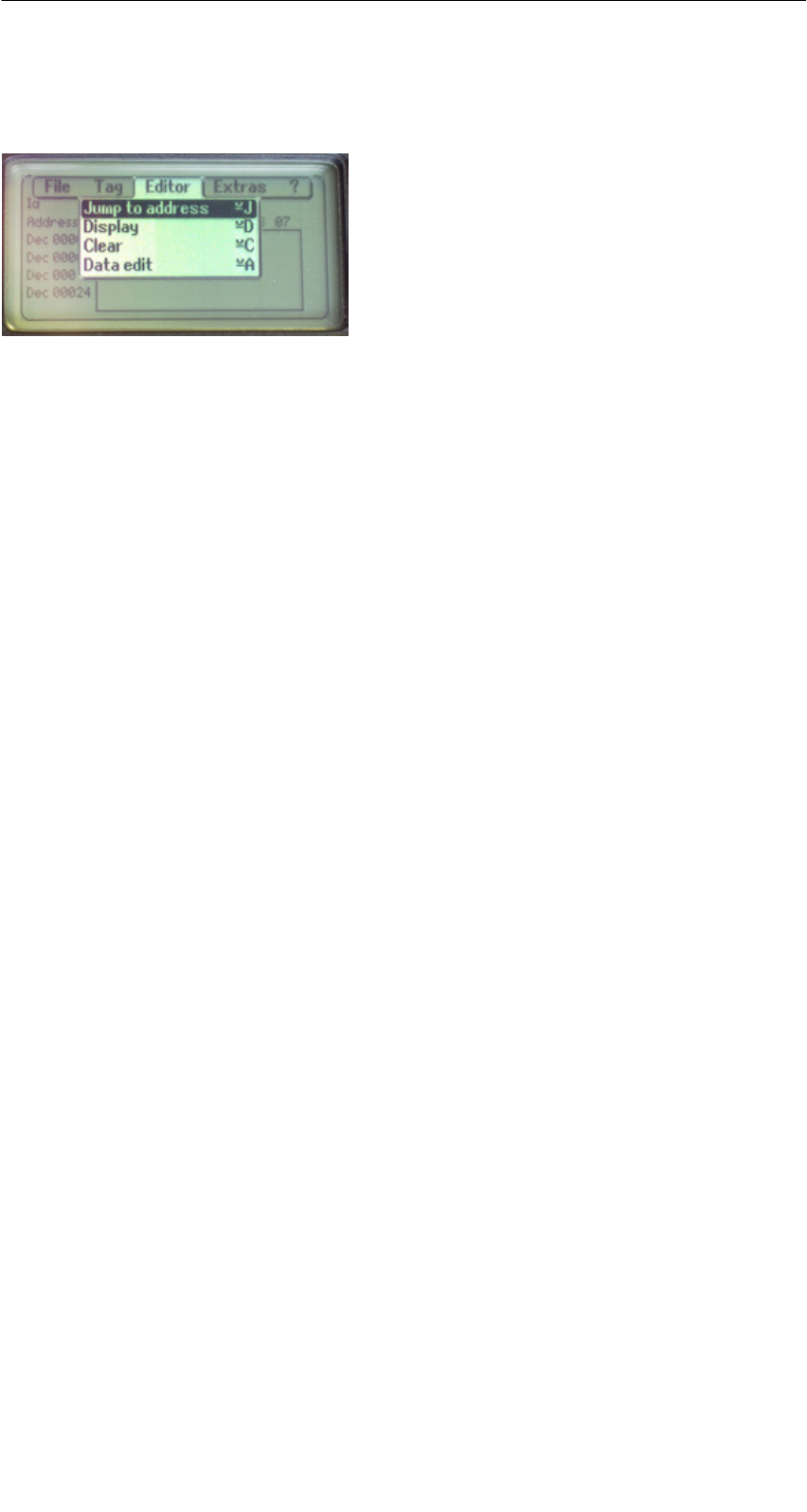
A 01.04
D-28 Handterminal STG
(5)J31069-D0126-U001-A5.1-7418
4.4 Die Funktionen Editor
4.4.1 Sprung zur Adresse
Sie können in dezimaler oder hexadezimaler Form eine Speicheradresse ein-
geben. Die Einstellung kann unter Menüpunkt Display/Display Address verän-
dert werden. Anschließend wird im Editor diese Adresse als Anfangsadresse
dargestellt.
Diese Funktion kann auch direkt im Editor mit der “Tab”-Taste ausgelöst wer-
den.
4.4.2 Anzeige
In diesem Menü erfolgen die Einstellungen
SEditor umschalten zwischen 32 Byte-Darstellung (4x8= kleine Anzeige) und
4 Byte-Darstellung (1x4= große, gut lesbare Zeichen)
SIn der Editor-Darstellung 1x5 wird keine Adresse angezeigt. Diese Anzeige
ist sehr vorteilhaft beim Lesen von Festcode-MDS von MOBY F. Bei anderen
MDS-Typen werden die ersten 5 Byte der gelesenen Daten angezeigt. Ein
Positionieren mit dem Cursor auf andere Adressen ist nicht möglich.
SEditor umschalten zwischen “Hexadezimal”- und “ASCII”-Darstellung. Die
Adressen werden immer in hexadezimaler oder dezimaler Form dargestellt.
SDatum umschalten zwischen “BIN”-, “ASCII”-, “DEZ”- und “HEX”-Darstellung
Die Programme “MOBY D/E/F/I/U”

A 01.04
D-29
Handterminal STG
(5)J31069-D0126-U001-A5.1-7418
4.4.3 Anzeige löschen
Die Funktion “Anzeige löschen” beschreibt den kompletten Speicher im STG-
Editor mit einem Wert, den Sie vorgeben können. Anschließend können Sie im
Editor die gewünschten Daten auf die entsprechenden Werte abändern. Eine
Funktion zum MDS erfolgt dabei nicht.
SDie Anzeige im Datumfeld kann in den Formaten Hexadezimal, ASCII, Dezi-
mal oder Binär erfolgen. Mit dem hier eingestellten Format können die Daten
mit der Funktion “Anzeige/Datum editieren” auch verändert werden.
SDie Anzeige der Adressen kann zwischen Hexadezimal und Dezimal umge-
schaltet werden.
4.4.4 Datum editieren
Die Funktion “Datum editieren” stellt neben den Standardformaten Hex und
ASCII des Editorfensters auch die Formate Dezimal und Binär zur Datenein-
gabe zur Verfügung.
Die Programme “MOBY D/E/F/I/U”
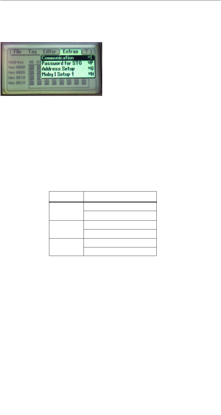
A 01.04
D-30 Handterminal STG
(5)J31069-D0126-U001-A5.1-7418
4.5 Die Funktionen Extras
4.5.1 Kommunikation
SSchnittstelle: Hier erfolgt die Umschaltung zwischen TTL-Schnittstelle
(Lesekopf) und RS 232-Schnittstelle.
Bei RS 232-Einstellung muss das “Protokoll” auf den
Eintrag “MOBY E/SIM” oder “ASM 420/I/V” eingestellt
werden.
Bei MOBY U ist keine Einstellung erforderlich. Die Schnitt-
stelle ist fest auf RS 232 eingestellt.
SProtokoll: Abhängig vom jeweiligen Lesekopf können hier bestimmte
Protokolle eingestellt werden:
Lesekopf einstellbare Protokolle
MOBY D
MOBY D ISO
MOBY E
MOBY E/SIM
MOBY I
ASM 420/I/V
MOBY D
MOBY E
MOBY I
Durch die Einstellung des MOBY-Protokolls wird bei
MOBY E/F auch automatisch die Speichergröße des Editors
festgelegt.
Bei MOBY I wird die Speichergröße des Editors mit der
Funktion “Extras/MOBY I Setup” eingestellt.
Bei MOBY U ist das Protokoll 3964R fest eingestellt. Die
Speichergröße des Editors wird mit der Funktion “Extras/
MOBY U Setup” eingestellt.
Die Programme “MOBY D/E/F/I/U”

A 01.04
D-31
Handterminal STG
(5)J31069-D0126-U001-A5.1-7418
4.5.2 Passwort
Optional können Sie ein Passwort programmieren. Das Passwort muss vor ei-
ner Schreibfunktion eingegeben werden. Ein eingegebenes Passwort bleibt bis
zum Abschalten des STG gültig. D. h., bei mehreren aufeinanderfolgenden
Schreibbefehlen muss das Passwort nur einmal eingegeben werden. Ein Ver-
lassen des “MOBY”-Programmes ist ebenfalls nur mit Passwort möglich.
Default-Passwort
Im Auslieferungszustand hat das Passwort den Wert “123”. Dieses Passwort ist
auch eingestellt, nachdem Sie die Batterien des STG entfernt hatten.
Passwort vergessen?
Wurde ein Passwort vergessen, so gibt es keine Möglichkeit, das Passwort zu-
rückzuerhalten. Die einzige Möglichkeit besteht darin, die Hauptbatterie und die
Knopfzelle aus dem PSION für einige Minuten zu entfernen. Nach dem Wieder-
einsetzen der Batterien und dem Einschalten geht das STG in den Ausliefe-
rungszustand, es hat das Passwort “123”.
Das Passwort 99999999
Die Veränderung des Passworts auf den Wert 99999999 (8x die 9) hat eine be-
sondere Bedeutung:
Die Schreibfunktion auf den MDS sowie die Funktion “Datei/Beenden” ist gene-
rell nicht mehr möglich. Auch das Passwort kann jetzt nicht mehr geändert wer-
den. Die einzige Möglichkeit, jetzt wieder die Schreibfunktion zu erlangen, ist
das Entfernen aller Batterien (siehe auch: Passwort vergessen?)
4.5.3 Antenne
Nur bei MOBY E: Das Antennenfeld am Lesekopf wird umgeschaltet zwischen
“Karte” (große Antenne) und “Pille” (kleine Antenne) (siehe auch Kap. 3.2.1).
Die Antenne muss einmalig bei der Inbetriebnahme des Lesekopfes ein-
gestellt werden. Beim Ausschalten des Handterminals bleibt die einge-
stellte Antenne im Lesekopf gespeichert.
Die Programme “MOBY D/E/F/I/U”

A 01.04
D-32 Handterminal STG
(5)J31069-D0126-U001-A5.1-7418
4.5.4 Adressen Setup
Mit dieser Funktion wird der Aufruf der Befehle “MDS lesen/schreiben” definiert.
SStart-Adresse + Laenge: Die Eingabe der MDS-Adresse beim
Befehl Lesen/Schreiben erfolgt über
eine Startadresse und die Länge der
zu bearbeitenden Daten.
End-Adresse: Die Eingabe der MDS-Adresse beim
Befehl Lesen/Schreiben erfolgt über
Startadresse und Endadresse.
SLesen/Schreiben: Umschaltung von “Block” auf “MDS komplett”. Diese
Einstellung betrifft die Defaulteinstellung bei der Aus-
führung eines MDS-Befehls.
Block: Beim Lesen/Schreiben eines MDS wird
immer der gerade aktive Bereich als der
zu lesende-/schreibende Bereich
angezeigt.
MDS komplett: Beim Lesen/Schreiben eines MDS wird
immer der gesamte MDS bearbeitet.
Die Lese-/Schreibfunktion wird sofort
gestartet. Die Eingabe eines Teilberei-
ches des MDS ist nicht möglich.
Die Programme “MOBY D/E/F/I/U”

A 01.04
D-33
Handterminal STG
(5)J31069-D0126-U001-A5.1-7418
4.5.5 MOBY I Setup
SSpeicher Groesse: Speichergröße des zu bearbeitenden MDS festlegen.
Mit dieser Einstellung wird auch der Speicherbereich im
Editor festgelegt. Es ist nicht möglich, MDS-Speicher-
adressen anzusprechen, die über die Speichergröße
hinausgehen.
SMDS Typ: Es wird zwischen RAM/FRAM und EEPROM unter-
schieden. In der Einstellung RAM/FRAM wird eine leere
MDS-Stützbatterie am STG angezeigt.
SECC: Ein-/Ausschalten des ECC-Treibers
Der Anwendungszweck des ECC-Treibers ist in der
MOBY-Anschaltungsdokumentation beschrieben.
SMDS507: Dieser Parameter ist nur beim Betrieb des MDS 507 auf
“ja” einzustellen. Beim MDS507-Betrieb wird die Dialog-
batterie abgefragt und als Status angezeigt, wenn diese
leer wird.
SAbtastzeit: Die Abtastzeit ist nur beim Betrieb des MDS 507 über
ein ASM 420 von Bedeutung. Der Einstellbereich liegt
zwischen 0,1 s und 6,3 s. Der Defaultwert (0,5 s) muss
in der Regel nicht verändert werden.
4.5.6 MOBY E Setup
SSchlüssel A/B: Es kann zwischen dem “MOBY-Schlüssel” und dem
“B-Transportschlüssel für MIFARE-Datenspeicher”
umgeschaltet werden. Standardmäßig wird immer mit
dem MOBY-Schlüssel gearbeitet. Die Einstellung “B”
gestattet das Bearbeiten vom MIFARE-MDS im Aus-
lieferungszustand (Der B-Schlüssel muss sich im Urzu-
stand befinden).
SFeldbetriebsart: Nur bei MOBY E SIM (vgl. Kap. 6.6): Umschaltung des
SIM vom zyklischen Betrieb in den Dauerbetrieb.
Im Dauerbetrieb erfolgt die Befehlsbearbeitung deutlich
schneller.
SAntenne: Es kann zwischen Karte und Pille umgeschaltet werden.
Die Programme “MOBY D/E/F/I/U”

A 01.04
D-34 Handterminal STG
(5)J31069-D0126-U001-A5.1-7418
4.5.7 MOBY U Setup
SSpeicher Groesse: Speichergröße des zu bearbeitenden MDS festlegen.
Mit dieser Einstellung wird auch der Speicherbereich im
Editor festgelegt. Es ist nicht möglich, MDS-Speicher-
adressen anzusprechen, die über die Speichergröße
hinausgehen.
SStandby-Zeit: Die Standby-Zeit kann in Stufen von 7 ms von 0 ms bis
1400 ms eingestellt werden. Der Defaultwert (AUS)
muss in der Regel nicht verändert werden.
SReichweiten- Die Feldlänge (Grenzabstand) beträgt 3 m und kann
begrenzung: in Stufen von 0,5 m eingestellt werden, um Überreich-
weiten der Antenne zu vermeiden.
Der Einstellbereich liegt zwischen 0,5 m und 3,5 m.
Der Defaultwert beträgt 1 m.
4.5.8 SLG Status
Nur MOBY U: Mit der Funktion SLG Status können Versionsstände und Einstel-
lungen der MOBY U-Antenne ausgelesen werden.
Die Informationen rufen Sie mit der “Enter”-Taste nacheinander in 3 Fenstern
ab.
SFenster 1: Hardware-, Firmware- und Loader-Version
SFenster 2: Treibervariante, Treiberversion und Schnittstellenparameter
SFenster 3: Eingestellte Reichweitenbegrenzung, Standby-Zeit und
Multitag (gleich 1)
Die Programme “MOBY D/E/F/I/U”

A 01.04
D-35
Handterminal STG
(5)J31069-D0126-U001-A5.1-7418
4.6 Die Funktionen “?”
4.6.1 Sprache
Beim STG kann als Menüsprache Deutsch oder Englisch ausgewählt werden.
Die Default-Sprache bei der Inbetriebnahme des STG ist Englisch.
4.6.2 Ueber
Angaben zum Hersteller des STG-Programmes: Siemens AG A&D PT7 M2
4.6.3 Version
Gibt die Version des STG-Programmes, des Betriebssystems EPOC, den Aus-
gabestand der ROM-Version sowie den Ausgabestand der MOBY-Library aus.
Bei Fehlerrückmeldungen an Siemens sind diese Parameter unbedingt anzu-
geben.
Die Programme “MOBY D/E/F/I/U”
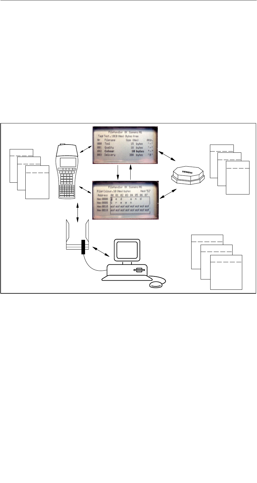
A 01.04
D-36 Handterminal STG
(5)J31069-D0126-U001-A5.1-7418
5 Das Programm “FILEHANDLER”
5.1 Allgemeines zum Filehandler
Wie bei einem PC-basierenden System erfolgt beim Filehandler der Datenzu-
griff über logische Dateinamen und nicht über physikalische Speicheradressen.
Das folgende Bild zeigt den Aufbau und die Arbeitsweise des Programmes
“FILEHANDLER”:
File 3.hex
File 2.hex
File 1.hex
MOBY\File 3.hex
MOBY\File 2.hex
MOBY\File 1.hex
optionale Verbindung zum PC
WORD
EXCEL
.
.
Editor-
Anzeige
Directory-
Anzeige
Dateien im MDS
Dateien im Handterminal
File 3
File 2
File 1
Das Programm “FILEHANDLER” ist so aufgebaut, dass Sie mit den gleichen
Funktionen auf die Handterminal-Dateien und auf die MDS-Dateien zugreifen
können. Die Directory-Anzeige ist für das Handterminal und den MDS verfüg-
bar. Dateien vom MDS können mit nur wenigen Tasten vom MDS zum Handter-
minal kopiert werden (und umgekehrt).
Über eine optionale Verbindung zum PC (3link Kabel; siehe Anhang A.1) kön-
nen die im Handterminal gespeicherten Dateien mit dem PC ausgetauscht wer-
den.
Nun können Sie die Daten mit Ihnen bekannten PC-Programmen weiter bear-
beiten (z. B.: WORD, EXCEL, ...). Voraussetzung ist, dass der Inhalt und die
Datenstruktur des MDS-Files von der PC-Applikation unterstützt werden (siehe
auch Kap. 6).
Das Programm “FILEHANDLER”

A 01.04
D-37
Handterminal STG
(5)J31069-D0126-U001-A5.1-7418
Hinweis
Bitte beachten Sie, dass der Filehandler nur für MOBY I zur Verfü-
gung steht.
5.2 Die Filehandler-Befehle
STG-Befehl Kurzaufruf1Filehandler-
Befehl
Beschreibung
Datei/Lese Datei vom
MDS
R bzw. F12,
bzw. Enter
READ Eine Datei vom MDS lesen
Datei/Lese Datei vom
STG RAM
S bzw. F32–Eine Datei vom RAM des
Handterminals lesen
Datei/Schreibe Datei
auf MDS
W bzw. F22WRITE Eine Datei auf den MDS
schreiben
Datei/Schreibe Datei
auf STG RAM
T bzw. F42–Die Daten vom Editor auf
das Handterminal schreiben
Datei/Lese Verz. vom
MDS
G DIR Directory vom MDS einlesen
und anzeigen
Datei/Lese Verz. vom
STG RAM
P – Directory des STG (RAM-
Speicher) anzeigen
Datei/Beenden X – Filehandler-Anwendung be-
enden
Befehle/Datei neu B CREATE Neue Datei mit Länge 0 auf
dem MDS anlegen
Befehle/Datei loe-
schen
D bzw. Del3DELETE Datei auf dem MDS löschen
Befehle/MDS Format I FORMAT Den MDS formatieren
Befehle/Datei Attribut Y ATTRIB Datei auf dem MDS mit Zug-
riffsrechten versehen
Befehle/MDS Status FMDS STATUS MDS Status auslesen
Befehle/MDS Cover C COVER Datenstruktur des MDS
schützen
Editor/Anzeige Ver-
zeichnis
Q – letzte gelesene Directory an-
zeigen
Editor/Anzeige Editor U – Filedaten anzeigen
Editor/Datei Groesse N – Filegröße in Editor ändern
Das Programm “FILEHANDLER”

A 01.04
D-38 Handterminal STG
(5)J31069-D0126-U001-A5.1-7418
STG-Befehl BeschreibungFilehandler-
Befehl
Kurzaufruf1
Editor/Anzeige loe-
schen
J – Anzeige mit bestimmtem
Wert beschreiben
Editor/Sprung an
Adresse
O bzw. Tab –Cursor auf Adressposition
bringen
Editor/Anzeige Setup H – Anzeige zwischen ASCII-
und HEX-Darstellung um-
schalten
Extras/Parameter Z – Filehandler-Parameter ein-
stellen
Extras/Passwort fuer
FH
A – Passworteinstellung für das
Programm “FILEHANDLER”
Extras/Kommunikation E – Einstellung: Lesekopf oder
ASM
?/Sprache L – Menüsprache einstellen
?/Ueber K – Herstellerdaten
?/Version V – Version von Betriebssystem
und Filehandler
1 Der Kurzaufruf der Befehle erfolgt über die Tastenkombination + Taste. Hierzu
müssen beide Tasten gleichzeitig gedrückt werden. Die Tasten für die Kurzaufrufe
von MDS-Befehlen sind identisch mit den Buchstaben, wie sie auch über den FC in
der SIMATIC angesprochen werden.
2 Die Tasten F1 bis F4 stehen nur auf einem Handterminal mit numerischer Tastatur zur
Verfügung.
3 In der Directory-Ansicht kann mit der “Del”-Taste das gerade ausgewählte File ge-
löscht werden. Damit können auch Dateien vom RAM des Handterminals gelöscht
werden.
Das Programm “FILEHANDLER”
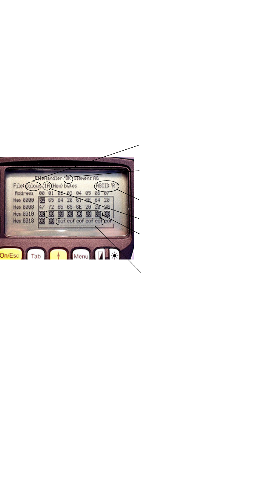
A 01.04
D-39
Handterminal STG
(5)J31069-D0126-U001-A5.1-7418
5.3 Die Anzeigen Editor und Directory
Die Bildschirmanzeige beim Filehandler befindet sich entweder in der “Direc-
tory-Anzeige” oder in der “Editor-Anzeige”. Über das Menü “Editor/Anzeige Edi-
tor” und “Editor/Anzeige Directory” kann zwischen den beiden Anzeigen umge-
schaltet werden.
5.3.1 Der Dateneditor im Filehandler
Der Dateneditor beim Filehandler ist ähnlich aufgebaut wie beim Standard-
STG-Programm (siehe Kap. 4.1).
Eingestellte MDS-Speichergröße. Sie
kann über den Befehl Extras/Parame-
ter eingestellt werden.
Name des Files im Editor. Die Datei
kann sowohl vom MDS als auch vom
Handtermianlspeicher gelesen wor-
den sein.
Das Datum, an dem sich der Cursor
befindet, wird alternativ im ASCII-For-
mat dargestellt.
Hier wird die Filelänge angezeigt.
Der Datenbereich, der größer ist als
die Filelänge, wird mit dem Daten-
string “eof” (end-of-file) gekennzeich-
net.
Wird die Dateigröße verlängert
(siehe Kap. 5.6.3), so werden die
verlängerten Daten invertiert darge-
stellt.
Das Programm “FILEHANDLER”
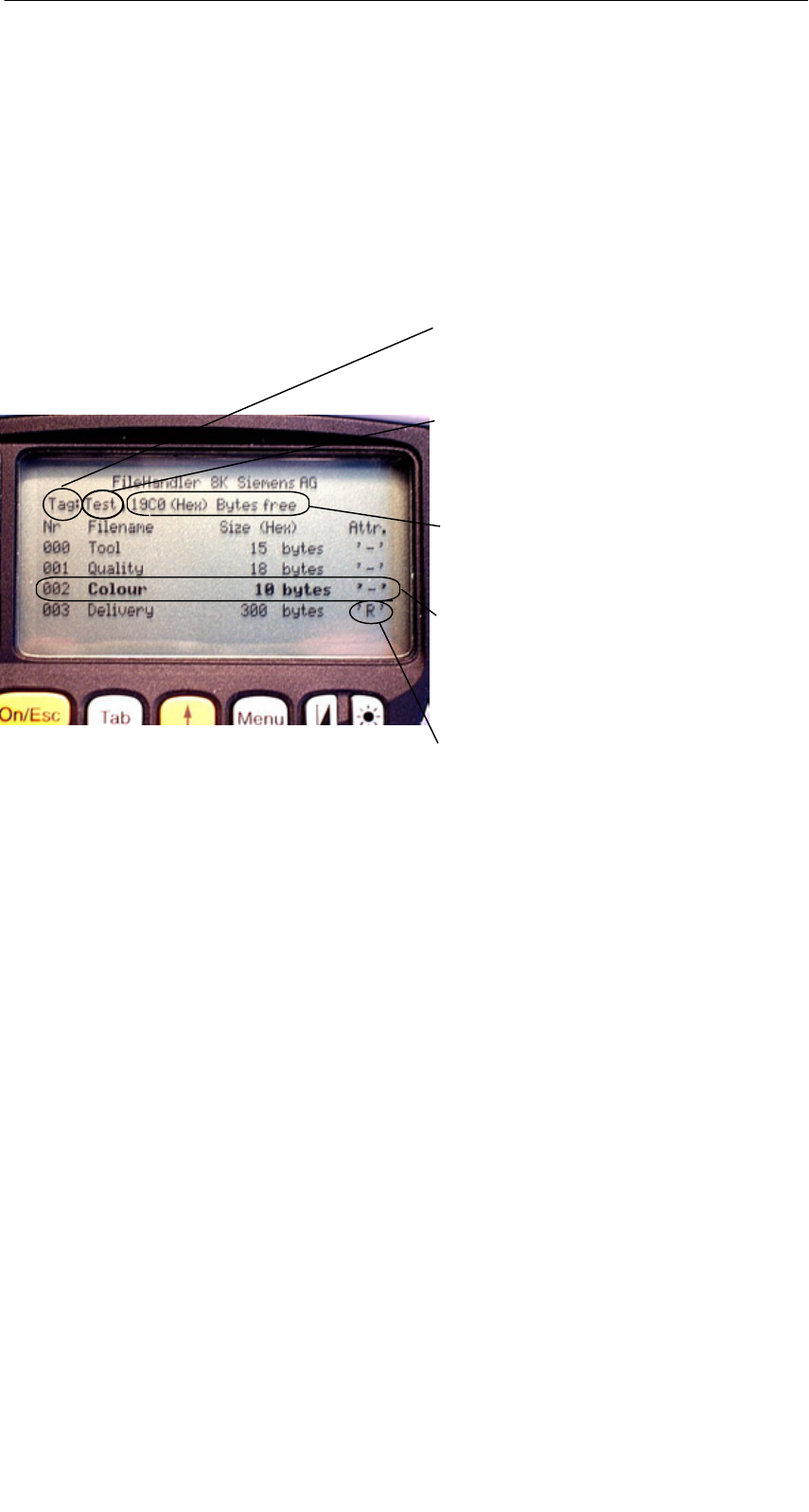
A 01.04
D-40 Handterminal STG
(5)J31069-D0126-U001-A5.1-7418
5.3.2 Die Directory-Ansicht
In der Directory-Ansicht werden entweder alle Dateien vom MDS oder vom
RAM des STG angezeigt. Mit Hilfe der Directory-Ansicht können sehr effektiv
Dateien vom MDS gelesen bzw. zwischen Handterminal und MDS kopiert wer-
den (siehe Kap. 5.4).
Aufbau der Directory-Anzeige
Hier wird angezeigt, ob das angezeigte
Directory von einem “MDS” oder vom
“Handterminal” stammt.
Name, mit dem der MDS formatiert
wurde. Beim Handterminal-Directory
wird kein Name angezeigt.
Freier Speicher auf dem MDS. Beim
Handterminal sind das ca. 1,8 MB
nach der Inbetriebnahme.
Mit den Cursortasten kann eine Datei
ausgewählt werden. Nach der Aus-
wahl kann direkt eine Funktion mit
dieser Datei ausgeführt werden (siehe
Kap. 5.4).
Bei den MDS-Dateien kann hier ein
Attribut eingetragen sein (siehe
Kap. 5.5.4). Bei Handterminal-Da-
teien können keine Attribute gesetzt
werden.
Das Programm “FILEHANDLER”
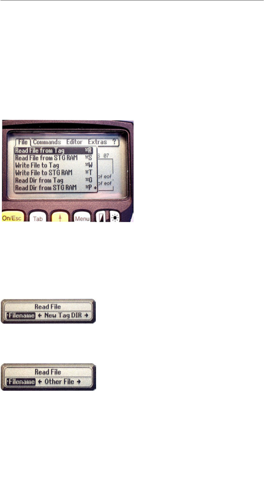
A 01.04
D-41
Handterminal STG
(5)J31069-D0126-U001-A5.1-7418
5.4 Die Datei-Funktionen
Im Datei-Menü können im wesentlichen drei Funktionen aufgerufen werden:
SDatei lesen
SDatei schreiben
SDirectory lesen und anzeigen
Diese Funktionen können sowohl auf dem MDS als auch auf dem internen
Speicher des Handterminals ausgeführt werden.
5.4.1 Lese Datei vom MDS
Nach dem Aufruf dieser Funktion erscheint ein Auswahlmenü, in dem Sie mit
den Cursortasten eine Datei auswählen können. Es werden dabei alle Filena-
men durchgeblättert, die auch in der Directory-Ansicht (siehe Kap. 5.3.2) zu se-
hen sind.
Nachdem Sie alle Dateien durchgeblättert ha-
ben, erscheint der Dateiname “Neues MDS
DIR”. Drücken Sie jetzt die Enter-Taste, so
liest der Filehandler eine Directory von einem
MDS ein.
Anschließend kann eine der neuen Dateien
selektiert werden.
Blättern Sie in dem Dateiauswahlmenü wei-
ter, bis der Dateiname “Andere Datei” er-
scheint, so können Sie im folgenden Menü
einen Dateinamen über die ASCII-Tastatur
des Handterminals eingeben.
Das Programm “FILEHANDLER”
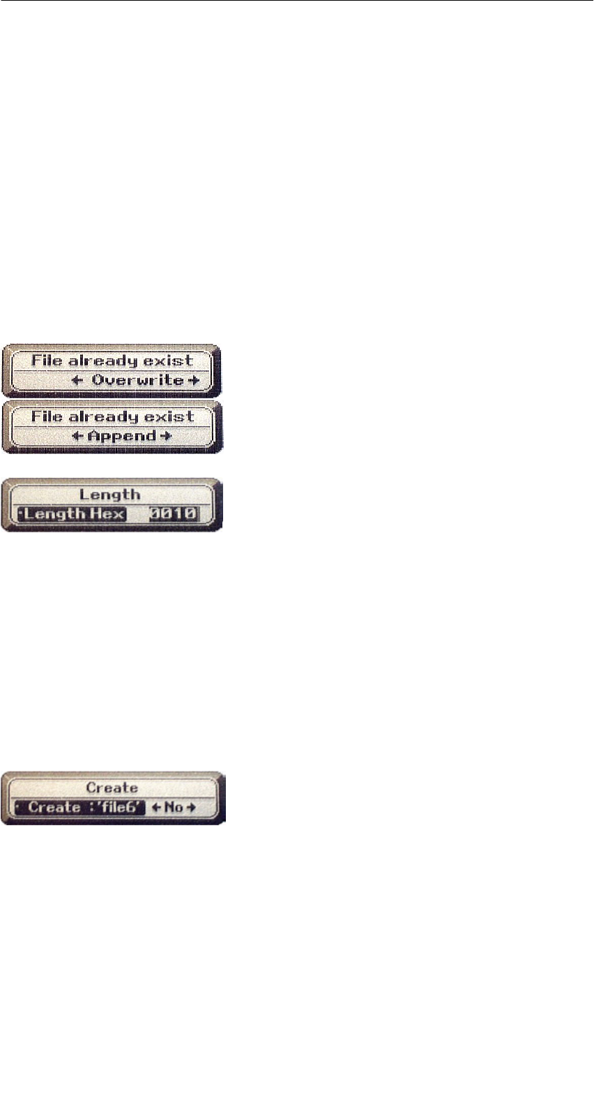
A 01.04
D-42 Handterminal STG
(5)J31069-D0126-U001-A5.1-7418
5.4.2 Lese Datei vom STG RAM
Nach dem Aufruf dieser Funktion erscheint ein Auswahlmenü, in dem Sie mit
den Cursortasten eine Datei auswählen können. Es werden alle Dateinamen
mit der Dateiendung .HEX angezeigt, die sich im RAM des Handterminals be-
finden. Befindet sich keine Datei mit der Endung .HEX im STG-RAM, so erhal-
ten Sie die Meldung “keine Datei vorhanden”.
5.4.3 Schreibe Datei auf MDS
Die Eingabe des Dateinamens erfolgt nach der gleichen Art und Weise, wie im
Kap. 5.4.1 beschrieben. Nach der Eingabe eines in der Directory vorhandenen
Dateinamens, erhalten Sie eine Auswahl:
Sie können die Datei überschreiben oder die
neuen Daten an die bestehende Datei anhän-
gen.
Beim Folgefenster können Sie die Länge der
zu schreibenden Daten noch verändern.
Als Defaultlänge wird immer der Wert ange-
zeigt, der auch die Länge der Daten im Editor
darstellt. Verändern Sie die Default-Längen-
angabe, so wird auch die Dateilänge auf dem
MDS angepasst.
Haben Sie Daten “Anhaengen” ausgewählt, so wird nach der Ausführung der
Schreibfunktion automatisch die Datei nochmal gelesen. Damit erhalten Sie die
gesamte aktualisierte Datei in den Editor.
Haben Sie beim Aufruf der Schreibfunktion den Dateinamen “Andere Datei” ge-
wählt und einen neuen Dateinamen über die Tastatur eingegeben, so erscheint
das Fenster “Neu”:
Bestätigen Sie dieses Fenster mit “Ja”, so
wird ein neues File auf dem MDS angelegt,
bevor die Daten auf den MDS geschrieben
werden.
Das Programm “FILEHANDLER”

A 01.04
D-43
Handterminal STG
(5)J31069-D0126-U001-A5.1-7418
5.4.4 Schreibe Datei auf STG RAM
Beim Speichern einer Datei wird der Dateiname, der im Editor angezeigt wird,
als Default angezeigt. Den Dateinamen können Sie vor dem Abspeichern noch
verändern. Der Filename kann aus bis zu 8 Zeichen bestehen. Beim Abspei-
chern wird dem Filenamen automatisch die Dateiendung .HEX angefügt.
5.4.5 Lese Verzeichnis vom MDS
Es wird das Dateiverzeichnis von einem MDS gelesen und in der Directory-An-
sicht auf dem Display dargestellt (siehe Kap. 5.3.2). Je nach MDS-Typ kann
dieser Vorgang einige Sekunden dauern.
5.4.6 Lese Verzeichnis vom STG RAM
Es wird das Dateiverzeichnis vom RAM des Handterminals (Laufwerk M:) aus-
gelesen und in der Directory-Ansicht auf dem Display dargestellt (siehe
Kap. 5.3.2). Im Display werden nur Dateien vom Typ *.HEX angezeigt. Ebenso
werden nur Dateien angezeigt und verwaltet, die sich in der Root-Directory des
Handterminal-RAM befinden.
Das Programm “FILEHANDLER”
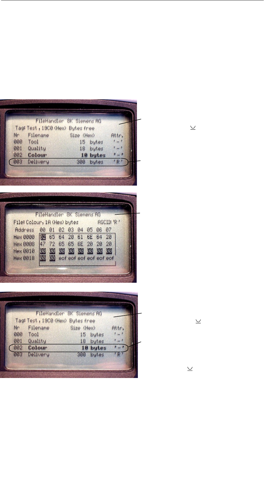
A 01.04
D-44 Handterminal STG
(5)J31069-D0126-U001-A5.1-7418
5.4.7 Beispiel: Kopieren von Dateien
Die in diesem Kapitel beschriebenen Funktionen ermöglichen ein sehr einfa-
ches Kopieren von Dateien. Dabei kann das Kopieren von MDS nach MDS
oder von STG RAM nach MDS geschehen. Im Folgenden ist der Ablauf be-
schrieben, wenn eine Datei von einem ersten MDS nach einem zweiten MDS
kopiert werden soll:
1. Die Funktion “Datei/Lese Verzeichnis
vom MDS” ( + G) ausführen
4. Die Funktion “Editor/Anzeige
Verzeichnis” ( + Q) ausführen
5. Mit den Cursor-Tasten " # die zu
schreibende Datei auswählen
6. Die Funktion “Datei/Schreibe Datei
auf MDS” ( + W) ausführen
Nach Ausführung dieser Funktionen
sind die Daten der Datei “Delivery” nach
“Colour” kopiert. Die Datei Colour er-
scheint jetzt ebenfalls mit einer Datei-
größe von 300 Byte.
3. “Enter” drücken; der Lesebefehl wird
gestartet. Nach dem Lesen werden
die Daten im Editorfenster angezeigt
2. Mit den Cursor-Tasten " # die
zu lesende Datei auswählen
Das Programm “FILEHANDLER”

A 01.04
D-45
Handterminal STG
(5)J31069-D0126-U001-A5.1-7418
5.5 Das Befehle-Menü
Im Befehle-Menü finden Sie Befehle, die
sich ausschließlich auf den MDS-Spei-
cher beziehen.
5.5.1 Datei neu
Mit “Datei neu” legen Sie eine neue Datei auf dem MDS an. Der Dateiname
darf auf dem MDS noch nicht vorhanden sein. Die neue Datei wird immer mit
der Länge “0” angelegt.
5.5.2 Datei loeschen
Diese Funktion löscht eine Datei auf dem MDS-Speicher.
Befinden Sie sich in der Directory-Ansicht, so können Sie die Löschfunktion
sehr einfach durch Drücken der “Del”-Taste starten. Mit der “Del”-Taste können
Dateien vom MDS oder vom Handterminal gelöscht werden. Vom Handterminal
werden die Dateien gelöscht, wenn die Directory-Ansicht die Dateien auf dem
STG anzeigt.
5.5.3 MDS formatieren
Bevor ein MDS mit dem Filehandler betrieben werden kann, muss dieser for-
matiert werden. Vor dem Formatieren ist es wichtig, die Speichergröße des
MDS richtig einzustellen. Verwenden Sie hierzu die Funktion Extras/Parameter.
Das Formatieren löscht alle Daten auf dem MDS. Die Dateistruktur wird neu
angelegt.
Das Programm “FILEHANDLER”

A 01.04
D-46 Handterminal STG
(5)J31069-D0126-U001-A5.1-7418
5.5.4 Datei Attribut
Mit diesem Befehl können auf einzelne Dateien Zugriffsrechte vergeben wer-
den. Damit sind die Dateien vor unberechtigtem bzw. unbeabsichtigtem Über-
schreiben geschützt. In der Directory-Ansicht wird das Dateiattribut in der rech-
ten Spalte angezeigt (siehe Kap. 5.3.2). Folgende Dateiattribute sind möglich:
Attribut Beschreibung
–kein Attribut bzw. ein bestehendes Attribut wird damit gelöscht.
RRead only; die Datei kann nur gelesen werden. Beschreiben, Über-
schreiben oder Löschen sind nicht möglich.
WWrite once; Die Datei kann einmalig beschrieben werden. Ein wieder-
holtes Beschreiben oder Löschen ist nicht möglich.
FFeste Länge; die Datei kann beliebig gelesen werden. Das Schreiben
ist nur zulässig, wenn die Länge der Datei nicht verändert wird. An-
hängen von Daten bzw. Löschen der Datei ist nicht möglich.
F/R Feste Länge und Read only ist gesetzt. Dieses Attribut hat die gleiche
Wirkung wie das “R”-Attribut.
Dateiattribute können nur auf MDS-Dateien vergeben werden. Dateien im RAM
des Handterminals sind immer vom Typ “–”. D. h., sie können generell verän-
dert oder gelöscht werden.
Das Programm “FILEHANDLER”
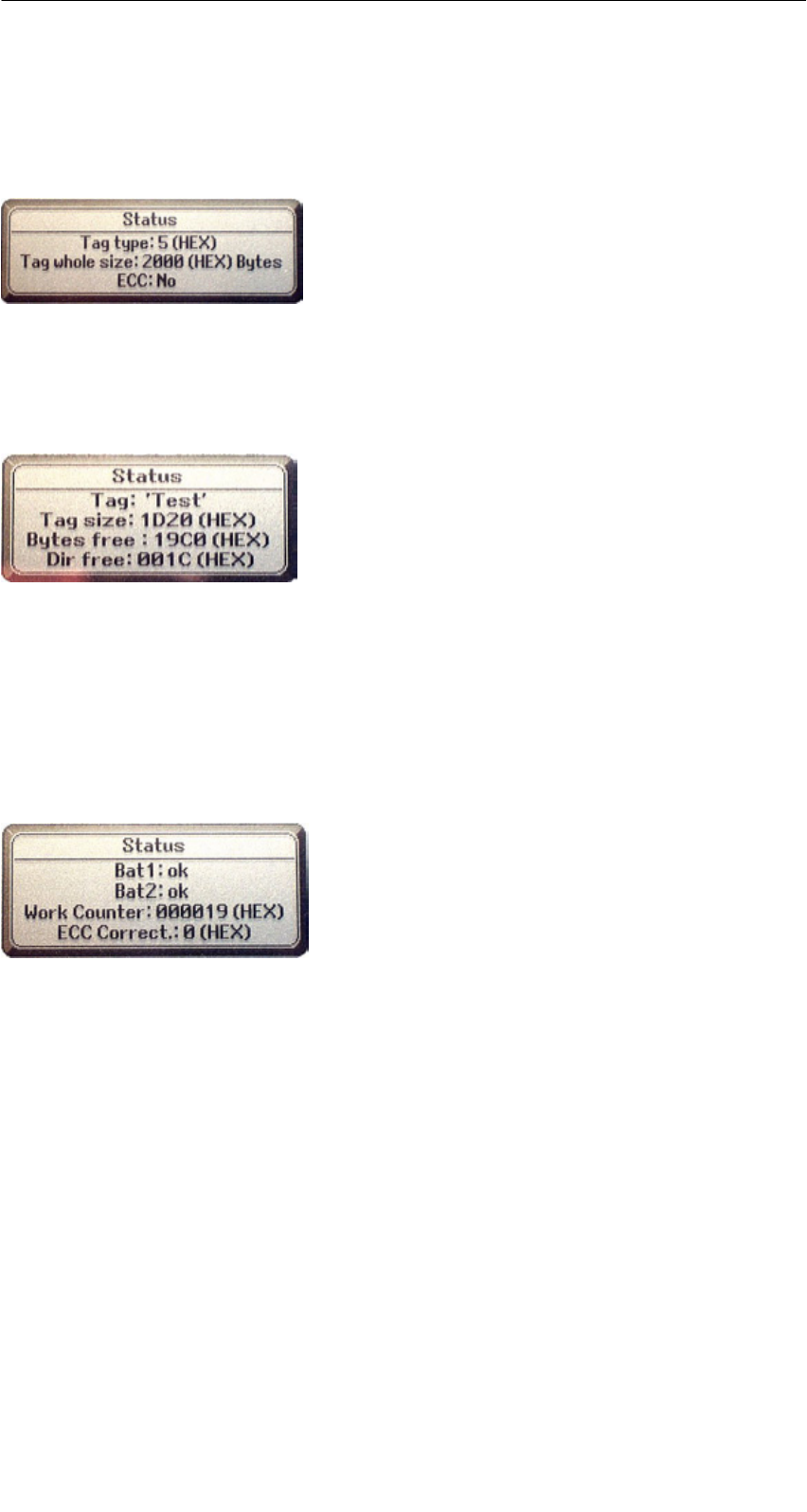
A 01.04
D-47
Handterminal STG
(5)J31069-D0126-U001-A5.1-7418
5.5.5 MDS Status
Dieser Befehl zeigt nacheinander in einigen Fenstern den Status des MDS an.
MDS-Typ:
Dieser Wert ist identisch mit der Angabe des
MDS-Typs beim Format-Befehl in einer SIMATIC.
BruttoMDS Groesse:
Hier wird die MDS-Grösse angezeigt, die beim
Format-Befehl eingestellt war.
ECC:
Zeigt an, ob der MDS mit oder ohne ECC betrie-
ben wird.
MDS:
Zeigt den Namen des MDS an, der beim Format-
Befehl auf den MDS geschrieben wurde.
MDS Groesse:
Zeigt den maximal für den Anwender nutzbaren
Speicherbereich an.
Bytes frei:
Zeigt die Anzahl der Datenbytes an, die auf dem
MDS dem Anwender für seine Daten noch zur
Verfügung stehen.
Dir frei:
Zeigt die Anzahl der Dateien an, die noch auf dem
MDS angelegt werden können.
Bat 1:
Zustand der RAM-Batterie. Dieser Wert ist bei
EEPROM-MDS nicht relevant.
Bat 2:
Zustand der Dialogbatterie beim MDS 507.
Bearb.-anzahl:
Anzahl der Bearbeitungen, die mit dem MDS seit
dem ersten Formatieren durchgeführt wurden. Der
Wert ist vor allem bei EEPROM-MDS wichtig, da
diese Speichertypen nur eine begrenzte Schreib-
häufigkeit besitzen.
ECC-Korrekt:
Zähler für die Anzahl der durchgeführten ECC-
Korrekturen. Hat dieser Zähler einen Wert un-
gleich Null, so ist der MDS demnächst auszutau-
schen. Ein EEPROM Speicher wurde zu häufig
beschrieben.
Das Programm “FILEHANDLER”
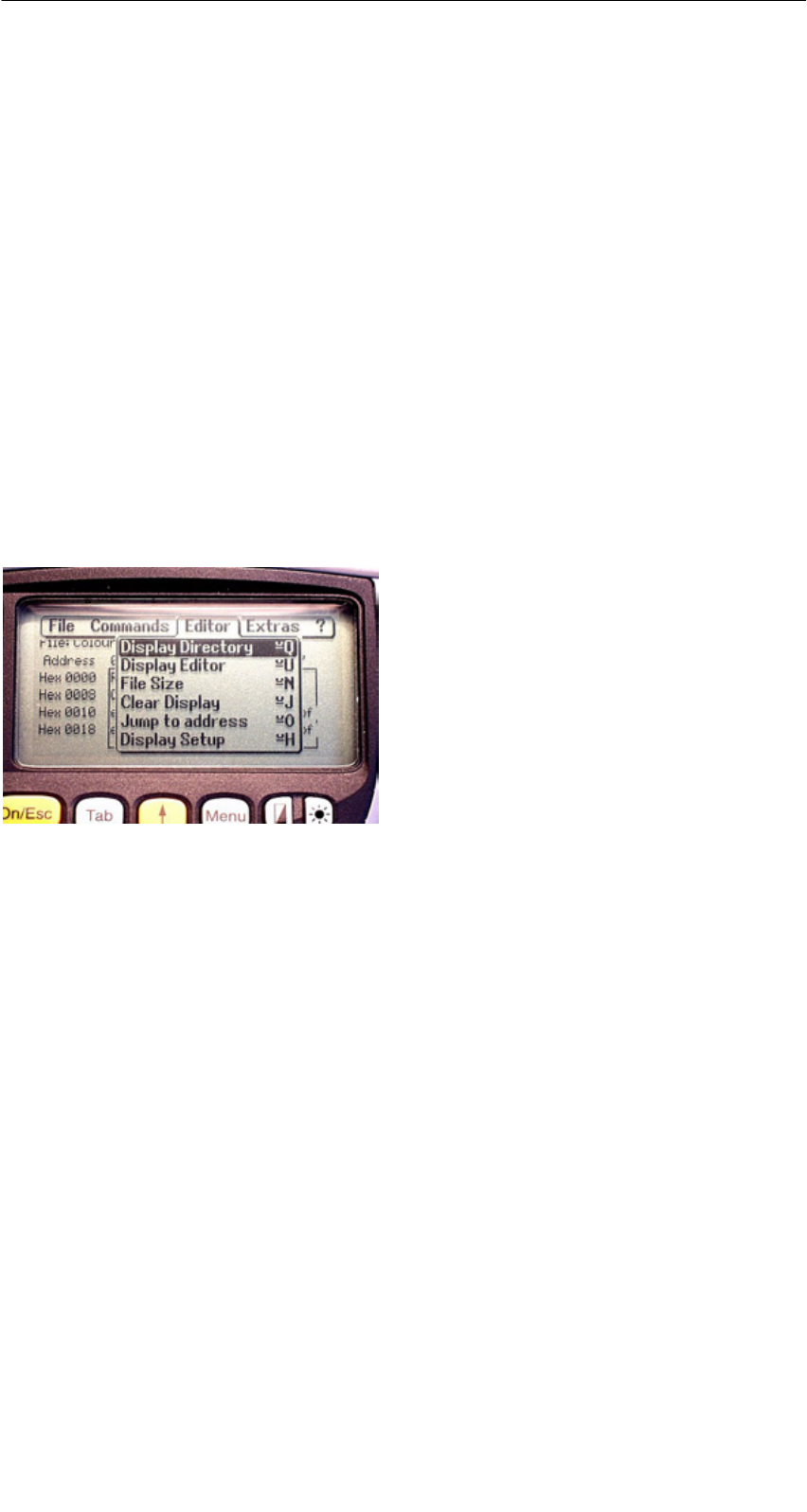
A 01.04
D-48 Handterminal STG
(5)J31069-D0126-U001-A5.1-7418
5.5.6 MDS Cover
Der Cover-Befehl verschließt die komplette Dateistruktur auf dem MDS. Ist ein
MDS “covered”, so kann
Sjede Datei gelesen werden
Sjede Datei beschrieben werden, solange die Dateilänge nicht verändert wird
Skeine Datei gelöscht werden
Skein neues File angelegt werden
Smit Format der MDS neu initialisiert werden. Danach ist der MDS “uncove-
red”.
Smit einem Cover-Befehl und der Einstellung “nicht covered” der Cover-Zu-
stand wieder aufgehoben werden.
5.6 Die Funktionen Editor
5.6.1 Anzeige Verzeichnis
Diese Funktion schaltet das Display um in die Directory-Ansicht (siehe
Kap. 5.3.2). Dargestellt wird das zuletzt gelesene Directory. Das Directory kann
sowohl vom MDS als auch vom Handterminal sein.
5.6.2 Anzeige Editor
Diese Funktion schaltet das Display um in die Editor-Ansicht (siehe Kap. 5.3.1).
Es wird die Datei angezeigt, die zuletzt eingelesen wurde. Diese Datei kann so-
wohl vom MDS als auch vom Handterminal sein.
Das Programm “FILEHANDLER”

A 01.04
D-49
Handterminal STG
(5)J31069-D0126-U001-A5.1-7418
5.6.3 Datei Größe verändern
Die momentane Länge einer Datei wird im Editor in der zweiten Zeile darge-
stellt. Diese Länge kann mit dem Befehl “Datei Größe” verändert werden. Wird
die Datei verlängert, so wird eine entsprechende Anzahl von Nullen (00 Hex)
am Ende der Datei angehängt. Der angehängte Teil wird im Editor mit invertier-
ten Ziffern dargestellt.
5.6.4 Anzeige löschen
Diese Funktion löscht den Speicher in der Editoranzeige. Dabei kann der hexa-
dezimale Wert des Füllzeichens vorgegeben werden. Der Standardwert des
Füllzeichens ist 00hex. Nach dem Löschen werden alle Daten in der Anzeige
invertiert dargestellt, um zu kennzeichnen, dass noch keine Daten vom Anwen-
der eingegeben wurden.
5.6.5 Sprung an Adresse
Die normale Positionierung des Cursors innerhalb einer Datei erfolgt mit den
vier Pfeiltasten (z, !, ", #). Bei größeren Dateien kann die Funktion “Sprung
an Adresse” sehr vorteilhaft eingesetzt werden, um den Cursor an eine belie-
bige Stelle innerhalb der Datei zu positionieren. Die Funktion “Sprung an
Adresse” kann sehr einfach auch über die Tab-Taste aufgerufen werden.
5.6.6 Anzeige Setup
Hier erfolgt die Einstellung der Anzeige. Die Darstellung kann im Hexadezimal-
oder ASCII-Format erfolgen. In der ASCII-Darstellung werden nicht darstellbare
Zeichen als weiße Felder angezeigt. Siehe hierzu ASCII-Tabelle im Anhang A.3.
Das Programm “FILEHANDLER”
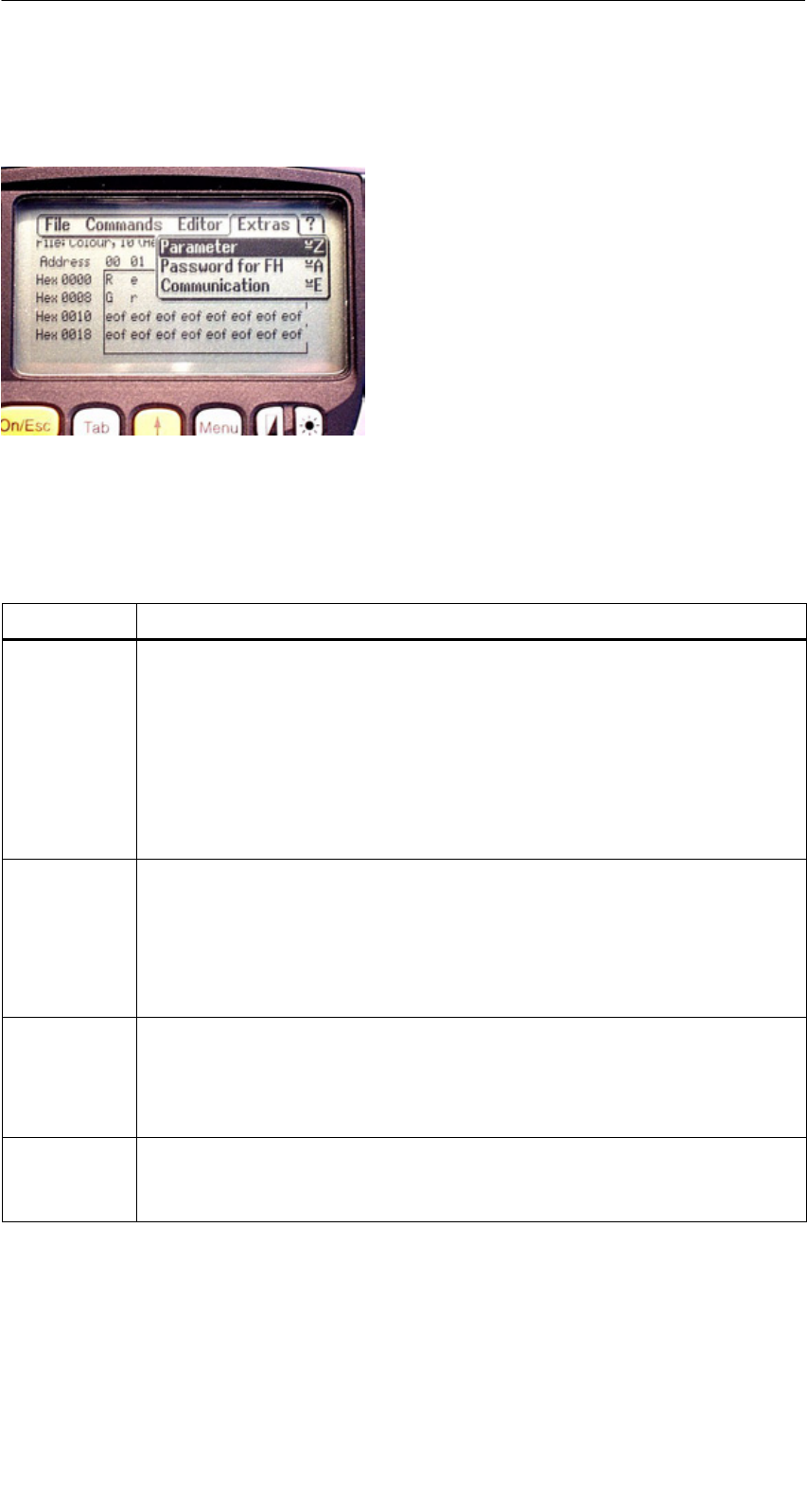
A 01.04
D-50 Handterminal STG
(5)J31069-D0126-U001-A5.1-7418
5.7 Die Funktionen Extras
5.7.1 Parameter
Mit der Funktion Parameter werden grundlegende Einstellungen für den Betrieb
des Filehandlers vorgenommen.
Parameter Beschreibung
MDS Größe Hier wird die Brutto-Speichergröße des MDS eingestellt, mit dem ge-
arbeitet werden soll.
Die eingestellte Speichergröße wird in der Anzeige in der ersten Zeile
angezeigt. Der Format-Befehl verwendet die Speichergröße für die
Festlegung des Dateisystems. Stimmt der Parameter “MDS Größe”
nicht mit dem benutzten MDS überein, so kann trotzdem mit dem
MDS gearbeitet werden. Nur der Format-Befehl würde dann zu einem
falschen Ergebnis führen.
MDS Typ Hier kann umgeschaltet werden zwischen RAM, EEPROM und
MDS 507. FRAM-Speicher werden behandelt wie RAM-Speicher. In
der Einstellung EEPROM wird die Batterie-Fehlermeldung in der An-
zeige unterdrückt, da diese MDS generell keine Batterie besitzen. In
der Einstellung MDS 507 wird auch die Dialogbatterie ausgewertet
und zur Anzeige gebracht, wenn sie entladen ist.
ECC
SLG Nr. Hex
Ein-/Ausschalten des ECC-Treibers
Die hier eingestellte SLG Nr. wird beim Bearbeiten eine MDS in den
Systembereich des MDS geschrieben. Sie hat primär keine Wirkung
auf die Funktion des Programmes Filehandler im STG.
EAKO Die Ein-/Auslaufkontrolle (EAKO) kann beim Filehandler im STG nicht
eingestellt werden. Das STG arbeitet generell ohne Ein-/Auslauf-
steuerung (EAKO = “4”)
Das Programm “FILEHANDLER”

A 01.04
D-51
Handterminal STG
(5)J31069-D0126-U001-A5.1-7418
5.7.2 Passwort für Filehandler
Das Passwort für Filehandler schützt den Anwender davor, dass unberechtigte
Benutzer des STG Daten auf dem MDS manipulieren können. Die Passwörter
für die Programme “Filehandler” und “MOBY D/E/F/I/U” sind identisch. Be-
schreibung zur Handhabung des Passworts siehe in Kap. 4.5.2.
5.7.3 Kommunikation
Die Kommunikation des Filehandlers ist grundsätzlich auf den “Lesekopf” ein-
gestellt. Optional kann der Filehandler auf “ASM an RS232” umgestellt werden.
Damit kann eine Baugruppe vom Typ ASM420-RS232 an das Handterminal an-
geschlossen werden. Weitere Hinweise finden Sie im Kap. 6.6.
Bitte beachten Sie, dass eine Baugruppe vom Typ ASM 421 nicht am STG be-
trieben werden kann.
5.8 Die Funktionen “?”
Die hier aufgeführten Funktionen sind identisch mit den Programmen
MOBY D/E/F/I/U. Siehe hierzu Kap. 4.6.
Das Programm “FILEHANDLER”

A 01.04
D-52 Handterminal STG
(5)J31069-D0126-U001-A5.1-7418
6 Erweiterte Funktionen
6.1 Die Hinterlegung der MDS-Daten im
Handterminal
Die vom MDS gelesenen Daten werden auf dem Handterminal automatisch in
einer Datei mit dem Namen “READ_D.HEX”, “READ_E.HEX”, “READ_F.HEX”,
“READ_I.HEX” oder “READ_U.HEX” im Laufwerk “RAMDRIVE” des PSION hin-
terlegt. Jeder weitere Lesebefehl überschreibt diese Datei.
Beim Beschreiben des MDS werden die Schreibdaten aus dem Editor auf den
MDS geschrieben und außerdem unter dem Namen “WRITE_D.HEX”,
“WRITE_E.HEX”, “WRITE_F.HEX”, “WRITE_I.HEX” oder “WRITE_U.HEX” auf
das Laufwerk RAMDRIVE (M:) des PSION gespeichert. Jeder weitere Schreib-
befehl überschreibt diese Datei.
Die Funktion “Datei/Laden Datei” zeigt alle Dateien mit der Dateiendung “.HEX”
an. Sie können eine davon mit den Cursor-Tasten auswählen. Diese Datei wird
dann in den Editor geladen. Es erfolgt dabei keine Abspeicherung mit dem
Namen READ_x.HEX bzw. WRITE_x.HEX.
Die Funktion “Datei/Speichern” speichert die Daten vom Editor in eine Datei mit
der Dateiendung “.HEX” und zugleich die ID-Nummer in eine Datei mit der
Dateiendung “.HX1” auf das RAMDRIVE-Laufwerk des PSION (Laufwerk M:).
Sie können einen beliebigen Namen mit 1 bis 8 alphanumerischen Zeichen ein-
geben.
Hinweis
Wenn Sie Daten vom MDS lesen, im Editor modifizieren und dann
abspeichern, werden die modifizierten Daten auf die .HEX-Datei ge-
speichert.
Erweiterte Funktionen
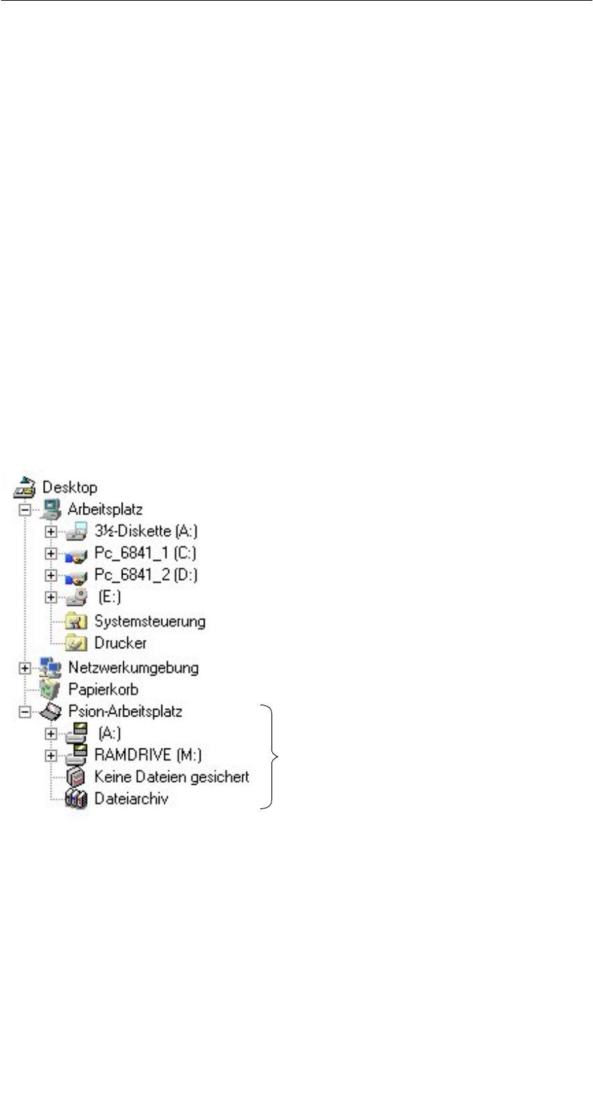
A 01.04
D-53
Handterminal STG
(5)J31069-D0126-U001-A5.1-7418
6.2 Kopieren von MOBY-Daten von und zum
Handterminal
6.2.1 Was wird zusätzlich benötigt?
SDas Programm PsiWin. Das ist ein Dateimanager von der Fa. PSION für das
Handterminal PSION Workabout.
SEin 3link Interface mit dem dazugehörigen Kabel zum Verbinden des PC mit
dem PSION Workabout.
Diese Komponenten können direkt von PSION bestellt werden (siehe An-
hang A.1).
6.2.2 Das Arbeiten mit dem PSION-Dateimanager
Der PSION-Dateimanager wird bei der Installation in den Windows-Explorer Ih-
res PC installiert. Nach der Installation besitzt Ihr Explorer weitere Laufwerke.
Im folgenden Bild ist das beispielhaft dargestellt. Sie können jetzt sehr einfach
in der vom Explorer gewohnten Weise Daten und Programme kopieren.
Der “Psion-Arbeitsplatz”
wird bei der Installation von PsiWin
neu im Explorer eingerichtet.
Bevor Sie den Psion-Arbeitsplatz im Explorer öffnen können, muss das PSION
über das 3link Kabel und die Wandhalterung angeschlossen sein und die
Schnittstelle für die Kommunikation (Port C) freigegeben sein.
Erweiterte Funktionen

A 01.04
D-54 Handterminal STG
(5)J31069-D0126-U001-A5.1-7418
Vorgehensweise zur Freigabe von Port C:
SDas STG-Programm mit EXIT verlassen. Es
erscheint das PSION-Grundmenü.
SMenu-Taste: den Cursor auf “System screen”
stellen und mit “Enter” quittieren. Es erscheint
eine Windows-ähnliche Oberfläche.
SMenu-Taste: SPEC/REMOTE LINK aufrufen.
Es erscheint das Fenster “Remote link”.
SIn diesem Fenster folgende Einstellungen vor-
nehmen: Remote link = ON; Baudrate = 19200;
Port = C; Parameters = (nichts eingeben)
SBevor Sie mit “Enter” quittieren, müssen Sie
eine Verbindung zum PC über das in Kapi-
tel 6.2.1 beschriebene 3link Kabel hergestellt
haben. Ansonsten erhalten Sie die Meldung
“Device does not exist”.
Sollten Sie bei dieser Vorgehensweise eine falsche Eingabe gemacht haben
und nicht mehr weiterkommen, so führen Sie einen System-RESET nach Kapi-
tel 6.7 durch.
Taucht im Verzeichnis Psion-Arbeitsplatz des Explorers weiterhin die Meldung
“keine Verbindung” auf, so überprüfen Sie bitte das 3link Kabel zwischen Hand-
terminal und PC sowie die REMOTE-Einstellung auf dem Handterminal.
Öffnen Sie nun mit einem Doppelklick auf das Laufwerk “RAMDRIVE” die
Dateistruktur des Handterminals. Dort finden Sie u.a. die Datei
“READ_D/E/F/I/U.HEX” und die von Ihnen abgespeicherten Dateien mit der
Endung “.HEX”. Diese Dateien können Sie nun per Drag-and-Drop oder
Kopieren von dem PSION-Laufwerk auf das PC-Laufwerk übertragen.
Erweiterte Funktionen

A 01.04
D-55
Handterminal STG
(5)J31069-D0126-U001-A5.1-7418
Die Datei READ bzw. WRITE hat eine Länge entsprechend der Größe des ge-
lesenen MDS:
READ_D.HEX: 44 Byte bei I-Code1
112 Byte bei I-Code SLI
256 Byte bei Tag-it HF-I
1000 Byte bei my-d
READ_E.HEX: 768 Byte bei MOBY E(im Normalmodus)
1024 Byte bei MOBY E(nach dem Lesen der Rohdaten)
1024 Byte bei MOBY E(im SIM-Modus)
READ_F.HEX: 5 Byte bei MOBY F (nach dem Lesen eines F1xx MDS)
192 Byte bei MOBY F(nach dem Lesen eines F4xx MDS)
256 Byte bei MOBY F (nach dem Lesen der Rohdaten
eines F4xx MDS)
READ_I.HEX:
Setup-Einstellung ohne ECC mit ECC
62 Byte
128 Byte
2 KB
8 KB
32 KB
62
128
2045
8189
32765
42
112
1778
7154
28658
READ_U.HEX:
Setup-Einstellung
2 KB
32 KB
2048
32768
Der Inhalt der Datei kann nun mit einem entsprechenden Editor am PC ange-
zeigt und verändert werden:
Wenn vom MDS ASCII-Daten gelesen wurden:
Jeder Editor kann verwendet werden: NOTEPAD, WRITE, WORD usw.
Wenn binäre Daten mit dem MDS ausgetauscht werden:
Verwendung eines HEX-Editors. HEX-Editoren sind auf dem Shareware-
markt (z. B. Hedit usw.) oder auf dem professionellen Markt verfügbar
(z. B. “Codewright”).
Nach Beendigung Ihrer Sitzung mit PsiWin sollten Sie die Remote link-Verbin-
dung wieder unterbrechen.
Restart der STG-Anwendung: siehe Kapitel 6.7
Für eine erneute Sitzung mit PsiWin sollten Sie die STG-Anwendung beenden.
Erweiterte Funktionen

A 01.04
D-56 Handterminal STG
(5)J31069-D0126-U001-A5.1-7418
6.2.3 Die Organisation der Datei READ.HEX
In der Datei READ_x.HEX stehen nur die reinen Daten, die auch auf dem MDS
vorhanden sind. Die Länge der Datei ist identisch mit der Größe des MDS (in
Bytes).
6.2.4 Die Organisation der Datei READ.HX1
In der Datei READ_x.HX1 ist die ID-Nummer hinterlegt. Die Datei READ_x.HX1
wird nur bei MOBY D/E/F/U angelegt.
6.3 Funktionen mit dem PSION-Betriebssystem
Über den Menübefehl DATEI/BEENDEN gelangen Sie auf die Betriebssystem-
ebene des Handterminals. Im Folgenden sind einige Möglichkeiten aufgezeigt,
die mit dem PSION-Betriebssystem möglich sind:
SEinfaches Schreiben einer Batch-Datei, um MDS-Daten auf eine Memory-
Card (z. B. in Laufwerk B:) zu kopieren.
SErstellen und Abändern einer AUTOEXEC-Datei, um die Zeit für das auto-
matische Abschalten bzw. die Zeit für die Hintergrundbeleuchtung zu verän-
dern, um Batteriestrom zu sparen und damit die Betriebsdauer mit einer Ak-
kuladung zu verlängern. Die AUTOEXEC-Datei befindet sich im Verzeichnis
A:\BTF\Autoexec.btf
SEditieren der gelesenen MOBY-Daten mit dem PSION-Editor. Das ist jedoch
nur möglich, wenn die MDS-Daten im ASCII-Format vorliegen.
STabellenkalkulation
SRechner
SAusführen von DOS-Befehlen
Eine genaue Beschreibung der Betriebssystemfunktionen und Standardpro-
gramme entnehmen Sie dem Manual “PSION Workabout USER GUIDE”. Die-
ses kann von PSION bestellt werden (siehe Anhang A.1).
Erweiterte Funktionen
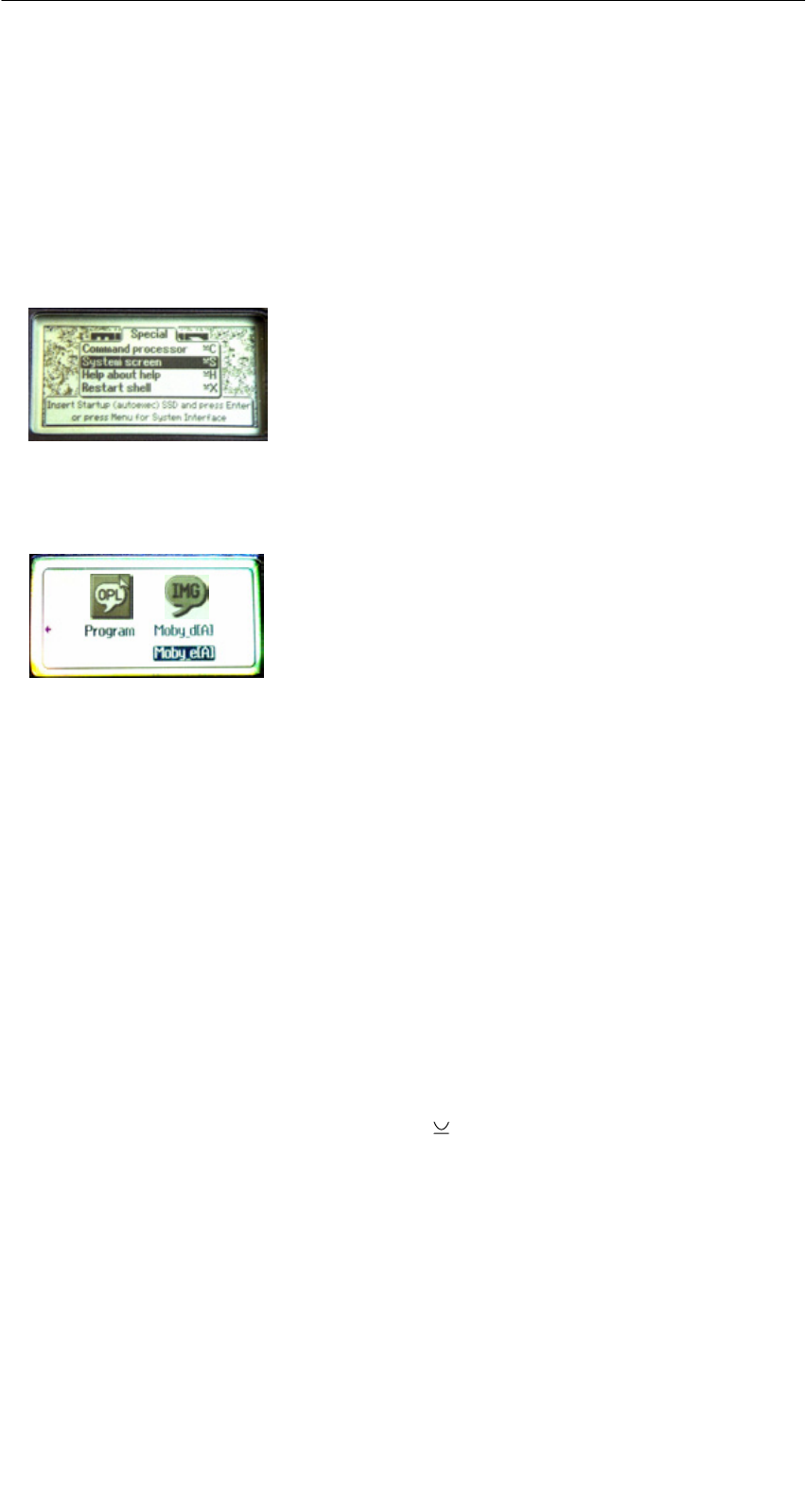
A 01.04
D-57
Handterminal STG
(5)J31069-D0126-U001-A5.1-7418
6.4 Paralleles Abarbeiten mehrerer Anwendungen
In der Windows-Ebene des PSION-Handterminals haben Sie die Möglichkeit,
mehrere Anwendungen gleichzeitig zu betreiben.
Gehen Sie hierzu wie folgt vor:
SVerlassen Sie das MOBY Service- und Testprogramm. Es erscheint die
PSION-Grundmaske:
SMenu → System screen
Sie gelangen in die Windows-Ebene des PSION. Es erscheinen mehrere
Icons auf dem Display:
SBewegen Sie den Cursor soweit nach rechts, bis die Anwendung “IMG” auf
dem Display erscheint.
SUnterhalb des Bildes IMG sehen Sie nun die Anwendungen, die Sie starten
können:
– MOBY D/E/F/I/U = MOBY Service- und Testprogramm für die jeweilige
MOBY-Familie
– FILEHAND = MOBY Filehandlerprogramm
– MENU = MOBY Programm Auswahlmenü
– (andere Kundenapplikationen; diese müssen im Verzeichnis IMG hinter-
legt sein; im Auslieferungszustand wird hier keine weitere Applikation an-
gezeigt)
SWählen Sie die Anwendung MOBY D/E/F/I/U über die Cursortasten aus und
drücken Sie Enter. Die bekannte MOBY STG-Anwendung wird gestartet.
SFühren Sie nun die Tastenkombination “ + TAB” aus. Am Display erscheint
wieder die PSION-Grundmaske.
SWählen Sie nun das nächste zu startende Programm auf dem Icon IMG oder
auf dem gesamten Windows-Bildschirm aus (z. B. den Taschenrechner
CALC) und starten Sie es mit Enter. Das neu gestartete Programm erscheint
am Bildschirm.
Erweiterte Funktionen
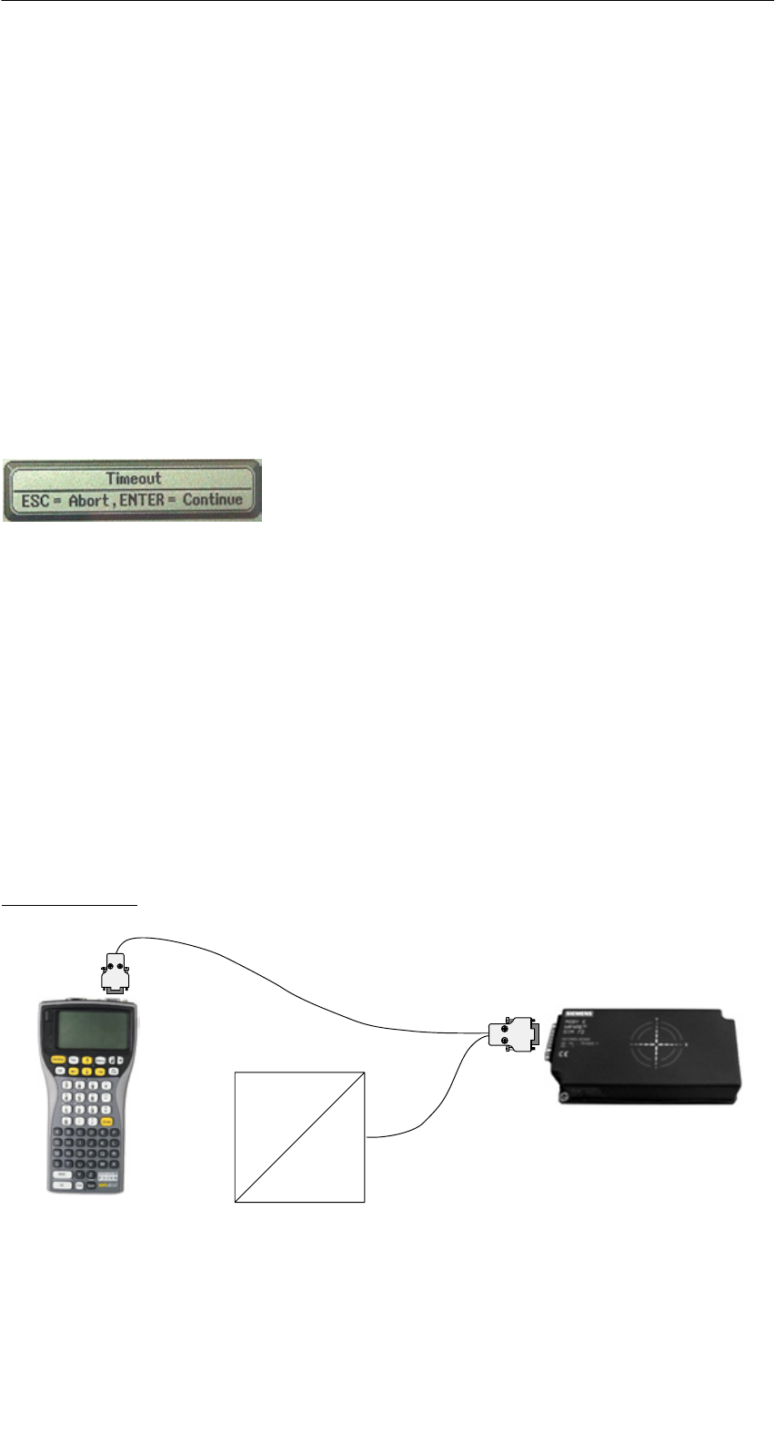
A 01.04
D-58 Handterminal STG
(5)J31069-D0126-U001-A5.1-7418
Mit diesem Verfahren können Sie neben der normalen Anwendung MOBY auch
Applikationen und PSION-Betriebsprogramme starten. Es laufen dann alle Pro-
gramme parallel auf dem Handterminal.
6.5 Die automatische Stromsparfunktion
Das PSION-Handterminal besitzt eine automatische Abschaltung. Diese wird
aktiviert, nachdem ca. 5 Minuten keine Taste am PSION betätigt wurde.
Darüberhinaus besitzen die Programme “MOBY D/E/F/I/U” eine weitere Strom-
sparfunktion. Wird 30 Sekunden nach Start eines MDS-Befehls kein MDS er-
kannt oder wird der in Bearbeitung befindliche MDS für länger als 30 Sekunden
aus dem Feld bewegt, so wird der laufende MDS-Befehl unterbrochen. Es er-
scheint folgende Meldung:
Sie können jetzt den Befehl mit ESC komplett
abbrechen oder mit ENTER fortsetzen. Beim
Fortsetzen wird der unterbrochene Befehl an der
Stelle fortgesetzt, an welcher er unterbrochen
wurde.
6.6 Anschluss von SIM-Geräten (MOBY E/I/V)
An der RS 232-Schnittstelle des PSION ist es möglich, ein MOBY E SIM anzu-
schließen. Das Anschlussschema kann dem folgenden Bild entnommen wer-
den. Mit der Funktion “Extras/KOMMUNIKATION/PROTOKOLL” muss vor der
Inbetriebnahme auf MOBY E/SIM oder ASM 420/I/V umgeschaltet werden.
In dieser Konfiguration kann sowohl mit dem “MOBY”-Programm als auch in
Anwenderapplikationen mit der MOBY-Library (vgl. Anhang A.2) mit dem SIM
gearbeitet werden.
MOBY E/SIM:
AC 220 V
DC 24 V
Kabel (6GT2 391-1DH50)
und
Netzteil (6GT2 090-0HB00)
Erweiterte Funktionen
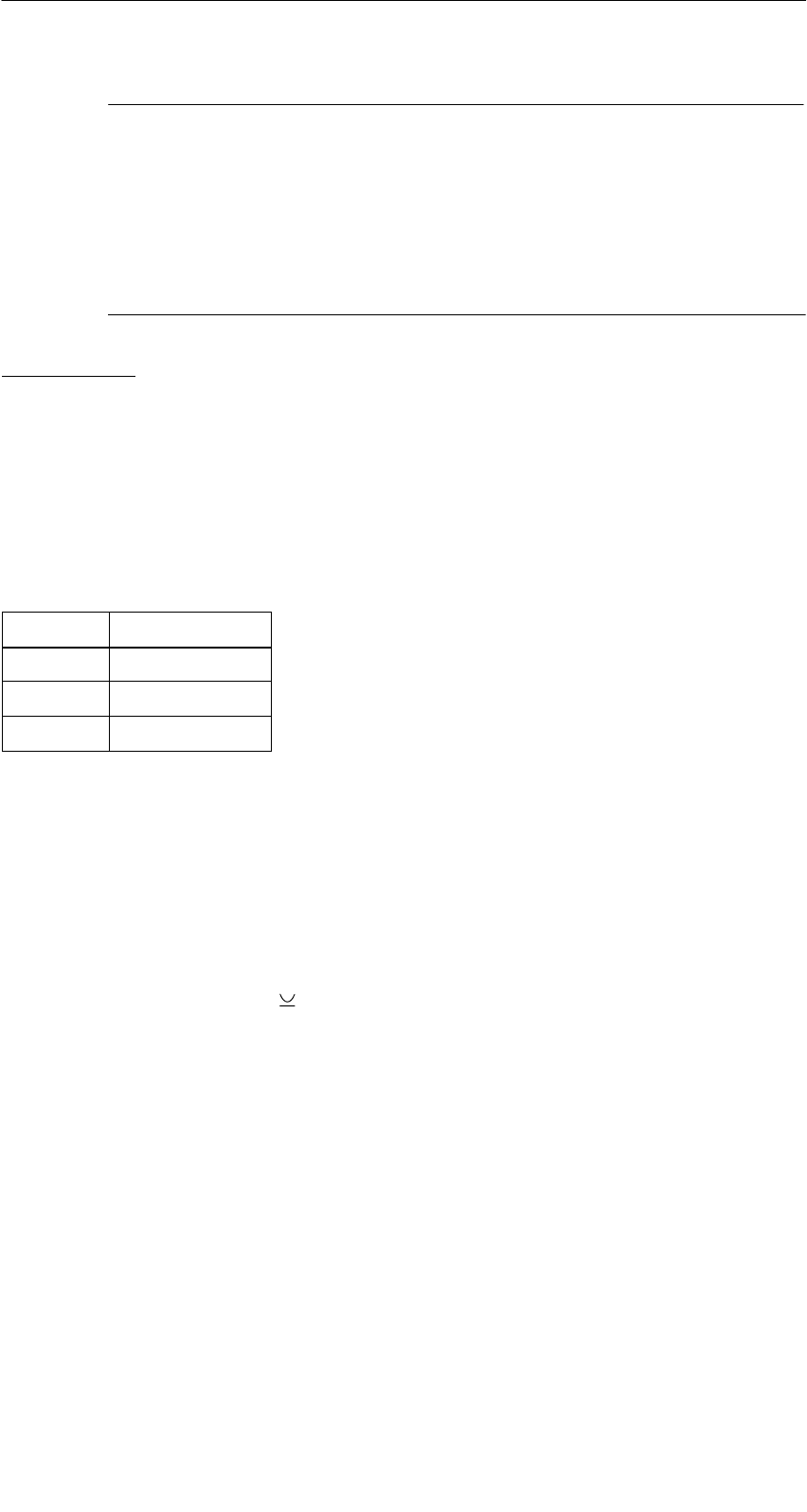
A 01.04
D-59
Handterminal STG
(5)J31069-D0126-U001-A5.1-7418
Hinweis
Das SIM arbeitet standardmäßig im zyklischen Betrieb. Deshalb
dauert die Abarbeitung eines Lese-/Schreibbefehls sehr viel länger
als beim STG-Lesekopf. Eine Umschaltung des SIM in den schnel-
len Lesemodus ist mit dem Befehl Extras/MOBY E Setup/FELDBE-
TRIEBSART möglich. Die Umschaltung des SIM muss nach jedem
Einschalten des SIM erfolgen.
ASM 420/I/V:
Bei dieser Einstellung kann ein ASM 420/RS232 an das Handterminal ange-
schlossen werden. Das Verbindungskabel muss entsprechend der
ASM 420-Dokumentation angefertigt werden. Beim Programm “MOBY I” wird
im ASM 420-Betrieb immer der MOBY V-Treiber eingeschaltet. Damit kann das
SLG 65 am ASM 420 betrieben werden. MOBY I-SLG können eingeschränkt
betrieben werden.
Belegung der RS 232-Schnittstelle am Handterminal:
Pin Benennung
2 TxD
3 RxD
5 Gnd
6.7 System-RESET
Einen System-RESET führt das Handterminal nach dem Einlegen der Batterien
beim ersten Einschalten durch. Dieser RESET ist einem Hardware-RESET
gleichzusetzen.
Ein System-RESET kann auch manuell herbeigeführt werden. Hierzu drücken
Sie gleichzeitig die Tasten “ + Ctrl + Del” (bzw. auf dem PSION mit numeri-
scher Tastatur die Tasten “Shift + Esc + Del”).
Beim System-RESET
Swird die MOBY STG-Anwendung neu gestartet,
Sbleiben gespeicherte Daten im Flash-Speicher immer erhalten (Laufwerk A:
oder B:),
Sbleiben die Daten im RAM-Speicher (Laufwerk “RAMDRIVE:”) erhalten. Sie
gehen jedoch verloren, wenn alle Batterien (inkl. Lithiumzelle) vom PSION
entfernt werden.
Erweiterte Funktionen

A 01.04
D-60 Handterminal STG
(5)J31069-D0126-U001-A5.1-7418
7 Die Programme “MOBY D/E/F/I/U” mit
numerischer PSION-Version
Das MOBY Service- und -Testprogramm funktioniert uneingeschränkt auch im
PSION Workabout mit numerischer Tastatur. Bei Applikationen, in denen nur
einfache und gleiche Anwendungen von nichtgeschultem Personal durchge-
führt werden, kann diese PSION-Variante vorteilhaft sein. Diese Handterminal-
Variante können Sie direkt von PSION beziehen (siehe Anhang A.1).
Vorteilhaft eingesetzt werden kann die Funktionalität der 4 Funktionstasten.
Folgende STG-Funktionen sind direkt auf einer Funktionstaste aufrufbar:
F1 = MDS lesen
F2 = MDS schreiben
F3 = Daten aus Datei laden
F4 = Daten in Datei abspeichern
Eine Eingabe von Daten ist nur mit den numerischen Tasten möglich.
Die Programme “MOBY D/E/F/I/U” mit numerischer PSION-Version

A 01.04
D-61
Handterminal STG
(5)J31069-D0126-U001-A5.1-7418
8 Fehlermeldungen
Was tun, wenn...
... beim MOBY Lesen/Schreiben die PSION-Anzeige erlischt?
SDie Batterien auf dem PSION sind leer. Gerät in die Ladeschale stecken
oder neue Batterien einsetzen.
SDer Akku-Pack wurde falsch in das Grundgerät eingesetzt (die Nase des
Akku-Packs muss sich auf der linken Seite befinden).
... am Display nach dem Einschalten nichts zu erkennen ist?
SDie Batterien sind leer.
SDer Kontrast des Displays ist verstellt. Zum Einstellen die Taste in der
obersten Reihe verwenden.
... Fehlermeldungen erscheinen, die nirgends definiert sind?
SEntfernen Sie beide Batterien aus dem Grundgerät und setzen Sie diese
nach 60 s wieder ein. Das Gerät hat jetzt den Auslieferungszustand. Tritt
der Fehler weiterhin auf, so hat das Gerät möglicherweise einen Defekt.
... beim Handterminal STG U die LED für Kommunikation rot leuchtet?
SDer Akku in der MOBY U-Antenne ist leer → Akku laden, siehe Kap. 3.4
... beim Handterminal STG U keine Kommunikation zwischen dem Grundgerät
und der Antenne zustande kommt (”Handshake-Timeout”)?
SDer Akku in der MOBY U-Antenne ist leer → Akku laden, siehe Kap. 3.4
SDie RS 232-Schnittstelle am Grundgerät auf feste Steckverbindung über-
prüfen.
... die Betriebsdauer der MOBY U-Antenne immer kürzer wird?
SEinen neuen Akku in die MOBY U-Antenne einsetzen.
Fehlermeldungen
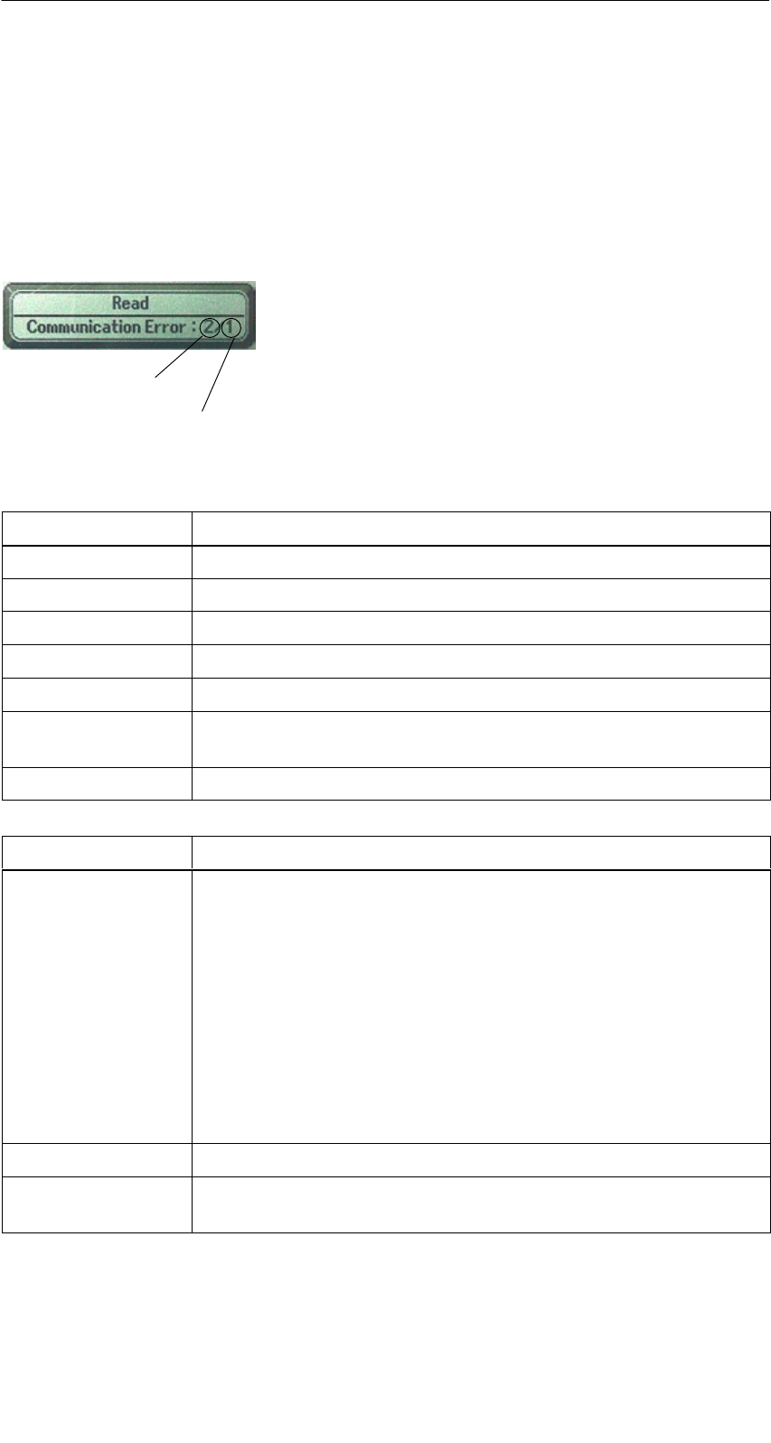
A 01.04
D-62 Handterminal STG
(5)J31069-D0126-U001-A5.1-7418
8.1 Fehlermeldungen bei den Programmen
“MOBY D/E/F/I/U”
Die Meldungen der folgenden Tabellen können beim Betrieb auftreten. Die An-
zeige erfolgt in einem eigenen Fenster. Eine Meldung kann folgende Form ha-
ben:
Die Meldung ist in mehreren Zahlen verschlüsselt.
Sie hat die Form xx/yy/zz und dient zur genauen
Fehleranalyse. In den folgenden Tabellen werden
die Fehlerarten und Fehlerbezeichnungen detailliert
aufgelistet. Die Information /zz kann bei einigen
Meldungen auftreten. zz beinhaltet weitere Fehler-
information (z. B. Block, bei welchem der Fehler
auftrat).
Fehlerart
genaue Fehlerbezeichnung
Fehlerart Beschreibung
1 bis 2 Allgemeine Fehler
3 bis 9 MOBY E-Fehler
10 bis 15 MOBY F-Fehler
20 Timer-Fehler
30 bis 37 MOBY I-Fehler
42 bis 45
52 bis 57
MOBY D-Fehler
MOBY D ISO-Fehler
60 bis 72 MOBY U-Fehler
Fehlerbezeichung Mögliche Fehlerursachen und deren Behebung
1, 2, 3, 4, 5, 6 SLesegerät sendet kein Startprotokoll
SLesekopf angeschraubt?
SPasst der Lesekopf zur Protokolleinstellung? (siehe Menü:
Extras/KOMMUNIKATION)
SAkkus im Lesegerät sind entladen (eventuell sind Akkus de-
fekt)
Sinterner Programmfehler
SDas Datum ist für die Funktion MDS-Status lesen nicht zu-
lässig (MOBY U: Fehlerbezeichnung = 3 bei Fehlerart = 64)
⇒Datum einstellen (siehe Kap. 4.2.5)
7Schnittstelle defekt
10, 11, 12 Lesegerät sendet keine oder eine fehlerhafte Antwort
(MDS D1xx/MDS F4xx)
Fehlermeldungen

A 01.04
D-63
Handterminal STG
(5)J31069-D0126-U001-A5.1-7418
Fehlerbezeichung Mögliche Fehlerursachen und deren Behebung
20 SLesegerät sendet keine Antwort
SParameter im Menü Extras/KOMMUNIKATION überprüfen.
Bei SIM-Betrieb muss bei “Schnittstelle” und “Protokoll” auf
SIM umgestellt werden.
SAkkus im Lesegerät sind entladen (eventuell sind Akkus de-
fekt)
21 Lesegerät sendet keine oder eine fehlerhafte Antwort
Sinterner Programmfehler (MDS D1xx)
22 bis 27 SLesegerät sendet falsche Antwort
SMDS ist nicht mit dem MOBY-Schlüssel personalisiert
Sinterner Programmfehler (MDS D1xx/MDS F4xx)
32 unzulässige Anforderung, interner Programmfehler
SKontakt zum Lesekopf überprüfen
SLesegerät sendet keine Antwort (MDS E6xx)
33, 34, 35, 36 interner Programmfehler
SSTG-Programm beenden und neu starten
SSchreib-/Lesefehler (MDS F4xx)
37 SLesekopf liefert eine Fehlermeldung
SLesekopf ist fehlerhaft
SCRC-Fehler vom MDS; Kommunikationsfehler zum MDS;
MDS im Grenzbereich
SMDS hat einen Defekt
Sinterner Programmfehler
38 angegebener Block ist schreibgeschützt
39 Mehrere MDS sind im Feld
Sinterner Programmfehler (MDS D1xx)
40, 41, 42 Lesegerät sendet keine oder eine fehlerhafte Antwort
(MDS D1xx/MDS F1xx/MDS Uxxx)
Sinterner Programmfehler (MDS D1xx)
SSchnittstelle zur MOBY U-Antenne überprüfen (MDS Uxxx)
43 Benutzerabbruch durch ESC
45 falsche Antwort des Lesegerätes
50 Fehler während Lesen bzw. Schreiben der MDS-Daten
52, 53, 54, 55,
56, 57
interner Programmfehler mit MOBY-Lesekopf
63 Authentifizierungsfehler; der MDS besitzt nicht den MOBY-
Schlüssel
SEventuell über “Extras/MOBY E Setup” den Schlüssel “B”
einstellen.
Fehlermeldungen

A 01.04
D-64 Handterminal STG
(5)J31069-D0126-U001-A5.1-7418
Fehlerbezeichung Mögliche Fehlerursachen und deren Behebung
65 Schnittstellenfehler; erscheint beim Anschluss eines SIM.
SParameter im Menü Extras/KOMMUNIKATION überprüfen
SStecker und Kabel zum SIM überprüfen
66 allgemeiner Lese-/Schreibfehler des MOBY-Lesekopfes
67 interner Programmfehler mit MOBY-Lesekopf
70 SSchreiben nicht erfolgreich
Smehrere Tags im Feld
80 MDS-Typ an Lesegerät wird nicht unterstützt
81, 82 SLesegerät sendet falsche Antwort
SMDS ist nicht mit dem MOBY-Schlüssel personalisiert
Sinterner Programmfehler (MDS Fxxx)
101 bis 132 Lesegerät sendet Fehler (MOBY I/U)
Spezifikation bestimmter Fehler:
101 Anwesenheitsfehler
SEs befindet sich kein MDS im Feld, der die im Befehl vorge-
gebene MDS-Identnummer besitzt.
103 Fehler in der Verbindung zum SLG
SDie Hardware des Lesekopfes hat einen Defekt
104 Fehler im Speicher des MDS
SINIT-Befehl durchführen; zuvor muss die Speichergröße des
MDS über “Extras/MOBY I Setup” richtig eingestellt werden.
SDer MDS ist defekt.
105 MOBY-Befehl vom Lesekopf/von der MOBY U-Antenne nicht
interpretierbar
SDie eingestellte Speichergröße über “Extras/MOBY I Setup”
oder “Extras/MOBY U Setup” überprüfen
106 SFeldstörung am Lesekopf: Externes Störfeld
SDer MDS hat während der Kommunikation das Feld verlas-
sen.
SFeldstörung während der Kommunikation
107 zu viele Sendefehler; der MDS konnte die Daten vom Lesekopf
nicht richtig empfangen.
SDas MDS steht im Grenzbereich des Lesekopfes
109 CRC-Fehler bei der Initialisierung des MDS durch Feldstörung.
110 MDS lässt sich nicht initialisieren und ist defekt.
Fehlermeldungen

A 01.04
D-65
Handterminal STG
(5)J31069-D0126-U001-A5.1-7418
Fehlerbezeichung Mögliche Fehlerursachen und deren Behebung
111 Timeout beim Initialisieren (MOBY I)
SDer MDS steht im Grenzbereich des Lesekopfes.
SEs wird ein MDS 507 initialisiert und der MDS507-Betrieb
über “Extras/MOBY I Setup” ist nicht eingeschaltet.
Der Speicher des MDS ist nicht korrekt lesbar (MOBY U).
112 SDer MDS-Speicher ist nicht beschreibbar und ist defekt.
SDas erneute Schreiben in den OTP-Speicher ist nicht zuläs-
sig.
113 Der Adressbereich des MDS wurde überschritten.
SDie eingestellte Speichergröße über “Extras/MOBY I Setup”
oder “Extras/MOBY U Setup” prüfen.
114 ECC-Fehler bzw. der MDS ist nicht im ECC-Modus initialisiert.
SÜber “Extras/MOBY I Setup” den ECC Betrieb einschalten
und anschließend den Init-Befehl durchführen.
115 Resetmeldung nach Spannungswiederkehr:
SHandterminal hat einen Defekt in der Spannungsversorgung
zum Lesekopf (evtl. Batterien aufladen/austauschen).
SDie Hardware des Lesekopfes hat einen Defekt.
125 interner Programmfehler: vorheriger Befehl aktiv
129 Die Anzahl der im Feld befindlichen MDS ist unzulässig. An-
zahl MDS > Multitag in der Funktion SLG-Status unter “Extras”.
130 interner Programmfehler; der Telegrammaufbau des Befehls
zum Lesekopf ist falsch
180 bis 243 interner Programmfehler (MDS D1xx)
Schalten Sie das Gerät aus und wieder ein. Bei wiederholtem
Auftreten des Fehlers melden Sie sich mit der Angabe der Feh-
lernummer beim Customer Support.
251 Schreib-/Lesevergleich war nicht erfolgreich
255 keine Karte/kein MDS im Feld
Fehlermeldungen

A 01.04
D-66 Handterminal STG
(5)J31069-D0126-U001-A5.1-7418
8.2 Fehlermeldungen beim Programm “FILE-
HANDLER”
Die Meldungen der folgenden Tabelle können beim Betrieb des Filehandlers
auftreten. Eine Filehandler-Fehlermeldung hat die folgende Form:
Der Filehandlerfehler wird in der gleichen Art und
Weise dargestellt wie auch beim Filehandler in
der SIMATIC. Es ist ein Alphazeichen, gefolgt vo
n
einer 3-stelligen Nummer. Die Fehlercodes sind
weitgehend identisch mit den Fehlernummern
aller MOBY-Filehandler-Anschaltungen.
Fehlerart
(siehe Kap. 8.1)
genauer Filehandlerfehler
Filehandler-
fehler
Fehlerbeschreibung, Ursache und Behebung Fehlerart
A006 Unbekannter Befehl, die Kommandokennung KK ist
nicht zulässig
A011 Beim 1. Befehlsblock DBN nicht 1; bei Folgeblock KK
oder DBN falsch Protokoll-
fhl
A015 Checkbyte-Error beim Empfang von S5 fehler
A016 Befehl vom anderen Absender in Bearbeitung
A020 falsche Anzahl von Zeichen im Telegramm
B001 Fehler in Verbindung zum SLG; Lesekopf defekt SLG-Fehler
C002 Fehler im RAM des MDS; MDS wechseln, FORMAT
durchführen
C006 Anwesenheitsfehler; MDS steht im Grenzbereich
C007 Parametrierfehler bei FORMAT; Befehl nicht interpre-
tierbar
C008 Zu viele Sync-Versuche; Feldstörung am Lesekopf
C009 Zu viele Sendefehler
C010 CRC-Sendefehler
MDS F hl
C011 FORMAT, CRC-Fehler beim Empfang MDS-Fehler
C012 FORMAT, MDS lässt sich nicht initialisieren
C013 FORMAT, Timeout; MDS steht im Grenzbereich
C014 FORMAT, not initialized; Extras/Parameter überprüfen
C015 CMD Adressfehler; Extras/Parameter überprüfen
C016 ECC-Fehler; MDS neu formatieren; ECC Betrieb ab-
schalten
C017 Allgemeiner Treiberfehler
Fehlermeldungen

A 01.04
D-67
Handterminal STG
(5)J31069-D0126-U001-A5.1-7418
Filehandler-
fehler
FehlerartFehlerbeschreibung, Ursache und Behebung
D001 Nur RESET-Befehl zulässig
D005 Unzulässige Parameter bei FORMAT, CREATE,
WRITE, UPDATE oder ATTRIB
D009 RESET-Befehlsparameter falsch
D014 CREATE und WRITE: Der Nutzdatenbereich auf dem
MDS ist voll belegt Auftrags-
bezogene
D015 Nur FORMAT-Befehl möglich; MDS nicht identifiziert
b
ezogene
F
e
hl
e
r
D018 Anfangsadresse im Befehl ist außerhalb des Datenbe-
reiches (Anfangsadresse > Dateilänge)
Fehler
D022 Directory und/oder FAT-verändernder Zugriff auf einen
mit COVER geschützten MDS unzulässig.
D023 COVER: MDS-Name falsch
E001 Der MDS-Typ ist falsch oder passt nicht zur eingestell-
ten Betriebsart (ECC).
E002 CREATE-Befehl: kein Directory-Eintrag mehr frei Directory-
bezogene
E003 CREATE-Befehl: Datei bereits im Directory vorhanden
b
ezogene
F
e
hl
e
r
E005 Bei READ oder WRITE wird ein FAT Blockfolgefehler
festgestellt, die FAT ist defekt
Fehler
F001 Die angesprochene Datei ist nicht vorhanden
Dateibezo
F005 WRITE/UPDATE/DELETE-Befehl auf eine Datei, die
mit entsprechendem Attribut geschützt ist
Dateibezo-
gene Fehler
H140 Serielle Schnittstellen Fehler
H141 Falsche Schnittstelle
H142 fehlerhafter Timer
H143 Schnittstellen-Fehler
H144 Startprotokoll Fehler
H145 Reset-Fehler, WRITE
Fehler
-
H146 Reset-Fehler, READ, kein STX
Fehler
-
meldun
g
der
H147 Reset-Fehler, READ, Timeout
meldung der
Filehandler-
A lik ti
H148 Reset-Fehler, READ, Falsche Antwort Applikation
H149 Start-Fehler, WRITE
H150 Start-Fehler, READ, kein STX
H151 Start-Fehler, READ, Timeout
H152 Start-Fehler, READ, Falsche Antwort
H153 Start-Fehler, WRITE, Länge zu groß
Fehlermeldungen

A 01.04
D-68 Handterminal STG
(5)J31069-D0126-U001-A5.1-7418
9 Technische Daten
Hardware
Prozessor NEC V30mx 27,68 MHz (80C86 kompatibel)
RAM-Speicher 2 MB; davon sind ca. 1,8 MB frei verwendbar
ROM-Speicher 2 MB für Betriebssystem
Anwender-
programm
1 MB (mit MOBY Service- und -Testprogramm)
Bildschirm Grafischer LCD-Bildschirm mit 240x100 Bildpunkten; Graustu-
fenskala; zuschaltbare Hintergrundbeleuchtung
Tastatur Alphanumerisch mit 57 Tasten
Sound Piezo-Signalgeber
Stromversorgung NiCd-Akku-Pack mit 2 Zellen vom Typ AA (1 Ah)
Schnellladefähig; automatische Abschaltung
Betriebsdauer: 20 Stunden
(Lesekopf inaktiv, Display unbeleuchtet)
4,5 Stunden 1
(Lesekopf aktiv, Display unbeleuchtet)
10 Stunden
(Lesekopf inaktiv, Display beleuchtet)
Backup-Batterie: 3 V Lithium-Zelle CR 1620
Schnittstellen LIF-Schnittstelle (Low Insertion Force Schnittstelle) für Batterie-
ladung und Kommunikation mit PC und Drucker (3link Kabel
nicht enthalten);
RS 232- und TTL-Schnittstelle zum Anschluss eines MOBY-Le-
sekopfes;
RS 232-Schnittstelle zum Anschluss einer MOBY U-Antenne
Sicherheit Verschlussmechanik für Batterie und Programmspeicher
Software
Betriebssystem EPOC/16 Multitasking, Grafikunterstützung, GUI-Schnittstelle;
MS-DOS ähnlicher Interpreter
Dateiverwaltung MS-DOS kompatibel
Integrierte
Software
MOBY Service- und Testprogramm; Tabellenkalkulation; Daten-
bank; Taschenrechner; Kommunikation
1 Gilt nicht für MOBY U, da die Antenne einen eigenen Akku hat. Betriebsdauer (Antenne
aktiv) siehe Technische Daten der MOBY U-Antenne.
Technische Daten

A 01.04
D-69
Handterminal STG
(5)J31069-D0126-U001-A5.1-7418
Technische
Daten
Komplettgerät
(inkl. Akkus)
Lesekopf/Antenne
Abmessungen 90 x 260 x 35 [mm]
(MOBY D/E/F/I)
90 x 64 x 35 [mm]
(MOBY D/E/F/I)
282 x 235 x 93 [mm] (MOBY U)
Gewicht ca. 480 g (MOBY D/E/F/I) ca. 100 g (MOBY D/E/F/I)
ca. 1450 g (MOBY U) ca. 1100 g (MOBY U)
Temperatur Betrieb: –20 °C bis +60 °C
Lagerung: –25 °C bis +70 °C (ohne Batterie)
Relative
Feuchtigkeit
0 % bis 90 % nicht kondensierend
Schutzart IP54 (spritzwassergeschützt) 2
Schlagfestigkeit Max. Fallhöhe auf Beton: 1 m (MOBY D/E/F/I)
0,5 m (MOBY U)
EMV EN 55022
Elektrostatik; RF;
EFT
IEC 801-2; IEC 801-3; IEC 801-4
2 Bei Handterminal STG U nur für Komplettgerät mit PSION Workabout
Technische Daten

A 01.04
D-70 Handterminal STG
(5)J31069-D0126-U001-A5.1-7418
RF-Schreib-/Lesekopf
MOBY D 13,56 MHz (I-Code; Tag-it)
max. Leseentfernung: 60 mm mit MDS D139
25mm mit MDS D160
Labels auf Basis I-Code in der Standardgröße
(ca. 85 x 55 mm):
max. Leseentfernung: 75 mm mit I-Code1
100mm mit I-Code SLI
100mm mit Tag-it HF-I
100mm mit my-d
Zulassungen: ETS 300 330
MOBY E 13,56 MHz (MIFARE)
max. Leseentfernung: 30mm mit MDS E611
18mm mit MDS E600
8mm mit MDS E624
4mm mit MDS E623
3mm mit MDS E623,
eingebaut in Metall
Zulassungen: ETS 300 330 Reg. Nr. G100213L
FCC ID: KR5MIS
MOBY F 125 kHz (HITAG)
max. Leseentfernung: 80mm mit MDS F125
50mm mit MDS F415
60mm mit MDS F124
Zulassungen: ETS 300 330 Reg. Nr. G100294L IF
MOBY I 1,81 MHz (Daten); 134 kHz (Energie)
MDS-Typ max. Leseentfernung (mm)
401/402
404/514/413E
403
506
439E
507 mit Batterie
507 ohne Batterie
6
20
8
12
12
35
4
Zulassungen: ETS 300 330 Reg. Nr. TTI-P-G 128/96
FCC ID: KR5MIS-I
Technische Daten

A 01.04
D-71
Handterminal STG
(5)J31069-D0126-U001-A5.1-7418
MOBY U-Antenne
Übertragungsfrequenz 2,4 bis 2,4835 GHz
Bandbreite 2 x 1 MHz innerhalb 83 MHz
Bruttobitrate des Funkkanals 384 kBit/s
Datenrate (Schreiben/Lesen)
(Netto)
ca. 8/4,8 KByte/s ohne Pulk
Antenne
SAbstrahlrichtung
SÖffnungswinkel
SPolarisation
SStrahlungsleistung
SStrahlungsdichte
senkrecht zur Rückseite der MOBY U-Antenne
ca. 90° (kegelförmiges Antennenfeld)
zirkular
< 50 mV/m in 3 m Abstand
< 0,5 µW/cm2 in 1 m Entfernung
Reichweite (Schreiben/Lesen)
SGrenzabstand (Sg)
Smax. / min. / Standard
SOrtsauflösung
0,15 m bis 3 m
entspricht eingestellter Reichweitenbegrenzung
3 m / 0,5 m / 1 m
über Reichweitenbegrenzung in Stufen von
0,5 m einstellbar
MDS-Erfassungszeit ca. 3 s bei 1 MDS
(nach Betätigung der Kommunikationstaste)
Stromversorgung Lithium-Ionen-Akku-Pack 2SIP CGR18650 HG
7,2 V 1,8 Ah
schnellladefähig, automatische Abschaltung,
Lebensdauer ca. 500 Ladezyklen
Stromaufnahme (Antenne ein) < 800 mA
Betriebsdauer 3> 2 Monate (Antenne nicht aktiv)
2 Stunden (Antenne aktiv)
Die Antenne wird über den Kommunikationsta-
ster nur für die Kommunikation eingeschaltet
und nach der Funktionsausführung automa-
tisch ausgeschaltet. Die kürzeste Einschalt-
dauer für einen Kommunikationsvorgang be-
trägt ca. 3 s (in Abhängigkeit vom Datenvolu-
men), wenn sich ein MDS im Feld befindet.
Betriebsarten
Soff
Ssearch
SCommunication
Antenne ausgeschaltet
bereit, vom MDS gesendete Search-Informa-
tion zu empfangen und auszuwerten
Kommunikation mit dem MDS: schreiben, lesen
oder initialisieren
Mindestabstand zu einem
SLG U92 oder einem anderen
STG U
≥ (eingestellte Reichweite + 0,5 m)
Technische Daten

A 01.04
D-72 Handterminal STG
(5)J31069-D0126-U001-A5.1-7418
Serielle Schnittstelle zum PSION
SÜbertragungsrate
SÜbertragungsprotokoll
RS 232
115,2 kBaud
3964R
Schnittstelle für Batterieladung
SSpannung / Strom
SLadedauer
4-polige Buchse für Anschluss des Netzteils
STG U
DC 12 V / 1,225 A
> 1,5 h (LiIon-Akku-Pack 2SIP CGR18650 HG)
Bedienelement Kommunikationstaste
(zum Auslösen der Kommunikation)
Anzeigeelemente
SLED für Laden der Akkus
– leuchtet
– leuchtet nicht
2 LED
Netzteil angeschlossen
rot: Gerät ist defekt
gelb: Akkus werden geladen
grün: Akkus sind geladen
Netzteil nicht angeschlossen
SLED für die Kommunikation
– leuchtet
– leuchtet nicht
Kommunikationstaste betätigt und Kommunika-
tion nicht beendet
rot: Batteriekapazität ist für die
Kommunikation nicht ausreichend
gelb: Antenne ist aktiv geschaltet
Bereit, einen MDS zu identifizieren
oder einen MDS zu identifizieren und
mit ihm zu kommunizieren.
Kommunikation beendet oder noch nicht ge-
startet
Gehäuse
SFarbe / Material schwarz / Polyamid 6 GF 30
Zulassungen RF: I-ETS 330440+C1:1997
SAR: 99/519/EG
Safety: EN 60950:2000
EMC: EN 301489-01:2000
EN 301489-03:2000
ENV 50204:1995
FCC ID: NXWMOBYU-STGU
Unbedenklich gegen Herzschrittmacher
3 Die Betriebsdauer entspricht der Einschaltdauer der Antenne; das bedeutet für jede MDS-
Funktion die Zeit von der Betätigung der Kommunikationstaste bis zum Abschluss oder
Abbruch der angewählten MDS-Funktion. Wenn Sie nach Betätigung der Kommunikations-
taste das Handterminal nicht auf einen MDS ausgerichtet haben oder ausrichten, so wird
die Funktion nach 30 Sekunden abgebrochen. Die Antenne ist während dieser Zeit einge-
schaltet.
Technische Daten

A 01.04
D-73
Handterminal STG
(5)J31069-D0126-U001-A5.1-7418
Netzteil STG U mit Kabelweiche (am Ladekabel) sowie Lade-
adapter für PSION Workabout
Eingangsspannungsbereich AC 90 V bis 264 V
Frequenzbereich der Eingangs-
spannung
47 Hz bis 63 Hz
Eingangsnennstrom 400 mA
Ausgangsnennspannung DC 12 V
Ausgangsnennstrom 1,25 A
Grundlast ohne
kurzschlussfest ja
Potentialtrennung primär/sekundär AC 3 kV
Maße Netzteil (L x B x H in mm) 87,5 x 51,5 x 34 (ohne Anschlussstecker)
Farbe / Material schwarz / Kunststoff (PPE-V1)
Umgebungstemperatur
SBetrieb
STransport und Lagerung
0 °C bis +40 °C
–40 °C bis +70 °C
Relative Luftfeuchtigkeit 0 % bis 90 %, nicht kondensierend
Schutzart nach DIN EN 60529 IP40
Gewicht, ca. 250 g
Ladekabel 2 x 0,5 mm2 / 2 m lang
Primärstecker auswechselbar
EU-, UK-, USA- und ROW-Stecker
(EU-Stecker im Lieferumfang enthalten)
Zulassungen 220 V bis 240 V (Europa): CE
120 V (Kanada und USA): cULus
Safety: EN 60950
EMC: EN 55011,
EN 55014 und
EN 55022 Klasse B
Technische Daten

A 01.04
D-74 Handterminal STG
(5)J31069-D0126-U001-A5.1-7418
A Anhang
A.1 Bestellung von Komponenten für erweiterte
Funktionen
Für die erweiterten Funktionen des MOBY-Handterminal STG werden Kompo-
nenten benötigt, die nicht von Siemens A&D SE geliefert werden.
Wenn Sie diese Komponenten für Ihre MOBY-Anwendung benötigen, dann
wenden Sie sich bitte direkt an PSION bzw. dessen Vertretung in Ihrem Land.
Adressen und Bestelllisten von PSION finden Sie im Internet unter
www.psionteklogix.com Die PSION-Vertretung in Ihrem Land finden Sie
ebenfalls unter dieser Internet-Adresse.
In Deutschland werden die PSION-Komponenten von der Fa. WAROK
(Tel. 07721/202630) geliefert.
Optional werden für die STG-Anwendung folgende Komponenten benötigt:
Bestellbezeichnung Anmerkung
3link Interface für Wand- und Fahrzeug-
halterung
Dual AT/XT Verbindungskabel für den PC
PsiWin-Software
(für Win95/Win98/NT/2000)
Ist alternativ unter der PSION-
Internet-Adresse frei verfügbar
User Guide für PSION Workabout Fragen Sie Ihre PSION-Vertretung
zusätzlich zum Schreiben eigener Applikationen benötigte Komponenten:
C-Entwicklungspaket für Workabout
(SIBO C SDK)
Standard oder Professional verfüg-
bar; inkl. Top Speed C-Compiler
Handbuch für C-Entwicklungspaket
Weitere PSION-Komponenten, wie
SOVAL-Programmierumgebung
SSpeichererweiterung
SSchnelladegeräte
SPSION Workabout mit numerischer Tastatur
fragen Sie bitte ebenfalls direkt bei PSION oder deren Vertretung an. Diese
Komponenten werden nicht für die STG-Anwendung benötigt. Sie werden wich-
tig, wenn Sie Ihre eigene Identanwendung auf dem Handterminal programmie-
ren möchten.
A
nhang

A 01.04
D-75
Handterminal STG
(5)J31069-D0126-U001-A5.1-7418
A.2 Entwickeln von Anwenderapplikationen
Was wird benötigt?
Für Anwenderapplikationen wird das C-Entwicklungspaket von PSION benötigt
(SIBO C SDK inkl. TopSpeed C-Compiler).
Für die Kommunikationsverbindung benötigen Sie ein 3link Interface sowie das
PC-Kabel mit 9poligem Sub-D- und Mini-DIN-Stecker.
Das Entwickeln von Applikationen unter der Basic-Programmiersprache
OVAL ist prinzipiell auch möglich. Es kann jedoch nicht mit der MOBY-
Library gearbeitet werden.
Die MOBY-Library
Es steht eine Library für MOBY D, MOBY E, MOBY F, MOBY I und MOBY U zur
Verfügung. Die Library (MOBY D/E/F/I/U) kann unter der Bestellnummer
6GT2 381-1AB00 bestellt werden. Mit der C-Library wird ebenfalls die ent-
sprechende Beschreibung der Schnittstellenbefehle mitgeliefert.
In den folgenden Tabellen sind die implementierten Befehle zusammengefasst:
MOBY D-Library
Funktionsaufruf Kurzbeschreibung
RF_ReadBlock Liest einen Block vom MDS
RF_WriteBlock Schreibt einen Block
RF_ReadTagId Selektiert den Tag. Liest die TagId
RF_Status Ermittelt den Tag-Typ
RF_Init Beschreibt alle Benutzerblöcke
nMobyDOpen Öffnet eine Schnittstelle
vMobyDClose Schließt die geöffnete Schnittstelle
A
nhang
A
nhang

A 01.04
D-76 Handterminal STG
(5)J31069-D0126-U001-A5.1-7418
MOBY E-Library
Bestellbezeichnung Kurzbeschreibung Befehlsart
CCT_READ_N_BLOCK Kartendaten lesen (1 bis n
Datenblöcke; max. 96 Byte)
Standard
CCT_WRITE_N_BLOCK Kartendaten schreiben
(1 bis n Datenblöcke;
max. 96 Byte)
Standard
CCT_WRITE_SIGNAL Digitalen Ausgang ansteu-
ern: reserviert für Umschal-
ten der Antenne
Standard
CCT_OFF Antennenfeld ausschalten Standard
CCT_MODE Feldbetriebsart des Anten-
nenfeldes einstellen
Standard
CCT_OPEN Logisches Gerät öffnen Nur für SIM-Betrieb
über RS 232
CCT_CLOSE Logisches Gerät schließen Nur für SIM-Betrieb
über RS 232
CCT_SETKEY Kartenlese-/Kartenschreib-
schnittstelle parametrieren
Optional
CCT_SET_KEY_TEMP Temporären Schlüssel ändern Optional
CCT_GET_FIELD_STATE Aktuelle Kartenindizes ab-
fragen
Optional
CCT_RESET Lesekopf rücksetzen Optional –
Allgemeiner Befehl
Die Befehle der MOBY E-Library sind identisch mit der Standard MOBY E-Lib
“CCTWAPI”. Es sind jedoch nicht alle Befehle der CCTWAPI beim Handtermi-
nal vorhanden.
A
nhang
A
nhang

A 01.04
D-77
Handterminal STG
(5)J31069-D0126-U001-A5.1-7418
MOBY F-Library
Funktionsaufruf Kurzbeschreibung
proloc_ReadBlock Liest einen Block vom MDS (16 Byte)
proloc_ReadPage Liest eine Page vom MDS (4 Byte)
proloc_WriteBlock Schreibt einen Block auf den MDS (16 Byte)
proloc_WritePage Schreibt eine Page auf den MDS (4 Byte)
proloc_GetSnr Liest die TagId vom MDS
nGetTagType Ermittelt den MDS-Typ im Antennenfeld
nMobyFOpen Öffnet eine serielle Schnittstelle im PSION
vMobyFClose Schließt die geöffnete Schnittstelle
MOBY I-Library (Normaladressierung des MDS)
Funktionsaufruf Kurzbeschreibung
moby_init Initialisiert einen MDS von Adresse 0 bis zur
Endadresse mit einem Füllzeichen
moby_read Liest einen Datenblock vom MDS
moby_write Schreibt einen Datenblock auf den MDS
moby_reset Reset-Befehl mit Parametrierung zum Lesekopf
übertragen
moby_status Statusbefehl zum Lesekopf senden
nMobyIOpen Schnittstelle öffnen; Lesekopf einschalten
vMobyIClose Schließt die geöffnete Schnittstelle; der Lesekopf
wird abgeschaltet
nMobyIReadStartProtocol Liest das Hochlauftelegramm vom Lesekopf ein
A
nhang
A
nhang

A 01.04
D-78 Handterminal STG
(5)J31069-D0126-U001-A5.1-7418
MOBY I-Library (Filehandler-Adressierung)
Funktionsaufruf Kurzbeschreibung
wFhRead Lesen einer kompletten Datei vom MDS
wFhWrite Beschreiben einer Datei bzw. Anhängen von
Daten an eine Datei
wFhMdsStatus Statusbefehl zum MDS
wFhAttrib File-Attribut setzen
wFhDelete Datei auf dem MDS löschen
wFhCreate Eine neue Datei auf dem MDS anlegen
wFhFormat MDS formatieren
wFhDir Directory aus dem MDS auslesen
wFhCover Die MDS-Dateistruktur schützen
wFhDirInfo Informationen aus der DIR-Struktur in die
DirInfo-Struktur schreiben
nTagTypeFromTable Gibt den MDS-Typ aus einer Tabelle zurück
lTagLenFromTable Gibt die MDS-Größe aus einer Tabelle zurück
Fhreset Filehandler-Reset durchführen
nFhOpenCom Schnittstelle öffnen; Lesekopf einschalten
vFhCloseCom Schließt die geöffnete Schnittstelle; der Lesekopf
wird abgeschaltet.
A
nhang
A
nhang

A 01.04
D-79
Handterminal STG
(5)J31069-D0126-U001-A5.1-7418
MOBY U-Library (Normaladressierung des MDS)
Funktionsaufruf Kurzbeschreibung
moby_u_init Initialisiert einen MDS von Adresse 0 bis zur
Endadresse mit einem Füllzeichen
moby_u_read Liest einen Datenblock vom MDS
moby_u_write Schreibt einen Datenblock auf den MDS
moby_u_reset Reset-Befehl mit Parametrierung zur Antenne
übertragen
moby_u_mds_status Liest die Statusdaten vom MDS, z. B. die
Batterielebensdauer
moby_u_slg_status Statusbefehl zur Antenne senden
nMobyUOpen Schnittstelle öffnen; Antenne einschalten
vMobyUClose Schließt die geöffnete Schnittstelle; die Antenne
wird abgeschaltet
nMobyUReadStartProtocol Liest das Hochlauftelegramm von der Antenne
ein
moby_u_CheckDSR Prüft das DSR-Signal an der Schnittstelle ab
moby_u_SetDTR Setzt das DTR-Signal bzw. setzt es wieder zu-
rück
moby_u_ReadOTP Liest den kompletten Inhalt des OTP-Speichers
aus
moby_u_WriteOTP Beschreibt den kompletten OTP-Speicher
moby_u_ReadTagId Liest die TagId vom MDS
A
nhang
A
nhang
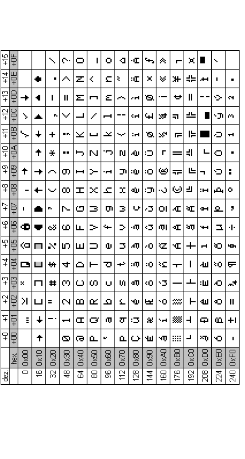
A 01.04
D-80 Handterminal STG
(5)J31069-D0126-U001-A5.1-7418
A.3 ASCII-Tabelle
A
nhang
A
nhang
An
Siemens AG
A&D SE EWF MS
Postfach 2355
D-90713 Fürth
Absender:
Ihr Name: . . . . . . . . . . . . . . . . . . . . . . . . . . . . . . . . . . . . . . . . . . . . . . . . . . .
IhreFunktion: . . . . . . . . . . . . . . . . . . . . . . . . . . . . . . . . . . . . . . . . . . . . . . . . .
IhreFirma: . . . . . . . . . . . . . . . . . . . . . . . . . . . . . . . . . . . . . . . . . . . . . . . . . . .
Straße: . . . . . . . . . . . . . . . . . . . . . . . . . . . . . . . . . . . . . . . . . . . . . . . . . . .
Ort: . . . . . . . . . . . . . . . . . . . . . . . . . . . . . . . . . . . . . . . . . . . . . . . . . . . . . .
Telefon: . . . . . . . . . . . . . . . . . . . . . . . . . . . . . . . . . . . . . . . . . . . . . . . . . .
Bitte kreuzen Sie Ihren zutreffenden Industriezweig an:
-Automobilindustrie
-Chemische Industrie
-Elektroindustrie
-Nahrungsmittel
-Leittechnik
-Maschinenbau
-Petrochemie
-Pharmazeutische Industrie
-Kunststoffverarbeitung
-Papierindustrie
-Textilindustrie
-Transportwesen
-Andere
_____________

Falls Sie auf konkrete Probleme gestoßen sind, erläutern Sie diese bitte in den
folgenden Zeilen:
________________________________
________________________________
________________________________
________________________________
________________________________
________________________________
________________________________
________________________________
________________________________
________________________________
________________________________
________________________________
Anmerkungen/Vorschläge
Ihre Anmerkungen und Vorschläge helfen uns, die Qualität und Benutzbarkeit
unserer Dokumentation zu verbessern. Bitte füllen Sie diesen Fragebogen bei der
nächsten Gelegenheit aus und senden Sie ihn an Siemens zurück.
Titel Ihres Handbuchs: . . . . . . . . . . . . . . . . . . . . . . . . . . . . . . . . . . . . . . . . . .
Bestell-Nummer Ihres Handbuchs: . . . . . . . . . . . . . . . . . . . . . . . . . . . . . . . .
Geben Sie bitte bei den folgenden Fragen Ihre persönliche Bewertung mit Werten
von 1 = gut bis 5 = schlecht an.
1. Entspricht der Inhalt Ihren Anforderungen?
2. Sind die benötigten Informationen leicht zu finden?
3. Sind die Texte leicht verständlich?
4. Entspricht der Grad der technischen Einzelheiten Ihren Anforderungen?
5. Wie bewerten Sie die Qualität der Abbildungen und Tabellen?