Siemens MPCI1V1 Siemens Industrial Access Point/ EAP Family User Manual BAK SCALANCE W786 76
Siemens AG Siemens Industrial Access Point/ EAP Family BAK SCALANCE W786 76
Siemens >
users manual
SIMATIC NET
Betriebsanleitung (kompakt)
Operating Instructions (Compact) Ausgabe/Release 03/2007
SCALANCE W786-1PRO
SCALANCE W786-2PRO
SCALANCE W786-3PRO
Deutsch/English
A5E01048819-01
A5E01048819-01
© SIEMENS AG 2007
Ä
nderungen vorbehalten
Subject to change
ii Betriebsanleitung (kompakt) SCALANCE W786
A5E01048819-01
Inhaltsverzeichnis / Table of Contents
Seite / Page
Deutsch.......................................................................................................................1
English ......................................................................................................................59
Betriebsanleitung (kompakt) SCALANCE W786 iii
A5E01048819-01-04-04
Bitte beachten Sie die Warnhinweise und zusätzlichen Informationen in der Be-
triebsanleitung (kompakt) in Ihrer Sprache im Internet:
http://www4.ad.siemens.de/view/cs/at/18690255
http://www4.ad.siemens.de/view/cs/ch/18690255
http://www4.ad.siemens.de/view/cs/de/18690255
http://www4.ad.siemens.de/view/cs/li/18690255
http://www4.ad.siemens.de/view/cs/lu/18690255
Please observe the warnings and additional information in the user manual (com-
pact) in your language in the Internet:
http://www4.ad.siemens.de/view/cs/au/18690255
http://www4.ad.siemens.de/view/cs/ca/18690255
http://www4.ad.siemens.de/view/cs/gb/18690255
http://www4.ad.siemens.de/view/cs/ie/18690255
http://www4.ad.siemens.de/view/cs/us/18690255
http://www4.ad.siemens.de/view/cs/za/18690255
Veuillez observer les avertissements et informations supplémentaires du manuel
d’utilisation (compact) dans votre langue dans l’internet:
http://www4.ad.siemens.de/view/cs/be/18690255
http://www4.ad.siemens.de/view/cs/ch/18690255
http://www4.ad.siemens.de/view/cs/fr/18690255
http://www4.ad.siemens.de/view/cs/lu/18690255
Osservare le avvertenze di sicurezza e le informazioni aggiuntive nel manuale
d'istruzioni (compatto) nella propria lingua in Internet:
http://www4.ad.siemens.de/view/cs/it/18690255
Por favor, observe las indicaciones de advertencia y las informaciones adicionales
en las instrucciones de servicio (compactas) en su idioma disponibles en Internet:
http://www4.ad.siemens.de/view/cs/cl/18690255
http://www4.ad.siemens.de/view/cs/es/18690255
Berte prosím v úvahu výstražné pokyny a dodatečné informace v provozním návodu
(kompakt) na internetu ve vaší řeči:
http://www4.ad.siemens.de/view/cs/cz/18690255
De bedes iagttage advarselsanvisningerne og de yderligere informationer i
betjeningsvejledningen (kompakt) for Deres sprog på internettet:
http://www4.ad.siemens.de/view/cs/dk/18690255
iv Betriebsanleitung (kompakt) SCALANCE W786
A5E01048819-01
Huomioi internetissä oman kielisessäsi käyttöohjeessa (kompakti) olevat
varoitusohjeet ja lisäinformaatiot:
http://www4.ad.siemens.de/view/cs/fi/18690255
Προσέξτε παρακαλώ τις προειδοποιητικές υποδείξεις και τις πρόσθετες πληροφορίες
στις οδηγίες λειτουργίας (συνεπτηγµένες) στη γλώσσα σας στο διαδίκτυο.
http://www4.ad.siemens.de/view/cs/gr/18690255
请遵守互联网上用您的语言编写的用户手册(简易版)中的警告信息和附加说明:
http://www4.ad.siemens.de/view/cs/cn/18690255
http://www4.ad.siemens.de/view/cs/hk/18690255
http://www4.ad.siemens.de/view/cs/sg/18690255
Kérjük, vegye figyelembe az Interneten található magyar nyelvű használati
utasításban (kompakt) olvasható figyelmeztető utasításokat és a kiegészítő
információkat!
http://www4.ad.siemens.de/view/cs/hu/18690255
Vinsamlegast athugið varúðarábendingar og viðbótarupplýsingar í notendahandbók-
inni (stytt útgáfa) á Netinu:
http://www4.ad.siemens.de/view/cs/is/18690255
以下のインターネットアドレスでお客様の言語による取扱説明書(コンパクト版)
をご覧 http://www4.ad.siemens.de/view/cs/jp/18690255
いただけます。同取扱説明書内に記載された警告事項および補足情報にご注意くだ
さい。
인터넷 http://www4.ad.siemens.de/view/cs/kr/18690255에서 귀하의 사용 언어로
된 사용자 설명서(컴팩트)의 경고 및 추가 정보를 확인하십시오.
لﻴﻟﺩﺒ ﺔﻘﺤﻠﻤﻟﺍ ﺔﻴﻓﺎﻀﻹﺍ ﺕﺎﻤﻭﻠﻌﻤﻟﺍﻭ ﺭﻴﺫﺤﺘﻟﺍ ﺕﺍﺩﺎﺸﺭﺇ ﺓﺎﻋﺍﺭﻤ ﺀﺎﺠﺭﺒ
لﻴﻐﺸﺘﻟﺍ)ﺞﻤﺩﻤﻟﺍ (ﻟﺎﺒﻭﺕﻨﺭﺘﻨﻹﺍ ﺔﻜﺒﺸ ﻕﻴﺭﻁ ﻥﻋ ﻙﻟﺫﻭ ﺎﻬﺒ ﺙﺩﺤﺘﺘ ﻲﺘﻟﺍ ﺔﻐﻠ:
http://www4.ad.siemens.de/view/cs/kw/18690255
Betriebsanleitung (kompakt) SCALANCE W786 v
A5E01048819-01-04-04
Neem de waarschuwingen en de bijkomende informatie in acht, te vinden in de
handleiding (compact) in uw taal in het internet:
http://www4.ad.siemens.de/view/cs/be/18690255
http://www4.ad.siemens.de/view/cs/nl/18690255
Vennligst se advarsler og ytterligere opplysninger i driftsveiledningen (kompakt) på
ditt språk i Internett:
http://www4.ad.siemens.de/view/cs/no/18690255
Por favor observe as advertências e as informações adicionais no manual de
instruções (compacto) na sua língua na internet:
http://www4.ad.siemens.de/view/cs/po/18690255
Var vänlig observera varningarna och tilläggsinformationerna i bruksanvisningen
(kompakt) på ditt språk på Internet:
http://www4.ad.siemens.de/view/cs/se/18690255
Lütfen internette sizin dilinizde sunulan işletme kılavuzundaki (yoğunlaştırılmış) uyarı
bilgilerine ve ek bilgilere dikkat ediniz:
http://www4.ad.siemens.de/view/cs/tr/18690255
vi Betriebsanleitung (kompakt) SCALANCE W786
A5E01048819-01
Safety Guidelines
This manual contains notices you have to observe in order to ensure your personal safety, as well as to prevent
damage to property. The notices referring to your personal safety are highlighted in the manual by a safety alert
symbol, notices referring only to property damage have no safety alert symbol. These notices shown below are
graded according to the degree of danger.
Danger
indicates that death or severe personal injury will result if proper precautions are not taken.
Warning
indicates that death or severe personal injury may result if proper precautions are not taken.
Caution
with a safety alert symbol, indicates that minor personal injury can result if proper precautions are not taken.
Caution
without a safety alert symbol, indicates that property damage can result if proper precautions are not taken.
Notice
indicates that an unintended result or situation can occur if the corresponding information is not taken into
account.
If more than one degree of danger is present, the warning notice representing the highest degree of danger will
be used. A notice warning of injury to persons with a safety alert symbol may also include a warning relating to
property damage.
Qualified Personnel
The device/system may only be set up and used in conjunction with this documentation. Commissioning and
operation of a device/system may only be performed by qualified personnel. Within the context of the safety notes
in this documentation qualified persons are defined as persons who are authorized to commission, ground and
label devices, systems and circuits in accordance with established safety practices and standards.
Prescribed Usage
Note the following:
Warning
This device may only be used for the applications described in the catalog or the technical description and only
in connection with devices or components from other manufacturers which have been approved or
recommended by Siemens. Correct, reliable operation of the product requires proper transport, storage,
positioning and assembly as well as careful operation and maintenance.
Trademarks
All names identified by ® are registered trademarks of the Siemens AG. The remaining trademarks in this
publication may be trademarks whose use by third parties for their own purposes could violate the rights of the
owner.
Disclaimer of Liability
We have reviewed the contents of this publication to ensure consistency with the hardware and software
described. Since variance cannot be precluded entirely, we cannot guarantee full consistency. However, the
information in this publication is reviewed regularly and any necessary corrections are included in subsequent
editions.
Siemens AG
Automation and Drives
Postfach 48 48
90437 NÜRNBERG
GERMANY
Ⓟ 03/2007
Copyright © Siemens AG .
Technical data subject to change
Operating Instructions (compact) SCALANCE W-786
Operating Instructions, , 5
Table of contents
1 Introduction ............................................................................................................................................... 7
1.1 Information on the Operating Instructions (compact) SCALANCE W786 ..................................... 7
2 Description................................................................................................................................................ 9
2.1 Scope of delivery ........................................................................................................................... 9
2.2 Product properties ....................................................................................................................... 10
2.3 LED display.................................................................................................................................. 13
2.4 C-PLUG ....................................................................................................................................... 16
2.5 Reset button................................................................................................................................. 17
2.6 Biological compatibility................................................................................................................. 18
3 Assembling ............................................................................................................................................. 19
3.1 Removing / fitting the housing cover ........................................................................................... 19
3.2 Connecting up cables .................................................................................................................. 21
3.3 Mounting without an adapter (wall mounting only)...................................................................... 24
3.4 Mounting with mounting plate...................................................................................................... 26
3.4.1 Fitting the mounting plate to a wall.............................................................................................. 26
3.4.2 Fitting the mounting plate to an S7 standard rail......................................................................... 28
3.4.3 Fitting the mounting plate to a DIN rail ........................................................................................ 29
3.4.4 Fitting the mounting plate to a mast ............................................................................................ 30
3.4.5 Fitting the SCALANCE W786 to a mounting plate ...................................................................... 31
4 Connecting.............................................................................................................................................. 33
4.1 Lightning protection, power supply, and grounding..................................................................... 33
4.2 Suitable cables for the SCALANCE W786 .................................................................................. 35
4.3 Connecting the cables ................................................................................................................. 36
4.4 Connectors for the power supply of the SCALANCE W786........................................................ 40
4.5 Connecting a power supply adapter............................................................................................ 42
4.6 Connection for Industrial Ethernet............................................................................................... 45
4.7 Connectors for external antennas ............................................................................................... 46
4.8 Inserting / removing the C-PLUG ................................................................................................ 47
5 Technical data......................................................................................................................................... 49
5.1 SCALANCE W786 technical specifications................................................................................. 49
5.2 Permitted antennas...................................................................................................................... 51
6 Certification............................................................................................................................................. 53
6.1 Approvals for SCALANCE W786................................................................................................. 53

Table of contents
Operating Instructions (compact) SCALANCE W-786
6 Operating Instructions, ,
6.2 SCALANCE W786 national approvals......................................................................................... 57
Index....................................................................................................................................................... 61
Operating Instructions (compact) SCALANCE W-786
Operating Instructions, , 7
Introduction 1
1.1 Information on the Operating Instructions (compact)
SCALANCE W786
Validity of the Operating Instructions (compact)
These Operating Instructions (compact) cover the following products:
● SCALANCE W786-1PRO
● SCALANCE W786-2PRO
● SCALANCE W786-3PRO
These Operating Instructions (compact) apply to the following software version:
● SCALANCE W786 firmware as of Version 3.2
Purpose of the Operating Instructions (compact)
Based on the Operating Instructions (compact), you will be able to install and connect up the
SCALANCE W786 correctly. Configuring the SCALANCE W786 and integrating the
SCALANCE W786 in a WLAN are not dealt with in this manual.
Documentation on the accompanying CD
You will find detailed information on configuration in the Operating Instructions SCALANCE
W786 on the accompanying CD in the file
BA_SCALANCE-W786_76.pdf

Introduction
1.1 Information on the Operating Instructions (compact) SCALANCE W786
Operating Instructions (compact) SCALANCE W-786
8 Operating Instructions, ,
Operating Instructions (compact) SCALANCE W-786
Operating Instructions, , 9
Description 2
2.1 Scope of delivery
The following components are supplied with the SCALANCE W786:
● SCALANCE W786
● 5 caps for the cover screws
● Depending on the version, up to 8 plugs for sealing the housing.
● Depending on the version, up to 8 strain relief clamps
● 1 connector for the 48 V DC power supply
● 2 sealing sleeves for FO cables (not for devices with RJ-45 port)
● 1 SIMATIC NET Industrial Wireless LAN CD with these Operating Instructions for the
SCALANCE W78x
● 1 Operating Instructions (compact) SCALANCE W786
Please check that the consignment you have received is complete. If it is not complete,
please contact your supplier or your local Siemens office.

Description
2.2 Product properties
Operating Instructions (compact) SCALANCE W-786
10 Operating Instructions, ,
2.2 Product properties
Possible applications of the SCALANCE W786
The SCALANCE W786 is equipped with an Ethernet port and up to three wireless LAN ports.
This makes the device suitable for the following applications:
● The SCALANCE W786 forwards data within its transmission range from one node to
another without a connection to wired Ethernet being necessary.
● The SCALANCE W786 can be used as a gateway from a wired to a wireless network.
● The SCALANCE W786 can be used as a wireless bridge between two networks.
● The SCALANCE W786 can be used as a bridge between two cells operating at different
frequencies.
With a SCALANCE W786 with more than one WLAN port, you can also implement a
redundant wireless connection to a SCALANCE W78x with at least two WLAN ports.
Properties of the SCALANCE W786
● The Ethernet interface supports 10 Mbps and 100 Mbps, both in full and half duplex as
well as autocrossing and autopolarity.
● Operating the wireless interface in the frequency bands 2.4 GHz and 5 GHz.
● The wireless interface is compatible with the standards IEEE 802.11a, IEEE 802.11h,
IEEE 802.11b and IEEE 802.11g. In the 802.11a, 802.11h and 802.11g mode, the gross
transmission rate is up to 54 Mbps. In turbo mode, the transmission rate is up to 108
Mbps (not permitted in all countries and modes).
● As an expansion of the 802.11a mode, it is also possible to operated according to the
IEEE 802.11h standard. In 802.11h mode, the procedures Transmit Power Control (TPC)
and Dynamic Frequency Selection (DFS) are used in the range 5.25 - 5.35 and 5.47 -
5.75 GHz. In some countries, this allows the frequency subband of 5.47 - 5.725 GHz to
be used outdoors even with a higher transmit power.
TPC is a technique of controlling the transmit power by reducing it to the strength actually
required. With dynamic frequency selection (DFS), the access point searches for primary
users (for example radar) on a randomly selected channel before starting communication.
If signals are found on the channel, this channel is disabled for 30 minutes and the
availability check is repeated on another channel.
● Support of the authentication standards WPA, WPA-PSK, WPA2, WPA2-PSK and
IEEE 802.1x and the encryption methods WEP, AES and TKIP.
● Suitable for inclusion of a RADIUS server for authentication.
● Device-related and application-related monitoring of the wireless connection.
● The interoperability of SCALANCE W786 devices with Wi-Fi devices of other vendors
was tested thoroughly.
Note
In client mode, you can use a SCALANCE W786-xPRO with the functionality of a
SCALANCE W746-1PRO.

Description
2.2 Product properties
Operating Instructions (compact) SCALANCE W-786
Operating Instructions, , 11
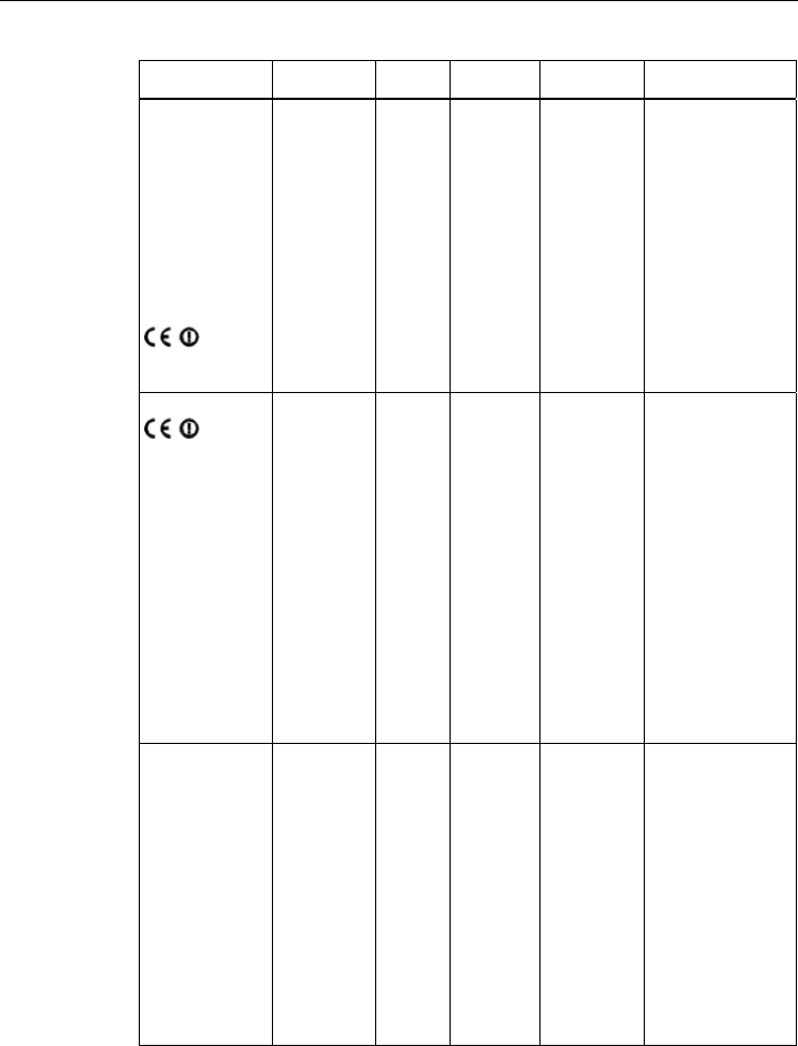
The following table illustrates the differences between the various variants of the
SCALANCE W786:
Type Number of
WLAN ports
Number and
type of
Ethernet ports
Number of
internal
antennas
Number of R-
SMA sockets
for external
antennas
Order no.
W786-1PRO 1 1 RJ-45 1
(diversity(2))
— 6GK5786-
1BA60-2AA0
6GK5786-
1BA60-2AB0
(1)
W786-1PRO 1 1 RJ-45 — 2 6GK5786-
1AA60-2AA0
6GK5786-
1AA60-2AB0
(1)
W786-1 PRO 1 1 ST duplex
multimode FO
cable
1
(diversity(2))
— 6GK5786-
1BB60-2AA0
6GK5786-
1BB60-2AB0
(1)
W786-1 PRO 1 1 ST duplex
multimode FO
cable
— 2 6GK5786-
1AB60-2AA0
6GK5786-
1AB60-2AB0
(1)
W786-2PRO 2 1 RJ-45 2
(diversity(2))
— 6GK5786-
2BA60-2AA0
6GK5786-
2BA60-2AB0
(1)
W786-2PRO 2 1 RJ-45 — 4 6GK5786-
2AA60-2AA0
6GK5786-
2AA60-2AB0
(1)
W786-2 PRO 2 1 ST duplex
multimode FO
cable
2
(diversity(2))
— 6GK5786-
2BB60-2AA0
6GK5786-
2BB60-2AB0
(1)
W786-2 PRO 2 1 ST duplex
multimode FO
cable
— 4 6GK5786-
2AB60-2AA0
6GK5786-
2AB60-2AB0
(1)

Description
2.2 Product properties
Operating Instructions (compact) SCALANCE W-786
12 Operating Instructions, ,
Type Number of
WLAN ports
Number and
type of
Ethernet ports
Number of
internal
antennas
Number of R-
SMA sockets
for external
antennas
Order no.
W786-3PRO 3 1 RJ-45 — 6 6GK5786-
3AA60-2AA0
6GK5786-
3AA60-2AB0
(1)
W786-3 PRO 3 1 ST duplex
multimode FO
cable
— 6 6GK5786-
3AB60-2AA0
6GK5786-
3AB60-2AB0
(1)
(1) US variant
(2) There are two internal antennas per WLAN port. The antenna used is always the one that
provides the best possible data transmission (diversity).
You will find more information on the configuration parameters of the particular device in the
SCALANCE W786 online help of Web Based Management.
Requirements for installation and operation
A PG/PC with a network attachment must be available to configure the SCALANCE W786. If
no DHCP server is available, a PC on which the Primary Setup Tool (PST) is installed is
necessary for the initial assignment of an IP address to the SCALANCE W786. For the other
configuration settings, a computer with Telnet or an Internet browser is necessary.
Description
2.3 LED display
Operating Instructions (compact) SCALANCE W-786
Operating Instructions, , 13
2.3 LED display
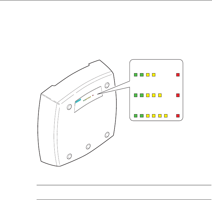
Information on operating status and data transfer
On the front of the housing, several LEDs provide information on the operating status of the
SCALANCE W786:
s
/ 3 5 5 5 )
3R(
6&$/$1&(:
/ 3 5 )
3R(
6&$/$1&(:[
/ 3 5 5 )
3R(
6&$/$1&(:[
/ 3 5 5 5 )
3R(
6&$/$1&(:[
Figure 2-1 The LED display of the SCALANCE W786
Note
The "PoE" LED does not exist on devices with a port for FO cable.

Description
2.3 LED display
Operating Instructions (compact) SCALANCE W-786
14 Operating Instructions, ,
LED Color Description
L1 Green Power supply over a power supply adapter or the 48 V DC energy
contacts of devices with a port for FO cable.
PoE Green Power over Ethernet or power over the 48 V DC energy contacts of
devices with an RJ-45 port.
Yellow Data transfer over the Ethernet interface (traffic).
Green There is a connection over the Ethernet port. (Link).
Flashing yellow PRESET-PLUG detected.
Yellow/green PRESET function completed successfully.
P1
Flashing green "Flashing" enabled over PST.
Yellow Data transfer over the first WLAN interface.
Green
Access Point Mode:
The WLAN interface is initialized and ready for operation.
Client Mode:
There is a connection over the first WLAN port.
Flashing green
Access Point Mode:
The channels are being scanned.
Client Mode:
The client is searching for a connection to an access point or ad hoc
network.
Green flashing
quickly
Access Point Mode:
With 802.11h, the channel is scanned for one minute for primary users
before the channel can be used for data traffic.
Client Mode:
The client waits for the adopt MAC address due to the setting <Auto Find
Adopt MAC> and is connected to no access point.
Green
3x fast,
1x long flashing
Client Mode:
The client waits for the adopt MAC address due to the setting <Auto Find
Adopt MAC> and is connected to an access point.
Flashing yellow PRESET-PLUG detected.
R1
Yellow/green PRESET function completed successfully.
Yellow
Access Point Mode:
Data transfer over the second WLAN port.
Client Mode:
The LED is always off because the 2nd port is not available in client
mode.
Green
Access Point Mode:
The WLAN interface is initialized and ready for operation.
Client Mode:
The LED is always off because the 2nd port is not available in client
mode.
R2
Flashing green
Access Point Mode:
The channels are being scanned.
Client Mode:
The LED is always off because the 2nd port is not available in client
mode.

Description
2.3 LED display
Operating Instructions (compact) SCALANCE W-786
Operating Instructions, , 15
LED Color Description
Green flashing
quickly
Access Point Mode:
With 802.11h, the channel is scanned for one minute for primary users
before the channel can be used for data traffic.
Client Mode:
The LED is always off because the 2nd port is not available in client
mode.
Flashing yellow PRESET-PLUG detected.
Yellow/green PRESET function completed successfully.
Yellow
Access Point Mode:
Data transfer over the third WLAN port.
Client Mode:
The LED is always off because the 3rd port is not available in client
mode.
Green
Access Point Mode:
The WLAN interface is initialized and ready for operation.
Client Mode:
The LED is always off because the 3rd port is not available in client
mode.
Flashing green
Access Point Mode:
The channels are being scanned.
Client Mode:
The LED is always off because the 3rd port is not available in client
mode.
Green flashing
quickly
Access Point Mode:
With 802.11h, the channel is scanned for one minute for primary users
before the channel can be used for data traffic.
Client Mode:
The LED is always off because the 3rd port is not available in client
mode.
Flashing yellow PRESET-PLUG detected.
R3
Yellow/green PRESET function completed successfully.
Red An error occurred during operation with the SCALANCE W786. F
Flashing red Ready to load firmware. The device was either stopped with the reset
button or there is incorrect firmware on the device.
Note
If the LED for the WLAN port is not green when the device starts up, although it is activated,
the port is not ready for operation (interface not initialized).
The main reason for this is usually that during commissioning of the SCALANCE W78x
products, a waiting time of up to 15 minutes can occur when the ambient temperature is
below zero. The device is ready for operation at the specified ambient temperature as soon
as the LED for the WLAN interface is lit green.

Description
2.4 C-PLUG
Operating Instructions (compact) SCALANCE W-786
16 Operating Instructions, ,
2.4 C-PLUG
Configuration information on the C-PLUG
The C-PLUG is used to transfer the configuration of the old device to the new device when a
device is replaced. When the new device starts up with the C-PLUG, it then continues
automatically with exactly the same configuration as the old device. One exception to this
can be the IP configuration if it is set over DHCP and the DHCP server has not been
reconfigured accordingly.
Reconfiguration is necessary if you use WDS or redundancy and use the MAC addresses
and not the sysNames. These functions are then based on the MAC address that inevitably
changes if a device is replaced.
Note
As soon as the device is started with a C-PLUG inserted, the SCALANCE W-700 starts up
with the configuration data on the C-PLUG.
Description
2.5 Reset button
Operating Instructions (compact) SCALANCE W-786
Operating Instructions, , 17
2.5 Reset button
Functions of the reset button
The reset button is located below the housing cover beside the sockets for external
antennas.
Figure 2-2 Position of the reset button with the housing cover removed
The reset button has the following functions:
● Restart of the device
To restart the device, press the reset button.
● Loading new firmware
If the normal procedure with the Load & Save menu of Web Based Management was
completed successfully, the reset button can be used to load new firmware. This situation
can occur if there was a power outage during the normal firmware update.
● Restoring the default parameters (factory defaults)
● Adopting the configuration data from the PRESET PLUG.

Description
2.6 Biological compatibility
Operating Instructions (compact) SCALANCE W-786
18 Operating Instructions, ,
2.6 Biological compatibility
Electromagnetic fields and health
With regard to the question of whether electromagnetic fields (for example in association
with industrial wireless LANs) can put human health at risk, we refer to a publication of
BITKOM (German Association for information Technology, Telecommunication and New
Media e. V.), dated December 2003:
"The same health guidelines apply to WLAN devices as to all other radio applications. These
regulations are based on the protection concept of ICNIRP1 or the corresponding
recommendation of the European Council.
The independent German radiation protection commission (SSK) was commissioned by the
federal German ministry of the environment to investigate the possible dangers - thermal and
non-thermal - resulting from electromagnetic fields and came to the following conclusions2:
'The German Commission on Radiological Protection concludes that according to the latest
scientific literature no new scientific research is available with respect to proven health
hazards which would throw doubt upon the scientific evaluation which serves as the basis for
the ICNIRP safety concepts and the recommendations of the EU commission.'
The SSK also concludes that below the current limit values, these is also no scientific
suspicion of health risks.
This assessment agrees with those of other national and international scientific commissions
and of the WHO (www.who.int/emf).
Accordingly and in view of the fact that WLAN devices are significantly below the
scientifically established limit values, there are no health risks from the electromagnetic fields
of WLAN products.
1 International Council on Non-Ionizing Radiation Protection
2 'Limit Values and Precautionary Measures to Protect the General Public from
Electromagnetic Fields' Recommendation of the Radiation Protection Commission (SSK)
with scientific justification, Issue 29, 2001."
You will find further information on this topic under the following URL:
www.bitkom.org
Operating Instructions (compact) SCALANCE W-786
Operating Instructions, , 19
Assembling 3
3.1 Removing / fitting the housing cover
When does the housing cover need to be removed?
You can only perform the following activities when the cover is removed.
● You want to screw the SCALANCE W786 to a wall or onto the optional mounting plate.
● You want to connect cables to the SCALANCE W786 for the power supply, for Ethernet
or for external antennas.
● You want to insert a C-PLUG in the device or replace an existing C-PLUG.
● You want to use the reset button.
Assembling
3.1 Removing / fitting the housing cover
Operating Instructions (compact) SCALANCE W-786
20 Operating Instructions, ,
Removing the housing cover
s
6&$/$1&(:
/35 55 )
3R(
$
&
%
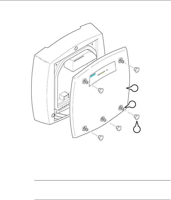
Figure 3-1 Removing the cover
A Sealing cap
B Cover screw
C Housing cover
Follow the steps below to remove the housing cover:
1. Remove the sealing caps from the housing cover (position A in the figure above)
2. Loosen the screws in the cover (position B in the figure above).
Note
These screws remain in the cover after they have been loosened (prevents them being
lost). Never attempt to remove these screws from the housing cover using force,
otherwise the housing cover will be damaged!
3. Remove the housing cover with the captive screws (position C in the figure above).
Fitting the housing cover
Fitting the housing cover is carried out in the reverse order. Tightening torque for the cover
screws 1.8 Nm.
Assembling
3.2 Connecting up cables
Operating Instructions (compact) SCALANCE W-786
Operating Instructions, , 21
3.2 Connecting up cables
Connecting up cables prior to mounting
Before you screw a SCALANCE W786 to a wall or to the optional mounting plate, the cables
for the power supply, for Ethernet, and, when necessary, for the external antennas must be
connected up first. The available options are as follows:
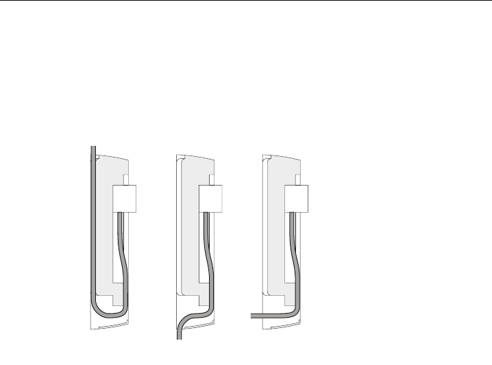
$% &
Figure 3-2 Side view of a SCALANCE W786 with cables entering from different directions
● The cables are inserted from above (position A in the previous schematic). The housing
of the SCALANCE W786 has an opening at the top for this purpose.
● The cables are inserted from below (position B in the previous schematic). There is also
an opening at the bottom for this purpose.
● Cables inserted through a wall behind the SCALANCE W786 (position C in the previous
schematic). In this case, you will need to mount the SCALANCE W786 so that the
opening in the wall is located above the lower edge of the device.
Assembling
3.2 Connecting up cables
Operating Instructions (compact) SCALANCE W-786
22 Operating Instructions, ,
Connecting up FO cables
Fiber-optic cables have a minimum bending radius. The cable must not be bent tighter than
this bending radius during installation or operation, otherwise the FO cable will be irreperably
damaged.
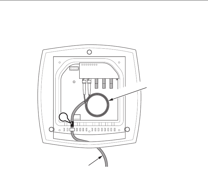
5
5!PP
$
Figure 3-3 Connecting up an FO cable
For the FO cable, use the second opening from the left in the seal. Cable routing is
illustrated in the figure above. For individual cores immediately following the connector, the
minimum bending radius is 25 mm. Refer to the specification of the cable you are using for
the minimum permitted bending radius of the cable within the jacket. Make sure that the FO
cable is not sharply kinked after passing through the housing.
A sealing sleeve must be used in the housing sealing with FO cables (position A in the figure
above). For more detailed information, refer to the section "Connecting the cables".
Assembling
3.2 Connecting up cables
Operating Instructions (compact) SCALANCE W-786
Operating Instructions, , 23
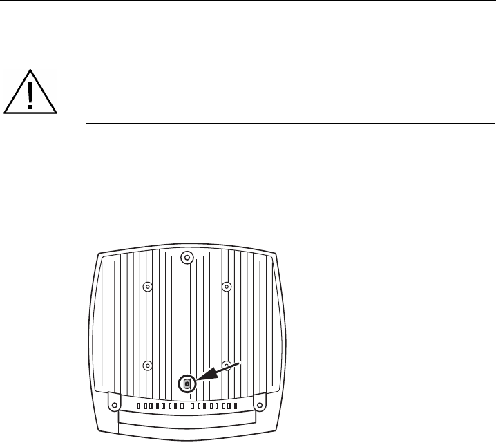
Grounding terminal
Warning
To operate the SCALANCE W786 safely, the chassis ground connector must have a
suitable cable connected. Do not use the SCALANCE W786 without a ground cable
connected.
The chassis ground connector is located on the rear of the device (M4 thread). Connect the
ground cable before you mount the SCALANCE W786 on a wall or on the optional mounting
plate. Once the SCALANCE W786 is mounted, the connector is no longer accessible.
Place the supplied toothed washer directly on the rear of the device before screwing on the
ground cable. Only then can you be sure that there is ideal contact with the screwed-on
cable.
Figure 3-4 Chassis ground connector on the rear of the SCALANCE W786
Assembling
3.3 Mounting without an adapter (wall mounting only)
Operating Instructions (compact) SCALANCE W-786
24 Operating Instructions, ,
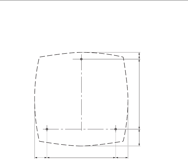
3.3 Mounting without an adapter (wall mounting only)
Drilling template
The location of the holes for mounting the SCALANCE W786 on a wall is shown in the
following figure:
Figure 3-5 Drilling template for wall mounting of the SCALANCE W786
Assembling
3.3 Mounting without an adapter (wall mounting only)
Operating Instructions (compact) SCALANCE W-786
Operating Instructions, , 25
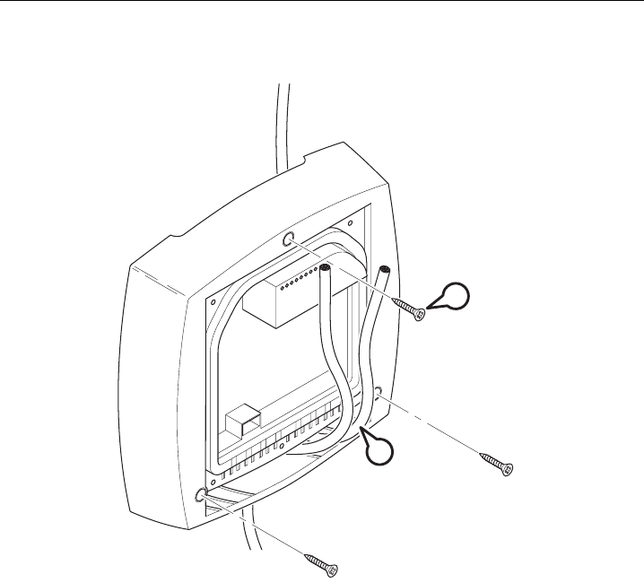
Procedure
$
%
Figure 3-6 SCALANCE W786 wall mounting
Follow the steps below to screw a SCALANCE W786 to a wall:
1. Lead the cables into the housing of the SCALANCE W786 (position A in the figure
above). Note the information in the section "Connecting up cables".
2. Secure the SCALANCE W786 to the wall with three screws (position B in the figure
above). The screws are not supplied with the device. The type and length of the screws
depend on the type of wall.
Option: Threaded holes on rear of housing
When a wall is extremely thin, it is often not possible to use wall plugs for the screws. To
allow wall mounting even in this situation, there are four M4 threaded holes on the rear of the
SCALANCE W786. The drilling template is a square with sides 100 mm long. The device can
therefore be mounted on a wall with bolts through the wall.
Assembling
3.4 Mounting with mounting plate
Operating Instructions (compact) SCALANCE W-786
26 Operating Instructions, ,
3.4 Mounting with mounting plate
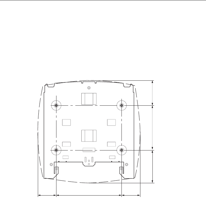
3.4.1 Fitting the mounting plate to a wall
Drilling template
The location of the holes for fitting the mounting plate to a wall is shown in the following
figure:
Figure 3-7 Drilling template for fitting the mounting plate to a wall
Assembling
3.4 Mounting with mounting plate
Operating Instructions (compact) SCALANCE W-786
Operating Instructions, , 27
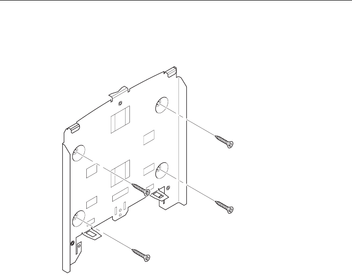
Procedure
Secure the mounting plate to the wall with four screws. The screws are not supplied with the
device. The type and length of the screws depend on the type of wall.
Figure 3-8 Fitting the mounting plate for the SCALANCE W786 to a wall
Assembling
3.4 Mounting with mounting plate
Operating Instructions (compact) SCALANCE W-786
28 Operating Instructions, ,
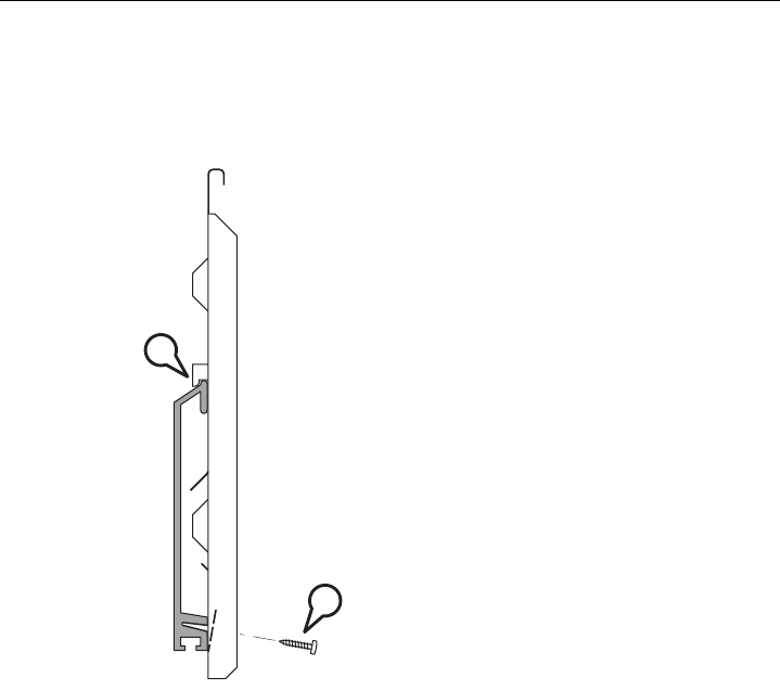
3.4.2 Fitting the mounting plate to an S7 standard rail
Procedure
%
$
Figure 3-9 Side view of a mounting plate on an S7 standard rail
Follow the steps below to fit the mounting plate to an S7 standard rail:
1. Place the mounting plate with the two protruding catches on the top edge of the S7
standard rail (position A in the figure above).
2. At the bottom, the mounting plate has two lugs with holes. Screw the lugs to the S7
standard rail (position B in the figure above). The required screws are supplied with the
mounting plate.
Assembling
3.4 Mounting with mounting plate
Operating Instructions (compact) SCALANCE W-786
Operating Instructions, , 29
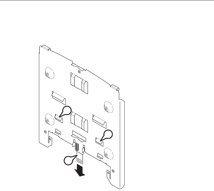
3.4.3 Fitting the mounting plate to a DIN rail
Procedure
$
$
%
Figure 3-10 Mounting plate with fittings for DIN rail mounting
Follow the steps below to fit the mounting plate to a DIN rail:
1. Place the mounting plate with the two catches (position A in the figure above) on the
upper edge of the DIN rail.
2. Pull down the DIN rail sliding catch (position B in the figure above) and press the
mounting plate against the DIN rail until the sliding catch engages.
Assembling
3.4 Mounting with mounting plate
Operating Instructions (compact) SCALANCE W-786
30 Operating Instructions, ,
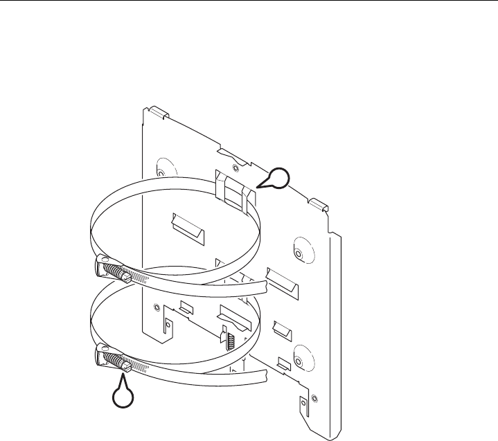
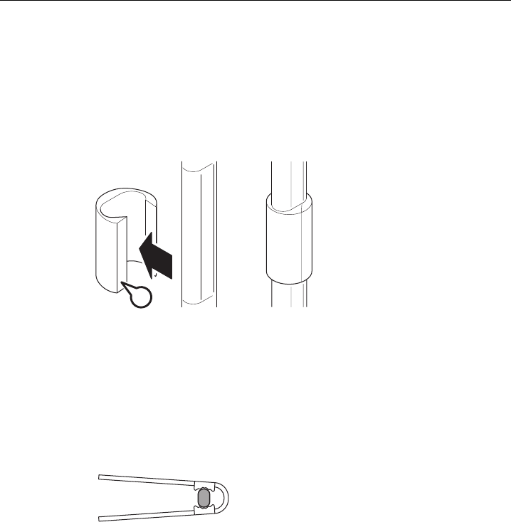
3.4.4 Fitting the mounting plate to a mast
Procedure
%
$
Figure 3-11 Mounting plate with fittings for mast mounting
Follow the steps below to fit the mounting plate to a mast:
1. Feed the fastening straps through the openings in the mounting plate (position A in the
figure above).
2. Place the fastening straps around the mast at the required position.
3. Feed the free end of the strap through the quick-release fastener. You can twist the
tensioning screw (position B in the figure above) to the side to adapt a fastening strap to
the diameter of the mast.
4. Press the tensioning screw against the fastening strap and tighten the tensioning screw,
tightening torque 4.5 Nm.
Assembling
3.4 Mounting with mounting plate
Operating Instructions (compact) SCALANCE W-786
Operating Instructions, , 31
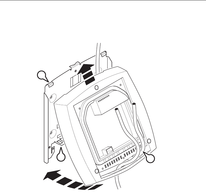
3.4.5 Fitting the SCALANCE W786 to a mounting plate
Procedure
&$
%
Figure 3-12 Fitting the SCALANCE W786 to a mounting plate
Follow the steps below to fit a SCALANCE W786 to a mounting plate:
1. Lead the cables into the housing of the SCALANCE W786 (position A in the figure
above). Note the information in the section "Connecting up cables".
2. Fit the SCALANCE W786 so that the upper edge of the rear of the housing is below the
two catches of the mounting plate (position B in the figure above).
3. Push in the SCALANCE W786 until it engages in the notches at the lower edge of the
mounting plate (position C in the figure above).
Assembling
3.4 Mounting with mounting plate
Operating Instructions (compact) SCALANCE W-786
32 Operating Instructions, ,
&
Figure 3-13 Screwing a SCALANCE W786 to a mounting plate
4. Screw the SCALANCE W786 using the three M4 screws supplied with the mounting plate
(position D in the figure above), tightening torque 1.8 Nm.

Operating Instructions (compact) SCALANCE W-786
Operating Instructions, , 33
Connecting 4
4.1 Lightning protection, power supply, and grounding
Notes on lightning protection
Warning
Antennas installed outdoors must be within the area covered by a lightning protection
system. Make sure that all conducting systems entering from outdoors can be protected by
a lightning protection potential equalization system.
When implementing your lightning protection concept, make sure you adhere to the VDE
0182 or IEC 62305 standard.
A suitable lightning conductor is available in the range of accessories of SIMATIC NET
Industrial WLAN:
Lightning Protector LP798-1PRO (order no. 6GK5798-1LP00-0AA6)
Warning
Installing this lightning protector between an antenna and a SCALANCE W7xx is not
adequate protection against a lightning strike. The LP798-1PRO lightening protector only
works within the framework of a comprehensive lightning protection concept. If you have
questions, ask a qualified specialist company.
Note
The requirements of EN61000-4-5, surge immunity tests on power supply lines, are met only
when a Blitzductor is used with 24 V DC and 48 V DC:
24 V DC: VT AD 24V type no. 918 402
48 V DC: Type no. 919 545 and 919 506 (holder)
Manufacturer: DEHN+SÖHNE GmbH+Co.KG Hans Dehn Str.1 Postfach 1640 D 92306
Neumarkt, Germany

Connecting
4.1 Lightning protection, power supply, and grounding
Operating Instructions (compact) SCALANCE W-786
34 Operating Instructions, ,
Safety extra low voltage
Warning
SCALANCE W78x devices are designed for operation with a directly connectable safety
extra-low voltage or with the power supply adapters available as accessories. Therefore
only safety extra-low voltage (SELV) with limited power source (LPS) complying with
IEC950/EN60950/VDE0805 may be connected to the power supply terminals (exception:
Power supply adapter for 110 - 230 V AC).
The power supply unit to supply the SCALANCE W788 / W74x must comply with NEC
Class 2 (voltage range 18 - 32 V DC, current requirement 1 A)
The power supply unit to supply the SCALANCE W786 must comply with NEC Class 2
(voltage 48 V DC, current requirement 0.3 A)
The device may only be supplied by a power supply unit that meets the requirements of
class 2 power sources of the "National Electrical Code, table 11 (b)". If the power supply is
designed redundantly (two separate power supplies), both must meet these requirements.
Exceptions:
• Power supply with PELV (according to VDE 0100-410) is also possible if the generated
rated voltage does not exceed the voltage limits 25 V AC or 60 V DC.
• Power supply by a SELV power source (according to IEC 60950) or PELV power source
(according to VDE 0100-410) without limited power is also permitted if suitable fire
protection measures are taken by:
– Installation in a cabinet or suitable enclosure
– Installation in an appropriately equipped and closed operating area
Earthing
Caution
There must be no potential difference between the following parts otherwise there is a risk
that the device will be destroyed:
• Ground potential of the power supply and ground potential of the antenna ground.
• Ground potential of the power supply and a grounded housing.
• Ground potential of the power supply and the ground potential of the device connected
to Industrial Ethernet (for example PC, AS-300, AS-400 etc.)
Connect both grounds to the same foundation earth or use an equipotential bonding cable.

Connecting
4.2 Suitable cables for the SCALANCE W786
Operating Instructions (compact) SCALANCE W-786
Operating Instructions, , 35
4.2 Suitable cables for the SCALANCE W786
Cable specification
The following table lists the requirements for a cable depending on the use case.
Application Specification
Direct 48 V DC supply • Round cable cross-section with 6 to 8 mm
diameter.
• Permitted tensile load at least 100 N.
Power supply adapter 12 - 24 V DC • Round cable cross-section with 6 to 8 mm
diameter.
• Permitted tensile load at least 100 N.
Power supply adapter 110 - 230 V AC • Round cable cross-section with 6 to 8 mm
diameter.
• Three-core cable with 0.5 - 2.5 mm2 cross
section of the individual cores.
• Permitted tensile load at least 100 N.
Ethernet IE FC TP Standard Cable GP 2 x 2 (type A)
Order no. 6XV1 840-2AH10
IE TP Torsion Cable 2 x 2 (type C)
Order no. 6XV1 870-2F
IE FC TP Trailing Cable 2 x 2 (type C)
Order no. 6XV1 840 3AH10
Multimode FO cable FO Standard Cable GP
Order no. 6XV1 873-2A
Minimum bending radius 65 mm.
You will find detailed information on
preassembled cable lengths and connectors in
the catalog "IK PI".
Antenna connector IWLAN antenna extension cable FRNC
Length 5 m
Order no. 6XV1 875-3FH50
Length 15 m
Order no. 6XV1 875-3FN15
Connecting
4.3 Connecting the cables
Operating Instructions (compact) SCALANCE W-786
36 Operating Instructions, ,
4.3 Connecting the cables
Procedure
Warning
Danger from line voltage
If the housing is not perfectly sealed, there is a danger to life due to the line voltage if the
SCALANCE W786 is subjected to spray water or dampness. Make sure that you keep to
the following safety rules.
• Before connecting up, turn of the power supply.
• The sealing of the cable feedthroughs of the SCALANCE W786 is only assured when
the cable has a suitable diameter and adequate tensile strength. Only use cables that
meet the specifications in the section "Cables for the SCALANCE W786". When
connecting up a FO cable, make sure that you use the sealing sleeve supplied with the
SCALANCE W786.
• Never wrap insulating tape, adhesive tape or other materials around thinner cables to
achieve the required diameter. In this case, neither the housing seal nor the strain relief
clamps can fulfill their function.
• Close all unused openings in the housing seal with the sealing plugs supplied with the
SCALANCE W786. Do not use fillers or any other material under any circumstances.
Connecting
4.3 Connecting the cables
Operating Instructions (compact) SCALANCE W-786
Operating Instructions, , 37
&
'
$
%
Figure 4-1 Connecting a cable and fitting the strain relief clamps
Follow the steps below to connect cables to the SCALANCE W786.
1. Connect the cables to the appropriate contacts. (Position A in the figure above) You have
the following options:
– Connect cables preassembled with a connector (Ethernet, antennas) by inserting the
connector into the appropriate socket. Secure antenna cables by tightening the sleeve
nut of the connector (key size SW8). You will find more information on this topic in the
sections "Connection for Industrial Ethernet" and "Connections for external antennas".
– 48 V DC power supply. Use the connector supplied with the SCALANCE W786. For
details of the terminal assignment, refer to the section "Connectors for the power
supply".
– 12 - 24 V DC or 110 - 230 V AC power supply. With these power supplies, you require a
power supply adapter (do not ship with the SCALANCE W786). You will find more
information in the section "Connecting a power supply adapter".
2. Fit a strain relief clamp to the connected cable. The toothed part of the clamp must
enclose the cable completely (as shown by position B in the figure above).
3. Press the strain relief clamp into the housing until the cable is located completely in the
opening in the housing seal (position C in the figure above).
Connecting
4.3 Connecting the cables
Operating Instructions (compact) SCALANCE W-786
38 Operating Instructions, ,
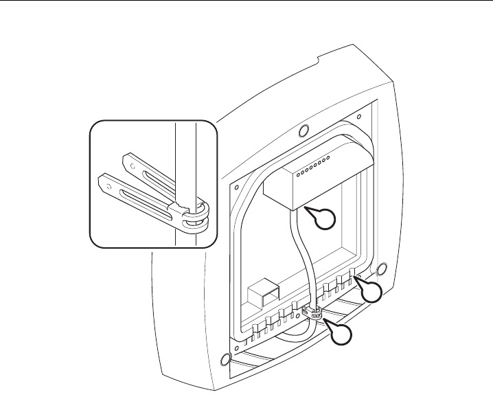
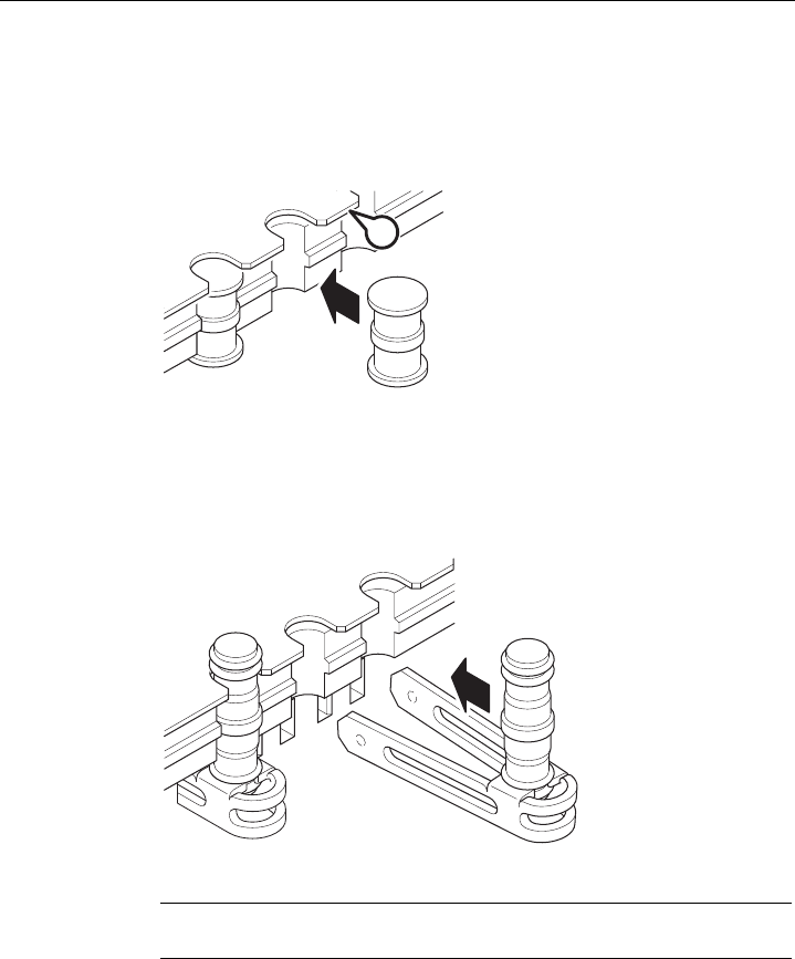
4. Seal all openings not required for cables with sealing plugs (position D in the figure
above). There are two versions of sealing plug:
Short type
The upper end face of a dummy plug must be located below the cover plate (position E in
the figure below).
(
Figure 4-2 Location of the sealing plugs below the cover plate
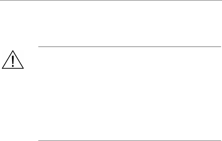
Long design
Fit these sealing plugs in a strain relief clamp. The lower surrounding notch must be
enclosed by the toothing of the strain relief clamp (as shown in the figure below). Press
the strain relief clamp into the housing until the dummy plug is located completely in the
opening of the housing seal.
Figure 4-3 Securing a long sealing plug with a strain relief clamp
Note
Keep unused sealing plugs and strain relief clamps for later use.
Connecting
4.3 Connecting the cables
Operating Instructions (compact) SCALANCE W-786
Operating Instructions, , 39
Points to note when connecting an FO cable
The FO cable specified for use with the SCALANCE W786 does not have a circular cross
section. As a result, remember the following points when connecting up such cables.
Sealing sleeve
Fit the sealing sleeve at the point where the cable goes through the housing seal. Only then
will you achieve perfect sealing of the housing. Follow the steps outlined below:
$
%
Figure 4-4 Fitting a sealing sleeve to an FO cable
1. Open the sealing sleeve as shown in the figure above and place the FO cable in it.
2. Remove the protective foil (position A in the figure above) and join the sealing sleeve
together (position B in the figure above).
Strain relief clamp
When you fit the strain relief clamp, make sure that the FO cable is in the correct position.
The shorter sides of the cable must make contact with the toothing of the strain relief clamp.
Figure 4-5 View from above with an FO cable inserted in the strain relief clamp

Connecting
4.4 Connectors for the power supply of the SCALANCE W786
Operating Instructions (compact) SCALANCE W-786
40 Operating Instructions, ,
4.4 Connectors for the power supply of the SCALANCE W786
Possible power supplies
The following power supplies are suitable for the SCALANCE W786:
● 48 V DC direct voltage
Use the two-pin connector supplied with the SCALANCE W786.
● 12 - 24 V DC direct voltage
Use the power supply adapter 12 - 24 V DC available as an accessory.
● 110 - 230 V DC direct voltage
Use the power supply adapter 110 - 230 V DC available as an accessory.
● Power over Ethernet (PoE)
PoE is possible only when voltage is modulated on the data lines (one of the two options
named in IEEE 802.3af "phantom power") because all Ethernet cables specified for the
SCALANCE W786 have four cores.
Connecting
4.4 Connectors for the power supply of the SCALANCE W786
Operating Instructions (compact) SCALANCE W-786
Operating Instructions, , 41
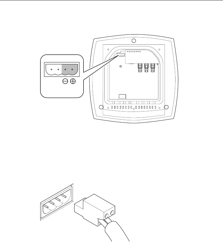
Procedure for connecting the supplied connector for 48 V DC
'&9
Figure 4-6 Position of the opening in the housing for the power supply with the housing cover
removed
Perform the following steps to connect a 48 V DC cable to a SCALANCE W786:
1. Connect the supplied connector to the 48 V DC cable. The figure above shows the
location of the socket in the housing and the contact assignment. The connector is safe
against polarity reversal and can only be inserted in the right-hand half of the housing
When connecting the cores, you should therefore make sure that the connector is
oriented as shown in the following figure.
Figure 4-7 Position of the connector when inserted in the socket of the housing
2. Press the connector into the socket in the housing until it engages.
3. Secure the power cable with a strain relief clamp. For more detailed information on this
topic, refer to the section "Connecting the cables".

Connecting
4.5 Connecting a power supply adapter
Operating Instructions (compact) SCALANCE W-786
42 Operating Instructions, ,
4.5 Connecting a power supply adapter
Input voltage options
The optional power supply adapter is available in two versions:
● Power supply adapter for 24 V DC direct voltage
● Power supply adapter for 110 - 230 V AC alternating voltage
Note
If a SCALANCE W786-3PRO is operated with diversity for three antenna pairs, the power
for 24 V DC cannot be supplied redundantly. In this case, there is no further opening in
the housing for a second power cable.
How to fit the power supply adapter
Warning
Danger from line voltage
Power supply cables may only be connected when the power is turned off!
Start up the SCALANCE W786 only after screwing the housing cover in place again so that
protection from touching live parts is restored!
Connecting
4.5 Connecting a power supply adapter
Operating Instructions (compact) SCALANCE W-786
Operating Instructions, , 43
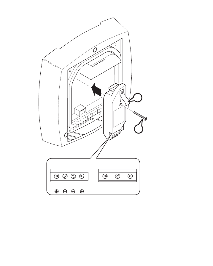
9 9
/00/ /13(
%
$
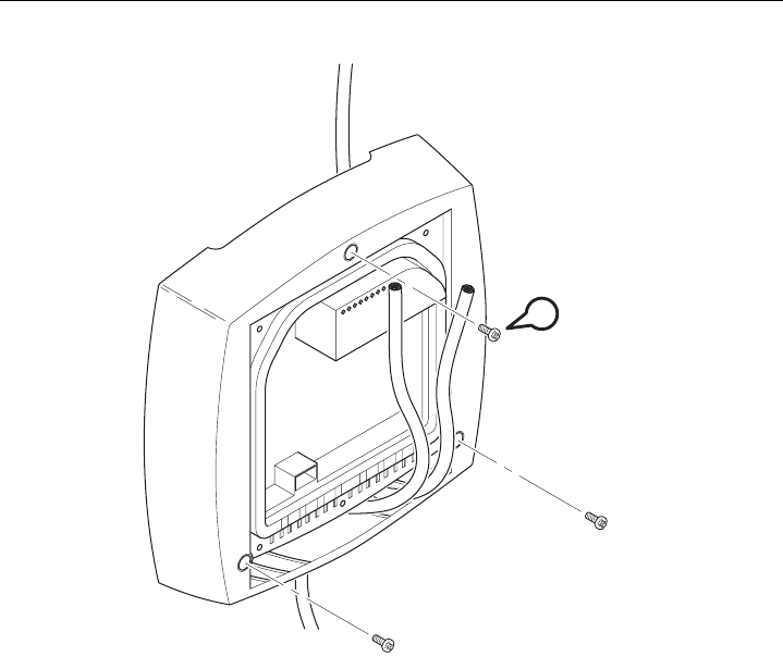
Figure 4-8 Using a power supply adapter in a SCALANCE W786
Follow the steps below to fit and connect a power supply adapter:
1. Fit the power supply adapter in the SCALANCE W786 as shown in the figure above. The
connector on the rear of the power supply adapter must engage fully in the socket of the
housing. The entire rear surface of the power supply adapter must make contact with the
inner surface of the SCALANCE W786.
Caution
Only use the loop (position B in the figure above) to remove the power supply adapter
from the SCALANCE W786! This prevents the connector skewing on the back of the
power supply adapter and breaking off.
2. Connect the power supply adapter and the SCALANCE W786 with the screw supplied
with the power supply adapter (position A in the figure above).

Connecting
4.5 Connecting a power supply adapter
Operating Instructions (compact) SCALANCE W-786
44 Operating Instructions, ,
3. Connect the cable for the power supply. The assignment of the contacts is illustrated in
the figure above.
4. Secure the power supply cable with a strain relief clamp. For more detailed information
on this topic, refer to the section "Connecting the cables".
How to remove the power supply adapter
Follow the steps below to remove a power supply adapter from a SCALANCE W786:
Warning
Danger from line voltage
Disconnect power supply cables only when the power to the power supply adapter is turned
off!
1. Disconnect the power supply cable from the power supply adapter.
2. Loosen the securing screw of the power supply adapter (position A in the figure above).
3. Pull the loop (position B in the figure above) to remove the connector on the rear of the
power supply adapter from the socket in the housing and remove the power supply
adapter.
Connecting
4.6 Connection for Industrial Ethernet
Operating Instructions (compact) SCALANCE W-786
Operating Instructions, , 45
4.6 Connection for Industrial Ethernet
Device variants
With a SCALANCE W786, you have the choice of two Ethernet ports:
● RJ-45 jack
● ST duplex socket for multimode FO cables 1310 nm and a maximum cable length of
3000 m
Procedure for connecting an Ethernet cable
5;
7;
67'XSOH[
Figure 4-9 Position of the Ethernet port with the housing cover removed
Perform the following steps to connect an Ethernet cable to a SCALANCE W786:
1. Insert the connector of the Ethernet cable in the corresponding socket of the SCALANCE
W786. If you use FO cables, make sure that the transmit and receive lines are correctly
connected. The location of the socket for RX and TX is shown in the figure above.
2. Secure the Ethernet cable with a strain relief clamp. For more detailed information on this
topic, refer to the section "Connecting the cables".
Connecting
4.7 Connectors for external antennas
Operating Instructions (compact) SCALANCE W-786
46 Operating Instructions, ,
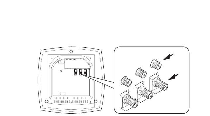
4.7 Connectors for external antennas
How to connect external antennas
$
%
Figure 4-10 Position of the ports for external antennas with the housing cover removed
For each WLAN port, there are two R-SMA sockets on a SCALANCE W786 to connect
external antennas. The figure above shows how the R-SMA sockets are assigned to the
WLAN ports. With a SCALANCE W786-1PRO, only the socket pair labeled "1" exists; with a
SCALANCE W786-2PRO the sockets labeled "1" and "2" exist.
Perform the following steps to connect a cable for an external antenna to a SCALANCE
W786:
1. Insert the connector on the antenna cable into the R-SMA socket and tighten the sleeve
nut on the socket (key size SW8), tightening torque 0.6 Nm. If you want to use a port for
two antennas, connect the line for antenna "B" first. After connecting the cable for
antenna "A", the socket for "B" is not easy to reach.
2. Screw a terminating resistor to the unused socket if you use only one antenna on a port.
3. Secure the antenna cable(s) with a strain relief clamp. For more detailed information on
this topic, refer to the section "Connecting the cables".
Connecting
4.8 Inserting / removing the C-PLUG
Operating Instructions (compact) SCALANCE W-786
Operating Instructions, , 47
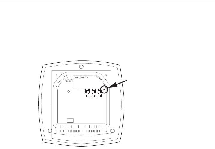
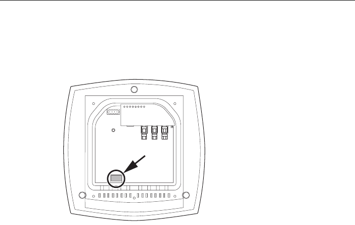
4.8 Inserting / removing the C-PLUG
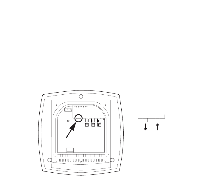
Inserting the C-PLUG
Figure 4-11 Location of the C-PLUG with the housing cover removed
The housing of the C-PLUG has a protruding ridge on the long side. The C-PLUG can only
be inserted when this ridge is at the top right. The slot in the SCALANCE W786 has a
corresponding groove at this position. Make sure that the C-PLUG is inserted completely into
the slot.
Removing the C-PLUG
Insert a screwdriver between the right-hand front edge of the C-PLUG and the slot and
release the C-PLUG.

Connecting
4.8 Inserting / removing the C-PLUG
Operating Instructions (compact) SCALANCE W-786
48 Operating Instructions, ,

Operating Instructions (compact) SCALANCE W-786
Operating Instructions, , 49
Technical data 5
5.1 SCALANCE W786 technical specifications
Data transfer
Ethernet transfer rate 10/100 Mbps
Wireless transmission rate 1 ... 54 Mbps (108 Mbps)
Wireless standards supported 802.1x
802.11a
802.11b
802.11e
802.11g
802.11h
802.11i
Power supply standards supported 802.3af (Power over Ethernet)
interfaces
Power • 48 V DC supply via supplied connector
• RJ-45 jack Power over Ethernet
(48 V DC)
• 2 x 24 V DC supplies with optional power supply
adapter (available as accessory)
• 110 - 230 V AC with optional power supply
adapter (available as accessory)
Data • RJ-45 jack for Ethernet
or on devices for FO cable:
1 x 2 BFOC sockets
• depending on version, up to six R-SMA antenna
sockets

Technical data
5.1 SCALANCE W786 technical specifications
Operating Instructions (compact) SCALANCE W-786
50 Operating Instructions, ,
Electrical data
PoE 12.9 W
48 V DC 12.9 W
24 V DC (adapter) 15 W
Power consumption depending on power supply
110 - 230 V AC
(adapter)
15 W
Construction
Dimensions
(W x H x D)
251 mm x 251 mm x 72 mm
Without power supply
adapter
2241 g
With power supply
adapter 24 V DC
2428 g
Weight
(version with three IWLAN ports)
With power supply
adapter
110 - 230 V AC
2433 g
Permitted ambient conditions
Operating temperature -40°C ... 70°C
Devices with fiber optic cable: -25°C ... 70°C
Transport/storage temperature -40°C ... 85°C
Degree of protection Tested to IP65
MTBF information (mean time between failure)
SCALANCE W786 MTBF 61 years

Technical data
5.2 Permitted antennas
Operating Instructions (compact) SCALANCE W-786
Operating Instructions, , 51
5.2 Permitted antennas
Accessories for SCALANCE W-700
Note
When you select an antenna, keep in mind the national approvals for your SCALANCE
W7xx.
Characteristics Type Frequency /
GHz
Antenna gain /
dBi
Impedance / Ω Order No.
2,4 6 Omni ANT795-6MN
5 8
50 6GK5795-
6MN00-0AA6
Omni ANT792-6MN 2,4 6 50 6GK5792-
6MN00-0AA6
Omni ANT793-6MN 5 6 50 6GK5793-
6MN00-0AA6
2,4 9 Patch ANT795-6DN
5 9
50 6GK5795-
6DN00-0AA6
Directional
antenna
ANT792-8DN 2,4 14 50 6GK5792-
8DN00-0AA6
Directional
antenna
ANT793-8DN 5 18 50 6GK5793-
8DN00-0AA6
Helix
(for RCoax)
ANT792-4DN 2,4 4 50 6GK5792-
4DN00-0AA6
λ5/8
(for RCoax)
ANT793-4MN 5 6 6GK5793-
4MN00-0AA6
RCoax IWLAN RCoax
PE 1/2" 2.4
GHz
2,4 0 50 6XV1875-2A
RCoax IWLAN RCoax
PE 1/2" 5 GHz
5 0 50 6XV1875-2D

Technical data
5.2 Permitted antennas
Operating Instructions (compact) SCALANCE W-786
52 Operating Instructions, ,
Operating Instructions (compact) SCALANCE W-786
Operating Instructions, , 53
Certification 6
6.1 Approvals for SCALANCE W786
CE conformity
The products
SIMATIC NET SCALANCE W786-1PRO
SIMATIC NET SCALANCE W786-2PRO
SIMATIC NET SCALANCE W786-3PRO
in the version put into circulation by Siemens A&D meets the regulations of the following
European directives:
● 99/5/EC
Directive of the European Parliament and of the Council on radio equipment and
telecommunications terminal equipment and the mutual recognition of their conformity.
Conformity with the basic requirement of the directive is attested by adherence to the
following standards:
● EN 60950
Safety of information technology equipment
● EN 301489-1
Electromagnetic compatibility for radio equipment and services
● EN 301489-17
Specific requirements for broadband data transmission systems and for equipment in
local high-performance wireless networks (HIPERLAN)
● EN 300328
Electromagnetic compatibility and radio spectrum issues
● EN 301893
Broadband radio access networks (BRAN) – 5 GHz high-performance RLAN
● EN 50371
Compliance of low power electronic and electrical apparatus with the basic restrictions
related to human exposure to electromagnetic fields (10 MHz to 300 GHz)
● 1999/519/EC
Council recommendation on the limitation of exposure of the general public to
electromagnetic fields (0 Hz to 300 GHz)
Devices connected to the system must meet the relevant safety regulations.
Certification
6.1 Approvals for SCALANCE W786
Operating Instructions (compact) SCALANCE W-786
54 Operating Instructions, ,
The EC Declaration of Conformity is available for the responsible authorities according to the
above-mentioned EC Directive at the following address:
Siemens Aktiengesellschaft
Automation and Drives
Industrielle Kommunikation
Postfach 4848
D-90327 Nürnberg
This declaration certifies compliance with the directives named above, but does not
guarantee any specific properties.
Note
The specified approvals apply only when the corresponding mark is printed on the product.

Certification
6.1 Approvals for SCALANCE W786
Operating Instructions (compact) SCALANCE W-786
Operating Instructions, , 55
FCC approval
This device complies with Part 15 of the FCC Rules
Operation is subject to the following two conditions:
(1) this device may not cause harmful interference, and
(2) this device must accept any interference received, including interference that may cause
undesired operation.
IEEE802.11b or g operation of this product in the USA is firmware-limited to channels 1
through11.
_________________________________________________________________________________
Notice
Changes or modifications made to this equipment not expressly approved by SIEMENS may
void the FCC authorization to operate this equipment.
_________________________________________________________________________________
This equipment has been tested and found to comply with the limits for a Class B digital
device, pursuant to Part 15 of the FCC Rules. These limits are designed to provide
reasonable protection against harmful interference in a residential installation. This
equipment generates, uses and can radiate radio frequency energy and, if not installed and
used in accordance with the instructions, may cause harmful interference to radio
communications. However, there is no guarantee that interference will not occur in a
particular installation. If this equipment does cause harmful interference to radio or television
reception, which can be determined by turning the equipment off and on, the user is
encouraged to try to correct the interference by one or more of the following measures:
● Reorient or relocate the receiving antenna.
● Increase the separation between the equipment and receiver.
● Connect the equipment into an outlet on a circuit different from that to which the receiver
is connected.
Consult the dealer or an experienced radio/TV technician for help.
_________________________________________________________________________________
Notice
This equipment complies with FCC radiation exposure limits set forth for an uncontrolled
environment. This equipment should be installed and operated with minimum distance 20 cm
between the radiator and your body.
_________________________________________________________________________________
This transmitter must not be co-located or operating in conjunction with any other antenna or
transmitter.
Professional Installation Notice:
To comply with FCC part 15 rules in the United States, the system must be professionally
installed to ensure compliance with the Part 15 certification. It is the responsibility of the
operator and professional installer to ensure that only certified systems are deployed in the
United States. The use of the system in any other combination (such as co-located antennas
transmitting the same information) is expressly forbidden.

Certification
6.1 Approvals for SCALANCE W786
Operating Instructions (compact) SCALANCE W-786
56 Operating Instructions, ,
RSS-210 of Industry Canada
"Operation is subject to the following two conditions: (1) this device may not cause
interference, and (2) this device must accept any interference, including interference that
may cause undesired operation of the device."
"This device has been designed to operate with the antennas listed below, and having a
maximum gain of 18 dBi. Antennas not included in this list or having a gain greater than 18
dBi are strictly prohibited for use with this device. The required antenna impedance is 50
ohms."
"To reduce potential radio interference to other users, the antenna type and its gain should
be so chosen that the equivalent isotropically radiated power (e.i.r.p.) is not more than that
permitted for successful communication."
"That the device for the band 5150-5250 MHz is only for indoor usage to reduce potential for
harmful interference to co-channel mobile satellite systems."
"Users should also be cautioned to take note that high power radars are allocated as primary
users (meaning they have priority) of 5250-5350 MHz and 5650-5850 MHz and these radars
could cause interference and/or damage to LE-LAN devices."
Certification
6.2 SCALANCE W786 national approvals
Operating Instructions (compact) SCALANCE W-786
Operating Instructions, , 57
6.2 SCALANCE W786 national approvals
National approvals
Below, you will find the channels approved by the Institute of Electrical and Electronics
Engineers, Inc. (IEEE) that can be used by SCALANCE W-786 devices for 802.11h mode.
The channels approved for the standards 802.11a/b/g are not listed and are enabled for
operation in specific countries based on the configuration.
Countries in which there is no approval according to the IEEE 802.11h standard are not
listed.
Column Description
Country Country
Mode IEEE 802.11 standard and the TPC and / or DFS functionality, where required
CH Channel
MHz Frequency
PWR (EIRP) Maximum permitted effective isotropic radiated power
Use Permitted use indoors and / or outdoors
The SCALANCE W786 products are approved in the following countries:
Country Mode CH MHz PWR
(EIRP)
Use
Belgium
11b 11g
g-Turbo
11a
TPC
11h
DFS+TPC
DFS+TPC
1
-
13
36
-
48
36
-
64
100
-
140
2412
-
2472
5180
-
5240
5180
-
5320
5500
-
5700
100 mW
60 mW
200 mW
1000 mW
Indoor only
Indoor only
Indoor only
Indoor + outdoor
Certification
6.2 SCALANCE W786 national approvals
Operating Instructions (compact) SCALANCE W-786
58 Operating Instructions, ,
Country Mode CH MHz PWR
(EIRP)
Use
Denmark
Germany
Finland
Great Britain
Italy
The Netherlands
Austria
Sweden
Switzerland
Spain
11b 11g
g-Turbo
11a
TPC
11h
DFS+TPC
DFS+TPC
1
-
13
36
-
48
36
-
64
100
-
140
2412
-
2472
5180
-
5240
5180
-
5320
5500
-
5700
100 mW
60 mW
200 mW
1000 mW
Indoor + outdoor
Indoor only
Indoor only
Indoor + outdoor
France
11b 11g
g-Turbo
11a
TPC
11h
DFS+TPC
DFS+TPC
1
-
7
8
-
13
36
-
48
36
-
64
100
-
140
2412
-
2442
2447
-
2472
5180
-
5240
5180
-
5320
5500
-
5700
100 mW
100 mW
60 mW
200 mW
1000 mW
Indoor + outdoor
Indoor only
Indoor only
Indoor only
Indoor + outdoor
Canada 11b 11g
g-Turbo
11a
TPC
TPC
11a-Turbo
TPC
TPC
TPC
1
-
11
36
-
48
149
-
165
42
152
160
2412
-
2462
5180
-
5240
5745
-
5825
5210
5760
5800
1000 mW
200 mW
1000 mW
200 mW
1000 mW
1000 mW
Indoor + outdoor
Indoor only
Indoor + outdoor
Indoor only
Indoor + outdoor
Indoor + outdoor

Certification
6.2 SCALANCE W786 national approvals
Operating Instructions (compact) SCALANCE W-786
Operating Instructions, , 59
Country Mode CH MHz PWR
(EIRP)
Use
United States of
America
11b 11g
g-Turbo
11a
TPC
TPC
11a-Turbo
TCP
TPC
TPC
1
-
11
36
-
48
149
-
165
42
152
160
2412
-
2462
5180
-
5240
5745
-
5825
5210
5760
5800
1000 mW
200 mW
1000 mW
200 mW
1000 mW
1000 mW
Indoor + outdoor
Indoor only
Indoor + outdoor
Indoor only
Indoor + outdoor
Indoor + outdoor
Operating Instructions (compact) SCALANCE W-786
Operating Instructions, , 61
Index
C
C-PLUG, 16
E
Earthing, 34
I
IEEE 802.11, 10
IEEE 802.11a, 10
IEEE 802.11b, 10
IEEE 802.11g, 10
L
Lightning protection, 33
S
Safety extra low voltage, 34