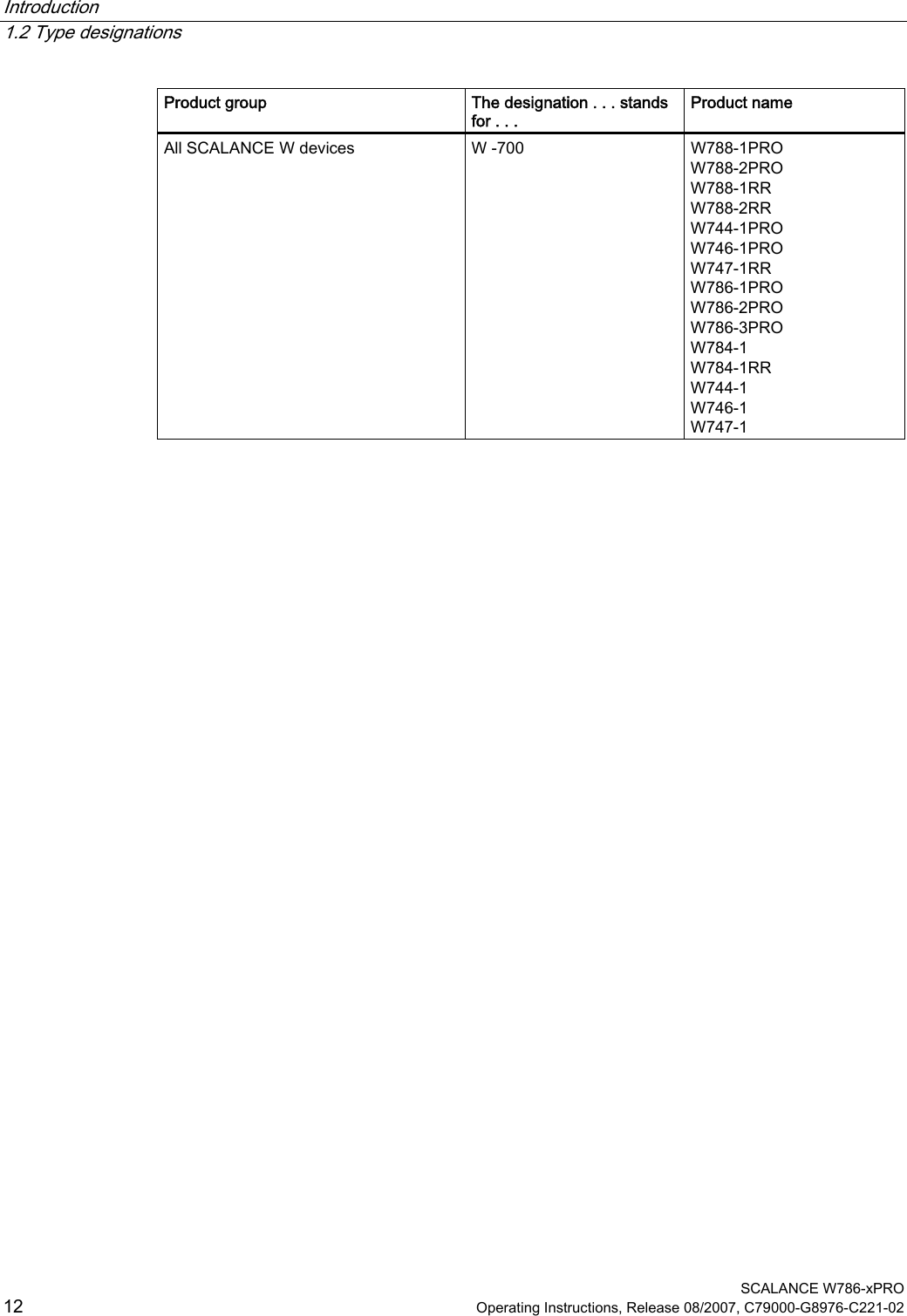
Siemens MPCI1V2 Wireless LAN Access Point Module User Manual SCALANCE W786 xPRO
Siemens AG Wireless LAN Access Point Module SCALANCE W786 xPRO
UserManual.wiki
>
Siemens
>
MPCI1V2 User Manual
>
Manual
Contents
1.
Users Manual
2.
Users Manual Statement
3.
User manual statement FCC Indoor use
4.
Manual
5.
Manual Statement
Manual
Navigation menu
Upload a User Manual
Namespaces
Wiki Guide
HTML
PDF
Info
Views
User Manual
Discussion / Help
Navigation
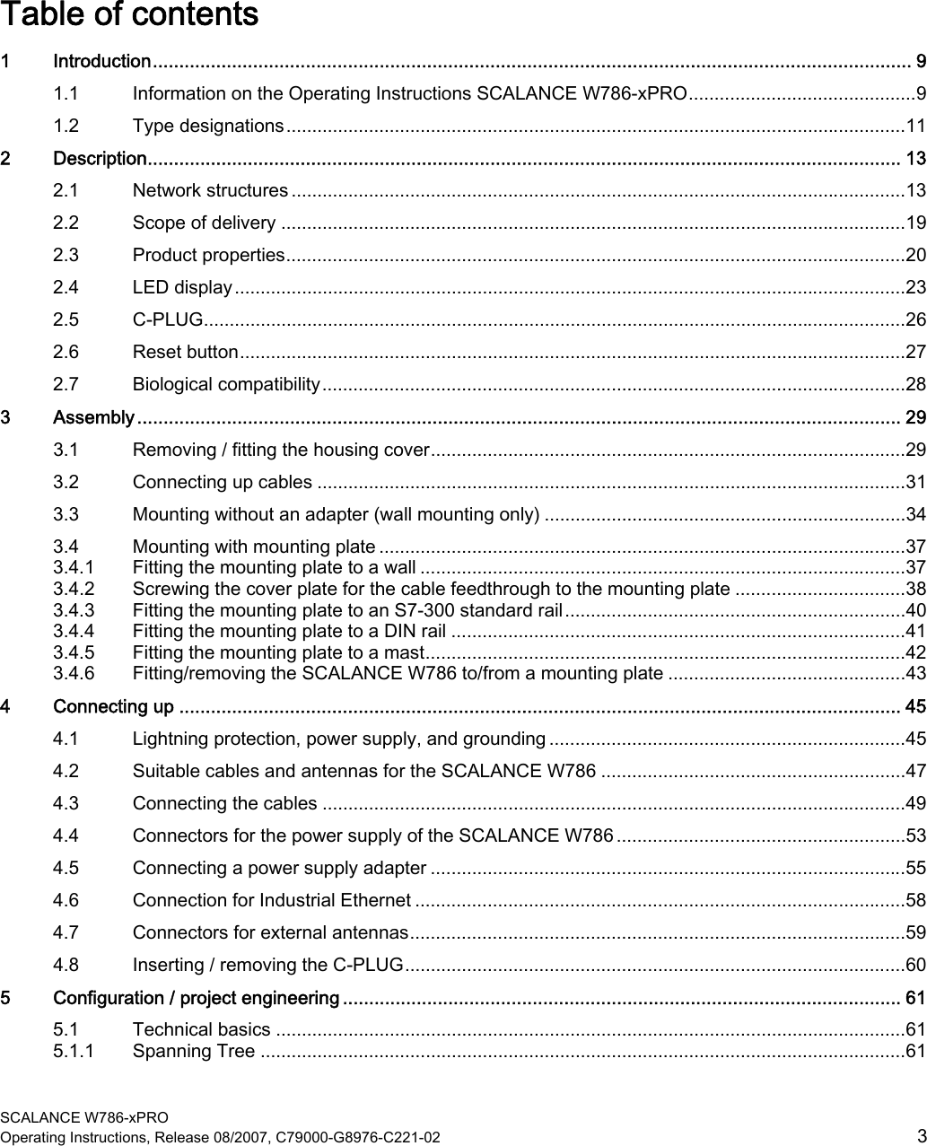


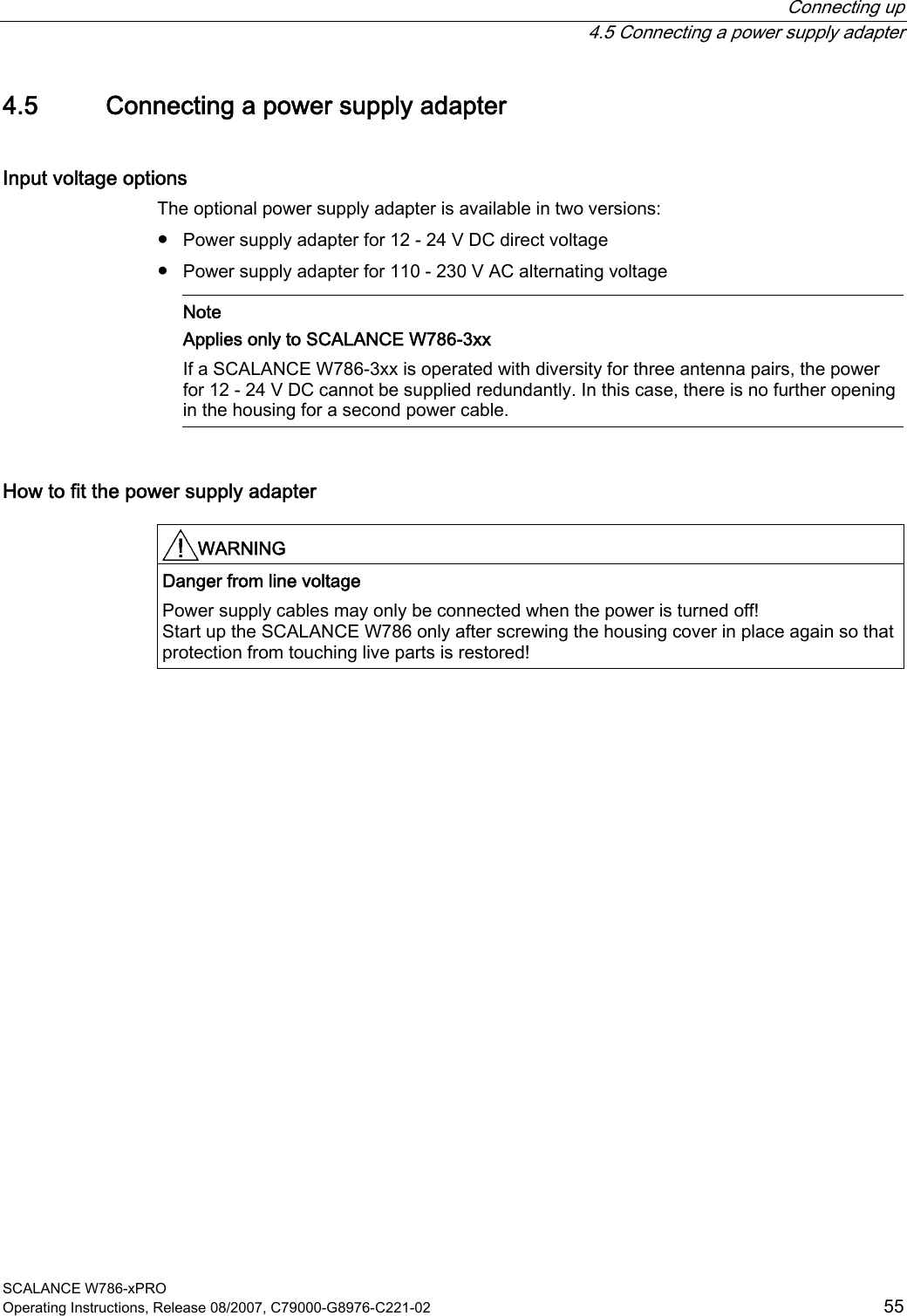
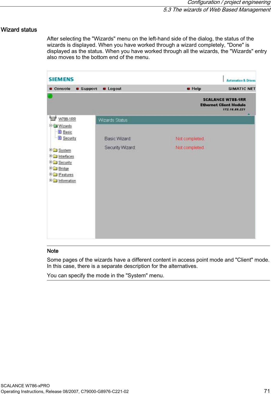
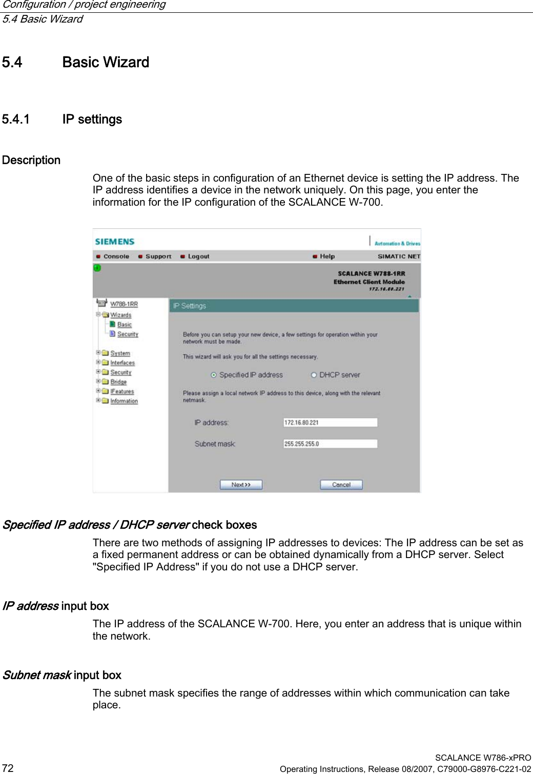
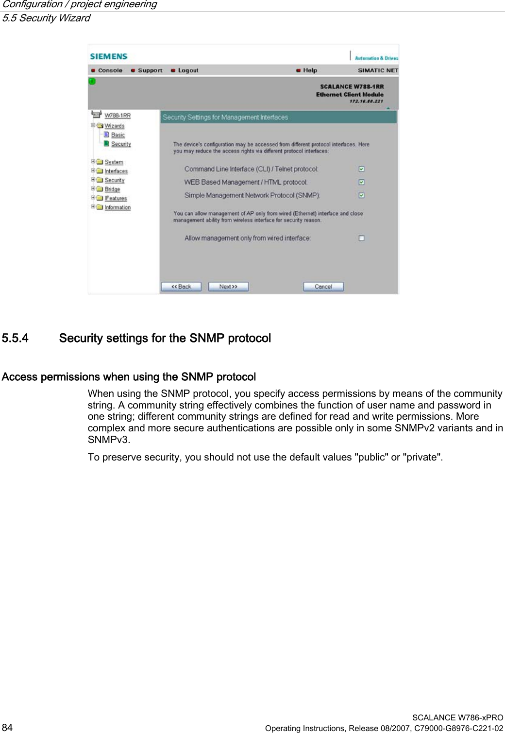
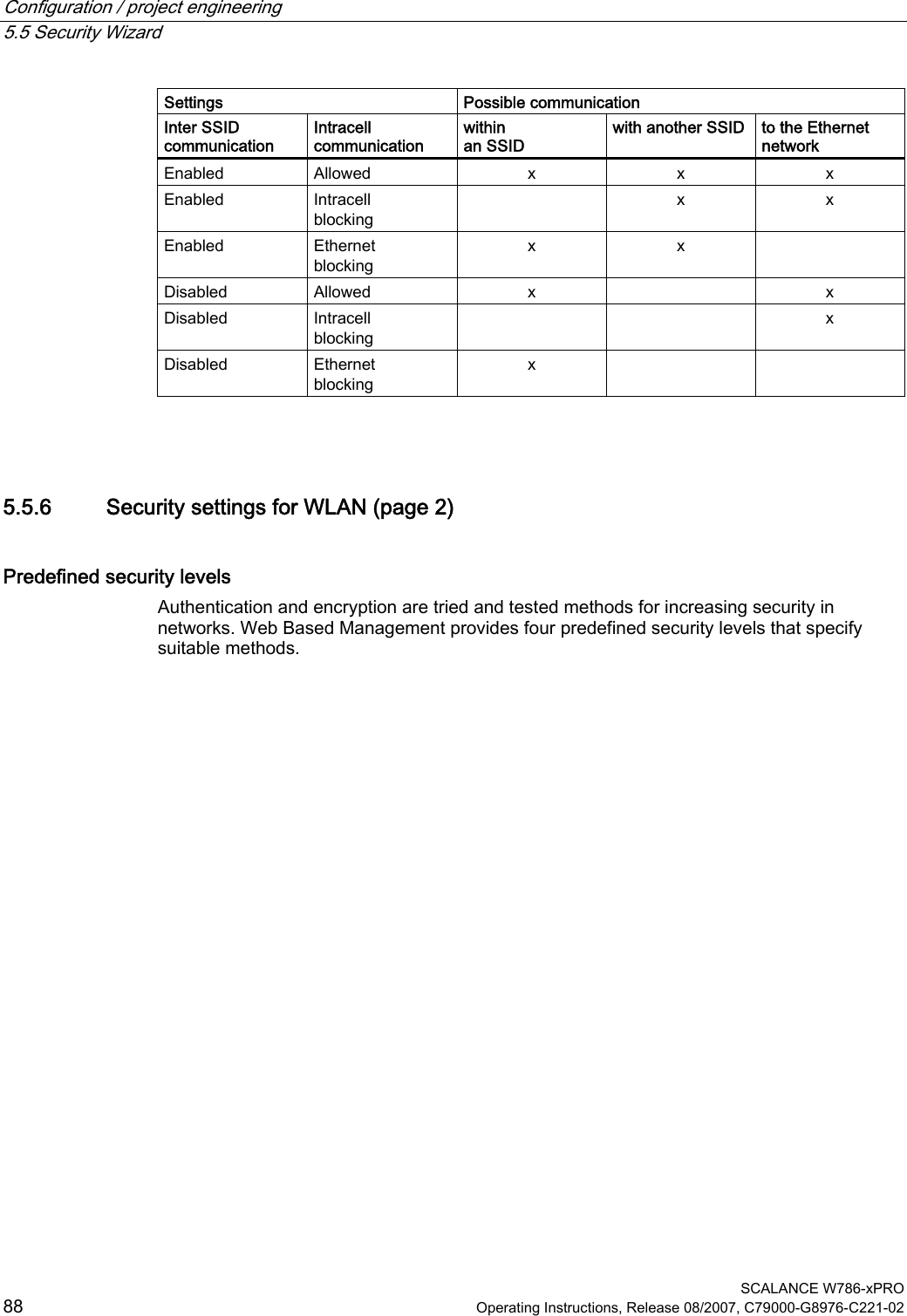
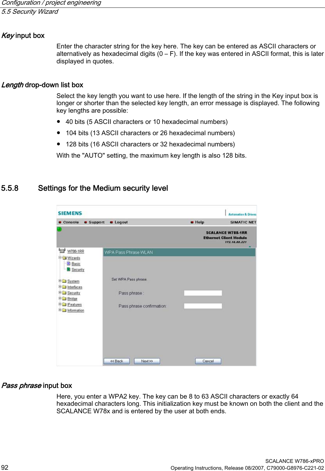
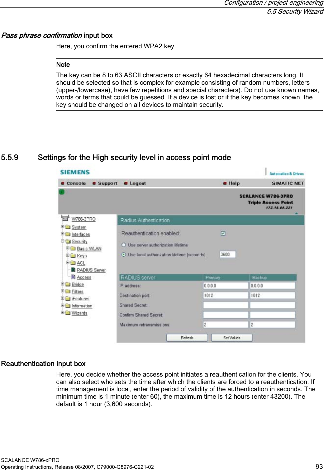
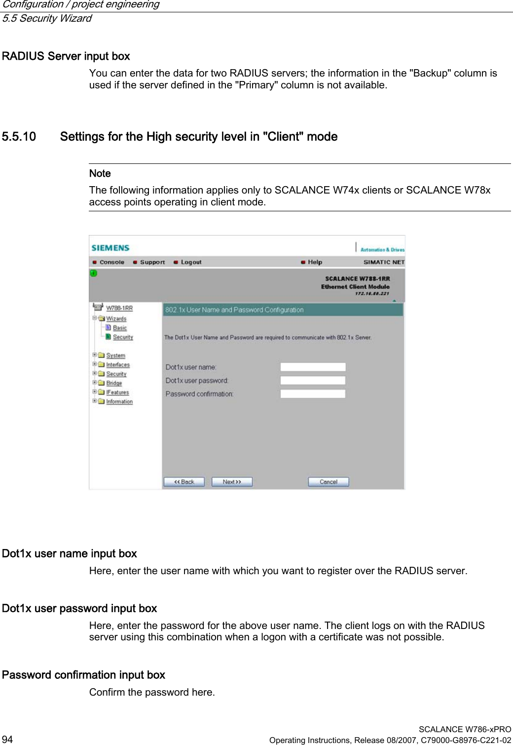
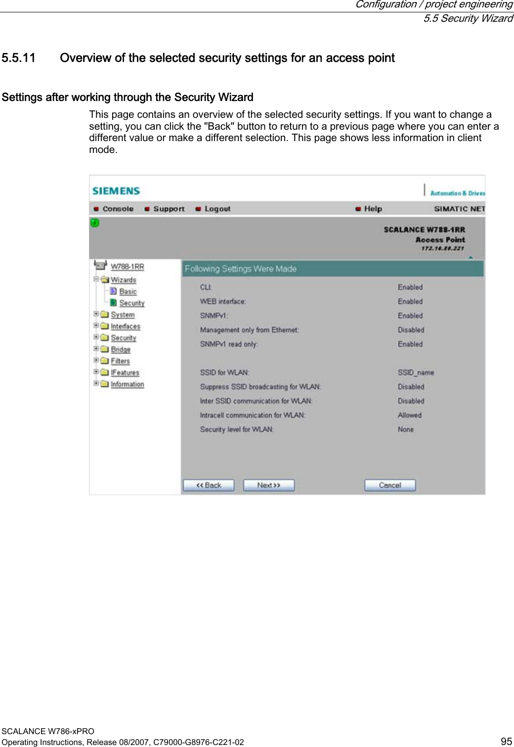
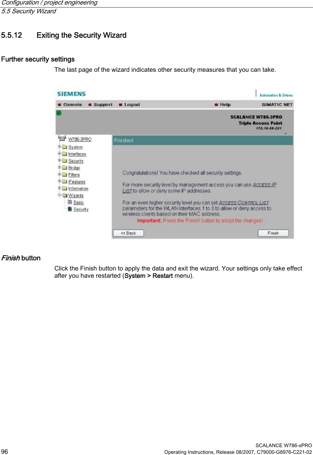
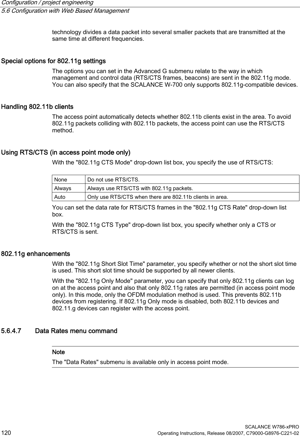
![Configuration / project engineering 5.5 Security Wizard SCALANCE W786-xPRO 82 Operating Instructions, Release 08/2007, C79000-G8976-C221-02 5.5 Security Wizard 5.5.1 Introduction With the Security Wizard, you can specify security-related parameters without detailed knowledge of security technology in wireless networks. Note The SCALANCE W700 can be operated even if you do not set the security parameters. Depending on the properties of your network, there is then, however, an increased risk of unauthorized access. You should therefore work through all the pages of the Security Wizard, so that you have at least basic security functions. 5.5.2 Security settings Password First, set a new admin password. Enter the string twice in the text boxes of this page. The password can be up to a maximum of 31 characters long. When assigning the password, ASCII code 0x20 to 0x7e is used. The following characters are supported: Numbers 0...9 Letters abcdefghijklmnopqrstuvwxyz ABCDEFGHIJKLMNOPQRSTUVWXYZ Special characters !"#$%&'()*+,-./:;<=>?@[\]^_`{|}~ and the blank Until you set a password, the defaults set in the factory apply: The default password for the "admin" user is "admin". You can use the wizards only if you log on as administrator. Note For the US variant of the SCALANCE W-700, the password for the "admin" user has been changed; it can, however, be obtained from Siemens Support by specialists for professional WLAN installation.](https://usermanual.wiki/Siemens/MPCI1V2.Manual/User-Guide-916091-Page-82.png)
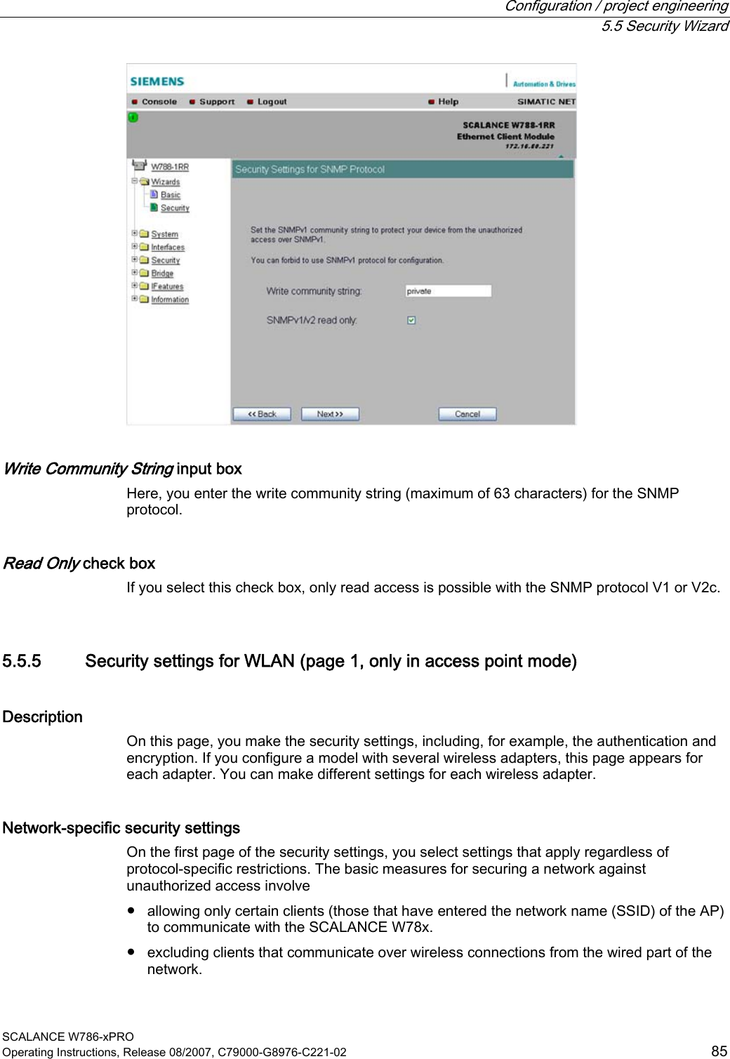
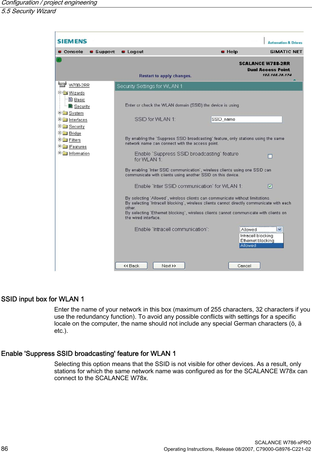
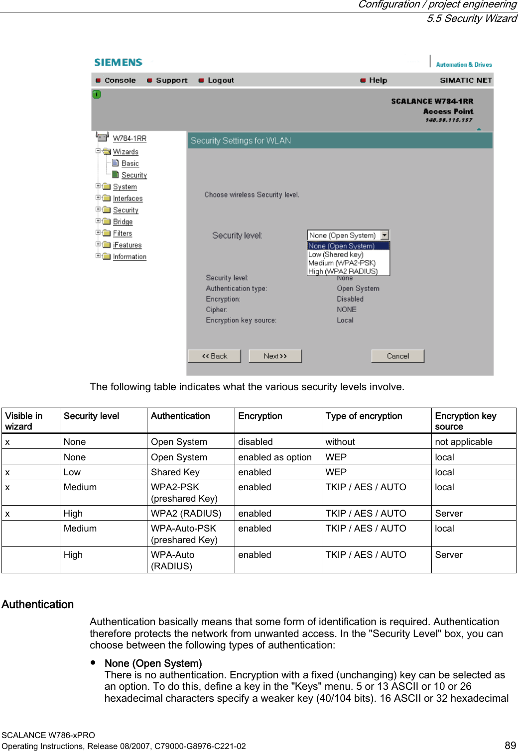
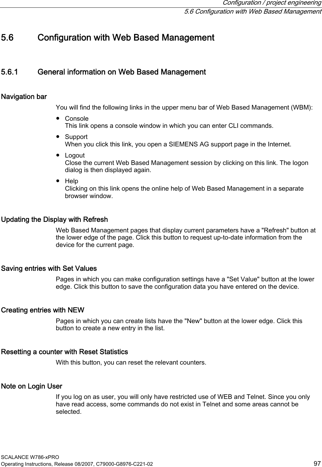
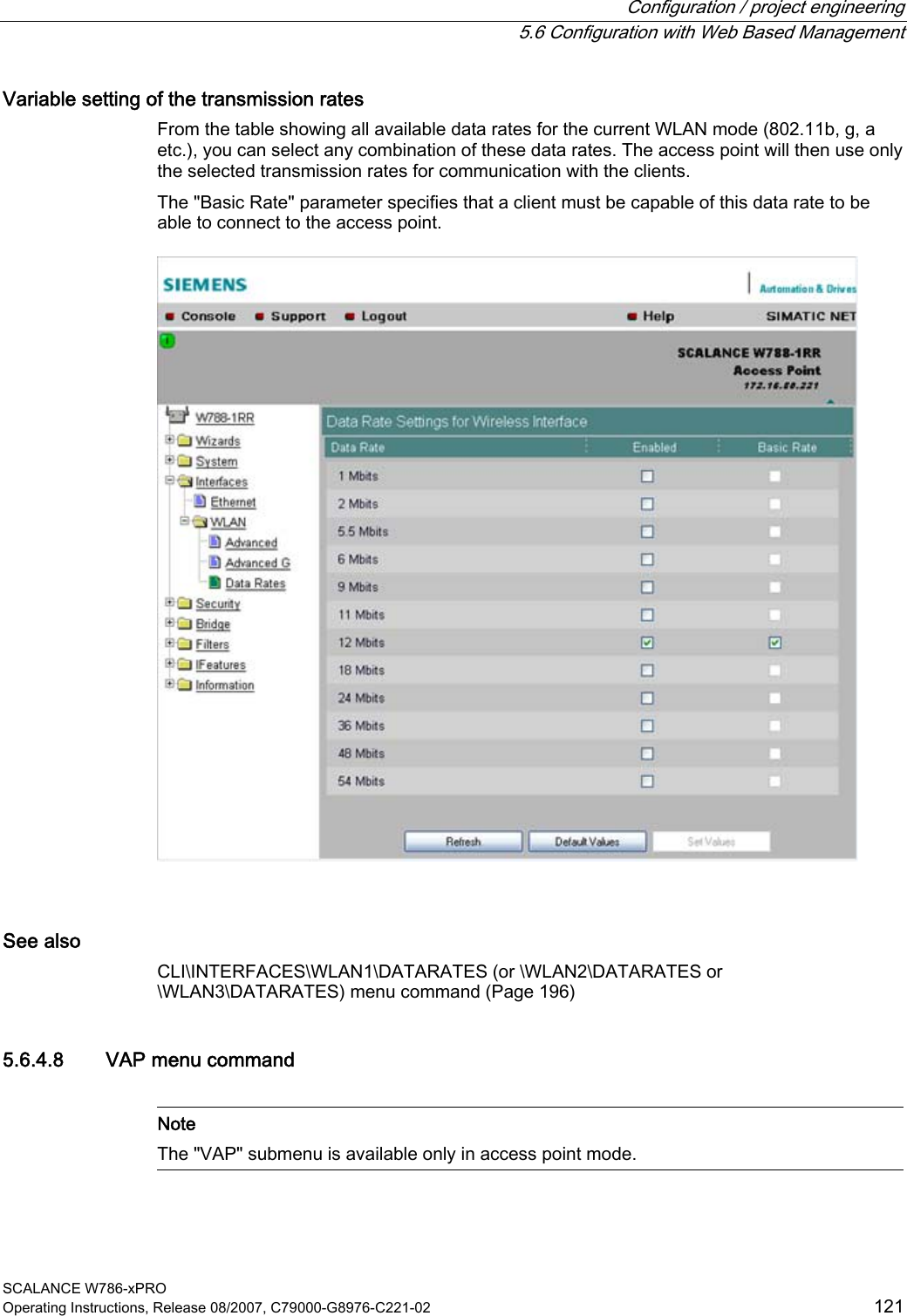
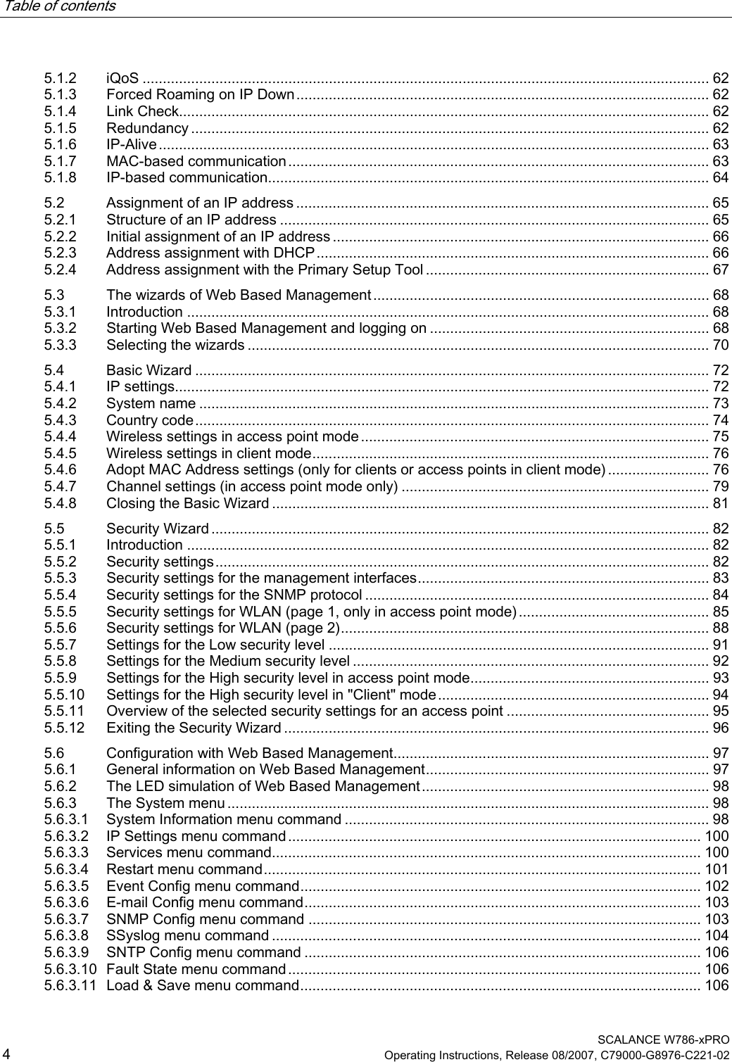
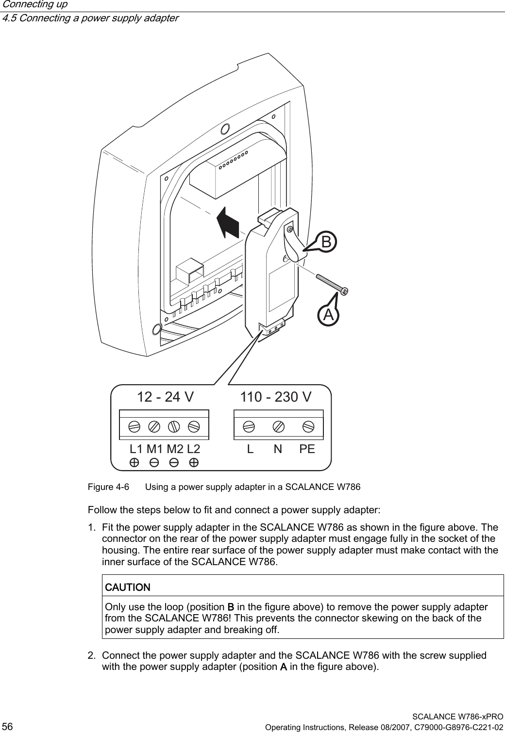
![Configuration / project engineering 5.6 Configuration with Web Based Management SCALANCE W786-xPRO Operating Instructions, Release 08/2007, C79000-G8976-C221-02 127 ● Enter the WPA-PSK password ● Specifies the "Group Key Update Intervals" in WPA-PSK ● Enable "Suppress SSID broadcasting" Where they apply, all other security parameters are adopted from the Security > Basic > WLAN1 or WLAN2 or WLAN3 page. 5.6.5.3 Keys menu command Specifying the WEP key To allow you to enable the encryption for the Open System and Shared Key authentication methods, you must first enter at least one key in the key table. You can choose between several key lengths. 5 or 13 ASCII or 10 or 26 hexadecimal characters specify a weaker key (40/104 bits). 16 ASCII or 32 hexadecimal characters, on the other hand, define a strong key (128 bits). You can also create keys for WDS Redundancy and ACL Private (these are not supported by all clients for ACL). Note For the key, you can use characters 0x20 to 0x7e from the ASCII code. Below, there is a list of all supported characters starting with a space: !"#$%&'()*+,-./0123456789:;<=>?@ ABCDEFGHIJKLMNOPQRSTUVWXYZ[\]^_` abcdefghijklmnopqrstuvwxyz{|}~ See also CLI\SECURITY\KEYS\WLAN1 (or \WLAN2 or \WLAN3) menu command (Page 200) 5.6.5.4 ACL menu command Note The "ACL" menu is available only in access point mode. Access rights for individual clients The access control list (ACL) is and assignment of MAC addresses and access rights. If ACL is enabled, prior to data transfer, the access point checks whether the necessary permissions for the communication partner (identified by the MAC address) are entered in the ACL table](https://usermanual.wiki/Siemens/MPCI1V2.Manual/User-Guide-916091-Page-127.png)

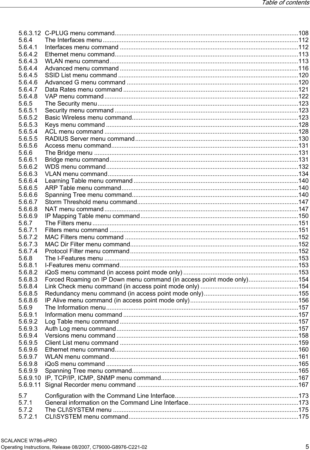
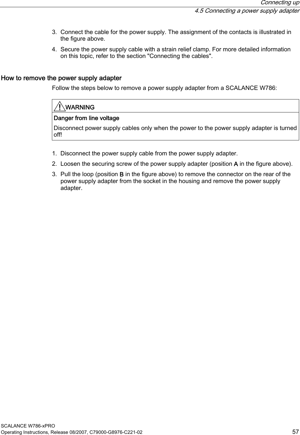
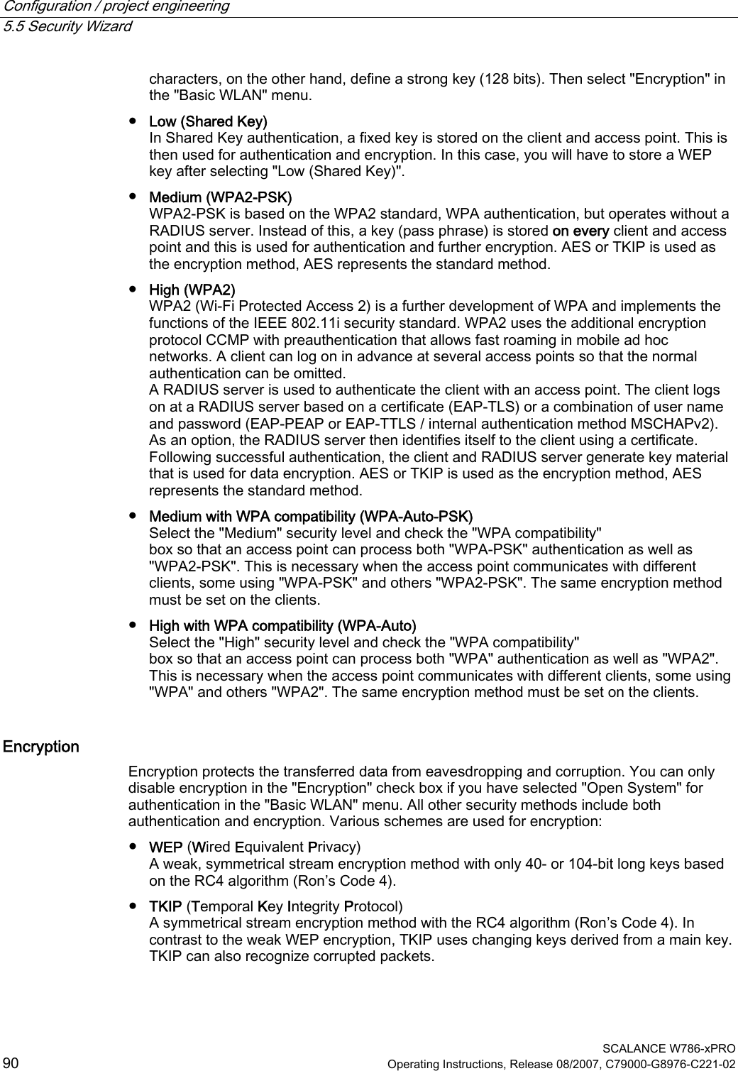
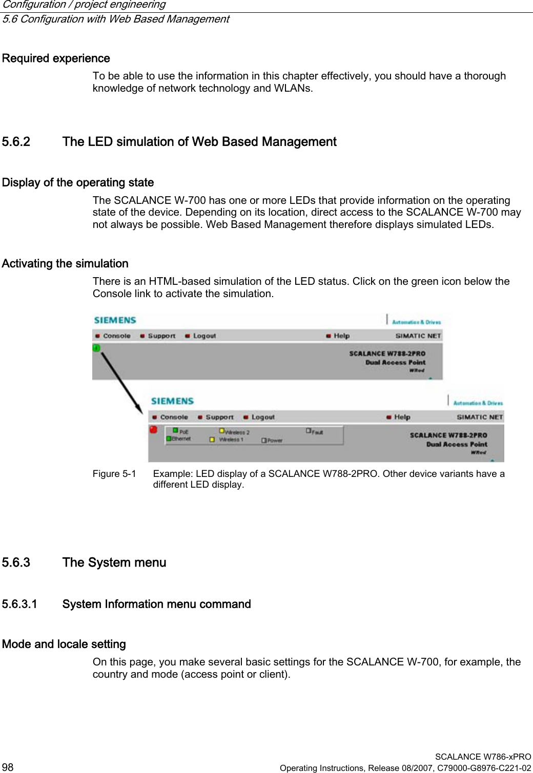
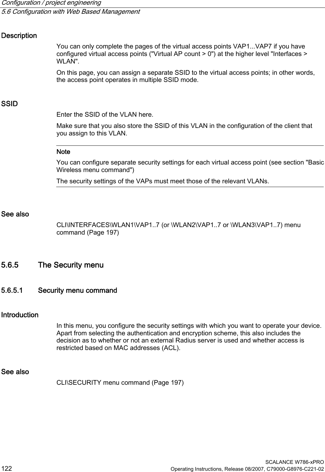
![Configuration / project engineering 5.7 Configuration with the Command Line Interface SCALANCE W786-xPRO Operating Instructions, Release 08/2007, C79000-G8976-C221-02 173 Shortcuts for commands As an alternative, instead of entering full CLI commands, you can simply enter the first letter or the first few letters of the command and then press the Tab key. The Command Line Interface then displays a command starting with the letter or letters you typed in. If the command displayed is not the command you require, press the Tab key again to display the next command. Directory structure Before you can enter a command in the Command Line Interface, you must first open the required menu or submenu. The following tables contain the commands of a menu and a description of them. The menu containing the commands is shown before the table. The table lists only the commands themselves. Symbols for representing CLI commands CLI commands generally have one or more parameters that are represented in the syntax description as follows: ● Mandatory parameters are shown in pointed brackets. Example: <IP address> ● Optional parameters are shown in square brackets. Example: [E|D] If you omit an optional parameter, the commands output the currently set value. ● Alternative input values are separated by the pipe character. In this case, you specify one of the listed values as the parameter. Example: [E|D] you enter either "E" or "D". ● If a numeric value is required as a mandatory parameter, you can also specify a range of values: Example: <0 ... 255> You enter a value between 0 and 255. Cross-menu commands You can use the commands in the following table in any menu. CLI\ ... > Comment Command Description IWLAN/ PB LINK W744 W746 W747 W78x W78xRR / Moves you one menu level higher. ✔ ✔ ✔ ✔ ✔ ✔ ? Displays the commands and submenus available in the menu. ✔ ✔ ✔ ✔ ✔ ✔ Cannot be called using the command shortcuts. exit Closes the CLI/Telnet session. ✔ ✔ ✔ ✔ ✔ ✔ restart Restarts the SCALANCE W7xx Cannot be called using the command shortcuts.](https://usermanual.wiki/Siemens/MPCI1V2.Manual/User-Guide-916091-Page-173.png)
![Configuration / project engineering 5.7 Configuration with the Command Line Interface SCALANCE W786-xPRO 174 Operating Instructions, Release 08/2007, C79000-G8976-C221-02 Comment ✔ ✔ ✔ ✔ ✔ ✔ info Displays information on the current menu item. ✔ ✔ ✔ ✔ ✔ ✔ 5.7.2 The CLI\SYSTEM menu 5.7.2.1 CLI\SYSTEM menu command Mode and locale setting With the commands in this menu, you set the locale and mode (access point or client). CLI\SYSTEM> Comment Command Description IWLAN/ PB LINK W744 W746 W747 W78x W78x RR E Access Point D Client apmode [E|D|H] H HiPath Access Point (only available for SCALANCE W788-2RR) ᅳ ᅳ ᅳ ᅳ ✔ ✔ This command is not available in the version for USA.country [xx|?] Specifies properties for specific countries. The country codes ("xx") correspond to ISO 3166. You can see which countries you can set after entering the "country ?" command. A list of countries appears with the corresponding 2-digit code. ✔ ✔ ✔ ✔ ✔ ✔ Maximum of 255 characters. If you want to use the name in WDS or redundancy, the maximum length is 32 characters. name [system name] Assigns a value to the sysName MIB variable. ✔ ✔ ✔ ✔ ✔ ✔ Maximum of 255 characters. location [location] Assigns a value to the sysLocation MIB variable. ✔ ✔ ✔ ✔ ✔ ✔ Maximum of 255 characters. contact [name] Assigns a value to the sysContact MIB variable. ✔ ✔ ✔ ✔ ✔ ✔ ping [-c n | -s] For connection test to partner. Telnet only](https://usermanual.wiki/Siemens/MPCI1V2.Manual/User-Guide-916091-Page-174.png)
![Configuration / project engineering 5.7 Configuration with the Command Line Interface SCALANCE W786-xPRO Operating Instructions, Release 08/2007, C79000-G8976-C221-02 175 Comment <IP|Name> -c (counter) for the number n of ICMPs -s stops the connection test for all devices ✔ ✔ ✔ ✔ ✔ ✔ Maximum of 31 characters. password [admin|user] [password] Specifies a password for access to the device. ✔ ✔ ✔ ✔ ✔ ✔ 5.7.2.2 CLI\SYSTEM\IP menu command IP address assignment With the commands in this menu, you specify how the device obtains its IP address. CLI\SYSTEM\IP> Comment Command Description IWLAN/ PB LINK W744 W746 W747 W78x W78x RR dhcp [E|D] Enable / disable DHCP server. ᅳ ✔ ✔ ✔ ✔ ✔ Specifies how a device will be identified: M MAC address N Device name dhcptype [M|N|C] C Client ID ᅳ ✔ ✔ ✔ ✔ ✔ clientid Specifies a client-ID for the device. ᅳ ✔ ✔ ✔ ✔ ✔ When you enter a valid IP address, enabled DHCP is automatically disabled. ip [IP address] Specifies the IP address for the SCALANCE W7xx. ᅳ ✔ ✔ ✔ ✔ ✔ subnet [subnet mask] Specifies the subnet mask. ᅳ ✔ ✔ ✔ ✔ ✔ gateway [IP address] Specifies the IP address of the router. ᅳ ✔ ✔ ✔ ✔ ✔ Default value: 64 ttl [TTL value] Sets the TTL (Time To Live) parameter. ᅳ ✔ ✔ ✔ ✔ ✔ See also IP Settings menu command (Page 100)](https://usermanual.wiki/Siemens/MPCI1V2.Manual/User-Guide-916091-Page-175.png)
![Configuration / project engineering 5.7 Configuration with the Command Line Interface SCALANCE W786-xPRO 176 Operating Instructions, Release 08/2007, C79000-G8976-C221-02 5.7.2.3 CLI\SYSTEM\SERVICES menu command Configuration options With the commands in this menu, you select the services (SNMP, Web Based Management etc.) with which access to the device will be possible. CLI\SYSTEM\SERVICES> Comment Command Description IWLAN/ PB LINK W744 W746 W747 W78x W78x RR Only WEB and SNMP telnet [E|D] Enable / disable configuration of the device over Telnet. ✔ ✔ ✔ ✔ ✔ ✔ ttimeout [E|D] Enables / disables the time restriction for a Telnet session. ✔ ✔ ✔ ✔ ✔ ✔ ttimeout [time in s] Specifies the time after which a Telnet section is closed if there is no further input. ✔ ✔ ✔ ✔ ✔ ✔ ssh [E|D] Enables / disables configuration of the device over secure Telnet. ✔ ✔ ✔ ✔ ✔ ✔ snmp [E|D] Enable / disable SNMP. ᅳ ✔ ✔ ✔ ✔ ✔ mail [E|D] Enable / disable E-mail. ᅳ ✔ ✔ ✔ ✔ ✔ web [E|D] Enable / disable configuration of the device over Web Based Management. ᅳ ✔ ✔ ✔ ✔ ✔ httpsonly [E|D] Enable / disable access for configuring only over HTTPS. ᅳ ✔ ✔ ✔ ✔ ✔ ping [E|D] Enable / disable response of the device to Ping. ✔ ✔ ✔ ✔ ✔ ✔ psu [E|D] Enable / disable access to the device with the Primary Setup Tool. If this access option is deactivated, configuration data can only be read with the Primary Setup Tool. ᅳ ✔ ✔ ✔ ✔ ✔ ftpserv [E|D] Enable / disable the FTP server on the device. Required for downloading the Signal.TXT file generated by the Signal Recorder. ✔ ᅳ ᅳ ᅳ ᅳ ᅳ See also Services menu command (Page 100)](https://usermanual.wiki/Siemens/MPCI1V2.Manual/User-Guide-916091-Page-176.png)
![Configuration / project engineering 5.7 Configuration with the Command Line Interface SCALANCE W786-xPRO 180 Operating Instructions, Release 08/2007, C79000-G8976-C221-02 5.7.2.6 CLI\SYSTEM\EMAIL menu command Sender and recipient of an E-mail With the commands in this menu, you specify that the device sends an E-mail when certain events occur. You can also set a sender address. CLI\SYSTEM\EMAIL Comment Command Description IWLAN/ PB LINK W744 W746 W747 W78x W78x RR mail [E|D] Enable / disable the E-mail service. ᅳ ✔ ✔ ✔ ✔ ✔ Several E-mail addresses can be entered separated by semicolons. email [E-mail address] Specifies the address(es) to which the SCALANCE W-700 sends E-mails. ᅳ ✔ ✔ ✔ ✔ ✔ smtp <IP address> [:port number] Specifies the IP address and the port number of the SMTP server. ᅳ ✔ ✔ ✔ ✔ ✔ from [text for sender field] Specifies the sender of E-mails from SCALANCE W-700. ᅳ ✔ ✔ ✔ ✔ ✔ See also E-mail Config menu command (Page 103) 5.7.2.7 CLI\SYSTEM\SNMP menu command Enabling SNMP With the commands in this menu, you configure general SNMP parameters (enabling SNMP, traps and community strings) CLI\SYSTEM\SNMP> Comment Command Description IWLAN/ PB LINK W744 W746 W747 W78x W78x RR Enables / disables SNMPv1, v2c, v3 and traps. snmp [E|D] Enables / disables SNMP. ᅳ ✔ ✔ ✔ ✔ ✔ Enables / disables SNMPv1, v2c and traps. snmpv1 [E|D] Enables / disables SNMPv1/v2c. ᅳ ✔ ✔ ✔ ✔ ✔](https://usermanual.wiki/Siemens/MPCI1V2.Manual/User-Guide-916091-Page-180.png)
![Configuration / project engineering 5.7 Configuration with the Command Line Interface SCALANCE W786-xPRO Operating Instructions, Release 08/2007, C79000-G8976-C221-02 181 Comment The special features of SNMPv3 undertake effect after you disable SNMPv1. Enabling SNMPv3 does not automatically disable SNMPv1. snmpv3 [E|D] Enables / disables SNMPv3. ᅳ ✔ ✔ ✔ ✔ ✔ snmpro [E|D] Enables / disables SNMPv1/v2c read only. ᅳ ✔ ✔ ✔ ✔ ✔ The default is "public". getcomm [read community string] Specifies the read community string, maximum length 63 characters ᅳ ✔ ✔ ✔ ✔ ✔ The default is "private". setcomm [write community string] Specifies the write community string, maximum length 63 characters. ᅳ ✔ ✔ ✔ ✔ ✔ The default is "public". trapcomm [trap community string] Specifies the trap community string, maximum length 63 characters. ᅳ ✔ ✔ ✔ ᅳ ᅳ Traps are then enabled, if SNMP v1, v2c is also enabled. traps [E|D] Enables / disables SNMPv1 traps ᅳ ✔ ✔ ✔ ✔ ✔ See also SNMP Config menu command (Page 103) 5.7.2.8 CLI\SYSTEM\SNMP\GROUP menu command Managing SNMP groups With the commands in this menu, you manage SNMP groups (creating, deleting etc.). CLI\SYSTEM\SNMP\GROUP> Comment Command Description IWLAN/ PB LINK W744 W746 W747 W78x W78xRR Write access without read access is not possible. Adds an SNMPv3 group with the following security settings NOAUTH No authentication, no encryption AUTH Authentication with MD5 or SHA algorithm, no encryption add <Name> [NOAUTH|AUTH|PRIV] [R|W] PRIV Authentication with MD5 or SHA algorithm and encryption with the DES3 algorithm ᅳ ✔ ✔ ✔ ✔ ✔](https://usermanual.wiki/Siemens/MPCI1V2.Manual/User-Guide-916091-Page-181.png)
![Configuration / project engineering 5.7 Configuration with the Command Line Interface SCALANCE W786-xPRO 182 Operating Instructions, Release 08/2007, C79000-G8976-C221-02 Comment Write and read access can also be set for the group: R Read access W Write access You cannot edit the authentication and encryption settings unless the group is empty. Preventing read access also prevents write access. Permitting write access also permits read access. Changes the security level of the group and sets the access rights. You can display the index of the group with the "info“ command. RE Enables read access RD Disables read access WE Enables write access edit <Index> [NOAUTH|AUTH|PRIV] [RE|RD|WE|WD] WD Disables write access ᅳ ✔ ✔ ✔ ✔ ✔ Is only possible to delete a group if it is empty. delete <Index> Deletes the SNMPv3 group from the group list at the index position. ᅳ ✔ ✔ ✔ ✔ ✔ clearall Clears all SNMP groups that are empty. ᅳ ✔ ✔ ✔ ✔ ✔ See also SNMP Config menu command (Page 103) 5.7.2.9 CLI\SYSTEM\SNMP\USER menu command Managing SNMP users With the commands in this menu, you manage SNMP users (creating, deleting etc.). CLI\SYSTEM\SNMP\USER> Comment Command Description IWLAN/ PB LINK W744 W746 W747 W78x W78x RR The authentication password and the encryption password can be a maximum of 63 characters long. add <user name> <group name> [NONE|MD5|SHA] [authentication pw] [encryption pw] Assigns an SNMPv3 user to a group. If authentication is necessary for the group, the algorithm must be specified as a parameter (MD5 or SHA). If encryption is necessary for the group, the encryption password must be specified as a parameter. ᅳ ✔ ✔ ✔ ✔ ✔](https://usermanual.wiki/Siemens/MPCI1V2.Manual/User-Guide-916091-Page-182.png)
![Configuration / project engineering 5.7 Configuration with the Command Line Interface SCALANCE W786-xPRO Operating Instructions, Release 08/2007, C79000-G8976-C221-02 183 Comment edit <index> <group name> [NONE|MD5|SHA] [authentication pw] [encryption pw] Changes the group assignment, the authentication algorithm, and the encryption password of the SNMPv3 user. ᅳ ✔ ✔ ✔ ✔ ✔ delete <Index> Deletes an SNMPv3 user from the list at the point identified by the index. ᅳ ✔ ✔ ✔ ✔ ✔ clearall Deletes all SNMPv3 users. ᅳ ✔ ✔ ✔ ✔ ✔ See also SNMP Config menu command (Page 103) 5.7.2.10 CLI\SYSTEM\SNMP\TRAP menu command Enabling SNMP traps, specifying trap recipients With the commands of this menu, you configure SNMP traps. CLI\SYSTEM\SNMP\TRAP> Comment Command Description IWLAN/ PB LINK W744 W746 W747 W78x W78x RR Traps are then enabled, if SNMP v1, v2c is also enabled. traps [E|D] Enables / disables SNMP traps. ✔ ✔ ✔ ✔ ✔ ✔ settrap <entry> <IP address> <E|D> Specifies the IP address of the trap recipient "entry" ("entry" between 1 and 10) and enables / disables the sending of traps to this recipient. ✔ ✔ ✔ ✔ ✔ ✔ clearall Deletes all entries from the trap configuration table. ✔ ✔ ✔ ✔ ᅳ ᅳ See also SNMP Config menu command (Page 103) 5.7.2.11 CLI\SYSTEM\SYSLOG menu command Time-of-day synchronization in the network With the commands in this menu, you specify the SYSLOG server and the log entries.](https://usermanual.wiki/Siemens/MPCI1V2.Manual/User-Guide-916091-Page-183.png)
![Configuration / project engineering 5.7 Configuration with the Command Line Interface SCALANCE W786-xPRO 184 Operating Instructions, Release 08/2007, C79000-G8976-C221-02 CLI\SYSTEM\SYSLOG> Comment Command Description IWLAN/ PB LINK W744 W746 W747 W78x W78x RR info Shows the current Syslog configuration. ✔ ✔ ✔ ✔ ✔ ✔ Can only be changed with Admin rights. server [IP address] Specifies the IP address of the Syslog server. ✔ ✔ ✔ ✔ ✔ ✔ Can only be changed with Admin rights. logs [ D | E ] Specifies whether the log entries are also sent to the Syslog server. ✔ ✔ ✔ ✔ ✔ ✔ Can only be changed with Admin rights. auths [ D | E ] Specifies whether the authentication log entries are also sent to the Syslog server. ✔ ✔ ✔ ✔ ✔ ✔ See also SSyslog menu command (Page 104) 5.7.2.12 CLI\SYSTEM\SNTP menu command Time-of-day synchronization in the network With the commands in this menu, you specify the SNTP server and the time zone. CLI\SYSTEM\SNTP> Comment Command Description IWLAN/ PB LINK W744 W746 W747 W78x W78xRR server [IP address] Specifies the IP address of the SNTP server. ᅳ ✔ ✔ ✔ ✔ ✔ tzone [hours] Specifies the deviation of the time zone of the SCALANCE W-700 according to UTC (Universal Time Conversion) in hours. ᅳ ✔ ✔ ✔ ✔ ✔ See also SNTP Config menu command (Page 106)](https://usermanual.wiki/Siemens/MPCI1V2.Manual/User-Guide-916091-Page-184.png)
![Configuration / project engineering 5.7 Configuration with the Command Line Interface SCALANCE W786-xPRO Operating Instructions, Release 08/2007, C79000-G8976-C221-02 185 5.7.2.13 CLI\SYSTEM\FAULT menu command Information on errors/faults With the command in this menu, you display information on errors/faults that have occurred. CLI\SYSTEM\FAULT> Comment Command Description IWLAN/ PB LINK W744 W746 W747 W78x W78x RR You can reset the LED and the fault status with the command: "fault OFF". Ideally, however, the cause of the problem should be eliminated. fault [OFF] Display the fault status and cause of the fault. The "OFF" parameter resets the fault LED and the fault status. Ideally, however, the cause of the problem should be eliminated. ✔ ✔ ✔ ✔ ✔ ✔ The fault state remains active until all the fault messages have been acknowledged. The fault state and the Fault LED are cleared if the only reason was an IP Alive error message. The command cannot be executed in client mode. ipacknow [Index|All] Displays or acknowledges (clears) the IP Alive messages requiring acknowledgment. ᅳ ᅳ ᅳ ᅳ ✔ ✔ The fault state remains active until all the fault messages have been acknowledged. The fault state and the Fault LED are cleared if the only reason was a Link Check error message. The command cannot be executed in client mode. linkack [Index|All] Displays or acknowledges (clears) the Link Check messages requiring acknowledgment. ᅳ ᅳ ᅳ ᅳ ✔ ✔ See also Fault State menu command (Page 106) 5.7.2.14 CLI\SYSTEM\LOADSAVE menu command Saving and loading device data With the commands in this menu, you can save data from the device or load data to the device (configuration data, firmware, authentication data etc.).](https://usermanual.wiki/Siemens/MPCI1V2.Manual/User-Guide-916091-Page-185.png)
![Configuration / project engineering 5.7 Configuration with the Command Line Interface SCALANCE W786-xPRO 186 Operating Instructions, Release 08/2007, C79000-G8976-C221-02 CLI\SYSTEM\LOADSAVE> Comment Command Description IWLAN/ PB LINK W744 W746 W747 W78x W78x RR server [IP address] :[port number] Specifies the IP address and the port of the TFTP server. ✔ ✔ ✔ ✔ ✔ ✔ fwname [file name] Specifies the name of a file from which the firmware will be loaded or in which the firmware will be saved. This name can be a maximum of 32 characters long. ✔ ✔ ✔ ✔ ✔ ✔ fwload Loads the firmware from a file. ✔ ✔ ✔ ✔ ✔ ✔ fwsave Saves the firmware in a file. ✔ ✔ ✔ ✔ ✔ ✔ cfgname [file name] Specifies the name of a file from which the configuration data will be loaded or in which the configuration data will be saved. ✔ ✔ ✔ ✔ ✔ ✔ cfgload Loads the configuration data from a file ✔ ✔ ✔ ✔ ✔ ✔ cfgsave Saves the configuration data in a file. ✔ ✔ ✔ ✔ ✔ ✔ logname [file name] Specifies the name of a file in which the log table will be saved. ✔ ✔ ✔ ✔ ✔ ✔ logsave Saves the log table in a file. ✔ ✔ ✔ ✔ ✔ ✔ Available only for clients or access points in client mode. cltcert <certificate> Specifies the name of the certificate for the client. ✔ ✔ ✔ ✔ ✔ ✔ Available only for clients or access points in client mode. cltpass <password> Authorizes use of the certificate. ✔ ✔ ✔ ✔ ✔ ✔ Available only for clients or access points in client mode. cltload Downloads the client certificate from a file. ✔ ✔ ✔ ✔ ✔ ✔ Available only for clients or access points in client mode. cltsave Saves the client certificate in a file. ✔ ✔ ✔ ✔ ✔ ✔ Available only for clients or access points in client mode. srvcert <certificate> Specifies the name of the certificate for the server. ✔ ✔ ✔ ✔ ✔ ✔ Available only for clients or access points in client mode. srvload Downloads a server certificate from a file. ✔ ✔ ✔ ✔ ✔ ✔ Available only for clients or access points in client mode. srvsave Saves the server certificate in a file. ✔ ✔ ✔ ✔ ✔ ✔ Available only for clients or access points in client mode. cltdel Deletes the client certificate. ✔ ✔ ✔ ✔ ✔ ✔ Available only for clients or access points in client mode. srvdel Deletes the server certificate. ✔ ✔ ✔ ✔ ✔ ✔](https://usermanual.wiki/Siemens/MPCI1V2.Manual/User-Guide-916091-Page-186.png)
![Configuration / project engineering 5.7 Configuration with the Command Line Interface SCALANCE W786-xPRO Operating Instructions, Release 08/2007, C79000-G8976-C221-02 187 Comment Available only for clients or access points in client mode. Is visible only if a certificate is loaded on the client. pkgsave Saves the Configuration Package in a file over a TFTP server. ✔ ✔ ✔ ✔ ✔ ✔ Note The functionality can be controlled over SNMP with the OID 1.3.6.1.4.1.4196.1.1.4.100.1.5.1.19 (snDownloadEcmCfgPackageControl). Working with this function is analogous to working with the other OIDs in this group. See also Load & Save menu command (Page 106) 5.7.2.15 CLI\SYSTEM\CPLUG menu command Changing the data on a C-PLUG With the commands in this menu, you write configuration data to a C-PLUG. CLI\SYSTEM\CPLUG> Comment Command Description IWLAN/ PB LINK W744 W746 W747 W78x W78x RR All information is deleted. initdef Reinitializes the C-PLUG and copies the default configuration to the C-PLUG. ✔ ✔ ✔ ✔ ✔ ✔ All information is deleted. initmem Reinitializes the C-PLUG and copies the configuration currently stored on the device to the C-PLUG. ✔ ✔ ✔ ✔ ✔ ✔ If the C-PLUG was removed, you specify that the configuration should be read from internal memory. If a C-PLUG is inserted, the device always attempts to read the configuration from the C-PLUG. The "bootfrom [MEMORY]" command then has no effect. bootfrom [MEMORY] Displays the source medium from which the configuration is currently being read: C-PLUG or MEMORY. The restart is performed automatically. ✔ ✔ ✔ ✔ ✔ ✔ cleanplug Erases the C-PLUG. ✔ ✔ ✔ ✔ ✔ ✔ ᅳ ✔ ✔ ✔ ✔ ✔ preplug <dev> Writes the configuration data to a PRESET PLUG. The "dev" parameter specifies the device for which the PRESET PLUG will be suitable:](https://usermanual.wiki/Siemens/MPCI1V2.Manual/User-Guide-916091-Page-187.png)
![Configuration / project engineering 5.7 Configuration with the Command Line Interface SCALANCE W786-xPRO 188 Operating Instructions, Release 08/2007, C79000-G8976-C221-02 Comment 1 SCALANCE W786-1PRO 2 SCALANCE W786-2PRO 3 SCALANCE W786-3PRO 4 IWLAN/PB Link See also C-PLUG menu command (Page 108) 5.7.3 The CLI\INTERFACES menu 5.7.3.1 CLI\INTERFACES\ETHERNET menu command Settings for WLAN and Ethernet With the commands of this menu, you configure the Ethernet interface. CLI\INTERFACES\ETHERNET> Comment Command Description IWLAN/ PB LINK W744 W746 W747 W78x W78xRR ᅳ ✔ ✔ ✔ ✔ ✔ Specifies the transmission speed and mode of the Ethernet interface: O Automatic selection by the device 100F 100 Mbps full duplex 100H 100 Mbps half duplex 10F 10 Mbps full duplex ethspeed [A|100F|100H|10F|10H] 10H 10 Mbps half duplex This command is available only on devices with an RJ-45 connector. ᅳ ✔ ✔ ✔ ✔ ✔ Specifies whether or not a crossover cable is used on the Ethernet interface: D Standard cable not crossover ethcross [E|D] E Crossover cable This command is possible only when the transmission speed is not set automatically by the device ("etherspeed" command with parameter "A"). This command is available only on devices with an RJ-45 connector.](https://usermanual.wiki/Siemens/MPCI1V2.Manual/User-Guide-916091-Page-188.png)
![Configuration / project engineering 5.7 Configuration with the Command Line Interface SCALANCE W786-xPRO Operating Instructions, Release 08/2007, C79000-G8976-C221-02 189 See also Ethernet menu command (Page 113) 5.7.3.2 CLI\INTERFACES\WLAN1 (or \WLAN2 or \WLAN3) menu command Network name, transmission mode and channel selection With the commands in this menu, you set the network to which the device belongs and select the channels. CLI\INTERFACES\WLAN1> (or \WLAN2 or \WLAN3) Comment Command Description IWLAN/ PB LINK W744 W746 W747 W78x W78xRR port [E|D] Enable / disable wireless port. ᅳ ✔ ✔ ✔ ✔ ✔ Only available in access point mode. ssid [network name] Assigns a network name (SSID).✔ ✔ ✔ ✔ ✔ ✔ Selects the transmission standard: ✔ ✔ ✔ ✔ ✔ ✔ O 802.11a B 802.11b G 802.11g H 802.11h C 802.11a Turbo U 802.11h Turbo mode [A|B|G|H|T|U|X] x 802.11g Turbo Depending on the locale setting, some settings may not be possible and will then be rejected. 802.11a/g/h Turbo cannot be set in all countries. Only available in access point mode. autoch [E|D] Enable / disable the channel selection by the SCALANCE W78x. ᅳ ᅳ ᅳ ᅳ ✔ ✔ channel [1 ... 167] Specifies the wireless channel. ᅳ ᅳ ᅳ ᅳ ✔ ✔ Possible only in 802.11h transmission. altchan [channel] Enters the channel number of the alternative DFS channel. ᅳ ᅳ ᅳ ᅳ ✔ ✔ Available only in the client mode. adopt [MAC address] MAC address of the device connected to the client over Ethernet. ᅳ ✔ ✔ ✔ ✔ ✔ Available only in the client mode. autoadopt [E|D|OWN] Automatic adoption of the MAC address of the device connected to the client over Ethernet. The OWN parameter means that the client registers with the access point with its own Ethernet MAC address. With this setting, however, only IP data traffic is possible. ᅳ ✔ ✔ ✔ ✔ ✔](https://usermanual.wiki/Siemens/MPCI1V2.Manual/User-Guide-916091-Page-189.png)
![Configuration / project engineering 5.7 Configuration with the Command Line Interface SCALANCE W786-xPRO 190 Operating Instructions, Release 08/2007, C79000-G8976-C221-02 Comment Available only in the client mode. Not with iPCF. adhoc [E|D] Select ad hoc or infrastructure mode. ᅳ ✔ ✔ ✔ ✔ ✔ Available only in the client mode. Not with iPCF. anyssid [E|D] With ANY SSID, the client connects to the best access point in the environment in which it is permitted to connect. ✔ ✔ ✔ ✔ ✔ ✔ vapno [0 ... 7] Specifies the number of virtual access points. ᅳ ᅳ ᅳ ᅳ ✔ ✔ outdoor [E|D] Enable / disable outdoor AP mode. ✔ ✔ ✔ ✔ ✔ ✔ 802.11G Opens the "ADVANCED G" menu (802.11g). ✔ ✔ ✔ ✔ ✔ ✔ ADVANCED Opens the "ADVANCED" menu. ✔ ✔ ✔ ✔ ✔ ✔ DATARATES Opens the "DATARATES" menu. ᅳ ᅳ ᅳ ᅳ ✔ ✔ Displayed only when vapno > 0. VAP1 Opens the "VAP1" menu. ᅳ ᅳ ᅳ ᅳ ✔ ✔ Displayed only when vapno > 1. VAP2 Opens the "VAP2" menu. ᅳ ᅳ ᅳ ᅳ ✔ ✔ Displayed only when vapno > 2. VAP3 Opens the "VAP3" menu. ᅳ ᅳ ᅳ ᅳ ✔ ✔ Displayed only when vapno > 3. VAP4 Opens the "VAP4" menu. ᅳ ᅳ ᅳ ᅳ ✔ ✔ Displayed only when vapno > 4. VAP5 Opens the "VAP5" menu. ᅳ ᅳ ᅳ ᅳ ✔ ✔ Displayed only when vapno > 5. VAP6 Opens the "VAP6" menu. ᅳ ᅳ ᅳ ᅳ ✔ ✔ Displayed only when vapno > 6. VAP7 Opens the "VAP7" menu. ᅳ ᅳ ᅳ ᅳ ✔ ✔ 5.7.3.3 CLI\INTERFACES\WLAN1\ADVANCED (or \WLAN2\ADVANCED or \WLAN3\ADVANCED) menu command Configuring transmission characteristics With the commands in this menu, you specify the parameters for the transmission characteristics such as the size at which a packet is fragmented or the antenna(s) to be used.](https://usermanual.wiki/Siemens/MPCI1V2.Manual/User-Guide-916091-Page-190.png)
![Configuration / project engineering 5.7 Configuration with the Command Line Interface SCALANCE W786-xPRO Operating Instructions, Release 08/2007, C79000-G8976-C221-02 191 CLI\INTERFACES\WLAN1\ADVANCED> (or \WLAN2\ADVANCED or \WLAN3\ADVANCED) menu command Comment Command Description IWLAN/ PB LINK W744 W746 W747 W78x W78xRR Specifies by how many dB the transmit power will be reduced compared with full power: 0 Full power 1 -3 dB, half 2 -6 dB, quarter 3 -9 dB, eighth power [0...4] 4 Minimum power, -12 dB ✔ ✔ ✔ ✔ ✔ ✔ beacon [20 ... Sets the beacon interval in milliseconds. ᅳ ✔ ✔ ✔ ✔ ✔ Only available in access point mode. dtim [1 ... 255 Sets the data beacon rate. ᅳ ᅳ ᅳ ᅳ ✔ ✔ rtsthr [1 ... 2346] Specifies the packet size as of which RTS/CTS is used. ᅳ ✔ ✔ ✔ ✔ ✔ Not with iPCF fragthr [256 ... 2346] Specifies the size as of which packets are fragmented. ᅳ ✔ ✔ ✔ ✔ ✔ Specifies the mode in which the client scans for further access points. ᅳ ✔ ✔ ✔ ✔ ✔ D Disabled I Scan if idle bkscan [D|I|A] O Scan always Available only in the client mode. Not with iPCF Available only in the client mode. Not with iPCF bkscanint [200 ... 60000] Interval at which the client scans for further access points. ᅳ ✔ ✔ ✔ ✔ ✔ Available only in the client mode. bkchannel [channels] Selects certain channels on which the client searches for further access points. The channels are entered separated by spaces ✔ ✔ ✔ ✔ ✔ ✔ Available only in the client mode. bkchsel [E|D] Enables / disables scanning for further access points on specific channels. ✔ ✔ ✔ ✔ ✔ ✔ Only available in access point mode. force [E|D] Enables / disables roaming if the connection is lost on Ethernet interface. ᅳ ᅳ ᅳ ᅳ ✔ ✔ roamthr Decides the threshold at which the client changes to another AP. ✔ ✔ ✔ ✔ ✔ ✔](https://usermanual.wiki/Siemens/MPCI1V2.Manual/User-Guide-916091-Page-191.png)
![Configuration / project engineering 5.7 Configuration with the Command Line Interface SCALANCE W786-xPRO 192 Operating Instructions, Release 08/2007, C79000-G8976-C221-02 Comment low Changes at a slightly higher field strength to the AP with the stronger signal. medium Changes at a moderately higher field strength to the AP with the stronger signal. high Changes only at a significantly higher field strength to the AP with the stronger signal. Not with iPCF swretry [E|D] Enables / disables the software retry functionality. ᅳ ✔ ✔ ✔ ✔ ✔ swretno [0 ... 15] Specifies the number of software retries. ✔ ✔ ✔ ✔ ✔ ✔ Not with iPCF hwretno [0 ... 15] Specifies the number of hardware retries. ᅳ ✔ ✔ ✔ ✔ ✔ When this function is enabled, higher data rates according to IEEE 802.11b are supported (higher performance). preamb [E|D] Enables / disables the short preamble. ✔ ✔ ✔ ✔ ✔ ✔ Specifies which antennas are used: ✔ ✔ ✔ ✔ ✔ ✔ O Only antenna A B Only antenna B SA Antenna A sending, antenna B receiving. SB Antenna B sending, antenna A receiving. antenna [A|B|SA|SB|D] D Use the better of the two antennas (antenna diversity). With the IWLAN/PB Link with one antenna socket, the default (Antenna A) must not be changed. Set the noise filter. ✔ ✔ ✔ ✔ ✔ ✔ O Automatic L Low M Medium noise [A|L|M|H]11 H High A strong noise filter allows a more stable connection but also a shorter transmission range. Not with iPCF wmm [E|D] Enables / disables frame transmission taking into account priority. ✔ ✔ ✔ ✔ ✔ ✔ antgain [0...30] Entry of the antenna gain in dBi. ✔ ✔ ✔ ✔ ✔ ✔ Entry of the antenna type: ✔ ✔ ✔ ✔ ✔ ✔ anttype [0...n] 0 User defined To display the list, enter "anttype ?".](https://usermanual.wiki/Siemens/MPCI1V2.Manual/User-Guide-916091-Page-192.png)
![Configuration / project engineering 5.7 Configuration with the Command Line Interface SCALANCE W786-xPRO Operating Instructions, Release 08/2007, C79000-G8976-C221-02 193 Comment 1 ANT792-6MN - gain: 6 dBi (2.4 GHz) 2 ANT793-6MN - gain: 6 dBi (5 GHz) 3 ANT795-6MN - gain: 6 dBi (2.4 GHz) 8 dBi (5 GHz) 4 ANT795-6DN - gain: 9 dBi (2.4 GHz) 9 dBi (5 GHz) 5 ANT792-8DN - gain: 14 dBi (2.4 GHz) 6 ANT793-8DN - gain: 18 dBi (5 GHz) 7 ANT792-4DN (RCoax Antenna) - gain: 4 dBi (2.4 GHz) 8 ANT793-4MN (RCoax Antenna) - gain: 6 dBi (5 GHz) 9 RCoax leaky wave cable - gain: 0 dBi (2.4 GHz) 0 dBi (5 GHz) 10 ANT795-4MR gain: 3 dBi (2.4 GHz) 5 dBi (5 GHz) 11 ANT795-4MS gain: 4 dBi (2.4 GHz) 5 dBi (5 GHz) antcable [0 ... 30] Entry of the length of the antenna cable in meters. ✔ ✔ ✔ ✔ ✔ ✔ 5.7.3.4 CLI\INTERFACES\WLAN1\SSID (or \WLAN2\SSID or \WLAN3\SSID) menu command Connection to a network With the command in this menu, you configure the way in which a client connects to a network. Note The SSID List submenu is only available for clients or access points in client mode.](https://usermanual.wiki/Siemens/MPCI1V2.Manual/User-Guide-916091-Page-193.png)
![Configuration / project engineering 5.7 Configuration with the Command Line Interface SCALANCE W786-xPRO 194 Operating Instructions, Release 08/2007, C79000-G8976-C221-02 CLI\INTERFACES\WLAN1\SSID> (or \WLAN2\SSID or \WLAN3\SSID) Comment Command Description IWLAN/ PB LINK W744 W746 W747 W78x W78x RR Available only in the client mode. add <network name> Adds a network name (SSID) to the SSID list. ✔ ✔ ✔ ✔ ✔ ✔ Available only in the client mode. edit <index> <network name> Changes the network name (SSID) at the <index> location in the SSID list. ✔ ✔ ✔ ✔ ✔ ✔ Available only in the client mode. delete <index> Deletes the network name (SSID) from the SSID list at the <index> location. ✔ ✔ ✔ ✔ ✔ ✔ clearall Clears all network names (SSID) from the SSID list. ✔ ✔ ✔ ✔ ᅳ ᅳ See also SSID List menu command (Page 120) 5.7.3.5 CLI\INTERFACES\WLAN1\802.11G (or \WLAN2\802.11G or \WLAN3\802.11G) menu command Special options of the 802.11g standard With the commands in this menu, you can configure specific properties of the 802.11g standard. You can, for example, specify how management and control data is sent in 802.11g mode. CLI\INTERFACES\WLAN1\802.11G (or \WLAN2\802.11G or \WLAN3\802.11G) Comment Command Description IWLAN/ PB LINK W744 W746 W747 W78x W78xRR Specifies whether the RTS/CTS method is used for 802.11g packets: ᅳ ᅳ ᅳ ᅳ ✔ ✔ 0 Do not use CTS. 1 Always use CTS. ctsmode [0|1|2] 2 CTS depending on whether 802.11b clients exist. Only available in access point mode. ✔ ✔ ✔ ✔ ✔ ✔ Specifies the data rate for 802.11g CTS frames: 0 1 Mbps 1 2 Mbps 2 5.5 Mbps ctsrate [0|1|2|3] 3 11 Mbps Not with iPCF](https://usermanual.wiki/Siemens/MPCI1V2.Manual/User-Guide-916091-Page-194.png)
![Configuration / project engineering 5.7 Configuration with the Command Line Interface SCALANCE W786-xPRO Operating Instructions, Release 08/2007, C79000-G8976-C221-02 195 Comment ✔ ✔ ✔ ✔ ✔ ✔ Specifies the method for avoiding 802.11g packet collisions: 0 CTS only ctstype [0|1] 1 RTS/CTS Not with iPCF sslot [E|D] Enables / disables short slot times between data packets. ✔ ✔ ✔ ✔ ✔ ✔ Only available in access point mode. only11g [E|D] When this is enabled, only the OFDM modulation technique is supported. ᅳ ᅳ ᅳ ᅳ ✔ ✔ 5.7.3.6 CLI\INTERFACES\WLAN1\DATARATES (or \WLAN2\DATARATES or \WLAN3\DATARATES) menu command Variable setting of the transmission rates With the commands of this menu, you can configure the transmission rate. CLI\INTERFACES\WLAN1\DATARATES (or \WLAN2\DATARATES or \WLAN3\DATARATES) Comment Command Description IWLAN/ PB LINK W744 W746 W747 W78x W78x RR info The following overview shows you the available transmission rates and their current configuration. ᅳ ᅳ ᅳ ᅳ ✔ ✔ default Enables the default setting for the current WLAN mode ᅳ ᅳ ᅳ ᅳ ✔ ✔ Changes the settings for the specified data rate (in Mbps). The two parameters indicate whether the rate should be used or is defined as "Basic Rate". Overview: ᅳ ᅳ ᅳ ᅳ ✔ ✔ Rate Enabled Basic Rate 1 x x 2 x x 5.5 x x 6 x 9 x 11 x x 12 x edit <rate> <E | D> <E | D> 18 x Example: The command "edit 5.5 d d" disables the data rate 5.5 Mbps. The screenshot shows the default setting for the 802.11g mode.](https://usermanual.wiki/Siemens/MPCI1V2.Manual/User-Guide-916091-Page-195.png)
![Configuration / project engineering 5.7 Configuration with the Command Line Interface SCALANCE W786-xPRO 196 Operating Instructions, Release 08/2007, C79000-G8976-C221-02 Comment 24 x 36 x 48 x 54 x See also Data Rates menu command (Page 121) 5.7.3.7 CLI\INTERFACES\WLAN1\VAP1..7 (or \WLAN2\VAP1..7 or \WLAN3\VAP1..7) menu command Virtual access points With the commands in this menu, you make settings for virtual access points. CLI\INTERFACES\WLAN1\VAP1..7> (or \WLAN2\VAP1..7 or \WLAN3\VAP1..7) Comment Command Description IWLAN/ PB LINK W744 W746 W747 W78x W78xRR Only available in access point mode. vap [E|D] Enable / disable virtual access point. ᅳ ᅳ ᅳ ᅳ ✔ ✔ Only available in access point mode. ssid [network name] Assigns a network name (SSID). ᅳ ᅳ ᅳ ᅳ ✔ ✔ See also VAP menu command (Page 122) 5.7.4 The CLI\SECURITY menu 5.7.4.1 CLI\SECURITY menu command Configuration of the SCALANCE W-700 With the command in this menu, you specify how the SCALANCE W-700 is configured.](https://usermanual.wiki/Siemens/MPCI1V2.Manual/User-Guide-916091-Page-196.png)
![Configuration / project engineering 5.7 Configuration with the Command Line Interface SCALANCE W786-xPRO Operating Instructions, Release 08/2007, C79000-G8976-C221-02 197 CLI\SECURITY> Comment Command Description IWLAN/ PB LINK W744 W746 W747 W78x W78xRR Configuration of the SCALANCE W-700 is: E Possible only over the wired Ethernet port. mgmteth [E|D] D Possible over all interfaces ᅳ ✔ ✔ ✔ ✔ ✔ See also Security menu command (Page 123) 5.7.4.2 CLI\SECURITY\BASIC\WLAN1 (or \WLAN2 or \WLAN3) menu command Security settings of the SCALANCE W-700 With the commands in this menu, you specify the security settings of the SCALANCE W-700. CLI\SECURITY\BASIC\WLAN1> (or \WLAN2 or \WLAN3) Comment Command Description IWLAN/ PB LINK W744 W746 W747 W78x W78x RR Specifies the authentication type. For the parameter n, enter a number between 0 and 4 for the authentication type: ✔ ✔ ✔ ✔ ✔ ✔ 0 Open System 1 Shared Key 2 WPA (RADIUS) 3 WPA-PSK 4 802.1x (RADIUS) 5 WPA2 6 WPA2-PSK 7 WPA-Auto authent [0|1|2|3|4|5|6|7|8] 8 WPA-Auto-PSK With the authentication types 7 (WPA-Auto) and 8 (WPA-Auto-PSK), the encryption method of WPA and WPA2 or of WPA-PSK & WPA2-PSK must be the same. Not with iPCF encrypt [E|D] Encryption enabled / disabled. ✔ ✔ ✔ ✔ ✔ ✔ cipher [OFF|AUTO|WEP|AES|TKIP] Specifies the encryption scheme. ✔ ✔ ✔ ✔ ✔ ✔](https://usermanual.wiki/Siemens/MPCI1V2.Manual/User-Guide-916091-Page-197.png)
![Configuration / project engineering 5.7 Configuration with the Command Line Interface SCALANCE W786-xPRO 198 Operating Instructions, Release 08/2007, C79000-G8976-C221-02 Comment keysrc [0..2] Select the key source. Enter 0 as the parameter if the key is managed by the server. Enter 1 if the key will be provided by a RADIUS server. Enter 2 if mixed operation is required. ✔ ✔ ✔ ✔ ✔ ✔ defkey [1|2|3|4] Select the default WEP key. ✔ ✔ ✔ ✔ ✔ ✔ The password can be 8 to 63 ASCII characters or exactly 64 hexadecimal characters long. wpaphrase [WPA password] Enter the WPA-PSK password. ✔ ✔ ✔ ✔ ✔ ✔ Interval in seconds, (0; 36…36000), 0 = OFF grkint [interval] Specifies the "Group Key Update Intervals" in WPA-PSK. ᅳ ᅳ ᅳ ᅳ ✔ ✔ supssid [E|D] Enable / disable Close Wireless System functionality. ᅳ ᅳ ᅳ ᅳ ✔ ✔ Allowed / Intracell or Ethernet blocking) Allowed no restriction of data traffic Intracell blocking of data traffic between the clients in the cell intracom [A|I|E] Ethernet blocking of data traffic to Ethernet ᅳ ᅳ ᅳ ᅳ ✔ ✔ (Enable / Disable communication to other SSIDs) Enable data traffic with other SSIDs permitted ssidcom [E|D] Disable data traffic with other SSIDs blocked ᅳ ᅳ ᅳ ᅳ ✔ ✔ In client mode only. username [name] Specifies the user name for the RADIUS server. ✔ ✔ ✔ ✔ ✔ ✔ In client mode only. password [password] Specifies the password for the RADIUS server. ✔ ✔ ✔ ✔ ✔ ✔ In client mode only. chkserver [E|D] Enables / disables authentication of the server. ✔ ✔ ✔ ✔ ✔ ✔ radauth Sets the RADIUS authentication type to AUTO EAP_TLS EAP_TTLS PEAP ✔ ✔ ✔ ✔ ✔ ✔ preauth Enables preauthentication for WPA2 ✔ ✔ ✔ ✔ ᅳ ᅳ aging With WPA2, sets the renewal interval for the PMK in minutes ✔ ✔ ✔ ✔ ᅳ ᅳ](https://usermanual.wiki/Siemens/MPCI1V2.Manual/User-Guide-916091-Page-198.png)
![Configuration / project engineering 5.7 Configuration with the Command Line Interface SCALANCE W786-xPRO Operating Instructions, Release 08/2007, C79000-G8976-C221-02 199 5.7.4.3 CLI\SECURITY\BASIC\WLAN1\VAP1..7 (or \WLAN2\VAP1..7 or \WLAN3\VAP1..7) menu command Security settings of the virtual access point With the commands in this menu, you specify the security settings of the virtual access point. CLI\SECURITY\BASIC\WLAN1\VAP1> (or \WLAN2\VAP1 or \WLAN3\VAP1) Comment Command Description IWLAN/ PB LINK W744 W746 W747 W78x W78x RR Specifies the authentication type. For the parameter n, enter a number between 0 and 4 for the authentication type: ᅳ ᅳ ᅳ ᅳ ✔ ✔ 0 Open System 1 Shared Key 2 WPA (RADIUS) 3 WPA-PSK 4 802.1x (RADIUS) 5 WPA2 6 WPA2-PSK 7 WPA-Auto authent [0|1|2|3|4|5|6|7|8] 8 WPA-Auto-PSK With the authentication types 7 (WPA-Auto) and 8 (WPA-Auto-PSK), the encryption method of WPA and WPA2 or of WPA-PSK & WPA2-PSK must be the same. encrypt [E|D] Encryption enabled / disabled. ᅳ ᅳ ᅳ ᅳ ✔ ✔ cipher [OFF|AUTO|WEP|AES|TKIP] Specifies the encryption scheme. ᅳ ᅳ ᅳ ᅳ ✔ ✔ defkey [1|2|3|4] Select the default WEP key. ᅳ ᅳ ᅳ ᅳ ✔ ✔ The password can be 8 to 63 ASCII characters or exactly 64 hexadecimal characters long. wpaphrase [WPA password] Enter the WPA-PSK password. ᅳ ᅳ ᅳ ᅳ ✔ ✔ Interval in seconds, (0; 36…36000), 0 = OFF grkint [interval] Specifies the "Group Key Update Intervals" in WPA-PSK. ᅳ ᅳ ᅳ ᅳ ✔ ✔ supssid [E|D] Enable / disable Close Wireless System functionality. ᅳ ᅳ ᅳ ᅳ ✔ ✔ 5.7.4.4 CLI\SECURITY\KEYS\WLAN1 (or \WLAN2 or \WLAN3) menu command Specifying the WEP key With the commands in this menu, you enter a key in the key table and edit it.](https://usermanual.wiki/Siemens/MPCI1V2.Manual/User-Guide-916091-Page-199.png)
![Configuration / project engineering 5.7 Configuration with the Command Line Interface SCALANCE W786-xPRO 200 Operating Instructions, Release 08/2007, C79000-G8976-C221-02 CLI\SECURITY\KEYS\WLAN1> (or \WLAN2 or \WLAN3) Comment Command Description IWLAN/ PB LINK W744 W746 W747 W78x W78x RR Indexes from 5 onwards are private keys add <Len> <Key> [index] Adds at a key at the end or at the specified index in the table. ᅳ ᅳ ᅳ ᅳ ✔ ✔ edit <Index> <Len> <Key> Changes the key at the index location. ✔ ✔ ✔ ✔ ✔ ✔ delete <Index> Deletes the key at the index location. ✔ ✔ ✔ ✔ ✔ ✔ clearall Deletes all keys. ✔ ✔ ✔ ✔ ✔ ✔ See also Keys menu command (Page 128) 5.7.4.5 CLI\SECURITY\ACL\WLAN1 (or \WLAN2 or \WLAN3) menu command Editing the access control list (ACL) With the commands in this menu, you edit the entries in the access control list. CLI\SECURITY\ACL\WLAN1> (or \WLAN2 or \WLAN3) Comment Command Description IWLAN/ PB LINK W744 W746 W747 W78x W78x RR Global release of ACL: ᅳ ᅳ ᅳ ᅳ ✔ ✔ E Enable D Disable aclmode [E|D|S] S Strict Only in access point mode Create a new entry in the ACL: ᅳ ᅳ ᅳ ᅳ ✔ ✔ MAC MAC address of the client O Allow Y Deny K Default key P Private key add <MAC> [A|Y|K|P][key] Key Key index for private key Only in access point mode Change an existing ACL entry: ᅳ ᅳ ᅳ ᅳ ✔ ✔ edit <index> [E|D] [A|Y|K|P] [key] index Number of the ACL entry Only in access point mode](https://usermanual.wiki/Siemens/MPCI1V2.Manual/User-Guide-916091-Page-200.png)
![Configuration / project engineering 5.7 Configuration with the Command Line Interface SCALANCE W786-xPRO Operating Instructions, Release 08/2007, C79000-G8976-C221-02 201 Comment E Enable D Disable O Allow Y Deny K Default key P Private key Key Key index for private key Only in access point mode delete <index> Delete an existing ACL entry: index number of the ACL entry ᅳ ᅳ ᅳ ᅳ ✔ ✔ Only in access point mode clearall Deletes all ACL entries. ᅳ ᅳ ᅳ ᅳ ✔ ✔ See also ACL menu command (Page 128) 5.7.4.6 CLI\SECURITY\RADIUS menu command Authentication over an external server With the commands in this menu, you set, for example IP addresses, ports and password CLI\SECURITY\RADIUS> Comment Command Description IWLAN/ PB LINK W744 W746 W747 W78x W78x RR server [IP address] Specifies the IP address of the primary RADIUS server. ᅳ ᅳ ᅳ ᅳ ✔ ✔ server B [IP address] Specifies the IP address of the backup RADIUS server. ᅳ ᅳ ᅳ ᅳ ✔ ✔ port [port] Specifies the port of the primary RADIUS server. ᅳ ᅳ ᅳ ᅳ ✔ ✔ port B [port] Specifies the port of the backup RADIUS server. ᅳ ᅳ ᅳ ᅳ ✔ ✔ secret [password] Specifies the password for the primary RADIUS server. ᅳ ᅳ ᅳ ᅳ ✔ ✔ secret B [password] Specifies the password for the backup RADIUS server. ᅳ ᅳ ᅳ ᅳ ✔ ✔ maxreq [max. number] Maximum number of requests to the RADIUS server. ᅳ ᅳ ᅳ ᅳ ✔ ✔](https://usermanual.wiki/Siemens/MPCI1V2.Manual/User-Guide-916091-Page-201.png)
![Configuration / project engineering 5.7 Configuration with the Command Line Interface SCALANCE W786-xPRO 202 Operating Instructions, Release 08/2007, C79000-G8976-C221-02 Comment maxreq B [max. number] Maximum number of requests to the RADIUS server (backup server). ᅳ ᅳ ᅳ ᅳ ✔ ✔ The default is 3600 s authprd [time in s] Period for repeating authentication. ᅳ ᅳ ᅳ ᅳ ✔ ✔ Sets the time for reauthorization. ᅳ ᅳ ᅳ ᅳ ✔ ✔ S Server Time_scr [S|L] L Local See also RADIUS Server menu command (Page 130) 5.7.4.7 CLI\SECURITY\ACCESS menu command Access permissions for IP addresses With the commands in this menu, you specify the access permissions for IP addresses. CLI\SECURITY\ACCESS> Comment Command Description IWLAN/ PB LINK W744 W746 W747 W78x W78x RR access [E|D] Enable / disable access control list. ᅳ ✔ ✔ ✔ ✔ ✔ statmgmt [A|D] It is possible to access or not possible to access the IP addresses of the access control list (Accessed / Denied). ᅳ ✔ ✔ ✔ ✔ ✔ add <IP> Adds a new IP address. ᅳ ✔ ✔ ✔ ✔ ✔ edit <Index|IP> [E|D] Enables / disables the entry in the table specified by the index or IP address. ᅳ ✔ ✔ ✔ ✔ ✔ delete <Index|IP> Deletes the entry. ᅳ ✔ ✔ ✔ ✔ ✔ edit_r [E|D] [IP_1 IP_2] Adds a new IP range or edits the IP range. ᅳ ✔ ✔ ✔ ✔ ✔ clearall Clears the access control list. ᅳ ✔ ✔ ✔ ✔ ✔ delete_r Deletes an IP range ᅳ ✔ ✔ ✔ ✔ ✔ clear_r Clears all IP ranges. ᅳ ✔ ✔ ✔ ✔ ✔ See also Access menu command (Page 131)](https://usermanual.wiki/Siemens/MPCI1V2.Manual/User-Guide-916091-Page-202.png)
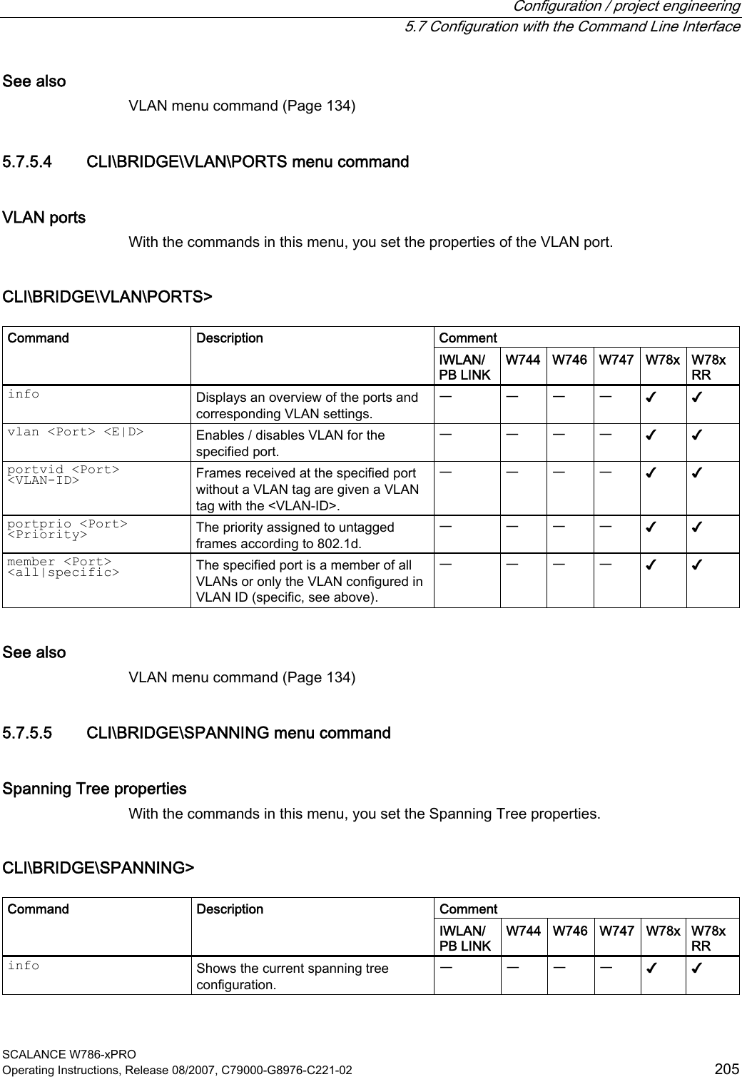
![Configuration / project engineering 5.7 Configuration with the Command Line Interface SCALANCE W786-xPRO Operating Instructions, Release 08/2007, C79000-G8976-C221-02 203 5.7.5 The CLI\BRIDGE menu 5.7.5.1 CLI\BRIDGE menu command Deleting aged bridge information With the command in this menu, you specify the time after which old bridge information in the learning table is deleted. CLI\BRIDGE> Comment Command Description IWLAN/ PB LINK W744 W746 W747 W78x W78x RR Values between 10 s and 1,000,000 s can be set for the aging time. The default value is 300 s (5 min). aging [E|D|aging time] Enables / disables automatic deletion of information on the assignment of MAC addresses and ports. With the Aging time parameter, you can change the time. ᅳ ✔ ✔ ✔ ✔ ✔ learn Displays the learning table. ᅳ ✔ ✔ ✔ ᅳ ᅳ arp Displays the ARP table. ᅳ ✔ ✔ ✔ ✔ ✔ ipmap Displays the IP mapping table ᅳ ✔ ✔ ✔ ᅳ ᅳ STORMTHR Opens the storm threshold menu ᅳ ✔ ✔ ✔ ᅳ ᅳ NAT Opens the NAT menu ᅳ ✔ ✔ ✔ ᅳ ᅳ See also Bridge menu command (Page 131) 5.7.5.2 CLI\BRIDGE\WDS\WLAN1 (or \WLAN2 or \WLAN3) menu command Increasing network span with WDS With the commands in this menu, you set the WDS mode (Wireless Distributed System) to increase the network span or to set up a wireless backbone. CLI\BRIDGE\WDS\WLAN1>-(or \WLAN2 or \WLAN3) Comment Command Description IWLAN/ PB LINK W744 W746 W747 W78x W78x RR edit <Index> [E|D] [SE|SD] [key] Changes the WDS connection specified by Index. With [E|D], you can enable / disable the connection. ᅳ ᅳ ᅳ ᅳ ✔ ✔](https://usermanual.wiki/Siemens/MPCI1V2.Manual/User-Guide-916091-Page-203.png)
![Configuration / project engineering 5.7 Configuration with the Command Line Interface SCALANCE W786-xPRO 204 Operating Instructions, Release 08/2007, C79000-G8976-C221-02 Comment delete <Index> Deletes the connection with the specified index. ᅳ ᅳ ᅳ ᅳ ✔ ✔ clearall Deletes all WDS connections. ᅳ ᅳ ᅳ ᅳ ✔ ✔ See also WDS menu command (Page 132) 5.7.5.3 CLI\BRIDGE\VLAN\VLAN_ID menu command VLAN With the commands in this menu, you specify the VLAN-ID. CLI\BRIDGE\VLAN\VLAN_ID> Comment Command Description IWLAN/ PB LINK W744 W746 W747 W78x W78x RR info Shows the currently configured VLANs and their relationship to the ports. ᅳ ᅳ ᅳ ᅳ ✔ ✔ add <VLAN-ID> [u [ports]] Inserts a new VLAN. Ports: Specifies the port that will be configured for the VLAN. u: The port is a member of the VLAN, frames are sent without a VLAN tag. Examples: add 100 u 2 4 Creates an entry with the VLAN-ID 100. Ports 2 and 4 are members of this VLAN. ᅳ ᅳ ᅳ ᅳ ✔ ✔ edit <VLAN-ID> [- [ports],] [u [ports],] Changes the membership of ports in a VLAN. The parameters correspond to those of the add command. Examples: edit 100 - 2 Port 2 no longer belongs to the VLAN with ID 100. ᅳ ᅳ ᅳ ᅳ ✔ ✔ delete <VLAN-ID> Deletes the VLAN with the specified VLAN ID from the configuration of the SCALANCE W78x. ᅳ ᅳ ᅳ ᅳ ✔ ✔](https://usermanual.wiki/Siemens/MPCI1V2.Manual/User-Guide-916091-Page-204.png)
![Configuration / project engineering 5.7 Configuration with the Command Line Interface SCALANCE W786-xPRO 206 Operating Instructions, Release 08/2007, C79000-G8976-C221-02 Comment spanning [E|D] Enables (E) or disables (D) the (R)STP algorithm. ᅳ ᅳ ᅳ ᅳ ✔ ✔ version [R | S] Specifies whether the Rapid Spanning Tree (R) or Spanning Tree (S) mode is used. ᅳ ᅳ ᅳ ᅳ ✔ ✔ Default value: 32768 bridge [0 ... 61440] This specifies the bridge priority for the SCALANCE W-700: ᅳ ᅳ ᅳ ᅳ ✔ ✔ Default value: 2 s hellotm [1...10] Specifies the interval between two BPDUs in seconds. ᅳ ᅳ ᅳ ᅳ ✔ ✔ Default value: 15 s fwd_delay [4...30] Specifies the delay time for the effectiveness of configuration information (specified in seconds). ᅳ ᅳ ᅳ ᅳ ✔ ✔ Default value: 20 s maxage [6....40] Maximum age for configuration information. (specified in seconds). ᅳ ᅳ ᅳ ᅳ ✔ ✔ See also Spanning Tree menu command (Page 140) 5.7.5.6 CLI\BRIDGE\SPANNING\PORTS menu command Spanning tree port With the commands in this menu, you set the Spanning Tree port properties. CLI\BRIDGE\SPANNING\PORTS> Comment Command Description IWLAN/ PB LINK W744 W746 W747 W78x W78x RR info Displays the current spanning tree configuration. ᅳ ᅳ ᅳ ᅳ ✔ ✔ portstp <E|D> [ports] Enables / disables the spanning tree algorithm for the specified ports. ᅳ ᅳ ᅳ ᅳ ✔ ✔ portprio <Port> [0 ... 240] Specifies the priority of the port. ᅳ ᅳ ᅳ ᅳ ✔ ✔ stp_cost <Port> [1 ... 65535] Specifies the path costs for the port if Version is set to STP. ᅳ ᅳ ᅳ ᅳ ✔ ✔ rstp_cost <Port> [0 ... 200000000] Specifies the path costs for the port if Version is set to RSTP. If the value is 0, the value is calculated. ᅳ ᅳ ᅳ ᅳ ✔ ✔](https://usermanual.wiki/Siemens/MPCI1V2.Manual/User-Guide-916091-Page-206.png)
![Configuration / project engineering 5.7 Configuration with the Command Line Interface SCALANCE W786-xPRO Operating Instructions, Release 08/2007, C79000-G8976-C221-02 207 Comment edgeport <Port> [T|F] Specifies whether or not an edge port (T) or a station (F) that supports spanning tree or rapid spanning tree is attached to this port. if a (rapid) spanning tree protocol is received, the value F is displayed automatically. ᅳ ᅳ ᅳ ᅳ ✔ ✔ The point-to-point link establishes a direct link between two stations. In this case, you have the following options: ᅳ ᅳ ᅳ ᅳ ✔ ✔ O The port recognizes a PtP port based on the duplexity. If the connection is full duplex, it is assumed to be PtP, if it is half duplex, no PtP connection is assumed (shared medium). C Specifies a PtP link, even though half duplex is being used. ptpport <port> <A|T|F>F Specifies that there is no PtP link over the relevant port even with full duplex. See also Spanning Tree menu command (Page 140) 5.7.5.7 CLI\BRIDGE\STORMTHR menu command Storm threshold With the commands in this menu, you set the storm threshold properties. CLI\BRIDGE\STORMTHR> Comment Command Description IWLAN/ PB LINK W744 W746 W747 W78x W78x RR stormthr <E|D> Enables / disables the storm threshold function. ✔ ✔ ✔ ✔ ✔ ✔ broadcast <limit value> Specifies the maximum number of broadcast packets per second from the same address. ✔ ✔ ✔ ✔ ✔ ✔ multicast <limit value> Specifies the maximum number multicast packets per second from the same address. ✔ ✔ ✔ ✔ ✔ ✔](https://usermanual.wiki/Siemens/MPCI1V2.Manual/User-Guide-916091-Page-207.png)
![Configuration / project engineering 5.7 Configuration with the Command Line Interface SCALANCE W786-xPRO 208 Operating Instructions, Release 08/2007, C79000-G8976-C221-02 Comment broad_eth <limit value> Specifies the maximum number of broadcast packets per second for the Ethernet interface. ✔ ✔ ✔ ✔ ✔ ✔ multi_eth <limit value> Specifies the maximum number of multicast packets per second for the Ethernet interface. ✔ ✔ ✔ ✔ ✔ ✔ broad_1 <limit value> broad_2 <limit value> Specifies the maximum number of broadcast packets per second for the first or second wireless interface. ✔ ✔ ✔ ✔ ✔ ✔ multi_1 <limit value> multi_2 <limit value> Specifies the maximum number of multicast packets per second for the first or second wireless interface. ✔ ✔ ✔ ✔ ✔ ✔ See also Storm Threshold menu command (Page 147) 5.7.5.8 CLI\BRIDGE\NAT menu command NAT (Network Address Translation) With the commands in this menu, you set the NAT properties. CLI\BRIDGE>nat Comment Command Description IWLAN/ PB LINK W744 W746 W747 W78x W78x RR nat [E|D] Enables/disables NAT ✔ ✔ ✔ ✔ ✔ ✔ ip [IP address] Sets the local IP address for the Ethernet port ✔ ✔ ✔ ✔ ✔ ✔ subnet [Subnet mask] Sets the subnet mask for the Ethernet port ✔ ✔ ✔ ✔ ✔ ✔ static Opens the "STATIC" menu ✔ ✔ ✔ ✔ ✔ ✔ See also NAT menu command (Page 147) 5.7.5.9 CLI\BRIDGE\NAT\STATIC menu command NAT STATIC With the commands in this menu, you set the NAT STATIC properties.](https://usermanual.wiki/Siemens/MPCI1V2.Manual/User-Guide-916091-Page-208.png)
![Configuration / project engineering 5.7 Configuration with the Command Line Interface SCALANCE W786-xPRO Operating Instructions, Release 08/2007, C79000-G8976-C221-02 209 CLI\BRIDGE\NAT>STATIC Comment Command Description IWLAN/ PB LINK W744 W746 W747 W78x W78x RR Add a static NAT entry: Type TCP or UDP G-Port Global Port L-IP Local IP add <Type> <G-Port> <L-IP> <L-Port> L-Port Local Port ✔ ✔ ✔ ✔ ✔ ✔ Edit a static NAT entry: Index Index in table Type TCP or UDP G-Port Global Port L-IP Local IP edit <Index> <E|D> [type] [G-Port] [L-IP] [L-Port] L-Port Local Port ✔ ✔ ✔ ✔ ✔ ✔ delete <Index> Deletes a static NAT entry ✔ ✔ ✔ ✔ ✔ ✔ clearall Deletes all static NAT entries ✔ ✔ ✔ ✔ ✔ ✔ CLI\BRIDGE\NAT\STATIC>info Index Enabled Type Global Port Local IP Local Port 1 x TCP 21 172.27.138.2 1026 Example of static information See also NAT menu command (Page 147) 5.7.6 The CLI\FILTERS menu 5.7.6.1 CLI\FILTERS\MAC1FLT menu command MAC Filter With the commands in this menu, you set the MAC filter properties.](https://usermanual.wiki/Siemens/MPCI1V2.Manual/User-Guide-916091-Page-209.png)
![Configuration / project engineering 5.7 Configuration with the Command Line Interface SCALANCE W786-xPRO 210 Operating Instructions, Release 08/2007, C79000-G8976-C221-02 CLI\FILTERS\MAC1FLT> Comment Command Description IWLAN/ PB LINK W744 W746 W747 W78x W78x RR fltmac1 <E|D> Enables / disables the filter. ᅳ ᅳ ᅳ ᅳ ✔ ✔ statmac1 [F|B] If the value is set to F (forwarding), only packets with a source address contained in the table are forwarded. In mode B (blocking), these packets are blocked and all others are forwarded. ᅳ ᅳ ᅳ ᅳ ✔ ✔ add <MAC addr.> [description] Adds a new address to the filter list. The optional description has no influence on the list and simply serves as information for the user. ᅳ ᅳ ᅳ ᅳ ✔ ✔ edit <Number|MAC> [E|D] [description] Changes the specified value. ᅳ ᅳ ᅳ ᅳ ✔ ✔ check_wds <E|D> Enables / disables checking including the WDS ports. With the E setting, the WDS ports are also monitored. ᅳ ᅳ ᅳ ᅳ ✔ ✔ delete <Number|MAC> Deletes the entry from the list. ᅳ ᅳ ᅳ ᅳ ✔ ✔ clearall Deletes all entries from the list. ᅳ ᅳ ᅳ ᅳ ✔ ✔ See also MAC Filters menu command (Page 152) 5.7.6.2 CLI\FILTERS\MAC2FLT menu command MAC-dependent communication paths With the commands in this menu, you specify which device (MAC address) can communication with which devices (MAC address). CLI\FILTERS\MAC2FLT> Comment Command Description IWLAN/ PB LINK W744 W746 W747 W78x W78x RR fltmac2 <E|D> Enables / disables the MAC filter. ᅳ ᅳ ᅳ ᅳ ✔ ✔ add <SourceMAC> <DestMAC> Adds a new entry with source and destination address to the filter. ᅳ ᅳ ᅳ ᅳ ✔ ✔ edit <Index> [E|D] [SourceMAC] [DestMAC] Changes the entry specified by Index. With [E|D], you can enable / disable the entry. ᅳ ᅳ ᅳ ᅳ ✔ ✔ delete <Index> Deletes the entry at the specified index position. ᅳ ᅳ ᅳ ᅳ ✔ ✔ clearall Deletes all entries for the MAC filter. ᅳ ᅳ ᅳ ᅳ ✔ ✔](https://usermanual.wiki/Siemens/MPCI1V2.Manual/User-Guide-916091-Page-210.png)
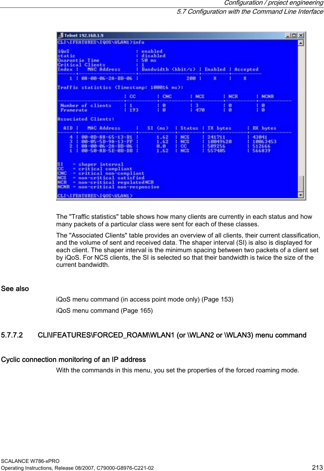
![Configuration / project engineering 5.7 Configuration with the Command Line Interface SCALANCE W786-xPRO Operating Instructions, Release 08/2007, C79000-G8976-C221-02 211 See also MAC Dir Filter menu command (Page 152) 5.7.6.3 CLI\FILTERS\PROTO menu command Protocol filters With the commands in this menu, you set the protocol filter properties. CLI\FILTERS\PROTO> Comment Command Description IWLAN/ PB LINK W744 W746 W747 W78x W78x RR clearall Deletes all entries for the protocol filter. ᅳ ᅳ ᅳ ᅳ ✔ ✔ statprot <F|B> The selected protocols are forwarded / not forwarded. ᅳ ᅳ ᅳ ᅳ ✔ ✔ fltprot <E|D> Enables / disables the protocol filter. ᅳ ᅳ ᅳ ᅳ ✔ ✔ add <Pattern> [description] Adds a new entry. A hexadecimal value is expected for the "Pattern" value. The user can enter a short note for this protocol as the description. ᅳ ᅳ ᅳ ᅳ ✔ ✔ edit <Index> [E|D] [Pattern] [description] Changes of enables / disables the filter entry. ᅳ ᅳ ᅳ ᅳ ✔ ✔ delete <Index> Deletes the filter entry. ᅳ ᅳ ᅳ ᅳ ✔ ✔ clearall Deletes all entries from the table. ᅳ ᅳ ᅳ ᅳ ✔ ✔ See also Protocol Filter menu command (Page 152) 5.7.7 The CLI\IFEATURES menu 5.7.7.1 CLI\IFEATURES\IQOS\WLAN1 (or \WLAN2 or \WLAN3) menu command Note This function is not available in firmware version 3.2.](https://usermanual.wiki/Siemens/MPCI1V2.Manual/User-Guide-916091-Page-211.png)
![Configuration / project engineering 5.7 Configuration with the Command Line Interface SCALANCE W786-xPRO 212 Operating Instructions, Release 08/2007, C79000-G8976-C221-02 Client-specific bandwidth reservation - Quality of Service (iQoS) With the commands in this menu, you set the properties of the iQOS mode or obtain information on iQoS. CLI\IFEATURE\IQOS\WLAN1> (or \WLAN2 or \WLAN3) Comment Command Description IWLAN/ PB LINK W744 W746 W747 W78x W78xRR iqos [E|D] Enables / disables iQOS functionality. ᅳ ᅳ ᅳ ᅳ ✔ ✔ static [E|D] Enables / disables the calculation of the minimum transmission rate. ᅳ ᅳ ᅳ ᅳ ✔ ✔ 15 – 1000 ms, default 50 ms response [response time] Specifies the response time for a client with bandwidth reservation. ᅳ ᅳ ᅳ ᅳ ✔ ✔ add <MAC> <Max_BW> [E|D] Creating a critical client. ᅳ ᅳ ᅳ ᅳ ✔ ✔ edit <Index> <Max_BW> <E|D> Changes the setting of a client ᅳ ᅳ ᅳ ᅳ ✔ ✔ delete <Index> Deletes a critical client ᅳ ᅳ ᅳ ᅳ ✔ ✔ clearall Deletes all critical clients ᅳ ᅳ ᅳ ᅳ ✔ ✔ info Displays information on iQos. ᅳ ᅳ ᅳ ᅳ ✔ ✔ The CLI also supplies detailed information on iQoS. In this view, the first part displays the current configuration, in other words whether iQoS is enabled, , whether the calculations and reservations are based on the static "worst-case" assumptions (static = enabled) or the current situation (static = disabled). The number of configured critical clients is also displayed.](https://usermanual.wiki/Siemens/MPCI1V2.Manual/User-Guide-916091-Page-212.png)
![Configuration / project engineering 5.7 Configuration with the Command Line Interface SCALANCE W786-xPRO 214 Operating Instructions, Release 08/2007, C79000-G8976-C221-02 CLI\IFEATURES\FORCED_ROAM\WLAN1> (or \WLAN2 or \WLAN3) Comment Command Description IWLAN/ PB LINK W744 W746 W747 W78x W78x RR froam [E|D] Enables of disables forced roaming on IP down. ᅳ ᅳ ᅳ ᅳ ✔ ✔ ip [IP address] Monitors the connection to this IP partner. ᅳ ᅳ ᅳ ᅳ ✔ ✔ interval [100 - 5000] Specifies the monitoring cycles to the IP partner in milliseconds. ᅳ ᅳ ᅳ ᅳ ✔ ✔ lostpkts [1 - 5] Specifies the maximum number of unanswered pings before the WLAN interface is disabled. ᅳ ᅳ ᅳ ᅳ ✔ ✔ See also Forced Roaming on IP Down menu command (in access point mode only) (Page 154) 5.7.7.3 CLI\IFEATURES\LINKCHECK menu command Device-related connection monitoring With the commands in this menu, you set the properties of device-related connection monitoring. CLI\IFEATURES\LINKCHECK> Comment Command Description IWLAN/ PB LINK W744 W746 W747 W78x W78x RR linkchk [E|D] Enable / disable device-related connection monitoring. ᅳ ᅳ ᅳ ᅳ ✔ ✔ add <MAC> [timeout] Adds a new MAC address for connection monitoring and specifies the monitoring time. No time is specified, the default is 500 ms. ᅳ ᅳ ᅳ ᅳ ✔ ✔ edit <Index|MAC> [E|D] [timeout] Modifies, enables, or disables an entry. ᅳ ᅳ ᅳ ᅳ ✔ ✔ delete <Index|MAC> Deletes the specified entry from the list. ᅳ ᅳ ᅳ ᅳ ✔ ✔ clearall Deletes all entries for connection monitoring. ᅳ ᅳ ᅳ ᅳ ✔ ✔ acknow [Index|All] Displays or acknowledges (clears) the Link Check messages requiring acknowledgment. The fault state remains active until all the fault messages have been acknowledged. The fault status and the LED are cleared if the reason for the fault status was only a link check error message.](https://usermanual.wiki/Siemens/MPCI1V2.Manual/User-Guide-916091-Page-214.png)
![Configuration / project engineering 5.7 Configuration with the Command Line Interface SCALANCE W786-xPRO Operating Instructions, Release 08/2007, C79000-G8976-C221-02 215 Comment ᅳ ᅳ ᅳ ᅳ ✔ ✔ See also Link Check menu command (in access point mode only) (Page 154) 5.7.7.4 CLI\IFEATURES\REDUNDANCY menu command Redundant connection With the commands in this menu, you set the properties of the redundant connection between two devices. CLI\IFEATURES\REDUNDANCY> Comment Command Description IWLAN/ PB LINK W744 W746 W747 W78x W78x RR redun [E|D] Enables / disables the redundancy function ᅳ ᅳ ᅳ ᅳ ✔ ✔ wep [E|D] Enables / disables encryption. ᅳ ᅳ ᅳ ᅳ ✔ ✔ mac1 <MAC address> Specifies the device that will be operated redundantly along with the first wireless adapter. ᅳ ᅳ ᅳ ᅳ ✔ ✔ mac2 <MAC address> Specifies the device that will be operated redundantly along with the second wireless adapter. ᅳ ᅳ ᅳ ᅳ ✔ ✔ name [system name] Instead of the MAC addresses, you can also specify the sysName of the device. ᅳ ᅳ ᅳ ᅳ ✔ ✔ wepkey1 [key index] Specifies the WEP key of the device that will be operated redundantly along with the first wireless adapter. ᅳ ᅳ ᅳ ᅳ ✔ ✔ wepkey2 [key index] Specifies the WEP key of the device that will be operated redundantly along with the second wireless adapter. ᅳ ᅳ ᅳ ᅳ ✔ ✔ See also Redundancy menu command (in access point mode only) (Page 155)](https://usermanual.wiki/Siemens/MPCI1V2.Manual/User-Guide-916091-Page-215.png)
![Configuration / project engineering 5.7 Configuration with the Command Line Interface SCALANCE W786-xPRO 216 Operating Instructions, Release 08/2007, C79000-G8976-C221-02 5.7.7.5 CLI\IFEATURES\IP_ALIVE menu command Application-related connection monitoring With the commands in this menu, you set the properties of application-related connection monitoring. CLI\IFEATURES\IP_ALIVE> Comment Command Description IWLAN/ PB LINK W744 W746 W747 W78x W78x RR ipalive <E|D> Enables / disables application-related connection monitoring. ᅳ ᅳ ᅳ ᅳ ✔ ✔ add <E|D> <IP address> <:Port> <Timeout> Adds a new IP address to the connection monitoring and enables / disables monitoring for this IP address.ᅳ ᅳ ᅳ ᅳ ✔ ✔ edit <Index|IP addr.> [:port] [E|D] [timeout] Modifies, enables, or disables the entry specified by the index or IP address. ᅳ ᅳ ᅳ ᅳ ✔ ✔ delete <Index|IP addr. Deletes the node to be monitored. ᅳ ᅳ ᅳ ᅳ ✔ ✔ clearall Deletes all entries for connection monitoring. ᅳ ᅳ ᅳ ᅳ ✔ ✔ The fault state remains active until all the fault messages have been acknowledged. The fault state and the Fault LED are cleared if the only reason was an IP Alive error message. The command is not visible in the client mode. acknow [Index|All] Displays or acknowledges (clears) the IP Alive messages requiring acknowledgment. ᅳ ᅳ ᅳ ᅳ ✔ ✔ See also IP Alive menu command (in access point mode only) (Page 156) 5.7.8 The CLI\INFORM menu 5.7.8.1 CLI\INFORM menu command System events and information on the protocols The pages of this menu provide information on system events and protocols.](https://usermanual.wiki/Siemens/MPCI1V2.Manual/User-Guide-916091-Page-216.png)
![Configuration / project engineering 5.7 Configuration with the Command Line Interface SCALANCE W786-xPRO Operating Instructions, Release 08/2007, C79000-G8976-C221-02 217 CLI\INFORM> Comment Command Description IWLAN/ PB LINK W744 W746 W747 W78x W78x RR This can be called in every submenu. info Displays information on the current menu item. ✔ ✔ ✔ ✔ ✔ ✔ WLAN1 Opens the WLAN menu ✔ ✔ ✔ ✔ ᅳ ᅳ ETHERNET Opens the ETHERNET menu ᅳ ✔ ✔ ✔ ᅳ ᅳ LOG Opens the LOG menu ✔ ✔ ✔ ✔ ᅳ ᅳ AUTHLOG Opens the AUTHLOG menu ✔ ✔ ✔ ✔ ᅳ ᅳ SIGNAL Open the signal recorder menu ✔ ✔ ✔ ✔ ᅳ ᅳ spanning Displays information on spanning tree ᅳ ᅳ ᅳ ᅳ ✔ ✔ See also Information menu command (Page 157) 5.7.8.2 CLI\INFORM\LOG menu command System events and information on the protocols The pages of this menu display tables contain information on system events and on the behavior of the protocols (IP, TCP, UDP, and ICMP, SNMP). CLI\INFORM\LOG> Comment Command Description IWLAN/ PB LINK W744 W746 W747 W78x W78x RR events <show | clear> Displays or deletes the log table. ✔ ✔ ✔ ✔ ✔ ✔ addevent <Text> Adds an event to the log table. ✔ ✔ ✔ ✔ ✔ ✔ The default is 400. eventmax [Max count] Sets the maximum number of log entries. ✔ ✔ ✔ ✔ ✔ ✔ See also Log Table menu command (Page 157)](https://usermanual.wiki/Siemens/MPCI1V2.Manual/User-Guide-916091-Page-217.png)
![Configuration / project engineering 5.7 Configuration with the Command Line Interface SCALANCE W786-xPRO 218 Operating Instructions, Release 08/2007, C79000-G8976-C221-02 5.7.8.3 CLI\INFORM\AUTHLOG menu command Logging authentication The pages of this menu contain a table with information on successful or failed authentication attempts. CLI\INFORM\AUTHLOG> Comment Command Description IWLAN/ PB LINK W744 W746 W747 W78x W78x RR Displays the authentication entries. By specifying a parameter, the display can be limited to specific information: 0 All 1 Good 2 All Errors 3 802.11 Errors 4 ACL Errors 5 RADIUS Errors (request denied, password rejected etc.) 6 802.1x Errors (timeout, no response from RADIUS or WPA server) 7 Deauthenticated Errors show [0...8] 8 Deassociated errors ✔ ✔ ✔ ✔ ✔ ✔ clear Deletes all entries. ✔ ✔ ✔ ✔ ✔ ✔ See also Auth Log menu command (Page 157) 5.7.8.4 CLI\INFORM\WLAN1 (or \WLAN2 or \WLAN3) menu command Logged-on clients All the logged-on clients along with certain additional information (wireless channel, status etc.) are displayed here.](https://usermanual.wiki/Siemens/MPCI1V2.Manual/User-Guide-916091-Page-218.png)
![Configuration / project engineering 5.7 Configuration with the Command Line Interface SCALANCE W786-xPRO Operating Instructions, Release 08/2007, C79000-G8976-C221-02 219 CLI\INFORM\WLANx> Comment Command Description IWLAN/ PB LINK W744 W746 W747 W78x W78x RR Station Displays information on the connected stations. ✔ ✔ ✔ ✔ ✔ ✔ resetStats Resets the statistics that are displayed with the Station command. ✔ ✔ ✔ ✔ ✔ ✔ (only in access point mode) Apinfo Displays information on the access point. ᅳ ᅳ ᅳ ᅳ ✔ ✔ Scan Displays all the access points in the area. Possible only if iPCF is disabled. ✔ ✔ ✔ ✔ ✔ ✔ Noise Shows disturbances on the individual channels. ✔ ✔ ✔ ✔ ✔ ✔ stasort Displays information on the available access points sorted according to MAC addresses or signal strength. ✔ ✔ ✔ ✔ ᅳ ᅳ scanww Displays all access points regardless of the country code. ᅳ ✔ ✔ ✔ ✔ ✔ vap Displays all configured SSIDs (VAPs). ᅳ ᅳ ᅳ ᅳ ✔ ✔ overlap Shows the access points on the set or adjacent channels. ᅳ ᅳ ᅳ ᅳ ✔ ✔ over_age [1..7200] Changes the aging interval (in minutes) for the list of neighboring access points. If an AP is inactive for longer than the time set here, it is removed from the list. ᅳ ᅳ ᅳ ᅳ ✔ ✔ See also Client List menu command (Page 159) 5.7.8.5 CLI\INFORM\SIGNAL menu command Display of the current signal strength and recording of a series of measurements With the commands in this menu, you set the properties of the signal recorder. CLI\INFORM\SIGNAL> Comment Command Description IWLAN/ PB LINK W744 W746 W747 W78x W78x RR recstart <interval> [number of recording points] Starts signal recording. This command is only available in the client mode.](https://usermanual.wiki/Siemens/MPCI1V2.Manual/User-Guide-916091-Page-219.png)
![Configuration / project engineering 5.7 Configuration with the Command Line Interface SCALANCE W786-xPRO 220 Operating Instructions, Release 08/2007, C79000-G8976-C221-02 Comment The interval at which the current signal is recorded can be between 1 and 1000 milliseconds. A value between 1 and 20000 is possible for the number of recording points. ✔ ✔ ✔ ✔ ✔ ✔ This command is only available in the client mode. recstop Stops signal recording prematurely. ✔ ✔ ✔ ✔ ✔ ✔ This command is only available in the client mode. dispstart [interval] Displays the current signal strength cyclically on the CLI. The interval can be between 100 and 10000 milliseconds ✔ ✔ ✔ ✔ ✔ ✔ This command is only available in the client mode. dispstop Stars cyclic output of the signal strength. ✔ ✔ ✔ ✔ ✔ ✔ This command is only available in client mode exit Closes the CLI/TELNET connection. ✔ ✔ ✔ ✔ ✔ ✔ This command is only available in client mode info Displays the parameters of the signal recorder ✔ ✔ ✔ ✔ ✔ ✔ See also Signal Recorder menu command (Page 167)](https://usermanual.wiki/Siemens/MPCI1V2.Manual/User-Guide-916091-Page-220.png)
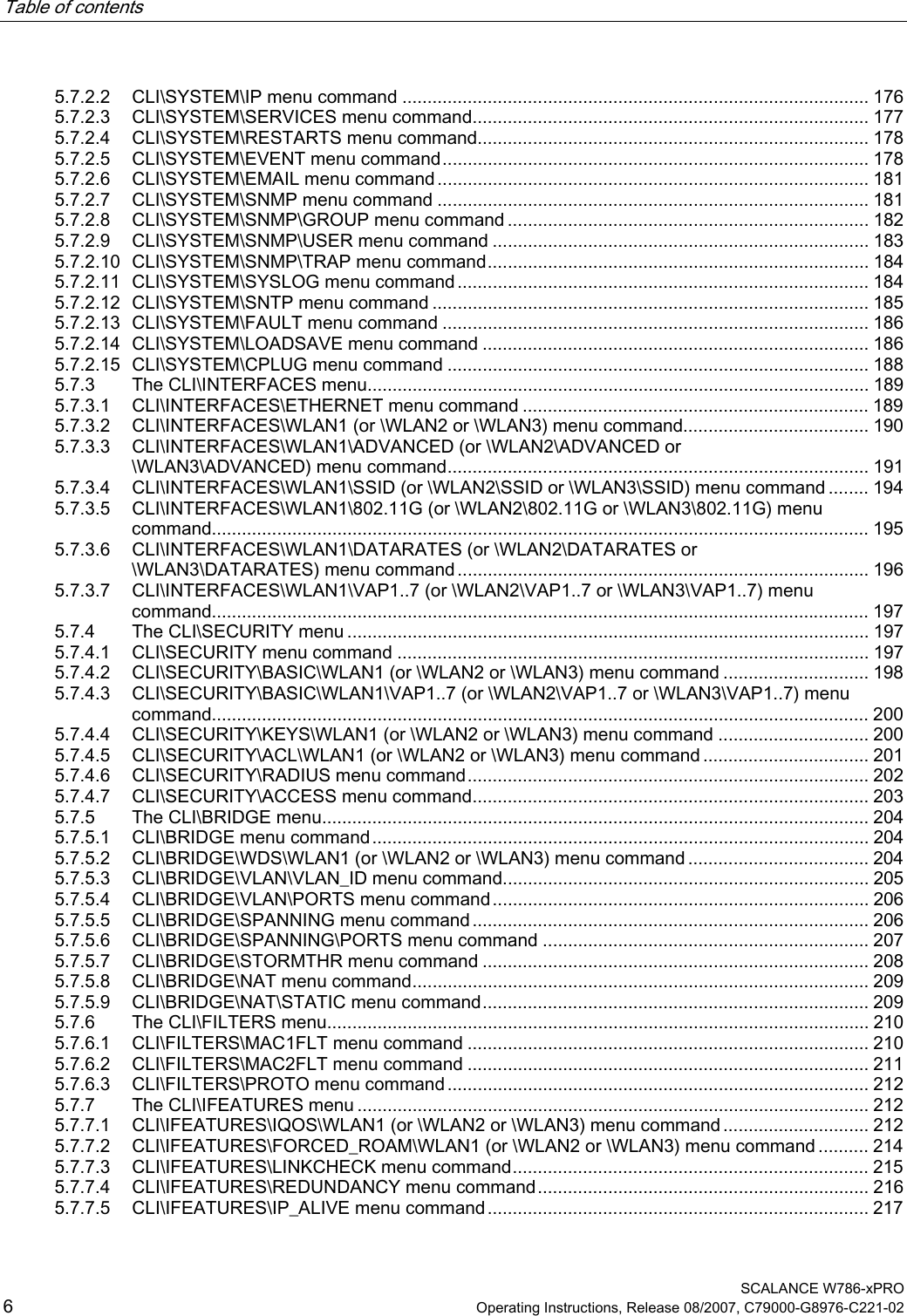
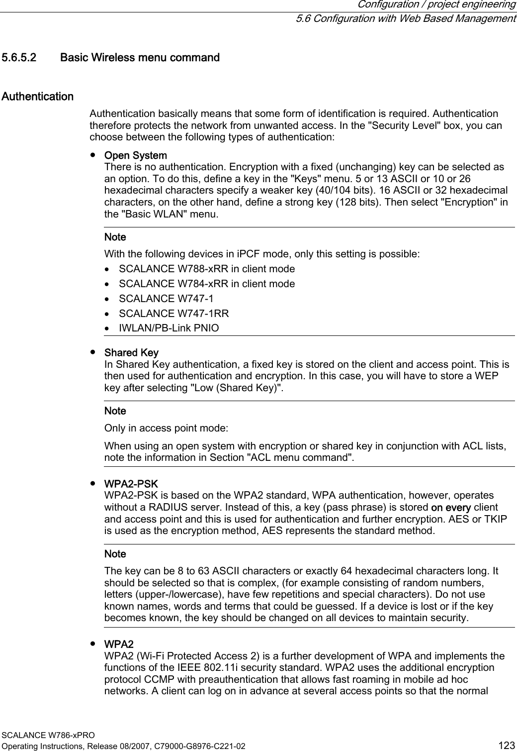
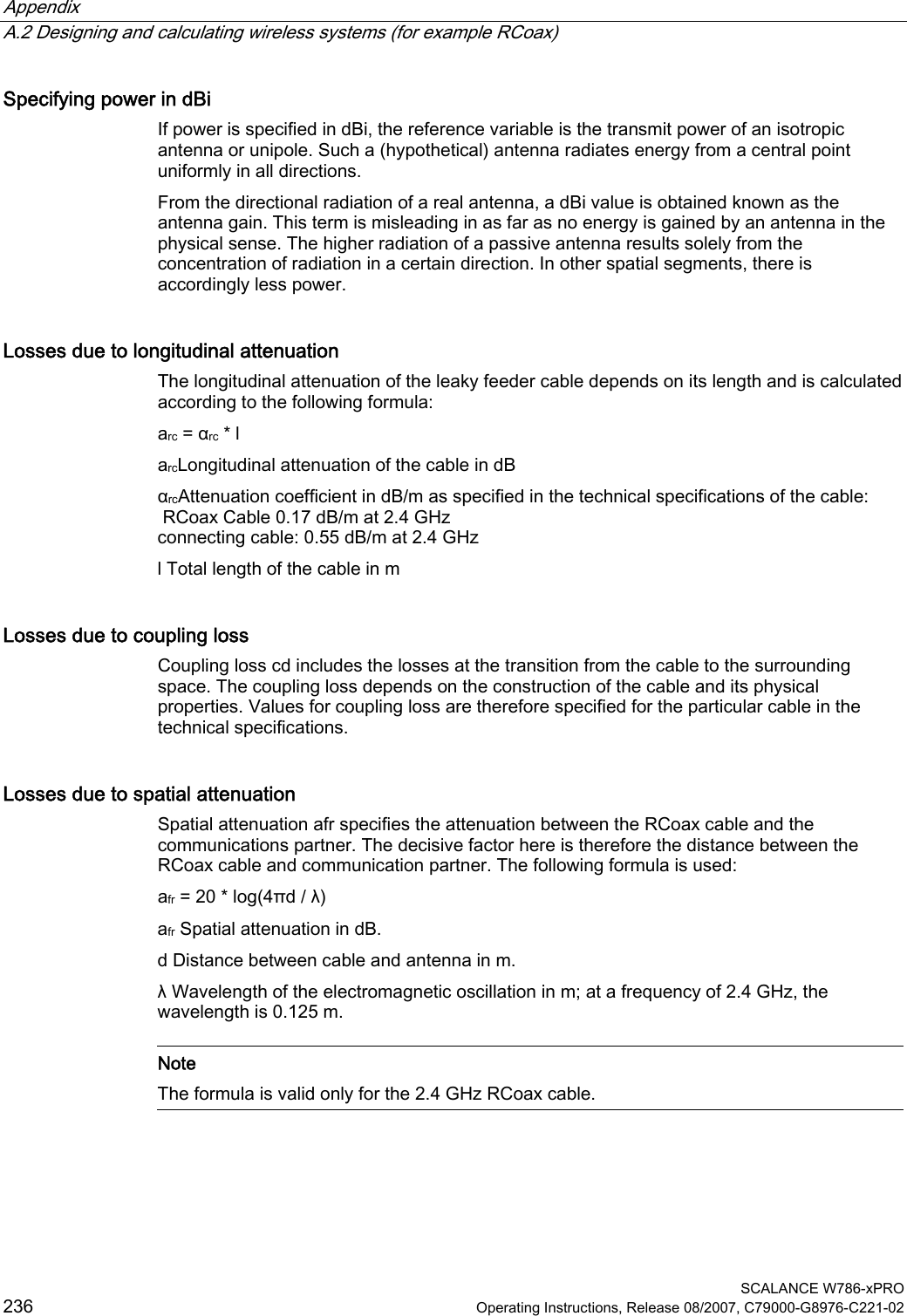
![Appendix A.2 Designing and calculating wireless systems (for example RCoax) SCALANCE W786-xPRO 234 Operating Instructions, Release 08/2007, C79000-G8976-C221-02 A.2 Designing and calculating wireless systems (for example RCoax) Decibels as a logarithmic unit of measure In wireless technology, most calculations are made in decibels (dB). Decibel means the logarithm of a ratio. Formulated mathematically, this can be shown by the following equation: Decibel value = 10 * log (ratio) Using sample calculations, the following decibel values are obtained: Ratio Decibel value 0,001 -30 dB 0,1 -10 dB 0,2 -7 dB 0,4 -4 dB 0,5 -3 dB 1 0 dB 2 3 dB 4 6 dB As can be seen in the example, halving a value reduces the decibel value by 3 dB. This remains true regardless of the selected reference variable because only the ratio counts. Which reference variable is used can be recognized by the additional letters or numbers following the dimension dB. In acoustics, for example, the threshold of audibility is the reference variable for a value in dB(A). Specifying power in dBm A commonly used reference variable in wireless technology is a power of 1 mW. Power can then be specified in the decibel milliwatt unit (dBm). The following formula is used: P [dBm] = 10 * log (P [mW] / 1 mW) This results in the following power specifications in dBm: Power value Decibel value 0.5 mW ≈ -3 dBm 1 mW ≈ 0 dBm 2 mW ≈ 3 dBm 4 mW ≈ 6 dBm 10 mW ≈ 10 dBm 100 mW ≈ 20 dBm 200 mW ≈ 23 dBm 1000 mW ≈ 30 dBm](https://usermanual.wiki/Siemens/MPCI1V2.Manual/User-Guide-916091-Page-234.png)
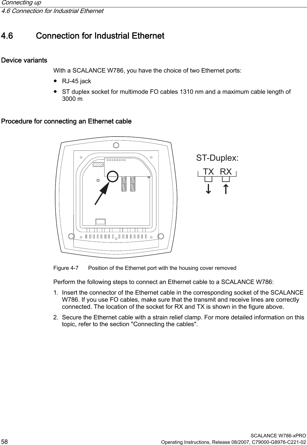
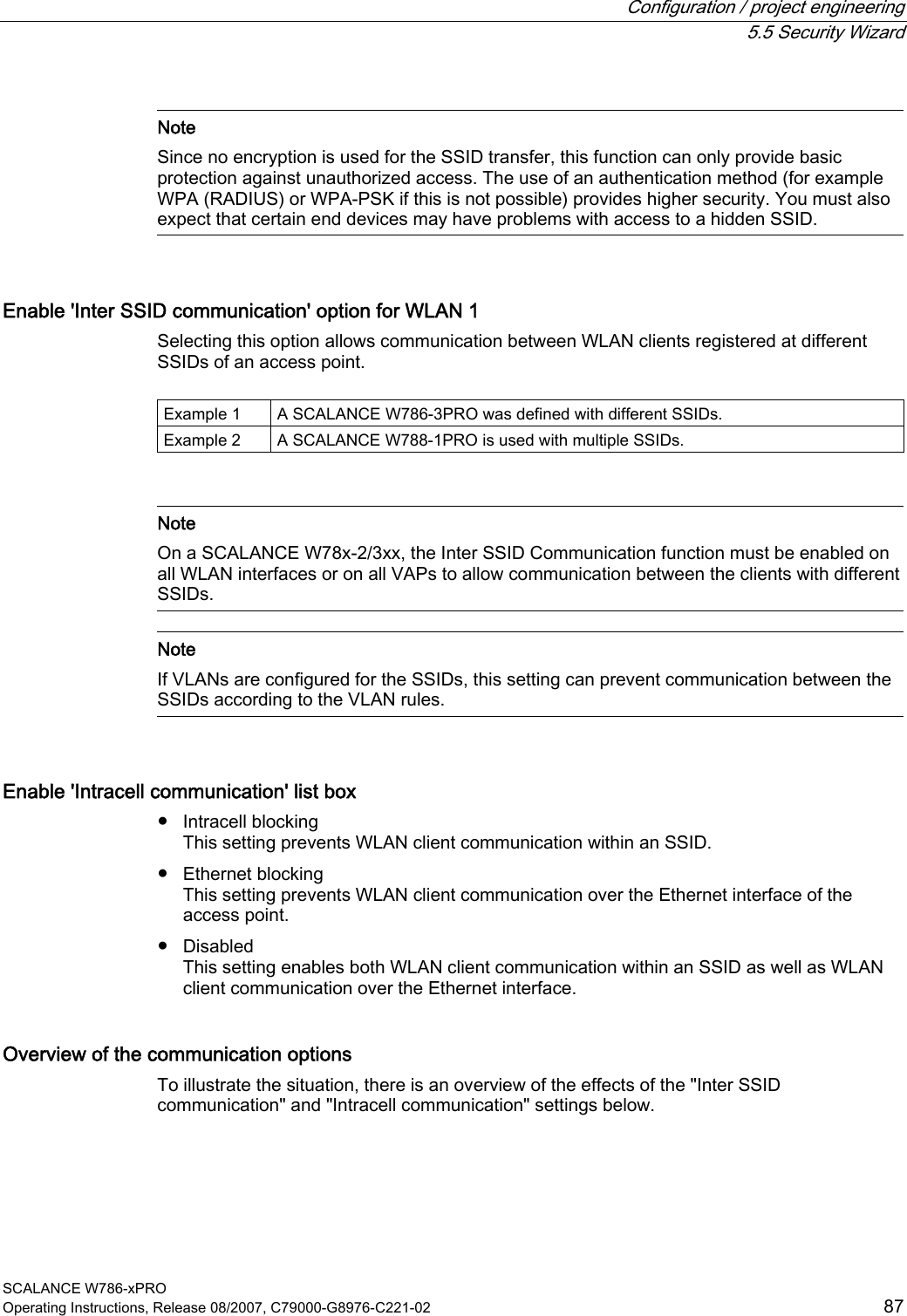
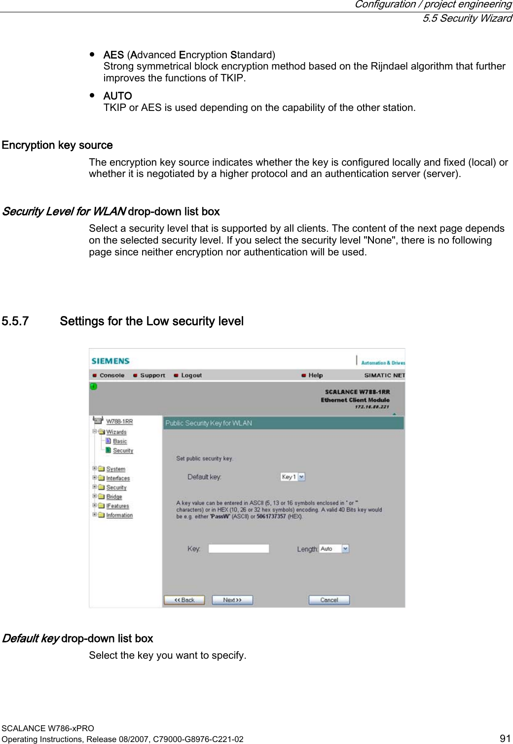
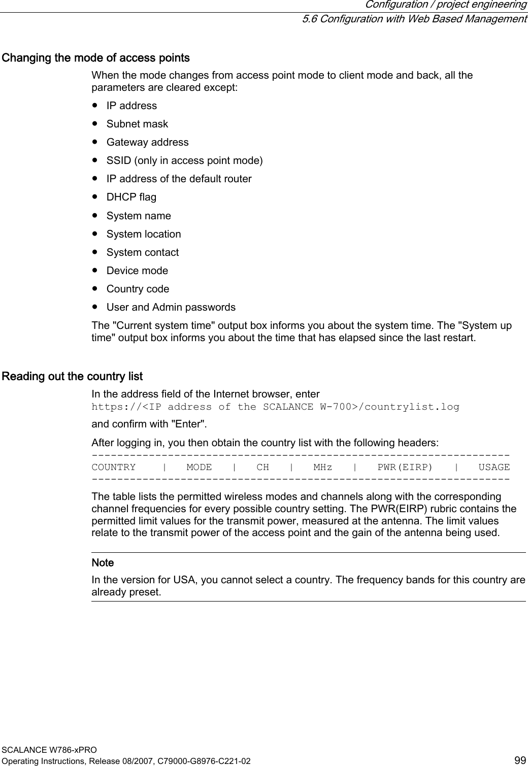
![Appendix A.2 Designing and calculating wireless systems (for example RCoax) SCALANCE W786-xPRO Operating Instructions, Release 08/2007, C79000-G8976-C221-02 235 Using power specifications, it is simple to calculate gain and attenuation. To calculate an entire system, the individual values for gain and attenuation must simply be added. Transmit power in dBm The information in the following tables applies to the following SIMATIC NET products: ● Access Point SCALANCE W786-1PRO ● Access Point SCALANCE W786-2PRO ● Access Point SCALANCE W786-3PRO Table A-1 Transmit power in IEEE 802.11b mode (2.4 GHz) Data rate [Mbps] P0 [dBm] 1 20 2 20 5,5 20 11 20 Table A-2 Transmit power in IEEE 802.11g mode (2.4 GHz) Data rate [Mbps] P0 [dBm] 6 20 9 20 12 20 18 20 24 20 36 20 48 20 54 19 Table A-3 Transmit power in IEEE 802.11a/h mode (5 GHz) Data rate [Mbps] P0 [dBm] 6 20 9 20 12 20 18 20 24 20 36 20 48 20 54 19](https://usermanual.wiki/Siemens/MPCI1V2.Manual/User-Guide-916091-Page-235.png)
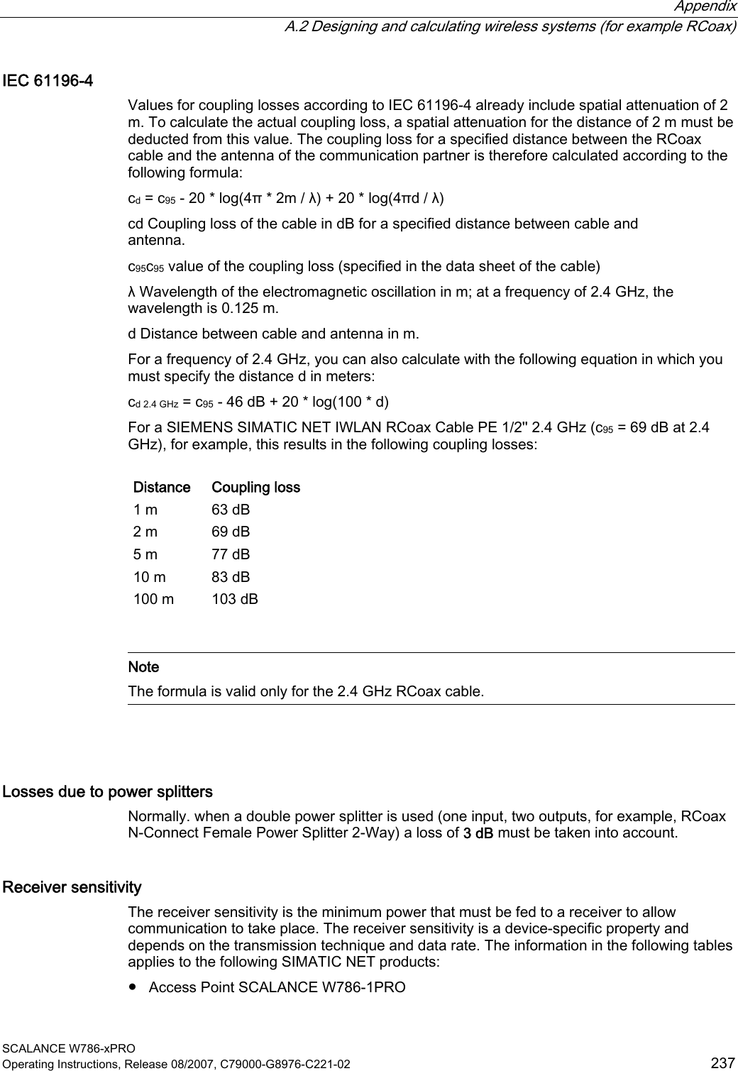
![Appendix A.2 Designing and calculating wireless systems (for example RCoax) SCALANCE W786-xPRO 238 Operating Instructions, Release 08/2007, C79000-G8976-C221-02 ● Access Point SCALANCE W786-2PRO ● Access Point SCALANCE W786-3PRO Table A-4 Receiver sensitivity in IEEE 802.11b mode (2.4 GHz) Data rate [Mbps] Pe [dBm] 1 -97 2 -93 5,5 -92 11 -88 Table A-5 Receiver sensitivity in IEEE 802.11g mode (2.4 GHz) Data rate [Mbps] Pe [dBm] 6 -91 9 -90 12 -89 18 -87 24 -84 36 -80 48 -76 54 -74 Table A-6 Receiver sensitivity in IEEE 802.11a/h mode (5 GHz) Data rate [Mbps] Pe [dBm] 6 -91 9 -90 12 -90 18 -88 24 -85 36 -82 48 -76 54 -72 72 [*] -76 96 [*] -71 108 [*] -68 [*] Turbo mode](https://usermanual.wiki/Siemens/MPCI1V2.Manual/User-Guide-916091-Page-238.png)