Siemens MPCI1V2 Wireless LAN Access Point Module User Manual SCALANCE W786 xPRO
Siemens AG Wireless LAN Access Point Module SCALANCE W786 xPRO
Siemens >
Contents
Manual

Introduction
1
Description
2
Assembly
3
Connecting up
4
Configuration / project
engineering
5
Upkeep and maintenance
6
Technical specifications
7
Appendix
A
SIMATIC NET
SCALANCE W786-xPRO
Operating Instructions
Release 08/2007
C79000-G8976-C221-02

Safety Guidelines
This manual contains notices you have to observe in order to ensure your personal safety, as well as to prevent
damage to property. The notices referring to your personal safety are highlighted in the manual by a safety alert
symbol, notices referring only to property damage have no safety alert symbol. These notices shown below are
graded according to the degree of danger.
DANGER
indicates that death or severe personal injury will result if proper precautions are not taken.
WARNING
indicates that death or severe personal injury may result if proper precautions are not taken.
CAUTION
with a safety alert symbol, indicates that minor personal injury can result if proper precautions are not taken.
CAUTION
without a safety alert symbol, indicates that property damage can result if proper precautions are not taken.
NOTICE
indicates that an unintended result or situation can occur if the corresponding information is not taken into
account.
If more than one degree of danger is present, the warning notice representing the highest degree of danger will
be used. A notice warning of injury to persons with a safety alert symbol may also include a warning relating to
property damage.
Qualified Personnel
The device/system may only be set up and used in conjunction with this documentation. Commissioning and
operation of a device/system may only be performed by qualified personnel. Within the context of the safety notes
in this documentation qualified persons are defined as persons who are authorized to commission, ground and
label devices, systems and circuits in accordance with established safety practices and standards.
Prescribed Usage
Note the following:
WARNING
This device may only be used for the applications described in the catalog or the technical description and only
in connection with devices or components from other manufacturers which have been approved or
recommended by Siemens. Correct, reliable operation of the product requires proper transport, storage,
positioning and assembly as well as careful operation and maintenance.
Trademarks
All names identified by ® are registered trademarks of the Siemens AG. The remaining trademarks in this
publication may be trademarks whose use by third parties for their own purposes could violate the rights of the
owner.
Disclaimer of Liability
We have reviewed the contents of this publication to ensure consistency with the hardware and software
described. Since variance cannot be precluded entirely, we cannot guarantee full consistency. However, the
information in this publication is reviewed regularly and any necessary corrections are included in subsequent
editions.
Siemens AG
Automation and Drives
Postfach 48 48
90327 NÜRNBERG
GERMANY
Ordernumber: C79000-G8976-C221-02
Ⓟ 08/2007
Copyright © Siemens AG 2007.
Technical data subject to change
SCALANCE W786-xPRO
Operating Instructions, Release 08/2007, C79000-G8976-C221-02 3
Table of contents
1 Introduction................................................................................................................................................ 9
1.1 Information on the Operating Instructions SCALANCE W786-xPRO............................................9
1.2 Type designations........................................................................................................................11
2 Description............................................................................................................................................... 13
2.1 Network structures .......................................................................................................................13
2.2 Scope of delivery .........................................................................................................................19
2.3 Product properties........................................................................................................................20
2.4 LED display..................................................................................................................................23
2.5 C-PLUG........................................................................................................................................26
2.6 Reset button.................................................................................................................................27
2.7 Biological compatibility.................................................................................................................28
3 Assembly................................................................................................................................................. 29
3.1 Removing / fitting the housing cover............................................................................................29
3.2 Connecting up cables ..................................................................................................................31
3.3 Mounting without an adapter (wall mounting only) ......................................................................34
3.4 Mounting with mounting plate ......................................................................................................37
3.4.1 Fitting the mounting plate to a wall ..............................................................................................37
3.4.2 Screwing the cover plate for the cable feedthrough to the mounting plate .................................38
3.4.3 Fitting the mounting plate to an S7-300 standard rail..................................................................40
3.4.4 Fitting the mounting plate to a DIN rail ........................................................................................41
3.4.5 Fitting the mounting plate to a mast.............................................................................................42
3.4.6 Fitting/removing the SCALANCE W786 to/from a mounting plate ..............................................43
4 Connecting up ......................................................................................................................................... 45
4.1 Lightning protection, power supply, and grounding .....................................................................45
4.2 Suitable cables and antennas for the SCALANCE W786 ...........................................................47
4.3 Connecting the cables .................................................................................................................49
4.4 Connectors for the power supply of the SCALANCE W786 ........................................................53
4.5 Connecting a power supply adapter ............................................................................................55
4.6 Connection for Industrial Ethernet ...............................................................................................58
4.7 Connectors for external antennas................................................................................................59
4.8 Inserting / removing the C-PLUG.................................................................................................60
5 Configuration / project engineering .......................................................................................................... 61
5.1 Technical basics ..........................................................................................................................61
5.1.1 Spanning Tree .............................................................................................................................61

Table of contents
SCALANCE W786-xPRO
4 Operating Instructions, Release 08/2007, C79000-G8976-C221-02
5.1.2 iQoS ............................................................................................................................................ 62
5.1.3 Forced Roaming on IP Down...................................................................................................... 62
5.1.4 Link Check................................................................................................................................... 62
5.1.5 Redundancy ................................................................................................................................ 62
5.1.6 IP-Alive........................................................................................................................................ 63
5.1.7 MAC-based communication ........................................................................................................ 63
5.1.8 IP-based communication............................................................................................................. 64
5.2 Assignment of an IP address ...................................................................................................... 65
5.2.1 Structure of an IP address .......................................................................................................... 65
5.2.2 Initial assignment of an IP address ............................................................................................. 66
5.2.3 Address assignment with DHCP................................................................................................. 66
5.2.4 Address assignment with the Primary Setup Tool ...................................................................... 67
5.3 The wizards of Web Based Management................................................................................... 68
5.3.1 Introduction ................................................................................................................................. 68
5.3.2 Starting Web Based Management and logging on ..................................................................... 68
5.3.3 Selecting the wizards .................................................................................................................. 70
5.4 Basic Wizard ............................................................................................................................... 72
5.4.1 IP settings.................................................................................................................................... 72
5.4.2 System name .............................................................................................................................. 73
5.4.3 Country code............................................................................................................................... 74
5.4.4 Wireless settings in access point mode ...................................................................................... 75
5.4.5 Wireless settings in client mode.................................................................................................. 76
5.4.6 Adopt MAC Address settings (only for clients or access points in client mode)......................... 76
5.4.7 Channel settings (in access point mode only) ............................................................................ 79
5.4.8 Closing the Basic Wizard ............................................................................................................ 81
5.5 Security Wizard ........................................................................................................................... 82
5.5.1 Introduction ................................................................................................................................. 82
5.5.2 Security settings.......................................................................................................................... 82
5.5.3 Security settings for the management interfaces........................................................................ 83
5.5.4 Security settings for the SNMP protocol ..................................................................................... 84
5.5.5 Security settings for WLAN (page 1, only in access point mode) ............................................... 85
5.5.6 Security settings for WLAN (page 2)........................................................................................... 88
5.5.7 Settings for the Low security level .............................................................................................. 91
5.5.8 Settings for the Medium security level ........................................................................................ 92
5.5.9 Settings for the High security level in access point mode........................................................... 93
5.5.10 Settings for the High security level in "Client" mode................................................................... 94
5.5.11 Overview of the selected security settings for an access point .................................................. 95
5.5.12 Exiting the Security Wizard ......................................................................................................... 96
5.6 Configuration with Web Based Management.............................................................................. 97
5.6.1 General information on Web Based Management...................................................................... 97
5.6.2 The LED simulation of Web Based Management....................................................................... 98
5.6.3 The System menu ....................................................................................................................... 98
5.6.3.1 System Information menu command .......................................................................................... 98
5.6.3.2 IP Settings menu command...................................................................................................... 100
5.6.3.3 Services menu command.......................................................................................................... 100
5.6.3.4 Restart menu command............................................................................................................ 101
5.6.3.5 Event Config menu command................................................................................................... 102
5.6.3.6 E-mail Config menu command.................................................................................................. 103
5.6.3.7 SNMP Config menu command ................................................................................................. 103
5.6.3.8 SSyslog menu command .......................................................................................................... 104
5.6.3.9 SNTP Config menu command .................................................................................................. 106
5.6.3.10 Fault State menu command...................................................................................................... 106
5.6.3.11 Load & Save menu command................................................................................................... 106

Table of contents
SCALANCE W786-xPRO
Operating Instructions, Release 08/2007, C79000-G8976-C221-02 5
5.6.3.12 C-PLUG menu command...........................................................................................................108
5.6.4 The Interfaces menu ..................................................................................................................112
5.6.4.1 Interfaces menu command ........................................................................................................112
5.6.4.2 Ethernet menu command...........................................................................................................113
5.6.4.3 WLAN menu command..............................................................................................................113
5.6.4.4 Advanced menu command ........................................................................................................116
5.6.4.5 SSID List menu command .........................................................................................................120
5.6.4.6 Advanced G menu command ....................................................................................................120
5.6.4.7 Data Rates menu command ......................................................................................................121
5.6.4.8 VAP menu command .................................................................................................................122
5.6.5 The Security menu.....................................................................................................................123
5.6.5.1 Security menu command ...........................................................................................................123
5.6.5.2 Basic Wireless menu command.................................................................................................123
5.6.5.3 Keys menu command ................................................................................................................128
5.6.5.4 ACL menu command .................................................................................................................128
5.6.5.5 RADIUS Server menu command...............................................................................................130
5.6.5.6 Access menu command.............................................................................................................131
5.6.6 The Bridge menu .......................................................................................................................131
5.6.6.1 Bridge menu command..............................................................................................................131
5.6.6.2 WDS menu command................................................................................................................132
5.6.6.3 VLAN menu command...............................................................................................................134
5.6.6.4 Learning Table menu command ................................................................................................140
5.6.6.5 ARP Table menu command.......................................................................................................140
5.6.6.6 Spanning Tree menu command.................................................................................................140
5.6.6.7 Storm Threshold menu command..............................................................................................147
5.6.6.8 NAT menu command .................................................................................................................147
5.6.6.9 IP Mapping Table menu command............................................................................................150
5.6.7 The Filters menu ........................................................................................................................151
5.6.7.1 Filters menu command ..............................................................................................................151
5.6.7.2 MAC Filters menu command .....................................................................................................152
5.6.7.3 MAC Dir Filter menu command..................................................................................................152
5.6.7.4 Protocol Filter menu command..................................................................................................152
5.6.8 The I-Features menu .................................................................................................................153
5.6.8.1 I-Features menu command........................................................................................................153
5.6.8.2 iQoS menu command (in access point mode only) ...................................................................153
5.6.8.3 Forced Roaming on IP Down menu command (in access point mode only).............................154
5.6.8.4 Link Check menu command (in access point mode only) .........................................................154
5.6.8.5 Redundancy menu command (in access point mode only).......................................................155
5.6.8.6 IP Alive menu command (in access point mode only)...............................................................156
5.6.9 The Information menu................................................................................................................157
5.6.9.1 Information menu command ......................................................................................................157
5.6.9.2 Log Table menu command ........................................................................................................157
5.6.9.3 Auth Log menu command..........................................................................................................157
5.6.9.4 Versions menu command ..........................................................................................................158
5.6.9.5 Client List menu command ........................................................................................................159
5.6.9.6 Ethernet menu command...........................................................................................................160
5.6.9.7 WLAN menu command..............................................................................................................161
5.6.9.8 iQoS menu command ................................................................................................................165
5.6.9.9 Spanning Tree menu command.................................................................................................165
5.6.9.10 IP, TCP/IP, ICMP, SNMP menu command................................................................................167
5.6.9.11 Signal Recorder menu command ..............................................................................................167
5.7 Configuration with the Command Line Interface........................................................................173
5.7.1 General information on the Command Line Interface................................................................173
5.7.2 The CLI\SYSTEM menu ............................................................................................................175
5.7.2.1 CLI\SYSTEM menu command...................................................................................................175

Table of contents
SCALANCE W786-xPRO
6 Operating Instructions, Release 08/2007, C79000-G8976-C221-02
5.7.2.2 CLI\SYSTEM\IP menu command ............................................................................................. 176
5.7.2.3 CLI\SYSTEM\SERVICES menu command............................................................................... 177
5.7.2.4 CLI\SYSTEM\RESTARTS menu command.............................................................................. 178
5.7.2.5 CLI\SYSTEM\EVENT menu command..................................................................................... 178
5.7.2.6 CLI\SYSTEM\EMAIL menu command ...................................................................................... 181
5.7.2.7 CLI\SYSTEM\SNMP menu command ...................................................................................... 181
5.7.2.8 CLI\SYSTEM\SNMP\GROUP menu command ........................................................................ 182
5.7.2.9 CLI\SYSTEM\SNMP\USER menu command ........................................................................... 183
5.7.2.10 CLI\SYSTEM\SNMP\TRAP menu command............................................................................ 184
5.7.2.11 CLI\SYSTEM\SYSLOG menu command.................................................................................. 184
5.7.2.12 CLI\SYSTEM\SNTP menu command ....................................................................................... 185
5.7.2.13 CLI\SYSTEM\FAULT menu command ..................................................................................... 186
5.7.2.14 CLI\SYSTEM\LOADSAVE menu command ............................................................................. 186
5.7.2.15 CLI\SYSTEM\CPLUG menu command .................................................................................... 188
5.7.3 The CLI\INTERFACES menu.................................................................................................... 189
5.7.3.1 CLI\INTERFACES\ETHERNET menu command ..................................................................... 189
5.7.3.2 CLI\INTERFACES\WLAN1 (or \WLAN2 or \WLAN3) menu command..................................... 190
5.7.3.3 CLI\INTERFACES\WLAN1\ADVANCED (or \WLAN2\ADVANCED or
\WLAN3\ADVANCED) menu command.................................................................................... 191
5.7.3.4 CLI\INTERFACES\WLAN1\SSID (or \WLAN2\SSID or \WLAN3\SSID) menu command ........ 194
5.7.3.5 CLI\INTERFACES\WLAN1\802.11G (or \WLAN2\802.11G or \WLAN3\802.11G) menu
command................................................................................................................................... 195
5.7.3.6 CLI\INTERFACES\WLAN1\DATARATES (or \WLAN2\DATARATES or
\WLAN3\DATARATES) menu command .................................................................................. 196
5.7.3.7 CLI\INTERFACES\WLAN1\VAP1..7 (or \WLAN2\VAP1..7 or \WLAN3\VAP1..7) menu
command................................................................................................................................... 197
5.7.4 The CLI\SECURITY menu ........................................................................................................ 197
5.7.4.1 CLI\SECURITY menu command .............................................................................................. 197
5.7.4.2 CLI\SECURITY\BASIC\WLAN1 (or \WLAN2 or \WLAN3) menu command ............................. 198
5.7.4.3 CLI\SECURITY\BASIC\WLAN1\VAP1..7 (or \WLAN2\VAP1..7 or \WLAN3\VAP1..7) menu
command................................................................................................................................... 200
5.7.4.4 CLI\SECURITY\KEYS\WLAN1 (or \WLAN2 or \WLAN3) menu command .............................. 200
5.7.4.5 CLI\SECURITY\ACL\WLAN1 (or \WLAN2 or \WLAN3) menu command ................................. 201
5.7.4.6 CLI\SECURITY\RADIUS menu command................................................................................ 202
5.7.4.7 CLI\SECURITY\ACCESS menu command............................................................................... 203
5.7.5 The CLI\BRIDGE menu............................................................................................................. 204
5.7.5.1 CLI\BRIDGE menu command................................................................................................... 204
5.7.5.2 CLI\BRIDGE\WDS\WLAN1 (or \WLAN2 or \WLAN3) menu command .................................... 204
5.7.5.3 CLI\BRIDGE\VLAN\VLAN_ID menu command......................................................................... 205
5.7.5.4 CLI\BRIDGE\VLAN\PORTS menu command........................................................................... 206
5.7.5.5 CLI\BRIDGE\SPANNING menu command............................................................................... 206
5.7.5.6 CLI\BRIDGE\SPANNING\PORTS menu command ................................................................. 207
5.7.5.7 CLI\BRIDGE\STORMTHR menu command ............................................................................. 208
5.7.5.8 CLI\BRIDGE\NAT menu command........................................................................................... 209
5.7.5.9 CLI\BRIDGE\NAT\STATIC menu command............................................................................. 209
5.7.6 The CLI\FILTERS menu............................................................................................................ 210
5.7.6.1 CLI\FILTERS\MAC1FLT menu command ................................................................................ 210
5.7.6.2 CLI\FILTERS\MAC2FLT menu command ................................................................................ 211
5.7.6.3 CLI\FILTERS\PROTO menu command .................................................................................... 212
5.7.7 The CLI\IFEATURES menu ...................................................................................................... 212
5.7.7.1 CLI\IFEATURES\IQOS\WLAN1 (or \WLAN2 or \WLAN3) menu command ............................. 212
5.7.7.2 CLI\IFEATURES\FORCED_ROAM\WLAN1 (or \WLAN2 or \WLAN3) menu command .......... 214
5.7.7.3 CLI\IFEATURES\LINKCHECK menu command....................................................................... 215
5.7.7.4 CLI\IFEATURES\REDUNDANCY menu command.................................................................. 216
5.7.7.5 CLI\IFEATURES\IP_ALIVE menu command............................................................................ 217

Table of contents
SCALANCE W786-xPRO
Operating Instructions, Release 08/2007, C79000-G8976-C221-02 7
5.7.8 The CLI\INFORM menu .............................................................................................................217
5.7.8.1 CLI\INFORM menu command ...................................................................................................217
5.7.8.2 CLI\INFORM\LOG menu command...........................................................................................218
5.7.8.3 CLI\INFORM\AUTHLOG menu command.................................................................................219
5.7.8.4 CLI\INFORM\WLAN1 (or \WLAN2 or \WLAN3) menu command ..............................................219
5.7.8.5 CLI\INFORM\SIGNAL menu command .....................................................................................220
5.8 Configuring with the PRESET PLUG.........................................................................................222
5.8.1 How the PRESET-PLUG works.................................................................................................222
5.8.2 Creating a Configuration with a new PRESET PLUG ...............................................................222
5.8.3 Changing a PRESET PLUG that already contains configuration data ......................................223
5.8.4 Putting a device into operation with a PRESET PLUG..............................................................224
6 Upkeep and maintenance...................................................................................................................... 225
6.1 Loading new firmware over FTP................................................................................................225
6.2 Restoring the default parameter settings...................................................................................226
7 Technical specifications......................................................................................................................... 227
7.1 SCALANCE W786 technical specifications ...............................................................................227
A Appendix................................................................................................................................................ 231
A.1 Private MIB variables of the SCALANCE W78x / W74x............................................................231
A.2 Designing and calculating wireless systems (for example RCoax) ...........................................234
Glossary ................................................................................................................................................ 241
Index...................................................................................................................................................... 249

SCALANCE W786-xPRO
Operating Instructions, Release 08/2007, C79000-G8976-C221-02 9
Introduction 1
1.1 Information on the Operating Instructions SCALANCE W786-xPRO
Validity of the Operating Instructions
These Operating Instructions cover the following products:
● SCALANCE W786-1PRO
● SCALANCE W786-2PRO
● SCALANCE W786-3PRO
These Operating Instructions apply to the following software version:
● SCALANCE W786-xPRO firmware as of Version 3.3
Note
These Operating Instructions do not apply to the SCALANCE W786-2HPW.
Purpose of the Operating Instructions
These operating instructions are intended to provide you with the information you require to
install, commission and operate the SCALANCE W786-xPRO correctly. They explain how to
configure the SCALANCE W786-xPRO and how to integrate the SCALANCE W786-xPRO in
a WLAN network.
Orientation in the documentation
Apart from the operating instructions you are currently reading, the following documentation
is also available from SIMATIC NET on the topic of Industrial Wireless LANs:
● Operating Instructions (compact) SCALANCE W786-xPRO
This document is supplied with the device on paper and contains a concise summary of
the most important information required to use the following products:
– SCALANCE W786-1PRO
– SCALANCE W786-2PRO
– SCALANCE W786-3PRO
● Operating Instructions for SCALANCE W788-xPRO/RR / SCALANCE W74x-1PRO/RR
The comprehensive documentation for the following products:
– SCALANCE W788-1PRO

Introduction
1.1 Information on the Operating Instructions SCALANCE W786-xPRO
SCALANCE W786-xPRO
10 Operating Instructions, Release 08/2007, C79000-G8976-C221-02
– SCALANCE W788-2PRO
– SCALANCE W788-1RR
– SCALANCE W788-2RR
– SCALANCE W744-1PRO
– SCALANCE W746-1PRO
– SCALANCE W747-1RR
The document contains all the information for the setup, commissioning and operation of
these devices.
● Operating Instructions SCALANCE W784-1xx / SCALANCE W74x-1
The comprehensive documentation for the following products:
– SCALANCE W784-1
– SCALANCE W784-1RR
– SCALANCE W744-1
– SCALANCE W746-1
– SCALANCE W747-1
The document contains all the information for the setup, commissioning and operation of
these devices.
● System manual Wireless LAN Basics
Apart from the description of the physical basics and a presentation of the main IEEE
standards, this also contains information on data security and a description of the
industrial applications of wireless LAN.
You should read this manual if you want to set up WLAN networks with a more complex
structure (not simply a connection between two devices).
● System manual RCoax
This system manual contains both an explanation of the technical basis of leaky feeder
cables as well as a description of the SIMATIC NET RCoax components and their
functionality. The installation / commissioning and connection of RCoax components is
explained.
● Manual Gateway IWLAN/PB LINK PNIO for Industrial Ethernet
The user documentation for the IWLAN/PB LINK PNIO. This device is a gateway
between IWLAN and PROFIBUS.

Introduction
1.2 Type designations
SCALANCE W786-xPRO
Operating Instructions, Release 08/2007, C79000-G8976-C221-02 11
1.2 Type designations
Abbreviations used
The information in the manuals for the SCALANCE W-700 product family often applies to
more than one product variant. In such situations, the designations of the products are
shortened to avoid having to list all the type designations. The following table shows how the
abbreviations relate to the product variants.
Product group The designation . . . stands
for . . .
Product name
Ethernet client modules (IP30, cabinet
installation)
W74x-1 W744-1
W746-1
W747-1
Ethernet client modules (IP65, installed
outside a cabinet)
W74x-1PRO/RR W744-1PRO
W746-1PRO
W747-1RR
All Ethernet client modules
SCALANCE W
W74x W744-1
W746-1
W747-1
W744-1PRO
W746-1PRO
W747-1RR
Access points (IP30, cabinet installation) W784-1xx W784-1
W784-1RR
Access points (IP65, installed outside a
cabinet, extreme climatic requirements)
W786-xPRO W786-1PRO
W786-2PRO
W786-3PRO
Access points (IP65, installed outside a
cabinet)
W788-xPRO/RR W788-1PRO
W788-2PRO
W788-1RR
W788-2RR
Access points with the "RR" range of
functions
W-78x-xRR W784-1RR
W788-1RR
W788-2RR
All SCALANCE W access points W78x W788-1PRO
W788-2PRO
W788-1RR
W788-2RR
W786-1PRO
W786-2PRO
W786-3PRO
W784-1
W784-1RR

Introduction
1.2 Type designations
SCALANCE W786-xPRO
12 Operating Instructions, Release 08/2007, C79000-G8976-C221-02
Product group The designation . . . stands
for . . .
Product name
All SCALANCE W devices W -700 W788-1PRO
W788-2PRO
W788-1RR
W788-2RR
W744-1PRO
W746-1PRO
W747-1RR
W786-1PRO
W786-2PRO
W786-3PRO
W784-1
W784-1RR
W744-1
W746-1
W747-1
SCALANCE W786-xPRO
Operating Instructions, Release 08/2007, C79000-G8976-C221-02 13
Description 2
2.1 Network structures
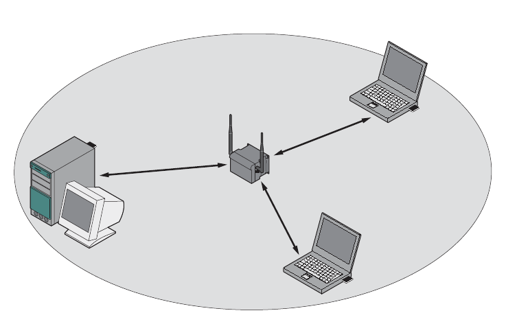
Standalone configuration with the SCALANCE W78x
This configuration does not require a server and the SCALANCE W78x does not have a
connection to a wired Ethernet. Within its transmission range, the SCALANCE W78x
forwards data from one WLAN node to another.
The wireless network has a unique name. All the devices exchanging data within this
network must be configured with this name.
Figure 2-1 Standalone configuration of a SCALANCE W78x. The gray area indicates the wireless
transmission range of the SCALANCE W78x.
Description
2.1 Network structures
SCALANCE W786-xPRO
14 Operating Instructions, Release 08/2007, C79000-G8976-C221-02
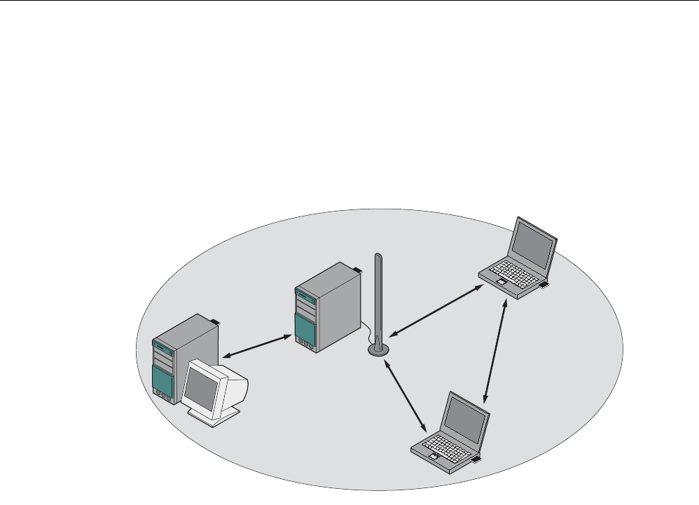
Ad hoc networks
In ad hoc mode, nodes communicate with each other directly (connection 4) without
involving a SCALANCE W78x. The nodes access common resources (files or even devices,
for example printers) of the server (connections 1 to 3 in the figure). This is, of course, only
possible when the nodes are within the wireless range of the server or within each other's
range.
1
2
3
4
Figure 2-2 Ad hoc network without SCALANCE W78x
Description
2.1 Network structures
SCALANCE W786-xPRO
Operating Instructions, Release 08/2007, C79000-G8976-C221-02 15
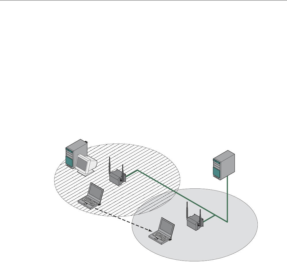
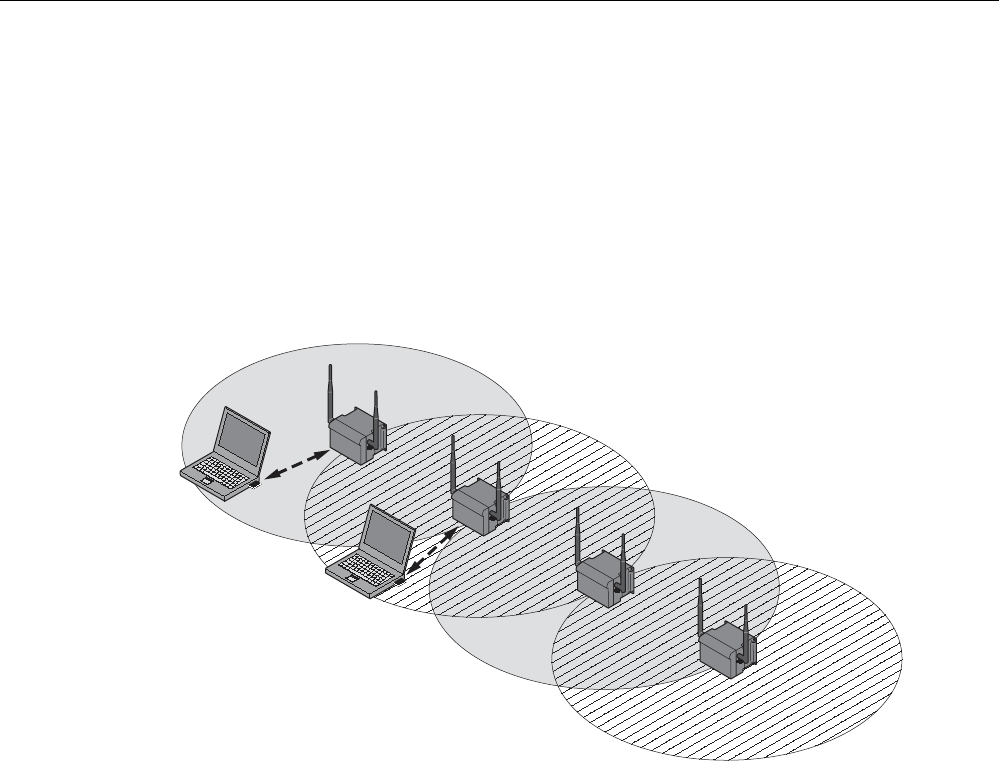
Wireless access to a wired Ethernet network
If one (or more) SCALANCE W78x access points have access to wired Ethernet, the
following applications are possible:
● A single SCALANCE W78x as gateway:
A wireless network can be connected with a wired network over a SCALANCE W78x.
● Span of wireless coverage for the wireless network with several SCALANCE W78x
access points:
The SCALANCE W78x access points are all configured with the same unique SSID
(network name). All nodes that want to communicate over this network must also be
configured with this SSID.
If a mobile station moves from the coverage range (cell) of one SCALANCE W78x to the
coverage range (cell) of another SCALANCE W78x, the wireless connection is
maintained (this is called roaming).
Figure 2-3 Wireless connection of a mobile station over two cells (roaming)
Description
2.1 Network structures
SCALANCE W786-xPRO
16 Operating Instructions, Release 08/2007, C79000-G8976-C221-02
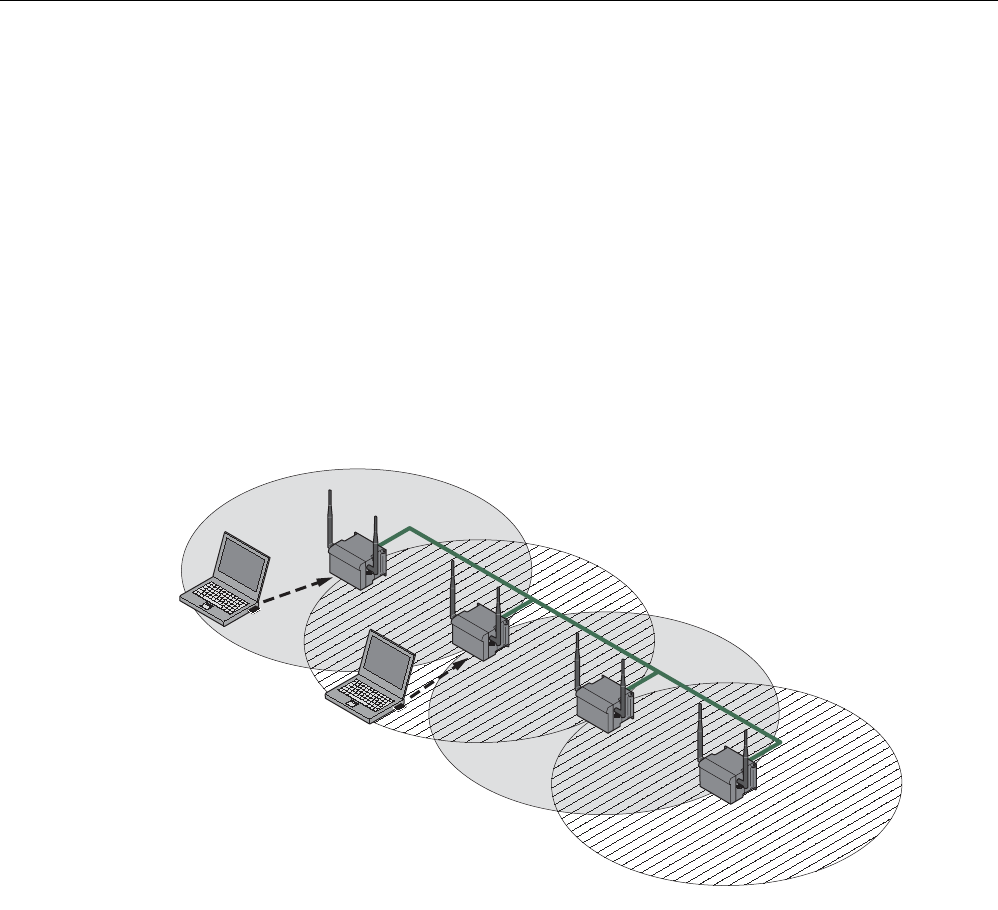
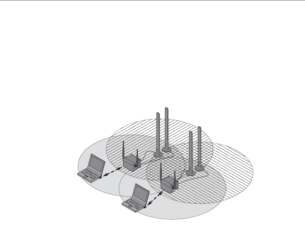
Multichannel configuration
If neighboring SCALANCE W78x access points use the same frequency channel, the
response times are longer due to the collisions that occur. If the configuration shown in the
figure is implemented as a single-channel system, computers A and B cannot communicate
at the same time with the SCALANCE W78x access points in their cells.
If neighboring SCALANCE W78x access points are set up for different frequencies, this
leads to a considerable improvement in performance. As a result, neighboring cells each
have their own medium available and the delays resulting from time-offset transmission no
longer occur.
Channel spacing should be as large as possible; a practical value would be 25 MHz (five
channels). Even in a multichannel configuration, all SCALANCE W78x access points can be
configured with the same network name.
1
1
2
2
A
B
Figure 2-4 Multichannel configuration on channels 1 and 7 with four SCALANCE W78x access
points
Description
2.1 Network structures
SCALANCE W786-xPRO
Operating Instructions, Release 08/2007, C79000-G8976-C221-02 17
Wireless Distribution System (WDS)
WDS allows direct connections between SCALANCE W78x devices and or between
SCALANCE W78x and other WDS-compliant devices. These are used to create a wireless
backbone or to connect an individual SCALANCE W78x to a network that cannot be
connected directly to the cable infrastructure due to its location.
Two alternative configurations are possible. The WDS partner can be configured both using
its name and its MAC address.
1
1
1
1
A
B
Figure 2-5 Implementation of WDS with four SCALANCE W78x access points
Description
2.1 Network structures
SCALANCE W786-xPRO
18 Operating Instructions, Release 08/2007, C79000-G8976-C221-02
Redundant Wireless LAN (RWLAN)
RWLAN allows a redundant, wireless connection between two SCALANCE W78x devices
with at least two WLAN interfaces. This is used to set up a redundant wireless backbone that
cannot be implemented as a wired network due to its location but nevertheless has high
demands in terms of availability.
Two alternative configurations are possible. The RWLAN partner can be configured both
using its name and its MAC address.
A
B
Figure 2-6 Implementing RWLAN with two SCALANCE W78x devices with at least two WLAN
interfaces. As an alternative, data transfer is possible over one of the two wireless
adapters.

Description
2.2 Scope of delivery
SCALANCE W786-xPRO
Operating Instructions, Release 08/2007, C79000-G8976-C221-02 19
2.2 Scope of delivery
The following components are supplied with the SCALANCE W786:
● SCALANCE W786
● 5 caps for the cover screws
● Depending on the version, up to 8 plugs for sealing the housing.
● Depending on the version, up to 8 strain relief clamps
● 1 connector for the 48 V DC power supply
● 2 adhesive sealing foils for oval fiber-optic cables
(not for devices with RJ-45 port)
● 1 SIMATIC NET Industrial Wireless LAN CD with these Operating Instructions for the
SCALANCE W78x
● 1 Operating Instructions (compact) SCALANCE W786
Please check that the consignment you have received is complete. If it is not complete,
please contact your supplier or your local Siemens office.

Description
2.3 Product properties
SCALANCE W786-xPRO
20 Operating Instructions, Release 08/2007, C79000-G8976-C221-02
2.3 Product properties
Possible applications of the SCALANCE W786
The SCALANCE W786 is equipped with an Ethernet port and up to three wireless LAN ports.
This makes the device suitable for the following applications:
● The SCALANCE W786 forwards data within its transmission range from one node to
another without a connection to wired Ethernet being necessary.
● The SCALANCE W786 can be used as a gateway from a wired to a wireless network.
● The SCALANCE W786 can be used as a wireless bridge between two networks.
● The SCALANCE W786 can be used as a bridge between two cells operating at different
frequencies.
With a SCALANCE W786 with more than one WLAN port, you can also implement a
redundant wireless connection to a SCALANCE W78x with at least two WLAN ports.
Properties of the SCALANCE W786
● The Ethernet interface supports 10 Mbps and 100 Mbps, both in full and half duplex as
well as autocrossing and autopolarity.
● Operating the wireless interface in the frequency bands 2.4 GHz and 5 GHz.
● The wireless interface is compatible with the standards IEEE 802.11a, IEEE 802.11h,
IEEE 802.11b and IEEE 802.11g. In the 802.11a, 802.11h and 802.11g mode, the gross
transmission rate is up to 54 Mbps. In turbo mode, the transmission rate is up to 108
Mbps (not permitted in all countries and modes).
● As an expansion of the 802.11a mode, it is also possible to operated according to the
IEEE 802.11h standard. In 802.11h mode, the procedures Transmit Power Control (TPC)
and Dynamic Frequency Selection (DFS) are used in the range 5.25 - 5.35 and 5.47 -
5.75 GHz. In some countries, this allows the frequency subband of 5.47 - 5.725 GHz to
be used outdoors even with a higher transmit power.
TPC is a technique of controlling the transmit power by reducing it to the strength actually
required. With dynamic frequency selection (DFS), the access point searches for primary
users (for example radar) on a randomly selected channel before starting communication.
If signals are found on the channel, this channel is disabled for 30 minutes and the
availability check is repeated on another channel.
● Support of the authentication standards WPA, WPA-PSK, WPA2, WPA2-PSK and
IEEE 802.1x and the encryption methods WEP, AES and TKIP.
● Suitable for inclusion of a RADIUS server for authentication.
● Device-related and application-related monitoring of the wireless connection.
● The interoperability of the devices with Wi-Fi devices of other vendors was tested
thoroughly.
Note
In client mode, you can use a SCALANCE W786-xPRO with the functionality of a
SCALANCE W746-1PRO.

Description
2.3 Product properties
SCALANCE W786-xPRO
Operating Instructions, Release 08/2007, C79000-G8976-C221-02 21
The following table illustrates the differences between the various variants of the
SCALANCE W786:
Type Number of
WLAN ports
Number and
type of
Ethernet ports
Number of
internal
antennas
Number of R-
SMA sockets
for external
antennas
Order no.
W786-1PRO 1 1 RJ-45 1
(diversity(2))
— 6GK5786-
1BA60-2AA0
6GK5786-
1BA60-2AB0
(1)
W786-1PRO 1 1 RJ-45 — 2 6GK5786-
1AA60-2AA0
6GK5786-
1AA60-2AB0
(1)
W786-1PRO 1 1 ST duplex
multimode FO
cable
1
(diversity(2))
— 6GK5786-
1BB60-2AA0
6GK5786-
1BB60-2AB0
(1)
W786-1PRO 1 1 ST duplex
multimode FO
cable
— 2 6GK5786-
1AB60-2AA0
6GK5786-
1AB60-2AB0
(1)
W786-2PRO 2 1 RJ-45 2
(diversity(2))
— 6GK5786-
2BA60-2AA0
6GK5786-
2BA60-2AB0
(1)
W786-2PRO 2 1 RJ-45 — 4 6GK5786-
2AA60-2AA0
6GK5786-
2AA60-2AB0
(1)
W786-2PRO 2 1 ST duplex
multimode FO
cable
2
(diversity(2))
— 6GK5786-
2BB60-2AA0
6GK5786-
2BB60-2AB0
(1)
W786-2PRO 2 1 ST duplex
multimode FO
cable
— 4 6GK5786-
2AB60-2AA0
6GK5786-
2AB60-2AB0
(1)

Description
2.3 Product properties
SCALANCE W786-xPRO
22 Operating Instructions, Release 08/2007, C79000-G8976-C221-02
Type Number of
WLAN ports
Number and
type of
Ethernet ports
Number of
internal
antennas
Number of R-
SMA sockets
for external
antennas
Order no.
W786-3PRO 3 1 RJ-45 — 6 6GK5786-
3AA60-2AA0
6GK5786-
3AA60-2AB0
(1)
W786-3PRO 3 1 ST duplex
multimode FO
cable
— 6 6GK5786-
3AB60-2AA0
6GK5786-
3AB60-2AB0
(1)
(1) US variant
(2) There are two internal antennas per WLAN port. The antenna used is always the one that
provides the best possible data transmission (diversity).
Requirements for installation and operation
A PG/PC with a network attachment must be available to configure the SCALANCE W786. If
no DHCP server is available, a PC on which the Primary Setup Tool (PST) is installed is
necessary for the initial assignment of an IP address to the SCALANCE W786. For the other
configuration settings, a computer with Telnet or an Internet browser is necessary.
Description
2.4 LED display
SCALANCE W786-xPRO
Operating Instructions, Release 08/2007, C79000-G8976-C221-02 23
2.4 LED display
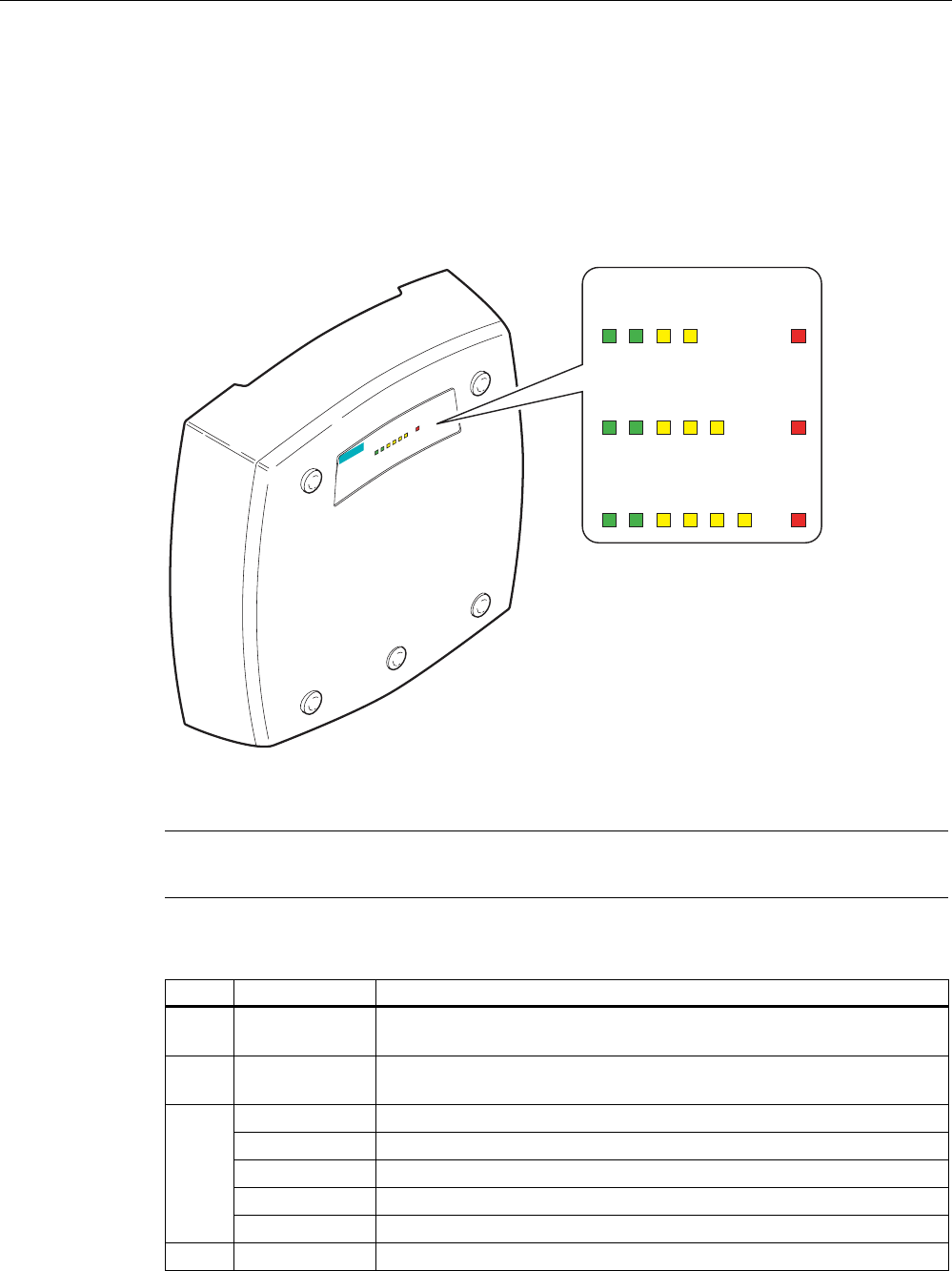
Information on operating status and data transfer
On the front of the housing, several LEDs provide information on the operating status of the
SCALANCE W786:
s
L1P1R1R2R3F
PoE
SCALANCE W786-3
L1 P1 R1 F
PoE
SCALANCE W786-1x
L1 P1 R1 R2 F
PoE
SCALANCE W786-2x
L1 P1 R1 R2 R3 F
PoE
SCALANCE W786-3x
Figure 2-7 The LED display of the SCALANCE W786
Note
The "PoE" LED does not exist on devices with a port for FO cable.
LED Color Description
L1 Green Power supply over a power supply adapter or the 48 V DC energy
contacts of devices with a port for FO cable.
PoE Green Power over Ethernet or power over the 48 V DC energy contacts of
devices with an RJ-45 port.
Yellow Data transfer over the Ethernet interface (traffic).
Green There is a connection over the Ethernet port. (Link).
Flashing yellow PRESET-PLUG detected.
Yellow/green PRESET function completed successfully.
P1
Flashing green "Flashing" enabled over PST.
R1 Yellow Data transfer over the first WLAN interface.

Description
2.4 LED display
SCALANCE W786-xPRO
24 Operating Instructions, Release 08/2007, C79000-G8976-C221-02
LED Color Description
Green
Access Point Mode:
The WLAN interface is initialized and ready for operation.
Client Mode:
There is a connection over the first WLAN port.
Flashing green
Access Point Mode:
The channels are being scanned.
Client Mode:
The client is searching for a connection to an access point or ad hoc
network.
Green flashing
quickly
Access Point Mode:
With 802.11h, the channel is scanned for one minute for primary users
before the channel can be used for data traffic.
Client Mode:
The client waits for the adopt MAC address due to the setting <Auto Find
Adopt MAC> and is connected to no access point.
Green
3x fast,
1x long flashing
Client Mode:
The client waits for the adopt MAC address due to the setting <Auto Find
Adopt MAC> and is connected to an access point.
Flashing yellow PRESET-PLUG detected.
Yellow/green PRESET function completed successfully.
Yellow
Access Point Mode:
Data transfer over the second WLAN port.
Client Mode:
The LED is always off because the 2nd port is not available in client
mode.
Green
Access Point Mode:
The WLAN interface is initialized and ready for operation.
Client Mode:
The LED is always off because the 2nd port is not available in client
mode.
Flashing green
Access Point Mode:
The channels are being scanned.
Client Mode:
The LED is always off because the 2nd port is not available in client
mode.
Green flashing
quickly
Access Point Mode:
With 802.11h, the channel is scanned for one minute for primary users
before the channel can be used for data traffic.
Client Mode:
The LED is always off because the 2nd port is not available in client
mode.
Flashing yellow PRESET-PLUG detected.
R2
Yellow/green PRESET function completed successfully.
R3 Yellow
Access Point Mode:
Data transfer over the third WLAN port.
Client Mode:
The LED is always off because the 3rd port is not available in client
mode.

Description
2.4 LED display
SCALANCE W786-xPRO
Operating Instructions, Release 08/2007, C79000-G8976-C221-02 25
LED Color Description
Green
Access Point Mode:
The WLAN interface is initialized and ready for operation.
Client Mode:
The LED is always off because the 3rd port is not available in client
mode.
Flashing green
Access Point Mode:
The channels are being scanned.
Client Mode:
The LED is always off because the 3rd port is not available in client
mode.
Green flashing
quickly
Access Point Mode:
With 802.11h, the channel is scanned for one minute for primary users
before the channel can be used for data traffic.
Client Mode:
The LED is always off because the 3rd port is not available in client
mode.
Flashing yellow PRESET-PLUG detected.
Yellow/green PRESET function completed successfully.
Red An error occurred during operation with the SCALANCE W786. F
Flashing red Ready to load firmware. The device was either stopped with the reset
button or there is incorrect firmware on the device.
Note
If the LED for the WLAN port is not green when the device starts up, although it is activated,
the port is not ready for operation (interface not initialized).
The main reason for this is usually that during commissioning of the SCALANCE W78x
products, a waiting time of up to 15 minutes can occur when the ambient temperature is
below zero. The device is ready for operation at the specified ambient temperature as soon
as the LED for the WLAN interface is lit green.

Description
2.5 C-PLUG
SCALANCE W786-xPRO
26 Operating Instructions, Release 08/2007, C79000-G8976-C221-02
2.5 C-PLUG
Configuration information on the C-PLUG
The C-PLUG is used to transfer the configuration of the old device to the new device when a
device is replaced. When the new device starts up with the C-PLUG, it then continues
automatically with exactly the same configuration as the old device. One exception to this
can be the IP configuration if it is set over DHCP and the DHCP server has not been
reconfigured accordingly.
Reconfiguration is necessary if you use WDS or redundancy with devices with more than
one WLAN interface and use the MAC addresses and not the sysNames. These functions
are then based on the MAC address that inevitably changes if a device is replaced.
Note
In terms of the C-PLUG, the SCALANCE W-700 devices work in two modes:
• Without C-PLUG
The device stores the configuration in internal memory. This mode is active when no C-
PLUG is inserted.
• With C-PLUG
The configuration stored on the C-PLUG is displayed over the user interfaces. In this
mode, the internal memory is neither read nor written. If changes are made to the
configuration, the device stores the configuration directly on the C-PLUG. This mode is
active when no C-PLUG is inserted. As soon as the device is started with a C-PLUG
inserted, the SCALANCE W-700 starts up with the configuration data on the C-PLUG.
Description
2.6 Reset button
SCALANCE W786-xPRO
Operating Instructions, Release 08/2007, C79000-G8976-C221-02 27
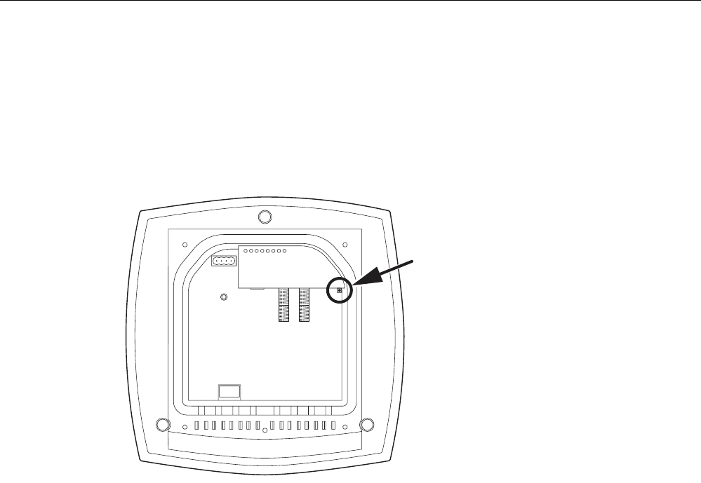
2.6 Reset button
Functions of the reset button
The reset button is located below the housing cover beside the sockets for external
antennas.
Figure 2-8 Position of the reset button with the housing cover removed
The reset button has the following functions:
● Restart of the device
To restart the device, press the reset button.
● Loading new firmware
If the normal procedure with the Load & Save menu of Web Based Management was
completed successfully, the reset button can be used to load new firmware. This situation
can occur if there was a power outage during the normal firmware update.
● Restoring the default parameters (factory defaults)
● Adopting the configuration data from the PRESET PLUG.

Description
2.7 Biological compatibility
SCALANCE W786-xPRO
28 Operating Instructions, Release 08/2007, C79000-G8976-C221-02
2.7 Biological compatibility
Electromagnetic fields and health
With regard to the question of whether electromagnetic fields (for example in association
with industrial wireless LANs) can put human health at risk, we refer to a publication of
BITKOM (German Association for information Technology, Telecommunication and New
Media e. V.), dated December 2003:
"The same health guidelines apply to WLAN devices as to all other radio applications. These
regulations are based on the protection concept of ICNIRP1 or the corresponding
recommendation of the European Council.
The independent German radiation protection commission (SSK) was commissioned by the
federal German ministry of the environment to investigate the possible dangers - thermal and
non-thermal - resulting from electromagnetic fields and came to the following conclusions2:
'The German Commission on Radiological Protection concludes that according to the latest
scientific literature no new scientific research is available with respect to proven health
hazards which would throw doubt upon the scientific evaluation which serves as the basis for
the ICNIRP safety concepts and the recommendations of the EU commission.'
The SSK also concludes that below the current limit values, these is also no scientific
suspicion of health risks.
This assessment agrees with those of other national and international scientific commissions
and of the WHO (www.who.int/emf).
Accordingly and in view of the fact that WLAN devices are significantly below the
scientifically established limit values, there are no health risks from the electromagnetic fields
of WLAN products.
1 International Council on Non-Ionizing Radiation Protection
2 'Limit Values and Precautionary Measures to Protect the General Public from
Electromagnetic Fields' Recommendation of the Radiation Protection Commission (SSK)
with scientific justification, Issue 29, 2001."
You will find further information on this topic under the following URL:
www.bitkom.org

SCALANCE W786-xPRO
Operating Instructions, Release 08/2007, C79000-G8976-C221-02 29
Assembly 3
3.1 Removing / fitting the housing cover
When does the housing cover need to be removed?
You can only perform the following activities when the cover is removed.
● You want to screw the SCALANCE W786 to a wall or onto the optional mounting plate.
● You want to connect cables to the SCALANCE W786 for the power supply, for Ethernet
or for external antennas.
● You want to insert a C-PLUG in the device or replace an existing C-PLUG.
● You want to use the reset button.
Removing the housing cover
WARNING
Danger from line voltage
After removing the housing cover, there is a risk of touching live parts.
Remove the housing cover only after you have turned off the power supply of the
SCALANCE W786.

Assembly
3.1 Removing / fitting the housing cover
SCALANCE W786-xPRO
30 Operating Instructions, Release 08/2007, C79000-G8976-C221-02
s
SCALANCE W786-3
L1 P1 R1 R2 R3 F
PoE
A
C
B
Figure 3-1 Removing the cover
A Sealing cap
B Cover screw
C Housing cover
Follow the steps below to remove the housing cover:
1. Remove the sealing caps from the housing cover (position A in the figure above)
2. Loosen the screws in the cover (position B in the figure above).
Note
These screws remain in the cover after they have been loosened (prevents them being
lost). Never attempt to remove these screws from the housing cover using force,
otherwise the housing cover will be damaged!
3. Remove the housing cover with the captive screws (position C in the figure above).
Fitting the housing cover
Fitting the housing cover is carried out in the reverse order. Tightening torque for the cover
screws 1.8 Nm.
Assembly
3.2 Connecting up cables
SCALANCE W786-xPRO
Operating Instructions, Release 08/2007, C79000-G8976-C221-02 31
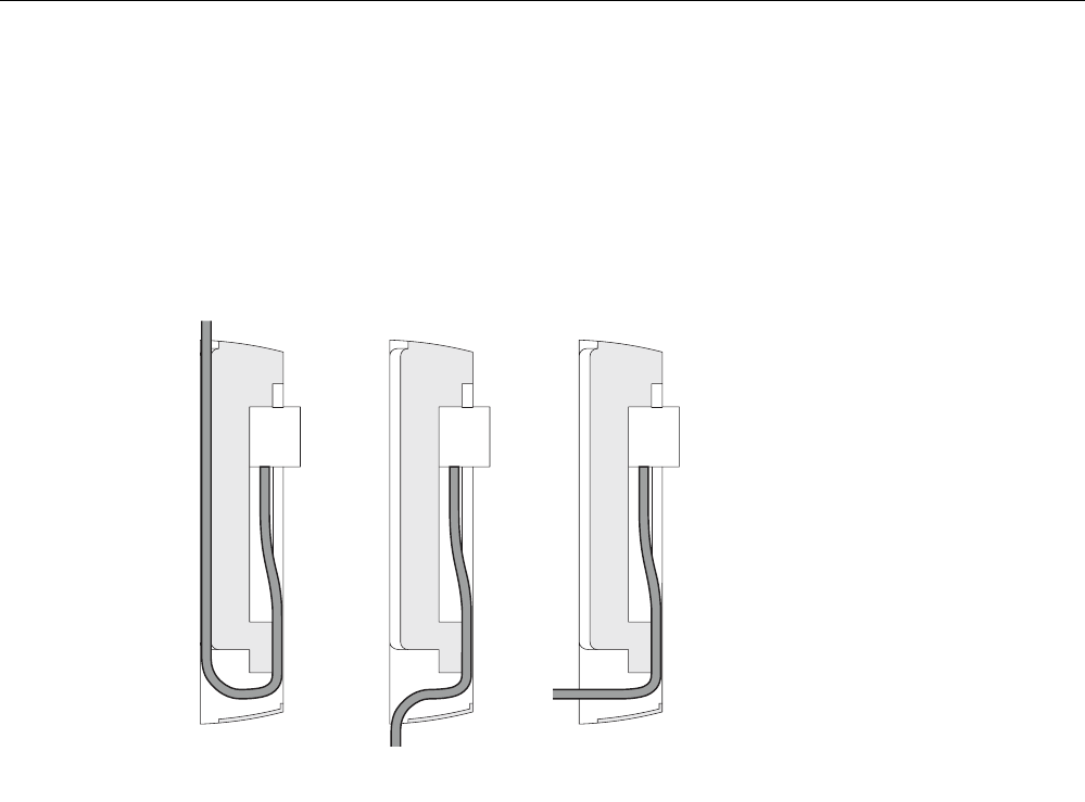
3.2 Connecting up cables
Connecting up cables prior to mounting
Before you screw a SCALANCE W786 to a wall or to the optional mounting plate, the cables
for the power supply, for Ethernet, and, when necessary, for the external antennas must be
connected up first. The available options are as follows:
AB C
Figure 3-2 Side view of a SCALANCE W786 with cables entering from different directions
● The cables are inserted from above (position A in the previous schematic). The housing
of the SCALANCE W786 has an opening at the top for this purpose.
● The cables are inserted from below (position B in the previous schematic). There is also
an opening at the bottom for this purpose.
● Cables inserted through a wall behind the SCALANCE W786 (position C in the previous
schematic). In this case, you will need to mount the SCALANCE W786 so that the
opening in the wall is located above the lower edge of the device.
Assembly
3.2 Connecting up cables
SCALANCE W786-xPRO
32 Operating Instructions, Release 08/2007, C79000-G8976-C221-02
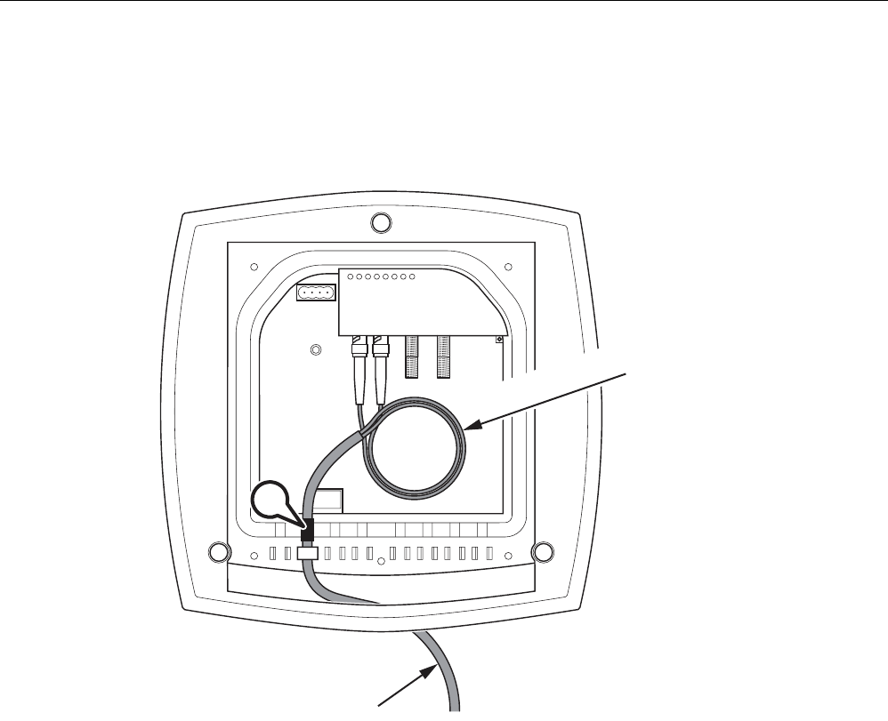
Connecting up FO cables
Fiber-optic cables have a minimum bending radius. The cable must not be bent tighter than
this bending radius during installation or operation, otherwise the FO cable will be irreperably
damaged.
R*
R > 25 mm
A
Figure 3-3 Connecting up an FO cable
For the FO cable, use the second opening from the left in the seal. Cable routing is
illustrated in the figure above. For individual cores immediately following the connector, the
minimum bending radius is 25 mm. Refer to the specification of the cable you are using for
the minimum permitted bending radius of the cable within the jacket. Make sure that the FO
cable is not sharply kinked after passing through the housing.
An adhesive sealing foil must be used in the housing sealing with FO cables (position A in
the figure above). For more detailed information, refer to the section "Connecting the
cables".
Assembly
3.2 Connecting up cables
SCALANCE W786-xPRO
Operating Instructions, Release 08/2007, C79000-G8976-C221-02 33
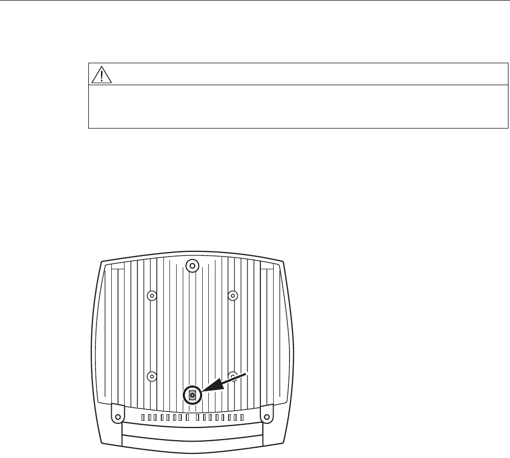
Grounding terminal
WARNING
To operate the SCALANCE W786 safely, the chassis ground connector must have a
suitable cable connected. Do not use the SCALANCE W786 without a ground cable
connected.
The chassis ground connector is located on the rear of the device (M4 thread). Connect the
ground cable before you mount the SCALANCE W786 on a wall or on the optional mounting
plate. Once the SCALANCE W786 is mounted, the connector is no longer accessible.
Place the supplied toothed washer directly on the rear of the device before screwing on the
ground cable. Only then can you be sure that there is ideal contact with the screwed-on
cable.
Figure 3-4 Chassis ground connector on the rear of the SCALANCE W786

Assembly
3.3 Mounting without an adapter (wall mounting only)
SCALANCE W786-xPRO
34 Operating Instructions, Release 08/2007, C79000-G8976-C221-02
3.3 Mounting without an adapter (wall mounting only)
Drilling template
The location of the holes for mounting the SCALANCE W786 on a wall is shown in the
following figure:
34 184
46 187 19
34
Figure 3-5 Drilling template for wall mounting of the SCALANCE W786
Assembly
3.3 Mounting without an adapter (wall mounting only)
SCALANCE W786-xPRO
Operating Instructions, Release 08/2007, C79000-G8976-C221-02 35
Procedure
A
B
Figure 3-6 SCALANCE W786 wall mounting
Follow the steps below to screw a SCALANCE W786 to a wall:
1. Lead the cables into the housing of the SCALANCE W786 (position A in the figure
above). Note the information in the section "Connecting up cables".
2. Secure the SCALANCE W786 to the wall with three screws (position B in the figure
above). The screws are not supplied with the device. The type and length of the screws
depend on the type of wall.
Type of screw:
– for wooden walls: wood screw 4 x 30 mm
– for concrete walls: 4 x 50 mm with 5 mm concrete plug
– for metal walls: M4 x 25 mm with machine thread in the wall

Assembly
3.3 Mounting without an adapter (wall mounting only)
SCALANCE W786-xPRO
36 Operating Instructions, Release 08/2007, C79000-G8976-C221-02
Option: Threaded holes on rear of housing
When a wall is extremely thin, it is often not possible to use wall plugs for the screws. To
allow wall mounting even in this situation, there are four M4 threaded holes on the rear of the
SCALANCE W786. The drilling template is a square with sides 100 mm long. The device can
therefore be mounted on a wall with bolts through the wall.
Calculate the length of the required M4 screws as follows:
Screw length = wall thickness + 7 mm
Assembly
3.4 Mounting with mounting plate
SCALANCE W786-xPRO
Operating Instructions, Release 08/2007, C79000-G8976-C221-02 37
3.4 Mounting with mounting plate
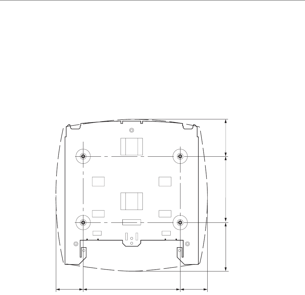
3.4.1 Fitting the mounting plate to a wall
Drilling template
The location of the holes for fitting the mounting plate to a wall is shown in the following
figure:
160
46 46
81 109 62
Figure 3-7 Drilling template for fitting the mounting plate to a wall
Procedure
Secure the mounting plate to the wall with four screws. The screws are not supplied with the
device. The type and length of the screws depend on the type of wall.
Type of screw:
● for wooden walls: wood screw 4 x 30 mm
● for concrete walls: 4 x 50 mm with 5 mm concrete plug
● for metal walls: M4 x 25 mm with machine thread in the wall
Assembly
3.4 Mounting with mounting plate
SCALANCE W786-xPRO
38 Operating Instructions, Release 08/2007, C79000-G8976-C221-02
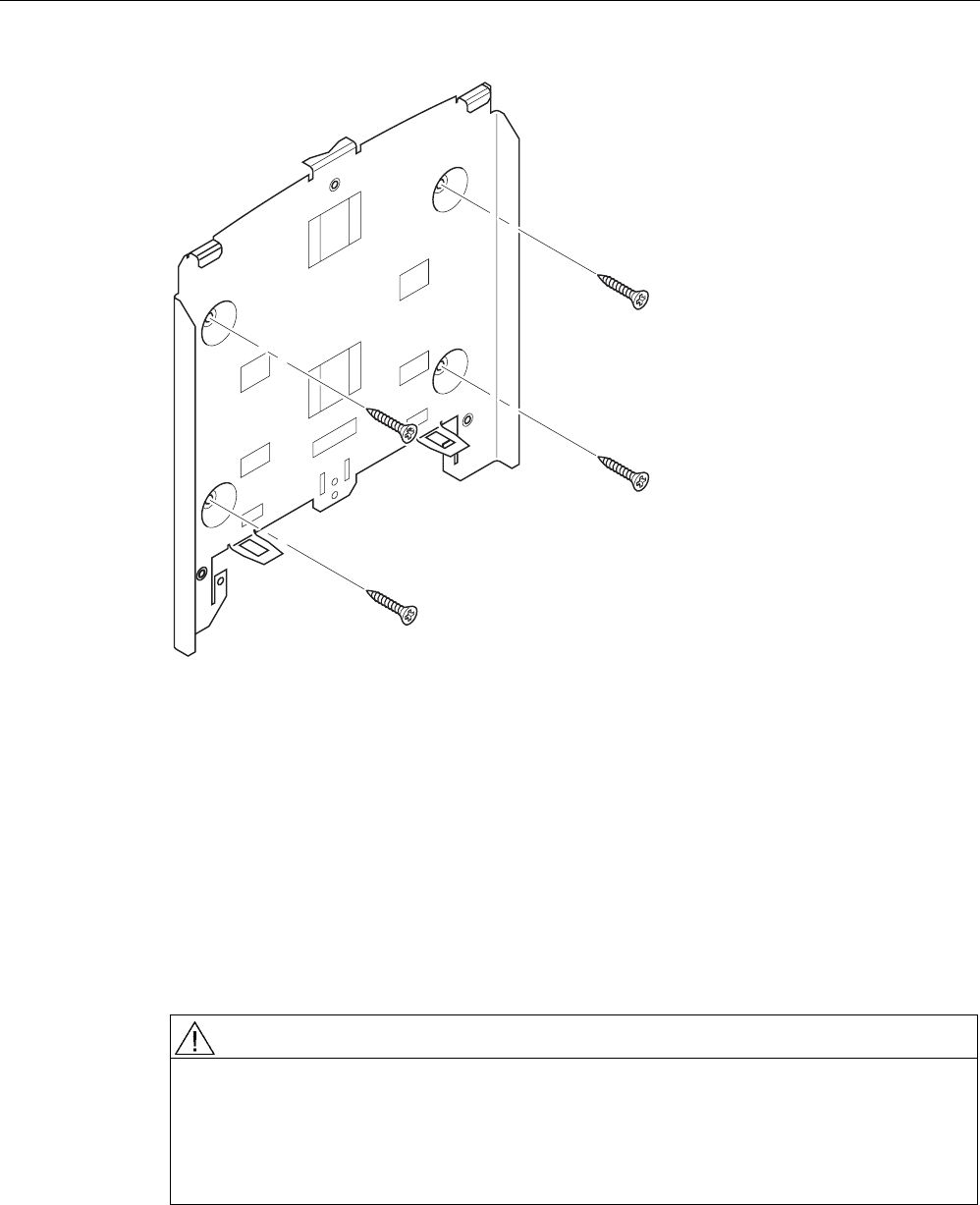
Figure 3-8 Fitting the mounting plate for the SCALANCE W786 to a wall
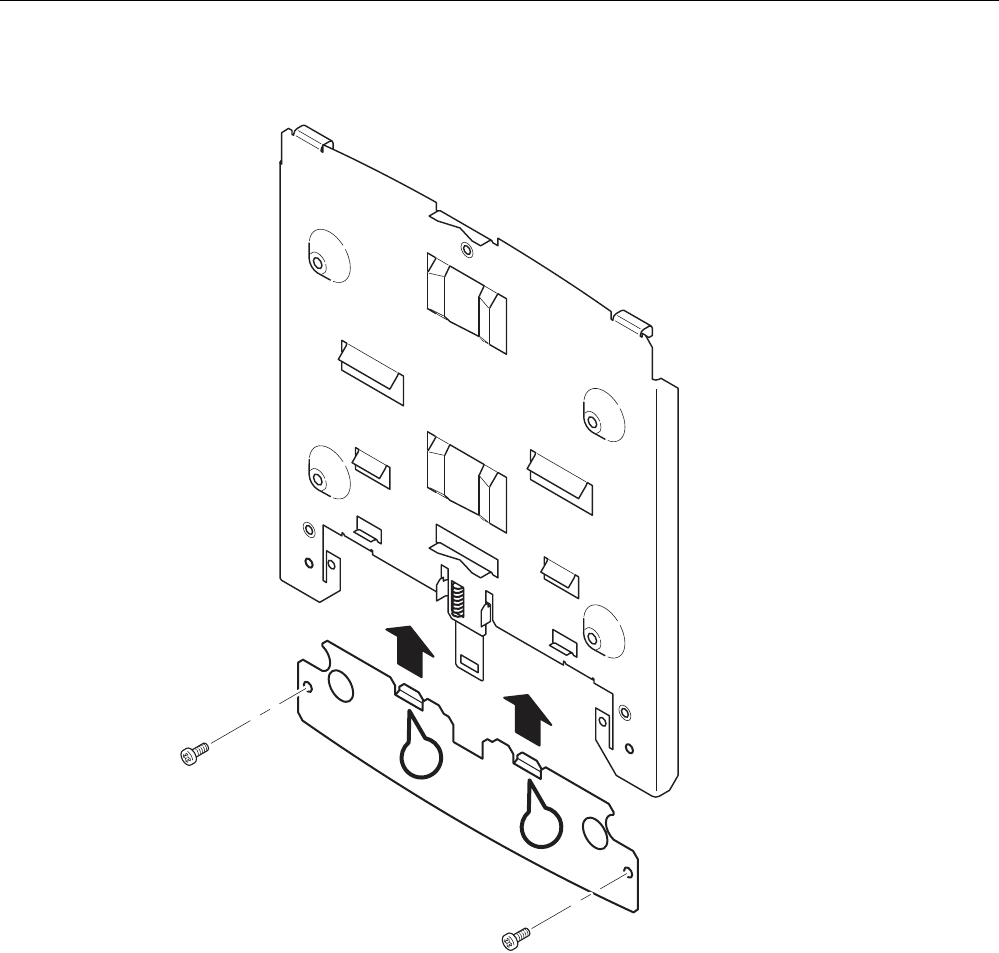
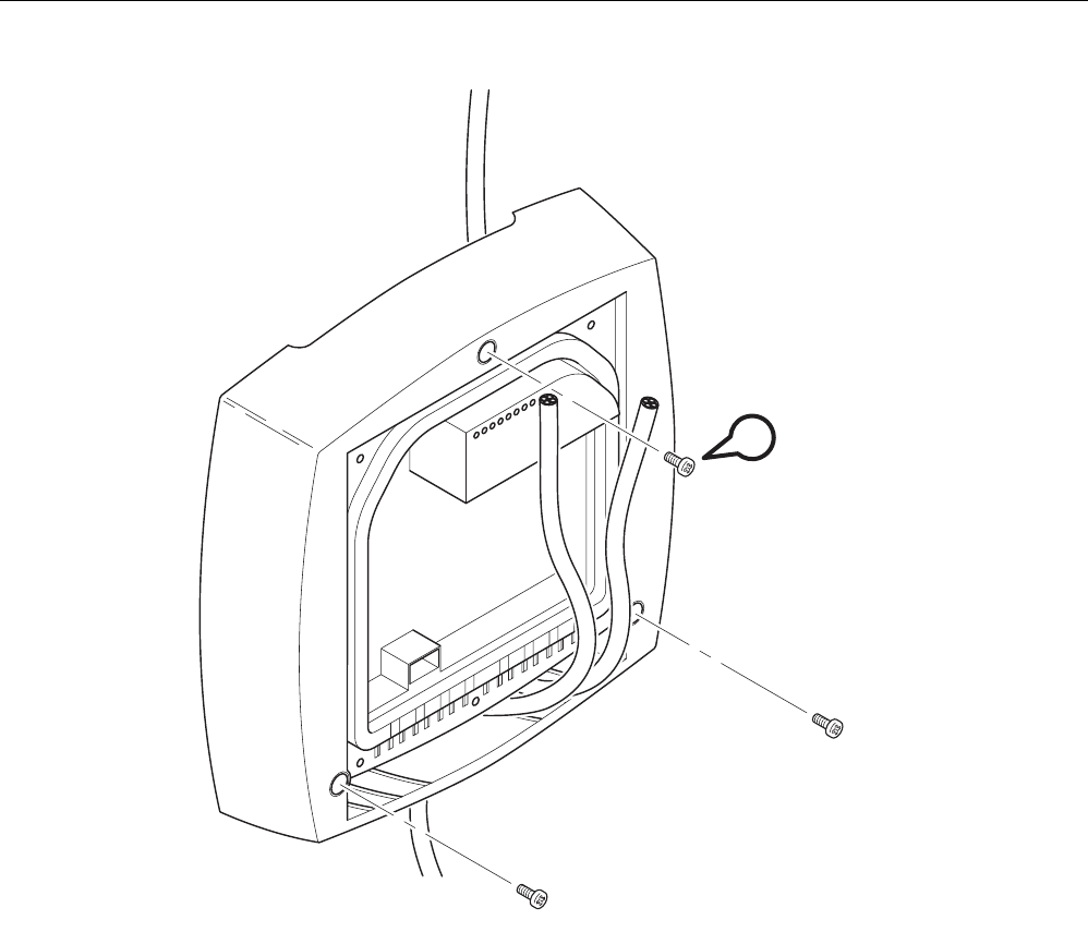
3.4.2 Screwing the cover plate for the cable feedthrough to the mounting plate
Protection of the cable feedthrough against strong water jets
The cabling of a SCALANCE W786 is led out of the rear of the device. The housing seal is
effective only when it is not subjected to water jets. If the device is mounted on a wall, this is
the case and no further measures are necessary. When mounted in any other way, except
for mounting on an S7-300 standard rail, an additional cover plate must be screwed to the
mounting plate.
WARNING
Danger from line voltage
If the cable feedthrough is subjected to strong water jets, water can penetrate the device
and create a live connection to the line voltage. There is then a risk of electric shock.
Make sure that you use the cover plate for the cable feedthrough if you do not mount the
SCALANCE W786 on a wall.
Assembly
3.4 Mounting with mounting plate
SCALANCE W786-xPRO
Operating Instructions, Release 08/2007, C79000-G8976-C221-02 39
Procedure
A
A
1
2
Figure 3-9 Fitting and securing the cover plate for the cable feedthrough
To screw the cover plate for the cable feedthrough to the mounting plate, follow the steps
below:
1. Fit the cover plate on the mounting plate from below until the two lugs (position A in the
figure above) engage the lower edge of the mounting plate.
2. Secure the cover plate to the mounting plate with two M4 screws. The screws are
supplied with the assembly kit.
Assembly
3.4 Mounting with mounting plate
SCALANCE W786-xPRO
40 Operating Instructions, Release 08/2007, C79000-G8976-C221-02
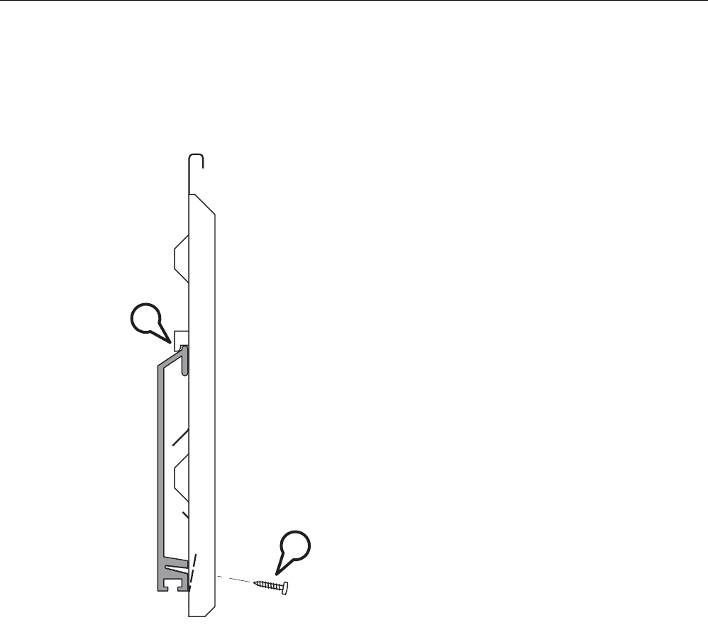
3.4.3 Fitting the mounting plate to an S7-300 standard rail
Procedure
B
A
Figure 3-10 Side view of a mounting plate on an S7-300 standard rail
Follow the steps below to fit the mounting plate to an S7-300 standard rail:
1. Place the mounting plate with the two protruding catches on the top edge of the S7-300
standard rail (position A in the figure above).
2. At the bottom, the mounting plate has two lugs with holes. Screw the lugs to the S7-300
standard rail (position B in the figure above). The required screws are supplied with the
mounting plate.
Assembly
3.4 Mounting with mounting plate
SCALANCE W786-xPRO
Operating Instructions, Release 08/2007, C79000-G8976-C221-02 41
3.4.4 Fitting the mounting plate to a DIN rail
Procedure
A
A
B
Figure 3-11 Mounting plate with fittings for DIN rail mounting
Follow the steps below to fit the mounting plate to a DIN rail:
1. Place the mounting plate with the two catches (position A in the figure above) on the
upper edge of the DIN rail.
2. Pull down the DIN rail sliding catch (position B in the figure above) and press the
mounting plate against the DIN rail until the sliding catch engages.
Assembly
3.4 Mounting with mounting plate
SCALANCE W786-xPRO
42 Operating Instructions, Release 08/2007, C79000-G8976-C221-02
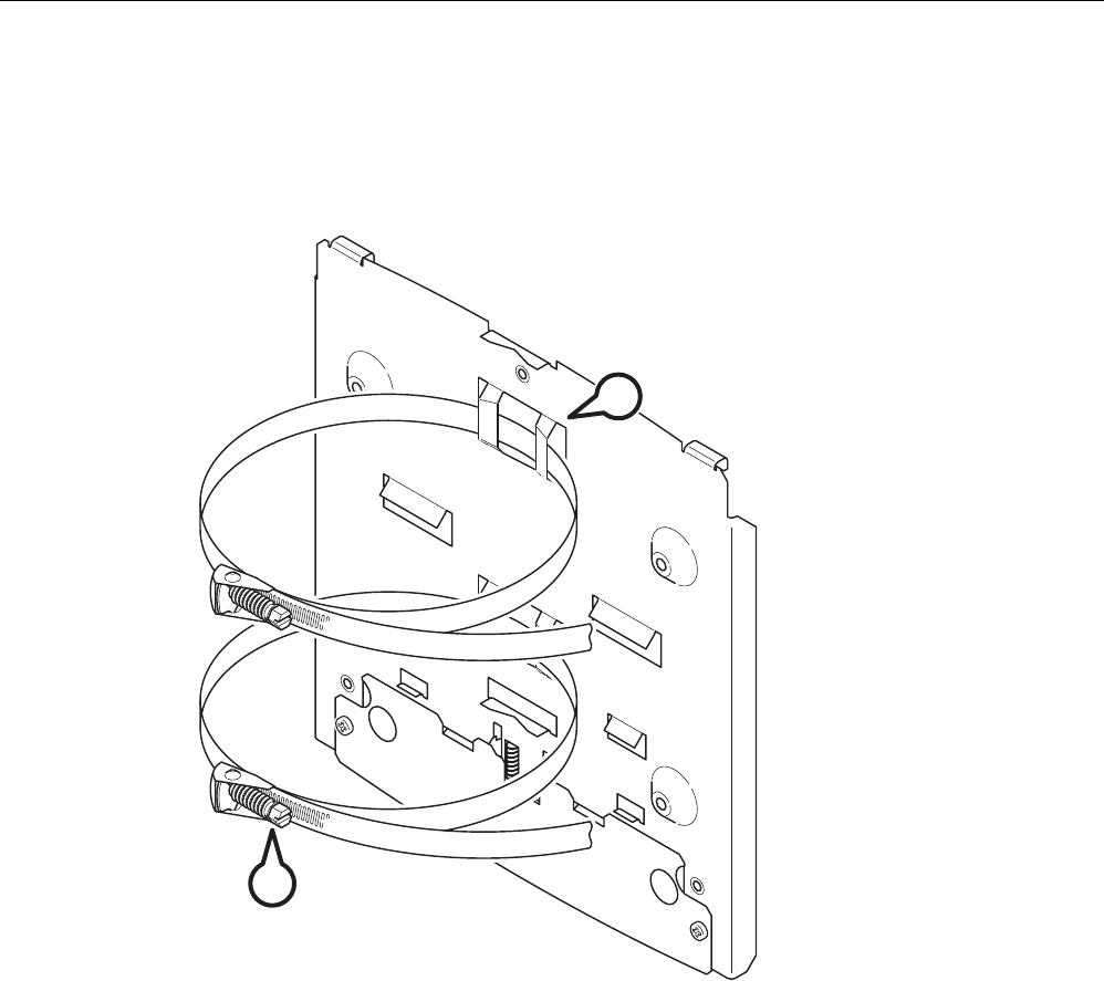
3.4.5 Fitting the mounting plate to a mast
Procedure
B
A
Figure 3-12 Mounting plate with fittings for mast mounting
Follow the steps below to fit the mounting plate to a mast:
1. Feed the fastening straps through the openings in the mounting plate (position A in the
figure above).
2. Place the fastening straps around the mast at the required position.
3. Feed the free end of the strap through the quick-release fastener. You can twist the
tensioning screw (position B in the figure above) to the side to adapt a fastening strap to
the diameter of the mast.
4. Press the tensioning screw against the fastening strap and tighten the tensioning screw,
tightening torque 4.5 Nm.

Assembly
3.4 Mounting with mounting plate
SCALANCE W786-xPRO
Operating Instructions, Release 08/2007, C79000-G8976-C221-02 43
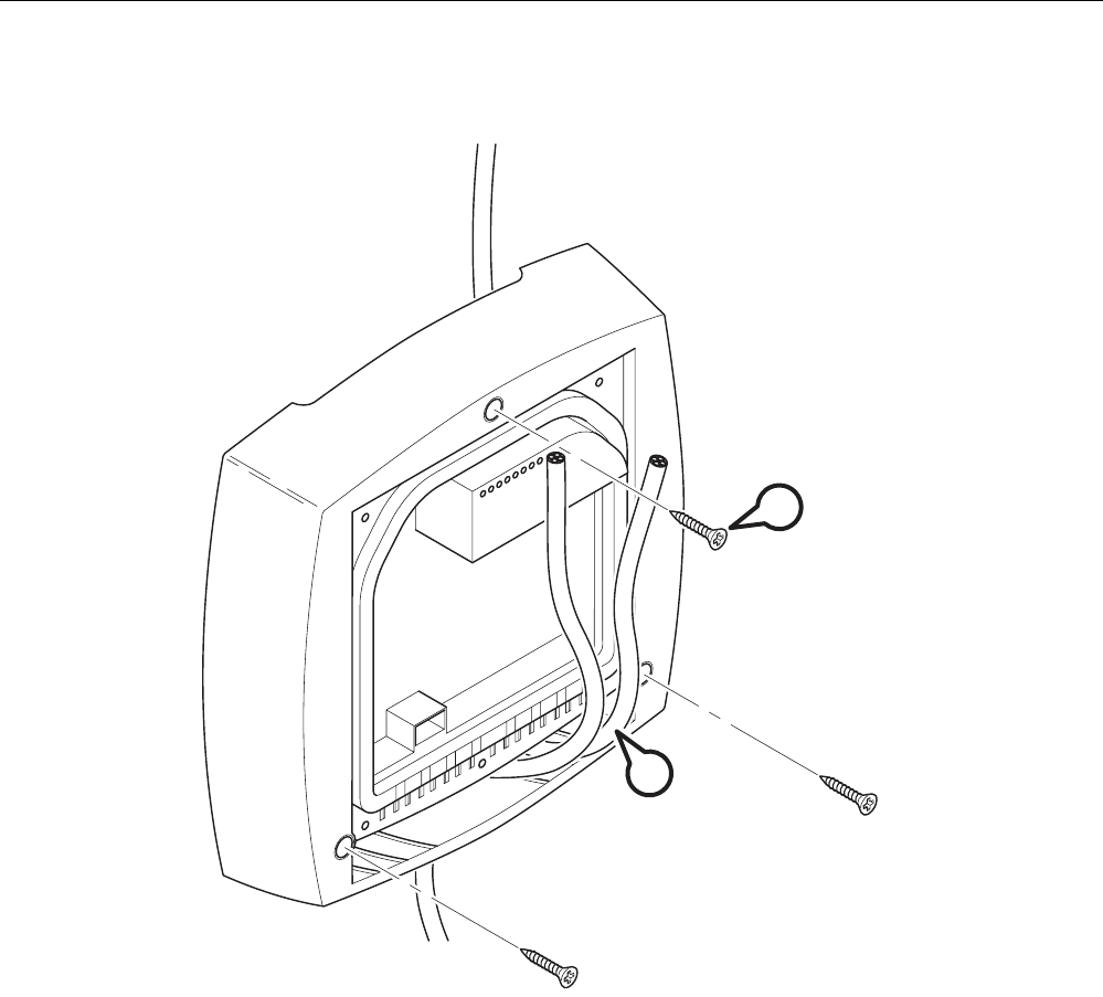
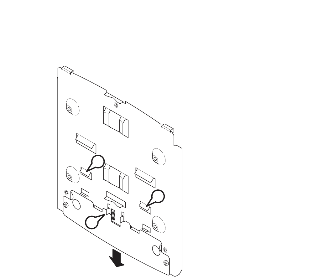
3.4.6 Fitting/removing the SCALANCE W786 to/from a mounting plate
Procedure for mounting the device
1
2
CA
B
Figure 3-13 Fitting the SCALANCE W786 to a mounting plate
Follow the steps below to fit a SCALANCE W786 to a mounting plate:
1. Lead the cables into the housing of the SCALANCE W786 (position A in the figure
above). Note the information in the section "Connecting up cables".
2. Fit the SCALANCE W786 so that the upper edge of the rear of the housing is below the
two catches of the mounting plate (position B in the figure above).
3. Push in the SCALANCE W786 until it engages in the notches at the lower edge of the
mounting plate (position C in the figure above).
Assembly
3.4 Mounting with mounting plate
SCALANCE W786-xPRO
44 Operating Instructions, Release 08/2007, C79000-G8976-C221-02
C
Figure 3-14 Screwing a SCALANCE W786 to a mounting plate
4. Screw the SCALANCE W786 using the three M4 screws supplied with the mounting plate
(position D in the figure above), tightening torque 1.8 Nm.
Procedure for removing the device
Follow the steps below to remove a SCALANCE W786 from a mounting plate:
1. Loosen the screws between the SCALANCE W786 and mounting plate.
2. Using a screwdriver or similar tool, press down the two lugs on the lower edge of the
mounting plate (position C in the first figure in this section) and release the SCALANCE
W786 from the recesses.
3. Pull out the lower edge of the SCALANCE W786 to the front and then release it from the
two clips on the mounting plate (position B in the first figure in this section).

SCALANCE W786-xPRO
Operating Instructions, Release 08/2007, C79000-G8976-C221-02 45
Connecting up 4
4.1 Lightning protection, power supply, and grounding
Notes on lightning protection
WARNING
Danger due to lightning strikes
Antennas installed outdoors must be within the area covered by a lightning protection
system. Make sure that all conducting systems entering from outdoors can be protected by
a lightning protection potential equalization system.
When implementing your lightning protection concept, make sure you adhere to the VDE
0182 or IEC 62305 standard.
A suitable lightning conductor is available in the range of accessories of SIMATIC NET
Industrial WLAN:
Lightning protector LP798-1N (order no. 6GK5798-2LP00-2AA6)
WARNING
Danger due to lightning strikes
Installing this lightning protector between an antenna and a SCALANCE W-700 is not
adequate protection against a lightning strike. The LP798-1N lightening protector only
works within the framework of a comprehensive lightning protection concept. If you have
questions, ask a qualified specialist company.
Note
The requirements of EN61000-4-5, surge immunity tests on power supply lines, are met only
when a Blitzductor is used with 12 - 24 V DC and 48 V DC:
12 - 24 V DC: VT AD 24V type no. 918 402
48 V DC: Type no. 919 545 and 919 506 (holder)
Manufacturer: DEHN+SÖHNE GmbH+Co.KG, Hans Dehn Str. 1, Postfach 1640, D-92306
Neumarkt, Germany

Connecting up
4.1 Lightning protection, power supply, and grounding
SCALANCE W786-xPRO
46 Operating Instructions, Release 08/2007, C79000-G8976-C221-02
Safety extra low voltage
WARNING
Danger to life from overvoltage, fire hazard
SCALANCE W-700 devices are designed for operation with a directly connectable safety
extra-low voltage or with the power supply adapters available as accessories (available
only for the SCALANCE W786-xPRO device). Therefore only safety extra-low voltage
(SELV) with limited power source (LPS) complying with IEC950/EN60950/VDE0805 may
be connected to the power supply terminals (exception: Power supply adapter for 110 - 230
V AC for the SCALANCE W786-xPRO).
The power supply unit to supply the SCALANCE W-700 must comply with NEC Class 2
(requirements of class 2 for power supply units of the "National Electrical Code, table 11
(b)") or SELV with LPS (Limited Power Source) EN 60950-1. If the power supply is
designed redundantly (two separate power supplies), both power supplies must meet these
requirements.
Exceptions:
• Power supply with PELV (according to VDE 0100-410 or IEC 60364-4-41) is also
possible if the generated rated voltage does not exceed the voltage limits 25 V AC or 60
V DC.
Earthing
CAUTION
Damage to the device due to potential differences
To avoid the influence of electromagnetic interference, the device should be grounded.
There must be no potential difference between the following parts, otherwise the device or
other connected device could be severely damaged:
• Housing of the SCALANCE W-700 and the ground potential of the antenna.
• Housing of the SCALANCE W-700 and the ground potential of a device connected over
Ethernet.
• Housing of the SCALANCE W-700 and the shield contact of the connected Ethernet
cable.
Connect both grounds to the same foundation earth or use an equipotential bonding cable.
Interruption of the power supply
CAUTION
Damage to the Ethernet interface
Repeated fast removal and insertion of the Ethernet cable when using Power-over-Ethernet
and when there is a redundant power supply can cause damage to the Ethernet interface.
Avoid repeatedly removing and inserting the Ethernet cable when using Power-over-
Ethernet and a redundant power supply.

Connecting up
4.2 Suitable cables and antennas for the SCALANCE W786
SCALANCE W786-xPRO
Operating Instructions, Release 08/2007, C79000-G8976-C221-02 47
4.2 Suitable cables and antennas for the SCALANCE W786
Cable specification
The following table lists the requirements for a cable depending on the use case.
Application Specification
Direct 48 V DC supply • Round cable cross-section with 6 to 8 mm
diameter.
• Permitted tensile load at least 100 N.
• UL listing: Type PLTC or ITC
Power supply adapter 12 - 24 V DC • Round cable cross-section with 6 to 8 mm
diameter.
• Permitted tensile load at least 100 N.
• UL listing: Type PLTC or ITC
Power supply adapter 110 - 230 V AC • Round cable cross-section with 6 to 8 mm
diameter.
• Three-core cable with 0.5 - 1.5 mm2 cross
section of the individual cores.
• Permitted tensile load at least 100 N.
Ethernet IE FC TP Standard Cable GP 2 x 2 (type A)
Order no. 6XV1 840-2AH10
IE TP Torsion Cable 2 x 2 (type C)
Order no. 6XV1 870-2F
IE FC TP Trailing Cable 2 x 2 (type C)
Order no. 6XV1 840 3AH10
UL listing: Type PLTC or ITC (the three named
types have this approval)
Multimode FO cable FO Standard Cable GP
Order no. 6XV1 873-2A
Minimum bending radius 65 mm.
You will find detailed information on
preassembled cable lengths and connectors in
the catalog "IK PI".
Antenna connector: N-Connect/R-SMA connecting cable
The N-Connect/R-SMA male/male flexible connecting cable is available as an accessory for
direct connection of an antenna to a SCALANCE W-700.
Length in m Order number
1
2
5
10
6XV1875-5CH10
6XV1875-5CH20
6XV1875-5CH50
6XV1875-5CN10

Connecting up
4.2 Suitable cables and antennas for the SCALANCE W786
SCALANCE W786-xPRO
48 Operating Instructions, Release 08/2007, C79000-G8976-C221-02
Antenna connector: N-Connect/ N-Connect connecting cable
The N-Connect/N-Connect male/male flexible connecting cable is available as an accessory
for connecting an antenna to the lightning protector LP798-1N.
Length in m Order number
1
2
5
10
6XV1875-5CH10
6XV1875-5CH20
6XV1875-5CH50
6XV1875-5CN10
There is a control cabinet feedthrough available for IWLAN devices located in a control
cabinet. You will find detailed information in the catalog IK PI.
Antennas
The following antennas have been approved for use with a SCALANCE W786-xPRO:
Type Properties Order no.
ANT795-6MN Omni antenna 2.4 / 5 GHz,
ceiling mounted
6GK5795-6MN00-0AA6
ANT792-6MN Omni antenna 2.4 GHz,
wall mounted
6GK5792-6MN00-0AA6
ANT793-6MN Omni antenna 5 GHz,
wall mounted
6GK5793-6MN00-0AA6
ANT792-8DN Directional antenna 2.4 GHz,
wall mounted
6GK5792-8DN00-0AA6
ANT793-8DN Directional antenna 5 GHz,
wall mounted
6GK5793-8DN00-0AA6
ANT795-6DN Directional antenna 2.4 / 5 GHz,
wall mounted
6GK5795-6DN00-0AA6
ANT792-4DN RCoax antenna 2.4 GHz 6GK5792-4DN00-0AA6
ANT793-4MN RCoax antenna 5 GHz 6GK5793-4MN00-0AA6

Connecting up
4.3 Connecting the cables
SCALANCE W786-xPRO
Operating Instructions, Release 08/2007, C79000-G8976-C221-02 49
4.3 Connecting the cables
Procedure
WARNING
Danger from line voltage
If the housing is not perfectly sealed, there is a danger to life due to the line voltage if the
SCALANCE W786 is subjected to spray water or dampness. Make sure that you keep to
the following safety rules.
• Before connecting up, turn of the power supply.
• The sealing of the cable feedthroughs of the SCALANCE W786 is only assured when
the cable has a suitable diameter and adequate tensile strength. Only use cables that
meet the specifications in the section "Cables for the SCALANCE W786". When
connecting up a FO cable, make sure that you use the adhesive sealing foil supplied
with the SCALANCE W786.
• Never wrap insulating tape, adhesive tape or other materials around thinner cables to
achieve the required diameter. In this case, neither the housing seal nor the strain relief
clamps can fulfill their function.
• Close all unused openings in the housing seal with the sealing plugs supplied with the
SCALANCE W786. Do not use fillers or any other material under any circumstances.
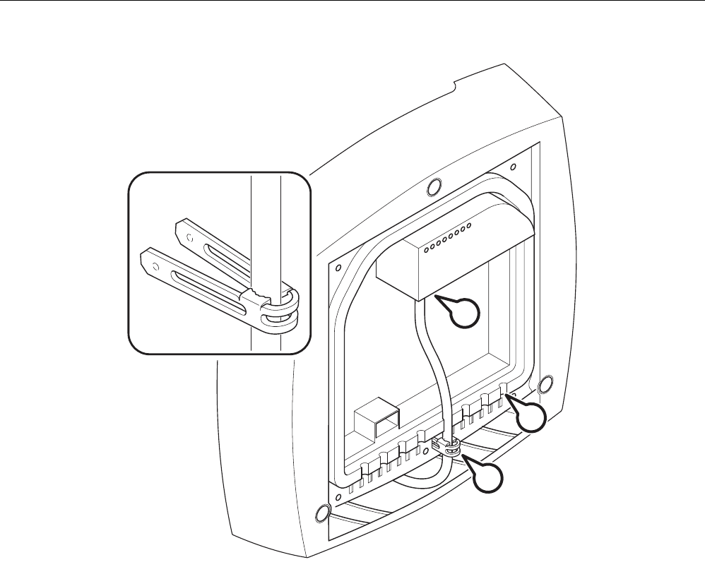
Connecting up
4.3 Connecting the cables
SCALANCE W786-xPRO
50 Operating Instructions, Release 08/2007, C79000-G8976-C221-02
C
D
A
B
Figure 4-1 Connecting a cable and fitting the strain relief clamps
Follow the steps below to connect cables to the SCALANCE W786.
1. Connect the cables to the appropriate contacts. (Position A in the figure above) You have
the following options:
– Connect cables preassembled with a connector (Ethernet, antennas) by inserting the
connector into the appropriate socket. Secure antenna cables by tightening the sleeve
nut of the connector (key size SW8). You will find more information on this topic in the
sections "Connection for Industrial Ethernet" and "Connections for external antennas".
– 48 V DC power supply. Use the connector supplied with the SCALANCE W786. For
details of the terminal assignment, refer to the section "Connectors for the power
supply".
– 12 - 24 V DC or 110 - 230 V AC power supply. With these power supplies, you require
a power supply adapter (do not ship with the SCALANCE W786). You will find more
information in the section "Connecting a power supply adapter".
2. Fit a strain relief clamp to the connected cable. The toothed part of the clamp must
enclose the cable completely (as shown by position B in the figure above).
3. Press the strain relief clamp into the housing until the cable is located completely in the
opening in the housing seal (position C in the figure above).
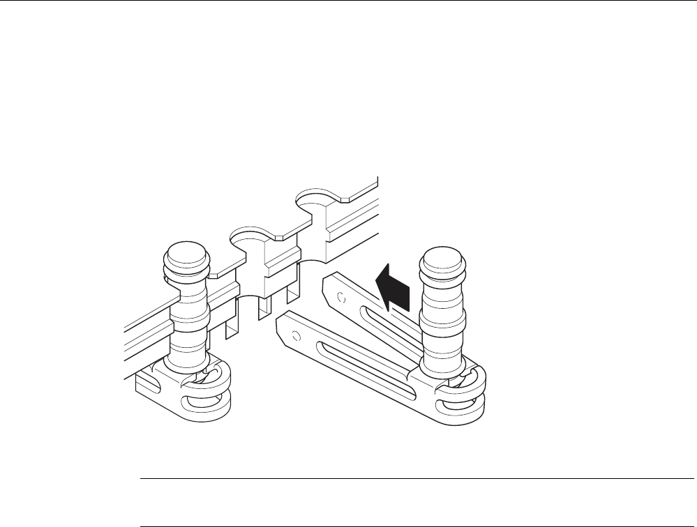
Connecting up
4.3 Connecting the cables
SCALANCE W786-xPRO
Operating Instructions, Release 08/2007, C79000-G8976-C221-02 51
4. Seal all openings not required for cables with sealing plugs (position D in the figure
above).
5. Fit these sealing plugs in a strain relief clamp. The lower surrounding notch must be
enclosed by the toothing of the strain relief clamp (as shown in the figure below). Press
the strain relief clamp into the housing until the sealing plug is located completely in the
opening of the housing seal.
Figure 4-2 Securing a sealing plug with a strain relief clamp
Note
Keep unused sealing plugs and strain relief clamps for later use.
Points to note when connecting an oval FO cable
The oval FO cable specified for use with the SCALANCE W786 does not have a circular
cross section. As a result, remember the following points when connecting up such cables.
Gasket
Fit the supplied adhesive sealing foil at the point where the cable goes through the housing
seal. Only then will you achieve perfect sealing of the housing. Follow the steps outlined
below:
1. Remove the protective foil and wind the adhesive sealing foil completely around the oval
FO cable at the appropriate position transverse to the cable.

Connecting up
4.3 Connecting the cables
SCALANCE W786-xPRO
52 Operating Instructions, Release 08/2007, C79000-G8976-C221-02
Strain relief clamp
When you fit the strain relief clamp, make sure that the FO cable is in the correct position.
The shorter sides of the cable must make contact with the toothing of the strain relief clamp.
Figure 4-3 View from above with an FO cable inserted in the strain relief clamp
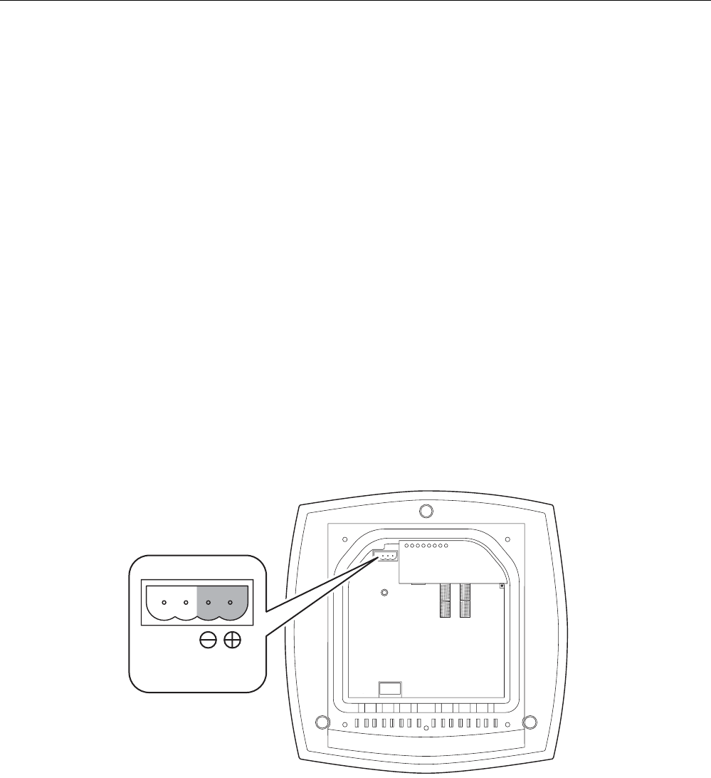
Connecting up
4.4 Connectors for the power supply of the SCALANCE W786
SCALANCE W786-xPRO
Operating Instructions, Release 08/2007, C79000-G8976-C221-02 53
4.4 Connectors for the power supply of the SCALANCE W786
Possible power supplies
The following power supplies are suitable for the SCALANCE W786:
● 48 V DC direct voltage
Use the two-pin connector supplied with the SCALANCE W786.
● 12 - 24 V DC direct voltage
Use the power supply adapter 12 - 24 V DC available as an accessory.
● 110 - 230 V DC direct voltage
Use the power supply adapter 110 - 230 V DC available as an accessory.
● Power over Ethernet (PoE)
If an eight-wire Ethernet cable is used, it is possible to supply power over the four wires
that are not used as data lines. As an alternative, the voltage can be modulated onto the
data lines ("phantom power").
If a Fast Connect Ethernet connector is used to allow cable assembly in the field and due
to its greater mechanical strength, you can only use four-wire cables. In this case, only
phantom power is possible. This does not represent a restriction for the user because
PoE-compatible power equipment always provides both options.
Procedure for connecting the supplied connector for 48 V DC
DC 48 V
Figure 4-4 Position of the opening in the housing for the power supply with the housing cover
removed
Perform the following steps to connect a 48 V DC cable to a SCALANCE W786:
1. Connect the supplied connector to the 48 V DC cable. The figure above shows the
location of the socket in the housing and the contact assignment. The connector is safe
against polarity reversal and can only be inserted in the right-hand half of the housing
When connecting the cores, you should therefore make sure that the connector is
oriented as shown in the following figure.

Connecting up
4.4 Connectors for the power supply of the SCALANCE W786
SCALANCE W786-xPRO
54 Operating Instructions, Release 08/2007, C79000-G8976-C221-02
Figure 4-5 Position of the connector when inserted in the socket of the housing
2. Press the connector into the socket in the housing until it engages.
3. Secure the power cable with a strain relief clamp. For more detailed information on this
topic, refer to the section "Connecting the cables".

Connecting up
4.5 Connecting a power supply adapter
SCALANCE W786-xPRO
Operating Instructions, Release 08/2007, C79000-G8976-C221-02 55
4.5 Connecting a power supply adapter
Input voltage options
The optional power supply adapter is available in two versions:
● Power supply adapter for 12 - 24 V DC direct voltage
● Power supply adapter for 110 - 230 V AC alternating voltage
Note
Applies only to SCALANCE W786-3xx
If a SCALANCE W786-3xx is operated with diversity for three antenna pairs, the power
for 12 - 24 V DC cannot be supplied redundantly. In this case, there is no further opening
in the housing for a second power cable.
How to fit the power supply adapter
WARNING
Danger from line voltage
Power supply cables may only be connected when the power is turned off!
Start up the SCALANCE W786 only after screwing the housing cover in place again so that
protection from touching live parts is restored!
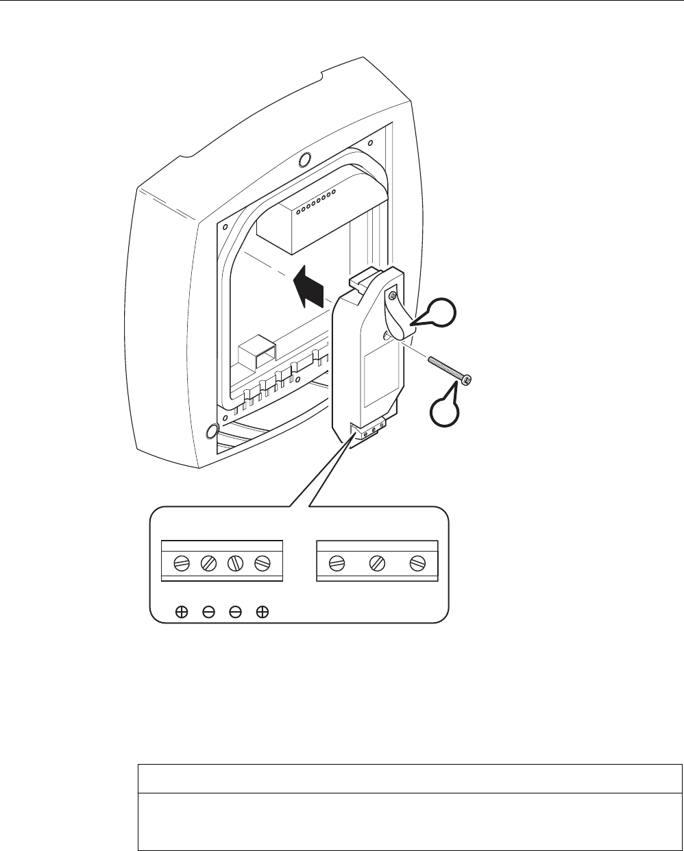
Connecting up
4.5 Connecting a power supply adapter
SCALANCE W786-xPRO
56 Operating Instructions, Release 08/2007, C79000-G8976-C221-02
12 - 24 V 110 - 230 V
L1 M1 M2 L2 L N PE
B
A
Figure 4-6 Using a power supply adapter in a SCALANCE W786
Follow the steps below to fit and connect a power supply adapter:
1. Fit the power supply adapter in the SCALANCE W786 as shown in the figure above. The
connector on the rear of the power supply adapter must engage fully in the socket of the
housing. The entire rear surface of the power supply adapter must make contact with the
inner surface of the SCALANCE W786.
CAUTION
Only use the loop (position B in the figure above) to remove the power supply adapter
from the SCALANCE W786! This prevents the connector skewing on the back of the
power supply adapter and breaking off.
2. Connect the power supply adapter and the SCALANCE W786 with the screw supplied
with the power supply adapter (position A in the figure above).

Connecting up
4.5 Connecting a power supply adapter
SCALANCE W786-xPRO
Operating Instructions, Release 08/2007, C79000-G8976-C221-02 57
3. Connect the cable for the power supply. The assignment of the contacts is illustrated in
the figure above.
4. Secure the power supply cable with a strain relief clamp. For more detailed information
on this topic, refer to the section "Connecting the cables".
How to remove the power supply adapter
Follow the steps below to remove a power supply adapter from a SCALANCE W786:
WARNING
Danger from line voltage
Disconnect power supply cables only when the power to the power supply adapter is turned
off!
1. Disconnect the power supply cable from the power supply adapter.
2. Loosen the securing screw of the power supply adapter (position A in the figure above).
3. Pull the loop (position B in the figure above) to remove the connector on the rear of the
power supply adapter from the socket in the housing and remove the power supply
adapter.
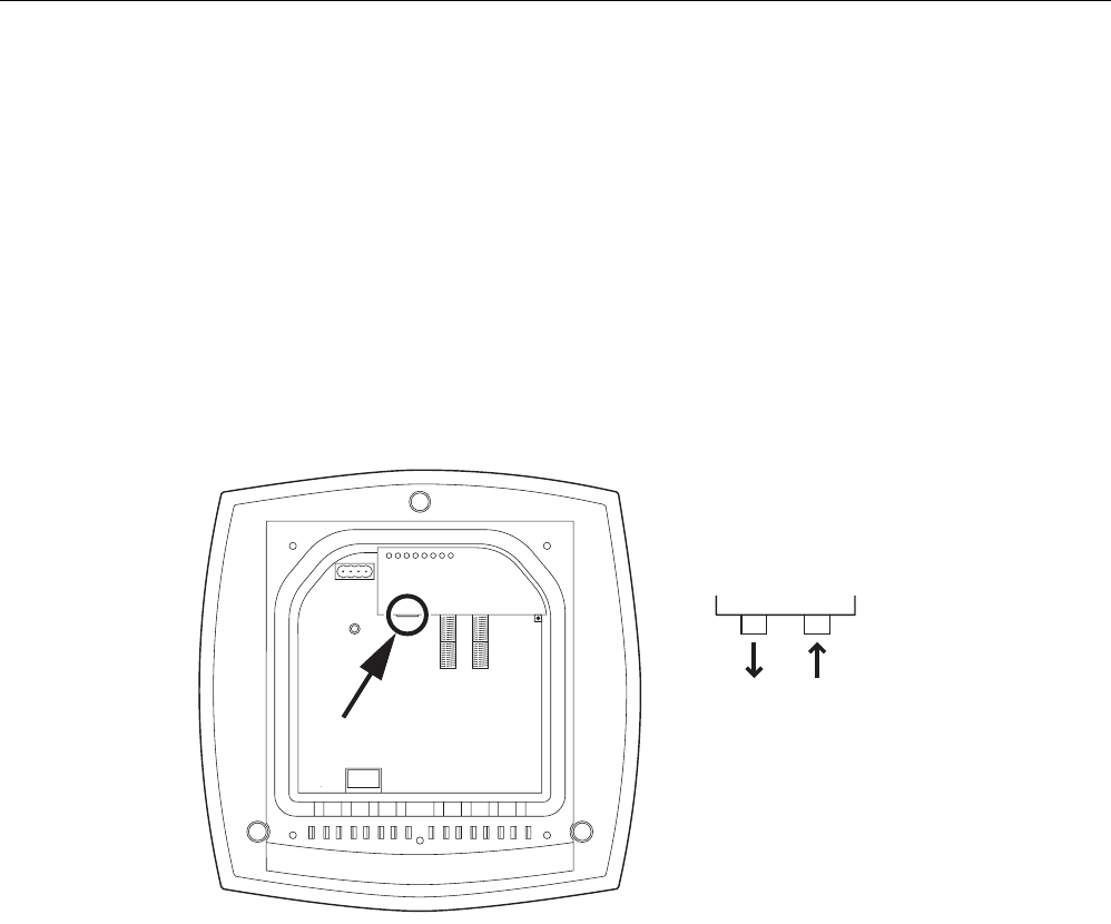
Connecting up
4.6 Connection for Industrial Ethernet
SCALANCE W786-xPRO
58 Operating Instructions, Release 08/2007, C79000-G8976-C221-02
4.6 Connection for Industrial Ethernet
Device variants
With a SCALANCE W786, you have the choice of two Ethernet ports:
● RJ-45 jack
● ST duplex socket for multimode FO cables 1310 nm and a maximum cable length of
3000 m
Procedure for connecting an Ethernet cable
RX
TX
ST-Duplex:
Figure 4-7 Position of the Ethernet port with the housing cover removed
Perform the following steps to connect an Ethernet cable to a SCALANCE W786:
1. Insert the connector of the Ethernet cable in the corresponding socket of the SCALANCE
W786. If you use FO cables, make sure that the transmit and receive lines are correctly
connected. The location of the socket for RX and TX is shown in the figure above.
2. Secure the Ethernet cable with a strain relief clamp. For more detailed information on this
topic, refer to the section "Connecting the cables".
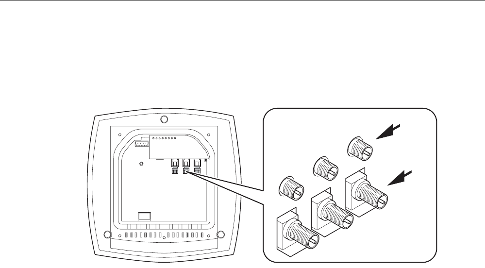
Connecting up
4.7 Connectors for external antennas
SCALANCE W786-xPRO
Operating Instructions, Release 08/2007, C79000-G8976-C221-02 59
4.7 Connectors for external antennas
How to connect external antennas
1
2
3A
B
Figure 4-8 Position of the ports for external antennas with the housing cover removed
For each WLAN port, there are two R-SMA sockets on a SCALANCE W786 to connect
external antennas. The figure above shows how the R-SMA sockets are assigned to the
WLAN ports. With a SCALANCE W786-1PRO, only the socket pair labeled "1" exists; with a
SCALANCE W786-2PRO the sockets labeled "1" and "2" exist.
Perform the following steps to connect a cable for an external antenna to a SCALANCE
W786:
1. Insert the connector on the antenna cable into the R-SMA socket and tighten the sleeve
nut on the socket (key size SW8), tightening torque 0.6 Nm. If you want to use a port for
two antennas, connect the line for antenna "B" first. After connecting the cable for
antenna "A", the socket for "B" is not easy to reach.
2. Screw a terminating resistor to the unused socket if you use only one antenna on a port.
3. Secure the antenna cable(s) with a strain relief clamp. For more detailed information on
this topic, refer to the section "Connecting the cables".
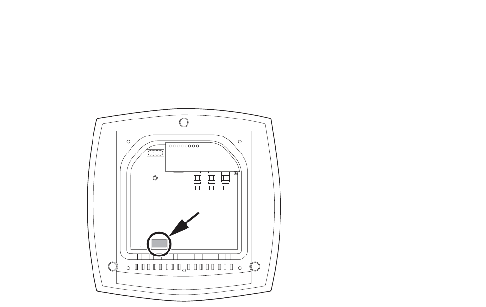
Connecting up
4.8 Inserting / removing the C-PLUG
SCALANCE W786-xPRO
60 Operating Instructions, Release 08/2007, C79000-G8976-C221-02
4.8 Inserting / removing the C-PLUG
Inserting the C-PLUG
Figure 4-9 Location of the C-PLUG with the housing cover removed
The housing of the C-PLUG has a protruding ridge on the long side. The C-PLUG can only
be inserted when this ridge is at the top right. The slot in the SCALANCE W786 has a
corresponding groove at this position. Make sure that the C-PLUG is inserted completely into
the slot.
Removing the C-PLUG
Insert a screwdriver between the right-hand front edge of the C-PLUG and the slot and
release the C-PLUG.
SCALANCE W786-xPRO
Operating Instructions, Release 08/2007, C79000-G8976-C221-02 61
Configuration / project engineering 5
5.1 Technical basics
5.1.1 Spanning Tree
Avoiding loops
The Spanning Tree algorithm detects redundant physical network structures and prevents
the formation of loops by disabling redundant paths. It evaluates the distance and
performance of a connection or bases the decisions on settings made by the user. Data is
then exchanged only over the remaining connection paths.
If the preferred data path fails, the Spanning Tree algorithm then searches for the most
efficient path possible with the remaining nodes.
Root bridge and bridge priority
The identification of the most efficient connection is always related to the root bridge, a
network component that can be considered as a root element of a tree-like network
structure. With the "Bridge Priority" parameter, you can influence the selection of the root
bridge. The computer with the lowest value set for this parameter automatically becomes the
root bridge. If two computers have the same priority value, the computer with the lower MAC
address becomes the root bridge.
Response to changes in the network topology
If nodes are added to a network or drop out of the network, this may affect the optimum path
selection for data packets. To be able to respond to such changes, the root bridge sends
configuration messages at regular intervals. You can set the interval between two
configuration messages with the "Hello Time" parameter.
Keeping configuration information up to date
With the "Max Age" parameter, you set the maximum age of configuration information. If a
bridge has information that is older than the time set in Max Age, it discards the message
and initiates recalculation of the paths.
New configuration data is not used immediately by a bridge but only after the period
specified in the "Forward Delay" parameter. This ensures that operation is started with the
new topology only after all the bridges have the required information.

Configuration / project engineering
5.1 Technical basics
SCALANCE W786-xPRO
62 Operating Instructions, Release 08/2007, C79000-G8976-C221-02
5.1.2 iQoS
Client-specific bandwidth reservation
iQoS (Quality of Service) is technique with which clients are assigned a certain bandwidth.
Due to this assignment, there is a high probability that data transmission to these clients will
be within a defined period. This technique can be useful when response times must be
guaranteed.
5.1.3 Forced Roaming on IP Down
Functional description
"Forced Roaming on IP down" monitors the connection to a specific IP address cyclically.
This is achieved using ICMP packets (Echo Request/Reply or Ping). If the IP connection
aborts; in other words, there is no ping reply from the other end, a deauthentication frame is
sent to all WLAN clients. The relevant WLAN interface is then disabled.
The IP connection continues to be monitored and the WLAN interface is enabled again as
soon as the access point has received a ping reply from the pinged station.
The mechanism makes it possible, for example, to monitor a connection between wireless
clients and a server. If the server can no longer be reached over the access point, the clients
are deauthenticated and the WLAN interface of the access point is disabled. The clients
roam and then connect to a different access point from which the server can be reached. As
soon as the first access point can reach the server again, it re-enables its WLAN interfaces.
5.1.4 Link Check
Device-related connection monitoring
The Link Check function provides device-related connection monitoring for a maximum of ten
wireless nodes logged on at the SCALANCE W78x. This service can be compared with the
link on a wired connection. The function monitors whether the node is available over the
wireless medium. If no packet is received from the node or sent successfully after half of the
configured monitoring time, the SCALANCE W78x attempts to send a test packet to the
node.
5.1.5 Redundancy
Redundant connection between two SCALANCE W78x devices
You can configure two SCALANCE W78x devices with two wireless interfaces so that there
is a redundant wireless connection. The redundancy function causes an automatic failover to

Configuration / project engineering
5.1 Technical basics
SCALANCE W786-xPRO
Operating Instructions, Release 08/2007, C79000-G8976-C221-02 63
the second wireless interface if no data transfer is possible on the first wireless interface.
The user is informed of the status of the redundant connection with the statuses "not
connected", "connected", or "error" (communication error).
5.1.6 IP-Alive
Application-related connection monitoring
The IP-Alive function provides application-related connection monitoring of the wireless link.
It is useful to use IP-Alive on IP connections when it is known that they are used to send
data cyclically. With IP-Alive, you specify a monitoring time for an IP address and a port. If
you do not want to monitor a particular port but rather only the data traffic from a particular IP
address, simply enter 0 in Port. This resets the monitoring with each frame from this IP
address.
In contrast to the Link Check, the SCALANCE W78x does not start any checks until the
monitoring time has elapsed. The SCALANCE W78x checks passively whether
communication took place during the specified monitoring period. As with Link Check, you
can also enter up to ten connections here.
5.1.7 MAC-based communication
Auto Find Adopt MAC / Adopt MAC manually
Frames in the direction from the client to the access point always have the MAC address of
the WLAN interface as the source MAC address. As a result, the learning table at the access
point end always has only the MAC address of the WLAN interface of the client. If the MAC
address of a device connected to the client is adopted, both the MAC-based and the IP-
based frames find their destination in precisely this device.
Other nodes located downstream from the client cannot be reached. The access point
checks whether the destination MAC address matches the MAC addresses of the connected
clients. Since a client can only adopt one MAC address, the access point does not find a
match and discards the packets of several nodes.
Maximum possible number of MAC nodes downstream from the client: 1
Notes on the "Auto Find Adopt MAC" setting:
● As long as there is no link on the Ethernet interface, the device uses the MAC address of
the Ethernet interface so that it can be reached in this status. In this status, the device
can be found using the Primary Setup Tool.
● As soon as there is a link on the Ethernet interface, the device adopts the source MAC
address of the first received frame.

Configuration / project engineering
5.1 Technical basics
SCALANCE W786-xPRO
64 Operating Instructions, Release 08/2007, C79000-G8976-C221-02
Note
From the moment that the device adopts another MAC address (whether manually or
automatically), the device no longer responds to queries of the Primary Setup Tool when
the query is received over the WLAN interface. Queries of the PST over the Ethernet
interface continue to be replied to.
Adopt Own MAC (only for W746-1 and W747-1 or W746-1PRO and W747-1RR and W78x in client
mode)
If IP-based frames need to be sent to a device connected downstream from the client, the
default setting Adopt Own Mac can be retained. The client registers with the MAC address of
its Ethernet adapter. The IP packets are broken down according to an internal table and
forwarded to the connected devices (IP mapping).
Communication at the MAC address level (ISO/OSI layer 2) is then only possible with a
component downstream from the client if its MAC address was adopted by the client.
Maximum possible number of MAC nodes downstream from the client: 1
Layer 2 tunneling (only for W746-1 and W747-1 or W746-1PRO and W747-1RR and W78x in client
mode)
With layer 2 tunneling, the client provides information about the devices downstream from it
when it registers with an access point. This makes it possible to enter the MAC addresses of
these devices in the learning table of the access point. The access point can forward MAC-
based frames for the devices downstream from the client to the appropriate client.
In much the same way as with WDS, a separate port is created for the L2T client over which
the Ethernet frames are sent without changing the destination MAC address.
Maximum possible number of MAC nodes downstream from the client: 8
5.1.8 IP-based communication
IP mapping (only for W746-1 and W747-1 or W746-1PRO and W747-1RR and W78x in client mode)
If there is more than one device connected downstream from the client and these should
only be addressed with IP frames, you can implement WLAN access for several devices with
one client. With IP mapping, the client maintains a table with the assignment of MAC
address and IP address to forward incoming IP frames to the correct MAC address.
Maximum possible number of IP nodes downstream from the client: 8

Configuration / project engineering
5.2 Assignment of an IP address
SCALANCE W786-xPRO
Operating Instructions, Release 08/2007, C79000-G8976-C221-02 65
5.2 Assignment of an IP address
5.2.1 Structure of an IP address
Address classes to RFC 1518 and RFC 1519
IP address range Max. number of networks Max. number of
hosts/network
Class CIDR
1.x.x.x through 126.x.x.x 126 16777214 A /8
128.0.x.x through 191.255.x.x 16383 65534 B /16
192.0.0.x through 223.255.255.x 2097151 254 C /24
Multicast groups D
Reserved for experiments E
An IP address consists of 4 bytes. Each byte is represented in decimal, with a dot separating
it from the previous one. This results in the following structure, where XXX stands for a
number between 0 and 255:
XXX.XXX.XXX.XXX
The IP address is made up of two parts, the network ID and the host ID. This allows different
subnets to be created. Depending on the bytes of the IP address used as the network ID and
those used for the host ID, the IP address can be assigned to a specific address class:
Subnet mask
The bits of the host ID can be used to create subnets. The leading bits represent the address
of the subnet and the remaining bits the address of the host in the subnet.
A subnet is defined by the subnet mask. The structure of the subnet mask corresponds to
that of an IP address. If a "1" is used at a bit position in the subnet mask, the bit belongs to
the corresponding position in the IP address of the subnet address, otherwise to the address
of the computer.
Example of a class B network:
The standard subnet address for class B networks is 255.255.0.0; in other words, the last
two bytes are available for defining a subnet. If 16 subnets must be defined, the 3rd byte of
the subnet address must be set to 11110000 (binary notation). In this case, this results in the
subnet mask 255.255.240.0.
To find out whether two IP addresses belong to the same subnet, the two IP addresses and
the subnet mask are ANDed bit by bit. If both logic operations have the save result, both IP
addresses belong to the same subnet, for example, 141.120.246.210 and 141.120.252.108.
Outside the local area network, the distinction between network ID and host ID is of no
significance, in this case packets are delivered based on the entire IP address.
Note
In the bit representation of the subnet mask, the "ones" must be set left-justified (there must
be no "zeros" between the "ones").

Configuration / project engineering
5.2 Assignment of an IP address
SCALANCE W786-xPRO
66 Operating Instructions, Release 08/2007, C79000-G8976-C221-02
5.2.2 Initial assignment of an IP address
Configuration options
An initial IP address for a SCALANCE W-700 cannot be assigned using Web Based
Management or the Command Line Interface over Telnet because these configuration tools
require that an IP address already exists.
The following options are available to assign an IP address to an unconfigured device
currently without an IP address:
● DHCP (default)
● STEP 7
● NCM PC
● Primary Setup Tool
Note
DHCP is enabled as default and following "Restore Factory Defaults and Restart". If a DHCP
server is available in the local area network, and this responds to the DHCP request of a
SCALANCE W-700, the IP address, subnet mask and gateway are assigned automatically
when the device first starts up. "Reset to Memory Defaults" does not delete an IP address
assigned either by DHCP or by the user.
5.2.3 Address assignment with DHCP
Properties of DHCP
DHCP (Dynamic Host Configuration Protocol) is a method for automatic assignment of IP
addresses. It has the following characteristics:
● DHCP can be used both when a device starts up and during operation.
● The assigned IP address remains valid only for a particular time known as the lease time.
Once this period has elapsed, the client must either request a new IP address or extend
the lease time of the existing IP address.
● There is normally no fixed address assignment; in other words, when a client requests an
IP address again, it normally receives a different address from the previous address. It is,
however possible, to configure the DHCP server so that it assigns a fixed address.

Configuration / project engineering
5.2 Assignment of an IP address
SCALANCE W786-xPRO
Operating Instructions, Release 08/2007, C79000-G8976-C221-02 67
Note
DHCP uses a mechanism with which the IP address is assigned for only a short time
(lease time). If the device does not reach the DHCP server with a new request on expiry
of the lease time, the assigned IP address, the subnet mask and the gateway are
changed to static entries.
The device therefore remains accessible under the last assigned IP address even without
a DHCP server. This is not the standard behavior of office devices but is necessary for
problem-free operation of the plant.
Since the DHCP client also sends a RELEASE to the server, the server can assign this
address to a further device so that inconsistencies can occur within the network.
Remedy:
After disabling DHCP, you should therefore
• change the IP address of the device to an address not assigned by DHCP
or
• remove the IP address assigned to the device from the address pool of the DHCP
server.
Working with a mixture of dynamic address assignment and statically assigned
addresses is not advisable.
5.2.4 Address assignment with the Primary Setup Tool
Introduction
The PST (Primary Setup Tool) is capable of assigning such an address to unconfigured
devices without an IP address.
Prerequisite
This is possible only when the devices have a default Ethernet (MAC) address and are
reachable online in the network.
Note
For more detailed information, refer to the Primary Setup Tool configuration manual.
You will find the PST at Siemens Automation and Drives Service & Support on the Internet
under entry ID 19440762. The URL for this entry is:
http://support.automation.siemens.com/WW/view/en/19440762

Configuration / project engineering
5.3 The wizards of Web Based Management
SCALANCE W786-xPRO
68 Operating Instructions, Release 08/2007, C79000-G8976-C221-02
5.3 The wizards of Web Based Management
5.3.1 Introduction
Principle of Web Based Management
The SCALANCE W-700 has an integrated HTTP server for Web Based Management. If the
SCALANCE W-700 is accessed by an Internet browser, it returns HTML pages to the client
computer as specified by the selections made by the user.
Users enter the configuration data in the HTML pages sent by the SCALANCE W-700. The
SCALANCE W-700 evaluates this information and generates response pages dynamically.
The great advantage of this method is that apart from a Web browser, no special software is
required on the client.
Requirements for Web Based Management
Once you have assigned an IP address with the Primary Setup Tool, you can continue to
configure the device with Web Based Management.
To use Web Based Management, you should ideally have a wired network connection
between the SCALANCE W-700 and the client computer. In principle, it is also possible to
use Web Based Management over a wireless network, however the SCALANCE W-700 can
be set so that access over a wireless network is disabled.
We recommend that you use the Microsoft Internet Explorer Version 5.5 or higher or Mozilla
Firefox Version 1.5 or higher.
All the pages of Web Based Management require JavaScript. Make sure that your browser
settings allow this.
Since Web Based Management is HTTP-based, you will have to allow access to Port 80 or
Port 443 for HTTPS if you have a firewall installed.
Note
The screenshots in this section were created using the Microsoft Internet Explorer version
6.0. If you use a different browser (for example Mozilla), the appearance of the menus may
differ.
5.3.2 Starting Web Based Management and logging on
Procedure
Follow the steps below to establish a connection to a device using a Web browser:
1. Enter the IP address or the URL of the SCALANCE W-700 in the address box of the Web
browser. If there is a problem-free connection to the SCALANCE W-700, the Logon
dialog of Web Based Management is displayed:
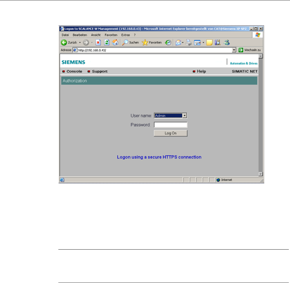
Configuration / project engineering
5.3 The wizards of Web Based Management
SCALANCE W786-xPRO
Operating Instructions, Release 08/2007, C79000-G8976-C221-02 69
2. Open the "User name" drop-down list box and select the "Admin" entry if you want to
change settings of the SCALANCE W-700 (read and write access). If you select the
"User" entry, you will only have read access to the configuration data of the
SCALANCE W-700.
3. Enter your password. If you have not yet set a password, the default passwords as
shipped apply: Enter admin if you selected "Admin" as the user name or user if you
selected "User".
4. Click the "Log On" button to start the logon.
Note
For the US variant of the SCALANCE W-700, the password for the "admin" user has
been changed; it can, however, be obtained from Siemens Support by specialists for
professional WLAN installation.
Connection over HTTPS
Web Based Management also allows you to connect to the device over the secure
connection of the HTTPS protocol.
Use the "Logon using a secure HTTPS connection" link in the logon screen (see figure
above) or enter "https://" and the IP address of the SCALANCE W7xx in the address box of
the Web browser and confirm with Enter. The "Security Alert" warning is displayed and asks
you whether you want to continue the action. Confirm with "YES". The Login dialog of Web
Based Management opens.

Configuration / project engineering
5.3 The wizards of Web Based Management
SCALANCE W786-xPRO
70 Operating Instructions, Release 08/2007, C79000-G8976-C221-02
5.3.3 Selecting the wizards
Basic Wizard, Security Wizard and iPCF-Wizard
Web Based Management provides several wizards that allow straightforward commissioning
without detailed knowledge of wireless technology. A wizard consists of a series of screens
in which you enter the basic configuration data.
The following wizards are available:
● Basic Wizard
For general settings to ensure the basic functionality of the device.
● Security Wizard
The wizard for the security settings supports you when setting security-related
parameters.
● iPCF Wizard
This wizard is available for configuring iPCF (industrial Point Coordination Function).
Note
The iPCF Wizard is available only for the following devices:
• SCALANCE W78x-xRR
• SCALANCE W747-1
• SCALANCE W747-1RR
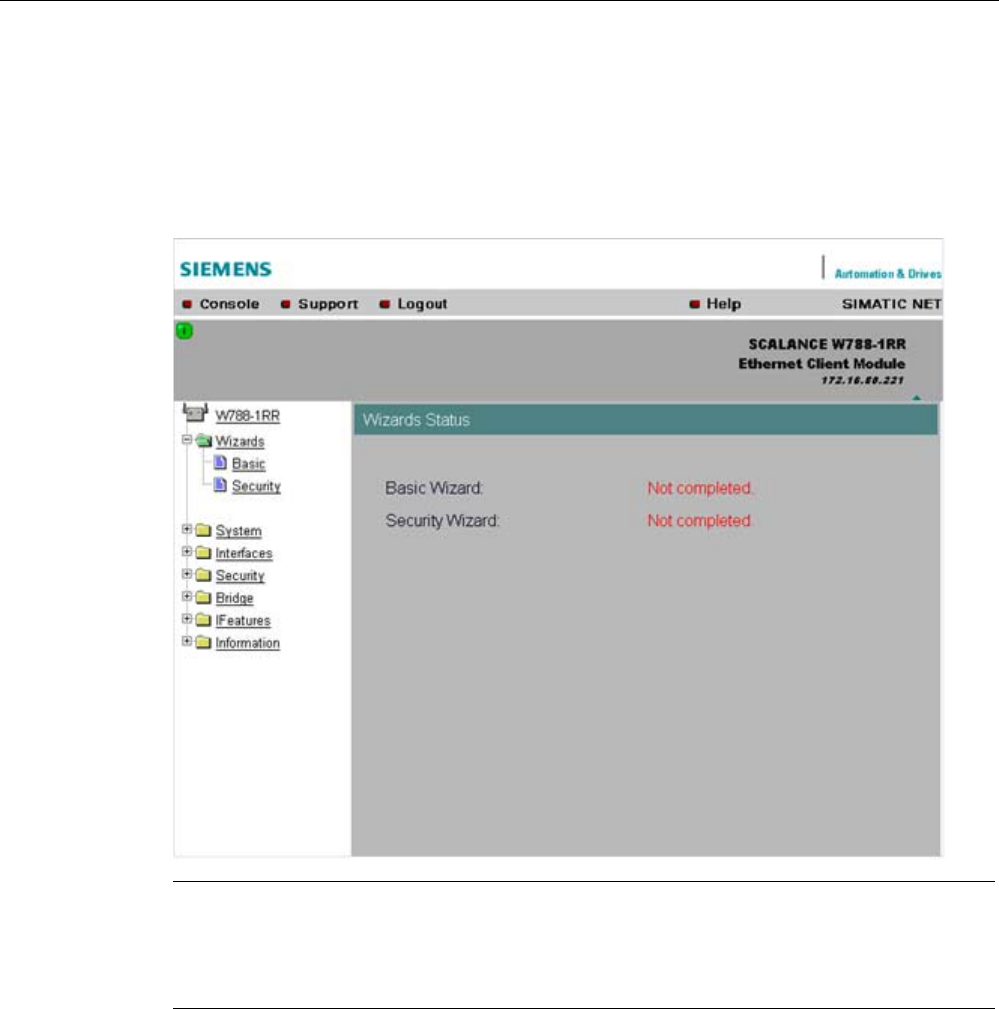
Configuration / project engineering
5.3 The wizards of Web Based Management
SCALANCE W786-xPRO
Operating Instructions, Release 08/2007, C79000-G8976-C221-02 71
Wizard status
After selecting the "Wizards" menu on the left-hand side of the dialog, the status of the
wizards is displayed. When you have worked through a wizard completely, "Done" is
displayed as the status. When you have worked through all the wizards, the "Wizards" entry
also moves to the bottom end of the menu.
Note
Some pages of the wizards have a different content in access point mode and "Client" mode.
In this case, there is a separate description for the alternatives.
You can specify the mode in the "System" menu.
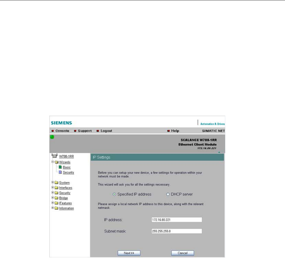
Configuration / project engineering
5.4 Basic Wizard
SCALANCE W786-xPRO
72 Operating Instructions, Release 08/2007, C79000-G8976-C221-02
5.4 Basic Wizard
5.4.1 IP settings
Description
One of the basic steps in configuration of an Ethernet device is setting the IP address. The
IP address identifies a device in the network uniquely. On this page, you enter the
information for the IP configuration of the SCALANCE W-700.
Specified IP address / DHCP server
check boxes
There are two methods of assigning IP addresses to devices: The IP address can be set as
a fixed permanent address or can be obtained dynamically from a DHCP server. Select
"Specified IP Address" if you do not use a DHCP server.
IP address
input box
The IP address of the SCALANCE W-700. Here, you enter an address that is unique within
the network.
Subnet mask
input box
The subnet mask specifies the range of addresses within which communication can take
place.
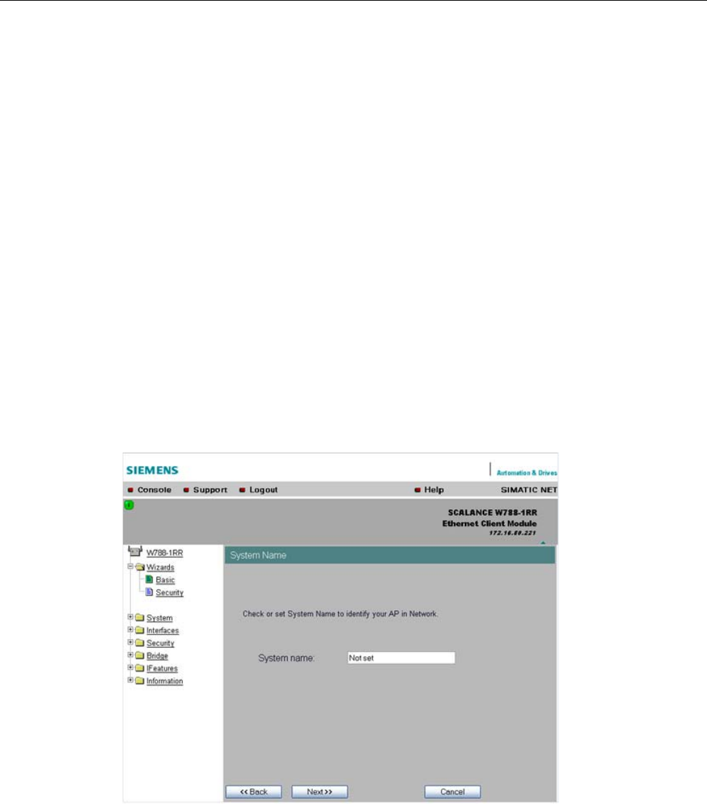
Configuration / project engineering
5.4 Basic Wizard
SCALANCE W786-xPRO
Operating Instructions, Release 08/2007, C79000-G8976-C221-02 73
The four numbers of an IP address separated by periods are interpreted as a bit pattern. If a
one is set at a bit position within the subnet mask, this means that only devices with an IP
address that matches the IP address of the SCALANCE W-700 at this bit position can
communicate with the SCALANCE W-700 management agent.
Example
Let us assume that the IP address of the SCALANCE W-700 is set to 192.168.147.189 and
the subnet mask is set to 255.255.255.0. The bit pattern for 255 is 1111 1111. This means
that the bit pattern of the first number of the IP address of a communication partner must
match the bit pattern of the SCALANCE W-700 exactly at this point. The same applies to the
second and third parts of the IP address. The IP address of a communication partner must
therefore start with 192.168.147. The bit pattern of 0 is 0000 0000. This means that the bit
pattern of the last part of the IP address of the partner device does not need to match the
address of the SCALANCE W-700 at any point; in other words, it can be any number.
5.4.2 System name
Description
The system name identifies a network node but means more to the user than the IP address.
System name
input box
In this box, you enter the system name for your SCALANCE W-700. This parameter
corresponds to the "sysName" SNMP parameter. The system name can be up to a
maximum of 255 characters long. If you also want to use this parameter for WDS or
redundancy, the maximum length is 30 characters.
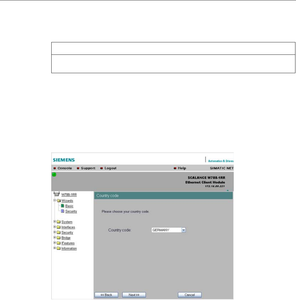
Configuration / project engineering
5.4 Basic Wizard
SCALANCE W786-xPRO
74 Operating Instructions, Release 08/2007, C79000-G8976-C221-02
5.4.3 Country code
NOTICE
The correct country setting is mandatory for operation complying with the approvals.
Selecting a country different from the country of use can lead to legal prosecution!
Description
Some countries have different frequency band divisions for WLAN communication. The
regulations for maximum output power also differ from country to country. When you
configure the SCALANCE W-700, you specify which local regulations are relevant for your
location. You do this with the "Country Code" parameter.
Country Code
drop-down list box
In this list box, you select the country in which the SCALANCE W-700 will be operated. You
do not need to know the data for the specific country, the correct channel division and
transmit power are set by the SCALANCE W-700 according to the country you select.
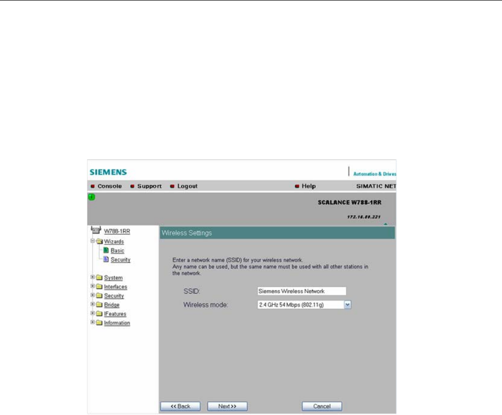
Configuration / project engineering
5.4 Basic Wizard
SCALANCE W786-xPRO
Operating Instructions, Release 08/2007, C79000-G8976-C221-02 75
5.4.4 Wireless settings in access point mode
Description
On this page, you specify the configuration of the wireless network. This includes the
network name and the transmission mode. If you configure a SCALANCE W78x with several
WLAN interfaces, this page is displayed for each WLAN interface. You can make different
settings for each WLAN interface.
SSID
input box
Enter the name of your network in this box. The SCALANCE W78x allows all characters
except the percent character for the SSID. To ensure compatibility with partner devices, you
should, however, not use any characters that are peculiar to a particular language (for
example special German characters ä, ö etc.) or special characters in general. The string for
SSID can be a maximum of 32 characters long.
Wireless Mode
drop-down list box
Select a wireless mode that is supported by all partner devices. if you are using a
SCALANCE W78x with several WLAN interface, it is sometimes an advantage if you set a
different transmission mode for each WLAN interface. This provides ideal support for
different clients. The effect of the "802.11.b" or "802.11.g" setting is that all the settings in the
"Advanced G" menu are taken into account as far as possible while retaining compatibility
with devices conforming with IEEE 802.11 b.
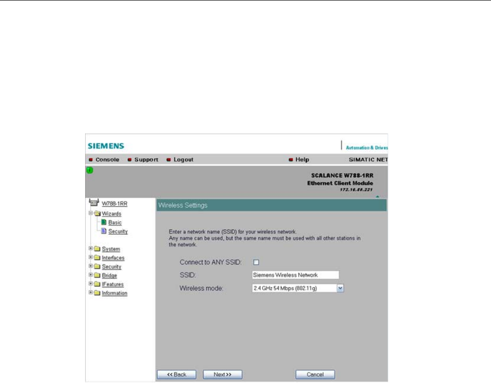
Configuration / project engineering
5.4 Basic Wizard
SCALANCE W786-xPRO
76 Operating Instructions, Release 08/2007, C79000-G8976-C221-02
5.4.5 Wireless settings in client mode
Description
In "Client" mode, you will also see the "Connect to ANY SSID" check box. The other settings
correspond to those of the access point mode.
Connect to ANY SSID
check box
When this check box is selected, the client connects to the access point that
allows the best possible data transfer and to which a connection is permitted based on the
security settings.
5.4.6 Adopt MAC Address settings (only for clients or access points in client mode)
Assigning the MAC address
A MAC address must be specified for the device connected to the Ethernet port of the
SCALANCE W-700 client before it can be reached. This MAC address is used by the client
for wireless communication with the access point.
There are several ways in which this can be done:
● If there is precisely one MAC address to be served downstream from the client, there are
two ways of doing this:

Configuration / project engineering
5.4 Basic Wizard
SCALANCE W786-xPRO
Operating Instructions, Release 08/2007, C79000-G8976-C221-02 77
– Automatically
The client adopts the source MAC address of the first frame that it receives over the
Ethernet interface.
– Manual entry by the user.
● If there are up to eight MAC addresses to be served downstream from the client, "Layer 2
Tunneling" can be used:
This setting meets the requirements of industrial applications in which MAC address-based
communication is required with several devices downstream from the client. Clients with this
setting cannot connect to standard Wi-Fi devices and SCALANCE W700 access points with
firmware V3.0 or older.
Note
The layer 2 tunneling setting is available only with the following model variants:
• SCALANCE W78x in client mode
• SCALANCE W746-1PRO
• SCALANCE W746-1
• SCALANCE W747-1RR
• SCALANCE W747-1
Note
IP mapping table
If layer 2 tunneling is configured for a client, the IP mapping table is not displayed.
The SCALANCE W746-1PRO or W746-1 and SCALANCE W747-1RR or W747-1 devices as
well as SCALANCE W78x devices operating in client mode can provide access to a wireless
network for several Ethernet devices (IP mapping). For an access point with MAC filtering,
only one MAC address is visible to the SCALANCE W700 client, there can be no filtering
according to the MAC addresses of the Ethernet devices.
Note
Configuration limits
Several MAC nodes (for example PROFINET IO devices) are connected to the Ethernet
interface of a client module and the "AdoptMAC" parameter is set to "Layer 2 tunneling". The
following configuration limits apply for reliable communication:
• No more than 8 nodes may be connected downstream from the L2T client.
• When transferring cyclic PROFINET IO data in iPCF mode, remember that the sum of the
user data of all nodes connected to the client must not exceed a value of 2,300 bytes per
cycle. This also includes the frame header. A SIMATIC user must therefore take into
account not only the net data during configuration but also the headers.
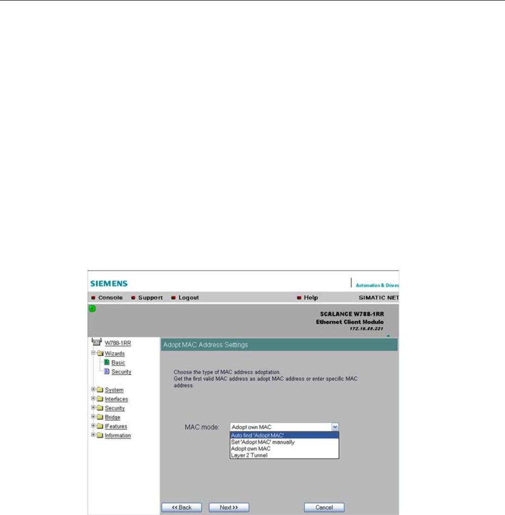
Configuration / project engineering
5.4 Basic Wizard
SCALANCE W786-xPRO
78 Operating Instructions, Release 08/2007, C79000-G8976-C221-02
MAC mode
drop-down list box
Here, select how the SCALANCE W700 client obtains a MAC address. The following are
possible:
● Auto find 'Adopt MAC'
The SCALANCE W700 client automatically adopts the source MAC address of the first
frame that it receives over the Ethernet interface.
● Set 'Adopt MAC' manually
You enter the MAC address manually.
● Adopt own MAC (not for SCALANCE W744-1PRO / W744-1)
As a client, the SCALANCE W700 uses the MAC address of the Ethernet interface for the
WLAN interface.
● Layer 2 Tunneling (not for SCALANCE W744 1PRO / W744-1)
As a client, the SCALANCE W700 uses the MAC address of the Ethernet interface for the
WLAN interface. The network is also informed of the MAC addresses connected to the
Ethernet interface of the SCALANCE W700 client.
Adopt MAC
input box
If you have selected the "Set 'Adopt MAC' manually" check box, here you will need to enter
the MAC address of the device connected over Ethernet to the SCALANCE W700 operating
in client mode.
If you do not want layer 2 communication to be handled over the SCALANCE W700
operating in client mode, but only want higher-layer IP-based frames sent to one or more
connected devices, you can also leave the default setting "Adopt Own Mac". In this mode,
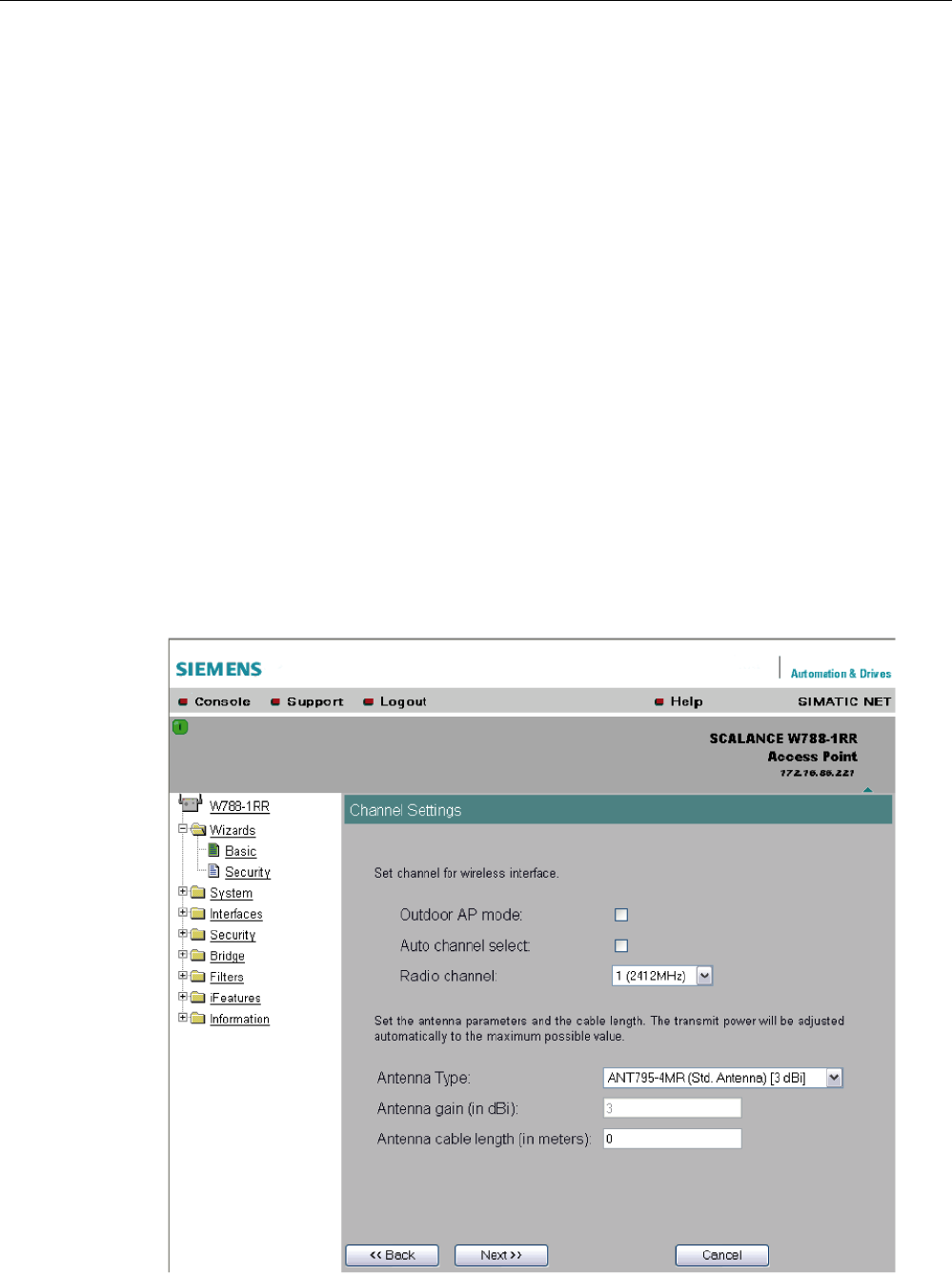
Configuration / project engineering
5.4 Basic Wizard
SCALANCE W786-xPRO
Operating Instructions, Release 08/2007, C79000-G8976-C221-02 79
the client registers with the MAC address of its Ethernet adapter. The IP packets are broken
down according to an internal table and forwarded to the connected devices.
The "Adopt MAC" box is hidden in the "Auto find 'Adopt MAC' " and "Layer 2 Tunneling"
modes.
5.4.7 Channel settings (in access point mode only)
Description
The SCALANCE W78x uses a specific channel within the frequency band for
communication. You can either set this channel specifically or configure the
SCALANCE W78x so that the channel is selected automatically. A specific channel must be
set, for example, in the following situations:
● Communication suffers from interference from another device (for example microwaves)
or another wireless network.
● Use of the redundancy function. In this case, two well spaced channels or two different
frequency bands must be selected.
● Use of WDS. In this case, select a problem-free channel that is also used by the WDS
partner.

Configuration / project engineering
5.4 Basic Wizard
SCALANCE W786-xPRO
80 Operating Instructions, Release 08/2007, C79000-G8976-C221-02
Outdoor AP mode
check box
Select this check box to enable the outdoor AP mode.
Auto Channel Select
check box
Select this check box if you do not have any particular requirements regarding channel
selection.
Radio Channel
drop-down list box
Here, you select a channel suitable for your application. You can only select from this list if
the "Auto Channel Select" check box is not selected. The entries in the list box depend on
the previous selection made in the "Country code" box and on the mode (IEEE 802.11a,
IEEE 802.11b, IEEE 802.11g, IEEE 802.11h).
Antenna Type
drop-down list box (only for devices with external antennas)
Select the type of external antenna connected to the device.
Antenna gain (in dBi)
input box (only for devices with external antennas)
If you selected the "User defined" entry in the "Antenna Type" drop-down list box, you can
enter the antenna gain manually in the unit "dBi".
Antenna cable length (in meters)
input box (only for devices with external antennas)
Enter the cable length between the device and the external antenna in meters.
Note
When the devices are supplied, the WLAN interfaces are deactivated (exception IWLAN/PB-
Link PN IO). You can use these interfaces after you have worked through the Basic Wizard.
NOTICE
If you use a second or third WLAN interface, make sure that you have adequate channel
spacing.
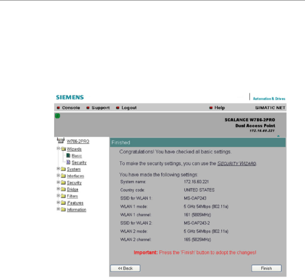
Configuration / project engineering
5.4 Basic Wizard
SCALANCE W786-xPRO
Operating Instructions, Release 08/2007, C79000-G8976-C221-02 81
5.4.8 Closing the Basic Wizard
Description
This page displays the parameters you have selected when you have completed all the
entries for the basic configuration. "Adopt MAC Address" is displayed only for an access
point in client mode.
Finish
button
Click this button to close the Basic Wizard and to log on again with the modified IP address.

Configuration / project engineering
5.5 Security Wizard
SCALANCE W786-xPRO
82 Operating Instructions, Release 08/2007, C79000-G8976-C221-02
5.5 Security Wizard
5.5.1 Introduction
With the Security Wizard, you can specify security-related parameters without detailed
knowledge of security technology in wireless networks.
Note
The SCALANCE W700 can be operated even if you do not set the security parameters.
Depending on the properties of your network, there is then, however, an increased risk of
unauthorized access. You should therefore work through all the pages of the Security
Wizard, so that you have at least basic security functions.
5.5.2 Security settings
Password
First, set a new admin password. Enter the string twice in the text boxes of this page. The
password can be up to a maximum of 31 characters long.
When assigning the password, ASCII code 0x20 to 0x7e is used. The following characters
are supported:
Numbers 0...9
Letters abcdefghijklmnopqrstuvwxyz ABCDEFGHIJKLMNOPQRSTUVWXYZ
Special characters !"#$%&'()*+,-./:;<=>?@[\]^_`{|}~ and the blank
Until you set a password, the defaults set in the factory apply: The default password for the
"admin" user is "admin". You can use the wizards only if you log on as administrator.
Note
For the US variant of the SCALANCE W-700, the password for the "admin" user has been
changed; it can, however, be obtained from Siemens Support by specialists for professional
WLAN installation.
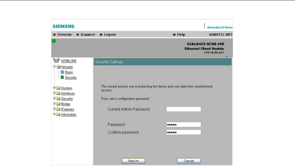
Configuration / project engineering
5.5 Security Wizard
SCALANCE W786-xPRO
Operating Instructions, Release 08/2007, C79000-G8976-C221-02 83
5.5.3 Security settings for the management interfaces
Protocols for configuration
On this page, you specify the protocols with which you access the configuration of the
SCALANCE W700. All protocols with a selected check box can be used for configuration.
You should only select protocols that you actually use.
The protocol settings only take effect after exiting the Security Wizard and restarting. Even
after selecting the "Web Based Management" entry, you still have the option of returning to
earlier pages or exiting the wizard.
Specifying the network type for configuration
It is easier to restrict access to a wired network than to a wireless network. Web Based
Management allows access to the SCALANCE W700 for configuration to be restricted to
computers linked to the SCALANCE W700 by a cable. If you require this, check the box at
the bottom of the page.
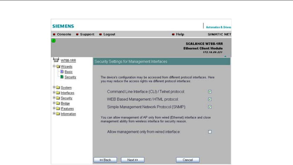
Configuration / project engineering
5.5 Security Wizard
SCALANCE W786-xPRO
84 Operating Instructions, Release 08/2007, C79000-G8976-C221-02
5.5.4 Security settings for the SNMP protocol
Access permissions when using the SNMP protocol
When using the SNMP protocol, you specify access permissions by means of the community
string. A community string effectively combines the function of user name and password in
one string; different community strings are defined for read and write permissions. More
complex and more secure authentications are possible only in some SNMPv2 variants and in
SNMPv3.
To preserve security, you should not use the default values "public" or "private".
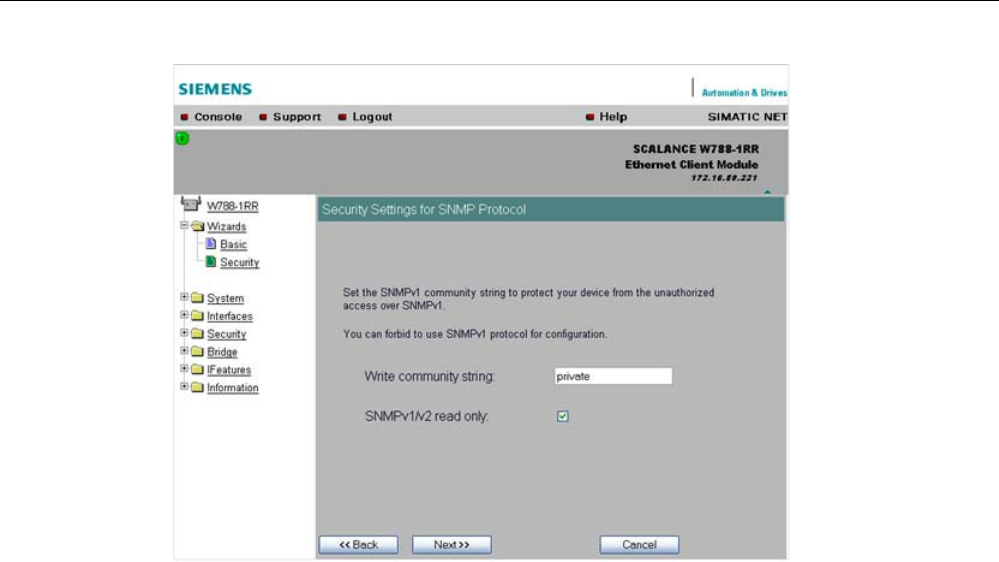
Configuration / project engineering
5.5 Security Wizard
SCALANCE W786-xPRO
Operating Instructions, Release 08/2007, C79000-G8976-C221-02 85
Write Community String
input box
Here, you enter the write community string (maximum of 63 characters) for the SNMP
protocol.
Read Only
check box
If you select this check box, only read access is possible with the SNMP protocol V1 or V2c.
5.5.5 Security settings for WLAN (page 1, only in access point mode)
Description
On this page, you make the security settings, including, for example, the authentication and
encryption. If you configure a model with several wireless adapters, this page appears for
each adapter. You can make different settings for each wireless adapter.
Network-specific security settings
On the first page of the security settings, you select settings that apply regardless of
protocol-specific restrictions. The basic measures for securing a network against
unauthorized access involve
● allowing only certain clients (those that have entered the network name (SSID) of the AP)
to communicate with the SCALANCE W78x.
● excluding clients that communicate over wireless connections from the wired part of the
network.
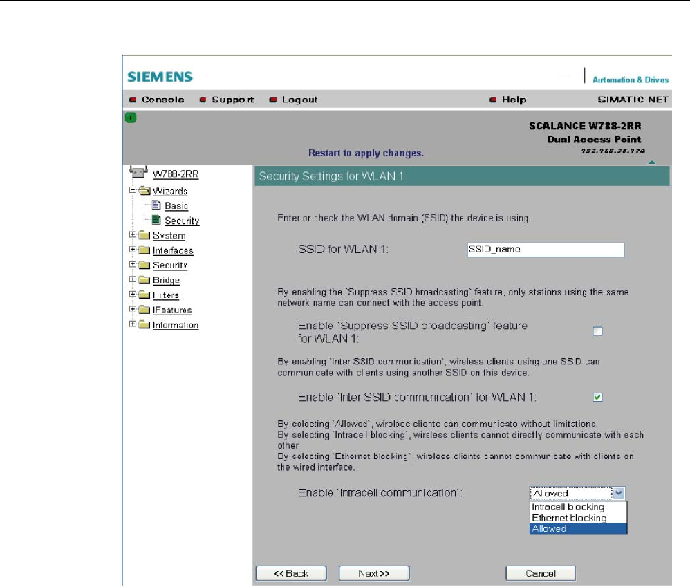
Configuration / project engineering
5.5 Security Wizard
SCALANCE W786-xPRO
86 Operating Instructions, Release 08/2007, C79000-G8976-C221-02
SSID input box for WLAN 1
Enter the name of your network in this box (maximum of 255 characters, 32 characters if you
use the redundancy function). To avoid any possible conflicts with settings for a specific
locale on the computer, the name should not include any special German characters (ö, ä
etc.).
Enable 'Suppress SSID broadcasting' feature for WLAN 1
Selecting this option means that the SSID is not visible for other devices. As a result, only
stations for which the same network name was configured as for the SCALANCE W78x can
connect to the SCALANCE W78x.

Configuration / project engineering
5.5 Security Wizard
SCALANCE W786-xPRO
Operating Instructions, Release 08/2007, C79000-G8976-C221-02 87
Note
Since no encryption is used for the SSID transfer, this function can only provide basic
protection against unauthorized access. The use of an authentication method (for example
WPA (RADIUS) or WPA-PSK if this is not possible) provides higher security. You must also
expect that certain end devices may have problems with access to a hidden SSID.
Enable 'Inter SSID communication' option for WLAN 1
Selecting this option allows communication between WLAN clients registered at different
SSIDs of an access point.
Example 1 A SCALANCE W786-3PRO was defined with different SSIDs.
Example 2 A SCALANCE W788-1PRO is used with multiple SSIDs.
Note
On a SCALANCE W78x-2/3xx, the Inter SSID Communication function must be enabled on
all WLAN interfaces or on all VAPs to allow communication between the clients with different
SSIDs.
Note
If VLANs are configured for the SSIDs, this setting can prevent communication between the
SSIDs according to the VLAN rules.
Enable 'Intracell communication' list box
● Intracell blocking
This setting prevents WLAN client communication within an SSID.
● Ethernet blocking
This setting prevents WLAN client communication over the Ethernet interface of the
access point.
● Disabled
This setting enables both WLAN client communication within an SSID as well as WLAN
client communication over the Ethernet interface.
Overview of the communication options
To illustrate the situation, there is an overview of the effects of the "Inter SSID
communication" and "Intracell communication" settings below.

Configuration / project engineering
5.5 Security Wizard
SCALANCE W786-xPRO
88 Operating Instructions, Release 08/2007, C79000-G8976-C221-02
Settings Possible communication
Inter SSID
communication
Intracell
communication
within
an SSID
with another SSID to the Ethernet
network
Enabled Allowed x x x
Enabled Intracell
blocking
x x
Enabled Ethernet
blocking
x x
Disabled Allowed x x
Disabled Intracell
blocking
x
Disabled Ethernet
blocking
x
5.5.6 Security settings for WLAN (page 2)
Predefined security levels
Authentication and encryption are tried and tested methods for increasing security in
networks. Web Based Management provides four predefined security levels that specify
suitable methods.
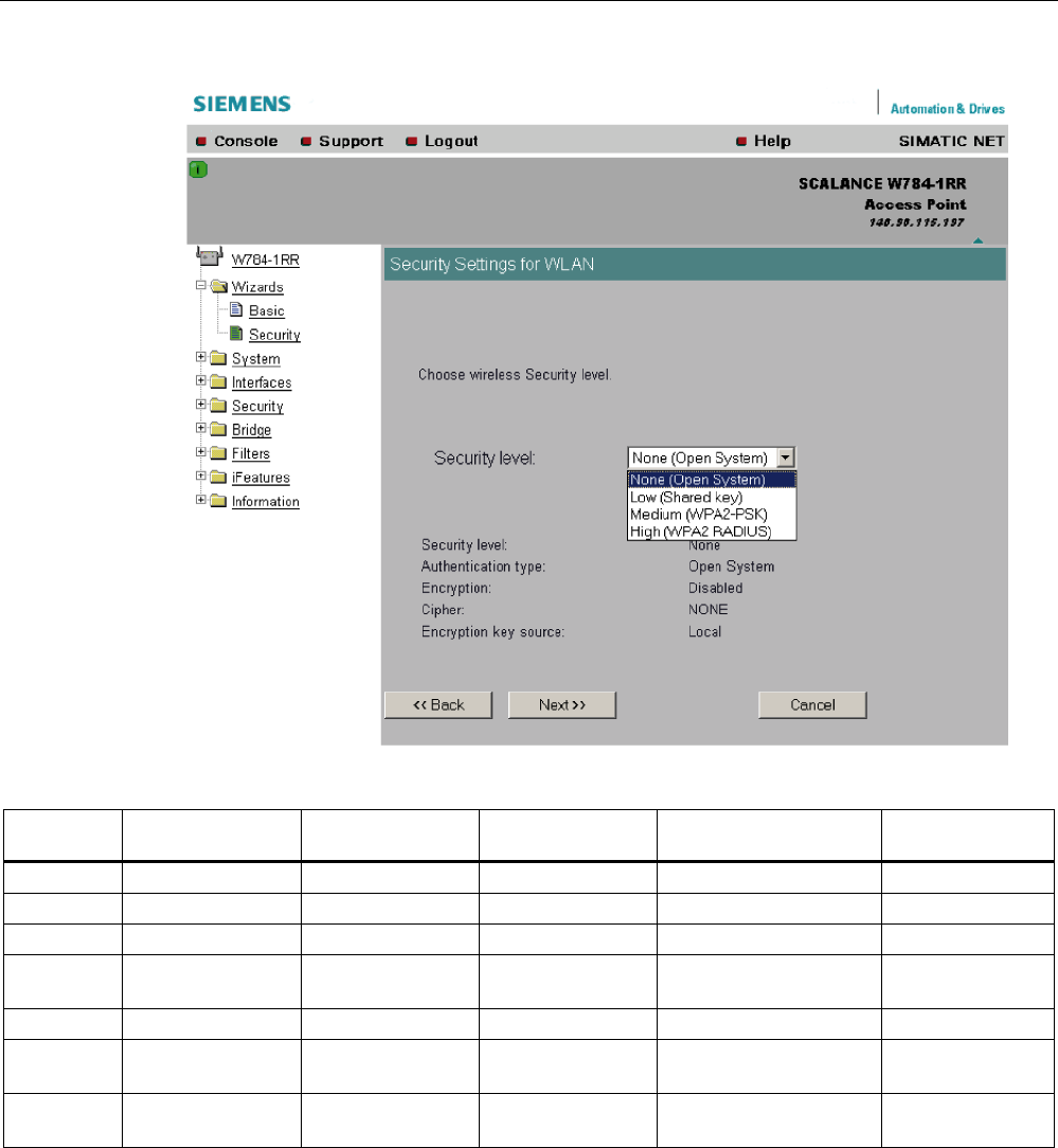
Configuration / project engineering
5.5 Security Wizard
SCALANCE W786-xPRO
Operating Instructions, Release 08/2007, C79000-G8976-C221-02 89
The following table indicates what the various security levels involve.
Visible in
wizard
Security level Authentication Encryption Type of encryption Encryption key
source
x None Open System disabled without not applicable
None Open System enabled as option WEP local
x Low Shared Key enabled WEP local
x Medium WPA2-PSK
(preshared Key)
enabled TKIP / AES / AUTO local
x High WPA2 (RADIUS) enabled TKIP / AES / AUTO Server
Medium WPA-Auto-PSK
(preshared Key)
enabled TKIP / AES / AUTO local
High WPA-Auto
(RADIUS)
enabled TKIP / AES / AUTO Server
Authentication
Authentication basically means that some form of identification is required. Authentication
therefore protects the network from unwanted access. In the "Security Level" box, you can
choose between the following types of authentication:
● None (Open System)
There is no authentication. Encryption with a fixed (unchanging) key can be selected as
an option. To do this, define a key in the "Keys" menu. 5 or 13 ASCII or 10 or 26
hexadecimal characters specify a weaker key (40/104 bits). 16 ASCII or 32 hexadecimal

Configuration / project engineering
5.5 Security Wizard
SCALANCE W786-xPRO
90 Operating Instructions, Release 08/2007, C79000-G8976-C221-02
characters, on the other hand, define a strong key (128 bits). Then select "Encryption" in
the "Basic WLAN" menu.
● Low (Shared Key)
In Shared Key authentication, a fixed key is stored on the client and access point. This is
then used for authentication and encryption. In this case, you will have to store a WEP
key after selecting "Low (Shared Key)".
● Medium (WPA2-PSK)
WPA2-PSK is based on the WPA2 standard, WPA authentication, but operates without a
RADIUS server. Instead of this, a key (pass phrase) is stored on every client and access
point and this is used for authentication and further encryption. AES or TKIP is used as
the encryption method, AES represents the standard method.
● High (WPA2)
WPA2 (Wi-Fi Protected Access 2) is a further development of WPA and implements the
functions of the IEEE 802.11i security standard. WPA2 uses the additional encryption
protocol CCMP with preauthentication that allows fast roaming in mobile ad hoc
networks. A client can log on in advance at several access points so that the normal
authentication can be omitted.
A RADIUS server is used to authenticate the client with an access point. The client logs
on at a RADIUS server based on a certificate (EAP-TLS) or a combination of user name
and password (EAP-PEAP or EAP-TTLS / internal authentication method MSCHAPv2).
As an option, the RADIUS server then identifies itself to the client using a certificate.
Following successful authentication, the client and RADIUS server generate key material
that is used for data encryption. AES or TKIP is used as the encryption method, AES
represents the standard method.
● Medium with WPA compatibility (WPA-Auto-PSK)
Select the "Medium" security level and check the "WPA compatibility"
box so that an access point can process both "WPA-PSK" authentication as well as
"WPA2-PSK". This is necessary when the access point communicates with different
clients, some using "WPA-PSK" and others "WPA2-PSK". The same encryption method
must be set on the clients.
● High with WPA compatibility (WPA-Auto)
Select the "High" security level and check the "WPA compatibility"
box so that an access point can process both "WPA" authentication as well as "WPA2".
This is necessary when the access point communicates with different clients, some using
"WPA" and others "WPA2". The same encryption method must be set on the clients.
Encryption
Encryption protects the transferred data from eavesdropping and corruption. You can only
disable encryption in the "Encryption" check box if you have selected "Open System" for
authentication in the "Basic WLAN" menu. All other security methods include both
authentication and encryption. Various schemes are used for encryption:
● WEP (Wired Equivalent Privacy)
A weak, symmetrical stream encryption method with only 40- or 104-bit long keys based
on the RC4 algorithm (Ron’s Code 4).
● TKIP (Temporal Key Integrity Protocol)
A symmetrical stream encryption method with the RC4 algorithm (Ron’s Code 4). In
contrast to the weak WEP encryption, TKIP uses changing keys derived from a main key.
TKIP can also recognize corrupted packets.
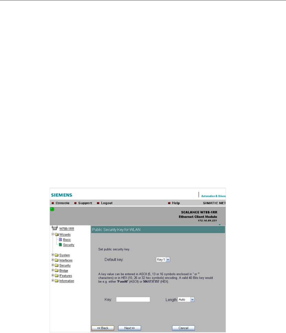
Configuration / project engineering
5.5 Security Wizard
SCALANCE W786-xPRO
Operating Instructions, Release 08/2007, C79000-G8976-C221-02 91
● AES (Advanced Encryption Standard)
Strong symmetrical block encryption method based on the Rijndael algorithm that further
improves the functions of TKIP.
● AUTO
TKIP or AES is used depending on the capability of the other station.
Encryption key source
The encryption key source indicates whether the key is configured locally and fixed (local) or
whether it is negotiated by a higher protocol and an authentication server (server).
Security Level for WLAN
drop-down list box
Select a security level that is supported by all clients. The content of the next page depends
on the selected security level. If you select the security level "None", there is no following
page since neither encryption nor authentication will be used.
5.5.7 Settings for the Low security level
Default key
drop-down list box
Select the key you want to specify.
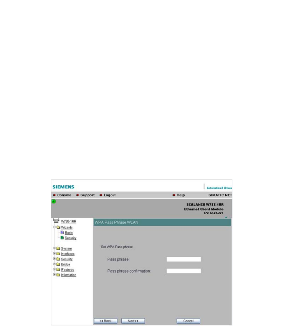
Configuration / project engineering
5.5 Security Wizard
SCALANCE W786-xPRO
92 Operating Instructions, Release 08/2007, C79000-G8976-C221-02
Key
input box
Enter the character string for the key here. The key can be entered as ASCII characters or
alternatively as hexadecimal digits (0 – F). If the key was entered in ASCII format, this is later
displayed in quotes.
Length
drop-down list box
Select the key length you want to use here. If the length of the string in the Key input box is
longer or shorter than the selected key length, an error message is displayed. The following
key lengths are possible:
● 40 bits (5 ASCII characters or 10 hexadecimal numbers)
● 104 bits (13 ASCII characters or 26 hexadecimal numbers)
● 128 bits (16 ASCII characters or 32 hexadecimal numbers)
With the "AUTO" setting, the maximum key length is also 128 bits.
5.5.8 Settings for the Medium security level
Pass phrase
input box
Here, you enter a WPA2 key. The key can be 8 to 63 ASCII characters or exactly 64
hexadecimal characters long. This initialization key must be known on both the client and the
SCALANCE W78x and is entered by the user at both ends.
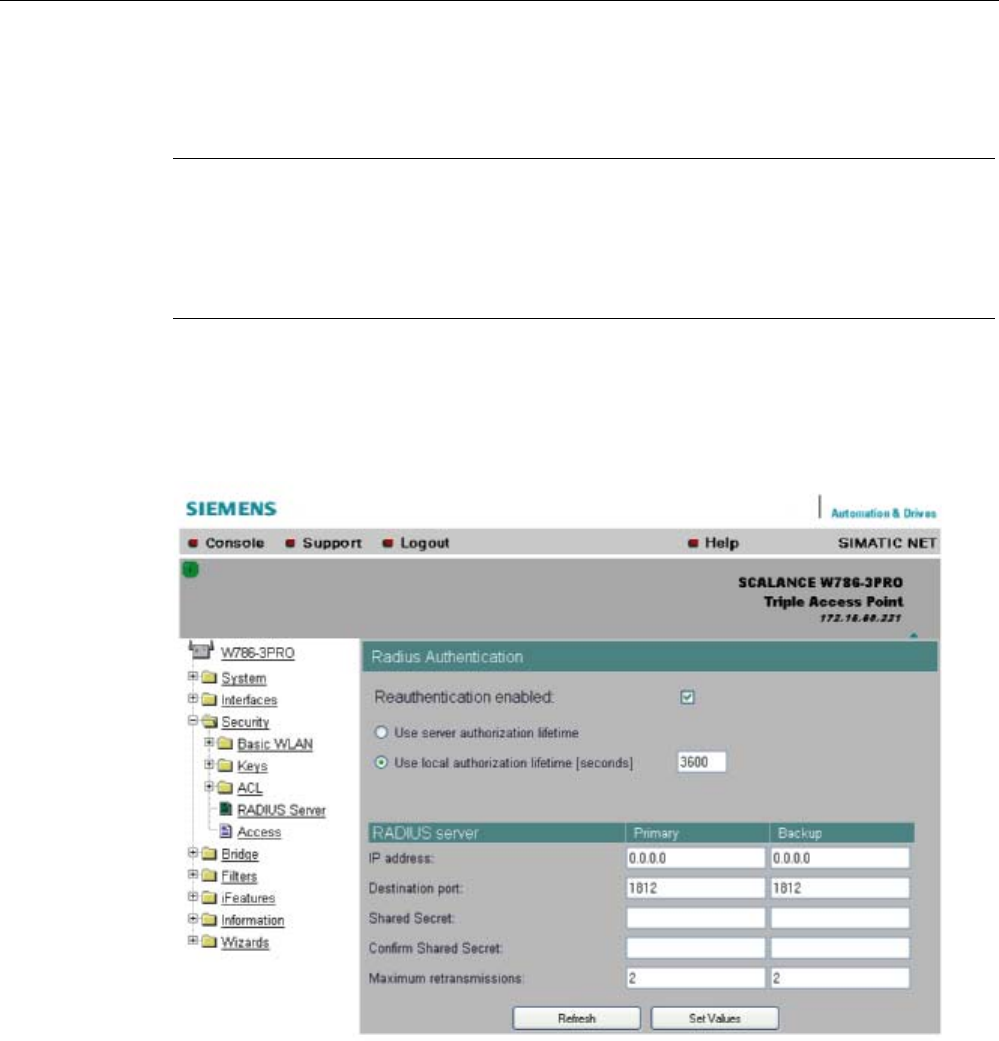
Configuration / project engineering
5.5 Security Wizard
SCALANCE W786-xPRO
Operating Instructions, Release 08/2007, C79000-G8976-C221-02 93
Pass phrase confirmation
input box
Here, you confirm the entered WPA2 key.
Note
The key can be 8 to 63 ASCII characters or exactly 64 hexadecimal characters long. It
should be selected so that is complex for example consisting of random numbers, letters
(upper-/lowercase), have few repetitions and special characters). Do not use known names,
words or terms that could be guessed. If a device is lost or if the key becomes known, the
key should be changed on all devices to maintain security.
5.5.9 Settings for the High security level in access point mode
Reauthentication input box
Here, you decide whether the access point initiates a reauthentication for the clients. You
can also select who sets the time after which the clients are forced to a reauthentication. If
time management is local, enter the period of validity of the authentication in seconds. The
minimum time is 1 minute (enter 60), the maximum time is 12 hours (enter 43200). The
default is 1 hour (3,600 seconds).
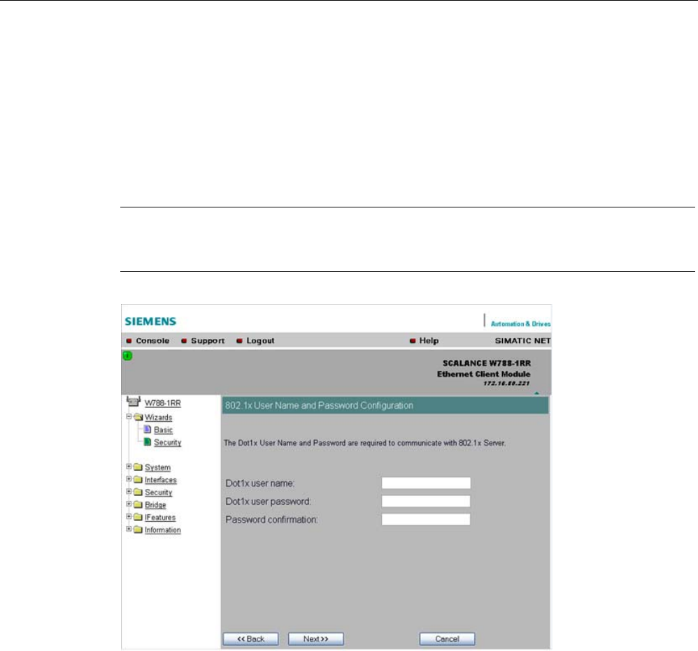
Configuration / project engineering
5.5 Security Wizard
SCALANCE W786-xPRO
94 Operating Instructions, Release 08/2007, C79000-G8976-C221-02
RADIUS Server input box
You can enter the data for two RADIUS servers; the information in the "Backup" column is
used if the server defined in the "Primary" column is not available.
5.5.10 Settings for the High security level in "Client" mode
Note
The following information applies only to SCALANCE W74x clients or SCALANCE W78x
access points operating in client mode.
Dot1x user name input box
Here, enter the user name with which you want to register over the RADIUS server.
Dot1x user password input box
Here, enter the password for the above user name. The client logs on with the RADIUS
server using this combination when a logon with a certificate was not possible.
Password confirmation input box
Confirm the password here.
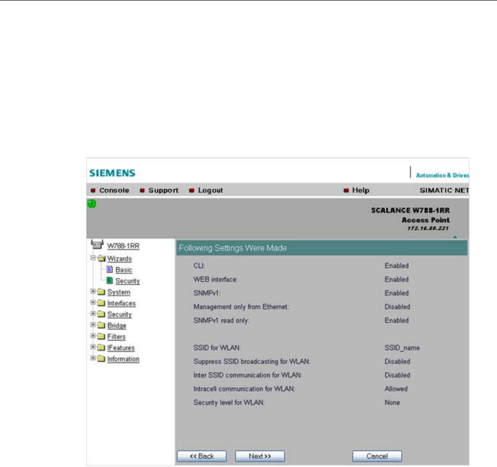
Configuration / project engineering
5.5 Security Wizard
SCALANCE W786-xPRO
Operating Instructions, Release 08/2007, C79000-G8976-C221-02 95
5.5.11 Overview of the selected security settings for an access point
Settings after working through the Security Wizard
This page contains an overview of the selected security settings. If you want to change a
setting, you can click the "Back" button to return to a previous page where you can enter a
different value or make a different selection. This page shows less information in client
mode.
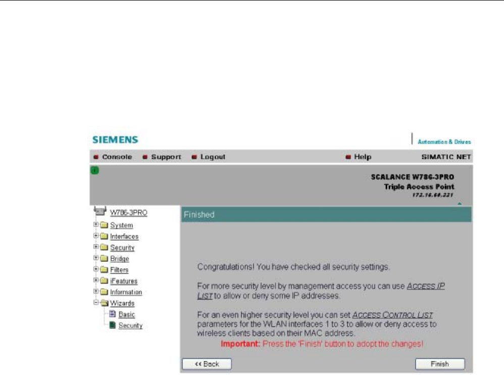
Configuration / project engineering
5.5 Security Wizard
SCALANCE W786-xPRO
96 Operating Instructions, Release 08/2007, C79000-G8976-C221-02
5.5.12 Exiting the Security Wizard
Further security settings
The last page of the wizard indicates other security measures that you can take.
Finish
button
Click the Finish button to apply the data and exit the wizard. Your settings only take effect
after you have restarted (System > Restart menu).

Configuration / project engineering
5.6 Configuration with Web Based Management
SCALANCE W786-xPRO
Operating Instructions, Release 08/2007, C79000-G8976-C221-02 97
5.6 Configuration with Web Based Management
5.6.1 General information on Web Based Management
Navigation bar
You will find the following links in the upper menu bar of Web Based Management (WBM):
● Console
This link opens a console window in which you can enter CLI commands.
● Support
When you click this link, you open a SIEMENS AG support page in the Internet.
● Logout
Close the current Web Based Management session by clicking on this link. The logon
dialog is then displayed again.
● Help
Clicking on this link opens the online help of Web Based Management in a separate
browser window.
Updating the Display with Refresh
Web Based Management pages that display current parameters have a "Refresh" button at
the lower edge of the page. Click this button to request up-to-date information from the
device for the current page.
Saving entries with Set Values
Pages in which you can make configuration settings have a "Set Value" button at the lower
edge. Click this button to save the configuration data you have entered on the device.
Creating entries with NEW
Pages in which you can create lists have the "New" button at the lower edge. Click this
button to create a new entry in the list.
Resetting a counter with Reset Statistics
With this button, you can reset the relevant counters.
Note on Login User
If you log on as user, you will only have restricted use of WEB and Telnet. Since you only
have read access, some commands do not exist in Telnet and some areas cannot be
selected.
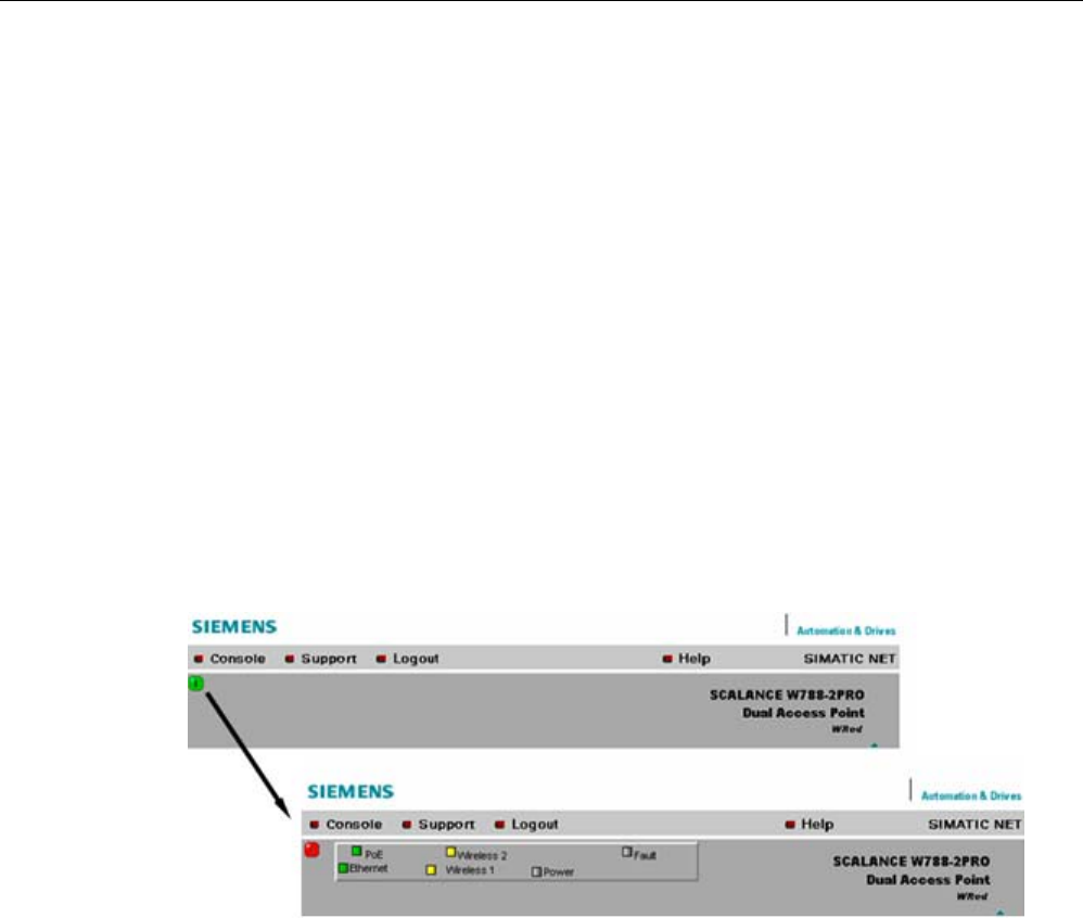
Configuration / project engineering
5.6 Configuration with Web Based Management
SCALANCE W786-xPRO
98 Operating Instructions, Release 08/2007, C79000-G8976-C221-02
Required experience
To be able to use the information in this chapter effectively, you should have a thorough
knowledge of network technology and WLANs.
5.6.2 The LED simulation of Web Based Management
Display of the operating state
The SCALANCE W-700 has one or more LEDs that provide information on the operating
state of the device. Depending on its location, direct access to the SCALANCE W-700 may
not always be possible. Web Based Management therefore displays simulated LEDs.
Activating the simulation
There is an HTML-based simulation of the LED status. Click on the green icon below the
Console link to activate the simulation.
Figure 5-1 Example: LED display of a SCALANCE W788-2PRO. Other device variants have a
different LED display.
5.6.3 The System menu
5.6.3.1 System Information menu command
Mode and locale setting
On this page, you make several basic settings for the SCALANCE W-700, for example, the
country and mode (access point or client).

Configuration / project engineering
5.6 Configuration with Web Based Management
SCALANCE W786-xPRO
Operating Instructions, Release 08/2007, C79000-G8976-C221-02 99
Changing the mode of access points
When the mode changes from access point mode to client mode and back, all the
parameters are cleared except:
● IP address
● Subnet mask
● Gateway address
● SSID (only in access point mode)
● IP address of the default router
● DHCP flag
● System name
● System location
● System contact
● Device mode
● Country code
● User and Admin passwords
The "Current system time" output box informs you about the system time. The "System up
time" output box informs you about the time that has elapsed since the last restart.
Reading out the country list
In the address field of the Internet browser, enter
https://<IP address of the SCALANCE W-700>/countrylist.log
and confirm with "Enter".
After logging in, you then obtain the country list with the following headers:
------------------------------------------------------------------
COUNTRY | MODE | CH | MHz | PWR(EIRP) | USAGE
------------------------------------------------------------------
The table lists the permitted wireless modes and channels along with the corresponding
channel frequencies for every possible country setting. The PWR(EIRP) rubric contains the
permitted limit values for the transmit power, measured at the antenna. The limit values
relate to the transmit power of the access point and the gain of the antenna being used.
Note
In the version for USA, you cannot select a country. The frequency bands for this country are
already preset.

Configuration / project engineering
5.6 Configuration with Web Based Management
SCALANCE W786-xPRO
100 Operating Instructions, Release 08/2007, C79000-G8976-C221-02
5.6.3.2 IP Settings menu command
Configuration
Here, you decide whether you will use a DHCP server or whether you want to assign a fixed
IP address to the SCALANCE W-700. You can also set the IP address of a router and the
default TTL. The TTL (time to live) parameter specifies the maximum number of routers
passed through by a data packet before it is discarded.
Note
If you use a Radius server for authentication, this must the accessible over the management
VLAN.
See also
CLI\SYSTEM\IP menu command (Page 176)
5.6.3.3 Services menu command
Configuration
Here, you select the services with which access to the device will be possible. If, for
example, the "SNMP Enabled" check box is not selected, neither write nor read access is
possible using the SNMP protocol (v1,v2c,v3). If the SNMP protocol is not permitted, it is not
possible to send SNMP traps.
To improve security, you should only enable the services that you actually use.
NOTICE
Over SNMP, it is possible to disable all services and to allow read access only over SNMP.
Following this, no further configuration of the device is possible.
If you only want to enable secure access over HTTPS when configuring the device,
select the "HTTPS only" check box.
If you want to enable the response of the device to Ping signals, select the "Ping enabled"
check box.
With the integrated SSH server, you have secure access to the CLI. In contrast to Telnet, the
entire communication including user authentication is encrypted.
Notes on WEB Enabled in the WEB interface
The check box for the "WEB Enabled" entry is selected and inactive because configuration
with Web Based Management is no longer possible without the option of access with HTTP.

Configuration / project engineering
5.6 Configuration with Web Based Management
SCALANCE W786-xPRO
Operating Instructions, Release 08/2007, C79000-G8976-C221-02 101
If you want to deactivate the option of configuration with Web Based Management, you can
do this in the Security Wizard over Telnet and SNMP. Settings made using the Security
Wizard only take effect after a restart on the device.
See also
CLI\SYSTEM\SERVICES menu command (Page 177)
5.6.3.4 Restart menu command
Restart
button
Click this button to restart the device. During a restart, the device is reinitialized, the internal
firmware is reloaded, and the device runs a self-test. The learned entries in the address table
are deleted. You can leave the browser window open while the device restarts.
Restore Memory Defaults
button
Click this button to reset the configuration. The following parameters (protected defaults) are
not reset:
● IP address
● Subnet mask
● Gateway address
● SSID
● IP address of the default router
● DHCP flag
● System name
● System location
● System contact
● Device mode
● Country code
There is no automatic restart. This allows you to enter data using Web Based Management
before the restart. The changes take effect only after a restart.
If you are logged on as user, the "Restore Memory Defaults" button is not visible.
Restore Factory Defaults and restart
button
Click on this button to restore the factory configuration settings. The protected defaults (see
above) are also reset. The C-PLUG is reinitialized and formatted if it exists. An automatic
restart is triggered.

Configuration / project engineering
5.6 Configuration with Web Based Management
SCALANCE W786-xPRO
102 Operating Instructions, Release 08/2007, C79000-G8976-C221-02
Note
By resetting all the defaults, the IP address is also lost. The device can then only be
accessed using the Primary Setup Tool unless the IP address is obtained over DHCP.
If you are logged on as user, the "Restore Factory Defaults" button is not visible.
See also
CLI\SYSTEM\RESTARTS menu command (Page 178)
5.6.3.5 Event Config menu command
System events of the device
On this page, you specify how the device reacts to system events. You can configure the
reaction of the SCALANCE W-700 to the following events:
● Starting the device
● Change in the Ethernet status Link up / Link down
● Error when a user logs in
● Change in the power supply of the device (evaluating this event only makes sense when
there is a redundant power supply).
● Change in the error status (error LED)
Additional system events for access points
If you use a SCALANCE W78x in access point mode, you can configure additional system
events:
● Events associated with a client logging on and off
● IP-Alive state change (application-specific connection monitoring)
● Link Check state change (device-specific connection monitoring)
● Events related to bandwidth reservation iQoS
● Detection of access points on own or an overlapping wireless channel
● Topology changes in Rapid Spanning Tree
● Events related to iPCF with the device variants SCALANCE W78x-xRR
● Events in conjunction with the Forced Roaming on IP down function
● Change in the WDS connection status Link up / Link down
With the device models that have more than one WLAN interface, the status of a redundant
connection (redundant, not redundant, interrupted) is also a system event.

Configuration / project engineering
5.6 Configuration with Web Based Management
SCALANCE W786-xPRO
Operating Instructions, Release 08/2007, C79000-G8976-C221-02 103
Reaction to system events
The following alternatives are available when the device reacts to a system event:
● The device sends an E-mail.
● The device sends an SNMP trap.
● The device writes an entry in the log file.
● The device indicates an error (the error LED lights up).
By selecting the appropriate check boxes, you specify which events trigger which reactions
on the device. With the check box in the "Functions enabled" row, you enable or disable the
sending of E-mails or triggering of SNMP traps.
5.6.3.6 E-mail Config menu command
Sender and recipient of an E-mail
Here, you specify who the device sends an E-mail to as a reaction to configured events. You
can also enter a sender. This allows you to recognize which device is involved and sent the
E-mail. If you do not make an entry in the "From" box, the device uses the following sender:
SCALANCE_W@<IP address>
See also
CLI\SYSTEM\EMAIL menu command (Page 181)
5.6.3.7 SNMP Config menu command
Configuration
Select the check boxes of the entries according to the SNMP functionality you want to use.
SNMP version 3 allows permissions to be assigned and protocol level, authentication, and
encryption. You specify groups and users in the Groups and Users submenus. You can also
make entries there if the SNMPv3 enabled check box is not selected, however the entries
are not applied.
NOTICE
When using SNMP version 3, you should disable SNMP V1 and V2c because the security
settings of SNMP V3 can be bypassed by access over SNMP V1 or V2c.
Trap
submenu
Here, you enter the IP addresses of up to 10 trap receivers. The device sends a trap to all
the addresses you enter if their Enable trap check boxes are selected.

Configuration / project engineering
5.6 Configuration with Web Based Management
SCALANCE W786-xPRO
104 Operating Instructions, Release 08/2007, C79000-G8976-C221-02
Note
During a warm or cold restart with a wireless connection ( AP client, WDS, or WRED), there
is no guarantee that the recipient can be reached at the time when the trap is sent. This
leads to a loss of the message.
Groups
submenu
This page displays the SNMPv3 groups. You can create a new group by clicking the "New"
button and specifying the group name, the security level, and the write or read permissions.
You can delete a group by selecting the check box in the "Del" column and clicking the "Set
Values" button. If members are already entered in the group, you cannot delete the group
nor is it possible to change the security level of the group.
There are three SNMPv3 security levels:
Security level Special features Comment
None No authentication, no encryption.
Auth/No Priv Authentication with the MD5 or
SHA algorithm, no encryption.
To display the members of the group, you
must enter the authentication password
(maximum of 63 characters).
Auth/Priv Authentication with the MD5 or
SHA algorithm, encryption with the
DES3 algorithm.
To display the members of the group, you
must enter the authentication password
(maximum of 63 characters).
Users
submenu
This page displays the SNMPv3 users. You can create a new user by clicking the "New"
button and specifying the user name and the group to which the user will belong. If
necessary, you must also enter the passwords for the authentication and for the encryption.
You can delete a user by selecting the check box in the "Del" column and clicking the "Set
Values" button.
See also
CLI\SYSTEM\SNMP menu command (Page 181)
CLI\SYSTEM\SNMP\GROUP menu command (Page 182)
CLI\SYSTEM\SNMP\USER menu command (Page 183)
CLI\SYSTEM\SNMP\TRAP menu command (Page 184)
5.6.3.8 SSyslog menu command
Syslog according to RFC 3164 is used for transferring short, unencrypted text messages
over UDP in the IP network. This requires a standard Syslog server.
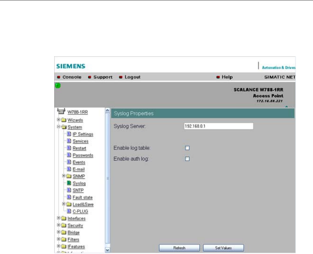
Configuration / project engineering
5.6 Configuration with Web Based Management
SCALANCE W786-xPRO
Operating Instructions, Release 08/2007, C79000-G8976-C221-02 105
Syslog Configuration with the SCALANCE W-700
The parameters used for the Syslog protocol are displayed and set in the System -> Syslog
menu:
The meaning of the parameters is as follows:
Syslog Server input box
The server address decides the IP address to which the Syslog messages are sent. If no IP
address is entered in this box, no Syslog messages are sent. If the Syslog server is not in
the same network as the SCALANCE W, an automatic attempt is made to establish a
connection over the default gateway.
log table check box
This check box decides whether all entries made in the log table are also sent as Syslog
messages.
auth log check box
This check box decides whether all entries made in the authentication log are also sent as
Syslog messages.

Configuration / project engineering
5.6 Configuration with Web Based Management
SCALANCE W786-xPRO
106 Operating Instructions, Release 08/2007, C79000-G8976-C221-02
See also
CLI\SYSTEM\SYSLOG menu command (Page 184)
5.6.3.9 SNTP Config menu command
Time-of-day synchronization in the network
SNTP is the acronym for Simple Network Time Protocol. A server uses this protocol to
provide a uniform time throughout the entire network. Clients can synchronize themselves
with this time.
If you enter the IP address of an SNTP server in the "SNTP server" text box and select the
time zone of the SCALANCE W-700 in the "Time zone offset" list box, the SCALANCE W-
700 uses the time information of this server. The SCALANCE W-700 adopts this time
information without any further conversion relating to daylight-saving or standard time.
In the "Update interval" text box, you enter the cycle time in seconds after which the
SCALANCE W-700 calls up the time information from the SNTP server. With the "Refresh
SNTP" button, you can synchronize with the SNTP server regardless of the selected update
time.
See also
CLI\SYSTEM\SNTP menu command (Page 185)
5.6.3.10 Fault State menu command
Information on errors/faults
This page displays information on faults/errors that have occurred. You can delete this
information if you click the "Remove Fault State" button.
See also
CLI\SYSTEM\FAULT menu command (Page 186)
5.6.3.11 Load & Save menu command
Saving and loading device data
Clicking the Load & Save menu command first opens a page with the current firmware
version. The "HTTP" and "TFTP" submenus allow you to save device data in external files or
to transfer data from external files to the device. If the device is operated with a C-PLUG, the
data from the loaded configuration file is stored on the C-PLUG. As long as the C-PLUG is
inserted, the device works with the configuration on the C-PLUG.
You can save the following device data in external files:
● The configuration data of the device

Configuration / project engineering
5.6 Configuration with Web Based Management
SCALANCE W786-xPRO
Operating Instructions, Release 08/2007, C79000-G8976-C221-02 107
● the content of the log table
● The firmware of the device
● The client certificate (only for clients and access points in client mode)
● The server certificate (only for clients and access points in client mode)
You can transfer the following data from external files to the device:
● The configuration data of the device
● The firmware of the device
● The client certificate (only for clients and access points in client mode)
● The server certificate (only for clients and access points in client mode)
For information on certificates, please refer to the "System Manual Basics of Industrial
Wireless LAN".
Note
When you download the configuration data to the device, it is restarted so that the new data
is adopted correctly. The restart takes place automatically during the loading of HTTP and
TFTP. The device can no longer be reached using the old IP address if the downloaded
configuration data contains a new IP address.
Note
For SCALANCE W788-xPRO/RR and W74x-1PRO/RR only
As of firmware version V3.0, the file with the configuration data of the AP also includes the
following information
• Version of the configuration file
• Firmware version with which this configuration file was created
• Order number (MLFB) of the device with which the configuration file was created
It is essential that the configuration on the C-PLUG was generated with a firmware version ≤
the firmware version on the destination device.
Example:
Configuration files created with a device with firmware V2.4 or older can be loaded without
problems on devices with firmware version V3.0 (or V3.2 on the W786-xPRO and V3.3 on
the W784-1xx/W74x-1). Configuration files generated with a device with firmware version
V3.0 (or 3.2 or 3.3), cannot, however, be loaded on devices with firmware version V2.4 or
older.
Reusing configuration data
Saving and reading in configuration data reduces the effort if several devices have the same
configuration and when IP addresses are obtained over DHCP. Save the configuration data
on a PC after you have configured a SCALANCE W-700. Download this file to all other

Configuration / project engineering
5.6 Configuration with Web Based Management
SCALANCE W786-xPRO
108 Operating Instructions, Release 08/2007, C79000-G8976-C221-02
devices you want to configure. If necessary, you may need to assign an IP address to these
devices first using the Primary Setup Tool.
How to load or save data over HTTPS
1. To load or save configuration data or the firmware, enter the name of the file from which
the data will be taken and in which the data will be saved in the relevant input box.
As an alternative, you can also use a file selection dialog that opens after you click the
"Browse..." button.
2. Start the save function by clicking the Save button. Start the load from file function by
clicking the "Load" button.
How to load or save data over TFTP
1. Enter the IP address of the TFTP server in the TFTP Server IP input box.
2. Enter the port of the TFTP server in the Port text box if the default value does not meet
your requirements.
3. Click the Set Values button before you enter any further information for saving the data.
4. Specify the name of the file (maximum 32 characters) from which the data will be taken or
where the data will be saved in the relevant input box for the configuration data or
firmware.
5. Start the save function by clicking the Save button. Start the load from file function by
clicking the Load button.
Configuration package
If security certificates for the client and/or server are installed on a client, when the
configuration is saved, the client provides the option of saving the configuration file with the
certificates as a configuration package. With the aid of the configuration package, clients can
be replicated simply; in other words, identical settings AND certificates are transferred to the
clients in one step. Just as when you download the configuration file, this is followed by a
restart. No special measures are necessary when downloading the configuration because
the SCALANCE W-700 automatically recognizes the type of configuration file.
See also
CLI\SYSTEM\LOADSAVE menu command (Page 186)
5.6.3.12 C-PLUG menu command
Information on the content of the C-PLUG
This menu command provides you with detailed information on the C-PLUG. You can also
format the C-PLUG or provide it with new content. As soon as the device is started with a C-
PLUG inserted, the SCALANCE W starts up with the configuration data on the C-PLUG.
Changes to parameters are stored on the C-PLUG and displayed over the Web and CLI.
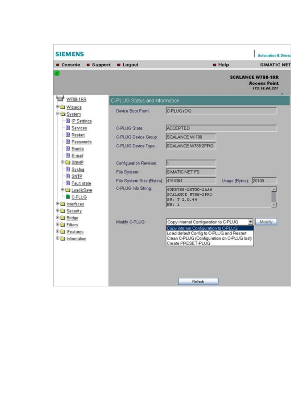
Configuration / project engineering
5.6 Configuration with Web Based Management
SCALANCE W786-xPRO
Operating Instructions, Release 08/2007, C79000-G8976-C221-02 109
The data in the memory of the device only becomes accessible when the device restarts
without a C-PLUG using the <Restart without C-PLUG> function.
Note
In terms of the C-PLUG, the SCALANCE W-700 devices work in two modes:
• Without C-PLUG
The device stores the configuration in internal memory. This mode is active when no C-
PLUG is inserted.
• With C-PLUG
The configuration stored on the C-PLUG is displayed over the user interfaces. In this
mode, the internal memory is neither read nor written. If changes are made to the
configuration, the device stores the configuration directly on the C-PLUG. This mode is
active when no C-PLUG is inserted. As soon as the device is started with a C-PLUG
inserted, the SCALANCE W-700 starts up with the configuration data on the C-PLUG.

Configuration / project engineering
5.6 Configuration with Web Based Management
SCALANCE W786-xPRO
110 Operating Instructions, Release 08/2007, C79000-G8976-C221-02
C-PLUG State
input box
This displays the status of the C-PLUG. The following are possible:
● ACCEPTED
There is a C-PLUG with a valid and matching content inserted in the device.
● NOT ACCEPTED
No C-PLUG or C-PLUG inserted but invalid or incompatible content. The status is also
displayed when the C-PLUG was formatted during operation.
● NOT ACCEPTED, HEADER CRC ERROR
A C-PLUG with bad content is inserted.
● NOT PRESENT
There is no C-PLUG inserted in the device.
C-PLUG Device Group
input box
Indicates the SIMATIC NET product line that used the C-PLUG previously.
C-PLUG Device Type input box
Indicates the device type within the product line that used the C-PLUG previously.
Configuration Revision
input box
The version of the configuration structure. This information relates to the configuration
options supported by the device and has nothing to do with the concrete hardware
configuration. This revision information does not therefore change if you add or remove
modules or extenders, it can, however, change if you update the firmware.
File System
input box
Displays the type of file system on the C-PLUG.
File System Size
input box
Displays the maximum storage capacity of the file system on the C-PLUG.
File System Usage
input box
DDisplays the memory utilization of the file system of the C-PLUG.
C-PLUG Info String
input box
Here, you will see all the additional information about the device that used the C-PLUG
previously, for example, order number, type designation, and the versions of the hardware
and software.
Modify C-PLUG drop-down list box, Modify button
You can only make settings in this box if you are logged on as "Admin". Here, you decide
how you want to change the content of the C-PLUG. The following alternatives are possible:
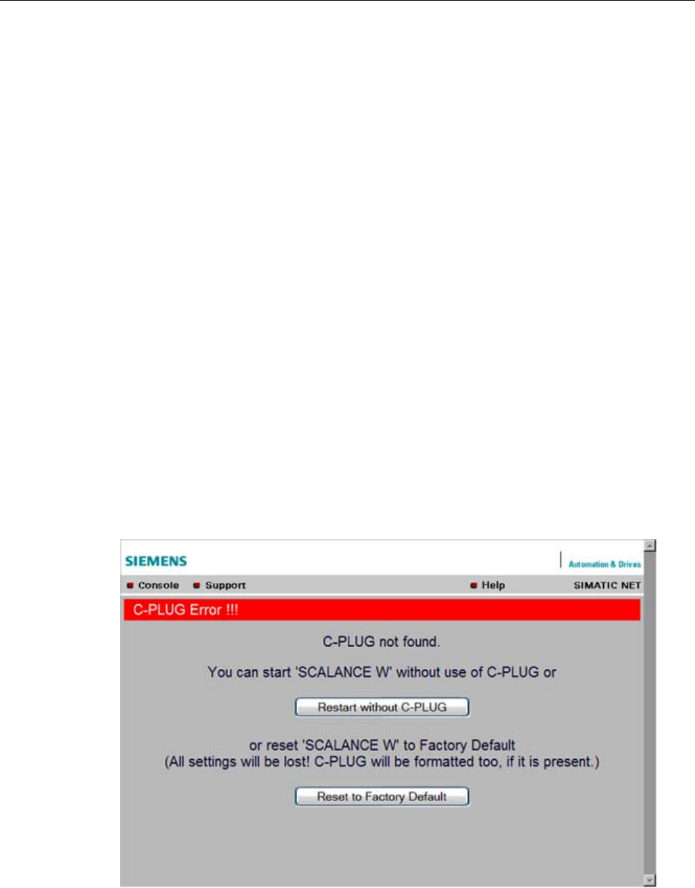
Configuration / project engineering
5.6 Configuration with Web Based Management
SCALANCE W786-xPRO
Operating Instructions, Release 08/2007, C79000-G8976-C221-02 111
● Copy internal Configuration to C-PLUG and Restart
The configuration in the internal flash memory of the SCALANCE W700 is copied to the
C-PLUG; this is followed by a restart.
This function is required in the following important use case: The device has started up
with a C-PLUG containing a bad configuration or a configuration different from the device.
If you have not yet made any configuration changes after starting up the device, you can
use this function to overwrite the content of the C-PLUG with the original device
configuration from memory.
● Load default Configuration to C-PLUG and Restart
A configuration with all the factory default values is stored on the C-PLUG. This is
followed by a restart in which the device starts up with these default values.
● Clean C-PLUG (Low Level Format, Configuration lost)
Deletes all data on the C-PLUG and starts a low-level formatting function. There is no
automatic restart.
● Create PRESET PLUG
Writes configuration data to a PRESET PLUG. For detailed information on this topic, refer
to the section "Configuring with the PRESET-PLUG".
After making your selection, start the function by clicking the "Modify" button.
C-PLUG error message
If the device detects a C-PLUG error during startup, a message is displayed by Web Based
Management. C-PLUG errors can have two causes:
● The C-PLUG contains bad data or data for a different device type.
● There is no C-PLUG in the device although a C-PLUG was present prior to the last
shutdown of the device.

Configuration / project engineering
5.6 Configuration with Web Based Management
SCALANCE W786-xPRO
112 Operating Instructions, Release 08/2007, C79000-G8976-C221-02
See also
CLI\SYSTEM\CPLUG menu command (Page 188)
5.6.4 The Interfaces menu
5.6.4.1 Interfaces menu command
Introduction
The SCALANCE W-700 has one Ethernet interface and one or more WLAN interfaces that
can be configured separately. In the pages of this menu, you can configure both the wired
Ethernet interface and the WLAN interface.
With the menu command Interfaces > WLAN1…3 > Virtual AP count in the Access Point
mode, you can also configure up to eight virtual access points (VAP0 … VAP7) per wireless
interface.
Note
VAPs are visible only after an AP count > 0.
5.6.4.2 Ethernet menu command
TTransmission speed and mode
For a wired Ethernet interface with an RJ-45 connector, you only specify the transmission
speed / mode parameters and the crossing over of the Ethernet connection. When you
select the Auto entry in the "Speed / Mode" drop-down list box, the device sets a suitable
speed and mode depending on the other network nodes and crosses over the Ethernet
connection.
If you select an entry other than Auto in the "Speed / Mode" drop-down list box, you must
specify the crossing over of the Ethernet connection manually with "Ethernet crossing".
Note
If you specify the mode, you must make the same settings on the partner device.
There is no parameter assignment for devices with ST duplex multimode fiber-optic
connectors. The Ethernet MAC address and the current transmission speed/mode are
displayed.
See also
CLI\INTERFACES\ETHERNET menu command (Page 189)

Configuration / project engineering
5.6 Configuration with Web Based Management
SCALANCE W786-xPRO
Operating Instructions, Release 08/2007, C79000-G8976-C221-02 113
5.6.4.3 WLAN menu command
Enabling the interface
Enable the interface by selecting "Enable Interface".
Network name (in access point mode only)
Enter the network name of the wireless network in the "SSID" input box. If you have used the
Basic Wizard, a value is already entered here.
Infrastructure / Ad-Hoc (only for clients or access points in client mode)
Select Infrastructure to connect to an access point. "Ad hoc" is used to connect clients with
each other without an access point. This is only possible when "Ad hoc" is set on all clients.
Transmission mode
Specify the transmission mode in the "Wireless Mode" list box. If you have used the Basic
Wizard, a value is already entered here.
Note
IEEE 802.11h transmission
It is not possible to select the 802.11h protocol in all country settings. It is specified by the
configuration of Country code on the System page.
If the 802.11h protocol is selected, after applying the configuration with Set Values, the
comment (DFS is active for this country code) appears behind the Enable Interface check
box.
With the automatically enabled Dynamic Frequency Selection function (DFS), prior to
communication, the access point checks whether the configured or selected channel (see
Auto Channel Select) is free of signals from a primary user (for example radar).
If signals of a primary user are found on the configured or selected channel, the access point
follows the procedure outlined below:
• Auto channel select = enabled
With automatic channel select, the access point changes to a different channel and
repeats the availability check for this channel.
• "Auto channel select" = disabled
If there is a fixed configured channel, the access point changes to the configured
alternative channel and repeats the availability check for this channel. If a primary user (for
example radar) is discovered on the alternative channel, a further channel is selected at
random.
Communication with clients is started only when no primary user has been discovered on the
selected channel for one minute.
When operating PNIO systems with wireless standard 802.11h, make sure that no radar
signals occur in the vicinity of the system. Due to the DFS strategy in 802.11h, there is a
channel change if radar signals are detected.

Configuration / project engineering
5.6 Configuration with Web Based Management
SCALANCE W786-xPRO
114 Operating Instructions, Release 08/2007, C79000-G8976-C221-02
Outdoor AP mode (only in access point mode) / Outdoor Client mode (only for clients or access point
in client mode)
The device can be operated either in the indoor or outdoor mode. In indoor mode, all the
country-dependent permitted channels and transmit power settings are available for
operation in a building. In outdoor mode, the selection of country-dependent channels and
the transmit power for operation are restricted for outdoor use. You enable this mode by
selecting "Outdoor AP mode" or "Outdoor Client mode".
Channel Selection
On clients or access points in client mode, you can only set a channel in ad hod mode.
For access points, you have the following options: Select the "Auto Channel Select" check
box if you want the access point to search for a free channel itself. If you want to specify a
specific channel, make sure that "Auto Channel Select" is not selected. You can specify a
suitable channel in the "Radio Channel" drop-down list box.
IEEE 802.11h transmission:
If you have selected the 802.11h protocol for transmission in access point mode and "Auto
Channel Select" is not selected, the "Alt. radio channel" input box is displayed below
"Radio channel". Here, you can select the alternative channel in case signals of a primary
user are found on the main channel.
Make sure that the alternative channel is not being used by other access points.
In the IEEE 802.11h transmission mode, it is not practical to select the WDS mode. In WDS
mode, all access points must use the same channel. If a signal from a primary user is
detected by an access point, the channel is changed automatically and the existing
connection is then terminated.
MAC address of the client (only for clients or access points in client mode)
A MAC address must be specified for the devices connected to the Ethernet port of the client
before it can be reached. This MAC address is used by the client for wireless communication
with the access point. This can be done automatically by the client adopting the MAC
address of the first frame that it receives over the Ethernet interface. If this is required, "Auto
find Adopt MAC" must be selected.
As long as the client is waiting for an Ethernet frame, it registers with the access point using
its own MAC address. As soon as the first Ethernet frame is received, the client deregisters
from the access point and immediately registers again with the MAC address from the
Ethernet frame. If there is now a link-down on the Ethernet port, the client deregisters from
the access point and registers again with its own MAC address.
If several devices are connected to the client, you should not select this setting.
You also have the option of specifying the MAC address of the connected device manually.
To use this option, select "Set 'Adopt MAC' manually" and enter the MAC address of the
device connected to the client in the "Adopt MAC" input box.
To be able to address an entire network of devices downstream from the client, "Adopt own
MAC" must be selected. In this case, only layer 3 connections (TCP/IP) are possible. This is,
however, not possible with the SCALANCE W744-1PRO and SCALANCE W744-1.
If up to eight MAC addresses need to be served downstream from the client, the "Layer 2
Tunneling" setting must be selected for the client.

Configuration / project engineering
5.6 Configuration with Web Based Management
SCALANCE W786-xPRO
Operating Instructions, Release 08/2007, C79000-G8976-C221-02 115
Note
The layer 2 tunneling functionality is supported by SCALANCE W-700 access points as of
firmware version V3.1. This setting meets the requirements of industrial applications in which
MAC address-based communication with several devices downstream from the client is
required. Clients with this setting cannot connect to standard Wi-Fi devices and SCALANCE
W-700 access points with firmware V3.0 or older.
Virtual AP count (only in access point mode)
If you want to configure virtual access points (VAPs) on this AP, set the number of virtual
access points using the "Virtual AP count" drop-down list box. If "Virtual AP count = 0 and
VLAN/Prio Tag" are disabled, no VAPs are created.
You can define up to a maximum of 8 VAPs. The settings of VAP0 are made directly in
"Interfaces/WLAN", the settings for VAP1...7 can be found in the
"Interfaces/WLAN/VAP1...7" submenus.
By using virtual access points, various SSIDs (maximum of 8 per WLAN interface) can be
configured with different security settings. You can assign each virtual AP to a particular
VLAN.
Set Values
Apply the configuration by clicking "Set Values".
If you have configured virtual access points ("Virtual AP count > 0"), in "access point" mode,
you will be requested to run a restart on the SCALANCE W78x after clicking "Set Values".
5.6.4.4 Advanced menu command
Configuring transmission characteristics
On this page, you can specify details of the transmission characteristics. You only need to
adapt the parameters on this page if the device cannot be used as it is intended with the
default settings.
Transmit power
In the Transmit Power list box, you can specify the output power of the device. It may be
necessary to reduce the transmit power when using antennas to avoid exceeding the
maximum legal transmit power. Reducing the transmit power effectively reduces cell size.

Configuration / project engineering
5.6 Configuration with Web Based Management
SCALANCE W786-xPRO
116 Operating Instructions, Release 08/2007, C79000-G8976-C221-02
Beacons
Beacons are packets that are sent cyclically by an access point to inform clients of its
existence. In the "Beacon Interval" input box, you specify the interval at which the device
sends beacons.
In access point mode only
The "Data Beacon Rate DTIM" parameter (Delivery Traffic Indication Map) specifies how
often the access point sends broadcast and multicast packets over the wireless interface. If
you enter 1 in this box, the access point transmits broadcast and multicast packets directly
after each beacon (recommended setting for normal network environments). The value 5
would mean that the access point collects the broadcast and multicast packets and sends
them after every fifth beacon.
Increasing this value allows a longer sleep mode for the clients but means a greater delay for
broadcast and multicast packets.
Note
The lowest basic rate in the INTERFACE\WLAN\DATARATES menu is used as the "Beacon
Rate". The higher the data rate of the beacon, the shorter the range of the beacon.
RTS/CTS
RTS/CTS (Request To Send/Clear To Send) is a method for avoiding collisions based on the
exchange of status information before sending the actual data (hidden node problem). To
minimize network load resulting from the additional protocol exchange, this method is used
only when a packet size that you select with the "RTS/CTS Threshold" is exceeded.
Fragmentation
The "Fragmentation Length Threshold" parameter specifies the maximum package size
transferred on the wireless link. Large packets are divided up into small packets prior to
transmission and then reassembled into the original size after they have been received. This
can be beneficial if the transmission quality is poor because larger packets are more difficult
to transmit. However fragmentation into smaller packets means a poorer throughput.
Repetitions
There are two situations in which packets are repeated. The hardware repetition is
performed by the WLAN chip itself when it tries to repeat an unacknowledged packet
immediately. The number of attempted repetitions is specified with the "HW Retry number"
parameter.
If all hardware repetitions were unsuccessful, the packet is withdrawn and all other packets
in the buffer are sent first. Following this, transmission of the packet is attempted again. The
number of such repetitions is specified with the "SW Retry number" parameter.
The software repetition mechanism can be enabled or disabled with "Use SW Retry".
Shortened preamble with 802.11b
The 802.11b standard allows the use of shortened preambles in the wireless transmission of
data packets. This increases the amount of user data.

Configuration / project engineering
5.6 Configuration with Web Based Management
SCALANCE W786-xPRO
Operating Instructions, Release 08/2007, C79000-G8976-C221-02 117
Antenna Gain
The "Antenna Gain" parameter describes the antenna gain in dBi of an antenna connected
to a SCALANCE W-700.
You can set values for the following parameters:
● "Antenna Type"
● "Antenna Gain"
● "Antenna cable length (in meters)"
If "Antenna Type" is set to "User Defined", you can enter any value in the "Antenna Gain"
box for the antenna gain. Otherwise, the preconfigured value of the selected "Antenna Type"
is displayed. In the "Antenna cable length (in meters)" box, you enter the length of the
connecting cable between the device and the antenna.
It is necessary to set a specific value to make sure that the regulations of the national
authorities are adhered to. The national authorities, for example, specify all usable channels,
the corresponding maximum transmit power and other conditions of use. You will find more
detailed information on the regulations in your country using the countrylist.log.
Based on the settings for antenna gain and transmit power, the SCALANCE W-700
automatically selects the permitted channels. Under some circumstances, there may be
fewer permitted channels available for antennas with a higher antenna gain than for
antennas with a lower antenna gain.
Note
If you select "User defined", you have the option of entering dBi values as integers for the
antenna gain in the range from 0 through 30 dBi. Please remember to take the losses of the
antenna connecting cable into account.
NOTICE
The correct antenna setting is mandatory for operation complying with the approvals. A
false antenna gain entry can lead to legal proceedings!
Antennas
The "Antenna Mode" list box specifies the use of antennas.
● The Diversity setting takes the better of the two antennas for the data transmission. For
each WLAN interface, both antennas must be connected. Both antennas should also be
of the same type and they should also illuminate approximately the same space. If an
access point is operated with the diversity setting and the two antennas span different
cells, this can have negative effects.
● With the setting "Tx on A, Rx on B", antenna A is used to send and antenna B to receive.
● With the setting "Tx on B, Rx on A" antenna B is used to send and antenna A to receive.
With the settings "Diversity, Tx on A, Rx on B" and "Tx on B, Rx on A", both antennas must
be connected on each WLAN interface. If only one antenna is connected, the connected

Configuration / project engineering
5.6 Configuration with Web Based Management
SCALANCE W786-xPRO
118 Operating Instructions, Release 08/2007, C79000-G8976-C221-02
antenna must be set permanently. The second antenna socket must also have a 50 Ω
terminator fitted.
Note
For information on the location of the antenna sockets, refer to the section "Connectors for
external antennas".
Scan for access points (only for clients and access points in client mode)
While the client is connected to an access point, it scans for other access points in the
background with which it can connect when necessary. There are three modes for scanning
access points that can be selected in the "Background scan mode" drop-down list box.
If you set "Disable", there is no scan for access points while the client is connected.
If you set "Scan if Idle", there is a scan for access points when no data transfer takes place
for a certain time.
If you set "Scan Always", access points are scanned continuously.
The "Background scan interval" parameter specifies the interval at which further access
points are scanned.
To optimize the scanning for further access points, you can specify channels for the client on
which other access points can be found. To allow this, the "Background Scan Ch.Select"
check box must be set and the channels of the other access points entered in the
"Background Scan Channels" text box. Enter the channels separated by blanks.
If the client finds a better access point, it attempts to connect to it. Before it changes, the new
access point must be better than the current access point by a certain value. The threshold
at which the client changes to the new access point can be specified with the "Roaming
threshold" parameter.
Roaming when there is no Ethernet interface (access point mode only)
If the wired Ethernet interface is no longer available (cable break, connector removed), a
client connected over the wireless network is not aware of this. The access point can then
force the logged-on WLAN clients to roam by deactivating its WLAN interface. The client
then attempts to log on at a different access point. You enable this feature by selecting the
"Force roaming if link down on the Ethernet interface" check box.
Enable WMM
With wireless multimedia, multimedia frames are transferred according to the IEEE 802.11e
standard with a higher priority.
Select the Enable WMM option if you want frames evaluated according to their priority and
sent prioritized over the WLAN interface.
According to the Wi-Fi standard, prioritized frames are classified as follows:
Access Category Description 802.1d Tags
WMM voice priority Highest priority
Allows multiple concurrent VoIP calls, with low latency
and toll voice quality
7, 6

Configuration / project engineering
5.6 Configuration with Web Based Management
SCALANCE W786-xPRO
Operating Instructions, Release 08/2007, C79000-G8976-C221-02 119
Access Category Description 802.1d Tags
WMM Video priority Prioritize video traffic above other data traffic.
One 802.11g or 802.11a channel can support 3-4
SDTV streams or 1 HDTV streams.
5, 4
WMM best effort priority Traffic from legacy devices, or traffic from applications
or devices that lack QoS capabilities.
Traffic less sensitive to latency, but affected by long
delays, such as Internet surfing.
0, 3
WMM background priority Low priority traffic (file downloads, print jobs) that
does not have strict latency and throughput
requirements.
2, 1
5.6.4.5 SSID List menu command
Note
The "SSID List" submenu is only available for clients and access points in client mode. You
can specify the mode in the "System" menu.
How the client connects to the network
With this menu command, you can specify how the device connects to a network as client:
● If the Connect to ANY SSID check box is selected, the device in client mode attempts to
connect to the network with the best transmission quality and with suitable security
settings. If the "Suppress SSID broadcasting" setting is made for an access point, the
client cannot log on there with the ANY SSID.
● If this check box is not selected, the client attempts to connect to the network from the
SSID list that has the best transmission quality.
An SSID is absolutely necessary in ad hoc networks and iPCF. The maximum number of
SSIDs in the SSID list is restricted to 32.
See also
CLI\INTERFACES\WLAN1\SSID (or \WLAN2\SSID or \WLAN3\SSID) menu command
(Page 194)
5.6.4.6 Advanced G menu command
Properties of the 802.11g standard
The IEEE 802.11g is upwards compatible with IEEE 802.11b, both use the 2.4 GHz band. In
contrast to 802.11b that specifies data rates up to 11 Mbps, 802.11g provides for data rates
up to 54 Mbps. The 802.11g standard also uses the OFDM modulation scheme. This

Configuration / project engineering
5.6 Configuration with Web Based Management
SCALANCE W786-xPRO
120 Operating Instructions, Release 08/2007, C79000-G8976-C221-02
technology divides a data packet into several smaller packets that are transmitted at the
same time at different frequencies.
Special options for 802.11g settings
The options you can set in the Advanced G submenu relate to the way in which
management and control data (RTS/CTS frames, beacons) are sent in the 802.11g mode.
You can also specify that the SCALANCE W-700 only supports 802.11g-compatible devices.
Handling 802.11b clients
The access point automatically detects whether 802.11b clients exist in the area. To avoid
802.11g packets colliding with 802.11b packets, the access point can use the RTS/CTS
method.
Using RTS/CTS (in access point mode only)
With the "802.11g CTS Mode" drop-down list box, you specify the use of RTS/CTS:
None Do not use RTS/CTS.
Always Always use RTS/CTS with 802.11g packets.
Auto Only use RTS/CTS when there are 802.11b clients in area.
You can set the data rate for RTS/CTS frames in the "802.11g CTS Rate" drop-down list
box.
With the "802.11g CTS Type" drop-down list box, you specify whether only a CTS or
RTS/CTS is sent.
802.11g enhancements
With the "802.11g Short Slot Time" parameter, you specify whether or not the short slot time
is used. This short slot time should be supported by all newer clients.
With the "802.11g Only Mode" parameter, you can specify that only 802.11g clients can log
on at the access point and also that only 802.11g rates are permitted (in access point mode
only). In this mode, only the OFDM modulation method is used. This prevents 802.11b
devices from registering. If 802.11g Only mode is disabled, both 802.11b devices and
802.11.g devices can register with the access point.
5.6.4.7 Data Rates menu command
Note
The "Data Rates" submenu is available only in access point mode.
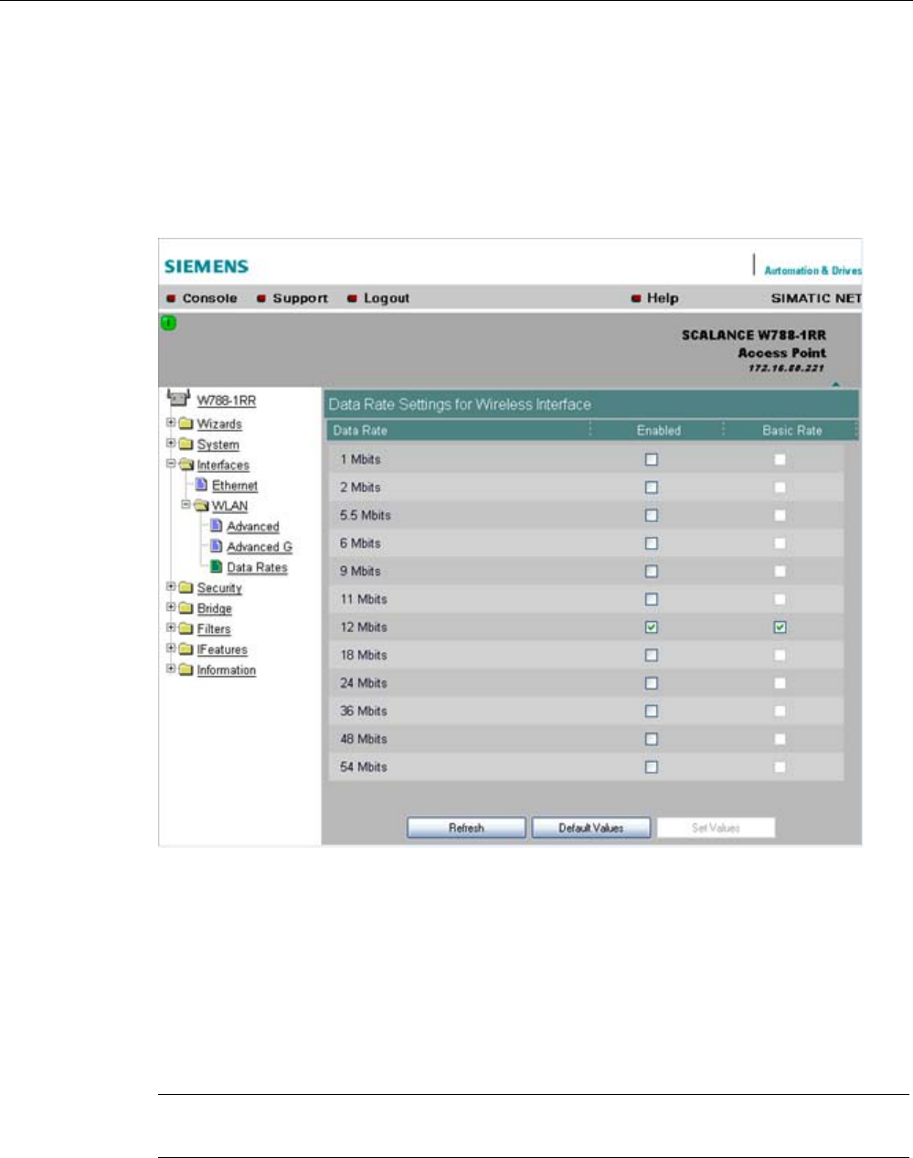
Configuration / project engineering
5.6 Configuration with Web Based Management
SCALANCE W786-xPRO
Operating Instructions, Release 08/2007, C79000-G8976-C221-02 121
Variable setting of the transmission rates
From the table showing all available data rates for the current WLAN mode (802.11b, g, a
etc.), you can select any combination of these data rates. The access point will then use only
the selected transmission rates for communication with the clients.
The "Basic Rate" parameter specifies that a client must be capable of this data rate to be
able to connect to the access point.
See also
CLI\INTERFACES\WLAN1\DATARATES (or \WLAN2\DATARATES or
\WLAN3\DATARATES) menu command (Page 196)
5.6.4.8 VAP menu command
Note
The "VAP" submenu is available only in access point mode.

Configuration / project engineering
5.6 Configuration with Web Based Management
SCALANCE W786-xPRO
122 Operating Instructions, Release 08/2007, C79000-G8976-C221-02
Description
You can only complete the pages of the virtual access points VAP1...VAP7 if you have
configured virtual access points ("Virtual AP count > 0") at the higher level "Interfaces >
WLAN".
On this page, you can assign a separate SSID to the virtual access points; in other words,
the access point operates in multiple SSID mode.
SSID
Enter the SSID of the VLAN here.
Make sure that you also store the SSID of this VLAN in the configuration of the client that
you assign to this VLAN.
Note
You can configure separate security settings for each virtual access point (see section "Basic
Wireless menu command")
The security settings of the VAPs must meet those of the relevant VLANs.
See also
CLI\INTERFACES\WLAN1\VAP1..7 (or \WLAN2\VAP1..7 or \WLAN3\VAP1..7) menu
command (Page 197)
5.6.5 The Security menu
5.6.5.1 Security menu command
Introduction
In this menu, you configure the security settings with which you want to operate your device.
Apart from selecting the authentication and encryption scheme, this also includes the
decision as to whether or not an external Radius server is used and whether access is
restricted based on MAC addresses (ACL).
See also
CLI\SECURITY menu command (Page 197)

Configuration / project engineering
5.6 Configuration with Web Based Management
SCALANCE W786-xPRO
Operating Instructions, Release 08/2007, C79000-G8976-C221-02 123
5.6.5.2 Basic Wireless menu command
Authentication
Authentication basically means that some form of identification is required. Authentication
therefore protects the network from unwanted access. In the "Security Level" box, you can
choose between the following types of authentication:
● Open System
There is no authentication. Encryption with a fixed (unchanging) key can be selected as
an option. To do this, define a key in the "Keys" menu. 5 or 13 ASCII or 10 or 26
hexadecimal characters specify a weaker key (40/104 bits). 16 ASCII or 32 hexadecimal
characters, on the other hand, define a strong key (128 bits). Then select "Encryption" in
the "Basic WLAN" menu.
Note
With the following devices in iPCF mode, only this setting is possible:
• SCALANCE W788-xRR in client mode
• SCALANCE W784-xRR in client mode
• SCALANCE W747-1
• SCALANCE W747-1RR
• IWLAN/PB-Link PNIO
● Shared Key
In Shared Key authentication, a fixed key is stored on the client and access point. This is
then used for authentication and encryption. In this case, you will have to store a WEP
key after selecting "Low (Shared Key)".
Note
Only in access point mode:
When using an open system with encryption or shared key in conjunction with ACL lists,
note the information in Section "ACL menu command".
● WPA2-PSK
WPA2-PSK is based on the WPA2 standard, WPA authentication, however, operates
without a RADIUS server. Instead of this, a key (pass phrase) is stored on every client
and access point and this is used for authentication and further encryption. AES or TKIP
is used as the encryption method, AES represents the standard method.
Note
The key can be 8 to 63 ASCII characters or exactly 64 hexadecimal characters long. It
should be selected so that is complex, (for example consisting of random numbers,
letters (upper-/lowercase), have few repetitions and special characters). Do not use
known names, words and terms that could be guessed. If a device is lost or if the key
becomes known, the key should be changed on all devices to maintain security.
● WPA2
WPA2 (Wi-Fi Protected Access 2) is a further development of WPA and implements the
functions of the IEEE 802.11i security standard. WPA2 uses the additional encryption
protocol CCMP with preauthentication that allows fast roaming in mobile ad hoc
networks. A client can log on in advance at several access points so that the normal

Configuration / project engineering
5.6 Configuration with Web Based Management
SCALANCE W786-xPRO
124 Operating Instructions, Release 08/2007, C79000-G8976-C221-02
authentication can be omitted.
A RADIUS server is used to authenticate the client with an access point. The client logs
on at a RADIUS server based on a certificate (EAP-TLS) or a combination of user name
and password (EAP-PEAP or EAP-TTLS / internal authentication method MSCHAPv2).
As an option, the RADIUS server then identifies itself to the client using a certificate.
Following successful authentication, the client and RADIUS server generate key material
that is used for data encryption. AES or TKIP is used as the encryption method, AES
represents the standard method.
● WPA-Auto-PSK
Setting with which an access point can process both the "WPA-PSK" as well as the
"WPA2-PSK" type of authentication. This is necessary when the access point
communicates with different clients, some using "WPA-PSK" and others "WPA2-PSK".
The same encryption method must be set on the clients.
● WPA-Auto
Setting with which an access point can process both the "WPA" as well as the "WPA2"
type of authentication. This is necessary when the access point communicates with
different clients, some using "WPA" and others "WPA2". The same encryption method
must be set on the clients.
Encryption
Encryption protects the transferred data from eavesdropping and corruption. You can only
disable encryption if you have selected "Open System" for authentication. All other security
methods include both authentication and encryption.
Encryption methods
If you have selected Open System including encryption or "Shared Key" for authentication,
you will need to define a key in the "Keys" menu (see section "Keys menu command").
● WEP (Wired Equivalent Privacy)
A weak, symmetrical stream encryption method with only 40- or 104-bit long keys based
on the RC4 algorithm (Ron’s Code 4).
If you have selected WPA-PSK or WPA (RADIUS) as the authentication, the following
alternatives are available in the "Cipher" box:
● TKIP (Temporal Key Integrity Protocol)
A symmetrical stream encryption method with the RC4 algorithm (Ron’s Code 4). In
contrast to the weak WEP encryption, TKIP uses changing keys derived from a main key.
TKIP can also recognize corrupted packets.
● AES (Advanced Encryption Standard)
Strong symmetrical block encryption method based on the Rijndael algorithm that further
improves the functions of TKIP.
● AUTO
AES or TKIP is used depending on the capability of the other station.
RADIUS Authentication Method (only for clients and access points in client mode)
If a client is authenticated over an external RADIUS server, you can use the "RADIUS
authentication type" selection list to specify a method for external authentication. As default,
the "Auto" value is selected so that the client provides a RADIUS server with all supported
methods. Any other selection restricts the support by the client to this one method. This step

Configuration / project engineering
5.6 Configuration with Web Based Management
SCALANCE W786-xPRO
Operating Instructions, Release 08/2007, C79000-G8976-C221-02 125
may be necessary because some RADIUS servers do not evaluate the response of the client
completely or correctly.
The following options are available:
● EAP TLS - Extensible Authentication Protocol - Transport Layer Security. Uses
certificates for authentication
● EAP TTLS - Extensible Authentication Protocol - Tunnel Transport Layer Security. After
setting up the TLS tunnel, MS-CHAPv2 is used for internal authentication.
● PEAP - Protected Extensible Authentication Protocol. Alternative draft protocol of IETF
for EAP-TTLS
Additional Entries for WPA-PSK and WPA2-PSK
To use the WPA-PSK scheme, you must enter a string in the Pass Phrase box that is used
by the SCALANCE W74x to initialize dynamic key generation.
Suppress SSID broadcasting (only in access point mode)
With the Suppress SSID broadcasting setting, the SCALANCE W78x is only ever accessible
to clients that know its SSID. This method can be used to protect the SCALANCE W78x from
unauthorized access.
Note
Since no encryption is used for the SSID transfer, this function can only provide basic
protection against unauthorized access. The use of an authentication method (for example
WPA (RADIUS) or WPA-PSK if this is not possible) provides higher security.
You must also expect that certain end devices may have problems with access to a hidden
SSID.
Inter SSID communication check box (only in access point mode)
Selecting this check box allows communication between WLAN clients registered at different
SSIDs of an access point.
Example 1: A SCALANCE W78x-2xx or W786-3PRO was defined with different SSIDs.
Example 2: A SCALANCE W78x-1xx is used with multiple SSIDs.
Note
On a SCALANCE W78x-2xx or W786-3PRO, the Inter SSID communication function must
be enabled on all WLAN interfaces or on all VAPs to allow communication between the
clients with different SSIDs.

Configuration / project engineering
5.6 Configuration with Web Based Management
SCALANCE W786-xPRO
126 Operating Instructions, Release 08/2007, C79000-G8976-C221-02
Note
If VLANs are configured for the SSIDs, this setting can prevent communication between the
SSIDs according to the VLAN rules.
Intracell communication list box (only in access point mode)
● Intracell blocking
This setting prevents WLAN client communication within an SSID.
● Ethernet blocking
This setting prevents WLAN client communication over the Ethernet interface of the
access point.
● Disabled
This setting enables both WLAN client communication within an SSID as well as WLAN
client communication over the Ethernet interface.
Overview of the communication options (in access point mode only)
To illustrate the situation, there is an overview of the effects of the "Inter SSID
communication" and "Intracell communication" settings below.
Settings Possible communication
Inter SSID
communication
Intracell
communication
within
an SSID
with another SSID to the Ethernet
network
Enabled Allowed X X X
Enabled Intracell
blocking
X X
Enabled Ethernet
blocking
X X
Disabled Allowed X X
Disabled Intracell
blocking
X
Disabled Ethernet
blocking
X
VAP (in access point mode only)
For each virtual access point VAP1 to VAP7, you configure the following security settings
described earlier:
● Authentication
● Enable encryption
● Encryption method
● Select the default WEP key

Configuration / project engineering
5.6 Configuration with Web Based Management
SCALANCE W786-xPRO
Operating Instructions, Release 08/2007, C79000-G8976-C221-02 127
● Enter the WPA-PSK password
● Specifies the "Group Key Update Intervals" in WPA-PSK
● Enable "Suppress SSID broadcasting"
Where they apply, all other security parameters are adopted from the Security > Basic >
WLAN1 or WLAN2 or WLAN3 page.
5.6.5.3 Keys menu command
Specifying the WEP key
To allow you to enable the encryption for the Open System and Shared Key authentication
methods, you must first enter at least one key in the key table. You can choose between
several key lengths. 5 or 13 ASCII or 10 or 26 hexadecimal characters specify a weaker key
(40/104 bits). 16 ASCII or 32 hexadecimal characters, on the other hand, define a strong key
(128 bits).
You can also create keys for WDS Redundancy and ACL Private (these are not supported
by all clients for ACL).
Note
For the key, you can use characters 0x20 to 0x7e from the ASCII code. Below, there is a list
of all supported characters starting with a space:
!"#$%&'()*+,-./0123456789:;<=>?@
ABCDEFGHIJKLMNOPQRSTUVWXYZ[\]^_`
abcdefghijklmnopqrstuvwxyz{|}~
See also
CLI\SECURITY\KEYS\WLAN1 (or \WLAN2 or \WLAN3) menu command (Page 200)
5.6.5.4 ACL menu command
Note
The "ACL" menu is available only in access point mode.
Access rights for individual clients
The access control list (ACL) is and assignment of MAC addresses and access rights.
If ACL is enabled, prior to data transfer, the access point checks whether the necessary
permissions for the communication partner (identified by the MAC address) are entered in
the ACL table

Configuration / project engineering
5.6 Configuration with Web Based Management
SCALANCE W786-xPRO
128 Operating Instructions, Release 08/2007, C79000-G8976-C221-02
Note
Since no encryption is used for MAC address transfer, this function can only provide basic
protection against unauthorized access. The use of an authentication method (for example
WPA (RADIUS) or WPA-PSK if this is not possible) provides higher security.
Enabling the ACL
In Web Based Management, there is a drop-down list box for the use of ACL.
To enable ACL, set the global share to either "Enabled" or "Strict":
● Enabled
All clients entered in the ACL are handled according to the ACL entry. Clients not entered
in the ACL have access to the access point. This setting can be used to deny access by
certain clients.
● Strict
All clients entered in the ACL are handled according to the ACL entry. Clients not entered
in the ACL have no access to the access point. This setting can be used to allow access
by certain clients.
● Disabled
The access control list is not used.
Changing an entry in the ACL
Click the relevant MAC address to change the entry in the ACL. With the "Sel" check box,
you decide whether or not an ACL entry is used. The "Del" check box is used to delete an
entry from the ACL.
New entry in the ACL
Click the New button to create a new entry in the ACL. A page appears on which you can
make the necessary settings. Enter the "MAC address" of the client in the "MAC Address"
text box. You specify the access permissions of the client in the "Permission" drop-down list
box:
● Allow
The client has access to the access point.
● Deny
The client does not have access to the access point.
● Default Key
The client only has access to the access point when it uses the default key for encryption
of the data. To allow this, you must specify a valid default key for the SCALANCE W78x
(for example in the WBM "Security" menu) that is also used by the client.
● Private Key
With this setting, you can use different keys for different clients. You first create the
private keys with the "Keys" menu command. You can select one of these keys in the
"Key number" drop-down list box. The client only has access to the access point when it

Configuration / project engineering
5.6 Configuration with Web Based Management
SCALANCE W786-xPRO
Operating Instructions, Release 08/2007, C79000-G8976-C221-02 129
uses this private key. For this function, the client must support private keys.
Note
The private key set in the ACL must also be available in the key list on the client. The
client must also use this private key for communication in Security->Basic->WLAN (the
key must be set),if an open system with encryption or shared key is used.
The private key is used on this connection for the transferred unicast packets intended for
the wireless client.
All multicast and broadcast packets are transferred with the public key set on the access
point. The wireless client entered in the ACL list must therefore also enter this public key
at the same location in its key list as the access point.
Example
In its cell, an access point uses the shared key setting with a 128-bit public key (default key
1) for encryption of the data traffic.
All wireless clients that register at this access point, require this public key at position 1 in
their key list for communication.
If access for certain wireless clients is now restricted by the ACL list of the access point on
the basis of a private key, the private key must first be stored in the key list of the access
point and the appropriate wireless clients.
The next step is to enter the MAC addresses of these wireless clients in the ACL list of the
access point and to assign the private key. If it is intended that these wireless clients should
continue communication, the private key must be set on the wireless client directly under
Security->Basic->WLAN and used for the encryption. Otherwise the clients could receive
broadband or multicast packets, but no longer be addressed directly with unicast packets.
See also
CLI\SECURITY\ACL\WLAN1 (or \WLAN2 or \WLAN3) menu command (Page 201)
5.6.5.5 RADIUS Server menu command
Note
The "RADIUS" menu command is available only in access point mode.
Authentication over an external server
The concept of RADIUS is based on an external authentication server. A client can only
access the network after the access point has verified the logon data of the client with the
authentication server. Both the client and the authentication server must support the EAP
protocol (Extensive Authentication Protocol). The SCALANCE W-700 supports the external
authentication mechanisms EAP-TLS, EAP-TTLS and PEAP.

Configuration / project engineering
5.6 Configuration with Web Based Management
SCALANCE W786-xPRO
130 Operating Instructions, Release 08/2007, C79000-G8976-C221-02
See also
CLI\SECURITY\RADIUS menu command (Page 202)
5.6.5.6 Access menu command
Access permissions for IP addresses
In this menu, you specify the access permissions for IP addresses. You can specify whether
management access (SNMP, Telnet, WBM) is possible with the defined addresses:
● Management access is possible only with the defined addresses.
Or:
● Management access is possible with all IP addresses not included in the list.
Note
The defined access rights also apply to the PC used for configuration. If you have not
entered the local IP address and have set the ACL mode to "Accessed", no further
access to the SCALANCE W-700 is possible.
You should also note that the IP address of the client can change if you use DHCP
without reservation.
See also
CLI\SECURITY\ACCESS menu command (Page 203)
5.6.6 The Bridge menu
5.6.6.1 Bridge menu command
Introduction
A bridge is a network component that connects two networks. A bridge is not dependent on
the protocol; management of the data packages is based on the physical address of the
network nodes (MAC address).
The SCALANCE W-700 provides bridge functionality because it handles data exchange
between wired and wireless Ethernet. The following sections describe the functions that are
available and how you configure and use them.
Deleting aged bridge information
The SCALANCE W-700 saves the information about which MAC address can be reached
over which port in a learning table. Entries in this list are deleted automatically when there is
no further data transfer for the corresponding MAC addresses. You can decide the length of

Configuration / project engineering
5.6 Configuration with Web Based Management
SCALANCE W786-xPRO
Operating Instructions, Release 08/2007, C79000-G8976-C221-02 131
time after which addresses are deleted if no data is sent using the "Aging Time" parameter
on the start page of the "Bridge" menu.
See also
CLI\BRIDGE menu command (Page 204)
5.6.6.2 WDS menu command
Note
The WDS menu command is available only in access point mode and when iPCF is not
enabled.
Communication between access points
In normal operation, the SCALANCE W78x is used as an interface to a network and
communicates with clients. There are, however, situations in which several access points
need to communicate with each other, for example to extend wireless coverage or to set up
a wireless backbone. This mode is possible with WDS (Wireless Distributed System).
Note
For SCALANCE W788-xPRO/RR and W74x-1PRO/RR only
With the firmware update to ≥ V3.0, the SCALANCE W78x-xRR devices need to be
reconfigured if you use WDS or redundancy and use the MAC address and not the
sysName.
These functions are then based on the MAC address that changed with the introduction of
VAPs with V3.0.
Configuration
In the "MAC / sysName" column, enter the MAC address or the system name of the access
point with which you want to communicate. If you select the "Enc" check box, encryption is
used.

Configuration / project engineering
5.6 Configuration with Web Based Management
SCALANCE W786-xPRO
132 Operating Instructions, Release 08/2007, C79000-G8976-C221-02
Note
In WDS mode, the following restrictions apply:
• All access points that will communicate with each other must use the same channel.
• You can select either WEP or WPA(2)_PSK as the encryption method.
If you want to use WPA_PSK or WPA2_PSK as the encryption method, you will need to
set the WPA_PSK, WPA2_PSK or WPA/WPA2-AUTOPSK mode in the security settings
and the WPA pass phrase on the relevant interface (VAP0). If a different security level is
selected, you cannot use WPA(2)-PSK with WDS.
To activate WPA(2)-PSK, select the "WPA_PSK" entry instead of a key.
Once you have selected WPA-PSK or WPA2-PSK for a connection, all WDS connections
must be protected by at least a WEP key.
• If you want to attach a different access point from the SCALANCE W78x over WDS, you
must configure the MAC address. Detection using the "sysName" parameter does not
work in this situation.
• In the IEEE 802.11h transmission mode, it is not practical to select the WDS mode. In
WDS mode, all SCALANCE W78x devices must use the same channel. If a signal from a
primary user is detected by an access point, the channel is changed automatically and
the existing connection is then terminated.
• As soon as you use the same channel for more than one WLAN interface, you will have
to set WDS addressing using MAC addresses. Configuration with "sysName" can lead to
registering with the wrong interface and probable impairment of communication.
To enable the entry, you select the "Sel" check box.
See also
CLI\BRIDGE\WDS\WLAN1 (or \WLAN2 or \WLAN3) menu command (Page 204)

Configuration / project engineering
5.6 Configuration with Web Based Management
SCALANCE W786-xPRO
Operating Instructions, Release 08/2007, C79000-G8976-C221-02 133
5.6.6.3 VLAN menu command
Note
The "VLAN" menu command is available only in access point mode of a SCALANCE W78x.
Assignment and management of the VLAN IDs
The "Current VLAN Configuration" dialog displays a table with an overview of the configured
VLAN IDs (VID). The assignment of the configured ports of the access point is also
displayed as a member of these VLANs.
The "Name" is used to identify an entry within the current table. "Member List" displays 'U' for
untagged member of a VLANs or '–' if a port is not member of a VLAN. The sequence is
sorted from left to right in ascending order; in other words, according to the ID of the
interface (WLAN 1, WLAN 1 VAP 1, WLAN 2 VAP 2… or WLAN 1 WDS 1, WLAN 1 WDS
2...).
Entries in red, indicate members in the table, entries in black indicate the configured port
VLAN IDs.
If an interface is member of a VLAN ID, that is not the same as the port VID, frames arriving
from Ethernet with this VLAN ID are accepted. Outgoing frames, however, always have the
port VLAN ID.
Click on "VID" or "Name" to open the configuration page for VLAN IDs. With "New", you
create a new VLAN ID, with "Refresh", you can update the table.
Note
The Ethernet interface does not remove VLAN tags from outgoing frames.
If the VLAN is active, the WLAN interfaces always remove all VLAN tags from the outgoing
frames.
Member List Description
U If VID equals port VID; in other words untagged frames from WLAN are given this
VID.
U If the port is a member of the VID; in other words, tagged frames from Ethernet are
forwarded on this port.
— If the port is not a member of the VID; in other words, all the frames coming from
Ethernet are blocked / discarded with the corresponding VLAN ID. Frames containing
unconfigured VIDs and untagged frames are always blocked if the VLAN is active.
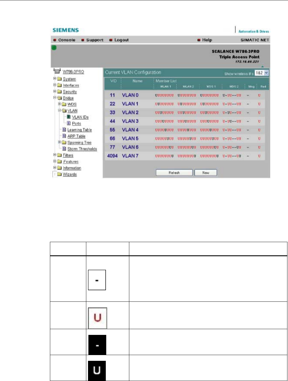
Configuration / project engineering
5.6 Configuration with Web Based Management
SCALANCE W786-xPRO
134 Operating Instructions, Release 08/2007, C79000-G8976-C221-02
VLAN ID settings
The VLAN ID box allows you to enter a new VID as long as no port is assigned explicitly as
member. Otherwise, the VID can no longer be modified.
Representati
on
Settings Description
1
Field can be edited.
If all editable boxes are displayed in this way and if the VID is not
configured as port VID, the VID is deleted when you exit this page.
Clicking on the field changes to depiction 2.
2
Field can be edited.
Clicking on the field changes to depiction 1.
3
Field cannot be edited.
Al entries for VLAN membership are being used.
4
Field cannot be edited.
VID corresponds to the port VID
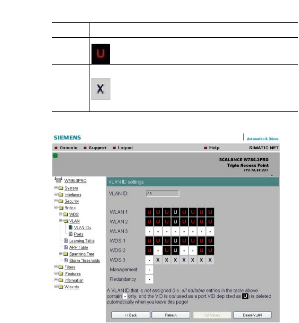
Configuration / project engineering
5.6 Configuration with Web Based Management
SCALANCE W786-xPRO
Operating Instructions, Release 08/2007, C79000-G8976-C221-02 135
Representati
on
Settings Description
5
Field cannot be edited.
Corresponding port is set to "all VIDs",
6
Field cannot be edited.
Corresponding port is not configured so no VID can be assigned.
Ports
Port: Overview of the ports in the form of a table.
"SSID": SSID for WLAN interface, no entry for WDS or management and redundancy.
"Priority": Configured priority of the port.
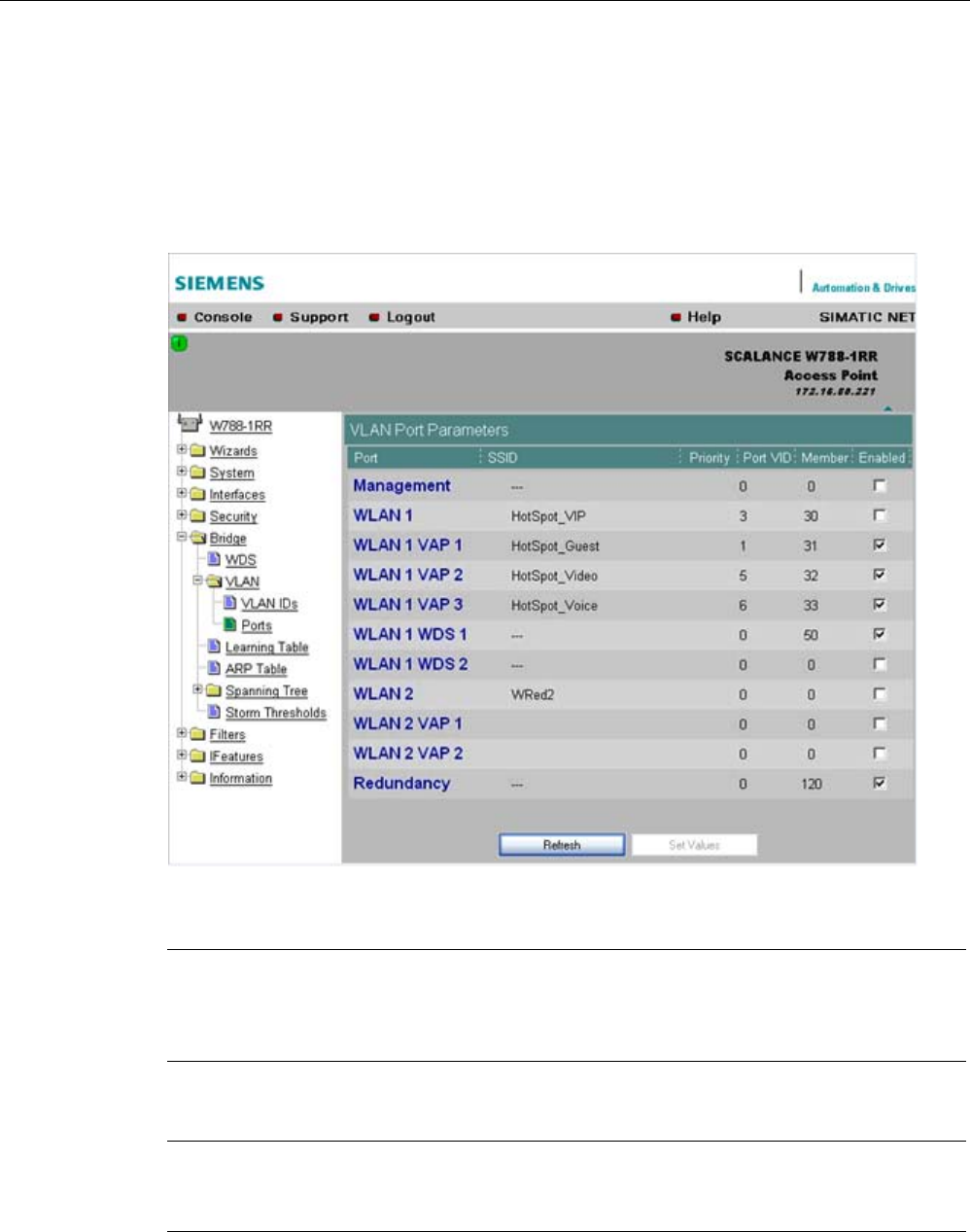
Configuration / project engineering
5.6 Configuration with Web Based Management
SCALANCE W786-xPRO
136 Operating Instructions, Release 08/2007, C79000-G8976-C221-02
"Port VID": VLAN ID directly assigned to the port.
"Member": The VLAN membership assigned to the port.
"Enabled": VLAN support can then be enabled / disabled directly.
Clicking on a port opens the VLAN Settings configuration page.
Note
If you use a Radius server for authentication, this must the accessible over the management
VLAN. Among other things, the management port also handles the functions: HTTP, HTTPS,
WBM, Telnet, SSH, Ping, DHCP, TFTP, SNMP, SNTP and Syslog.
Note
The IP and MAC-based nodes downstream from a client with enabled layer 2 tunneling
function ( L2T client) adopt the same VLAN properties as the client.
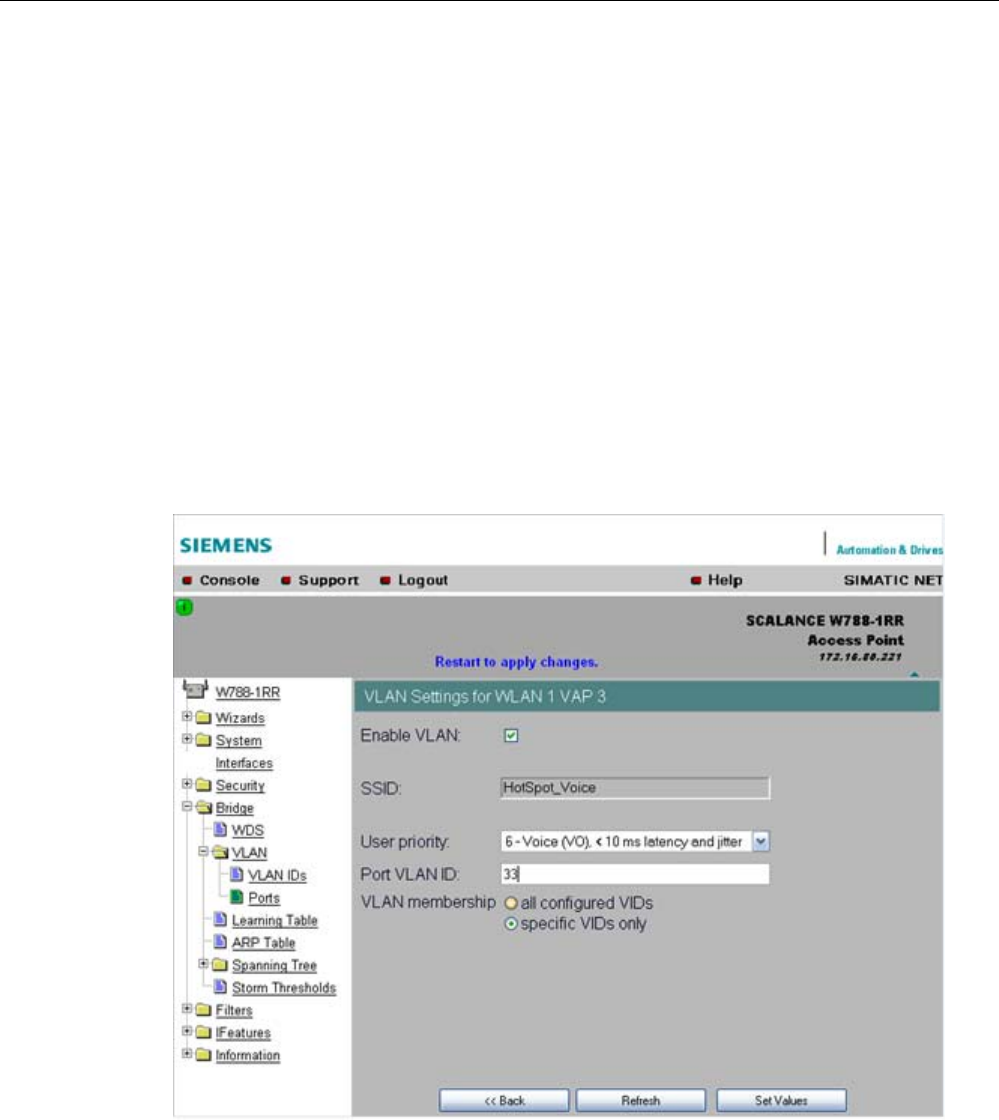
Configuration / project engineering
5.6 Configuration with Web Based Management
SCALANCE W786-xPRO
Operating Instructions, Release 08/2007, C79000-G8976-C221-02 137
Example:An L2T client is connected to the access point over the WLAN1 VAP3 interface.
WLAN1 VAP3 is a member of the VLAN ID 33 that is assigned priority 6. For the L2T port,
this means that the devices connected downstream from the L2T client and the client itself
are also members VLAN ID 33 with priority 6.
VLAN settings
"VLAN enabled": VLAN support can then be enabled / disabled directly.
"User Priority": Prioritizing the data traffic via the port. Untagged frames are given this
priority.
"Port VLAN ID": Entry of the VLAN ID.
"VLAN Membership"
"All VIDs": Automatic setting of the port as member of all configured VIDs.
"Specific VIDs only": Member of up to eight, freely assignable configured VIDs per port.
VLAN enable
Select the "VLAN enable" option if you want to enable the VLAN function. If "VLAN enable"
is selected, all frames of this VAP are given a VLAN tag.

Configuration / project engineering
5.6 Configuration with Web Based Management
SCALANCE W786-xPRO
138 Operating Instructions, Release 08/2007, C79000-G8976-C221-02
User priority
Specify the priority of the frames of this VAP with the "User priority" drop-down list box. The
priority is evaluated by the connected VLAN-compliant switches (for example,
SCALANCE X-400) of the network. The priority rises with the ascending numbers:
Note
The priority generally increases with the ascending numbers. The exception is priority 0, that
has a higher priority than priority classes 1 and 2 and has the same priority as class 3.
● "0 - Best Effort (BE)"
Normal data traffic.
● "1 - Background (BK)"
Non time-critical data traffic.
● "2 - Spare (--)"
This priority is reserved
● "3 - Excellent Effort (EE)"
Data traffic with highest priority
● "4 - Controlled Load (CL)"
● "5 - Voice (VI), < 100 ms latency and jitter"
Video/multimedia
● "6 - Voice (VO), < 10 ms latency and jitter"
Voice over IP
PNIO
● "7 - Network Control (NC)"
Internal network control frames
Default is 0 - Best Effort (BE).
Note
Both voice over IP and PNIO have priority 6.
Port VLAN ID
Here, you enter the VLAN ID (VID) of the VLAN on which the virtual access point will
communicate.
The individual VLANs are configured in the VLAN-compliant Industrial Ethernet switches (for
example SCALANCE X-400). The VID of a VLAN is in the range from 1 to 4094.
VLAN membership
Here, you specify the VLANs for which the virtual access point will be a member or which
other VLANs the port VLAN ID (VID) entered above will be assigned to.
The following alternatives in the assignment are possible:
● "all"
The VAP is member of all VLANs.

Configuration / project engineering
5.6 Configuration with Web Based Management
SCALANCE W786-xPRO
Operating Instructions, Release 08/2007, C79000-G8976-C221-02 139
● "only"
The VAP is member only of the VLANs entered below.
Here, enter the VLAN ID (VID) of up to 8 VLANs in which the VAP will be a member.
See also
CLI\BRIDGE\VLAN\VLAN_ID menu command (Page 205)
CLI\BRIDGE\VLAN\PORTS menu command (Page 206)
5.6.6.4 Learning Table menu command
Assignment of MAC address and port
The learning table contains the information about whether a MAC address can be reached
over the wired Ethernet interface or over the wireless interfaces. The SCALANCE W-700
obtains this information from the active data exchange. The learning table also contains
information on clients and on up to 8 devices connected downstream from it operating in the
layer 2 tunneling mode.
5.6.6.5 ARP Table menu command
Assignment of MAC address and IP address
The ARP protocol (Address Resolution Protocol) obtains the corresponding MAC address of
a known IP address. The page of this menu command also indicates the interface over
which an address can be reached. The last column indicates how the information was
obtained (for example "dynamic" if it was obtained during operation or "static" if it was
configured).
5.6.6.6 Spanning Tree menu command
Note
The "Spanning tree" menu command is available only when you use the SCALANCE W78x
in access point mode.
Avoiding loops on redundant connections
The spanning tree algorithm allows network structures to be created in which there are
several connections between two stations. Spanning tree prevents loops being formed in the
network by allowing only one path and deactivating the other (redundant) ports for data
traffic. If there is an interruption, the data can be sent over an alternative path. The
functionality of the spanning tree algorithm is based on the exchange of configuration and
topology change frames.

Configuration / project engineering
5.6 Configuration with Web Based Management
SCALANCE W786-xPRO
140 Operating Instructions, Release 08/2007, C79000-G8976-C221-02
Definition of the network topology using the configuration frames
Network components exchange configuration frames known as BPDUs (Bridge Protocol
Data Unit) with each other to calculate the topology. The root bridge is selected and the
network topology created using these frames. The root bridge is the bridge that controls the
spanning tree algorithm for all involved components. BPDUs also bring about the status
change of the bridge ports.
Rapid Spanning Tree
The rapid spanning tree algorithm is based on the spanning tree algorithm. This was
optimized in terms of the reconfiguration time. Typical reconfiguration times for Spanning
Tree are between 20 and 30 seconds. With rapid spanning tree, the reconfiguration times
are around 1 second. This was achieved by the following measures:
● Edge ports
A port defined as an edge port is activated after the hello time (the time between two
configuration frames). When the hello time has elapsed, the station can be certain that no
further configuration frame will arrive and that this port is an edge port. If the user wants
to avoid the hello time, spanning tree can be disabled at this port.
● Point to Point (direct communication between two neighboring stations)
By directly linking network components, a status change (reconfiguration of the ports) can
be made without any delays. A point-to-point connection can, for example, be a WDS
connection between two access points.
● Alternate port (substitute for the root port)
A substitute for the root port is configured. If the connection to the root bridge is lost, the
station can establish a connection over the alternate port without any delay by
reconfiguring.
● Filter table
In rapid spanning tree, ports affected by a reconfiguration are immediately deleted from
the filter table. With spanning tree, on the other hand, the point at which a port is deleted
is decided by the time when the port was entered in the filter table.
● Reaction to events
Rapid spanning tree reacts to events, for example an aborted connection, without delay.
There is no waiting for timers as in spanning tree.
In principle, therefore with rapid spanning tree, alternatives for many parameters are
preconfigured and certain properties of the network structure taken into account to reduce
the reconfiguration time.
(Rapid) Spanning Tree configuration
The parameters used for the (Rapid) Spanning Tree protocol are displayed in the "(Rapid)
Spanning Tree Properties" menu.
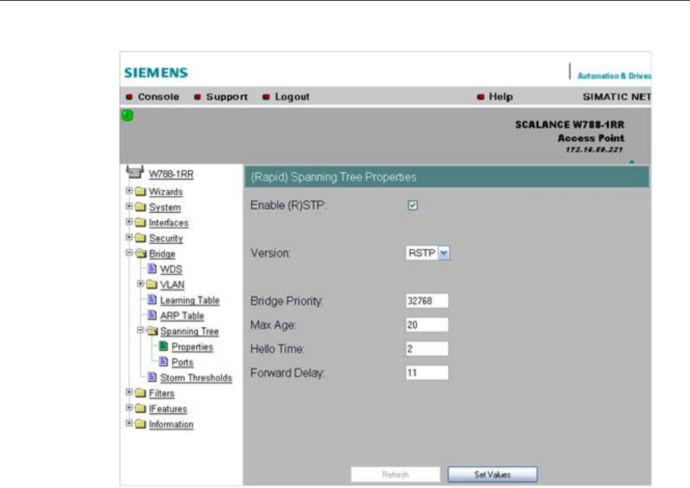
Configuration / project engineering
5.6 Configuration with Web Based Management
SCALANCE W786-xPRO
Operating Instructions, Release 08/2007, C79000-G8976-C221-02 141
If necessary, modify the following parameters to specify how the (rapid) spanning tree
algorithm operates:
● Enable (R)STP check box
Select the Enable Spanning Tree check box if you want to use the (rapid) spanning tree
algorithm. If the check mark is not set, all ports are automatically in the 'Forwarding'
status.
● Version drop-down list box
The version decides whether the Rapid Spanning Tree protocol (RSTP) is used or
whether the device is operated in compatibility mode of the Spanning Tree protocol
(STP).
● Bridge Priority input box
The identification of the most efficient connection is always related to the root bridge, a
network component that can be considered as a root element of a tree-like network
structure. With the "Bridge Priority" parameter you can influence the selection of the root
bridge.
The bridge with the highest priority (in other words, with the lowest value for this
parameter) becomes the root bridge. If several network components in a network have
the same priority, the station whose MAC address has the lowest numeric value will
become the root bridge. Both parameters, bridge priority and MAC address together form
the Bridge Identifier. Since the root bridge manages all path changes, it should be located
as centrally as possible due to the propagation time of the frames. The value for the
bridge priority is a whole multiple of 4096 with a range of values from 0 through 61440.
● Max Age input box
Max Age is the time that a bridge waits for a configuration frame (BPDU). When this time
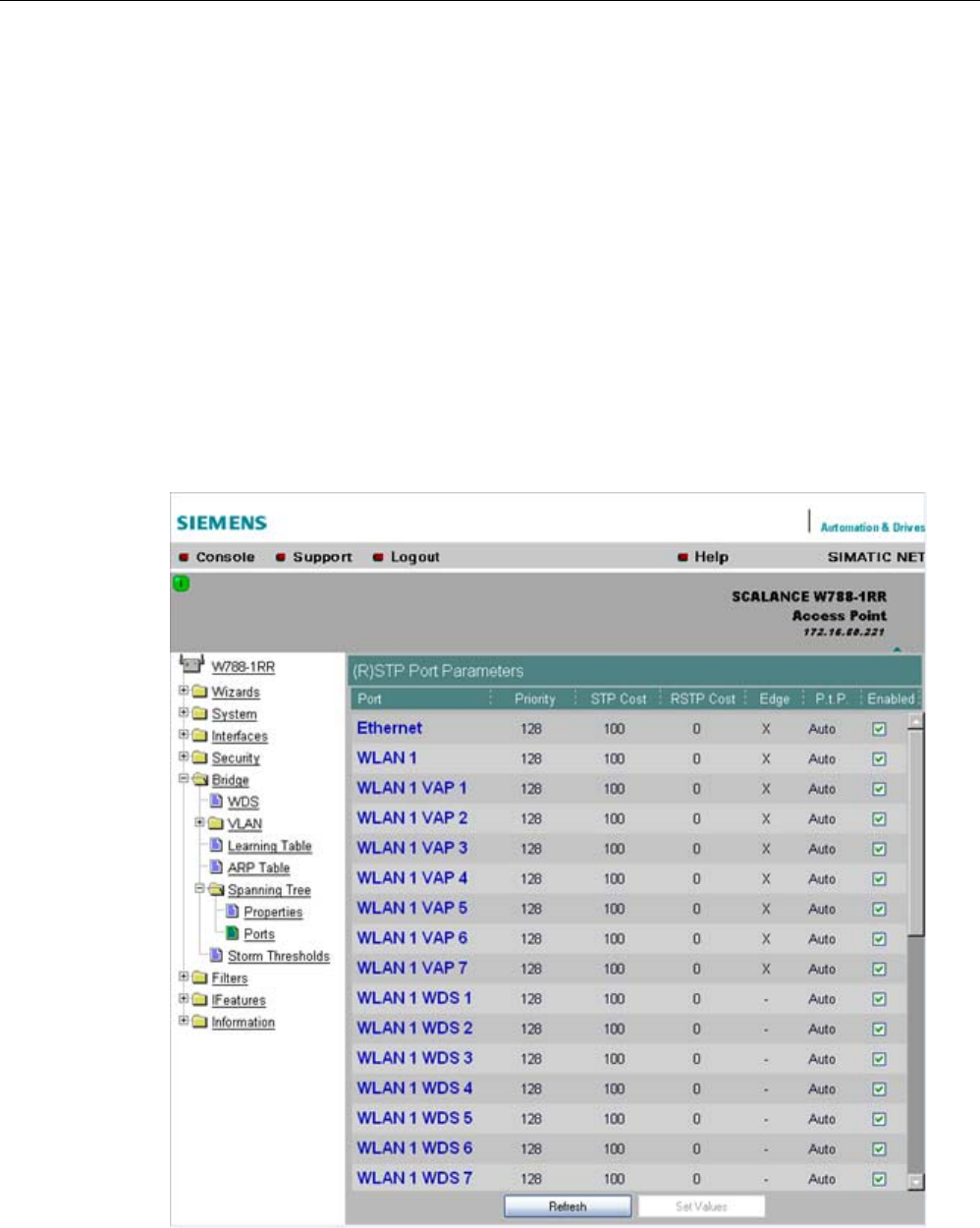
Configuration / project engineering
5.6 Configuration with Web Based Management
SCALANCE W786-xPRO
142 Operating Instructions, Release 08/2007, C79000-G8976-C221-02
has elapsed, the bridge attempts to reconfigure the network. The default for this
parameter is 20 seconds.
● Hello Time input box
Each bridge regularly sends configuration frames (BPDUs). The interval between two
such frames is the "Hello time". The default for this parameter is 2 seconds.
● Forward Delay input box
New configuration data is not used immediately by a bridge but only after the period
specified in the Forward Delay parameter. This ensures that operation is started with the
new topology only after all the bridges have the required information. The default for this
parameter is 15 seconds.
Spanning Tree Port settings
Port-specific parameters
This page displays the current port parameters. The settings are made either using the
automatic function of the SCALANCE W-700 or by the user.

Configuration / project engineering
5.6 Configuration with Web Based Management
SCALANCE W786-xPRO
Operating Instructions, Release 08/2007, C79000-G8976-C221-02 143
The eight columns of the port table show the following information:
● Port
Specifies the ports to which the information relates. WLAN1 VAP2, for example, relates to
the virtual access point VAP2 on the first WLAN interface.
● Priority
You set the priority of the ports of a bridge with this parameter.
If the path calculated by spanning tree is possible over several ports of a switch, the port
with the highest priority (in other words the lowest value for this parameter) is selected. A
value from 0 through 240 can be specified for the priority; the default is 128.
● STP Cost & RSTP
These parameters are used to calculate the path that will be selected. The lower the
value, the greater the probability that the corresponding path will be used. If several ports
of a bridge have the same value, the port with the lowest port number will be selected.
Depending on whether STP or RSTP was selected as the version, the value of STP Cost
or RSTP Cost will be used.
The calculation of the path costs is based mainly on the transmission speed. The higher
the achievable transmission speed, the lower the value for Path Cost should be.
Typical values for spanning tree and rapid spanning tree are as follows:
(The values can, however, also be set individually.)
Data rate Path costs STP Path costs RSTP
100 Mbps 19 200.000
54 Mbps 33 370.370
48 Mbps 36 416.667
36 Mbps 43 555.556
24 Mbps 53 833.333
18 Mbps 58 1.111.111
12 Mbps 83 1.666.667
11 Mbps 90 1.818.182
10 Mbps 100 2.000.000
9 Mbps 111 2.222.222
6 Mbps 166 3.333.333
5.5 Mbps 181 3.636.364
2 Mbps 500 10.000.000
1 Mbps 1000 20.000.000
● Edge
The following entries are possible in the this column.
yes There is an end device on this port.
no There is a spanning tree or rapid spanning tree device on this port.
If an end device is connected, a SCALANCE X-700 can switch over the port more quickly
without taking into account spanning tree frames. If a spanning tree frame is received
despite this setting, the port automatically changes to the no setting for further stations.
Note
If clients with the layer 2 tunneling function enabled connect to the access point, a
separate port is opened for each of these clients. These ports cannot, however, be
configured for Rapid Spanning Tree. The settings (for example, priority and path costs
etc.) of the cell over which the client is connected to the access point are adopted.

Configuration / project engineering
5.6 Configuration with Web Based Management
SCALANCE W786-xPRO
144 Operating Instructions, Release 08/2007, C79000-G8976-C221-02
Example:An L2T client is connected to the access point over the WLAN1 VAP3 interface.
The settings for WLAN1 VAP3 are: priority 128, path costs for STP of 100, path costs for
RSTP of 0 and the setting EdgePort enabled (in other words, there is an end device on this
port). These settings are adopted for the L2T port with one exception.
The Edge-Port enabled setting is not adopted because layer 2 tunneling clients and the ports
downstream from the client can never be edge ports.
● P.t.P.
There is a point-to-point link when two RSTP-compliant network components are
connected together over this port. There are three possible statuses :
– ForceTrue
Even with half duplex, a direct link is assumed.
– ForceFalse
Despite a full duplex connection, a point-to-point link is not assumed.
– Auto
Point-to-point is detected automatically. If the port is set to half duplex (shared media
connection), a direct link is not assumed.
– Example: A WDS connection between access points is always a half duplex
connection. With the setting ForceTrue, a direct connection is assumed. With Auto, a
direct connection is not assumed.
● Enabled
Shows whether spanning tree is enabled or disabled for the port.
Configuration of a port for (Rapid) Spanning Tree
If you click on a port name in the first column, you open the "(Rapid) Spanning Tree Port
Properties" page:
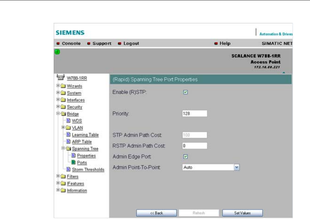
Configuration / project engineering
5.6 Configuration with Web Based Management
SCALANCE W786-xPRO
Operating Instructions, Release 08/2007, C79000-G8976-C221-02 145
"Enable (R)STP" check box
Enable this check box, if you want the port to use the (rapid) spanning tree protocol.
● Priority input box
Enter a value here for the port priority between 0 and 240.
● "Admin Path Cost" input box
Here, you can enter a value for the STP or RSTP Path Cost parameter. The relevant
value is then used depending on the selected version.
If you enter a zero for the RSTP value, the value for the path costs is calculated
automatically.
● "Admin Edge Port" check box
Enable this check box if an end device is connected to this port, otherwise a
reconfiguration of the network will be triggered by every link change.
● "Admin Point to Point Status" drop-down list box
There are three possible settings:
– Shared media Connection is selected:
This corresponds to "ForceFalse" in the port table.
– Point to Point Connection is selected:
This corresponds to "ForceTrue" in the port table.
– Point to Point Connection and Shared Media Connection are selected:
This corresponds to "Auto" in the port table.

Configuration / project engineering
5.6 Configuration with Web Based Management
SCALANCE W786-xPRO
146 Operating Instructions, Release 08/2007, C79000-G8976-C221-02
Note
Point-to-point means a direct connection between two stations. A shared media
connection would, for example, be a connection from the Ethernet port to a hub or a
WDS connection between two access points.
See also
CLI\BRIDGE\SPANNING menu command (Page 206)
CLI\BRIDGE\SPANNING\PORTS menu command (Page 207)
5.6.6.7 Storm Threshold menu command
Note
The "Storm Threshold" menu command is available in access point and in client mode. The
function can only be used in client mode if NAT is disabled.
Limitation of broadcast and multicast frames
Storm Threshold is the maximum number of broadcast or multicast frames per second
forwarded by the SCALANCE W-700. If this limit is exceeded, the SCALANCE W-700 stops
processing such frames for 30 seconds.
See also
CLI\BRIDGE\STORMTHR menu command (Page 208)
5.6.6.8 NAT menu command
Note
This menu command is available only with the following variants:
• SCALANCE W746-1PRO
• SCALANCE W746-1
• SCALANCE W747-1RR
• SCALANCE W747-1
• SCALANCE W78x (client mode only)
What is NAT?
With Network Address Translation (NAT), the IP address in a data packet is replaced by
another. NAT is normally used on a gateway between a private LAN and an external network
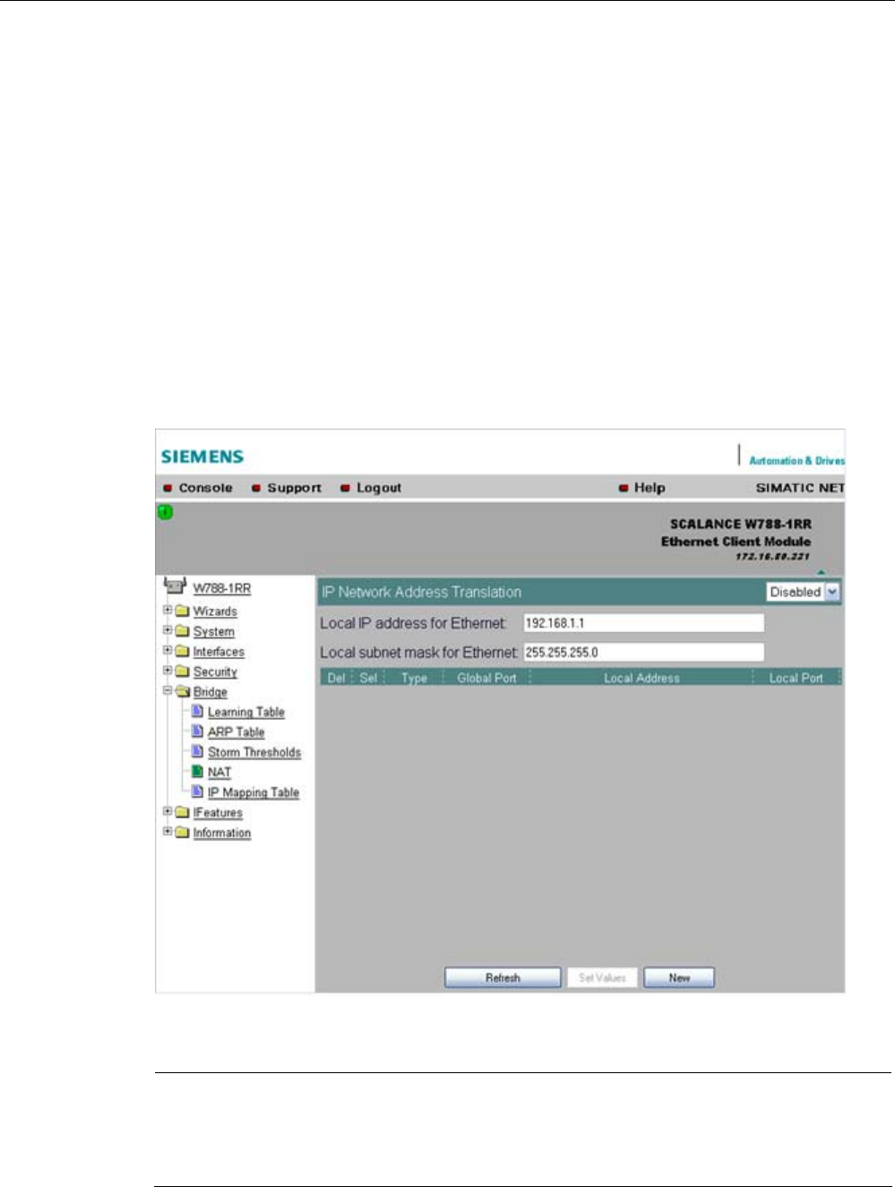
Configuration / project engineering
5.6 Configuration with Web Based Management
SCALANCE W786-xPRO
Operating Instructions, Release 08/2007, C79000-G8976-C221-02 147
with globally valid IP addresses. A local IP address of the internal LAN is changed to an
external global IP address by a NAT device at the gateway.
To translate the internal into the global IP address, the NAT device maintains a translation
list.
What is NAPT?
In "Network Address Port Translation" (NAPT) or "Port Address Translation" (PAT), several
internal source IP addresses are translated into the same external source IP address. To
identify the individual source nodes, the port of the source device is also stored in the
translation list of the NAT gateway and translated for the external address.
If several local clients send a query to the same external destination IP address over the
NAT gateway, the gateway enters its own external source IP address in the header of these
forwarded frames. Since the forwarded frames have the same global source IP address, the
NAT gateway assigns the frames to the clients using different port number.
Note
NAT/NAPT is possible only on layer 3 of the ISO/OSI reference model. To use the NAT
function, the networks must use the IP protocol.
When using the ISO protocol that operates at layer 2, it is not possible to use NAT.

Configuration / project engineering
5.6 Configuration with Web Based Management
SCALANCE W786-xPRO
148 Operating Instructions, Release 08/2007, C79000-G8976-C221-02
NAT properties of the SCALANCE devices
When using the following WLAN clients as a NAT gateway, the WLAN clients must be
connected with the local Ethernet devices over the Ethernet port:
● SCALANCE W746-1PRO
● SCALANCE W746-1
● SCALANCE W747-1RR
● SCALANCE W747-1
● W78x (in client mode)
The local IP address of the WLAN client on the Ethernet devices must be entered as the
gateway address.
The address assignment differs depending on the communication direction:
● From Ethernet device to access point: "Dynamic" address assignment (NAT)
The continuous address assignment is made automatically.
● From Access point to Ethernet device: "Static" address assignment (NAPT)
The address assignment is fixed and must be set as a parameter.
32 entries can be set as NAT gateways per WLAN client.
Configuration
Set the configuration on the IP Network Address Translation page with the following settings:
● Enable NAT
Click the "Enable" check box if you want to enable NAT.
Caution: The change is adopted only after a restart!
● Local IP
Here, you enter the local IP address for the Ethernet port of the WLAN client.
● Subnet Mask
Enter a subnet mask for the local Ethernet network here, if applicable.
● Del
Select the "Delete" check box if you want to delete the previous entries on this page.
● Sel
Select the "Select" check box if you want to enable the current entries.
● Type
Here, you select the assignment TCP or UDP for the following global port. Parameters for
TCP and UDP frames are set separately.
● Global Port
Enter the number of the global port (for TCP or UDP).
Note
If the port is already occupied by a local service (for example Telnet), a warning is
displayed. In this case, avoid using port 23 (Telnet), port 22 (SSH) and ports 80/443
(http/https: availability of the client with the WBM) as global port.
● Local Address
Here, you enter the local address of the Ethernet device.

Configuration / project engineering
5.6 Configuration with Web Based Management
SCALANCE W786-xPRO
Operating Instructions, Release 08/2007, C79000-G8976-C221-02 149
● Local Port
Here, you enter the number of the local port of the Ethernet device.
Note
The following instructions apply only to the IP parameter assignment using the PST tool.
When the module is accessed with PST by a configuration computer, the address
assignment differs depending on the interface:
• PST over the wireless interface:
The "global" address is changed.
• PST over the Ethernet interface:
The "local" address is changed.
See also
CLI\BRIDGE\NAT menu command (Page 209)
CLI\BRIDGE\NAT\STATIC menu command (Page 209)
5.6.6.9 IP Mapping Table menu command
Note
This menu command is available only with the following variants:
• SCALANCE W746-1PRO
• SCALANCE W746-1
• SCALANCE W747-1RR
• SCALANCE W747-1
• SCALANCE W78x in client mode
Note
IP mapping table
If layer 2 tunneling is configured for a client, the IP mapping table is not displayed.
WLAN access by several devices over a client
With the devices listed in the first paragraph, you can provide access to the WLAN for
several devices with one client. This means that you do not need to equip every device with
its own wireless client.
This so-called IP mapping is possible only if the connected devices are addressed only by IP
frames. Communication at MAC address level (ISO/OSI layer 2) can
● be established with one component whose MAC address is configured on the client,

Configuration / project engineering
5.6 Configuration with Web Based Management
SCALANCE W786-xPRO
150 Operating Instructions, Release 08/2007, C79000-G8976-C221-02
● be established with a maximum of eight components if the layer 2 tunneling function is
selected.
The layer 2 tunneling setting meets the requirements of industrial applications in which MAC
address-based communication takes place with several devices downstream from the client.
Clients with this setting cannot connect to standard Wi-Fi devices and access points with
firmware V3.0 or older.
MAC Mode
IP frames in the direction from the client to the access point always have the MAC address
of the WLAN interface as the source MAC address. As a result, the ARP tables at the access
point end always contain only the MAC address of the WLAN interface of the clients.
If there are further devices downstream from the client, the Auto Find 'Adopt MAC' option
should not be enabled. In this case, the MAC address would be assigned indiscriminately to
the first device that signals over Ethernet.
If there is only IP communication between the access point and the client, the default setting
"AdoptOwnMAC" can be retained. If frames based on MAC addresses are also sent by
devices downstream from the client, you will need to make the Adopt MAC settings
manually.
Select Autofind Adopt MAC or layer 2 tunneling.
MAC address/IP address assignment
The client maintains a table with the assignment of MAC address and IP address to be able
to send incoming IP frames to the correct MAC address. The "IP Mapping Table" menu
command displays this table. In principle, any number of device is can be reached
downstream from a client using IP. The client can manage up to eight devices. When a new
device is added, the oldest entry is deleted from the table to make space is for the new entry.
Since the data throughput of a wireless connection cannot be increased indefinitely, a
maximum of the devices should be managed by one client.
See also
Adopt MAC Address settings (only for clients or access points in client mode) (Page 76)
5.6.7 The Filters menu
5.6.7.1 Filters menu command
Note
The "Filters" menu and the corresponding menu commands are available only when you
operate the SCALANCE W78x in the access point mode. You can specify the mode in the
"System" menu.

Configuration / project engineering
5.6 Configuration with Web Based Management
SCALANCE W786-xPRO
Operating Instructions, Release 08/2007, C79000-G8976-C221-02 151
5.6.7.2 MAC Filters menu command
MAC filter
If the MAC filter is activated, communication with clients on the Ethernet side is possible only
when their source MAC addresses are entered in the table. As an alternative, there is a
possible setting with which access is denied for all specified MAC addresses. You can enter
a maximum of 50 MAC addresses in the table.
With IP mapping of a SCALANCE W78x in client mode, only the MAC address assigned to
this device is relevant, the MAC addresses of the devices downstream from it on the
Ethernet side are irrelevant for filtering.
If the "WDS" check box is selected, there is also filtering over the WDS ports.
See also
CLI\FILTERS\MAC1FLT menu command (Page 210)
5.6.7.3 MAC Dir Filter menu command
Restriction of the data traffic between MAC addresses
It is possible to filter the data traffic intended for wireless clients linked to the access point.
This filter is used to permit a specified MAC address access only to other specified MAC
addresses. You can specify several source addresses or entries for one destination address.
The communication of the destination address is then restricted to these entries. If a
destination address is not entered in the filter, it is not subjected to any restrictions.
See also
CLI\FILTERS\MAC2FLT menu command (Page 211)
5.6.7.4 Protocol Filter menu command
Protocol selection
Without protocol filtering, the SCALANCE W78x processes all data packets regardless of the
protocol being used. To increase data security and to reduce load, it can nevertheless be
useful to prevent communication using certain protocols.
Here, you are not restricted to the protocols included in the list in this menu. If necessary,
you can add your own entries to this list. You can specify a maximum of 50 Ethernet II
protocols for which filtering is required.
See also
CLI\FILTERS\PROTO menu command (Page 212)

Configuration / project engineering
5.6 Configuration with Web Based Management
SCALANCE W786-xPRO
152 Operating Instructions, Release 08/2007, C79000-G8976-C221-02
5.6.8 The I-Features menu
5.6.8.1 I-Features menu command
Note
The "I-Features" menu and the corresponding menu commands are available only when you
operate the SCALANCE W78x in the access point mode. You can specify the mode in the
"System" menu.
The iPCF menu command is available only for a SCALANCE W747-1RR, SCALANCE
W747-1 and an IWLAN/PB LINK.
5.6.8.2 iQoS menu command (in access point mode only)
Note
This function is not available in iPCF mode.
Client-specific bandwidth reservation
iQoS (Quality of Service) is technique with which clients are assigned a certain bandwidth.
Due to this assignment, there is a high probability that data transmission to these clients will
be within a defined period. This technique can be useful when response times must be
guaranteed. If non-iQoS-clients put too much load on the network, they can be logged off
from the AP to guarantee data traffic for iQoS clients.
Note
To ensure problem-free functioning of the iQoS mode, the number of clients with bandwidth
reservation is restricted to four.
Note
If the user reserves data for critical clients, this data rate also includes the frame header (in
other words, 802.11, MAC, IP, TCP, and S7 header). A SIMATIC user must therefore take
into account not only the net data during configuration but also the headers.

Configuration / project engineering
5.6 Configuration with Web Based Management
SCALANCE W786-xPRO
Operating Instructions, Release 08/2007, C79000-G8976-C221-02 153
Response Time
In the "Response Time" input box, you enter the required response time of the
SCALANCE W78x over the wireless interface. Remember that this value represents the
transmission time for the data from the SCALANCE W78x to the client. The data
transmission rate for nodes not included in the list is reduced according the values specified.
See also
CLI\IFEATURES\IQOS\WLAN1 (or \WLAN2 or \WLAN3) menu command (Page 212)
5.6.8.3 Forced Roaming on IP Down menu command (in access point mode only)
Note
Forced roaming on IP Down cannot be used in conjunction with iPCF or WDS on the same
WLAN interface.
Configuration
After selecting the "Forced Roaming on IP Down" check box, you can configure the following
parameters:
● Destination IP address
The IP address of the device for which a connection will be monitored.
● Interval (100 - 5000 ms)
Cycle time in milliseconds after which the IP connection will be checked.
● Maximum lost packets (1 - 5)
Maximum number of consecutive lost packets after which the WLAN interface is
deactivated.
See also
CLI\IFEATURES\FORCED_ROAM\WLAN1 (or \WLAN2 or \WLAN3) menu command
(Page 214)
5.6.8.4 Link Check menu command (in access point mode only)
Note
This function is not available in iPCF mode.

Configuration / project engineering
5.6 Configuration with Web Based Management
SCALANCE W786-xPRO
154 Operating Instructions, Release 08/2007, C79000-G8976-C221-02
Note
With the Link Check function, you can only monitor connections to WLAN clients; use along
with redundancy or WDS is not possible.
Table of monitored devices
In the drop-down list box of the "Link Check" title line, you decide whether connection
monitoring is enabled or disabled. Only connections to devices for which the check box in
the "Sel" column is selected will be monitored.
You can delete entries in the table by selecting the relevant check box in the "Del" column
and clicking the "Set Values" button. You can create new list entries after clicking the "New"
button. You can then enter the MAC address and the monitoring time.
System event for connection abort
You can specify how the SCALANCE W78x reacts to a connection abort (or to the
reestablishment of a connection) in the System > Events menu.
See also
CLI\IFEATURES\LINKCHECK menu command (Page 215)
5.6.8.5 Redundancy menu command (in access point mode only)
Note
The redundancy function described here is available only for SCALANCE W78x devices that
have more than one wireless adapter and that are not operated in iPCF mode.
You can use the WEP encryption method.
Configuration with sysName
Instead of the MAC addresses, you can also configure the redundant partners with the
"sysName" parameter. Beacons contain this parameter which is why the redundant device is
detected using beacons.
Note
With the firmware update to to V3.0, the SCALANCE W78x-xRR devices need to be
reconfigured if you use WDS or redundancy and use the MAC address and not the
sysName.
These functions are then based on the MAC address that changes with the introduction of
VAPs with V3.0.

Configuration / project engineering
5.6 Configuration with Web Based Management
SCALANCE W786-xPRO
Operating Instructions, Release 08/2007, C79000-G8976-C221-02 155
Note
If IEEE 802.1x or WPA is used, a "private key" must be selected for the redundant
connection.
See also
CLI\IFEATURES\REDUNDANCY menu command (Page 216)
5.6.8.6 IP Alive menu command (in access point mode only)
Table of monitored devices
In the "IP Alive" drop-down list box, you decide whether connection monitoring is enabled or
disabled. Only connections to IP addresses for which the check box in the "Sel" column is
selected will be monitored.
You can delete entries in the table by selecting the relevant check box in the "Del" column
and clicking the "Set Values" button. You can create new list entries after clicking the "New"
button. You can then enter the MAC address and the monitoring time.
Monitoring independent of the port
With IP-Alive, you specify a monitoring time for an IP address and a port. If you do not want
to monitor a particular port but rather only the data traffic from a particular IP address, simply
enter 0 in Port. This resets the monitoring with each frame from this IP address.
System event for connection abort
You can specify how the SCALANCE W78x reacts to change in the IP-Alive status in the
System > Events menu.
Note
The IP-Alive function is not available in iPCF mode.
Note
If the IP Alive function does not detect any data traffic for the specified time, the status of the
IP address is set to "Offline" and the error status activated. The error status must be
confirmed before the IP Alive function sets the status for active data traffic back to "Online".
See also
CLI\IFEATURES\IP_ALIVE menu command (Page 217)

Configuration / project engineering
5.6 Configuration with Web Based Management
SCALANCE W786-xPRO
156 Operating Instructions, Release 08/2007, C79000-G8976-C221-02
5.6.9 The Information menu
5.6.9.1 Information menu command
System events and information on the protocols
The pages of this menu display tables contain information on system events and on the
behavior of the protocols (IP, TCP, UDP, and ICMP, SNMP).
Updating the display
Most pages have the "Refresh" button at the bottom edge with which you can update the
display. The "Client List" menu command also allows you to update automatically. To
activate this, select the "Update" check box.
See also
CLI\INFORM menu command (Page 217)
5.6.9.2 Log Table menu command
Logging system events
This page lists system events and the time at which they occurred. You can specify which
events are included here in the System > Events menu.
If you position the mouse pointer over a time value, the system time and date are displayed.
See also
CLI\INFORM\LOG menu command (Page 218)
5.6.9.3 Auth Log menu command
Logging authentication
The pages of this menu contain a table with information on successful or failed
authentication attempts.
See also
CLI\INFORM\AUTHLOG menu command (Page 219)
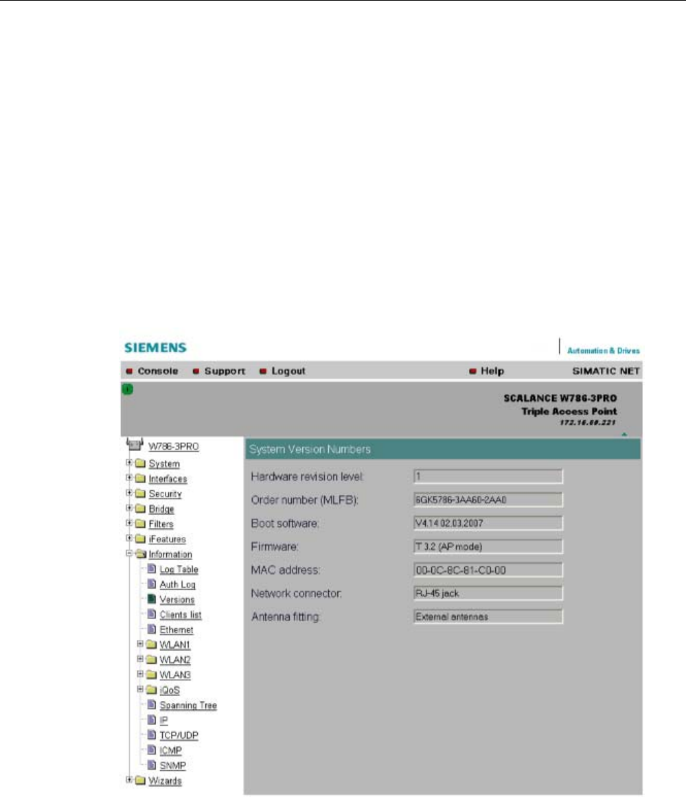
Configuration / project engineering
5.6 Configuration with Web Based Management
SCALANCE W786-xPRO
Operating Instructions, Release 08/2007, C79000-G8976-C221-02 157
5.6.9.4 Versions menu command
Current versions and order numbers
1. Hardware version
2. Order number (MLFB)
3. Boot software version
4. Firmware version
5. Ethernet MAC address
6. Type of network attachment (RJ-45 electric/ST optical)
7. Antenna mounting (internal/external)

Configuration / project engineering
5.6 Configuration with Web Based Management
SCALANCE W786-xPRO
158 Operating Instructions, Release 08/2007, C79000-G8976-C221-02
5.6.9.5 Client List menu command
Note
This menu command is available only in access point mode.
Logged-on clients
All the clients logged on at the SCALANCE W78x along with certain additional information
(wireless channel, status etc.) are displayed here.
● MAC Address
the MAC address of the client.
● If#
This specifies the wireless interface over which the client is connected.
● Signal
The signal strength of the client. The higher the value, the better the signal. The user can
choose between percentage and dBm.
● Age
Displays the time that has elapsed since the last client activity was detected.
● Sec
This indicates which encryption is active.
● Channel.
The current channel over which the client communicates with the SCALANCE W78x.
● State
The current state of the clients. Associated means that the client is logged on.
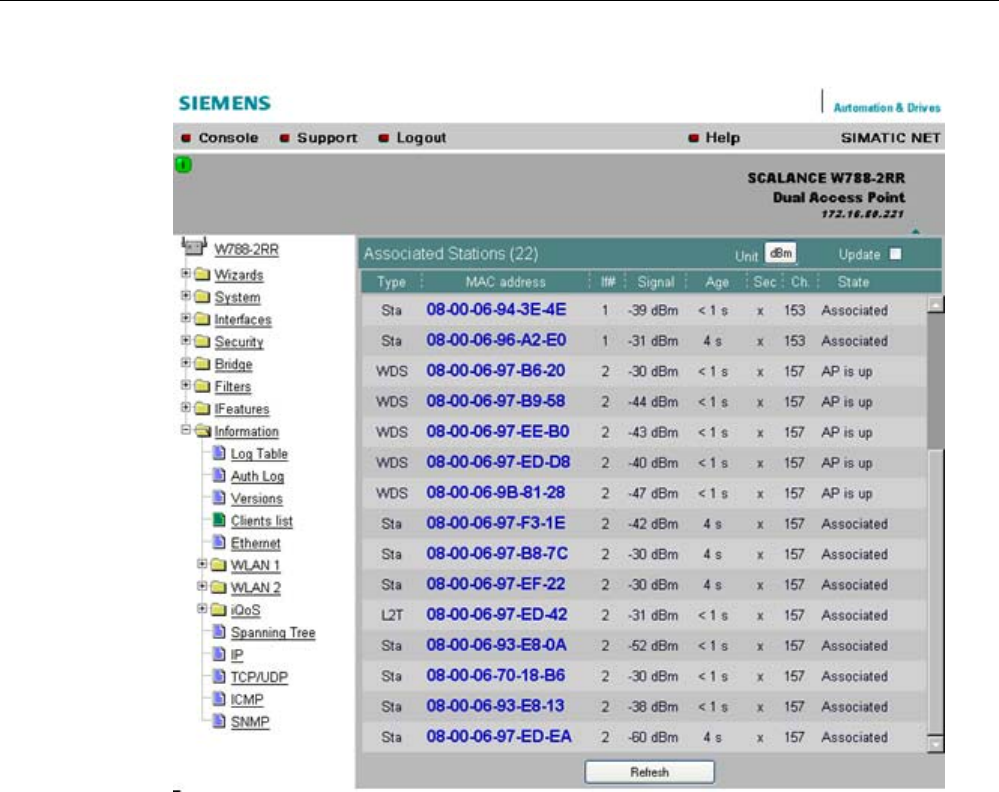
Configuration / project engineering
5.6 Configuration with Web Based Management
SCALANCE W786-xPRO
Operating Instructions, Release 08/2007, C79000-G8976-C221-02 159
By selecting the "Update" check box, the list is updated automatically every 3 seconds. If you
click on the MAC address of a client, you will receive additional information on this client.
See also
CLI\INFORM\WLAN1 (or \WLAN2 or \WLAN3) menu command (Page 219)
5.6.9.6 Ethernet menu command
Information on the Ethernet interfaces
This menu command provides information on the current settings of the Ethernet interface.
The current operating data is also displayed here.
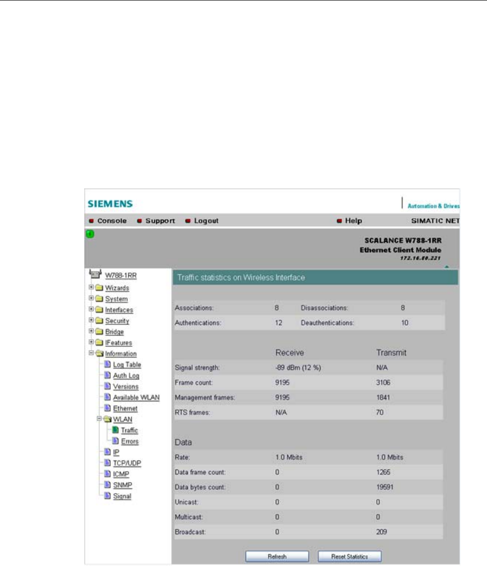
Configuration / project engineering
5.6 Configuration with Web Based Management
SCALANCE W786-xPRO
160 Operating Instructions, Release 08/2007, C79000-G8976-C221-02
5.6.9.7 WLAN menu command
Information on the WLAN interface
This menu command provides information on the current settings of the WLAN interface.
The current operating data is also displayed here. There is a separate menu for each
wireless interface when the model has more than one wireless interface.
Traffic
Statistics of the data to be transmitted are displayed here.
● Association / Authentication Frames
The frames relevant for registration are counted. A distinction is made between the
registration frames Association and Authentication and the deregistration frames
Disassociation and Deauthentication.

Configuration / project engineering
5.6 Configuration with Web Based Management
SCALANCE W786-xPRO
Operating Instructions, Release 08/2007, C79000-G8976-C221-02 161
● Signal strength
The signal strength is displayed as an average of the last received frames or at the
sending end of the last received acknowledge frames.
● Frame count
Counter for all successfully received or sent frames.
● Management frames
Counts all received or sent management frames.
● RTS frames
Is incremented when a CTS frame is received in response to an RTS frame.
● Rate
Displays an average data rate of the most recently received or sent data frames.
● Data frame count
Counts all received or sent data packets.
● Data bytes count
Displays the sum of all received or sent bytes in a data frame.
● Unicast
Sum of all received or sent data unicasts.
● Multicast
Sum of all received or sent data multicasts.
● Broadcast
Sum of all received or sent data broadcasts.
Errors
This page displays statistics of the transmission errors that have occurred. A high error rate
indicates a bad connection.
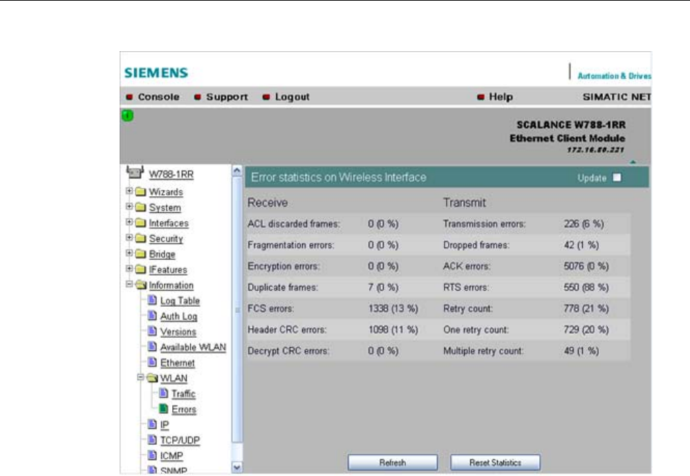
Configuration / project engineering
5.6 Configuration with Web Based Management
SCALANCE W786-xPRO
162 Operating Instructions, Release 08/2007, C79000-G8976-C221-02
Receive Errors
● ACL discarded frames
Displays all client registration attempts that were blocked by the Access Control List.
● Fragmentation errors
Sum of all failed fragmentations. One of the fragments was not received or received too
late.
● Encryption errors
Is incremented if a frame is received in which the WEP bit is set and the device operates
without encryption, or the reverse situation when a packet is received without a WEP bit
and encryption is enabled.
● Duplicate frames
Sum of all frames received twice.
● FCS errors
Sum of all packets received in which the checksum was incorrect.
● Header CRC error
Sum of all packets received in which the header checksum was incorrect.
● Decrypt CRC error
Sum of all packets received in which the checksum of the encrypted data buffer was
incorrect.

Configuration / project engineering
5.6 Configuration with Web Based Management
SCALANCE W786-xPRO
Operating Instructions, Release 08/2007, C79000-G8976-C221-02 163
Transmit Errors
● Transmission errors
Is incremented when a frame cannot be sent successfully despite hardware retries.
● Dropped frames
Number of packages that were dropped either when the packet was not sent despite all
retries or packets that had not been sent when a node deregistered.
● Acknowledged errors
Sum of all packets sent that were not confirmed by an acknowledge.
● RTS errors
Sum of all sent RTS frames that were not acknowledged by a CTS.
● Retry count
Sum of all frames sent successfully that required one or more retries.
● One retry count
Sum of all frames sent successfully that required exactly one retry.
● Multiple retry count
Sum of all frames sent successfully that required more than one retry.
Note
The percentages shown following the errors relate to the total number of received / sent
frames.
Overlap AP
Note
This menu command is available only in access point mode.
For optimum data throughput, it is important that the set wireless channel is not used by
other access points. In the 2.4 GHz band (802.11b or 802.11g), there is overlapping of the
wireless channels so that an access point occupies not only the set channel but also the two
or three adjacent channels. You should therefore make sure that there is adequate channel
spacing to neighboring access points.
The "Overlap AP" page shows all access points that are visible on the set or adjacent
channels (at 2.4 GHz). If entries exist here, the maximum data throughput of the access
point will be restricted.
● Type
Shows the type of connection. The types AP (infrastructure mode) and AdHoc exist.
● MAC address
The MAC address of the wireless devices.
● Channel
The channel on which the found wireless device transmits.
● Signal
Shows the signal strength with which the other wireless devices are received at the AP.
The stronger the signal, the greater the probability that they interfere with each other.

Configuration / project engineering
5.6 Configuration with Web Based Management
SCALANCE W786-xPRO
164 Operating Instructions, Release 08/2007, C79000-G8976-C221-02
There is also the possibility that they interfere with each other even at low signal
strengths.
● Age
Shows when the last activity was detected by the wireless device.
● SSID
Shows the SSID of the other wireless device.
5.6.9.8 iQoS menu command
Information on bandwidth reservation
The pages of this menu provide information on iQoS. The clients are grouped as follows:
● Critical Compliant (CC)
This involves clients that were defined as critical and that are currently meeting the
requirements you set for the bandwidth and response time.
● Critical Non-Compliant (CNC)
The CNC clients are also clients with strict requirements regarding the response time and
bandwidth. In contrast to the CC clients, however, these clients are not currently meeting
these requirements.
● Non-Critical Satisfied (NCS)
These clients do not have fixed requirements regarding the response time and minimum
bandwidth. Their communication is not currently restricted by iQoS.
● Non-Critical Regulated (NCR)
These clients are also non-critical clients whose communication is, however, currently
being restricted by iQoS in favor of critical clients.
● Non-Critical Non-Responsive (NCNR)
Some clients that require no acknowledgment whatsoever for their communication (for
example UDP traffic) cannot be regulated by iQoS. These are classified as NCNR.
See also
CLI\IFEATURES\IQOS\WLAN1 (or \WLAN2 or \WLAN3) menu command (Page 212)
5.6.9.9 Spanning Tree menu command
Status of the Spanning Tree protocol
The upper part of the page shows the "RootID" and the "BridgeID". Both IDs are made up of
their priority and their MAC address. Together, this results in the 16 character long ID. The
RootID is the ID of the bridge that is currently the root bridge. The BridgeID shows the ID of
the local device.
Below this, you can see values for the Topology Change event. The first value is a counter
indicating how often the tree structure has changed since restarting. The value beside this,
shows the time since the last switchover event.
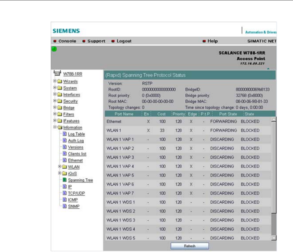
Configuration / project engineering
5.6 Configuration with Web Based Management
SCALANCE W786-xPRO
Operating Instructions, Release 08/2007, C79000-G8976-C221-02 165
Below this, you will see the following port-related information:
● Port Name
Plain language name of the port, for example Ethernet or WLAN1 WDS1.
● Enabled
Indicates whether the (R)STP is enabled for this port. If the port is not enabled, no further
frames are forwarded over this port.
● Cost
Indicates the path costs for the port.
● Priority
Indicates the current priority of the port.
● Edge
Shows whether or not the port is an edge port.
● P.t.P.
Shows whether or not the AP is connected directly to another (R)STP device

Configuration / project engineering
5.6 Configuration with Web Based Management
SCALANCE W786-xPRO
166 Operating Instructions, Release 08/2007, C79000-G8976-C221-02
● Port State
With STP, a port can adopt three states:
– Discarding
No frames are forwarded from or to this port. The port has been disable by the user or
the protocol (for example, when a redundant path has been detected).
– Learning
The port receives packets in the same way as in listening mode, but does not forward
them. The MAC addresses are also entered in the "Learning Bridge".
– Forwarding
The port is fully enabled. Frames can be received and sent.
– Disabled
The port is not currently in use.
● State
Here, the state of the port in relation to the root bridge is displayed. The "ROOT" state
means that the port is connected directly with the root bridge. "DESIGNATED" identifies
all ports that are not directly at the root but that are enabled. Ports that are blocked are in
the "BLOCKED" state.
5.6.9.10 IP, TCP/IP, ICMP, SNMP menu command
Information on protocols
The pages of this menu show information on the IP, TCP, UDP, ICMP, and SNMP protocols
in the form of tables.
Note
There are no CLI commands for this menu command.
5.6.9.11 Signal Recorder menu command
Note
The signal recorder is available only for clients and access points in client mode and the
IWLAN/PB-Link PN IO.
Signal strength indicators
The Signal Recorder can record or display the signal strength of the connected access point.
Using this data, you can locate areas with an inadequate signal strength. The Signal
Recorder can be particularly advantageous when the client moves along a fixed path (for
example suspension track).

Configuration / project engineering
5.6 Configuration with Web Based Management
SCALANCE W786-xPRO
Operating Instructions, Release 08/2007, C79000-G8976-C221-02 167
● Procedure for SCALANCE W-700 clients:
Using the URL
http://<IP address>/Signal.txt
or the URL
http://<IP address>/Signal.log
you can download the generated signal file. If you are not yet logged in, this opens the
login window in which you must log in.
● Procedure for IWLAN/PB LINK PNIO:
1. Enable the FTP server
2. Enter ftp <ip address> in a DOS box.
3. Log in as admin (default password admin)
4. Enter the command get signal.txt.
The signal.txt file is then stored in the directory from which the ftp command (point 2)
originated.
Displaying the instantaneous value
The upper half of the window contains an instrument for displaying the graphic
representation of the currently calculated dBm value in real time. Depending on your browser
and the network load, the display is updated approximately every 500 ms. Apart from the
graphic display, the current dBm value is also displayed in plain language. The MAC address
of the AP with which the ECM is currently connected along with the frequency, channel and
transmission rate are also displayed and updated. You can start or stop the graphic display
with the "Start display" and "Stop display" buttons.
Note
Working with the graphic display can cause a not insignificant network load that can disturb
time- and throughput-critical processes (PNIO).
Recording a series of measurements
The lower half of the window includes not only the operator controls for graphic display of the
instantaneous value but also the controls for the actual signal recorder. You can set the
interval between the acquisition of two measuring points as well as the total number of
measuring points. The recorder is controlled by the "Start recording" and "Stop recording"
buttons.
As soon as measuring points have been recorded successfully and the recorder has been
stopped, the "Save recorder file" and "Display recorder file" buttons are enabled. With the
"Save" button, the measured values can be loaded directly from the ECM as a file in CSV
format and imported into a suitable evaluation program.
The CSV file contains the MAC address of the AP for every measuring point, the current
number of the measurement, the raw value of the RSSI, the dBm value and its
corresponding percentage value, a roaming indicator, the channel and the transmission rate.
The "Display record file" button opens a pop-up window in which the measured values over
time is already available in graphic form. The dBm values are shown over time. If the ECM
roams during the measurement, blue bars indicate the event. If you move the mouse pointer
over such a bar or over the flag at the top of the bar, a tooltip with the MAC addresses of the
two access points appears.

Configuration / project engineering
5.6 Configuration with Web Based Management
SCALANCE W786-xPRO
168 Operating Instructions, Release 08/2007, C79000-G8976-C221-02
With the "Print graph" button, it is easy to print the table. You will, however, need to make
certain settings in the browser.
● Mozilla Firefox 1.5:
In the "File" => "Page setup..." dialog, make sure that the "Print Background (colors &
images) check box is enabled in the "Options" group box.
● Microsoft Internet Explorer 6.0:
In "Tools" => "Internet Options" => "Advanced", the "Print background colors and images"
check box must be enabled under "Printing".
The signal recorder itself does not cause any significant load in the network that could affect
other processes.
Both parts of the signal recorder can be operated independently.
Below, you will find a few tips that will help you to obtain useful measurements with the
signal recorder:
● Use a fixed data rate in the configuration.
● Where possible, the ipcf mode with as low an update time as possible should be set for
the measurements.
● Make sure that there is enough data communication during the measurement because
the statistics functions evaluate incoming frames.
● The measurement setup should be run through 2-3 times with the same parameters to
find out whether losses of signal strength always occur at the same position.
● Selective measurements at a fixed position should be made over a certain time.
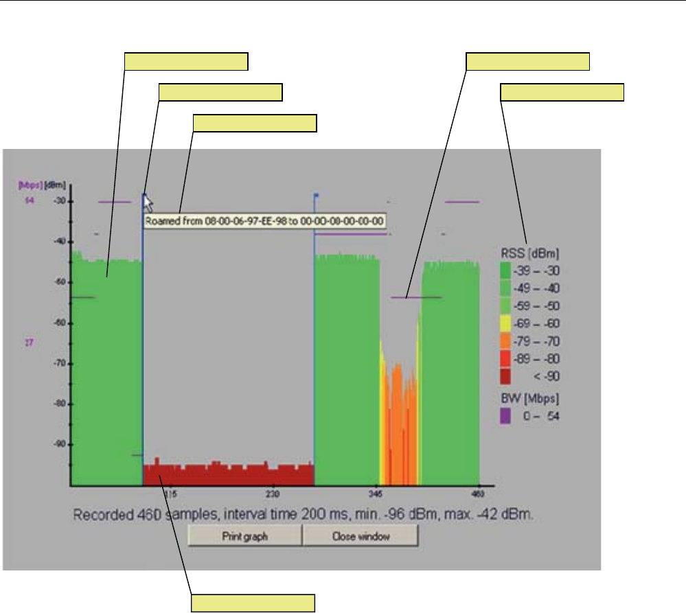
Configuration / project engineering
5.6 Configuration with Web Based Management
SCALANCE W786-xPRO
Operating Instructions, Release 08/2007, C79000-G8976-C221-02 169
/HJHQG5RDPLQJLQGLFDWRU
7RROWLS
%DQGZLGWKGDWDUDWH6LJQDOOHYHO
1RLVHIORRU
Figure 5-2 Screen display of the measured values
Roaming indicator
This value appears when the client connects to another or to no AP and the MAC address of
the AP changes as a result.
Bandwidth/data rate
The bandwidth/data rate is not displayed over the entire screen since it could overlap the
signal level.
Noise floor
The noise floor represents the lower end of the technically possible transmission of the
device. This means that when the noise floor is exceeded (the useful signal is louder than
the noise floor), this is where the system dynamics begins. For this reason, this level is
visible only when the client has no connection to an AP (indicated in the figure above by the
MAC address 00-00-00-00-00-00).
Legend
BW bandwidth in Mbps
RSS received signal strength in dBm
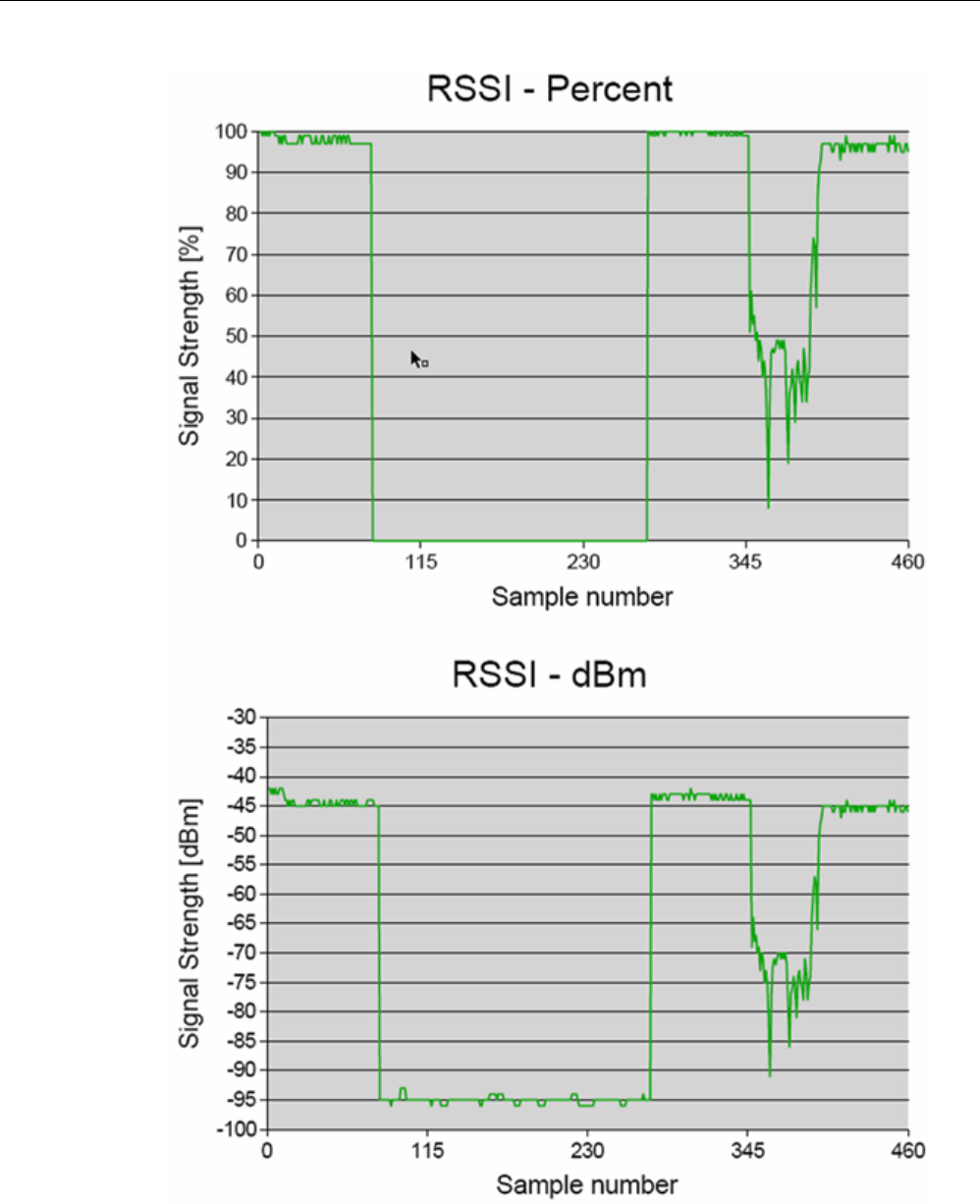
Configuration / project engineering
5.6 Configuration with Web Based Management
SCALANCE W786-xPRO
170 Operating Instructions, Release 08/2007, C79000-G8976-C221-02
Figure 5-3 Comparison of the measured value display as a percentage and in dBm

Configuration / project engineering
5.6 Configuration with Web Based Management
SCALANCE W786-xPRO
Operating Instructions, Release 08/2007, C79000-G8976-C221-02 171
See also
CLI\INFORM\SIGNAL menu command (Page 220)

Configuration / project engineering
5.7 Configuration with the Command Line Interface
SCALANCE W786-xPRO
172 Operating Instructions, Release 08/2007, C79000-G8976-C221-02
5.7 Configuration with the Command Line Interface
5.7.1 General information on the Command Line Interface
Introduction
With the Command Line Interface (CLI), you can configure all the settings of a
SCALANCE W-700 and an IWLAN/PB Link. The CLI therefore provides the same options as
Web Based Management. You should read the detailed explanations of the parameters in
the section "Configuration with Web Based Management".
The CLI also allows remote configuration over Telnet.
Note
You should only use the command line interface if you are an experienced user. Even
commands that bring about fundamental changes to the configuration are normally executed
without a prompt for confirmation.
Configuring an IWLAN/PB Link with the CLI
The IWLAN/PB LINK only uses configuration over CLI. The "Comment" column in the
following table shows which command is available for which device.
Starting the CLI in a Windows console
Follow the steps outlined below to start the Command Line Interface in a Windows console:
1. Open a Windows console and type in the command "telnet" followed by the IP address of
the SCALANCE W7xx:
C:\>telnet <IP address>
2. Enter your login and password.
As an alternative, you can also enter the command "telnet" followed by the IP address of
the SCALANCE W-700 in the Start > Run menu.
Starting the CLI in Web Based Management
You can also call the CLI from Web Based Management. Click on the Console entry in the
upper menu bar of Web Based Management. A console opens in which you can log on with
your login and password. The IP address is adopted by Web Based Management.
Note
This function is not available in the Internet Explorer as of version 7.

Configuration / project engineering
5.7 Configuration with the Command Line Interface
SCALANCE W786-xPRO
Operating Instructions, Release 08/2007, C79000-G8976-C221-02 173
Shortcuts for commands
As an alternative, instead of entering full CLI commands, you can simply enter the first letter
or the first few letters of the command and then press the Tab key. The Command Line
Interface then displays a command starting with the letter or letters you typed in. If the
command displayed is not the command you require, press the Tab key again to display the
next command.
Directory structure
Before you can enter a command in the Command Line Interface, you must first open the
required menu or submenu. The following tables contain the commands of a menu and a
description of them. The menu containing the commands is shown before the table. The
table lists only the commands themselves.
Symbols for representing CLI commands
CLI commands generally have one or more parameters that are represented in the syntax
description as follows:
● Mandatory parameters are shown in pointed brackets.
Example: <IP address>
● Optional parameters are shown in square brackets.
Example: [E|D]
If you omit an optional parameter, the commands output the currently set value.
● Alternative input values are separated by the pipe character. In this case, you specify one
of the listed values as the parameter.
Example: [E|D]
you enter either "E" or "D".
● If a numeric value is required as a mandatory parameter, you can also specify a range of
values:
Example: <0 ... 255>
You enter a value between 0 and 255.
Cross-menu commands
You can use the commands in the following table in any menu.
CLI\ ... >
Comment Command Description
IWLAN/
PB LINK
W744 W746 W747 W78x W78x
RR
/ Moves you one menu level higher. ✔ ✔ ✔ ✔ ✔ ✔
? Displays the commands and submenus
available in the menu.
✔ ✔ ✔ ✔ ✔ ✔
Cannot be called using the command shortcuts.
exit Closes the CLI/Telnet session.
✔ ✔ ✔ ✔ ✔ ✔
restart Restarts the SCALANCE W7xx Cannot be called using the command shortcuts.

Configuration / project engineering
5.7 Configuration with the Command Line Interface
SCALANCE W786-xPRO
174 Operating Instructions, Release 08/2007, C79000-G8976-C221-02
Comment
✔ ✔ ✔ ✔ ✔ ✔
info Displays information on the current
menu item.
✔ ✔ ✔ ✔ ✔ ✔
5.7.2 The CLI\SYSTEM menu
5.7.2.1 CLI\SYSTEM menu command
Mode and locale setting
With the commands in this menu, you set the locale and mode (access point or client).
CLI\SYSTEM>
Comment Command Description
IWLAN/
PB LINK
W744 W746 W747 W78x
W78x
RR
E
Access Point
D Client
apmode [E|D|H]
H HiPath Access Point
(only available for
SCALANCE W788-2RR)
ᅳ ᅳ ᅳ ᅳ ✔ ✔
This command is not available in the version for USA.
country [xx|?] Specifies properties for specific
countries. The country codes
("xx") correspond to ISO 3166.
You can see which countries you
can set after entering the "country
?" command. A list of countries
appears with the corresponding 2-
digit code.
✔ ✔ ✔ ✔ ✔ ✔
Maximum of 255 characters. If you want to use the
name in WDS or redundancy, the maximum length is
32 characters.
name [system name] Assigns a value to the
sysName
MIB variable.
✔ ✔ ✔ ✔ ✔ ✔
Maximum of 255 characters.
location [location] Assigns a value to the
sysLocation
MIB variable. ✔ ✔ ✔ ✔ ✔ ✔
Maximum of 255 characters.
contact [name] Assigns a value to the
sysContact
MIB variable. ✔ ✔ ✔ ✔ ✔ ✔
ping [-c n | -s] For connection test to partner. Telnet only

Configuration / project engineering
5.7 Configuration with the Command Line Interface
SCALANCE W786-xPRO
Operating Instructions, Release 08/2007, C79000-G8976-C221-02 175
Comment
<IP|Name> -c (counter) for the number n of
ICMPs
-s stops the connection test for all
devices
✔ ✔ ✔ ✔ ✔ ✔
Maximum of 31 characters.
password [admin|user]
[password] Specifies a password for access
to the device. ✔ ✔ ✔ ✔ ✔ ✔
5.7.2.2 CLI\SYSTEM\IP menu command
IP address assignment
With the commands in this menu, you specify how the device obtains its IP address.
CLI\SYSTEM\IP>
Comment Command Description
IWLAN/
PB LINK
W744 W746 W747 W78x
W78x
RR
dhcp [E|D] Enable / disable DHCP server. ᅳ ✔ ✔ ✔ ✔ ✔
Specifies how a device will be
identified:
M MAC address
N Device name
dhcptype [M|N|C]
C Client ID
ᅳ ✔ ✔ ✔ ✔ ✔
clientid Specifies a client-ID for the
device.
ᅳ ✔ ✔ ✔ ✔ ✔
When you enter a valid IP address, enabled DHCP is
automatically disabled.
ip [IP address] Specifies the IP address for the
SCALANCE W7xx.
ᅳ ✔ ✔ ✔ ✔ ✔
subnet [subnet mask] Specifies the subnet mask. ᅳ ✔ ✔ ✔ ✔ ✔
gateway [IP address] Specifies the IP address of the
router.
ᅳ ✔ ✔ ✔ ✔ ✔
Default value: 64
ttl [TTL value] Sets the TTL (Time To Live)
parameter. ᅳ ✔ ✔ ✔ ✔ ✔
See also
IP Settings menu command (Page 100)

Configuration / project engineering
5.7 Configuration with the Command Line Interface
SCALANCE W786-xPRO
176 Operating Instructions, Release 08/2007, C79000-G8976-C221-02
5.7.2.3 CLI\SYSTEM\SERVICES menu command
Configuration options
With the commands in this menu, you select the services (SNMP, Web Based Management
etc.) with which access to the device will be possible.
CLI\SYSTEM\SERVICES>
Comment Command Description
IWLAN/
PB LINK
W744 W746 W747 W78x
W78x
RR
Only WEB and SNMP
telnet [E|D] Enable / disable configuration of the
device over Telnet. ✔ ✔ ✔ ✔ ✔ ✔
ttimeout [E|D] Enables / disables the time
restriction for a Telnet session.
✔ ✔ ✔ ✔ ✔ ✔
ttimeout [time in s] Specifies the time after which a
Telnet section is closed if there is no
further input.
✔ ✔ ✔ ✔ ✔ ✔
ssh [E|D] Enables / disables configuration of
the device over secure Telnet.
✔ ✔ ✔ ✔ ✔ ✔
snmp [E|D] Enable / disable SNMP. ᅳ ✔ ✔ ✔ ✔ ✔
mail [E|D] Enable / disable E-mail. ᅳ ✔ ✔ ✔ ✔ ✔
web [E|D] Enable / disable configuration of the
device over Web Based
Management.
ᅳ ✔ ✔ ✔ ✔ ✔
httpsonly [E|D] Enable / disable access for
configuring only over HTTPS.
ᅳ ✔ ✔ ✔ ✔ ✔
ping [E|D] Enable / disable response of the
device to Ping.
✔ ✔ ✔ ✔ ✔ ✔
psu [E|D] Enable / disable access to the
device with the Primary Setup Tool.
If this access option is deactivated,
configuration data can only be read
with the Primary Setup Tool.
ᅳ ✔ ✔ ✔ ✔ ✔
ftpserv [E|D] Enable / disable the FTP server on
the device. Required for
downloading the Signal.TXT file
generated by the Signal Recorder.
✔ ᅳ ᅳ ᅳ ᅳ ᅳ
See also
Services menu command (Page 100)

Configuration / project engineering
5.7 Configuration with the Command Line Interface
SCALANCE W786-xPRO
Operating Instructions, Release 08/2007, C79000-G8976-C221-02 177
5.7.2.4 CLI\SYSTEM\RESTARTS menu command
Default settings and restart
With the commands in this menu, you can restore the factory settings of the device and
restart the device.
CLI\SYSTEM\RESTARTS>
Comment Command Description
IWLAN/
PB LINK
W744 W746 W747 W78x
W78x
RR
This command can be called from all menus, however
not using the shortcut commands.
restart Restart the device.
✔ ✔ ✔ ✔ ✔ ✔
After restoring the factory settings, restart manually.
memreset Resets the factory settings and
triggers a restart (the protected
settings are not deleted). ✔ ✔ ✔ ✔ ✔ ✔
defaults Resets to the factory settings (the
protected settings are also
deleted).
✔ ✔ ✔ ✔ ✔ ✔
See also
Restart menu command (Page 101)
5.7.2.5 CLI\SYSTEM\EVENT menu command
Syntax of the Command Line Interface
For each of the four possible reactions E-mail, trap, log and fault, either "E" (Enabled =
setting is enabled) or "D" (Disabled = setting is disabled) must be entered as the parameter.
If, for example, an E-mail is sent when the device restarts (first parameter "CW") and an
entry is made in the log table but neither a trap nor an error is generated, the following
command must be entered:
setec CW E D E D (for SCALANCE W-700)
setec CW D E D (for IWLAN/PB LINK)
Note
The IWLAN/PB LINK does not support E-mail. As a result, the second parameter for
enabling/disabling the E-mail option is omitted.

Configuration / project engineering
5.7 Configuration with the Command Line Interface
SCALANCE W786-xPRO
178 Operating Instructions, Release 08/2007, C79000-G8976-C221-02
CLI\SYSTEM\EVENT>
Commands available only for access points and client modules (not for IWLAN/PB LINK):
Comment Command Description
IWLAN/
PB LINK
W744 W746 W747 W78x W78x
RR
setec CW <E|D> <E|D>
<E|D> <E|D> Reactions when the
SCALANCE W-700 restarts.
ᅳ ✔ ✔ ✔ ✔ ✔
If the error status was triggered only due to a link down
event, the error states is cleared and the error LED goes
off.
setec LU <E|D> <E|D>
<E|D> Reaction to the "Link Up"
event on the Ethernet
interface.
ᅳ ✔ ✔ ✔ ✔ ✔
setec LD <E|D> <E|D>
<E|D> Reaction to the "Link Down"
event on the Ethernet
interface.
ᅳ ✔ ✔ ✔ ✔ ✔
The SNMP trap "AuthFault" is sent only if there is a bad
SNMP authentication.
setec AF <E|D> <E|D>
<E|D> Reaction to a bad
authentication over Web
Based Management, CLI, or
SNMP. ᅳ ✔ ✔ ✔ ✔ ✔
setec PM <E|D> <E|D>
<E|D> <E|D> Reaction to a change of
power supply over the M12
power connection.
ᅳ ✔ ✔ ✔ ✔ ✔
setec PE <E|D> <E|D>
<E|D> <E|D> Reaction to a change of
power supply over Ethernet.
ᅳ ✔ ✔ ✔ ✔ ✔
setec FC <E|D> <E|D>
<E|D> Reaction to a change in the
error status.
ᅳ ✔ ✔ ✔ ✔ ✔
Commands available only for access points (not for access points in client mode, clients, IWLAN/PB
LINK):
Comment Command Description
IWLAN/
PB LINK
W744 W746 W747 W78x W78x
RR
setec AP <E|D> <E|D>
<E|D> <E|D> Reaction to detection of an
access point on own or an
overlapping wireless channel.
ᅳ ᅳ ᅳ ᅳ ✔ ✔
This command is available only with the following
models:
• SCALANCE W788-1RR
• SCALANCE W788-2RR
• SCALANCE W784-1RR
setec MS <E|D> <E|D>
<E|D> <E|D> Reaction when the update time
in iPCF mode with PNIO support
cannot be kept to due to an
additional client.
ᅳ ᅳ ᅳ ᅳ ᅳ ✔

Configuration / project engineering
5.7 Configuration with the Command Line Interface
SCALANCE W786-xPRO
Operating Instructions, Release 08/2007, C79000-G8976-C221-02 179
Comment
This command is available only with the following
models:
• SCALANCE W788-1RR
• SCALANCE W788-2RR
• SCALANCE W784-1RR
setec CT <E|D> <E|D>
<E|D> <E|D> Reaction when the specified
update time in iPCF mode with
PNIO support cannot be kept to.
ᅳ ᅳ ᅳ ᅳ ᅳ ✔
If the connection status changes, an event is triggered.
If the connection no longer exists, the error state is
triggered and the error LED is lit.
setec IS <E|D> <E|D>
<E|D> <E|D> Reaction to a change in the
connection status on a client for
which the IP-alive monitoring is
activated. ᅳ ᅳ ᅳ ᅳ ✔ ✔
setec LI <E|D> <E|D>
<E|D> <E|D> Reaction when establishing a
connection monitored with the
Link Check
function.
ᅳ ᅳ ᅳ ᅳ ✔ ✔
setec IQ <E|D> <E|D>
<E|D> <E|D> Reaction to a change in the
iQoS status.
ᅳ ᅳ ᅳ ᅳ ✔ ✔
setec RD <E|D> <E|D>
<E|D> <E|D> Reaction to a change in the
redundancy event status.
ᅳ ᅳ ᅳ ᅳ ✔ ✔
setec CA <E|D> <E|D>
<E|D> Reaction when a client logs on. ᅳ ᅳ ᅳ ᅳ ✔ ✔
setec CD <E|D> <E|D>
<E|D> Reaction when a client logs off. ᅳ ᅳ ᅳ ᅳ ✔ ✔
setec FR <E|D> <E|D>
<E|D> Reaction to the forced roaming
on IP down function.
ᅳ ᅳ ᅳ ᅳ ✔ ✔
setec ST <E|D> <E|D>
<E|D> Reaction to a topology change
by (rapid) spanning tree.
ᅳ ᅳ ᅳ ᅳ ✔ ✔
setec WD <E|D> <E|D>
<E|D> Reaction to the connection
status of WDS.
ᅳ ᅳ ᅳ ᅳ ✔ ✔
setec CP <E|D> <E|D>
<E|D> Reaction when the cycle time in
iPCF mode with PNIO support
could not be kept to.
ᅳ ᅳ ᅳ ᅳ ✔ ✔
Commands available only for the IWLAN/PB LINK (not for access points and clients):
Comment Command Description
IWLAN/
PB LINK
W744 W746 W747 W78x
W78x
RR
setec CW <E|D> <E|D>
<E|D> Reactions to a IWLAN/PB
LINK restart
✔ ᅳ ᅳ ᅳ ᅳ ᅳ
setec P1 <E|D> <E|D>
<E|D> Reaction to a change of power
supply over power connection
1.
✔ ᅳ ᅳ ᅳ ᅳ ᅳ
setec P2 <E|D> <E|D>
<E|D> Reaction to a change of power
supply over power connection
2.
✔ ᅳ ᅳ ᅳ ᅳ ᅳ
setec FC <E|D> <E|D> Reaction to a change in the
error status.
✔ ᅳ ᅳ ᅳ ᅳ ᅳ

Configuration / project engineering
5.7 Configuration with the Command Line Interface
SCALANCE W786-xPRO
180 Operating Instructions, Release 08/2007, C79000-G8976-C221-02
5.7.2.6 CLI\SYSTEM\EMAIL menu command
Sender and recipient of an E-mail
With the commands in this menu, you specify that the device sends an E-mail when certain
events occur. You can also set a sender address.
CLI\SYSTEM\EMAIL
Comment Command Description
IWLAN/
PB LINK
W744 W746 W747 W78x
W78x
RR
mail [E|D] Enable / disable the E-mail
service.
ᅳ ✔ ✔ ✔ ✔ ✔
Several E-mail addresses can be entered separated by
semicolons.
email [E-mail address] Specifies the address(es) to
which the SCALANCE W-700
sends E-mails. ᅳ ✔ ✔ ✔ ✔ ✔
smtp <IP address>
[:port number] Specifies the IP address and
the port number of the SMTP
server.
ᅳ ✔ ✔ ✔ ✔ ✔
from [text for sender
field] Specifies the sender of E-
mails from SCALANCE W-
700.
ᅳ ✔ ✔ ✔ ✔ ✔
See also
E-mail Config menu command (Page 103)
5.7.2.7 CLI\SYSTEM\SNMP menu command
Enabling SNMP
With the commands in this menu, you configure general SNMP parameters (enabling SNMP,
traps and community strings)
CLI\SYSTEM\SNMP>
Comment Command Description
IWLAN/
PB LINK
W744 W746 W747 W78x
W78x
RR
Enables / disables SNMPv1, v2c, v3 and traps.
snmp [E|D] Enables / disables SNMP.
ᅳ ✔ ✔ ✔ ✔ ✔
Enables / disables SNMPv1, v2c and traps.
snmpv1 [E|D] Enables / disables
SNMPv1/v2c. ᅳ ✔ ✔ ✔ ✔ ✔

Configuration / project engineering
5.7 Configuration with the Command Line Interface
SCALANCE W786-xPRO
Operating Instructions, Release 08/2007, C79000-G8976-C221-02 181
Comment
The special features of SNMPv3 undertake effect after
you disable SNMPv1. Enabling SNMPv3 does not
automatically disable SNMPv1.
snmpv3 [E|D] Enables / disables SNMPv3.
ᅳ ✔ ✔ ✔ ✔ ✔
snmpro [E|D] Enables / disables
SNMPv1/v2c read only.
ᅳ ✔ ✔ ✔ ✔ ✔
The default is "public".
getcomm [read
community string] Specifies the read community
string, maximum length 63
characters ᅳ ✔ ✔ ✔ ✔ ✔
The default is "private".
setcomm [write
community string] Specifies the write community
string, maximum length 63
characters. ᅳ ✔ ✔ ✔ ✔ ✔
The default is "public".
trapcomm [trap
community string] Specifies the trap community
string, maximum length 63
characters. ᅳ ✔ ✔ ✔ ᅳ ᅳ
Traps are then enabled, if SNMP v1, v2c is also enabled.
traps [E|D] Enables / disables SNMPv1
traps ᅳ ✔ ✔ ✔ ✔ ✔
See also
SNMP Config menu command (Page 103)
5.7.2.8 CLI\SYSTEM\SNMP\GROUP menu command
Managing SNMP groups
With the commands in this menu, you manage SNMP groups (creating, deleting etc.).
CLI\SYSTEM\SNMP\GROUP>
Comment Command Description
IWLAN/
PB LINK
W744 W746 W747 W78x
W78x
RR
Write access without read access is not possible. Adds an SNMPv3 group with the
following security settings
NOAUTH No authentication,
no encryption
AUTH Authentication with
MD5 or SHA
algorithm, no
encryption
add <Name>
[NOAUTH|AUTH|PRIV]
[R|W]
PRIV Authentication with
MD5 or SHA
algorithm and
encryption with the
DES3 algorithm
ᅳ ✔ ✔ ✔ ✔ ✔

Configuration / project engineering
5.7 Configuration with the Command Line Interface
SCALANCE W786-xPRO
182 Operating Instructions, Release 08/2007, C79000-G8976-C221-02
Comment
Write and read access can also be
set for the group:
R Read access
W Write access
You cannot edit the authentication and encryption
settings unless the group is empty.
Preventing read access also prevents write access.
Permitting write access also permits read access.
Changes the security level of the
group and sets the access rights.
You can display the index of the
group with the "info“ command.
RE Enables read access
RD Disables read access
WE Enables write access
edit <Index>
[NOAUTH|AUTH|PRIV]
[RE|RD|WE|WD]
WD Disables write access
ᅳ ✔ ✔ ✔ ✔ ✔
Is only possible to delete a group if it is empty.
delete <Index> Deletes the SNMPv3 group from the
group list at the index position. ᅳ ✔ ✔ ✔ ✔ ✔
clearall Clears all SNMP groups that are
empty.
ᅳ ✔ ✔ ✔ ✔ ✔
See also
SNMP Config menu command (Page 103)
5.7.2.9 CLI\SYSTEM\SNMP\USER menu command
Managing SNMP users
With the commands in this menu, you manage SNMP users (creating, deleting etc.).
CLI\SYSTEM\SNMP\USER>
Comment Command Description
IWLAN/
PB LINK
W744 W746 W747 W78x
W78x
RR
The authentication password and the encryption
password can be a maximum of 63 characters long.
add <user name> <group
name> [NONE|MD5|SHA]
[authentication pw]
[encryption pw]
Assigns an SNMPv3 user
to a group.
If authentication is
necessary for the group,
the algorithm must be
specified as a parameter
(MD5 or SHA).
If encryption is necessary
for the group, the
encryption password must
be specified as a
parameter.
ᅳ ✔ ✔ ✔ ✔ ✔

Configuration / project engineering
5.7 Configuration with the Command Line Interface
SCALANCE W786-xPRO
Operating Instructions, Release 08/2007, C79000-G8976-C221-02 183
Comment
edit <index> <group name>
[NONE|MD5|SHA]
[authentication pw]
[encryption pw]
Changes the group
assignment, the
authentication algorithm,
and the encryption
password of the SNMPv3
user.
ᅳ ✔ ✔ ✔ ✔ ✔
delete <Index> Deletes an SNMPv3 user
from the list at the point
identified by the index.
ᅳ ✔ ✔ ✔ ✔ ✔
clearall Deletes all SNMPv3 users. ᅳ ✔ ✔ ✔ ✔ ✔
See also
SNMP Config menu command (Page 103)
5.7.2.10 CLI\SYSTEM\SNMP\TRAP menu command
Enabling SNMP traps, specifying trap recipients
With the commands of this menu, you configure SNMP traps.
CLI\SYSTEM\SNMP\TRAP>
Comment Command Description
IWLAN/
PB LINK
W744 W746 W747 W78x
W78x
RR
Traps are then enabled, if SNMP v1, v2c is also enabled.
traps [E|D] Enables / disables SNMP
traps. ✔ ✔ ✔ ✔ ✔ ✔
settrap <entry>
<IP address>
<E|D>
Specifies the IP address of the
trap recipient "entry" ("entry"
between 1 and 10) and
enables / disables the sending
of traps to this recipient.
✔ ✔ ✔ ✔ ✔ ✔
clearall Deletes all entries from the
trap configuration table.
✔ ✔ ✔ ✔ ᅳ ᅳ
See also
SNMP Config menu command (Page 103)
5.7.2.11 CLI\SYSTEM\SYSLOG menu command
Time-of-day synchronization in the network
With the commands in this menu, you specify the SYSLOG server and the log entries.

Configuration / project engineering
5.7 Configuration with the Command Line Interface
SCALANCE W786-xPRO
184 Operating Instructions, Release 08/2007, C79000-G8976-C221-02
CLI\SYSTEM\SYSLOG>
Comment Command Description
IWLAN/
PB LINK
W744 W746 W747 W78x
W78x
RR
info Shows the current Syslog
configuration.
✔ ✔ ✔ ✔ ✔ ✔
Can only be changed with Admin rights.
server [IP address] Specifies the IP address of the
Syslog server. ✔ ✔ ✔ ✔ ✔ ✔
Can only be changed with Admin rights.
logs [ D | E ] Specifies whether the log
entries are also sent to the
Syslog server. ✔ ✔ ✔ ✔ ✔ ✔
Can only be changed with Admin rights.
auths [ D | E ] Specifies whether the
authentication log entries are
also sent to the Syslog server. ✔ ✔ ✔ ✔ ✔ ✔
See also
SSyslog menu command (Page 104)
5.7.2.12 CLI\SYSTEM\SNTP menu command
Time-of-day synchronization in the network
With the commands in this menu, you specify the SNTP server and the time zone.
CLI\SYSTEM\SNTP>
Comment Command Description
IWLAN/
PB LINK
W744 W746 W747 W78x
W78x
RR
server [IP address] Specifies the IP address of the
SNTP server.
ᅳ ✔ ✔ ✔ ✔ ✔
tzone [hours] Specifies the deviation of the
time zone of the SCALANCE W-
700 according to UTC (Universal
Time Conversion) in hours.
ᅳ ✔ ✔ ✔ ✔ ✔
See also
SNTP Config menu command (Page 106)

Configuration / project engineering
5.7 Configuration with the Command Line Interface
SCALANCE W786-xPRO
Operating Instructions, Release 08/2007, C79000-G8976-C221-02 185
5.7.2.13 CLI\SYSTEM\FAULT menu command
Information on errors/faults
With the command in this menu, you display information on errors/faults that have occurred.
CLI\SYSTEM\FAULT>
Comment Command Description
IWLAN/
PB LINK
W744 W746 W747 W78x
W78x
RR
You can reset the LED and the fault status with the
command: "fault OFF". Ideally, however, the cause of the
problem should be eliminated.
fault [OFF] Display the fault status and
cause of the fault. The
"OFF" parameter resets the
fault LED and the fault
status. Ideally, however, the
cause of the problem should
be eliminated.
✔ ✔ ✔ ✔ ✔ ✔
The fault state remains active until all the fault messages
have been acknowledged. The fault state and the Fault
LED are cleared if the only reason was an IP Alive error
message.
The command cannot be executed in client mode.
ipacknow [Index|All] Displays or acknowledges
(clears) the IP Alive
messages requiring
acknowledgment.
ᅳ ᅳ ᅳ ᅳ ✔ ✔
The fault state remains active until all the fault messages
have been acknowledged. The fault state and the Fault
LED are cleared if the only reason was a Link Check error
message.
The command cannot be executed in client mode.
linkack [Index|All] Displays or acknowledges
(clears) the Link Check
messages requiring
acknowledgment.
ᅳ ᅳ ᅳ ᅳ ✔ ✔
See also
Fault State menu command (Page 106)
5.7.2.14 CLI\SYSTEM\LOADSAVE menu command
Saving and loading device data
With the commands in this menu, you can save data from the device or load data to the
device (configuration data, firmware, authentication data etc.).

Configuration / project engineering
5.7 Configuration with the Command Line Interface
SCALANCE W786-xPRO
186 Operating Instructions, Release 08/2007, C79000-G8976-C221-02
CLI\SYSTEM\LOADSAVE>
Comment Command Description
IWLAN/
PB LINK
W744 W746 W747 W78x
W78x
RR
server [IP address]
:[port number] Specifies the IP address and
the port of the TFTP server.
✔ ✔ ✔ ✔ ✔ ✔
fwname [file name] Specifies the name of a file
from which the firmware will
be loaded or in which the
firmware will be saved. This
name can be a maximum of
32 characters long.
✔ ✔ ✔ ✔ ✔ ✔
fwload Loads the firmware from a file. ✔ ✔ ✔ ✔ ✔ ✔
fwsave Saves the firmware in a file. ✔ ✔ ✔ ✔ ✔ ✔
cfgname [file name] Specifies the name of a file
from which the configuration
data will be loaded or in which
the configuration data will be
saved.
✔ ✔ ✔ ✔ ✔ ✔
cfgload Loads the configuration data
from a file
✔ ✔ ✔ ✔ ✔ ✔
cfgsave Saves the configuration data
in a file.
✔ ✔ ✔ ✔ ✔ ✔
logname [file name] Specifies the name of a file in
which the log table will be
saved.
✔ ✔ ✔ ✔ ✔ ✔
logsave Saves the log table in a file. ✔ ✔ ✔ ✔ ✔ ✔
Available only for clients or access points in client mode.
cltcert <certificate> Specifies the name of the
certificate for the client. ✔ ✔ ✔ ✔ ✔ ✔
Available only for clients or access points in client mode.
cltpass <password> Authorizes use of the
certificate. ✔ ✔ ✔ ✔ ✔ ✔
Available only for clients or access points in client mode.
cltload Downloads the client
certificate from a file. ✔ ✔ ✔ ✔ ✔ ✔
Available only for clients or access points in client mode.
cltsave Saves the client certificate in a
file. ✔ ✔ ✔ ✔ ✔ ✔
Available only for clients or access points in client mode.
srvcert <certificate> Specifies the name of the
certificate for the server. ✔ ✔ ✔ ✔ ✔ ✔
Available only for clients or access points in client mode.
srvload Downloads a server certificate
from a file. ✔ ✔ ✔ ✔ ✔ ✔
Available only for clients or access points in client mode.
srvsave Saves the server certificate in
a file. ✔ ✔ ✔ ✔ ✔ ✔
Available only for clients or access points in client mode.
cltdel Deletes the client certificate.
✔ ✔ ✔ ✔ ✔ ✔
Available only for clients or access points in client mode.
srvdel Deletes the server certificate.
✔ ✔ ✔ ✔ ✔ ✔

Configuration / project engineering
5.7 Configuration with the Command Line Interface
SCALANCE W786-xPRO
Operating Instructions, Release 08/2007, C79000-G8976-C221-02 187
Comment
Available only for clients or access points in client mode.
Is visible only if a certificate is loaded on the client.
pkgsave Saves the Configuration
Package in a file over a TFTP
server. ✔ ✔ ✔ ✔ ✔ ✔
Note
The functionality can be controlled over SNMP with the OID
1.3.6.1.4.1.4196.1.1.4.100.1.5.1.19 (snDownloadEcmCfgPackageControl). Working with this
function is analogous to working with the other OIDs in this group.
See also
Load & Save menu command (Page 106)
5.7.2.15 CLI\SYSTEM\CPLUG menu command
Changing the data on a C-PLUG
With the commands in this menu, you write configuration data to a C-PLUG.
CLI\SYSTEM\CPLUG>
Comment Command Description
IWLAN/
PB LINK
W744 W746 W747 W78x W78x
RR
All information is deleted.
initdef Reinitializes the C-PLUG and
copies the default
configuration to the C-PLUG. ✔ ✔ ✔ ✔ ✔ ✔
All information is deleted.
initmem Reinitializes the C-PLUG and
copies the configuration
currently stored on the device
to the C-PLUG.
✔ ✔ ✔ ✔ ✔ ✔
If the C-PLUG was removed, you specify that the
configuration should be read from internal memory.
If a C-PLUG is inserted, the device always attempts to
read the configuration from the C-PLUG. The "bootfrom
[MEMORY]" command then has no effect.
bootfrom [MEMORY] Displays the source medium
from which the configuration is
currently being read: C-PLUG
or MEMORY.
The restart is performed
automatically. ✔ ✔ ✔ ✔ ✔ ✔
cleanplug Erases the C-PLUG. ✔ ✔ ✔ ✔ ✔ ✔
ᅳ ✔ ✔ ✔ ✔ ✔
preplug <dev> Writes the configuration data
to a PRESET PLUG. The
"dev" parameter specifies the
device for which the PRESET
PLUG will be suitable:

Configuration / project engineering
5.7 Configuration with the Command Line Interface
SCALANCE W786-xPRO
188 Operating Instructions, Release 08/2007, C79000-G8976-C221-02
Comment
1 SCALANCE W786-
1PRO
2 SCALANCE W786-
2PRO
3 SCALANCE W786-
3PRO
4 IWLAN/PB Link
See also
C-PLUG menu command (Page 108)
5.7.3 The CLI\INTERFACES menu
5.7.3.1 CLI\INTERFACES\ETHERNET menu command
Settings for WLAN and Ethernet
With the commands of this menu, you configure the Ethernet interface.
CLI\INTERFACES\ETHERNET>
Comment Command Description
IWLAN/
PB LINK
W744 W746 W747 W78x
W78x
RR
ᅳ ✔ ✔ ✔ ✔ ✔ Specifies the transmission speed
and mode of the Ethernet
interface:
O Automatic selection by
the device
100F 100 Mbps full duplex
100H 100 Mbps half duplex
10F 10 Mbps full duplex
ethspeed
[A|100F|100H|10F|10H]
10H 10 Mbps half duplex
This command is available only on devices with an RJ-
45 connector.
ᅳ ✔ ✔ ✔ ✔ ✔ Specifies whether or not a
crossover cable is used on the
Ethernet interface:
D Standard cable not
crossover
ethcross [E|D]
E
Crossover cable
This command is possible only when the transmission
speed is not set automatically by the device
("etherspeed" command with parameter "A").
This command is available only on devices with an RJ-
45 connector.

Configuration / project engineering
5.7 Configuration with the Command Line Interface
SCALANCE W786-xPRO
Operating Instructions, Release 08/2007, C79000-G8976-C221-02 189
See also
Ethernet menu command (Page 113)
5.7.3.2 CLI\INTERFACES\WLAN1 (or \WLAN2 or \WLAN3) menu command
Network name, transmission mode and channel selection
With the commands in this menu, you set the network to which the device belongs and
select the channels.
CLI\INTERFACES\WLAN1> (or \WLAN2 or \WLAN3)
Comment Command Description
IWLAN/
PB LINK
W744 W746 W747 W78x
W78x
RR
port [E|D] Enable / disable wireless port. ᅳ ✔ ✔ ✔ ✔ ✔
Only available in access point mode.
ssid [network name] Assigns a network name (SSID).
✔ ✔ ✔ ✔ ✔ ✔
Selects the transmission
standard:
✔ ✔ ✔ ✔ ✔ ✔
O 802.11a
B 802.11b
G 802.11g
H 802.11h
C 802.11a Turbo
U 802.11h Turbo
mode [A|B|G|H|T|U|X]
x 802.11g Turbo
Depending on the locale setting, some settings may
not be possible and will then be rejected.
802.11a/g/h Turbo cannot be set in all countries.
Only available in access point mode.
autoch [E|D] Enable / disable the channel
selection by the
SCALANCE W78x. ᅳ ᅳ ᅳ ᅳ ✔ ✔
channel [1 ... 167] Specifies the wireless channel. ᅳ ᅳ ᅳ ᅳ ✔ ✔
Possible only in 802.11h transmission.
altchan [channel] Enters the channel number of
the alternative DFS channel. ᅳ ᅳ ᅳ ᅳ ✔ ✔
Available only in the client mode.
adopt [MAC address] MAC address of the device
connected to the client over
Ethernet. ᅳ ✔ ✔ ✔ ✔ ✔
Available only in the client mode.
autoadopt [E|D|OWN] Automatic adoption of the MAC
address of the device connected
to the client over Ethernet.
The OWN parameter means that
the client registers with the
access point with its own
Ethernet MAC address. With this
setting, however, only IP data
traffic is possible.
ᅳ ✔ ✔ ✔ ✔ ✔

Configuration / project engineering
5.7 Configuration with the Command Line Interface
SCALANCE W786-xPRO
190 Operating Instructions, Release 08/2007, C79000-G8976-C221-02
Comment
Available only in the client mode.
Not with iPCF.
adhoc [E|D] Select ad hoc or infrastructure
mode.
ᅳ ✔ ✔ ✔ ✔ ✔
Available only in the client mode.
Not with iPCF.
anyssid [E|D] With ANY SSID, the client
connects to the best access
point in the environment in which
it is permitted to connect. ✔ ✔ ✔ ✔ ✔ ✔
vapno [0 ... 7] Specifies the number of virtual
access points.
ᅳ ᅳ ᅳ ᅳ ✔ ✔
outdoor [E|D] Enable / disable outdoor AP
mode.
✔ ✔ ✔ ✔ ✔ ✔
802.11G Opens the "ADVANCED G"
menu (802.11g).
✔ ✔ ✔ ✔ ✔ ✔
ADVANCED Opens the "ADVANCED" menu. ✔ ✔ ✔ ✔ ✔ ✔
DATARATES Opens the "DATARATES"
menu.
ᅳ ᅳ ᅳ ᅳ ✔ ✔
Displayed only when vapno > 0.
VAP1 Opens the "VAP1" menu.
ᅳ ᅳ ᅳ ᅳ ✔ ✔
Displayed only when vapno > 1.
VAP2 Opens the "VAP2" menu.
ᅳ ᅳ ᅳ ᅳ ✔ ✔
Displayed only when vapno > 2.
VAP3 Opens the "VAP3" menu.
ᅳ ᅳ ᅳ ᅳ ✔ ✔
Displayed only when vapno > 3.
VAP4 Opens the "VAP4" menu.
ᅳ ᅳ ᅳ ᅳ ✔ ✔
Displayed only when vapno > 4.
VAP5 Opens the "VAP5" menu.
ᅳ ᅳ ᅳ ᅳ ✔ ✔
Displayed only when vapno > 5.
VAP6 Opens the "VAP6" menu.
ᅳ ᅳ ᅳ ᅳ ✔ ✔
Displayed only when vapno > 6.
VAP7 Opens the "VAP7" menu.
ᅳ ᅳ ᅳ ᅳ ✔ ✔
5.7.3.3 CLI\INTERFACES\WLAN1\ADVANCED (or \WLAN2\ADVANCED or
\WLAN3\ADVANCED) menu command
Configuring transmission characteristics
With the commands in this menu, you specify the parameters for the transmission
characteristics such as the size at which a packet is fragmented or the antenna(s) to be
used.

Configuration / project engineering
5.7 Configuration with the Command Line Interface
SCALANCE W786-xPRO
Operating Instructions, Release 08/2007, C79000-G8976-C221-02 191
CLI\INTERFACES\WLAN1\ADVANCED> (or \WLAN2\ADVANCED or \WLAN3\ADVANCED) menu
command
Comment Command Description
IWLAN/
PB LINK
W744 W746 W747 W78x
W78x
RR
Specifies by how many dB the
transmit power will be reduced
compared with full power:
0 Full power
1 -3 dB, half
2 -6 dB, quarter
3 -9 dB, eighth
power [0...4]
4 Minimum power, -12
dB
✔ ✔ ✔ ✔ ✔ ✔
beacon [20 ... Sets the beacon interval in
milliseconds.
ᅳ ✔ ✔ ✔ ✔ ✔
Only available in access point mode.
dtim [1 ... 255 Sets the data beacon rate.
ᅳ ᅳ ᅳ ᅳ ✔ ✔
rtsthr [1 ... 2346] Specifies the packet size as of
which RTS/CTS is used.
ᅳ ✔ ✔ ✔ ✔ ✔
Not with iPCF
fragthr [256 ... 2346] Specifies the size as of which
packets are fragmented. ᅳ ✔ ✔ ✔ ✔ ✔
Specifies the mode in which the
client scans for further access
points.
ᅳ ✔ ✔ ✔ ✔ ✔
D Disabled
I Scan if idle
bkscan [D|I|A]
O Scan always
Available only in the client mode.
Not with iPCF
Available only in the client mode.
Not with iPCF
bkscanint
[200 ... 60000] Interval at which the client
scans for further access points.
ᅳ ✔ ✔ ✔ ✔ ✔
Available only in the client mode.
bkchannel [channels] Selects certain channels on
which the client searches for
further access points.
The channels are entered
separated by spaces
✔ ✔ ✔ ✔ ✔ ✔
Available only in the client mode.
bkchsel [E|D] Enables / disables scanning for
further access points on specific
channels. ✔ ✔ ✔ ✔ ✔ ✔
Only available in access point mode.
force [E|D] Enables / disables roaming if
the connection is lost on
Ethernet interface. ᅳ ᅳ ᅳ ᅳ ✔ ✔
roamthr Decides the threshold at which
the client changes to another
AP.
✔ ✔ ✔ ✔ ✔ ✔

Configuration / project engineering
5.7 Configuration with the Command Line Interface
SCALANCE W786-xPRO
192 Operating Instructions, Release 08/2007, C79000-G8976-C221-02
Comment
low Changes at a slightly
higher field strength
to the AP with the
stronger signal.
medium Changes at a
moderately higher
field strength to the
AP with the stronger
signal.
high Changes only at a
significantly higher
field strength to the
AP with the stronger
signal.
Not with iPCF
swretry [E|D] Enables / disables the software
retry functionality. ᅳ ✔ ✔ ✔ ✔ ✔
swretno [0 ... 15] Specifies the number of
software retries.
✔ ✔ ✔ ✔ ✔ ✔
Not with iPCF
hwretno [0 ... 15] Specifies the number of
hardware retries. ᅳ ✔ ✔ ✔ ✔ ✔
When this function is enabled, higher data rates
according to IEEE 802.11b are supported (higher
performance).
preamb [E|D] Enables / disables the short
preamble.
✔ ✔ ✔ ✔ ✔ ✔
Specifies which antennas are
used:
✔ ✔ ✔ ✔ ✔ ✔
O Only antenna A
B Only antenna B
SA Antenna A sending,
antenna B receiving.
SB Antenna B sending,
antenna A receiving.
antenna [A|B|SA|SB|D]
D Use the better of the
two antennas (antenna
diversity).
With the IWLAN/PB Link with one antenna socket, the
default (Antenna A) must not be changed.
Set the noise filter. ✔ ✔ ✔ ✔ ✔ ✔
O Automatic
L Low
M Medium
noise [A|L|M|H]11
H High
A strong noise filter allows a more stable connection
but also a shorter transmission range.
Not with iPCF
wmm [E|D] Enables / disables frame
transmission taking into account
priority. ✔ ✔ ✔ ✔ ✔ ✔
antgain [0...30] Entry of the antenna gain in dBi. ✔ ✔ ✔ ✔ ✔ ✔
Entry of the antenna type: ✔ ✔ ✔ ✔ ✔ ✔
anttype [0...n]
0 User defined To display the list, enter "anttype ?".

Configuration / project engineering
5.7 Configuration with the Command Line Interface
SCALANCE W786-xPRO
Operating Instructions, Release 08/2007, C79000-G8976-C221-02 193
Comment
1 ANT792-6MN - gain: 6
dBi (2.4 GHz)
2 ANT793-6MN - gain: 6
dBi (5 GHz)
3 ANT795-6MN - gain: 6
dBi (2.4 GHz) 8 dBi (5
GHz)
4 ANT795-6DN - gain: 9
dBi (2.4 GHz) 9 dBi (5
GHz)
5 ANT792-8DN - gain: 14
dBi (2.4 GHz)
6 ANT793-8DN - gain: 18
dBi (5 GHz)
7 ANT792-4DN (RCoax
Antenna) - gain: 4 dBi
(2.4 GHz)
8 ANT793-4MN (RCoax
Antenna) - gain: 6 dBi (5
GHz)
9 RCoax leaky wave cable
- gain: 0 dBi (2.4 GHz) 0
dBi (5 GHz)
10 ANT795-4MR
gain: 3 dBi (2.4 GHz)
5 dBi (5 GHz)
11 ANT795-4MS
gain: 4 dBi (2.4 GHz)
5 dBi (5 GHz)
antcable [0 ... 30] Entry of the length of the
antenna cable in meters.
✔ ✔ ✔ ✔ ✔ ✔
5.7.3.4 CLI\INTERFACES\WLAN1\SSID (or \WLAN2\SSID or \WLAN3\SSID) menu command
Connection to a network
With the command in this menu, you configure the way in which a client connects to a
network.
Note
The SSID List submenu is only available for clients or access points in client mode.

Configuration / project engineering
5.7 Configuration with the Command Line Interface
SCALANCE W786-xPRO
194 Operating Instructions, Release 08/2007, C79000-G8976-C221-02
CLI\INTERFACES\WLAN1\SSID> (or \WLAN2\SSID or \WLAN3\SSID)
Comment Command Description
IWLAN/
PB LINK
W744 W746 W747 W78x
W78x
RR
Available only in the client mode.
add <network name> Adds a network name (SSID)
to the SSID list. ✔ ✔ ✔ ✔ ✔ ✔
Available only in the client mode.
edit <index> <network
name> Changes the network name
(SSID) at the <index> location
in the SSID list. ✔ ✔ ✔ ✔ ✔ ✔
Available only in the client mode.
delete <index> Deletes the network name
(SSID) from the SSID list at
the <index> location. ✔ ✔ ✔ ✔ ✔ ✔
clearall Clears all network names
(SSID) from the SSID list.
✔ ✔ ✔ ✔ ᅳ ᅳ
See also
SSID List menu command (Page 120)
5.7.3.5 CLI\INTERFACES\WLAN1\802.11G (or \WLAN2\802.11G or \WLAN3\802.11G) menu
command
Special options of the 802.11g standard
With the commands in this menu, you can configure specific properties of the 802.11g
standard. You can, for example, specify how management and control data is sent in
802.11g mode.
CLI\INTERFACES\WLAN1\802.11G (or \WLAN2\802.11G or \WLAN3\802.11G)
Comment Command Description
IWLAN/
PB LINK
W744 W74
6
W747 W78x
W78x
RR
Specifies whether the RTS/CTS method is
used for 802.11g packets:
ᅳ ᅳ ᅳ ᅳ ✔ ✔
0 Do not use CTS.
1 Always use CTS.
ctsmode [0|1|2]
2 CTS depending on whether
802.11b clients exist.
Only available in access point mode.
✔ ✔ ✔ ✔ ✔ ✔ Specifies the data rate for 802.11g CTS
frames:
0 1 Mbps
1 2 Mbps
2 5.5 Mbps
ctsrate
[0|1|2|3]
3 11 Mbps
Not with iPCF

Configuration / project engineering
5.7 Configuration with the Command Line Interface
SCALANCE W786-xPRO
Operating Instructions, Release 08/2007, C79000-G8976-C221-02 195
Comment
✔ ✔ ✔ ✔ ✔ ✔
Specifies the method for avoiding 802.11g
packet collisions:
0 CTS only
ctstype [0|1]
1 RTS/CTS
Not with iPCF
sslot [E|D] Enables / disables short slot times between
data packets.
✔ ✔ ✔ ✔ ✔ ✔
Only available in access point mode.
only11g [E|D] When this is enabled, only the OFDM
modulation technique is supported. ᅳ ᅳ ᅳ ᅳ ✔ ✔
5.7.3.6 CLI\INTERFACES\WLAN1\DATARATES (or \WLAN2\DATARATES or
\WLAN3\DATARATES) menu command
Variable setting of the transmission rates
With the commands of this menu, you can configure the transmission rate.
CLI\INTERFACES\WLAN1\DATARATES (or \WLAN2\DATARATES or \WLAN3\DATARATES)
Comment Command Description
IWLAN/
PB LINK
W744 W746 W747 W78x
W78x
RR
info The following overview shows
you the available transmission
rates and their current
configuration.
ᅳ ᅳ ᅳ ᅳ ✔ ✔
default Enables the default setting for the
current WLAN mode
ᅳ ᅳ ᅳ ᅳ ✔ ✔
Changes the settings for the
specified data rate (in Mbps). The
two parameters indicate whether
the rate should be used or is
defined as "Basic Rate".
Overview:
ᅳ ᅳ ᅳ ᅳ ✔ ✔
Rate Enabled Basic
Rate
1 x x
2 x x
5.5 x x
6 x
9 x
11 x x
12 x
edit
<rate> <E | D> <E | D>
18 x
Example:
The command
"edit 5.5 d d"
disables the data rate 5.5 Mbps. The screenshot
shows the default setting for the 802.11g mode.

Configuration / project engineering
5.7 Configuration with the Command Line Interface
SCALANCE W786-xPRO
196 Operating Instructions, Release 08/2007, C79000-G8976-C221-02
Comment
24 x
36 x
48 x
54 x
See also
Data Rates menu command (Page 121)
5.7.3.7 CLI\INTERFACES\WLAN1\VAP1..7 (or \WLAN2\VAP1..7 or \WLAN3\VAP1..7) menu
command
Virtual access points
With the commands in this menu, you make settings for virtual access points.
CLI\INTERFACES\WLAN1\VAP1..7> (or \WLAN2\VAP1..7 or \WLAN3\VAP1..7)
Comment Command Description
IWLAN/
PB LINK
W744 W746 W747 W78x
W78x
RR
Only available in access point mode.
vap [E|D] Enable / disable virtual access point.
ᅳ ᅳ ᅳ ᅳ ✔ ✔
Only available in access point mode.
ssid [network name] Assigns a network name (SSID).
ᅳ ᅳ ᅳ ᅳ ✔ ✔
See also
VAP menu command (Page 122)
5.7.4 The CLI\SECURITY menu
5.7.4.1 CLI\SECURITY menu command
Configuration of the SCALANCE W-700
With the command in this menu, you specify how the SCALANCE W-700 is configured.

Configuration / project engineering
5.7 Configuration with the Command Line Interface
SCALANCE W786-xPRO
Operating Instructions, Release 08/2007, C79000-G8976-C221-02 197
CLI\SECURITY>
Comment Command Description
IWLAN/
PB LINK
W744 W746 W747 W78x
W78x
RR
Configuration of the SCALANCE W-700 is:
E Possible only over the
wired Ethernet port.
mgmteth [E|D]
D Possible over all
interfaces
ᅳ ✔ ✔ ✔ ✔ ✔
See also
Security menu command (Page 123)
5.7.4.2 CLI\SECURITY\BASIC\WLAN1 (or \WLAN2 or \WLAN3) menu command
Security settings of the SCALANCE W-700
With the commands in this menu, you specify the security settings of the SCALANCE W-
700.
CLI\SECURITY\BASIC\WLAN1> (or \WLAN2 or \WLAN3)
Comment Command Description
IWLAN/
PB LINK
W744 W746 W747 W78
x
W78x
RR
Specifies the authentication type. For
the parameter n, enter a number
between 0 and 4 for the
authentication type:
✔ ✔ ✔ ✔ ✔ ✔
0 Open System
1 Shared Key
2 WPA (RADIUS)
3 WPA-PSK
4 802.1x (RADIUS)
5 WPA2
6 WPA2-PSK
7 WPA-Auto
authent
[0|1|2|3|4|5|6|7|8]
8 WPA-Auto-PSK
With the authentication types 7 (WPA-Auto) and 8
(WPA-Auto-PSK), the encryption method of
WPA and WPA2 or of WPA-PSK & WPA2-PSK
must be the same.
Not with iPCF
encrypt [E|D] Encryption enabled / disabled. ✔ ✔ ✔ ✔ ✔ ✔
cipher
[OFF|AUTO|WEP|AES|TKI
P]
Specifies the encryption scheme. ✔ ✔ ✔ ✔ ✔ ✔

Configuration / project engineering
5.7 Configuration with the Command Line Interface
SCALANCE W786-xPRO
198 Operating Instructions, Release 08/2007, C79000-G8976-C221-02
Comment
keysrc [0..2] Select the key source.
Enter 0 as the parameter if the key is
managed by the server. Enter 1 if the
key will be provided by a RADIUS
server. Enter 2 if mixed operation is
required.
✔ ✔ ✔ ✔ ✔ ✔
defkey [1|2|3|4] Select the default WEP key. ✔ ✔ ✔ ✔ ✔ ✔
The password can be 8 to 63 ASCII characters or
exactly 64 hexadecimal characters long.
wpaphrase [WPA
password] Enter the WPA-PSK password.
✔ ✔ ✔ ✔ ✔ ✔
Interval in seconds,
(0; 36…36000), 0 = OFF
grkint [interval] Specifies the "Group Key Update
Intervals" in WPA-PSK.
ᅳ ᅳ ᅳ ᅳ ✔ ✔
supssid [E|D] Enable / disable Close Wireless
System functionality.
ᅳ ᅳ ᅳ ᅳ ✔ ✔
Allowed / Intracell or Ethernet
blocking)
Allowed no restriction of data traffic
Intracell blocking of data traffic
between the clients in the
cell
intracom [A|I|E]
Ethernet blocking of data traffic to
Ethernet
ᅳ ᅳ ᅳ ᅳ ✔ ✔
(Enable / Disable communication to
other SSIDs)
Enable data traffic with other
SSIDs permitted
ssidcom [E|D]
Disable data traffic with other
SSIDs blocked
ᅳ ᅳ ᅳ ᅳ ✔ ✔
In client mode only.
username [name] Specifies the user name for the
RADIUS server. ✔ ✔ ✔ ✔ ✔ ✔
In client mode only.
password [password] Specifies the password for the
RADIUS server. ✔ ✔ ✔ ✔ ✔ ✔
In client mode only.
chkserver [E|D] Enables / disables authentication of
the server. ✔ ✔ ✔ ✔ ✔ ✔
radauth Sets the RADIUS authentication type
to
AUTO
EAP_TLS
EAP_TTLS
PEAP
✔ ✔ ✔ ✔ ✔ ✔
preauth Enables preauthentication for WPA2 ✔ ✔ ✔ ✔ ᅳ ᅳ
aging With WPA2, sets the renewal interval
for the PMK in minutes
✔ ✔ ✔ ✔ ᅳ ᅳ

Configuration / project engineering
5.7 Configuration with the Command Line Interface
SCALANCE W786-xPRO
Operating Instructions, Release 08/2007, C79000-G8976-C221-02 199
5.7.4.3 CLI\SECURITY\BASIC\WLAN1\VAP1..7 (or \WLAN2\VAP1..7 or \WLAN3\VAP1..7) menu
command
Security settings of the virtual access point
With the commands in this menu, you specify the security settings of the virtual access point.
CLI\SECURITY\BASIC\WLAN1\VAP1>
(or \WLAN2\VAP1 or \WLAN3\VAP1)
Comment Command Description
IWLAN/
PB LINK
W744 W746 W747 W78x
W78x
RR
Specifies the authentication type.
For the parameter n, enter a number
between 0 and 4 for the authentication
type:
ᅳ ᅳ ᅳ ᅳ ✔ ✔
0 Open System
1 Shared Key
2 WPA (RADIUS)
3 WPA-PSK
4 802.1x (RADIUS)
5 WPA2
6 WPA2-PSK
7 WPA-Auto
authent
[0|1|2|3|4|5|6|7|8]
8 WPA-Auto-PSK
With the authentication types 7 (WPA-Auto) and 8
(WPA-Auto-PSK), the encryption method of
WPA and WPA2 or of WPA-PSK & WPA2-PSK
must be the same.
encrypt [E|D] Encryption enabled / disabled. ᅳ ᅳ ᅳ ᅳ ✔ ✔
cipher
[OFF|AUTO|WEP|AES|TKIP
]
Specifies the encryption scheme. ᅳ ᅳ ᅳ ᅳ ✔ ✔
defkey [1|2|3|4] Select the default WEP key. ᅳ ᅳ ᅳ ᅳ ✔ ✔
The password can be 8 to 63 ASCII characters or
exactly 64 hexadecimal characters long.
wpaphrase [WPA
password] Enter the WPA-PSK password.
ᅳ ᅳ ᅳ ᅳ ✔ ✔
Interval in seconds,
(0; 36…36000), 0 = OFF
grkint [interval] Specifies the "Group Key Update
Intervals" in WPA-PSK.
ᅳ ᅳ ᅳ ᅳ ✔ ✔
supssid [E|D] Enable / disable Close Wireless
System functionality.
ᅳ ᅳ ᅳ ᅳ ✔ ✔
5.7.4.4 CLI\SECURITY\KEYS\WLAN1 (or \WLAN2 or \WLAN3) menu command
Specifying the WEP key
With the commands in this menu, you enter a key in the key table and edit it.

Configuration / project engineering
5.7 Configuration with the Command Line Interface
SCALANCE W786-xPRO
200 Operating Instructions, Release 08/2007, C79000-G8976-C221-02
CLI\SECURITY\KEYS\WLAN1>
(or \WLAN2 or \WLAN3)
Comment Command Description
IWLAN/
PB LINK
W744 W746 W747 W78x
W78x
RR
Indexes from 5 onwards are private keys
add <Len> <Key>
[index] Adds at a key at the end or at the
specified index in the table. ᅳ ᅳ ᅳ ᅳ ✔ ✔
edit <Index> <Len>
<Key> Changes the key at the index location. ✔ ✔ ✔ ✔ ✔ ✔
delete <Index> Deletes the key at the index location. ✔ ✔ ✔ ✔ ✔ ✔
clearall Deletes all keys. ✔ ✔ ✔ ✔ ✔ ✔
See also
Keys menu command (Page 128)
5.7.4.5 CLI\SECURITY\ACL\WLAN1 (or \WLAN2 or \WLAN3) menu command
Editing the access control list (ACL)
With the commands in this menu, you edit the entries in the access control list.
CLI\SECURITY\ACL\WLAN1>
(or \WLAN2 or \WLAN3)
Comment Command Description
IWLAN/
PB LINK
W744 W746 W747 W78x
W78x
RR
Global release of ACL: ᅳ ᅳ ᅳ ᅳ ✔ ✔
E
Enable
D Disable
aclmode [E|D|S]
S Strict
Only in access point mode
Create a new entry in the ACL: ᅳ ᅳ ᅳ ᅳ ✔ ✔
MAC MAC address of the client
O Allow
Y Deny
K Default key
P Private key
add <MAC>
[A|Y|K|P][key]
Key Key index for private key
Only in access point mode
Change an existing ACL entry: ᅳ ᅳ ᅳ ᅳ ✔ ✔
edit <index> [E|D]
[A|Y|K|P] [key]
index Number of the ACL entry Only in access point mode

Configuration / project engineering
5.7 Configuration with the Command Line Interface
SCALANCE W786-xPRO
Operating Instructions, Release 08/2007, C79000-G8976-C221-02 201
Comment
E
Enable
D Disable
O Allow
Y Deny
K Default key
P Private key
Key Key index for private key
Only in access point mode
delete <index> Delete an existing ACL entry:
index number of the ACL entry ᅳ ᅳ ᅳ ᅳ ✔ ✔
Only in access point mode
clearall Deletes all ACL entries.
ᅳ ᅳ ᅳ ᅳ ✔ ✔
See also
ACL menu command (Page 128)
5.7.4.6 CLI\SECURITY\RADIUS menu command
Authentication over an external server
With the commands in this menu, you set, for example IP addresses, ports and password
CLI\SECURITY\RADIUS>
Comment Command Description
IWLAN/
PB LINK
W744 W746 W747 W78x
W78x
RR
server [IP address] Specifies the IP address of the primary
RADIUS server.
ᅳ ᅳ ᅳ ᅳ ✔ ✔
server B [IP address] Specifies the IP address of the backup
RADIUS server.
ᅳ ᅳ ᅳ ᅳ ✔ ✔
port [port] Specifies the port of the primary
RADIUS server.
ᅳ ᅳ ᅳ ᅳ ✔ ✔
port B [port] Specifies the port of the backup
RADIUS server.
ᅳ ᅳ ᅳ ᅳ ✔ ✔
secret [password] Specifies the password for the primary
RADIUS server.
ᅳ ᅳ ᅳ ᅳ ✔ ✔
secret B [password] Specifies the password for the backup
RADIUS server.
ᅳ ᅳ ᅳ ᅳ ✔ ✔
maxreq [max. number] Maximum number of requests to the
RADIUS server.
ᅳ ᅳ ᅳ ᅳ ✔ ✔

Configuration / project engineering
5.7 Configuration with the Command Line Interface
SCALANCE W786-xPRO
202 Operating Instructions, Release 08/2007, C79000-G8976-C221-02
Comment
maxreq B [max. number] Maximum number of requests to the
RADIUS server (backup server).
ᅳ ᅳ ᅳ ᅳ ✔ ✔
The default is 3600 s
authprd [time in s] Period for repeating authentication.
ᅳ ᅳ ᅳ ᅳ ✔ ✔
Sets the time for reauthorization. ᅳ ᅳ ᅳ ᅳ ✔ ✔
S Server
Time_scr [S|L]
L Local
See also
RADIUS Server menu command (Page 130)
5.7.4.7 CLI\SECURITY\ACCESS menu command
Access permissions for IP addresses
With the commands in this menu, you specify the access permissions for IP addresses.
CLI\SECURITY\ACCESS>
Comment Command Description
IWLAN/
PB LINK
W744 W746 W747 W78x
W78x
RR
access [E|D] Enable / disable access control list. ᅳ ✔ ✔ ✔ ✔ ✔
statmgmt [A|D] It is possible to access or not possible
to access the IP addresses of the
access control list (Accessed /
Denied).
ᅳ ✔ ✔ ✔ ✔ ✔
add <IP> Adds a new IP address. ᅳ ✔ ✔ ✔ ✔ ✔
edit <Index|IP> [E|D] Enables / disables the entry in the
table specified by the index or IP
address.
ᅳ ✔ ✔ ✔ ✔ ✔
delete <Index|IP> Deletes the entry. ᅳ ✔ ✔ ✔ ✔ ✔
edit_r [E|D] [IP_1
IP_2] Adds a new IP range or edits the IP
range.
ᅳ ✔ ✔ ✔ ✔ ✔
clearall Clears the access control list. ᅳ ✔ ✔ ✔ ✔ ✔
delete_r Deletes an IP range ᅳ ✔ ✔ ✔ ✔ ✔
clear_r Clears all IP ranges. ᅳ ✔ ✔ ✔ ✔ ✔
See also
Access menu command (Page 131)

Configuration / project engineering
5.7 Configuration with the Command Line Interface
SCALANCE W786-xPRO
Operating Instructions, Release 08/2007, C79000-G8976-C221-02 203
5.7.5 The CLI\BRIDGE menu
5.7.5.1 CLI\BRIDGE menu command
Deleting aged bridge information
With the command in this menu, you specify the time after which old bridge information in
the learning table is deleted.
CLI\BRIDGE>
Comment Command Description
IWLAN/
PB LINK
W744 W746 W747 W78x
W78x
RR
Values between 10 s and 1,000,000 s can be set
for the aging time.
The default value is 300 s (5 min).
aging [E|D|aging time] Enables / disables automatic deletion
of information on the assignment of
MAC addresses and ports. With the
Aging time parameter, you can change
the time. ᅳ ✔ ✔ ✔ ✔ ✔
learn Displays the learning table. ᅳ ✔ ✔ ✔ ᅳ ᅳ
arp Displays the ARP table. ᅳ ✔ ✔ ✔ ✔ ✔
ipmap Displays the IP mapping table ᅳ ✔ ✔ ✔ ᅳ ᅳ
STORMTHR Opens the storm threshold menu ᅳ ✔ ✔ ✔ ᅳ ᅳ
NAT Opens the NAT menu ᅳ ✔ ✔ ✔ ᅳ ᅳ
See also
Bridge menu command (Page 131)
5.7.5.2 CLI\BRIDGE\WDS\WLAN1 (or \WLAN2 or \WLAN3) menu command
Increasing network span with WDS
With the commands in this menu, you set the WDS mode (Wireless Distributed System) to
increase the network span or to set up a wireless backbone.
CLI\BRIDGE\WDS\WLAN1>-(or \WLAN2 or \WLAN3)
Comment Command Description
IWLAN/
PB LINK
W744 W746 W747 W78x
W78x
RR
edit <Index> [E|D]
[SE|SD] [key] Changes the WDS connection
specified by Index. With [E|D], you can
enable / disable the connection.
ᅳ ᅳ ᅳ ᅳ ✔ ✔

Configuration / project engineering
5.7 Configuration with the Command Line Interface
SCALANCE W786-xPRO
204 Operating Instructions, Release 08/2007, C79000-G8976-C221-02
Comment
delete <Index> Deletes the connection with the
specified index.
ᅳ ᅳ ᅳ ᅳ ✔ ✔
clearall Deletes all WDS connections. ᅳ ᅳ ᅳ ᅳ ✔ ✔
See also
WDS menu command (Page 132)
5.7.5.3 CLI\BRIDGE\VLAN\VLAN_ID menu command
VLAN
With the commands in this menu, you specify the VLAN-ID.
CLI\BRIDGE\VLAN\VLAN_ID>
Comment Command Description
IWLAN/
PB LINK
W744 W746 W747 W78x
W78x
RR
info Shows the currently configured VLANs
and their relationship to the ports.
ᅳ ᅳ ᅳ ᅳ ✔ ✔
add <VLAN-ID> [u
[ports]] Inserts a new VLAN.
Ports: Specifies the port that will
be configured for the VLAN.
u: The port is a member of
the VLAN,
frames are sent without a
VLAN tag.
Examples:
add 100 u 2 4
Creates an entry with the VLAN-ID
100. Ports 2 and 4 are members of this
VLAN.
ᅳ ᅳ ᅳ ᅳ ✔ ✔
edit <VLAN-ID>
[- [ports],]
[u [ports],]
Changes the membership of ports in a
VLAN. The parameters correspond to
those of the add command.
Examples:
edit 100 - 2
Port 2 no longer belongs to the VLAN
with ID 100.
ᅳ ᅳ ᅳ ᅳ ✔ ✔
delete <VLAN-ID> Deletes the VLAN with the specified
VLAN ID from the configuration of the
SCALANCE W78x.
ᅳ ᅳ ᅳ ᅳ ✔ ✔

Configuration / project engineering
5.7 Configuration with the Command Line Interface
SCALANCE W786-xPRO
Operating Instructions, Release 08/2007, C79000-G8976-C221-02 205
See also
VLAN menu command (Page 134)
5.7.5.4 CLI\BRIDGE\VLAN\PORTS menu command
VLAN ports
With the commands in this menu, you set the properties of the VLAN port.
CLI\BRIDGE\VLAN\PORTS>
Comment Command Description
IWLAN/
PB LINK
W744 W746 W747 W78x
W78x
RR
info Displays an overview of the ports and
corresponding VLAN settings.
ᅳ ᅳ ᅳ ᅳ ✔ ✔
vlan <Port> <E|D> Enables / disables VLAN for the
specified port.
ᅳ ᅳ ᅳ ᅳ ✔ ✔
portvid <Port>
<VLAN-ID> Frames received at the specified port
without a VLAN tag are given a VLAN
tag with the <VLAN-ID>.
ᅳ ᅳ ᅳ ᅳ ✔ ✔
portprio <Port>
<Priority> The priority assigned to untagged
frames according to 802.1d.
ᅳ ᅳ ᅳ ᅳ ✔ ✔
member <Port>
<all|specific> The specified port is a member of all
VLANs or only the VLAN configured in
VLAN ID (specific, see above).
ᅳ ᅳ ᅳ ᅳ ✔ ✔
See also
VLAN menu command (Page 134)
5.7.5.5 CLI\BRIDGE\SPANNING menu command
Spanning Tree properties
With the commands in this menu, you set the Spanning Tree properties.
CLI\BRIDGE\SPANNING>
Comment Command Description
IWLAN/
PB LINK
W744 W746 W747 W78x
W78x
RR
info Shows the current spanning tree
configuration.
ᅳ ᅳ ᅳ ᅳ ✔ ✔

Configuration / project engineering
5.7 Configuration with the Command Line Interface
SCALANCE W786-xPRO
206 Operating Instructions, Release 08/2007, C79000-G8976-C221-02
Comment
spanning [E|D] Enables (E) or disables (D) the (R)STP
algorithm.
ᅳ ᅳ ᅳ ᅳ ✔ ✔
version [R | S] Specifies whether the Rapid Spanning
Tree (R) or Spanning Tree (S) mode is
used.
ᅳ ᅳ ᅳ ᅳ ✔ ✔
Default value: 32768
bridge [0 ... 61440] This specifies the bridge priority for the
SCALANCE W-700: ᅳ ᅳ ᅳ ᅳ ✔ ✔
Default value: 2 s
hellotm [1...10] Specifies the interval between two
BPDUs in seconds. ᅳ ᅳ ᅳ ᅳ ✔ ✔
Default value: 15 s
fwd_delay [4...30] Specifies the delay time for the
effectiveness of configuration
information (specified in seconds). ᅳ ᅳ ᅳ ᅳ ✔ ✔
Default value: 20 s
maxage [6....40] Maximum age for configuration
information. (specified in seconds). ᅳ ᅳ ᅳ ᅳ ✔ ✔
See also
Spanning Tree menu command (Page 140)
5.7.5.6 CLI\BRIDGE\SPANNING\PORTS menu command
Spanning tree port
With the commands in this menu, you set the Spanning Tree port properties.
CLI\BRIDGE\SPANNING\PORTS>
Comment Command Description
IWLAN/
PB LINK
W744 W746 W747 W78x
W78x
RR
info Displays the current spanning tree
configuration.
ᅳ ᅳ ᅳ ᅳ ✔ ✔
portstp <E|D> [ports] Enables / disables the spanning tree
algorithm for the specified ports.
ᅳ ᅳ ᅳ ᅳ ✔ ✔
portprio <Port>
[0 ... 240] Specifies the priority of the port.
ᅳ ᅳ ᅳ ᅳ ✔ ✔
stp_cost <Port>
[1 ... 65535] Specifies the path costs for the port if
Version is set to STP. ᅳ ᅳ ᅳ ᅳ ✔ ✔
rstp_cost <Port>
[0 ... 200000000] Specifies the path costs for the port if
Version is set to RSTP. If the value is
0, the value is calculated. ᅳ ᅳ ᅳ ᅳ ✔ ✔

Configuration / project engineering
5.7 Configuration with the Command Line Interface
SCALANCE W786-xPRO
Operating Instructions, Release 08/2007, C79000-G8976-C221-02 207
Comment
edgeport <Port> [T|F] Specifies whether or not an edge port
(T) or a station (F) that supports
spanning tree or rapid spanning tree is
attached to this port. if a (rapid)
spanning tree protocol is received, the
value F is displayed automatically.
ᅳ ᅳ ᅳ ᅳ ✔ ✔
The point-to-point link establishes a
direct link between two stations. In this
case, you have the following options:
ᅳ ᅳ ᅳ ᅳ ✔ ✔
O The port recognizes a PtP
port based on the duplexity. If
the connection is full duplex, it
is assumed to be PtP, if it is
half duplex, no PtP
connection is assumed
(shared medium).
C Specifies a PtP link, even
though half duplex is being
used.
ptpport <port> <A|T|F>
F Specifies that there is no PtP
link over the relevant port
even with full duplex.
See also
Spanning Tree menu command (Page 140)
5.7.5.7 CLI\BRIDGE\STORMTHR menu command
Storm threshold
With the commands in this menu, you set the storm threshold properties.
CLI\BRIDGE\STORMTHR>
Comment Command Description
IWLAN/
PB LINK
W744 W746 W747 W78x
W78x
RR
stormthr <E|D> Enables / disables the storm threshold
function.
✔ ✔ ✔ ✔ ✔ ✔
broadcast <limit
value> Specifies the maximum number of
broadcast packets per second from the
same address.
✔ ✔ ✔ ✔ ✔ ✔
multicast <limit
value> Specifies the maximum number
multicast packets per second from the
same address.
✔ ✔ ✔ ✔ ✔ ✔

Configuration / project engineering
5.7 Configuration with the Command Line Interface
SCALANCE W786-xPRO
208 Operating Instructions, Release 08/2007, C79000-G8976-C221-02
Comment
broad_eth <limit
value> Specifies the maximum number of
broadcast packets per second for the
Ethernet interface.
✔ ✔ ✔ ✔ ✔ ✔
multi_eth <limit
value> Specifies the maximum number of
multicast packets per second for the
Ethernet interface.
✔ ✔ ✔ ✔ ✔ ✔
broad_1 <limit value>
broad_2 <limit value> Specifies the maximum number of
broadcast packets per second for the
first or second wireless interface.
✔ ✔ ✔ ✔ ✔ ✔
multi_1 <limit value>
multi_2 <limit value> Specifies the maximum number of
multicast packets per second for the
first or second wireless interface.
✔ ✔ ✔ ✔ ✔ ✔
See also
Storm Threshold menu command (Page 147)
5.7.5.8 CLI\BRIDGE\NAT menu command
NAT (Network Address Translation)
With the commands in this menu, you set the NAT properties.
CLI\BRIDGE>nat
Comment Command Description
IWLAN/
PB LINK
W744 W746 W747 W78x
W78x
RR
nat [E|D] Enables/disables NAT ✔ ✔ ✔ ✔ ✔ ✔
ip [IP address] Sets the local IP address for the
Ethernet port
✔ ✔ ✔ ✔ ✔ ✔
subnet [Subnet mask] Sets the subnet mask for the Ethernet
port
✔ ✔ ✔ ✔ ✔ ✔
static Opens the "STATIC" menu ✔ ✔ ✔ ✔ ✔ ✔
See also
NAT menu command (Page 147)
5.7.5.9 CLI\BRIDGE\NAT\STATIC menu command
NAT STATIC
With the commands in this menu, you set the NAT STATIC properties.

Configuration / project engineering
5.7 Configuration with the Command Line Interface
SCALANCE W786-xPRO
Operating Instructions, Release 08/2007, C79000-G8976-C221-02 209
CLI\BRIDGE\NAT>STATIC
Comment Command Description
IWLAN/
PB LINK
W744 W746 W747 W78x
W78x
RR
Add a static NAT entry:
Type TCP or UDP
G-Port Global Port
L-IP Local IP
add <Type> <G-Port>
<L-IP> <L-Port>
L-Port Local Port
✔ ✔ ✔ ✔ ✔ ✔
Edit a static NAT entry:
Index Index in table
Type TCP or UDP
G-Port Global Port
L-IP Local IP
edit <Index> <E|D>
[type]
[G-Port] [L-IP]
[L-Port]
L-Port Local Port
✔ ✔ ✔ ✔ ✔ ✔
delete <Index> Deletes a static NAT entry ✔ ✔ ✔ ✔ ✔ ✔
clearall Deletes all static NAT entries ✔ ✔ ✔ ✔ ✔ ✔
CLI\BRIDGE\NAT\STATIC>info
Index Enabled Type Global Port Local IP Local Port
1 x TCP 21 172.27.138.2 1026
Example of static information
See also
NAT menu command (Page 147)
5.7.6 The CLI\FILTERS menu
5.7.6.1 CLI\FILTERS\MAC1FLT menu command
MAC Filter
With the commands in this menu, you set the MAC filter properties.

Configuration / project engineering
5.7 Configuration with the Command Line Interface
SCALANCE W786-xPRO
210 Operating Instructions, Release 08/2007, C79000-G8976-C221-02
CLI\FILTERS\MAC1FLT>
Comment Command Description
IWLAN/
PB LINK
W744 W746 W747 W78x
W78x
RR
fltmac1 <E|D> Enables / disables the filter. ᅳ ᅳ ᅳ ᅳ ✔ ✔
statmac1 [F|B] If the value is set to F (forwarding),
only packets with a source address
contained in the table are forwarded. In
mode B (blocking), these packets are
blocked and all others are forwarded.
ᅳ ᅳ ᅳ ᅳ ✔ ✔
add <MAC addr.>
[description] Adds a new address to the filter list.
The optional description has no
influence on the list and simply serves
as information for the user.
ᅳ ᅳ ᅳ ᅳ ✔ ✔
edit <Number|MAC>
[E|D] [description] Changes the specified value. ᅳ ᅳ ᅳ ᅳ ✔ ✔
check_wds <E|D> Enables / disables checking including
the WDS ports. With the E setting, the
WDS ports are also monitored.
ᅳ ᅳ ᅳ ᅳ ✔ ✔
delete <Number|MAC> Deletes the entry from the list. ᅳ ᅳ ᅳ ᅳ ✔ ✔
clearall Deletes all entries from the list. ᅳ ᅳ ᅳ ᅳ ✔ ✔
See also
MAC Filters menu command (Page 152)
5.7.6.2 CLI\FILTERS\MAC2FLT menu command
MAC-dependent communication paths
With the commands in this menu, you specify which device (MAC address) can
communication with which devices (MAC address).
CLI\FILTERS\MAC2FLT>
Comment Command Description
IWLAN/
PB LINK
W744 W746 W747 W78x
W78x
RR
fltmac2 <E|D> Enables / disables the MAC filter. ᅳ ᅳ ᅳ ᅳ ✔ ✔
add <SourceMAC>
<DestMAC> Adds a new entry with source and
destination address to the filter.
ᅳ ᅳ ᅳ ᅳ ✔ ✔
edit <Index> [E|D]
[SourceMAC]
[DestMAC]
Changes the entry specified by Index.
With [E|D], you can enable / disable
the entry.
ᅳ ᅳ ᅳ ᅳ ✔ ✔
delete <Index> Deletes the entry at the specified index
position.
ᅳ ᅳ ᅳ ᅳ ✔ ✔
clearall Deletes all entries for the MAC filter. ᅳ ᅳ ᅳ ᅳ ✔ ✔

Configuration / project engineering
5.7 Configuration with the Command Line Interface
SCALANCE W786-xPRO
Operating Instructions, Release 08/2007, C79000-G8976-C221-02 211
See also
MAC Dir Filter menu command (Page 152)
5.7.6.3 CLI\FILTERS\PROTO menu command
Protocol filters
With the commands in this menu, you set the protocol filter properties.
CLI\FILTERS\PROTO>
Comment Command Description
IWLAN/
PB LINK
W744 W746 W747 W78x
W78x
RR
clearall Deletes all entries for the protocol filter. ᅳ ᅳ ᅳ ᅳ ✔ ✔
statprot <F|B> The selected protocols are forwarded /
not forwarded.
ᅳ ᅳ ᅳ ᅳ ✔ ✔
fltprot <E|D> Enables / disables the protocol filter. ᅳ ᅳ ᅳ ᅳ ✔ ✔
add <Pattern>
[description] Adds a new entry. A hexadecimal
value is expected for the "Pattern"
value. The user can enter a short note
for this protocol as the description.
ᅳ ᅳ ᅳ ᅳ ✔ ✔
edit <Index> [E|D]
[Pattern]
[description]
Changes of enables / disables the filter
entry.
ᅳ ᅳ ᅳ ᅳ ✔ ✔
delete <Index> Deletes the filter entry. ᅳ ᅳ ᅳ ᅳ ✔ ✔
clearall Deletes all entries from the table. ᅳ ᅳ ᅳ ᅳ ✔ ✔
See also
Protocol Filter menu command (Page 152)
5.7.7 The CLI\IFEATURES menu
5.7.7.1 CLI\IFEATURES\IQOS\WLAN1 (or \WLAN2 or \WLAN3) menu command
Note
This function is not available in firmware version 3.2.

Configuration / project engineering
5.7 Configuration with the Command Line Interface
SCALANCE W786-xPRO
212 Operating Instructions, Release 08/2007, C79000-G8976-C221-02
Client-specific bandwidth reservation - Quality of Service (iQoS)
With the commands in this menu, you set the properties of the iQOS mode or obtain
information on iQoS.
CLI\IFEATURE\IQOS\WLAN1> (or \WLAN2 or \WLAN3)
Comment Command Description
IWLAN/
PB LINK
W744 W746 W747 W78x
W78x
RR
iqos [E|D] Enables / disables iQOS functionality. ᅳ ᅳ ᅳ ᅳ ✔ ✔
static [E|D] Enables / disables the calculation of
the minimum transmission rate.
ᅳ ᅳ ᅳ ᅳ ✔ ✔
15 – 1000 ms, default 50 ms
response [response
time] Specifies the response time for a
client with bandwidth reservation. ᅳ ᅳ ᅳ ᅳ ✔ ✔
add <MAC> <Max_BW>
[E|D] Creating a critical client. ᅳ ᅳ ᅳ ᅳ ✔ ✔
edit <Index> <Max_BW>
<E|D> Changes the setting of a client ᅳ ᅳ ᅳ ᅳ ✔ ✔
delete <Index> Deletes a critical client ᅳ ᅳ ᅳ ᅳ ✔ ✔
clearall Deletes all critical clients ᅳ ᅳ ᅳ ᅳ ✔ ✔
info Displays information on iQos. ᅳ ᅳ ᅳ ᅳ ✔ ✔
The CLI also supplies detailed information on iQoS. In this view, the first part displays the
current configuration, in other words whether iQoS is enabled, , whether the calculations and
reservations are based on the static "worst-case" assumptions (static = enabled) or the
current situation (static = disabled). The number of configured critical clients is also
displayed.
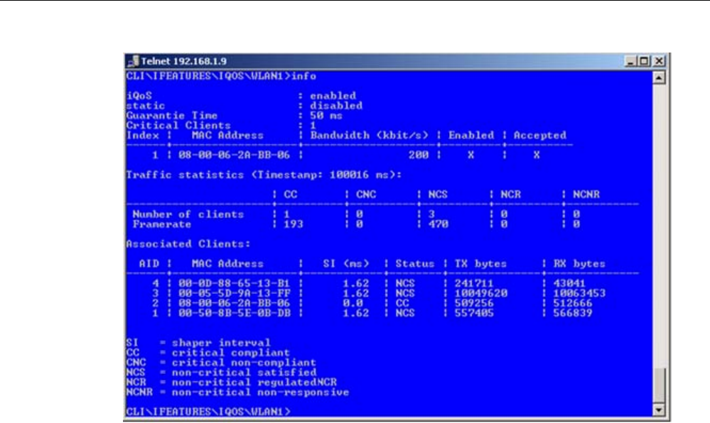
Configuration / project engineering
5.7 Configuration with the Command Line Interface
SCALANCE W786-xPRO
Operating Instructions, Release 08/2007, C79000-G8976-C221-02 213
The "Traffic statistics" table shows how many clients are currently in each status and how
many packets of a particular class were sent for each of these classes.
The "Associated Clients" table provides an overview of all clients, their current classification,
and the volume of sent and received data. The shaper interval (SI) is also is displayed for
each client. The shaper interval is the minimum spacing between two packets of a client set
by iQoS. For NCS clients, the SI is selected so that their bandwidth is twice the size of the
current bandwidth.
See also
iQoS menu command (in access point mode only) (Page 153)
iQoS menu command (Page 165)
5.7.7.2 CLI\IFEATURES\FORCED_ROAM\WLAN1 (or \WLAN2 or \WLAN3) menu command
Cyclic connection monitoring of an IP address
With the commands in this menu, you set the properties of the forced roaming mode.

Configuration / project engineering
5.7 Configuration with the Command Line Interface
SCALANCE W786-xPRO
214 Operating Instructions, Release 08/2007, C79000-G8976-C221-02
CLI\IFEATURES\FORCED_ROAM\WLAN1> (or \WLAN2 or \WLAN3)
Comment Command Description
IWLAN/
PB LINK
W744 W746 W747 W78x
W78x
RR
froam [E|D] Enables of disables forced roaming on
IP down.
ᅳ ᅳ ᅳ ᅳ ✔ ✔
ip [IP address] Monitors the connection to this IP
partner.
ᅳ ᅳ ᅳ ᅳ ✔ ✔
interval [100 - 5000] Specifies the monitoring cycles to the
IP partner in milliseconds.
ᅳ ᅳ ᅳ ᅳ ✔ ✔
lostpkts [1 - 5] Specifies the maximum number of
unanswered pings before the WLAN
interface is disabled.
ᅳ ᅳ ᅳ ᅳ ✔ ✔
See also
Forced Roaming on IP Down menu command (in access point mode only) (Page 154)
5.7.7.3 CLI\IFEATURES\LINKCHECK menu command
Device-related connection monitoring
With the commands in this menu, you set the properties of device-related connection
monitoring.
CLI\IFEATURES\LINKCHECK>
Comment Command Description
IWLAN/
PB LINK
W744 W746 W747 W78x
W78x
RR
linkchk [E|D] Enable / disable device-related
connection monitoring.
ᅳ ᅳ ᅳ ᅳ ✔ ✔
add <MAC> [timeout] Adds a new MAC address for
connection monitoring and specifies
the monitoring time. No time is
specified, the default is 500 ms.
ᅳ ᅳ ᅳ ᅳ ✔ ✔
edit <Index|MAC>
[E|D] [timeout] Modifies, enables, or disables an entry. ᅳ ᅳ ᅳ ᅳ ✔ ✔
delete <Index|MAC> Deletes the specified entry from the
list.
ᅳ ᅳ ᅳ ᅳ ✔ ✔
clearall Deletes all entries for connection
monitoring.
ᅳ ᅳ ᅳ ᅳ ✔ ✔
acknow [Index|All] Displays or acknowledges (clears) the
Link Check messages requiring
acknowledgment.
The fault state remains active until all the fault
messages have been acknowledged. The fault
status and the LED are cleared if the reason for
the fault status was only a link check error
message.

Configuration / project engineering
5.7 Configuration with the Command Line Interface
SCALANCE W786-xPRO
Operating Instructions, Release 08/2007, C79000-G8976-C221-02 215
Comment
ᅳ ᅳ ᅳ ᅳ ✔ ✔
See also
Link Check menu command (in access point mode only) (Page 154)
5.7.7.4 CLI\IFEATURES\REDUNDANCY menu command
Redundant connection
With the commands in this menu, you set the properties of the redundant connection
between two devices.
CLI\IFEATURES\REDUNDANCY>
Comment Command Description
IWLAN/
PB LINK
W744 W746 W747 W78x
W78x
RR
redun [E|D] Enables / disables the redundancy
function
ᅳ ᅳ ᅳ ᅳ ✔ ✔
wep [E|D] Enables / disables encryption. ᅳ ᅳ ᅳ ᅳ ✔ ✔
mac1 <MAC address> Specifies the device that will be
operated redundantly along with the
first wireless adapter.
ᅳ ᅳ ᅳ ᅳ ✔ ✔
mac2 <MAC address> Specifies the device that will be
operated redundantly along with the
second wireless adapter.
ᅳ ᅳ ᅳ ᅳ ✔ ✔
name [system name] Instead of the MAC addresses, you
can also specify the sysName of the
device.
ᅳ ᅳ ᅳ ᅳ ✔ ✔
wepkey1 [key index] Specifies the WEP key of the device
that will be operated redundantly along
with the first wireless adapter.
ᅳ ᅳ ᅳ ᅳ ✔ ✔
wepkey2 [key index] Specifies the WEP key of the device
that will be operated redundantly along
with the second wireless adapter.
ᅳ ᅳ ᅳ ᅳ ✔ ✔
See also
Redundancy menu command (in access point mode only) (Page 155)

Configuration / project engineering
5.7 Configuration with the Command Line Interface
SCALANCE W786-xPRO
216 Operating Instructions, Release 08/2007, C79000-G8976-C221-02
5.7.7.5 CLI\IFEATURES\IP_ALIVE menu command
Application-related connection monitoring
With the commands in this menu, you set the properties of application-related connection
monitoring.
CLI\IFEATURES\IP_ALIVE>
Comment Command Description
IWLAN/
PB LINK
W744 W746 W747 W78x
W78x
RR
ipalive <E|D> Enables / disables application-related
connection monitoring.
ᅳ ᅳ ᅳ ᅳ ✔ ✔
add <E|D> <IP address>
<:Port> <Timeout> Adds a new IP address to the
connection monitoring and enables /
disables monitoring for this IP address.
ᅳ ᅳ ᅳ ᅳ ✔ ✔
edit <Index|IP addr.>
[:port] [E|D]
[timeout]
Modifies, enables, or disables the entry
specified by the index or IP address.
ᅳ ᅳ ᅳ ᅳ ✔ ✔
delete <Index|IP addr. Deletes the node to be monitored. ᅳ ᅳ ᅳ ᅳ ✔ ✔
clearall Deletes all entries for connection
monitoring.
ᅳ ᅳ ᅳ ᅳ ✔ ✔
The fault state remains active until all the fault
messages have been acknowledged. The fault
state and the Fault LED are cleared if the only
reason was an IP Alive error message. The
command is not visible in the client mode.
acknow [Index|All] Displays or acknowledges (clears) the
IP Alive messages requiring
acknowledgment.
ᅳ ᅳ ᅳ ᅳ ✔ ✔
See also
IP Alive menu command (in access point mode only) (Page 156)
5.7.8 The CLI\INFORM menu
5.7.8.1 CLI\INFORM menu command
System events and information on the protocols
The pages of this menu provide information on system events and protocols.

Configuration / project engineering
5.7 Configuration with the Command Line Interface
SCALANCE W786-xPRO
Operating Instructions, Release 08/2007, C79000-G8976-C221-02 217
CLI\INFORM>
Comment Command Description
IWLAN/
PB LINK
W744 W746 W747 W78x
W78x
RR
This can be called in every submenu.
info Displays information on the current
menu item. ✔ ✔ ✔ ✔ ✔ ✔
WLAN1 Opens the WLAN menu ✔ ✔ ✔ ✔ ᅳ ᅳ
ETHERNET Opens the ETHERNET menu ᅳ ✔ ✔ ✔ ᅳ ᅳ
LOG Opens the LOG menu ✔ ✔ ✔ ✔ ᅳ ᅳ
AUTHLOG Opens the AUTHLOG menu ✔ ✔ ✔ ✔ ᅳ ᅳ
SIGNAL Open the signal recorder menu ✔ ✔ ✔ ✔ ᅳ ᅳ
spanning Displays information on spanning tree ᅳ ᅳ ᅳ ᅳ ✔ ✔
See also
Information menu command (Page 157)
5.7.8.2 CLI\INFORM\LOG menu command
System events and information on the protocols
The pages of this menu display tables contain information on system events and on the
behavior of the protocols (IP, TCP, UDP, and ICMP, SNMP).
CLI\INFORM\LOG>
Comment Command Description
IWLAN/
PB LINK
W744 W746 W747 W78x
W78x
RR
events <show | clear> Displays or deletes the log table. ✔ ✔ ✔ ✔ ✔ ✔
addevent <Text> Adds an event to the log table. ✔ ✔ ✔ ✔ ✔ ✔
The default is 400.
eventmax [Max count] Sets the maximum number of log
entries. ✔ ✔ ✔ ✔ ✔ ✔
See also
Log Table menu command (Page 157)

Configuration / project engineering
5.7 Configuration with the Command Line Interface
SCALANCE W786-xPRO
218 Operating Instructions, Release 08/2007, C79000-G8976-C221-02
5.7.8.3 CLI\INFORM\AUTHLOG menu command
Logging authentication
The pages of this menu contain a table with information on successful or failed
authentication attempts.
CLI\INFORM\AUTHLOG>
Comment Command Description
IWLAN/
PB LINK
W744 W746 W747 W78x
W78x
RR
Displays the authentication entries. By
specifying a parameter, the display
can be limited to specific information:
0 All
1 Good
2 All Errors
3 802.11 Errors
4 ACL Errors
5 RADIUS Errors
(request denied, password
rejected etc.)
6 802.1x Errors
(timeout, no response from
RADIUS or WPA server)
7 Deauthenticated Errors
show [0...8]
8 Deassociated errors
✔ ✔ ✔ ✔ ✔ ✔
clear Deletes all entries. ✔ ✔ ✔ ✔ ✔ ✔
See also
Auth Log menu command (Page 157)
5.7.8.4 CLI\INFORM\WLAN1 (or \WLAN2 or \WLAN3) menu command
Logged-on clients
All the logged-on clients along with certain additional information (wireless channel, status
etc.) are displayed here.

Configuration / project engineering
5.7 Configuration with the Command Line Interface
SCALANCE W786-xPRO
Operating Instructions, Release 08/2007, C79000-G8976-C221-02 219
CLI\INFORM\WLANx>
Comment Command Description
IWLAN/
PB LINK
W744 W746 W747 W78x
W78x
RR
Station Displays information on the connected
stations.
✔ ✔ ✔ ✔ ✔ ✔
resetStats Resets the statistics that are displayed
with the Station command.
✔ ✔ ✔ ✔ ✔ ✔
(only in access point mode)
Apinfo Displays information on the access
point. ᅳ ᅳ ᅳ ᅳ ✔ ✔
Scan Displays all the access points in the
area. Possible only if iPCF is disabled.
✔ ✔ ✔ ✔ ✔ ✔
Noise Shows disturbances on the individual
channels.
✔ ✔ ✔ ✔ ✔ ✔
stasort Displays information on the available
access points sorted according to MAC
addresses or signal strength.
✔ ✔ ✔ ✔ ᅳ ᅳ
scanww Displays all access points regardless
of the country code.
ᅳ ✔ ✔ ✔ ✔ ✔
vap Displays all configured SSIDs (VAPs). ᅳ ᅳ ᅳ ᅳ ✔ ✔
overlap Shows the access points on the set or
adjacent channels.
ᅳ ᅳ ᅳ ᅳ ✔ ✔
over_age [1..7200] Changes the aging interval (in
minutes) for the list of neighboring
access points. If an AP is inactive for
longer than the time set here, it is
removed from the list.
ᅳ ᅳ ᅳ ᅳ ✔ ✔
See also
Client List menu command (Page 159)
5.7.8.5 CLI\INFORM\SIGNAL menu command
Display of the current signal strength and recording of a series of measurements
With the commands in this menu, you set the properties of the signal recorder.
CLI\INFORM\SIGNAL>
Comment Command Description
IWLAN/
PB LINK
W744 W746 W747 W78x
W78x
RR
recstart <interval>
[number of recording
points]
Starts signal recording. This command is only available in the client
mode.

Configuration / project engineering
5.7 Configuration with the Command Line Interface
SCALANCE W786-xPRO
220 Operating Instructions, Release 08/2007, C79000-G8976-C221-02
Comment
The interval at which the current signal
is recorded can be between 1 and
1000 milliseconds.
A value between 1 and 20000 is
possible for the number of recording
points.
✔ ✔ ✔ ✔ ✔ ✔
This command is only available in the client
mode.
recstop Stops signal recording prematurely.
✔ ✔ ✔ ✔ ✔ ✔
This command is only available in the client
mode.
dispstart [interval] Displays the current signal strength
cyclically on the CLI.
The interval can be between 100 and
10000 milliseconds
✔ ✔ ✔ ✔ ✔ ✔
This command is only available in the client
mode.
dispstop Stars cyclic output of the signal
strength.
✔ ✔ ✔ ✔ ✔ ✔
This command is only available in client mode
exit Closes the CLI/TELNET connection.
✔ ✔ ✔ ✔ ✔ ✔
This command is only available in client mode
info Displays the parameters of the signal
recorder ✔ ✔ ✔ ✔ ✔ ✔
See also
Signal Recorder menu command (Page 167)

Configuration / project engineering
5.8 Configuring with the PRESET PLUG
SCALANCE W786-xPRO
Operating Instructions, Release 08/2007, C79000-G8976-C221-02 221
5.8 Configuring with the PRESET PLUG
5.8.1 How the PRESET-PLUG works
Multiple use of configuration data
The PRESET PLUG is an extremely simple way of assigning a configuration to several
identically configured SCALANCE W786 devices. You transfer an existing configuration to
any number of other devices using the PRESET PLUG. This procedure is particularly useful
when commissioning a lot of WLAN clients with the same parameter settings because you
do not need to set parameters for each client manually.
Note
To avoid duplicating IP addresses, the IP parameters are not changed but are retained when
you use the PRESET PLUG.
If the PRESET PLUG is inserted, the WLAN interface of the device is deactivated. WLAN
operation with a PRESET PLUG insert it is not possible.
5.8.2 Creating a Configuration with a new PRESET PLUG
Procedure
Follow the steps below to save a configuration on a PRESET PLUG:
1. Insert the PRESET PLUG in the C-PLUG slot of a powered-down device with the required
configuration and then turn on the device.
2. Start Web Based Management and select the System > C-PLUG menu.
3. In the "Modify C-PLUG" drop-down list box, select the "Create PRESET-PLUG" entry.
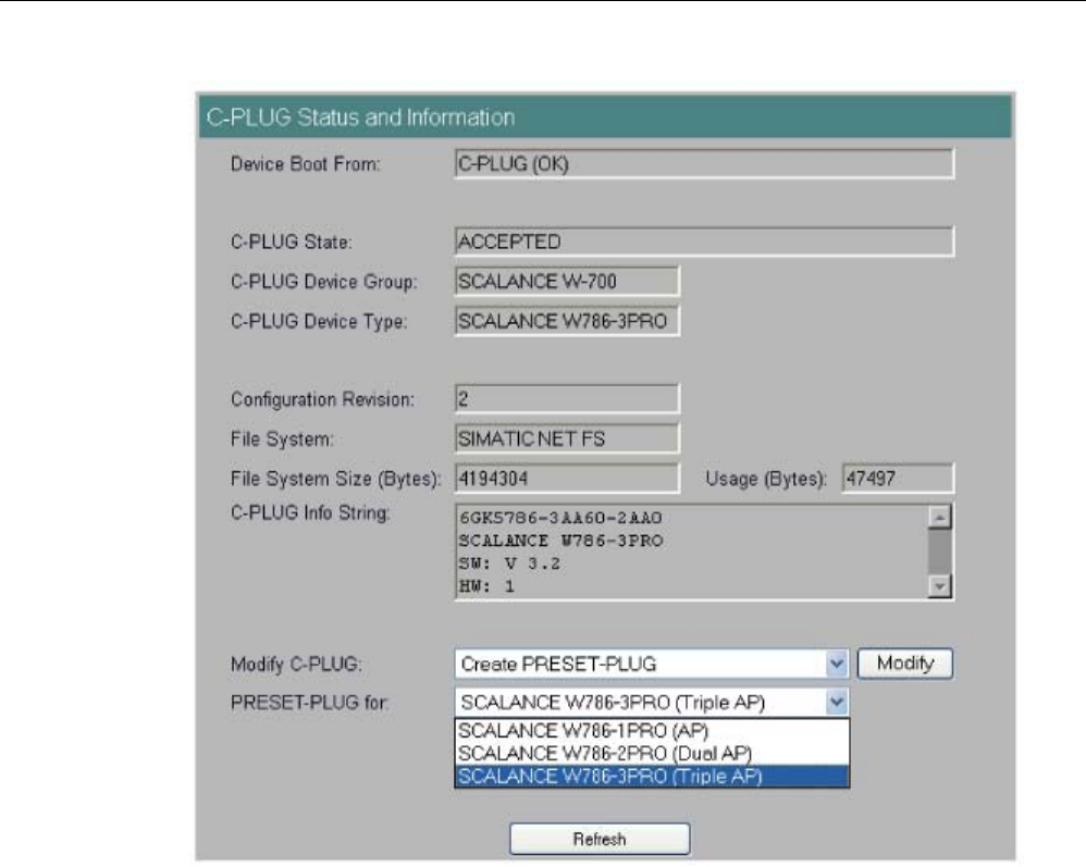
Configuration / project engineering
5.8 Configuring with the PRESET PLUG
SCALANCE W786-xPRO
222 Operating Instructions, Release 08/2007, C79000-G8976-C221-02
4. In the "PRESET PLUG for" box, specify the device for which you want to create the
PRESET PLUG. The PRESET-PLUG created in this way functions only with the device
type you selected. The figure above shows an example of the possible selections for a
SCALANCE W786.
5. Click on the "Modify" button to transfer the configuration of the device to the PRESET
PLUG.
6. Turn the device off and remove the PRESET PLUG.
5.8.3 Changing a PRESET PLUG that already contains configuration data
Procedure
Follow the steps below to change the configuration data on a PRESET PLUG:
1. Insert the PRESET PLUG in the C-PLUG slot of a powered-down SCALANCE W-700 and
then turn on the device. The P1 and R1 LEDs flash yellow to signal that the PRESET
PLUG was detected.

Configuration / project engineering
5.8 Configuring with the PRESET PLUG
SCALANCE W786-xPRO
Operating Instructions, Release 08/2007, C79000-G8976-C221-02 223
2. Start Web Based Management; there you will see the current settings of the PRESET
PLUG.
3. Make the required changes to the configuration.
4. In the "Modify C-PLUG" drop-down list box, select the "Create PRESET-PLUG" entry.
5. In the "PRESET PLUG for" box, specify the device for which you want to create the
PRESET PLUG.
6. Click the "Modify" button to transfer the configuration of the device to the PRESET PLUG.
7. Turn the device off and remove the PRESET PLUG.
5.8.4 Putting a device into operation with a PRESET PLUG
Procedure
Note
To work correctly, the PRESET PLUG must have a content that matches the target device.
Follow the steps below to put a device into operation with the configuration data on a
PRESET PLUG.
1. Insert the PRESET PLUG in the C-PLUG slot of the device to which you want to assign a
configuration.
2. Turn on the power to the device. The LEDs "P1" and "R1" (and "Rx" on a SCALANCE W-
700 with more than one wireless interface) flash yellow to signal that the PRESET PLUG
was detected.
3. Press the reset button beside the C-PLUG briefly to save the settings of the PRESET
PLUG on the device.
4. When all the data has been transferred from the PRESET PLUG to the device, the LEDs
stop flashing and are permanently lit.
5. Turn the device off and remove the PRESET PLUG.
Note
The next time the device starts up, it uses the settings from the PRESET PLUG and the
previous IP configuration.
SCALANCE W786-xPRO
Operating Instructions, Release 08/2007, C79000-G8976-C221-02 225
Upkeep and maintenance 6
6.1 Loading new firmware over FTP
Procedure
You can load new firmware on a SCALANCE W-700 over FTP even if the device is not
reachable over WEB Based Management or the CLI. This may be the situation if there was a
power down during a firmware update. Follow the steps below to load new firmware using
FTP:
1. Turn off the power to the device.
2. Now press the Reset button and reconnect the power to the device while holding down
the button.
3. Hold down the button until the red fault LED (F) starts to flash after approximately 2
seconds.
4. Now release the button. The bootloader waits in this state for a new firmware file that you
can download by FTP.
5. Connect a PC to the SCALANCE W-700 over the Ethernet interface.
6. Assign an IP address to the SCALANCE W-700 with the Primary Setup Tool.
7. Open a DOS box and change to the directory where the file with the new firmware is
located and then execute the command "ftp <ip address>".
As an alternative, you can use a different FTP client.
8. Enter "siemens" as both the login and password.
9. Load the new firmware with the command "put <firmware>".
10. Once the firmware has been transferred completely to the device, the device is restarted
automatically.

Upkeep and maintenance
6.2 Restoring the default parameter settings
SCALANCE W786-xPRO
226 Operating Instructions, Release 08/2007, C79000-G8976-C221-02
6.2 Restoring the default parameter settings
Procedure
Follow the steps below to reset the device parameters to the factory settings:
NOTICE
When you reset the device parameters, all previously changed settings are lost!
1. Turn off the power to the device.
2. Now press the Reset button and reconnect the power to the device while holding down
the button.
3. Hold down the button until the red fault LED (F) stops flashing after approximately 10
seconds and is permanently lit.
4. Now release the button and wait until the fault LED (F) goes off again.
5. The device then starts automatically with the default parameters.

SCALANCE W786-xPRO
Operating Instructions, Release 08/2007, C79000-G8976-C221-02 227
Technical specifications 7
7.1 SCALANCE W786 technical specifications
Product versions
● SCALANCE W786-1PRO with one wireless interface and in the variants with two internal
antennas or two external antenna connectors and with RJ-45 or FO connector
● SCALANCE W786-2PRO with two wireless interfaces and in the variants with four
internal antennas or four external antenna connectors and with RJ-45 or FO connector
● SCALANCE W786-3PRO with three wireless interfaces and in the variants with six
external antenna connectors and with RJ-45 or with FO connector
Data transfer
Ethernet transfer rate 10/100 Mbps
Wireless transmission rate 1 ... 54 Mbps (108 Mbps)
Wireless standards supported 802.11a
802.11b
802.11g
802.11h
Power supply standards supported 802.3af (Power over Ethernet)
Interfaces
Power • 48 V DC supply via supplied connector
• RJ-45 jack Power over Ethernet
(48 V DC)
• 2 x 12 - 24 V DC supplies with optional power
supply adapter (available as accessory)
• 110 - 230 V AC with optional power supply
adapter (available as accessory)
Power supply isolated according to IEEE 802.3af,
isolation resistance > 2 Mohms.

Technical specifications
7.1 SCALANCE W786 technical specifications
SCALANCE W786-xPRO
228 Operating Instructions, Release 08/2007, C79000-G8976-C221-02
Data • RJ-45 jack for Ethernet
or on devices for FO cable:
1 x 2 BFOC sockets
• depending on version, up to six R-SMA antenna
sockets
Electrical data
PoE 12.9 W
48 V DC 12.9 W
12 - 24 V DC (adapter) 15 W
Power consumption depending on power supply
110 - 230 V AC
(adapter)
15 W
Construction
Dimensions
(W x H x D)
251 mm x 251 mm x 72 mm
Without power supply
adapter
2241 g
With power supply
adapter 12 - 24 V DC
2428 g
Weight
(version with three IWLAN ports)
With power supply
adapter
110 - 230 V AC
2433 g
Permitted ambient conditions
Operating temperature -40°C to 70°C
Transport/storage temperature -40°C to 85°C
Degree of protection Tested to IP65
MTBF information (mean time between failure)
MTBF 61 years

Technical specifications
7.1 SCALANCE W786 technical specifications
SCALANCE W786-xPRO
Operating Instructions, Release 08/2007, C79000-G8976-C221-02 229
Specifications and order numbers
Type Number of
WLAN ports
Number and
type of
Ethernet ports
Number of
internal
antennas
Number of R-
SMA sockets
for external
antennas
Order No.
W786-1PRO 1 1 RJ-45 1
(diversity(2))
— 6GK5786-
1BA60-2AA0
6GK5786-
1BA60-2AB0
(1)
W786-1PRO 1 1 RJ-45 — 2 6GK5786-
1AA60-2AA0
6GK5786-
1AA60-2AB0
(1)
W786-1PRO 1 1 ST duplex
multimode FO
cable
1
(diversity(2))
— 6GK5786-
1BB60-2AA0
6GK5786-
1BB60-2AB0
(1)
W786-1PRO 1 1 ST duplex
multimode FO
cable
— 2 6GK5786-
1AB60-2AA0
6GK5786-
1AB60-2AB0
(1)
W786-2PRO 2 1 RJ-45 2
(diversity(2))
— 6GK5786-
2BA60-2AA0
6GK5786-
2BA60-2AB0
(1)
W786-2PRO 2 1 RJ-45 — 4 6GK5786-
2AA60-2AA0
6GK5786-
2AA60-2AB0
(1)
W786-2PRO 2 1 ST duplex
multimode FO
cable
2
(diversity(2))
— 6GK5786-
2BB60-2AA0
6GK5786-
2BB60-2AB0
(1)
W786-2PRO 2 1 ST duplex
multimode FO
cable
— 4 6GK5786-
2AB60-2AA0
6GK5786-
2AB60-2AB0
(1)
W786-3PRO 3 1 RJ-45 — 6 6GK5786-
3AA60-2AA0
6GK5786-
3AA60-2AB0
(1)

Technical specifications
7.1 SCALANCE W786 technical specifications
SCALANCE W786-xPRO
230 Operating Instructions, Release 08/2007, C79000-G8976-C221-02
Type Number of
WLAN ports
Number and
type of
Ethernet ports
Number of
internal
antennas
Number of R-
SMA sockets
for external
antennas
Order No.
W786-3PRO 3 1 ST duplex
multimode FO
cable
— 6 6GK5786-
3AB60-2AA0
6GK5786-
3AB60-2AB0
(1)
(1) US variant
(2) There are two internal antennas per WLAN port. The antenna used is always the one that
provides the best possible data transmission (diversity).

SCALANCE W786-xPRO
Operating Instructions, Release 08/2007, C79000-G8976-C221-02 231
Appendix A
A.1 Private MIB variables of the SCALANCE W78x / W74x
Downloading the MIB of the SCALANCE W-700 using the Internet Explorer
Using the URL
http://<IP_address>/snScalanceW.mib
, you display the login window if you are not yet logged on. After you have logged on
successfully, you can access the private MIB of the SCALANCE W-700. To save this on your
PC, the source text view should be enabled.
OID
The private MIB variables of the SCALANCE W78x have the following object identifiers:
iso(1).org(3).dod(6).internet(1).private(4).
enterprises(1).ad(4196).adProductMibs(1).simaticNet(1).
iScalanceW(4)
Variables for access points and clients
The following table shows the private MIB variables available for access points and clients:
Name OID Description Number of
objects
snDownload 1.3.6.1.4.1.4196.1.1.4.100.1.5 Download information and control variables
for image, configuration file, events table.
17
snNvLog 1.3.6.1.4.1.4196.1.1.4.100.1.6 Log for events. 8
snTrapInfo 1.3.6.1.4.1.4196.1.1.4.100.1.7 Information on traps. 6
snGen 1.3.6.1.4.1.4196.1.1.4.100.1.8 General information, not conforming with
MIB-2.
23
snTcpip 1.3.6.1.4.1.4196.1.1.4.100.1.10 IP address, Subnet Mask, Default Gateway,
DHCP Status…
5
snScalanceWCommon 1.3.6.1.4.1.4196.1.1.4.100.2.1 SCALANCE W-700 - specific settings. 24
snScalanceWFilter 1.3.6.1.4.1.4196.1.1.4.100.2.4 Protocol filters and storm threshold settings 18
snScalanceWStats 1.3.6.1.4.1.4196.1.1.4.100.2.5 Information on WLAN 1 and WLAN 2
interfaces.
62
snScalanceWDevices 1.3.6.1.4.1.4196.1.1.4.100.2.6 AP mode: List and information on all clients
currently "associated" or connected.
Client mode: List of devices with which the
client is currently connected.
49

Appendix
A.1 Private MIB variables of the SCALANCE W78x / W74x
SCALANCE W786-xPRO
232 Operating Instructions, Release 08/2007, C79000-G8976-C221-02
Name OID Description Number of
objects
snScalanceWScan 1.3.6.1.4.1.4196.1.1.4.100.2.7 Client mode: List of reachable WLANs and
information whether the clients can connect
to them.
11
snScalanceWAccess 1.3.6.1.4.1.4196.1.1.4.100.2.9 List of IP addresses that can access the
management interface.
5
Variables available only for access points
Name OID Description Number of
objects
snScalanceWAcl 1.3.6.1.4.1.4196.1.1.4.100.2.8 Information and settings for the Access
Control Lists.
9
snScalanceWVirtualAp 1.3.6.1.4.1.4196.1.1.4.100.2.10 Information on the currently configured
virtual APs.
17
Traps for access points and clients
Name Specific
index
Variables Description
snScalanceWPowerLineD
own
32 snScalanceWChangedPowerLine - The power
line where the last power down occurred. 1-
M12, 2-Ethernet Power
This is generated if there is a
power down on M12 or the
Ethernet power connector.
snScalanceWPowerLineU
p
32 snScalanceWChangedPowerLine - The power
line where the last power up occurred. 1-M12,
2-Ethernet Power
This is generated if there is a
power up on M12 or the Ethernet
power connector.
snScalanceWFault 41 snScalanceWFaultValue -
Fault value:
0 = no fault,
bit 0 = power M12 is off,
bit 1 = link down,
bit 2 = internal error,
bit 23 = Link Check error,
bit 24 = IP Alive broken,
bit 25 = power ethernet is off,
bit 26 = Cold/warm start,
bit 27 = C-PLUG error,
bit 28 = iQoS error,
bit 29 = Redundancy error"
This is generated if the
snScalanceWFaultValue variable
is changed.
The bit is set to "1" according to
the event that has occurred.
snScalanceWIQOS 51 snScalanceWIQOSValue - Description of the
last snScalanceWIQOS trap
snScalanceWLinkCheckO
ff
81 snScalanceWLinkCheckValue - Description of
the last snScalanceWLinkCheckOff Trap
This is generated if a timeout
occurs with a client monitored
with Link Check.

Appendix
A.1 Private MIB variables of the SCALANCE W78x / W74x
SCALANCE W786-xPRO
Operating Instructions, Release 08/2007, C79000-G8976-C221-02 233
Name Specific
index
Variables Description
snScalanceWLinkIntegrity
On
82 snScalanceWLinkCheckValue - Description of
the last snScalanceWLinkCheckOn trap
This is generated if a client
monitored with Link Check logs
on again at the AP following a
timeout.
snScalanceWClientAuthe
nticated
85 SnScalanceWClientsIndex - An index of the
client in the snScalanceWClients table
This is generated when a client
logs on at the AP.
snScalanceWClientDeAut
henticated
86 SnScalanceWClientsIndex - An index of the
client in the snScalanceWClients table
This is generated when a client
logs off from the AP.
snScalanceWRedundanc
y
53 SnScalanceWRedundancyValue- Description
of the last redundancy trap.
SnScalanceWRedundancyState- Status of
redundancy connection
This is generated if the status of
the redundant connection
changes, for example when the
connection of wireless interface A
aborts.
Traps available only for access points
Name Specific
index
Variables Description
snScalanceWOverlapAP 101 snScalanceWOverlapAPValue
- Description of the last OverlapAP trap.
Is generated when an
access point is detected on the
device's own or an overlapping
wireless channel.
snScalanceWiPCFPNIO
maxSTAs
111 snScalanceWPNIOValue - Description of the
last snScalanceWiPCFPNIOmaxSTAs or
snScalanceWiPCFPNIOCycleTime trap
Is generated when there are too
many clients registered for the
specified update time in iPCF
mode with PNIO support.
snScalanceWiPCFPNIOC
ycleTime
112 snScalanceWPNIOValue - Description of the
last snScalanceWiPCFPNIOmaxSTAs or
snScalanceWiPCFPNIOCycleTime trap
Is generated when the specified
update time in iPCF mode with
PNIO support cannot be kept to.
snScalanceWForcedRoa
mingVapStateChanged
121 snScalanceWVirtualApIndex
- Index of the VAP
snScalanceWVirtualApState
- Current State of the VAP
unknown (0)
authenticated (1)
associated (2)
powersafe (3)
adhoc (4)
joined (5)
vap-is-up (6)
vap-starting (7)
vap-is-down (8)
locked (9)
vap-connected (10)
Generated when the status of the
VAP changes.

Appendix
A.2 Designing and calculating wireless systems (for example RCoax)
SCALANCE W786-xPRO
234 Operating Instructions, Release 08/2007, C79000-G8976-C221-02
A.2 Designing and calculating wireless systems (for example RCoax)
Decibels as a logarithmic unit of measure
In wireless technology, most calculations are made in decibels (dB). Decibel means the
logarithm of a ratio. Formulated mathematically, this can be shown by the following equation:
Decibel value = 10 * log (ratio)
Using sample calculations, the following decibel values are obtained:
Ratio Decibel value
0,001 -30 dB
0,1 -10 dB
0,2 -7 dB
0,4 -4 dB
0,5 -3 dB
1 0 dB
2 3 dB
4 6 dB
As can be seen in the example, halving a value reduces the decibel value by 3 dB. This
remains true regardless of the selected reference variable because only the ratio counts.
Which reference variable is used can be recognized by the additional letters or numbers
following the dimension dB. In acoustics, for example, the threshold of audibility is the
reference variable for a value in dB(A).
Specifying power in dBm
A commonly used reference variable in wireless technology is a power of 1 mW. Power can
then be specified in the decibel milliwatt unit (dBm). The following formula is used:
P [dBm] = 10 * log (P [mW] / 1 mW)
This results in the following power specifications in dBm:
Power value Decibel value
0.5 mW ≈ -3 dBm
1 mW ≈ 0 dBm
2 mW ≈ 3 dBm
4 mW ≈ 6 dBm
10 mW ≈ 10 dBm
100 mW ≈ 20 dBm
200 mW ≈ 23 dBm
1000 mW ≈ 30 dBm

Appendix
A.2 Designing and calculating wireless systems (for example RCoax)
SCALANCE W786-xPRO
Operating Instructions, Release 08/2007, C79000-G8976-C221-02 235
Using power specifications, it is simple to calculate gain and attenuation. To calculate an
entire system, the individual values for gain and attenuation must simply be added.
Transmit power in dBm
The information in the following tables applies to the following SIMATIC NET products:
● Access Point SCALANCE W786-1PRO
● Access Point SCALANCE W786-2PRO
● Access Point SCALANCE W786-3PRO
Table A-1 Transmit power in IEEE 802.11b mode (2.4 GHz)
Data rate [Mbps] P0 [dBm]
1 20
2 20
5,5 20
11 20
Table A-2 Transmit power in IEEE 802.11g mode (2.4 GHz)
Data rate [Mbps] P0 [dBm]
6 20
9 20
12 20
18 20
24 20
36 20
48 20
54 19
Table A-3 Transmit power in IEEE 802.11a/h mode (5 GHz)
Data rate [Mbps] P0 [dBm]
6 20
9 20
12 20
18 20
24 20
36 20
48 20
54 19

Appendix
A.2 Designing and calculating wireless systems (for example RCoax)
SCALANCE W786-xPRO
236 Operating Instructions, Release 08/2007, C79000-G8976-C221-02
Specifying power in dBi
If power is specified in dBi, the reference variable is the transmit power of an isotropic
antenna or unipole. Such a (hypothetical) antenna radiates energy from a central point
uniformly in all directions.
From the directional radiation of a real antenna, a dBi value is obtained known as the
antenna gain. This term is misleading in as far as no energy is gained by an antenna in the
physical sense. The higher radiation of a passive antenna results solely from the
concentration of radiation in a certain direction. In other spatial segments, there is
accordingly less power.
Losses due to longitudinal attenuation
The longitudinal attenuation of the leaky feeder cable depends on its length and is calculated
according to the following formula:
arc = αrc * l
arcLongitudinal attenuation of the cable in dB
αrcAttenuation coefficient in dB/m as specified in the technical specifications of the cable:
RCoax Cable 0.17 dB/m at 2.4 GHz
connecting cable: 0.55 dB/m at 2.4 GHz
l Total length of the cable in m
Losses due to coupling loss
Coupling loss cd includes the losses at the transition from the cable to the surrounding
space. The coupling loss depends on the construction of the cable and its physical
properties. Values for coupling loss are therefore specified for the particular cable in the
technical specifications.
Losses due to spatial attenuation
Spatial attenuation afr specifies the attenuation between the RCoax cable and the
communications partner. The decisive factor here is therefore the distance between the
RCoax cable and communication partner. The following formula is used:
afr = 20 * log(4πd / λ)
afr Spatial attenuation in dB.
d Distance between cable and antenna in m.
λ Wavelength of the electromagnetic oscillation in m; at a frequency of 2.4 GHz, the
wavelength is 0.125 m.
Note
The formula is valid only for the 2.4 GHz RCoax cable.

Appendix
A.2 Designing and calculating wireless systems (for example RCoax)
SCALANCE W786-xPRO
Operating Instructions, Release 08/2007, C79000-G8976-C221-02 237
IEC 61196-4
Values for coupling losses according to IEC 61196-4 already include spatial attenuation of 2
m. To calculate the actual coupling loss, a spatial attenuation for the distance of 2 m must be
deducted from this value. The coupling loss for a specified distance between the RCoax
cable and the antenna of the communication partner is therefore calculated according to the
following formula:
cd = c95 - 20 * log(4π * 2m / λ) + 20 * log(4πd / λ)
cd Coupling loss of the cable in dB for a specified distance between cable and
antenna.
c95c95 value of the coupling loss (specified in the data sheet of the cable)
λ Wavelength of the electromagnetic oscillation in m; at a frequency of 2.4 GHz, the
wavelength is 0.125 m.
d Distance between cable and antenna in m.
For a frequency of 2.4 GHz, you can also calculate with the following equation in which you
must specify the distance d in meters:
cd 2.4 GHz = c95 - 46 dB + 20 * log(100 * d)
For a SIEMENS SIMATIC NET IWLAN RCoax Cable PE 1/2'' 2.4 GHz (c95 = 69 dB at 2.4
GHz), for example, this results in the following coupling losses:
Distance Coupling loss
1 m 63 dB
2 m 69 dB
5 m 77 dB
10 m 83 dB
100 m 103 dB
Note
The formula is valid only for the 2.4 GHz RCoax cable.
Losses due to power splitters
Normally. when a double power splitter is used (one input, two outputs, for example, RCoax
N-Connect Female Power Splitter 2-Way) a loss of 3 dB must be taken into account.
Receiver sensitivity
The receiver sensitivity is the minimum power that must be fed to a receiver to allow
communication to take place. The receiver sensitivity is a device-specific property and
depends on the transmission technique and data rate. The information in the following tables
applies to the following SIMATIC NET products:
● Access Point SCALANCE W786-1PRO

Appendix
A.2 Designing and calculating wireless systems (for example RCoax)
SCALANCE W786-xPRO
238 Operating Instructions, Release 08/2007, C79000-G8976-C221-02
● Access Point SCALANCE W786-2PRO
● Access Point SCALANCE W786-3PRO
Table A-4 Receiver sensitivity in IEEE 802.11b mode (2.4 GHz)
Data rate [Mbps] Pe [dBm]
1 -97
2 -93
5,5 -92
11 -88
Table A-5 Receiver sensitivity in IEEE 802.11g mode (2.4 GHz)
Data rate [Mbps] Pe [dBm]
6 -91
9 -90
12 -89
18 -87
24 -84
36 -80
48 -76
54 -74
Table A-6 Receiver sensitivity in IEEE 802.11a/h mode (5 GHz)
Data rate [Mbps] Pe [dBm]
6 -91
9 -90
12 -90
18 -88
24 -85
36 -82
48 -76
54 -72
72 [*] -76
96 [*] -71
108 [*] -68
[*] Turbo mode

Appendix
A.2 Designing and calculating wireless systems (for example RCoax)
SCALANCE W786-xPRO
Operating Instructions, Release 08/2007, C79000-G8976-C221-02 239
System calculation based on the example of RCoax
The calculation of the entire system shows whether communication is possible at the desired
transmission rate using the desired components. All losses (longitudinal attenuation, spatial
attenuation, power splitters etc.) are deducted from the transmit power. An antenna gain is
added. The result is the power fed to a receiver. This power must be higher than the receiver
sensitivity. The calculation can be made with the following formula:
Pe = P0 - arc - cd - aps + GANT - Δrc - Δfr > Pe min
PeReceiver input power in dBm
P0Transmit power in dBm
arcLongitudinal attenuation of the RCoax cable and the feeder in dB
cdCoupling loss for the distance between RCoax cable and communication
partner
apsPower splitter losses in dB
GANTAntenna gain in dB
ΔrcCorrection value for the longitudinal attenuation in dB. Depending on the concrete
operating conditions, between 5 and 15 dB.
ΔfrCorrection value for the spatial attenuation in dB. Depending on the concrete
operating conditions, between 0 and 20 dB.
Pe minReceiver sensitivity in dBm
SCALANCE W786-xPRO
Operating Instructions, Release 08/2007, C79000-G8976-C221-02 241
Glossary
Access Point
A (Wireless) Access Point (WAP) is an electronic device that functions as the interface
between a mobile wireless network and a wired computer network. End devices (clients)
establish a wireless connection to the wireless access point over a wireless adapter. The
access point is connected to a permanently installed communication network over a cable.
ACL
Access Control List. List with MAC addresses with the right to access the mobile wireless
network.
Ad hoc network
Mobile wireless network between individual devices (point-to-point).
AES
Advanced Encryption Standard, Encryption according to the Rijndael algorithm.
ARP
Address Resolution Protocol
The ARP protocol is used for address resolution. Its task is to find the corresponding network
hardware address (MAC address) for a given protocol address.
An ARP protocol implementation is often found on hosts on which the Internet protocol family
is used. IP forms a virtual network on the basis of IP addresses. These must be mapped to
the given hardware addresses when the data is transported. To achieve this mapping, the
ARP protocol is often used.
Bandwidth
Maximum throughput of a connecting cable (normally specified in bps).
Broadcast
A broadcast is like "calling all all stations": Broadcast packets are received by all nodes
configured to receive broadcasts.

Glossary
SCALANCE W786-xPRO
242 Operating Instructions, Release 08/2007, C79000-G8976-C221-02
Broadcast address
A broadcast in a computer network is a message with which data packets are sent by one
node to all other nodes of a network. If a message is intended for all nodes in a network, a
broadcast address is used as the destination address.
DFS
Dynamic Frequency Selection. With the Dynamic Frequency Selection function, that is also
part of the 802.11h expansion, an automatic channel change is possible if another user or
technical device is discovered on a channel during operation. This includes, for example,
radar systems that also transfer data in the 5 GHz frequency band. Before a channel is used,
it is checked to make sure that no other system is already using the channel or frequency
range. If another user is discovered, data transmission on the channel is stopped and the
device changes to a free channel.
This is intended to avoid influence by WLAN systems operating according to 802.11a in the
5 GHz band.
DHCP
Dynamic Host Configuration Protocol
ESS
Extended Service Set. ESS is a link between two or more cells of a WLAN (BSS - Basic
Service Set) and a larger mobile wireless network.
Firewall
One or more devices that allow or prevent data access to interconnected networks according
to given security restrictions.
Handover
A handover is the procedure in a mobile wireless network (for example a mobile wireless
network complying with IEEE 802.11) during which the mobile client changes from one cell
to another or from one channel to another while a data connection exists.
HTTPS
HyperText Transfer Protocol Secure
Protocol for the encryption and authentication of communication between Web server and
Web browser in the World Wide Web.
HTTPS is an expansion of HTTP for secure transmission of confidential data with the aid of
SSL.
IEEE
Institute of Electrical and Electronics Engineers

Glossary
SCALANCE W786-xPRO
Operating Instructions, Release 08/2007, C79000-G8976-C221-02 243
IEEE 802.11
Standard for mobile wireless networks in the 2.4 GHz range with transmission rates of up to
2 Mbps.
IEEE 802.11a
Standard for mobile wireless networks in the 5 GHz range with transmission rates of up to 54
Mbps.
IEEE 802.11b
Standard for mobile wireless networks in the 2.4 GHz range with transmission rates of up to
11 Mbps.
IEEE 802.11e
Enhancement of the wireless LAN standard to support Quality of Service (QoS).
IEEE 802.11g
Standard for mobile wireless networks in the 2.4 GHz range with transmission rates of up to
54 Mbps.
IEEE 802.11h
The IEEE 802.11a standard expanded by TPC and DFS.
IEEE 802.11i
Among other things, the standard describes the WPA2 method, the TKIP procedure and the
AES encryption algorithm. IEEE 802.11i removes a series of weak points in the WEP
security mechanism.
IEEE 802.1x
The heart of the standard is the use of a Radius server as the authentication server. In
addition to this, in IEEE 802.1x, the entire communication is encrypted.
Industrial Ethernet
A bus system complying with IEEE 802.3 (ISO 8802-2)
IP address
The IP address consists of 4 bytes. Each byte is represented in decimal, with a dot
separating it from the previous one. This results in the following structure, where XXX
represents a number between 0 and 255 (dotted decimal notation): XXX.XXX.XXX.XXX

Glossary
SCALANCE W786-xPRO
244 Operating Instructions, Release 08/2007, C79000-G8976-C221-02
The IP address is made up of two parts, the network ID and the host ID. This allows different
subnets to be created. Depending on the bytes of the IP address used as the network ID and
those used for the host ID, the IP address can be assigned to a specific address class:
Address Class Address class identifier Network address and node
address
O Byte 1 (possible value 1 - 126)
(Byte 1 is the byte furthest left.)
Byte 2 to byte 4
Possible value in each case 0 -
255.
0.0.0 must not be assigned,
255.255.255 is the broadcast
address.
B Byte 1
(possible value 128 - 191)
Byte 2
(possible value 0 - 255)
Byte 3 and byte 4
Possible value in each case 0 -
255.
0.0 must not be assigned,
255,255 is the broadcast
address.
C Byte 1
(possible value 192 - 223)
Bytes 2 and 3
(possible value in each case 0 -
255)
Byte 4
Possible value 1 - 254.
0 must not be assigned, 255 is
the broadcast address.
D Byte 1
(possible value 224 - 239)
multicast addresses
Byte 2 to byte 4
Possible value in each case 0 -
255
0.0.0 must not be assigned.
There are several multicast
addresses with a special
meaning, for example
224.0.0.1
All systems of the subnet
224.0.0.2
All routers of the subnet
iPCF
The industrial Point Coordination Function is a communications protocol with which data
traffic between the access point and connected stations is controlled to avoid collisions.
Using iPCF, the data throughput can be optimized even with a high number of nodes. iPCF
also allows fast cell changes.
PST
Primary Setup Tool
QoS
Quality of Service (QoS) is a general term that indicates the correct functionality of all
interactive components of a telecommunications network. Depending on the communications
standard (for example IP), error parameters are detected and recorded with which the
operation of the technology is continuously monitored and that form the basis for any

Glossary
SCALANCE W786-xPRO
Operating Instructions, Release 08/2007, C79000-G8976-C221-02 245
necessary maintenance. In a general sense, QoS means the quality characteristics of a
network as a whole from the perspective of the user of a particular service.
RADIUS
Remote Authentification Dial In User Service. A method in which the authentication is
handled on a separate server.
Roaming
Free movement of wireless LAN nodes even beyond the boundaries of an access point's
cell. The nodes and can move from one cell to the next without any noticeable interruption.
Server
A server is a device or generally an object that can provide certain services at the request of
a client.
Services
Services provided by a communication protocol.
SINEMA E
The planning, simulation and configuration software SINEMA E is used to plan and configure
IWLAN applications. It can be used to visualize IWLAN networks, for example according to
coverage, data transfer rate, signal/noise ratio and overlapping taking into account
environmental and device characteristics.
SNMP
Simple Network Management Protocol. Standardized protocol for exchange of network
management information.
SSID
The Service Set Identifier (SSID) is used to identify a mobile wireless network based on
IEEE 802.11.
Subnet mask
The subnet mask specifies which parts of an IP address are assigned to the network
number. The bits in the IP address whose corresponding bits in the subnet mask have the
value 1 are assigned to the network number.

Glossary
SCALANCE W786-xPRO
246 Operating Instructions, Release 08/2007, C79000-G8976-C221-02
System
All the electrical equipment within a system. A system includes, among other things:
Programmable logic controllers, devices for operator control and monitoring, bus systems,
field devices, drives, power supply cabling.
TCP/IP
TCP = Transport Connection Protocol; IP = Internet Protocol
TKIP
Temporal Key Integrity Protocol. Scheme for cyclic changing of keys in WLANs.
TPC
The Transmit-Power Control function (TPC) introduced as a supplementary function by the
802.11h enhancement for 5 GHz components allows an automatic adaptation of the transmit
power. Information on the attenuation values and the expected budget reserves in received
power are taken into account. TPC is also intended to make sure that the maximum
permitted transmit power of a channel specified by the relevant regulatory bodies is not
exceeded by the component. TPC attempts to operate with the minimum transmit power
between the communicating stations or between access point and station.
WBM
Web Based Management. HTTP-based configuration method in which an HTTP server is
used in the relevant device.
WDS
Wireless Distribution System. Radio links for connecting the access points for an extended
service set (ESS)
WEP
Wired Eqivalence Privacy is an optional part of the IEEE 802.11 standard. WEP specifies
methods of authentication and encryption working with fixed keys stored on the device. All
devices that want to access a network in which WEP is used must first be supplied with the
same keys. The keys can also only be renewed manually.
Wi-Fi
Wireless Fidelity. Specification for wireless networks.
The Wi-Fi Alliance is a group of WLAN manufacturers that tests and certifies the
interoperability of WLAN products. Wi-Fi is a certification of WLANs according to 802.11b
and is performed by WECA, the WiFi parent organization. This certification confirms the
interoperability of WLAN products operating in compliance to the 802.11b standard.
The Wi-Fi Alliance also develops standards. The WiFi Alliance has developed its own
architectures for security procedures that have not yet been standardized such as the WiFi

Glossary
SCALANCE W786-xPRO
Operating Instructions, Release 08/2007, C79000-G8976-C221-02 247
Protected Architecture (WPA) to be able to test the compatibility of the various
manufacturers' products.
For real-time transmission, the Wi-Fi Alliance has specified Wi-Fi Multimedia (WMM) for
transmissions with guaranteed quality of service (QoS).
WPA
Wi-Fi Protected Access is a method specified by the die Wi-Fi alliance to close the security
gaps in WEP. Authentication using a server is stipulated (802.1x). The dynamic exchange of
keys at each frame introduces further security. Users can choose between TKIP (Temporal
Key Integrity Protocol) and AES (Advanced Encryption Standard).
Although WPA was never officially part of the IEEE 802.11 standards family, it has become
very widespread in a very short time. This, however, applies only to the WPA procedure
described above using TKIP. The optional possible implementation of WPA on the basis of
AES, on the other hand, did not become established and is therefore irrelevant in everyday
practice. AES only took on practical value only with the development of the later WPA2
standard.
WPA-PSK
WPA-PSK is a weakened form of WPA. In this method, authentication is not established by a
server but is based on a password. This password must be configured manually on the client
and server. Wherever possible, you should change to the WPA method to achieve greater
security.
SCALANCE W786-xPRO
Operating Instructions, Release 08/2007, C79000-G8976-C221-02 249
Index
A
ACL, 128
Ad hoc networks, 14
Adopt MAC Address, 76
Antenna Gain, 117
Antennas, 117
ARP table, 139
Authentication, 89, 123
B
Bandwidth reservation, 62, 152
Basic Wizard, 70
Beacons, 116
Bridge priority, 61
C
CLI commands
Shortcuts for commands, 173
Symbolic representation, 173
CostCost, 143
C-PLUG, 26, 108
D
DHCP server, 100
E
Earthing, 46
E-mail, 103
Encryption, 124
F
FAULT, 185
Fault State, 106
Forward Delay, 142
H
Hello time, 142
Help function, 97
HTTPS, 69
I
IEEE 802.11, 20
IEEE 802.11a, 20
IEEE 802.11b, 20
IEEE 802.11g, 20, 120
IP address, 72
IP, TCP/IP, ICMP, SNMP, 166
iPCF Wizard, 70
L
Learning Table, 139
LED simulation, 98
Lightning protection, 45
Link Check, 154
Load & Save, 106
Locale setting, 174
M
MAC filter, 151
Max Age, 142
Mode and locale setting, 98
Multichannel configuration, 16
N
NAPT, 147
NAT, 146
NEW, 97
O
Overlap AP, 163

Index
SCALANCE W786-xPRO
250 Operating Instructions, Release 08/2007, C79000-G8976-C221-02
P
Password
Character set, 82
PRESET PLUG, 221
Priority, 143
Protocol filter, 151
R
RADIUS, 94
Receiver sensitivity, 237
Redundant connection, 62
Refresh, 97
Reset Statistics, 97
RFC
RFC 1518, 65
RFC 1519, 65
Root bridge, 61
RTS/CTS, 116, 118
S
Safety extra low voltage, 46
Save
Device data, 106
Security settings, 85
Security Wizard, 70
Set Values, 97
SNTP, 106, 184
Spanning Tree, 140
Spanning tree port parameters, 142
SSID, 86
Standalone configuration, 13
Storm threshold, 146
Subnet mask, 65
T
Transmit power, 115
TTL, 100
W
WDS, 131
Web Based Management, 68
Wireless access, 15
Wizards, 68
WPA, 125
WPA2, 92