Siemens MSN1V1 Industrial WLAN Access Point User Manual SCALANCE W774 1 W734 1
Siemens AG Industrial WLAN Access Point SCALANCE W774 1 W734 1
Siemens >
Contents
- 1. User Manual
- 2. Installation Guide
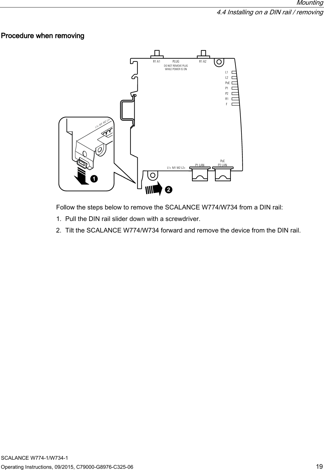
- 3. Operating Instructions
- 4. Reference Manual
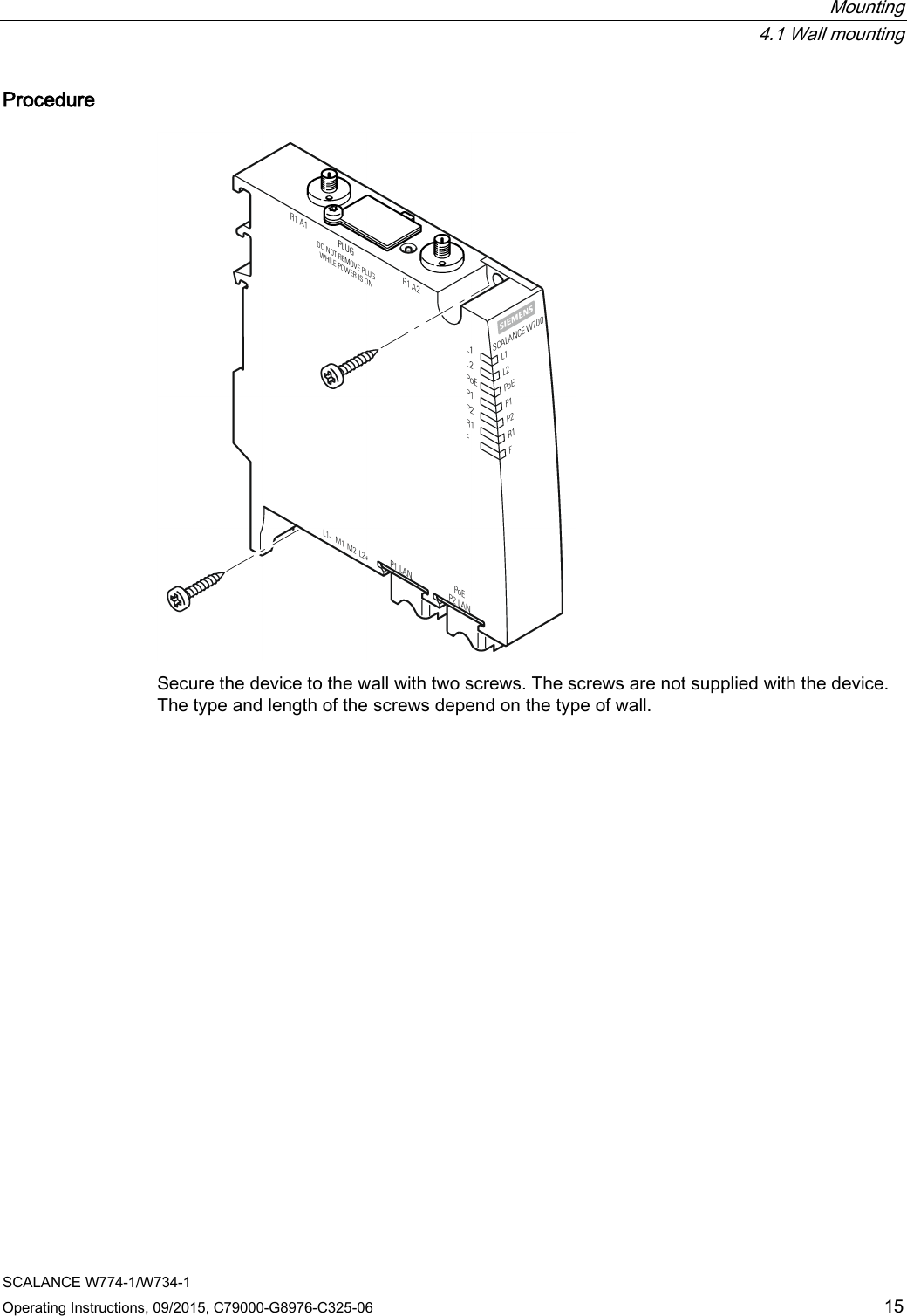
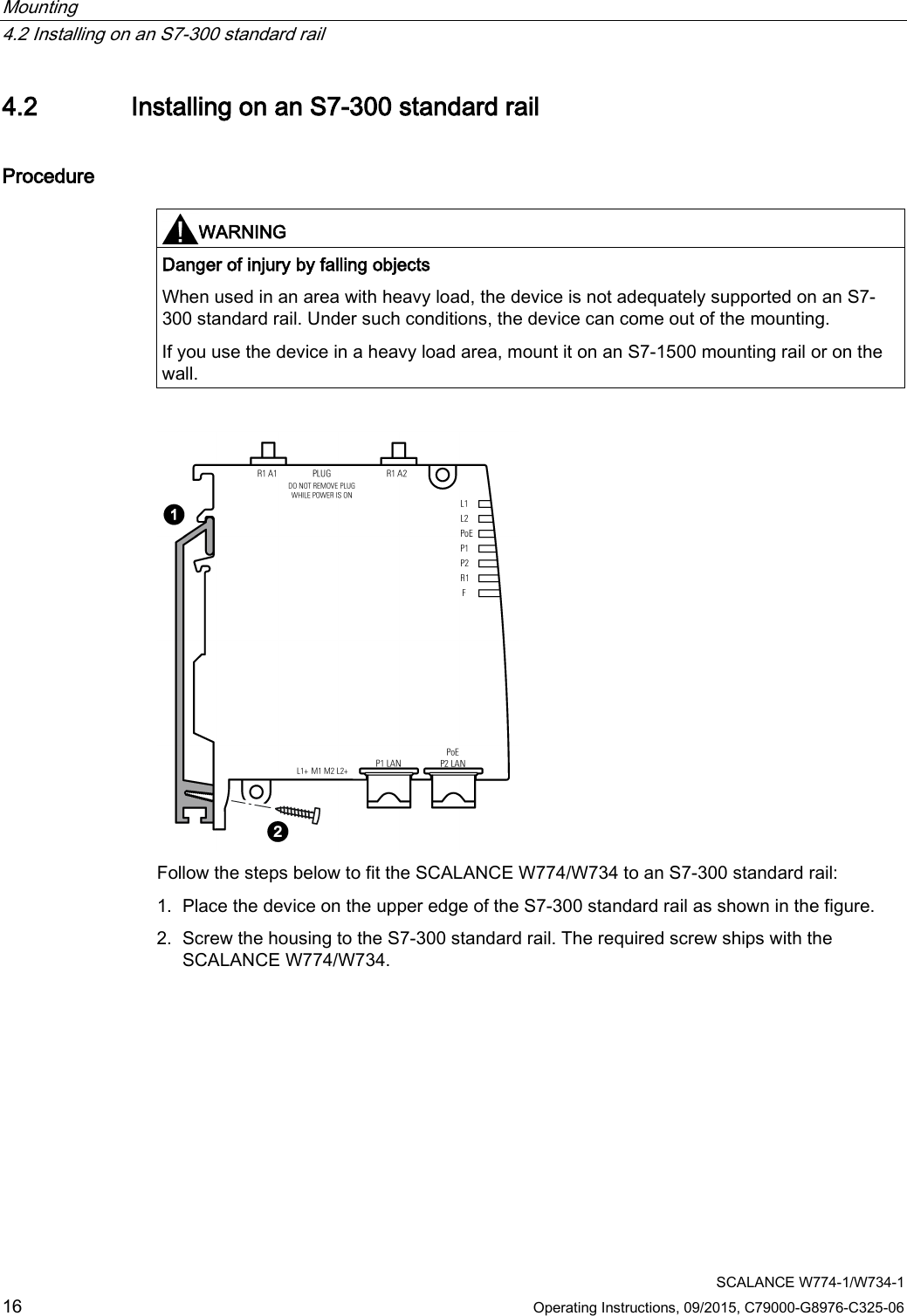
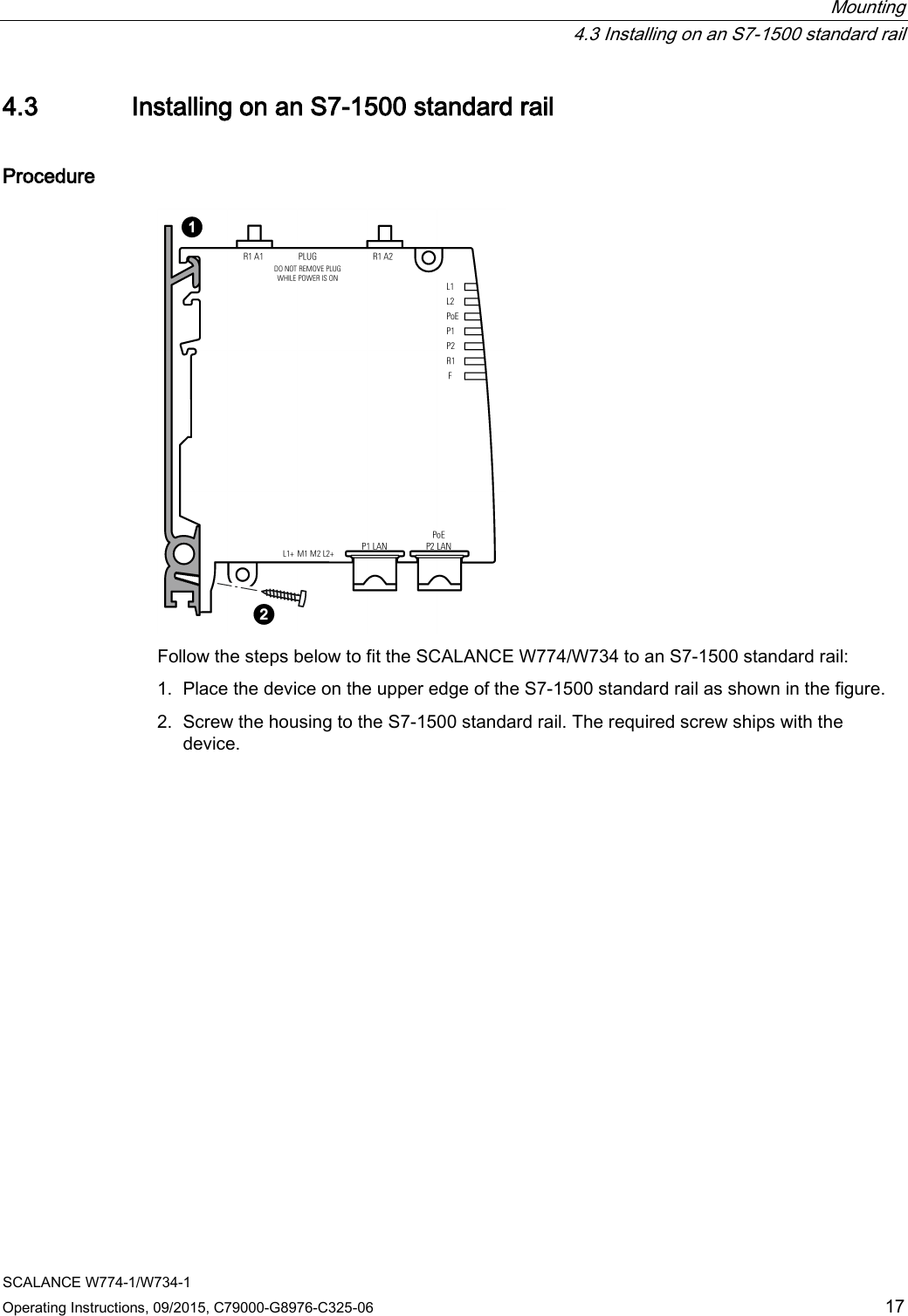
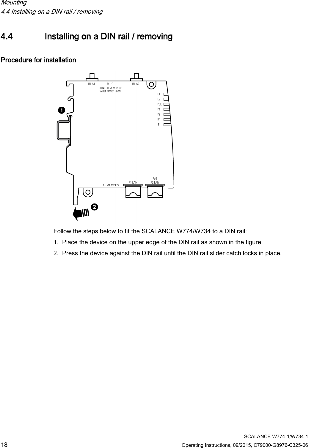
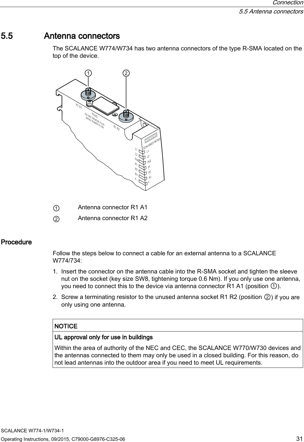
Operating Instructions