Siemens MSN1V1 Industrial WLAN Access Point User Manual SCALANCE W774 1 W734 1
Siemens AG Industrial WLAN Access Point SCALANCE W774 1 W734 1
UserManual.wiki
>
Siemens
>
MSN1V1 User Manual
>
User Manual
Contents
1.
User Manual
2.
Installation Guide
3.
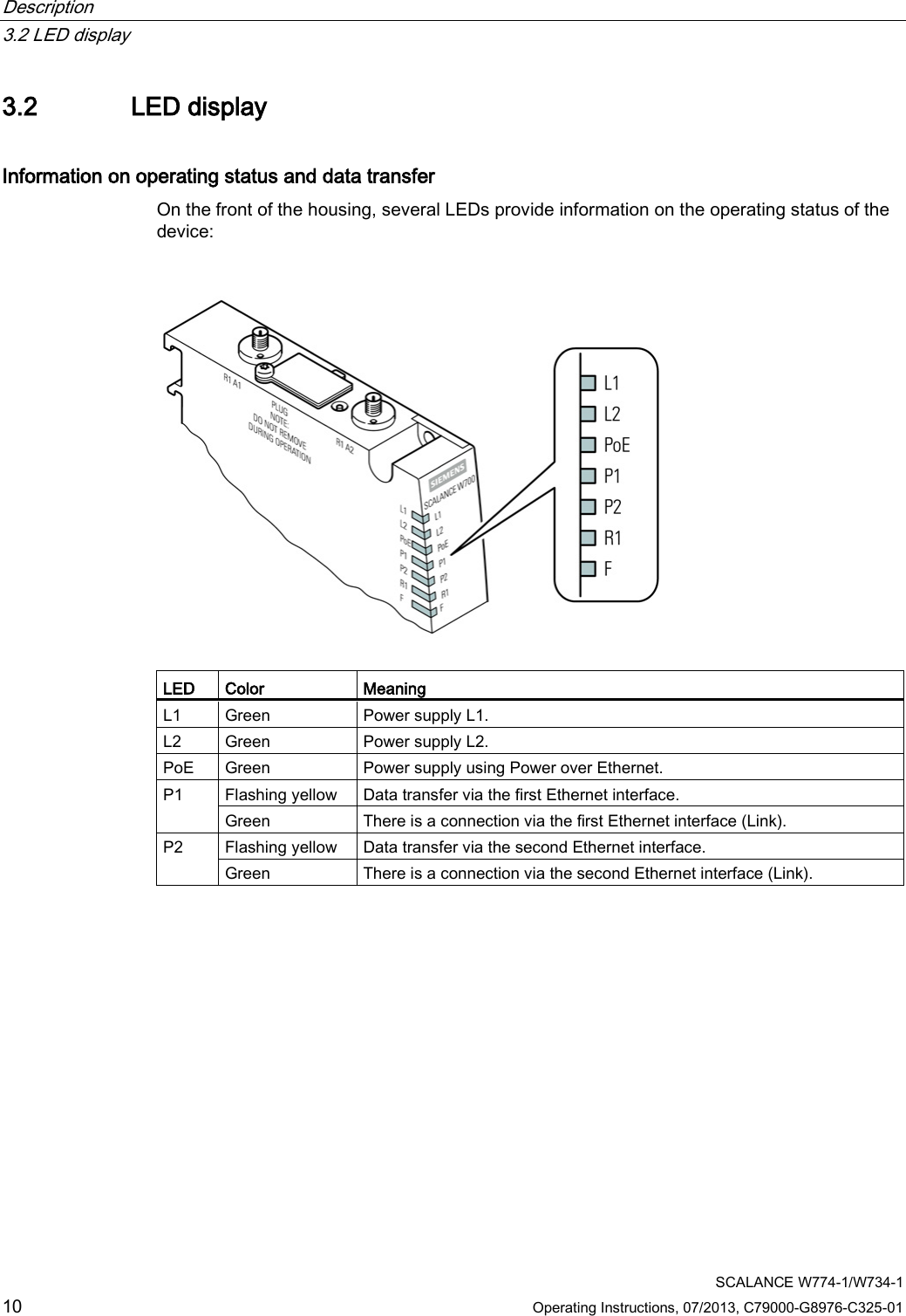
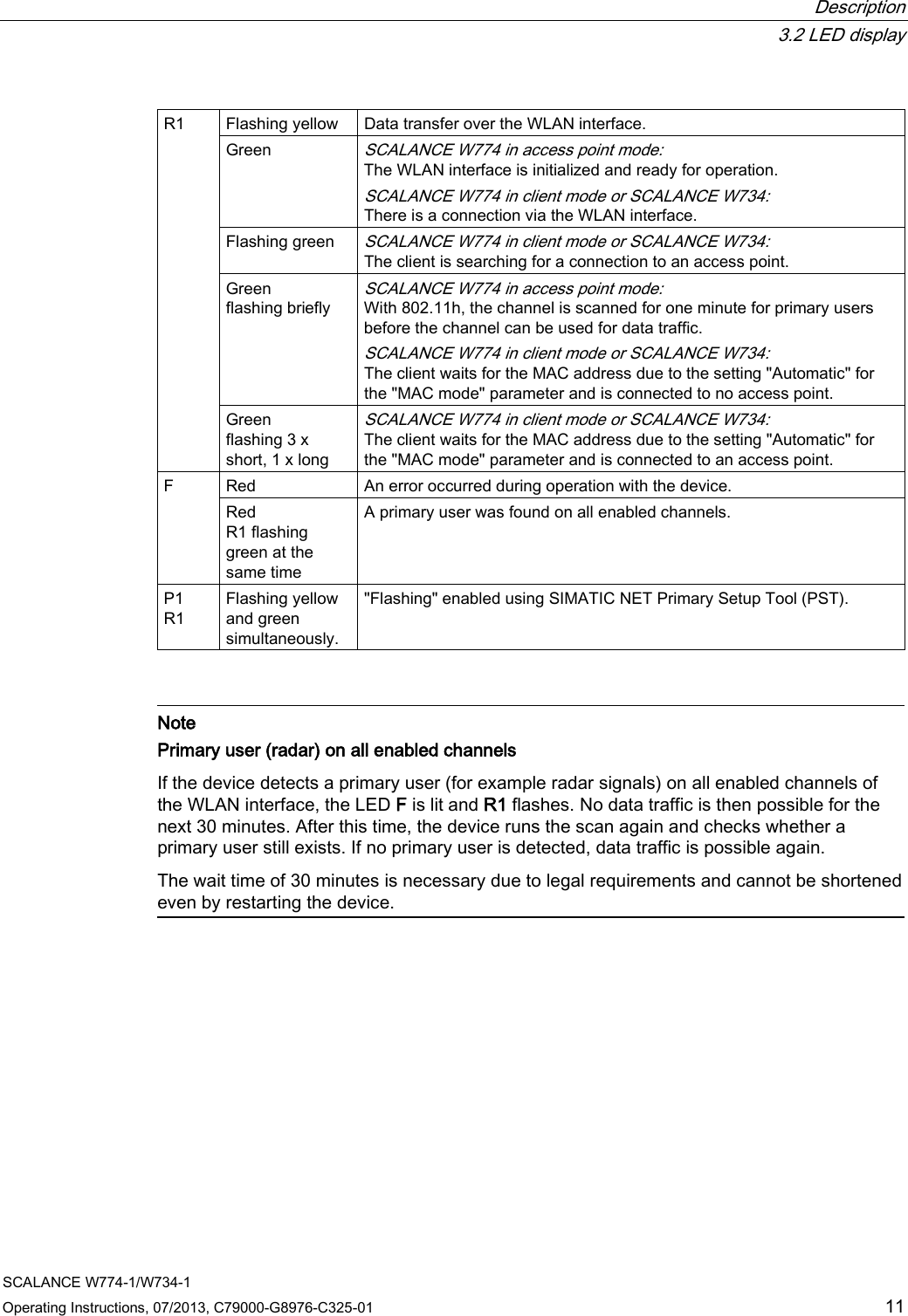
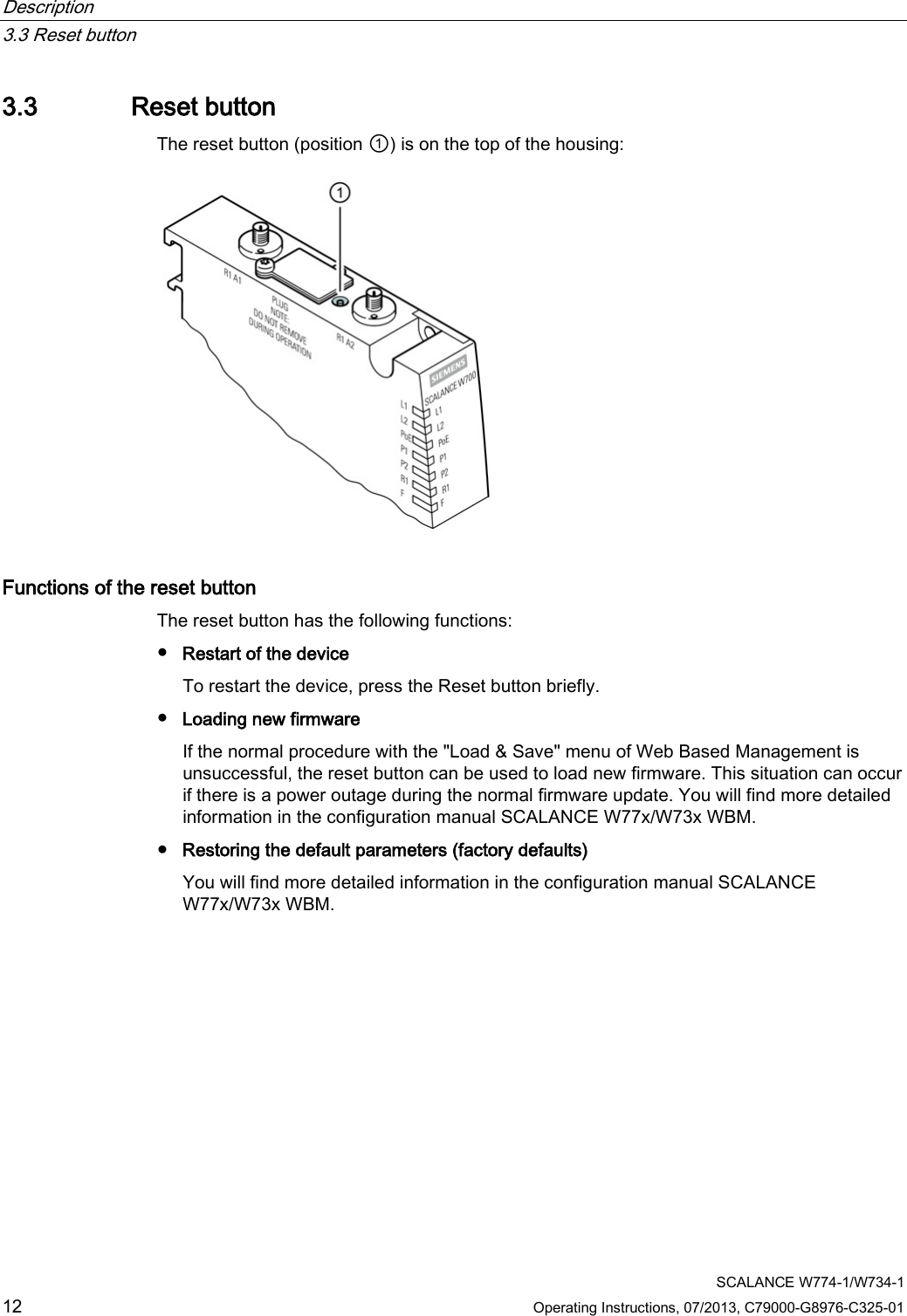
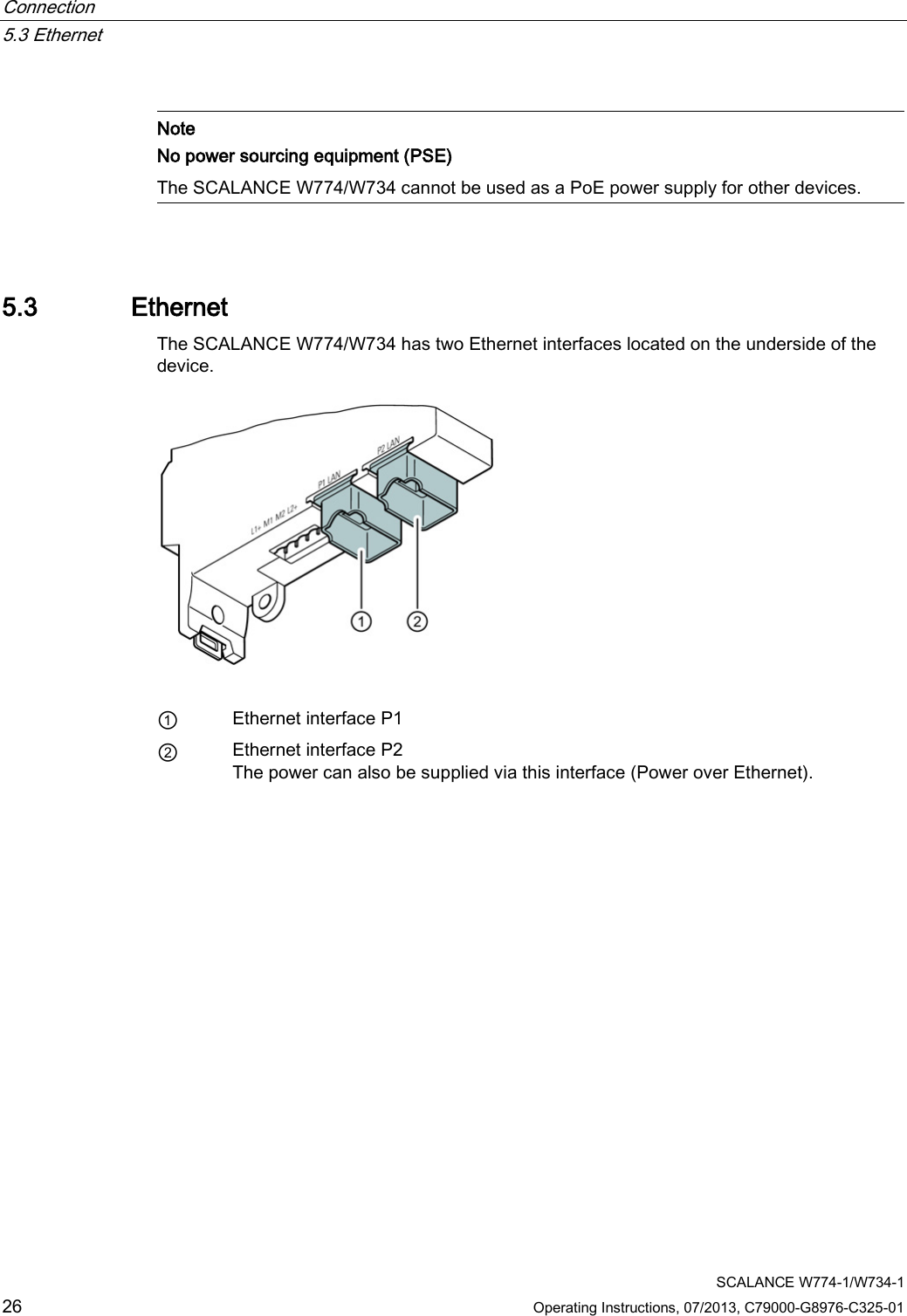
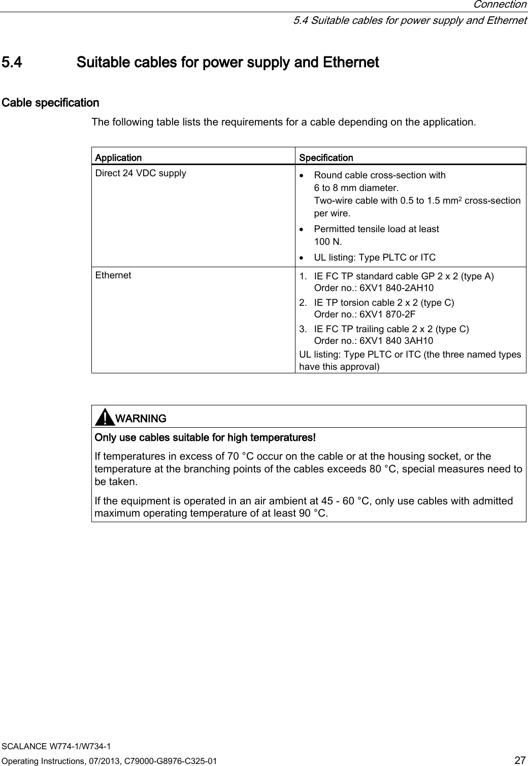
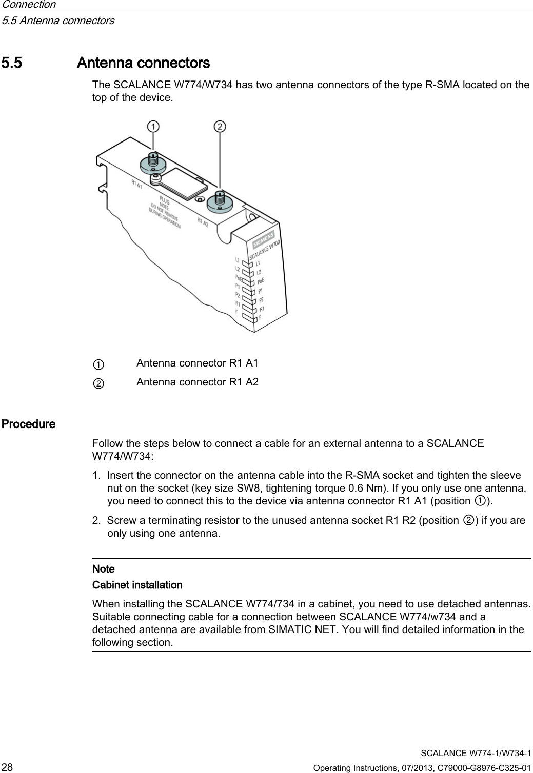
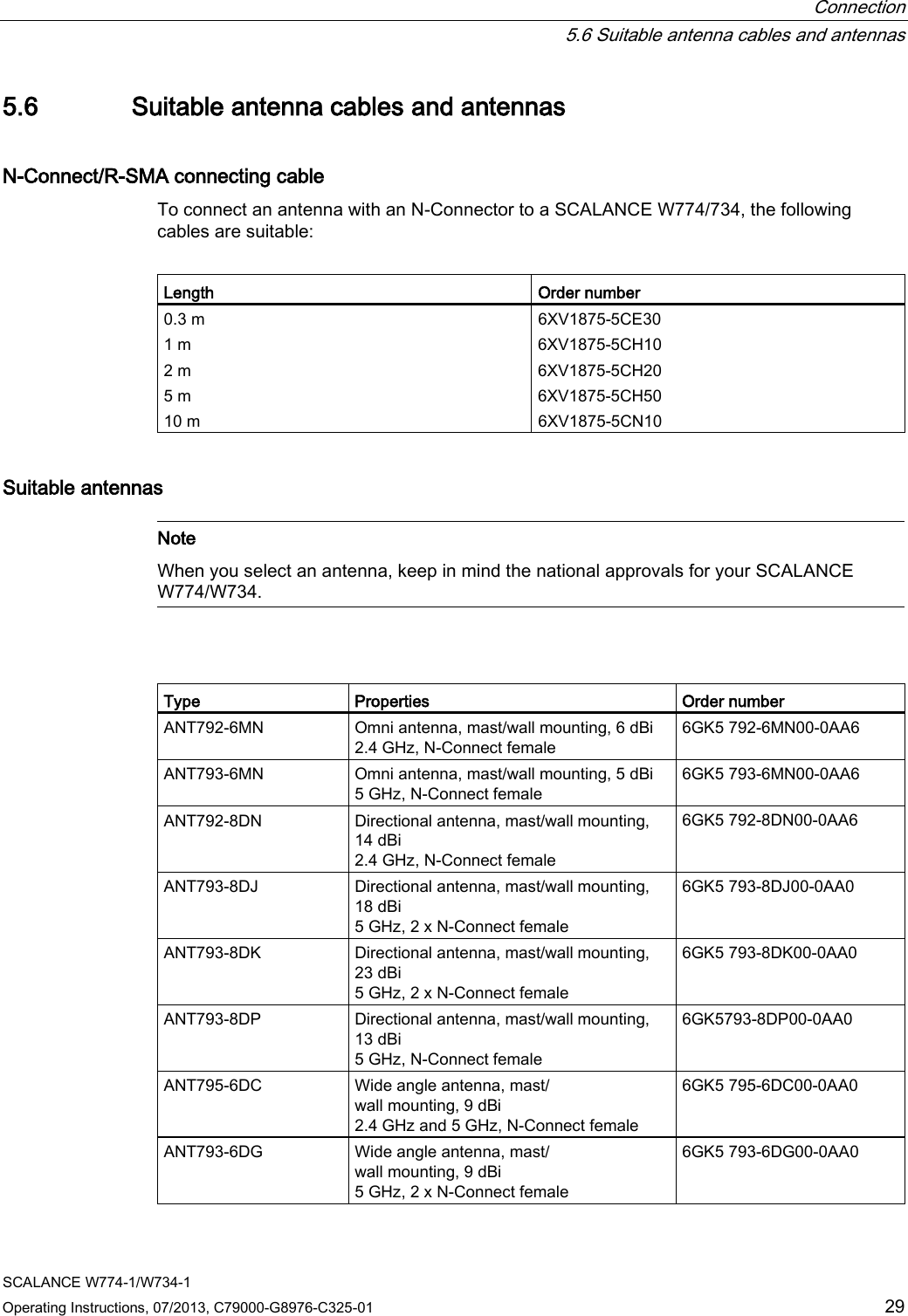
Operating Instructions
4.
Reference Manual
User Manual
Navigation menu
Upload a User Manual
Namespaces
Wiki Guide
HTML
PDF
Info
Views
User Manual
Discussion / Help
Navigation