Siemens RAP-V1 Wireless LAN Access Point User Manual SCALANCE W788 xPRO RR SCALANCE W74x 1PRO RR
Siemens AG Wireless LAN Access Point SCALANCE W788 xPRO RR SCALANCE W74x 1PRO RR
UserManual.wiki
>
Siemens
>
RAP-V1 User Manual
>
User Manual
Contents
1.
User Manual
2.
User Manual Statement
3.
User manual statement FCC Indoor use
4.
Users Manual
5.
Users Manual Statement
User Manual
Navigation menu
Upload a User Manual
Namespaces
Wiki Guide
HTML
PDF
Info
Views
User Manual
Discussion / Help
Navigation
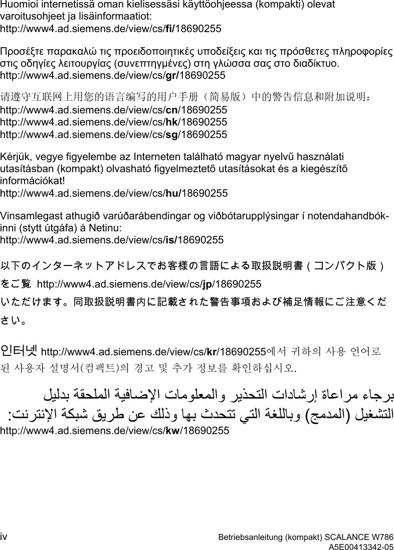

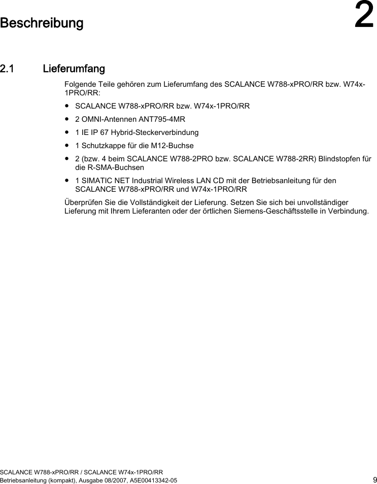
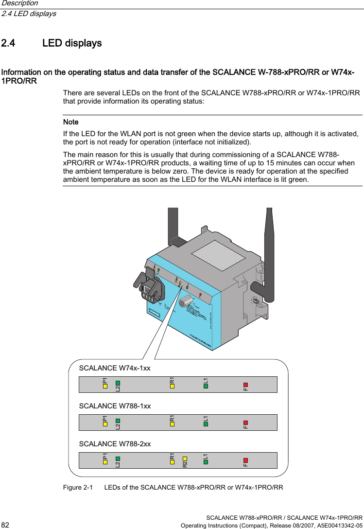
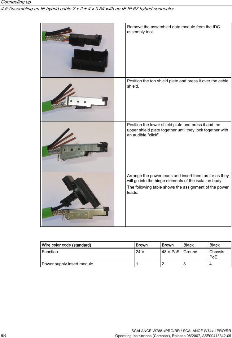
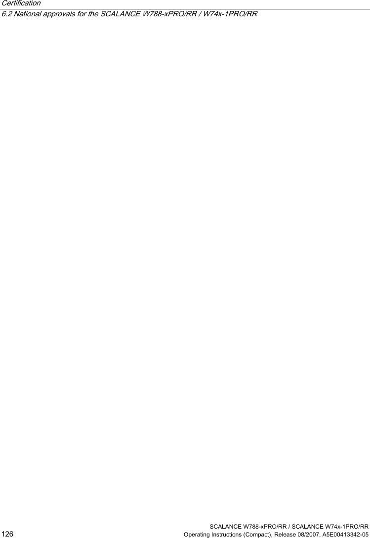
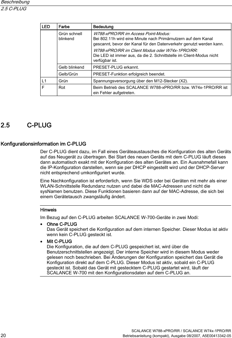
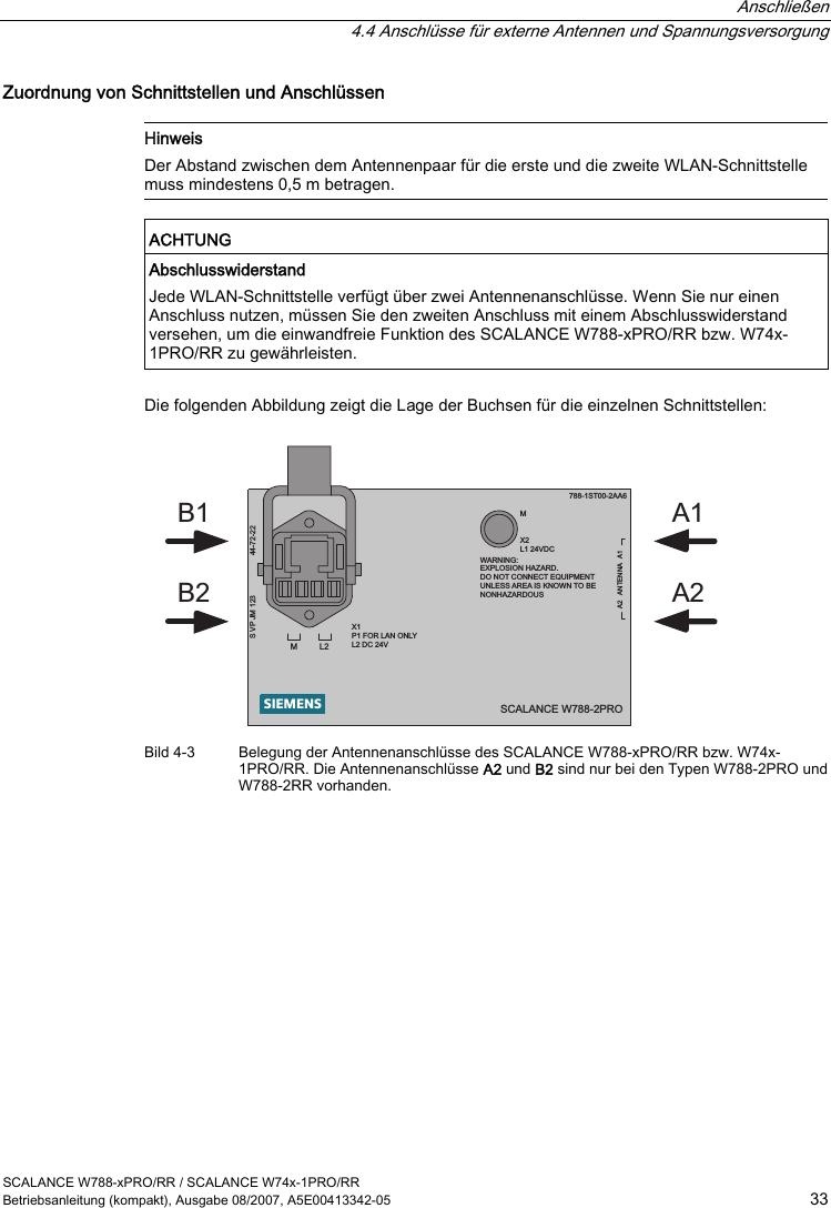
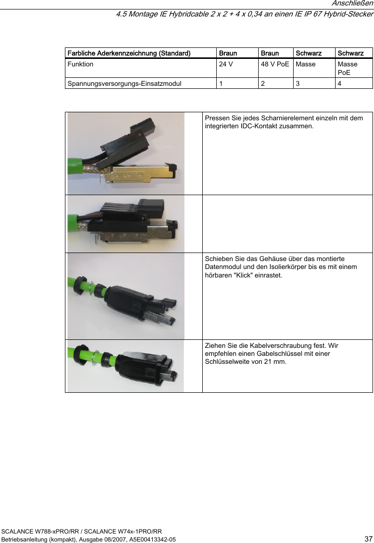
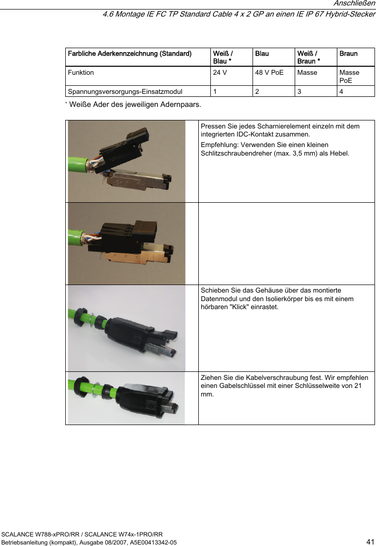
![Beschreibung 2.3 Abweichende Eigenschaften für Geräte mit anderer Hardware SCALANCE W788-xPRO/RR / SCALANCE W74x-1PRO/RR 14 Betriebsanleitung (kompakt), Ausgabe 08/2007, A5E00413342-05 Befehl Beschreibung Kommentar Angabe des Antennentyps. 0 Benutzerdefiniert 1 ANT795-4MR (Standardantenne) - gain: 3 dBi (2,4 GHz) 5 dBi (5 GHz) 2 ANT795-6MR (inkl.. 5m Kabel) - gain: 3 dBi (2,4 GHz) 4 dBi (5 GHz) 3 ANT792-8DR mit 5m Kabel - gain: 10 dBi (2,4 GHz) 4 ANT792-8DR mit 10m Kabel - gain: 6 dBi (2,4 GHz) 5 ANT792-8DR mit 15m Kabel - gain: 3 dBi (2,4 GHz) 6 ANT793-8DRmit 5m Kabel - gain: 14 dBi (5 GHz) 7 ANT792-4DN (RCoax Antenne) - gain: 4 dBi (2,4 GHz) 8 ANT793-4MN (RCoax Antenne) - gain: 6 dBi (5 GHz) anttype [0 ... n] 9 RCoax-Leitung - gain: 0 dBi (2,4 GHz) 0dBi (5 GHz) Zum Anzeigen der Liste geben Sie "anttype ?" ein. Kompatibilität Konfigurationsdaten von einem der oben aufgeführten Geräte können Sie auch für einen SCALANCE W788-xPRO/RR bzw. W74x-1PRO/RR mit einer anderen Bestell-Nummern als in der obigen Tabelle verwenden. Admin-Passwort für die USA-Variante Auch in der USA-Variante ist das Default-Passwort "admin", wenn Sie für den Benutzername "admin" ausgewählt haben. Belegung der Energieadern bei einem Hybridkabel 2 x 2 + 4 x 0,34 Farbliche Aderkennzeichnung (Standard) Braun Braun Schwarz Schwarz Funktion 24 V 24 V Masse Masse Spannungsversorgungs-Einsatzmodul 1 2 3 4](https://usermanual.wiki/Siemens/RAP-V1.User-Manual/User-Guide-911523-Page-20.png)
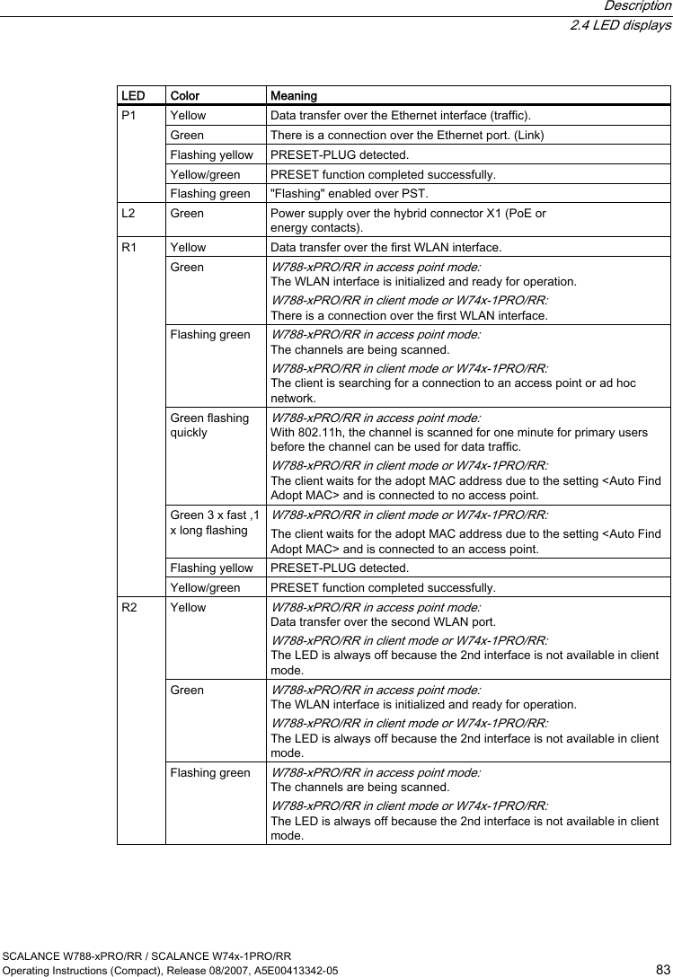
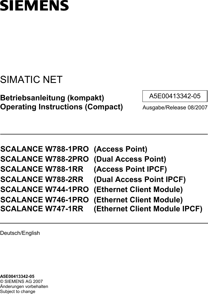
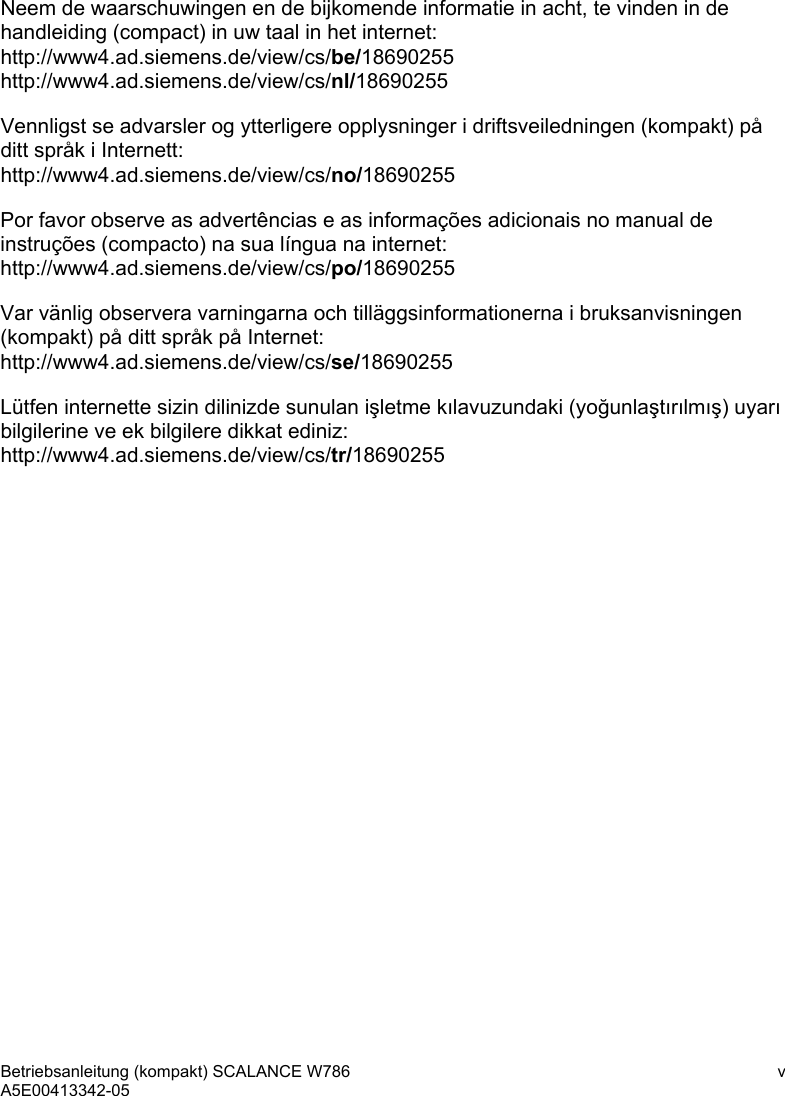
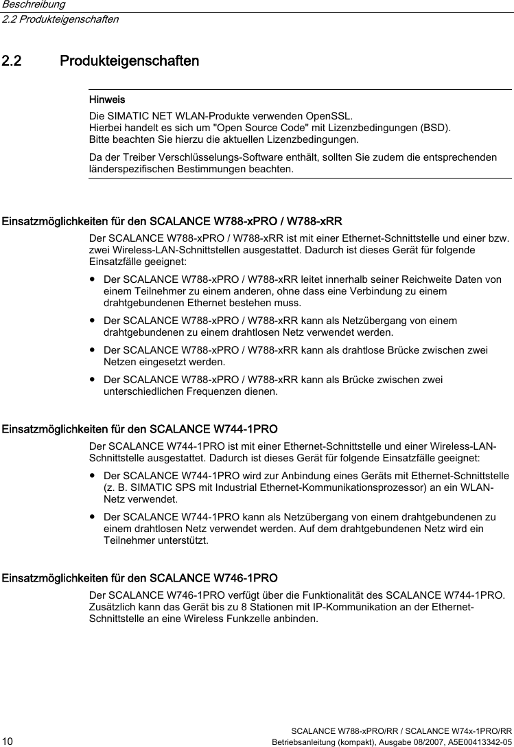
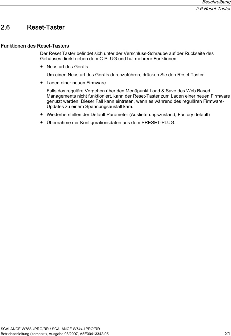
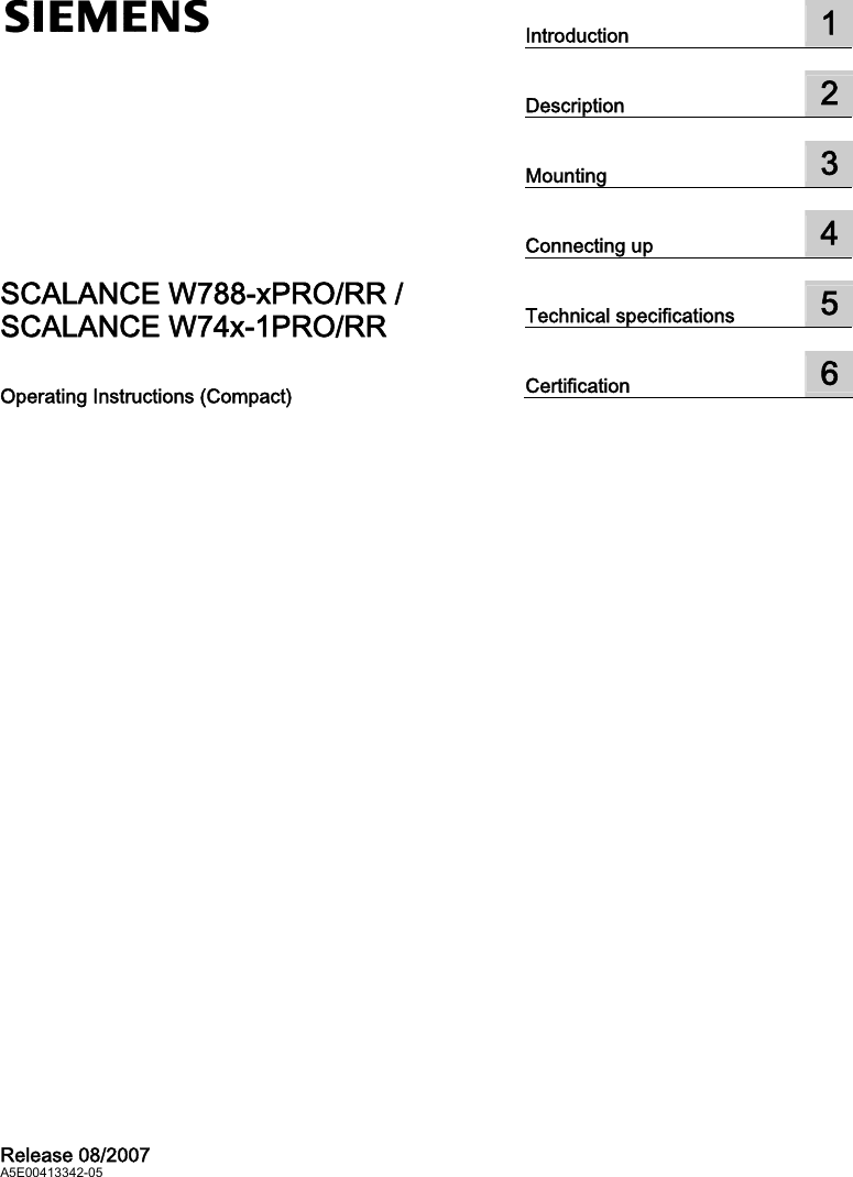
![Beschreibung 2.3 Abweichende Eigenschaften für Geräte mit anderer Hardware SCALANCE W788-xPRO/RR / SCALANCE W74x-1PRO/RR 16 Betriebsanleitung (kompakt), Ausgabe 08/2007, A5E00413342-05 Sendeleistungen Tabelle 2-1 Sendeleistung im IEEE 802.11b-Modus (2,4 GHz) Datenrate [Mb/s] P0 [dBm] 1 18 2 18 5,5 18 11 18 Tabelle 2-2 Sendeleistung im IEEE 802.11g-Modus (2,4 GHz) Datenrate [Mb/s] P0 [dBm] 6 17 9 17 12 17 18 17 24 17 36 13 48 11 54 10 Tabelle 2-3 Sendeleistung im IEEE 802.11a/h-Modus (5 GHz) Datenrate [Mb/s] P0 [dBm] 6 17 9 17 12 17 18 17 24 17 36 13 48 11 54 10](https://usermanual.wiki/Siemens/RAP-V1.User-Manual/User-Guide-911523-Page-22.png)
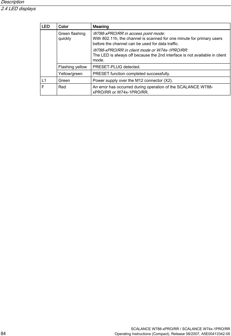
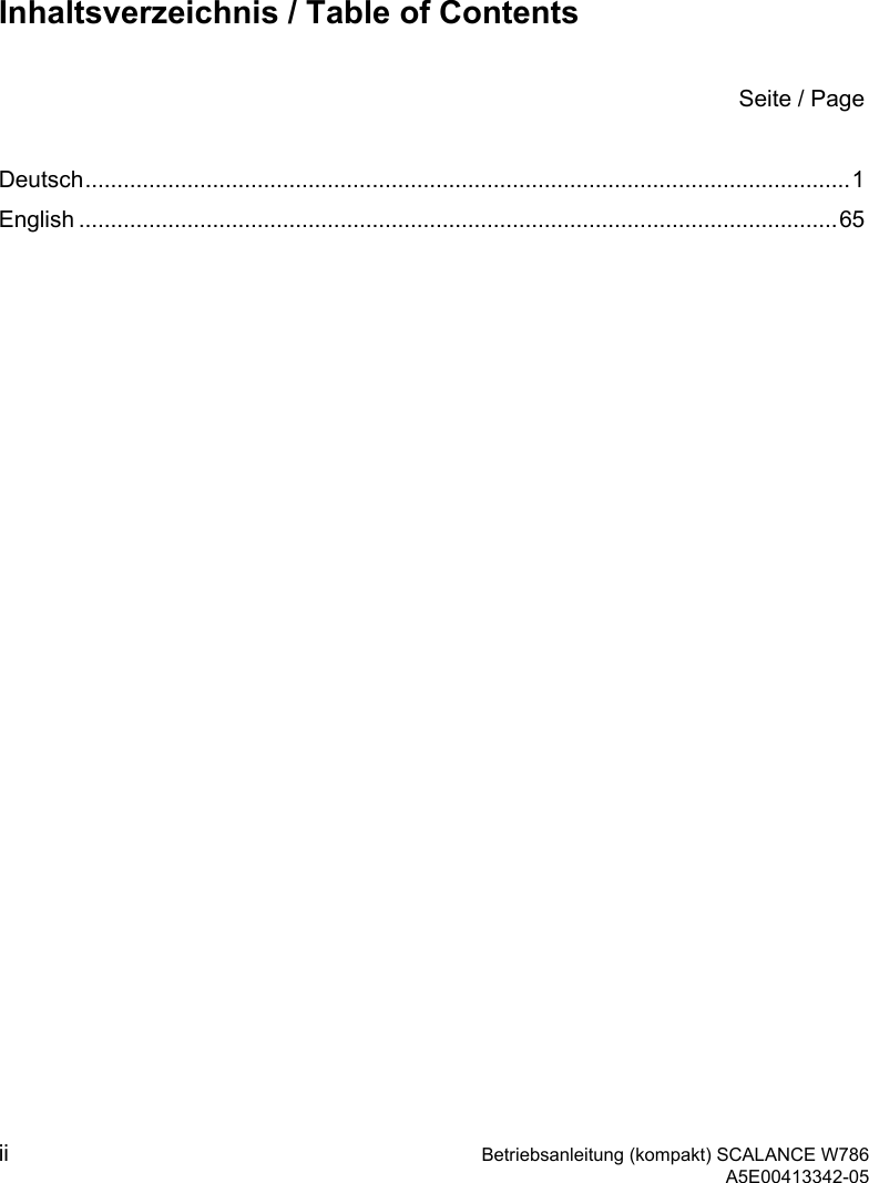
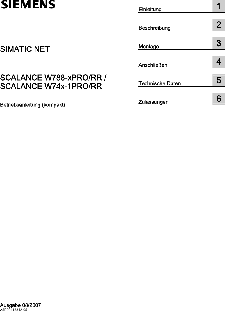
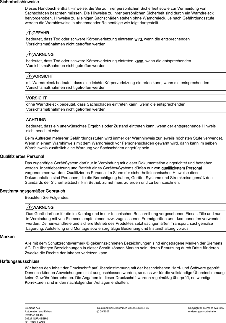
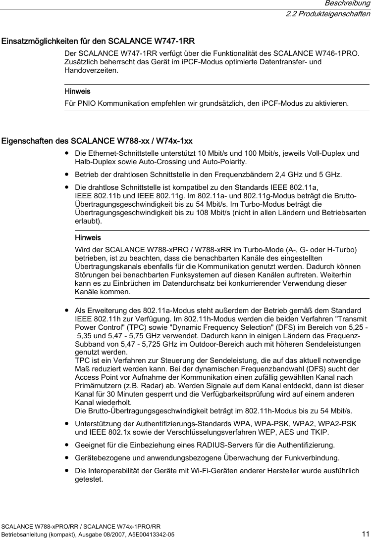
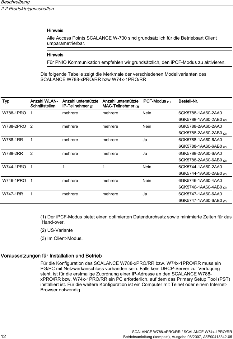
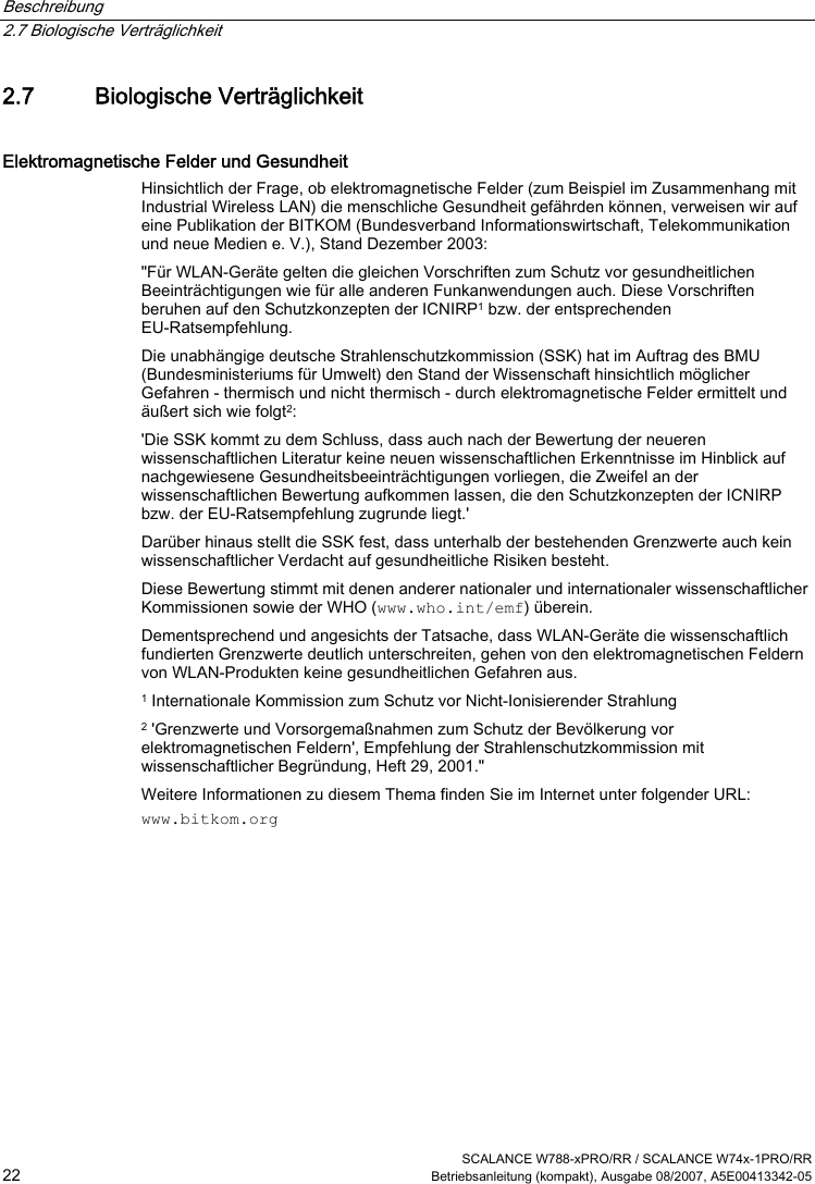
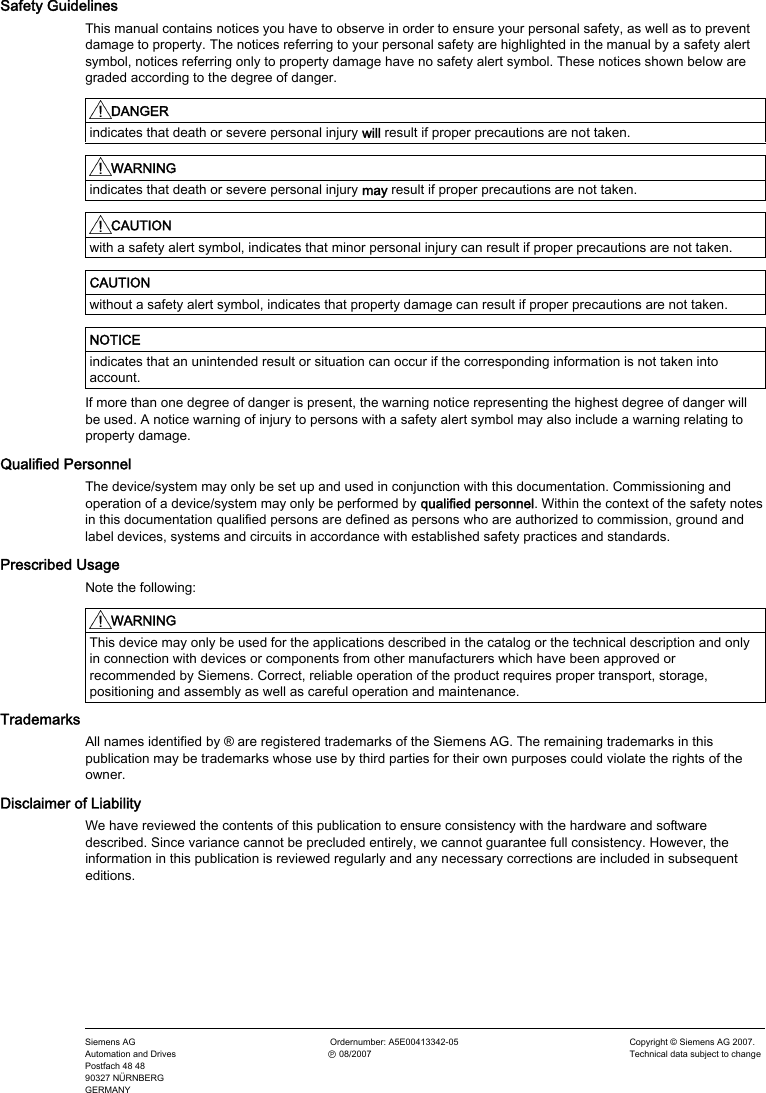
![Beschreibung 2.3 Abweichende Eigenschaften für Geräte mit anderer Hardware SCALANCE W788-xPRO/RR / SCALANCE W74x-1PRO/RR Betriebsanleitung (kompakt), Ausgabe 08/2007, A5E00413342-05 17 Empfängerempfindlichkeit Tabelle 2-4 Empfängerempfindlichkeit im IEEE 802.11b-Modus (2,4 GHz) Datenrate [Mb/s] Pe [dBm] 1 -90 2 -90 5,5 -90 11 -84 Tabelle 2-5 Empfängerempfindlichkeit im IEEE 802.11g-Modus (2,4 GHz) Datenrate [Mb/s] Pe [dBm] 6 -87 9 -86 12 -85 18 -83 24 -80 36 -76 48 -71 54 -66 Tabelle 2-6 Empfängerempfindlichkeit im IEEE 802.11a/h-Modus (5 GHz) Datenrate [Mb/s] Pe [dBm] 6 -87 9 -86 12 -85 18 -83 24 -80 36 -76 48 -71 54 -66 72 [*] -73 96 [*] -68 108 [*] -63 [*] Turbo Mode](https://usermanual.wiki/Siemens/RAP-V1.User-Manual/User-Guide-911523-Page-23.png)
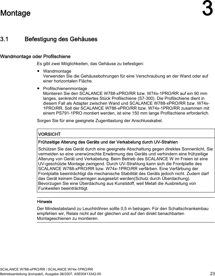


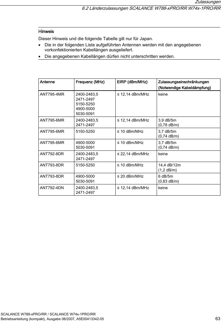

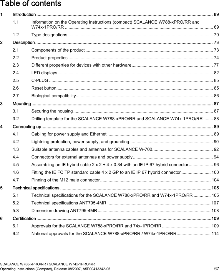

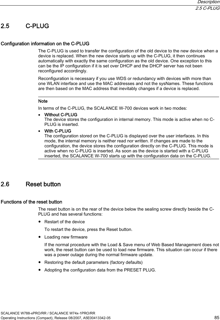
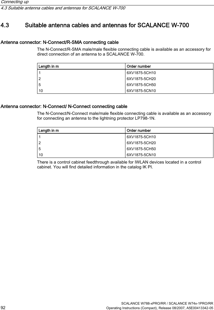
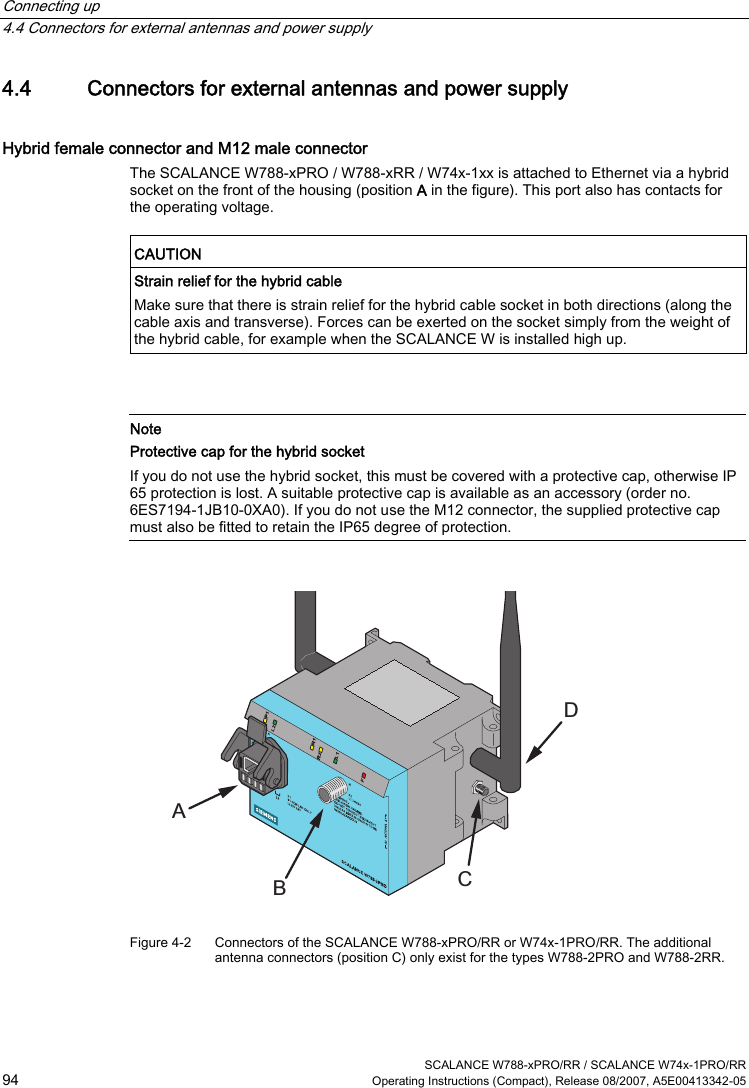
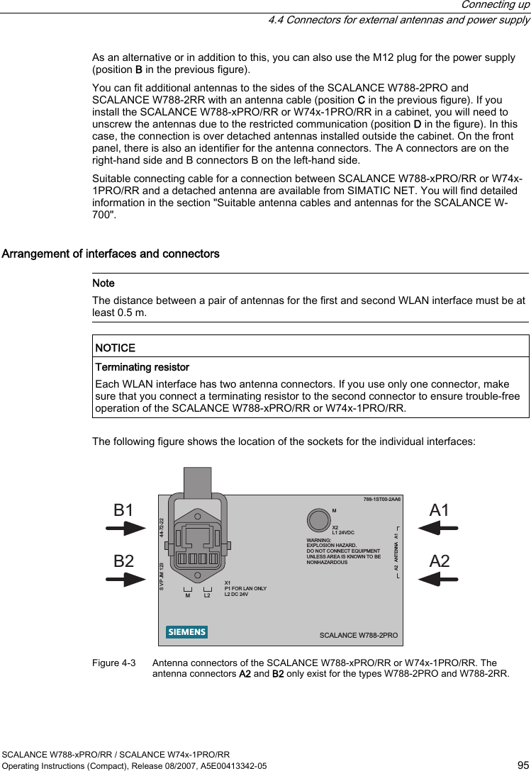
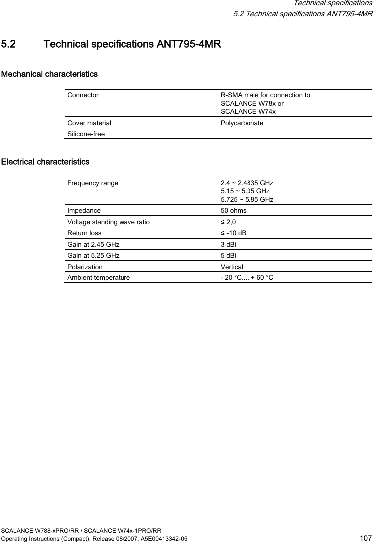
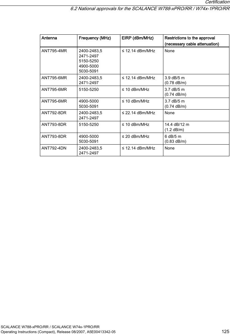
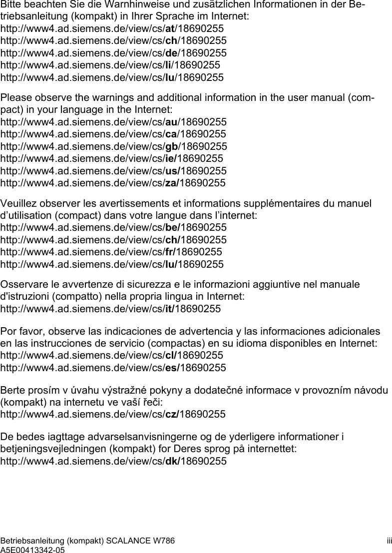
![Description 2.3 Different properties for devices with other hardware SCALANCE W788-xPRO/RR / SCALANCE W74x-1PRO/RR 78 Operating Instructions (Compact), Release 08/2007, A5E00413342-05 Antennas The following antennas are approved for use with the SCALANCE devices listed above. You can select an antenna in Web Based Management or in the Command Line Interface. CLI menu: CLI\INTERFACES\WLAN1\ADVANCED> (or \WLAN2\ADVANCED) Command Description Comment Specify an antenna type. 0 User-defined 1 ANT795-4MR (default antenna) - gain: 3 dBi (2.4 GHz) 5 dBi (5 GHz) 2 ANT795-6MR (incl. 5 m cable) - gain: 3 dBi (2.4 GHz) 4 dBi (5 GHz) 3 ANT792-8DR with 5 m cable - gain: 10 dBi (2.4 GHz) 4 ANT792-8DR with 10 m cable - gain: 6 dBi (2.4 GHz) 5 ANT792-8DR with 15 m cable - gain: 3 dBi (2.4 GHz) 6 ANT793-8DR with 5 m cable - gain: 14 dBi (5 GHz) 7 ANT792-4DN (RCoax antenna) - gain: 4 dBi (2.4 GHz) 8 ANT793-4MN (RCoax antenna) - gain: 6 dBi (5 GHz) anttype [0...n] 9 RCoax cable - gain: 0 dBi (2.4 GHz) 0 dBi (5 GHz) To display the list, enter "anttype ?". Compatibility You can also use configuration data of one of the devices listed above for a SCALANCE W788-xPRO/RR or W74x-1PRO/RR with a different order number from that shown in the table above. Admin password for the USA variant The default password is also "admin" for the USA variant if you have selected "admin" as the user name.](https://usermanual.wiki/Siemens/RAP-V1.User-Manual/User-Guide-911523-Page-84.png)
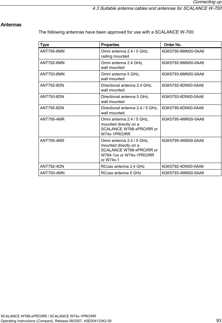
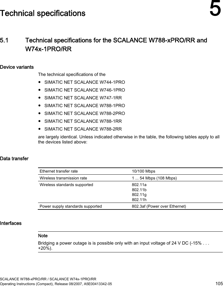
![Description 2.3 Different properties for devices with other hardware SCALANCE W788-xPRO/RR / SCALANCE W74x-1PRO/RR 80 Operating Instructions (Compact), Release 08/2007, A5E00413342-05 Transmit power Table 2-1 Transmit power in IEEE 802.11b mode (2.4 GHz) Data rate [Mbps] P0 [dBm] 1 18 2 18 5,5 18 11 18 Table 2-2 Transmit power in IEEE 802.11g mode (2.4 GHz) Data rate [Mbps] P0 [dBm] 6 17 9 17 12 17 18 17 24 17 36 13 48 11 54 10 Table 2-3 Transmit power in IEEE 802.11a/h mode (5 GHz) Data rate [Mbps] P0 [dBm] 6 17 9 17 12 17 18 17 24 17 36 13 48 11 54 10](https://usermanual.wiki/Siemens/RAP-V1.User-Manual/User-Guide-911523-Page-86.png)
![Description 2.3 Different properties for devices with other hardware SCALANCE W788-xPRO/RR / SCALANCE W74x-1PRO/RR Operating Instructions (Compact), Release 08/2007, A5E00413342-05 81 Receiver sensitivity Table 2-4 Receiver sensitivity in IEEE 802.11b mode (2.4 GHz) Data rate [Mbps] Pe [dBm] 1 -90 2 -90 5,5 -90 11 -84 Table 2-5 Receiver sensitivity in IEEE 802.11g mode (2.4 GHz) Data rate [Mbps] Pe [dBm] 6 -87 9 -86 12 -85 18 -83 24 -80 36 -76 48 -71 54 -66 Table 2-6 Receiver sensitivity in IEEE 802.11a/h mode (5 GHz) Data rate [Mbps] Pe [dBm] 6 -87 9 -86 12 -85 18 -83 24 -80 36 -76 48 -71 54 -66 72 [*] -73 96 [*] -68 108 [*] -63 [*] Turbo mode](https://usermanual.wiki/Siemens/RAP-V1.User-Manual/User-Guide-911523-Page-87.png)