Siemens RAP-V1 Wireless LAN Access Point User Manual SCALANCE W788 xPRO RR SCALANCE W74x 1PRO RR
Siemens AG Wireless LAN Access Point SCALANCE W788 xPRO RR SCALANCE W74x 1PRO RR
Siemens >
Contents
User Manual
SIMATIC NET
Betriebsanleitung (kompakt)
Operating Instructions (Compact) Ausgabe/Release 08/2007
SCALANCE W788-1PRO (Access Point)
SCALANCE W788-2PRO (Dual Access Point)
SCALANCE W788-1RR (Access Point IPCF)
SCALANCE W788-2RR (Dual Access Point IPCF)
SCALANCE W744-1PRO (Ethernet Client Module)
SCALANCE W746-1PRO (Ethernet Client Module)
SCALANCE W747-1RR (Ethernet Client Module IPCF)
Deutsch/English
A5E00413342-05
A5E00413342-05
© SIEMENS AG 2007
Ä
nderungen vorbehalten
Subject to change
ii Betriebsanleitung (kompakt) SCALANCE W786
A5E00413342-05
Inhaltsverzeichnis / Table of Contents
Seite / Page
Deutsch........................................................................................................................1
English .......................................................................................................................65
Betriebsanleitung (kompakt) SCALANCE W786 iii
A5E00413342-05
Bitte beachten Sie die Warnhinweise und zusätzlichen Informationen in der Be-
triebsanleitung (kompakt) in Ihrer Sprache im Internet:
http://www4.ad.siemens.de/view/cs/at/18690255
http://www4.ad.siemens.de/view/cs/ch/18690255
http://www4.ad.siemens.de/view/cs/de/18690255
http://www4.ad.siemens.de/view/cs/li/18690255
http://www4.ad.siemens.de/view/cs/lu/18690255
Please observe the warnings and additional information in the user manual (com-
pact) in your language in the Internet:
http://www4.ad.siemens.de/view/cs/au/18690255
http://www4.ad.siemens.de/view/cs/ca/18690255
http://www4.ad.siemens.de/view/cs/gb/18690255
http://www4.ad.siemens.de/view/cs/ie/18690255
http://www4.ad.siemens.de/view/cs/us/18690255
http://www4.ad.siemens.de/view/cs/za/18690255
Veuillez observer les avertissements et informations supplémentaires du manuel
d’utilisation (compact) dans votre langue dans l’internet:
http://www4.ad.siemens.de/view/cs/be/18690255
http://www4.ad.siemens.de/view/cs/ch/18690255
http://www4.ad.siemens.de/view/cs/fr/18690255
http://www4.ad.siemens.de/view/cs/lu/18690255
Osservare le avvertenze di sicurezza e le informazioni aggiuntive nel manuale
d'istruzioni (compatto) nella propria lingua in Internet:
http://www4.ad.siemens.de/view/cs/it/18690255
Por favor, observe las indicaciones de advertencia y las informaciones adicionales
en las instrucciones de servicio (compactas) en su idioma disponibles en Internet:
http://www4.ad.siemens.de/view/cs/cl/18690255
http://www4.ad.siemens.de/view/cs/es/18690255
Berte prosím v úvahu výstražné pokyny a dodatečné informace v provozním návodu
(kompakt) na internetu ve vaší řeči:
http://www4.ad.siemens.de/view/cs/cz/18690255
De bedes iagttage advarselsanvisningerne og de yderligere informationer i
betjeningsvejledningen (kompakt) for Deres sprog på internettet:
http://www4.ad.siemens.de/view/cs/dk/18690255
iv Betriebsanleitung (kompakt) SCALANCE W786
A5E00413342-05
Huomioi internetissä oman kielisessäsi käyttöohjeessa (kompakti) olevat
varoitusohjeet ja lisäinformaatiot:
http://www4.ad.siemens.de/view/cs/fi/18690255
Προσέξτε παρακαλώ τις προειδοποιητικές υποδείξεις και τις πρόσθετες πληροφορίες
στις οδηγίες λειτουργίας (συνεπτηγμένες) στη γλώσσα σας στο διαδίκτυο.
http://www4.ad.siemens.de/view/cs/gr/18690255
请遵守互联网上用您的语言编写的用户手册(简易版)中的警告信息和附加说明:
http://www4.ad.siemens.de/view/cs/cn/18690255
http://www4.ad.siemens.de/view/cs/hk/18690255
http://www4.ad.siemens.de/view/cs/sg/18690255
Kérjük, vegye figyelembe az Interneten található magyar nyelvű használati
utasításban (kompakt) olvasható figyelmeztető utasításokat és a kiegészítő
információkat!
http://www4.ad.siemens.de/view/cs/hu/18690255
Vinsamlegast athugið varúðarábendingar og viðbótarupplýsingar í notendahandbók-
inni (stytt útgáfa) á Netinu:
http://www4.ad.siemens.de/view/cs/is/18690255
以下のインターネットアドレスでお客様の言語による取扱説明書(コンパクト版)
をご覧 http://www4.ad.siemens.de/view/cs/jp/18690255
いただけます。同取扱説明書内に記載された警告事項および補足情報にご注意くだ
さい。
인터넷 http://www4.ad.siemens.de/view/cs/kr/18690255에서 귀하의 사용 언어로
된 사용자 설명서(컴팩트)의 경고 및 추가 정보를 확인하십시오.
ﻞﻴﻟﺪﺑ ﺔﻘﺤﻠﻤﻟا ﺔﻴﻓﺎﺿﻹا تﺎﻣﻮﻠﻌﻤﻟاو ﺮﻳﺬﺤﺘﻟا تادﺎﺷرإ ةﺎﻋاﺮﻣ ءﺎﺟﺮﺑ
ﻞﻴﻐﺸﺘﻟا)ﺞﻣﺪﻤﻟا (ﻟﺎﺑوﺖﻧﺮﺘﻧﻹا ﺔﻜﺒﺷ ﻖﻳﺮﻃ ﻦﻋ ﻚﻟذو ﺎﻬﺑ ثﺪﺤﺘﺗ ﻲﺘﻟا ﺔﻐﻠ:
http://www4.ad.siemens.de/view/cs/kw/18690255
Betriebsanleitung (kompakt) SCALANCE W786 v
A5E00413342-05
Neem de waarschuwingen en de bijkomende informatie in acht, te vinden in de
handleiding (compact) in uw taal in het internet:
http://www4.ad.siemens.de/view/cs/be/18690255
http://www4.ad.siemens.de/view/cs/nl/18690255
Vennligst se advarsler og ytterligere opplysninger i driftsveiledningen (kompakt) på
ditt språk i Internett:
http://www4.ad.siemens.de/view/cs/no/18690255
Por favor observe as advertências e as informações adicionais no manual de
instruções (compacto) na sua língua na internet:
http://www4.ad.siemens.de/view/cs/po/18690255
Var vänlig observera varningarna och tilläggsinformationerna i bruksanvisningen
(kompakt) på ditt språk på Internet:
http://www4.ad.siemens.de/view/cs/se/18690255
Lütfen internette sizin dilinizde sunulan işletme kılavuzundaki (yoğunlaştırılmış) uyarı
bilgilerine ve ek bilgilere dikkat ediniz:
http://www4.ad.siemens.de/view/cs/tr/18690255
vi Betriebsanleitung (kompakt) SCALANCE W786
A5E00413342-05

Einleitung
1
Beschreibung
2
Montage
3
Anschließen
4
Technische Daten
5
Zulassungen
6
SIMATIC NET
SCALANCE W788-xPRO/RR /
SCALANCE W74x-1PRO/RR
Betriebsanleitung (kompakt)
A
usgabe 08/2007
A5E00413342-05
Sicherheitshinweise
Dieses Handbuch enthält Hinweise, die Sie zu Ihrer persönlichen Sicherheit sowie zur Vermeidung von
Sachschäden beachten müssen. Die Hinweise zu Ihrer persönlichen Sicherheit sind durch ein Warndreieck
hervorgehoben, Hinweise zu alleinigen Sachschäden stehen ohne Warndreieck. Je nach Gefährdungsstufe
werden die Warnhinweise in abnehmender Reihenfolge wie folgt dargestellt.
GEFAHR
bedeutet, dass Tod oder schwere Körperverletzung eintreten wird, wenn die entsprechenden
Vorsichtsmaßnahmen nicht getroffen werden.
WARNUNG
bedeutet, dass Tod oder schwere Körperverletzung eintreten kann, wenn die entsprechenden
Vorsichtsmaßnahmen nicht getroffen werden.
VORSICHT
mit Warndreieck bedeutet, dass eine leichte Körperverletzung eintreten kann, wenn die entsprechenden
Vorsichtsmaßnahmen nicht getroffen werden.
VORSICHT
ohne Warndreieck bedeutet, dass Sachschaden eintreten kann, wenn die entsprechenden
Vorsichtsmaßnahmen nicht getroffen werden.
ACHTUNG
bedeutet, dass ein unerwünschtes Ergebnis oder Zustand eintreten kann, wenn der entsprechende Hinweis
nicht beachtet wird.
Beim Auftreten mehrerer Gefährdungsstufen wird immer der Warnhinweis zur jeweils höchsten Stufe verwendet.
Wenn in einem Warnhinweis mit dem Warndreieck vor Personenschäden gewarnt wird, dann kann im selben
Warnhinweis zusätzlich eine Warnung vor Sachschäden angefügt sein.
Qualifiziertes Personal
Das zugehörige Gerät/System darf nur in Verbindung mit dieser Dokumentation eingerichtet und betrieben
werden. Inbetriebsetzung und Betrieb eines Gerätes/Systems dürfen nur von qualifiziertem Personal
vorgenommen werden. Qualifiziertes Personal im Sinne der sicherheitstechnischen Hinweise dieser
Dokumentation sind Personen, die die Berechtigung haben, Geräte, Systeme und Stromkreise gemäß den
Standards der Sicherheitstechnik in Betrieb zu nehmen, zu erden und zu kennzeichnen.
Bestimmungsgemäßer Gebrauch
Beachten Sie Folgendes:
WARNUNG
Das Gerät darf nur für die im Katalog und in der technischen Beschreibung vorgesehenen Einsatzfälle und nur
in Verbindung mit von Siemens empfohlenen bzw. zugelassenen Fremdgeräten und -komponenten verwendet
werden. Der einwandfreie und sichere Betrieb des Produktes setzt sachgemäßen Transport, sachgemäße
Lagerung, Aufstellung und Montage sowie sorgfältige Bedienung und Instandhaltung voraus.
Marken
Alle mit dem Schutzrechtsvermerk ® gekennzeichneten Bezeichnungen sind eingetragene Marken der Siemens
AG. Die übrigen Bezeichnungen in dieser Schrift können Marken sein, deren Benutzung durch Dritte für deren
Zwecke die Rechte der Inhaber verletzen kann.
Haftungsausschluss
Wir haben den Inhalt der Druckschrift auf Übereinstimmung mit der beschriebenen Hard- und Software geprüft.
Dennoch können Abweichungen nicht ausgeschlossen werden, so dass wir für die vollständige Übereinstimmung
keine Gewähr übernehmen. Die Angaben in dieser Druckschrift werden regelmäßig überprüft, notwendige
Korrekturen sind in den nachfolgenden Auflagen enthalten.
Siemens AG
Automation and Drives
Postfach 48 48
90327 NÜRNBERG
DEUTSCHLAND
Dokumentbestellnummer: A5E00413342-05
Ⓟ 09/2007
Copyright © Siemens AG 2007.
Änderungen vorbehalten
SCALANCE W788-xPRO/RR / SCALANCE W74x-1PRO/RR
Betriebsanleitung (kompakt), Ausgabe 08/2007, A5E00413342-05 3
Inhaltsverzeichnis
1 Einleitung.................................................................................................................................................. 5
1.1 Informationen zur Betriebsanleitung (kompakt) SCALANCE W788-xPRO/RR und W74x-
1PRO/RR....................................................................................................................................... 5
1.2 Typenbezeichungen ...................................................................................................................... 6
2 Beschreibung............................................................................................................................................ 9
2.1 Lieferumfang.................................................................................................................................. 9
2.2 Produkteigenschaften.................................................................................................................. 10
2.3 Abweichende Eigenschaften für Geräte mit anderer Hardware.................................................. 13
2.4 Leuchtdiodenanzeigen................................................................................................................. 18
2.5 C-PLUG ....................................................................................................................................... 20
2.6 Reset-Taster ................................................................................................................................ 21
2.7 Biologische Verträglichkeit .......................................................................................................... 22
3 Montage.................................................................................................................................................. 23
3.1 Befestigung des Gehäuses ......................................................................................................... 23
3.2 Bohrbild SCALANCE W788-xPRO/RR und SCALANCE W74x-1PRO/RR ................................ 24
4 Anschließen ............................................................................................................................................ 25
4.1 Verkabelung für Spannungsversorgung und Ethernet................................................................ 25
4.2 Blitzschutz, Versorgungsspannung und Erdung ......................................................................... 26
4.3 Geeignete Antennenleitungen und Antennen für den SCALANCE W-700................................. 29
4.4 Anschlüsse für externe Antennen und Spannungsversorgung................................................... 31
4.5 Montage IE Hybridcable 2 x 2 + 4 x 0,34 an einen IE IP 67 Hybrid-Stecker .............................. 34
4.6 Montage IE FC TP Standard Cable 4 x 2 GP an einen IE IP 67 Hybrid-Stecker........................ 38
4.7 Pinbelegung des M12-Anschluss-Steckers................................................................................. 42
5 Technische Daten................................................................................................................................... 43
5.1 Technische Daten SCALANCE W788-xPRO/RR und W74x-1PRO/RR..................................... 43
5.2 Technische Daten ANT795-4MR................................................................................................. 45
5.3 Maßzeichnung ANT795-4MR ...................................................................................................... 46
6 Zulassungen ........................................................................................................................................... 47
6.1 Zulassungen SCALANCE W788-xPRO/RR und 74x-1PRO/RR................................................. 47
6.2 Länderzulassungen SCALANCE W788-xPRO/RR W74x-1PRO/RR ......................................... 52

SCALANCE W788-xPRO/RR / SCALANCE W74x-1PRO/RR
Betriebsanleitung (kompakt), Ausgabe 08/2007, A5E00413342-05 5
Einleitung 1
1.1 Informationen zur Betriebsanleitung (kompakt)
SCALANCE W788-xPRO/RR und W74x-1PRO/RR
Gültigkeitsbereich der Betriebsanleitung (kompakt)
Die vorliegende Betriebsanleitung (kompakt) behandelt die folgenden Produkte:
● SCALANCE W788-1PRO
● SCALANCE W788-2PRO
● SCALANCE W788-1RR
● SCALANCE W788-2RR
● SCALANCE W744-1PRO
● SCALANCE W746-1PRO
● SCALANCE W747-1RR
Die Betriebsanleitung (kompakt) gilt für folgende Software-Version:
● SCALANCE W788-xPRO/RR bzw. W74x-1PRO/RR mit Firmware ab Version 3.3
Zweck der Betriebsanleitung (kompakt)
Die Betriebsanleitung (kompakt) soll Sie in die Lage versetzen, den SCALANCE W788-
xPRO/RR bzw. W74x-1PRO/RR fachgerecht zu montieren und anzuschließen. Die
Konfiguration sowie die Einbindung des Geräts in ein WLAN-Netz sind nicht Gegenstand
dieser Anleitung.
Dokumentation auf der beiliegenden CD
Die Betriebsanleitung zu den oben genannten Produkten finden Sie auf der beiliegenden CD
unter dem Dateinamen
BA_SCALANCE-W788-xPRORR-W74x-1PRORR_0.pdf
ACHTUNG
Beachten Sie unbedingt die Erläuterungen und Hinweise in der Datei LIESMICH.txt

Einleitung
1.2 Typenbezeichungen
SCALANCE W788-xPRO/RR / SCALANCE W74x-1PRO/RR
6 Betriebsanleitung (kompakt), Ausgabe 08/2007, A5E00413342-05
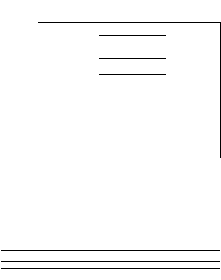
1.2 Typenbezeichungen
Verwendete Abkürzungen
Die Informationen in den Handbüchern der SCALANCE W-700-Produktfamilie gelten häufig
nicht nur für eine Produktvariante. In diesen Fällen werden abkürzende Bezeichnungen
verwendet, um nicht alle Typenbezeichnungen aufzählen zu müssen. Die folgende Tabelle
zeigt die Zuordnung von Abkürzungen und Produktvarianten.
Produktgruppe Die Bezeichnung . . . steht
für . . .
Produktname
Ethernet Client Module (IP30,
Schaltschrankeinbau)
W74x-1 W744-1
W746-1
W747-1
Ethernet Client Module (IP65,
Aufstellung außerhalb eines
Schaltschranks)
W74x-1PRO/RR W744-1PRO
W746-1PRO
W747-1RR
Alle Ethernet Client Module
SCALANCE W
W74x W744-1
W746-1
W747-1
W744-1PRO
W746-1PRO
W747-1RR
Access Points (IP30,
Schaltschrankeinbau)
W784-1xx W784-1
W784-1RR
Access Points (IP65, Aufstellung
außerhalb eines Schaltschranks, hohe
klimatische Anforderungen)
W786-xPRO W786-1PRO
W786-2PRO
W786-3PRO
Access Points (IP65, Aufstellung
außerhalb eines Schaltschranks)
W788-xPRO/RR W788-1PRO
W788-2PRO
W788-1RR
W788-2RR
Access Points mit dem
Funktionsumfang "RR"
W-78x-xRR W784-1RR
W788-1RR
W788-2RR
Alle Access Points SCALANCE W W78x W788-1PRO
W788-2PRO
W788-1RR
W788-2RR
W786-1PRO
W786-2PRO
W786-3PRO
W784-1
W784-1RR

Einleitung
1.2 Typenbezeichungen
SCALANCE W788-xPRO/RR / SCALANCE W74x-1PRO/RR
Betriebsanleitung (kompakt), Ausgabe 08/2007, A5E00413342-05 7
Produktgruppe Die Bezeichnung . . . steht
für . . .
Produktname
Alle SCALANCE W W-700 W788-1PRO
W788-2PRO
W788-1RR
W788-2RR
W744-1PRO
W746-1PRO
W747-1RR
W786-1PRO
W786-2PRO
W786-3PRO
W784-1
W784-1RR
W744-1
W746-1
W747-1
SCALANCE W788-xPRO/RR / SCALANCE W74x-1PRO/RR
Betriebsanleitung (kompakt), Ausgabe 08/2007, A5E00413342-05 9
Beschreibung 2
2.1 Lieferumfang
Folgende Teile gehören zum Lieferumfang des SCALANCE W788-xPRO/RR bzw. W74x-
1PRO/RR:
● SCALANCE W788-xPRO/RR bzw. W74x-1PRO/RR
● 2 OMNI-Antennen ANT795-4MR
● 1 IE IP 67 Hybrid-Steckerverbindung
● 1 Schutzkappe für die M12-Buchse
● 2 (bzw. 4 beim SCALANCE W788-2PRO bzw. SCALANCE W788-2RR) Blindstopfen für
die R-SMA-Buchsen
● 1 SIMATIC NET Industrial Wireless LAN CD mit der Betriebsanleitung für den
SCALANCE W788-xPRO/RR und W74x-1PRO/RR
Überprüfen Sie die Vollständigkeit der Lieferung. Setzen Sie sich bei unvollständiger
Lieferung mit Ihrem Lieferanten oder der örtlichen Siemens-Geschäftsstelle in Verbindung.

Beschreibung
2.2 Produkteigenschaften
SCALANCE W788-xPRO/RR / SCALANCE W74x-1PRO/RR
10 Betriebsanleitung (kompakt), Ausgabe 08/2007, A5E00413342-05
2.2 Produkteigenschaften
Hinweis
Die SIMATIC NET WLAN-Produkte verwenden OpenSSL.
Hierbei handelt es sich um "Open Source Code" mit Lizenzbedingungen (BSD).
Bitte beachten Sie hierzu die aktuellen Lizenzbedingungen.
Da der Treiber Verschlüsselungs-Software enthält, sollten Sie zudem die entsprechenden
länderspezifischen Bestimmungen beachten.
Einsatzmöglichkeiten für den SCALANCE W788-xPRO / W788-xRR
Der SCALANCE W788-xPRO / W788-xRR ist mit einer Ethernet-Schnittstelle und einer bzw.
zwei Wireless-LAN-Schnittstellen ausgestattet. Dadurch ist dieses Gerät für folgende
Einsatzfälle geeignet:
● Der SCALANCE W788-xPRO / W788-xRR leitet innerhalb seiner Reichweite Daten von
einem Teilnehmer zu einem anderen, ohne dass eine Verbindung zu einem
drahtgebundenen Ethernet bestehen muss.
● Der SCALANCE W788-xPRO / W788-xRR kann als Netzübergang von einem
drahtgebundenen zu einem drahtlosen Netz verwendet werden.
● Der SCALANCE W788-xPRO / W788-xRR kann als drahtlose Brücke zwischen zwei
Netzen eingesetzt werden.
● Der SCALANCE W788-xPRO / W788-xRR kann als Brücke zwischen zwei
unterschiedlichen Frequenzen dienen.
Einsatzmöglichkeiten für den SCALANCE W744-1PRO
Der SCALANCE W744-1PRO ist mit einer Ethernet-Schnittstelle und einer Wireless-LAN-
Schnittstelle ausgestattet. Dadurch ist dieses Gerät für folgende Einsatzfälle geeignet:
● Der SCALANCE W744-1PRO wird zur Anbindung eines Geräts mit Ethernet-Schnittstelle
(z. B. SIMATIC SPS mit Industrial Ethernet-Kommunikationsprozessor) an ein WLAN-
Netz verwendet.
● Der SCALANCE W744-1PRO kann als Netzübergang von einem drahtgebundenen zu
einem drahtlosen Netz verwendet werden. Auf dem drahtgebundenen Netz wird ein
Teilnehmer unterstützt.
Einsatzmöglichkeiten für den SCALANCE W746-1PRO
Der SCALANCE W746-1PRO verfügt über die Funktionalität des SCALANCE W744-1PRO.
Zusätzlich kann das Gerät bis zu 8 Stationen mit IP-Kommunikation an der Ethernet-
Schnittstelle an eine Wireless Funkzelle anbinden.

Beschreibung
2.2 Produkteigenschaften
SCALANCE W788-xPRO/RR / SCALANCE W74x-1PRO/RR
Betriebsanleitung (kompakt), Ausgabe 08/2007, A5E00413342-05 11
Einsatzmöglichkeiten für den SCALANCE W747-1RR
Der SCALANCE W747-1RR verfügt über die Funktionalität des SCALANCE W746-1PRO.
Zusätzlich beherrscht das Gerät im iPCF-Modus optimierte Datentransfer- und
Handoverzeiten.
Hinweis
Für PNIO Kommunikation empfehlen wir grundsätzlich, den iPCF-Modus zu aktivieren.
Eigenschaften des SCALANCE W788-xx / W74x-1xx
● Die Ethernet-Schnittstelle unterstützt 10 Mbit/s und 100 Mbit/s, jeweils Voll-Duplex und
Halb-Duplex sowie Auto-Crossing und Auto-Polarity.
● Betrieb der drahtlosen Schnittstelle in den Frequenzbändern 2,4 GHz und 5 GHz.
● Die drahtlose Schnittstelle ist kompatibel zu den Standards IEEE 802.11a,
IEEE 802.11b und IEEE 802.11g. Im 802.11a- und 802.11g-Modus beträgt die Brutto-
Übertragungsgeschwindigkeit bis zu 54 Mbit/s. Im Turbo-Modus beträgt die
Übertragungsgeschwindigkeit bis zu 108 Mbit/s (nicht in allen Ländern und Betriebsarten
erlaubt).
Hinweis
Wird der SCALANCE W788-xPRO / W788-xRR im Turbo-Mode (A-, G- oder H-Turbo)
betrieben, ist zu beachten, dass die benachbarten Kanäle des eingestellten
Übertragungskanals ebenfalls für die Kommunikation genutzt werden. Dadurch können
Störungen bei benachbarten Funksystemen auf diesen Kanälen auftreten. Weiterhin
kann es zu Einbrüchen im Datendurchsatz bei konkurrierender Verwendung dieser
Kanäle kommen.
● Als Erweiterung des 802.11a-Modus steht außerdem der Betrieb gemäß dem Standard
IEEE 802.11h zur Verfügung. Im 802.11h-Modus werden die beiden Verfahren "Transmit
Power Control" (TPC) sowie "Dynamic Frequency Selection" (DFS) im Bereich von 5,25 -
5,35 und 5,47 - 5,75 GHz verwendet. Dadurch kann in einigen Ländern das Frequenz-
Subband von 5,47 - 5,725 GHz im Outdoor-Bereich auch mit höheren Sendeleistungen
genutzt werden.
TPC ist ein Verfahren zur Steuerung der Sendeleistung, die auf das aktuell notwendige
Maß reduziert werden kann. Bei der dynamischen Frequenzbandwahl (DFS) sucht der
Access Point vor Aufnahme der Kommunikation einen zufällig gewählten Kanal nach
Primärnutzern (z.B. Radar) ab. Werden Signale auf dem Kanal entdeckt, dann ist dieser
Kanal für 30 Minuten gesperrt und die Verfügbarkeitsprüfung wird auf einem anderen
Kanal wiederholt.
Die Brutto-Übertragungsgeschwindigkeit beträgt im 802.11h-Modus bis zu 54 Mbit/s.
● Unterstützung der Authentifizierungs-Standards WPA, WPA-PSK, WPA2, WPA2-PSK
und IEEE 802.1x sowie der Verschlüsselungsverfahren WEP, AES und TKIP.
● Geeignet für die Einbeziehung eines RADIUS-Servers für die Authentifizierung.
● Gerätebezogene und anwendungsbezogene Überwachung der Funkverbindung.
● Die Interoperabilität der Geräte mit Wi-Fi-Geräten anderer Hersteller wurde ausführlich
getestet.

Beschreibung
2.2 Produkteigenschaften
SCALANCE W788-xPRO/RR / SCALANCE W74x-1PRO/RR
12 Betriebsanleitung (kompakt), Ausgabe 08/2007, A5E00413342-05
Hinweis
Alle Access Points SCALANCE W-700 sind grundsätzlich für die Betriebsart Client
umparametrierbar.
Hinweis
Für PNIO Kommunikation empfehlen wir grundsätzlich, den iPCF-Modus zu aktivieren.
Die folgende Tabelle zeigt die Merkmale der verschiedenen Modellvarianten des
SCALANCE W788-xPRO/RR bzw W74x-1PRO/RR
Typ Anzahl WLAN-
Schnittstellen
Anzahl unterstützte
IP-Teilnehmer (3)
Anzahl unterstützte
MAC-Teilnehmer (3)
iPCF-Modus (1) Bestell-Nr.
W788-1PRO 1 mehrere mehrere Nein 6GK5788-1AA60-2AA0
6GK5788-1AA60-2AB0 (2)
W788-2PRO 2 mehrere mehrere Nein 6GK5788-2AA60-2AA0
6GK5788-2AA60-2AB0 (2)
W788-1RR 1 mehrere mehrere Ja 6GK5788-1AA60-6AA0
6GK5788-1AA60-6AB0 (2)
W788-2RR 2 mehrere mehrere Ja 6GK5788-2AA60-6AA0
6GK5788-2AA60-6AB0 (2)
W744-1PRO 1 1 1 Nein 6GK5744-1AA60-2AA0
6GK5744-1AA60-2AB0 (2)
W746-1PRO 1 mehrere mehrere Nein 6GK5746-1AA60-4AA0
6GK5746-1AA60-4AB0 (2)
W747-1RR 1 mehrere mehrere Ja 6GK5747-1AA60-6AA0
6GK5747-1AA60-6AB0 (2)
(1) Der iPCF-Modus bietet einen optimierten Datendurchsatz sowie minimierte Zeiten für das
Hand-over.
(2) US-Variante
(3) Im Client-Modus.
Voraussetzungen für Installation und Betrieb
Für die Konfiguration des SCALANCE W788-xPRO/RR bzw. W74x-1PRO/RR muss ein
PG/PC mit Netzwerkanschluss vorhanden sein. Falls kein DHCP-Server zur Verfügung
steht, ist für die erstmalige Zuordnung einer IP-Adresse an den SCALANCE W788-
xPRO/RR bzw. W74x-1PRO/RR ein PC erforderlich, auf dem das Primary Setup Tool (PST)
installiert ist. Für die weitere Konfiguration ist ein Computer mit Telnet oder einem Internet-
Browser notwendig.

Beschreibung
2.3 Abweichende Eigenschaften für Geräte mit anderer Hardware
SCALANCE W788-xPRO/RR / SCALANCE W74x-1PRO/RR
Betriebsanleitung (kompakt), Ausgabe 08/2007, A5E00413342-05 13
2.3 Abweichende Eigenschaften für Geräte mit anderer Hardware
Welche Geräte haben abweichende Eigenschaften?
Die Informationen in diesem Kapitel gelten für Geräte mit den folgenden Bestell-Nummern:
Typ Bestell-Nr. Bestell-Nr. US-Variante
W788-1PRO 6GK5788-1ST00-2AA6 6GK5788-1ST00-2AB6
W788-2PRO 6GK5788-2ST00-2AA6 6GK5788-2ST00-2AB6
W788-1RR 6GK5788-1SR00-2AA6 6GK5788-1SR00-2AB6
W788-2RR 6GK5788-2SR00-2AA6 6GK5788-2SR00-2AB6
W744-1PRO 6GK5744-1ST00-2AA6 6GK5744-1ST00-2AB6
W746-1PRO 6GK5746-1ST00-2AA6 6GK5746-1ST00-2AB6
W747-1RR 6GK5747-1SR00-2AA6 6GK5747-1SR00-2AB6
Power over Ethernet
Die Versorgungsspannung ist entsprechend IEEE802.3af galvanisch vom Gehäuse getrennt.
Der Isolationswiderstand ist größer 2 MOhm, die Isolationsspannung darf 1500V nicht
überschreiten.
Multi-SSID
Virtuelle Access Points können Sie nur bei den Typen W788-1RR und W788-2RR mit einer
SSID versehen. Ein Multi-SSID-Betrieb ist also nur bei diesen beiden Geräten möglich.
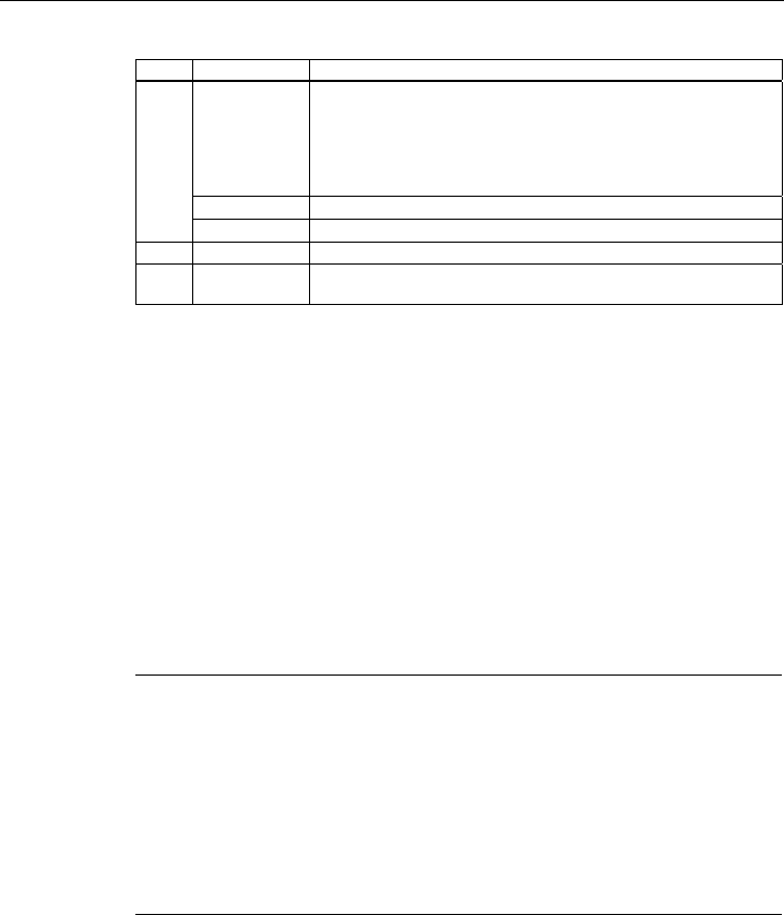
Antennen
Für die Verwendung mit den oben genannten SCALANCE-Geräten sind die nachfolgend
aufgeführten Antennen zugelassen. Die Auswahl einer Antenne können Sie im Web Based
Management oder im Command Line Interface vornehmen.
CLI-Menü: CLI\INTERFACES\WLAN1\ADVANCED> (bzw. \WLAN2\ADVANCED)
Beschreibung
2.3 Abweichende Eigenschaften für Geräte mit anderer Hardware
SCALANCE W788-xPRO/RR / SCALANCE W74x-1PRO/RR
14 Betriebsanleitung (kompakt), Ausgabe 08/2007, A5E00413342-05
Befehl Beschreibung Kommentar
Angabe des Antennentyps.
0 Benutzerdefiniert
1 ANT795-4MR
(Standardantenne) - gain: 3
dBi (2,4 GHz) 5 dBi (5 GHz)
2 ANT795-6MR (inkl.. 5m Kabel)
- gain: 3 dBi (2,4 GHz) 4 dBi (5
GHz)
3 ANT792-8DR mit 5m Kabel -
gain: 10 dBi (2,4 GHz)
4 ANT792-8DR mit 10m Kabel -
gain: 6 dBi (2,4 GHz)
5 ANT792-8DR mit 15m Kabel -
gain: 3 dBi (2,4 GHz)
6 ANT793-8DRmit 5m Kabel -
gain: 14 dBi (5 GHz)
7 ANT792-4DN (RCoax
Antenne) - gain: 4 dBi (2,4
GHz)
8 ANT793-4MN (RCoax
Antenne) - gain: 6 dBi (5 GHz)
anttype [0 ... n]
9 RCoax-Leitung - gain: 0 dBi
(2,4 GHz) 0dBi (5 GHz)
Zum Anzeigen der Liste
geben Sie "anttype ?" ein.
Kompatibilität
Konfigurationsdaten von einem der oben aufgeführten Geräte können Sie auch für einen
SCALANCE W788-xPRO/RR bzw. W74x-1PRO/RR mit einer anderen Bestell-Nummern als
in der obigen Tabelle verwenden.
Admin-Passwort für die USA-Variante
Auch in der USA-Variante ist das Default-Passwort "admin", wenn Sie für den Benutzername
"admin" ausgewählt haben.
Belegung der Energieadern bei einem Hybridkabel 2 x 2 + 4 x 0,34
Farbliche Aderkennzeichnung
(Standard)
Braun Braun Schwarz Schwarz
Funktion 24 V 24 V Masse Masse
Spannungsversorgungs-
Einsatzmodul
1 2 3 4

Beschreibung
2.3 Abweichende Eigenschaften für Geräte mit anderer Hardware
SCALANCE W788-xPRO/RR / SCALANCE W74x-1PRO/RR
Betriebsanleitung (kompakt), Ausgabe 08/2007, A5E00413342-05 15
Belegung der Energieadern bei einem IE FC TP Standard Cable 4 x 2 GP
Farbliche Aderkennzeichnung
(Standard)
Weiß / Blau (1) Blau Weiß /Braun (1) Braun
Funktion 24 V 24 V Masse Masse
Spannungsversorgungs-
Einsatzmodul
1 2 3 4
(1) Weiße Ader des jeweiligen Adernpaars
Erdung
VORSICHT
Beschädigung des Geräts durch Potentialunterschied
Zwischen folgenden Teilen darf kein Potenzialunterschied bestehen, da sonst die Gefahr
besteht, dass das Gerät zerstört wird:
• Potenzial Erde der Spannungsversorgung und dem Erdpotenzial der Antennenerde.
• Potenzial Erde der Spannungsversorgung und einem geerdeten Gehäuse.
• Potenzial Erde der Spannungsversorgung und dem Erdpotenzial des am Industrial
Ethernet angeschlossenen Gerätes (z.B. PC, AS-300, AS-400 usw.).
Legen Sie beide Erdungen auf den gleichen Fundamenterder oder verwenden Sie eine
Potenzialausgleichsleitung.

Beschreibung
2.3 Abweichende Eigenschaften für Geräte mit anderer Hardware
SCALANCE W788-xPRO/RR / SCALANCE W74x-1PRO/RR
16 Betriebsanleitung (kompakt), Ausgabe 08/2007, A5E00413342-05
Sendeleistungen
Tabelle 2-1 Sendeleistung im IEEE 802.11b-Modus (2,4 GHz)
Datenrate [Mb/s] P0 [dBm]
1 18
2 18
5,5 18
11 18
Tabelle 2-2 Sendeleistung im IEEE 802.11g-Modus (2,4 GHz)
Datenrate [Mb/s] P0 [dBm]
6 17
9 17
12 17
18 17
24 17
36 13
48 11
54 10
Tabelle 2-3 Sendeleistung im IEEE 802.11a/h-Modus (5 GHz)
Datenrate [Mb/s] P0 [dBm]
6 17
9 17
12 17
18 17
24 17
36 13
48 11
54 10
Beschreibung
2.3 Abweichende Eigenschaften für Geräte mit anderer Hardware
SCALANCE W788-xPRO/RR / SCALANCE W74x-1PRO/RR
Betriebsanleitung (kompakt), Ausgabe 08/2007, A5E00413342-05 17
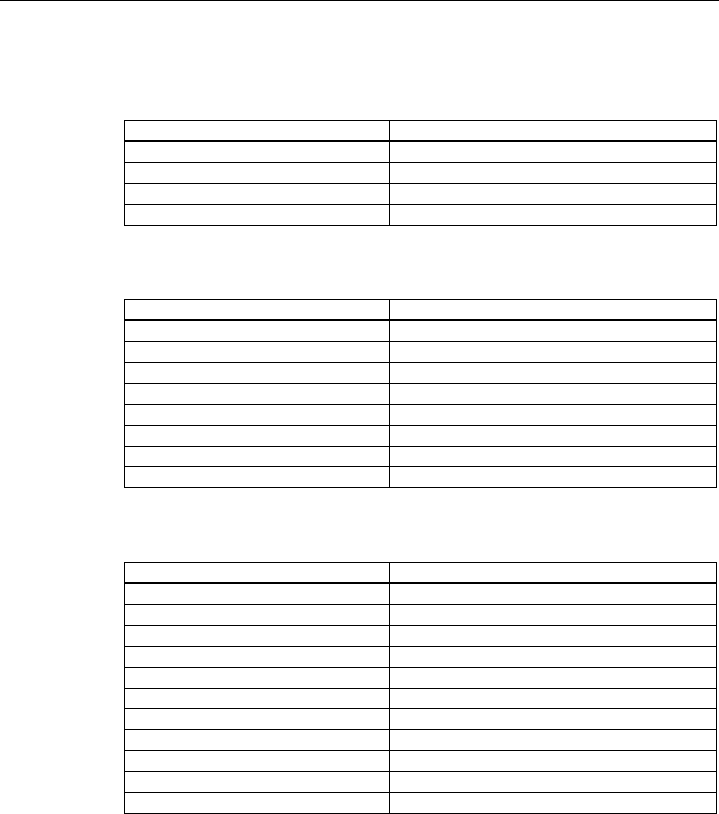
Empfängerempfindlichkeit
Tabelle 2-4 Empfängerempfindlichkeit im IEEE 802.11b-Modus (2,4 GHz)
Datenrate [Mb/s] Pe [dBm]
1 -90
2 -90
5,5 -90
11 -84
Tabelle 2-5 Empfängerempfindlichkeit im IEEE 802.11g-Modus (2,4 GHz)
Datenrate [Mb/s] Pe [dBm]
6 -87
9 -86
12 -85
18 -83
24 -80
36 -76
48 -71
54 -66
Tabelle 2-6 Empfängerempfindlichkeit im IEEE 802.11a/h-Modus (5 GHz)
Datenrate [Mb/s] Pe [dBm]
6 -87
9 -86
12 -85
18 -83
24 -80
36 -76
48 -71
54 -66
72 [*] -73
96 [*] -68
108 [*] -63
[*] Turbo Mode
Beschreibung
2.4 Leuchtdiodenanzeigen
SCALANCE W788-xPRO/RR / SCALANCE W74x-1PRO/RR
18 Betriebsanleitung (kompakt), Ausgabe 08/2007, A5E00413342-05
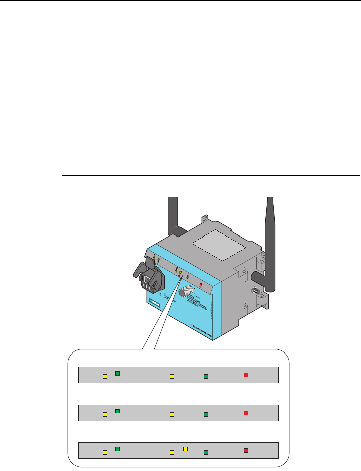
2.4 Leuchtdiodenanzeigen
Informationen über Betriebszustand und Datentransfer des SCALANCE W-788-xPRO/RR bzw.
W74x-1PRO/RR
Auf der Vorderseite des Gehäuses informieren mehrere Leuchtdioden über den
Betriebszustand des SCALANCE W788-xPRO/RR bzw. W74x-1PRO/RR:
Hinweis
Wenn beim Anlauf die LED für das WLAN-Interface nicht grün wird, obwohl es aktiviert ist,
so ist das Interface nicht betriebsbereit (Interface nicht initialisiert).
Das kann insbesondere daran liegen, dass bei Inbetriebnahme eines SCALANCE W788-
xPRO/RR bzw. W74x-1PRO/RR unter dem Gefrierpunkt (Umgebungstemperatur) eine
Wartezeit bis zu 15 Minuten auftreten kann. Das Gerät ist bei der spezifizierten
Umgebungstemperatur betriebsbereit, sobald die LED für das WLAN-Interface grün anzeigt.
P1
L2
R1
R2
L1
F
P1
L2
R1
L1
F
P1
L2
R1
L1
F
SCALANCE W788-1xx
SCALANCE W74x-1xx
SCALANCE W788-2xx
Bild 2-1 Leuchtdiodenanzeige des SCALANCE W788-xPRO/RR bzw.W74x-1PRO/RR

Beschreibung
2.4 Leuchtdiodenanzeigen
SCALANCE W788-xPRO/RR / SCALANCE W74x-1PRO/RR
Betriebsanleitung (kompakt), Ausgabe 08/2007, A5E00413342-05 19
LED Farbe Bedeutung
Gelb Datentransfer über die Ethernet-Schnittstelle (Traffic).
Grün Es besteht eine Verbindung über die Ethernet-Schnittstelle. (Link)
Gelb blinkend PRESET-PLUG erkannt.
Gelb/Grün PRESET-Funktion erfolgreich beendet.
P1
Grün blinkend "Blinken" über PST aktiviert.
L2 Grün Spannungsversorgung über den Hybridstecker X1 (PoE oder
Energiekontakte).
Gelb Datentransfer über die erste WLAN-Schnittstelle.
Grün
W788-xPRO/RR im Access Point-Modus:
Die WLAN-Schnittstelle ist initialisiert und bereit.
W788-xPRO/RR im Client Modus oder W74x-1PRO/RR:
Es besteht eine Verbindung über die erste WLAN-Schnittstelle.
Grün blinkend
W788-xPRO/RR im Access Point-Modus:
Die Kanäle werden "gescannt".
W788-xPRO/RR im Client Modus oder W74x-1PRO/RR:
Der Client sucht die Verbindung mit einem Access Point oder Ad-Hoc
Netzwerk.
Grün schnell
blinkend
W788-xPRO/RR im Access Point-Modus:
Bei 802.11h wird eine Minute nach Primärnutzern auf dem Kanal
gescannt, bevor der Kanal für den Datenverkehr genutzt werden kann.
W788-xPRO/RR im Client Modus oder W74x-1PRO/RR:
Der Client wartet auf die Adopt-MacAdresse durch die Einstellung <Auto
Find Adopt MAC> und ist mit keinem Access Point verbunden..
Grün3x
schnell,1x lang
blinkend
W788-xPRO/RR im Client Modus oder W74x-1PRO/RR:
Der Client wartet auf die Adopt-MacAdresse durch die Einstellung <Auto
Find Adopt MAC> und ist mit einem Access Point verbunden.
Gelb blinkend PRESET-PLUG erkannt.
R1
Gelb/Grün PRESET-Funktion erfolgreich beendet.
Gelb
W788-xPRO/RR im Access Point-Modus:
Datentransfer über die zweite WLAN-Schnittstelle.
W788-xPRO/RR im Client Modus oder W74x-1PRO/RR:
Die LED ist immer aus, da die 2. Schnittstelle im Client-Modus nicht
verfügbar ist.
Grün
W788-xPRO/RR im Access Point-Modus:
Die WLAN-Schnittstelle ist initialisiert und bereit.
W788-xPRO/RR im Client Modus oder W74x-1PRO/RR:
Die LED ist immer aus, da die 2. Schnittstelle im Client-Modus nicht
verfügbar ist.
R2
Grün blinkend
W788-xPRO/RR im Access Point-Modus:
Die Kanäle werden "gescannt".
W788-xPRO/RR im Client Modus oder W74x-1PRO/RR:
Die LED ist immer aus, da die 2. Schnittstelle im Client-Modus nicht
verfügbar ist.
Beschreibung
2.5 C-PLUG
SCALANCE W788-xPRO/RR / SCALANCE W74x-1PRO/RR
20 Betriebsanleitung (kompakt), Ausgabe 08/2007, A5E00413342-05
LED Farbe Bedeutung
Grün schnell
blinkend
W788-xPRO/RR im Access Point-Modus:
Bei 802.11h wird eine Minute nach Primärnutzern auf dem Kanal
gescannt, bevor der Kanal für den Datenverkehr genutzt werden kann.
W788-xPRO/RR im Client Modus oder W74x-1PRO/RR:
Die LED ist immer aus, da die 2. Schnittstelle im Client-Modus nicht
verfügbar ist.
Gelb blinkend PRESET-PLUG erkannt.
Gelb/Grün PRESET-Funktion erfolgreich beendet.
L1 Grün Spannungsversorgung über den M12-Stecker (X2).
F Rot Beim Betrieb des SCALANCE W788-xPRO/RR bzw. W74x-1PRO/RR ist
ein Fehler aufgetreten.
2.5 C-PLUG
Konfigurationsinformation im C-PLUG
Der C-PLUG dient dazu, im Fall eines Geräteaustausches die Konfiguration des alten Geräts
auf das Neugerät zu übertragen. Bei Start des neuen Geräts mit dem C-PLUG läuft dieses
dann automatisch exakt mit der Konfiguration des alten Gerätes an. Ein Ausnahmefall kann
die IP-Konfiguration darstellen, wenn sie per DHCP eingestellt wird und der DHCP-Server
nicht entsprechend umkonfiguriert wurde.
Eine Nachkonfiguration ist erforderlich, wenn Sie WDS oder bei Geräten mit mehr als einer
WLAN-Schnittstelle Redundanz nutzen und dabei die MAC-Adressen und nicht die
sysNamen benutzen. Diese Funktionen basieren dann auf der MAC-Adresse, die sich bei
einem Gerätetausch zwangsläufig ändert.
Hinweis
Im Bezug auf den C-PLUG arbeiten SCALANCE W-700-Geräte in zwei Modi:
• Ohne C-PLUG
Das Gerät speichert die Konfiguration auf dem internen Speicher. Dieser Modus ist aktiv
wenn kein C-PLUG gesteckt ist.
• Mit C-PLUG
Die Konfiguration, die auf dem C-PLUG gespeichert ist, wird über die
Benutzerschnittstellen angezeigt. Der interne Speicher wird in diesem Modus weder
gelesen noch beschrieben. Bei Änderungen der Konfiguration speichert das Gerät die
Konfiguration direkt auf dem C-PLUG. Dieser Modus ist aktiv, sobald ein C-PLUG
gesteckt ist. Sobald das Gerät mit gestecktem C-PLUG gestartet wird, läuft der
SCALANCE W-700 mit den Konfigurationsdaten auf dem C-PLUG an.

Beschreibung
2.6 Reset-Taster
SCALANCE W788-xPRO/RR / SCALANCE W74x-1PRO/RR
Betriebsanleitung (kompakt), Ausgabe 08/2007, A5E00413342-05 21
2.6 Reset-Taster
Funktionen des Reset-Tasters
Der Reset Taster befindet sich unter der Verschluss-Schraube auf der Rückseite des
Gehäuses direkt neben dem C-PLUG und hat mehrere Funktionen:
● Neustart des Geräts
Um einen Neustart des Geräts durchzuführen, drücken Sie den Reset Taster.
● Laden einer neuen Firmware
Falls das reguläre Vorgehen über den Menüpunkt Load & Save des Web Based
Managements nicht funktioniert, kann der Reset-Taster zum Laden einer neuen Firmware
genutzt werden. Dieser Fall kann eintreten, wenn es während des regulären Firmware-
Updates zu einem Spannungsausfall kam.
● Wiederherstellen der Default Parameter (Auslieferungszustand, Factory default)
● Übernahme der Konfigurationsdaten aus dem PRESET-PLUG.

Beschreibung
2.7 Biologische Verträglichkeit
SCALANCE W788-xPRO/RR / SCALANCE W74x-1PRO/RR
22 Betriebsanleitung (kompakt), Ausgabe 08/2007, A5E00413342-05
2.7 Biologische Verträglichkeit
Elektromagnetische Felder und Gesundheit
Hinsichtlich der Frage, ob elektromagnetische Felder (zum Beispiel im Zusammenhang mit
Industrial Wireless LAN) die menschliche Gesundheit gefährden können, verweisen wir auf
eine Publikation der BITKOM (Bundesverband Informationswirtschaft, Telekommunikation
und neue Medien e. V.), Stand Dezember 2003:
"Für WLAN-Geräte gelten die gleichen Vorschriften zum Schutz vor gesundheitlichen
Beeinträchtigungen wie für alle anderen Funkanwendungen auch. Diese Vorschriften
beruhen auf den Schutzkonzepten der ICNIRP1 bzw. der entsprechenden
EU-Ratsempfehlung.
Die unabhängige deutsche Strahlenschutzkommission (SSK) hat im Auftrag des BMU
(Bundesministeriums für Umwelt) den Stand der Wissenschaft hinsichtlich möglicher
Gefahren - thermisch und nicht thermisch - durch elektromagnetische Felder ermittelt und
äußert sich wie folgt2:
'Die SSK kommt zu dem Schluss, dass auch nach der Bewertung der neueren
wissenschaftlichen Literatur keine neuen wissenschaftlichen Erkenntnisse im Hinblick auf
nachgewiesene Gesundheitsbeeinträchtigungen vorliegen, die Zweifel an der
wissenschaftlichen Bewertung aufkommen lassen, die den Schutzkonzepten der ICNIRP
bzw. der EU-Ratsempfehlung zugrunde liegt.'
Darüber hinaus stellt die SSK fest, dass unterhalb der bestehenden Grenzwerte auch kein
wissenschaftlicher Verdacht auf gesundheitliche Risiken besteht.
Diese Bewertung stimmt mit denen anderer nationaler und internationaler wissenschaftlicher
Kommissionen sowie der WHO (www.who.int/emf) überein.
Dementsprechend und angesichts der Tatsache, dass WLAN-Geräte die wissenschaftlich
fundierten Grenzwerte deutlich unterschreiten, gehen von den elektromagnetischen Feldern
von WLAN-Produkten keine gesundheitlichen Gefahren aus.
1 Internationale Kommission zum Schutz vor Nicht-Ionisierender Strahlung
2 'Grenzwerte und Vorsorgemaßnahmen zum Schutz der Bevölkerung vor
elektromagnetischen Feldern', Empfehlung der Strahlenschutzkommission mit
wissenschaftlicher Begründung, Heft 29, 2001."
Weitere Informationen zu diesem Thema finden Sie im Internet unter folgender URL:
www.bitkom.org

SCALANCE W788-xPRO/RR / SCALANCE W74x-1PRO/RR
Betriebsanleitung (kompakt), Ausgabe 08/2007, A5E00413342-05 23
Montage 3
3.1 Befestigung des Gehäuses
Wandmontage oder Profilschiene
Es gibt zwei Möglichkeiten, das Gehäuse zu befestigen:
● Wandmontage
Verwenden Sie die Gehäusebohrungen für eine Verschraubung an der Wand oder auf
einer horizontalen Fläche.
● Profilschienenmontage
Montieren Sie den SCALANCE W788-xPRO/RR bzw. W74x-1PRO/RR auf ein 90 mm
langes, senkrecht montiertes Stück Profilschiene (S7-300). Die Profilschiene dient in
diesem Fall als Adapter zwischen Wand und SCALANCE W788-xPRO/RR bzw. W74x-
1PRO/RR. Soll der SCALANCE W788-xPRO/RR bzw. W74x-1PRO/RR zusammen mit
einem PS791-1PRO montiert werden, ist eine 150 mm lange Profilschiene erforderlich.
Sorgen Sie für eine geeignete Zugentlastung der Anschlusskabel.
VORSICHT
Frühzeitige Alterung des Geräts und der Verkabelung durch UV-Strahlen
Schützen Sie das Gerät durch eine geeignete Abschattung gegen direktes Sonnenlicht. Sie
vermeiden so eine unerwünschte Erwärmung des Geräts und verhindern eine frühzeitige
Alterung von Gerät und Verkabelung. Beim Betrieb des SCALANCE W im Freien ist eine
UV-geschützte Montage zwingend. Durch UV-Strahlung kann sich die Frontplatte des
SCALANCE W788-xPRO/RR bzw. W74x-1PRO/RR verfärben. Eine Verfärbung der
Frontplatte beeinträchtigt die mechanische Stabilität des Geräts jedoch nicht. Zudem darf
das Gerät keinem Dauerregen ausgesetzt werden(Schutz durch Überdachung).
Bevorzugen Sie eine Überdachung aus Kunststoff, weil Metall die Ausbreitung von
Funkwellen beeinträchtigt.
Hinweis
Der Mindestabstand zu Leuchtröhren sollte 0,5 m betragen. Für den Schaltschrankeinbau
empfehlen wir, Relais nicht auf der gleichen und auf den direkt benachbarten
Montageschienen zu montieren.
Montage
3.2 Bohrbild SCALANCE W788-xPRO/RR und SCALANCE W74x-1PRO/RR
SCALANCE W788-xPRO/RR / SCALANCE W74x-1PRO/RR
24 Betriebsanleitung (kompakt), Ausgabe 08/2007, A5E00413342-05
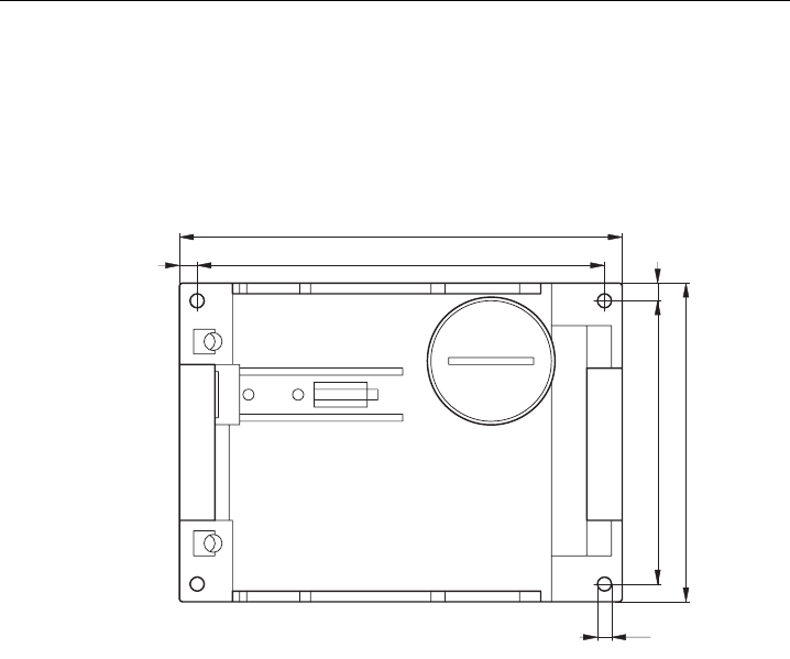
3.2 Bohrbild SCALANCE W788-xPRO/RR und SCALANCE W74x-
1PRO/RR
Bohrungen für die Wandbefestigung
125
115
4
80
90
5
5
SCALANCE W788-xPRO/RR / SCALANCE W74x-1PRO/RR
Betriebsanleitung (kompakt), Ausgabe 08/2007, A5E00413342-05 25
Anschließen 4
4.1 Verkabelung für Spannungsversorgung und Ethernet
Geeignete Kabel
Es gibt folgende Kabelvarianten für den Anschluss eines SCALANCE W788-xPRO/RR bzw.
SCALANCE W74x-1PRO/RR an die Spannungsversorgung und das Ethernet:
● IE Hybridcable 2 x 2 + 4 x 0,34 (Best.-Nr. 6XV1870-2J)
Die beiden Datenleitungspaare sind separat geschirmt. Dieses Kabel eignet sich
besonders gut für die Montage an den IE IP 67 Hybrid-Stecker.
● IE FC TP Standard Cable 4 x 2 GP (Best.-Nr. 6XV1870-2E)
Bei diesem Kabeltypen sind jeweils zwei Leitungen miteinander verdrillt. Alle vier
Leitungspaare sind in einer gemeinsamen Schirmung untergebracht.
● 2 x 2 IE Leitung, die optionale Spannungsversorgung (18 - 48 V DC) erfolgt über M12-
Stecker.
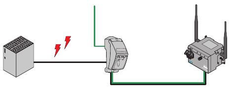
Kabelauswahl und Störbelastung
Maßgeblich für die Auswahl des Kabeltyps ist auch die elektromagnetische Störbelastung,
die auf zuführende Stromleitungen zwischen Spannungsversorgung und FC RJ45 Modular
Outlet wirkt. Wegen der separaten Schirmung der Datenleitungen wirken sich beim
Hybridkabel solche Störungen weniger stark auf die Datenübertragung aus als beim TP
Standard Cable oder dem TP Flexible Cable.
AB C
Bild 4-1 Verkabelung eines SCALANCE W788-xPRO/RR mit elektromagnetischer
Störeinkopplung zwischen Spannungsversorgung und Modular Outlet
A Spannungsversorgung
B FC RJ45 Modular Outlet mit Power Insert
C SCALANCE W788-xPRO/RR
Anschließen
4.2 Blitzschutz, Versorgungsspannung und Erdung
SCALANCE W788-xPRO/RR / SCALANCE W74x-1PRO/RR
26 Betriebsanleitung (kompakt), Ausgabe 08/2007, A5E00413342-05
4.2 Blitzschutz, Versorgungsspannung und Erdung
Hinweise zum Blitzschutz
WARNUNG
Lebensgefahr durch Blitzschlag
Antennen im Außenbereich müssen sich im Fangbereich eines Blitzableiters befinden.
Stellen Sie sicher, dass für alle von außen eingeführten leitfähigen Systeme die Möglichkeit
eines Blitzschutz-Potenzialausgleichs gegeben ist.
Beachten Sie bei der Umsetzung Ihres Blitzschutzkonzepts unbedingt die Anforderungen
der Normen VDE 0182 bzw. IEC 62305.
Ein geeignetes Blitzschutzelement ist im Zubehörprogramm von SIMATIC NET Industrial
WLAN verfügbar:
Blitzschutzelement LP798-1N (Bestell-Nr. 6GK5798-2LP00-2AA6)
WARNUNG
Lebensgefahr durch Blitzschlag
Der Einbau des genannten Blitzschutzelements zwischen einer Antenne und einem
SCALANCE W-700 stellt noch keinen ausreichenden Schutz gegen Blitzeinschlag dar. Das
Blitzschutzelement LP798-1N ist nur im Rahmen eines umfassenden Blitzschutzkonzepts
funktionsfähig. Wenden Sie sich an einen qualifizierten Fachbetrieb, wenn Sie dazu Fragen
haben.
Hinweis
Die Anforderungen nach EN61000-4-5, Surge Prüfung auf Spannungsversorgungsleitungen,
werden bei DC 12 - 24 V und DC 48 V nur erfüllt bei Einsatz eines Blitzductors:
DC 12 - 24 V: VT AD 24V Art. Nr. 918 402
DC 48 V: Art.-Nr. 919 545 und 919 506 (Halter)
Hersteller: DEHN+SÖHNE GmbH+Co.KG, Hans Dehn Str. 1, Postfach 1640, D-
92306 Neumarkt

Anschließen
4.2 Blitzschutz, Versorgungsspannung und Erdung
SCALANCE W788-xPRO/RR / SCALANCE W74x-1PRO/RR
Betriebsanleitung (kompakt), Ausgabe 08/2007, A5E00413342-05 27
Sicherheitskleinspannung
WARNUNG
Lebensgefahr durch Überspannung, Brandgefahr
Die Geräte SCALANCE W-700 sind für den Betrieb mit einer direkt anschließbaren
Sicherheitskleinspannung oder mit den als Zubehör erhältlichen
Stromversorgungsadaptern (nur für das Gerät SCALANCE W786-xPRO verfügbar)
ausgelegt. Deshalb dürfen an die Versorgungsanschlüsse nur Sicherheitskleinspannungen
(SELV) mit begrenzter Leistung (LPS) nach IEC950/EN60950/VDE0805 angeschlossen
werden (Ausnahme: Stromversorgungsadapter für AC 110 - 230 V für den SCALANCE
W786-xPRO).
Treffen Sie Maßnahmen, um transiente Überspannungen von mehr als 40% der Nenn-
spannung zu verhindern. Das ist gewährleistet, wenn Sie die Geräte ausschließlich mit
SELV (Sicherheitskleinspannung) betreiben.
Das Netzteil für die Versorgung eines SCALANCE W-700 muss NEC Class 2
(Anforderungen der Klasse 2 für Stromversorgungen der "National Electrical Code, table 11
(b)") oder SELV mit LPS (Limited Power Source) EN 60950-1 entsprechen. Bei einem
Aufbau mit redundanter Spannungsversorgung (zwei getrennte Spannungsversorgungen)
müssen beide Spannungsversorgungen diese Anforderungen erfüllen.
Ausnahmen:
• Die Versorgung durch PELV (entsprechend DIN VDE 0100-410 bzw. IEC 60364-4-41)
ist ebenfalls zulässig, sofern die erzeugte Nennspannung die Spannungsgrenzen AC 25
V oder DC 60 V nicht überschreitet.
Erdung
VORSICHT
Beschädigung des Geräts durch Potentialunterschied
Um eine Beeinflussung durch elektromagnetische Störungen zu vermeiden, sollte das
Gerät geerdet montiert werden. Zwischen folgenden Teilen darf kein Potenzialunterschied
bestehen, da sonst das Gerät oder angeschlossene weitere Geräte möglicherweise zerstört
werden:
• Gehäuse des SCALANCE W-700 und dem Erdpotential der Antenne.
• Gehäuse des SCALANCE W-700 und dem Erdpotential eines über Ethernet
angeschlossenen Gerätes.
• Gehäuse des SCALANCE W-700 und der Schirmauflage des angeschlossenen
Ethernet-Kabels.
Legen Sie beide Erdungen auf den gleichen Fundamenterder oder verwenden Sie eine
Potenzialausgleichsleitung.

Anschließen
4.2 Blitzschutz, Versorgungsspannung und Erdung
SCALANCE W788-xPRO/RR / SCALANCE W74x-1PRO/RR
28 Betriebsanleitung (kompakt), Ausgabe 08/2007, A5E00413342-05
Unterbrechung der Stromversorgung
VORSICHT
Beschädigung der Ethernet-Schnittstelle
Wiederholtes schnelles Ziehen und Stecken des Ethernet-Kabels mit Power-over-Ethernet-
Speisung bei gleichzeitiger redundanter Stromversorgung kann zur Beschädigung der
Ethernet-Schnittstelle führen.
Vermeiden Sie wiederholtes Ziehen und Stecken des Ethernet-Kabels bei Power-over-
Ethernet-Speisung und redundanter Stromversorgung.

Anschließen
4.3 Geeignete Antennenleitungen und Antennen für den SCALANCE W-700
SCALANCE W788-xPRO/RR / SCALANCE W74x-1PRO/RR
Betriebsanleitung (kompakt), Ausgabe 08/2007, A5E00413342-05 29
4.3 Geeignete Antennenleitungen und Antennen für den SCALANCE W-
700
Antennenanschluss: Anschlusskabel N-Connect/R-SMA
Zum direkten Anschluss einer Antenne an einen SCALANCE W-700 ist das
N-Connect/R-SMA Male/Male Flexible Connection Cable als Zubehör lieferbar.
Länge in m Bestellnummer
1
2
5
10
6XV1875-5CH10
6XV1875-5CH20
6XV1875-5CH50
6XV1875-5CN10
Antennenanschluss: Anschlusskabel N-Connect/ N-Connect
Zur Verbindung einer Antenne mit dem Blitzschutzelement LP798-1N ist das
N-Connect/N-Connect Male/Male Flexible Connection Cable als Zubehör lieferbar.
Länge in m Bestellnummer
1
2
5
10
6XV1875-5CH10
6XV1875-5CH20
6XV1875-5CH50
6XV1875-5CN10
Für IWLAN-Geräte, die sich in einem Schaltschrank befinden, gibt es eine
Schaltschrankdurchführung mit entsprechenden Leitungen. Detailinformationen finden Sie
im Katalog IK PI.

Anschließen
4.3 Geeignete Antennenleitungen und Antennen für den SCALANCE W-700
SCALANCE W788-xPRO/RR / SCALANCE W74x-1PRO/RR
30 Betriebsanleitung (kompakt), Ausgabe 08/2007, A5E00413342-05
Antennen
Für die Verwendung mit einem SCALANCE W-700 sind folgende Antennen freigegeben:
Typ Eigenschaften Bestell-Nr.
ANT795-6MN Omniantenne 2,4 / 5GHz,
Deckenmontage
6GK5795-6MN00-0AA6
ANT792-6MN Omniantenne 2,4 GHz,
Wandmontage
6GK5792-6MN00-0AA6
ANT793-6MN Omniantenne 5 GHz,
Wandmontage
6GK5793-6MN00-0AA6
ANT792-8DN Richtantenne 2,4 GHz,
Wandmontage
6GK5792-8DN00-0AA6
ANT793-8DN Richtantenne 5 GHz,
Wandmontage
6GK5793-8DN00-0AA6
ANT795-6DN Richtantenne 2,4 / 5 GHz,
Wandmontage
6GK5795-6DN00-0AA6
ANT795-4MR Omniantenne 2,4 / 5GHz,
Montage direkt an einem
SCALANCE W788-xPRO/RR
oder W74x-1PRO/RR
6GK5795-4MR00-0AA6
ANT795-4MS Omniantenne 2,4 / 5GHz,
Montage direkt an einem
SCALANCE W788-xPRO/RR
bzw. W784-1xx oder W74x-
1PRO/RR bzw. W74x-1
6GK5795-4MS00-0AA6
ANT792-4DN RCoax-Antenne 2,4 GHz 6GK5792-4DN00-0AA6
ANT793-4MN RCoax-Antenne 5 GHz 6GK5793-4MN00-0AA6

Anschließen
4.4 Anschlüsse für externe Antennen und Spannungsversorgung
SCALANCE W788-xPRO/RR / SCALANCE W74x-1PRO/RR
Betriebsanleitung (kompakt), Ausgabe 08/2007, A5E00413342-05 31
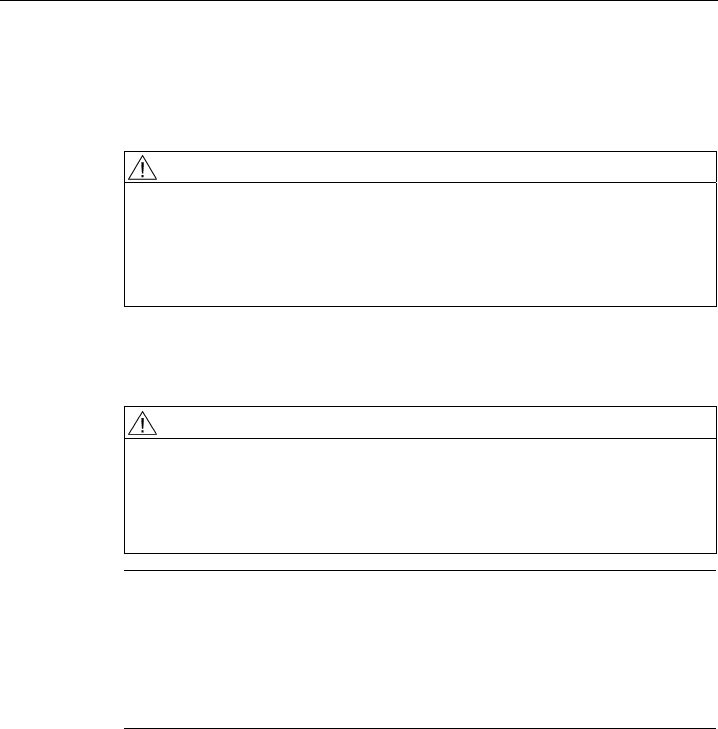
4.4 Anschlüsse für externe Antennen und Spannungsversorgung
Hybrid-Buchse und M12-Stecker
Der Anschluss des SCALANCE W788-xPRO / W788-xRR / W74x-1xx an ein Ethernet erfolgt
über eine Hybridbuchse auf der Vorderseite des Gehäuses (Position A in der Abbildung).
Diese Schnittstelle verfügt auch über Kontakte für die Betriebsspannung.
VORSICHT
Zugentlastung für das Hybridkabel
Stellen Sie sicher, dass die Hybridbuchse von Zugkräften in Längs- oder Querrichtung
entlastet ist. Kräfte auf die Buchse können auch durch die Gewichtskraft des Hybridkabels
entstehen, beispielsweise wenn Sie den SCALANCE W in einer größeren Höhe anbringen.
Hinweis
Schutzkappe für die Hybridbuchse
Wird die Hybridbuchse nicht verwendet, muss sie mit einer Schutzkappe abgedeckt werden,
andernfalls ist die Schutzart IP 65 nicht gegeben. Eine geeignete Schutzkappe ist als
Zubehörteil (Bestell-Nr. 6ES7194-1JB10-0XA0) erhältlich. Ebenfalls muss bei
Nichtverwendung des M12-Steckers die mitgelieferte Schutzkappe verwendet werden, um
die Schutzart IP 65 aufrecht zu erhalten.
Anschließen
4.4 Anschlüsse für externe Antennen und Spannungsversorgung
SCALANCE W788-xPRO/RR / SCALANCE W74x-1PRO/RR
32 Betriebsanleitung (kompakt), Ausgabe 08/2007, A5E00413342-05
A
BC
D
Bild 4-2 Anschlüsse des SCALANCE W788-xPRO/RR bzw. W74x-1PRO/RR. Die zusätzlichen
Antennenanschlüsse (Position C) sind nur bei den Typen W788-2PRO und W788-2RR
vorhanden.
Alternativ oder zusätzlich können Sie für die Spannungsversorgung auch den M12-Stecker
(Position B in der vorangegangenen Abbildung) nutzen.
Zusätzliche Antennen können Sie beim SCALANCE W788-2PRO und beim
SCALANCE W788-2RR mittels Antennenanschlusskabel an den Gehäuseseiten anbringen
(Position C in der vorangegangenen Abbildung). Beim Einbau des SCALANCE W788-
xPRO/RR bzw. W74x-1PRO/RR in einen Schaltschrank müssen Sie auf Grund
eingeschränkter Kommunikation die Antennen (Position D in der Abbildung) abschrauben.
Die Verbindung erfolgt in diesem Fall durch abgesetzte Antennen, die Sie außerhalb des
Schaltschranks anbringen müssen. Auf der Frontseite ist auch eine Kennzeichnung der
Antennenanschlüssen angebracht. Die Anschlüsse A befinden sich auf der rechten Seite,
die Anschlüsse B auf der linken Seite.
Für die Verbindung zwischen SCALANCE W788-xPRO/RR bzw. W74x-1PRO/RR und
abgesetzter Antenne werden von SIMATIC NET passende Anschlusskabel angeboten.
Detailinformationen finden Sie im Kapitel "Geeignete Antennenleitungen und Antennen für
den SCALANCE W-700".
Anschließen
4.4 Anschlüsse für externe Antennen und Spannungsversorgung
SCALANCE W788-xPRO/RR / SCALANCE W74x-1PRO/RR
Betriebsanleitung (kompakt), Ausgabe 08/2007, A5E00413342-05 33
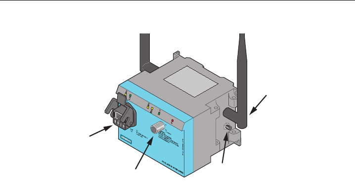
Zuordnung von Schnittstellen und Anschlüssen
Hinweis
Der Abstand zwischen dem Antennenpaar für die erste und die zweite WLAN-Schnittstelle
muss mindestens 0,5 m betragen.
ACHTUNG
Abschlusswiderstand
Jede WLAN-Schnittstelle verfügt über zwei Antennenanschlüsse. Wenn Sie nur einen
Anschluss nutzen, müssen Sie den zweiten Anschluss mit einem Abschlusswiderstand
versehen, um die einwandfreie Funktion des SCALANCE W788-xPRO/RR bzw. W74x-
1PRO/RR zu gewährleisten.
Die folgenden Abbildung zeigt die Lage der Buchsen für die einzelnen Schnittstellen:
SIEMENS
A2
A1
SCALANCE W788-2PRO
S VP JM 123 44-72-22
ML2
X1
P1 FOR LAN ONLY
L2 DC 24V
WARNING:
EXPLOSION HAZARD.
DO NOT CONNECT EQUIPMENT
UNLESS AREA IS KNOWN TO BE
NONHAZARDOUS
M
X2
L1 24VDC
788-1ST00-2AA6
A2 ANTENNA A1
B2
B1
Bild 4-3 Belegung der Antennenanschlüsse des SCALANCE W788-xPRO/RR bzw. W74x-
1PRO/RR. Die Antennenanschlüsse A2 und B2 sind nur bei den Typen W788-2PRO und
W788-2RR vorhanden.
Anschließen
4.5 Montage IE Hybridcable 2 x 2 + 4 x 0,34 an einen IE IP 67 Hybrid-Stecker
SCALANCE W788-xPRO/RR / SCALANCE W74x-1PRO/RR
34 Betriebsanleitung (kompakt), Ausgabe 08/2007, A5E00413342-05
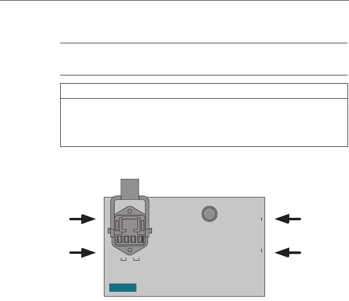
4.5 Montage IE Hybridcable 2 x 2 + 4 x 0,34 an einen IE IP 67 Hybrid-
Stecker
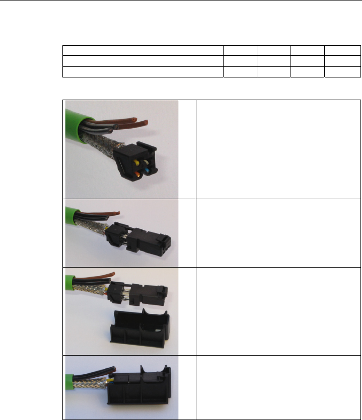
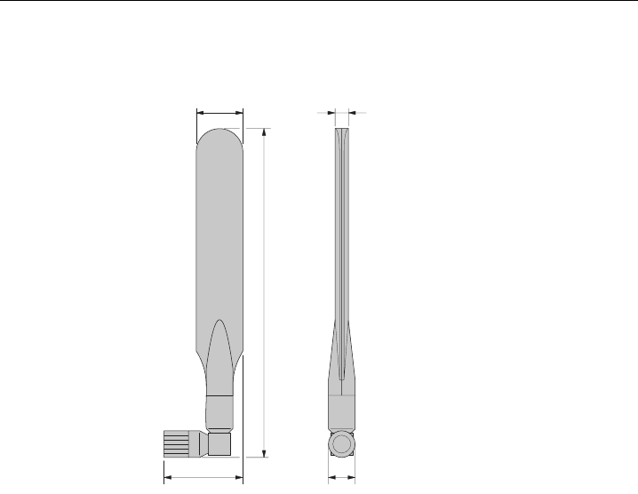
Vorgehen
Entfernen Sie die zwei innere Schalen des
Universaldichtringes, um diesen auf den Durchmesser
des Kabels anzupassen.
Schieben Sie Verschraubung, Druckscheibe,
angepassten Universaldichtring und das Gehäuse über
den Kabelmantel.
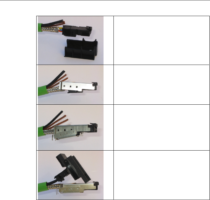
25 mm
19 mm 11 mm
Entfernen Sie den Kabelmantel und das Schirmgeflecht
auf folgenden Längen:
• 25 mm für die Energieadern.
• 30 mm für die Datenadern, davon das Schirmgeflecht
um 11 mm kürzen.
Schneiden Sie das Füllmaterial auf Höhe des
Kabelmantels ab.
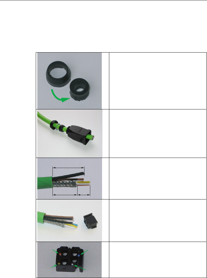
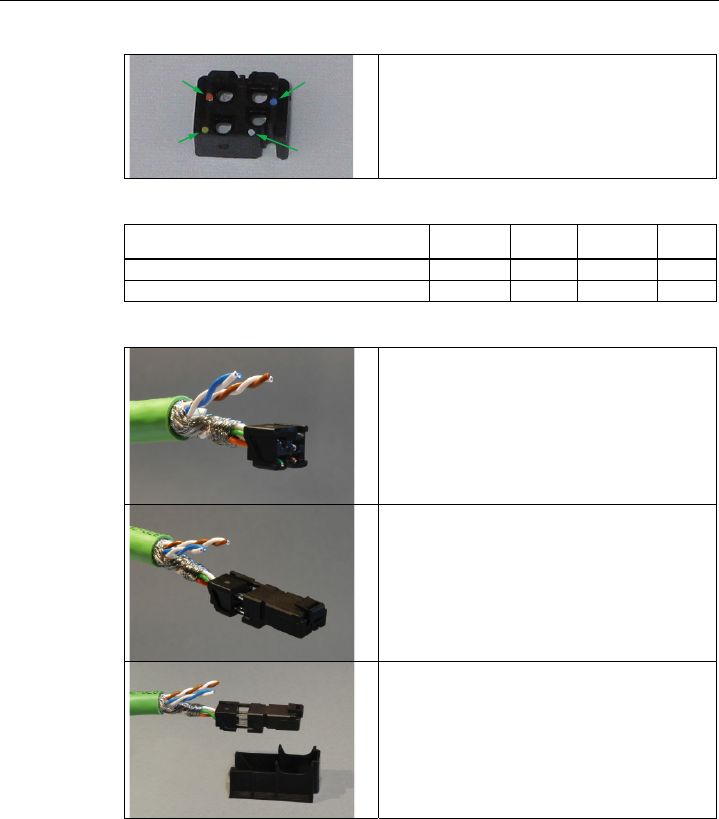
Formen Sie die Datenadern entsprechend den Farb-
Codes auf dem Spleißelement aus. Die nachfolgende
Tabelle zeigt die Belegung der Datenadern.
Kontakt 6
(Blau)
Kontakt 1
(Gelb)
Kontakt 2
(Orange)
Kontakt 3
(Weiß)
Kontakt- und Farbbelegung des Spleißelementes.
Anschließen
4.5 Montage IE Hybridcable 2 x 2 + 4 x 0,34 an einen IE IP 67 Hybrid-Stecker
SCALANCE W788-xPRO/RR / SCALANCE W74x-1PRO/RR
Betriebsanleitung (kompakt), Ausgabe 08/2007, A5E00413342-05 35
Farbliche Aderkennzeichnung (Standard) Weiß Blau Gelb Orange
Farbliche Steckerkennzeichnung (Siemens IE) Weiß Blau Gelb Orange
Siemens IE FC RJ45-Steckdose (Referenz) 3 6 1 2
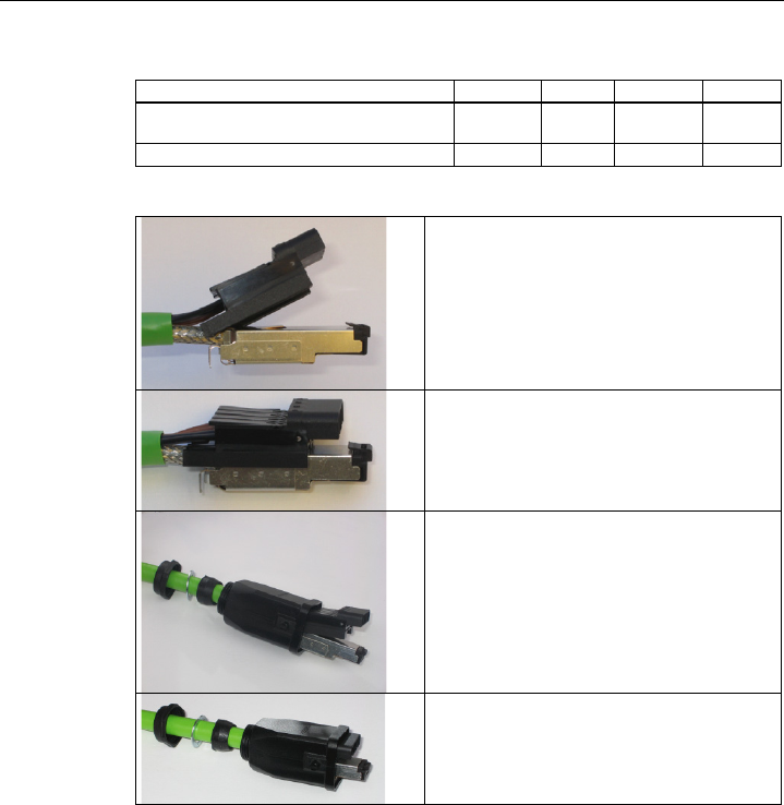
Fügen Sie die Datenadern gleichzeitig bis zum Ende in
das Spleißelement ein.
Fügen Sie das Spleißelement und das RJ 45-
Datenmodul zusammen, bis sie einrasten.
Legen Sie das Datenmodul und das Spleißelement in
das beigefügte IDC-Montagewerkzeug ein.
Pressen Sie das Datenmodul und IDC-
Montagewerkzeug zusammen um die
Schneidklemmenverbindung herzustellen.
Anschließen
4.5 Montage IE Hybridcable 2 x 2 + 4 x 0,34 an einen IE IP 67 Hybrid-Stecker
SCALANCE W788-xPRO/RR / SCALANCE W74x-1PRO/RR
36 Betriebsanleitung (kompakt), Ausgabe 08/2007, A5E00413342-05
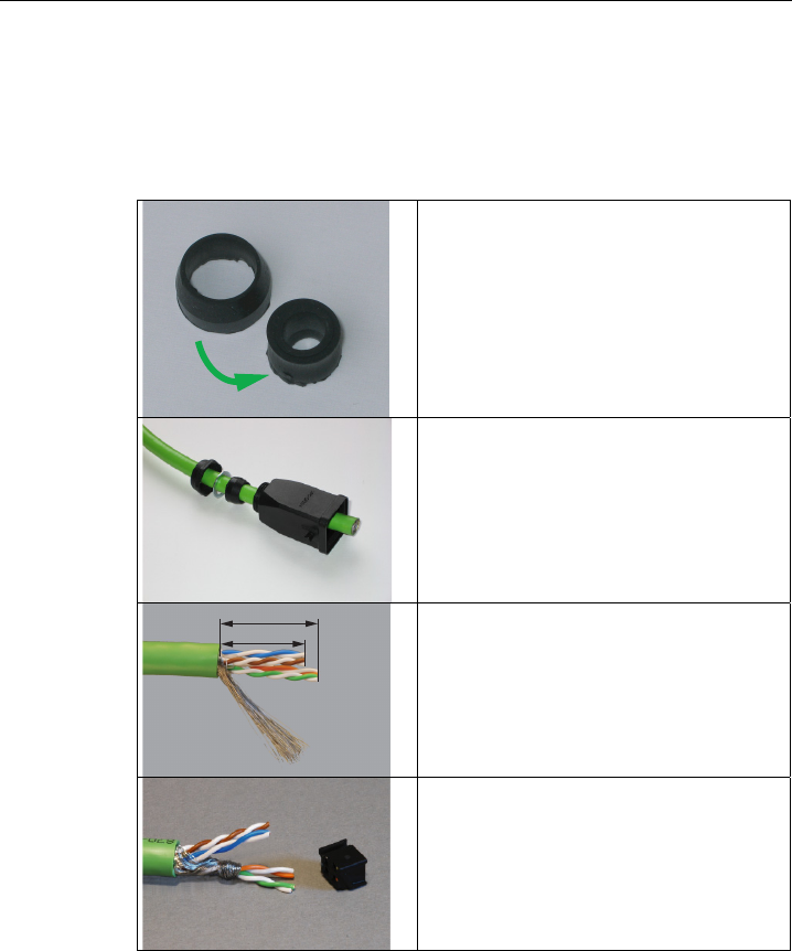
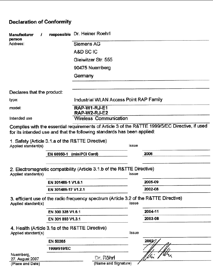
Entnehmen Sie das konfektionierte Datenmodul aus
dem IDC-Montagewerkzeug.
Setzen Sie das obere Schirmblech auf und drücken
Sie es über den Kabelschirm.
Setzen Sie das untere Schirmblech auf und fügen Sie
es mit dem oberen Schirmblech zusammen, bis es mit
einem hörbaren "Klick" einrastet.
Formen Sie die Energieadern aus und fügen Sie sie
bis zum Ende in die Scharnierelemente des
Isolierkörpers ein.
Die nachfolgende Tabelle zeigt die Belegung der
Energieadern.
Anschließen
4.5 Montage IE Hybridcable 2 x 2 + 4 x 0,34 an einen IE IP 67 Hybrid-Stecker
SCALANCE W788-xPRO/RR / SCALANCE W74x-1PRO/RR
Betriebsanleitung (kompakt), Ausgabe 08/2007, A5E00413342-05 37
Farbliche Aderkennzeichnung (Standard) Braun Braun Schwarz Schwarz
Funktion 24 V 48 V PoE Masse Masse
PoE
Spannungsversorgungs-Einsatzmodul 1 2 3 4
Pressen Sie jedes Scharnierelement einzeln mit dem
integrierten IDC-Kontakt zusammen.
Schieben Sie das Gehäuse über das montierte
Datenmodul und den Isolierkörper bis es mit einem
hörbaren "Klick" einrastet.
Ziehen Sie die Kabelverschraubung fest. Wir
empfehlen einen Gabelschlüssel mit einer
Schlüsselweite von 21 mm.
Anschließen
4.6 Montage IE FC TP Standard Cable 4 x 2 GP an einen IE IP 67 Hybrid-Stecker
SCALANCE W788-xPRO/RR / SCALANCE W74x-1PRO/RR
38 Betriebsanleitung (kompakt), Ausgabe 08/2007, A5E00413342-05
4.6 Montage IE FC TP Standard Cable 4 x 2 GP an einen IE IP 67 Hybrid-
Stecker
Vorgehen
Entfernen Sie die zwei innere Schalen des
Universaldichtringes, um diesen auf den Durchmesser
des Kabels anzupassen.
Schieben Sie Verschraubung, Druckscheibe,
angepassten Universaldichtring und das Gehäuse über
den Kabelmantel.
25 mm
30 mm
Entfernen Sie den Kabelmantel und das Schirmgeflecht
auf folgenden Längen:
• 25 mm für die Energieadern
• 30 mm für die Datenadern
Für eine gute Abschirmung muss das Schirmgeflecht
mindestens 30 mm lang sein.
Formen Sie die Datenadern entsprechend den Farb-
Codes auf dem Spleißelement aus. Die nachfolgende
Tabelle zeigt die Belegung der Datenadern.
Wickeln Sie das Schirmgeflecht um die Datenadern.
Dadurch erhält die Schirmung des Kabels Kontakt zum
später zu installierenden Schirmblech des
Spleißelementes.
Anschließen
4.6 Montage IE FC TP Standard Cable 4 x 2 GP an einen IE IP 67 Hybrid-Stecker
SCALANCE W788-xPRO/RR / SCALANCE W74x-1PRO/RR
Betriebsanleitung (kompakt), Ausgabe 08/2007, A5E00413342-05 39
Kontakt 6
(Blau)
Kontakt 1
(Gelb)
Kontakt 2
(Orange)
Kontakt 3
(Weiß)
Kontakt- und Farbbelegung des Spleißelementes.
Farbliche Aderkennzeichnung Standardkabel Weiß /
Orange *
Orange Weiß /
Grün *
Grün
Farbliche Steckerkennzeichnung (Siemens IE) Weiß Blau Gelb Orange
Siemens IE FC RJ45-Steckdose (Referenz) 3 6 1 2
* Weiße Ader des jeweiligen Adernpaars.
Fügen Sie die Datenadern gleichzeitig bis zum Ende in
das Spleißelement ein.
Fügen Sie das Spleißelement und das RJ 45-
Datenmodul zusammen, bis sie einrasten.
Legen Sie das Datenmodul und das Spleißelement in
das beigefügte IDC-Montagewerkzeug ein.

Anschließen
4.6 Montage IE FC TP Standard Cable 4 x 2 GP an einen IE IP 67 Hybrid-Stecker
SCALANCE W788-xPRO/RR / SCALANCE W74x-1PRO/RR
40 Betriebsanleitung (kompakt), Ausgabe 08/2007, A5E00413342-05
Pressen Sie das Datenmodul und IDC-
Montagewerkzeug zusammen um die
Schneidklemmenverbindung herzustellen.
Entnehmen Sie das konfektionierte Datenmodul aus
dem IDC-Montagewerkzeug.
Setzen Sie das obere Schirmblech auf und drücken Sie
es über den Kabelschirm.
Setzen Sie das untere Schirmblech auf und fügen Sie es
mit dem oberen Schirmblech zusammen, bis es mit
einem hörbaren "Klick" einrastet.
Formen Sie die Energieadern aus und fügen Sie sie bis
zum Ende in die Scharnierelemente des Isolierkörpers
ein.
Die nachfolgende Tabelle zeigt die Belegung der
Energieadern.

Anschließen
4.6 Montage IE FC TP Standard Cable 4 x 2 GP an einen IE IP 67 Hybrid-Stecker
SCALANCE W788-xPRO/RR / SCALANCE W74x-1PRO/RR
Betriebsanleitung (kompakt), Ausgabe 08/2007, A5E00413342-05 41
Farbliche Aderkennzeichnung (Standard) Weiß /
Blau *
Blau Weiß /
Braun *
Braun
Funktion 24 V 48 V PoE Masse Masse
PoE
Spannungsversorgungs-Einsatzmodul 1 2 3 4
* Weiße Ader des jeweiligen Adernpaars.
Pressen Sie jedes Scharnierelement einzeln mit dem
integrierten IDC-Kontakt zusammen.
Empfehlung: Verwenden Sie einen kleinen
Schlitzschraubendreher (max. 3,5 mm) als Hebel.
Schieben Sie das Gehäuse über das montierte
Datenmodul und den Isolierkörper bis es mit einem
hörbaren "Klick" einrastet.
Ziehen Sie die Kabelverschraubung fest. Wir empfehlen
einen Gabelschlüssel mit einer Schlüsselweite von 21
mm.

Anschließen
4.7 Pinbelegung des M12-Anschluss-Steckers
SCALANCE W788-xPRO/RR / SCALANCE W74x-1PRO/RR
42 Betriebsanleitung (kompakt), Ausgabe 08/2007, A5E00413342-05
4.7 Pinbelegung des M12-Anschluss-Steckers
Spannungsversorgung über den M12-Stecker
Der M12-Stecker auf der Frontseite des SCALANCE W7xx hat folgende Pinbelegung:
Pin Funktion
Pin 1 24 V DC
Pin 2 --
Pin 3 Masse
Pin 4 --

SCALANCE W788-xPRO/RR / SCALANCE W74x-1PRO/RR
Betriebsanleitung (kompakt), Ausgabe 08/2007, A5E00413342-05 43
Technische Daten 5
5.1 Technische Daten SCALANCE W788-xPRO/RR und W74x-1PRO/RR
Gerätevarianten
Die technischen Daten der
● SIMATIC NET SCALANCE W744-1PRO
● SIMATIC NET SCALANCE W746-1PRO
● SIMATIC NET SCALANCE W747-1RR
● SIMATIC NET SCALANCE W788-1PRO
● SIMATIC NET SCALANCE W788-2PRO
● SIMATIC NET SCALANCE W788-1RR
● SIMATIC NET SCALANCE W788-2RR
sind weitgehend gleich. Soweit keine abweichenden Angaben in den Tabellen aufgeführt
sind, gelten die nachfolgenden Tabellen für alle obigen Geräte:
Datenübertragung
Übertragungsrate Ethernet 10/100 Mbit/s
Übertragungsrate Funk 1 ... 54 Mbit/s (108 Mbit/s)
Unterstützte Standards Funk 802.11a
802.11b
802.11g
802.11h
Unterstützte Standards Energieversorgung 802.3af (Power over Ethernet)

Technische Daten
5.1 Technische Daten SCALANCE W788-xPRO/RR und W74x-1PRO/RR
SCALANCE W788-xPRO/RR / SCALANCE W74x-1PRO/RR
44 Betriebsanleitung (kompakt), Ausgabe 08/2007, A5E00413342-05
Schnittstellen
Hinweis
Eine Spannungsausfallüberbrückung ist nur bei einer Eingangsspannung DC 24 V (-15% . . .
+20%) gegeben.
Energie • M12-Anschlußstecker
(DC 24 V, DC 48 V)
• Energiekontakte im Hybrid-Stecker
(DC 24 V, DC 48 V)
• RJ45-Buchse Power over Ethernet
(48 V DC)
2 Einspeisungen DC 24 V (DC 24 V, DC 48 V)
Sicherheitskleinspannung (SELV).
Stromversorgung galvanisch trennend ausgeführt
entsprechend IEEE 802.3af, Isolationswiderstand
> 2MOhm.
Daten IE IP 67 Hybrid-Steckerverbinder
R-SMA-Antennenbuchsen
(2-fach vorhanden oder 4-fach 788-2PRO)
Elektrische Daten
Leistungsaufnahme < 10 W
Konstruktiver Aufbau
Abmessungen ohne Antennen
(B x H x L)
125 mm x 88 mm x 108 mm
Gewicht ca. 1050g
Zulässige Umgebungsbedingungen
Betriebstemperatur -20°C ... 60°C
Transport- und Lagertemperatur -40°C ... 70°C
Schutzart geprüft nach IP65
MTBF Angaben (mean time between failure)
MTBF 67 Jahre

Technische Daten
5.2 Technische Daten ANT795-4MR
SCALANCE W788-xPRO/RR / SCALANCE W74x-1PRO/RR
Betriebsanleitung (kompakt), Ausgabe 08/2007, A5E00413342-05 45
5.2 Technische Daten ANT795-4MR
Mechanische Eigenschaften
Anschluss R-SMA male zum Anschluss an
SCALANCE W78x oder
SCALANCE W74x
Aussenmaterial Polycarbonat
Silikonfrei
Elektrische Eigenschaften
Frequenzbereich 2,4 ~ 2,4835 GHz
5,15 ~ 5,35 GHz
5,725 ~ 5,85 GHz
Impedanz 50 Ohm
Stehwellenverhältnis ≤ 2,0
Rückflussdämpfung ≤ -10 dB
Verstärkung bei 2,45 GHz 3 dBi
Verstärkung bei 5,25 GHz 5 dBi
Polarität Vertikal
Umgebungstemperatur - 20°C.... + 60°C
Technische Daten
5.3 Maßzeichnung ANT795-4MR
SCALANCE W788-xPRO/RR / SCALANCE W74x-1PRO/RR
46 Betriebsanleitung (kompakt), Ausgabe 08/2007, A5E00413342-05
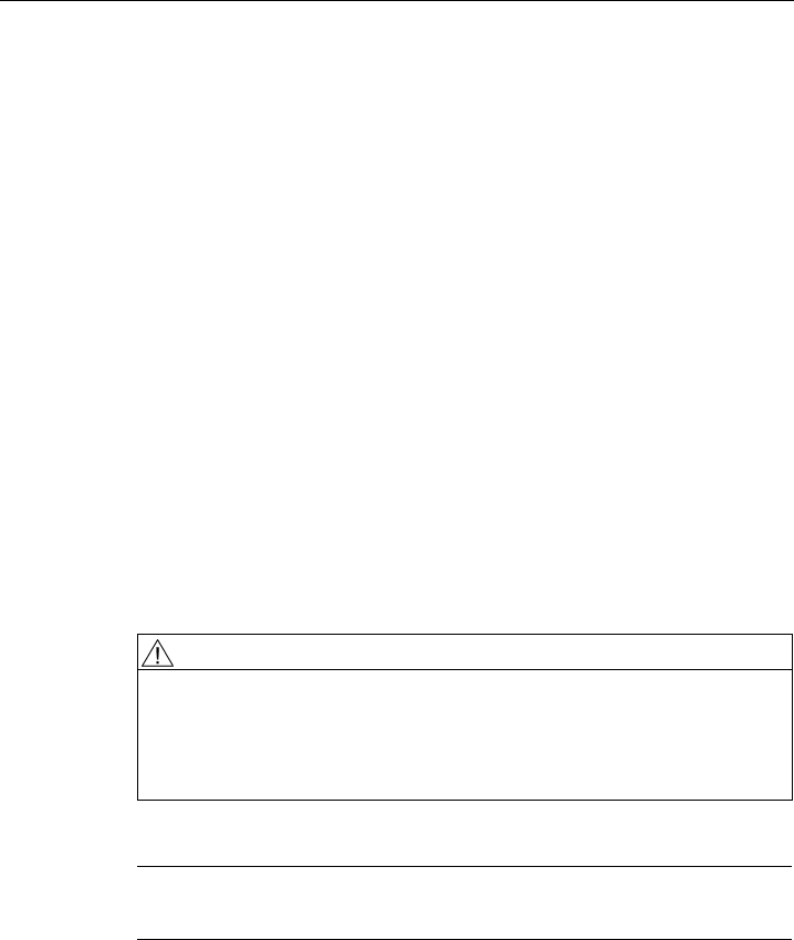
5.3 Maßzeichnung ANT795-4MR
21,2
34,6
148
13
6
SCALANCE W788-xPRO/RR / SCALANCE W74x-1PRO/RR
Betriebsanleitung (kompakt), Ausgabe 08/2007, A5E00413342-05 47
Zulassungen 6
6.1 Zulassungen SCALANCE W788-xPRO/RR und 74x-1PRO/RR
CE-Konformität
Die Produkte
SIMATIC NET SCALANCE W788-1PRO
SIMATIC NET SCALANCE W788-2PRO
SIMATIC NET SCALANCE W788-1RR
SIMATIC NET SCALANCE W788-2RR
SIMATIC NET SCALANCE W744-1PRO
SIMATIC NET SCALANCE W746-1PRO
SIMATIC NET SCALANCE W747-1RR
stimmen in der von Siemens A&D in Verkehr gebrachten Ausführung mit den Vorschriften
der folgenden europäischen Richtlinie überein:
● 99/5/EG
Richtlinie des europäischen Parlaments und des Rates zur Angleichung der
Rechtsvorschriften der Mitgliedstaaten über Funkanlagen und
Telekommunikationsendeinrichtungen und die gegenseitige Anerkennung ihrer
Konformität.
Die Konformität mit den grundlegenden Anforderungen der Richtlinie wird nachgewiesen
durch die Einhaltung folgender Normen:
● EN 60950
Sicherheit von Einrichtungen der Informationstechnik
● EN 301489-1
Elektromagnetische Verträglichkeit für Funkeinrichtungen und -dienste
● EN 301489-17
Spezifische Bedingungen für Breitband-Datenübertragungssysteme und für
Einrichtungen in lokalen Hochleistungs-Funknetzen (HIPERLAN)
● EN 300328
Elektromagnetische Verträglichkeit und Funkspektrumangelegen¬heiten
● EN 301893
Breitband-Funkzugangsnetze (BRAN) – 5 GHz-Hochleistungs-RLAN
● EN 50371
Übereinstimmung von elektronischen und elektrischen Geräten kleiner Leistung mit den
Basisgrenzwerten für die Sicherheit von Personen in elektromagnetischen Feldern (10
MHz bis 300 GHz)

Zulassungen
6.1 Zulassungen SCALANCE W788-xPRO/RR und 74x-1PRO/RR
SCALANCE W788-xPRO/RR / SCALANCE W74x-1PRO/RR
48 Betriebsanleitung (kompakt), Ausgabe 08/2007, A5E00413342-05
● 1999/519/EC
Empfehlung des Rates zur Begrenzung der Exposition der Bevölkerung gegenüber
elektromagnetischen Feldern (0 Hz — 300 GHz)
An das System angeschlossene Geräte müssen die relevanten Sicherheitsbestimmungen
erfüllen.
Die EG-Konformitätserklärung wird gemäß den obengenannten EG- Richtlinien für die
zuständigen Behörden zur Verfügung gehalten bei:
Siemens Aktiengesellschaft
Automation and Drives
Industrielle Kommunikation
Postfach 4848
D-90327 Nürnberg
Diese Erklärung bescheinigt die Übereinstimmung mit den genannten Richtlinien, ist jedoch
keine Zusicherung von Eigenschaften.
Zulassungen
6.1 Zulassungen SCALANCE W788-xPRO/RR und 74x-1PRO/RR
SCALANCE W788-xPRO/RR / SCALANCE W74x-1PRO/RR
Betriebsanleitung (kompakt), Ausgabe 08/2007, A5E00413342-05 49
Zulassungen
6.1 Zulassungen SCALANCE W788-xPRO/RR und 74x-1PRO/RR
SCALANCE W788-xPRO/RR / SCALANCE W74x-1PRO/RR
50 Betriebsanleitung (kompakt), Ausgabe 08/2007, A5E00413342-05
ATEX-, cULus- und FM-Zulassungen
Die Produkte
SIMATIC NET SCALANCE W788-1PRO
SIMATIC NET SCALANCE W788-2PRO
SIMATIC NET SCALANCE W788-1RR
SIMATIC NET SCALANCE W788-2RR
SIMATIC NET SCALANCE W744-1PRO
SIMATIC NET SCALANCE W746-1PRO
SIMATIC NET SCALANCE W747-1RR
verfügen über die Zulassungen
● EN 60079-15
II 3 G Ex nA II T..
KEMA 07 ATEX 0145X
● c-UL-us:
UL 60950-1 CSA C22.2 No. 60950-1
● c-UL-us for hazardous location*:
ISA 12.12.01-2000, CSA C22.2 No. 213-M1987
CL. 1, Div. 2 GP. A.B.C.D T..
CL. 1, Zone 2, GP, IIC, T..
CL. 1, Zone 2, AEx nC IIC T..
● FM 3611 Hazardous (Classified) Location Electrical Equipment:
Non Incendive / Class I / Division 2 / Groups A,B,C,D / T* and
Non Incendive / Class I / Zone 2 / Group IIC / T*
(T.. / T* = Konkrete Angaben zur Temperaturklasse finden Sie auf dem Typenschild)
WARNUNG
Bei Einsatz unter Ex-Schutz Bedingungen (Zone 2) muss das Produkt SCALANCE W788-
xPRO/RR bzw. W74x-1PRO/RR in ein Gehäuse eingebaut werden, welches im
Geltungsbereich der EN 50021 mindestens IP 54 nach EN 60529 besitzt.
DAS GERÄT DARF NUR DANN AN DIE SPANNUNGSVERSORGUNG
ANGESCHLOSSEN ODER VON IHR GETRENNT WERDEN, WENN EINE
EXPLOSIONSGEFAHR MIT SICHERHEIT AUSGESCHLOSSEN WERDEN KANN.
Hinweis
Die angegebenen Zulassungen gelten erst dann als erteilt, wenn auf dem Produkt eine
entsprechende Kennzeichnung angebracht ist.

Zulassungen
6.1 Zulassungen SCALANCE W788-xPRO/RR und 74x-1PRO/RR
SCALANCE W788-xPRO/RR / SCALANCE W74x-1PRO/RR
Betriebsanleitung (kompakt), Ausgabe 08/2007, A5E00413342-05 51
FCC-Zulassung
This device complies with Part 15 of the FCC Rules and with RSS-210 of Industry Canada.
Operation is subject to the following two conditions:
(1) this device may not cause harmful interference, and
(2) this device must accept any interference received, including interference that may cause
undesired operation.
_________________________________________________________________________________
Notice
Changes or modifications made to this equipment not expressly approved by SIEMENS may
void the FCC authorization to operate this equipment.
_________________________________________________________________________________
This equipment has been tested and found to comply with the limits for a Class B digital
device, pursuant to Part 15 of the FCC Rules. These limits are designed to provide
reasonable protection against harmful interference in a residential installation. This
equipment generates, uses and can radiate radio frequency energy and, if not installed and
used in accordance with the instructions, may cause harmful interference to radio
communications. However, there is no guarantee that interference will not occur in a
particular installation. If this equipment does cause harmful interference to radio or television
reception, which can be determined by turning the equipment off and on, the user is
encouraged to try to correct the interference by one or more of the following measures:
● Reorient or relocate the receiving antenna.
● Increase the separation between the equipment and receiver.
● Connect the equipment into an outlet on a circuit different from that to which the receiver
is connected.
Consult the dealer or an experienced radio/TV technician for help.
_________________________________________________________________________________
Notice
This equipment complies with FCC radiation exposure limits set forth for an uncontrolled
environment. This equipment should be installed and operated with minimum distance 20 cm
between the radiator and your body.
This transmitter must not be co-located or operating in conjunction with any other antenna or
transmitter.
_________________________________________________________________________________

Zulassungen
6.2 Länderzulassungen SCALANCE W788-xPRO/RR W74x-1PRO/RR
SCALANCE W788-xPRO/RR / SCALANCE W74x-1PRO/RR
52 Betriebsanleitung (kompakt), Ausgabe 08/2007, A5E00413342-05
6.2 Länderzulassungen SCALANCE W788-xPRO/RR W74x-1PRO/RR
Länderzulassungen
Im Folgenden finden Sie die vom Institute of Electrical and Electronics Engineers, Inc.
(IEEE) zugelassenen und von SCALANCE W788-xPRO/RR- bzw. W74x-1PRO/RR-Geräten
nutzbaren Kanäle.
Spalte Bedeutung
Land Land
Modus IEEE 802.11-Standard sowie gegebenenfalls erforderliche TPC- und / oder
DFS-Funktionalität
CH Kanal
MHz Frequenz
PWR (EIRP) Maximal zulässige mittlere äquivalente isotrope Strahlungsleistung
Verwendung Zugelassene Nutzung im Indoor- und / oder Outdoor-Betrieb
Zulassungen
6.2 Länderzulassungen SCALANCE W788-xPRO/RR W74x-1PRO/RR
SCALANCE W788-xPRO/RR / SCALANCE W74x-1PRO/RR
Betriebsanleitung (kompakt), Ausgabe 08/2007, A5E00413342-05 53
Die Produkte SCALANCE W788-xPRO/RR- bzw. W74x-1PRO/RR sind in folgenden
Ländern zugelassen:
Land Modus CH MHz PWR
(EIRP)
Verwendung
Belgien
Dänemark
Deutschland
Finnland
Griechenland
Großbritannien
Irland
Island
Italien
Liechtenstein
Luxemburg
Niederlande
Norwegen
Österreich
Polen
Portugal
Rumänien
Schweden
Schweiz
Slowakei
Slowenien
Spanien
Ungarn
11b 11g
g-Turbo
11a
TPC
11h
DFS+TPC
DFS+TPC
1
-
13
36
-
48
36
-
64
100
-
140
2412
-
2472
5180
-
5240
5180
-
5320
5500
-
5700
100 mW
60 mW
200 mW
1000 mW
Indoor + Outdoor
Indoor only
Indoor only
Indoor + Outdoor
Bulgarien 11b 11g
g-Turbo
11h
DFS+TPC
DFS+TPC
1
-
13
36
-
56
100
-
140
2412
-
2472
5180
-
5280
5500
-
5700
100 mW
200 mW
1000 mW
Indoor + Outdoor
Indoor only
Indoor + Outdoor

Zulassungen
6.2 Länderzulassungen SCALANCE W788-xPRO/RR W74x-1PRO/RR
SCALANCE W788-xPRO/RR / SCALANCE W74x-1PRO/RR
54 Betriebsanleitung (kompakt), Ausgabe 08/2007, A5E00413342-05
Land Modus CH MHz PWR
(EIRP)
Verwendung
Frankreich
11b 11g
g-Turbo
11a
TPC
11h
DFS+TPC
1
-
7
8
-
13
36
-
48
36
-
64
2412
-
2442
2447
-
2472
5180
-
5240
5180
-
5320
100 mW
100 mW
60 mW
200 mW
Indoor + Outdoor
Indoor only
Indoor only
Indoor only
Tschechische
Republik
11b 11g
g-Turbo
11a
TPC
11h
DFS+TPC
1
-
13
36
-
48
36
-
64
2412
-
2472
5180
-
5240
5180
-
5320
100 mW
60 mW
200 mW
Indoor + Outdoor
Indoor only
Indoor only

Zulassungen
6.2 Länderzulassungen SCALANCE W788-xPRO/RR W74x-1PRO/RR
SCALANCE W788-xPRO/RR / SCALANCE W74x-1PRO/RR
Betriebsanleitung (kompakt), Ausgabe 08/2007, A5E00413342-05 55
Länderzulassungen für Gerätevarianten
Für die in der folgenden Tabelle aufgeführten Geräte gelten geänderte Länderzulassungen.
Typ Bestell-Nr. Bestell-Nr. US-Variante
W788-1PRO 6GK5788-1ST00-2AA6 6GK5788-1ST00-2AB6
W788-2PRO 6GK5788-2ST00-2AA6 6GK5788-2ST00-2AB6
W788-1RR 6GK5788-1SR00-2AA6 6GK5788-1SR00-2AB6
W788-2RR 6GK5788-2SR00-2AA6 6GK5788-2SR00-2AB6
W744-1PRO 6GK5744-1ST00-2AA6 6GK5744-1ST00-2AB6
W746-1PRO 6GK5746-1ST00-2AA6 6GK5746-1ST00-2AB6
W747-1RR 6GK5747-1SR00-2AA6 6GK5747-1SR00-2AB6
Diese Geräte sind in folgenden Ländern zugelassen:
Land Modus CH MHz PWR
(EIRP)
Verwendung
Argentinien 11b
11a
TPC
TPC
1
-
13
56
-
64
149
-
161
2412
-
2472
5280
-
5320
5745
-
5805
<
100 mW
50 mW
1000 mW
Indoor + Outdoor
Indoor + Outdoor
Indoor + Outdoor
Australien
11b 11g
g-Turbo
11a
TPC
TPC
11a-Turbo
TPC
TPC
TPC
TPC
TPC
1
-
13
36
-
64
149
-
165
42
50
58
152
160
2412
-
2472
5180
5320
5745
-
5825
5210
5250
5290
5760
5800
100 mW
200 mW
1000 mW
50 mW
200 mW
200 mW
1000 mW
1000 mW
100 mW
200 mW
1000 mW
50 mW
200 mW
200 mW
1000 mW
1000 mW

Zulassungen
6.2 Länderzulassungen SCALANCE W788-xPRO/RR W74x-1PRO/RR
SCALANCE W788-xPRO/RR / SCALANCE W74x-1PRO/RR
56 Betriebsanleitung (kompakt), Ausgabe 08/2007, A5E00413342-05
Land Modus CH MHz PWR
(EIRP)
Verwendung
Belgien
11b 11g
g-Turbo
11a
TPC
11h
DFS+TPC
DFS+TPC
1
-
13
36
-
48
36
-
64
100
-
140
2412
-
2472
5180
-
5240
5180
-
5320
5500
-
5700
100 mW
60 mW
200 mW
1000 mW
Indoor only
Indoor only
Indoor only
Indoor + Outdoor
Brasilien 11b
11h
DFS+TPC
DFS+TPC
DFS+TPC
1
-
13
36
-
48
52
-
64
149
-
165
2412
-
2472
5180
-
5240
5260
-
5320
5745
-
5825
400 mW
50 mW
100 mW
1000 mW
Indoor + Outdoor
Indoor only
Indoor only
Indoor only
Bulgarien 11b 11g
g-Turbo
11h
DFS+TPC
DFS+TPC
1
-
13
36
-
56
100
-
140
2412
-
2472
5180
-
5280
5500
-
5700
100 mW
200 mW
1000 mW
Indoor + Outdoor
Indoor only
Indoor + Outdoor
Zulassungen
6.2 Länderzulassungen SCALANCE W788-xPRO/RR W74x-1PRO/RR
SCALANCE W788-xPRO/RR / SCALANCE W74x-1PRO/RR
Betriebsanleitung (kompakt), Ausgabe 08/2007, A5E00413342-05 59
Land Modus CH MHz PWR
(EIRP)
Verwendung
Hong Kong 11b 11g
g-Turbo
11a
TPC
TPC
11a-Turbo
TPC
1
-
13
36
-
64
149
-
165
42
50
58
152
160
2412
-
2472
5180
-
5320
5745
-
5825
5210
5250
5290
5760
5800
100 mW
200 mW
1000 mW
50 mW
200 mW
200 mW
1000 mW
1000 mW
Indoor + Outdoor
Indoor + Outdoor
Indoor + Outdoor
Indoor + Outdoor
Indoor + Outdoor
Indoor + Outdoor
Indoor + Outdoor
Indoor + Outdoor
Indien 11b 11g
g-Turbo
1
-
13
2412
-
2472
100 mW
Indoor only
Japan
11b 11g
11a
TPC
TPC
TPC
1
-
14
184
-
196
8
-
16
36
-
48
2412
-
2484
4920
-
4980
5040
-
5080
5180
-
5240
100 mW
200 mW
200 mW
200 mW
Indoor + Outdoor
Indoor + Outdoor
Indoor + Outdoor
Indoor only
Japan Old 11b 11g
11a
TPC
TPC
TPC
1
-
14
184
-
196
8
-
16
34
-
46
2412
-
2484
4920
-
4980
5040
-
5080
5170
-
5230
100 mW
200 mW
200 mW
200 mW
Indoor + Outdoor
Indoor + Outdoor
Indoor + Outdoor
Indoor only

Zulassungen
6.2 Länderzulassungen SCALANCE W788-xPRO/RR W74x-1PRO/RR
SCALANCE W788-xPRO/RR / SCALANCE W74x-1PRO/RR
58 Betriebsanleitung (kompakt), Ausgabe 08/2007, A5E00413342-05
Land Modus CH MHz PWR
(EIRP)
Verwendung
Dänemark
Deutschland
Finnland
Griechenland
Großbritannien
Irland
Island
Italien
Liechtenstein
Luxemburg
Niederlande
Norwegen
Österreich
Polen
Portugal
Schweden
Schweiz
Slowakei
Slowenien
Spanien
Ungarn
11b 11g
g-Turbo
11a
TPC
11h
DFS+TPC
DFS+TPC
1
-
13
36
-
48
36
-
64
100
-
140
2412
-
2472
5180
-
5240
5180
-
5320
5500
-
5700
100 mW
60 mW
200 mW
1000 mW
Indoor + Outdoor
Indoor only
Indoor only
Indoor + Outdoor
Frankreich
11b 11g
g-Turbo
11a
TPC
11h
DFS+TPC
1
-
7
8
-
13
36
-
48
36
-
64
100
-
140
2412
-
2442
2447
-
2472
5180
-
5240
5180
-
5320
5500
-
5700
100 mW
100 mW
60 mW
200 mW
1000 mW
Indoor + Outdoor
Indoor only
Indoor only
Indoor only
Indoor + Outdoor
Zulassungen
6.2 Länderzulassungen SCALANCE W788-xPRO/RR W74x-1PRO/RR
SCALANCE W788-xPRO/RR / SCALANCE W74x-1PRO/RR
Betriebsanleitung (kompakt), Ausgabe 08/2007, A5E00413342-05 59
Land Modus CH MHz PWR
(EIRP)
Verwendung
Hong Kong 11b 11g
g-Turbo
11a
TPC
TPC
11a-Turbo
TPC
1
-
13
36
-
64
149
-
165
42
50
58
152
160
2412
-
2472
5180
-
5320
5745
-
5825
5210
5250
5290
5760
5800
100 mW
200 mW
1000 mW
50 mW
200 mW
200 mW
1000 mW
1000 mW
Indoor + Outdoor
Indoor + Outdoor
Indoor + Outdoor
Indoor + Outdoor
Indoor + Outdoor
Indoor + Outdoor
Indoor + Outdoor
Indoor + Outdoor
Indien 11b 11g
g-Turbo
1
-
13
2412
-
2472
100 mW
Indoor only
Japan
11b 11g
11a
TPC
TPC
TPC
1
-
14
184
-
196
8
-
16
36
-
48
2412
-
2484
4920
-
4980
5040
-
5080
5180
-
5240
100 mW
200 mW
200 mW
200 mW
Indoor + Outdoor
Indoor + Outdoor
Indoor + Outdoor
Indoor only

Zulassungen
6.2 Länderzulassungen SCALANCE W788-xPRO/RR W74x-1PRO/RR
SCALANCE W788-xPRO/RR / SCALANCE W74x-1PRO/RR
60 Betriebsanleitung (kompakt), Ausgabe 08/2007, A5E00413342-05
Land Modus CH MHz PWR
(EIRP)
Verwendung
Japan Old 11b 11g
11a
TPC
TPC
TPC
1
-
14
184
-
196
8
-
16
34
-
46
2412
-
2484
4920
-
4980
5040
-
5080
5170
-
5230
100 mW
200 mW
200 mW
200 mW
Indoor + Outdoor
Indoor + Outdoor
Indoor + Outdoor
Indoor only
Kanada 11b 11g
g-Turbo
11a
TPC
TPC
11a-Turbo
TPC
TPC
TPC
TPC
TPC
1
-
11
36
-
48
149
-
161
42
50
58
152
160
2412
-
2462
5180
-
5240
5745
-
5805
5210
5250
5290
5760
5800
500 mW
100 mW
1000 mW
50 mW
200 mW
200 mW
1000 mW
1000 mW
Indoor + Outdoor
Indoor only
Indoor only
Indoor only
Indoor + Outdoor
Indoor + Outdoor
Indoor + Outdoor
Indoor + Outdoor
Korea
11b 11g
1
-
13
2412
-
2472
100 mW
Indoor + Outdoor
Kuwait 11b 11g
g-Turbo 1
-
13
2412
-
2472
100 mW
Indoor + Outdoor

Zulassungen
6.2 Länderzulassungen SCALANCE W788-xPRO/RR W74x-1PRO/RR
SCALANCE W788-xPRO/RR / SCALANCE W74x-1PRO/RR
Betriebsanleitung (kompakt), Ausgabe 08/2007, A5E00413342-05 61
Land Modus CH MHz PWR
(EIRP)
Verwendung
Malaysia 11b 11g
11a
TPC
TPC
1
-
13
56
-
64
149
-
165
2412
-
2472
5280
-
5320
5745
-
5825
100 mW
200 mW
1000 mW
Indoor + Outdoor
Indoor only
Indoor + Outdoor
Russland 11b 11g
g-Turbo 1
-
13
2412
-
2472
100 mW
Indoor + Outdoor
Singapur 11b 11g
g-Turbo
11h
DFS+TPC
DFS+TPC
11h-Turbo
DFS+TPC
1
-
13
36
-
64
149
-
165
42
50
58
152
160
2412
-
2472
5180
-
5320
5745
-
5825
5210
5250
5290
5760
5800
100 mW
100 mW
100 mW
100 mW
Indoor + Outdoor
Indoor + Outdoor
Indoor + Outdoor
Indoor + Outdoor
Südafrika 11b 11g
g-Turbo
11a
TPC
11h
DFS+TPC
DFS+TPC
1
-
13
36
-
48
36
-
64
100
-
140
2412
-
2472
5180
-
5240
5180
-
5320
5500
-
5700
100 mW
60 mW
200 mW
1000 mW
Indoor + Outdoor
Indoor + Outdoor
Indoor only
Indoor + Outdoor
Zulassungen
6.2 Länderzulassungen SCALANCE W788-xPRO/RR W74x-1PRO/RR
SCALANCE W788-xPRO/RR / SCALANCE W74x-1PRO/RR
62 Betriebsanleitung (kompakt), Ausgabe 08/2007, A5E00413342-05
Land Modus CH MHz PWR
(EIRP)
Verwendung
Tschechische
Republik
11b 11g
g-Turbo
11a
TPC
11h
DFS+TPC
1
-
13
36
-
48
36
-
64
2412
-
2472
5180
-
5240
5180
-
5320
100 mW
60 mW
200 mW
Indoor + Outdoor
Indoor only
Indoor only
Türkei 11b 11g
g-Turbo
11a
TPC
11h
DFS+TPC
1
-
13
36
-
48
36
-
64
2412
-
2472
5180
-
5240
5180
-
5320
100 mW
60 mW
200 mW
Indoor + Outdoor
Indoor only
Indoor only
Vereinigte
Arabische Emirate
11b 11g
g-Turbo
1
-
13
2412
-
2472
100 mW Indoor + Outdoor
Vereinigte Staaten
von Amerika
11b 11g
g-Turbo
11a
TPC
TPC
11a-Turbo
TPC
TPC
1
-
11
36
-
48
149
-
165
152
160
2412
-
2462
5180
-
5240
5745
-
5825
-
5760
5800
500 mW
50 mW
1000 mW
1000 mW
1000 mW
Indoor + Outdoor
Indoor only
Indoor + Outdoor
Indoor + Outdoor
Indoor + Outdoor

Zulassungen
6.2 Länderzulassungen SCALANCE W788-xPRO/RR W74x-1PRO/RR
SCALANCE W788-xPRO/RR / SCALANCE W74x-1PRO/RR
Betriebsanleitung (kompakt), Ausgabe 08/2007, A5E00413342-05 63
Hinweis
Dieser Hinweis und die folgende Tabelle gilt nur für Japan.
• Die in der folgenden Liste aufgeführten Antennen werden mit den angegebenen
vorkonfektionierten Kabellängen ausgeliefert.
• Die angegebenen Kabellängen dürfen nicht unterschritten werden.
Antenne Frequenz (MHz) EIRP (dBm/MHz) Zulassungseinschränkungen
(Notwendige Kabeldämpfung)
ANT795-4MR 2400-2483,5
2471-2497
5150-5250
4900-5000
5030-5091
≤ 12,14 dBm/MHz keine
ANT795-6MR 2400-2483,5
2471-2497
≤ 12,14 dBm/MHz 3,9 dB/5m
(0,78 dB/m)
ANT795-6MR 5150-5250 ≤ 10 dBm/MHz 3,7 dB/5m
(0,74 dB/m)
ANT795-6MR 4900-5000
5030-5091
≤ 10 dBm/MHz 3,7 dB/5m
(0,74 dB/m)
ANT792-8DR 2400-2483,5
2471-2497
≤ 22,14 dBm/MHz keine
ANT793-8DR 5150-5250 ≤ 10 dBm/MHz 14,4 dB/12m
(1,2 dB/m)
ANT793-8DR 4900-5000
5030-5091
≤ 20 dBm/MHz 6 dB/5m
(0,83 dB/m)
ANT792-4DN 2400-2483,5
2471-2497
≤ 12,14 dBm/MHz keine

Zulassungen
6.2 Länderzulassungen SCALANCE W788-xPRO/RR W74x-1PRO/RR
SCALANCE W788-xPRO/RR / SCALANCE W74x-1PRO/RR
64 Betriebsanleitung (kompakt), Ausgabe 08/2007, A5E00413342-05

Introduction
1
Description
2
Mounting
3
Connecting up
4
Technical specifications
5
Certification
6
SCALANCE W788-xPRO/RR /
SCALANCE W74x-1PRO/RR
Operating Instructions (Compact)
Release 08/2007
A5E00413342-05
Safety Guidelines
This manual contains notices you have to observe in order to ensure your personal safety, as well as to prevent
damage to property. The notices referring to your personal safety are highlighted in the manual by a safety alert
symbol, notices referring only to property damage have no safety alert symbol. These notices shown below are
graded according to the degree of danger.
DANGER
indicates that death or severe personal injury will result if proper precautions are not taken.
WARNING
indicates that death or severe personal injury may result if proper precautions are not taken.
CAUTION
with a safety alert symbol, indicates that minor personal injury can result if proper precautions are not taken.
CAUTION
without a safety alert symbol, indicates that property damage can result if proper precautions are not taken.
NOTICE
indicates that an unintended result or situation can occur if the corresponding information is not taken into
account.
If more than one degree of danger is present, the warning notice representing the highest degree of danger will
be used. A notice warning of injury to persons with a safety alert symbol may also include a warning relating to
property damage.
Qualified Personnel
The device/system may only be set up and used in conjunction with this documentation. Commissioning and
operation of a device/system may only be performed by qualified personnel. Within the context of the safety notes
in this documentation qualified persons are defined as persons who are authorized to commission, ground and
label devices, systems and circuits in accordance with established safety practices and standards.
Prescribed Usage
Note the following:
WARNING
This device may only be used for the applications described in the catalog or the technical description and only
in connection with devices or components from other manufacturers which have been approved or
recommended by Siemens. Correct, reliable operation of the product requires proper transport, storage,
positioning and assembly as well as careful operation and maintenance.
Trademarks
All names identified by ® are registered trademarks of the Siemens AG. The remaining trademarks in this
publication may be trademarks whose use by third parties for their own purposes could violate the rights of the
owner.
Disclaimer of Liability
We have reviewed the contents of this publication to ensure consistency with the hardware and software
described. Since variance cannot be precluded entirely, we cannot guarantee full consistency. However, the
information in this publication is reviewed regularly and any necessary corrections are included in subsequent
editions.
Siemens AG
Automation and Drives
Postfach 48 48
90327 NÜRNBERG
GERMANY
Ordernumber: A5E00413342-05
Ⓟ 08/2007
Copyright © Siemens AG 2007.
Technical data subject to change
SCALANCE W788-xPRO/RR / SCALANCE W74x-1PRO/RR
Operating Instructions (Compact), Release 08/2007, A5E00413342-05 67
Table of contents
1 Introduction ............................................................................................................................................. 69
1.1 Information on the Operating Instructions (compact) SCALANCE W788-xPRO/RR and
W74x-1PRO/RR .......................................................................................................................... 69
1.2 Type designations........................................................................................................................ 70
2 Description.............................................................................................................................................. 73
2.1 Components of the product ......................................................................................................... 73
2.2 Product properties ....................................................................................................................... 74
2.3 Different properties for devices with other hardware................................................................... 77
2.4 LED displays................................................................................................................................ 82
2.5 C-PLUG ....................................................................................................................................... 85
2.6 Reset button................................................................................................................................. 85
2.7 Biological compatibility................................................................................................................. 86
3 Mounting................................................................................................................................................. 87
3.1 Securing the housing................................................................................................................... 87
3.2 Drilling template for the SCALANCE W788-xPRO/RR and SCALANCE W74x-1PRO/RR ........ 88
4 Connecting up......................................................................................................................................... 89
4.1 Cabling for power supply and Ethernet ....................................................................................... 89
4.2 Lightning protection, power supply, and grounding..................................................................... 90
4.3 Suitable antenna cables and antennas for SCALANCE W-700.................................................. 92
4.4 Connectors for external antennas and power supply.................................................................. 94
4.5 Assembling an IE hybrid cable 2 x 2 + 4 x 0.34 with an IE IP 67 hybrid connector.................... 96
4.6 Fitting the IE FC TP standard cable 4 x 2 GP to an IE IP 67 hybrid connector ........................ 100
4.7 Pinning of the M12 male connector........................................................................................... 104
5 Technical specifications .........................................................................................................................105
5.1 Technical specifications for the SCALANCE W788-xPRO/RR and W74x-1PRO/RR .............. 105
5.2 Technical specifications ANT795-4MR ..................................................................................... 107
5.3 Dimension drawing ANT795-4MR............................................................................................. 108
6 Certification............................................................................................................................................109
6.1 Approvals for the SCALANCE W788-xPRO/RR and 74x-1PRO/RR........................................ 109
6.2 National approvals for the SCALANCE W788-xPRO/RR / W74x-1PRO/RR............................ 114

SCALANCE W788-xPRO/RR / SCALANCE W74x-1PRO/RR
Operating Instructions (Compact), Release 08/2007, A5E00413342-05 69
Introduction 1
1.1 Information on the Operating Instructions (compact) SCALANCE
W788-xPRO/RR and W74x-1PRO/RR
Validity of the Operating Instructions (compact)
These Operating Instructions (compact) cover the following products:
● SCALANCE W788-1PRO
● SCALANCE W788-2PRO
● SCALANCE W788-1RR
● SCALANCE W788-2RR
● SCALANCE W744-1PRO
● SCALANCE W746-1PRO
● SCALANCE W747-1RR
These Operating Instructions (compact) apply to the following software version:
● SCALANCE W788-xPRO/RR or W74x-1PRO/RR with firmware as of version 3.3
Purpose of the Operating Instructions (compact)
Based on the Operating Instructions (compact), you will be able to install and connect up the
SCALANCE W788-xPRO/RR or W74x-1PRO/RR correctly. The configuration and the
integration of the device in a WLAN are not described in these instructions.
Documentation on the accompanying CD
You will find the operating instructions for the products listed above on the accompanying
CD, file name
BA_SCALANCE-W788-xPRORR-W74x-1PRORR_76.pdf
NOTICE
Make sure that you read the explanations and instructions in the README.txt file

Introduction
1.2 Type designations
SCALANCE W788-xPRO/RR / SCALANCE W74x-1PRO/RR
70 Operating Instructions (Compact), Release 08/2007, A5E00413342-05
1.2 Type designations
Abbreviations used
The information in the manuals for the SCALANCE W-700 product family often applies to
more than one product variant. In such situations, the designations of the products are
shortened to avoid having to list all the type designations. The following table shows how the
abbreviations relate to the product variants.
Product group The designation . . . stands
for . . .
Product name
Ethernet client modules (IP30, cabinet
installation)
W74x-1 W744-1
W746-1
W747-1
Ethernet client modules (IP65, installed
outside a cabinet)
W74x-1PRO/RR W744-1PRO
W746-1PRO
W747-1RR
All Ethernet client modules
SCALANCE W
W74x W744-1
W746-1
W747-1
W744-1PRO
W746-1PRO
W747-1RR
Access points (IP30, cabinet installation) W784-1xx W784-1
W784-1RR
Access points (IP65, installed outside a
cabinet, extreme climatic requirements)
W786-xPRO W786-1PRO
W786-2PRO
W786-3PRO
Access points (IP65, installed outside a
cabinet)
W788-xPRO/RR W788-1PRO
W788-2PRO
W788-1RR
W788-2RR
Access points with the "RR" range of
functions
W-78x-xRR W784-1RR
W788-1RR
W788-2RR
All SCALANCE W access points W78x W788-1PRO
W788-2PRO
W788-1RR
W788-2RR
W786-1PRO
W786-2PRO
W786-3PRO
W784-1
W784-1RR

Introduction
1.2 Type designations
SCALANCE W788-xPRO/RR / SCALANCE W74x-1PRO/RR
Operating Instructions (Compact), Release 08/2007, A5E00413342-05 71
Product group The designation . . . stands
for . . .
Product name
All SCALANCE W devices W -700 W788-1PRO
W788-2PRO
W788-1RR
W788-2RR
W744-1PRO
W746-1PRO
W747-1RR
W786-1PRO
W786-2PRO
W786-3PRO
W784-1
W784-1RR
W744-1
W746-1
W747-1
SCALANCE W788-xPRO/RR / SCALANCE W74x-1PRO/RR
Operating Instructions (Compact), Release 08/2007, A5E00413342-05 73
Description 2
2.1 Components of the product
The following parts belong to the consignment of the SCALANCE W788-xPRO/RR or W74x-
1PRO/RR:
● SCALANCE W788-xPRO/RR or W74x-1PRO/RR
● 2 OMNI antennas ANT795-4MR
● 1 IE IP 67 hybrid plug-in connector
● 1 protective cap for the M12 socket
● 2 (or 4 with SCALANCE W788-2PRO or SCALANCE W788-2RR) sealing plugs for the R-
SMA sockets
● 1 SIMATIC NET Industrial Wireless LAN CD with the Operating Instructions for the
SCALANCE W788-xPRO/RR and W74x-1PRO/RR
Please check that the consignment you have received is complete. If it is not complete,
please contact your supplier or your local Siemens office.

Description
2.2 Product properties
SCALANCE W788-xPRO/RR / SCALANCE W74x-1PRO/RR
74 Operating Instructions (Compact), Release 08/2007, A5E00413342-05
2.2 Product properties
Note
The SIMATIC NET WLAN products use OpenSSL.
This involves "Open Source Code" with license conditions (BSD).
Please note and adhere to the current license conditions.
Since the driver includes encryption software, you should also adhere to the appropriate
regulations for your specific country.
Potential uses of the SCALANCE W788-xPRO / W788-xRR
The SCALANCE W788-xPRO / W788-xRR is equipped with an Ethernet port and one or two
wireless LAN ports. This makes the device suitable for the following applications:
● The SCALANCE W788-xPRO / W788-xRR forwards data within its transmission range
from one node to another without a connection to wired Ethernet being necessary.
● The SCALANCE W788-xPRO / W788-xRR can be used as a gateway from a wired to a
wireless network.
● The SCALANCE W788-xPRO / W788-xRR can be used as a wireless bridge between
two networks.
● The SCALANCE W788-xPRO / W788-xRR can be used as a bridge between two
different frequencies.
Possible applications of the SCALANCE W744-1PRO
The SCALANCE W744-1PRO is equipped with an Ethernet port and a wireless LAN port.
This makes the device suitable for the following applications:
● The SCALANCE W744-1PRO is used to connect a device with an Ethernet port (for
example, a SIMATIC PLC with Industrial Ethernet communications processor) to a
WLAN.
● The SCALANCE W744-1PRO can be used as a gateway from a wired to a wireless
network. One node in the wired network is supported.
Possible applications of the SCALANCE W746-1PRO
The SCALANCE W746-1PRO provides the same functionality as the SCALANCE W744-
1PRO. The device can also connect up to 8 stations with IP communication on the Ethernet
port to a wireless cell.

Description
2.2 Product properties
SCALANCE W788-xPRO/RR / SCALANCE W74x-1PRO/RR
Operating Instructions (Compact), Release 08/2007, A5E00413342-05 75
Possible applications of the SCALANCE W747-1RR
The SCALANCE W747-1RR provides the same functionality as the SCALANCE W746-
1PRO. The device is also capable of optimized data transfer and handover times in iPCF
mode.
Note
For PNIO communication, we always recommend that you enable the iPCF mode.
Properties of the SCALANCE W788-xx / W74x-1xx
● The Ethernet interface supports 10 Mbps and 100 Mbps, both in full and half duplex as
well as autocrossing and autopolarity.
● Operating the wireless interface in the frequency bands 2.4 GHz and 5 GHz.
● The wireless interface is compatible with the standards IEEE 802.11a,
IEEE 802.11b, and IEEE 802.11g. In the 802.11a- and 802.11g mode, the gross
transmission rate is up to 54 Mbps. In turbo mode, the transmission rate is up to 108
Mbps (not permitted in all countries and modes).
Note
If the SCALANCE W788-xPRO / W788-xRR is operated in turbo mode (A, G or H turbo),
remember that the channels adjacent to the set transmission channel are also used for
communication. Disturbances can therefore occur on these channels when there are
neighboring wireless systems. The data throughput can also be reduced if there is
competition for use of these channels.
● As an expansion of the 802.11a mode, it is also possible to operated according to the
IEEE 802.11h standard. In 802.11h mode, the procedures "Transmit Power Control"
(TPC) and "Dynamic Frequency Selection" (DFS) are used in the range 5.25 - 5.35 and
5.47 - 5.75 GHz. In some countries, this allows the frequency subband of 5.47 -
5.725 GHz to be used outdoors even with a higher transmit power.
TPC is a technique of controlling the transmit power and can reduce it to the strength
actually required. With dynamic frequency selection (DFS), the access point searches for
primary users (for example radar) on a randomly selected channel before starting
communication. If signals are found on the channel, this channel is disabled for 30
minutes and the availability check is repeated on another channel.
The gross transmission rate is up to 54 Mbps in 802.11h mode.
● Support of the authentication standards WPA, WPA-PSK, WPA2, WPA2-PSK and
IEEE 802.1x and the encryption methods WEP, AES and TKIP.
● Suitable for inclusion of a RADIUS server for authentication.
● Device-related and application-related monitoring of the wireless connection.
● The interoperability of the devices with Wi-Fi devices of other vendors was tested
thoroughly.

Description
2.2 Product properties
SCALANCE W788-xPRO/RR / SCALANCE W74x-1PRO/RR
76 Operating Instructions (Compact), Release 08/2007, A5E00413342-05
Note
All SCALANCE W-700 access points can be reconfigured for client mode.
Note
For PNIO communication, we always recommend that you enable the iPCF mode.
The following table shows the characteristics of the various model variants of the
SCALANCE W788-xPRO/RR or W74x-1PRO/RR
Type Number of
WLAN ports
Number of
supported IP nodes
(3)
Number of
supported MAC
nodes (3)
iPCF mode (1) Order No.
W788-1PRO 1 several several No 6GK5788-1AA60-2AA0
6GK5788-1AA60-2AB0 (2)
W788-2PRO 2 several several No 6GK5788-2AA60-2AA0
6GK5788-2AA60-2AB0 (2)
W788-1RR 1 several several Yes 6GK5788-1AA60-6AA0
6GK5788-1AA60-6AB0 (2)
W788-2RR 2 several several Yes 6GK5788-2AA60-6AA0
6GK5788-2AA60-6AB0 (2)
W744-1PRO 1 1 1 No 6GK5744-1AA60-2AA0
6GK5744-1AA60-2AB0 (2)
W746-1PRO 1 several several No 6GK5746-1AA60-4AA0
6GK5746-1AA60-4AB0 (2)
W747-1RR 1 several several Yes 6GK5747-1AA60-6AA0
6GK5747-1AA60-6AB0 (2)
(1) The iPCF mode provides an optimized data throughput and minimum handover times.
(2) US variant
(3) In client mode.
Requirements for installation and operation
To configure the SCALANCE W788-xPRO/RR or W74x-1PRO/RR, you require a PG/PC
connected to a network. If no DHCP server is available, a PC on which the Primary Setup
Tool (PST) is installed is necessary for the initial assignment of an IP address to the
SCALANCE W788-xPRO/RR or W74x-1PRO/RR. For the other configuration settings, a
computer with Telnet or an Internet browser is necessary.

Description
2.3 Different properties for devices with other hardware
SCALANCE W788-xPRO/RR / SCALANCE W74x-1PRO/RR
Operating Instructions (Compact), Release 08/2007, A5E00413342-05 77
2.3 Different properties for devices with other hardware
Which devices have different properties?
The information in this section applies to devices with the following order numbers:
Type Order No. Order no. US variant
W788-1PRO 6GK5788-1ST00-2AA6 6GK5788-1ST00-2AB6
W788-2PRO 6GK5788-2ST00-2AA6 6GK5788-2ST00-2AB6
W788-1RR 6GK5788-1SR00-2AA6 6GK5788-1SR00-2AB6
W788-2RR 6GK5788-2SR00-2AA6 6GK5788-2SR00-2AB6
W744-1PRO 6GK5744-1ST00-2AA6 6GK5744-1ST00-2AB6
W746-1PRO 6GK5746-1ST00-2AA6 6GK5746-1ST00-2AB6
W747-1RR 6GK5747-1SR00-2AA6 6GK5747-1SR00-2AB6
Power over Ethernet
In compliance with IEEE802.3af, the power supply is electrically isolated from the housing.
The insulation resistance is greater than 2 Mohms, the insulation voltage must not exceed
1500 V.
Multiple SSID
You can only assign an SSID to virtual access points with the types W788-1RR and W788-
2RR. Multiple SSID operation is therefore only possible with these two devices.
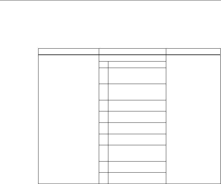
Description
2.3 Different properties for devices with other hardware
SCALANCE W788-xPRO/RR / SCALANCE W74x-1PRO/RR
78 Operating Instructions (Compact), Release 08/2007, A5E00413342-05
Antennas
The following antennas are approved for use with the SCALANCE devices listed above. You
can select an antenna in Web Based Management or in the Command Line Interface.
CLI menu: CLI\INTERFACES\WLAN1\ADVANCED> (or \WLAN2\ADVANCED)
Command Description Comment
Specify an antenna type.
0 User-defined
1 ANT795-4MR (default
antenna) - gain: 3 dBi (2.4
GHz) 5 dBi (5 GHz)
2 ANT795-6MR (incl. 5 m cable)
- gain: 3 dBi (2.4 GHz) 4 dBi (5
GHz)
3 ANT792-8DR with 5 m cable -
gain: 10 dBi (2.4 GHz)
4 ANT792-8DR with 10 m cable
- gain: 6 dBi (2.4 GHz)
5 ANT792-8DR with 15 m cable
- gain: 3 dBi (2.4 GHz)
6 ANT793-8DR with 5 m cable -
gain: 14 dBi (5 GHz)
7 ANT792-4DN (RCoax
antenna) - gain: 4 dBi (2.4
GHz)
8 ANT793-4MN (RCoax
antenna) - gain: 6 dBi (5 GHz)
anttype [0...n]
9 RCoax cable - gain: 0 dBi (2.4
GHz) 0 dBi (5 GHz)
To display the list, enter
"anttype ?".
Compatibility
You can also use configuration data of one of the devices listed above for a SCALANCE
W788-xPRO/RR or W74x-1PRO/RR with a different order number from that shown in the
table above.
Admin password for the USA variant
The default password is also "admin" for the USA variant if you have selected "admin" as the
user name.

Description
2.3 Different properties for devices with other hardware
SCALANCE W788-xPRO/RR / SCALANCE W74x-1PRO/RR
Operating Instructions (Compact), Release 08/2007, A5E00413342-05 79
Assignment of the power wires with a hybrid cable 2 x 2 + 4 x 0.34
Wire color code (standard) Brown Brown Black Black
Function 24 V 24 V Ground Ground
Power supply insert module 1 2 3 4
Assignment of the power wires with an IE FC TP standard cable 4 x 2 GP
Wire color code (standard) White / blue (1) Blue White / brown (1) Brown
Function 24 V 24 V Ground Ground
Power supply insert module 1 2 3 4
(1) White wire of the pair
Earthing
CAUTION
Damage to the device due to potential differences
There must be no potential difference between the following parts otherwise there is a risk
that the device will be destroyed:
• Ground potential of the power supply and ground potential of the antenna ground.
• Ground potential of the power supply and a grounded housing.
• Ground potential of the power supply and the ground potential of the device connected
to Industrial Ethernet (for example PC, AS-300, AS-400 etc.).
Connect both grounds to the same foundation earth or use an equipotential bonding cable.

Description
2.3 Different properties for devices with other hardware
SCALANCE W788-xPRO/RR / SCALANCE W74x-1PRO/RR
80 Operating Instructions (Compact), Release 08/2007, A5E00413342-05
Transmit power
Table 2-1 Transmit power in IEEE 802.11b mode (2.4 GHz)
Data rate [Mbps] P0 [dBm]
1 18
2 18
5,5 18
11 18
Table 2-2 Transmit power in IEEE 802.11g mode (2.4 GHz)
Data rate [Mbps] P0 [dBm]
6 17
9 17
12 17
18 17
24 17
36 13
48 11
54 10
Table 2-3 Transmit power in IEEE 802.11a/h mode (5 GHz)
Data rate [Mbps] P0 [dBm]
6 17
9 17
12 17
18 17
24 17
36 13
48 11
54 10

Description
2.3 Different properties for devices with other hardware
SCALANCE W788-xPRO/RR / SCALANCE W74x-1PRO/RR
Operating Instructions (Compact), Release 08/2007, A5E00413342-05 81
Receiver sensitivity
Table 2-4 Receiver sensitivity in IEEE 802.11b mode (2.4 GHz)
Data rate [Mbps] Pe [dBm]
1 -90
2 -90
5,5 -90
11 -84
Table 2-5 Receiver sensitivity in IEEE 802.11g mode (2.4 GHz)
Data rate [Mbps] Pe [dBm]
6 -87
9 -86
12 -85
18 -83
24 -80
36 -76
48 -71
54 -66
Table 2-6 Receiver sensitivity in IEEE 802.11a/h mode (5 GHz)
Data rate [Mbps] Pe [dBm]
6 -87
9 -86
12 -85
18 -83
24 -80
36 -76
48 -71
54 -66
72 [*] -73
96 [*] -68
108 [*] -63
[*] Turbo mode
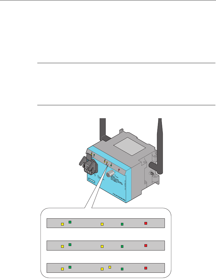
Description
2.4 LED displays
SCALANCE W788-xPRO/RR / SCALANCE W74x-1PRO/RR
82 Operating Instructions (Compact), Release 08/2007, A5E00413342-05
2.4 LED displays
Information on the operating status and data transfer of the SCALANCE W-788-xPRO/RR or W74x-
1PRO/RR
There are several LEDs on the front of the SCALANCE W788-xPRO/RR or W74x-1PRO/RR
that provide information its operating status:
Note
If the LED for the WLAN port is not green when the device starts up, although it is activated,
the port is not ready for operation (interface not initialized).
The main reason for this is usually that during commissioning of a SCALANCE W788-
xPRO/RR or W74x-1PRO/RR products, a waiting time of up to 15 minutes can occur when
the ambient temperature is below zero. The device is ready for operation at the specified
ambient temperature as soon as the LED for the WLAN interface is lit green.
P1
L2
R1
R2
L1
F
P1
L2
R1
L1
F
P1
L2
R1
L1
F
SCALANCE W788-1xx
SCALANCE W74x-1xx
SCALANCE W788-2xx
Figure 2-1 LEDs of the SCALANCE W788-xPRO/RR or W74x-1PRO/RR

Description
2.4 LED displays
SCALANCE W788-xPRO/RR / SCALANCE W74x-1PRO/RR
Operating Instructions (Compact), Release 08/2007, A5E00413342-05 83
LED Color Meaning
Yellow Data transfer over the Ethernet interface (traffic).
Green There is a connection over the Ethernet port. (Link)
Flashing yellow PRESET-PLUG detected.
Yellow/green PRESET function completed successfully.
P1
Flashing green "Flashing" enabled over PST.
L2 Green Power supply over the hybrid connector X1 (PoE or
energy contacts).
Yellow Data transfer over the first WLAN interface.
Green
W788-xPRO/RR in access point mode:
The WLAN interface is initialized and ready for operation.
W788-xPRO/RR in client mode or W74x-1PRO/RR:
There is a connection over the first WLAN interface.
Flashing green
W788-xPRO/RR in access point mode:
The channels are being scanned.
W788-xPRO/RR in client mode or W74x-1PRO/RR:
The client is searching for a connection to an access point or ad hoc
network.
Green flashing
quickly
W788-xPRO/RR in access point mode:
With 802.11h, the channel is scanned for one minute for primary users
before the channel can be used for data traffic.
W788-xPRO/RR in client mode or W74x-1PRO/RR:
The client waits for the adopt MAC address due to the setting <Auto Find
Adopt MAC> and is connected to no access point.
Green 3 x fast ,1
x long flashing
W788-xPRO/RR in client mode or W74x-1PRO/RR:
The client waits for the adopt MAC address due to the setting <Auto Find
Adopt MAC> and is connected to an access point.
Flashing yellow PRESET-PLUG detected.
R1
Yellow/green PRESET function completed successfully.
Yellow
W788-xPRO/RR in access point mode:
Data transfer over the second WLAN port.
W788-xPRO/RR in client mode or W74x-1PRO/RR:
The LED is always off because the 2nd interface is not available in client
mode.
Green
W788-xPRO/RR in access point mode:
The WLAN interface is initialized and ready for operation.
W788-xPRO/RR in client mode or W74x-1PRO/RR:
The LED is always off because the 2nd interface is not available in client
mode.
R2
Flashing green
W788-xPRO/RR in access point mode:
The channels are being scanned.
W788-xPRO/RR in client mode or W74x-1PRO/RR:
The LED is always off because the 2nd interface is not available in client
mode.

Description
2.4 LED displays
SCALANCE W788-xPRO/RR / SCALANCE W74x-1PRO/RR
84 Operating Instructions (Compact), Release 08/2007, A5E00413342-05
LED Color Meaning
Green flashing
quickly
W788-xPRO/RR in access point mode:
With 802.11h, the channel is scanned for one minute for primary users
before the channel can be used for data traffic.
W788-xPRO/RR in client mode or W74x-1PRO/RR:
The LED is always off because the 2nd interface is not available in client
mode.
Flashing yellow PRESET-PLUG detected.
Yellow/green PRESET function completed successfully.
L1 Green Power supply over the M12 connector (X2).
F Red An error has occurred during operation of the SCALANCE W788-
xPRO/RR or W74x-1PRO/RR.

Description
2.5 C-PLUG
SCALANCE W788-xPRO/RR / SCALANCE W74x-1PRO/RR
Operating Instructions (Compact), Release 08/2007, A5E00413342-05 85
2.5 C-PLUG
Configuration information on the C-PLUG
The C-PLUG is used to transfer the configuration of the old device to the new device when a
device is replaced. When the new device starts up with the C-PLUG, it then continues
automatically with exactly the same configuration as the old device. One exception to this
can be the IP configuration if it is set over DHCP and the DHCP server has not been
reconfigured accordingly.
Reconfiguration is necessary if you use WDS or redundancy with devices with more than
one WLAN interface and use the MAC addresses and not the sysNames. These functions
are then based on the MAC address that inevitably changes if a device is replaced.
Note
In terms of the C-PLUG, the SCALANCE W-700 devices work in two modes:
• Without C-PLUG
The device stores the configuration in internal memory. This mode is active when no C-
PLUG is inserted.
• With C-PLUG
The configuration stored on the C-PLUG is displayed over the user interfaces. In this
mode, the internal memory is neither read nor written. If changes are made to the
configuration, the device stores the configuration directly on the C-PLUG. This mode is
active when no C-PLUG is inserted. As soon as the device is started with a C-PLUG
inserted, the SCALANCE W-700 starts up with the configuration data on the C-PLUG.
2.6 Reset button
Functions of the reset button
The reset button is on the rear of the device below the sealing screw directly beside the C-
PLUG and has several functions:
● Restart of the device
To restart the device, press the Reset button.
● Loading new firmware
If the normal procedure with the Load & Save menu of Web Based Management does not
work, the reset button can be used to load new firmware. This situation can occur if there
was a power outage during the normal firmware update.
● Restoring the default parameters (factory defaults)
● Adopting the configuration data from the PRESET PLUG.

Description
2.7 Biological compatibility
SCALANCE W788-xPRO/RR / SCALANCE W74x-1PRO/RR
86 Operating Instructions (Compact), Release 08/2007, A5E00413342-05
2.7 Biological compatibility
Electromagnetic fields and health
With regard to the question of whether electromagnetic fields (for example in association
with industrial wireless LANs) can put human health at risk, we refer to a publication of
BITKOM (German Association for information Technology, Telecommunication and New
Media e. V.), dated December 2003:
"The same health guidelines apply to WLAN devices as to all other radio applications. These
regulations are based on the protection concept of ICNIRP1 or the corresponding
recommendation of the European Council.
The independent German radiation protection commission (SSK) was commissioned by the
federal German ministry of the environment to investigate the possible dangers - thermal and
non-thermal - resulting from electromagnetic fields and came to the following conclusions2:
'The German Commission on Radiological Protection concludes that according to the latest
scientific literature no new scientific research is available with respect to proven health
hazards which would throw doubt upon the scientific evaluation which serves as the basis for
the ICNIRP safety concepts and the recommendations of the EU commission.'
The SSK also concludes that below the current limit values, these is also no scientific
suspicion of health risks.
This assessment agrees with those of other national and international scientific commissions
and of the WHO (www.who.int/emf).
Accordingly and in view of the fact that WLAN devices are significantly below the
scientifically established limit values, there are no health risks from the electromagnetic fields
of WLAN products.
1 International Council on Non-Ionizing Radiation Protection
2 'Limit Values and Precautionary Measures to Protect the General Public from
Electromagnetic Fields' Recommendation of the Radiation Protection Commission (SSK)
with scientific justification, Issue 29, 2001."
You will find further information on this topic under the following URL:
www.bitkom.org

SCALANCE W788-xPRO/RR / SCALANCE W74x-1PRO/RR
Operating Instructions (Compact), Release 08/2007, A5E00413342-05 87
Mounting 3
3.1 Securing the housing
Wall mounting or standard rail
There are two ways of securing the housing:
● Wall mounting
Use the holes in the housing to screw the device to the wall or on a horizontal surface.
● Standard rail mounting
Mount the SCALANCE W788-xPRO/RR or W74x-1PRO/RR on a 90 mm long, vertically
mounted section of standard rail (S7-300). In this case, the standard rail serves as an
adapter between the wall and SCALANCE W788-xPRO/RR or W74x-1PRO/RR. If you
want to mount the SCALANCE W788-xPRO/RR or W74x-1PRO/RR along with a PS791-
1PRO, you will require a 150 mm long standard rail.
Make sure that there is suitable strain relief for the connecting cable.
CAUTION
Premature aging of the device and cables due to UV radiation
Provide suitable shade to protect the device against direct sunlight. This avoids unwanted
heating of the device and prevents premature aging of the device and cabling. When
operating the SCALANCE W outdoors, it must be mounted so that it is protected from UV.
UV radiation can discolor the front panel of the SCALANCE W788-xPRO/RR or W74x-
1PRO/RR. Discoloring of the front panel does not impair the mechanical stability of the
device. The device must also not be subjected to long periods of rain (provide cover to
protect from rain). The cover should be made of a synthetic material since metal impairs the
radiation of radio waves.
Note
The minimum distance to fluorescent lamps should be 0.5 m. When installed in a cabinet, we
recommend that you do not install relays on the same or on directly neighboring mounting
rails.

Mounting
3.2 Drilling template for the SCALANCE W788-xPRO/RR and SCALANCE W74x-1PRO/RR
SCALANCE W788-xPRO/RR / SCALANCE W74x-1PRO/RR
88 Operating Instructions (Compact), Release 08/2007, A5E00413342-05
3.2 Drilling template for the SCALANCE W788-xPRO/RR and SCALANCE
W74x-1PRO/RR
Drill holes for wall mounting
125
115
4
80
90
5
5
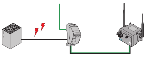
SCALANCE W788-xPRO/RR / SCALANCE W74x-1PRO/RR
Operating Instructions (Compact), Release 08/2007, A5E00413342-05 89
Connecting up 4
4.1 Cabling for power supply and Ethernet
Suitable cables
The following cables are available for connecting a SCALANCE W788-xPRO/RR or
SCALANCE W74x-1PRO/RR to the power supply and Ethernet:
● IE hybrid cable 2 x 2 + 4 x 0.34 (order no. 6XV1870-2J)
The two data wire pairs are separately shielded. This cable is particularly suitable for
assembly with the IE IP 67 hybrid connector.
● IE FC TP standard cable 4 x 2 GP (order no. 6XV1870-2E)
In these cable types, two wires are twisted. All four pairs of wires are inside a common
shield.
● 2 x 2 IE cable, the optional power supply (18 - 48 V DC) is over M12 connectors.
Cable selection and interference exposure
A decisive factor in the selection of a cable type is the electromagnetic interference to which
the current lines between the power supply and the FC RJ-45 modular outlet are subjected.
Due to the separate shielding of the data wires, such interference has less effect on the data
transmission on a hybrid cable than on TP standard cable or TP flexible cable.
AB C
Figure 4-1 Wiring a SCALANCE W788-xPRO/RR with electromagnetic interference between the
power supply and modular outlet
A power supply
B FC RJ-45 modular outlet with power insert
C SCALANCE W788-xPRO/RR
Connecting up
4.2 Lightning protection, power supply, and grounding
SCALANCE W788-xPRO/RR / SCALANCE W74x-1PRO/RR
90 Operating Instructions (Compact), Release 08/2007, A5E00413342-05
4.2 Lightning protection, power supply, and grounding
Notes on lightning protection
WARNING
Danger due to lightning strikes
Antennas installed outdoors must be within the area covered by a lightning protection
system. Make sure that all conducting systems entering from outdoors can be protected by
a lightning protection potential equalization system.
When implementing your lightning protection concept, make sure you adhere to the VDE
0182 or IEC 62305 standard.
A suitable lightning conductor is available in the range of accessories of SIMATIC NET
Industrial WLAN:
Lightning protector LP798-1N (order no. 6GK5798-2LP00-2AA6)
WARNING
Danger due to lightning strikes
Installing this lightning protector between an antenna and a SCALANCE W-700 is not
adequate protection against a lightning strike. The LP798-1N lightening protector only
works within the framework of a comprehensive lightning protection concept. If you have
questions, ask a qualified specialist company.
Note
The requirements of EN61000-4-5, surge immunity tests on power supply lines, are met only
when a Blitzductor is used with 12 - 24 V DC and 48 V DC:
12 - 24 V DC: VT AD 24V type no. 918 402
48 V DC: Type no. 919 545 and 919 506 (holder)
Manufacturer: DEHN+SÖHNE GmbH+Co.KG, Hans Dehn Str. 1, Postfach 1640, D-92306
Neumarkt, Germany

Connecting up
4.2 Lightning protection, power supply, and grounding
SCALANCE W788-xPRO/RR / SCALANCE W74x-1PRO/RR
Operating Instructions (Compact), Release 08/2007, A5E00413342-05 91
Safety extra low voltage
WARNING
Danger to life from overvoltage, fire hazard
SCALANCE W-700 devices are designed for operation with a directly connectable safety
extra-low voltage or with the power supply adapters available as accessories (available
only for the SCALANCE W786-xPRO device). Therefore only safety extra-low voltage
(SELV) with limited power source (LPS) complying with IEC950/EN60950/VDE0805 may
be connected to the power supply terminals (exception: Power supply adapter for 110 - 230
V AC for the SCALANCE W786-xPRO).
Measures must be taken to prevent transient overvoltages of more than 40% of the rated
voltage. This is the case if the devices are operated exclusively with SELV (Safety Extra
Low Voltage).
The power supply unit to supply the SCALANCE W-700 must comply with NEC Class 2
(requirements of class 2 for power supply units of the "National Electrical Code, table 11
(b)") or SELV with LPS (Limited Power Source) EN 60950-1. If the power supply is
designed redundantly (two separate power supplies), both power supplies must meet these
requirements.
Exceptions:
• Power supply with PELV (according to VDE 0100-410 or IEC 60364-4-41) is also
possible if the generated rated voltage does not exceed the voltage limits 25 V AC or 60
V DC.
Earthing
CAUTION
Damage to the device due to potential differences
To avoid the influence of electromagnetic interference, the device should be grounded.
There must be no potential difference between the following parts, otherwise the device or
other connected device could be severely damaged:
• Housing of the SCALANCE W-700 and the ground potential of the antenna.
• Housing of the SCALANCE W-700 and the ground potential of a device connected over
Ethernet.
• Housing of the SCALANCE W-700 and the shield contact of the connected Ethernet
cable.
Connect both grounds to the same foundation earth or use an equipotential bonding cable.
Interruption of the power supply
CAUTION
Damage to the Ethernet interface
Repeated fast removal and insertion of the Ethernet cable when using Power-over-Ethernet
and when there is a redundant power supply can cause damage to the Ethernet interface.
Avoid repeatedly removing and inserting the Ethernet cable when using Power-over-
Ethernet and a redundant power supply.

Connecting up
4.3 Suitable antenna cables and antennas for SCALANCE W-700
SCALANCE W788-xPRO/RR / SCALANCE W74x-1PRO/RR
92 Operating Instructions (Compact), Release 08/2007, A5E00413342-05
4.3 Suitable antenna cables and antennas for SCALANCE W-700
Antenna connector: N-Connect/R-SMA connecting cable
The N-Connect/R-SMA male/male flexible connecting cable is available as an accessory for
direct connection of an antenna to a SCALANCE W-700.
Length in m Order number
1
2
5
10
6XV1875-5CH10
6XV1875-5CH20
6XV1875-5CH50
6XV1875-5CN10
Antenna connector: N-Connect/ N-Connect connecting cable
The N-Connect/N-Connect male/male flexible connecting cable is available as an accessory
for connecting an antenna to the lightning protector LP798-1N.
Length in m Order number
1
2
5
10
6XV1875-5CH10
6XV1875-5CH20
6XV1875-5CH50
6XV1875-5CN10
There is a control cabinet feedthrough available for IWLAN devices located in a control
cabinet. You will find detailed information in the catalog IK PI.

Connecting up
4.3 Suitable antenna cables and antennas for SCALANCE W-700
SCALANCE W788-xPRO/RR / SCALANCE W74x-1PRO/RR
Operating Instructions (Compact), Release 08/2007, A5E00413342-05 93
Antennas
The following antennas have been approved for use with a SCALANCE W-700:
Type Properties Order No.
ANT795-6MN Omni antenna 2.4 / 5 GHz,
ceiling mounted
6GK5795-6MN00-0AA6
ANT792-6MN Omni antenna 2.4 GHz,
wall mounted
6GK5792-6MN00-0AA6
ANT793-6MN Omni antenna 5 GHz,
wall mounted
6GK5793-6MN00-0AA6
ANT792-8DN Directional antenna 2.4 GHz,
wall mounted
6GK5792-8DN00-0AA6
ANT793-8DN Directional antenna 5 GHz,
wall mounted
6GK5793-8DN00-0AA6
ANT795-6DN Directional antenna 2.4 / 5 GHz,
wall mounted
6GK5795-6DN00-0AA6
ANT795-4MR Omni antenna 2.4 / 5 GHz,
mounted directly on a
SCALANCE W788-xPRO/RR or
W74x-1PRO/RR
6GK5795-4MR00-0AA6
ANT795-4MS Omni antenna 2.4 / 5 GHz,
mounted directly on a
SCALANCE W788-xPRO/RR or
W784-1xx or W74x-1PRO/RR
or W74x-1
6GK5795-4MS00-0AA6
ANT792-4DN RCoax antenna 2.4 GHz 6GK5792-4DN00-0AA6
ANT793-4MN RCoax antenna 5 GHz 6GK5793-4MN00-0AA6
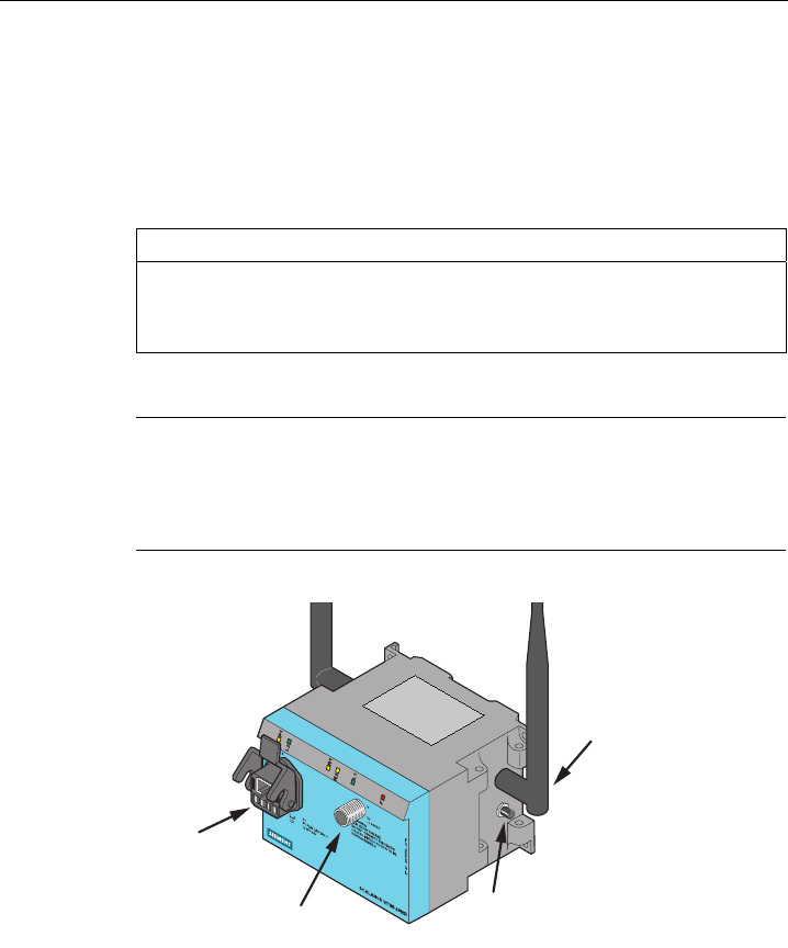
Connecting up
4.4 Connectors for external antennas and power supply
SCALANCE W788-xPRO/RR / SCALANCE W74x-1PRO/RR
94 Operating Instructions (Compact), Release 08/2007, A5E00413342-05
4.4 Connectors for external antennas and power supply
Hybrid female connector and M12 male connector
The SCALANCE W788-xPRO / W788-xRR / W74x-1xx is attached to Ethernet via a hybrid
socket on the front of the housing (position A in the figure). This port also has contacts for
the operating voltage.
CAUTION
Strain relief for the hybrid cable
Make sure that there is strain relief for the hybrid cable socket in both directions (along the
cable axis and transverse). Forces can be exerted on the socket simply from the weight of
the hybrid cable, for example when the SCALANCE W is installed high up.
Note
Protective cap for the hybrid socket
If you do not use the hybrid socket, this must be covered with a protective cap, otherwise IP
65 protection is lost. A suitable protective cap is available as an accessory (order no.
6ES7194-1JB10-0XA0). If you do not use the M12 connector, the supplied protective cap
must also be fitted to retain the IP65 degree of protection.
A
BC
D
Figure 4-2 Connectors of the SCALANCE W788-xPRO/RR or W74x-1PRO/RR. The additional
antenna connectors (position C) only exist for the types W788-2PRO and W788-2RR.
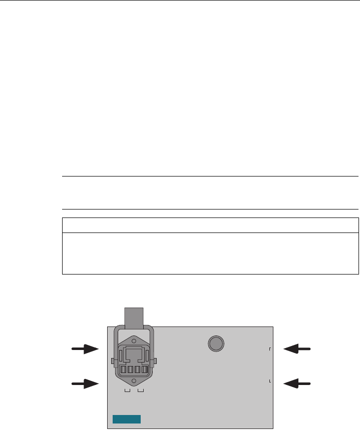
Connecting up
4.4 Connectors for external antennas and power supply
SCALANCE W788-xPRO/RR / SCALANCE W74x-1PRO/RR
Operating Instructions (Compact), Release 08/2007, A5E00413342-05 95
As an alternative or in addition to this, you can also use the M12 plug for the power supply
(position B in the previous figure).
You can fit additional antennas to the sides of the SCALANCE W788-2PRO and
SCALANCE W788-2RR with an antenna cable (position C in the previous figure). If you
install the SCALANCE W788-xPRO/RR or W74x-1PRO/RR in a cabinet, you will need to
unscrew the antennas due to the restricted communication (position D in the figure). In this
case, the connection is over detached antennas installed outside the cabinet. On the front
panel, there is also an identifier for the antenna connectors. The A connectors are on the
right-hand side and B connectors B on the left-hand side.
Suitable connecting cable for a connection between SCALANCE W788-xPRO/RR or W74x-
1PRO/RR and a detached antenna are available from SIMATIC NET. You will find detailed
information in the section "Suitable antenna cables and antennas for the SCALANCE W-
700".
Arrangement of interfaces and connectors
Note
The distance between a pair of antennas for the first and second WLAN interface must be at
least 0.5 m.
NOTICE
Terminating resistor
Each WLAN interface has two antenna connectors. If you use only one connector, make
sure that you connect a terminating resistor to the second connector to ensure trouble-free
operation of the SCALANCE W788-xPRO/RR or W74x-1PRO/RR.
The following figure shows the location of the sockets for the individual interfaces:
SIEMENS
A2
A1
SCALANCE W788-2PRO
S VP JM 123 44-72-22
ML2
X1
P1 FOR LAN ONLY
L2 DC 24V
WARNING:
EXPLOSION HAZARD.
DO NOT CONNECT EQUIPMENT
UNLESS AREA IS KNOWN TO BE
NONHAZARDOUS
M
X2
L1 24VDC
788-1ST00-2AA6
A2 ANTENNA A1
B2
B1
Figure 4-3 Antenna connectors of the SCALANCE W788-xPRO/RR or W74x-1PRO/RR. The
antenna connectors A2 and B2 only exist for the types W788-2PRO and W788-2RR.

Connecting up
4.5 Assembling an IE hybrid cable 2 x 2 + 4 x 0.34 with an IE IP 67 hybrid connector
SCALANCE W788-xPRO/RR / SCALANCE W74x-1PRO/RR
96 Operating Instructions (Compact), Release 08/2007, A5E00413342-05
4.5 Assembling an IE hybrid cable 2 x 2 + 4 x 0.34 with an IE IP 67 hybrid
connector
Procedure
Remove the two inner shells of the universal sealing ring
to adapt it to the diameter of the hybrid cable.
Push the bushing, washer, adapted universal sealing
ring and the housing over the cable jacket.
25 mm
19 mm 11 mm
Remove the following lengths of cable jacket and shield
braid:
• 25 mm for the power leads.
• 30 mm jacket for the data leads (shorten the braid by
11 mm).
Cut off the filler at the height of the cable jacket.
Arrange the data leads according to the color codes on
the splice element. The following table shows the
assignment of the data leads.
Contact 6
(Blue)
Contact 1
(Yellow)
Contact 2
(Orange)
Contact 3
(White)
Contact and color assignment of the splice element.
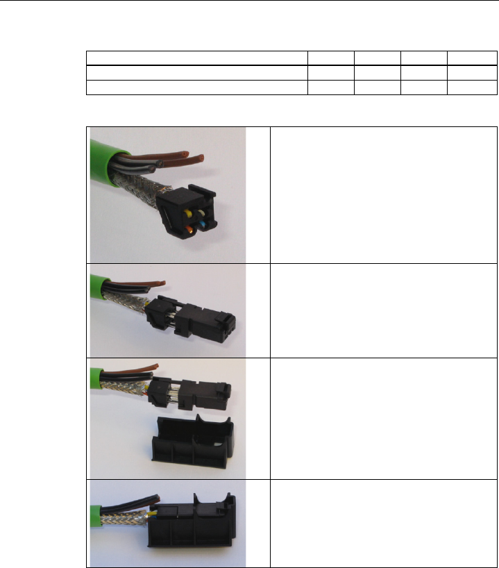
Connecting up
4.5 Assembling an IE hybrid cable 2 x 2 + 4 x 0.34 with an IE IP 67 hybrid connector
SCALANCE W788-xPRO/RR / SCALANCE W74x-1PRO/RR
Operating Instructions (Compact), Release 08/2007, A5E00413342-05 97
Wire color code (standard) White Blue Yellow Orange
Connector color code (Siemens IE) White Blue Yellow Orange
Siemens IE FC RJ-45 socket (reference) 3 6 1 2
Insert the all the data leads at the same time into the
splice element is far as they will go.
Close the splice element and RJ-45 data module until
they lock together.
Insert the data module and the splice element into the
supplied IDC assembly tool.
Press the data module and the IDC assembly tool
together to establish the installation piercing
connection.
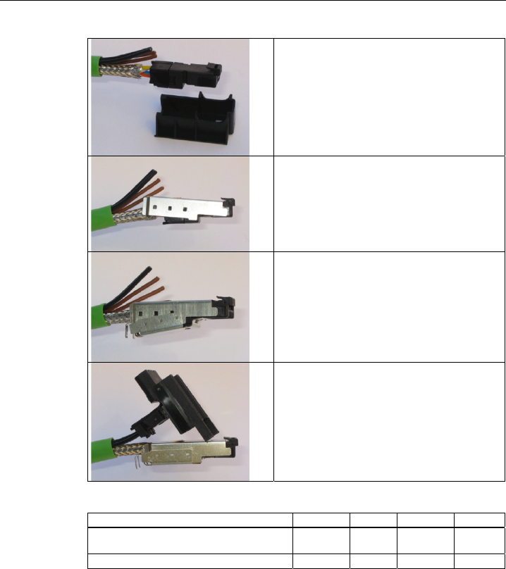
Connecting up
4.5 Assembling an IE hybrid cable 2 x 2 + 4 x 0.34 with an IE IP 67 hybrid connector
SCALANCE W788-xPRO/RR / SCALANCE W74x-1PRO/RR
98 Operating Instructions (Compact), Release 08/2007, A5E00413342-05
Remove the assembled data module from the IDC
assembly tool.
Position the top shield plate and press it over the cable
shield.
Position the lower shield plate and press it and the
upper shield plate together until they lock together with
an audible "click".
Arrange the power leads and insert them as far as they
will go into the hinge elements of the isolation body.
The following table shows the assignment of the power
leads.
Wire color code (standard) Brown Brown Black Black
Function 24 V 48 V PoE Ground Chassis
PoE
Power supply insert module 1 2 3 4
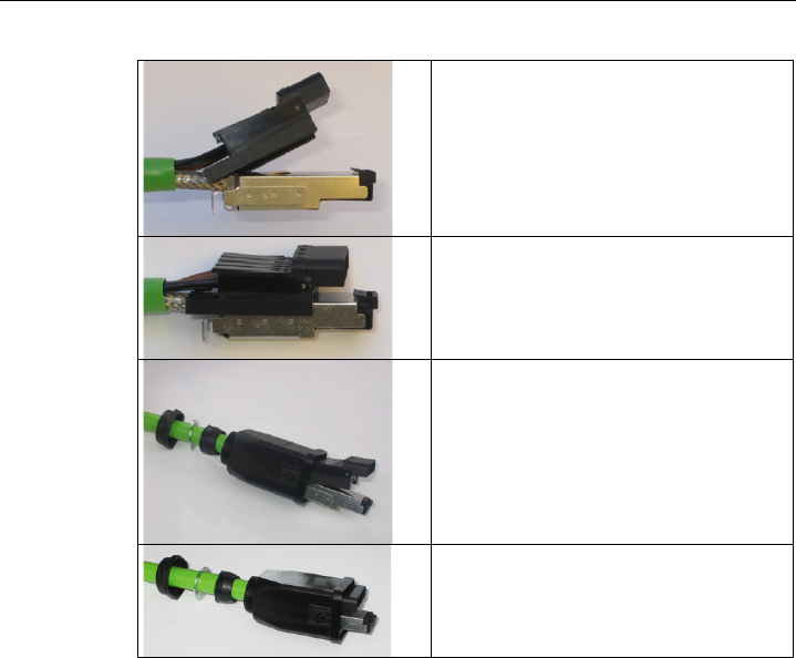
Connecting up
4.5 Assembling an IE hybrid cable 2 x 2 + 4 x 0.34 with an IE IP 67 hybrid connector
SCALANCE W788-xPRO/RR / SCALANCE W74x-1PRO/RR
Operating Instructions (Compact), Release 08/2007, A5E00413342-05 99
Press each individual hinge element together with the
integrated IDC contact.
Push the housing over the assembled data module and
the insulator body until they lock together (there should
be an audible click).
Tighten the cable gland. We recommend an open key
with a size of 21 mm.

Connecting up
4.6 Fitting the IE FC TP standard cable 4 x 2 GP to an IE IP 67 hybrid connector
SCALANCE W788-xPRO/RR / SCALANCE W74x-1PRO/RR
100 Operating Instructions (Compact), Release 08/2007, A5E00413342-05
4.6 Fitting the IE FC TP standard cable 4 x 2 GP to an IE IP 67 hybrid
connector
Procedure
Remove the two inner shells of the universal sealing ring
to adapt it to the diameter of the hybrid cable.
Push the bushing, washer, adapted universal sealing
ring and the housing over the cable jacket.
25 mm
30 mm
Remove the following lengths of cable jacket and shield
braid:
• 25 mm for the power leads
• 30 mm for the data leads
To achieve good shielding, the shield braid must be alt
least 30 mm long.
Arrange the data leads according to the color codes on
the splice element. The following table shows the
assignment of the data leads.
Wind the shield braid around the data leads. As a result,
the shielding of the cable has contact to the shield plate
of the splice element that will be fitted later.

Connecting up
4.6 Fitting the IE FC TP standard cable 4 x 2 GP to an IE IP 67 hybrid connector
SCALANCE W788-xPRO/RR / SCALANCE W74x-1PRO/RR
Operating Instructions (Compact), Release 08/2007, A5E00413342-05 101
Contact 6
(Blue)
Contact 1
(Yellow)
Contact 2
(Orange)
Contact 3
(White)
Contact and color assignment of the splice element.
Color coding of the standard cable White /
orange *
Orange White /
green *
Green
Connector color code (Siemens IE) White Blue Yellow Orange
Siemens IE FC RJ-45 socket (reference) 3 6 1 2
* White wire of the pair.
Insert the all the data leads at the same time into the
splice element is far as they will go.
Close the splice element and RJ-45 data module until
they lock together.
Insert the data module and the splice element into the
supplied IDC assembly tool.
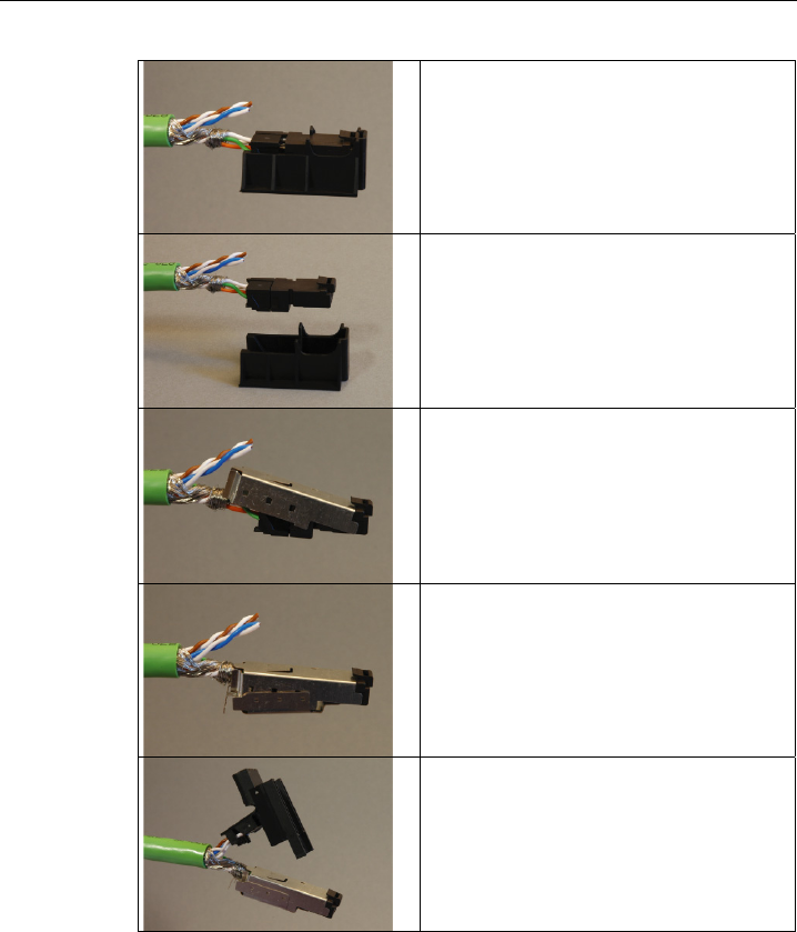
Connecting up
4.6 Fitting the IE FC TP standard cable 4 x 2 GP to an IE IP 67 hybrid connector
SCALANCE W788-xPRO/RR / SCALANCE W74x-1PRO/RR
102 Operating Instructions (Compact), Release 08/2007, A5E00413342-05
Press the data module and the IDC assembly tool
together to establish the installation piercing connection.
Remove the assembled data module from the IDC
assembly tool.
Position the top shield plate and press it over the cable
shield.
Position the lower shield plate and press it and the upper
shield plate together until they lock together with an
audible "click".
Arrange the power leads and insert them as far as they
will go into the hinge elements of the isolation body.
The following table shows the assignment of the power
leads.
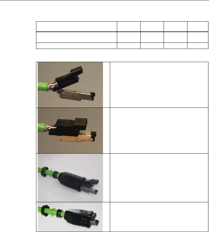
Connecting up
4.6 Fitting the IE FC TP standard cable 4 x 2 GP to an IE IP 67 hybrid connector
SCALANCE W788-xPRO/RR / SCALANCE W74x-1PRO/RR
Operating Instructions (Compact), Release 08/2007, A5E00413342-05 103
Wire color code (standard) White /
blue *
Blue White /
brown *
Brown
Function 24 V 48 V PoE Ground Chassis
PoE
Power supply insert module 1 2 3 4
* White wire of the pair.
Press each individual hinge element together with the
integrated IDC contact.
Recommendation: Use a small slotted screwdriver (max.
3.5 mm) as a lever.
Push the housing over the assembled data module and
the insulator body until they lock together (there should
be an audible click).
Tighten the cable gland. We recommend an open key
with a size of 21 mm.

Connecting up
4.7 Pinning of the M12 male connector
SCALANCE W788-xPRO/RR / SCALANCE W74x-1PRO/RR
104 Operating Instructions (Compact), Release 08/2007, A5E00413342-05
4.7 Pinning of the M12 male connector
Power supply over the M12 connector
The M12 male connector on the front of the SCALANCE W7xx has the following pinning:
Pin Function
Pin 1 24 V DC
Pin 2 --
Pin 3 Ground
Pin 4 --

SCALANCE W788-xPRO/RR / SCALANCE W74x-1PRO/RR
Operating Instructions (Compact), Release 08/2007, A5E00413342-05 105
Technical specifications 5
5.1 Technical specifications for the SCALANCE W788-xPRO/RR and
W74x-1PRO/RR
Device variants
The technical specifications of the
● SIMATIC NET SCALANCE W744-1PRO
● SIMATIC NET SCALANCE W746-1PRO
● SIMATIC NET SCALANCE W747-1RR
● SIMATIC NET SCALANCE W788-1PRO
● SIMATIC NET SCALANCE W788-2PRO
● SIMATIC NET SCALANCE W788-1RR
● SIMATIC NET SCALANCE W788-2RR
are largely identical. Unless indicated otherwise in the table, the following tables apply to all
the devices listed above:
Data transfer
Ethernet transfer rate 10/100 Mbps
Wireless transmission rate 1 ... 54 Mbps (108 Mbps)
Wireless standards supported 802.11a
802.11b
802.11g
802.11h
Power supply standards supported 802.3af (Power over Ethernet)
Interfaces
Note
Bridging a power outage is is possible only with an input voltage of 24 V DC (-15% . . .
+20%).

Technical specifications
5.1 Technical specifications for the SCALANCE W788-xPRO/RR and W74x-1PRO/RR
SCALANCE W788-xPRO/RR / SCALANCE W74x-1PRO/RR
106 Operating Instructions (Compact), Release 08/2007, A5E00413342-05
Power • M12 connector
(24 V DC, 48 V DC)
• Power contacts in the hybrid connector
(24 V DC, 48 V DC)
• RJ-45 jack Power over Ethernet
(48 V DC)
2 x 24 V DC power supplies (24 V DC, 48 V DC)
safety extra-low voltage (SELV).
Power supply isolated according to IEEE 802.3af,
isolation resistance > 2 Mohms.
Back up IE IP 67 hybrid connector
R-SMA antenna sockets
(2 x or 4 x with the 788-2PRO)
Electrical data
Power consumption < 10 W
Construction
Dimensions without antennas
(W x H x L)
125 mm x 88 mm x 108 mm
Weight approx. 1050 g
Permitted ambient conditions
Operating temperature -20°C to 60°C
Transport/storage temperature -40°C to 70°C
Degree of protection Tested to IP65
MTBF information (mean time between failure)
MTBF 67 years

Technical specifications
5.2 Technical specifications ANT795-4MR
SCALANCE W788-xPRO/RR / SCALANCE W74x-1PRO/RR
Operating Instructions (Compact), Release 08/2007, A5E00413342-05 107
5.2 Technical specifications ANT795-4MR
Mechanical characteristics
Connector R-SMA male for connection to
SCALANCE W78x or
SCALANCE W74x
Cover material Polycarbonate
Silicone-free
Electrical characteristics
Frequency range 2.4 ~ 2.4835 GHz
5.15 ~ 5.35 GHz
5.725 ~ 5.85 GHz
Impedance 50 ohms
Voltage standing wave ratio ≤ 2,0
Return loss ≤ -10 dB
Gain at 2.45 GHz 3 dBi
Gain at 5.25 GHz 5 dBi
Polarization Vertical
Ambient temperature - 20 °C.... + 60 °C
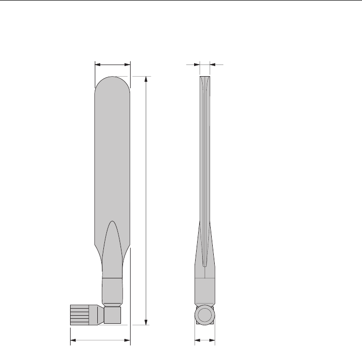
Technical specifications
5.3 Dimension drawing ANT795-4MR
SCALANCE W788-xPRO/RR / SCALANCE W74x-1PRO/RR
108 Operating Instructions (Compact), Release 08/2007, A5E00413342-05
5.3 Dimension drawing ANT795-4MR
21.2
34.6
148
13
6
SCALANCE W788-xPRO/RR / SCALANCE W74x-1PRO/RR
Operating Instructions (Compact), Release 08/2007, A5E00413342-05 109
Certification 6
6.1 Approvals for the SCALANCE W788-xPRO/RR and 74x-1PRO/RR
CE conformity
The products
SIMATIC NET SCALANCE W788-1PRO
SIMATIC NET SCALANCE W788-2PRO
SIMATIC NET SCALANCE W788-1RR
SIMATIC NET SCALANCE W788-2RR
SIMATIC NET SCALANCE W744-1PRO
SIMATIC NET SCALANCE W746-1PRO
SIMATIC NET SCALANCE W747-1RR
in the version put into circulation by Siemens A&D conform to the regulations of the following
European directive:
● 99/5/EC
Directive of the European Parliament and of the Council on radio equipment and
telecommunications terminal equipment and the mutual recognition of their conformity.
Conformity with the basic requirement of the directive is attested by adherence to the
following standards:
● EN 60950
Safety of information technology equipment
● EN 301489-1
Electromagnetic compatibility for radio equipment and services
● EN 301489-17
Specific requirements for broadband data transmission systems and for equipment in
local high-performance wireless networks (HIPERLAN)
● EN 300328
Electromagnetic compatibility and radio spectrum issues
● EN 301893
Broadband radio access networks (BRAN) – 5 GHz high-performance RLAN
● EN 50371
Compliance of low power electronic and electrical apparatus with the basic restrictions
related to human exposure to electromagnetic fields (10 MHz to 300 GHz)
● 1999/519/EC
Council recommendation on the limitation of exposure of the general public to
electromagnetic fields (0 Hz to 300 GHz)

Certification
6.1 Approvals for the SCALANCE W788-xPRO/RR and 74x-1PRO/RR
SCALANCE W788-xPRO/RR / SCALANCE W74x-1PRO/RR
110 Operating Instructions (Compact), Release 08/2007, A5E00413342-05
Devices connected to the system must meet the relevant safety regulations.
The EC Declaration of Conformity is available for the responsible authorities according to the
above-mentioned EC Directive at the following address:
Siemens Aktiengesellschaft
Automation and Drives
Industrielle Kommunikation
Postfach 4848
D-90327 Nürnberg
This declaration certifies compliance with the directives named above, but does not
guarantee any specific properties.
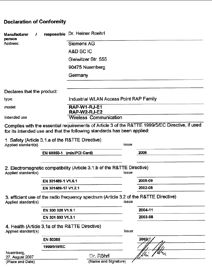
Certification
6.1 Approvals for the SCALANCE W788-xPRO/RR and 74x-1PRO/RR
SCALANCE W788-xPRO/RR / SCALANCE W74x-1PRO/RR
Operating Instructions (Compact), Release 08/2007, A5E00413342-05 111
Certification
6.1 Approvals for the SCALANCE W788-xPRO/RR and 74x-1PRO/RR
SCALANCE W788-xPRO/RR / SCALANCE W74x-1PRO/RR
112 Operating Instructions (Compact), Release 08/2007, A5E00413342-05
ATEX, cULus and FM approvals
The products
SIMATIC NET SCALANCE W788-1PRO
SIMATIC NET SCALANCE W788-2PRO
SIMATIC NET SCALANCE W788-1RR
SIMATIC NET SCALANCE W788-2RR
SIMATIC NET SCALANCE W744-1PRO
SIMATIC NET SCALANCE W746-1PRO
SIMATIC NET SCALANCE W747-1RR
have the following approvals
● EN 60079-15
II 3 G Ex nA II T..
KEMA 07 ATEX 0145X
● c-UL-us:
UL 60950-1 CSA C22.2 No. 60950-1
● c-UL-us for hazardous location*:
ISA 12.12.01-2000, CSA C22.2 No. 213-M1987
CL. 1, Div. 2 GP. A.B.C.D T..
CL. 1, Zone 2, GP, IIC, T..
CL. 1, Zone 2, AEx nC IIC T..
● FM 3611 Hazardous (Classified) Location Electrical Equipment:
Non Incendive / Class I / Division 2 / Groups A,B,C,D / T* and
Non Incendive / Class I / Zone 2 / Group IIC / T*
(T.. / T* = you will find concrete information on the temperature class on the type plate)
WARNING
When used under hazardous conditions (Zone 2), the SCALANCE W788-xPRO/RR or
W74x-1PRO/RR product must be installed in an enclosure. To comply with EN 50021, this
enclosure must meet the requirements of at least IP 54 in compliance with EN 60529.
DO NOT DISCONNECT EQUIPMENT WHEN A FLAMMABLE OR COMBUSTIBLE
ATMOSPHERE IS PRESENT.
Note
The specified approvals apply only when the corresponding mark is printed on the product.

Certification
6.1 Approvals for the SCALANCE W788-xPRO/RR and 74x-1PRO/RR
SCALANCE W788-xPRO/RR / SCALANCE W74x-1PRO/RR
Operating Instructions (Compact), Release 08/2007, A5E00413342-05 113
FCC approval
This device complies with Part 15 of the FCC Rules and with RSS-210 of Industry Canada.
Operation is subject to the following two conditions:
(1) this device may not cause harmful interference, and
(2) this device must accept any interference received, including interference that may cause
undesired operation.
__________________________________________________________________________________
Notice
Changes or modifications made to this equipment not expressly approved by SIEMENS may
void the FCC authorization to operate this equipment.
__________________________________________________________________________________
This equipment has been tested and found to comply with the limits for a Class B digital
device, pursuant to Part 15 of the FCC Rules. These limits are designed to provide
reasonable protection against harmful interference in a residential installation. This
equipment generates, uses and can radiate radio frequency energy and, if not installed and
used in accordance with the instructions, may cause harmful interference to radio
communications. However, there is no guarantee that interference will not occur in a
particular installation. If this equipment does cause harmful interference to radio or television
reception, which can be determined by turning the equipment off and on, the user is
encouraged to try to correct the interference by one or more of the following measures:
● Reorient or relocate the receiving antenna.
● Increase the separation between the equipment and receiver.
● Connect the equipment into an outlet on a circuit different from that to which the receiver
is connected.
Consult the dealer or an experienced radio/TV technician for help.
__________________________________________________________________________________
Notice
This equipment complies with FCC radiation exposure limits set forth for an uncontrolled
environment. This equipment should be installed and operated with minimum distance 20 cm
between the radiator and your body.
This transmitter must not be co-located or operating in conjunction with any other antenna or
transmitter.
__________________________________________________________________________________

Certification
6.2 National approvals for the SCALANCE W788-xPRO/RR / W74x-1PRO/RR
SCALANCE W788-xPRO/RR / SCALANCE W74x-1PRO/RR
114 Operating Instructions (Compact), Release 08/2007, A5E00413342-05
6.2 National approvals for the SCALANCE W788-xPRO/RR /
W74x-1PRO/RR
National approvals
Below, you will find the channels approved by the Institute of Electrical and Electronics
Engineers, Inc. (IEEE) that can be used by SCALANCE W788-xPRO/RR- or W74x-
1PRO/RR devices.
Column Meaning
Country Country
Mode IEEE 802.11 standard and the TPC and / or DFS functionality, where required
CH Channel
MHz Frequency
PWR (EIRP) Maximum permitted effective isotropic radiated power
Use Permitted use indoors and / or outdoors

Certification
6.2 National approvals for the SCALANCE W788-xPRO/RR / W74x-1PRO/RR
SCALANCE W788-xPRO/RR / SCALANCE W74x-1PRO/RR
Operating Instructions (Compact), Release 08/2007, A5E00413342-05 115
The products SCALANCE W788-xPRO/RR- or W74x-1PRO/RR are approved in the
following countries:
Country Mode CH MHz PWR
(EIRP)
Use
Belgium
Denmark
Germany
Finland
Greece
Great Britain
Ireland
Iceland
Italy
Liechtenstein
Luxembourg
The Netherlands
Norway
Austria
Poland
Portugal
Romania
Sweden
Switzerland
Slovakia
Slovenia
Spain
Hungary
11b 11g
g-Turbo
11a
TPC
11h
DFS+TPC
DFS+TPC
1
-
13
36
-
48
36
-
64
100
-
140
2412
-
2472
5180
-
5240
5180
-
5320
5500
-
5700
100 mW
60 mW
200 mW
1000 mW
Indoor + outdoor
Indoor only
Indoor only
Indoor + outdoor
Bulgaria 11b 11g
g-Turbo
11h
DFS+TPC
DFS+TPC
1
-
13
36
-
56
100
-
140
2412
-
2472
5180
-
5280
5500
-
5700
100 mW
200 mW
1000 mW
Indoor + outdoor
Indoor only
Indoor + outdoor
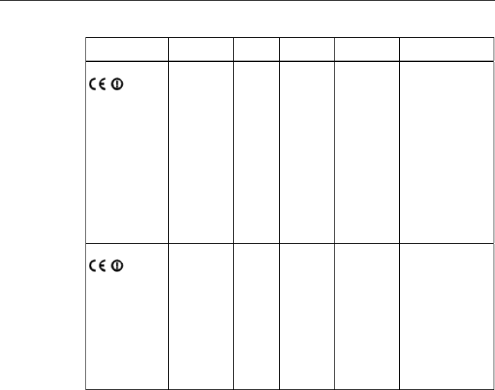
Certification
6.2 National approvals for the SCALANCE W788-xPRO/RR / W74x-1PRO/RR
SCALANCE W788-xPRO/RR / SCALANCE W74x-1PRO/RR
116 Operating Instructions (Compact), Release 08/2007, A5E00413342-05
Country Mode CH MHz PWR
(EIRP)
Use
France
11b 11g
g-Turbo
11a
TPC
11h
DFS+TPC
1
-
7
8
-
13
36
-
48
36
-
64
2412
-
2442
2447
-
2472
5180
-
5240
5180
-
5320
100 mW
100 mW
60 mW
200 mW
Indoor + outdoor
Indoor only
Indoor only
Indoor only
Czech Republic
11b 11g
g-Turbo
11a
TPC
11h
DFS+TPC
1
-
13
36
-
48
36
-
64
2412
-
2472
5180
-
5240
5180
-
5320
100 mW
60 mW
200 mW
Indoor + outdoor
Indoor only
Indoor only
Certification
6.2 National approvals for the SCALANCE W788-xPRO/RR / W74x-1PRO/RR
SCALANCE W788-xPRO/RR / SCALANCE W74x-1PRO/RR
Operating Instructions (Compact), Release 08/2007, A5E00413342-05 117
National approvals for device variants
Modified national approvals apply to the devices in the following table.
Type Order no. Order no. US variant
W788-1PRO 6GK5788-1ST00-2AA6 6GK5788-1ST00-2AB6
W788-2PRO 6GK5788-2ST00-2AA6 6GK5788-2ST00-2AB6
W788-1RR 6GK5788-1SR00-2AA6 6GK5788-1SR00-2AB6
W788-2RR 6GK5788-2SR00-2AA6 6GK5788-2SR00-2AB6
W744-1PRO 6GK5744-1ST00-2AA6 6GK5744-1ST00-2AB6
W746-1PRO 6GK5746-1ST00-2AA6 6GK5746-1ST00-2AB6
W747-1RR 6GK5747-1SR00-2AA6 6GK5747-1SR00-2AB6
These devices are approved in the following countries:
Country Mode CH MHz PWR
(EIRP)
Use
Argentina 11b
11a
TPC
TPC
1
-
13
56
-
64
149
-
161
2412
-
2472
5280
-
5320
5745
-
5805
<
100 mW
50 mW
1000 mW
Indoor + outdoor
Indoor + outdoor
Indoor + outdoor
Australia
11b 11g
g-Turbo
11a
TPC
TPC
11a-Turbo
TPC
TPC
TPC
TPC
TPC
1
-
13
36
-
64
149
-
165
42
50
58
152
160
2412
-
2472
5180
5320
5745
-
5825
5210
5250
5290
5760
5800
100 mW
200 mW
1000 mW
50 mW
200 mW
200 mW
1000 mW
1000 mW
100 mW
200 mW
1000 mW
50 mW
200 mW
200 mW
1000 mW
1000 mW
Certification
6.2 National approvals for the SCALANCE W788-xPRO/RR / W74x-1PRO/RR
SCALANCE W788-xPRO/RR / SCALANCE W74x-1PRO/RR
118 Operating Instructions (Compact), Release 08/2007, A5E00413342-05
Country Mode CH MHz PWR
(EIRP)
Use
Belgium
11b 11g
g-Turbo
11a
TPC
11h
DFS+TPC
DFS+TPC
1
-
13
36
-
48
36
-
64
100
-
140
2412
-
2472
5180
-
5240
5180
-
5320
5500
-
5700
100 mW
60 mW
200 mW
1000 mW
Indoor only
Indoor only
Indoor only
Indoor + outdoor
Brazil 11b
11h
DFS+TPC
DFS+TPC
DFS+TPC
1
-
13
36
-
48
52
-
64
149
-
165
2412
-
2472
5180
-
5240
5260
-
5320
5745
-
5825
400 mW
50 mW
100 mW
1000 mW
Indoor + outdoor
Indoor only
Indoor only
Indoor only
Bulgaria 11b 11g
g-Turbo
11h
DFS+TPC
DFS+TPC
1
-
13
36
-
56
100
-
140
2412
-
2472
5180
-
5280
5500
-
5700
100 mW
200 mW
1000 mW
Indoor + outdoor
Indoor only
Indoor + outdoor

Certification
6.2 National approvals for the SCALANCE W788-xPRO/RR / W74x-1PRO/RR
SCALANCE W788-xPRO/RR / SCALANCE W74x-1PRO/RR
Operating Instructions (Compact), Release 08/2007, A5E00413342-05 119
Country Mode CH MHz PWR
(EIRP)
Use
Chile 11b
11h
DFS+TPC
DFS+TPC
DFS+TPC
11h-Turbo
DFS+TPC
DFS+TPC
DFS+TPC
DFS+TPC
DFS+TPC
1
-
13
36
-
48
52
-
64
149
-
165
42
50
58
152
160
2412
-
2472
5180
-
5240
5260
-
5320
5745
-
5825
5210
5250
5290
5760
5800
100 mW
100 mW
100 mW
100 mW
100 mW
100 mW
100 mW
100 mW
100 mW
Indoor only
Indoor only
Indoor + outdoor
Indoor only
Indoor only
Indoor + outdoor
Indoor + outdoor
Indoor only
Indoor only
China 11b 11g
g-Turbo
11a
TPC
1
-
13
149
-
165
2412
-
2472
5745
-
5825
100 mW
500 mW
Indoor + outdoor
Indoor + outdoor
Certification
6.2 National approvals for the SCALANCE W788-xPRO/RR / W74x-1PRO/RR
SCALANCE W788-xPRO/RR / SCALANCE W74x-1PRO/RR
120 Operating Instructions (Compact), Release 08/2007, A5E00413342-05
Country Mode CH MHz PWR
(EIRP)
Use
Denmark
Germany
Finland
Greece
Great Britain
Ireland
Iceland
Italy
Liechtenstein
Luxembourg
The Netherlands
Norway
Austria
Poland
Portugal
Sweden
Switzerland
Slovakia
Slovenia
Spain
Hungary
11b 11g
g-Turbo
11a
TPC
11h
DFS+TPC
DFS+TPC
1
-
13
36
-
48
36
-
64
100
-
140
2412
-
2472
5180
-
5240
5180
-
5320
5500
-
5700
100 mW
60 mW
200 mW
1000 mW
Indoor + outdoor
Indoor only
Indoor only
Indoor + outdoor
France
11b 11g
g-Turbo
11a
TPC
11h
DFS+TPC
1
-
7
8
-
13
36
-
48
36
-
64
100
-
140
2412
-
2442
2447
-
2472
5180
-
5240
5180
-
5320
5500
-
5700
100 mW
100 mW
60 mW
200 mW
1000 mW
Indoor + outdoor
Indoor only
Indoor only
Indoor only
Indoor + outdoor

Certification
6.2 National approvals for the SCALANCE W788-xPRO/RR / W74x-1PRO/RR
SCALANCE W788-xPRO/RR / SCALANCE W74x-1PRO/RR
Operating Instructions (Compact), Release 08/2007, A5E00413342-05 121
Country Mode CH MHz PWR
(EIRP)
Use
Hong Kong 11b 11g
g-Turbo
11a
TPC
TPC
11a-Turbo
TPC
1
-
13
36
-
64
149
-
165
42
50
58
152
160
2412
-
2472
5180
-
5320
5745
-
5825
5210
5250
5290
5760
5800
100 mW
200 mW
1000 mW
50 mW
200 mW
200 mW
1000 mW
1000 mW
Indoor + outdoor
Indoor + outdoor
Indoor + outdoor
Indoor + outdoor
Indoor + outdoor
Indoor + outdoor
Indoor + outdoor
Indoor + outdoor
India 11b 11g
g-Turbo
1
-
13
2412
-
2472
100 mW
Indoor only
Japan
11b 11g
11a
TPC
TPC
TPC
1
-
14
184
-
196
8
-
16
36
-
48
2412
-
2484
4920
-
4980
5040
-
5080
5180
-
5240
100 mW
200 mW
200 mW
200 mW
Indoor + outdoor
Indoor + outdoor
Indoor + outdoor
Indoor only

Certification
6.2 National approvals for the SCALANCE W788-xPRO/RR / W74x-1PRO/RR
SCALANCE W788-xPRO/RR / SCALANCE W74x-1PRO/RR
122 Operating Instructions (Compact), Release 08/2007, A5E00413342-05
Country Mode CH MHz PWR
(EIRP)
Use
Japan Old 11b 11g
11a
TPC
TPC
TPC
1
-
14
184
-
196
8
-
16
34
-
46
2412
-
2484
4920
-
4980
5040
-
5080
5170
-
5230
100 mW
200 mW
200 mW
200 mW
Indoor + outdoor
Indoor + outdoor
Indoor + outdoor
Indoor only
Canada 11b 11g
g-Turbo
11a
TPC
TPC
11a-Turbo
TPC
TPC
TPC
TPC
TPC
1
-
11
36
-
48
149
-
161
42
50
58
152
160
2412
-
2462
5180
-
5240
5745
-
5805
5210
5250
5290
5760
5800
500 mW
100 mW
1000 mW
50 mW
200 mW
200 mW
1000 mW
1000 mW
Indoor + outdoor
Indoor only
Indoor only
Indoor only
Indoor + outdoor
Indoor + outdoor
Indoor + outdoor
Indoor + outdoor
Korea
11b 11g
1
-
13
2412
-
2472
100 mW
Indoor + outdoor
Kuwait 11b 11g
g-Turbo 1
-
13
2412
-
2472
100 mW
Indoor + outdoor

Certification
6.2 National approvals for the SCALANCE W788-xPRO/RR / W74x-1PRO/RR
SCALANCE W788-xPRO/RR / SCALANCE W74x-1PRO/RR
Operating Instructions (Compact), Release 08/2007, A5E00413342-05 123
Country Mode CH MHz PWR
(EIRP)
Use
Malaysia 11b 11g
11a
TPC
TPC
1
-
13
56
-
64
149
-
165
2412
-
2472
5280
-
5320
5745
-
5825
100 mW
200 mW
1000 mW
Indoor + Outdoor
Indoor only
Indoor + Outdoor
Russia 11b 11g
g-Turbo 1
-
13
2412
-
2472
100 mW
Indoor + outdoor
Singapore 11b 11g
g-Turbo
11h
DFS+TPC
DFS+TPC
11h-Turbo
DFS+TPC
1
-
13
36
-
64
149
-
165
42
50
58
152
160
2412
-
2472
5180
-
5320
5745
-
5825
5210
5250
5290
5760
5800
100 mW
100 mW
100 mW
100 mW
Indoor + outdoor
Indoor + outdoor
Indoor + outdoor
Indoor + outdoor
South Africa 11b 11g
g-Turbo
11a
TPC
11h
DFS+TPC
DFS+TPC
1
-
13
36
-
48
36
-
64
100
-
140
2412
-
2472
5180
-
5240
5180
-
5320
5500
-
5700
100 mW
60 mW
200 mW
1000 mW
Indoor + outdoor
Indoor + outdoor
Indoor only
Indoor + outdoor
Certification
6.2 National approvals for the SCALANCE W788-xPRO/RR / W74x-1PRO/RR
SCALANCE W788-xPRO/RR / SCALANCE W74x-1PRO/RR
124 Operating Instructions (Compact), Release 08/2007, A5E00413342-05
Country Mode CH MHz PWR
(EIRP)
Use
Czech Republic
11b 11g
g-Turbo
11a
TPC
11h
DFS+TPC
1
-
13
36
-
48
36
-
64
2412
-
2472
5180
-
5240
5180
-
5320
100 mW
60 mW
200 mW
Indoor + outdoor
Indoor only
Indoor only
Turkey 11b 11g
g-Turbo
11a
TPC
11h
DFS+TPC
1
-
13
36
-
48
36
-
64
2412
-
2472
5180
-
5240
5180
-
5320
100 mW
60 mW
200 mW
Indoor + outdoor
Indoor only
Indoor only
United Arab
Emirates
11b 11g
g-Turbo
1
-
13
2412
-
2472
100 mW Indoor + Outdoor
United States of
America
11b 11g
g-Turbo
11a
TPC
TPC
11a-Turbo
TPC
TPC
1
-
11
36
-
48
149
-
165
152
160
2412
-
2462
5180
-
5240
5745
-
5825
5760
5800
500 mW
50 mW
1000 mW
1000 mW
1000 mW
Indoor + outdoor
Indoor only
Indoor + outdoor
Indoor + outdoor
Indoor + outdoor
Note
This note and the following table applies only to Japan.
• The antennas in the list below ship with the specified preassembled cable lengths.
• The specified cable lengths must not be reduced.

Certification
6.2 National approvals for the SCALANCE W788-xPRO/RR / W74x-1PRO/RR
SCALANCE W788-xPRO/RR / SCALANCE W74x-1PRO/RR
Operating Instructions (Compact), Release 08/2007, A5E00413342-05 125
Antenna Frequency (MHz) EIRP (dBm/MHz) Restrictions to the approval
(necessary cable attenuation)
ANT795-4MR 2400-2483,5
2471-2497
5150-5250
4900-5000
5030-5091
≤ 12.14 dBm/MHz None
ANT795-6MR 2400-2483,5
2471-2497
≤ 12.14 dBm/MHz 3.9 dB/5 m
(0.78 dB/m)
ANT795-6MR 5150-5250 ≤ 10 dBm/MHz 3.7 dB/5 m
(0.74 dB/m)
ANT795-6MR 4900-5000
5030-5091
≤ 10 dBm/MHz 3.7 dB/5 m
(0.74 dB/m)
ANT792-8DR 2400-2483,5
2471-2497
≤ 22.14 dBm/MHz None
ANT793-8DR 5150-5250 ≤ 10 dBm/MHz 14.4 dB/12 m
(1.2 dB/m)
ANT793-8DR 4900-5000
5030-5091
≤ 20 dBm/MHz 6 dB/5 m
(0.83 dB/m)
ANT792-4DN 2400-2483,5
2471-2497
≤ 12.14 dBm/MHz None

Certification
6.2 National approvals for the SCALANCE W788-xPRO/RR / W74x-1PRO/RR
SCALANCE W788-xPRO/RR / SCALANCE W74x-1PRO/RR
126 Operating Instructions (Compact), Release 08/2007, A5E00413342-05