Siemens RF280R RFID Reader 13.56 MHz User Manual SIMATIC RF200
Siemens AG RFID Reader 13.56 MHz SIMATIC RF200
UserManual.wiki
>
Siemens
>
RF280R User Manual
>
SYH_RF200_76_Part 1
Contents
1.
SYH_RF200_76_Part 1
2.
SYH_RF200_76_Part 2
3.
SYH_RF200_76_Part 3
SYH_RF200_76_Part 1
Navigation menu
Upload a User Manual
Namespaces
Wiki Guide
HTML
PDF
Info
Views
User Manual
Discussion / Help
Navigation
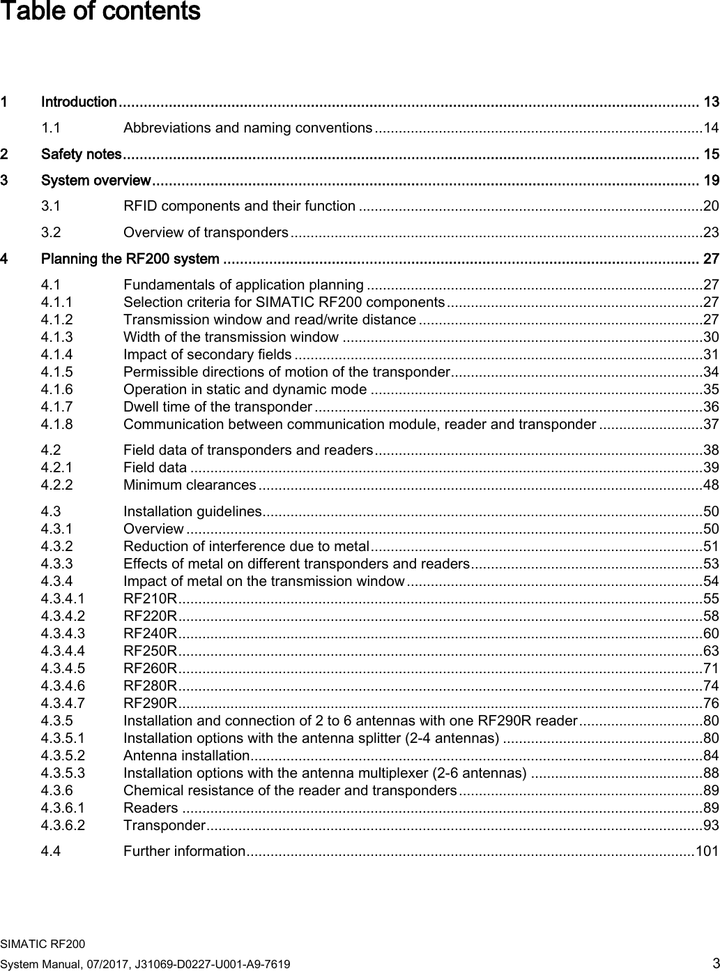
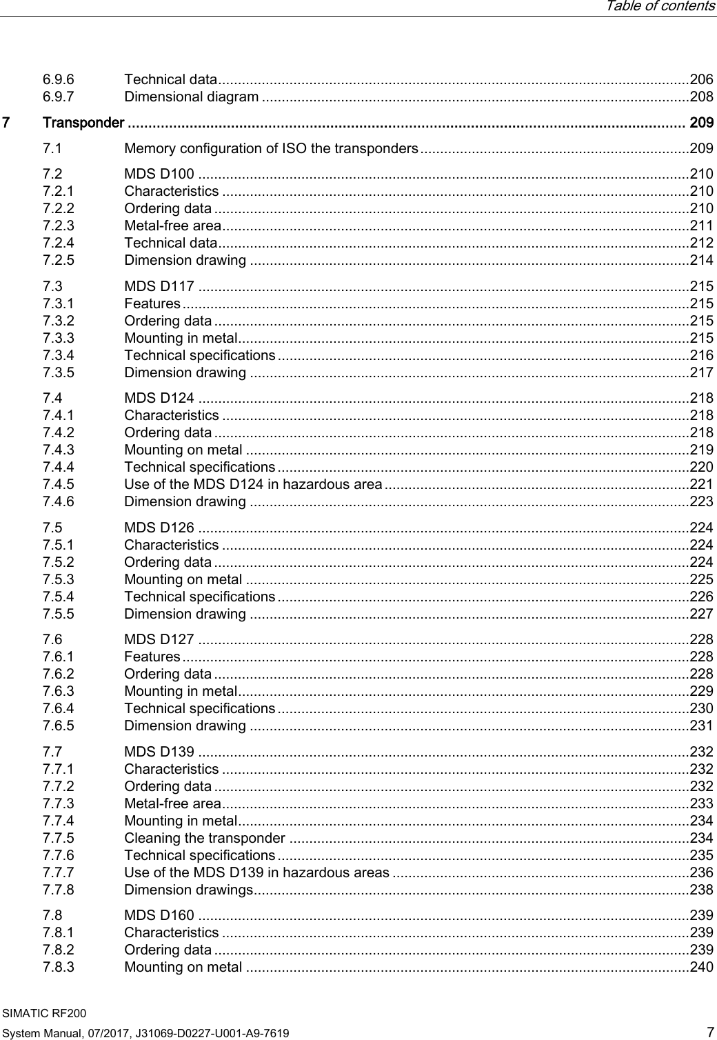


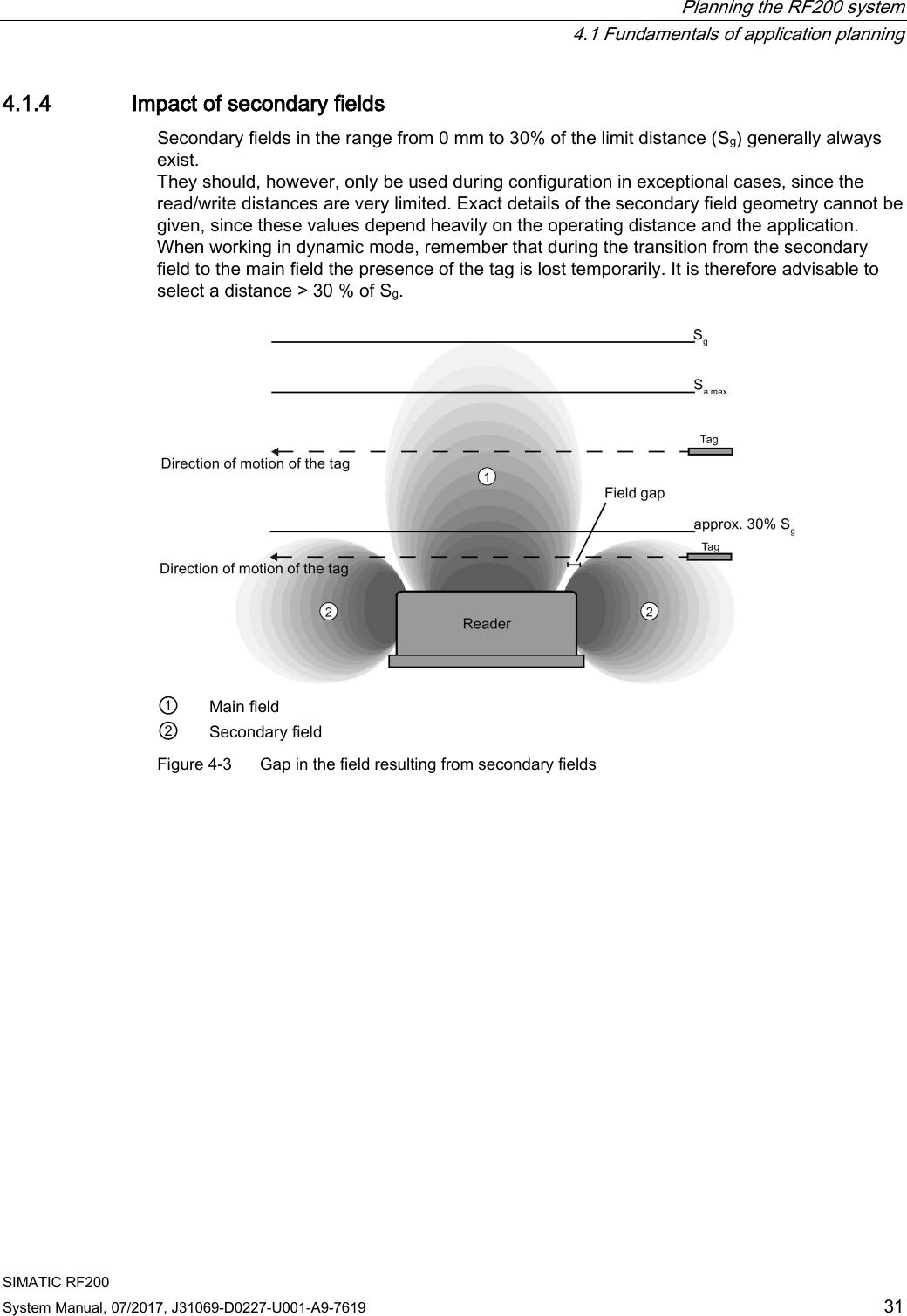
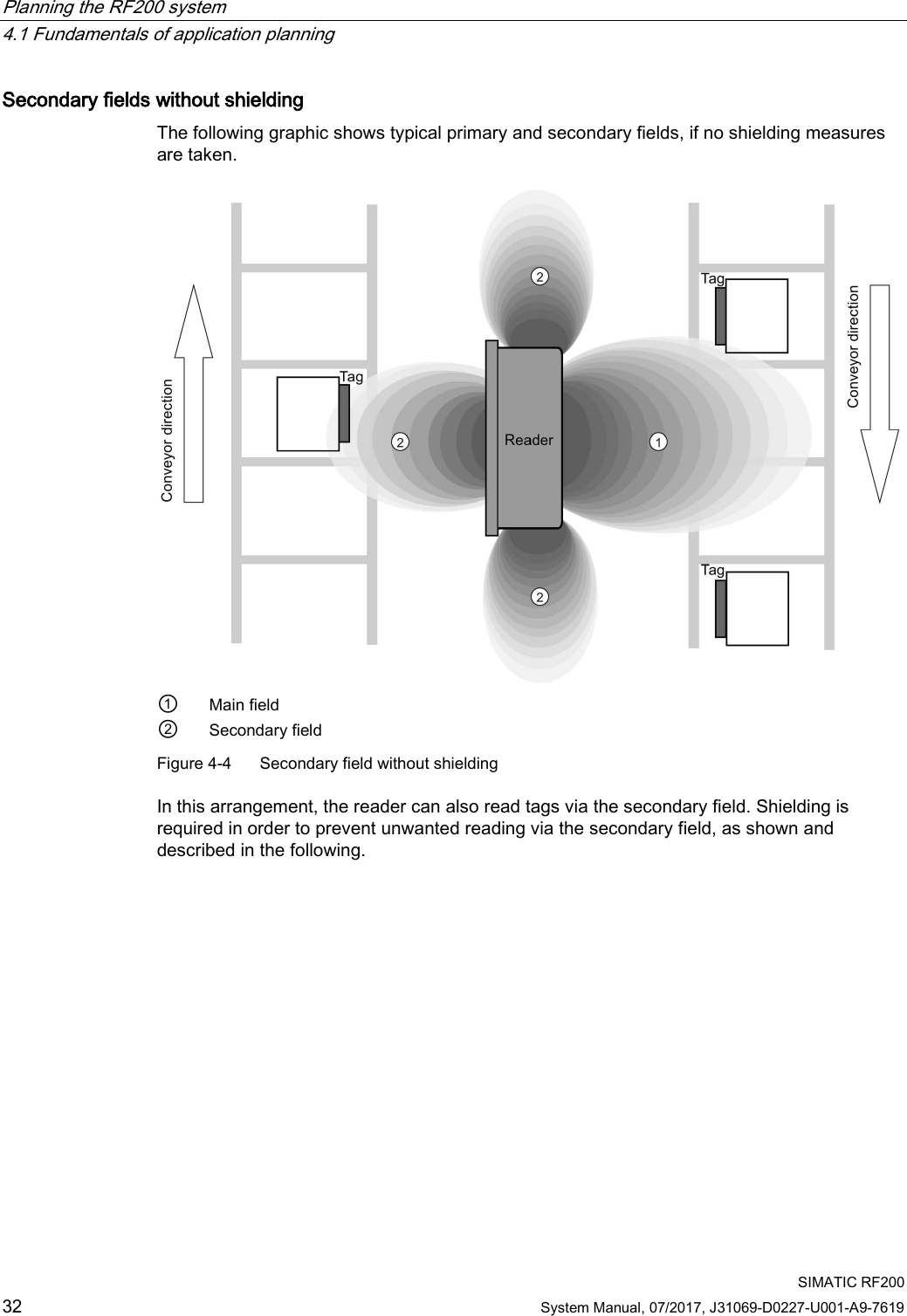
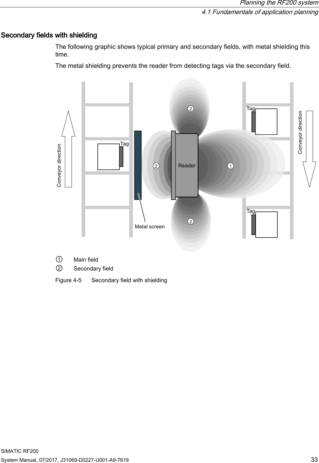
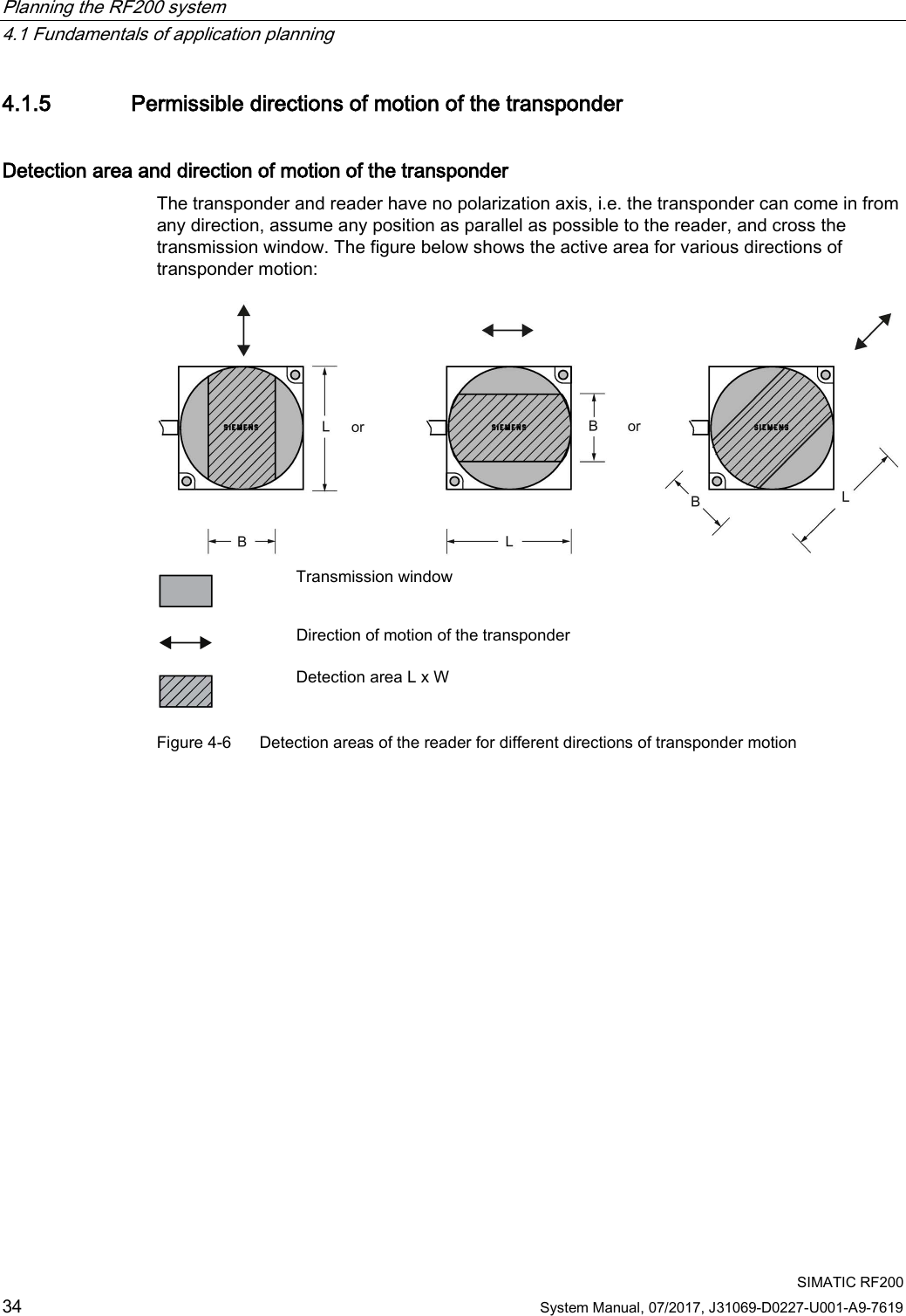
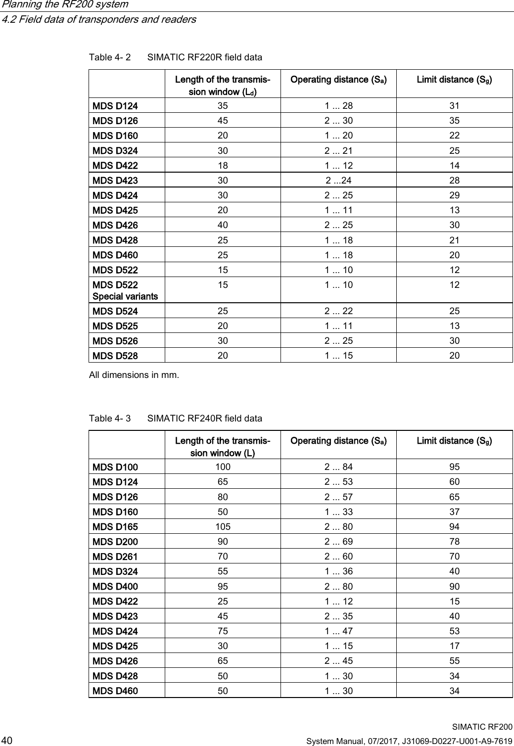
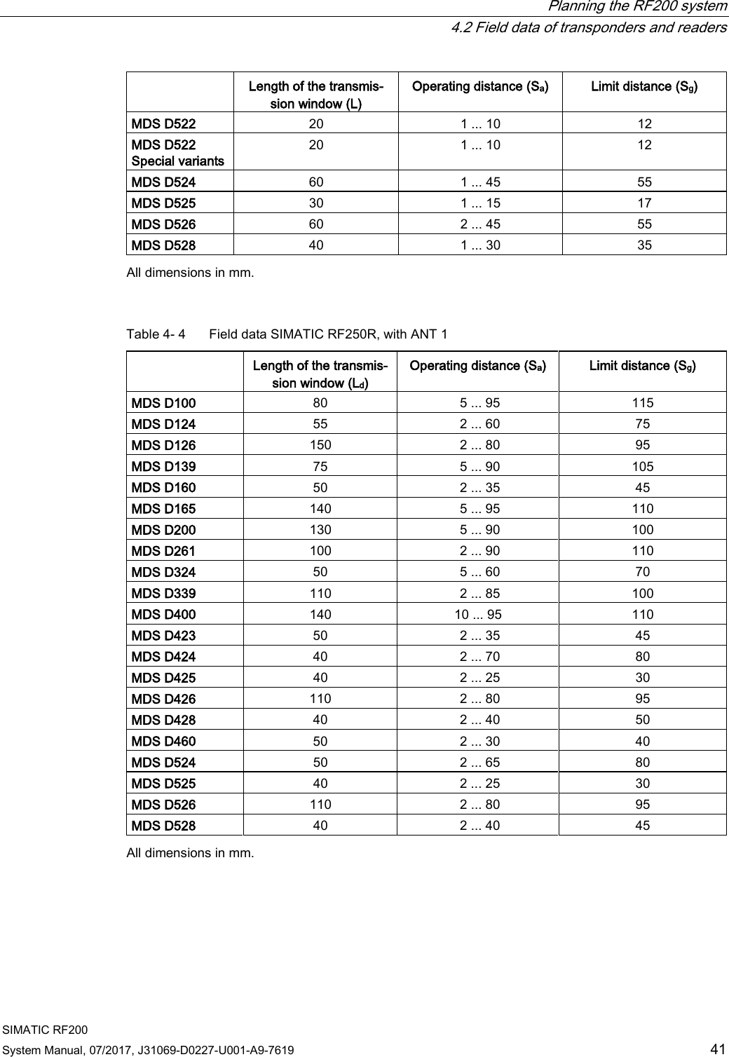
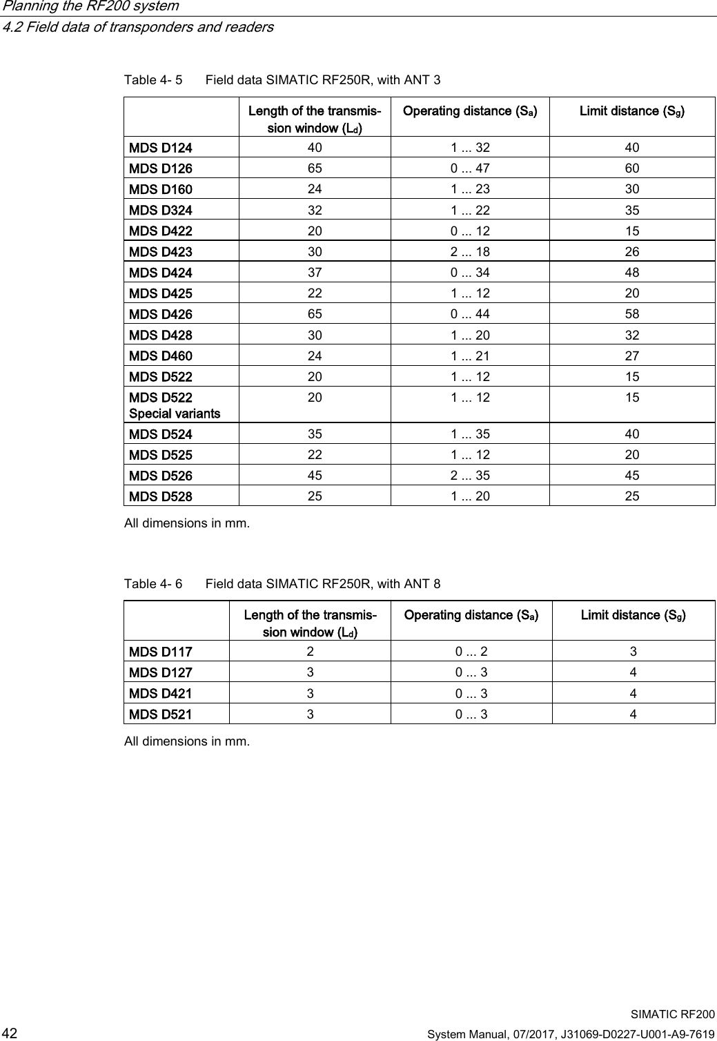
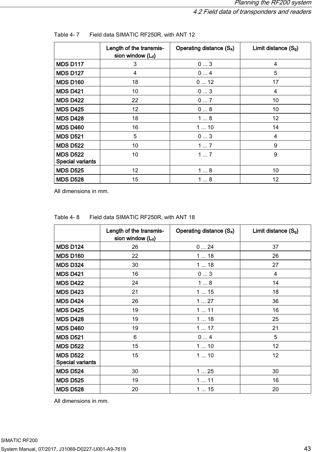
![Planning the RF200 system 4.1 Fundamentals of application planning SIMATIC RF200 System Manual, 07/2017, J31069-D0227-U001-A9-7619 35 4.1.6 Operation in static and dynamic mode Operation in static mode If working in static mode, the transponder can be operated up to the limit distance (Sg). The transponder must then be positioned exactly over the reader: Figure 4-7 Operation in static mode Note Note that in a metallic environment the values for the limit distance are reduced. Operation in dynamic mode When working in dynamic mode, the transponder moves past the reader. The transponder can be used as soon as the intersection (SP) of the transponder enters the circle of the transmission window. In dynamic mode, the operating distance (Sa) is of primary importance. [Operating distances, see Chapter Field data of transponders and readers (Page 38)] Figure 4-8 Operation in dynamic mode](https://usermanual.wiki/Siemens/RF280R.SYH-RF200-76-Part-1/User-Guide-3592552-Page-35.png)
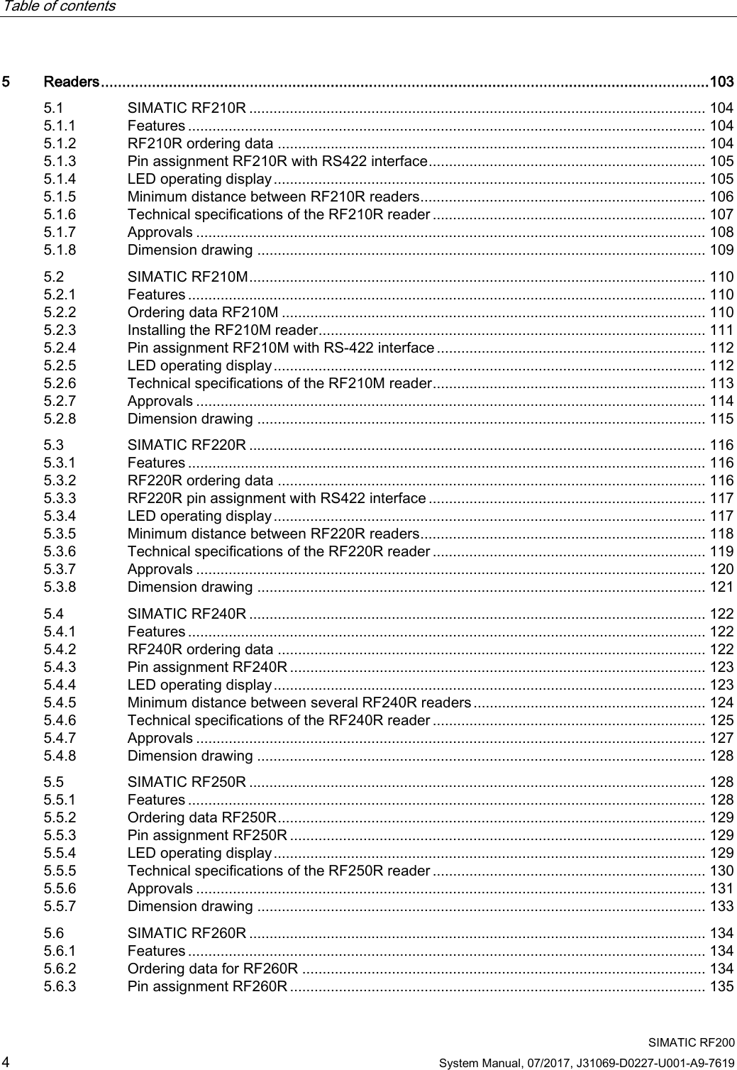
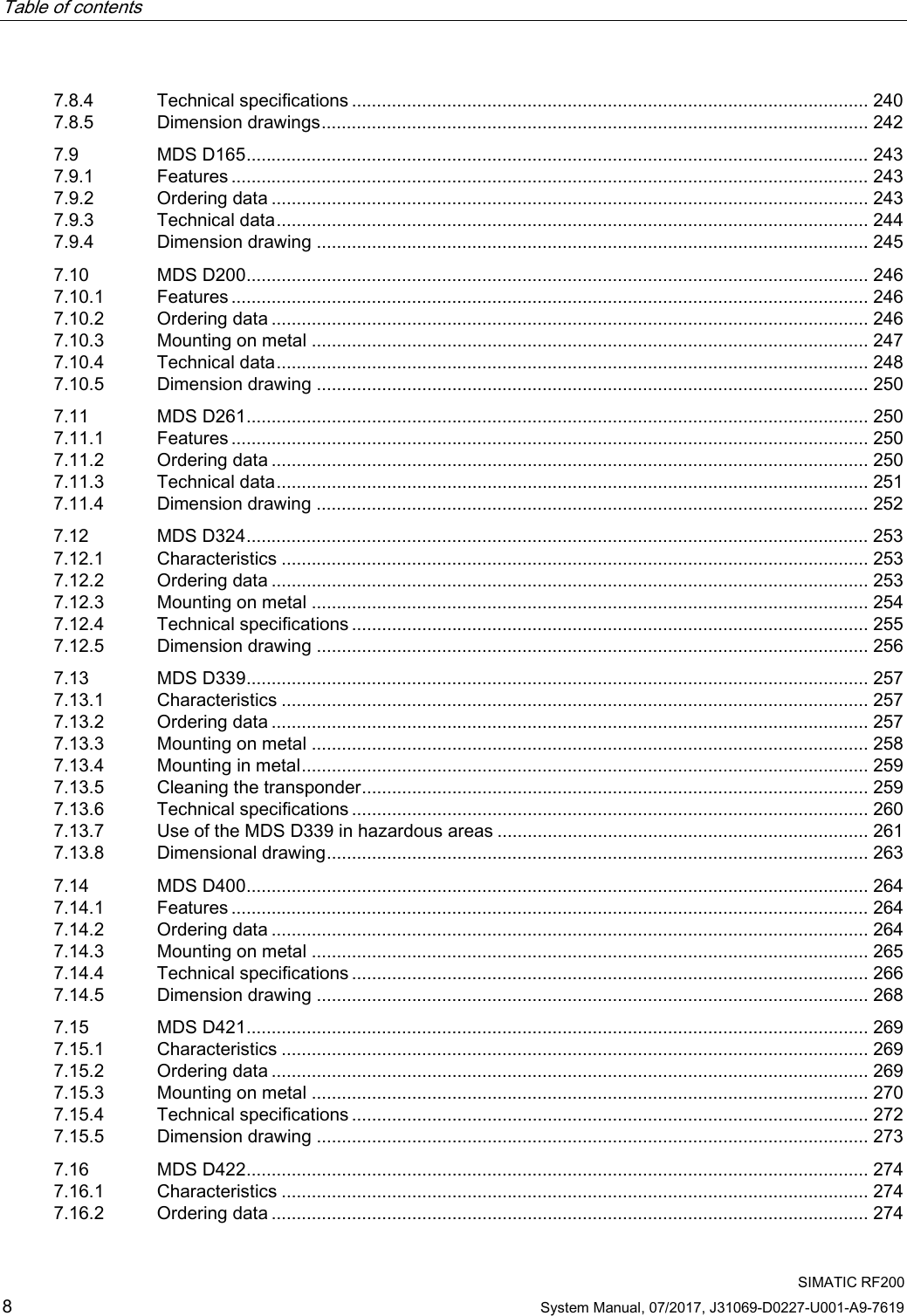
![Planning the RF200 system 4.3 Installation guidelines SIMATIC RF200 90 System Manual, 07/2017, J31069-D0227-U001-A9-7619 Polyamide 6 and Polyamide 6.6 GF30 Table 4- 36 Chemical resistance - PA6 and PA6.6 GF30 Substance Test conditions Rating Concentration [%] Temperature [°C] Mineral lubricants - - ++++ Aliphatic hydrocarbons - - ++++ Aromatic hydrocarbons - - ++++ Gasoline - - ++++ Weak mineral acids - - +++ Strong mineral acids - - ○ Weak organic acids - - ++ Strong organic acids - - ○ Oxidizing acids - - ○ Weak alkaline solutions - - ++ Strong alkaline solutions - - ○ Trichloroethylene - - ++++ Perchloroethylene - - ++++ Acetone - - ++++ Alcohols - - ++++ Hot water (hydrolysis resistance) - - ++ Explanation of the rating ++++ Resistant +++ Practically resistant ++ Conditionally resistant + Less resistant ○ Not resistant](https://usermanual.wiki/Siemens/RF280R.SYH-RF200-76-Part-1/User-Guide-3592552-Page-90.png)
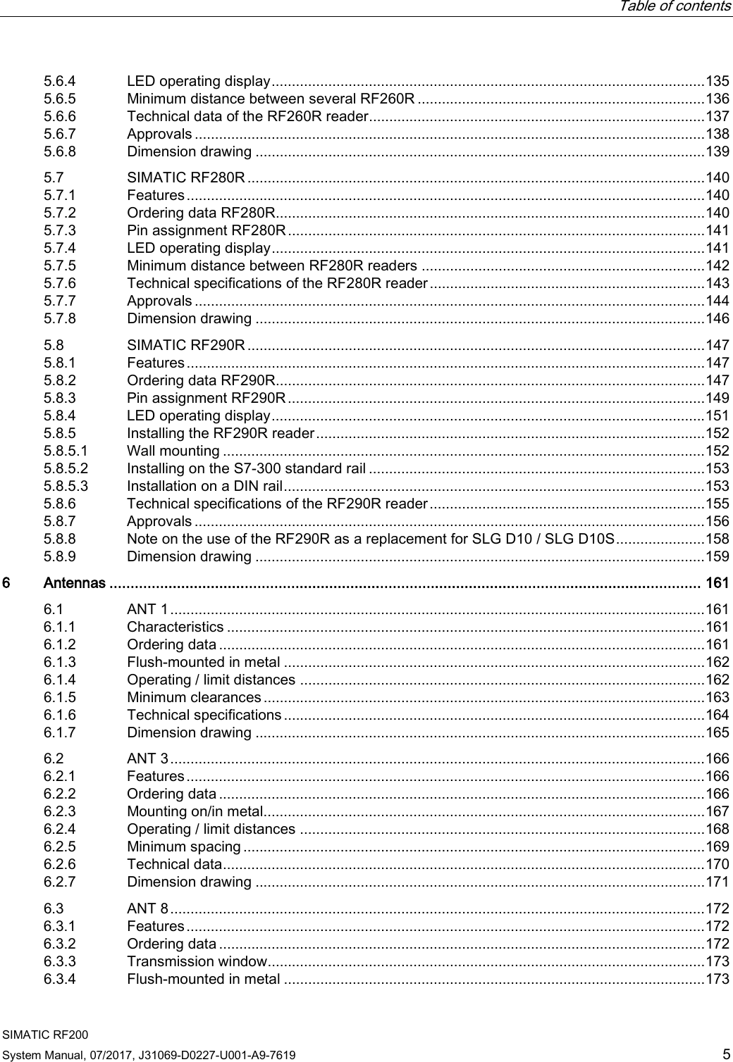
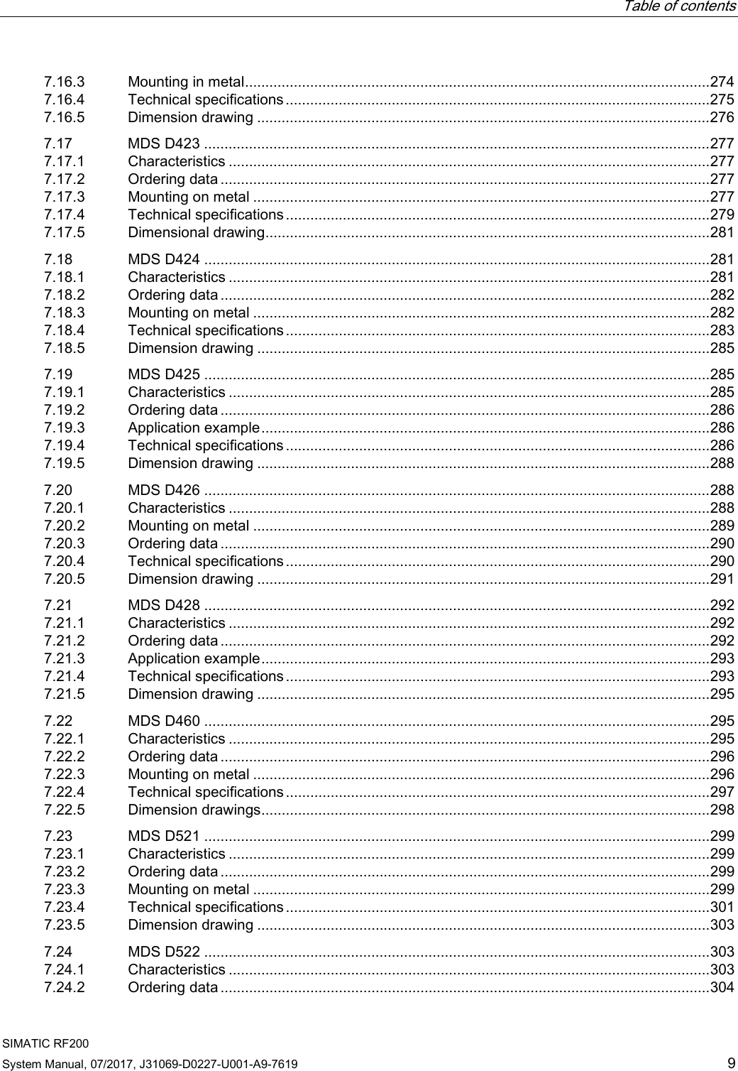
![Planning the RF200 system 4.3 Installation guidelines SIMATIC RF200 System Manual, 07/2017, J31069-D0227-U001-A9-7619 91 Polyamide 12 The resistance of the plastic housing to chemicals used in the automobile sector (e.g.: oils, greases, diesel fuel, gasoline, etc,) is not listed extra. Table 4- 37 Chemical resistance - Polyamide 12 Substance Test conditions Rating Concentration [%] Temperature [°C] Battery acid 30% 20 ℃ ++ Ammonia, gaseous - 60 ℃ ++++ Ammonia, w. conc. 60 ℃ ++++ 10% 60 ℃ ++++ Benzene - 20 ℃ ++++ - 60 ℃ +++ Bleach solution (12.5% effective chlo-rine) - 20 ℃ ++ Butane, gas, liquid - 60 ℃ ++++ Butyl acetate (acetic acid butyl ester) - 60 ℃ ++++ n(n) - 20 ℃ ++++ - 60 ℃ +++ Calcium chloride, w. - 20 ℃ ++++ - 60 ℃ +++ Calcium nitrate, w. c. s. 20 ℃ ++++ c. s. 60 ℃ +++ Chlorine - 20 ℃ ○ Chrome baths, tech. - 20 ℃ ○ Iron salts, w. c. s. 60 ℃ ++++ Acetic acid, w. 50% 20 ℃ ○ Ethyl alcohol, w., undenaturated 95% 20 ℃ ++++ 95% 60 ℃ +++ 50% 60 ℃ ++++ Formaldehyde, w. 30% 20 ℃ +++ 10% 20 ℃ ++++ 10% 60 ℃ +++ Formalin - 20 ℃ +++ Glycerine - 60 ℃ ++++ Isopropyl alcohol - 20 ℃ ++++ - 60 ℃ +++ Potassium hydroxide, w. 50% 60 ℃ ++++ Lysol - 20 ℃ ++ Magnesium salts, w. c. s. 60 ℃ ++++ Methyl alcohol, w. 50% 60 ℃ ++++ Lactic acid, w. 50% 20 ℃ ++ 10% 20 ℃ +++](https://usermanual.wiki/Siemens/RF280R.SYH-RF200-76-Part-1/User-Guide-3592552-Page-91.png)
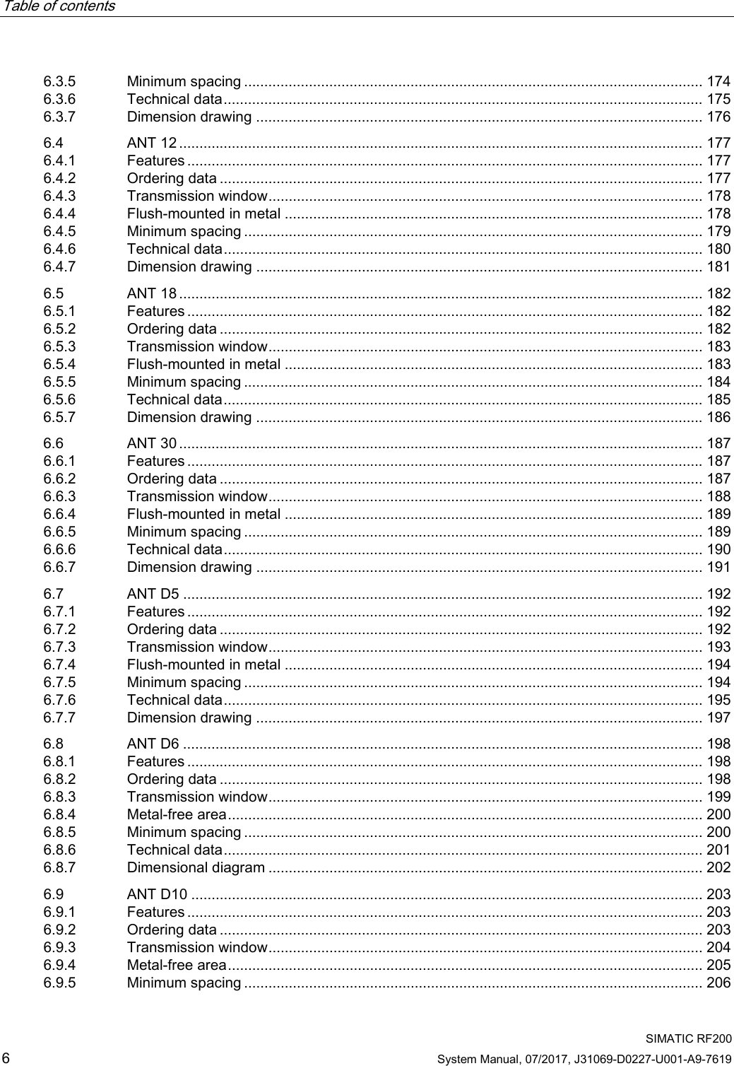
![Planning the RF200 system 4.3 Installation guidelines SIMATIC RF200 92 System Manual, 07/2017, J31069-D0227-U001-A9-7619 Substance Test conditions Rating Concentration [%] Temperature [°C] 10% 60 ℃ ++ Sodium carbonate, w. (soda) c. s. 60 ℃ ++++ Sodium chloride, w. c. s. 60 ℃ ++++ Sodium hydroxide - 60 ℃ ++++ Nickel salts, w. c. s. 60 ℃ ++++ Nitrobenzene - 20 ℃ +++ - 60 ℃ ++ Phosphoric acid 10% 20 ℃ + Propane - 60 ℃ ++++ Mercury - 60 ℃ ++++ Nitric acid 10% 20 ℃ + Hydrochloric acid 10% 20 ℃ + Sulfur dioxide low 60 ℃ ++++ Sulfuric acid 25% 20 ℃ ++ 10% 20 ℃ +++ Hydrogen sulfide low 60 ℃ ++++ Carbon tetrachloride - 60 ℃ ++++ Toluene - 20 ℃ ++++ - 60 ℃ +++ Detergent high 60 ℃ ++++ Plasticizer - 60 ℃ ++++ Explanation of the rating ++++ Resistant +++ Practically resistant ++ Conditionally resistant + Less resistant ○ Not resistant w. Water solution c. s. Cold saturated](https://usermanual.wiki/Siemens/RF280R.SYH-RF200-76-Part-1/User-Guide-3592552-Page-92.png)
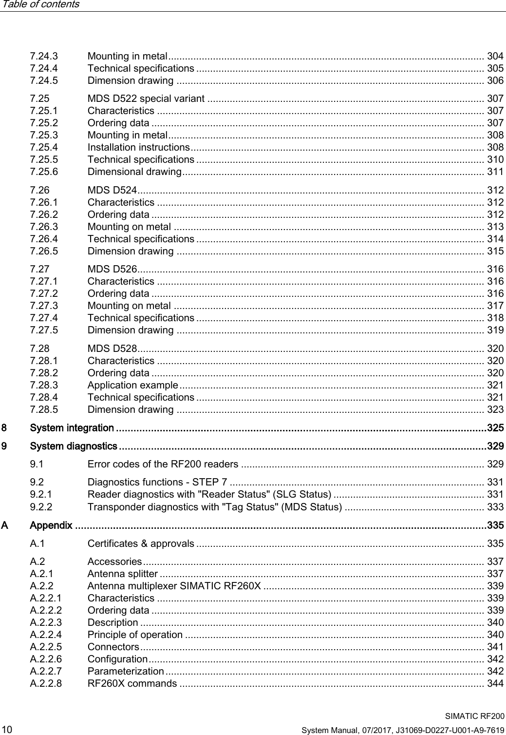
![Planning the RF200 system 4.3 Installation guidelines SIMATIC RF200 94 System Manual, 07/2017, J31069-D0227-U001-A9-7619 Note Chemical substances not listed The following sections describe the resistance of the various transponders to specific substances. If you require information about chemical substances that are not listed, contact Customer Support. Polyphenylene sulfide (PPS) The data memory has special chemical resistance to solutions up to a temperature of 200 °C. A reduction in the mechanical properties has been observed in aqueous solutions of hydrochloric acid (HCl) and nitric acid (HNO3) at 80 °C. The plastic housings are resistant to all types of fuel including methanol. Table 4- 39 Chemical resistance - polyphenylene sulfide (PPS) Substance Test conditions Rating Concentration [%] Temperature [°C] Acetone - 55 ℃ ++++ n-Butanol (butyl alcohol) - 80 ℃ ++++ Butanone-2 (methyl ethyl ketone) - 60 ℃ ++++ n-Butyl acetate - 80 ℃ ++++ Brake fluid - 80 ℃ ++++ Calcium chloride (saturated) - 80 ℃ ++++ Diesel fuel - 80 ℃ ++++ Diethyl ether - 23 ℃ ++++ Frigen 113 - 23 ℃ ++++ Anti-freeze - 120 ℃ ++++ Kerosene - 60 ℃ ++++ Methanol - 60 ℃ ++++ Engine oil - 80 ℃ ++++ Sodium chloride (saturated) - 80 ℃ ++++ Sodium hydroxide 30% 80 ℃ ++++ Sodium hypochlorite (30 or 180 days) 5% 80 ℃ ++ 5% 80 ℃ - Sodium hydroxide solution 30% 90 ℃ ++++ Nitric acid 10% 23 ℃ ++++ Hydrochloric acid 10% 80 ℃ - Sulfuric acid 10% 23 ℃ ++++ 10% 80 ℃ ++ 30% 23 ℃ ++++ Tested fuels - 80 ℃ ++++](https://usermanual.wiki/Siemens/RF280R.SYH-RF200-76-Part-1/User-Guide-3592552-Page-94.png)
![Planning the RF200 system 4.3 Installation guidelines SIMATIC RF200 System Manual, 07/2017, J31069-D0227-U001-A9-7619 95 Substance Test conditions Rating Concentration [%] Temperature [°C] FAM testing fluid acc. to DIN 51 604-A Toluene - 80 ℃ ++ 1, 1, 1-Trichloroethane Xylene - 80 ℃ ++++ Zinc chloride (saturated) - 80 ℃ ++ - 75 ℃ ++++ Explanation of the rating ++++ Resistant +++ Practically resistant ++ Conditionally resistant + Less resistant ○ Not resistant](https://usermanual.wiki/Siemens/RF280R.SYH-RF200-76-Part-1/User-Guide-3592552-Page-95.png)
![Planning the RF200 system 4.3 Installation guidelines SIMATIC RF200 96 System Manual, 07/2017, J31069-D0227-U001-A9-7619 Polycarbonate (PC) Table 4- 40 Chemical resistance - polycarbonate (PPS) Substance Test conditions Rating Concentration [%] Temperature [°C] Mineral lubricants - - ++ Aliphatic hydrocarbons - - ++++ Aromatic hydrocarbons - - ○ Gasoline - - ○ Weak mineral acids - - ++++ Strong mineral acids - - ++ Weak organic acids - - ++++ Strong organic acids - - ++ Oxidizing acids - - ○ Weak alkaline solutions - - ○ Strong alkaline solutions - - ○ Trichloroethylene - - ○ Perchloroethylene - - ○ Acetone - - ○ Alcohols - - ++ Hot water (hydrolysis resistance) - - ○ Explanation of the rating ++++ Resistant +++ Practically resistant ++ Conditionally resistant + Less resistant ○ Not resistant](https://usermanual.wiki/Siemens/RF280R.SYH-RF200-76-Part-1/User-Guide-3592552-Page-96.png)
![Planning the RF200 system 4.3 Installation guidelines SIMATIC RF200 System Manual, 07/2017, J31069-D0227-U001-A9-7619 97 Polyvinyl chloride (PVC) Table 4- 41 Chemical resistance - polyvinyl chloride (PVC) Substance Test conditions Rating Concentration [%] Temperature [°C] Salt water 5% - ++++ Sugared water 10% - ++++ Acetic acid, w. 5% - ++++ Sodium carbonate, w. 5% - ++++ Ethyl alcohol, w. 60% - ++++ Ethylene glycol 50% - ++++ Fuel B (acc. to ISO 1817) - - ++++ Human sweat - - ++++ Explanation of the rating ++++ Resistant ++++ Practically resistant ++ Conditionally resistant + Less resistant ○ Not resistant Epoxy resin Table 4- 42 Chemical Resistance - epoxy resin Substance Test conditions Rating Concentration [%] Temperature [°C] Allyl chloride - 20 ℃ ++++ Formic acid 50% 20 ℃ ++++ 100% 20 ℃ ++ Ammonia, gaseous - 20 ℃ ++++ Ammonia, liquid, water-free - 20 ℃ ○ Ammonium hydroxide 10% 20 ℃ ++++ Ethanol - 40 ℃ ++++ - 60 ℃ ++++ Ethyl acrylate - 20 ℃ ++++ Ethyl glycol - 60 ℃ ++++ Gasoline, aroma-free - 20 ℃ ++++ Gasoline, containing benzene - 20 ℃ ++++ Benzoates (Na–, Ca– among others) - 40 ℃ ++++ Benzoic acid - 20 ℃ ++++](https://usermanual.wiki/Siemens/RF280R.SYH-RF200-76-Part-1/User-Guide-3592552-Page-97.png)
![Planning the RF200 system 4.3 Installation guidelines SIMATIC RF200 98 System Manual, 07/2017, J31069-D0227-U001-A9-7619 Substance Test conditions Rating Concentration [%] Temperature [°C] Benzene - 20 ℃ ++++ Borax - 60 ℃ ++++ Boric acid - 20 ℃ ++++ Bromine, liquid - 20 ℃ ○ Bromides (K–, Na– among others) - 60 ℃ ++++ Bromoform 100% 20 ℃ ++++ Bromine water - 20 ℃ ○ Butadien (1.3–) - 20 ℃ ++++ Butane, gaseous - 20 ℃ ++++ Butanol - 20 ℃ ○ Butyric acid 100% 20 ℃ ++ Carbonates (ammonium–, Na– among others) - 60 ℃ ++++ Chlorine, liquid - 20 ℃ ○ Chlorine, gaseous, dry 100% 20 ℃ ○ Chlorobenzene - 20 ℃ ++++ Chlorides (ammonium–, Na– among others) - 60 ℃ ++++ Chloroform - 20 ℃ ○ Chlorophyll - 20 ℃ ++++ Chlorosulfuric acid 100% 20 ℃ ○ Chlorine water (saturated solution) - 20 ℃ ++ Chromates (K–, Na– among others) Up to 50 % 40 ℃ ++++ Chromic acid Up to 30 % 20 ℃ ○ Chromosulfuric acid - 20 ℃ ○ Citric acid - 20 ℃ ++++ Cyanamide - 20 ℃ ++++ Cyanides (K–, Na– among others) - 60 ℃ ++++ Dextrin, w. - 60 ℃ ++++ Diethyl ether - 20 ℃ ++++ Diethylene glycol - 60 ℃ ++++ Dimethyl ether - 20 ℃ ++++ Dioxane - 20 ℃ ○ Developer - 40 ℃ ++++ Acetic acid 100% 20 ℃ ++ Ethanol - 60 ℃ ++++ Fixing bath - 40 ℃ ++++ Fluorides (ammonium–, K–, Na– among others) - 40 ℃ ++++ Hydrofluoric acid Up to 40 % 20 ℃ ++++ Formaldehyde 50% 20 ℃ ++++ Formamide 100% 20 ℃ ++++](https://usermanual.wiki/Siemens/RF280R.SYH-RF200-76-Part-1/User-Guide-3592552-Page-98.png)
![Planning the RF200 system 4.3 Installation guidelines SIMATIC RF200 System Manual, 07/2017, J31069-D0227-U001-A9-7619 99 Substance Test conditions Rating Concentration [%] Temperature [°C] Gluconic acid - 20 ℃ ++++ Glycerine - 60 ℃ ++++ Glycol - 60 ℃ ++++ Urine - 20 ℃ ++++ Uric acid - 20 ℃ ++++ Hydroxides (ammonium...) 10% 20 ℃ ++++ Hydroxides (Na–, K–) 40% 20 ℃ ++++ Hydroxides (alkaline earth metal) - 60 ℃ ++++ Hypochlorites (K–, Na– among others) - 60 ℃ ++++ Iodides (K–, Na– among others) - 60 ℃ ++++ Silicic acid - 60 ℃ ++++ Cresol Up to 90 % 20 ℃ ○ Methanol 100% 40 ℃ ++++ Methylene chloride - 20 ℃ ○ Lactic acid 100% 20 ℃ ++ Mineral oils - 40 ℃ ++++ Nitrates (ammonium..., K– among others) - 60 ℃ ++++ Nitroglycerin - 20 ℃ ○ Oxalic acid - 20 ℃ ++++ Phenol 1% 20 ℃ ++++ Phosphates (ammonium..., Na– among others) 60 ℃ ++++ Phosphoric acid 50% 60 ℃ ++++ 85% 20 ℃ ++++ Propanol - 20 ℃ ++++ Nitric acid 25% 20 ℃ ○ Hydrochloric acid 10% 20 ℃ ○ Brine - 60 ℃ ○ Sulfur dioxide 100% 20 ℃ ++ Carbon disulfide 100% 20 ℃ ○ Sulfuric acid 40% 20 ℃ ○ Sulfurous acid - 20 ℃ ++ Soap solution - 60 ℃ ++++ Sulphates (ammonium..., Na– among others) - 60 ℃ ++++ Sulfites (ammonium..., Na– among others) - 60 ℃ ○ Tar, aroma-free - 60 ℃ ++++ Turpentine - 20 ℃ ++++ Trichloroethylene - 20 ℃ ○](https://usermanual.wiki/Siemens/RF280R.SYH-RF200-76-Part-1/User-Guide-3592552-Page-99.png)
![Planning the RF200 system 4.3 Installation guidelines SIMATIC RF200 100 System Manual, 07/2017, J31069-D0227-U001-A9-7619 Substance Test conditions Rating Concentration [%] Temperature [°C] Hydrogen peroxide 30% 20 ℃ ++++ Tartaric acid - 20 ℃ ++++ Explanation of the rating ++++ Resistant +++ Practically resistant ++ Conditionally resistant + Less resistant ○ Not resistant Polyamide 6 and Polyamide 6.6 GF30 Table 4- 43 Chemical resistance - PA6 and PA6.6 GF30 Substance Test conditions Rating Concentration [%] Temperature [°C] Mineral lubricants - - ++++ Aliphatic hydrocarbons - - ++++ Aromatic hydrocarbons - - ++++ Gasoline - - ++++ Weak mineral acids - - +++ Strong mineral acids - - ○ Weak organic acids - - ++ Strong organic acids - - ○ Oxidizing acids - - ○ Weak alkaline solutions - - ++ Strong alkaline solutions - - ○ Trichloroethylene - - ++++ Perchloroethylene - - ++++ Acetone - - ++++ Alcohols - - ++++ Hot water (hydrolysis resistance) - - ++ Explanation of the rating ++++ Resistant +++ Practically resistant ++ Conditionally resistant + Less resistant ○ Not resistant](https://usermanual.wiki/Siemens/RF280R.SYH-RF200-76-Part-1/User-Guide-3592552-Page-100.png)