Siemens RF280R RFID Reader 13.56 MHz User Manual SIMATIC RF200
Siemens AG RFID Reader 13.56 MHz SIMATIC RF200
UserManual.wiki
>
Siemens
>
RF280R User Manual
>
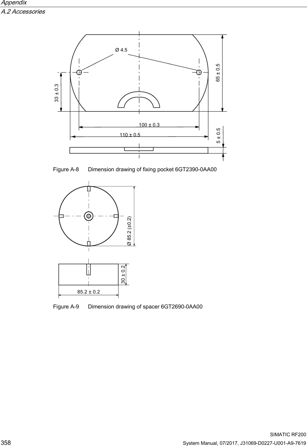
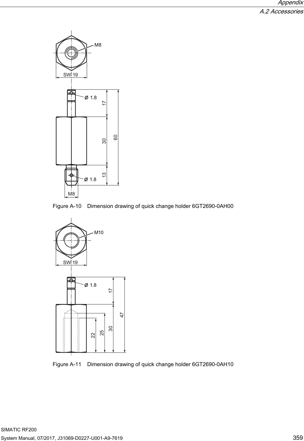
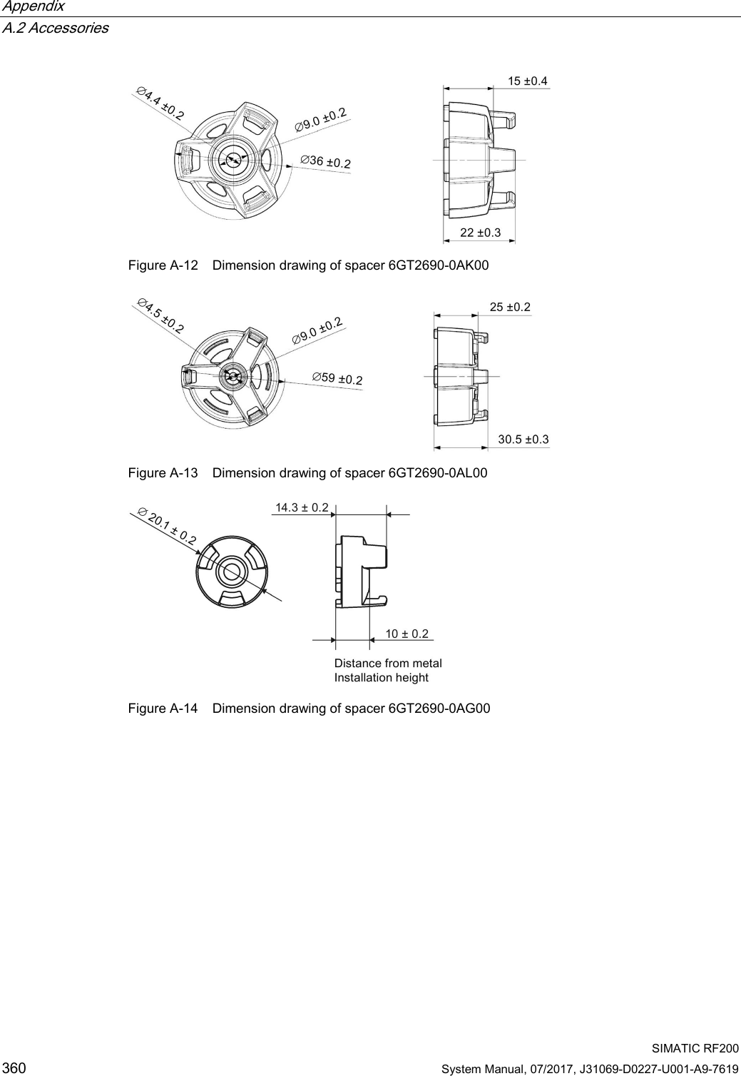
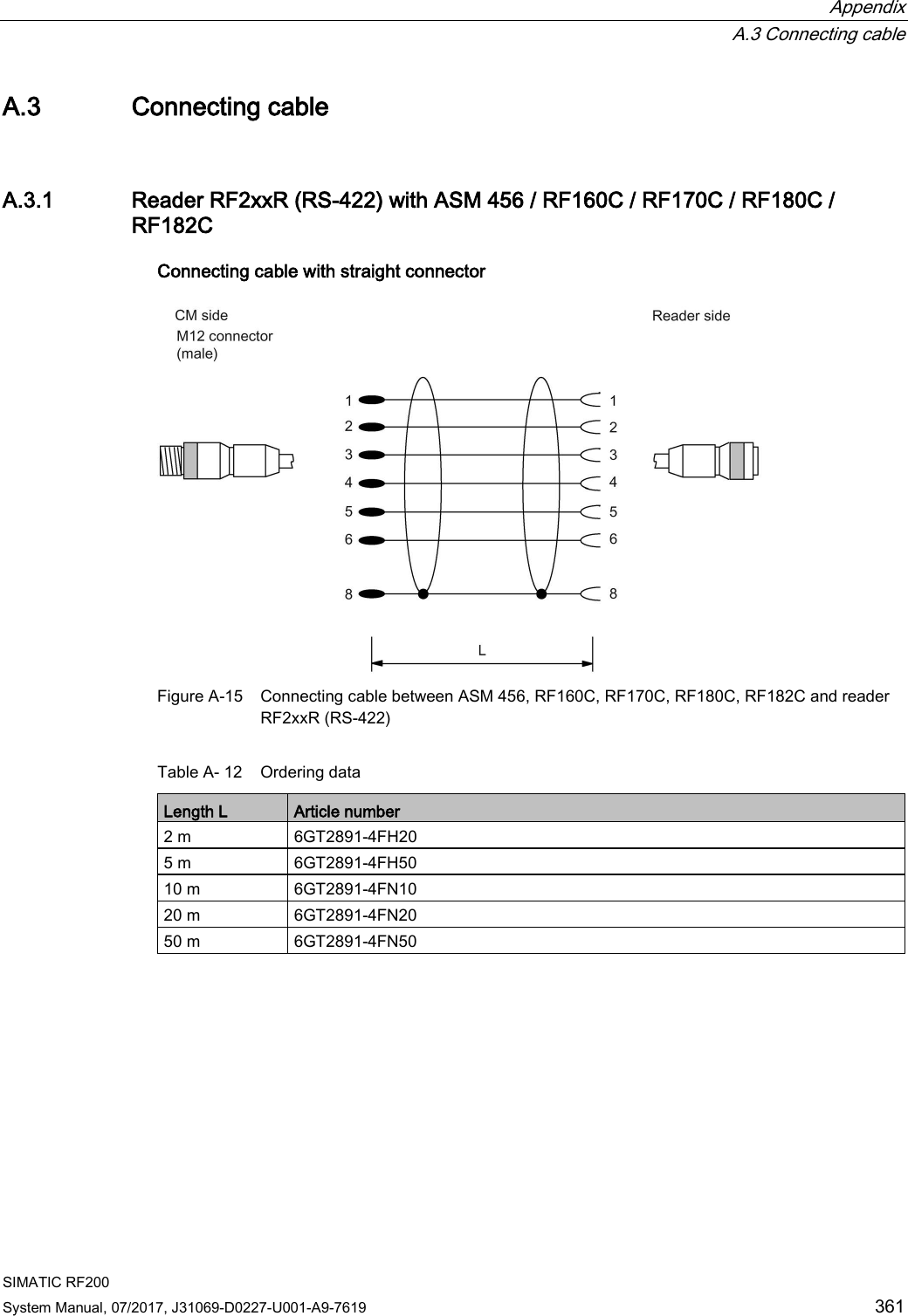
SYH_RF200_76_Part 3
Contents
1.
SYH_RF200_76_Part 1
2.
SYH_RF200_76_Part 2
3.
SYH_RF200_76_Part 3
SYH_RF200_76_Part 3
Navigation menu
Upload a User Manual
Namespaces
Wiki Guide
HTML
PDF
Info
Views
User Manual
Discussion / Help
Navigation

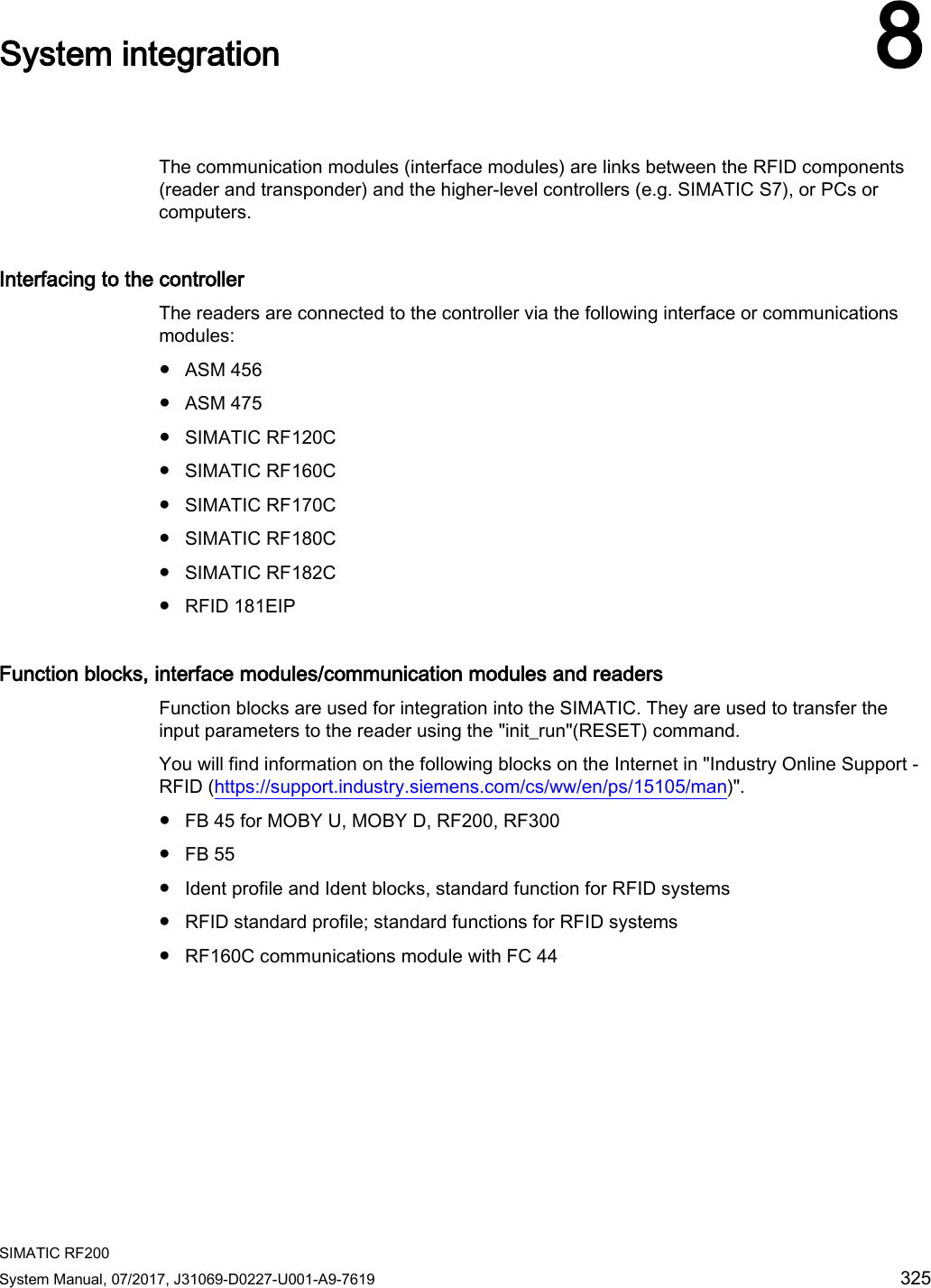
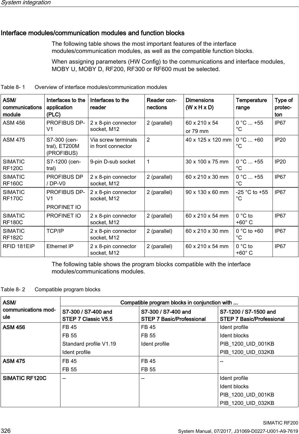
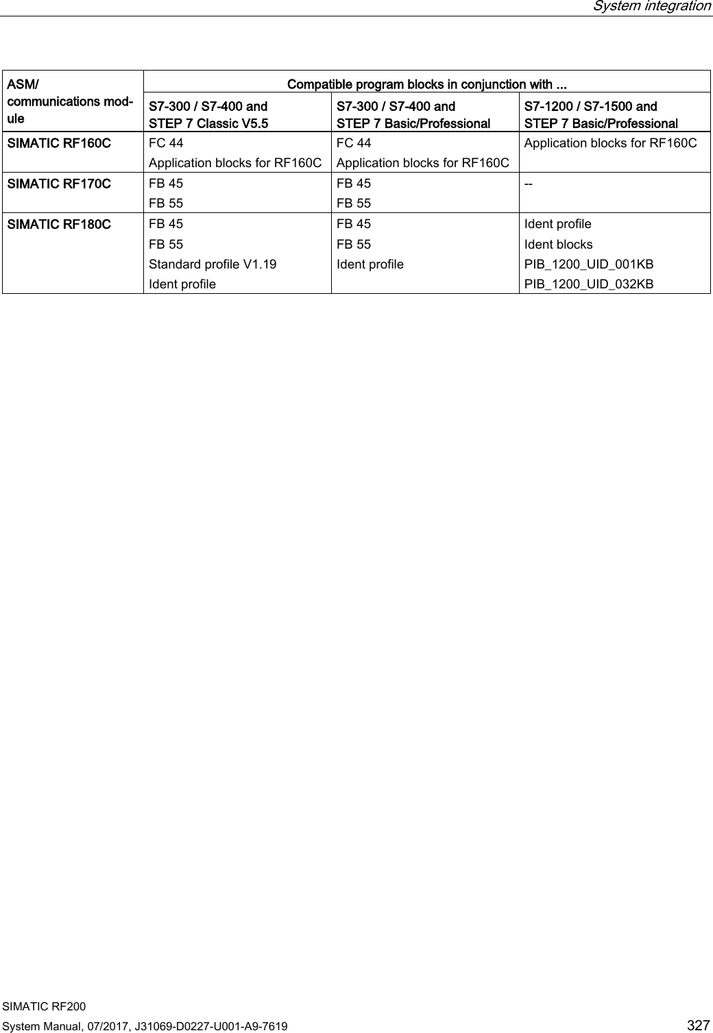

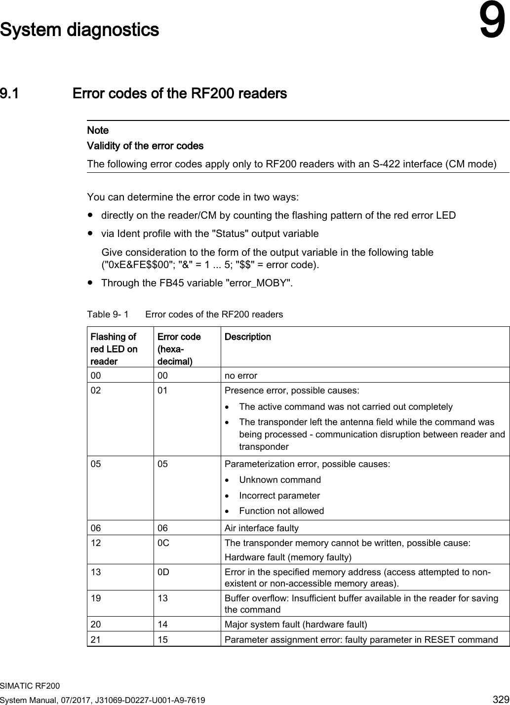
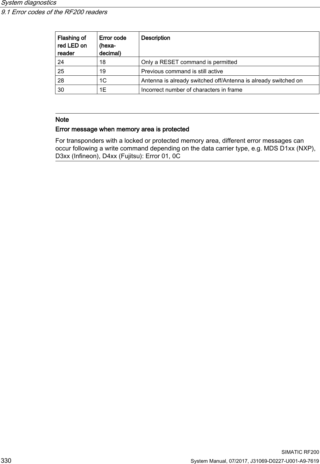
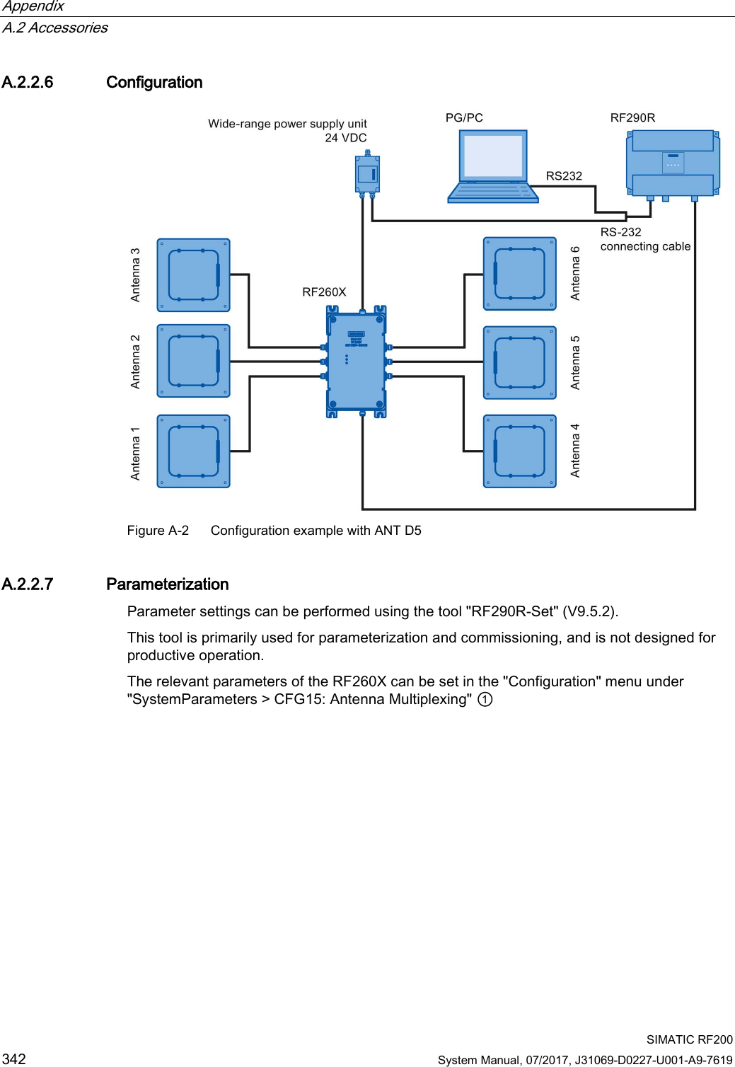
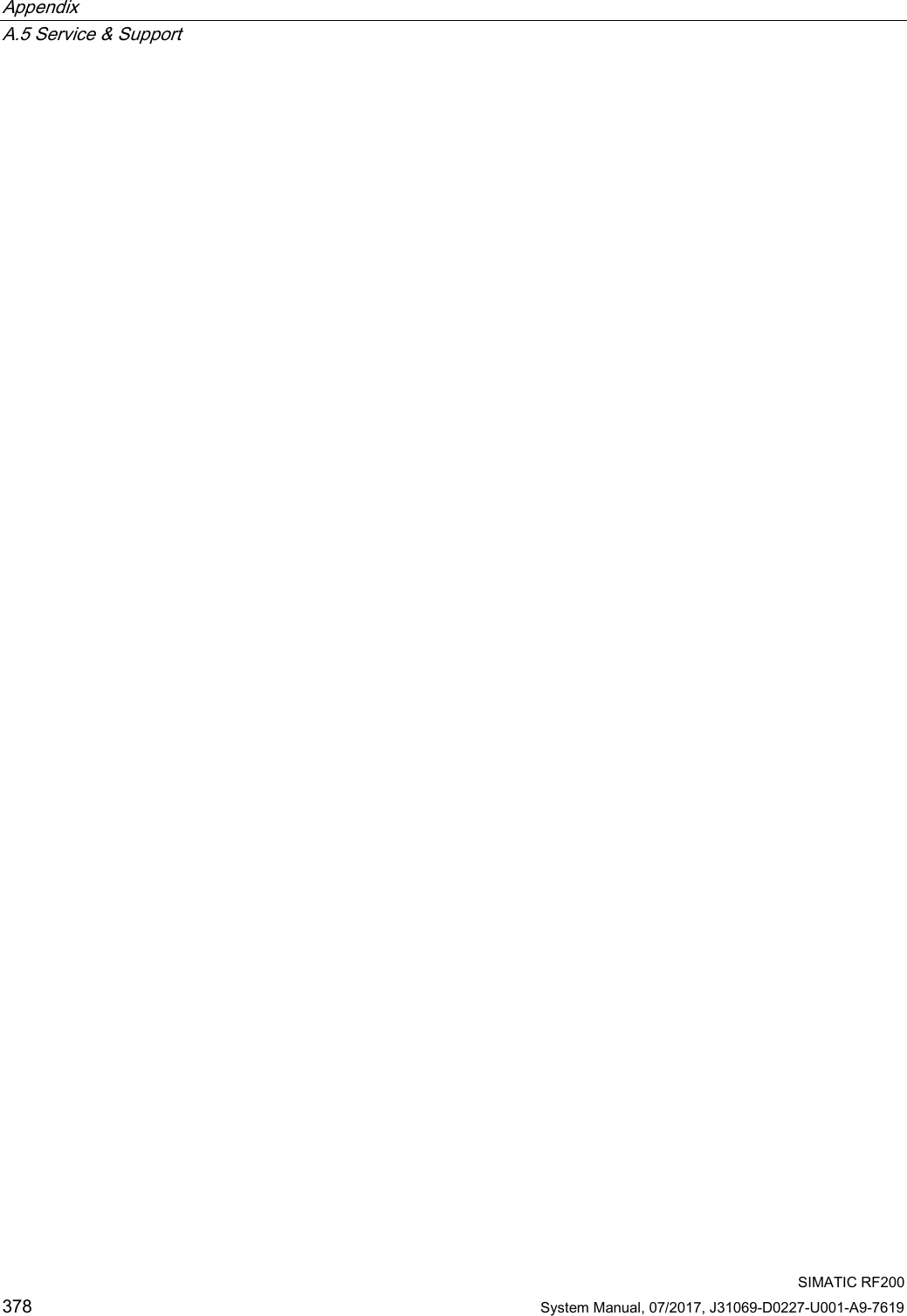
![System diagnostics 9.2 Diagnostics functions - STEP 7 SIMATIC RF200 System Manual, 07/2017, J31069-D0227-U001-A9-7619 333 9.2.2 Transponder diagnostics with "Tag Status" (MDS Status) The command can be used to scan the status data of the transponder that is located within the antenna field. Attribute "0x83" (mode 03), corresponds to UDT 230 Name Type Possible Values (hexadecimal) Comment UID array[1…8] byte 000000000 0000000 ... FFFFFFFF FFFFFFFF Unique identifier =8 byte UID, MSB first MDS_type byte -- Transponder type (chip vendor, designation): 01 = ISO 15693 general 03 = ISO 15693 (Infineon, MDS D3xx) 04 = ISO 15693 (Fujitsu - 2 KB, MDS D4xx); ISO 15693 (Fujitsu - 8 KB, MDS D5xx) 1) 05 = ISO 15693 (NXP, MDS D1xx) 06 = ISO 15693 (TI, MDS D2xx) 07 = ISO 15693 (STM, MDS D261) IC_version byte 0 ... FF Chip version size word 0 ... FF Memory size in bytes Depending on transponder type, e.g. MDS D3xx: 992 bytes lock_state byte 0 ... FF –not used with RF200 block_size byte 0 ... FF Block size of the transponder for each transponder type, e.g. MDS D3xx: 4 bytes nr_of_blocks byte 0 ... FF Number of blocks Depending on transponder type, e.g. MDS D3xx: 248 bytes 1) Except for RF280R; possible value (hexadecimal) 08](https://usermanual.wiki/Siemens/RF280R.SYH-RF200-76-Part-3/User-Guide-3592554-Page-11.png)