Siemens RF280R RFID Reader 13.56 MHz User Manual SIMATIC RF200
Siemens AG RFID Reader 13.56 MHz SIMATIC RF200
Siemens >
Contents
- 1. SYH_RF200_76_Part 1
- 2. SYH_RF200_76_Part 2
- 3. SYH_RF200_76_Part 3
SYH_RF200_76_Part 3
Antennas
6.3 ANT 8
SIMATIC RF200
System Manual, 07/2017, J31069-D0227-U001-A9-7619 173
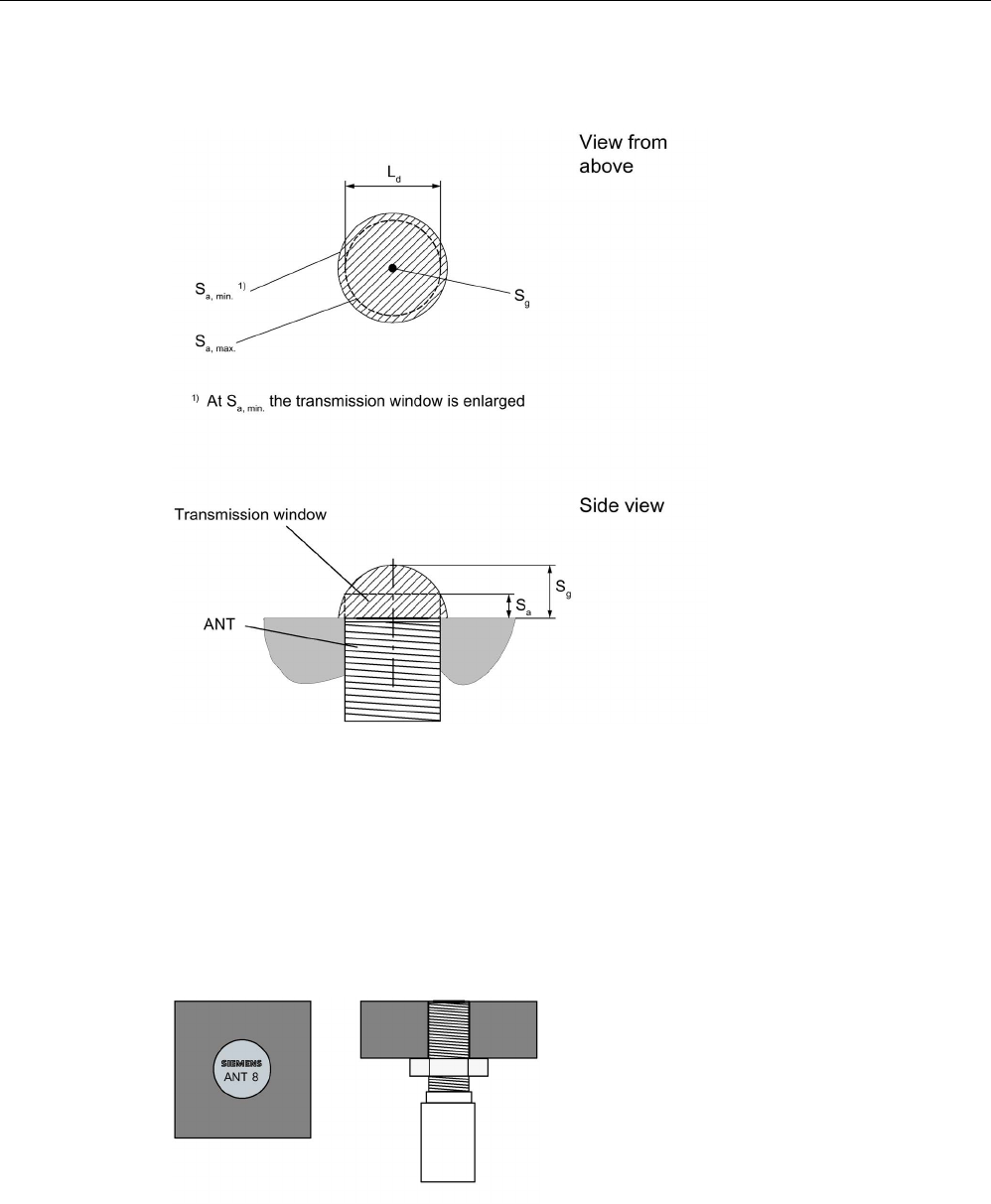
6.3.3
Transmission window
Ld
Length of the transmission window (= 3 mm)
Sa
Operating distance between antenna and transponder
Sg Limit distance (maximum clear distance between upper surface of the reader and the antenna,
at which the transmission can still function under normal conditions)
Figure 6-10 Transmission window ANT 8
6.3.4
Flush-mounted in metal
Figure 6-11 ANT 8 flush-mounted in metal

Transponder
7.28 MDS D528
SIMATIC RF200
324 System Manual, 07/2017, J31069-D0227-U001-A9-7619

SIMATIC RF200
System Manual, 07/2017, J31069-D0227-U001-A9-7619 325
System integration
8
The communication modules (interface modules) are links between the RFID components
(reader and transponder) and the higher-level controllers (e.g. SIMATIC S7), or PCs or
computers.
Interfacing to the controller
The readers are connected to the controller via the following interface or communications
modules:
● ASM 456
● ASM 475
● SIMATIC RF120C
● SIMATIC RF160C
● SIMATIC RF170C
● SIMATIC RF180C
● SIMATIC RF182C
● RFID 181EIP
Function blocks, interface modules/communication modules and readers
Function blocks are used for integration into the SIMATIC. They are used to transfer the
input parameters to the reader using the "init_run"(RESET) command.
You will find information on the following blocks on the Internet in "Industry Online Support -
RFID (https://support.industry.siemens.com/cs/ww/en/ps/15105/man)".
● FB 45 for MOBY U, MOBY D, RF200, RF300
● FB 55
● Ident profile and Ident blocks, standard function for RFID systems
● RFID standard profile; standard functions for RFID systems
● RF160C communications module with FC 44

System integration
SIMATIC RF200
326 System Manual, 07/2017, J31069-D0227-U001-A9-7619
Interface modules/communication modules and function blocks
The following table shows the most important features of the interface
modules/communication modules, as well as the compatible function blocks.
When assigning parameters (HW Config) to the communications and interface modules,
MOBY U, MOBY D, RF200, RF300 or RF600 must be selected.
Table 8- 1 Overview of interface modules/communication modules
ASM/
communications
module
Interfaces to the
application
(PLC)
Interfaces to the
reader
Reader con-
nections
Dimensions
(W x H x D)
Temperature
range
Type of
protec-
ton
ASM 456 PROFIBUS DP-
V1
2 x 8-pin connector
socket, M12
2 (parallel) 60 x 210 x 54
or 79 mm
0 °C ... +55
°C
IP67
ASM 475 S7-300 (cen-
tral), ET200M
(PROFIBUS)
Via screw terminals
in front connector
2 40 x 125 x 120 mm 0 °C ... +60
°C
IP20
SIMATIC
RF120C
S7-1200 (cen-
tral)
9-pin D-sub socket 1 30 x 100 x 75 mm 0 °C ... +55
°C
IP20
SIMATIC
RF160C
PROFIBUS DP
/ DP-V0
2 x 8-pin connector
socket, M12
2 (parallel) 60 x 210 x 30 mm 0 °C ... +55
°C
IP67
SIMATIC
RF170C
PROFIBUS DP-
V1
PROFINET IO
2 x 8-pin connector
socket, M12
2 (parallel) 90 x 130 x 60 mm -25 °C to +55
°C
IP67
SIMATIC
RF180C
PROFINET IO 2 x 8-pin connector
socket, M12
2 (parallel) 60 x 210 x 54 mm 0 °C to
+60° C
IP67
SIMATIC
RF182C
TCP/IP 2 x 8-pin connector
socket, M12
2 (parallel) 60 x 210 x 30 mm 0 °C to +60
°C
IP67
RFID 181EIP Ethernet IP 2 x 8-pin connector
socket, M12
2 (parallel) 60 x 210 x 54 mm 0 °C to
+60° C
IP67
The following table shows the program blocks compatible with the interface
modules/communications modules.
Table 8- 2 Compatible program blocks
ASM/
communications mod-
ule
Compatible program blocks in conjunction with ...
S7-300 / S7-400 and
STEP 7 Classic V5.5
S7-300 / S7-400 and
STEP 7 Basic/Professional
S7-1200 / S7-1500 and
STEP 7 Basic/Professional
ASM 456
FB 45
FB 55
Standard profile V1.19
Ident profile
FB 45
FB 55
Ident profile
Ident profile
Ident blocks
PIB_1200_UID_001KB
PIB_1200_UID_032KB
ASM 475
FB 45
FB 55
FB 45
FB 55
--
SIMATIC RF120C
-- -- Ident profile
Ident blocks
PIB_1200_UID_001KB
PIB_1200_UID_032KB

System integration
SIMATIC RF200
System Manual, 07/2017, J31069-D0227-U001-A9-7619 327
ASM/
communications mod-
ule
Compatible program blocks in conjunction with ...
S7-300 / S7-400 and
STEP 7 Classic V5.5
S7-300 / S7-400 and
STEP 7 Basic/Professional
S7-1200 / S7-1500 and
STEP 7 Basic/Professional
SIMATIC RF160C
FC 44
Application blocks for RF160C
FC 44
Application blocks for RF160C
Application blocks for RF160C
SIMATIC RF170C
FB 45
FB 55
FB 45
FB 55
--
SIMATIC RF180C
FB 45
FB 55
Standard profile V1.19
Ident profile
FB 45
FB 55
Ident profile
Ident profile
Ident blocks
PIB_1200_UID_001KB
PIB_1200_UID_032KB

System integration
SIMATIC RF200
328 System Manual, 07/2017, J31069-D0227-U001-A9-7619

SIMATIC RF200
System Manual, 07/2017, J31069-D0227-U001-A9-7619 329
System diagnostics
9
9.1
Error codes of the RF200 readers
Note
Validity of the error codes
The following error codes apply only to RF200 readers with an S
-422 interface (CM mode)
You can determine the error code in two ways:
● directly on the reader/CM by counting the flashing pattern of the red error LED
● via Ident profile with the "Status" output variable
Give consideration to the form of the output variable in the following table
("0xE&FE$$00"; "&" = 1 ... 5; "$$" = error code).
● Through the FB45 variable "error_MOBY".
Table 9- 1 Error codes of the RF200 readers
Flashing of
red LED on
reader
Error code
(hexa-
decimal)
Description
00
00
no error
02 01 Presence error, possible causes:
• The active command was not carried out completely
• The transponder left the antenna field while the command was
being processed - communication disruption between reader and
transponder
05 05 Parameterization error, possible causes:
• Unknown command
• Incorrect parameter
• Function not allowed
06
06
Air interface faulty
12 0C The transponder memory cannot be written, possible cause:
Hardware fault (memory faulty)
13 0D Error in the specified memory address (access attempted to non-
existent or non-accessible memory areas).
19 13 Buffer overflow: Insufficient buffer available in the reader for saving
the command
20
14
Major system fault (hardware fault)
21
15
Parameter assignment error: faulty parameter in RESET command

System diagnostics
9.1 Error codes of the RF200 readers
SIMATIC RF200
330 System Manual, 07/2017, J31069-D0227-U001-A9-7619
Flashing of
red LED on
reader
Error code
(hexa-
decimal)
Description
24
18
Only a RESET command is permitted
25 19 Previous command is still active
28
1C
Antenna is already switched off/Antenna is already switched on
30
1E
Incorrect number of characters in frame
Note
Error message when memory area is protected
For transponders with a locked or protected memory area, different error messages can
oc
cur following a write command depending on the data carrier type, e.g. MDS D1xx (NXP),
D3xx (Infineon), D4xx (Fujitsu): Error 01, 0C

System diagnostics
9.2 Diagnostics functions - STEP 7
SIMATIC RF200
System Manual, 07/2017, J31069-D0227-U001-A9-7619 331
9.2
Diagnostics functions - STEP 7
Further information on RFID diagnostics options can be found in the following function
manuals:
● Function manual Ident profile and Ident blocks
(https://support.industry.siemens.com/cs/us/en/view/106368029)
● Function Manual FB 45 (https://support.industry.siemens.com/cs/ww/en/view/21738808)
9.2.1
Reader diagnostics with "Reader Status" (SLG Status)
With this command you can query the status and diagnostics data of the reader.
Attribute "0x81" (mode 01), corresponds to UDT 110
Name
Type
Possible Values
(hexadecimal)
Comment
hardware char
4D
4E
31
32
33
34
41
Type of hardware
= RF280R with RS232
= RF280R with RS422
= RF260R
= RF210/220R
= RF240R
= RF250R
= RF290R
hardware_version word
01 00
00 10; 00 29; 00 2B; 00
2C
HW version (reserved)
= RF200 without RF280R
= RF280R
loader_version word
00 ... FF
00 ... FF
Bootstrap loader version: e.g. 3130 (=version 1.0)
= Version (high byte)
= Version (low byte)
firmware
char
00 ... FF
FW version : 33 (ASCII : 3 = RF2x0R)
firmware_version word
00 ... FF
00 ... FF
Firmware version: e.g. 3130 (=version 1.0)
= Version (high byte)
= Version (low byte)
driver char
31
32
33
Driver version 3964R
= 3964R
= ASCII
= ASCII/ScanMode
driver_version word
00 ... FF
00 ... FF
Driver version: e.g. 3132 (=version 1.2)
= Version (high byte)
= Version (low byte)
interface byte
01
02
Interface type
= RS-422
= RS-232

System diagnostics
9.2 Diagnostics functions - STEP 7
SIMATIC RF200
332 System Manual, 07/2017, J31069-D0227-U001-A9-7619
Name
Type
Possible Values
(hexadecimal)
Comment
baud byte
01
03
05
Transmission speed
= 19.2 kBd
= 57.6 kBd
= 115.2 kBd
multitag_SLG byte
01
Number of transponders (multitag/bulk) that can be
processed in the antenna field
= Single tag mode
field_ON_time_SLG byte 01
ISO transponder (non-specific)
status_ant byte
01
02
Status of the antenna
= Antenna is on
= antenna is off
MDS_control byte
00
01
Presence check
= Operation without presence check
= Operation with presence check (antenna is acti-
vated.)
Note
Completeness of the table
Be aware that unassigned fields in the UDT are not listed here.

System diagnostics
9.2 Diagnostics functions - STEP 7
SIMATIC RF200
System Manual, 07/2017, J31069-D0227-U001-A9-7619 333
9.2.2
Transponder diagnostics with "Tag Status" (MDS Status)
The command can be used to scan the status data of the transponder that is located within
the antenna field.
Attribute "0x83" (mode 03), corresponds to UDT 230
Name
Type
Possible Values
(hexadecimal)
Comment
UID array[1…8] byte
000000000
0000000 ...
FFFFFFFF
FFFFFFFF
Unique identifier
=8 byte UID, MSB first
MDS_type byte
--
Transponder type (chip vendor, designation):
01
= ISO 15693 general
03
= ISO 15693 (Infineon, MDS D3xx)
04 = ISO 15693 (Fujitsu - 2 KB, MDS D4xx);
ISO 15693 (Fujitsu - 8 KB, MDS D5xx)
1)
05
= ISO 15693 (NXP, MDS D1xx)
06
= ISO 15693 (TI, MDS D2xx)
07
= ISO 15693 (STM, MDS D261)
IC_version
byte
0 ... FF
Chip version
size word 0 ... FF Memory size in bytes
Depending on transponder type, e.g. MDS D3xx: 992 bytes
lock_state
byte
0 ... FF
–not used with RF200
block_size byte 0 ... FF Block size of the transponder
for each transponder type, e.g. MDS D3xx: 4 bytes
nr_of_blocks byte 0 ... FF Number of blocks
Depending on transponder type, e.g. MDS D3xx: 248 bytes
1) Except for RF280R; possible value (hexadecimal) 08

System diagnostics
9.2 Diagnostics functions - STEP 7
SIMATIC RF200
334 System Manual, 07/2017, J31069-D0227-U001-A9-7619
SIMATIC RF200
System Manual, 07/2017, J31069-D0227-U001-A9-7619 335
Appendix
A
A.1
Certificates & approvals
All the latest RFID radio approvals are available on the Internet
(http://www.siemens.com/rfid-approvals).
Labeling
Description
Conformity acc. to the RED EU directive
Notes on CE marking
The following applies to the system described in this documentation:
The CE marking on a device indicates the corresponding approval:
DIN ISO 9001 certificate
The quality assurance system for the entire product process (development, production, and
marketing) at Siemens fulfills the requirements of ISO 9001 (corresponds to EN29001:
1987).
This has been certified by DQS (the German society for the certification of quality
management systems).
EQ-Net certificate no.: 1323-01
Country-specific approvals:
Safety
If the device has one of the following markings the corresponding approval has been
obtained:
Labeling
Description
Underwriters Laboratories (UL) per UL 60950 (I.T.E) or per UL 508
(IND.CONT.EQ)
Underwriters Laboratories (UL) according to Canadian standard C22.2
No. 60950 (I.T.E) or C22.2 No. 142 (IND.CONT.EQ)
Underwriters Laboratories (UL) according to standard UL 60950, Re-
port E11 5352 and Canadian standard C22.2 No. 60950 (I.T.E) or
UL508 and C22.2 No. 142 (IND.CONT.EQ)
UL recognition mark
Appendix
A.1 Certificates & approvals
SIMATIC RF200
336 System Manual, 07/2017, J31069-D0227-U001-A9-7619
Labeling
Description
Canadian Standard Association (CSA) acc. to standard C22.2. No.
60950 (LR 81690) or acc. to C22.2 No. 142 (LR 63533)
Canadian Standard Association (CSA) per American Standard UL
60950 (LR 81690) or per UL 508 (LR 63533)
This product meets the requirements of the AS/NZS 3548 Norm.
USA (FCC)
This device complies with Part 15 of the FCC Rules.
FCC ID: NXW-RF...
Canada (IC) Canada (IC)
This device complies with Industry Canada licence-exempt RSS
standard(s).
IC: 267X-RF...
Russia, Belarus and Kazakhstan
Brazil (ANATEL)
ANATEL-ID: XXXX-YY-ZZZZ)
Mexico (COFETEL)
Mexico (COFETEL)
South Africa (ICASA)
China (CMIIT) China (CMIIT)
CMIIT ID: XXXXYYZZZZ
South Korea (KCC)
Japan (VCCI)
Appendix
A.2 Accessories
SIMATIC RF200
System Manual, 07/2017, J31069-D0227-U001-A9-7619 337
A.2
Accessories
A.2.1
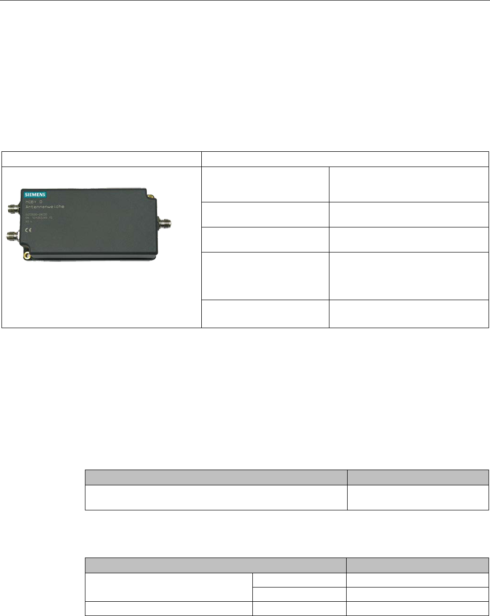
Antenna splitter
Area of application
Antenna splitter
Characteristics
Area of application Designed for distributed mounting of
antennas in warehouses, logistics and
distribution
Readers that can be connect-
ed
RF290R
Number of connectable
antennas
max. 4
(by cascading)
Connectable antennas • ANT D5
• ANT D6
• ANT D10
Degree of protection IP65
The antenna splitter is a power distributor with electrical isolation between the input (IN) and
the two outputs (OUT1, OUT2). At the operating frequency of 13.56 MHz, the impedance at
all inputs and outputs is 50 ohms.
The device is used to connect 2 to 4 antennas to a reader. Gate, C and tunnel arrangements
are therefore possible (see section "Configuration options").
Ordering data
Table A- 1 Ordering data for the antenna splitter
Article number
Antenna splitter
(incl. one antenna connecting cable 3.3 m)
6GT2690-0AC00
Table A- 2 Ordering data - accessories - antenna splitter
Article number
Antenna cable
Length 3.3 m
6GT2691-0CH33
Length 10.5 m
6GT2691-0CN10
Antenna cable extension
Length 7.2 m
6GT2691-0DH72

Appendix
A.2 Accessories
SIMATIC RF200
338 System Manual, 07/2017, J31069-D0227-U001-A9-7619
Technical specifications
Table A- 3 Technical specifications for antenna splitter
Technical specifications
max. Input power
10 W
Transmission frequency
13.56 MHz
Power supply
None
Housing dimensions (L x W x H) 160 x 80 x 40 mm
(without connector)
Color
Anthracite
Material
Plastic PA 12
Connector (inputs and outputs)
TNC connector
Securing
2 x M5 screws
Ambient temperature
• During operation
• During transportation and storage
• -25 ℃ ... +65 ℃
• -25 ℃ ... +75 ℃
MTBF
3.0 x 10
5
hours
Degree of protection according to EN 60529
IP65 (UL: for indoor use only)
Shock resistant according to EN 60721-3-7
Class 7M2
Total shock response spectrum Type II
30 g
Vibration according to EN 60721-3-7 Class 7M2 1 g (9 ... 200 Hz) /
1.5 g (200 ... 500 Hz)
Weight, approx.
400 g
Approval CE
UL
Appendix
A.2 Accessories
SIMATIC RF200
System Manual, 07/2017, J31069-D0227-U001-A9-7619 339
A.2.2
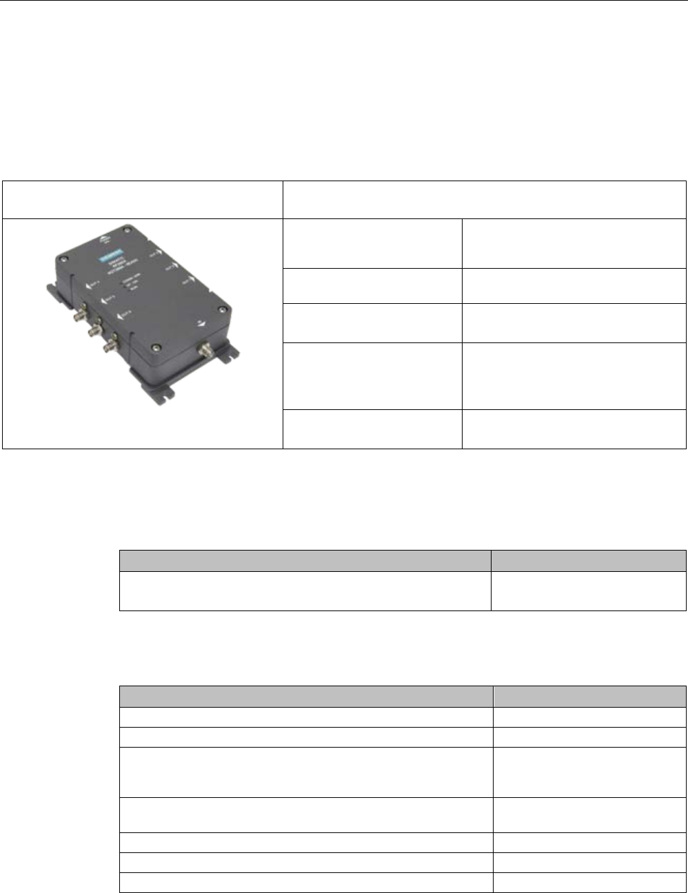
Antenna multiplexer SIMATIC RF260X
A.2.2.1
Characteristics
The SIMATIC RF260X antenna multiplexer can be used to operate up to six antennas on
one reader.
SIMATIC RF260X
antenna multiplexer
Characteristics
Area of application Designed for distributed mounting of
antennas in warehouses, logistics and
distribution
Readers that can be connect-
ed
RF290R
Number of antennas that can
be connected
maximum of 6
Connectable antennas • ANT D5
• ANT D6
• ANT D10
Degree of protection IP65
A.2.2.2
Ordering data
Table A- 4 SIMATIC RF260X ordering data
Article number
SIMATIC RF260X
Antenna multiplexer incl. antenna connecting cable 0.4 m
6GT2894-0EA00
Table A- 5 SIMATIC RF260X accessories ordering data
Article number
24 V connecting cable, 5 m
6GT2491-1HH50
RF290R
6GT2821-0AC12
Wide-range power supply unit for SIMATIC RF-systems
(100 - 240 V AC / 24 V DC / 3 A)
with 2 m connecting cable with country-specific plug
EU: 6GT2898-0AA00
UK: 6GT2898-0AA10
US: 6GT2898-0AA20
RS-232 connecting cable, with 4-pin M12 connector for 24 V for
connection to the wide-range power supply unit, 5 m
6GT2891-4KH50
ANT D5 incl. antenna connecting cable (3.3 m)
6GT2698-5AA10
ANT D6 incl. antenna connecting cable (3.3 m)
6GT2698-5AB00
ANT D10 incl. antenna connecting cable (3.3 m)
6GT2698-5AF00
Appendix
A.2 Accessories
SIMATIC RF200
340 System Manual, 07/2017, J31069-D0227-U001-A9-7619
Article number
Antenna cable
3.3 m
6GT2691-0CH33
10.5 m 6GT2691-0CN10
Antenna cable extension
7.2 m
6GT2691-0DH72
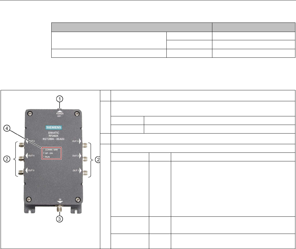
A.2.2.3
Description
①
24 V DC power supply
②
Antenna connections OUT 1 to OUT 6
with LEDs
Color Status LED
Yellow
Lit when the corresponding antenna output is active.
③
SLG antenna connection "IN"
③
LEDs
LED
Color
Status LED
COMM / ERR Red • Flashes when the RF260X receives a signal
from the SLG. (Only with commands directly to
the RF260X)
• Lit when the multiplexer has detected an error
on the output
(e.g. non-terminated antenna cable / defective
antenna cable / short-circuit)
HF - ON Green Lit when an HF signal is applied to the "IN" socket
③
RUN Green Flashes when the RF260X is in the normal operat-
ing state.
A.2.2.4
Principle of operation
You can operate up to six antennas on one reader by using the multiplexer RF260X. The
data is processed sequentially.
Antenna switchover is performed in time-multiplex mode, so by connecting several antennas
together, the processing time / activation time per antenna is lengthened accordingly.
Appendix
A.2 Accessories
SIMATIC RF200
System Manual, 07/2017, J31069-D0227-U001-A9-7619 341
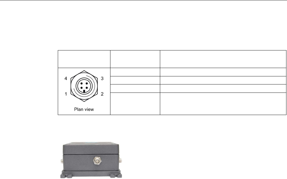
A.2.2.5
Connectors
●
Power supply
Pin
Pin, casing side
4-pin M12
Assignment
RF260X
1
Ground (0 V)
2
+ 24 V
3
+ 24 V
4 Ground (0 V)
●
Reader connector ③
Figure A-1 Reader connector
If a longer antenna cable is required between the RF290R and SIMATIC RF260X
multiplexer, a 7.2 m long cable (e.g. 6GT2691-0DH72) must be used to extend it, see
Ordering data (Page 339).
The excess length must then be rolled up bifilar and fastened to minimize interference
from external sources.
●
Antenna outputs ② (OUT 1 to OUT 3 / OUT 4 to OUT 6)
Appendix
A.2 Accessories
SIMATIC RF200
342 System Manual, 07/2017, J31069-D0227-U001-A9-7619
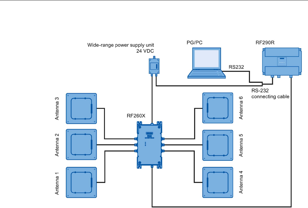
A.2.2.6
Configuration
Figure A-2 Configuration example with ANT D5
A.2.2.7
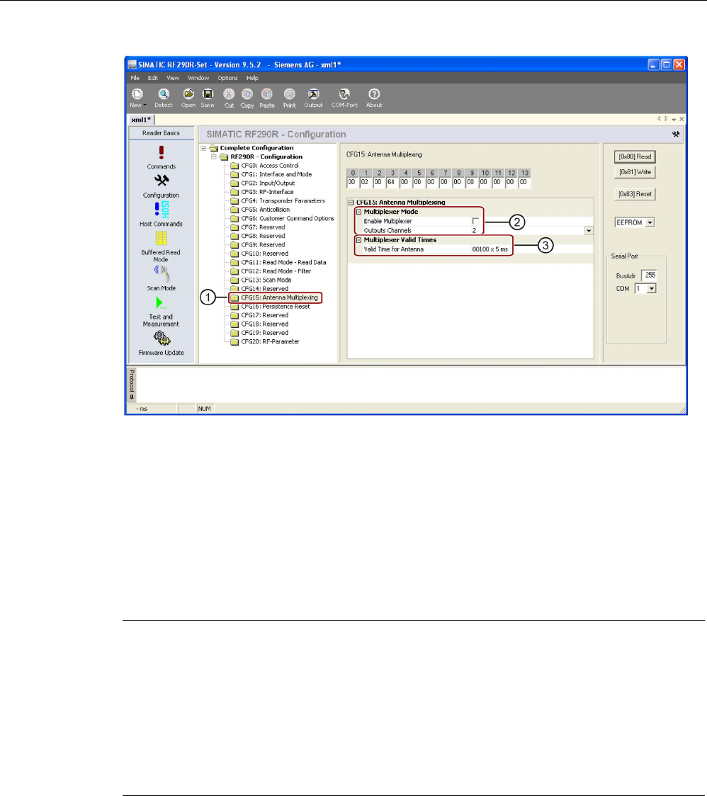
Parameterization
Parameter settings can be performed using the tool "RF290R-Set" (V9.5.2).
This tool is primarily used for parameterization and commissioning, and is not designed for
productive operation.
The relevant parameters of the RF260X can be set in the "Configuration" menu under
"SystemParameters > CFG15: Antenna Multiplexing" ①
Appendix
A.2 Accessories
SIMATIC RF200
System Manual, 07/2017, J31069-D0227-U001-A9-7619 343
Figure A-3 Menu "Configuration" MOBYDSet"
● For operation with RF260X, you need to activate the "Multiplexing" function ②.
● The number of occupied channels must be specified under "Number of Output Channels"
②.
● In "Multiplexer Valid Times" ③, the maximum time available for the antenna to read a
transponder is entered. Following this time, the device switches to the next antenna
automatically. If the read was successful, the time may be significantly shorter than
specified here.
Note
Changing the parameter assignment
•
Note that if you change the parameter settings of the reader or the RF260X in scanner
mode, this may lead to frame collisions. These collisions result when the frame is sent
while a transponder is present.
•
The "Transponder response time" (setting: "CFG2: COM interface") during operation of
the RF260X must be higher than the total delay time for all the connected antennas
(CFG15: MUX-VALD-TIME × Number of Output Channels ≤ Transponder Response
Time)
Appendix
A.2 Accessories
SIMATIC RF200
344 System Manual, 07/2017, J31069-D0227-U001-A9-7619
A.2.2.8
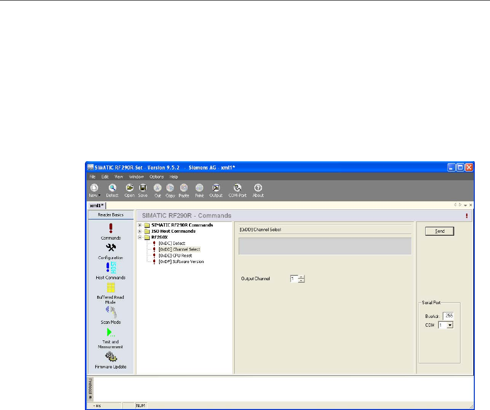
RF260X commands
Using the tool "RF290R-Set" (V9.5.2), certain commands can also be sent to the RF260X. In
the "Commands" menu under "RF260X", the following commands can be sent:
● Detect (detection of the RF260X by the reader)
● Channel Select (set to a static channel)
● CPU-Reset (restart the RF260X software)
● Software Version (read out software and hardware versions)
Figure A-4 Sending commands from the "RF290R-Set" tool

Appendix
A.2 Accessories
SIMATIC RF200
System Manual, 07/2017, J31069-D0227-U001-A9-7619 345
A.2.2.9
Technical specifications
Technical specifications
Max. write/read distance
ANT ↔ Transponder (S
g
)
See manual for the relevant antenna
Number of channels
• Input channels
• Output channels
• 1
• 6
Impedance
50 ohm
Power supply
24 V (± 10 %)
Current consumption
max. 200 mA
Dimensions (L x W x H)
240 x 150 x 70 mm
Length of the connecting cable
0.4 m
Color
Anthracite
Material
Aluminum die-casting
Plug-in connections • Power supply: Four-pole M12 / 4 pole round
connector
• Reader antenna connector: Single-pole TNC
socket
• Antenna connections: 6 x TNC socket
Max. power (reader input, or per antenna)
8 W
Shock resistant according to EN 60721-3-7
Class 7M2
Total shock response spectrum Type II
1.5 g
Vibration according to EN 60721-3-7 Class 7M2
1.5 g (5 to 500 Hz)
Securing
4 M5 screws
Tightening torque
(at room temperature)
≤ 5 Nm
Ambient temperature
• During operation
• During transportation and storage
• -20 ℃ ... +55 ℃
• -25 ℃ ... +70 ℃
MTBF
2.5 x 10
6
hours
Degree of protection according to EN 60529 IP65
Weight, approx. 1.8 kg
Approvals CE / FCC / IC
Appendix
A.2 Accessories
SIMATIC RF200
346 System Manual, 07/2017, J31069-D0227-U001-A9-7619
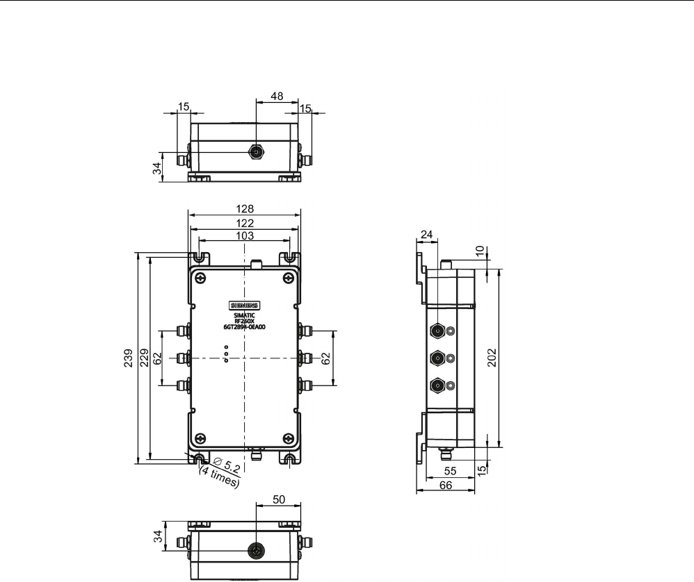
A.2.2.10
Dimensional drawing
Figure A-5 RF260X dimension drawing
Appendix
A.2 Accessories
SIMATIC RF200
System Manual, 07/2017, J31069-D0227-U001-A9-7619 347
A.2.3
Wide-range power supply unit for SIMATIC RF systems
A.2.3.1
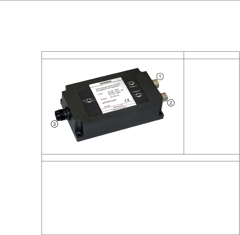
Features
Wide-range power supply unit for SIMATIC RF systems
① DC output 1
② DC output 2
③ Network connector
Characteristics
• Wide-range input
③
for use worldwide
• Dimensions without mains cable: 175 x 85 x 35 mm
• Dimensions including mains cable: 250 x 85 x 35 mm
• CE-compliant (EU and UK versions)
• UL-certified for US and Canada (US version)
• Mechanically and electrically rugged design
• Secondary side ①, ②: 24 VDC / 3 A
• Short-circuit and no-load stability
• Suitable for frame mounting
• 3 versions for use in the EU, UK, US
Description
The wide-range power supply unit for SIMATIC RF systems is a universal compact power
supply and provides the user with an efficient, cost-saving solution for many different mid-
range power supply tasks.
The primary switched power supply is designed for use on single-phase AC systems. The
two DC outputs (sockets) are connected in parallel and protected by a built-in current limiting
circuit against overload and short-circuits.
The device is vacuum-cast and prepared for Safety Class 2 applications. The EU and UK
versions satisfy the low-voltage guideline as well as the current EU standards for CE
conformity. Furthermore, the US version has been UL-certified for the US and Canada.
Appendix
A.2 Accessories
SIMATIC RF200
348 System Manual, 07/2017, J31069-D0227-U001-A9-7619
A.2.3.2
Scope of supply
● Wide-range power supply unit for SIMATIC RF systems
● 2 m mains cable (country-specific)
● Protective cover for flange outlet
● Operating Instructions
A.2.3.3
Ordering data
Table A- 6 Ordering data for wide-range power supply unit
Article number
Wide-range power supply unit for SIMATIC RF systems (100 -
240 VAC / 24 VDC / 3 A) with 2 m connecting cable with country-
specific plug
EU: 6GT2898-0AA00
UK: 6GT2898-0AA10
US: 6GT2898-0AA20
24 V-connecting cable, length 5 m 6GT2491-1HH50
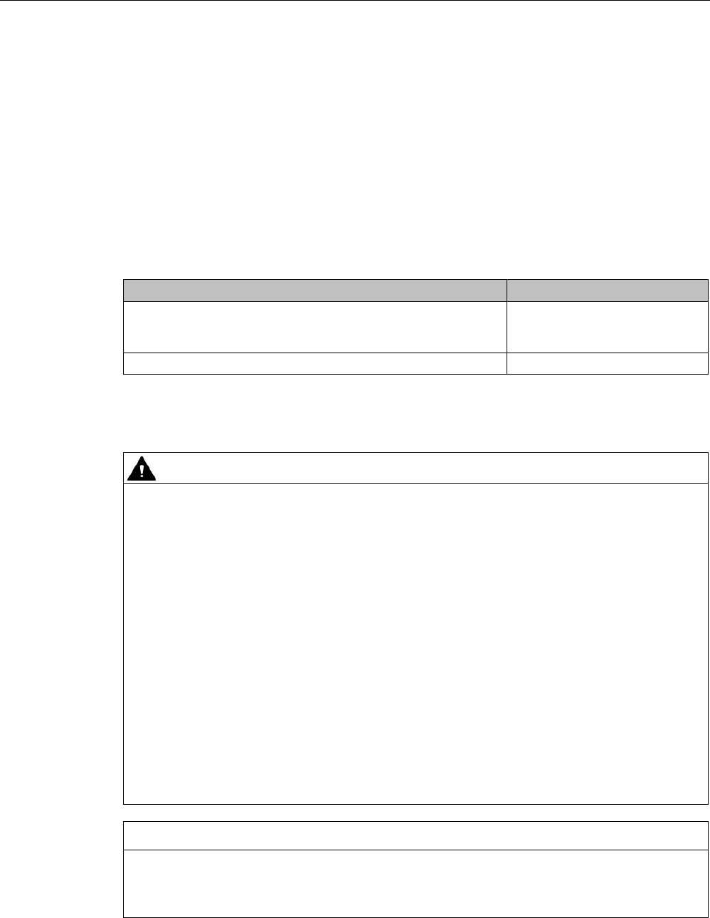
A.2.3.4
Safety Information
WARNING
Danger to life
It is not permitted to open the device or to modify the device.
The following must also be taken into account:
• Failure to observe this requirement shall constitute a revocation of the CE approval, UL
certification for the US and Canada as well as the manufacturer's warranty.
• For installation of the power supply, compliance with the DIN/VDE requirements or the
country-specific regulations is essential.
• The field of application of the power supply unit is limited to "Information technology
equipment" within the scope of validity of the EN 60950/VDE 0805 standard.
• When the equipment is installed, it must be ensured that the mains socket outlet is
freely accessible.
• The housing can reach a temperature of +25 °C during operation without any adverse
consequences. It must, however, be ensured that the power supply is covered in the
case of a housing temperature of more than +25°C to protect persons from contact with
the hot housing. Adequate ventilation of the power supply must be maintained under
these conditions.
NOTICE
Area of application of the wide-range power supply unit
The wide-range power supply unit may only be used for SIMATIC products in the
specifically described area of application and for the documented purpose.
Appendix
A.2 Accessories
SIMATIC RF200
System Manual, 07/2017, J31069-D0227-U001-A9-7619 349
If the wide-range power supply unit for SIMATIC RF systems is used for an end product
other than one from the SIMATIC RF family, the following must be taken into account:
● The electric strength test of the end product is to be based upon a maximum working
voltage of: Transition from primary to SELV: 353 VDC, 620 Vpk
● The following secondary output circuits are SELV (low voltage; SELV = Safety Extra Low
Voltage): all
● The following secondary output circuits are at non-hazardous energy levels: all
● The power supply terminals and/or connectors are suitable for field wiring if terminals are
provided.
● The maximum investigated branch circuit rating is: 20 A
● The investigated pollution degree is: 2
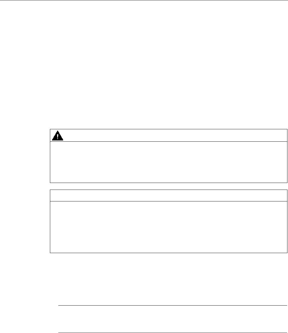
WARNING
Liability
If the wide-range power supply unit for SIMATIC RF systems is connected to an end
product other than one from the SIMATIC RF family, the end user is responsible and liable
for operation of the system or end product that includes the wide-range power supply unit
for SIMATIC RF systems.
NOTICE
Restriction to the approval of the wide-range power supply
The SIMATIC RF290R reader may only be operated with power supplies that have
received KETI approval. There is currently no KETI approval for the wide-range power
supply (6GT2898-0AAx0), which is why it may not be operated in South Korea.
To be able to operate the SIMATIC RF290 reader in South Korea, use only a power unit
that meets the following requirements: 230 VAC, 24 VDC / 3 A; KC safety approved
A.2.3.5
Connecting
● There are three different (country-specific) mains cables for the EU, UK and US.
The appropriate mains cable must be connected to the primary input of the power supply.
Note
It is only permissible to insert or remove the mains cable when the power supply is de
-
energized.
● The wide-range power supply unit has total insulation (Safety Class 2), IP65
● It can be mounted using four fixing holes.

Appendix
A.2 Accessories
SIMATIC RF200
350 System Manual, 07/2017, J31069-D0227-U001-A9-7619
A.2.3.6
Technical specifications
General technical specifications
Insulation stability (prim./sec.) Uins p/s
3.3 kVAC
Insulation resistance R
ins
>1 GΩ
Leakage current I
leak
U
in
= 230 V
AC
, f = 50 Hz
< 200 µA
Safety class (SELV)
Designed for installation in devices of Safety Class 2
Mains buffering t
h
U
in
= 230 V
AC
≥ 50 ms
Ambient temperature
-25 ℃ ... +55 ℃
Surface temperature
Module top, center
max. 96 ℃
Storage temperature
-40 ℃ ... +85 ℃
Self-heating on full-load
max. 45 K
Interference immunity
ESD
HF fields
Burst
Surge
HF injection
Mains quality test
EN 61000-4-2,
4-3 to 4-6, 4-11
Air discharge: 15 kV
10 V/m
symmetrical: 2
symmetrical: 1
10 Vrms
Cooling
Free convection
Dimensions L x W x H
175 mm x 85 mm x 35 mm
Weight
720 g
Housing / casting
UL 94-V0
Power supply class according to CSA Level 3
Degree of protection IP65
MTBF in years 255
Technical specifications - input
Rated input voltage Uin EN 60950 / UL 60950 100 to 240 VAC
120 to 353 VDC
Input frequency fin
50/60 Hz
Radio interference level
EN 55011/B
Switching frequency fsw
approx. 70 kHz typ.
Length of cable
2 m
Technical specifications - output
Output voltage tolerance ∆Uout
Uin = 230 VAC
Uout nom ≤ +2 %/-1 %
Overvoltage protection
Uout nom +20 % typ.
Noise ∆ULF
Uin = min., BW: 1 MHz
≤ 1 % Uout
Noise ∆UHF
Uin = min., BW: 20 MHz
≤ 2 % Uout

Appendix
A.2 Accessories
SIMATIC RF200
System Manual, 07/2017, J31069-D0227-U001-A9-7619 351
Technical specifications - output
Regulation
• Line regulation
• Load regulation
• Uin = min./max.
• Iout = 10...90...10 %
• ≤ 1,0 %
• ≤ 1,0 %
Short-circuit current I
max
I
nom
= 4 A (+50 °C)
105 ... 130 % I
nom
Settling time t
R
load variations
I
out
= 10 ... 90 ... 10 %
< 5 ms
Temperature coefficient ε
T
A
= -25 °C to +70 °C
0.01 %/K
Overload behavior P
over
Constant current
Short-circuit protection/
No-load response
Continuous/no-load stability
Derating
T
A
> +50 °C to +70 °C
max. 2 %/K
Connector type
M12, 4-pin;
two sockets
Technical specifications - initial configurations
Input
Outputs U1 = U2
ILoad = I1 + I2
Efficiency (%)
Remarks
110 VAC
24 VDC
0 A
No-load stability
110 VAC
24 VDC
3 A
≥ 88
220 VAC
24 VDC
0 A
No-load stability
220 VAC
24 VDC
3 A
≥ 90
Technical specifications - standards complied with
Designation
Standard
Values
Electrical safety
EN 60950 / UL 60950 / CAN/CSA 22.2 950, 3 Edition
Conducted interference EN 61000-6-3
EN 55011
Class B
Emission EN 61000-6-3
EN 55011
Class B
All values are measured at full-load and at an ambient temperature of +25 ℃ (unless
specified otherwise).
Appendix
A.2 Accessories
SIMATIC RF200
352 System Manual, 07/2017, J31069-D0227-U001-A9-7619
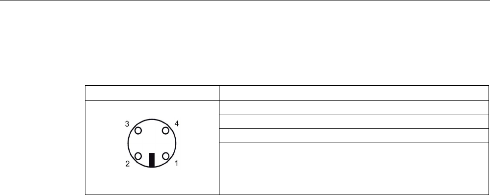
A.2.3.7
Pin assignment of DC outputs and mains connection
Table A- 7 Pin assignment for DC outputs
Assignment
(1) Ground (0V)
(2) +24 V DC
(3) +24 V DC
(4) Ground (0V)
Appendix
A.2 Accessories
SIMATIC RF200
System Manual, 07/2017, J31069-D0227-U001-A9-7619 353
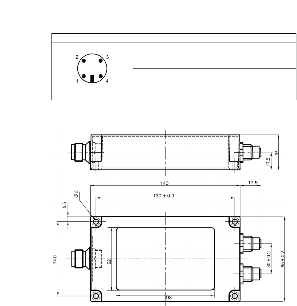
Table A- 8 Pin assignment mains connector
Assignment
(1) 100 to 240 V AC
(2) n.c.
(3) 100 to 240 V AC
(4) n.c.
A.2.3.8
Dimension drawing
Figure A-6 Dimension drawing wide-range power supply unit for SIMATIC RF systems (all
dimensions in mm)
Appendix
A.2 Accessories
SIMATIC RF200
354 System Manual, 07/2017, J31069-D0227-U001-A9-7619
A.2.3.9
Certificates and approvals
Table A- 9 Wide-range power supply unit for SIMATIC RF systems 6GT2898-0AA00 - Europe,
6GT2898-0AA10 - UK
Certificate
Description
CE approval to
2004/108/EC EMC
73/23/EEC LVD
Table A- 10 Wide-range power supply unit for SIMATIC RF systems 6GT2898-0AA20 - USA
Standard
This product is UL-certified for the US and Canada.
It meets the following safety standards:
UL 60950-1 - Information Technology Equipment Safety - Part 1:
General Requirements
CSA C22.2 No. 60950 -1 - Safety of Information Technology Equip-
ment
UL Report E 205089
Appendix
A.2 Accessories
SIMATIC RF200
System Manual, 07/2017, J31069-D0227-U001-A9-7619 355
A.2.4
Transponder holders
Table A- 11 Overview of the transponder holders and spacers
Product photo
Usable transponders
Characteristics
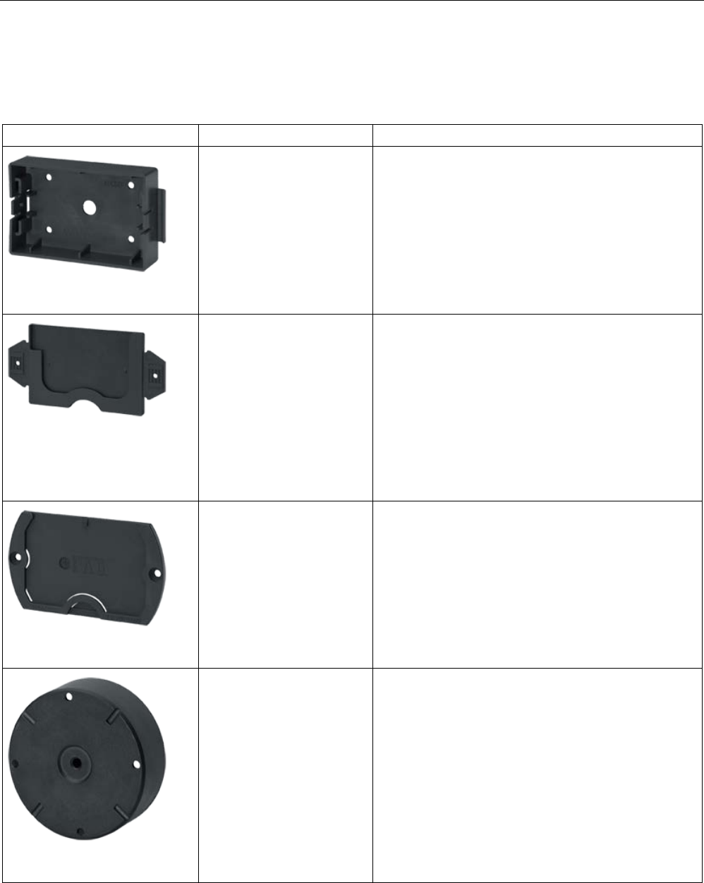
6GT2190-0AA00
• MDS D100
• MDS D200
• MDS D400
• Spacer for mounting on metal, in conjunction with the
fixing pocket 6GT2190-0AB00
• Distance from transponder to metal: 25 mm
• Mounting: 4 x M4 screws
• Material: PA6
• Weight: 31 g
• Dimensions (L x W x H): 110 x 62 x 24 mm
6GT2190-0AB00
• MDS D100
• MDS D200
• MDS D400
• Fixing pocket in conjunction with spacer 6GT2190-
0AA00
• Mounting:
– Locks into spacer
– 2 x screws/nails
– Stapled
• Material: PA6
• Weight: 12 g
• Dimensions (L x W x H): 121 x 57 x 5 mm
6GT2390-0AA00
• MDS D100
• MDS D200
• MDS D400
• Fixing pocket not suitable for mounting directly on
metal
• Mounting: 2 x M4 countersunk screws
• Material: PA6
• Weight: 21 g
• Dimensions (L x W x H): 110 x 65 x 5 mm
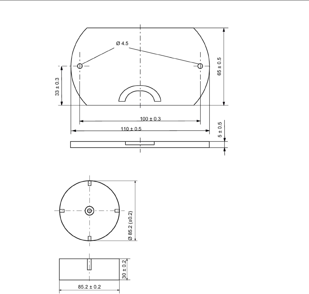
6GT2690-0AA00
• MDS D139
• MDS D339
• Spacer for mounting on metal
• Distance from transponder to metal: 30 mm
• Mounting: 1 x M5 stainless steel screw
• Tightening torque: 1.5 Nm
• Material: PPS
• Weight: 50 g
• Dimensions (Ø x H): 85 x 30 mm
Appendix
A.2 Accessories
SIMATIC RF200
356 System Manual, 07/2017, J31069-D0227-U001-A9-7619
Product photo
Usable transponders
Characteristics
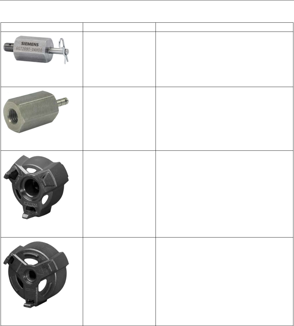
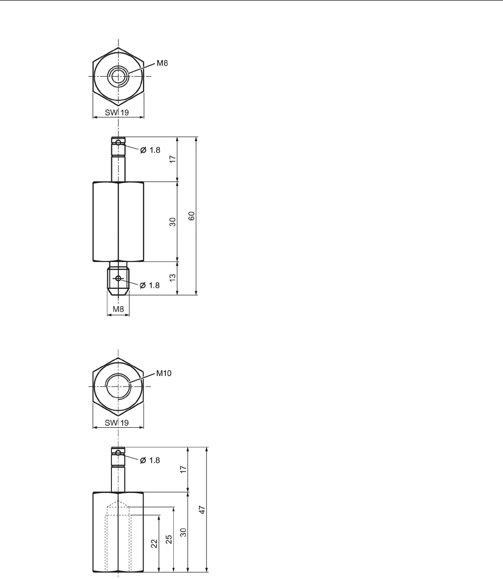
6GT2690-0AH00
• MDS D139
• MDS D339
• Quick change holder for mounting on metal
• Distance from transponder to metal: 30 mm
• Mounting: Screw-in
• Material: Stainless steel VA
• Weight: 80 g
• Dimensions (Ø x H): 22 x 60 mm
6GT2690-0AH10
• MDS D139
• MDS D339
• Quick change holder for mounting on metal
• Distance from transponder to metal: 30 mm
• Mounting: Screw-in
• Material: Stainless steel VA
• Weight: 60 g
• Dimensions (Ø x H): 22 x 47 mm
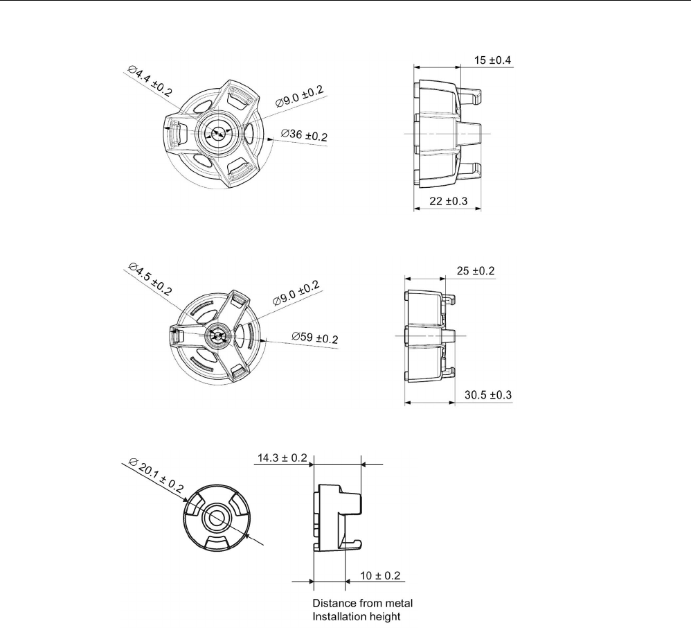
6GT2690-0AK00
• MDS D124
• MDS D324
• MDS D424
• MDS D524
• Spacer for mounting on metal
• Distance from transponder to metal: 15 mm
• Mounting: 1 x M4 countersunk screw
• Tightening torque: ≤ 1 Nm
• Material: PPS
• Weight: Approx. 4 g
• Remounting cycles: at least 10
• Dimensions (Ø x H): 36 x 22 mm
6GT2690-0AL00
• MDS D126
• MDS D426
• MDS D526
• Spacer for mounting on metal
• Distance from transponder to metal: 25 mm
• Mounting: 1 x M4 countersunk screw
• Tightening torque: ≤ 1 Nm
• Material: PA6
• Weight: Approx. 12 g
• Remounting cycles: at least 10
• Dimensions (Ø x H): 59 x 30 mm
Appendix
A.2 Accessories
SIMATIC RF200
System Manual, 07/2017, J31069-D0227-U001-A9-7619 357
Product photo
Usable transponders
Characteristics
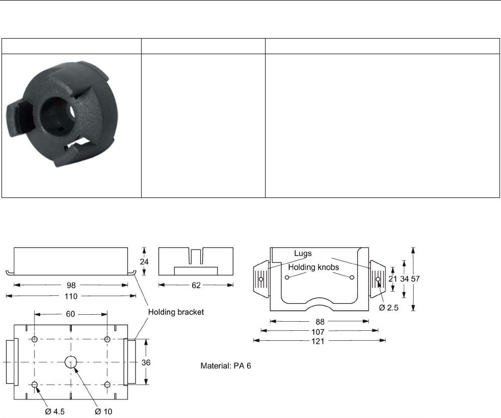
6GT2690-0AG00
• MDS D160
• MDS D460
• Spacer for mounting on metal
• Distance from transponder to metal: 10 mm
• Mounting: 1 x M3 countersunk screw
• Material: PA6
• Weight: 2 g
• Dimensions (Ø x H): 20 x 14 mm
Dimensional drawings
Figure A-7 Dimension drawing of spacer 6GT2190-0AA00 with fixing pocket 6GT2190-0AB00
Appendix
A.2 Accessories
SIMATIC RF200
358 System Manual, 07/2017, J31069-D0227-U001-A9-7619
Figure A-8 Dimension drawing of fixing pocket 6GT2390-0AA00
Figure A-9 Dimension drawing of spacer 6GT2690-0AA00
Appendix
A.2 Accessories
SIMATIC RF200
System Manual, 07/2017, J31069-D0227-U001-A9-7619 359
Figure A-10 Dimension drawing of quick change holder 6GT2690-0AH00
Figure A-11 Dimension drawing of quick change holder 6GT2690-0AH10
Appendix
A.2 Accessories
SIMATIC RF200
360 System Manual, 07/2017, J31069-D0227-U001-A9-7619
Figure A-12 Dimension drawing of spacer 6GT2690-0AK00
Figure A-13 Dimension drawing of spacer 6GT2690-0AL00
Figure A-14 Dimension drawing of spacer 6GT2690-0AG00
Appendix
A.3 Connecting cable
SIMATIC RF200
System Manual, 07/2017, J31069-D0227-U001-A9-7619 361
A.3
Connecting cable
A.3.1
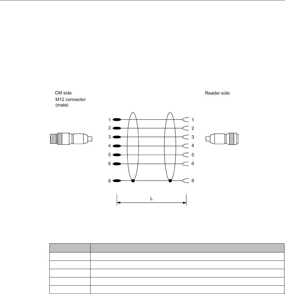
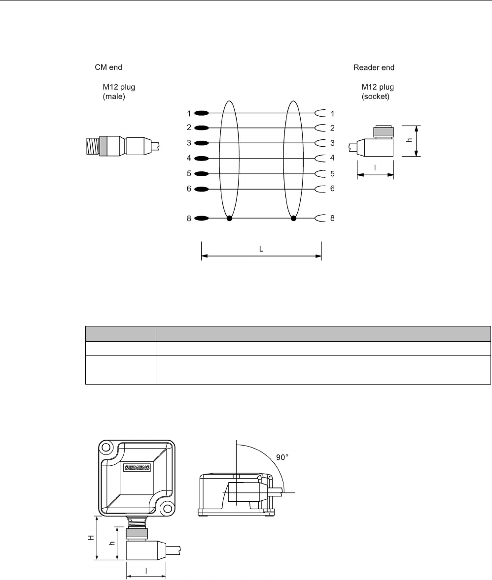
Reader RF2xxR (RS-422) with ASM 456 / RF160C / RF170C / RF180C /
RF182C
Connecting cable with straight connector
Figure A-15 Connecting cable between ASM 456, RF160C, RF170C, RF180C, RF182C and reader
RF2xxR (RS-422)
Table A- 12 Ordering data
Length L
Article number
2 m 6GT2891-4FH20
5 m
6GT2891-4FH50
10 m
6GT2891-4FN10
20 m
6GT2891-4FN20
50 m
6GT2891-4FN50
Appendix
A.3 Connecting cable
SIMATIC RF200
362 System Manual, 07/2017, J31069-D0227-U001-A9-7619
Connecting cable with angled connector
Figure A-16 Connecting cable between ASM 456, RF160C, RF170C, RF180C and RF2xxR reader
(RS-422) with angled connector
Table A- 13 Ordering data
Length L
Article number
2 m
6GT2891-4JH20
5 m
6GT2891-4JH50
10 m 6GT2891-4JN10
The angled connector has a height of h = 29 mm and a length of l = 38 mm. Remember that
due to the construction, the distance between the edge of the connector and the edge of the
reader housing (H) is higher.
Figure A-17 Distance between connector edge and housing edge
The distance between the edge of the connector and the edge of the reader housing (H) is
as follows: RF210R/RF220R = 33 mm, RF240R/RF260R = 36 mm and RF290R = 37 mm. If
you look at the reader from below, the angled connector points 90° to the right. With the
RF290R reader the angle is approximately 135°.
Appendix
A.3 Connecting cable
SIMATIC RF200
System Manual, 07/2017, J31069-D0227-U001-A9-7619 363
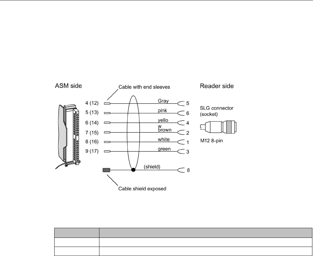
A.3.2
Reader RF2xxR (RS-422) with ASM 475
Reader connection system
The connecting cable has a length of 2 m (standard) and 5 m. Extensions up to 1000 m are
possible with the 6GT2891-4F… plug-in cables.
Figure A-18 Connecting cable between the ASM 475 and RF2xx reader (RS-422)
Table A- 14 Ordering data
Length L
Article number
2 m
6GT2891-4EH20
5 m 6GT2891-4EH50
Appendix
A.3 Connecting cable
SIMATIC RF200
364 System Manual, 07/2017, J31069-D0227-U001-A9-7619
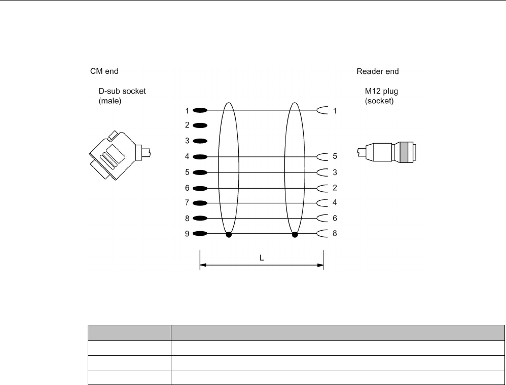
A.3.3
Reader RF2xxR (RS-422) with RF120C
Figure A-19 Connecting cable between RF120C and RF2xxR reader (RS-422)
Table A- 15 Ordering data
Length L
Article number
2 m
6GT2091-4LH20
5 m
6GT2091-4LH50
10 m
6GT2091-4LN10
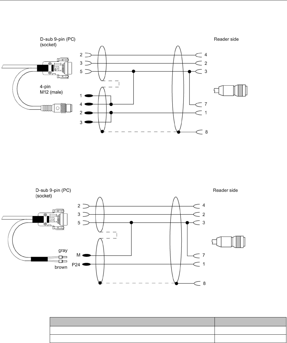
A.3.4
Reader RF240R/RF260R/RF290R (RS232) with PC
The connecting cables have a length of 5 m. The outgoing cable for the power supply has a
length of 0.5 m.
Appendix
A.3 Connecting cable
SIMATIC RF200
System Manual, 07/2017, J31069-D0227-U001-A9-7619 365
With 4-pin power supply connector
Figure A-20 Connecting cable between PC and RF240R/RF260R/RF290R (RS-232) with 4-pin power supply connector
Suitable power supply unit: e.g. wide-range power supply unit
With open ends for the power supply
Figure A-21 Connecting cable between PC and RF240R/RF260R/RF290R (RS-232) with open ends for the power supply
Table A- 16 Ordering data connecting cable
Article number
Connecting cable RS-232 with M12 male connector (4-pin), 5 m
6GT2891-4KH50
Connecting cable RS-232 with open ends (5 m)
6GT2891-4KH50-0AX0
Appendix
A.3 Connecting cable
SIMATIC RF200
366 System Manual, 07/2017, J31069-D0227-U001-A9-7619
A.3.5
Reader RF290R
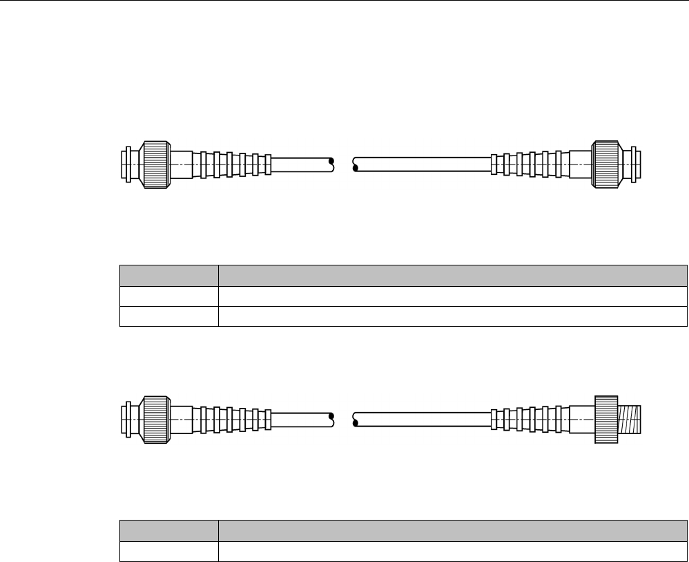
Antenna connecting cable
Figure A-22 ANT cable ↔ ANT Dx (3.3 m / 10.5 m)
Table A- 17 Ordering data
Length L
Article number
3.3 m
6GT2691-0CH33
10.5 m
6GT2691-0CN10
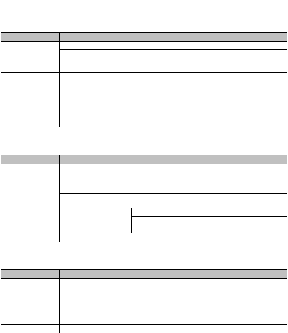
Antenna extension cable
Figure A-23 Antenna extension cable (7.2 m)
Table A- 18 Ordering data
Length L
Article number
7.2 m
6GT2691-0DH72

Appendix
A.4 Ordering data
SIMATIC RF200
System Manual, 07/2017, J31069-D0227-U001-A9-7619 367
A.4
Ordering data
RF200 components
Table A- 19 RF200 reader
Readers
Description
Article number
RF210R
• With RS-422 interface (3964R)
• IP67
• Operating temperature: -25 °C ... +70 °C
• Dimensions (L x Ø): 83 x 18 mm
• with integrated antenna
6GT2821-1AC10
RF210M
• With RS-422 interface (3964R)
• IP54
• Operating temperature: -20 °C ... +50 °C
• Dimensions with handle (L x W x H) 195 x 26 x 140 mm
• with integrated antenna
6GT2823-0AA00
RF220R
• With RS-422 interface (3964R)
• IP67
• Operating temperature: -25 °C ... +70 °C
• Dimensions (L x Ø): 83 x 30 mm
• with integrated antenna
6GT2821-2AC10
RF240R
• With RS-422 interface (3964R)
• IP67
• Operating temperature: -20 °C ... +70 °C
• Dimensions (L x W x H): 50 x 50 x 30 mm
• with integrated antenna
6GT2821-4AC10
RF240R
• With RS-232 interface (3964R)
• IP67
• Operating temperature: -20 °C ... +70 °C
• Dimensions (L x W x H): 50 x 50 x 30 mm
• with integrated antenna
6GT2821-4AC11
RF240R
• With RS-232 interface (ASCII)
• IP67
• Operating temperature: -20 °C ... +70 °C
• Dimensions (L x W x H): 50 x 50 x 30 mm
• with integrated antenna
6GT2821-4AC40

Appendix
A.4 Ordering data
SIMATIC RF200
368 System Manual, 07/2017, J31069-D0227-U001-A9-7619
Readers
Description
Article number
RF250R
• With RS-422 interface (3964R)
• IP67
• Operating temperature: -20 °C ... +70 °C
• Dimensions (L x W x H): 50 x 50 x 30 mm
• Reader with connections for external antennas ANT 8, ANT 12, ANT
18, ANT 30
6GT2821-5AC10
RF250R
• With RS-232 interface (ASCII)
• IP67
• Operating temperature: -20 °C ... +70 °C
• Dimensions (L x W x H): 50 x 50 x 30 mm
• Reader with connections for external antennas ANT 8, ANT 12, ANT
18, ANT 30
6GT2821-5AC40
RF260R
• With RS-422 interface (3964R)
• IP67
• Operating temperature: -20 °C ... +70 °C
• Dimensions (L x W x H): 75 x 75 x 41 mm
• with integrated antenna
6GT2821-6AC10
RF260R
• With RS-232 interface (3964R)
• IP67
• Operating temperature: -20 °C ... +70 °C
• Dimensions (L x W x H): 75 x 75 x 41 mm
• with integrated antenna
6GT2821-6AC11
RF260R
• With RS-232 interface (ASCII)
• IP67
• Operating temperature: -20 °C ... +70 °C
• Dimensions (L x W x H): 75 x 75 x 41 mm
• with integrated antenna
6GT2821-6AC40
RF280R
• With RS-422 interface (3964R)
• IP67
• Operating temperature: -25 … +70 °C
• Dimensions (L x W x H): 160 x 80 x 41 mm
• with integrated antenna
6GT2821-8AC10
RF280R
• With RS-232 interface (ASCII)
• IP67
• Operating temperature: -25 … +70 °C
• Dimensions (L x W x H): 160 x 80 x 41 mm
• with integrated antenna
6GT2821-8AC40

Appendix
A.4 Ordering data
SIMATIC RF200
System Manual, 07/2017, J31069-D0227-U001-A9-7619 369
Readers
Description
Article number
RF290R
• With RS-232 interface (Advanced protocol) and
RS-422 interface (3964R)
• IP65
• Operating temperature: -20 °C ... +55 °C
• Dimensions (L x W x H): 200 x 140 x 80 mm
• Long-range reader with the option of connecting external antennas
ANT D5, ANT D6, ANT D10
6GT2821-0AC12
RF310M
• IP65
• Operating temperature: -20 °C ... +50 °C
• Dimensions (L x W x H): 277 x 100 x 44 mm
• Mobile reader with integrated antenna
6GT2803-1AC00
RF310M
• IP65
• Operating temperature: -20 °C ... +50 °C
• Dimensions (L x W x H): 277 x 100 x 44 mm
• Mobile reader with connections for external antennas ANT 8, ANT 12,
ANT 18, ANT 30
6GT2803-1AC10
Table A- 20 ISO transponder
ISO transponder
Description
Article number
MDS D100
• IP68
• Memory size: 112 bytes of EEPROM user memory
• Operating temperature: -25 °C ... +80 °C
• Dimensions (L x W x H): 85.6 x 54 x 0.9 mm
• Credit card format
6GT2600-0AD10
MDS D117
• IP68
• Memory size: 112 bytes of EEPROM user memory
• Operating temperature: -25 °C ... +85 °C
• Dimensions (Ø x H): 4 x 5 mm
6GT2600-0AG00
MDS D124
• IP68; IPx9K
• Memory size: 112 bytes of EEPROM user memory
• Operating temperature: -25 °C ... +180 °C
• Dimensions (Ø x H): 27 (±0.2) x 4 (±0.2) mm
6GT2600-0AC10
MDS D126
• IP68
• Memory size: 112 bytes of EEPROM user memory
• Operating temperature: -25 °C ... +85 °C
• Dimensions (Ø x H): 50 x 3.6 mm
• Round design with mounting hole
6GT2600-0AE00

Appendix
A.4 Ordering data
SIMATIC RF200
370 System Manual, 07/2017, J31069-D0227-U001-A9-7619
ISO transponder
Description
Article number
MDS D127
• IP68; IPx9K
• Memory size: 112 bytes of EEPROM user memory
• Operating temperature: -25 °C ... +125 °C
• Dimensions (Ø x H): M6 x 5 (±0.2) mm
6GT2600-0AF00
MDS D139
• IP68; IPx9K
• Memory size: 112 bytes of EEPROM user memory
• Operating temperature: up to +200 °C / +220 °C
• Dimensions (Ø x H): 85 (±0.5) x 15 (-1.0) mm
6GT2600-0AA10
MDS D160
• IP68; IPx9K
• Memory size: 112 bytes of EEPROM user memory
• Operating temperature: -25 °C...+70 °C
• Dimensions (Ø x H): 16 (±0.2) x 3.0 (±0.2) mm
• Laundry tag for cyclic applications
6GT2600-0AB10
MDS D165
• IP65
• Memory size: 112 bytes of EEPROM user memory
• Operating temperature: -25 °C ... +85 °C
• Dimensions (L x W): 86 x 54 mm
• Smartlabel (PET) in credit card format
6GT2600-1AB00-0AX0
MDS D200
• IP67
• Memory size: 256 bytes of EEPROM user memory
• Operating temperature: -20 °C ... +60 °C
• Dimensions (L x W x H): 86 x 54 x 0.8 mm
• Credit card format
6GT2600-1AD00-0AX0
MDS D261
• IP65
• Memory size: 256 bytes of EEPROM user memory
• Operating temperature: -25 °C ... +85 °C
• Dimensions (L x W): 55 x 55 mm
• Smartlabel (PET), small design
6GT2600-1AA00-0AX0
MDS D324
• IP67; IPx9K
• Memory size: 992 bytes of EEPROM user memory
• Operating temperature: -25 °C ... +125 °C
• Dimensions (Ø x H): 27 (±0.2) x 4 (±0.2) mm
6GT2600-3AC00
MDS D339
• IP68; IPx9K
• Memory size: 992 bytes of EEPROM user memory
• Operating temperature: -25 °C ... +220 °C
• Dimensions (Ø x H): 85 (±0.5) x 15 (-1.0) mm
6GT2600-3AA10

Appendix
A.4 Ordering data
SIMATIC RF200
System Manual, 07/2017, J31069-D0227-U001-A9-7619 371
ISO transponder
Description
Article number
MDS D400
• IP67
• Memory size: 2000 bytes of FRAM user memory
• Operating temperature: -25 °C ... +60 °C
• Dimensions (L x W x H) 85.6 (±0.3) × 54 (±0.2) × 0.8 (±0.05) mm
6GT2600-4AD00
MDS D421
• IP67; IPx9K
• Memory size: 2000 bytes of FRAM user memory
• Operating temperature –25 °C ... +85 °C
• Dimensions (Ø x H): 10 x 4.5 mm
6GT2600-4AE00
MDS D422
• IP68
• Memory size: 2000 bytes of FRAM user memory
• Operating temperature: -25 °C ... +85 °C
• Dimensions (Ø x H): M20 x 6 (±0.2) mm
• Can be screwed into metal (flush-mounted)
6GT2600-4AF00
MDS D423
• IP68; IPx9K
• Memory size: 2000 bytes of FRAM user memory
• Operating temperature: -25 °C ... +85 °C
• Dimensions (Ø x H): 30 (+0.2/-0.5) x 8 (-0.5) mm
6GT2600-4AA00
MDS D424
• IP67; IPx9K
• Memory size: 2000 bytes of FRAM user memory
• Operating temperature: -25 °C ... +125 °C
• Dimensions (Ø x H): 27 (±0.2) x 4 (±0.2) mm
6GT2600-4AC00
MDS D425
• IP68; IPx9K
• Memory size: 2000 bytes of FRAM user memory
• Operating temperature: -25 °C ... +85 °C
• Dimensions (Ø x H): 24 X 10 mm; M6 thread
• Screw transponder
6GT2600-4AG00
MDS D426
• IP68
• Memory size: 2000 bytes of FRAM user memory
• Operating temperature: -25 °C ... +85 °C
• Dimensions (Ø x H): 50 x 3.6 mm
• Round design with mounting hole
6GT2600-4AH00
MDS D428
• IP68; IPx9K
• Memory size: 2000 bytes of FRAM user memory
• Operating temperature: -25 °C ... +85 °C
• Dimensions (Ø x H): 18(±1) x 20(±1) mm (without thread); thread
M8
6GT2600-4AK00-0AX0

Appendix
A.4 Ordering data
SIMATIC RF200
372 System Manual, 07/2017, J31069-D0227-U001-A9-7619
ISO transponder
Description
Article number
MDS D460
• IP67; IPx9K
• Memory size: 2000 bytes of FRAM user memory
• Operating temperature: -25 °C ... +85 °C
• Dimensions (Ø x H): 16 (±0.2) x 3.0 (±0.2) mm
6GT2600-4AB00
MDS D521
• IP67; IPx9K
• Memory size: 8192 bytes of FRAM user memory
• Operating temperature –25 °C ... +85 °C
• Dimensions (Ø x H): 10 x 4.5 mm
6GT2600-5AE00
MDS D522
• IP68
• Memory size: 8192 bytes of FRAM user memory
• Operating temperature: -25 °C ... +85 °C
• Dimensions (Ø x H): M20 x 6 (±0.2) mm
• Can be screwed into metal (flush-mounted)
6GT2600-5AF00
MDS D522
Special variants
• IP68
• Memory size: 8192 bytes of FRAM user memory
• Operating temperature: -25 °C ... +85 °C
• Dimensions (Ø x H): 18 (+0.1) x 5.2 mm
• Can be clipped into metal (flush-mounted)
6GT2600-5AF00-0AX0
MDS D524
• IP67
• Memory size: 8192 bytes of FRAM user memory
• Operating temperature: -25 °C ... +85 °C
• Dimensions (Ø x H): 27 (±0.2) x 4 (±0.2) mm
6GT2600-5AC00
MDS D526
• IP67; IPx9K
• Memory size: 8192 bytes of FRAM user memory
• Operating temperature: -25 °C ... +85 °C
• Dimensions (Ø x H): 50 x 3.6 mm
• Round design with mounting hole
6GT2600-4AH00
MDS D528
• IP68; IPx9K
• Memory size: 8192 bytes of FRAM user memory
• Operating temperature: -25 °C ... +85 °C
• Dimensions (Ø x H): 18(±1) x 20(±1) mm (without thread); thread
M8
6GT2600-5AK00

Appendix
A.4 Ordering data
SIMATIC RF200
System Manual, 07/2017, J31069-D0227-U001-A9-7619 373
Table A- 21 Communication modules/interface modules
ASM/
communications
module
Description
Article number
ASM 456
ASM 456 for PROFIBUS DP-V1
max. 2 readers connectable
6GT2002-0ED00
ASM 475
ASM 475 for SIMATIC S7
max. 2 RF2xxR readers with RS-422 can be connected in parallel without a
front connector
6GT2002-0GA10
RF120C
Communications module RF120C for SIMATIC S7-1200
6GT2002-0LA00
RF160C
Communications module RF160C for PROFIBUS DP V0
max. 2 readers connectable
6GT2002-0EF00
RF170C
RF170C communications module
6GT2002-0HD00
RF170C connecting block
6GT2002-1HD00
RF180C
RF180C communications module
max. 2 SLGs or readers can be connected
6GT2002-0JD00
Connecting block M12, 7/8'' (5-pin)
6GT2002-1JD00
Connecting block M12, 7/8'' (4-pin)
6GT2002-4JD00
Push-pull connecting block, RJ-45
6GT2002-2JD00
RF182C
RF182C communication module
Max. 2 SLGs or readers can be connected
6GT2002-0JD10
Connecting block M12, 7/8'' (5-pin)
6GT2002-1JD00
Connecting block M12, 7/8'' (4-pin)
6GT2002-4JD00
Push-pull connecting block, RJ-45
6GT2002-2JD00
RFID 181EIP
RF182C communications module
max. 2 SLGs or readers can be connected
6GT2002-0JD20
Connecting block M12, 7/8'' (5-pin)
6GT2002-1JD00
Connecting block M12, 7/8'' (4-pin) 6GT2002-4JD00
Push-pull connecting block, RJ-45
6GT2002-2JD00
Table A- 22 Antennas
Antennas
Description
Article number
ANT 3
• IP67
• Operating temperature: -25 °C ... +70 °C
• Dimensions (L x W x H): 50 x 28 x 10 mm
• without antenna connecting cable
6GT2398-1CD30-0AX0
• incl. one plug-in antenna connecting cable 3 m 6GT2398-1CD40-0AX0
ANT 8
• IP67
• Operating temperature: -25 °C ... +70 °C
• Dimensions (Ø x L): M8 x 40 mm
• without antenna connecting cable
6GT2398-1CF00
• incl. one plug-in antenna connecting cable 3 m 6GT2398-1CF10

Appendix
A.4 Ordering data
SIMATIC RF200
374 System Manual, 07/2017, J31069-D0227-U001-A9-7619
Antennas
Description
Article number
ANT 12
• IP67
• Operating temperature: -25 °C ... +70 °C
• Dimensions (Ø x L): M12 x 40 mm
• incl. one integrated antenna connecting cable 0.6 m
6GT2398-1CC10
• incl. one plug-in antenna connecting cable 3 m 6GT2398-1CC00
ANT 18
• IP67 (front)
• Operating temperature: -25 °C ... +70 °C
• Dimensions (Ø x L): M18 x 55 mm
• incl. one integrated antenna connecting cable 0.6 m
6GT2398-1CA10
• incl. one plug-in antenna connecting cable 3 m 6GT2398-1CA00
ANT 30
• IP67
• Operating temperature: -25 °C ... +70 °C
• Dimensions (Ø x L): M30 x 58 mm
• incl. one plug-in antenna connecting cable 3 m
6GT2398-1CD00
ANT D5
• IP65
• Operating temperature: -20 °C ... +55 °C
• Dimensions (L x W x H): 380 x 380 x 110 mm
• incl. one antenna connecting cable 3.3 m
6GT2698-5AA10
ANT D6
• IP65
• Operating temperature: -20 °C ... +55 °C
• Dimensions (L x W x H): 580 x 480 x 110 mm
• incl. one antenna connecting cable 3.3 m
6GT2698-5AB00
ANT D10
• IP65
• Operating temperature: -20 °C ... +55 °C
• Dimensions (L x W x H): 1150 x 365 x 115 mm
• incl. one antenna connecting cable 3.3 m
6GT2698-5AF00
Accessories
Table A- 23 Reader accessories
Readers
Accessories
Article number
RF290R
Adapter for mounting on a DIN rail
(pack of 3)
6GK5798-8ML00-0AB3
Appendix
A.4 Ordering data
SIMATIC RF200
System Manual, 07/2017, J31069-D0227-U001-A9-7619 375
Table A- 24 ISO transponder accessories
Transponder
Accessories
Article number
MDS D100 / D200 /
D400
Spacer
6GT2190-0AA00
Fixing pocket 6GT2190-0AB00
Securing pocket
(cannot be mounted directly on metal)
6GT2390-0AA00
MDS D139 / D339
Spacer (Ø x H): 85 x 30 mm 6GT2690-0AA00
Quick change holder (Ø x H): 22 x 48 mm
6GT2690-0AH00
MDS D124 / D324 /
D424 / D524
Spacer (Ø x H): 35 x 15 mm 6GT2690-0AK00
MDS D126 / D426 /
D526
Spacer (Ø x H): 60 x 30 mm 6GT2690-0AL00
MDS D160 / D460
Spacer (Ø x H): 20 x 15 mm
6GT2690-0AG00
Table A- 25 Antenna accessories
Antennas
Accessories
Article number
ANT 3 / ANT 8
Antenna connecting cable
with M8 plug (with angled plug)
6GT2391-0AH30
ANT D5 / ANT D6 /
ANT D10
Antenna splitter
(incl. one antenna connecting cable 3.3 m)
6GT2690-0AC00
Antenna multiplexer SIMATIC RF260X
(incl. one antenna connecting cable 0.4 m)
6GT2894-0EA00
Antenna cable
3.3 m
6GT2691-0CH33
10.5 m
6GT2691-0CN10
Antenna cable extension
7.2 m
6GT2691-0DH72
ANT D6
Cover
6GT2690-0AD00
Table A- 26 Accessories - connecting cable RF200 reader ↔ PC
Connecting cable
Accessories
Article number
RF240R / RF260R /
RF290R (RS-232)
and PC
Connecting cable RS-232
with M12 male connector (4-pin), 5 m
6GT2891-4KH50
Connecting cable RS-232
with open ends, 5 m
6GT2891-4KH50-0AX0
RF290R
Antenna cable 3.3 m
6GT2691-0CH33
Antenna cable 10.5 m
6GT2691-0CN10
RF290R
Antenna extension cable 7.2 m
6GT2691-0DH72

Appendix
A.4 Ordering data
SIMATIC RF200
376 System Manual, 07/2017, J31069-D0227-U001-A9-7619
Table A- 27 Accessories - connecting cable communications module/ASM ↔ reader
Connecting cables
Description
Length
Article number
ASM 456 / RF160C /
RF170C / RF180C
and RF2xxR reader
(RS-422)
2 m
6GT2891-4FH20
5 m 6GT2891-4FH50
10 m
6GT2891-4FN10
20 m
6GT2891-4FN20
50 m
6GT2891-4FN50
ASM 456 / RF160C /
RF170C / RF180C
and RF2xxR reader
(RS-422) with angled
connector
2 m
6GT2891-4JH20
5 m
6GT2891-4JH50
10 m 6GT2891-4JN10
ASM 475
and RF2xxR reader
(RS-422)
2 m
6GT2891-4EH20
5 m 6GT2891-4EH50
RF120C
and reader RF3xxR
(RS-422)
2 m
6GT2091-4LH20
5 m
6GT2091-4LH50
10 m
6GT2091-4LN10
Table A- 28 RFID accessories, general
RFID general
Article number
DVD "Ident Systems Software & Documentation"
6GT2080-2AA20
Wide-range power supply unit for SIMATIC RF systems
(100 - 240 VAC / 24 VDC / 3 A)
with country-specific power cable/plug, 2 m
EU: 6GT2898-0AA00
UK: 6GT2898-0AA10
US: 6GT2898-0AA20
24 V connecting cable, 5 m
6GT2491-1HH50
M12 connector, 4-pin for wide range power supply unit, pack of 3
6GK1907-0DB10-6AA3

Appendix
A.5 Service & Support
SIMATIC RF200
System Manual, 07/2017, J31069-D0227-U001-A9-7619 377
A.5
Service & Support
Industry Online Support
In addition to the product documentation, the comprehensive online information platform of
Siemens Industry Online Support at the following Internet address:
Link 1: (https://support.industry.siemens.com/cs/de/en/)
Apart from news, there you will also find:
● Project information: Manuals, FAQs, downloads, application examples etc.
● Contacts, Technical Forum
● The option submitting a support query:
link 2: (https://support.industry.siemens.com/My/ww/en/requests)
● Our service offer:
Right across our products and systems, we provide numerous services that support you
in every phase of the life of your machine or system - from planning and implementation
to commissioning, through to maintenance and modernization.
You will find contact data on the Internet at the following address:
Link 3: (http://w3.siemens.com/aspa_app)
RFID homepage
For general information about our identification systems, visit RFID homepage
(http://w3.siemens.com/mcms/identification-systems/).
Online catalog and ordering system
The online catalog and the online ordering system can also be found on the Industry Mall
Homepage (https://mall.industry.siemens.com).
SITRAIN - Training for Industry
The training offer includes more than 300 courses on basic topics, extended knowledge and
special knowledge as well as advanced training for individual sectors - available at more
than 130 locations. Courses can also be organized individually and held locally at your
location.
You will find detailed information on the training curriculum and how to contact our customer
consultants at the following Internet address:
Link: (http://sitrain.automation.siemens.com/sitrainworld/)

Appendix
A.5 Service & Support
SIMATIC RF200
378 System Manual, 07/2017, J31069-D0227-U001-A9-7619
SIMATIC RF200
System Manual, 07/2017, J31069-D0227-U001-A9-7619 379
Index
A
Accessories
SIMATIC RF260X antenna multiplexer, 339
Wide-range power supply unit, 347
ANT 12
Definition of distance D, 179
ANT 18
Definition of distance D, 184
ANT 30
Definition of distance D, 190
ANT 8
Definition of distance D, 174
ANT D10
Definition of distance D, 206
Dimensions, 208
Transmission window, 204
ANT D5
Definition of distance D, 195
ANT D6
Definition of distance D, 200
Antenna
ANT 1, 161
ANT 12, 177
ANT 18, 182
ANT 3, 166
ANT 30, 187
ANT 8, 172
ANT D10, 203
ANT D5, 192
ANT D6, 198
Antenna splitter, 337
Technical specifications, 338
Application Planning
SIMATIC RF200, 27
Approvals, 335
Article numbers, 367
ASM 475
Assignment for connecting cable, 363
Pin assignment, 363
C
Certificates, 335
Communication time
Calculating, 37
D
Detection area, 34
Diagnostic functions
ISO transponder, 333
Direction of motion
Transponder, 34
Dwell time
Transponder, 36
Dynamic mode, 35
Dwell time of the transponder, 36
F
Field data
RF210R, 39
RF220R, 40
RF240R, 40
RF260R, 44
RF280R, 45
RF290R, 46
Flush-mounting
of transponders and readers, 52
I
Input parameters, 325
Installation
Several readers, 53
Installation guidelines, 50
ISO transponder
Resistance to chemicals, 93
M
MDS D100 transponder
Technical specifications, 212
MDS D117 transponder
Technical specifications, 216
MDS D124 Transponder
Technical specifications, 220
MDS D127 transponder
Technical specifications, 230
MDS D160 transponder
Technical specifications, 240

Index
SIMATIC RF200
380 System Manual, 07/2017, J31069-D0227-U001-A9-7619
MDS D200 transponder
Technical specifications, 248
MDS D339 transponder
Technical specifications, 260
MDS D424 Transponder
Technical specifications, 283
MDS D425 Transponder
Technical specifications, 286
MDS D428 transponder
Technical specifications, 293
MDS D460 Transponder
Technical specifications, 297
MDS D521 transponder
Technical specifications, 301
MDS D522 transponder
Technical specifications, 305
MDS D524 transponder
Technical specifications, 314
MDS D526 transponder
Technical specifications, 318
MDS D528 transponder
Technical specifications, 321
Metal
Influence on the transmission window, 54
Metal-free space
Reader RF280R, 74
Reader RF290R, 76
RF210R reader, 55
RF220R reader, 58
RF240R reader, 60
RF250R reader, 63
RF260R reader, 71
Minimum distance
Antenna to antenna, 50
Reader to reader, 50
Transponder to transponder, 48
O
Ordering data, 367
Accessories, 374
Antenna multiplexer SIMATIC RF260X, 339
Antenna splitter, 337
Antennas, 373
Interface modules/communication Modules, 373
ISO transponder, 369
Readers, 367
Wide-range power supply unit, 348
P
Parameter assignment
Function blocks, 325
R
Reader RF280R
Metal-free space, 74
Reader RF290R
Metal-free space, 76
Reader SIMATIC RF210M, 110
Reader SIMATIC RF240R, 122
Reader SIMATIC RF280R, 140
Reader SIMATIC RF290R, 147
Readers
Mounting, 53
Reducing interference due to metal, 51
Resistance to chemicals
Transponder, 93
RF200 transponder
Resistance to chemicals, 93
RF210R reader
Metal-free space, 55
RF220R reader
Metal-free space, 58
RF240R reader
Metal-free space, 60
RF250R reader
Metal-free space, 63
RF260R reader
Metal-free space, 71
S
Selection criteria
SIMATIC RF200 components, 27
SIMATIC RF210R reader, 104
SIMATIC RF220R reader, 116
SIMATIC RF250R reader, 128
SIMATIC RF260R reader, 134
SIMATIC RF260X, 339
SIMATIC RF260X antenna multiplexer, 339
Static mode, 35
Dwell time of the transponder, 36
Support, 377
T
Technical specifications
MDS D100 transponder, 212

Index
SIMATIC RF200
System Manual, 07/2017, J31069-D0227-U001-A9-7619 381
MDS D117 transponder, 216
MDS D124 Transponder, 220
MDS D127 transponder, 230
MDS D160 transponder, 240
MDS D200 transponder, 248
MDS D339 transponder, 260
MDS D424 Transponder, 283
MDS D425 Transponder, 286
MDS D428 transponder, 293
MDS D460 Transponder, 297
MDS D521 transponder, 301
MDS D522 transponder, 305
MDS D524 transponder, 314
MDS D526 transponder, 318
MDS D528 transponder, 321
Transponder MDS D126, 226
Transponder MDS D139, 235
Transponder MDS D165, 244
Transponder MDS D261, 251
Transponder MDS D324, 255
Transponder MDS D400, 266
Transponder MDS D421, 272
Transponder MDS D422, 275
Transponder MDS D423, 279
Transponder MDS D426, 290
Tracking
Tolerance, 30
Tracking tolerances, 30
Training, 377
Transmission gaps, 38
Transmission window
Impact of metal, 54
Width, 30
Transponder
Detection area, 34
Directions of motion, 34
Dwell time, 36
Mounting on metal, 53
Transponder MDS D126
Technical specifications, 226
Transponder MDS D139
Technical specifications, 235
Transponder MDS D165
Technical specifications, 244
Transponder MDS D261
Technical specifications, 251
Transponder MDS D324
Technical specifications, 255
Transponder MDS D400
Technical specifications, 266
Transponder MDS D421
Technical specifications, 272
Transponder MDS D422
Technical specifications, 275
Transponder MDS D423
Technical specifications, 279
Transponder MDS D426
Technical specifications, 290
U
User data
calculating, 37
W
Wide-range power supply unit, 347
Pin assignment for DC outputs, 352

Index
SIMATIC RF200
382 System Manual, 07/2017, J31069-D0227-U001-A9-7619