Siemens RF280R RFID Reader 13.56 MHz User Manual SIMATIC RF200
Siemens AG RFID Reader 13.56 MHz SIMATIC RF200
Siemens >
Contents
- 1. SYH_RF200_76_Part 1
- 2. SYH_RF200_76_Part 2
- 3. SYH_RF200_76_Part 3
SYH_RF200_76_Part 2
Antennas
6.3 ANT 8
SIMATIC RF200
System Manual, 07/2017, J31069-D0227-U001-A9-7619 173
6.3.3
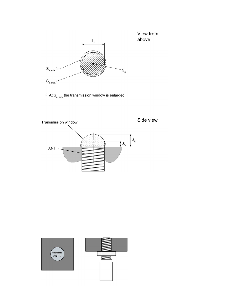
Transmission window
Ld
Length of the transmission window (= 3 mm)
Sa
Operating distance between antenna and transponder
Sg Limit distance (maximum clear distance between upper surface of the reader and the antenna,
at which the transmission can still function under normal conditions)
Figure 6-10 Transmission window ANT 8
6.3.4
Flush-mounted in metal
Figure 6-11 ANT 8 flush-mounted in metal
Antennas
6.3 ANT 8
SIMATIC RF200
174 System Manual, 07/2017, J31069-D0227-U001-A9-7619
6.3.5
Minimum spacing
Note
Extension of the data transmission time if distance values are undershot
If the distance values specified in the tables are undershot, it is possible that the inductive
fields will be affected. In this case, the data transmission time can increase unpredictab
ly or
a command is aborted with an error.
For this reason, please observe the values in the tables.
Minimum distances from transponder to transponder (without multitag mode)
Table 6- 11 Minimum distances transponder edge to transponder edge
MDS D117 / MDS D127
MDS D421 / MDS D521
RF250R with ANT 8
≥ 20 mm ≥ 30 mm
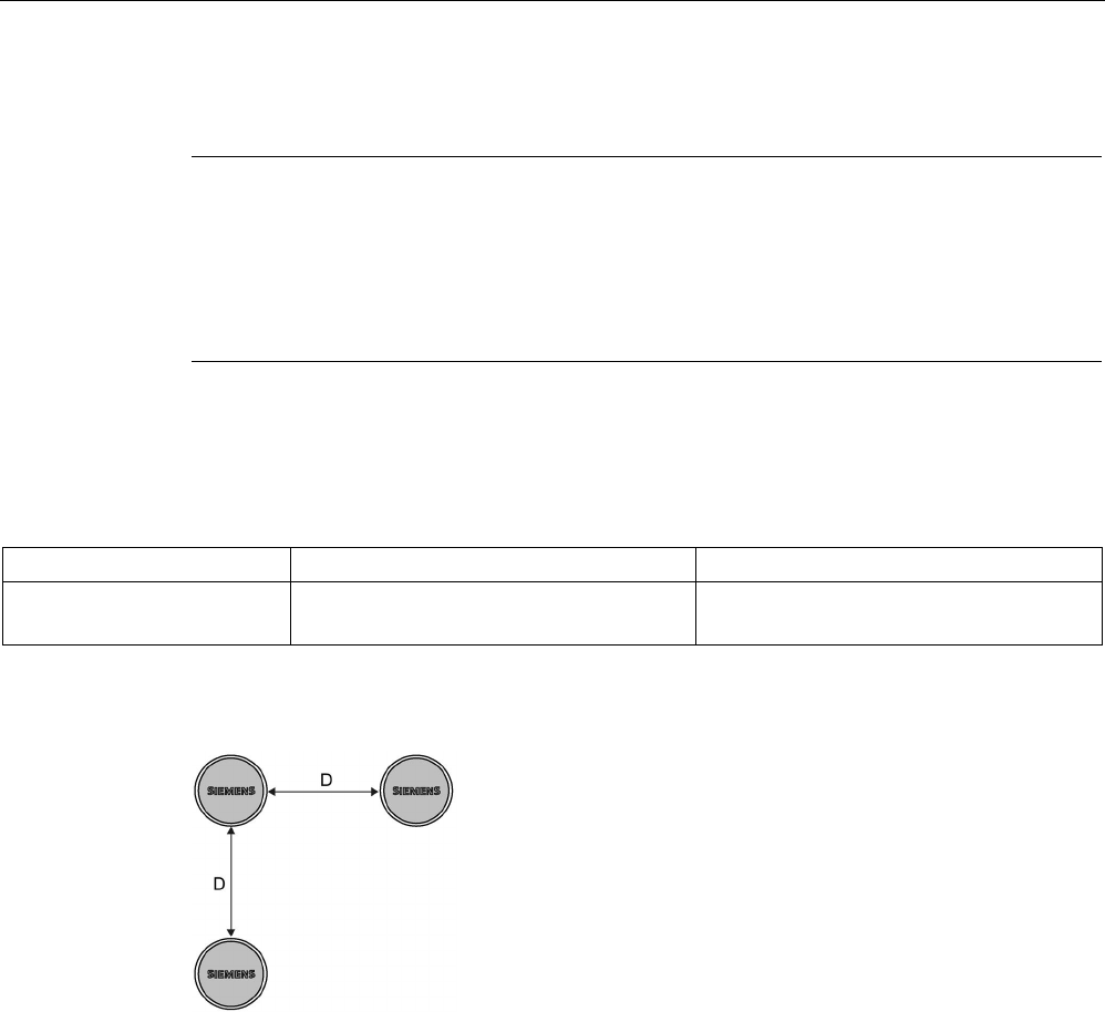
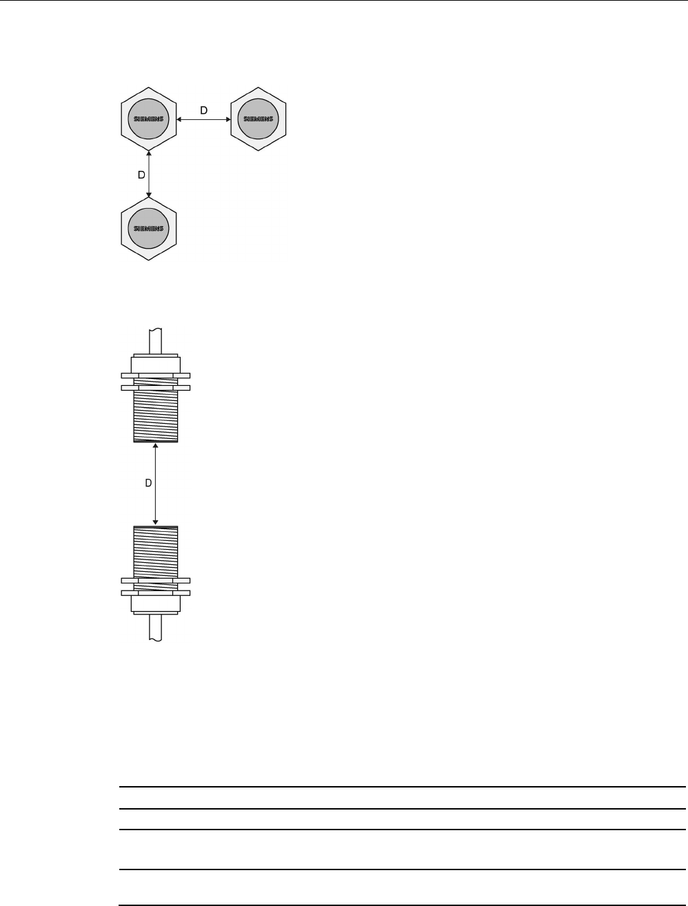
Definition of distance D
D
≥ 50 mm
Figure 6-12 Minimum distance for ANT 8
Antennas
6.3 ANT 8
SIMATIC RF200
System Manual, 07/2017, J31069-D0227-U001-A9-7619 175
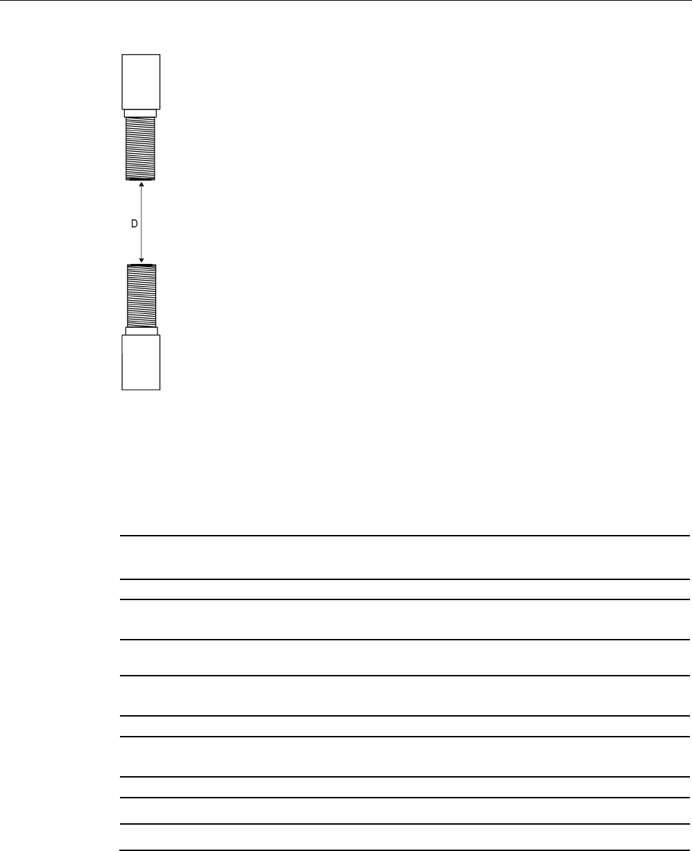
D
≥ 50 mm
Figure 6-13 Face-to-face distance between two ANT 8s
6.3.6
Technical data
6GT2398-1CF10
6GT2398-1CF00
Product type designation
ANT 8
Electrical data
Maximum write/read distance ANT ↔ transponder
(Sg)
4 mm
Interfaces
Plug connection
4-pin (pin on antenna side)
Mechanical specifications
Housing
• Material • Stainless steel
• Color • silver
Antennas
6.3 ANT 8
SIMATIC RF200
176 System Manual, 07/2017, J31069-D0227-U001-A9-7619
6GT2398-1CF10
6GT2398-1CF00
Permitted ambient conditions
Ambient temperature
• During operation • -25 ℃ ... +70 ℃
• During transportation and storage • -40 °C ... +85 °C
Degree of protection to EN 60529
IP67
Shock according to EN 60721-3-7 Class 7 M3
1)
500 m/s
2
Vibration according to EN 60721-3-7 Class 7 M3
1)
200 m/s
2
Design, dimensions and weight
Dimensions (∅ x thread x L)
M8 x 1 x 38 mm
Weight 10 g without cable
140 g with cable
Type of mounting
2x stainless steel nuts M8 x 1
Cable length
3 m
1)
Warning: The values for shock and vibration are maximum values and must not be applied contin-
uously.
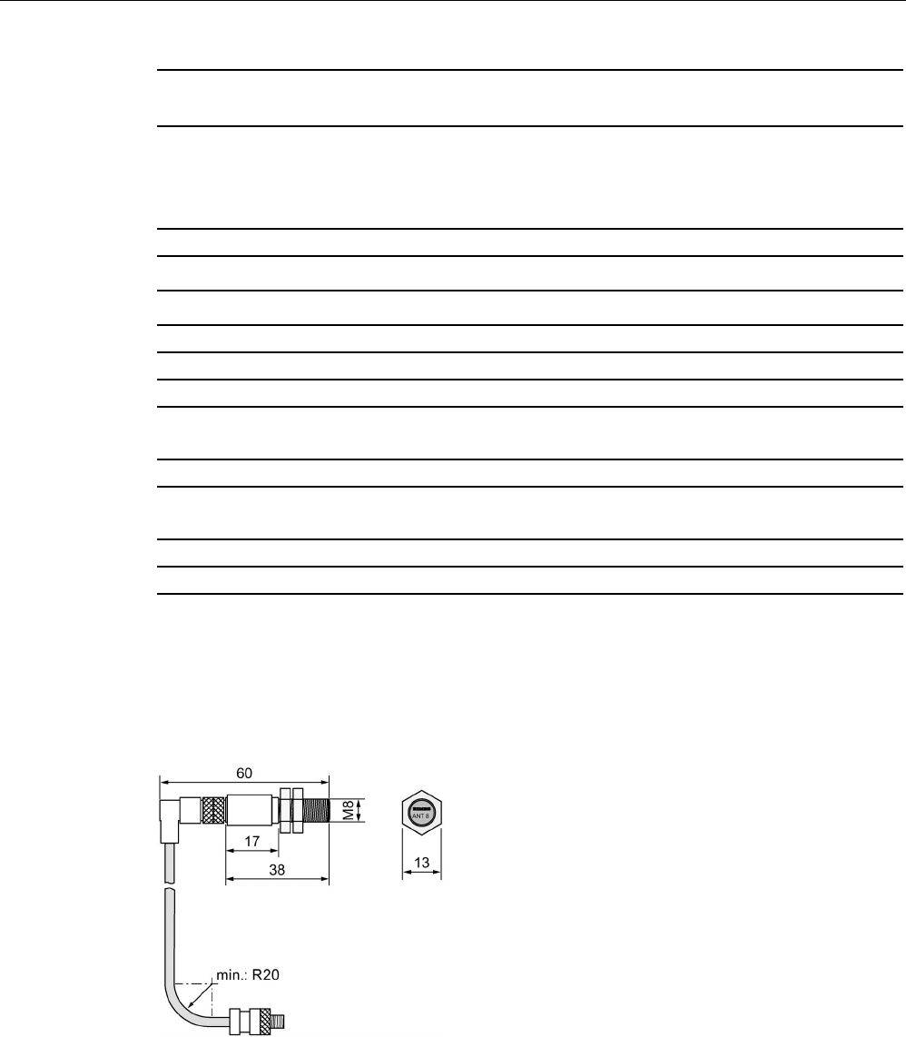
6.3.7
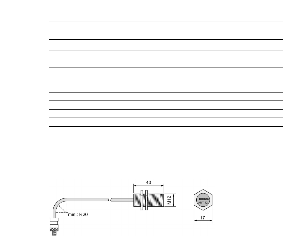
Dimension drawing
Figure 6-14 Dimension drawing ANT 8 (all values in mm)
Antennas
6.4 ANT 12
SIMATIC RF200
System Manual, 07/2017, J31069-D0227-U001-A9-7619 177
6.4
ANT 12
6.4.1
Features
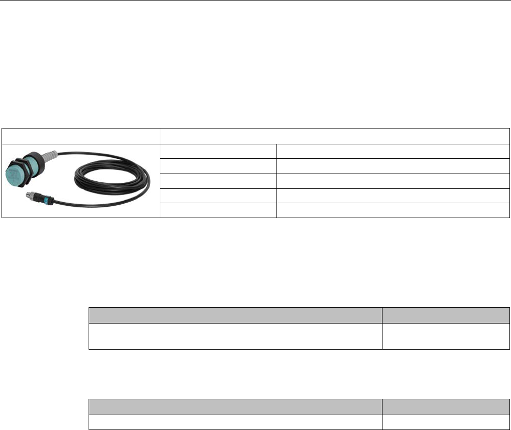
ANT 12
Characteristics
Area of application
Tool identification
Writing/reading distance up to 16 mm (depending on the transponder)
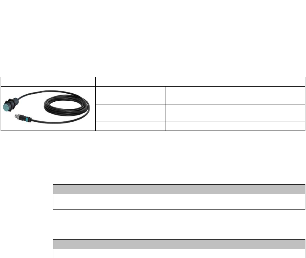
Connecting cable
3 m or 0.6 m
Connectable readers
RF250R
Degree of protection
IP67 (front)
6.4.2
Ordering data
Table 6- 12 Ordering data ANT 12
Antenna
Article number
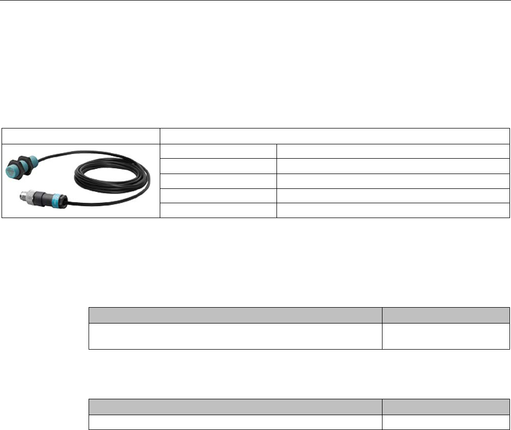
ANT 12
(including one plug-in antenna cable 3 m)
6GT2398-1CC00
Table 6- 13 Ordering data ANT 12 accessories
Accessories
Article number
Antenna cable, 3 m
6GT2398-0AH30
Antennas
6.4 ANT 12
SIMATIC RF200
178 System Manual, 07/2017, J31069-D0227-U001-A9-7619
6.4.3
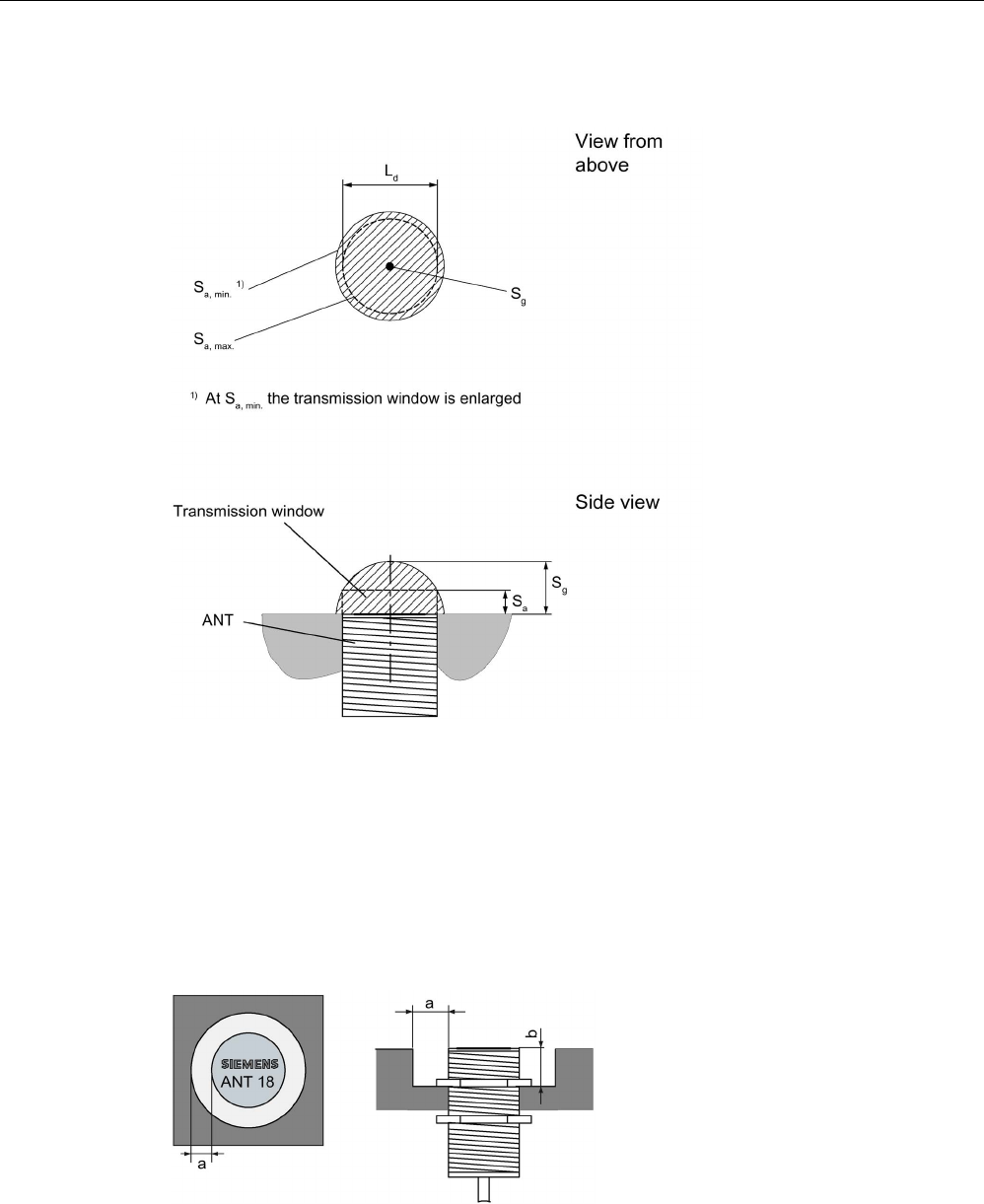
Transmission window
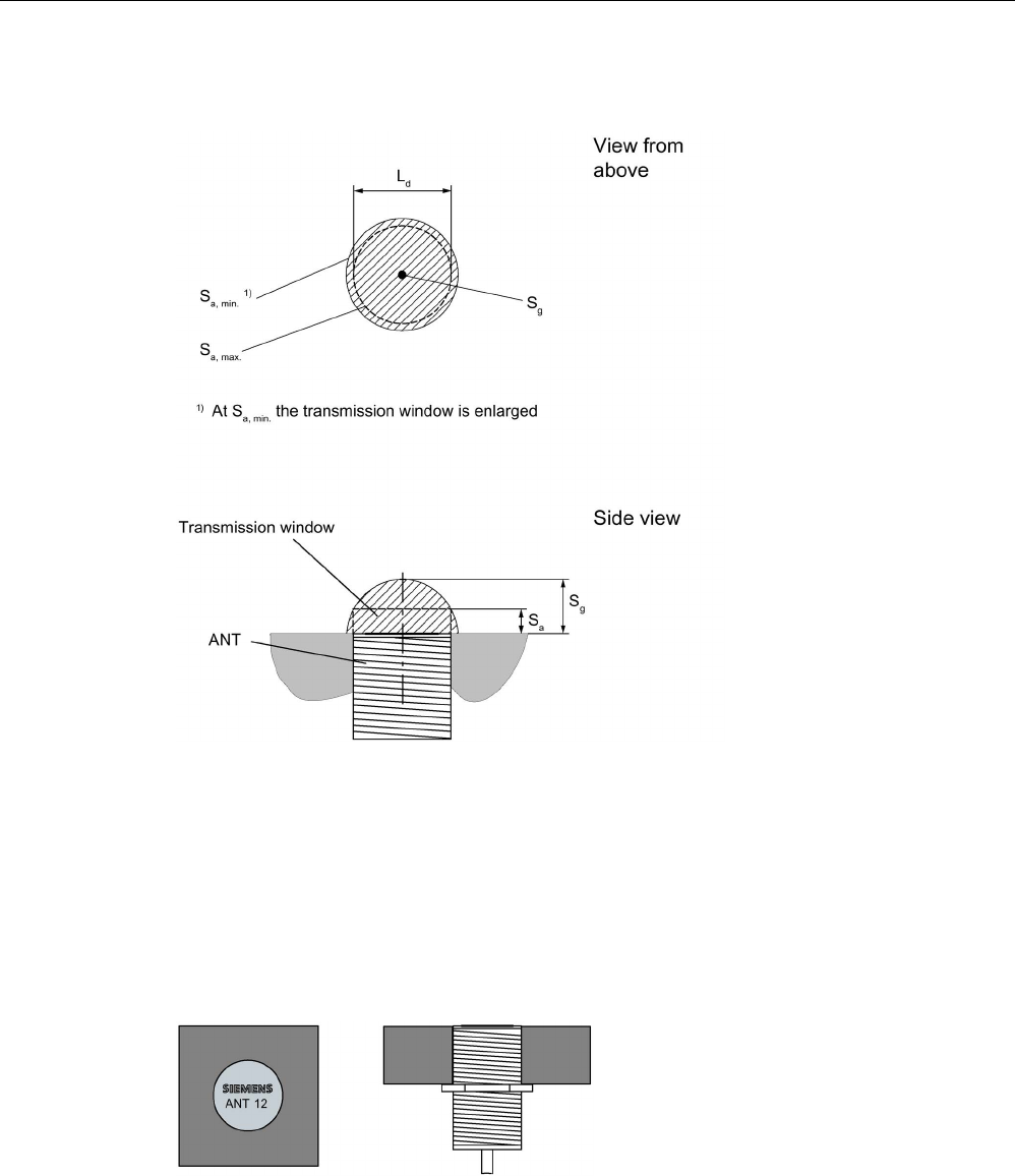
Ld
Length of the transmission window (= 20 mm)
Sa
Operating distance between antenna and transponder
Sg Limit distance (maximum clear distance between upper surface of the reader and the antenna,
at which the transmission can still function under normal conditions)
Figure 6-15 Transmission window ANT 12
6.4.4
Flush-mounted in metal
Figure 6-16 ANT 12 flush-mounted in metal
Antennas
6.4 ANT 12
SIMATIC RF200
System Manual, 07/2017, J31069-D0227-U001-A9-7619 179
6.4.5
Minimum spacing
Note
Extension of the data transmission time if distance values are undershot
If the distance values specified in the tables are undershot, it is possible that the inductive
fields will be affected. In
this case, the data transmission time can increase unpredictably or
a command is aborted with an error.
For this reason, please observe the values in the tables.
Minimum distances from transponder to transponder (without multitag mode)
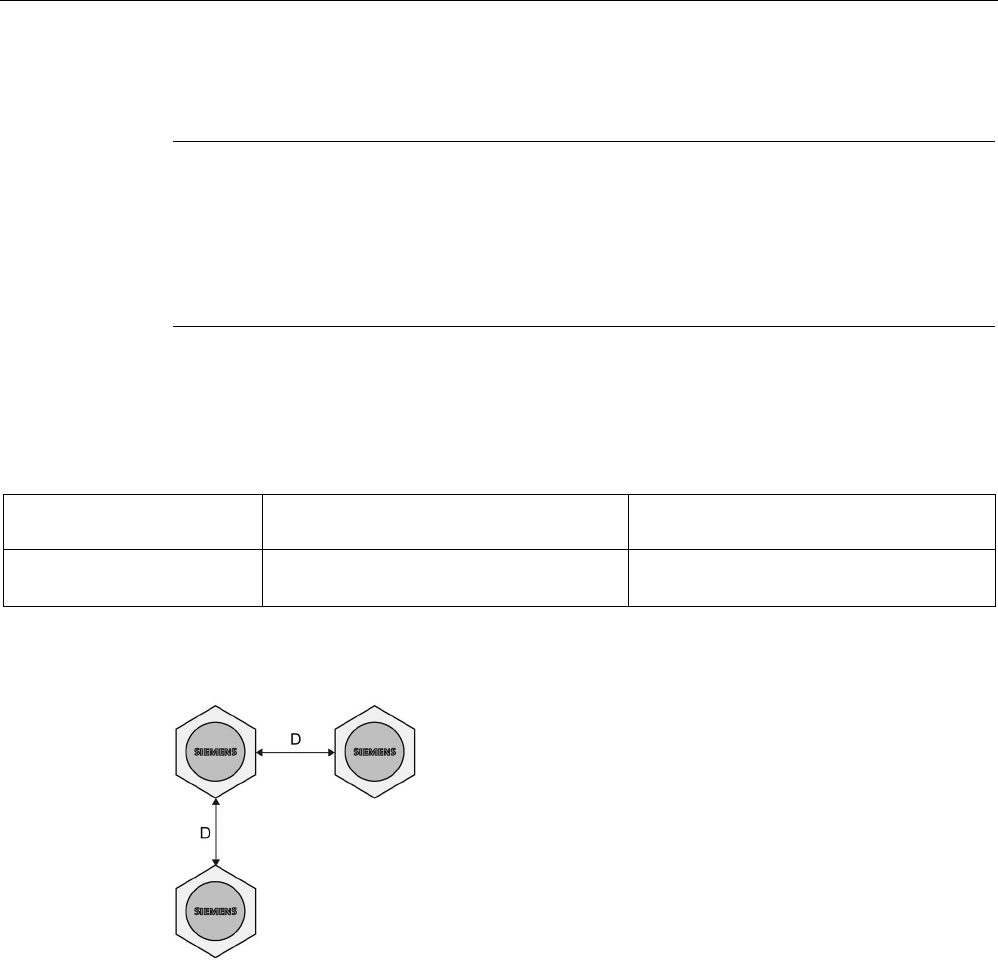
Table 6- 14 Minimum distances transponder edge to transponder edge
MDS D117 / MDS D127
MDS D421 / MDS D422 / MDS D428 / MDS
D460 / MDS D522 / MDS D528
RF250R with ANT 12
≥ 60 mm ≥ 80 mm
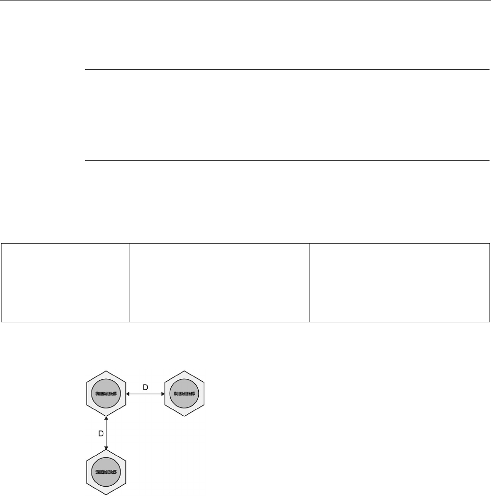
Definition of distance D
D
≥ 70 mm
Figure 6-17 Minimum distance for ANT 12
Antennas
6.4 ANT 12
SIMATIC RF200
180 System Manual, 07/2017, J31069-D0227-U001-A9-7619
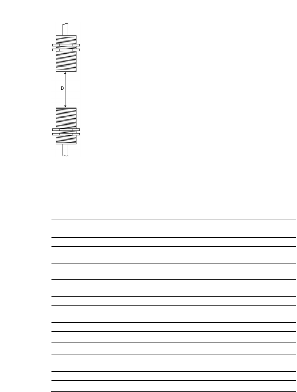
D
≥ 100 mm
Figure 6-18 Face-to-face distance between two ANT 12s
6.4.6
Technical data
6GT2398-1CC00
6GT2398-1CC10
Product type designation
ANT 12
Electrical data
Maximum write/read distance ANT ↔ transponder
(S
g
)
16 mm
Interfaces
Plug connection
4-pin (pin on antenna side)
Mechanical specifications
Housing
• Material • Plastic Crastin
• Color • Pale turquoise
Permitted ambient conditions
Ambient temperature
• During operation • -20 °C ... +70 °C
Antennas
6.4 ANT 12
SIMATIC RF200
System Manual, 07/2017, J31069-D0227-U001-A9-7619 181
6GT2398-1CC00
6GT2398-1CC10
• During transportation and storage • -40 °C ... +85 °C
Degree of protection to EN 60529
IP67 (front)
Shock according to EN 60721-3-7 Class 7 M3
1)
500 m/s
2
Vibration according to EN 60721-3-7 Class 7 M3
1)
200 m/s
2
Design, dimensions and weight
Dimensions (∅ x thread x L)
M12 x 1 x 40 mm
Weight
145 g
Type of mounting
2x plastic nuts M12 x 1
Cable length
3 m or 0.6 m
1)
Warning: The values for shock and vibration are maximum values and must not be applied contin-
uously.
6.4.7
Dimension drawing
Figure 6-19 Dimension drawing ANT 12 (all values in mm)
Antennas
6.5 ANT 18
SIMATIC RF200
182 System Manual, 07/2017, J31069-D0227-U001-A9-7619
6.5
ANT 18
6.5.1
Features
ANT 18
Characteristics
Area of application
Small assembly lines
Writing/reading distance up to 35 mm (depending on the transponder)
Connecting cable
3 m or 0.6 m
Connectable readers
RF250R
Degree of protection
IP67 (front)
6.5.2
Ordering data
Table 6- 15 Ordering data ANT 18
Antenna
Article number
ANT 18
(including one plug-in antenna cable 3 m)
6GT2398-1CA00
Table 6- 16 Ordering data ANT 18 accessories
Accessories
Article number
Antenna cable, 3 m
6GT2398-0AH30
Antennas
6.5 ANT 18
SIMATIC RF200
System Manual, 07/2017, J31069-D0227-U001-A9-7619 183
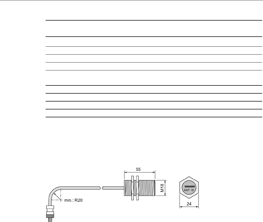
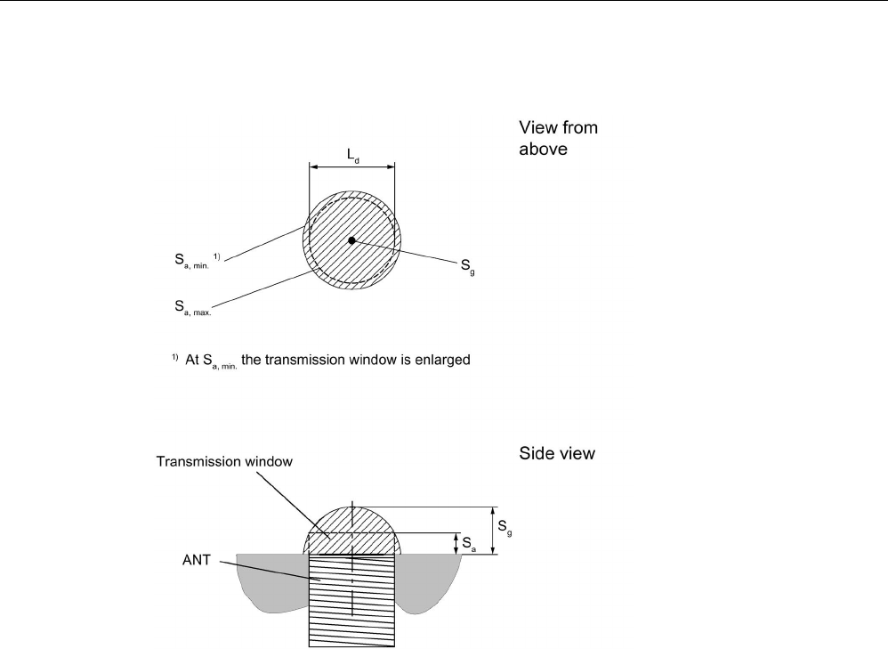
6.5.3
Transmission window
Ld
Length of the transmission window (= 30 mm)
Sa
Operating distance between antenna and transponder
Sg Limit distance (maximum clear distance between upper surface of the reader and the antenna,
at which the transmission can still function under normal conditions)
Figure 6-20 Transmission window ANT 18
6.5.4
Flush-mounted in metal
a
= 10 mm
b
= 10 mm
Figure 6-21 ANT 18 flush-mounted in metal
Antennas
6.5 ANT 18
SIMATIC RF200
184 System Manual, 07/2017, J31069-D0227-U001-A9-7619
6.5.5
Minimum spacing
Note
Extension of the data transmission time if distance values are undershot
If the distan
ce values specified in the tables are undershot, it is possible that the inductive
fields will be affected. In this case, the data transmission time can increase unpredictably or
a command is aborted with an error.
For this reason, please observe the value
s in the tables.
Minimum distances from transponder to transponder (without multitag mode)
Table 6- 17 Minimum distances transponder edge to transponder edge
MDS D124 / MDS D160 / MDS D324
MDS D421 / MDS D422 / MDS D423 /
MDS D424 / MDS D425 / MDS D428 /
MDS D460 / MDS D522 / MDS D524 /
MDS D528
RF250R with ANT 18
≥ 80 mm ≥ 100 mm
Definition of distance D
D
≥ 100 mm
Figure 6-22 Minimum distance for ANT 18

Antennas
6.5 ANT 18
SIMATIC RF200
System Manual, 07/2017, J31069-D0227-U001-A9-7619 185
D
≥ 100 mm
Figure 6-23 Face-to-face distance between two ANT 18s
6.5.6
Technical data
6GT2398-1CA00
6GT2398-1CA10
Product type designation
ANT 18
Electrical data
Maximum write/read distance ANT ↔ transponder
(S
g
)
35 mm
Interfaces
Plug connection
4-pin (pin on antenna side)
Mechanical specifications
Housing
• Material • Plastic Crastin
• Color • Pale turquoise
Permitted ambient conditions
Ambient temperature
• During operation • -20 °C ... +70 °C
Antennas
6.5 ANT 18
SIMATIC RF200
186 System Manual, 07/2017, J31069-D0227-U001-A9-7619
6GT2398-1CA00
6GT2398-1CA10
• During transportation and storage • -40 °C ... +85 °C
Degree of protection to EN 60529
IP67 (front)
Shock according to EN 60721-3-7 Class 7 M3
1)
500 m/s
2
Vibration according to EN 60721-3-7 Class 7 M3
1)
200 m/s
2
Design, dimensions and weight
Dimensions (∅ x thread x L)
M18 x 1 x 55 mm
Weight
130 g
Type of mounting
2x plastic nuts M18 x 1
Cable length
3 m or 0.6 m
1)
Warning: The values for shock and vibration are maximum values and must not be applied contin-
uously.
6.5.7
Dimension drawing
Figure 6-24 Dimension drawing ANT 18 (all values in mm)
Antennas
6.6 ANT 30
SIMATIC RF200
System Manual, 07/2017, J31069-D0227-U001-A9-7619 187
6.6
ANT 30
6.6.1
Features
ANT 18
Characteristics
Area of application
Small assembly lines
Writing/reading distance up to 55 mm (depending on the transponder)
Connecting cable
3 m
Connectable readers
RF250R
Degree of protection
IP67 (front)
6.6.2
Ordering data
Table 6- 18 Ordering data ANT 30
Antenna
Article number
ANT 30
(including one plug-in antenna cable 3 m)
6GT2398-1CD00
Table 6- 19 Ordering data ANT 30 accessories
Accessories
Article number
Antenna cable, 3 m
6GT2398-0AH30
Antennas
6.6 ANT 30
SIMATIC RF200
188 System Manual, 07/2017, J31069-D0227-U001-A9-7619
6.6.3
Transmission window
Ld
Length of the transmission window (= 60 mm)
Sa
Operating distance between antenna and transponder
Sg Limit distance (maximum clear distance between upper surface of the reader and the antenna,
at which the transmission can still function under normal conditions)
Figure 6-25 Transmission window ANT 30
Antennas
6.6 ANT 30
SIMATIC RF200
System Manual, 07/2017, J31069-D0227-U001-A9-7619 189
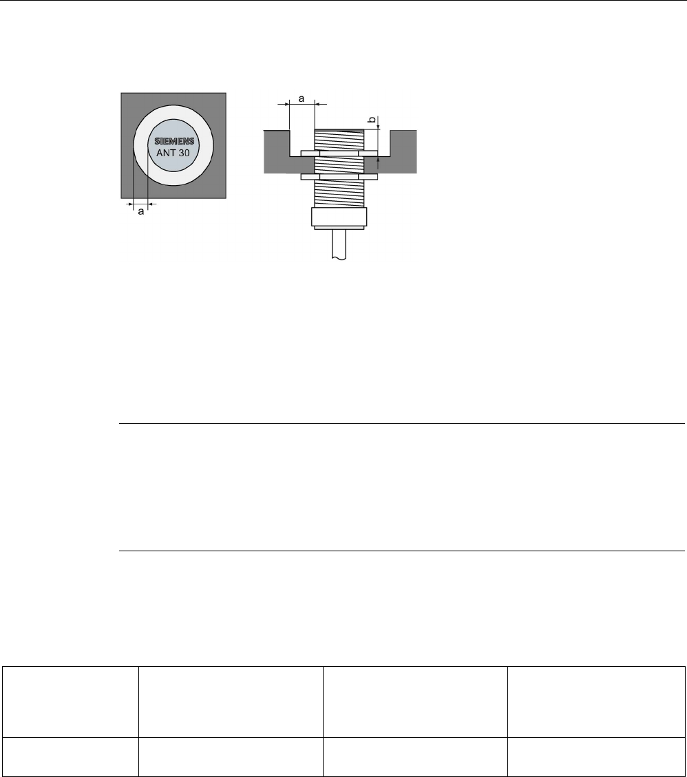
6.6.4
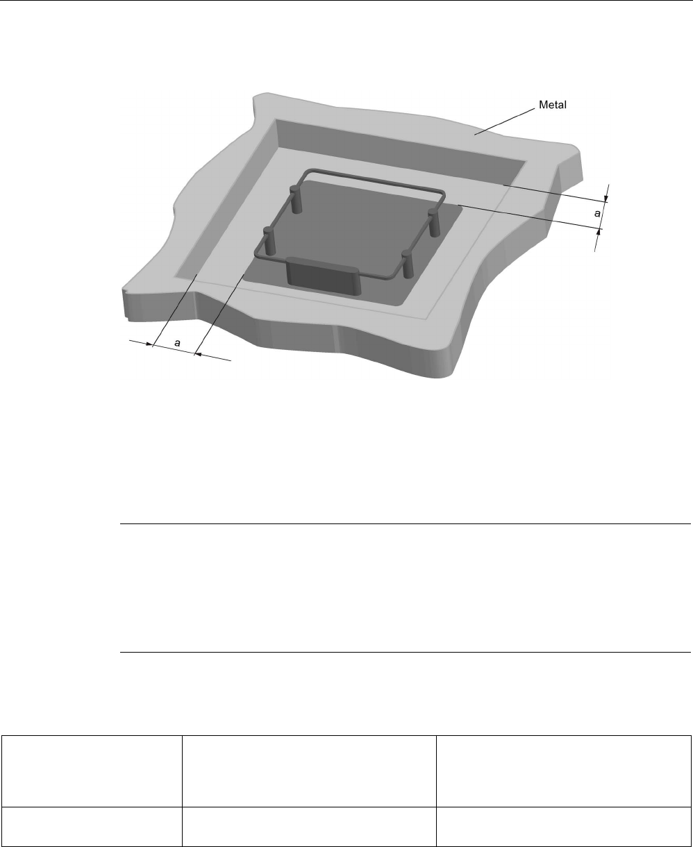
Flush-mounted in metal
a
= 20 mm
b
= 20 mm
Figure 6-26 ANT 30 flush-mounted in metal
6.6.5
Minimum spacing
Note
Extension of the data transmission time if distance values are undershot
If the distance values
specified in the tables are undershot, it is possible that the inductive
fields will be affected. In this case, the data transmission time can increase unpredictably or
a command is aborted with an error.
For this reason, please observe the values in the
tables.
Minimum distances from transponder to transponder (without multitag mode)
Table 6- 20 Minimum distances transponder edge to transponder edge
MDS D124 / MDS D160 /
MDS D324 / MDS D423 /
MDS D424 / MDS D460 /
MDS D524
MDS D422 / MDS D425 /
MDS D428 / MDS D522 /
MDS D528
MDS D126 / MDS D426 /
MDS D526
RF250R with ANT 30
≥ 100 mm ≥ 80 mm ≥ 150 mm
Antennas
6.6 ANT 30
SIMATIC RF200
190 System Manual, 07/2017, J31069-D0227-U001-A9-7619
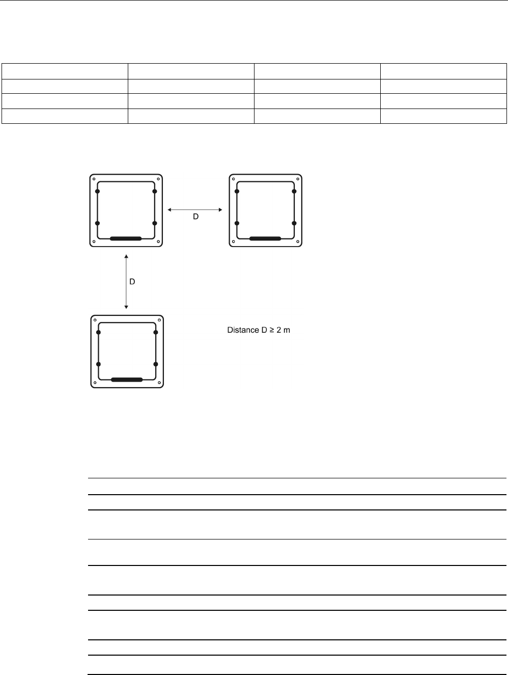
Definition of distance D
D
≥ 100 mm
Figure 6-27 Minimum distance for ANT 30
D
≥ 200 mm
Figure 6-28 Face-to-face distance between two ANT 30s
6.6.6
Technical data
6GT2398-1CD00
Product type designation
ANT 30
Electrical data
Maximum write/read distance ANT ↔ transponder
(S
g
)
60 mm
Antennas
6.6 ANT 30
SIMATIC RF200
System Manual, 07/2017, J31069-D0227-U001-A9-7619 191
6GT2398-1CD00
Interfaces
Plug connection
4-pin (pin on antenna side)
Mechanical specifications
Housing
• Material • Plastic Crastin
• Color • Pale turquoise
Permitted ambient conditions
Ambient temperature
• During operation • -20 °C ... +70 °C
• During transportation and storage • -40 °C ... +85 °C
Degree of protection to EN 60529
IP67 (front)
Shock according to EN 60721-3-7 Class 7 M3
1)
500 m/s
2
Vibration according to EN 60721-3-7 Class 7 M3
1)
200 m/s
2
Design, dimensions and weight
Dimensions (∅ x thread x L)
M30 x 1.5 x 61 mm
Weight
180 g
Type of mounting
2x plastic nuts M30 x 1.5
Cable length
3 m
1)
Warning: The values for shock and vibration are maximum values and must not be applied contin-
uously.
6.6.7
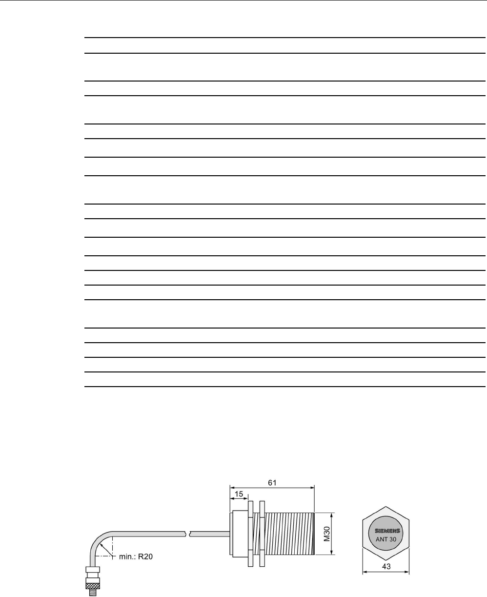
Dimension drawing
Figure 6-29 Dimension drawing ANT 30 (all values in mm)
Antennas
6.7 ANT D5
SIMATIC RF200
192 System Manual, 07/2017, J31069-D0227-U001-A9-7619
6.7
ANT D5
6.7.1
Features
ANT D5
Characteristics
Area of application
Storage, logistics and distribution
Writing/reading distance up to 500 mm (depending on the transponder)
Connecting cable
3.3 m
Readers that can be con-
nected
RF290R
Degree of protection IP65
6.7.2
Ordering data
Table 6- 21 Ordering data of ANT D5
Antenna
Article number
ANT D5
(incl. one antenna connecting cable 3.3 m)
6GT2698-5AA10
Table 6- 22 Ordering data of ANT D5 accessories
Accessories
Article number
Antenna splitter
(incl. one antenna connecting cable 3.3 m)
6GT2690-0AC00
Antenna multiplexer
(incl. one antenna connecting cable 0.4 m)
6GT2894-0EA00
Antenna cable
Length 3.3 m
6GT2691-0CH33
Length 10.5 m
6GT2691-0CN10
Antenna extension cable, length 7.2 m
6GT2691-0DH72
Antennas
6.7 ANT D5
SIMATIC RF200
System Manual, 07/2017, J31069-D0227-U001-A9-7619 193
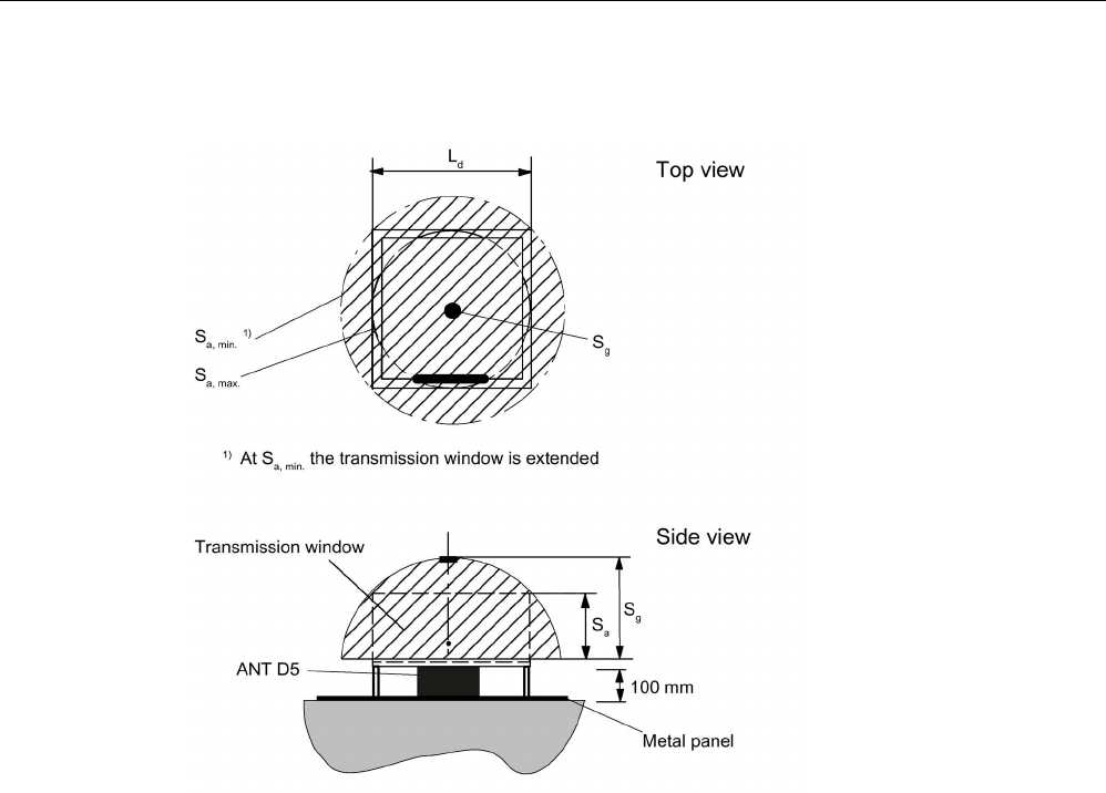
6.7.3
Transmission window
Ld
Length of the transmission window (= 300 mm)
Sa
Operating distance between antenna and transponder
Sg Limit distance (maximum clear distance between upper surface of the reader and the antenna,
at which the transmission can still function under normal conditions)
Figure 6-30 Transmission window for ANT D5
Antennas
6.7 ANT D5
SIMATIC RF200
194 System Manual, 07/2017, J31069-D0227-U001-A9-7619
6.7.4
Flush-mounted in metal
a
= 150 mm
Figure 6-31 Metal-free area for ANT D5
6.7.5
Minimum spacing
Note
Extension of the data transmission time if distance values are undershot
If the distanc
e values specified in the tables are undershot, it is possible that the inductive
fields will be affected. In this case, the data transmission time can increase unpredictably or
a command is aborted with an error.
For this reason, please observe the values
in the tables.
Minimum distances from transponder to transponder (without multitag mode)
MDS D100 / MDS D126 / MDS D139 /
MDS D165 / MDS D200 / MDS D261 /
MDS D339 / MDS D400 / MDS D426 /
MDS D526
MDS D124 / MDS D160 / MDS D324 /
MDS D424 / MDS D428 / MDS D460 /
MDS D524 / MDS D528 / MDS D560
RF290R
≥ 1 m ≥ 0.8 m
Antennas
6.7 ANT D5
SIMATIC RF200
System Manual, 07/2017, J31069-D0227-U001-A9-7619 195
Minimum distances from antenna to antenna
RF290R with ANT D5
RF290R with ANT D6
RF290R with ANT D10
RF290R with ANT D5
≥ 2 m
≥ 2 m
≥ 2 m
RF290R with ANT D6
≥ 2 m ≥ 2 m ≥ 2 m
RF290R with ANT D10
≥ 2 m
≥ 2 m
≥ 2 m
Definition of distance D
Figure 6-32 Distance D: ANT D5
6.7.6
Technical data
6GT2698-5AA10
Product type designation
ANT D5
Electrical data
Maximum write/read distance ANT ↔ transponder
(S
g
)
500 mm
Interfaces
Plug connection
1-pin TNC plug
Mechanical specifications
Housing
• Material • Aluminum/plastic

Antennas
6.7 ANT D5
SIMATIC RF200
196 System Manual, 07/2017, J31069-D0227-U001-A9-7619
6GT2698-5AA10
• Color • gray/black
Permitted ambient conditions
Ambient temperature
• During operation • -20 °C ... +55 °C
• During transportation and storage • -25 ℃ ... +70 ℃
Degree of protection to EN 60529
IP65 (UL: for indoor use only)
Shock according to EN 60721-3-7 Class 7 M3
1)
300 m/s
2
Vibration according to EN 60721-3-7 Class 7 M31)
• 10 m/s2 (9 ... 200 Hz)
• 15 m/s2 (200 ... 500 Hz)
Design, dimensions and weight
Dimensions (L x W x H)
380 x 380 x 110 mm
Weight
1.2 kg
Type of mounting
4x M6 or alternatively M8 screws
Cable length
3.3 m
1)
Warning: The values for shock and vibration are maximum values and must not be applied contin-
uously.
Antennas
6.7 ANT D5
SIMATIC RF200
System Manual, 07/2017, J31069-D0227-U001-A9-7619 197
6.7.7
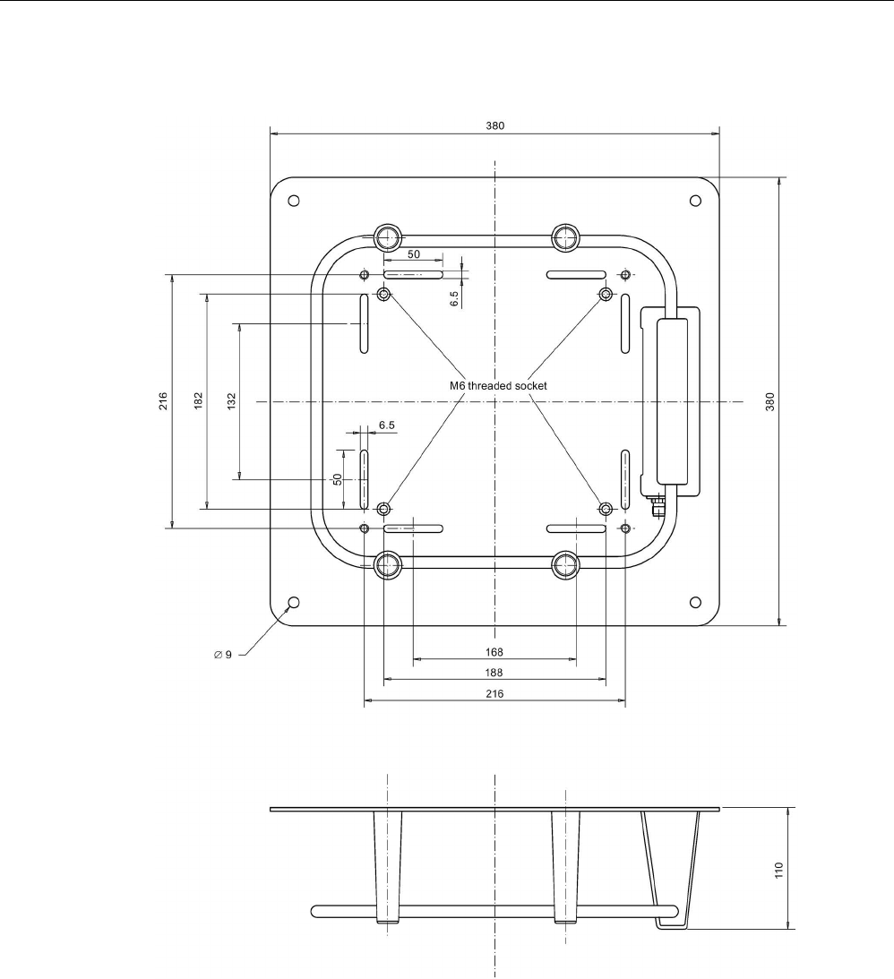
Dimension drawing
Figure 6-33 Dimension drawing for ANT D5
Antennas
6.8 ANT D6
SIMATIC RF200
198 System Manual, 07/2017, J31069-D0227-U001-A9-7619
6.8
ANT D6
6.8.1
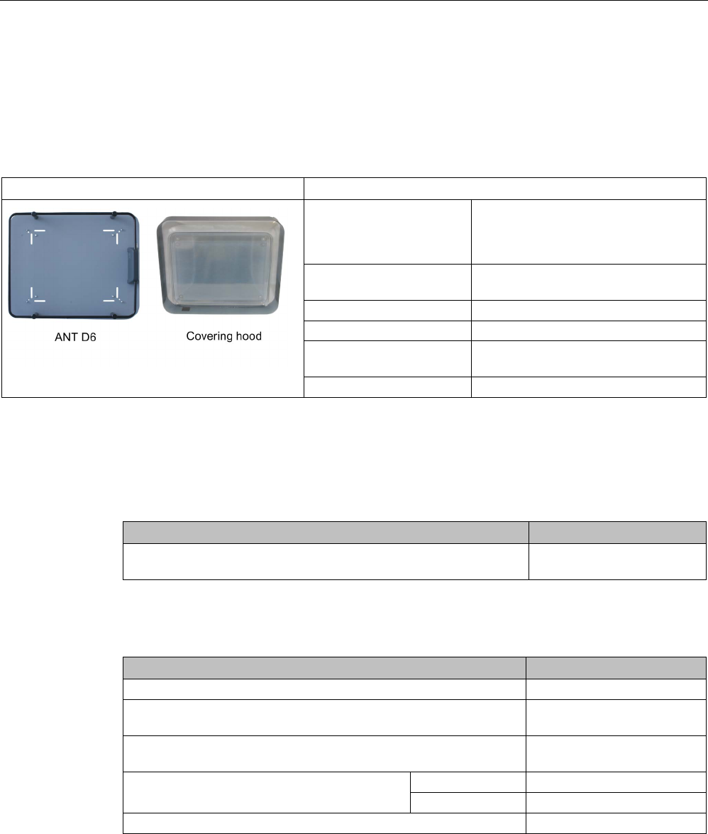
Features
ANT D6
Characteristics
Area of application • Storage, logistics and distribution
• Suitable for high-speed applications
with large writing/reading distance
Writing/reading distance up to 650 mm (depending on the tran-
sponder)
Connecting cable
3.3 m; included in scope of supply
Cover
Available as accessory
Readers that can be con-
nected
RF290R
Degree of protection
IP65 (also without cover)
6.8.2
Ordering data
Table 6- 23 ANT D6 ordering data
Antenna
Article number
ANT D6
(without cover, incl. one antenna connecting cable 3.3 m)
6GT2698-5AB00
Table 6- 24 Ordering data for ANT D6 accessories
Accessories
Article number
Covering hood for ANT D6
6GT2690-0AD00
Antenna splitter
(incl. one antenna connecting cable 3.3 m)
6GT2690-0AC00
Antenna multiplexer
(incl. one antenna connecting cable 0.4 m)
6GT2894-0EA00
Antenna cable
Length 3.3 m
6GT2691-0CH33
Length 10.5 m
6GT2691-0CN10
Antenna extension cable, length 7.2 m
6GT2691-0DH72
Antennas
6.8 ANT D6
SIMATIC RF200
System Manual, 07/2017, J31069-D0227-U001-A9-7619 199
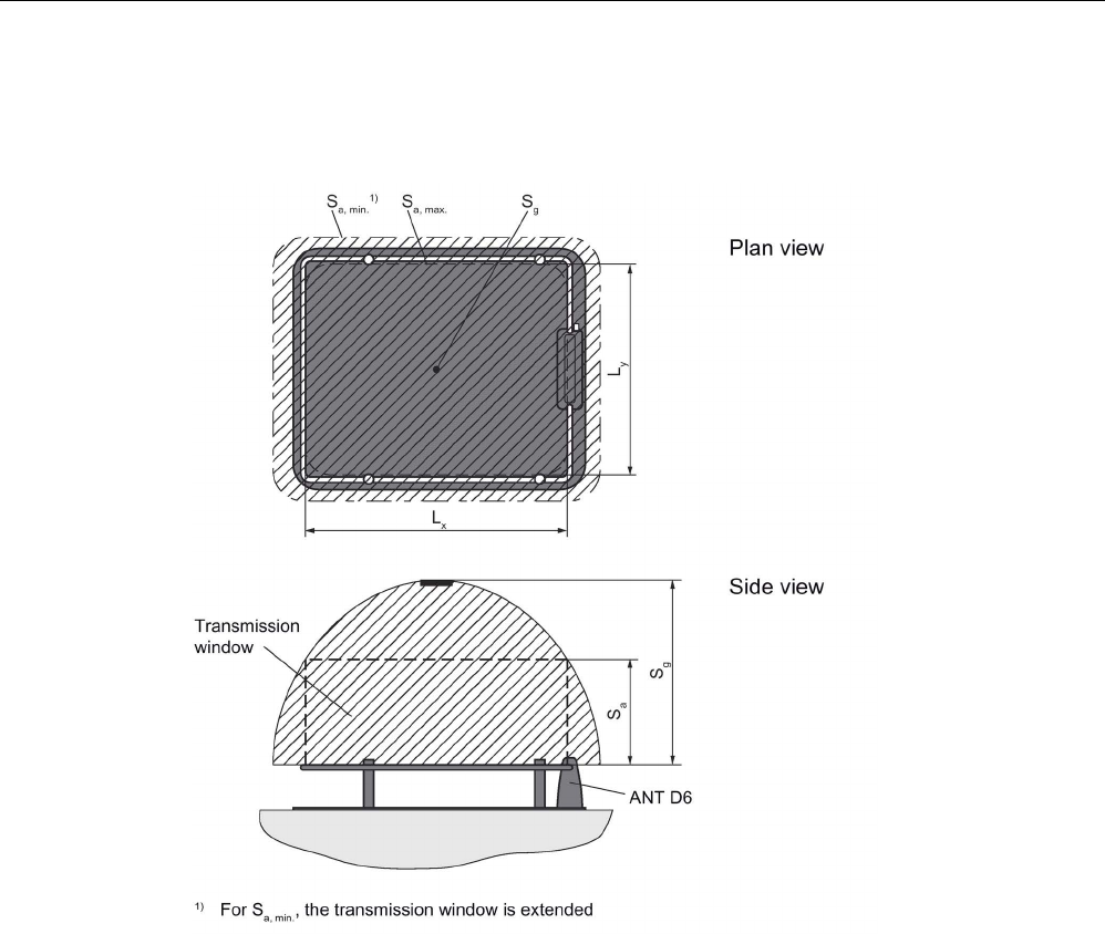
6.8.3
Transmission window
Lx
= 520 mm
Ly
= 420 mm
Figure 6-34 Transmission window for ANT D6
Antennas
6.8 ANT D6
SIMATIC RF200
200 System Manual, 07/2017, J31069-D0227-U001-A9-7619
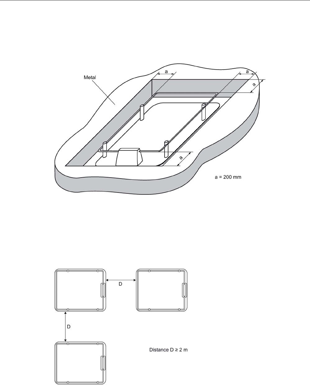
6.8.4
Metal-free area
Flush-mounted in metal
Figure 6-35 Metal-free area for ANT D6
6.8.5
Minimum spacing
Definition of distance D
Figure 6-36 Distance D: ANT D6

Antennas
6.8 ANT D6
SIMATIC RF200
System Manual, 07/2017, J31069-D0227-U001-A9-7619 201
6.8.6
Technical data
6GT2698-5AB00
Product type designation
ANT D6
Electrical data
Maximum write/read distance ANT ↔ transponder
(S
g
)
650 mm
Interfaces
Plug connection
1-pin TNC plug
Mechanical specifications
Housing
• Material • Aluminum/plastic
• Color • gray/black
Permitted ambient conditions
Ambient temperature
• During operation • -20 °C ... +55 °C
• During transportation and storage • -25 ℃ ... +70 ℃
Degree of protection to EN 60529
IP65 (UL: for indoor use only)
Shock according to EN 60721-3-7 Class 7 M3
1)
300 m/s
2
Vibration according to EN 60721-3-7 Class 7 M31)
• 10 m/s2 (9 ... 200 Hz)
• 15 m/s2 (200 ... 500 Hz)
Design, dimensions and weight
Dimensions (L x W x H)
580 x 480 x 110 mm
Weight 3.3 kg
(without cover)
Antennas
6.8 ANT D6
SIMATIC RF200
202 System Manual, 07/2017, J31069-D0227-U001-A9-7619
6GT2698-5AB00
Type of mounting
4 x M6 screws
Cable length
3.3 m
1)
Warning: The values for shock and vibration are maximum values and must not be applied contin-
uously.
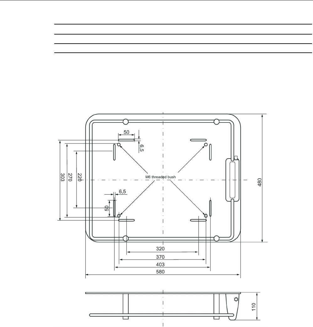
6.8.7
Dimensional diagram
Figure 6-37 Dimension drawing for ANT D6
Antennas
6.9 ANT D10
SIMATIC RF200
System Manual, 07/2017, J31069-D0227-U001-A9-7619 203
6.9
ANT D10
6.9.1
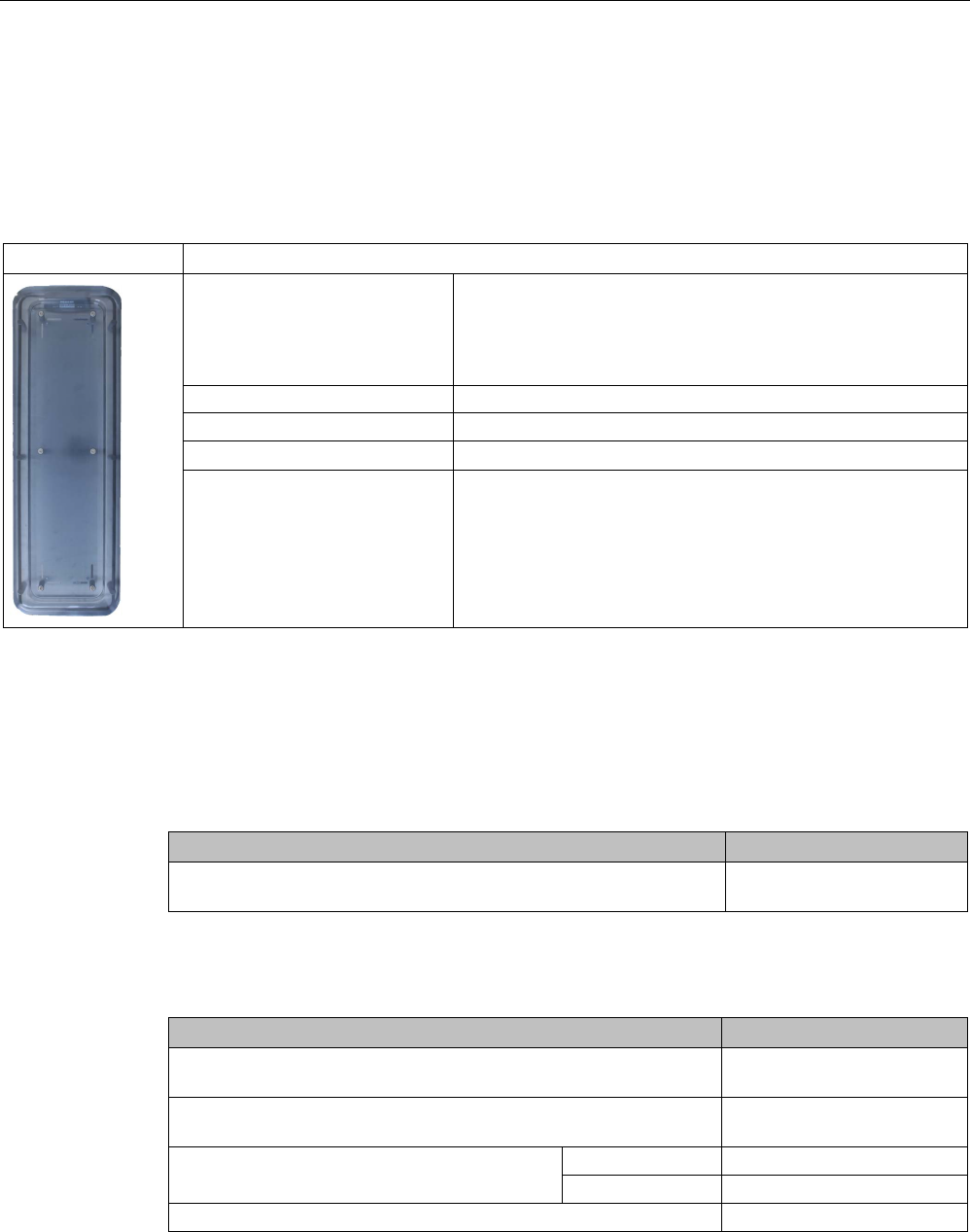
Features
ANT D10
Characteristics
Area of application • Storage, logistics and distribution, e.g. clothing industry,
laundries
• Particularly when small MDS are used (e.g. MDS D124,
MDS D160) and when there is a long transmission field
Writing/reading distance
up to 480 mm (depending on the transponder)
Connecting cable
3.3 m; included in scope of supply
Cover Included in scope of supply
Readers that can be connected
RF290R
6.9.2
Ordering data
Table 6- 25 Ordering data of ANT D10
Antenna
Article number
ANT D10
(incl. cover and one antenna connecting cable 3.3 m)
6GT2698-5AF00
Table 6- 26 Ordering data of ANT D10 accessories
Accessories
Article number
Antenna splitter
(incl. one antenna connecting cable 3.3 m)
6GT2690-0AC00
Antenna multiplexer
(incl. one antenna connecting cable 0.4 m)
6GT2894-0EA00
Antenna cable
Length 3.3 m
6GT2691-0CH33
Length 10.5 m
6GT2691-0CN10
Antenna extension cable, length 7.2 m
6GT2691-0DH72
Antennas
6.9 ANT D10
SIMATIC RF200
204 System Manual, 07/2017, J31069-D0227-U001-A9-7619
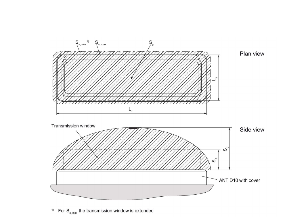
6.9.3
Transmission window
Lx
1050 mm
Ly
350 mm
Figure 6-38 Transmission window for ANT D10
Antennas
6.9 ANT D10
SIMATIC RF200
System Manual, 07/2017, J31069-D0227-U001-A9-7619 205
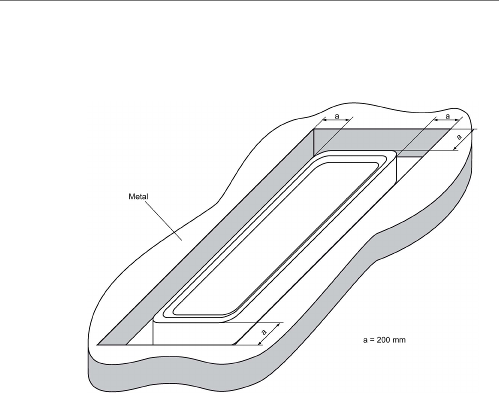
6.9.4
Metal-free area
Flush-mounted in metal
Figure 6-39 Metal-free area for ANT D10
Antennas
6.9 ANT D10
SIMATIC RF200
206 System Manual, 07/2017, J31069-D0227-U001-A9-7619
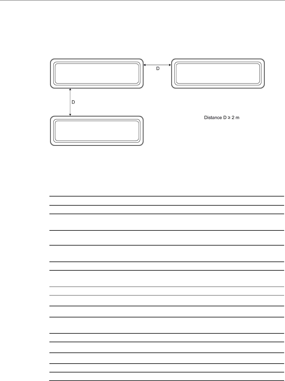
6.9.5
Minimum spacing
Definition of distance D
Figure 6-40 Distance D: ANT D10
6.9.6
Technical data
6GT2698-5AF00
Product type designation
ANT D10
Electrical data
Maximum write/read distance ANT ↔ transponder
(S
g
)
480 mm
Interfaces
Plug connection
1-pin TNC plug
Mechanical specifications
Housing
• Material • Aluminum/plastic
• Color • gray/black
Permitted ambient conditions
Ambient temperature
• During operation • -20 °C ... +55 °C
• During transportation and storage • -25 ℃ ... +70 ℃
Degree of protection to EN 60529
IP65 (UL: for indoor use only)
Shock according to EN 60721-3-7 Class 7 M3
1)
300 m/s
2

Antennas
6.9 ANT D10
SIMATIC RF200
System Manual, 07/2017, J31069-D0227-U001-A9-7619 207
6GT2698-5AF00
Vibration according to EN 60721-3-7 Class 7 M31) • 10 m/s2 (9 ... 200 Hz)
• 15 m/s2 (200 ... 500 Hz)
Design, dimensions and weight
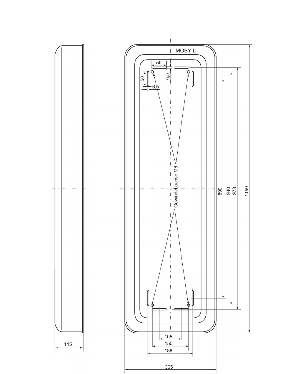
Dimensions (L x W x H) 1150 x 365 x 115 mm
(with cover)
Weight
10 kg
Type of mounting
4 x M6 screws
Cable length
3.3 m
1)
Warning: The values for shock and vibration are maximum values and must not be applied contin-
uously.
Antennas
6.9 ANT D10
SIMATIC RF200
208 System Manual, 07/2017, J31069-D0227-U001-A9-7619
6.9.7
Dimensional diagram
Figure 6-41 Dimension drawing for ANT D10
SIMATIC RF200
System Manual, 07/2017, J31069-D0227-U001-A9-7619 209
Transponder
7
7.1
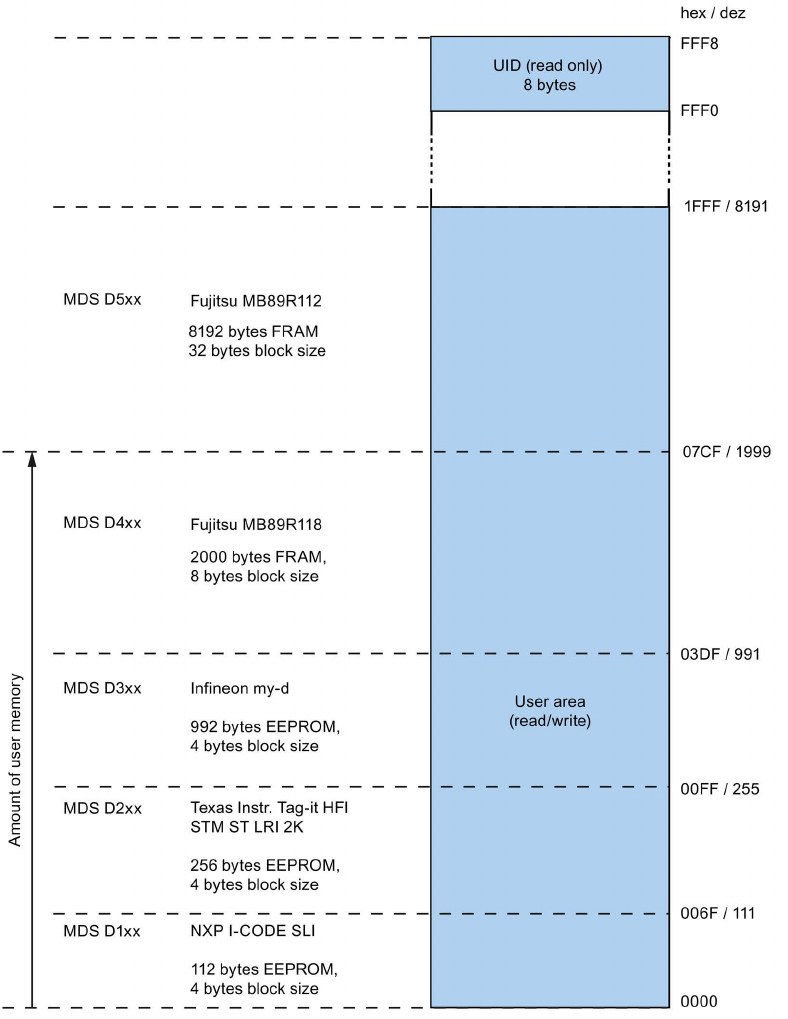
Memory configuration of ISO the transponders
Figure 7-1 Memory configuration of ISO the transponders
Transponder
7.2 MDS D100
SIMATIC RF200
210 System Manual, 07/2017, J31069-D0227-U001-A9-7619
Memory areas
Depending on the manufacturer of the transponder chip, the memory configuration of an ISO
transponder consists of varying sizes of user memory.
The typical sizes are 112 bytes, 256 bytes, 992 bytes EEPROM or 2000 bytes, 8192 bytes
FRAM. Each ISO transponder chip has an 8-byte long unique serial number (UID, read
only). This UID is transferred as an 8 byte value through a read command to address FFF0
with a length of 8.
Note
OPT memory
The transponders have an OTP memory. This was previously only supported by the RF300
readers.
7.2
MDS D100
7.2.1
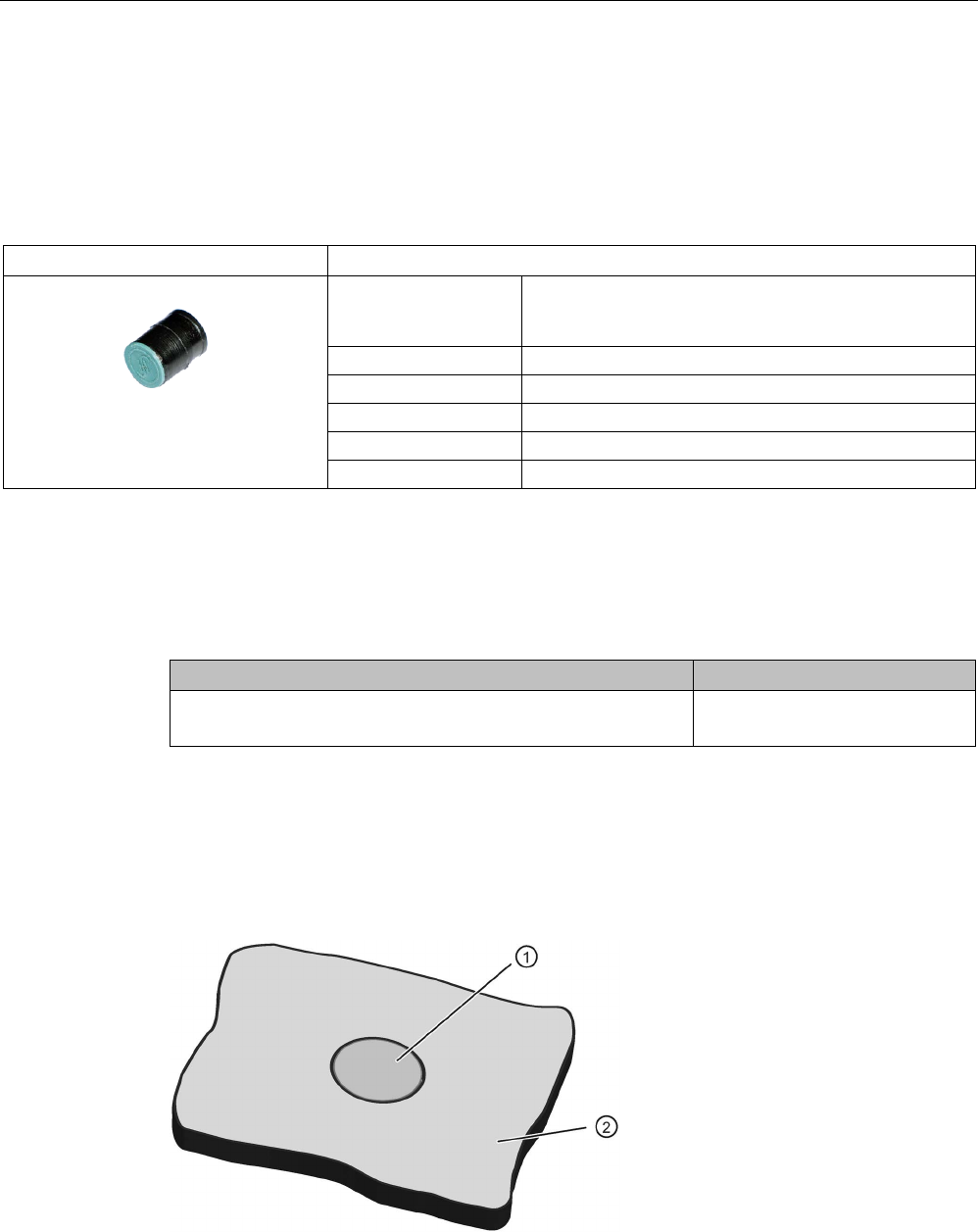
Characteristics
MDS D100
Characteristics
Area of application From simple identification such as electronic
barcode replacement/supplementation, through
warehouse and distribution logistics, right up to
product identification.
Memory size
112 bytes of EEPROM user memory
Write/read range
See section Field data (Page 39).
Mounting on metal
Yes, with spacer
ISO standard
ISO 15693
Degree of protection
IP68
7.2.2
Ordering data
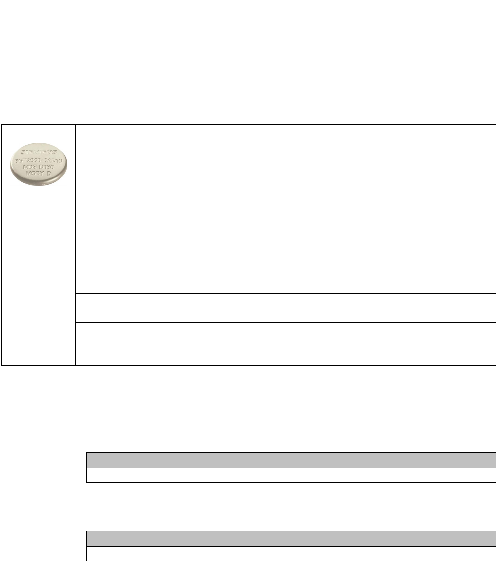
Table 7- 1 Ordering data for MDS D100
Article number
MDS D100
6GT2600-0AD10
Transponder
7.2 MDS D100
SIMATIC RF200
System Manual, 07/2017, J31069-D0227-U001-A9-7619 211
Table 7- 2 Ordering data for MDS D100 accessory
Article number
Spacer
(in conjunction with fixing pocket 6GT2190-0AB00)
6GT2190-0AA00
Fixing pocket
(in conjunction with spacer 6GT2190-0AA00)
6GT2190-0AB00
Fixing pocket
(not suitable for fixing directly onto metal)
6GT2390-0AA00
7.2.3
Metal-free area
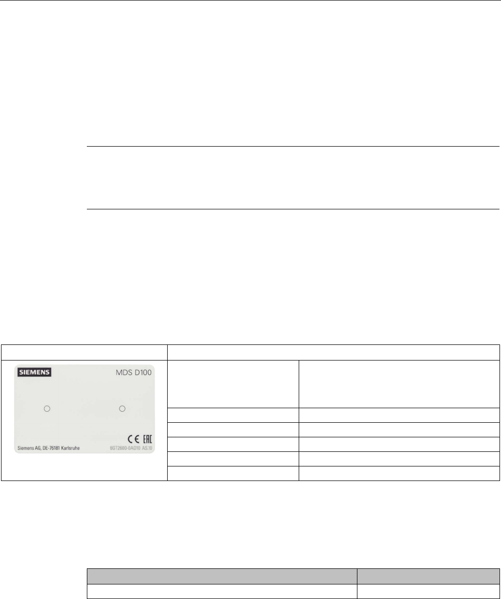
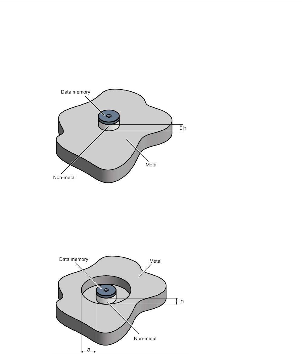
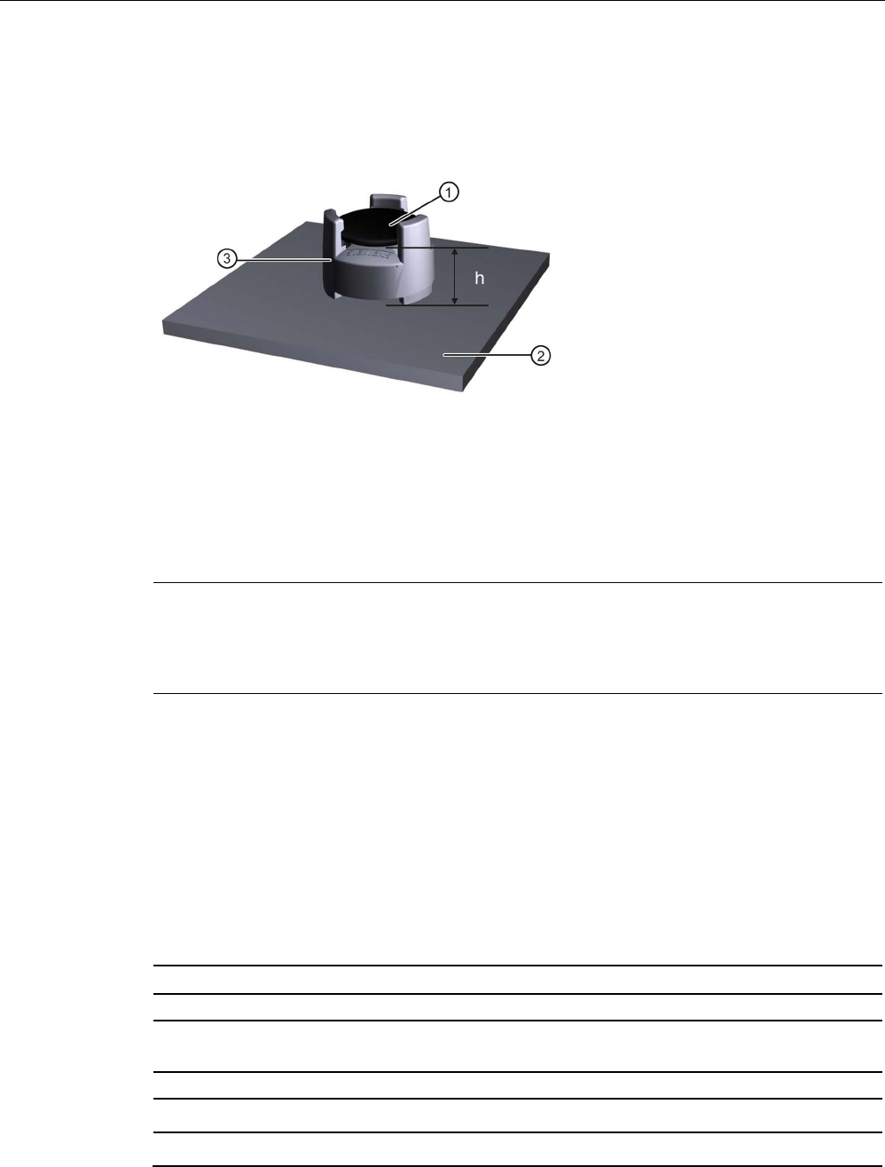
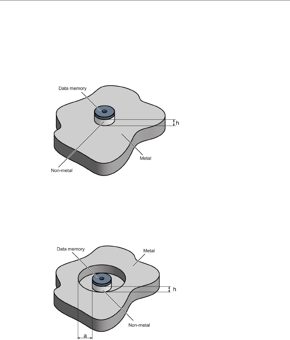
Direct mounting of the MDS D100 on metal is not allowed. A distance of ≥ 20 mm is
recommended. This can be achieved using the spacer 6GT2190-0AA00 in combination with
the fixing pocket 6GT2190-0AB00.
Mounting on metal
h
≥ 20 mm
①
Transponder
②
Metal
③
Non-metal
Figure 7-2 Mounting of the MDS D100 on metal with spacer
Transponder
7.2 MDS D100
SIMATIC RF200
212 System Manual, 07/2017, J31069-D0227-U001-A9-7619
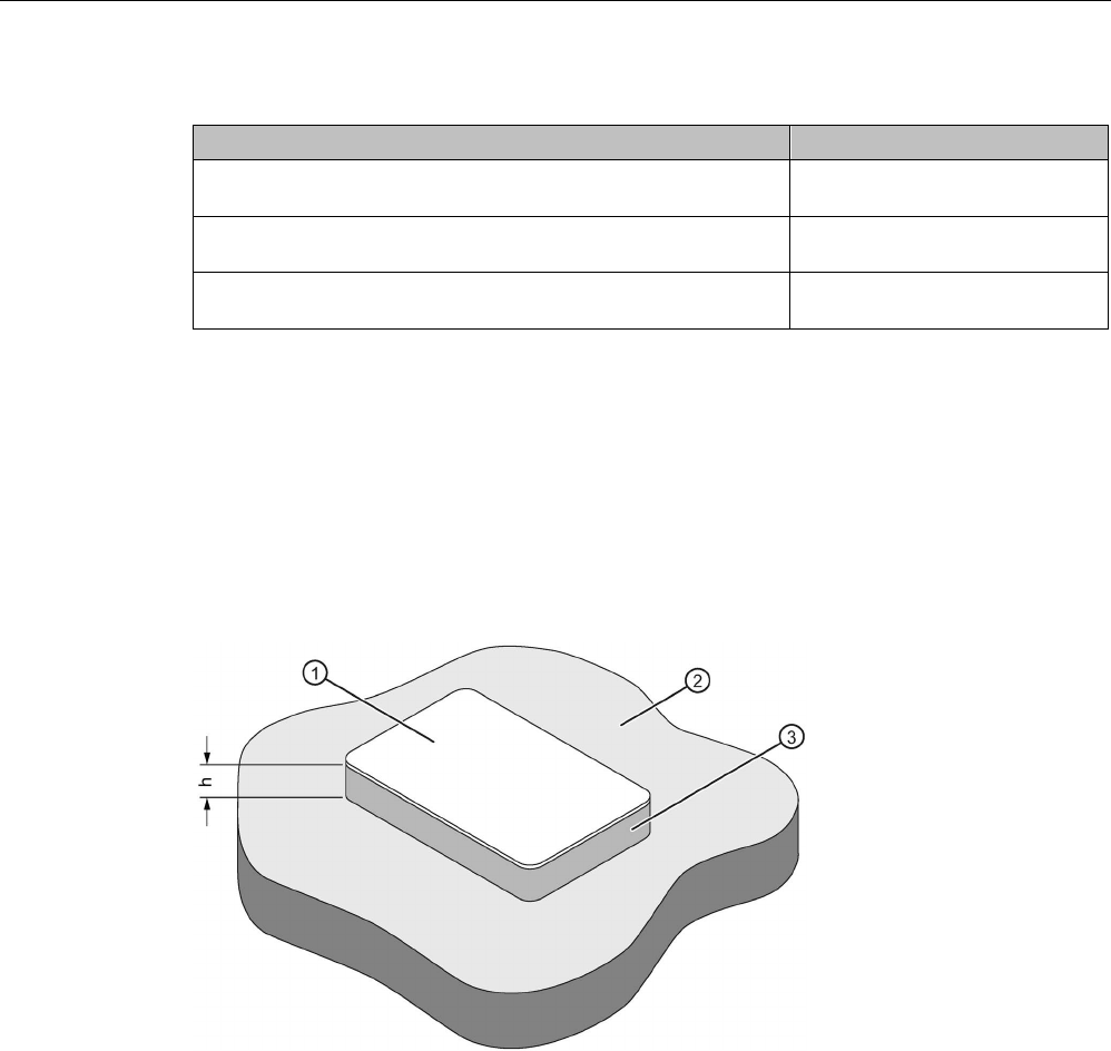
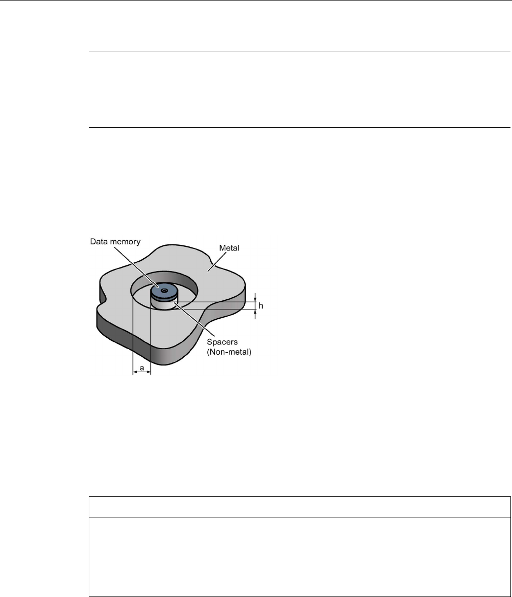
Flush-mounting
a
≥ 20 mm
h
≥ 20 mm
①
Transponder
②
Metal
③
Non-metal
Figure 7-3 Flush-mounting of MDS D100 in metal with spacer
Note
If the minim
um guide values (h or a) are not observed, a reduction of the field data results.
7.2.4
Technical data
Table 7- 3 Technical specifications for MDS D100
6GT2600-0AD10
Product type designation
SIMATIC MDS D100
Memory
Memory configuration
• UID • 8 bytes
• User memory • 112 bytes EEPROM
• OTP memory • 16 bytes (EEPROM)

Transponder
7.2 MDS D100
SIMATIC RF200
System Manual, 07/2017, J31069-D0227-U001-A9-7619 213
6GT2600-0AD10
Read cycles (at < 40 ℃)
> 10
14
Write cycles (at < 40 ℃)
> 10
6
Data retention time (at < 40 ℃)
> 10 years
Write/read distance (Sg) Dependent on the reader used, see section "Field
data (Page 39)"
MTBF (Mean Time Between Failures)
228 years
Mechanical specifications
Housing
• Material • PET
• Color • White/black
Recommended distance to metal
≥ 20 mm
Power supply
Inductive, without battery
Permitted ambient conditions
Ambient temperature
• during write/read access • -25 to +80 ℃
• outside the read/write field • -25 to +80 ℃
• during storage • -25 to +80 ℃
Degree of protection to EN 60529
IP68
Shock-resistant to EN 60721-3-7 class 7M3
ISO 10373 / ISO 7810
1)
Vibration-resistant to EN 60721-3-7, class 7M3
ISO 10373 / ISO 7810
1)
Torsion and bending load
ISO 10373/ISO 7816-1
Design, dimensions and weight
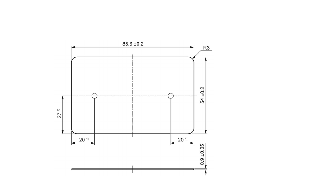
Dimensions (L x W x H) 85.6 x 54 x 0.9 mm
Weight 5 g
Type of mounting • Fixing pocket
• Glued 2)
1)
The values for shock and vibration are maximum values and must not be applied continuously.
2) The processing instructions of the adhesive manufacturer must be observed.
Transponder
7.2 MDS D100
SIMATIC RF200
214 System Manual, 07/2017, J31069-D0227-U001-A9-7619
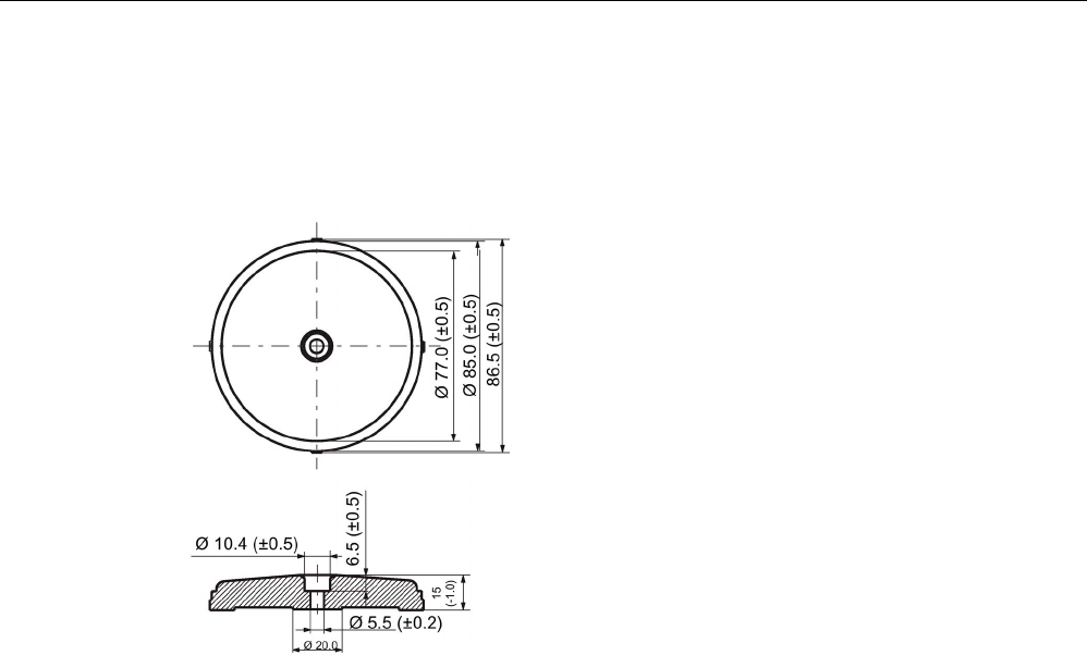
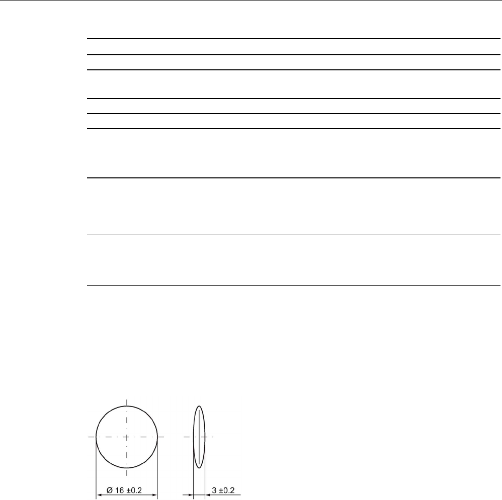
7.2.5
Dimension drawing
Dimensions in mm
1)
Dimensions for mounting holes
Figure 7-4 MDS D100 dimension drawing
Transponder
7.3 MDS D117
SIMATIC RF200
System Manual, 07/2017, J31069-D0227-U001-A9-7619 215
7.3
MDS D117
7.3.1
Features
MDS D117
Characteristics
Area of application Very compact data carrier that can be cemented into
objects where precise positioning is necessary;
e.g. tool identification, workpiece holders etc..
Memory size 112 bytes of EEPROM user memory
Write/read range
See section "Field data (Page 39)."
Mounting in metal
Yes, flush-mounted in metal
ISO standard
ISO 15693
Degree of protection
IP68/IPx9K
7.3.2
Ordering data
Table 7- 4 Ordering data for MDS D117
Article number
MDS D117
Pack of 10
6GT2600-0AG00
7.3.3
Mounting in metal
Flush-mounted in metal
①
Transponder
②
Metal

Transponder
7.3 MDS D117
SIMATIC RF200
216 System Manual, 07/2017, J31069-D0227-U001-A9-7619
7.3.4
Technical specifications
Table 7- 5 Technical specifications for MDS D117
6GT2600-0AG00
Product type designation
SIMATIC MDS D117
Memory
Memory configuration
• UID • 8 bytes
• User memory • 112 bytes EEPROM
• OTP memory • 16 bytes (EEPROM)
Read cycles (at < 40 ℃)
> 10
14
Write cycles (at < 40 ℃)
> 10
6
Data retention time (at < 40 ℃)
> 10 years
Write/read distance (Sg) Dependent on the reader used, see section "Field
data (Page 39)"
MTBF (Mean Time Between Failures)
228 years
Mechanical specifications
Housing
• Material • PPS
• Color • Black
Recommended distance to metal
≥ 0 mm
Power supply
Inductive, without battery
Permitted ambient conditions
Ambient temperature
• during write/read access • -25 to +85 ℃
• outside the read/write field • -40 to +125 ℃
• during storage • -40 to +125 ℃
Degree of protection to EN 60529 IP68
2 hours, 2 bar, +20 °C
Shock according to EN 60721-3-7 Class 7M3
1)
1000 m/s
2
Vibration according to EN 60721-3-7 Class 7M3
1)
200 m/s
2
Torsion and bending load
Not permitted
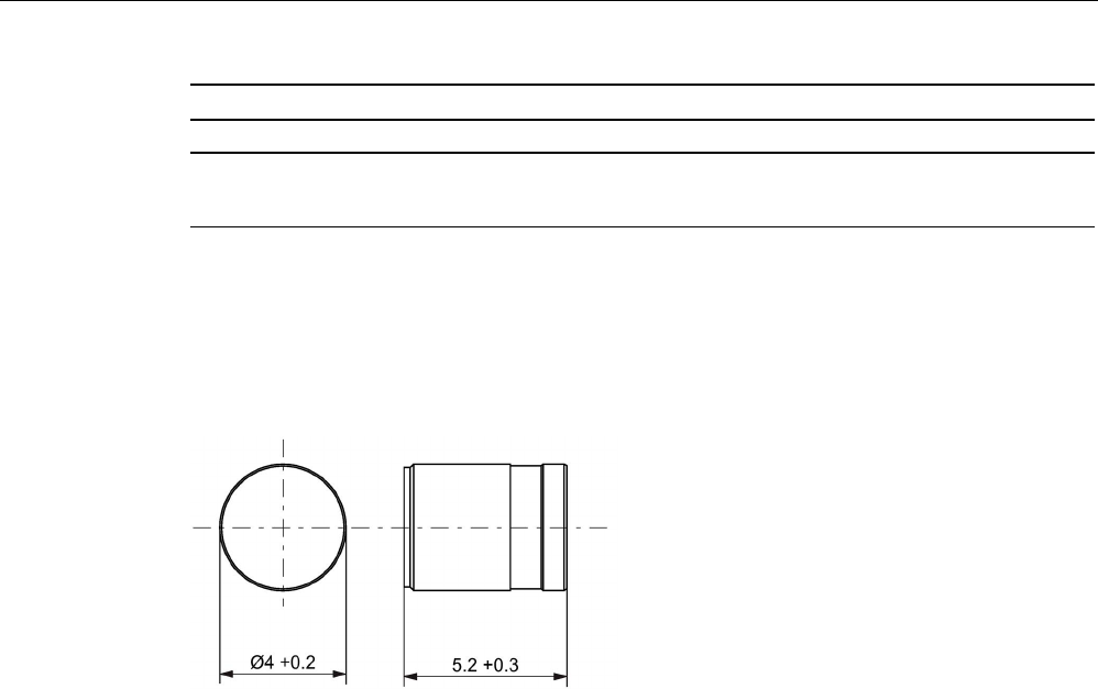
Design, dimensions and weight
Dimensions (Ø x H)
4 x 5.2 mm
Transponder
7.4 MDS D124
SIMATIC RF200
System Manual, 07/2017, J31069-D0227-U001-A9-7619 217
6GT2600-0AG00
Weight
1 g
Type of mounting • Fixing pocket
• Glued 2)
1)
The values for shock and vibration are maximum values and must not be applied continuously.
2) The processing instructions of the adhesive manufacturer must be observed.
7.3.5
Dimension drawing
Figure 7-5 Dimensions in mm
Transponder
7.4 MDS D124
SIMATIC RF200
218 System Manual, 07/2017, J31069-D0227-U001-A9-7619
7.4
MDS D124
7.4.1
Characteristics
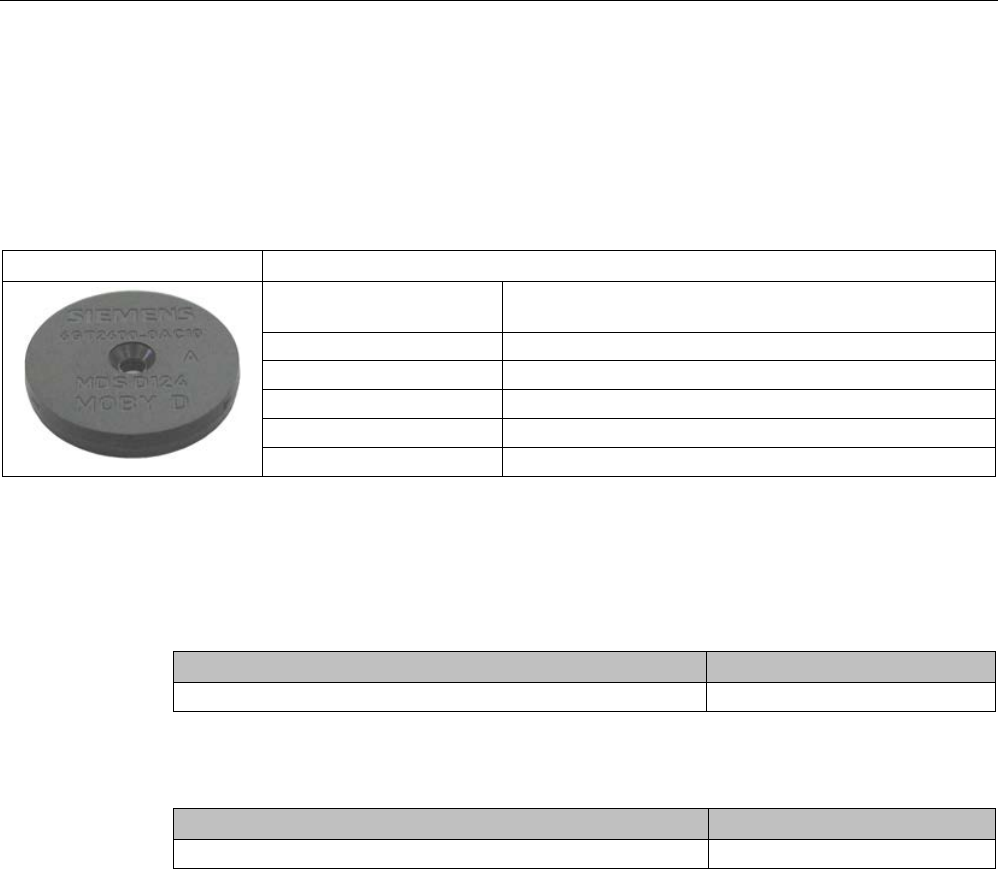
MDS D124
Characteristics
Area of application Application areas in production automation (e.g. small
paintshops up to +180 °C)
Memory size
112 bytes of EEPROM user memory
Write/read range
See section "Field data (Page 39)".
Mounting on metal Yes, with spacer
ISO standard
ISO 15693
Degree of protection
IP68/IPx9K
7.4.2
Ordering data
Table 7- 6 Ordering data for MDS D124
Article number
MDS D124
6GT2600-0AC10
Table 7- 7 Ordering data for MDS D124 accessories
Article number
Spacer
6GT2690-0AK00

Transponder
7.4 MDS D124
SIMATIC RF200
System Manual, 07/2017, J31069-D0227-U001-A9-7619 219
7.4.3
Mounting on metal
Mounting on metal
h
≥ 15 mm
Figure 7-6 Mounting the MDS D124/D324/D424/D524/E624 and RF320T on metal with spacer
Flush-mounting
h
≥ 15 mm
a
≥ 25 mm
Figure 7-7 Flush-mounting of the MDS D124/D324/D424/D524/E624 and RF320T in metal with
spacer

Transponder
7.4 MDS D124
SIMATIC RF200
220 System Manual, 07/2017, J31069-D0227-U001-A9-7619
Note
Going below the distances
If the distances (a and h) are not observed, a reduction of the field data results. It is possible
to mount the MDS with metal screws (M3 countersunk head screws). This has no tangible
impact on the range.
7.4.4
Technical specifications
Table 7- 8 Technical specifications for MDS D124
6GT2600-0AC10
Product type designation
SIMATIC MDS D124
Memory
Memory configuration
• UID • 8 bytes
• User memory • 112 bytes EEPROM
• OTP memory • 16 bytes (EEPROM)
Read cycles (at < 40 ℃)
> 10
14
Write cycles (at < 40 ℃)
> 10
6
Data retention time (at < 40 ℃)
> 10 years
Write/read distance (Sg) Dependent on the reader used, see section "Field
data (Page 39)"
MTBF (Mean Time Between Failures)
228 years
Mechanical specifications
Housing
• Material • PPS
• Color • Black
Recommended distance to metal
≥ 15 mm
Power supply
Inductive, without battery
Permitted ambient conditions
Ambient temperature
• during write/read access • -25 … +140 °C
• from +125 ℃: 20% reduction in the limit dis-
tance
• outside the read/write field • -40 to +180 ℃

Transponder
7.4 MDS D124
SIMATIC RF200
System Manual, 07/2017, J31069-D0227-U001-A9-7619 221
6GT2600-0AC10
• at +180 ℃: Tested up to 5000 hours or
3000 cycles
• during storage • -40 to +125 ℃
Degree of protection to EN 60529 • IP68
2 hours, 2 bar, +20 °C
• IPx9K
steam jet: 150 mm; 10 to 15 l/min; 100 bar; 75
°C
Shock according to EN 60721-3-7 Class 7M3
1)
1000 m/s
2
Vibration according to EN 60721-3-7 Class 7M3
1)
200 m/s
2
Torsion and bending load
Not permitted
Design, dimensions and weight
Dimensions (Ø x H)
4 x 5.2 mm
Weight
5 g
Type of mounting • 1 x M3 screw 2)
≤ 1 Nm
• Glued 3)
• With spacer
1)
The values for shock and vibration are maximum values and must not be applied continuously.
2
) To prevent it loosening during operation, secure the screw with screw locking varnish.
3) The processing instructions of the adhesive manufacturer must be observed.
7.4.5
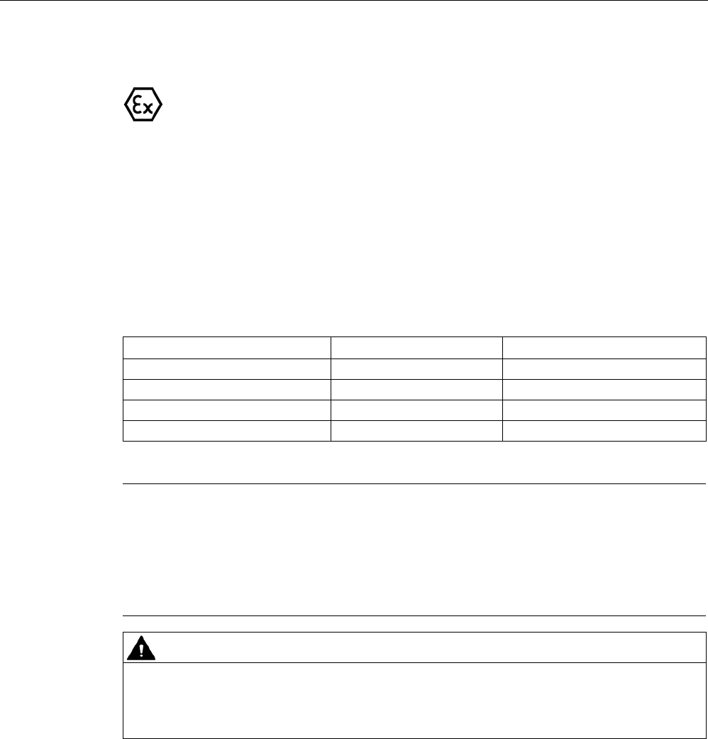
Use of the MDS D124 in hazardous area
The mobile data memory MDS D124, device group II, category 1G or 1D may be installed
and operated in zones 0, 1 and 2 or in the zones 20, 21 and 22.
The following requirements of the 94/9/EC directive are met:
● EN 60079-0:2009
● EN 60079-11:2007
● EN 61241-11:2006
● EN 60079-26:2007
When used in hazardous areas, the MDS D124 must not be operated with field strengths > 5
A / m to avoid impermissible heating. This is not the case with readers from the SIMATIC RF
range (MOBY D, RF200 and RF300).
Transponder
7.4 MDS D124
SIMATIC RF200
222 System Manual, 07/2017, J31069-D0227-U001-A9-7619
Identification
II 1 G Ex ia IIC T3 to T6 Ga
or
II 1 D Ex ia IIIC T80 °C to T180 °C Da
TÜV 12 ATEX 084413 X
The temperature class or the maximum surface temperature depends on the maximum
ambient temperature. The relationship between temperature class (gas) or maximum surface
temperature (dust) can be found in the following table.
Table 7- 9 Ambient temperature
Ambient temperature range
Temperature class
Max. surface temperature
-25 ... +150 ℃
T3
T180
-25 ... +100 ℃
T4
T130
-25 ... +65 ℃
T5
T95
-25 ... +50 ℃
T6
T80
Note
Safety markings for hazardous areas
Since there is not enough space on the MDS D124 for the safety mark, this is supplied as a
label with the device.
This must be affix
ed immediately next to the MDS D124 so that the label clearly relates to
the device.
WARNING
Gefahr durch elektrostatische Entladungen
Potential electrostatic charging hazard
Danger potentiel de charges électrostatiques
Transponder
7.4 MDS D124
SIMATIC RF200
System Manual, 07/2017, J31069-D0227-U001-A9-7619 223
Note
Installation and operating conditions for hazardous areas:
•
Use of the device in the vicinity of processes generating high charges is not allowed.
•
The device must be installed so that it is mechanically protected.
•
For applications requiring devices of category 1, the device must be mounted on a
grounded, conductive base.
•
It must only be cleaned with a damp cloth.
•
The device is suitable for use in atmospheres containing dust, however not for full
immersion in dust.
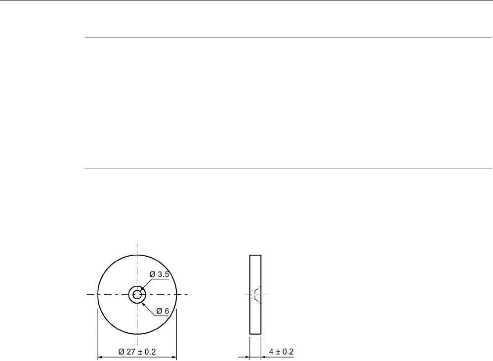
7.4.6
Dimension drawing
Figure 7-8 Dimension drawing of MDS D124
All dimensions in mm
Transponder
7.5 MDS D126
SIMATIC RF200
224 System Manual, 07/2017, J31069-D0227-U001-A9-7619
7.5
MDS D126
7.5.1
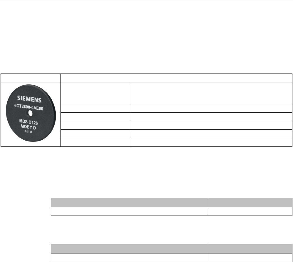
Characteristics
MDS D126
Characteristics
Area of application Compact and rugged ISO transponder; suitable for identification of
transport units in production-related logistics; can also be deployed
in harsh conditions
Memory size 112 bytes of EEPROM user memory
Write/read range
See section Field data (Page 39)
Mounting on metal
Yes, with spacer
ISO standard
ISO-15693
Degree of protection
IP68
7.5.2
Ordering data
Table 7- 10 Ordering data for MDS D126
Article number
MDS D126
6GT2600-0AE00
Table 7- 11 Ordering data for MDS D126 accessories
Article number
Spacer
6GT2690-0AL00

Transponder
7.5 MDS D126
SIMATIC RF200
System Manual, 07/2017, J31069-D0227-U001-A9-7619 225
7.5.3
Mounting on metal
Mounting on metal
h
≥ 25 mm
Figure 7-9 Mounting the MDS D126 / D426 / D526 on metal with spacer
Flush-mounted in metal
h
≥ 25 mm
a
≥ 50 mm
Figure 7-10 Flush installation of the MDS D126 / D426 / D526 in metal with spacer

Transponder
7.5 MDS D126
SIMATIC RF200
226 System Manual, 07/2017, J31069-D0227-U001-A9-7619
7.5.4
Technical specifications
Table 7- 12 Technical specifications for the MDS D126
6GT2600-0AE00
Product type designation
SIMATIC MDS D126
Memory
Memory configuration
• UID • 8 bytes
• User memory • 112 bytes EEPROM
• OTP memory • 16 bytes (EEPROM)
Read cycles (at < 40 ℃)
> 10
14
Write cycles (at < 40 ℃)
> 10
6
Data retention time (at < 40 ℃)
> 10 years
Write/read distance (Sg) Dependent on the reader used, see section "Field
data (Page 39)"
MTBF (Mean Time Between Failures)
228 years
Mechanical specifications
Housing
• Material • PA6.6 GF
• Color • Black
Recommended distance to metal
≥ 25 mm
Power supply
Inductive, without battery
Permitted ambient conditions
Ambient temperature
• during write/read access • -25 to +85 ℃
• outside the read/write field • -40 to +100 ℃
• during storage • -40 to +100 ℃
Degree of protection to EN 60529 IP68
2 hours, 2 bar, +20 °C
Shock according to EN 60721-3-7 Class 7M3
1)
500 m/s
2
Vibration according to EN 60721-3-7 Class 7M3
1)
200 m/s
2
Torsion and bending load
Not permitted
Design, dimensions and weight
Dimensions (Ø x H)
50 x 3.6 mm
Transponder
7.5 MDS D126
SIMATIC RF200
System Manual, 07/2017, J31069-D0227-U001-A9-7619 227
6GT2600-0AE00
Weight
13 g
Type of mounting • 1 x M4 screw 2)
≤ 1 Nm
• Glued 3)
1)
The values for shock and vibration are maximum values and must not be applied continuously.
2
) To prevent it loosening during operation, secure the screw with screw locking varnish.
3) The processing instructions of the adhesive manufacturer must be observed.
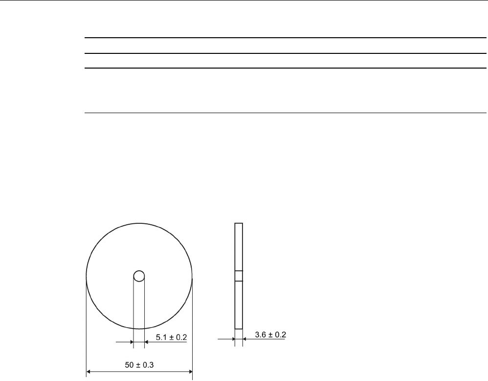
7.5.5
Dimension drawing
Dimensions in mm
Figure 7-11 Dimension drawing of MDS D126
Transponder
7.6 MDS D127
SIMATIC RF200
228 System Manual, 07/2017, J31069-D0227-U001-A9-7619
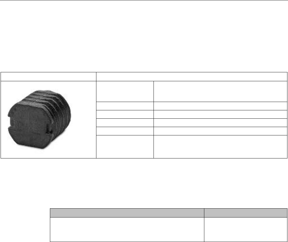
7.6
MDS D127
7.6.1
Features
MDS D127
Characteristics
Area of application Very compact data carrier that can be screwed into
areas where precise positioning is necessary;
e.g. tool identification, workpiece holders etc.
Memory size 112 bytes of EEPROM user memory
Write/read range
See section "Field data (Page 39)"
Mounting on metal
Yes, flush-mounted in metal
ISO standard
ISO 15693
Degree of protection IP68/IPx9K
7.6.2
Ordering data
Table 7- 13 Ordering data for MDS D127
Article number
MDS D127
Pack of 10
(A screw-in aid is supplied with each pack)
6GT2600-0AF00
Transponder
7.6 MDS D127
SIMATIC RF200
System Manual, 07/2017, J31069-D0227-U001-A9-7619 229
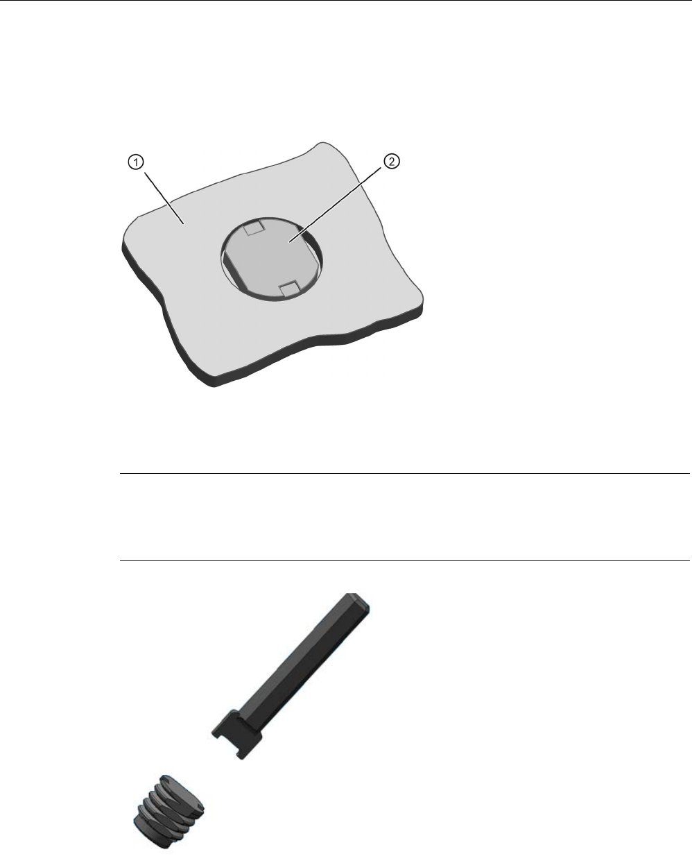
7.6.3
Mounting in metal
Flush-mounted in metal
①
Metal
②
Transponders
Note
Damage to the transponder due to improper mounting
To screw the MDS D127 into a suitable thread, use the supplied screw
-in tool. This avoids
damage to the MDS D127.
Figure 7-12 Screw-in aid for mounting the MDS D127

Transponder
7.6 MDS D127
SIMATIC RF200
230 System Manual, 07/2017, J31069-D0227-U001-A9-7619
7.6.4
Technical specifications
Table 7- 14 Technical specifications for MDS D127
6GT2600-0AF00
Product type designation
SIMATIC MDS D127
Memory
Memory configuration
• UID • 8 bytes
• User memory • 112 bytes EEPROM
• OTP memory • 16 bytes (EEPROM)
Read cycles (at < 40 ℃)
> 10
14
Write cycles (at < 40 ℃)
> 10
6
Data retention time (at < 40 ℃)
> 10 years
Write/read distance (Sg) Dependent on the reader used, see section "Field
data (Page 39)"
MTBF (Mean Time Between Failures)
228 years
Mechanical specifications
Housing
• Material • PA6
• Color • Black
Recommended distance to metal
≥ 0 mm
Power supply
Inductive, without battery
Permitted ambient conditions
Ambient temperature
• during write/read access • -25 to +100 ℃
• outside the read/write field • -40 to +125 ℃
• during storage • -40 to +125 ℃
Degree of protection to EN 60529 • IP68
2 hours, 2 bar, +20 °C
• IPx9K
steam jet: 150 mm; 10 to 15 l/min; 100 bar; 75
°C
Shock according to EN 60721-3-7 Class 7M3
1)
1000 m/s
2
Vibration according to EN 60721-3-7 Class 7M3
1)
200 m/s
2
Torsion and bending load
Not permitted
Transponder
7.6 MDS D127
SIMATIC RF200
System Manual, 07/2017, J31069-D0227-U001-A9-7619 231
6GT2600-0AF00
Design, dimensions and weight
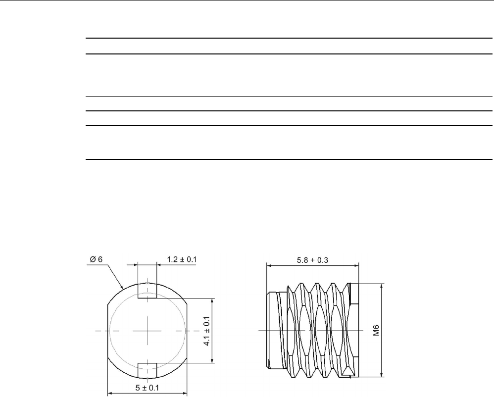
Dimensions (Ø x H)
M6 x 5.8 mm
Weight
1 g
Type of mounting • Glued 2)
• 1 x M3 screw
1)
The values for shock and vibration are maximum values and must not be applied continuously.
2) The processing instructions of the adhesive manufacturer must be observed.
7.6.5
Dimension drawing
Figure 7-13 Dimensions in mm
Transponder
7.7 MDS D139
SIMATIC RF200
232 System Manual, 07/2017, J31069-D0227-U001-A9-7619
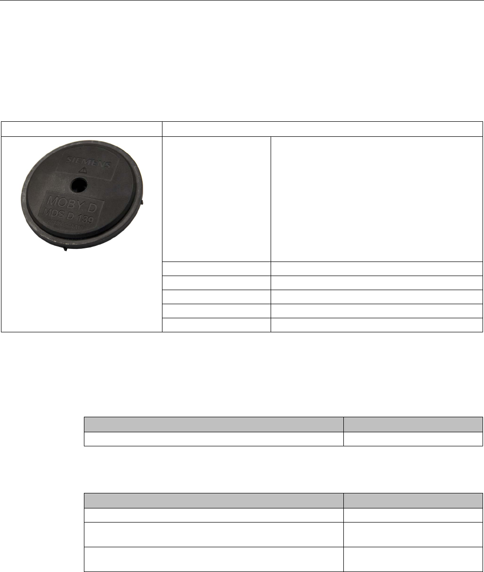
7.7
MDS D139
7.7.1
Characteristics
MDS D139
Characteristics
Area of application Applications in production logistics and in assembly
lines subject to high temperatures (up to +220 °C)
Typical application areas:
• Paintshops and their preparatory treatments)
• Primer coat, electrolytic dip area, cataphoresis
with the associated drying furnaces
• Top coat area with drying furnaces
• Washing areas at temperatures > 85 °C
• Other applications with higher temperatures
Memory size 112 bytes of EEPROM user memory
Write/read range
See section Field data (Page 39).
Mounting on metal
Yes, with spacer
ISO standard
ISO 15693
Degree of protection
IP68/IPx9K
7.7.2
Ordering data
Table 7- 15 Ordering data for MDS D139
Article number
MDS D139
6GT2600-0AA10
Table 7- 16 Ordering data for MDS D139 accessory
Article number
Spacer
6GT2690-0AA00
Quick change holder
(Ø x H): 22 x 60 mm
6GT2690-0AH00
Quick change holder
(Ø x H): 22 x 47 mm
6GT2690-0AH10
Transponder
7.7 MDS D139
SIMATIC RF200
System Manual, 07/2017, J31069-D0227-U001-A9-7619 233
7.7.3
Metal-free area
Direct mounting of the MDS D139 on metal is not allowed. A distance of ≥ 30 mm is
recommended. This can be achieved using spacers (see "Transponder holders
(Page 355)").
Mounting on metal
h
≥ 30 mm
Figure 7-14 Mounting the MDS D139 on metal with spacer
Flush-mounting
It is possible to mount the MDS D139 in metal. With large antennas, for example ANT D5,
this leads to a reduction of ranges.
h
≥ 30 mm
a
≥ 100 mm
Figure 7-15 Flush-mounting of the MDS D139 in metal with spacer

Transponder
7.7 MDS D139
SIMATIC RF200
234 System Manual, 07/2017, J31069-D0227-U001-A9-7619
Note
Going below the distances
If the distances (a and h) are not observed, a reduction of the field data results. It is possible
to mount the MDS with
metal screws (M5). This has no tangible impact on the range. It is
recommended that a test is performed in critical applications.
7.7.4
Mounting in metal
It is possible to mount the MDS D139 in metal. With large antennas, for example ANT D5,
this leads to a reduction of ranges.
a
= 100 mm
h
= 30 mm
Figure 7-16 MDS D139: Mounting in metal
7.7.5
Cleaning the transponder
NOTICE
Cleaning the transponder
Do not clean the transponder with mechanical tools, sand-blasting or pressure hose. These
cleaning methods result in damage to the transponder.
Clean the transponder only with the chemical cleansing agents listed in the section
Chemical resistance of the reader and transponders (Page 89).

Transponder
7.7 MDS D139
SIMATIC RF200
System Manual, 07/2017, J31069-D0227-U001-A9-7619 235
7.7.6
Technical specifications
Table 7- 17 Technical specifications for MDS D139
6GT2600-0AA10
Product type designation
SIMATIC MDS D139
Memory
Memory configuration
• UID • 8 bytes
• User memory • 112 bytes EEPROM
• OTP memory • 16 bytes (EEPROM)
Read cycles (at < 40 ℃)
> 10
14
Write cycles (at < 40 ℃)
> 10
6
Data retention time (at < 40 ℃)
> 10 years
Write/read distance (Sg) Dependent on the reader used, see section "Field
data (Page 39)"
MTBF (Mean Time Between Failures)
228 years
Mechanical specifications
Housing
• Material • PPS
• Color • Black
Recommended distance to metal
≥ 30 mm
Power supply
Inductive, without battery
Permitted ambient conditions
Ambient temperature
• during write/read access • -25 … +140 °C
• from +125 ℃: 20% reduction in the limit dis-
tance
• outside the read/write field • -40 to +220 ℃
• at +200 ℃: Tested up to 5000 hours or
6000 cycles
• at +220 ℃: Tested up to 2000 hours or
2000 cycles
• during storage • -40 to +100 ℃

Transponder
7.7 MDS D139
SIMATIC RF200
236 System Manual, 07/2017, J31069-D0227-U001-A9-7619
6GT2600-0AA10
Degree of protection to EN 60529 • IP68
2 hours, 2 bar, +20 °C
• IPx9K
steam jet: 150 mm; 10 to 15 l/min; 100 bar; 75
°C
Shock according to EN 60721-3-7 Class 7M3
1)
500 m/s
2
Vibration according to EN 60721-3-7 Class 7M3
1)
200 m/s
2
Torsion and bending load
Not permitted
Design, dimensions and weight
Dimensions (Ø x H)
85 x 15 mm
Weight
50 g
Type of mounting 1 x M5 screw 2)
1.5 Nm
1
The values for shock and vibration are maximum values and must not be applied continuously.
2)
For mounting with the spacer (6GT2690-0AA00), use a stainless steel M5 screw to avoid damag-
ing the MDS in high temperatures (expansion coefficient).
7.7.7
Use of the MDS D139 in hazardous areas
The MDS D139 mobile data memory is classed as a piece of simple, electrical equipment
and can be operated in Protection Zone 2, Device Group II, Category 3G.
The following requirements of the 94/9/EC directive are met:
● EN 60079-0:2006
● EN 60079-15:2005
● EN 61241-0:2006
● EN 61241-1:2004
Transponder
7.7 MDS D139
SIMATIC RF200
System Manual, 07/2017, J31069-D0227-U001-A9-7619 237
Identification
II 3 G Ex nA II T2
II 3 D Ex tD A22 IP68 T 220°C
KEMA 09 ATEX 0133 X
Ta: -25 ... +220°C
WARNING
Gefahr durch elektrostatische Entladungen
Potential electrostatic charging hazard
Danger potentiel de charges électrostatiques
Note
Installations- und Betriebsbedingungen für den Ex-Schutzbereich:
a) Der Einsatz des Gerätes in der Nähe von stark ladungserzeugenden Prozessen ist
untersagt.
b) Das Gerät ist mechanisch geschützt zu montieren.
c) Die Mo
ntage muss auf einem geerdeten, leitenden Untergrund erfolgen.
d) Die Reinigung darf nur mit feuchtem Tuch erfolgen.
Installation and operating conditions for hazardous areas:
a) Use of the equipment in the vicinity of processes generating high charges is
not allowed.
b) The equipment must be mechanically protected when installed.
c) Installation must be performed on a grounded and conductive mounting surface.
d) Cleaning only with a wet cloth
Conditions d'installation et de mise en oeuvre pour la zone de protection Ex :
a) L'utilisation de l'appareil près de processus générant de fortes charges est interdite.
b) L'appareil doit être monté de manière à être protégé mécaniquement.
c) Le montage doit être effectué sur un socle conducteur mis à la terre.
d) N
ettoyage uniquement avec un chiffon humide
Transponder
7.7 MDS D139
SIMATIC RF200
238 System Manual, 07/2017, J31069-D0227-U001-A9-7619
7.7.8
Dimension drawings
Dimensional drawing of MDS D139
Figure 7-17 Dimensional drawing of MDS D139
Dimensions in mm
Transponder
7.8 MDS D160
SIMATIC RF200
System Manual, 07/2017, J31069-D0227-U001-A9-7619 239
7.8
MDS D160
7.8.1
Characteristics
MDS D160
Characteristics
Area of application Thanks to its rugged packaging, the MDS D160 is a transponder that
can be used under extreme environmental conditions. It is washable,
heat-resistant and resistant to all chemicals generally used in the
laundry process.
Typical applications are, for example:
• Rented work clothing
• Hotel laundry
• Surgical textiles
• Hospital clothing
• Dirt collection mats
• Clothing for nursing homes/hostels
Memory size 112 bytes of EEPROM user memory
Write/read range
See section Field data (Page 39).
Mounting on metal
Yes, with spacer
ISO standard
ISO 15693
Degree of protection
IP68/IPx9K
7.8.2
Ordering data
Table 7- 18 Ordering data for MDS D160
Article number
MDS D160
6GT2600-0AB10
Table 7- 19 Ordering data for MDS D160 accessories
Article number
Spacer
6GT2690-0AG00
Transponder
7.8 MDS D160
SIMATIC RF200
240 System Manual, 07/2017, J31069-D0227-U001-A9-7619
7.8.3
Mounting on metal
Mounting on metal
①
Transponder
②
Metal carrier
③
Spacer
h
≥ 10 mm
Figure 7-18 Mounting the MDS D160 on metal with spacer
Note
Going below the minimum distance (h)
If the minimum distance (h) is not observed, a reduction of the fie
ld data results.
In critical applications, it is recommended that a test is performed.
Flush-mounting
Flush-mounting of the MDS D160 in metal is not permitted!
7.8.4
Technical specifications
Table 7- 20 Technical specifications for the MDS D160
6GT2600-0AB10
Product type designation
SIMATIC MDS D160
Memory
Memory configuration
• UID • 8 bytes
• User memory • 112 bytes EEPROM

Transponder
7.8 MDS D160
SIMATIC RF200
System Manual, 07/2017, J31069-D0227-U001-A9-7619 241
6GT2600-0AB10
• OTP memory • 16 bytes (EEPROM)
Read cycles (at < 40 ℃)
> 10
14
Write cycles (at < 40 ℃)
> 10
6
Data retention time (at < 40 ℃)
> 10 years
Write/read distance (Sg) Dependent on the reader used, see section "Field
data (Page 39)"
MTBF (Mean Time Between Failures)
228 years
Mechanical specifications
Housing
• Material
• Color
• PPS
• beige
Recommended distance to metal
≥ 10 mm
Power supply
Inductive, without battery
Permitted ambient conditions
Ambient temperature
• during write/read access
• -25 … +85 °C
• outside the read/write field • -40 … +175 °C
• from +125 ℃: for 1000 hours, 20% reduction
of the limit distance
• at +175 ℃: 100 washing cycles tested
• at +220 ℃: Tested once for up to 30 seconds
• during storage • -25 to +100 ℃
Mechanical strength
• Isostatic pressure • 300 bar for 5 min
• Axial pressure • 1000 N for 10 s
• Radial pressure • 1000 N for 10 s
Resistance to chemicals All chemicals normally used in the washing pro-
cess
MDS lifespan
At least 100 wash cycles
Degree of protection • IP68
24 hours, 2 bar, +20 °C
• IPx9K
Shock according to IEC 68-2-271) 400 m/s2
18 ms; 6 axes; 2000 repetitions/h
Vibration according to IEC 68-2-61) 100 m/s2
10 ... 2000 Hz; 3 axes; 2.5 h
Transponder
7.8 MDS D160
SIMATIC RF200
242 System Manual, 07/2017, J31069-D0227-U001-A9-7619
6GT2600-0AB10
Torsion and bending load
Not permitted
Design, dimensions and weight
Dimensions (Ø x H)
16 x 3 mm
Weight
1.2 g
Type of mounting • Patched
• Sewn in
• Glued 2)
1)
The values for shock and vibration are maximum values and must not be applied continuously.
2) The processing instructions of the adhesive manufacturer must be observed.
Note
Regeneration time between washing cycles
The regeneration time for the MDS D160 between washing cycles must be at least 24 hours.
7.8.5
Dimension drawings
Dimensional drawing of MDS D160
Dimensions in mm
Figure 7-19 Dimensional drawing of MDS D160
Transponder
7.9 MDS D165
SIMATIC RF200
System Manual, 07/2017, J31069-D0227-U001-A9-7619 243
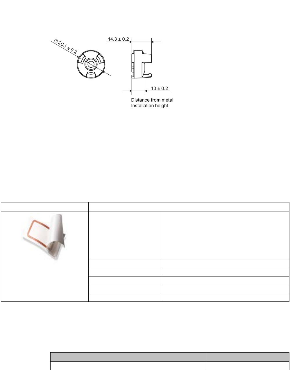
Dimensional drawing of spacer
Dimensions in mm
Figure 7-20 Dimensional drawing of spacer
7.9
MDS D165
7.9.1
Features
MDS D165 (special version)
Characteristics
Area of application The design of the transponder (self-adhesive label)
permits a variety of designs, guaranteeing optimum
dimensioning for the widest variety of applications.
From simple identification such as electronic barcode
replacement/supplementation, through warehouse
and distribution logistics, right up to product identifi-
cation.
Memory size
112 bytes of EEPROM user memory
Write/read range
See section Field data (Page 39).
Mounting on metal Yes, with spacer
ISO standard
ISO 15693
Degree of protection
IP65
7.9.2
Ordering data
Table 7- 21 Ordering data for MDS D165
Article number
MDS D165 (special version ISO-CARD)
6GT2600-1AB00-0AX0

Transponder
7.9 MDS D165
SIMATIC RF200
244 System Manual, 07/2017, J31069-D0227-U001-A9-7619
Type of delivery
Minimum order quantity: 1250 units (5 rolls with 250 units each)
7.9.3
Technical data
Table 7- 22 Technical specifications for MDS D165
6GT2600-1AB00-0AX0
Product type designation
SIMATIC MDS D165
Memory
Memory configuration
• UID • 8 bytes
• User memory • 112 bytes EEPROM
• OTP memory • 16 bytes (EEPROM)
Read cycles (at < 40 ℃)
> 10
14
Write cycles (at < 40 ℃)
> 10
6
Data retention time (at < 40 ℃)
> 10 years
Write/read distance (Sg) Dependent on the reader used, see section "Field
data (Page 39)"
MTBF (Mean Time Between Failures)
228 years
Mechanical specifications
Housing
• Material • Top • PET plastic (label
material)
• Inlay • PET plastic (carrier
material)
• Antenna • Aluminum
• Bottom • Double-sided trans-
fer adhesive on sili-
con paper
• Color • White
Recommended distance to metal
≥ 25 mm
Power supply
Inductive, without battery
Permitted ambient conditions
Ambient temperature
• during write/read access • -25 ... +80 °C
Transponder
7.9 MDS D165
SIMATIC RF200
System Manual, 07/2017, J31069-D0227-U001-A9-7619 245
6GT2600-1AB00-0AX0
• outside the read/write field • -25 to +80 ℃
• during storage • +20 to +30 ℃
Can be stored for 2 years, determined by the
durability of the adhesive.
Degree of protection
IP65
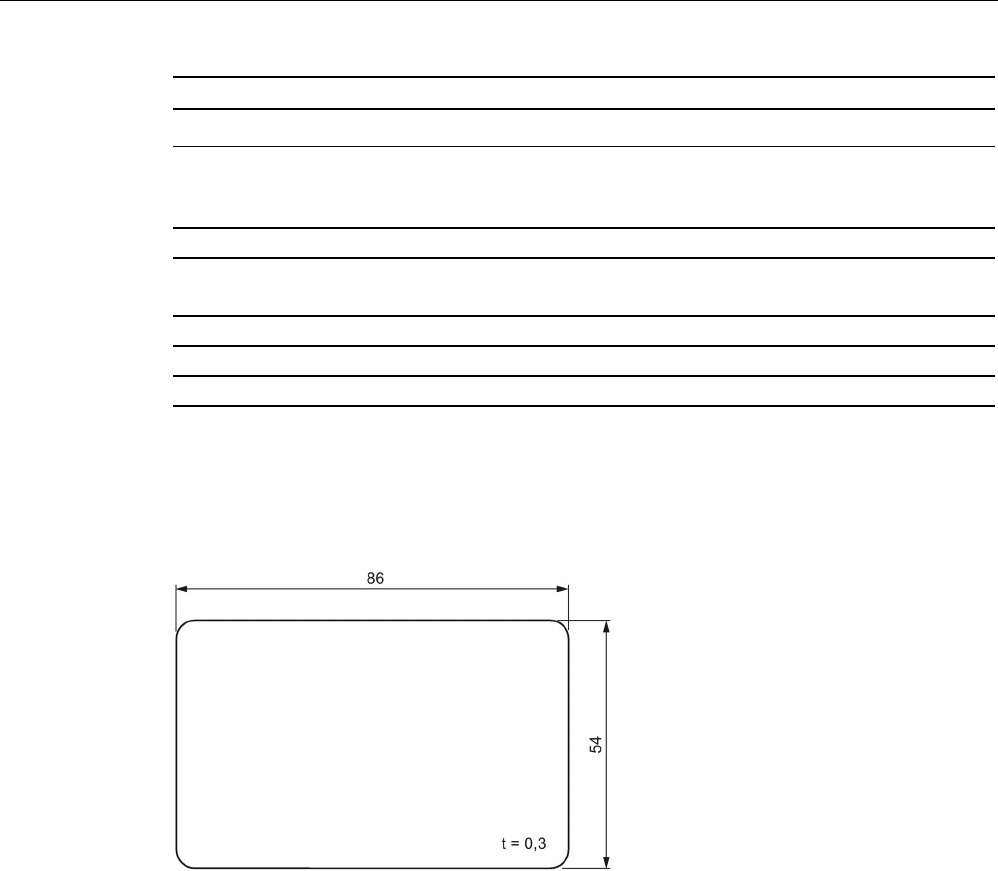
Design, dimensions and weight
Dimensions (L x W x H)
86 x 54 x 0.3 mm
Weight
1 g
Type of mounting
Glued with self-adhesive label
1)
1) The processing instructions of the adhesive manufacturer must be observed.
7.9.4
Dimension drawing
Dimensions in mm
Figure 7-21 Dimension drawing of MDS D165
Transponder
7.10 MDS D200
SIMATIC RF200
246 System Manual, 07/2017, J31069-D0227-U001-A9-7619
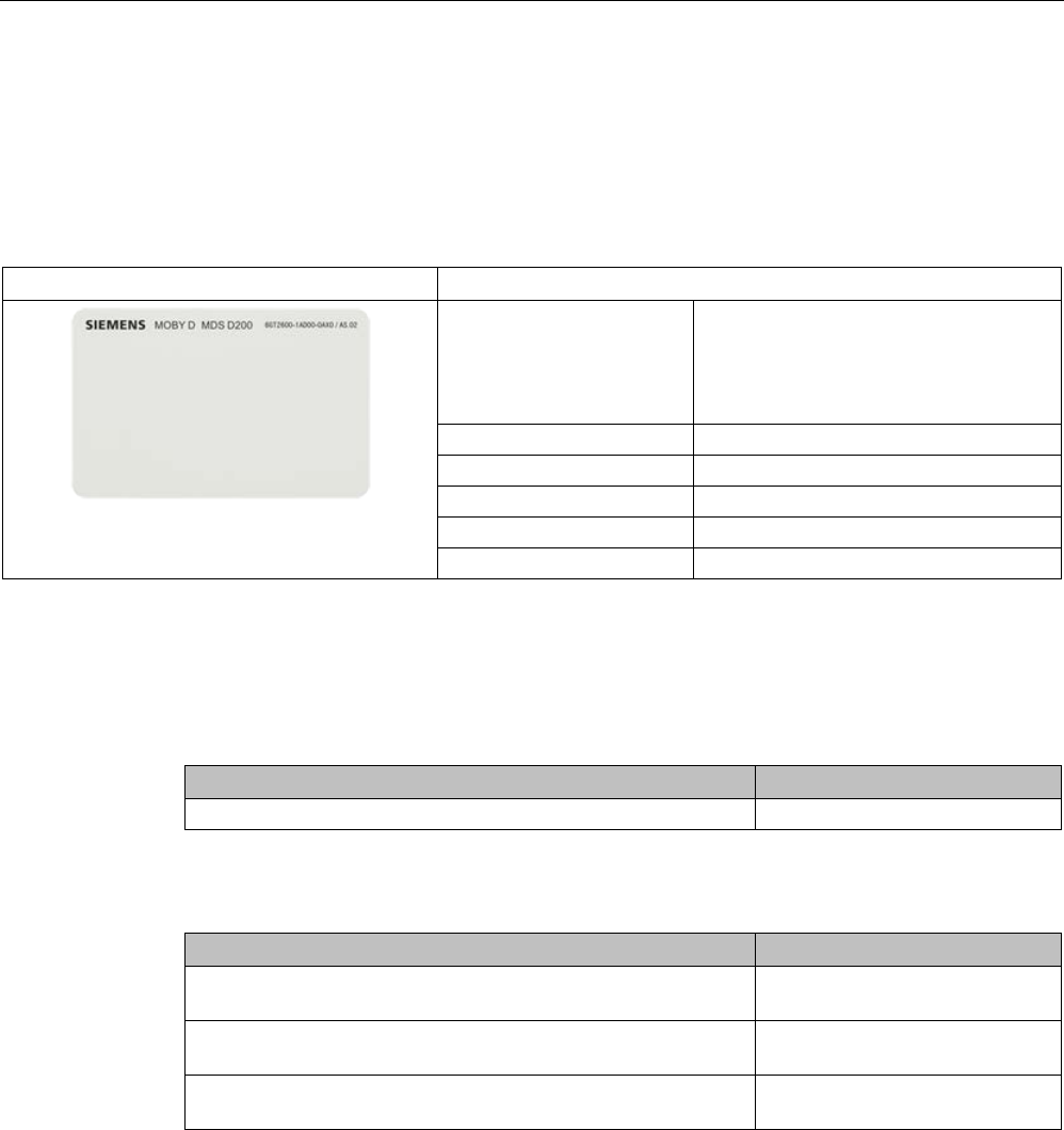
7.10
MDS D200
7.10.1
Features
MDS D200
Characteristics
Area of application From simple identification such as elec-
tronic barcode replace-
ment/supplementation, through
warehouse and distribution logistics, right
up to product identification.
Memory size
256 bytes of EEPROM user memory
Write/read range
See section Field data (Page 39).
Mounting on metal
Yes, with spacer
ISO standard
15693 with Tag-it HFI technology
Degree of protection
IP67
7.10.2
Ordering data
Table 7- 23 Ordering data for MDS D200
Article number
MDS D200 (special version ISO-CARD)
6GT2600-1AD00-0AX0
Table 7- 24 Ordering data for MDS D200 accessories
Article number
Spacer
(in conjunction with fixing pocket 6GT2190-0AB00)
6GT2190-0AA00
Fixing pocket
(in conjunction with spacer 6GT2190-0AA00)
6GT2190-0AB00
Fixing pocket
(not suitable for fixing directly onto metal)
6GT2390-0AA00
Transponder
7.10 MDS D200
SIMATIC RF200
System Manual, 07/2017, J31069-D0227-U001-A9-7619 247
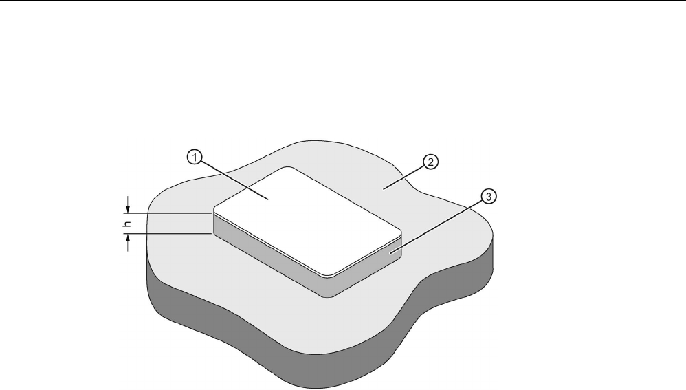
7.10.3
Mounting on metal
Mounting on metal
h
≥ 20 mm
①
Transponder
②
Metal
③
Non-metal
Figure 7-22 Mounting of the MDS D200 on metal with spacer

Transponder
7.10 MDS D200
SIMATIC RF200
248 System Manual, 07/2017, J31069-D0227-U001-A9-7619
Flush-mounting
a
≥ 20 mm
h
≥ 20 mm
①
Transponder
②
Metal
③
Non-metal
Figure 7-23 Flush-mounting of MDS D200 in metal with spacer
Note
If the minimum guide values (h) are not observed, a reductio
n of the field data results.
7.10.4
Technical data
Table 7- 25 Technical specifications for MDS D200
6GT2600-1AD00-0AX0
Product type designation
SIMATIC MDS D200
Memory
Memory configuration
• UID • 8 bytes
• User memory • 256 bytes EEPROM

Transponder
7.10 MDS D200
SIMATIC RF200
System Manual, 07/2017, J31069-D0227-U001-A9-7619 249
6GT2600-1AD00-0AX0
• OTP memory • 16 bytes (EEPROM)
Read cycles (at < 25 ℃)
> 10
14
Write cycles (at < 25 ℃)
> 10
6
Data retention time (at < 25 ℃)
> 10 years
Write/read distance (Sg) Dependent on the reader used, see section "Field
data (Page 39)"
MTBF (Mean Time Between Failures)
228 years
Mechanical specifications
Housing
• Material • PET
• Color • White
Recommended distance to metal
≥ 20 mm
Power supply
Inductive, without battery
Permitted ambient conditions
Ambient temperature
• during write/read access • -20 to +60 ℃
• outside the read/write field • -20 to +60 ℃
• during storage • -20 to +60 ℃
Degree of protection to EN 60529
IP67
Shock-resistant to EN 60721-3-7 class 7M3
ISO 10373 / ISO 7810
1)
Vibration-resistant to EN 60721-3-7, class 7M3
ISO 10373 / ISO 7810
1)
Torsion and bending load
ISO 10373/ISO 7816-1
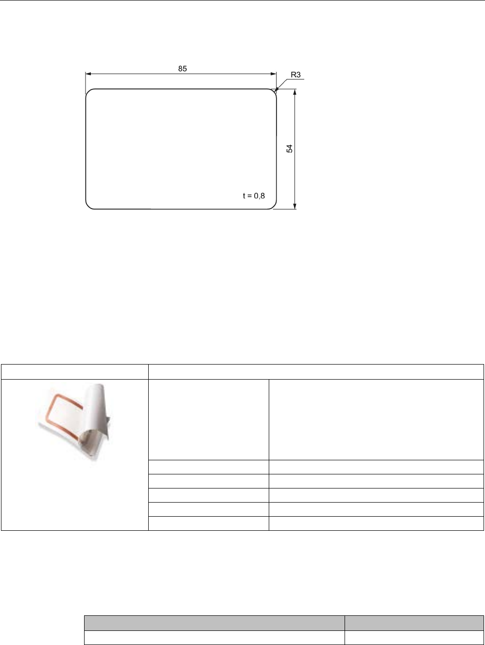
Design, dimensions and weight
Dimensions (L x W x H)
85 x 54 x 0.8 mm
Weight
5 g
Type of mounting • Fixing pocket
• Glued 2)
1)
The values for shock and vibration are maximum values and must not be applied continuously.
2) The processing instructions of the adhesive manufacturer must be observed.
Transponder
7.11 MDS D261
SIMATIC RF200
250 System Manual, 07/2017, J31069-D0227-U001-A9-7619
7.10.5
Dimension drawing
Dimensions in mm
Figure 7-24 Dimension drawing of MDS D200
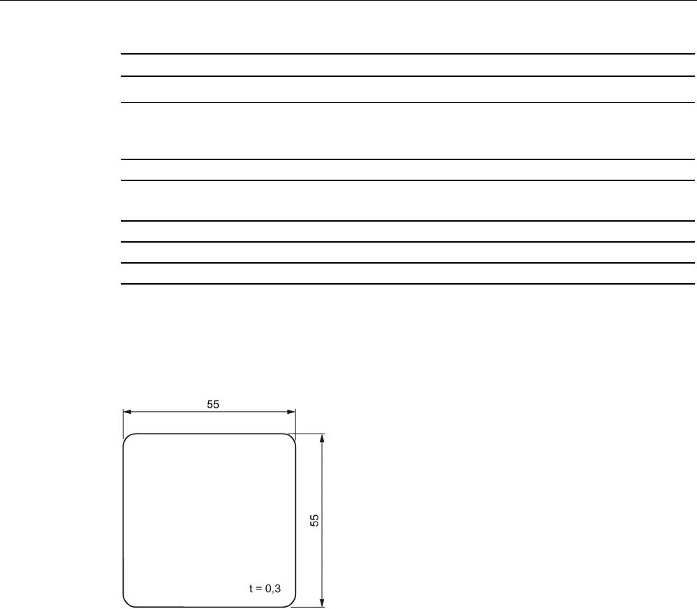
7.11
MDS D261
7.11.1
Features
MDS D261
Characteristics
Area of application The design of the transponder (self-adhesive label)
permits a variety of designs, guaranteeing optimum
dimensioning for the widest variety of applications.
From simple identification such as electronic barcode
replacement/supplementation, through warehouse
and distribution logistics, right up to product identifi-
cation.
Memory size
256 bytes of EEPROM user memory
Write/read range
See section Field data (Page 39).
Mounting on metal
Yes, with spacer
ISO standard
ISO 15693
Degree of protection
IP65
7.11.2
Ordering data
Table 7- 26 Ordering data for MDS D261
Article number
MDS D261
6GT2600-1AA00-0AX0

Transponder
7.11 MDS D261
SIMATIC RF200
System Manual, 07/2017, J31069-D0227-U001-A9-7619 251
Type of delivery
Minimum order quantity: 1250 units (5 rolls with 250 units each)
7.11.3
Technical data
Table 7- 27 Technical specifications of MDS D261
6GT2600-1AA01-0AX0
Product type designation
SIMATIC MDS D261
Memory
Memory configuration
• UID • 8 bytes
• User memory • 256 bytes EEPROM
• OTP memory • 16 bytes (EEPROM)
Read cycles (at < 40 ℃)
> 10
14
Write cycles (at < 40 ℃)
> 10
6
Data retention time (at < 40 ℃)
> 10 years
Write/read distance (Sg) Dependent on the reader used, see section "Field
data (Page 39)"
MTBF (Mean Time Between Failures)
228 years
Mechanical specifications
Housing
• Material • Top • PET plastic (label
material)
• Inlay • PET plastic (carrier
material)
• Antenna • Aluminum
• Bottom • Double-sided trans-
fer adhesive on sili-
con paper
• Color • White
Recommended distance to metal
≥ 25 mm
Power supply
Inductive, without battery
Permitted ambient conditions
Ambient temperature
• during write/read access • -20 ... +60 °C
Transponder
7.11 MDS D261
SIMATIC RF200
252 System Manual, 07/2017, J31069-D0227-U001-A9-7619
6GT2600-1AA01-0AX0
• outside the read/write field • -20 … +85 °C
• During transportation and storage • +20 to +30 ℃
Can be stored for 2 years, determined by the
durability of the adhesive
Degree of protection
IP65
Design, dimensions and weight
Dimensions (L x W x H)
55 x 55 x 0.3 mm
Weight
1 g
Type of mounting
Glued with self-adhesive label
1)
1) The processing instructions of the adhesive manufacturer must be observed.
7.11.4
Dimension drawing
Dimensions in mm
Figure 7-25 Dimension drawing of MDS D261
Transponder
7.12 MDS D324
SIMATIC RF200
System Manual, 07/2017, J31069-D0227-U001-A9-7619 253
7.12
MDS D324
7.12.1
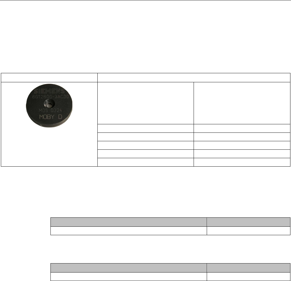
Characteristics
MDS D324
Characteristics
Area of application Production and distribution logistics
and product identification
Can also be used in harsh environ-
ments under extreme environmental
conditions (e.g. with higher temperature
load).
Memory size
992 bytes of EEPROM user memory
Write/read range
See section "Field data (Page 39)."
Mounting on metal
Yes, with spacer
ISO standard
ISO 15693
Degree of protection
IP67; IPx9K
7.12.2
Ordering data
Table 7- 28 Ordering data MDS D324
Article number
MDS D324
6GT2600-3AC00
Table 7- 29 Ordering data MDS D324 accessories
Article number
Spacer
6GT2690-0AK00
Transponder
7.12 MDS D324
SIMATIC RF200
254 System Manual, 07/2017, J31069-D0227-U001-A9-7619
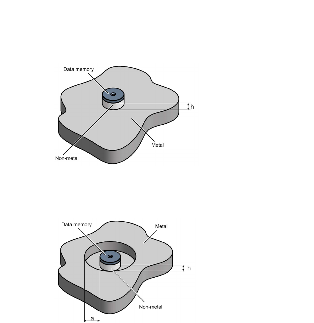
7.12.3
Mounting on metal
Mounting on metal
h
≥ 15 mm
Figure 7-26 Mounting the MDS D124/D324/D424/D524/E624 and RF320T on metal with spacer
Flush-mounting
h
≥ 15 mm
a
≥ 25 mm
Figure 7-27 Flush-mounting of the MDS D124/D324/D424/D524/E624 and RF320T in metal with
spacer

Transponder
7.12 MDS D324
SIMATIC RF200
System Manual, 07/2017, J31069-D0227-U001-A9-7619 255
Note
Going below the distances
If the distances (a and h) are not observed, a reduction of the field data results. It is possible
to mount the MDS with metal screws (M3 countersunk head screws). This has n
o tangible
impact on the range.
7.12.4
Technical specifications
Table 7- 30 Technical specifications of MDS D324
6GT2600-3AC00
Product type designation
SIMATIC MDS D324
Memory
Memory configuration
• UID • 8 bytes
• User memory • 992 bytes EEPROM
• OTP memory • 16 bytes (EEPROM)
Read cycles (at < 40 ℃)
> 10
14
Write cycles (at < 40 ℃)
> 10
6
Data retention time (at < 40 ℃)
> 10 years
Write/read distance (Sg) Dependent on the reader used, see section "Field
data (Page 39)"
MTBF (Mean Time Between Failures)
228 years
Mechanical specifications
Housing
• Material • Epoxy resin
• Color • Black
Recommended distance to metal
≥ 15 mm
Power supply
Inductive, without battery
Permitted ambient conditions
Ambient temperature
• during write/read access • -25 to +125 ℃
• outside the read/write field • -40 to +140 ℃
• during storage • -40 to +140 ℃
Transponder
7.12 MDS D324
SIMATIC RF200
256 System Manual, 07/2017, J31069-D0227-U001-A9-7619
6GT2600-3AC00
Degree of protection to EN 60529 • IP67
• IPx9K
Shock according to EN 60721-3-7 Class 7M3
1)
1000 m/s
2
Vibration according to EN 60721-3-7 Class 7M3
1)
200 m/s
2
Torsion and bending load
Not permitted
Design, dimensions and weight
Dimensions (Ø x H)
27 x 4 mm
Weight
5 g
Type of mounting • 1 x M3 screw 2)
≤ 1 Nm
• Glued 3)
1)
The values for shock and vibration are maximum values and must not be applied continuously.
2
) To prevent it loosening during operation, secure the screw with screw locking varnish.
3) The processing instructions of the adhesive manufacturer must be observed.
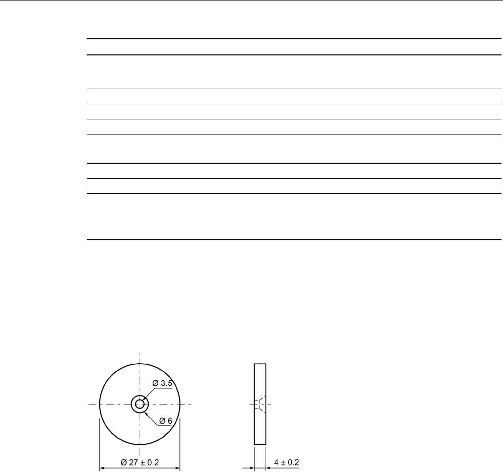
7.12.5
Dimension drawing
Figure 7-28 Dimension drawing of MDS D324
All dimensions in mm
Transponder
7.13 MDS D339
SIMATIC RF200
System Manual, 07/2017, J31069-D0227-U001-A9-7619 257
7.13
MDS D339
7.13.1
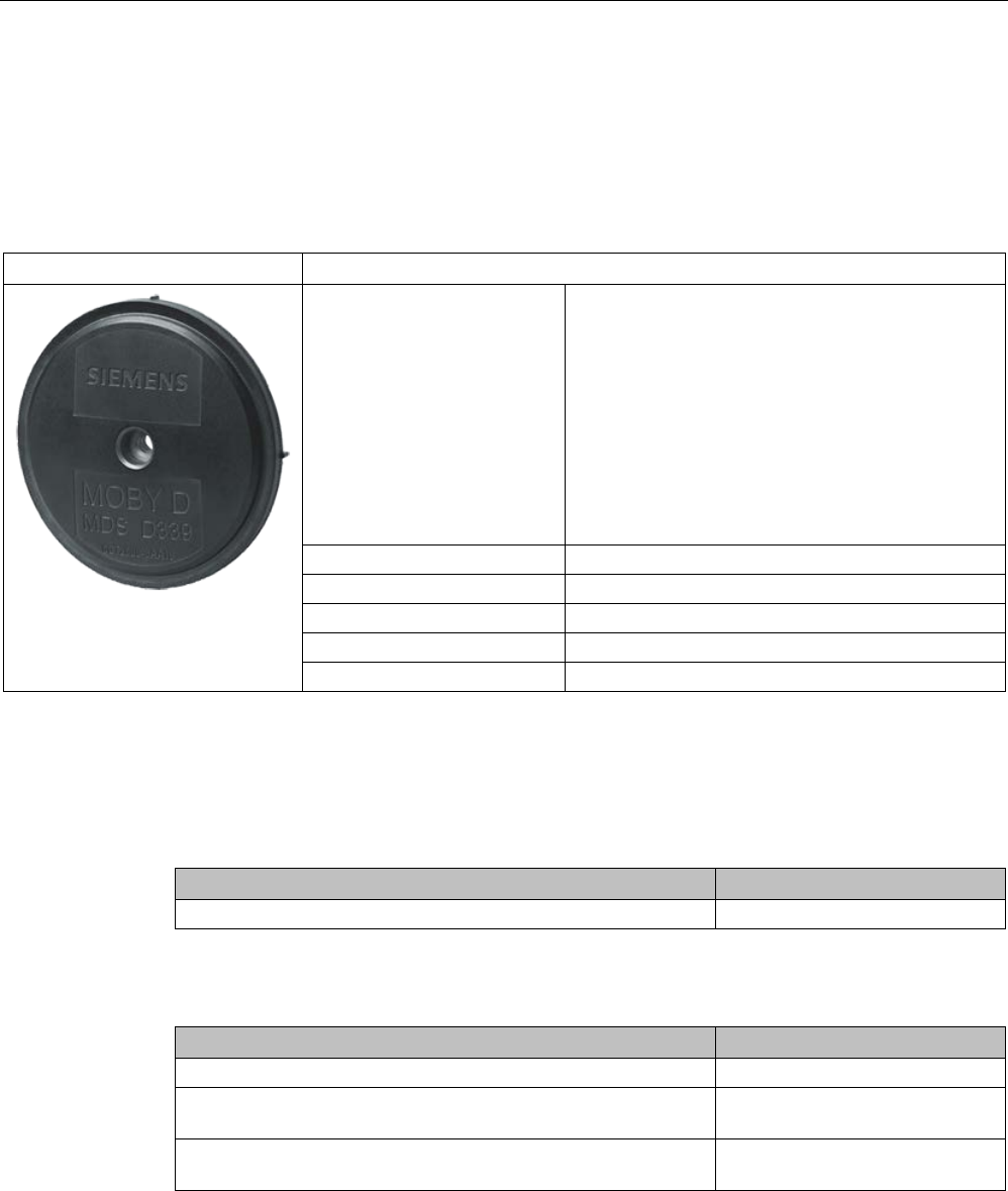
Characteristics
MDS D339
Characteristics
Area of application Applications in production automation with high
temperature demands (up to +220 °C)
Typical application areas:
• Paintshops and their preparatory treatments
• Primer coat, electrolytic dip area, cataphoresis
with the associated drying furnaces
• Top coat area with drying furnaces
• Washing areas at temperatures > 85 °C
• Other applications with higher temperatures
Memory size 992 bytes of EEPROM user memory
Write/read range
See section Field data (Page 39).
Mounting on metal
Yes, with spacer
ISO standard
ISO 15693
Degree of protection
IP68/IPx9K
7.13.2
Ordering data
Table 7- 31 Ordering data for MDS D339
Article number
MDS D339
6GT2600-3AA10
Table 7- 32 Ordering data for MDS D339 accessories
Article number
Spacer
6GT2690-0AA00
Quick change holder
(Ø x H): 22 x 60 mm
6GT2690-0AH00
Quick change holder
(Ø x H): 22 x 47 mm
6GT2690-0AH10
Transponder
7.13 MDS D339
SIMATIC RF200
258 System Manual, 07/2017, J31069-D0227-U001-A9-7619
7.13.3
Mounting on metal
Direct mounting of the MDS D139/D339 on metal is not allowed. A distance of ≥ 30 mm is
recommended. This can be achieved using spacers (see "Transponder holders
(Page 355)").
Mounting on metal
h
≥ 30 mm
Figure 7-29 Mounting the MDS D139/D339 on metal with spacer
Flush-mounting
It is possible to mount the MDS D139/D339 in metal. With large antennas, for example ANT
D5, this leads to a reduction of ranges.
h
≥ 30 mm
a
≥ 100 mm
Figure 7-30 Flush-mounting of the MDS D139/D339 in metal with spacer
Transponder
7.13 MDS D339
SIMATIC RF200
System Manual, 07/2017, J31069-D0227-U001-A9-7619 259
Note
Going below the distances
If the distances (a and h) are not observed, a reduction of the field data results. It is possi
ble
to mount the MDS with metal screws (M5). This has no tangible impact on the range. It is
recommended that a test is performed in critical applications.
7.13.4
Mounting in metal
It is possible to mount the MDS D339 in metal. With large antennas, for example ANT D5,
this leads to a reduction of ranges.
a
= 100 mm
h
= 30 mm
Figure 7-31 MDS D339: Mounting in metal
7.13.5
Cleaning the transponder
NOTICE
Cleaning the transponder
Do not clean the transponder with mechanical tools, sand-blasting or pressure hose. These
cleaning methods result in damage to the transponder.
Clean the transponder only with the chemical cleansing agents listed in the section
Chemical resistance of the reader and transponders (Page 89).

Transponder
7.13 MDS D339
SIMATIC RF200
260 System Manual, 07/2017, J31069-D0227-U001-A9-7619
7.13.6
Technical specifications
Table 7- 33 Technical specifications of MDS D339
6GT2600-3AA10
Product type designation
SIMATIC MDS D339
Memory
Memory configuration
• UID • 8 bytes
• User memory • 992 bytes EEPROM
• OTP memory • 16 bytes (EEPROM)
Read cycles (at < 40 ℃)
> 10
14
Write cycles (at < 40 ℃)
> 10
6
Data retention time (at < 40 ℃)
> 10 years
Write/read distance (Sg) Dependent on the reader used, see section "Field
data (Page 39)"
MTBF (Mean Time Between Failures)
228 years
Mechanical specifications
Housing
• Material • PPS
• Color • Black
Recommended distance to metal
≥ 30 mm
Power supply
Inductive, without battery
Permitted ambient conditions
Ambient temperature
• during write/read access • -25 to +100 ℃
• outside the read/write field • -40 to +220 ℃
• from +125 ℃: 20% reduction in the limit dis-
tance
• at +200 ℃: Tested up to 5000 hours or
6000 cycles
• at +220 ℃: Tested up to 2000 hours or
2000 cycles
• during storage • -40 to +100 ℃

Transponder
7.13 MDS D339
SIMATIC RF200
System Manual, 07/2017, J31069-D0227-U001-A9-7619 261
6GT2600-3AA10
Degree of protection to EN 60529 • IP68
2 hours, 2 bar, +20 °C
• IPx9K
steam jet: 150 mm; 10 to 15 l/min; 100 bar; 75
°C
Shock according to EN 60721-3-7 Class 7M3
1)
500 m/s
2
Vibration according to EN 60721-3-7 Class 7M3
1)
200 m/s
2
Torsion and bending load
Not permitted
Design, dimensions and weight
Dimensions (Ø x H)
85 x 15 mm
Weight
50 g
Type of mounting 1 x M5 screw 2)
1.5 Nm
1
The values for shock and vibration are maximum values and must not be applied continuously.
2)
For mounting with the spacer (6GT2690-0AA00), use a stainless steel M5 screw to avoid damag-
ing the MDS in high temperatures (expansion coefficient).
7.13.7
Use of the MDS D339 in hazardous areas
The MDS D339 mobile data memory is classed as a piece of simple, electrical equipment
and can be operated in Protection Zone 2, Device Group II, Category 3G.
The following requirements of the 94/9/EC directive are met:
● EN 60079-0:2006
● EN 60079-15:2005
● EN 61241-0:2006
● EN 61241-1:2004
Transponder
7.13 MDS D339
SIMATIC RF200
262 System Manual, 07/2017, J31069-D0227-U001-A9-7619
Identification
II 3 G Ex nA II T6
Ii 3 D Ex tD A22 IP68 T 210°C
KEMA 09 ATEX 0133 X
WARNING
Gefahr durch elektrostatische Entladungen
Potential electrostatic charging hazard
Danger potentiel de charges électrostatiques
Note
Installations- und Betriebsbedingungen für den Ex-Schutzbereich:
a
) Der Einsatz des Gerätes in der Nähe von stark ladungserzeugenden Prozessen ist
untersagt.
b) Das Gerät ist mechanisch geschützt zu montieren.
c) Die Montage muss auf einem geerdeten, leitenden Untergrund erfolgen.
d) Die Reinigung darf nur mit feuchtem T
uch erfolgen.
Installation and operating conditions for hazardous areas:
a) Use of the equipment in the vicinity of processes generating high charges is not allowed.
b) The equipment must be mechanically protected when installed.
c) Installation must be p
erformed on a grounded and conductive mounting surface.
d) Cleaning only with a wet cloth
Conditions d'installation et de mise en oeuvre pour la zone de protection Ex :
a) L'utilisation de l'appareil près de processus générant de fortes charges est interd
ite.
b) L'appareil doit être monté de manière à être protégé mécaniquement.
c) Le montage doit être effectué sur un socle conducteur mis à la terre.
d) Nettoyage uniquement avec un chiffon humide

Transponder
7.13 MDS D339
SIMATIC RF200
System Manual, 07/2017, J31069-D0227-U001-A9-7619 263
7.13.8
Dimensional drawing
MDS D339
Figure 7-32 Dimension drawing of the MDS D339
Dimensions in mm
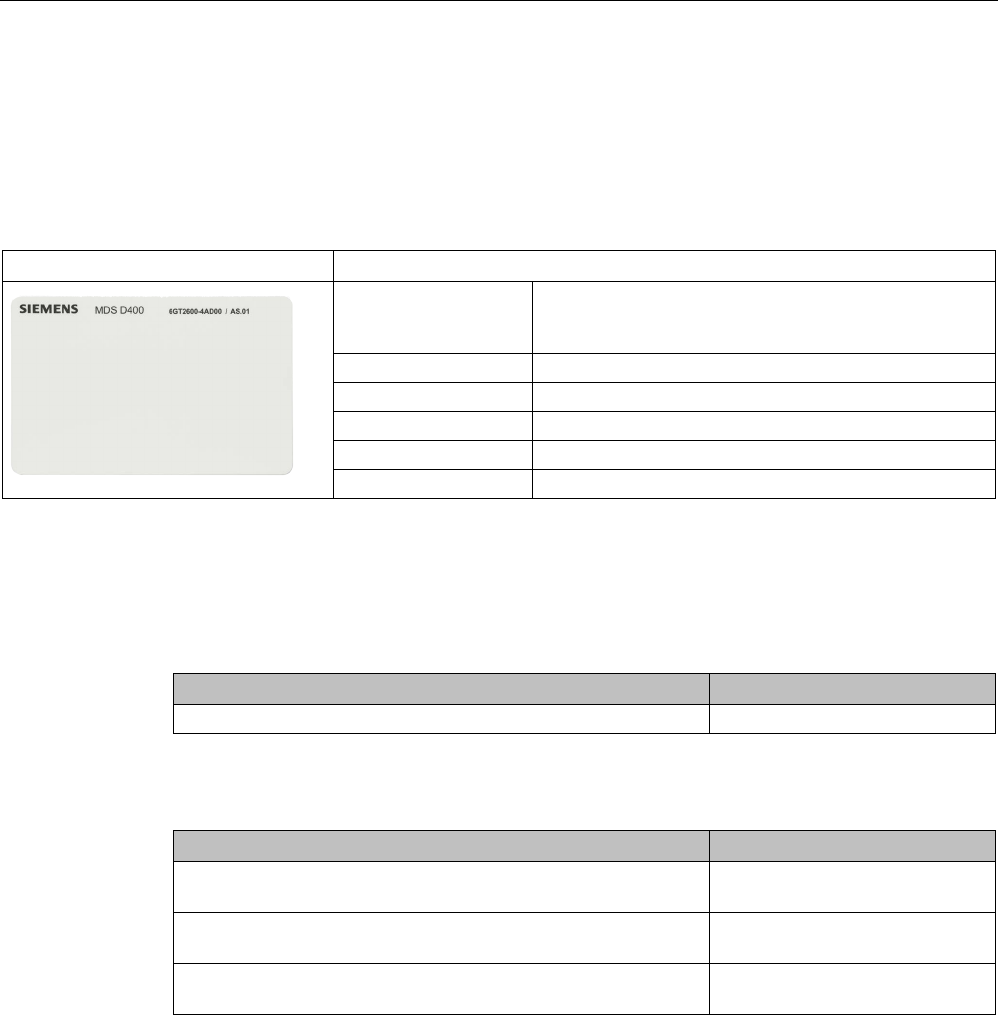
Transponder
7.14 MDS D400
SIMATIC RF200
264 System Manual, 07/2017, J31069-D0227-U001-A9-7619
7.14
MDS D400
7.14.1
Features
MDS D400
Characteristics
Area of application Simple identification such as electronic barcode re-
placement/supplements, from warehouse and distribu-
tion logistics right through to product identification.
Memory size 2000 bytes of FRAM user memory
Write/read range
See section "Field data (Page 39)"
Mounting on metal
Yes, with spacer
ISO standard
ISO 15693
Degree of protection
IP67
7.14.2
Ordering data
Table 7- 34 Ordering data of MDS D400
Article number
MDS D400
6GT2600-4AD00
Table 7- 35 Ordering data of MDS D400 accessories
Article number
Spacer
(in conjunction with fixing pocket 6GT2190-0AB00)
6GT2190-0AA00
Fixing pocket
(in conjunction with spacer 6GT2190-0AA00)
6GT2190-0AB00
Fixing pocket
(not suitable for fixing directly onto metal)
6GT2390-0AA00
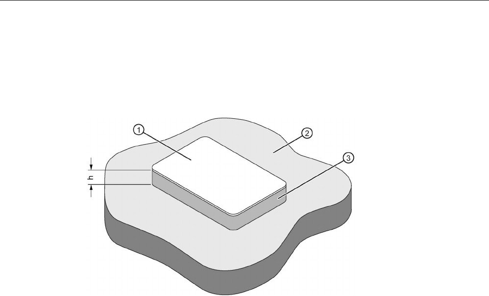
Transponder
7.14 MDS D400
SIMATIC RF200
System Manual, 07/2017, J31069-D0227-U001-A9-7619 265
7.14.3
Mounting on metal
Mounting on metal
It is possible to mount the MDS D400 on metal.
h
≥ 20 mm
①
Transponder
②
Metal
③
Non-metal
Figure 7-33 Mounting of the MDS D400 on metal with spacer

Transponder
7.14 MDS D400
SIMATIC RF200
266 System Manual, 07/2017, J31069-D0227-U001-A9-7619
Flush-mounted in metal
a
≥ 20 mm
h
≥ 20 mm
①
Transponder
②
Metal
③
Non-metal
Figure 7-34 Flush-mounting of MDS D400 in metal with spacer
Note
If the minimum guide values (h) are not observed, this will
result in a reduction of the field
data.
7.14.4
Technical specifications
Table 7- 36 Technical specifications for MDS D400
6GT2600-4AD00
Product type designation
SIMATIC MDS D400
Memory
Memory configuration
• UID • 8 bytes
• User memory • 2000 bytes FRAM

Transponder
7.14 MDS D400
SIMATIC RF200
System Manual, 07/2017, J31069-D0227-U001-A9-7619 267
6GT2600-4AD00
• OTP memory • 16 bytes FRAM
Read cycles (at < 25 ℃)
> 10
12
Write cycles (at < 25 ℃)
> 10
12
Data retention time (at < 25 ℃)
> 10 years
Write/read distance (Sg) Dependent on the reader used, see section "Field
data (Page 39)"
MTBF (Mean Time Between Failures)
228 years
Mechanical specifications
Housing
• Material • PVC
• Color • White
Recommended distance to metal
≥ 20 mm
Power supply
Inductive, without battery
Permitted ambient conditions
Ambient temperature
• during write/read access • -20 to +60 ℃
• outside the read/write field • -20 to +60 ℃
• during storage • -20 to +60 ℃
Degree of protection to EN 60529
IP67
Vibration-resistant to EN 60721-3-7, class 7M3
ISO 10373 / ISO 7810
1)
Torsion and bending load
ISO 10373/ISO 7816-1
Design, dimensions and weight
Dimensions (L x W x H)
85 x 54 x 0.8 mm
Weight
5 g
Type of mounting • Fixing lug
• Glued 2)
1)
The values for vibration are maximum values and must not be applied continuously.
2) The processing instructions of the adhesive manufacturer must be observed.
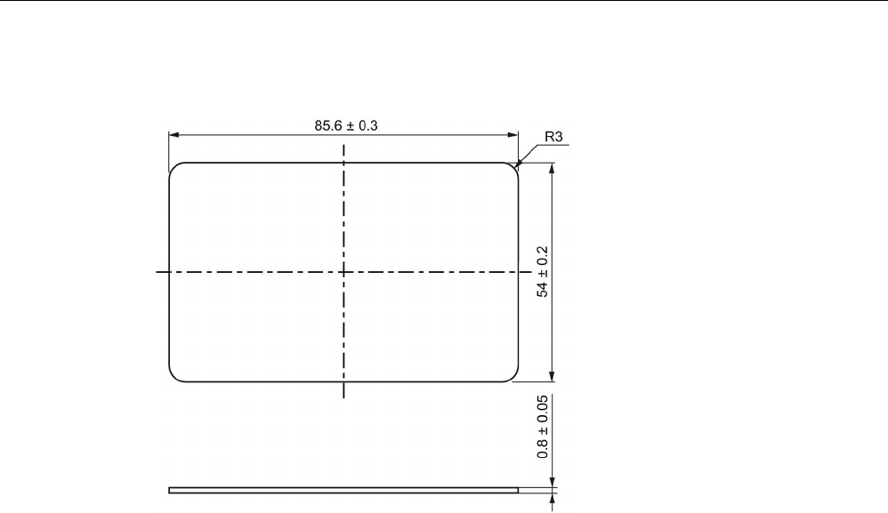
Transponder
7.14 MDS D400
SIMATIC RF200
268 System Manual, 07/2017, J31069-D0227-U001-A9-7619
7.14.5
Dimension drawing
Figure 7-35 Dimensional drawing MDS D400 (dimensions in mm)
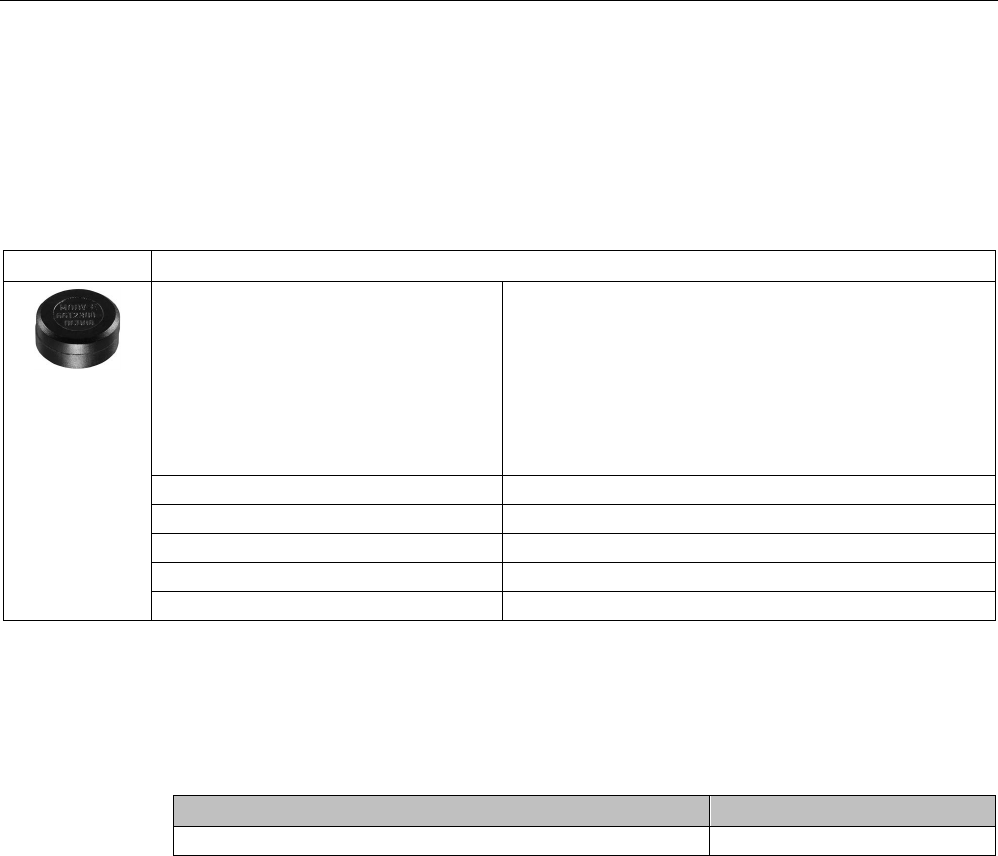
Transponder
7.15 MDS D421
SIMATIC RF200
System Manual, 07/2017, J31069-D0227-U001-A9-7619 269
7.15
MDS D421
7.15.1
Characteristics
MDS D421
Characteristics
Area of application The MDS D421 is designed for tool coding in accordance
with DIN 69873.
It can be used wherever small data carriers and exact posi-
tioning are required, e.g. tool identification, workpiece hold-
ers.
The rugged housing of the MDS D421 means that it can
also be used in a harsh industrial environment without prob-
lems.
Memory size
2000 bytes of FRAM user memory
Write/read range
See section "Field data (Page 39)"
Mounting on metal
Yes, flush-mounted in metal
ISO standard
ISO 15693
Degree of protection
IP67/IPx9K
7.15.2
Ordering data
Table 7- 37 Ordering data of MDS D421
Article number
MDS D421
6GT2600-4AE00
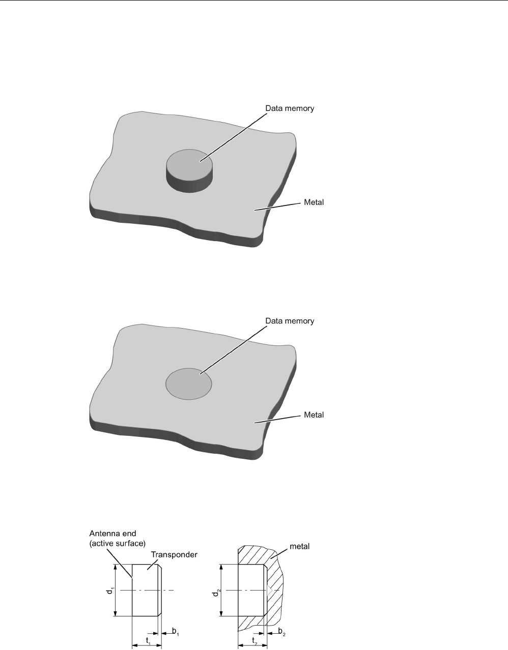
Transponder
7.15 MDS D421
SIMATIC RF200
270 System Manual, 07/2017, J31069-D0227-U001-A9-7619
7.15.3
Mounting on metal
Mounting on metal
Figure 7-36 Mounting of MDS D421 on metal
Flush-mounting
Figure 7-37 Mounting of MDS D421 in metal
Flush-mounting of MDS D421 in metal with tools
Figure 7-38 Flush-mounting of MDS D421 in metal with tools
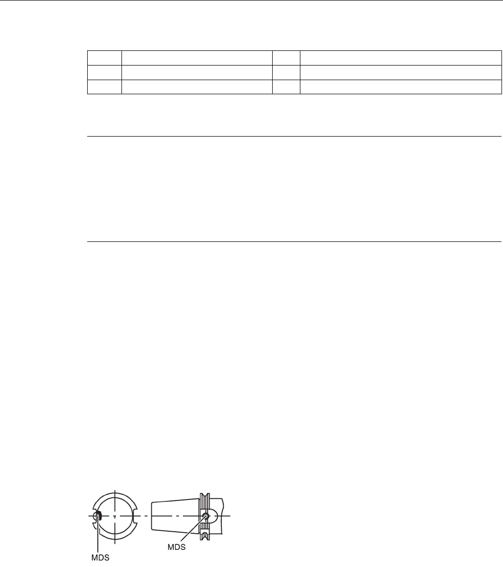
Transponder
7.15 MDS D421
SIMATIC RF200
System Manual, 07/2017, J31069-D0227-U001-A9-7619 271
b
1
0.5 x 45°
b
2
0.3 x 45° or R 0.3
d
1
10 (-0.04.. -0.13)
d
2
10 (+0.09... 0)
t1 4.5 (-0... -0.1) t2 4.6 (+0.2... 0)
All dimensions in mm
Note
Installation instruction
The MDS should not protrude out of the locating hole; it must be flush with the outside
contour.
The mounting instructions of the MDS and the conditions associated with the application
(e.g. peripheral speed, temperature, and use of coolant) must be observed during the
installation.
Mounting information for adhesion
● Drill installation hole
● The adhesive surfaces must be dry, free from dust, oil, stripping agents and other
impurities
● Apply adhesive according to the manufacturer's processing instructions
● Press in MDS D421 using your finger; antenna side to the outside (see figure "Flush-
mounting of MDS D421 in metal with tools")
● Remove residues of adhesive
● Allow to cure according to the manufacturer's instructions
● Flush-mounting of MDS D421 in metal with tools
Installation examples
Figure 7-39 Installation example of MDS D421 in a steep cone
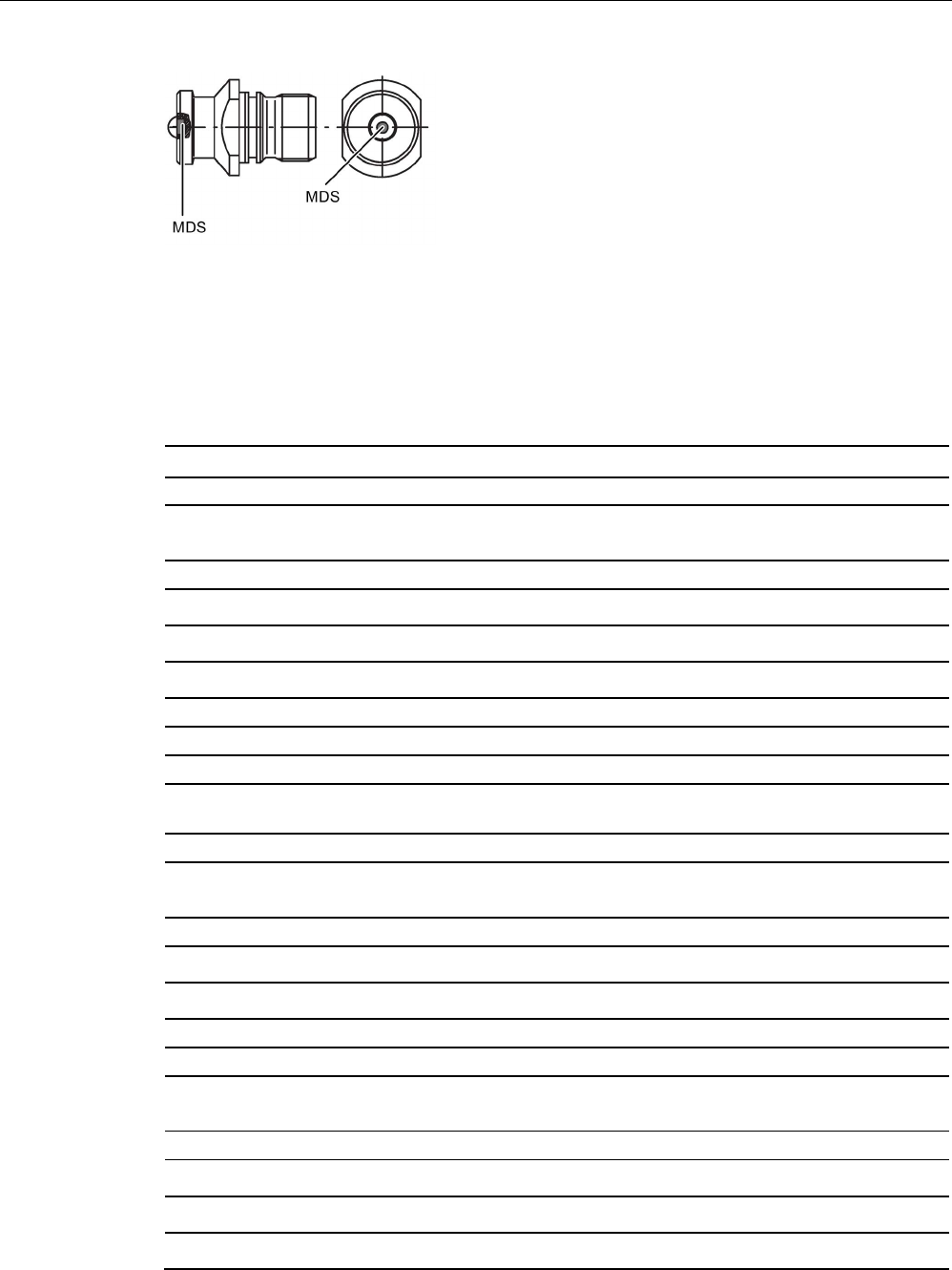
Transponder
7.15 MDS D421
SIMATIC RF200
272 System Manual, 07/2017, J31069-D0227-U001-A9-7619
Figure 7-40 Installation example of MDS D421 in a stud bolt
7.15.4
Technical specifications
Table 7- 38 Technical specifications for the MDS D421
6GT2600-4AE00
Product type designation SIMATIC MDS D421
Memory
Memory configuration
• UID • 8 bytes
• User memory • 2000 bytes FRAM
• OTP memory • 16 bytes FRAM
Read cycles (at < 40 ℃)
> 10
12
Write cycles (at < 40 ℃)
> 10
12
Data retention time (at < 40 ℃)
> 10 years
Write/read distance (Sg) Dependent on the reader used, see section "Field
data (Page 39)"
MTBF (Mean Time Between Failures)
228 years
Mechanical specifications
Housing
• Material • Epoxy resin
• Color • Black
Recommended distance to metal
≥ 0 mm
Power supply
Inductive, without battery
Permitted ambient conditions
Ambient temperature
• during write/read access • -25 to +85 ℃
• outside the read/write field • -40 to +100 ℃
• during storage • -40 to +100 ℃
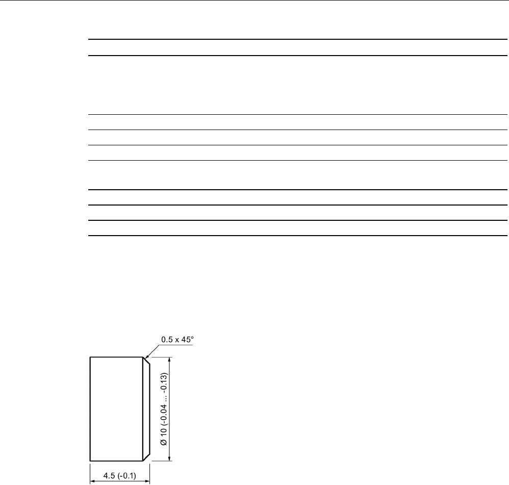
Transponder
7.15 MDS D421
SIMATIC RF200
System Manual, 07/2017, J31069-D0227-U001-A9-7619 273
6GT2600-4AE00
Degree of protection to EN 60529 • IP67
• IPx9K
steam jet: 150 mm; 10 to 15 l/min; 100 bar; 75
°C
Shock according to EN 60721-3-7 Class 7M3
1)
1000 m/s
2
Vibration according to EN 60721-3-7 Class 7M3
1)
200 m/s
2
Torsion and bending load
Not permitted
Design, dimensions and weight
Dimensions (Ø x H)
10 x 4.5 mm
Weight
Approx. 1 g
Type of mounting
Glued
2)
1)
The values for shock and vibration are maximum values and must not be applied continuously.
2) The processing instructions of the adhesive manufacturer must be observed.
7.15.5
Dimension drawing
Figure 7-41 Dimension drawing of MDS D421
All dimensions in mm
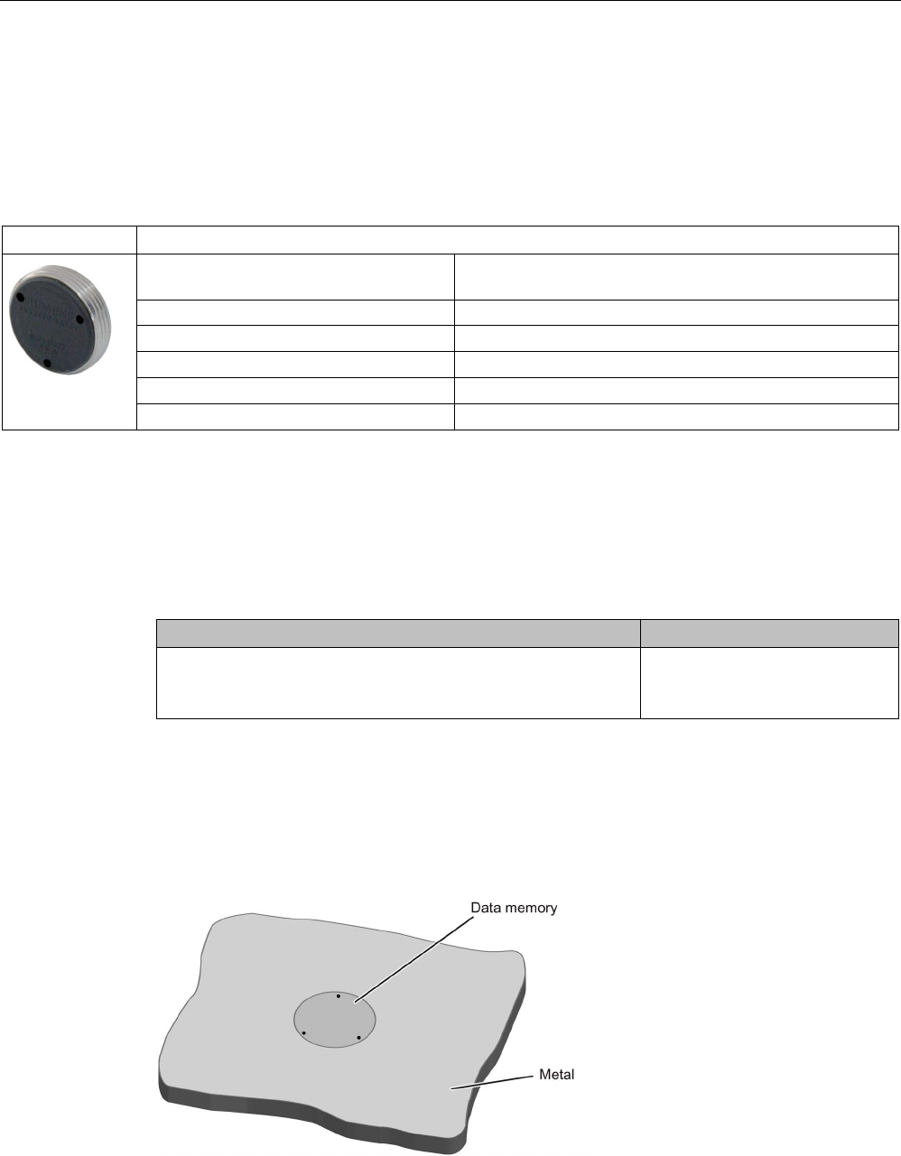
Transponder
7.16 MDS D422
SIMATIC RF200
274 System Manual, 07/2017, J31069-D0227-U001-A9-7619
7.16
MDS D422
7.16.1
Characteristics
MDS D422
Characteristics
Area of application Identification of metallic workpiece holders, workpieces or
containers
Memory size
2000 bytes of FRAM user memory
Write/read range
See section "Field data (Page 39).
Mounting on metal Yes
ISO standard
ISO 15693
Degree of protection
IP68
7.16.2
Ordering data
Table 7- 39 Ordering data of MDS D422
Article number
MDS D422
A screw-in aid is included in the scope of supply per packaging
unit
6GT2600-4AF00
7.16.3
Mounting in metal
Flush-mounting
Figure 7-42 Mounting of MDS D422 in metal

Transponder
7.16 MDS D422
SIMATIC RF200
System Manual, 07/2017, J31069-D0227-U001-A9-7619 275
Mounting information for screws
You can screw the transponder into a pre-drilled threaded hole using the screw-in aid.
Mounting information for adhesion
● Drill installation hole
● The adhesive surfaces must be dry, free from dust, oil, stripping agents and other
impurities
● Apply adhesive according to the manufacturer's processing instructions
● Press in MDS D422 using your fingers; with antenna to the outside
● Remove residues of adhesive
● Allow to cure according to the manufacturer's instructions
● Flush-mounting of MDS D422 in metal with tools
7.16.4
Technical specifications
Table 7- 40 Technical specifications for the MDS D422
6GT2600-4AF00
Product type designation
SIMATIC MDS D422
Memory
Memory configuration
• UID • 8 bytes
• User memory • 2000 bytes FRAM
• OTP memory • 16 bytes FRAM
Read cycles (at < 40 ℃)
> 10
12
Write cycles (at < 40 ℃)
> 10
12
Data retention time (at < 40 ℃)
> 10 years
Write/read distance (Sg) Dependent on the reader used, see section "Field
data (Page 39)"
MTBF (Mean Time Between Failures)
285 years
Mechanical specifications
Housing
• Material • Plastic PA 6.6 GF; brass nickel plated
• Color • Black/silver
Recommended distance to metal
≥ 0 mm
Power supply
Inductive, without battery
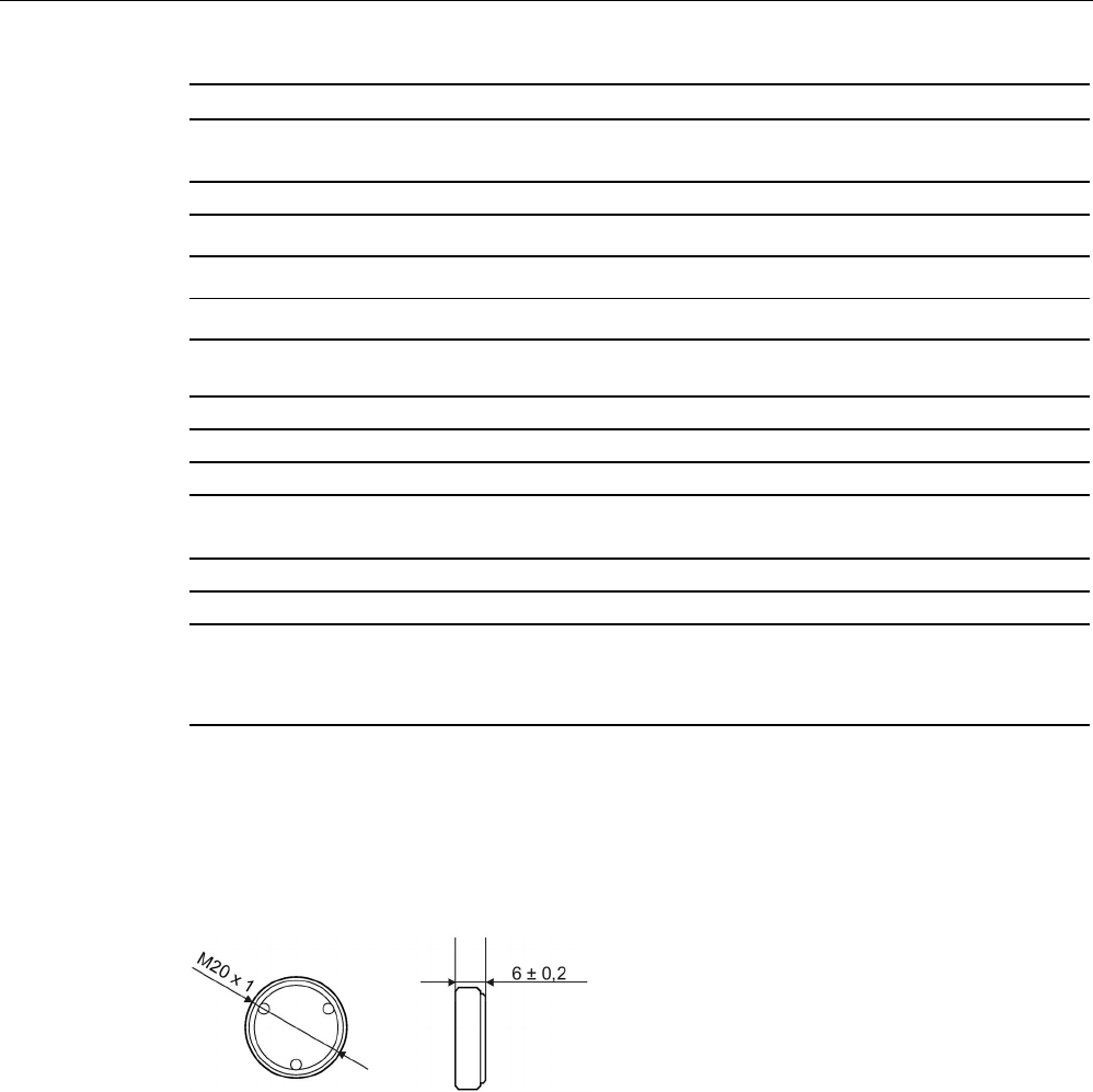
Transponder
7.16 MDS D422
SIMATIC RF200
276 System Manual, 07/2017, J31069-D0227-U001-A9-7619
6GT2600-4AF00
Permitted ambient conditions
Ambient temperature
• during write/read access • -25 to +85 ℃
• outside the read/write field • -40 to +100 ℃
• during storage • -40 to +100 ℃
Degree of protection to EN 60529 IP68
2 hours, 2 bar, +20 °C
Shock according to EN 60721-3-7 Class 7M3
1)
500 m/s
2
Vibration according to EN 60721-3-7 Class 7M3
1)
200 m/s
2
Torsion and bending load
Not permitted
Design, dimensions and weight
Dimensions (Ø x H)
20 x 6 mm
Weight
13 g
Type of mounting • Glued 2)
• 1 x transponder thread M20
≤ 1 Nm
1)
The values for shock and vibration are maximum values and must not be applied continuously.
2) The processing instructions of the adhesive manufacturer must be observed.
7.16.5
Dimension drawing
Dimensions in mm
Figure 7-43 Dimensional drawing of MDS D422
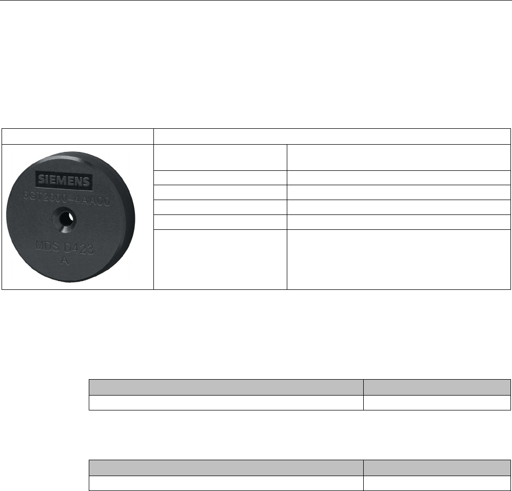
Transponder
7.17 MDS D423
SIMATIC RF200
System Manual, 07/2017, J31069-D0227-U001-A9-7619 277
7.17
MDS D423
7.17.1
Characteristics
MDS D423
Characteristics
Area of application Identification of metallic workpiece holders, work-
pieces or containers, production automation
Memory size
2000 bytes of FRAM user memory
Write/read range
See section "Field data (Page 39)"
Mounting on metal Yes, flush-mounted in metal
ISO standard
ISO 15693
Degree of protection IP68/IPx9K
7.17.2
Ordering data
Table 7- 41 Ordering data of MDS D423
Article number
MDS D423 6GT2600-4AA00
Table 7- 42 Ordering data of MDS D423 accessories
Article number
Fixing hood RF330T / MDS D423
6GT2690-0AE00
7.17.3
Mounting on metal
Mounting on metal
Direct mounting of the MDS D423 on metal is possible.
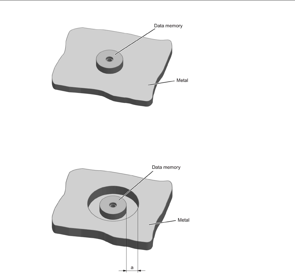
Transponder
7.17 MDS D423
SIMATIC RF200
278 System Manual, 07/2017, J31069-D0227-U001-A9-7619
Figure 7-44 Mounting the MDS D423 on metal
Flush-mounted in metal
It is possible to mount the MDS D423 in metal.
a
≥ 10 mm
Figure 7-45 Flush-mounting of the MDS D423 in metal with 10 mm clearance
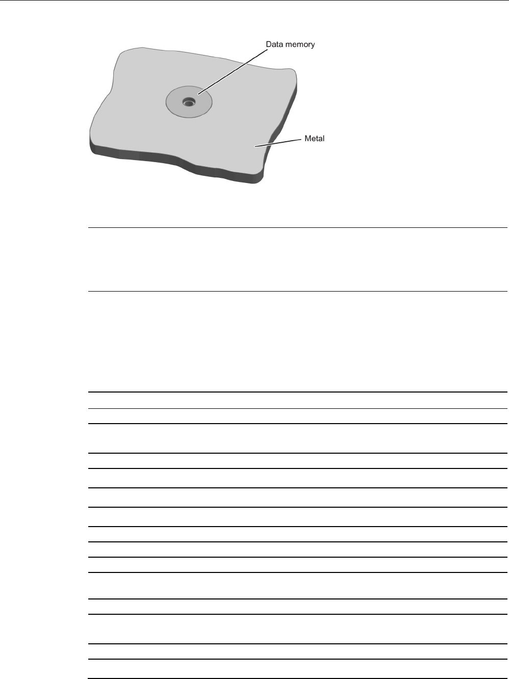
Transponder
7.17 MDS D423
SIMATIC RF200
System Manual, 07/2017, J31069-D0227-U001-A9-7619 279
Figure 7-46 Flush-mounting of the MDS D423 in metal without clearance
Note
Reduction of the write/read range
Note that when the device is flush
-mounted in metal without a surrounding clearance ≥ 10
mm, the write/read range is significantly reduced.
7.17.4
Technical specifications
Table 7- 43 Technical specifications of MDS D423
6GT2600-4AA00
Product type designation
SIMATIC MDS D423
Memory
Memory configuration
• UID • 8 bytes
• User memory • 2000 bytes FRAM
• OTP memory • 16 bytes FRAM
Read cycles (at < 40 ℃)
> 10
12
Write cycles (at < 40 ℃)
> 10
12
Data retention time (at < 40 ℃)
> 10 years
Write/read distance (Sg) Dependent on the reader used, see section "Field
data (Page 39)"
MTBF (Mean Time Between Failures)
228 years
Mechanical specifications
Housing
• Material • Plastic PPS

Transponder
7.17 MDS D423
SIMATIC RF200
280 System Manual, 07/2017, J31069-D0227-U001-A9-7619
6GT2600-4AA00
• Color • Black
Recommended distance to metal
≥ 0 mm
Power supply
Inductive, without battery
Permitted ambient conditions
Ambient temperature
• during write/read access • -25 to +85 ℃
• outside the read/write field • -40 to +100 ℃
• during storage • -40 to +100 ℃
Degree of protection to EN 60529 • IP68
2 hours, 2 bar, +20 °C
• IPx9K
steam jet: 150 mm; 10 to 15 l/min; 100 bar; 75
°C
Shock according to EN 60721-3-7 Class 7M3
1)
500 m/s
2
Vibration according to EN 60721-3-7 Class 7M3
1)
200 m/s
2
Pressure resistance • Low pressure resistant
vacuum dryer: up to 20 mbar
• High pressure resistant
(see degree of protection IPx9K)
Torsion and bending load
Not permitted
Design, dimensions and weight
Dimensions (Ø x H)
30 x 8 mm
Weight
15 g
Type of mounting 1 x M4 screw 2)
≤ 1 Nm
1)
The values for shock and vibration are maximum values and must not be applied continuously.
2 ) To prevent it loosening during operation, secure the screw with screw locking varnish.
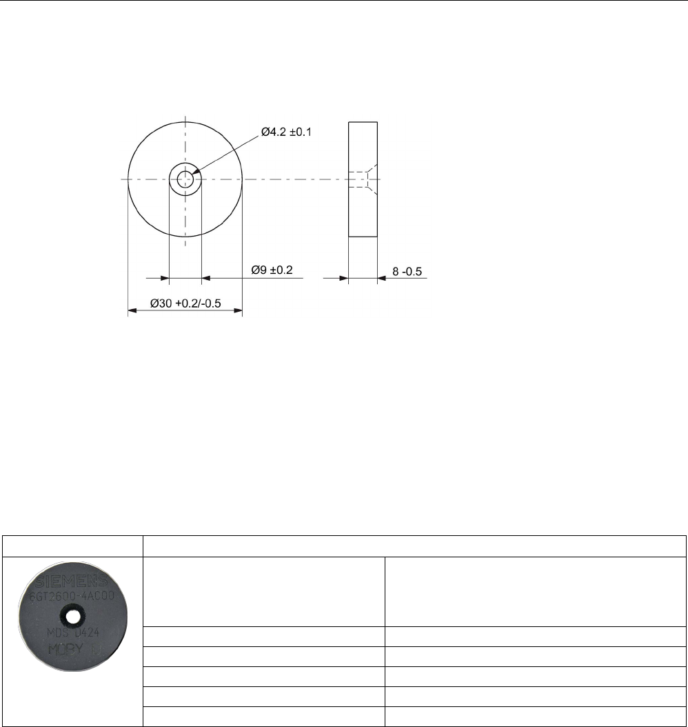
Transponder
7.18 MDS D424
SIMATIC RF200
System Manual, 07/2017, J31069-D0227-U001-A9-7619 281
7.17.5
Dimensional drawing
Dimensions in mm
Figure 7-47 Dimension drawing for MDS D423
7.18
MDS D424
7.18.1
Characteristics
MDS D424
Characteristics
Area of application Production and distribution logistics as well as in
assembly and production lines,
can also be used in a harsh industrial environment
without problem
Memory size
2000 bytes of FRAM user memory
Write/read range
See section "Field data (Page 39)."
Mounting on metal
Yes, with spacer
ISO standard
ISO 15693
Degree of protection
IP67; IPx9K
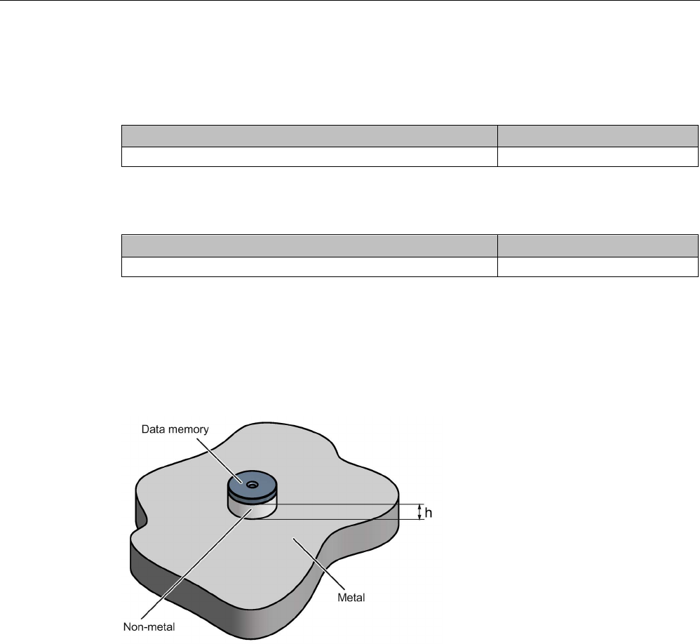
Transponder
7.18 MDS D424
SIMATIC RF200
282 System Manual, 07/2017, J31069-D0227-U001-A9-7619
7.18.2
Ordering data
Table 7- 44 Ordering data of MDS D424
Article number
MDS D424
6GT2600-4AC00
Table 7- 45 Ordering data of MDS D424 accessories
Article number
Spacer
6GT2690-0AK00
7.18.3
Mounting on metal
Mounting on metal
h
≥ 15 mm
Figure 7-48 Mounting the MDS D124/D324/D424/D524/E624 and RF320T on metal with spacer
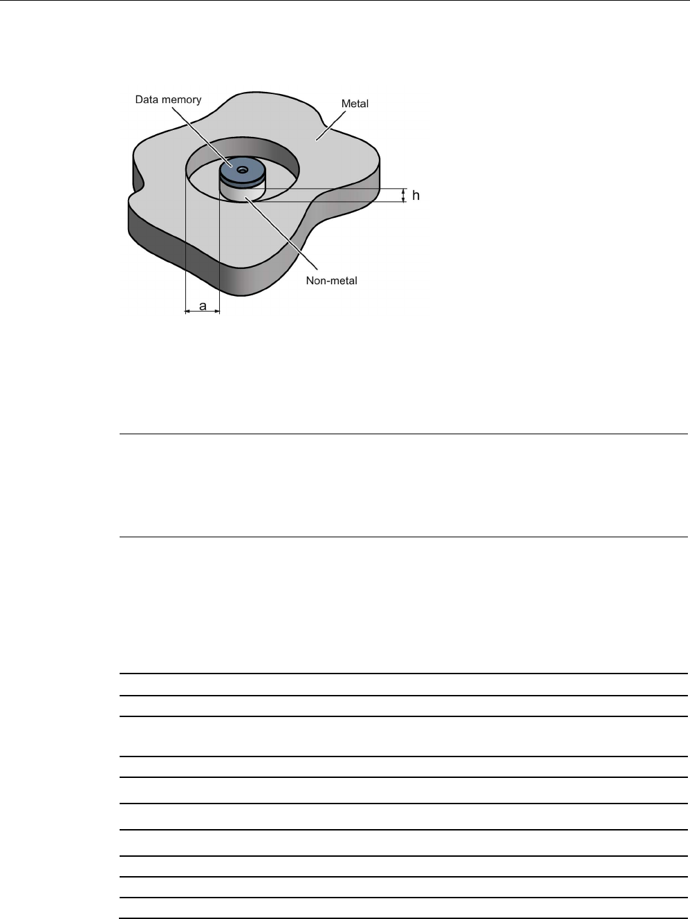
Transponder
7.18 MDS D424
SIMATIC RF200
System Manual, 07/2017, J31069-D0227-U001-A9-7619 283
Flush-mounting
h
≥ 15 mm
a
≥ 25 mm
Figure 7-49 Flush-mounting of the MDS D124/D324/D424/D524/E624 and RF320T in metal with
spacer
Note
Going below the distances
If the distances (a and h) are not observed,
a reduction of the field data results. It is possible
to mount the MDS with metal screws (M3 countersunk head screws). This has no tangible
impact on the range.
7.18.4
Technical specifications
Table 7- 46 Technical specifications for the MDS D424
6GT2600-4AC00
Product type designation
SIMATIC MDS D424
Memory
Memory configuration
• UID • 8 bytes
• User memory • 2000 bytes FRAM
• OTP memory • 16 bytes FRAM
Read cycles (at < 40 ℃)
> 10
12
Write cycles (at < 40 ℃)
> 10
12
Data retention time (at < 40 ℃)
> 10 years

Transponder
7.18 MDS D424
SIMATIC RF200
284 System Manual, 07/2017, J31069-D0227-U001-A9-7619
6GT2600-4AC00
Write/read distance (Sg) Dependent on the reader used, see section "Field
data (Page 39)"
MTBF (Mean Time Between Failures)
228 years
Mechanical specifications
Housing
• Material • Epoxy resin
• Color • Black
Recommended distance to metal
≥ 15 mm
Power supply
Inductive, without battery
Permitted ambient conditions
Ambient temperature
• during write/read access • -25 to +85 ℃
• outside the read/write field • -40 to +100 ℃
• during storage • -40 to +100 ℃
Degree of protection to EN 60529 • IP67
• IPx9K
Shock according to EN 60721-3-7 Class 7M3
1)
1000 m/s
2
Vibration according to EN 60721-3-7 Class 7M3
1)
200 m/s
2
Torsion and bending load
Not permitted
Design, dimensions and weight
Dimensions (Ø x H)
27 x 4 mm
Weight
5 g
Type of mounting • Glued 2)
• 1x screw M3 3)
≤ 1 Nm
1)
The values for shock and vibration are maximum values and must not be applied continuously.
2)
The processing instructions of the adhesive manufacturer must be observed.
3 ) To prevent it loosening during operation, secure the screw with screw-locking varnish.
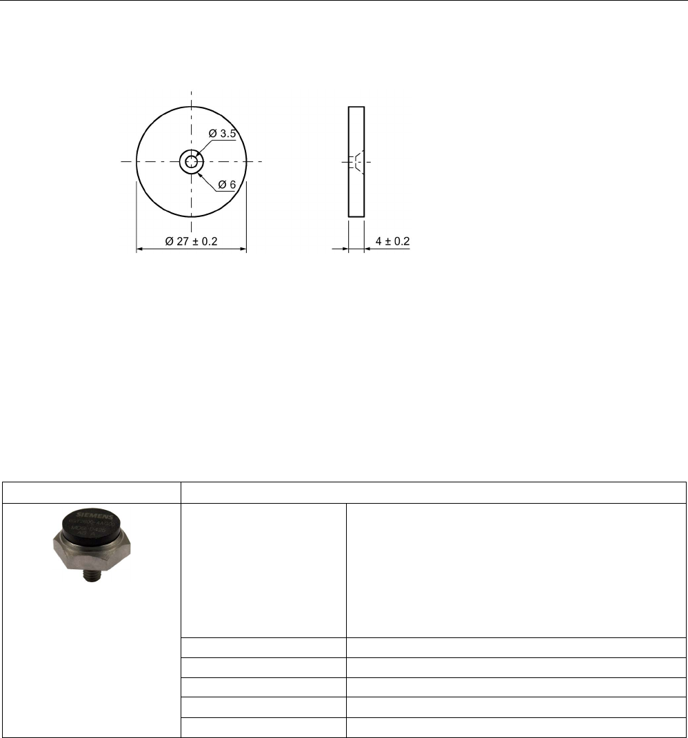
Transponder
7.19 MDS D425
SIMATIC RF200
System Manual, 07/2017, J31069-D0227-U001-A9-7619 285
7.18.5
Dimension drawing
Figure 7-50 Dimension drawing of MDS D424
All dimensions in mm
7.19
MDS D425
7.19.1
Characteristics
MDS D425
Characteristics
Area of application Compact and rugged ISO transponder; suitable for screw
mounting
Use in assembly and production lines in the powertrain
sector; ideal for mounting on motors, gearboxes, and work-
piece holders
Rugged packaging of the MDS D425; can therefore also be
used under extreme environmental conditions without prob-
lem
Memory size
2000 bytes of FRAM user memory
Write/read range
See section "Field data (Page 39)".
Mounting on metal
Yes
ISO standard
ISO 15693
Degree of protection
IP68/IPx9K
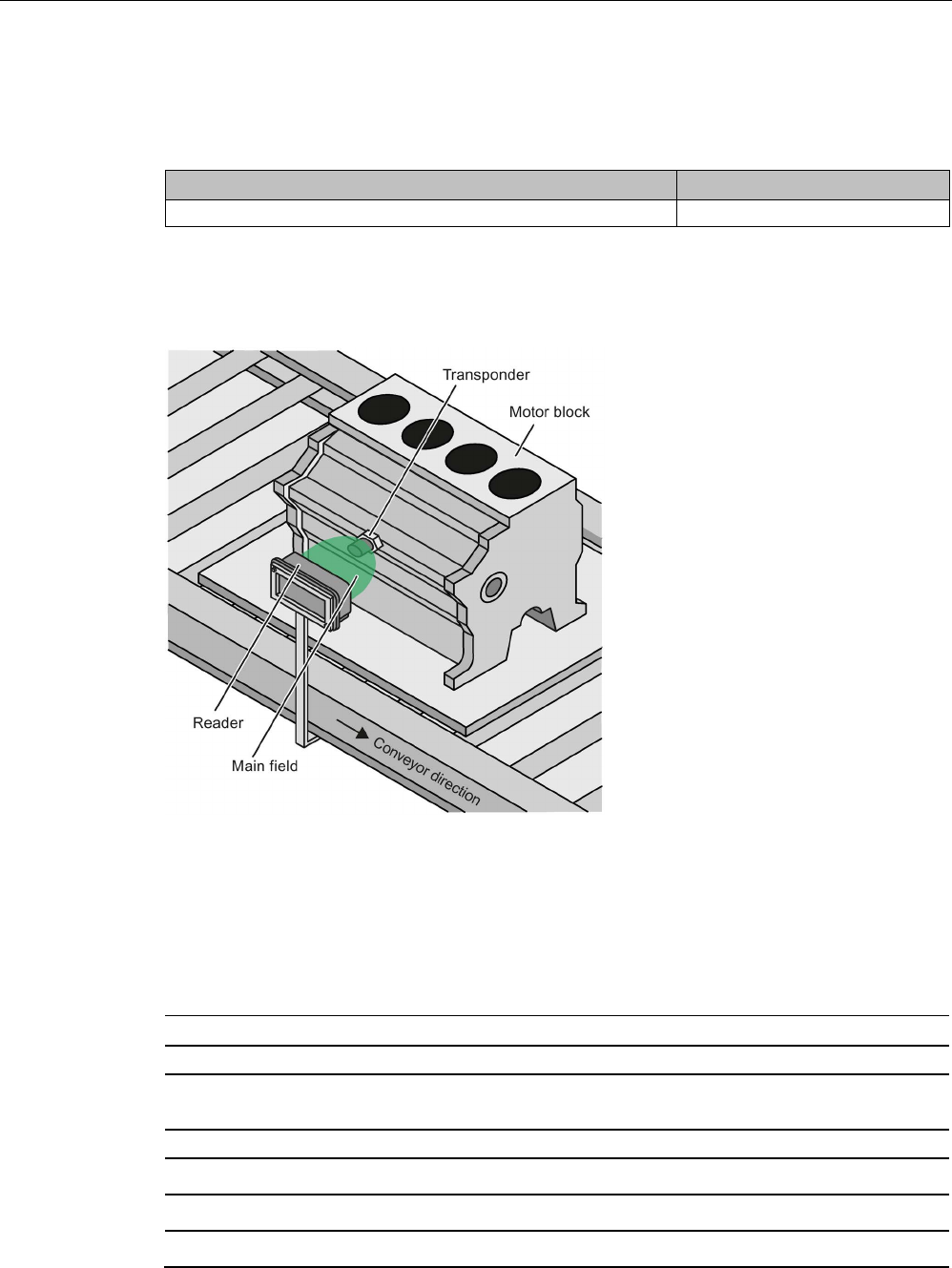
Transponder
7.19 MDS D425
SIMATIC RF200
286 System Manual, 07/2017, J31069-D0227-U001-A9-7619
7.19.2
Ordering data
Table 7- 47 Ordering data of MDS D425
Article number
MDS D425
6GT2600-4AG00
7.19.3
Application example
Figure 7-51 Application example
7.19.4
Technical specifications
Table 7- 48 Technical specifications for the MDS D425
6GT2600-4AG00
Product type designation
SIMATIC MDS D425
Memory
Memory configuration
• UID • 8 bytes
• User memory • 2000 bytes FRAM
• OTP memory • 16 bytes FRAM

Transponder
7.19 MDS D425
SIMATIC RF200
System Manual, 07/2017, J31069-D0227-U001-A9-7619 287
6GT2600-4AG00
Read cycles (at < 40 ℃)
> 10
12
Write cycles (at < 40 ℃)
> 10
12
Data retention time (at < 40 ℃)
> 10 years
Write/read distance (Sg) Dependent on the reader used, see section "Field
data (Page 39)"
MTBF (Mean Time Between Failures)
228 years
Mechanical specifications
Housing
• Material • Plastic PA 6.6 GF
• Color • Black
Recommended distance to metal
≥ 0 mm
Power supply
Inductive, without battery
Permitted ambient conditions
Ambient temperature
• during write/read access • -25 to +85 ℃
• outside the read/write field • -40 to +125 ℃
• during storage • -40 to +125 ℃
Degree of protection to EN 60529 • IP68
2 hours, 2 bar, +20 °C
• IPx9K
steam jet: 150 mm; 10 to 15 l/min; 100 bar; 75
°C
Shock according to IEC 68-2-27
1)
500 m/s
2
Vibration according to IEC 68-2-6
1)
200 m/s
2
Torsion and bending load
Not permitted
Design, dimensions and weight
Dimensions (Ø x H)
24 x 10 mm (without set screw)
Weight
35 g
Type of mounting 1x transponder set screw M6
SW 22; ≤ 6 Nm
1) The values for shock and vibration are maximum values and must not be applied continuously.
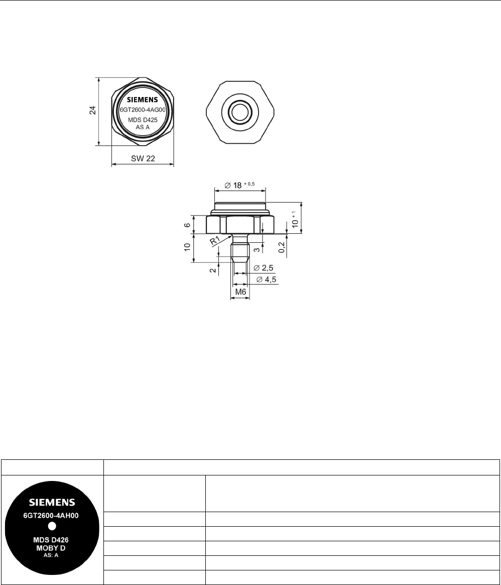
Transponder
7.20 MDS D426
SIMATIC RF200
288 System Manual, 07/2017, J31069-D0227-U001-A9-7619
7.19.5
Dimension drawing
Dimensions in mm
Figure 7-52 Dimension drawing of MDS D425
7.20
MDS D426
7.20.1
Characteristics
MDS D426
Characteristics
Area of application Compact and rugged ISO transponder; suitable for identification of
transport units in production-related logistics; can also be deployed in
harsh conditions
Memory size
2000 bytes of FRAM user memory
Write/read range
See section Field data (Page 39)
Mounting on metal
Yes, with spacer
ISO standard
ISO 15693
Degree of protection
IP68

Transponder
7.20 MDS D426
SIMATIC RF200
System Manual, 07/2017, J31069-D0227-U001-A9-7619 289
7.20.2
Mounting on metal
Mounting on metal
h
≥ 25 mm
Figure 7-53 Mounting the MDS D126 / D426 / D526 on metal with spacer
Flush-mounted in metal
h
≥ 25 mm
a
≥ 50 mm
Figure 7-54 Flush installation of the MDS D126 / D426 / D526 in metal with spacer
Transponder
7.20 MDS D426
SIMATIC RF200
290 System Manual, 07/2017, J31069-D0227-U001-A9-7619
7.20.3
Ordering data
Table 7- 49 Ordering data of MDS D426
Article number
MDS D426
6GT2600-4AH00
Table 7- 50 Ordering data of MDS D426 accessories
Article number
Spacer
6GT2690-0AL00
7.20.4
Technical specifications
Table 7- 51 Technical specifications for the MDS D426
6GT2600-4AH00
Product type designation
SIMATIC MDS D426
Memory
Memory configuration
• UID • 8 bytes
• User memory • 2000 bytes FRAM
• OTP memory • 16 bytes FRAM
Read cycles (at < 40 ℃)
> 10
12
Write cycles (at < 40 ℃)
> 10
12
Data retention time (at < 40 ℃)
> 10 years
Write/read distance (Sg) Dependent on the reader used, see section "Field
data (Page 39)"
MTBF (Mean Time Between Failures)
228 years
Mechanical specifications
Housing
• Material • Plastic PA 6.6 GF
• Color • Black
Recommended distance to metal
≥ 25 mm
Power supply
Inductive, without battery
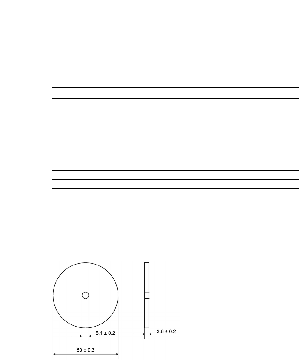
Transponder
7.20 MDS D426
SIMATIC RF200
System Manual, 07/2017, J31069-D0227-U001-A9-7619 291
6GT2600-4AH00
Permitted ambient conditions
Ambient temperature
• during write/read access • -25 to +85 ℃
• outside the read/write field • -40 to +100 ℃
• during storage • -40 to +100 ℃
Degree of protection to EN 60529 IP68
2 hours, 2 bar, +20 °C
Shock according to IEC 68-2-27
1)
50 m/s
2
Vibration according to IEC 68-2-6
1)
20 m/s
2
Torsion and bending load
Not permitted
Design, dimensions and weight
Dimensions (Ø x H)
50 x 3.6 mm
Weight
13 g
Type of mounting 1 x M4 screw 2)
≤ 1 Nm
1)
The values for shock and vibration are maximum values and must not be applied continuously.
2 ) To prevent it loosening during operation, secure the screw with screw locking varnish.
7.20.5
Dimension drawing
Dimensions in mm
Figure 7-55 Dimension drawing of MDS D426
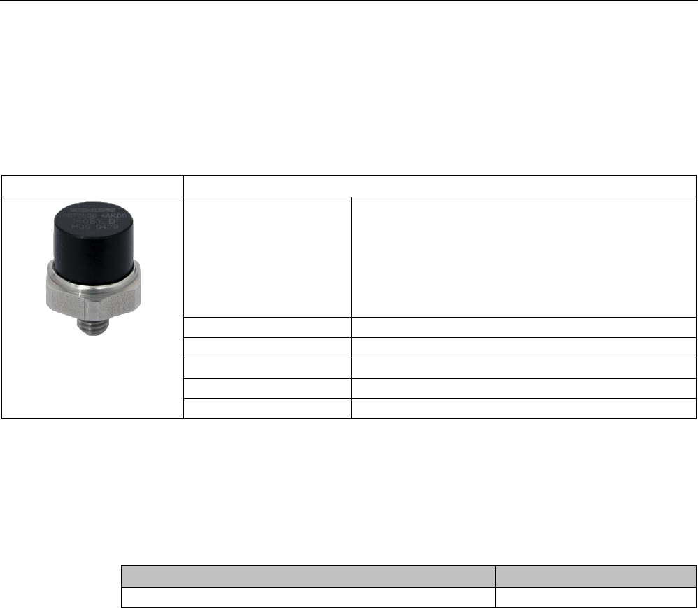
Transponder
7.21 MDS D428
SIMATIC RF200
292 System Manual, 07/2017, J31069-D0227-U001-A9-7619
7.21
MDS D428
7.21.1
Characteristics
MDS D428
Characteristics
Area of application Compact and rugged ISO transponder; suitable for screw
mounting.
Use in assembly and production lines in the powertrain
sector.
The rugged housing of the MDS D428 means that it can
also be used in extreme environmental conditions without
problems.
Memory size
2000 bytes of FRAM user memory
Write/read range
See section "Field data (Page 39)"
Mounting on metal
Yes
ISO standard
ISO 15693
Degree of protection
IP68/IPx9K
7.21.2
Ordering data
Table 7- 52 Ordering data of MDS D428
Article number
MDS D428
6GT2600-4AK00-0AX0
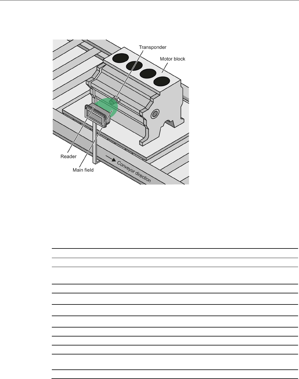
Transponder
7.21 MDS D428
SIMATIC RF200
System Manual, 07/2017, J31069-D0227-U001-A9-7619 293
7.21.3
Application example
Figure 7-56 Application example
7.21.4
Technical specifications
Table 7- 53 Technical specifications for the MDS D428
6GT2600-4AK00
Product type designation SIMATIC MDS D428
Memory
Memory configuration
• UID • 8 bytes
• User memory • 2000 bytes FRAM
• OTP memory • 16 bytes FRAM
Read cycles (at < 40 ℃) > 1012
Write cycles (at < 40 ℃)
> 10
12
Data retention time (at < 40 ℃)
> 10 years
Write/read distance (Sg) Dependent on the reader used, see section "Field
data (Page 39)"
MTBF (Mean Time Between Failures)
228 years

Transponder
7.21 MDS D428
SIMATIC RF200
294 System Manual, 07/2017, J31069-D0227-U001-A9-7619
6GT2600-4AK00
Mechanical specifications
Housing
• Material • Plastic PA 6.6 GF
• Color • Black
Recommended distance to metal
≥ 0 mm
Power supply
Inductive, without battery
Permitted ambient conditions
Ambient temperature
• during write/read access • -25 to +85 ℃
• outside the read/write field • -40 to +125 ℃
• during storage • -40 to +125 ℃
Degree of protection to EN 60529 • IP68
2 hours, 2 bar, +20 °C
• IPx9K
steam jet: 150 mm; 10 to 15 l/min; 100 bar; 75
°C
Shock according to IEC 68-2-27
1)
500 m/s
2
Vibration according to IEC 68-2-6
1)
200 m/s
2
Torsion and bending load
Not permitted
Design, dimensions and weight
Dimensions (Ø x H)
24 x 20 mm (without set screw)
Weight
35 g
Type of mounting 1x transponder set screw M8
SW 22; ≤ 8 Nm
1) The values for shock and vibration are maximum values and must not be applied continuously.
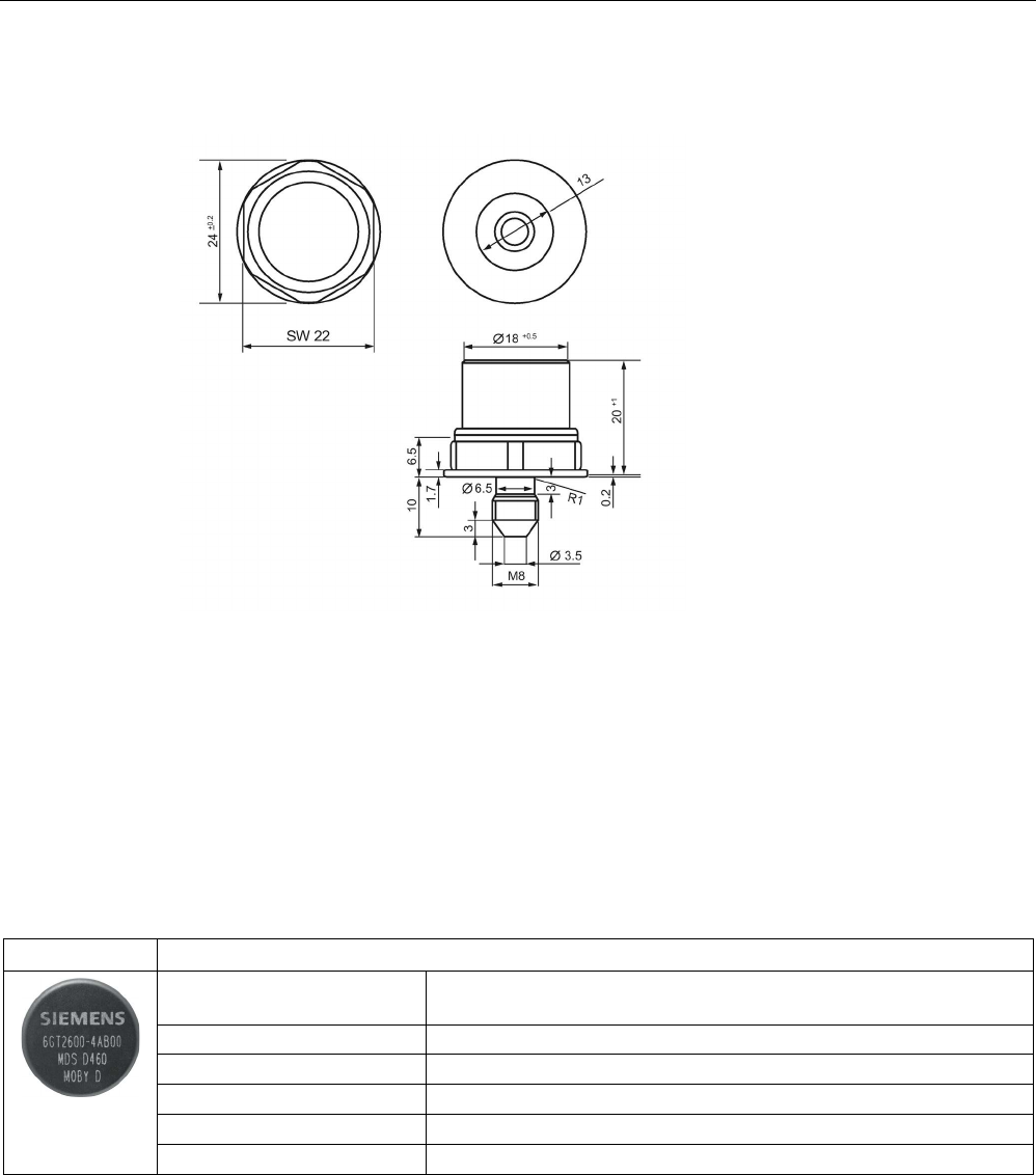
Transponder
7.22 MDS D460
SIMATIC RF200
System Manual, 07/2017, J31069-D0227-U001-A9-7619 295
7.21.5
Dimension drawing
Dimensions in mm
Figure 7-57 Dimension drawing of MDS D428
7.22
MDS D460
7.22.1
Characteristics
MDS D460
Characteristics
Area of application Identification in small assembly lines; can also be used in a harsh in-
dustrial environment
Memory size
2000 bytes of FRAM user memory
Write/read range
See section "Field data (Page 39).
Mounting on metal
Yes, with spacer
ISO standard
ISO 15693
Degree of protection
IP67/IPx9K
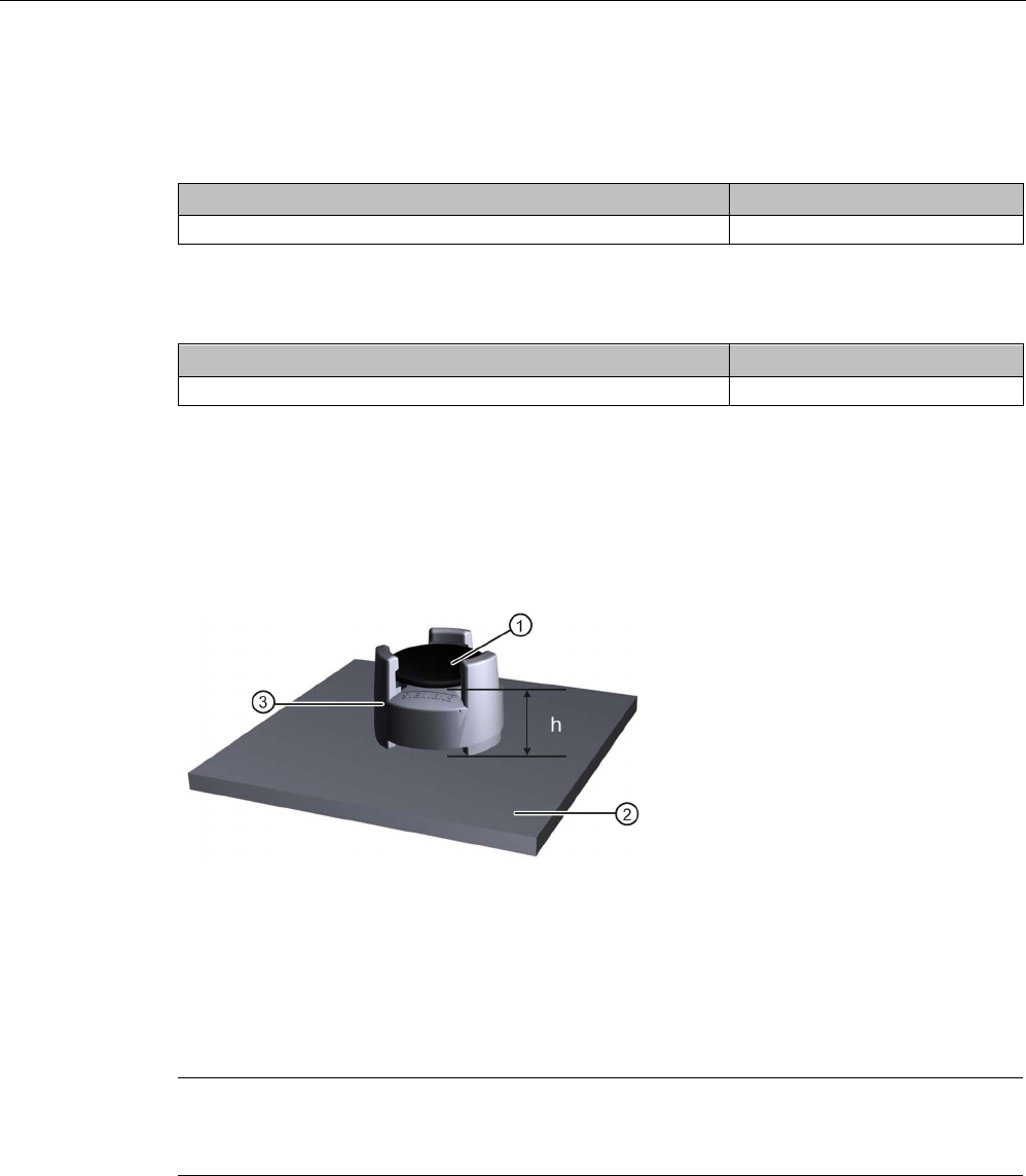
Transponder
7.22 MDS D460
SIMATIC RF200
296 System Manual, 07/2017, J31069-D0227-U001-A9-7619
7.22.2
Ordering data
Table 7- 54 Ordering data of MDS D460
Article number
MDS D460
6GT2600-4AB00
Table 7- 55 Ordering data of MDS D460 accessories
Article number
Spacer
6GT2690-0AG00
7.22.3
Mounting on metal
Mounting option on metal with spacer
①
Transponder
②
Metal
③
Spacer
h
≥ 10 mm
Figure 7-58 Mounting the MDS D460 on metal with spacer
Note
If the minimum guide values (h) are not observed, a reduction of the field data results.
In critical applications, it is recommended that a test is performed.
Flush-mounting
Flush-mounting of the MDS D460 in metal is not permitted!

Transponder
7.22 MDS D460
SIMATIC RF200
System Manual, 07/2017, J31069-D0227-U001-A9-7619 297
7.22.4
Technical specifications
Table 7- 56 Technical specifications for MDS D460
6GT2600-4AB00
Product type designation
SIMATIC MDS D460
Memory
Memory configuration
• UID • 8 bytes
• User memory • 2000 bytes FRAM
• OTP memory • 16 bytes FRAM
Read cycles (at < 40 ℃)
> 10
12
Write cycles (at < 40 ℃)
> 10
12
Data retention time (at < 40 ℃)
> 10 years
Write/read distance (Sg) Dependent on the reader used, see section "Field
data (Page 39)"
MTBF (Mean Time Between Failures)
228 years
Mechanical specifications
Housing
• Material • Epoxy resin
• Color • Black
Recommended distance to metal
≥ 10 mm
Power supply
Inductive, without battery
Permitted ambient conditions
Ambient temperature
• during write/read access • -25 to +85 ℃
• outside the read/write field • -40 to +100 ℃
• during storage • -40 to +100 ℃
Degree of protection to EN 60529 • IP67
• IPx9K
steam jet: 150 mm; 10 to 15 l/min; 100 bar; 75
°C
Shock according to IEC 68-2-27
1)
500 m/s
2
Vibration according to IEC 68-2-6
1)
200 m/s
2
Torsion and bending load
Not permitted
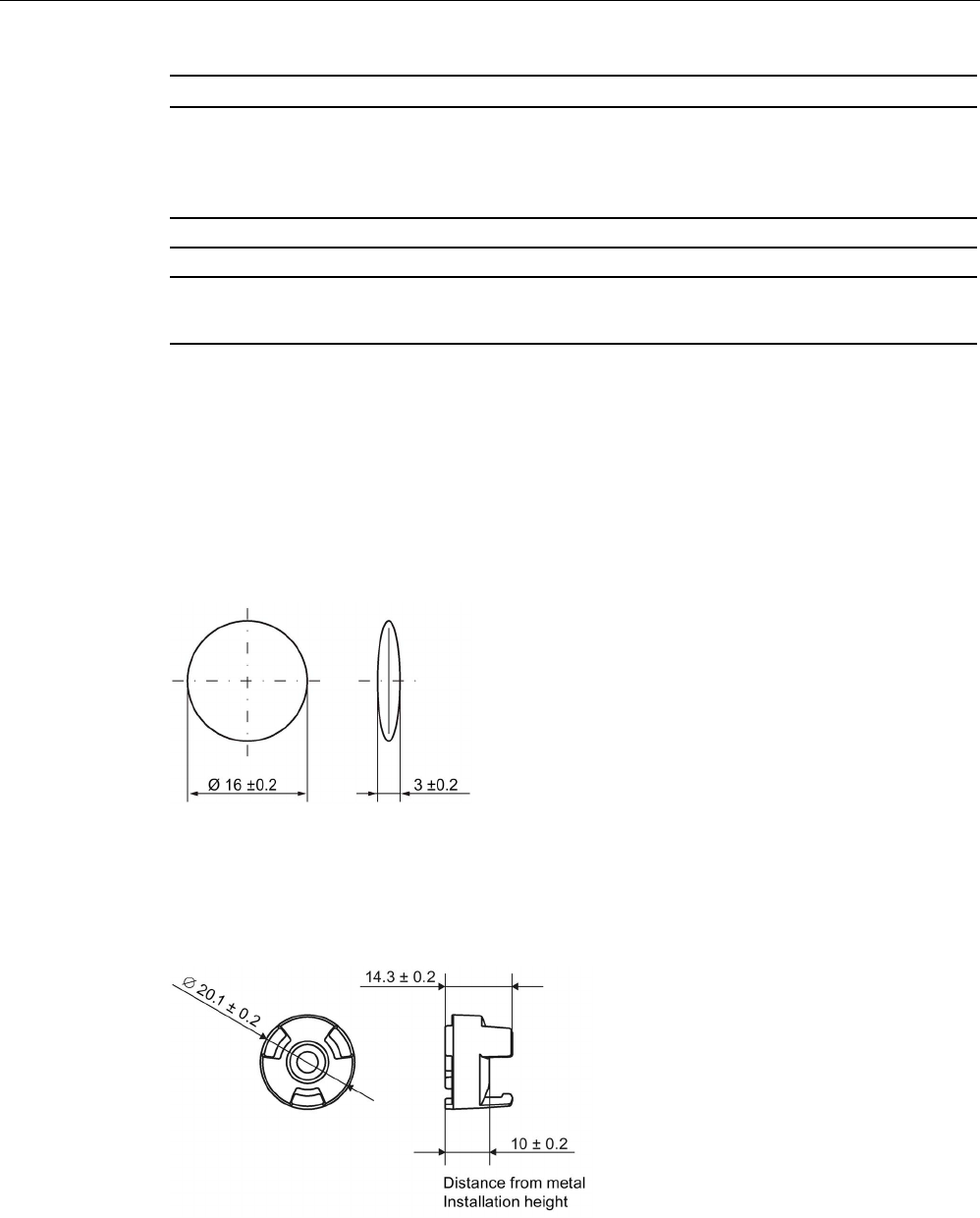
Transponder
7.22 MDS D460
SIMATIC RF200
298 System Manual, 07/2017, J31069-D0227-U001-A9-7619
6GT2600-4AB00
Design, dimensions and weight
Dimensions (Ø x H)
16 x 3 mm
Weight
3 g
Type of mounting • Glued 2)
• With spacer
1)
The values for shock and vibration are maximum values and must not be applied continuously.
2) The processing instructions of the adhesive manufacturer must be observed.
7.22.5
Dimension drawings
Dimensional drawing of MDS D460
Dimensions in mm
Figure 7-59 Dimensional drawing of MDS D460
Dimensional drawing of spacer
Dimensions in mm
Figure 7-60 Dimensional drawing of spacer
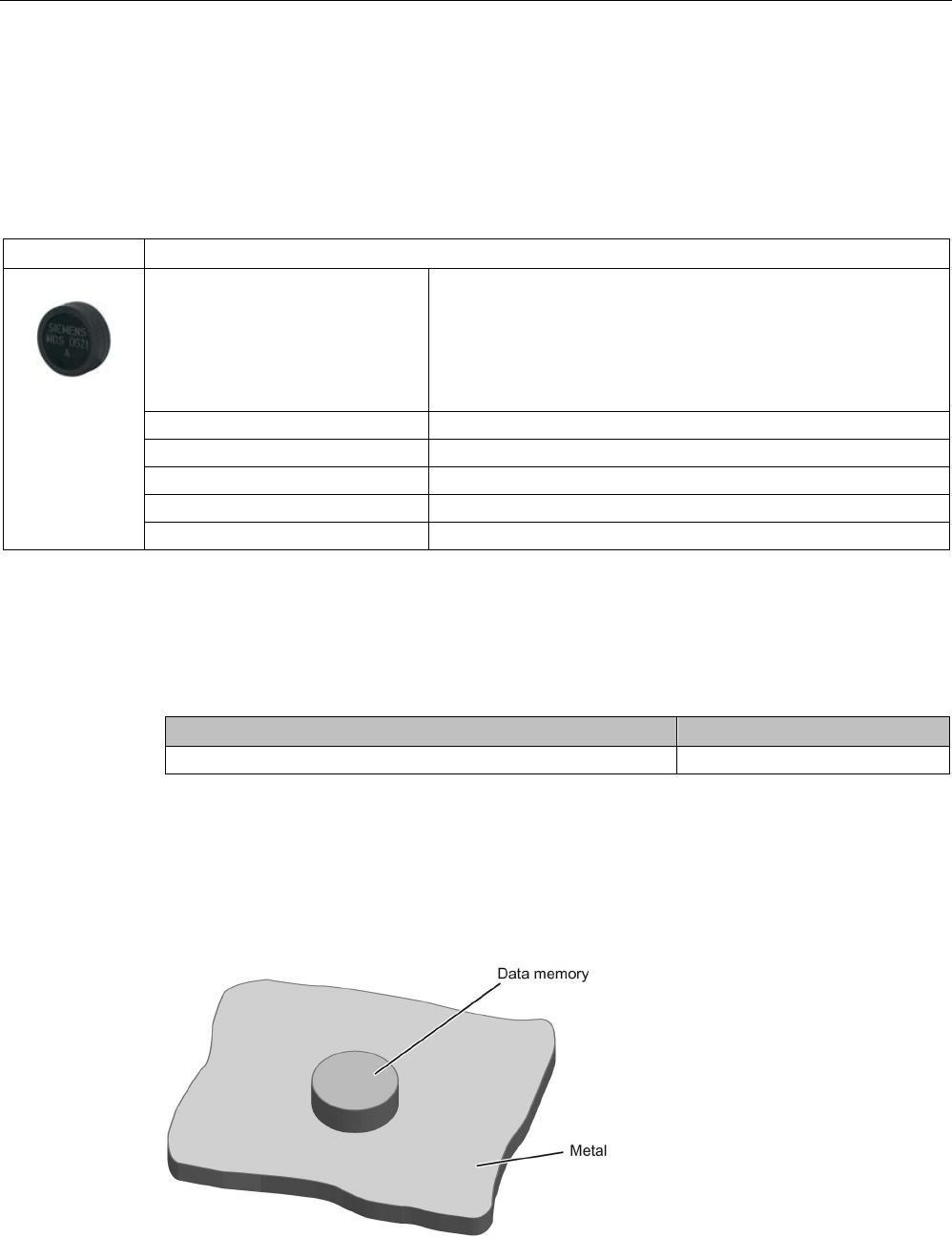
Transponder
7.23 MDS D521
SIMATIC RF200
System Manual, 07/2017, J31069-D0227-U001-A9-7619 299
7.23
MDS D521
7.23.1
Characteristics
MDS D521
Characteristics
Area of application The MDS D521 is designed for tool coding according to DIN
69873.
It can be used wherever small data carriers and exact positioning
are required, e.g. tool identification, workpiece holders.
The rugged housing of the MDS D521 means that it can also be
used in a harsh industrial environment without problems.
Memory size
8192 bytes of FRAM user memory
Write/read range
See section "Field data (Page 39)"
Mounting on metal
Yes, flush-mounted in metal
ISO standard
ISO 15693
Degree of protection
IP67/IPx9K
7.23.2
Ordering data
Table 7- 57 Ordering data for MDS D521
Article number
MDS D521
6GT2600-5AE00
7.23.3
Mounting on metal
Mounting on metal
Figure 7-61 Mounting of MDS D521 on metal
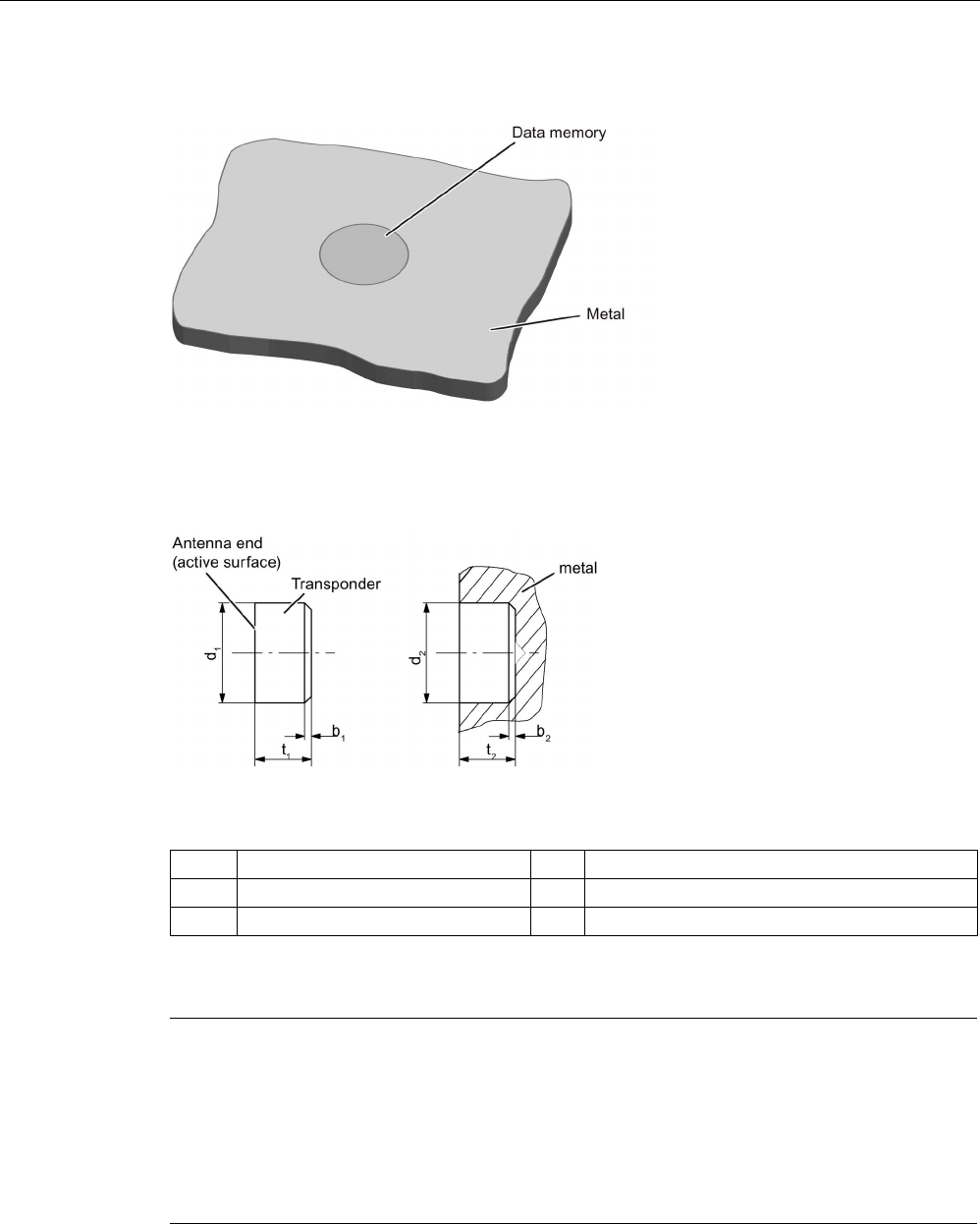
Transponder
7.23 MDS D521
SIMATIC RF200
300 System Manual, 07/2017, J31069-D0227-U001-A9-7619
Flush-mounting
Figure 7-62 Mounting of MDS D521 in metal
Flush-mounting of MDS D521 in metal with tools
Figure 7-63 Flush-mounting of MDS D521 in metal with tools
b1
0.5 x 45°
b2
0.3 x 45° or R 0.3
d
1
10 (-0.04.. -0.13)
d
2
10 (+0.09... 0)
t1
4.5 (-0... -0.1)
t2
4.6 (+0.2... 0)
All dimensions in mm
Note
Installation instruction
The MDS should not protrude out of the locating hole; it must be flush with the outside
contour.
The mounting instructions of the MDS and the conditions associated wi
th the application
(e.g. peripheral speed, temperature, and use of coolant) must be observed during the
installation.
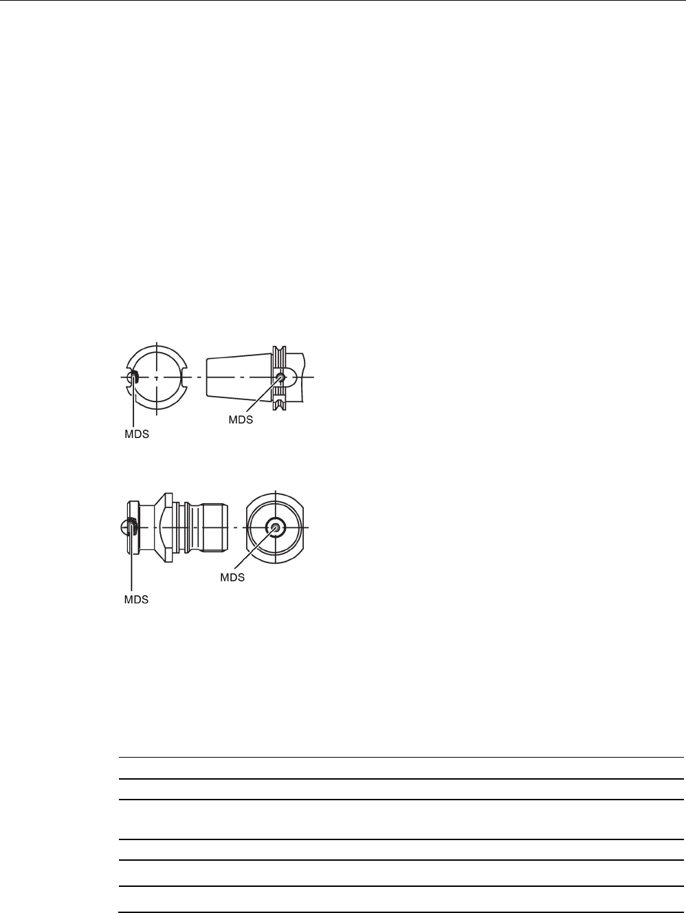
Transponder
7.23 MDS D521
SIMATIC RF200
System Manual, 07/2017, J31069-D0227-U001-A9-7619 301
Mounting information for adhesion
● Drill installation hole
● The adhesive surfaces must be dry, free from dust, oil, stripping agents and other
impurities
● Apply adhesive according to the manufacturer's processing instructions
● Press in MDS D521 using your finger; antenna side to the outside (see figure "Flush-
mounting of MDS D521 in metal with tools")
● Remove residues of adhesive
● Allow to cure according to the manufacturer's instructions
● Flush-mounting of MDS D521 in metal with tools
Installation examples
Figure 7-64 Installation example of MDS D521 in a steep cone
Figure 7-65 Installation example of MDS D521 in a stud bolt
7.23.4
Technical specifications
Table 7- 58 Technical specifications for MDS D521
6GT2600-5AE00
Product type designation
SIMATIC MDS D521
Memory
Memory configuration
• UID • 8 bytes
• User memory • 8192 bytes FRAM

Transponder
7.23 MDS D521
SIMATIC RF200
302 System Manual, 07/2017, J31069-D0227-U001-A9-7619
6GT2600-5AE00
Read cycles (at < 40 ℃)
> 10
12
Write cycles (at < 40 ℃)
> 10
12
Data retention time (at < 40 ℃)
> 10 years
Write/read distance (Sg) Dependent on the reader used, see section "Field
data (Page 39)"
MTBF (Mean Time Between Failures)
228 years
Mechanical specifications
Housing
• Material • Epoxy resin
• Color • Black
Recommended distance to metal
≥ 0 mm
Power supply
Inductive, without battery
Permitted ambient conditions
Ambient temperature
• during write/read access • -25 to +85 ℃
• outside the read/write field • -40 to +100 ℃
• during storage • -40 to +100 ℃
Degree of protection to EN 60529 • IP67
• IPx9K
steam jet: 150 mm; 10 to 15 l/min; 100 bar; 75
°C
Shock according to EN 60721-3-7 Class 7M3
1)
1000 m/s
2
Vibration according to EN 60721-3-7 Class 7M3
1)
200 m/s
2
Torsion and bending load
Not permitted
Design, dimensions and weight
Dimensions (Ø x H)
10 x 4.5 mm
Weight
1 g
Type of mounting
Glued
2)
1)
The values for shock and vibration are maximum values and must not be applied continuously.
2) The processing instructions of the adhesive manufacturer must be observed.
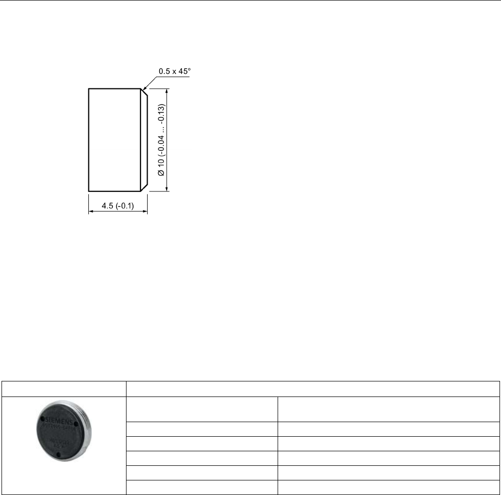
Transponder
7.24 MDS D522
SIMATIC RF200
System Manual, 07/2017, J31069-D0227-U001-A9-7619 303
7.23.5
Dimension drawing
Figure 7-66 Dimension drawing of MDS D521
All dimensions in mm
7.24
MDS D522
7.24.1
Characteristics
MDS D522
Characteristics
Area of application Identification of metallic workpiece holders, work-
pieces or containers
Memory size 8192 bytes of FRAM user memory
Write/read range
See "Field data (Page 39)."
Mounting in metal
Yes
ISO standard
ISO 15693
Degree of protection
IP68
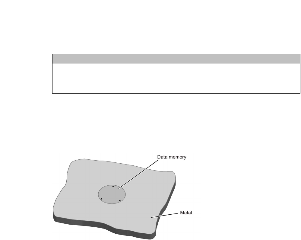
Transponder
7.24 MDS D522
SIMATIC RF200
304 System Manual, 07/2017, J31069-D0227-U001-A9-7619
7.24.2
Ordering data
Table 7- 59 Ordering data for MDS D522
Article number
MDS D522
Units in a package: 10 units
A mounting aid is included in the scope of supply per packaging
unit.
6GT2600-5AF00
7.24.3
Mounting in metal
Flush-mounting
Figure 7-67 Mounting of MDS D522 in metal
Mounting information for screws
You can screw the transponder into a pre-drilled threaded hole using the screw-in aid.
Mounting information for adhesion
● Drill installation hole
● The adhesive surfaces must be dry, free from dust, oil, stripping agents and other
impurities
● Apply adhesive according to the manufacturer's processing instructions
● Press in MDS D522 using your fingers; with antenna to the outside
● Remove residues of adhesive
● Allow to cure according to the manufacturer's instructions
● Flush-mounting of MDS D522 in metal with tools

Transponder
7.24 MDS D522
SIMATIC RF200
System Manual, 07/2017, J31069-D0227-U001-A9-7619 305
7.24.4
Technical specifications
Table 7- 60 Technical specifications for MDS D522
6GT2600-5AF00
Product type designation
SIMATIC MDS D522
Memory
Memory configuration
• UID • 8 bytes
• User memory • 8192 bytes FRAM
Read cycles (at < 40 ℃)
> 10
12
Write cycles (at < 40 ℃)
> 10
12
Data retention time (at < 40 ℃)
> 10 years
Write/read distance (Sg) Dependent on the reader used, see section "Field
data (Page 39)"
MTBF (Mean Time Between Failures)
285 years
Mechanical specifications
Housing
• Material • Plastic PA 6.6 GF; brass nickel plated
• Color • Black/silver
Recommended distance to metal
≥ 0 mm
Power supply
Inductive, without battery
Permitted ambient conditions
Ambient temperature
• during write/read access • -25 to +85 ℃
• outside the read/write field • -40 to +100 ℃
• during storage • -40 to +100 ℃
Degree of protection to EN 60529 IP68
2 hours, 2 bar, +20 °C
Shock according to EN 60721-3-7 Class 7M3
1)
500 m/s
2
Vibration according to EN 60721-3-7 Class 7M3
1)
200 m/s
2
Torsion and bending load Not permitted
Design, dimensions and weight
Dimensions (Ø x H) 20 x 6 mm
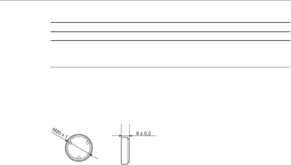
Transponder
7.24 MDS D522
SIMATIC RF200
306 System Manual, 07/2017, J31069-D0227-U001-A9-7619
6GT2600-5AF00
Weight
13 g
Type of mounting • Glued 2)
• 1 x transponder thread M20
≤ 1 Nm
1)
The values for shock and vibration are maximum values and must not be applied continuously.
2) The processing instructions of the adhesive manufacturer must be observed.
7.24.5
Dimension drawing
Figure 7-68 Dimensional drawing of MDS D522
All dimensions in mm
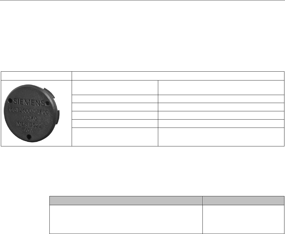
Transponder
7.25 MDS D522 special variant
SIMATIC RF200
System Manual, 07/2017, J31069-D0227-U001-A9-7619 307
7.25
MDS D522 special variant
7.25.1
Characteristics
MDS D522 special version
Characteristics
Area of application Identification of metallic workpiece holders or work-
pieces
Memory size
8192 bytes of FRAM user memory
Write/read range
See "Field data (Page 39)."
Mounting in metal Yes
ISO standard
ISO 15693
Degree of protection IP68
7.25.2
Ordering data
Table 7- 61 MDS D522 special version
Article number
MDS D522 special version
Units in a package: 10 units
A mounting aid is included in the scope of supply per packaging
unit.
6GT2600-5AF00-0AX0
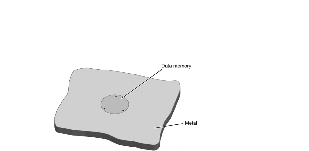
Transponder
7.25 MDS D522 special variant
SIMATIC RF200
308 System Manual, 07/2017, J31069-D0227-U001-A9-7619
7.25.3
Mounting in metal
Flush-mounting
Figure 7-69 Flush installation of the MDS D522 special version in metal without clearance
7.25.4
Installation instructions
The transponder MDS D522 special version is designed to be mounted once.
Note the following instructions when mounting the MDS D522 in a workpiece to avoid
damaging the transponder:
● Prepare the workpiece according to the following drawing.
● Using the accompanying mounting aid, press the transponder with uniform and evenly
distributed pressure into the drilled hole until the transponder locks in place. Make sure
that the transponder does not become tilted.
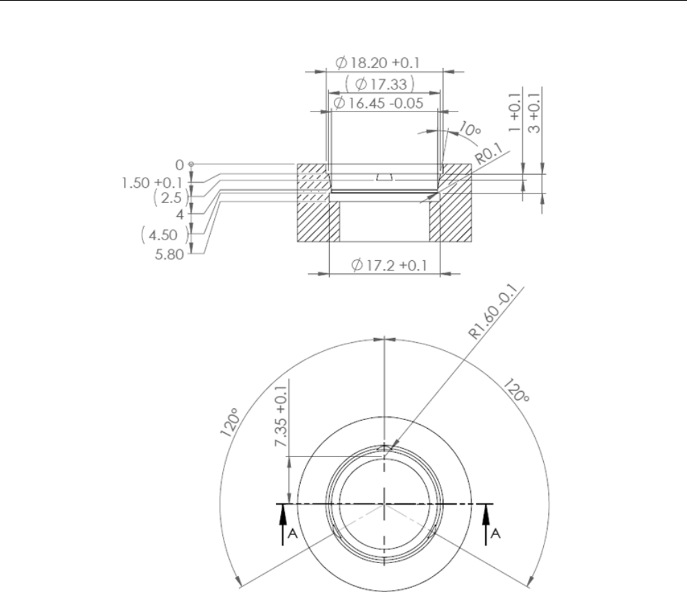
Transponder
7.25 MDS D522 special variant
SIMATIC RF200
System Manual, 07/2017, J31069-D0227-U001-A9-7619 309
Figure 7-70 Dimension drawing: Workpiece drill hole for mounting the MDS D522 special version

Transponder
7.25 MDS D522 special variant
SIMATIC RF200
310 System Manual, 07/2017, J31069-D0227-U001-A9-7619
7.25.5
Technical specifications
Table 7- 62 Technical data of MDS D522 special version
6GT2600-5AF00-0AX0
Product type designation
SIMATIC MDS D522 special version
Memory
Memory configuration
• UID • 8 bytes
• User memory • 8192 bytes FRAM
Read cycles (at < 40 ℃)
> 10
12
Write cycles (at < 40 ℃)
> 10
12
Data retention time (at < 40 ℃)
> 10 years
Write/read distance (Sg) Dependent on the reader used, see section "Field
data (Page 39)"
MTBF (Mean Time Between Failures)
228 years
Mechanical specifications
Housing
• Material • Plastic PA 6.6 GF
• Color • Black
Recommended distance to metal
≥ 0 mm
Power supply
Inductive, without battery
Permitted ambient conditions
Ambient temperature
• during write/read access • -25 to +85 ℃
• outside the read/write field • -40 to +100 ℃
• during storage • -40 to +100 ℃
Degree of protection to EN 60529 IP68
2 hours, 2 bar, +20 °C
Shock according to EN 60721-3-7 Class 7M3
1)
500 m/s
2
Vibration according to EN 60721-3-7 Class 7M3
1)
200 m/s
2
Torsion and bending load Not permitted
Design, dimensions and weight
Dimensions (Ø x H) 18 (+0.1) × 5.2 mm
Weight
Approx. 1.2 g
Type of mounting
Clipping in once (with accompanying tool)
1) The values for shock and vibration are maximum values and must not be applied continuously.
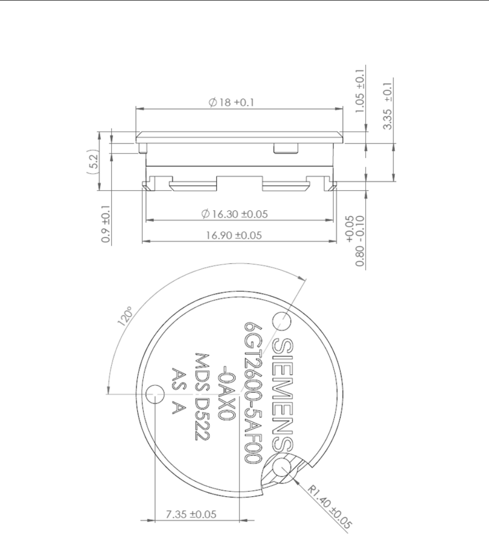
Transponder
7.25 MDS D522 special variant
SIMATIC RF200
System Manual, 07/2017, J31069-D0227-U001-A9-7619 311
7.25.6
Dimensional drawing
Figure 7-71 Dimension drawing MDS D522 special version
All dimensions in mm
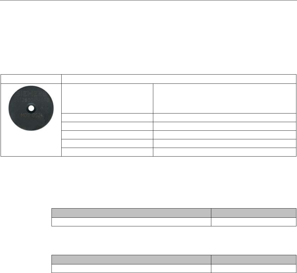
Transponder
7.26 MDS D524
SIMATIC RF200
312 System Manual, 07/2017, J31069-D0227-U001-A9-7619
7.26
MDS D524
7.26.1
Characteristics
MDS D524
Characteristics
Area of application Production and distribution logistics as well as in assem-
bly and production lines,
can also be used in a harsh industrial environment without
problem
Memory size
8192 bytes of FRAM user memory
Write/read range
See section "Field data (Page 39)."
Mounting on metal
Yes, with spacer
ISO standard
ISO 15693
Degree of protection
IP67; IPx9K
7.26.2
Ordering data
Table 7- 63 Ordering data for MDS D524
Article number
MDS D524
6GT2600-5AC00
Table 7- 64 Ordering data of MDS D524 accessories
Article number
Spacer
6GT2690-0AK00

Transponder
7.26 MDS D524
SIMATIC RF200
System Manual, 07/2017, J31069-D0227-U001-A9-7619 313
7.26.3
Mounting on metal
Mounting on metal
h
≥ 15 mm
Figure 7-72 Mounting the MDS D124/D324/D424/D524/E624 and RF320T on metal with spacer
Flush-mounting
h
≥ 15 mm
a
≥ 25 mm
Figure 7-73 Flush-mounting of the MDS D124/D324/D424/D524/E624 and RF320T in metal with
spacer

Transponder
7.26 MDS D524
SIMATIC RF200
314 System Manual, 07/2017, J31069-D0227-U001-A9-7619
Note
Going below the distances
If the distances (a and h) are not observed, a reduction of the field data results. It is possible
to mount the MDS with metal scr
ews (M3 countersunk head screws). This has no tangible
impact on the range.
7.26.4
Technical specifications
Table 7- 65 Technical specifications for MDS D524
6GT2600-5AC00
Product type designation
SIMATIC MDS D524
Memory
Memory configuration
• UID • 8 bytes
• User memory • 8192 bytes FRAM
Read cycles (at < 40 ℃)
> 10
12
Write cycles (at < 40 ℃)
> 10
12
Data retention time (at < 40 ℃)
> 10 years
Write/read distance (Sg) Dependent on the reader used, see section "Field
data (Page 39)"
MTBF (Mean Time Between Failures)
228 years
Mechanical specifications
Housing
• Material • Epoxy resin
• Color • Black
Recommended distance to metal
≥ 15 mm
Power supply
Inductive, without battery
Permitted ambient conditions
Ambient temperature
• during write/read access • -25 to +85 ℃
• outside the read/write field • -40 to +100 ℃
• during storage • -40 to +100 ℃

Transponder
7.26 MDS D524
SIMATIC RF200
System Manual, 07/2017, J31069-D0227-U001-A9-7619 315
6GT2600-5AC00
Degree of protection to EN 60529 • IP67
• IPx9K
Shock according to EN 60721-3-7 Class 7M3
1)
1000 m/s
2
Vibration according to EN 60721-3-7 Class 7M3
1)
200 m/s
2
Torsion and bending load
Not permitted
Design, dimensions and weight
Dimensions (Ø x H)
27 x 4 mm
Weight
5 g
Type of mounting • Glued 2)
• 1x screw M3 3)
≤ 1 Nm
1)
The values for shock and vibration are maximum values and must not be applied continuously.
2)
The processing instructions of the adhesive manufacturer must be observed.
3 ) To prevent it loosening during operation, secure the screw with screw-locking varnish.
7.26.5
Dimension drawing
Figure 7-74 Dimensional drawing of MDS D524
All dimensions in mm

Transponder
7.27 MDS D526
SIMATIC RF200
316 System Manual, 07/2017, J31069-D0227-U001-A9-7619
7.27
MDS D526
7.27.1
Characteristics
MDS D526
Characteristics
Area of application Compact and rugged ISO transponder; suitable for identification
of transport units in production-related logistics; can also be de-
ployed in harsh conditions
Memory size 8192 bytes of FRAM user memory
Write/read range
See section "Field data (Page 39)."
Mounting on metal
Yes, with spacer
ISO standard
ISO 15693
Degree of protection
IP68
7.27.2
Ordering data
Table 7- 66 Ordering data for MDS D526
Article number
MDS D526
6GT2600-5AH00
Table 7- 67 Ordering data for MDS D526 accessories
Article number
Spacer
6GT2690-0AL00

Transponder
7.27 MDS D526
SIMATIC RF200
System Manual, 07/2017, J31069-D0227-U001-A9-7619 317
7.27.3
Mounting on metal
Mounting on metal
h
≥ 25 mm
Figure 7-75 Mounting the MDS D126 / D426 / D526 on metal with spacer
Flush-mounted in metal
h
≥ 25 mm
a
≥ 50 mm
Figure 7-76 Flush installation of the MDS D126 / D426 / D526 in metal with spacer

Transponder
7.27 MDS D526
SIMATIC RF200
318 System Manual, 07/2017, J31069-D0227-U001-A9-7619
7.27.4
Technical specifications
Table 7- 68 Technical specifications for MDS D526
6GT2600-5AH00
Product type designation
SIMATIC MDS D526
Memory
Memory configuration
• UID • 8 bytes
• User memory • 8192 bytes FRAM
• OTP • 32 bytes
Read cycles (at < 40 ℃)
> 10
12
Write cycles (at < 40 ℃)
> 10
12
Data retention time (at < 40 ℃)
> 10 years
Write/read distance (Sg) Dependent on the reader used, see section "Field
data (Page 39)"
MTBF (Mean Time Between Failures)
228 years
Mechanical specifications
Housing
• Material • Plastic PA 6.6 GF
• Color • Black
Recommended distance to metal
≥ 25 mm
Power supply
Inductive, without battery
Permitted ambient conditions
Ambient temperature
• during write/read access • -25 to +85 ℃
• outside the read/write field • -40 to +100 ℃
• during storage • -40 to +100 ℃
Degree of protection to EN 60529 IP68
2 hours, 2 bar, +20 °C
Shock according to IEC 68-2-27
1)
500 m/s
2
Vibration according to IEC 68-2-6
1)
200 m/s
2
Torsion and bending load
Not permitted
Design, dimensions and weight
Dimensions (Ø x H)
50 x 3.6 mm
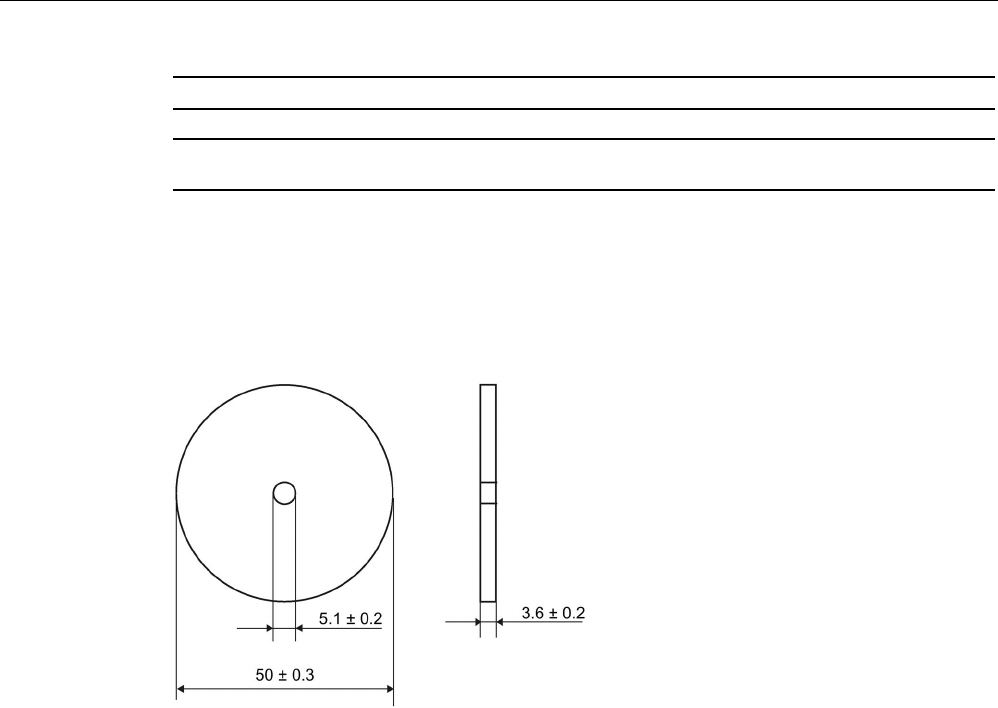
Transponder
7.27 MDS D526
SIMATIC RF200
System Manual, 07/2017, J31069-D0227-U001-A9-7619 319
6GT2600-5AH00
Weight
13 g
Type of mounting 1 x M4 screw 2)
≤ 1 Nm
1)
The values for shock and vibration are maximum values and must not be applied continuously.
2 ) To prevent it loosening during operation, secure the screw with screw locking varnish.
7.27.5
Dimension drawing
Figure 7-77 Dimensional drawing of MDS D526
All dimensions in mm
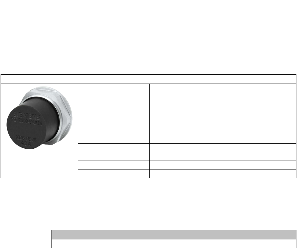
Transponder
7.28 MDS D528
SIMATIC RF200
320 System Manual, 07/2017, J31069-D0227-U001-A9-7619
7.28
MDS D528
7.28.1
Characteristics
MDS D528
Characteristics
Area of application Compact and rugged ISO transponder; suitable for screw
mounting
Use in assembly and production lines in the powertrain
sector
The rugged housing of the MDS D528 means that it can
also be used in extreme environmental conditions without
problems.
Memory size
8192 bytes of FRAM user memory
Write/read range
See section "Field data (Page 39)"
Mounting on metal
Yes
ISO standard
ISO 15693
Degree of protection
IP68/IPx9K
7.28.2
Ordering data
Table 7- 69 Ordering data for MDS D528
Article number
MDS D528
6GT2600-5AK00

Transponder
7.28 MDS D528
SIMATIC RF200
System Manual, 07/2017, J31069-D0227-U001-A9-7619 321
7.28.3
Application example
Figure 7-78 Application example
7.28.4
Technical specifications
Table 7- 70 Technical specifications for MDS D528
6GT2600-5AK00
Product type designation SIMATIC MDS D528
Memory
Memory configuration
• UID • 8 bytes
• User memory • 8192 bytes FRAM
• OTP • 32 bytes
Read cycles (at < 40 ℃) > 1012
Write cycles (at < 40 ℃)
> 10
12
Data retention time (at < 40 ℃)
> 10 years
Write/read distance (Sg) Dependent on the reader used, see section "Field
data (Page 39)"
MTBF (Mean Time Between Failures)
228 years

Transponder
7.28 MDS D528
SIMATIC RF200
322 System Manual, 07/2017, J31069-D0227-U001-A9-7619
6GT2600-5AK00
Mechanical specifications
Housing
• Material • Plastic PA 6.6 GF
• Color • Black
Recommended distance to metal
≥ 0 mm
Power supply
Inductive, without battery
Permitted ambient conditions
Ambient temperature
• during write/read access • -25 to +85 ℃
• outside the read/write field • -40 to +125 ℃
• during storage • -40 to +125 ℃
Degree of protection to EN 60529 • IP68
2 hours, 2 bar, +20 °C
• IPx9K
steam jet: 150 mm; 10 to 15 l/min; 100 bar; 75
°C
Shock according to IEC 68-2-27
1)
500 m/s
2
Vibration according to IEC 68-2-6
1)
200 m/s
2
Torsion and bending load
Not permitted
Design, dimensions and weight
Dimensions (Ø x H)
24 x 20 mm (without set screw)
Weight
35 g
Type of mounting 1x transponder set screw M8
SW 22; ≤ 8 Nm
1) The values for shock and vibration are maximum values and must not be applied continuously.
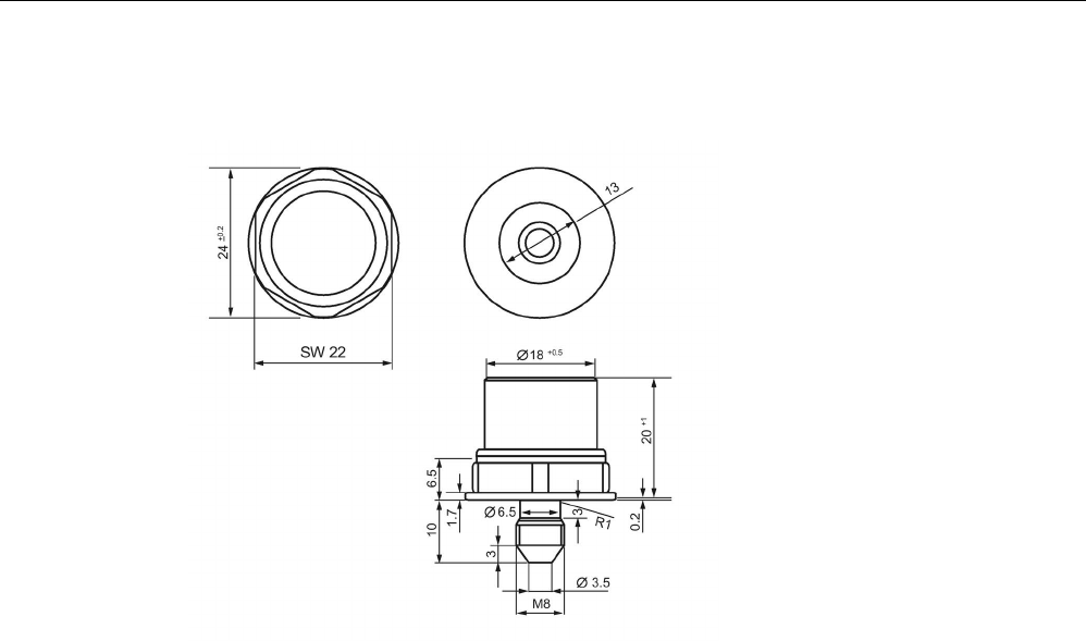
Transponder
7.28 MDS D528
SIMATIC RF200
System Manual, 07/2017, J31069-D0227-U001-A9-7619 323
7.28.5
Dimension drawing
Figure 7-79 Dimensional drawing of MDS D528
All dimensions in mm