Siemens RF290R RF-Long-Range Reader with external Antenna User Manual SIMATIC RF200
Siemens AG RF-Long-Range Reader with external Antenna SIMATIC RF200
UserManual.wiki
>
Siemens
>
RF290R User Manual
User Manual
Navigation menu
Upload a User Manual
Namespaces
Wiki Guide
HTML
PDF
Info
Views
User Manual
Discussion / Help
Navigation
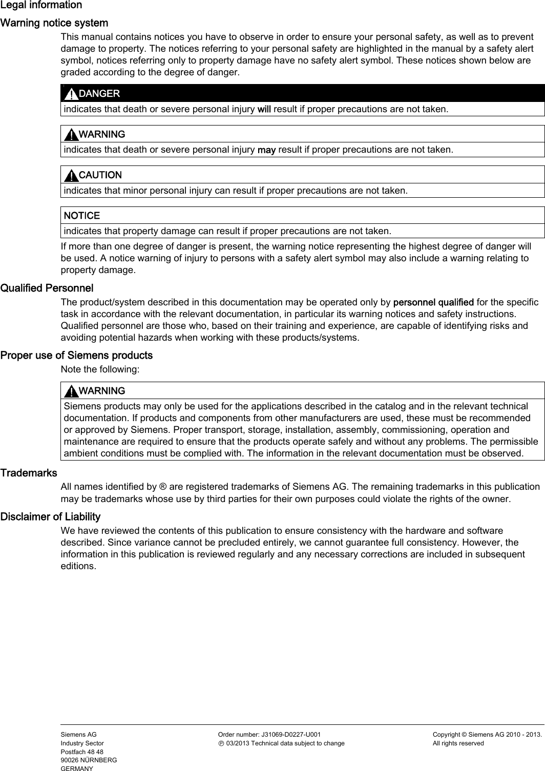
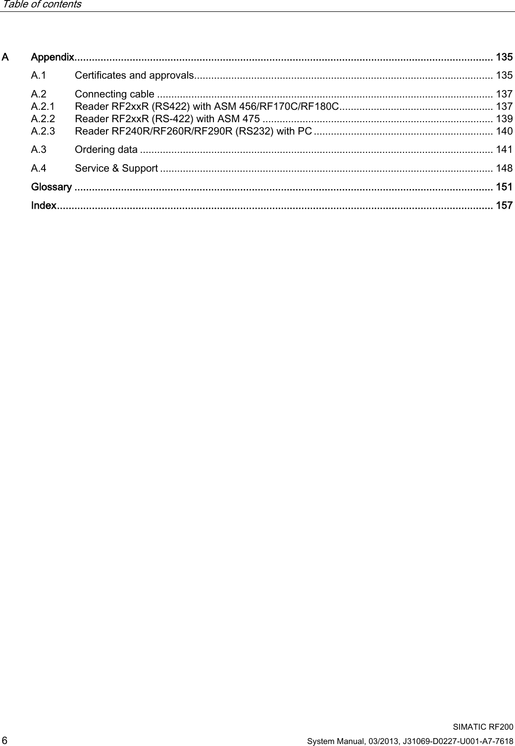


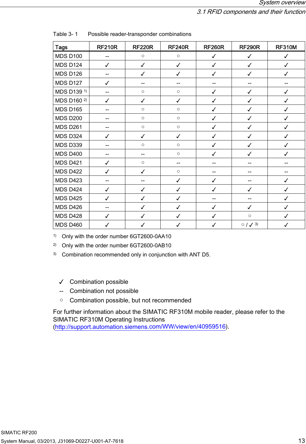
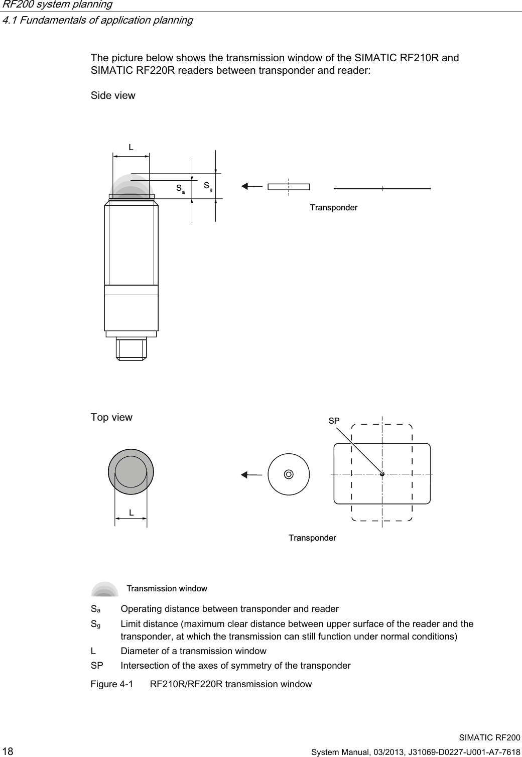
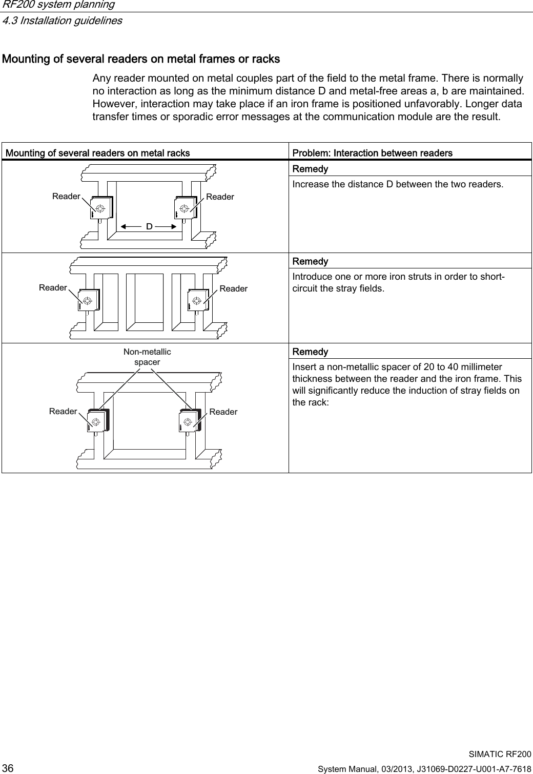
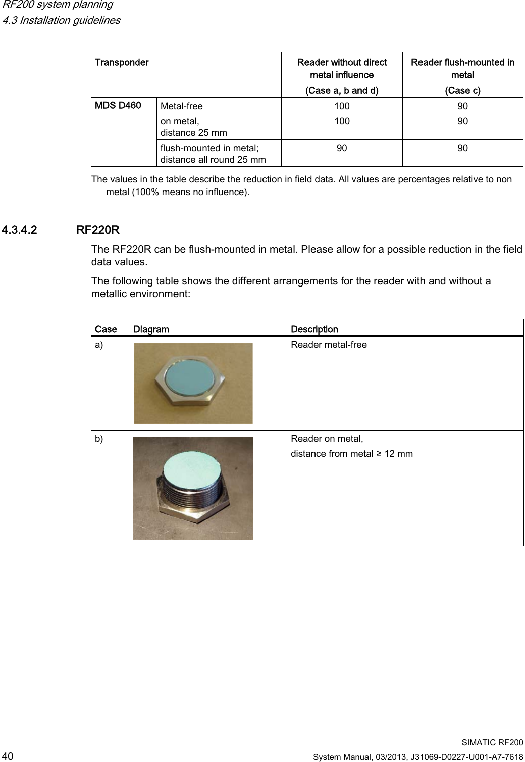
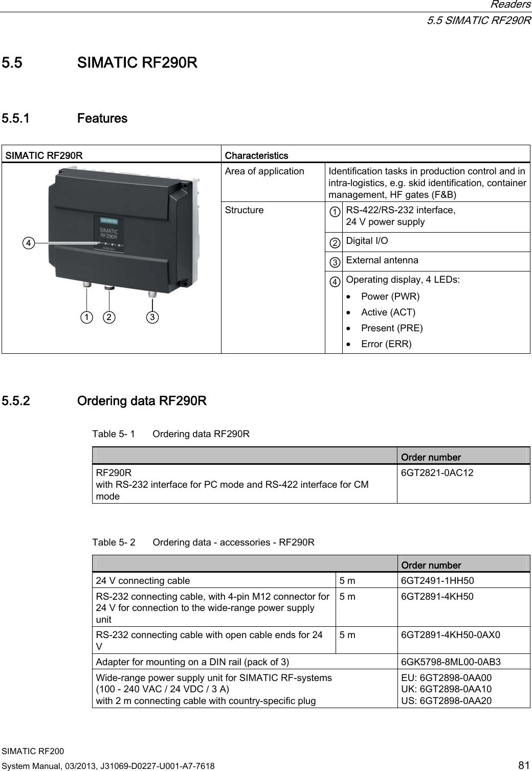
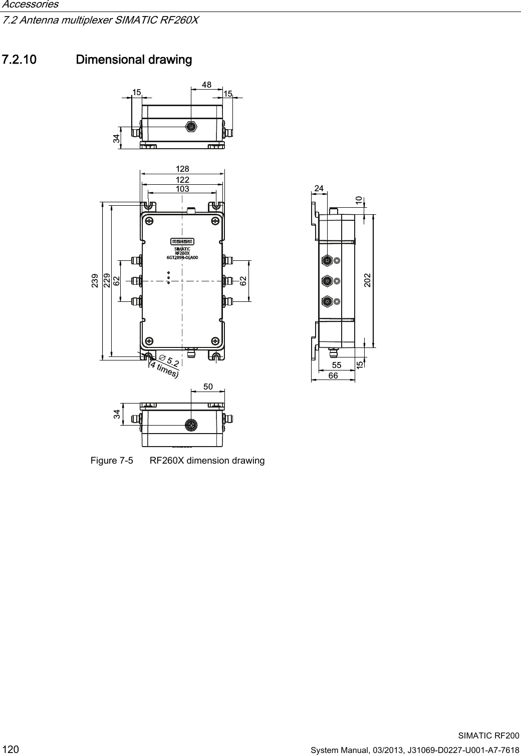
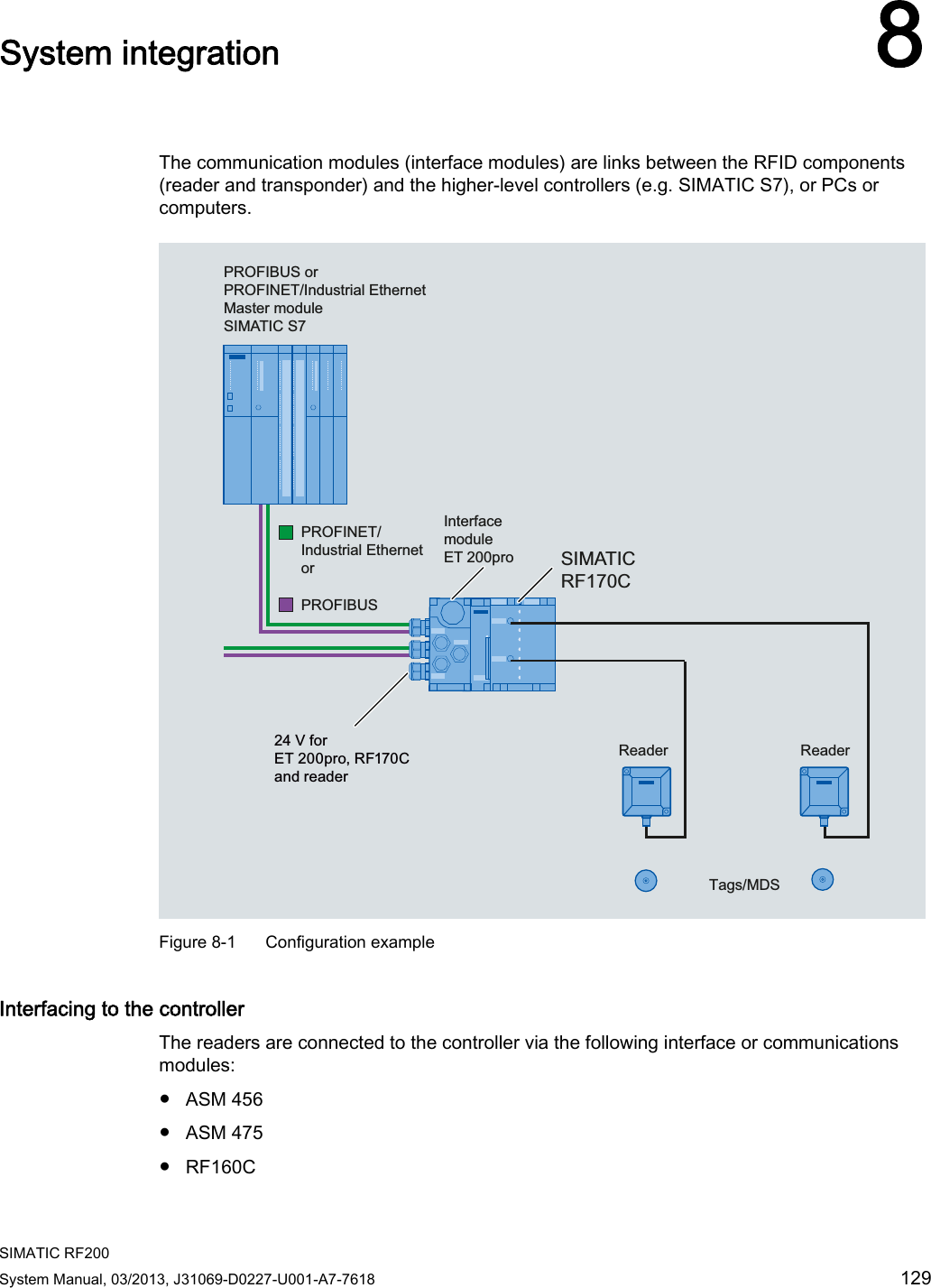
![System overview 3.1 RFID components and their function SIMATIC RF200 12 System Manual, 03/2013, J31069-D0227-U001-A7-7618 3.1 RFID components and their function RF200 system components 5HDGHUV &RPPXQLFDWLRQVPRGXOHV3RZHUDQGGDWDWUDQVPLVVLRQ0+],626HULDODV\QFKURQRXVLQWHUIDFH56DQG56RQO\ZLWK5)55)55)53&LQWHUIDFHWKLUGSDUW\3/&$60IRU6,0$7,&65)&IRU(7SUR$60bIRU352),%86'3'395)&5)&IRU352),1(7,27&3,37UDQVSRQGHUV5)&IRU352),%86'3'3ತ90'6'0'6' 0'6'0'6'0'6'0'6'0'6'0'6'0'6'0'6'0'6' 0'6'0'6' 0'6'0'6'5)55)5 5)55)0 5)5 5)50'6'0'6'0'6'0'6'0'6' Figure 3-1 RF200 system overview](https://usermanual.wiki/Siemens/RF290R/User-Guide-1938433-Page-14.png)
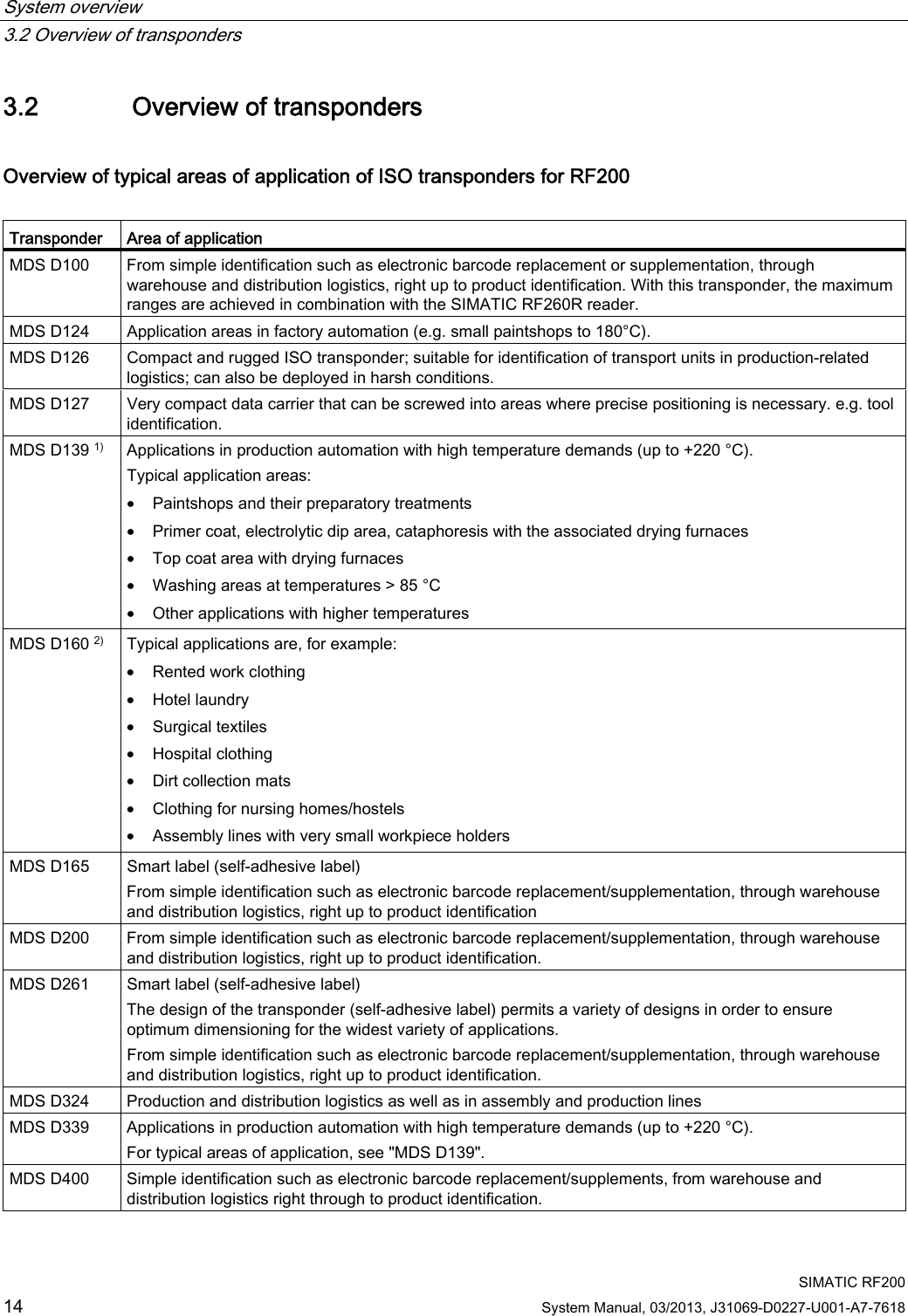

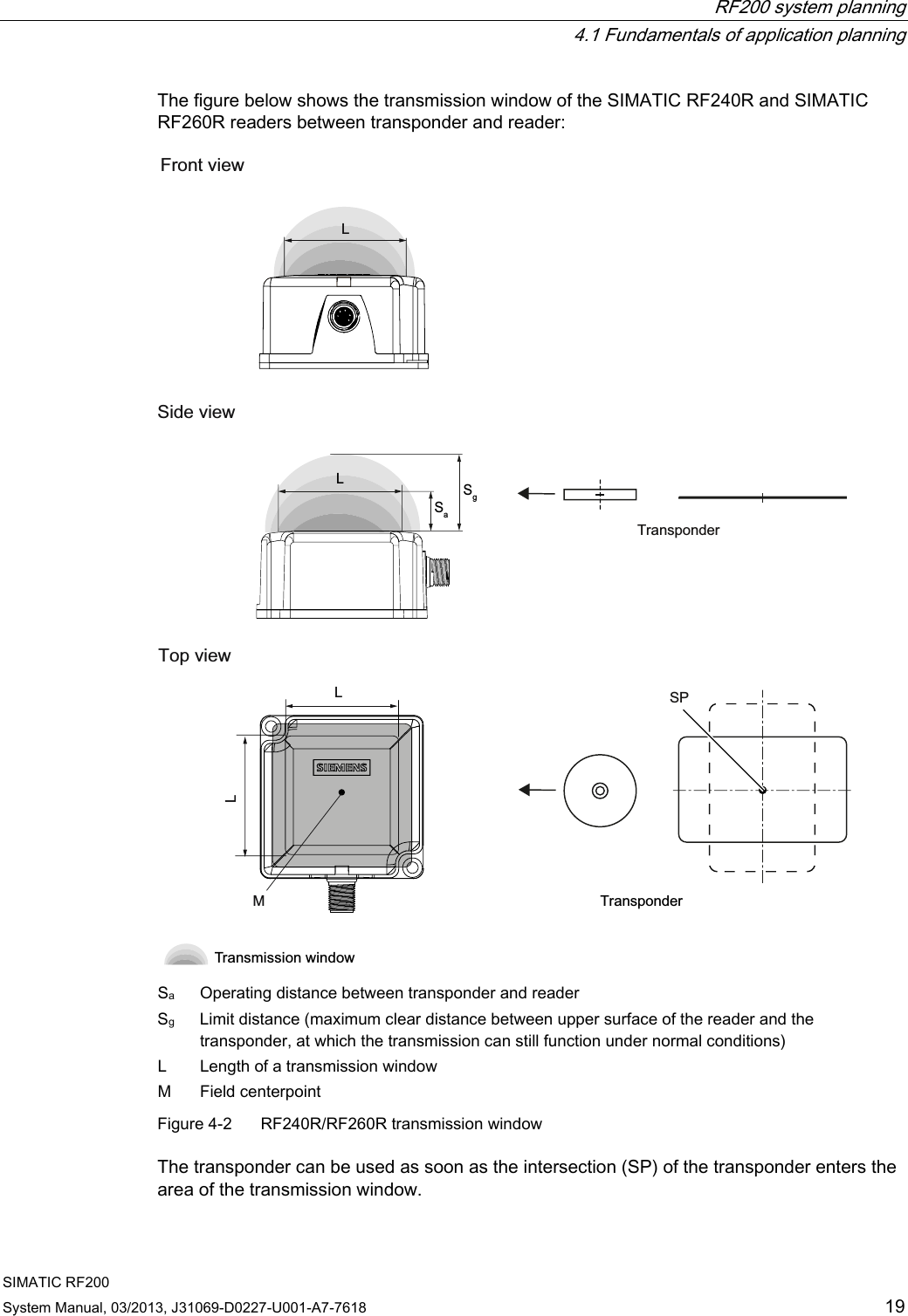
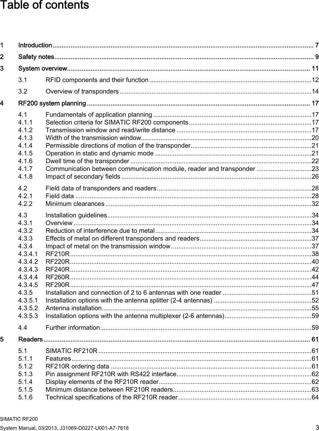
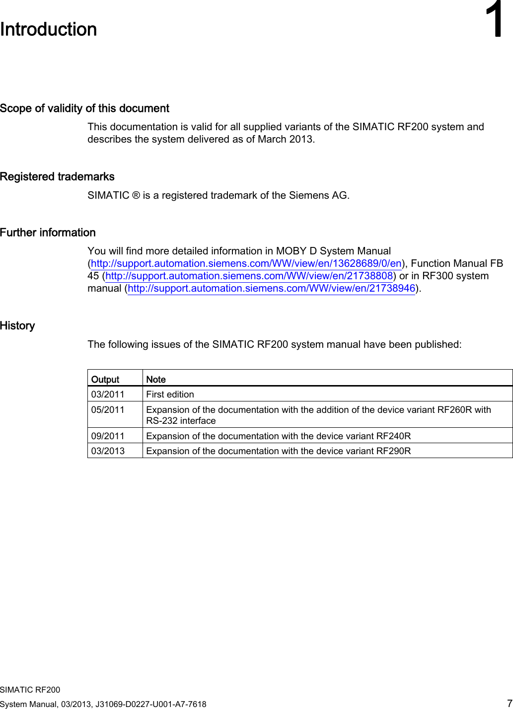
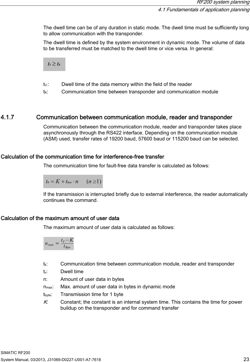
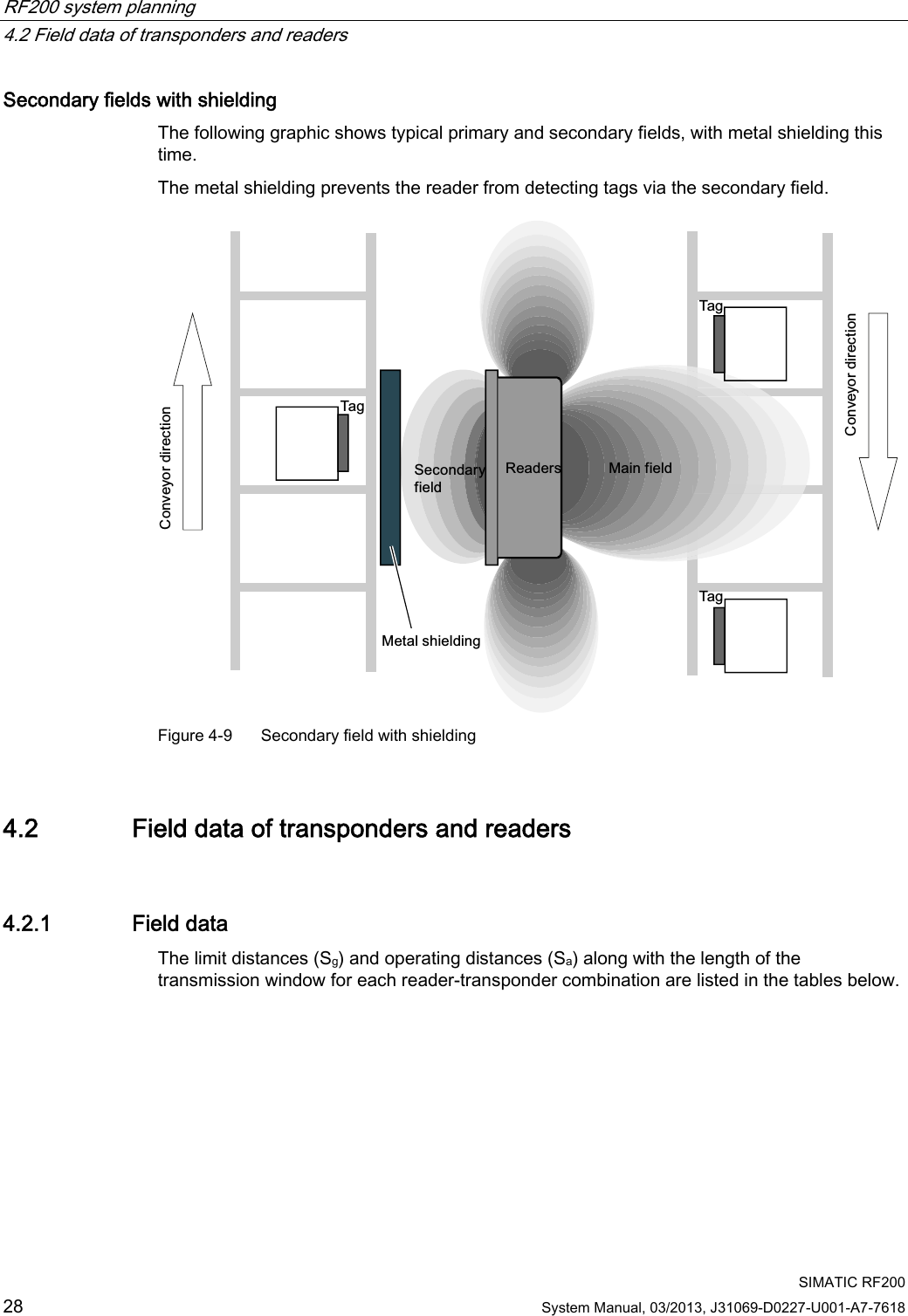
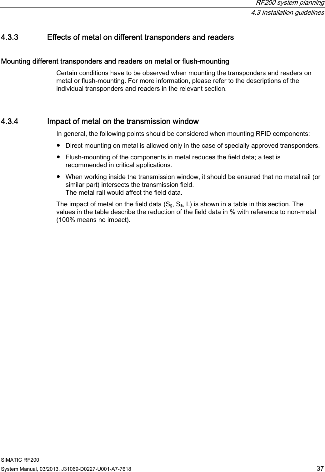
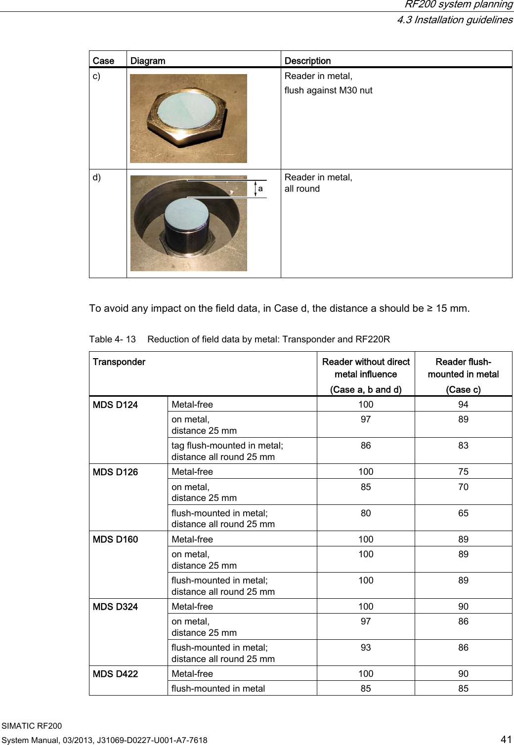
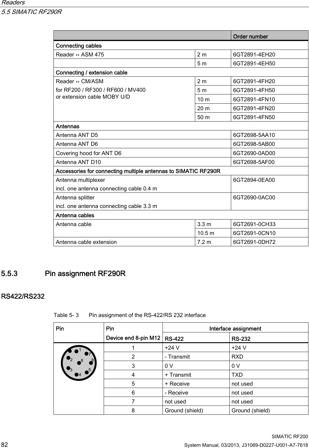
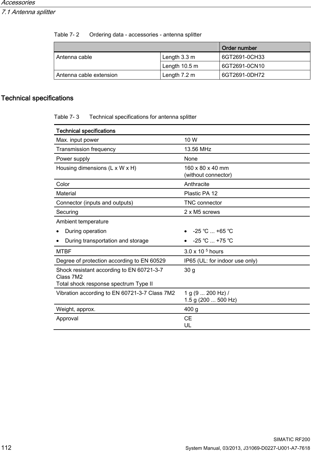
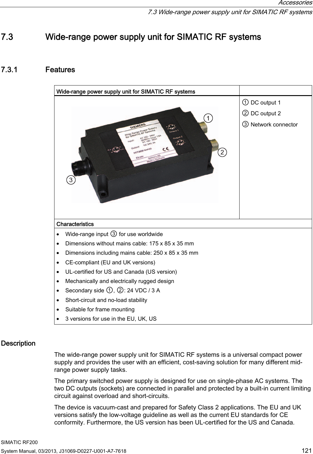
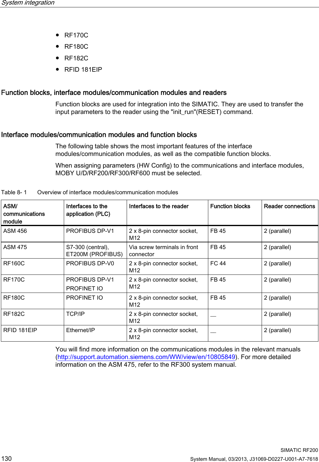
![RF200 system planning 4.1 Fundamentals of application planning SIMATIC RF200 22 System Manual, 03/2013, J31069-D0227-U001-A7-7618 Note Note that in a metallic environment the values for the limit distance are reduced. Operation in dynamic mode When working in dynamic mode, the transponder moves past the reader. The transponder can be used as soon as the intersection (SP) of the transponder enters the circle of the transmission window. In dynamic mode, the operating distance (Sa) is of primary importance. [Operating distances, see Chapter Field data of transponders and readers (Page 28)] 7UDQVPLVVLRQZLQGRZ7UDQVSRQGHU7UDQVSRQGHU3ODQYLHZ6363 Figure 4-5 Operation in dynamic mode 4.1.6 Dwell time of the transponder The dwell time is the time in which the transponder remains within the transmission window of a reader. The reader can exchange data with the transponder during this time. The dwell time is calculated thus: 0,8 [ ][/]TagvL mtv m s⋅= tV: Dwell time of the transponder L: Length of the transmission window vTag: Speed of the transponder (tag) in dynamic mode 0,8: Constant factor used to compensate for temperature impacts and production tolerances](https://usermanual.wiki/Siemens/RF290R/User-Guide-1938433-Page-24.png)
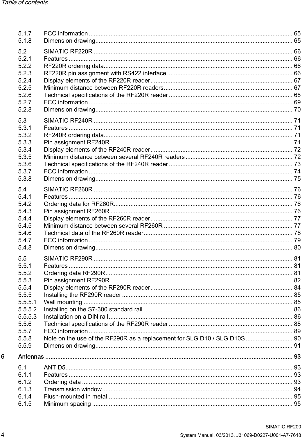
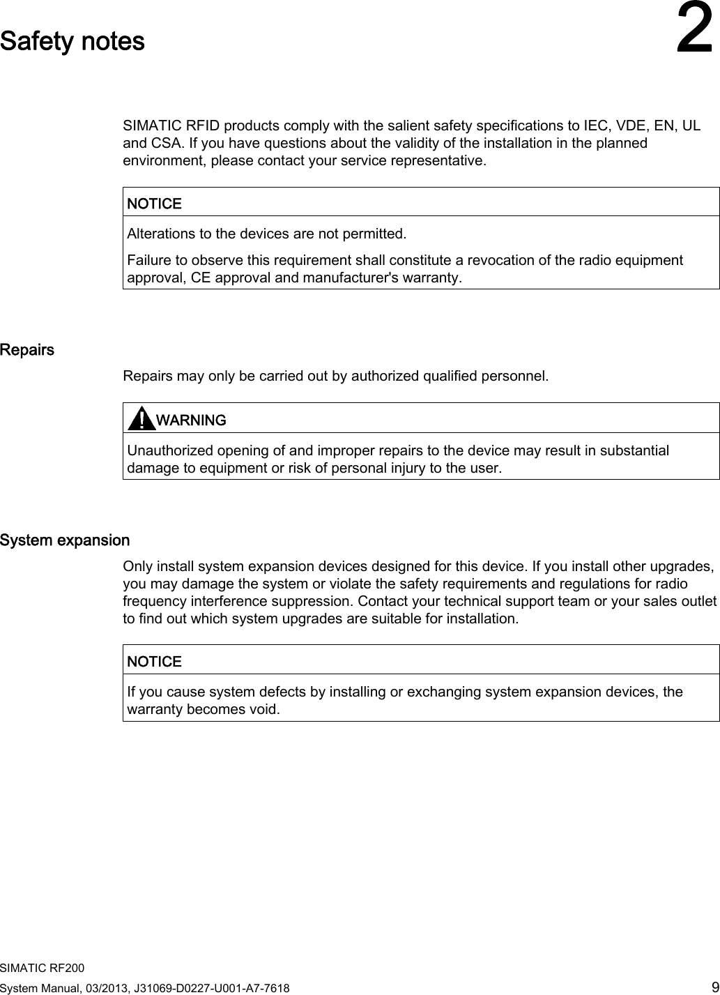
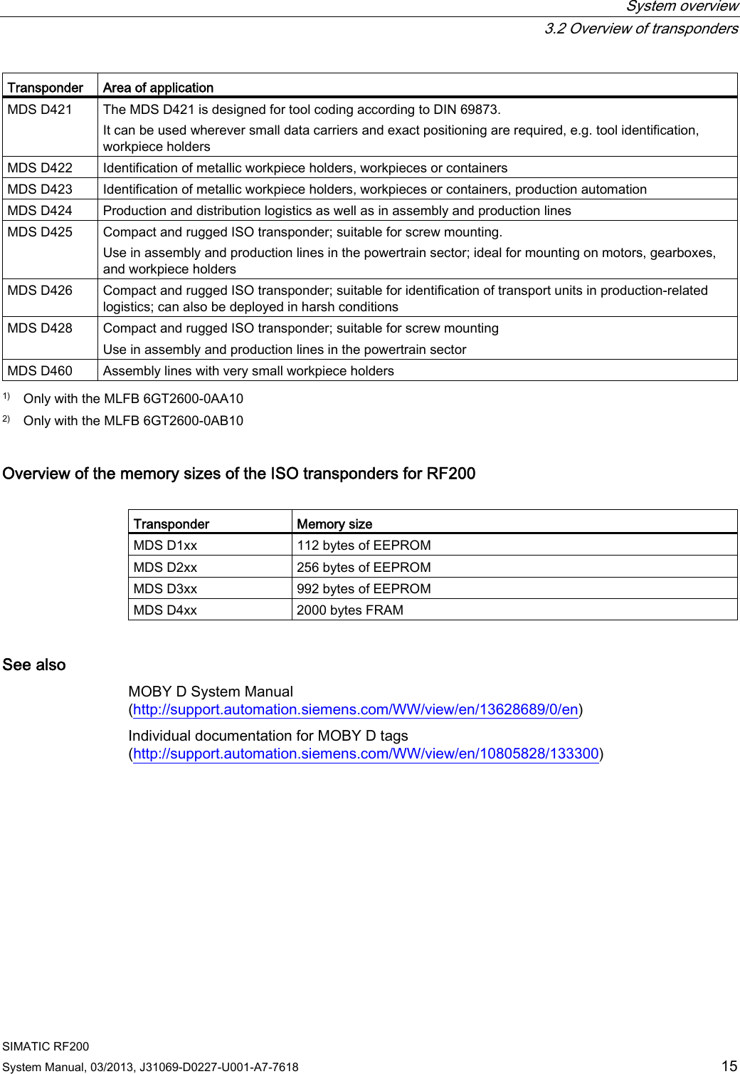
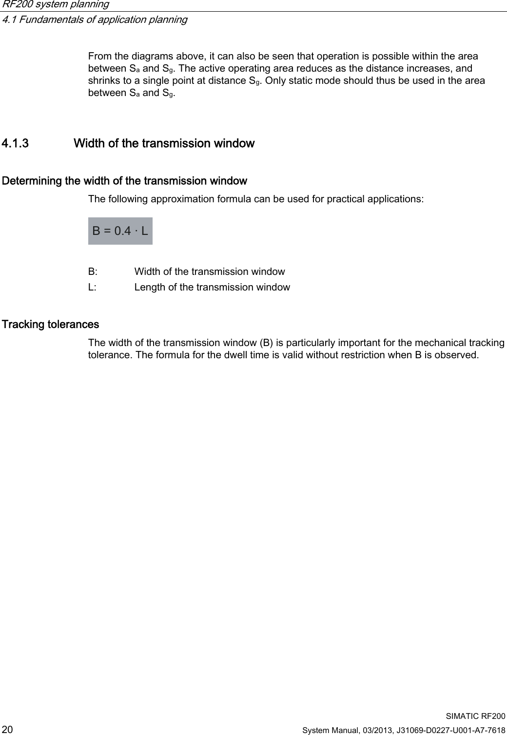
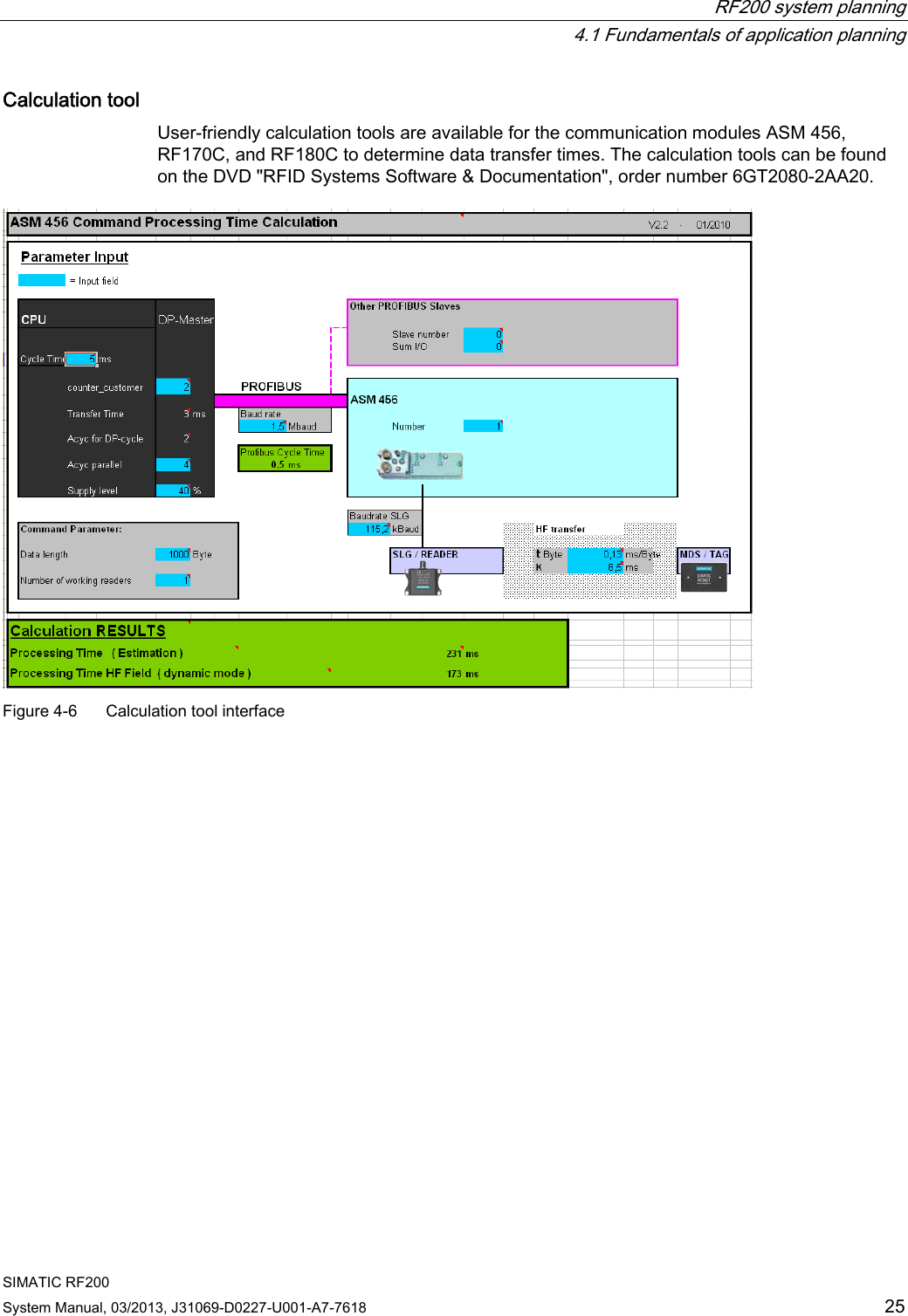
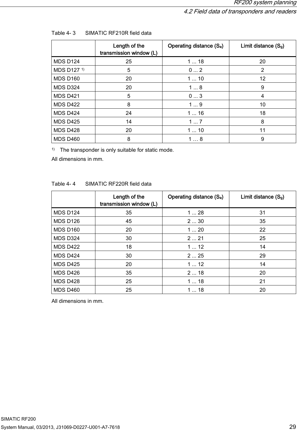
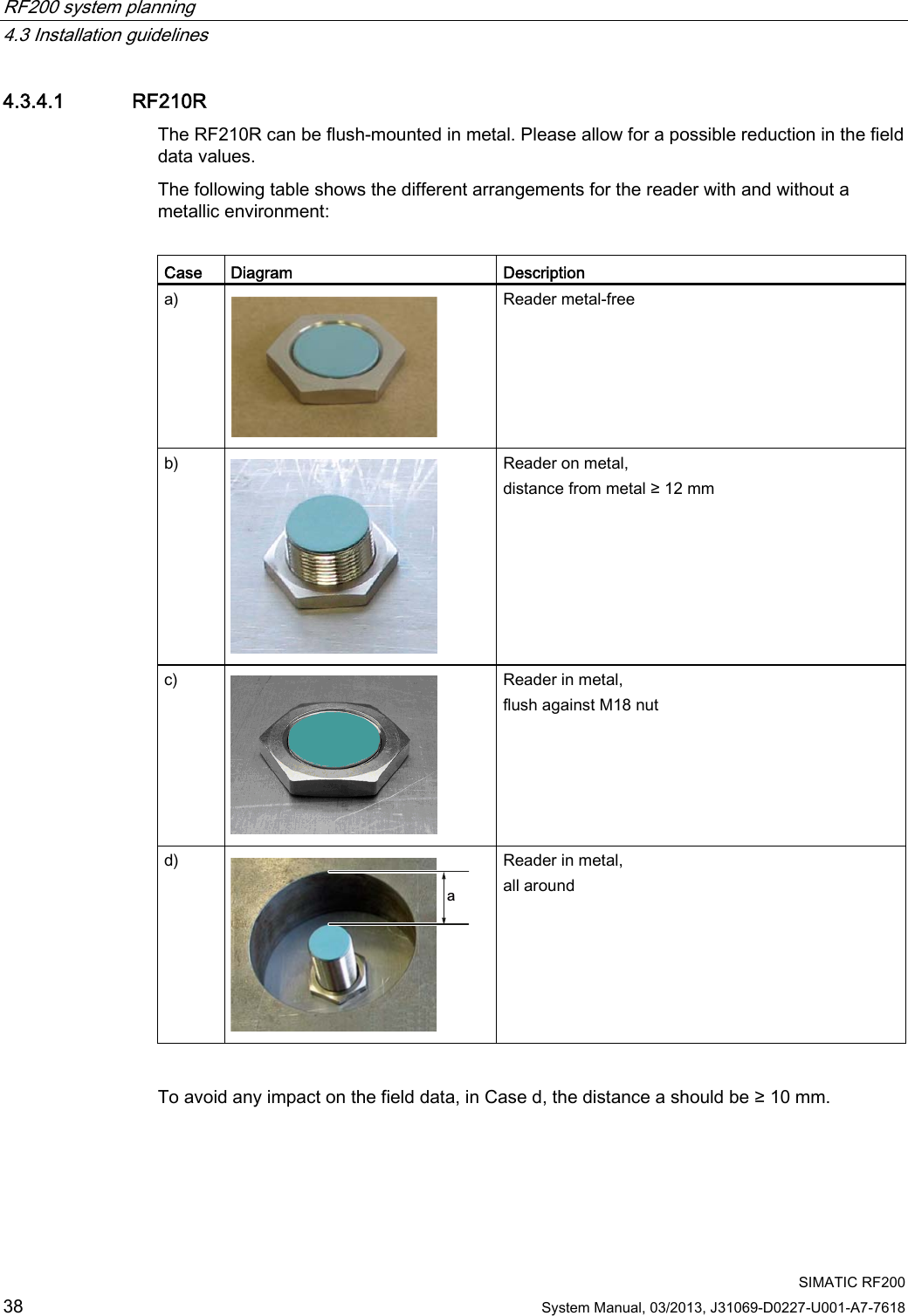
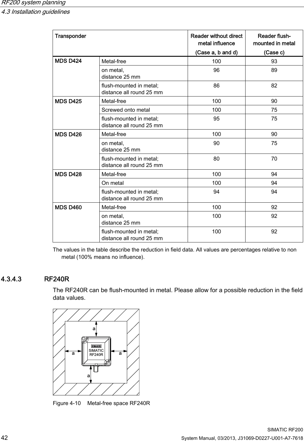
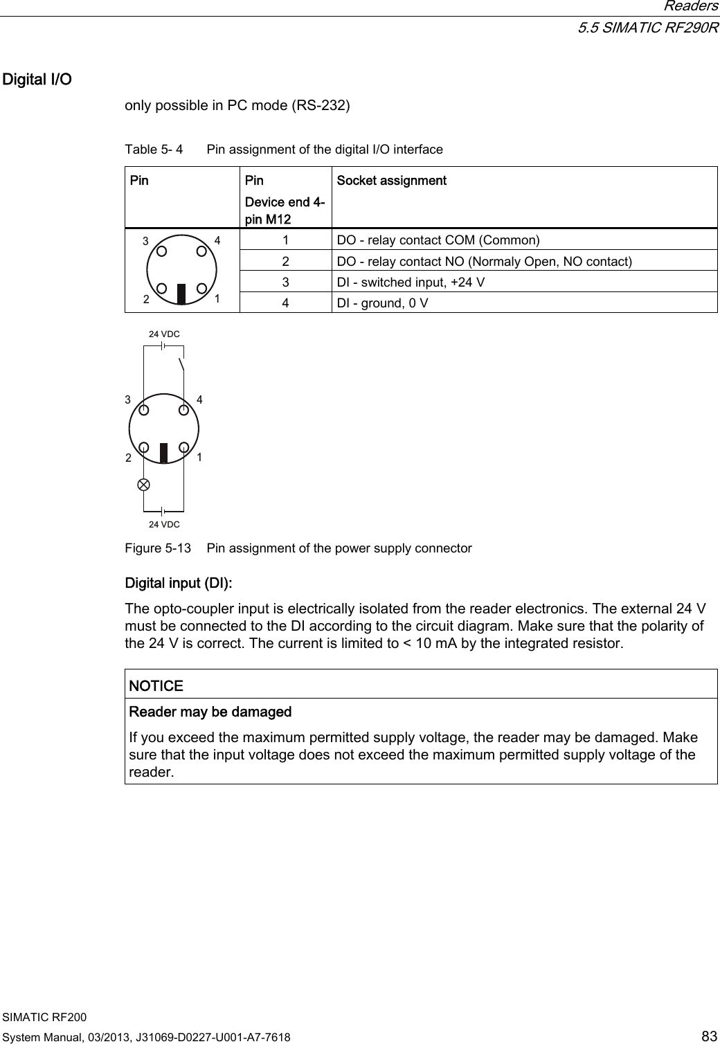
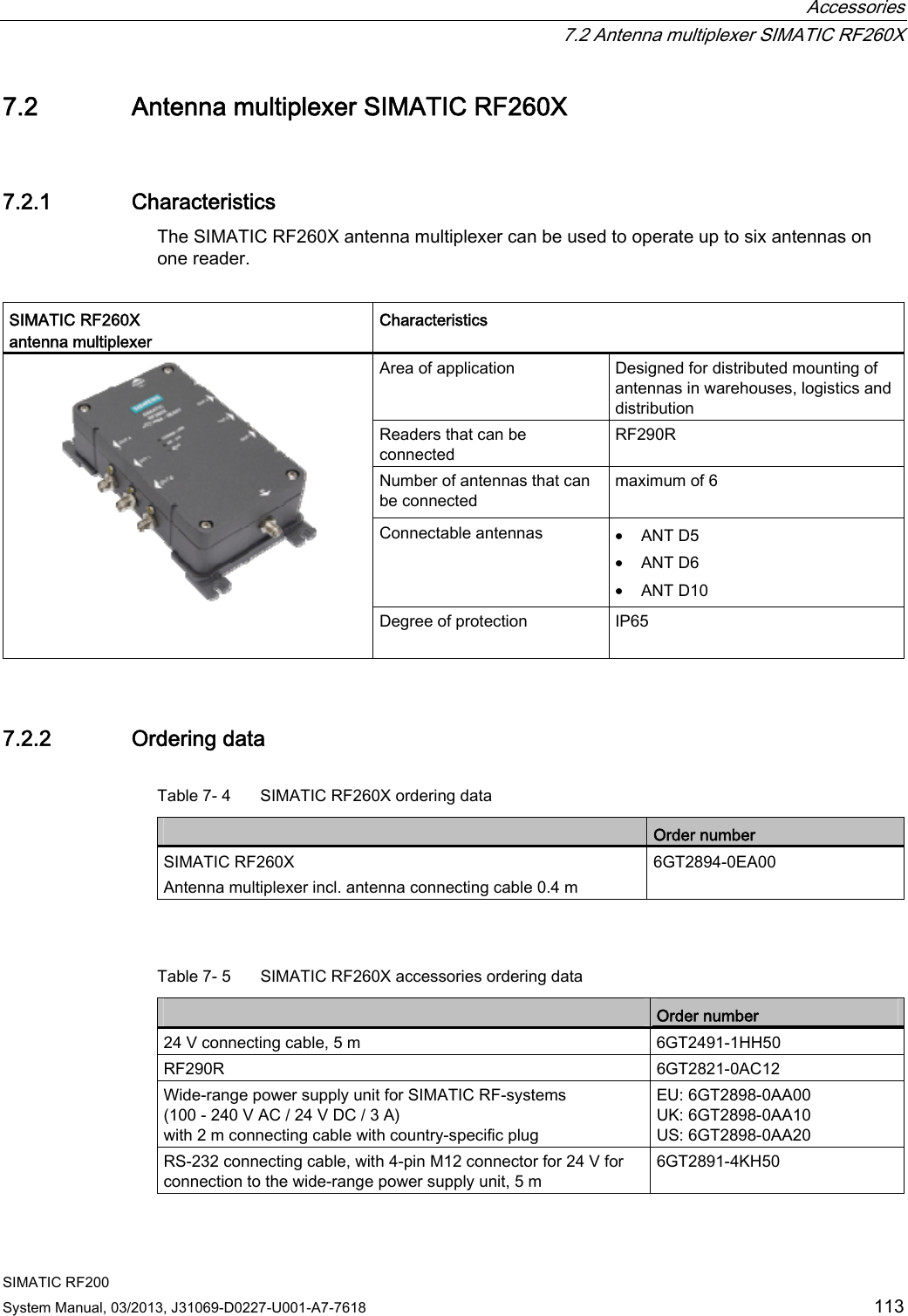
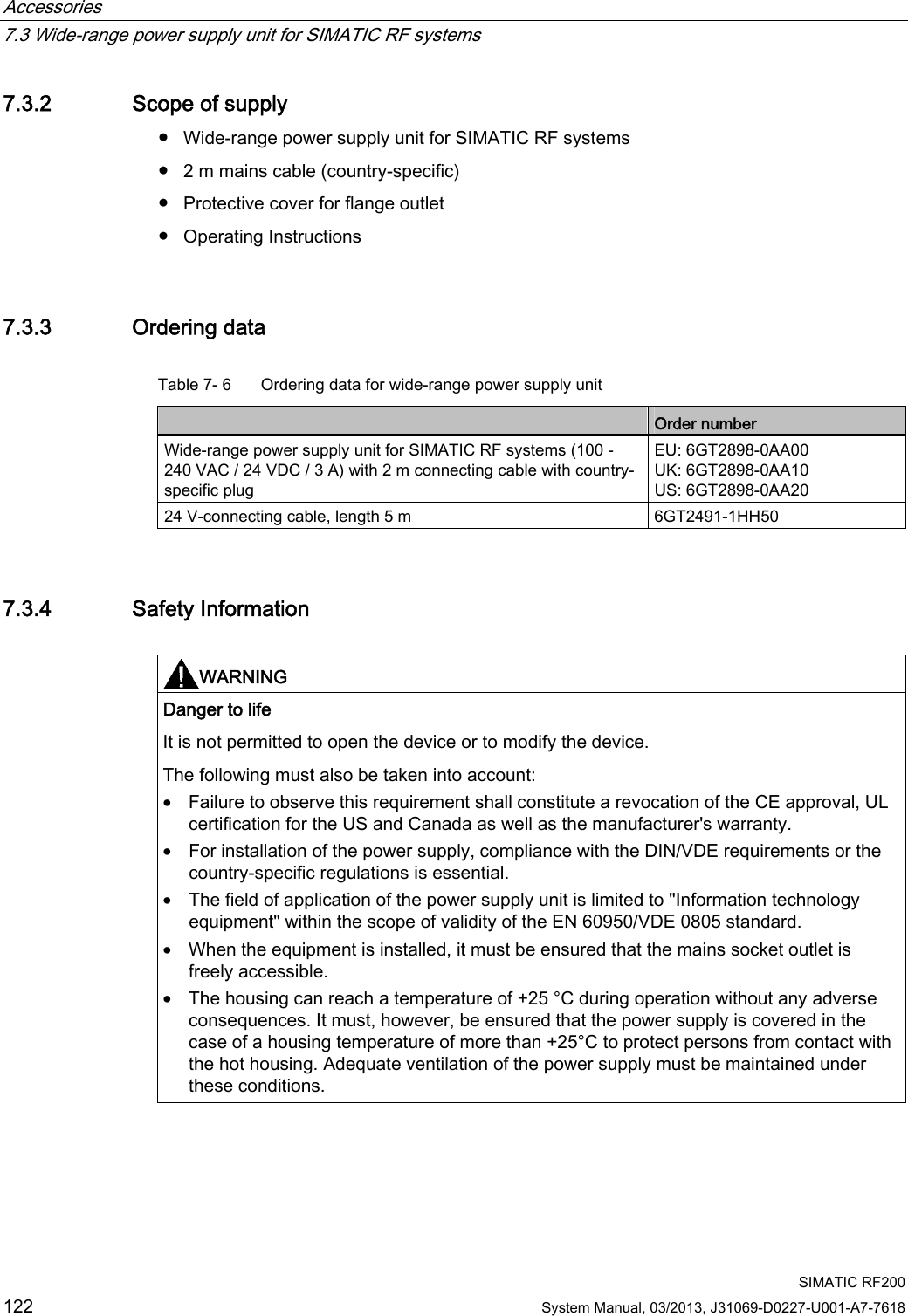
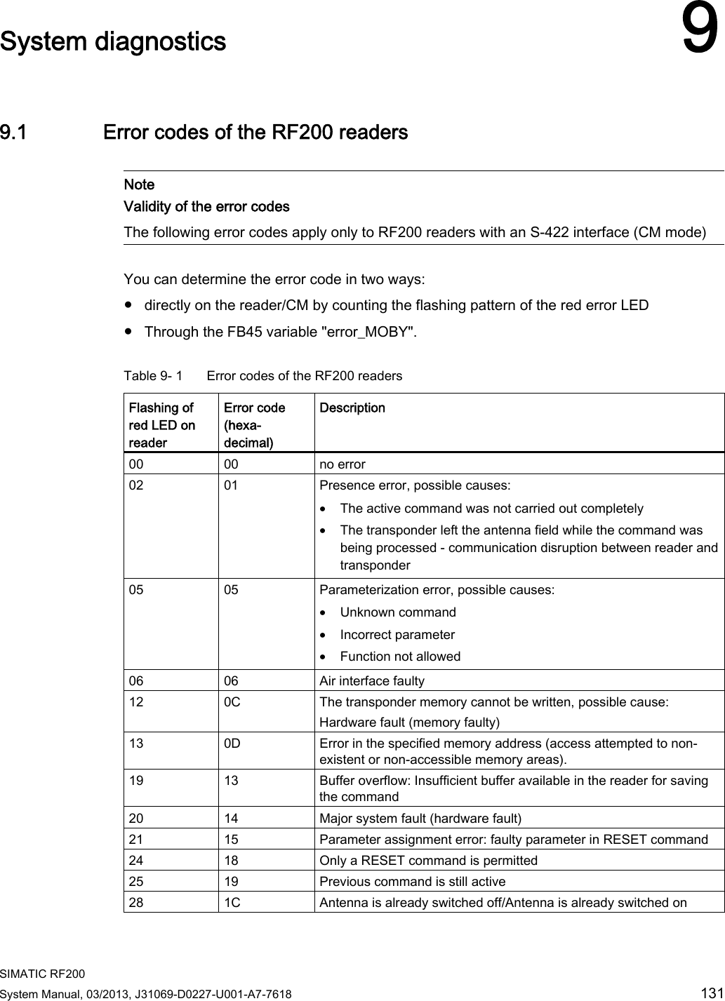
![RF200 system planning 4.1 Fundamentals of application planning SIMATIC RF200 24 System Manual, 03/2013, J31069-D0227-U001-A7-7618 Time constants K and tbyte Table 4- 1 Typical communication time on the serial interface when operating with presence check Read Write All MDS MDS D1xx/D3xx MDS D2xx MDS D4xx Transfer rate [baud] K [ms] tbyte [ms] K [ms] tbyte [ms] K [ms] tbyte [ms] K [ms] tbyte [ms] 19200 35 1.08 41 2.66 50 8.1 35 1.08 57600 34 0.59 28 2.28 33 7.7 34 0.59 115200 26 0.56 26 2.17 31 7.6 26 0.56 Table 4- 2 Typical command duration on the air interface for operation without presence check TAG type Command K [ms] Tbyte [ms] All MDS Read 20 0.55 EEPROM (MDS D1xx/D3xx) Write 27 2.2 EEPROM (MDS D2xx) Write 19 7.5 FRAM (MDS D4xx) Write 27 0.55 In dynamic mode, the values for K and tbyte are independent of the transmission speed. The communication time only includes the processing time between the reader and the transponder and the internal system processing time of these components. The communication times between the communication module and the reader do not have to be taken into account because the command for reading or writing is already active when the transponder enters the transmission field of the reader. The values shown above must be used when calculating the maximum quantity of user data in dynamic mode. They are applicable for both writing and reading.](https://usermanual.wiki/Siemens/RF290R/User-Guide-1938433-Page-26.png)
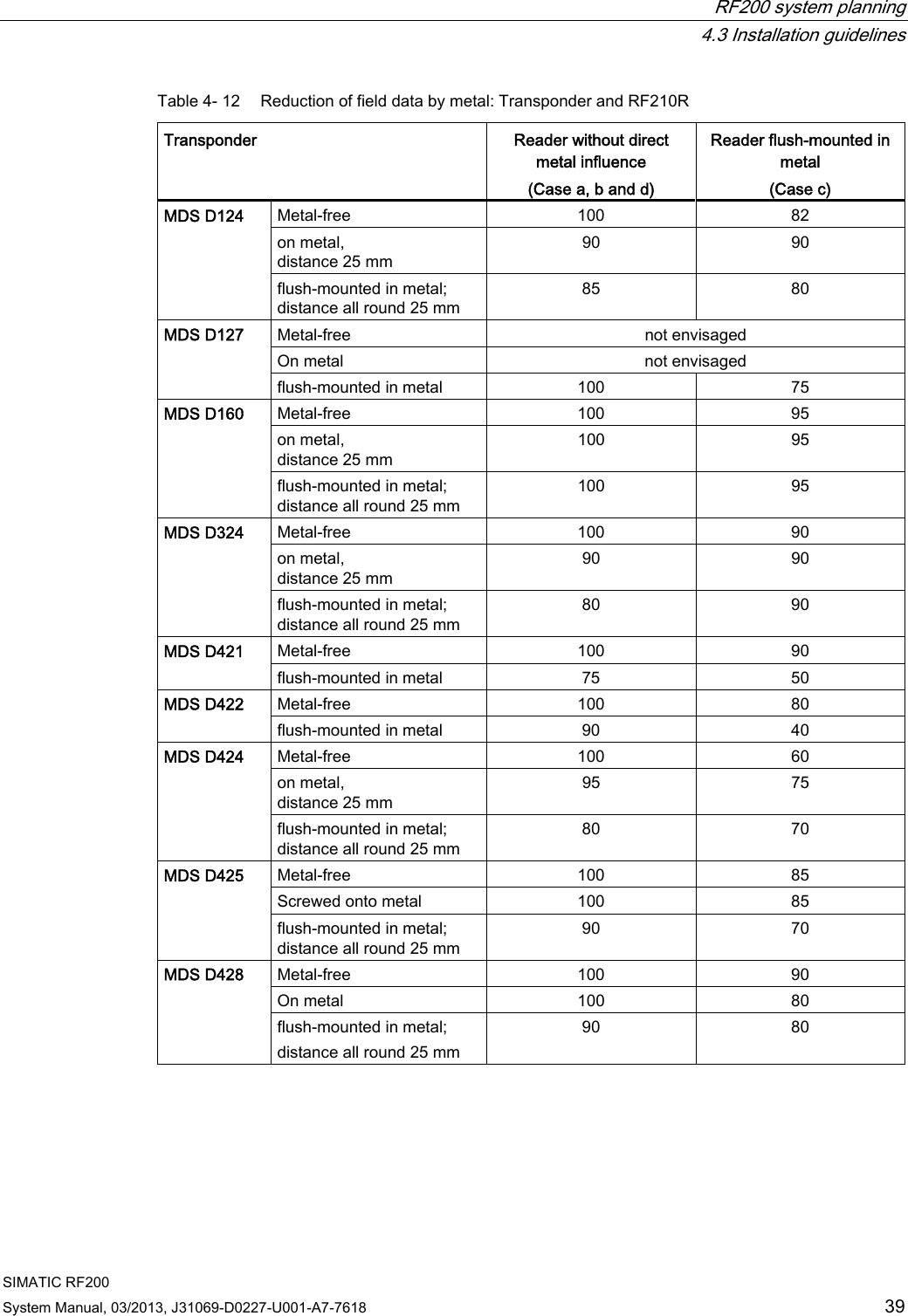
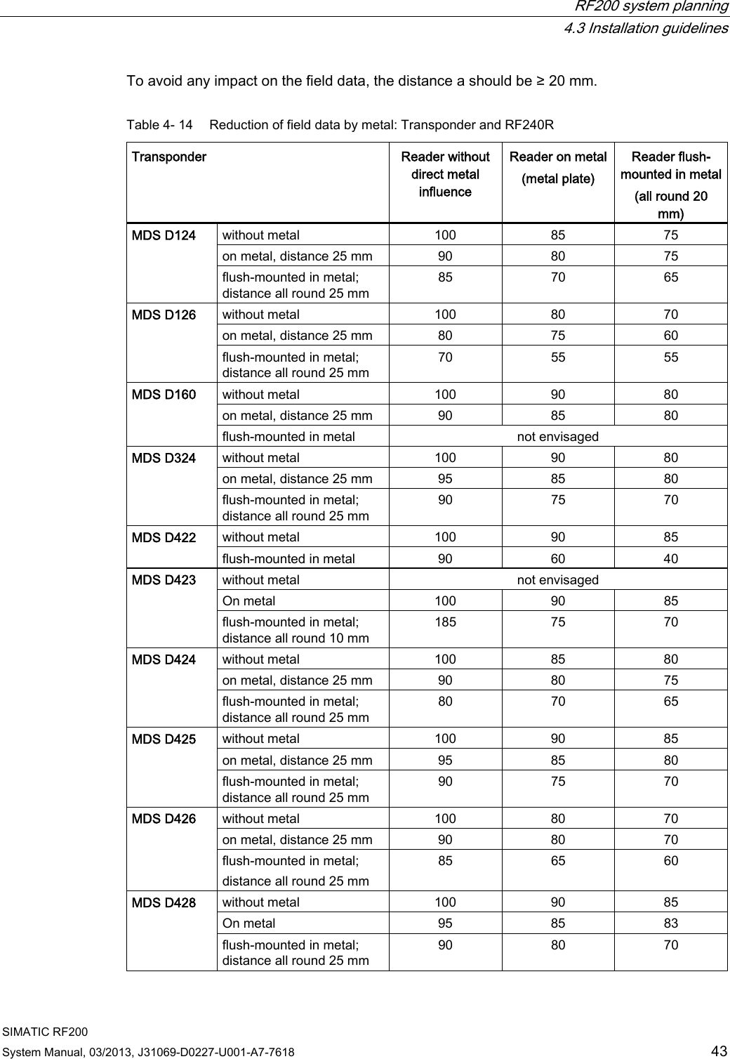

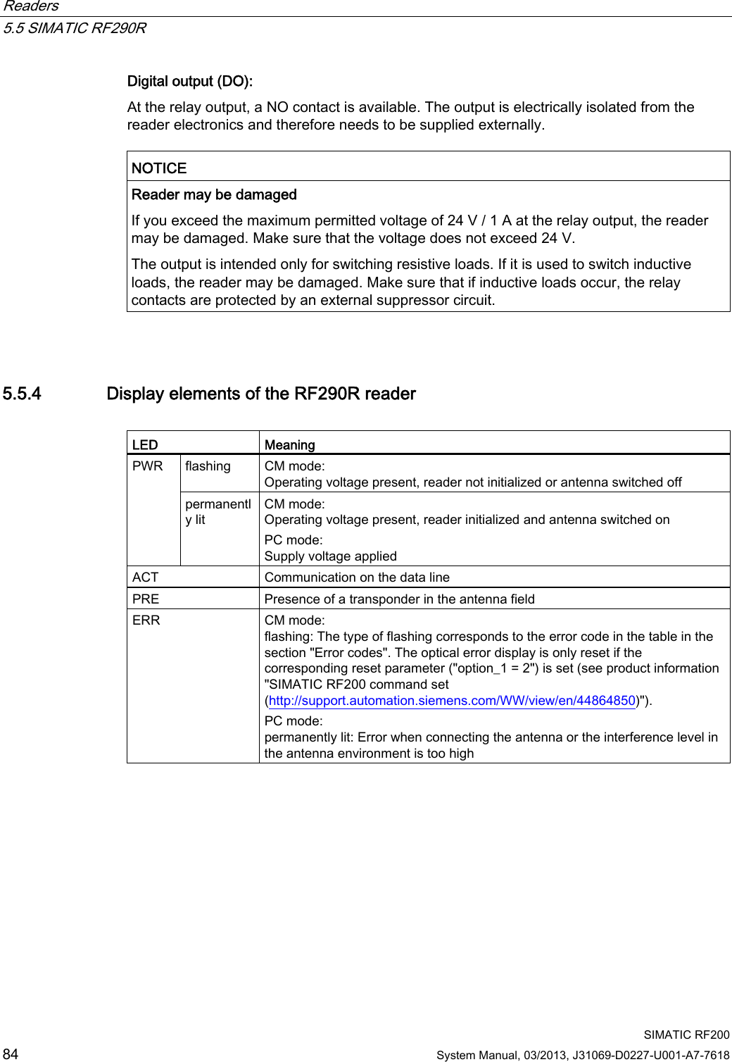


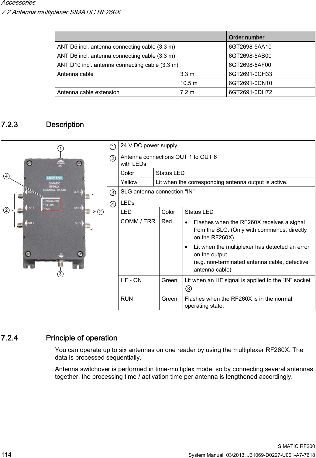

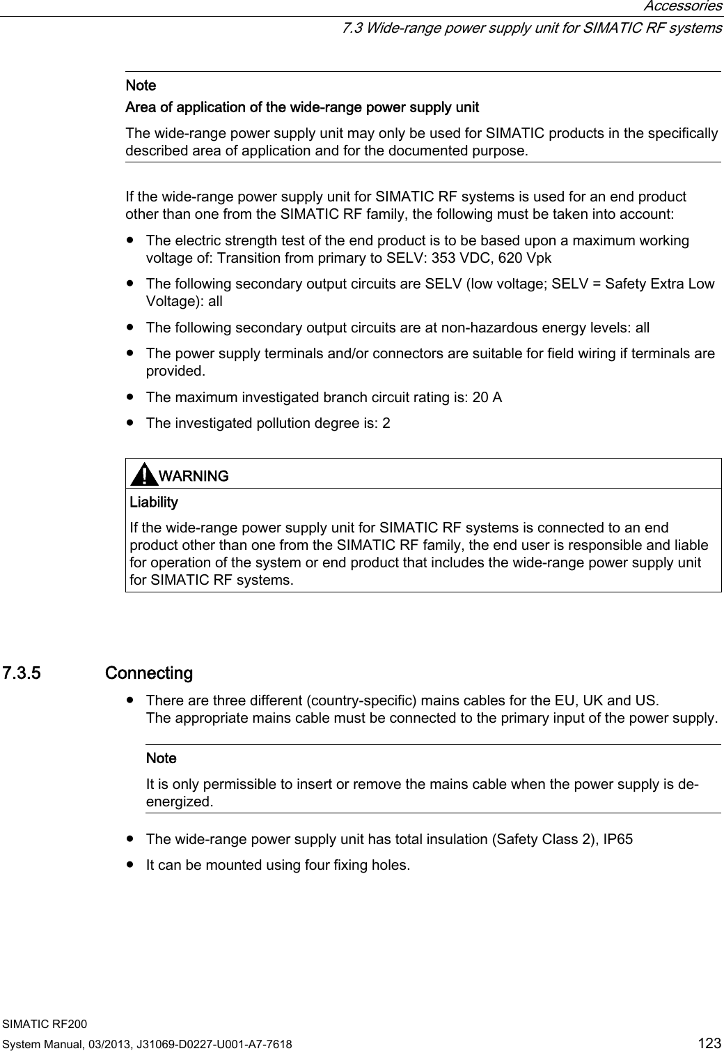

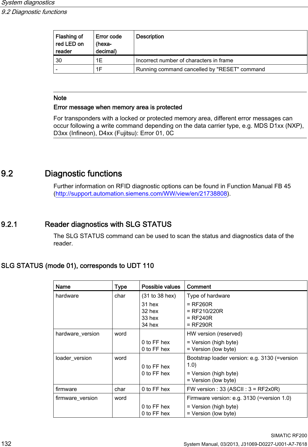

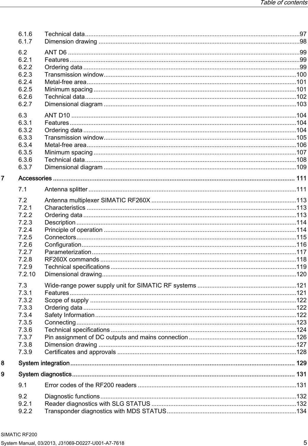
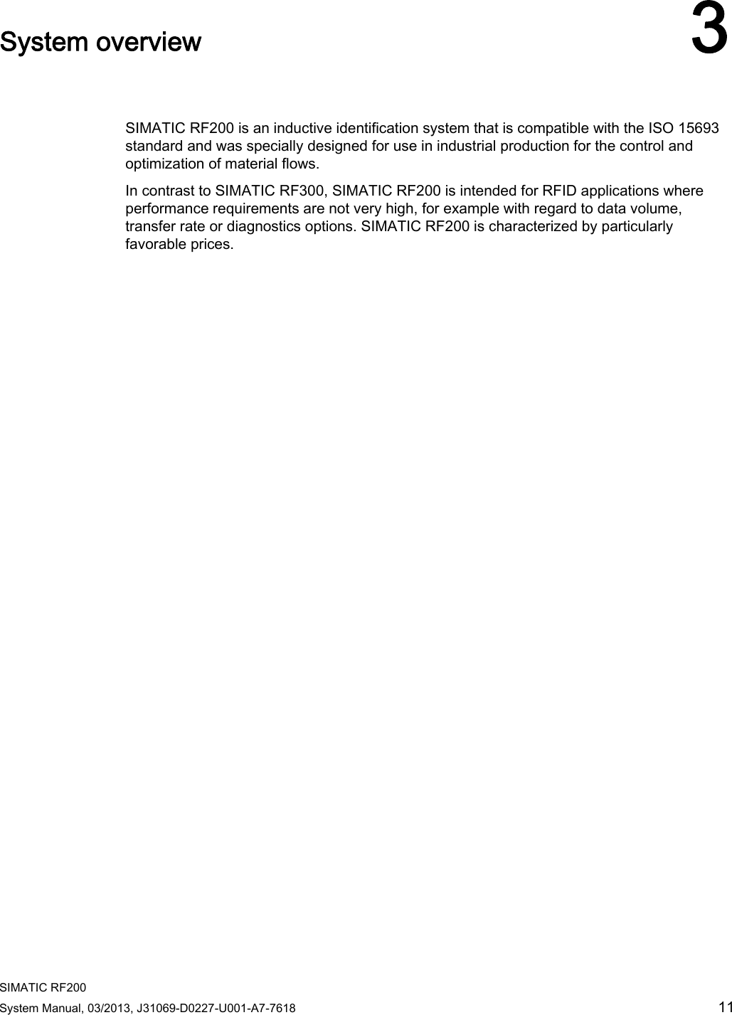
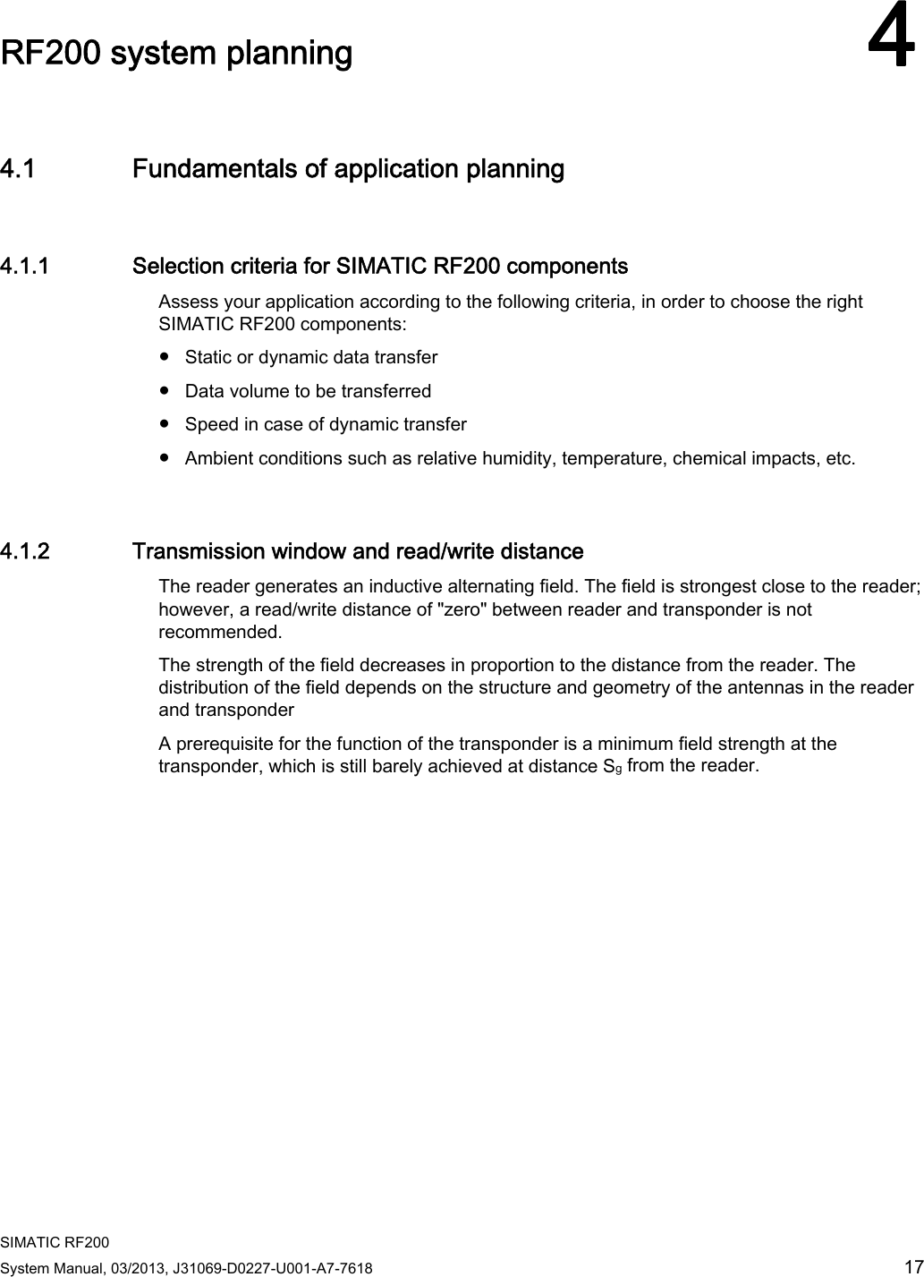
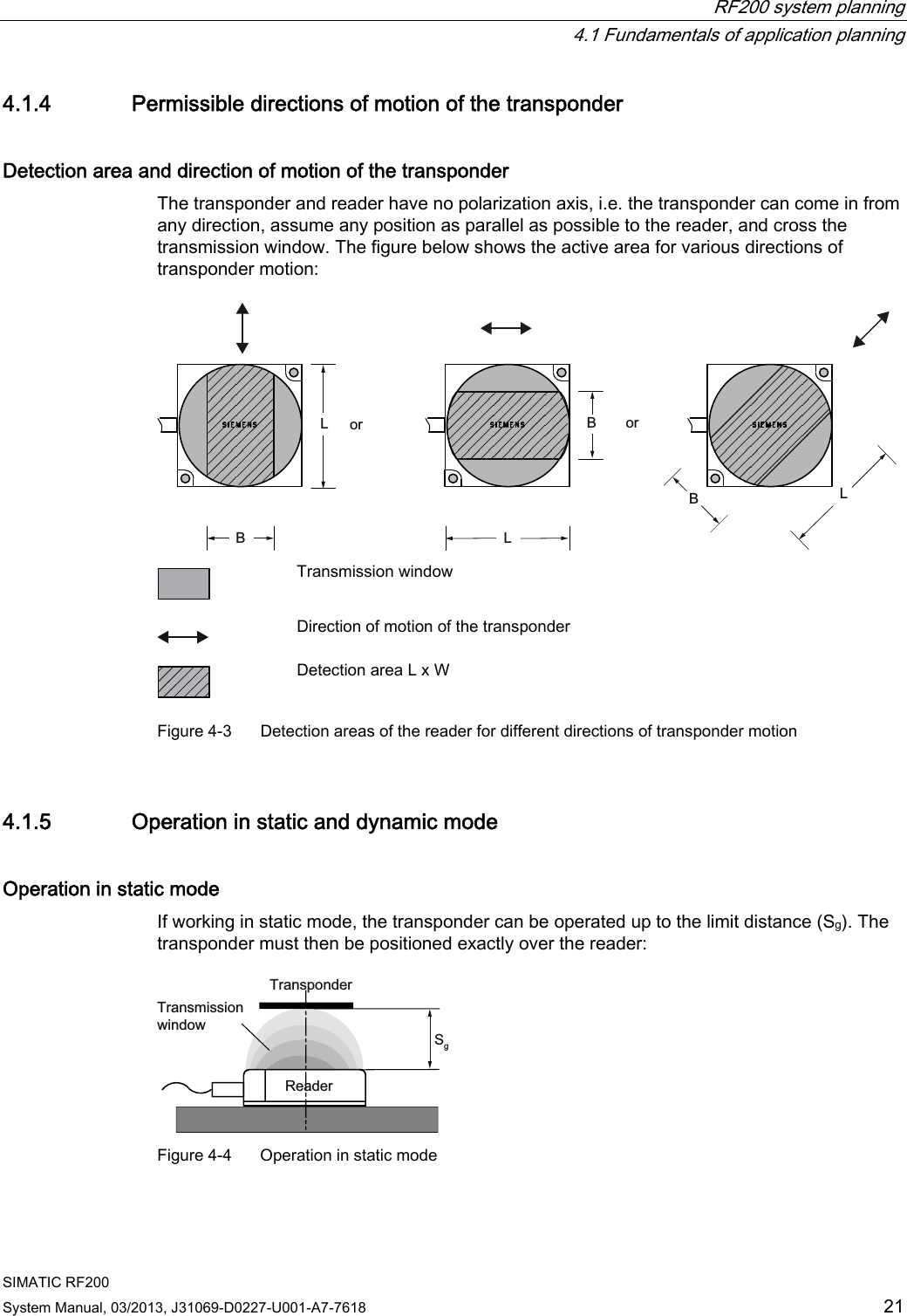
![System diagnostics 9.2 Diagnostic functions SIMATIC RF200 134 System Manual, 03/2013, J31069-D0227-U001-A7-7618 9.2.2 Transponder diagnostics with MDS STATUS The MDS STATUS command can be used to scan the status data of the transponder that is located within the antenna field. MDS STATUS for ISO transponder (mode 03) corresponds to UDT 230 Table 9- 2 MDS STATUS for ISO mode Name Type Possible values Comment UID array[1…8] byte 000000000 0000000 hex to FFFFFFFF FFFFFFFF hex Unique identifier =8 byte UID, MSB first MDS_type byte 01 hex 03 hex 04 hex 05 hex 06 hex 07 hex Tag type (chip manufacturer, designation) = ISO general (non-specific or unknown) = my-d (Infineon), MDS D3xx = MB89R118 (Fujitsu), MDS D4xx = I-Code SLI (NXP), MDS D1xx = Tag-it HFI (Texas Instruments), MDS D2xx = LRI2K (ST) IC_version byte 0 to FF hex Chip version size word 0 to FF hex Memory size in bytes Depending on tag type, e.g. my-d: 992 bytes lock_state byte 0 to FF hex –not used with RF200 block_size byte 0 to FF hex Block size of the transponder Depending on tag type, e.g. my-d: 4 bytes nr_of_blocks byte 0 to FF hex Number of blocks Depending on tag type, e.g. my-d: 248](https://usermanual.wiki/Siemens/RF290R/User-Guide-1938433-Page-136.png)
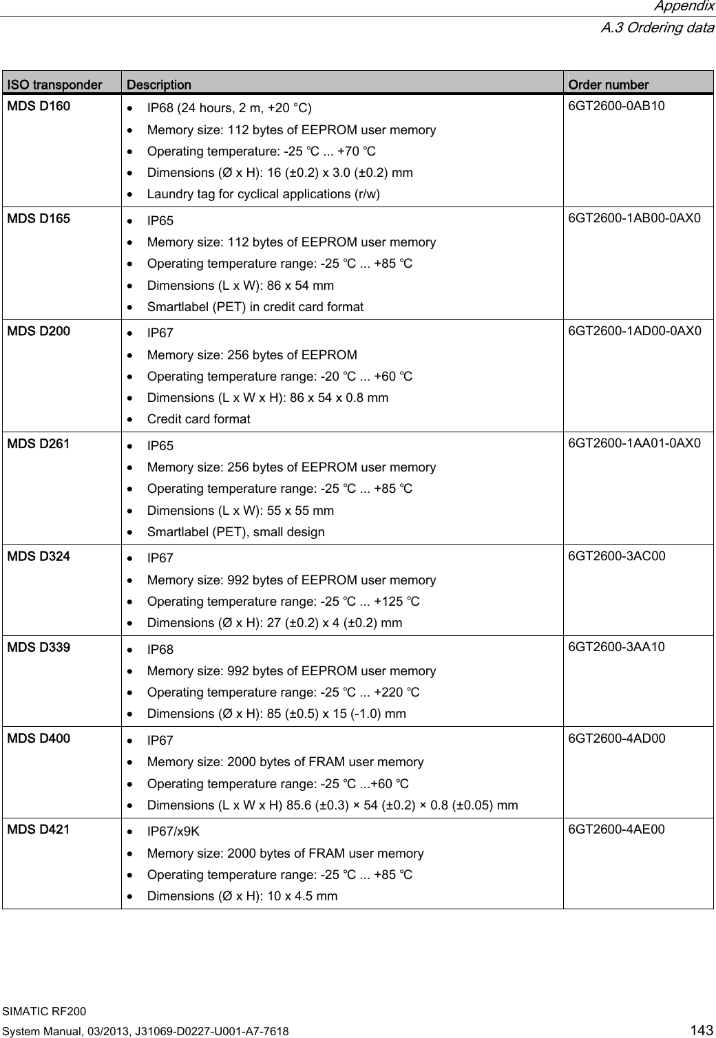
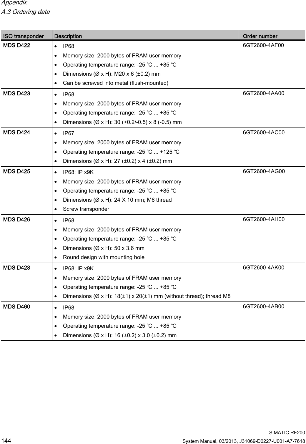
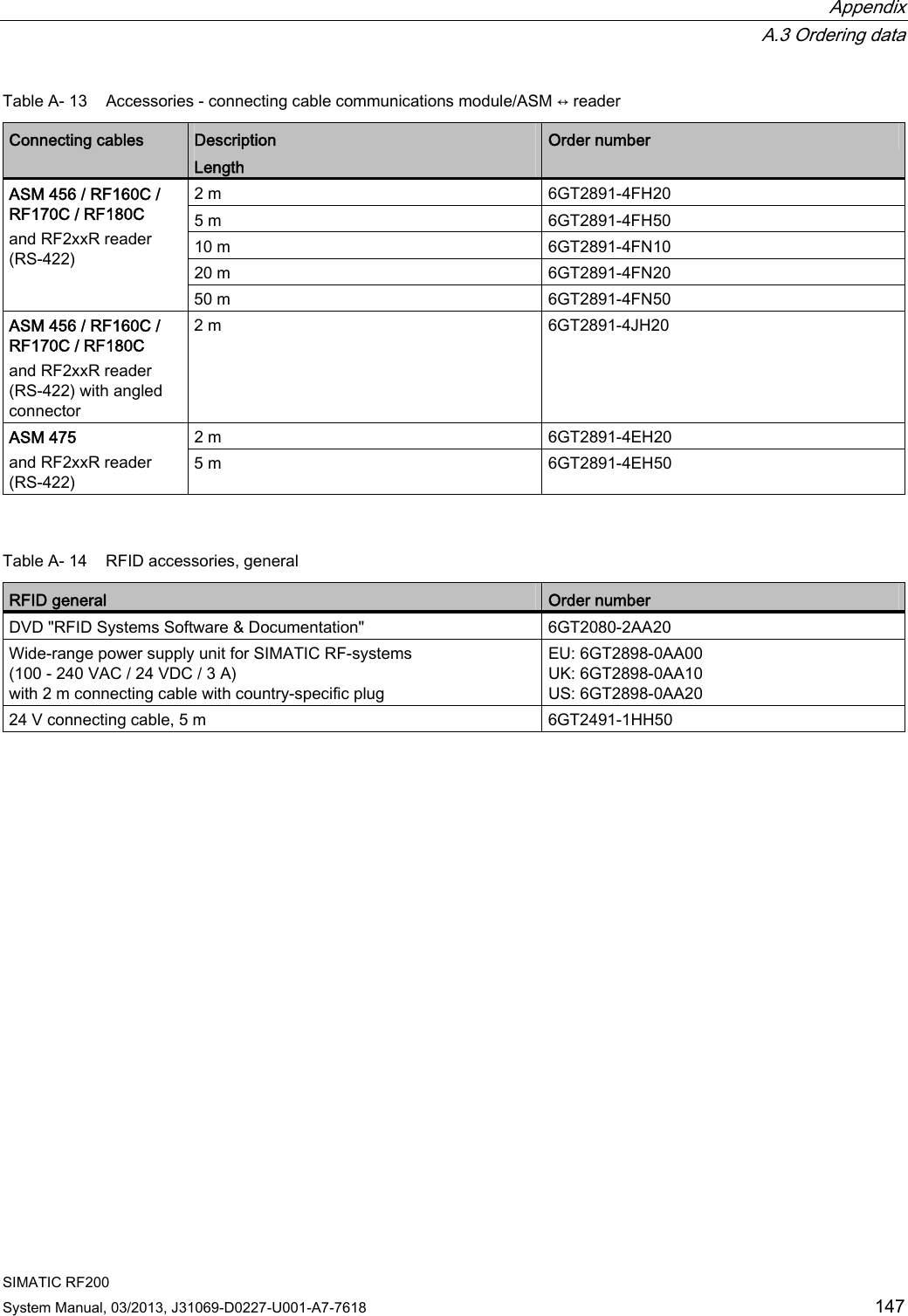
![Appendix A.3 Ordering data SIMATIC RF200 142 System Manual, 03/2013, J31069-D0227-U001-A7-7618 Readers Description Order number RF260R • With RS-232 interface (3964R) • IP67 • Operating temperature: -20 ℃ ... +70 ℃ • Dimensions (L x W x H): 75 x 75 x 41 mm • with integrated antenna 6GT2821-6AC11 RF290R • With RS-232 interface and RS-422 interface (3964R) • IP65 • Operating temperature: -20 ℃ ... +55 ℃ • Dimensions (L x W x H): 200 x 140 x 80 mm • Long-range reader with the option of connecting external antennas 6GT2821-0AC12 Table A- 6 ISO transponder ISO transponder Description Order number MDS D100 • IP68 • Memory size: 112 bytes of EEPROM user memory • Operating temperature range: -25 ℃ ... +80 ℃ • Dimensions (L x W x H): 85.6 (±0.2) x 54 (±0.2) x 0.9 (±0.05) mm • ISO card 6GT2600-0AD10 MDS D124 • IP67 • Memory size: 112 bytes of EEPROM user memory • Operating temperature range: -25 ℃ ... +125 ℃ • Dimensions (Ø x H): 27 (±0.2) x 4 (±0.2) mm 6GT2600-0AC10 MDS D126 • IP68 • Memory size: 112 bytes of EEPROM user memory • Operating temperature range: -25 ℃ ... +85 ℃ • Dimensions (Ø x H): 50 x 3.6 mm • Round design with mounting hole 6GT2600-0AE00 MDS D127 • IP68 • Memory size: 112 bytes of EEPROM user memory • Operating temperature range: -25 ℃ ... +125 ℃ • Dimensions (Ø x H): M6 x 5 (±0.2) mm 6GT2600-0AF00 MDS D139 • IP68 • Memory size: 112 bytes of EEPROM user memory • Operating temperature range: up to +200 °C/+220 °C [heat-resistant (r/w)] • Dimensions (Ø x H): 85 (±0.5) x 15 (-1.0) mm 6GT2600-0AA10](https://usermanual.wiki/Siemens/RF290R/User-Guide-1938433-Page-144.png)