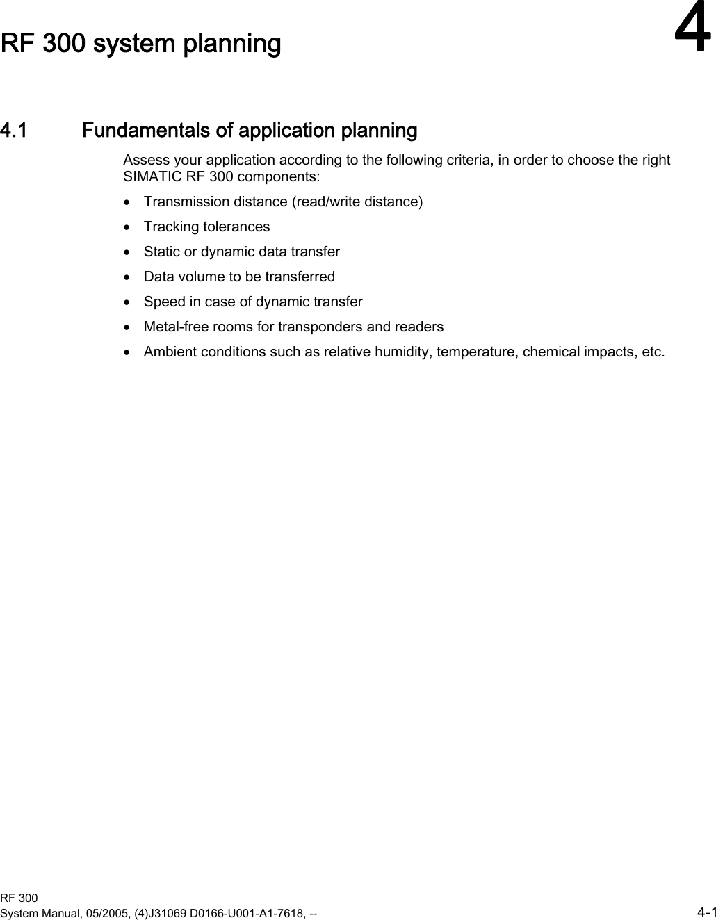
Siemens RF310R-IQ Inductive Tag Reader User Manual
Siemens AG Inductive Tag Reader
UserManual.wiki
>
Siemens
>
RF310R-IQ User Manual
>
Users Manual Part 1
Contents
1.
Users Manual Part 1
2.
Users Manual Part 2
Users Manual Part 1
Navigation menu
Upload a User Manual
Namespaces
Wiki Guide
HTML
PDF
Info
Views
User Manual
Discussion / Help
Navigation
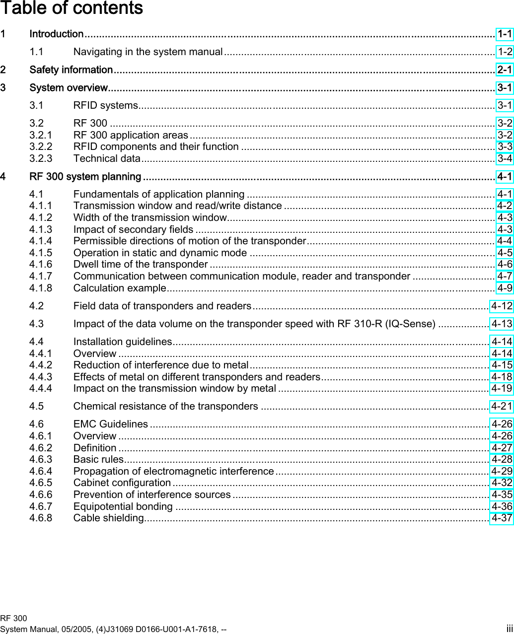

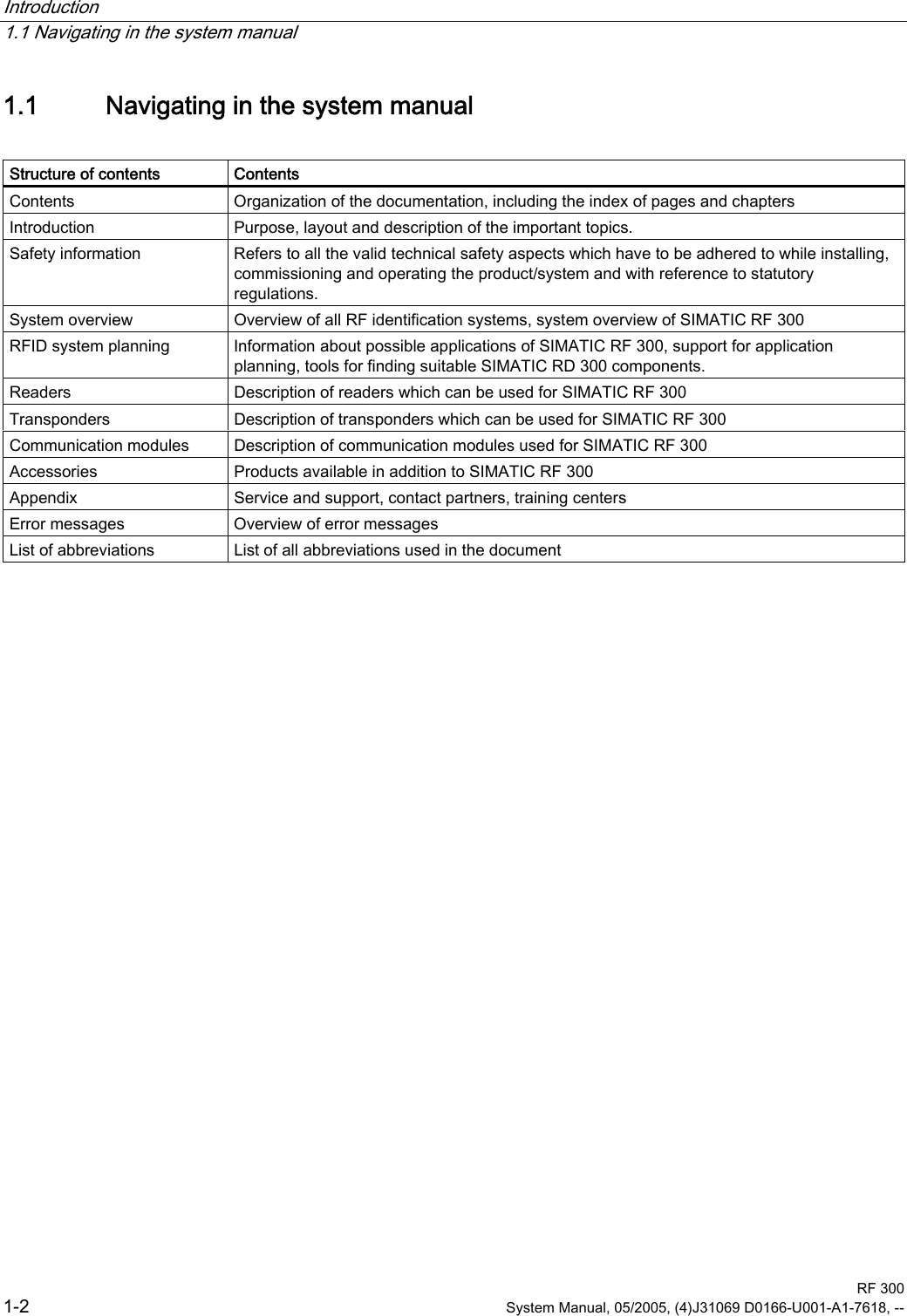
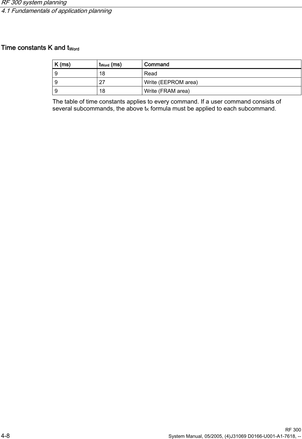
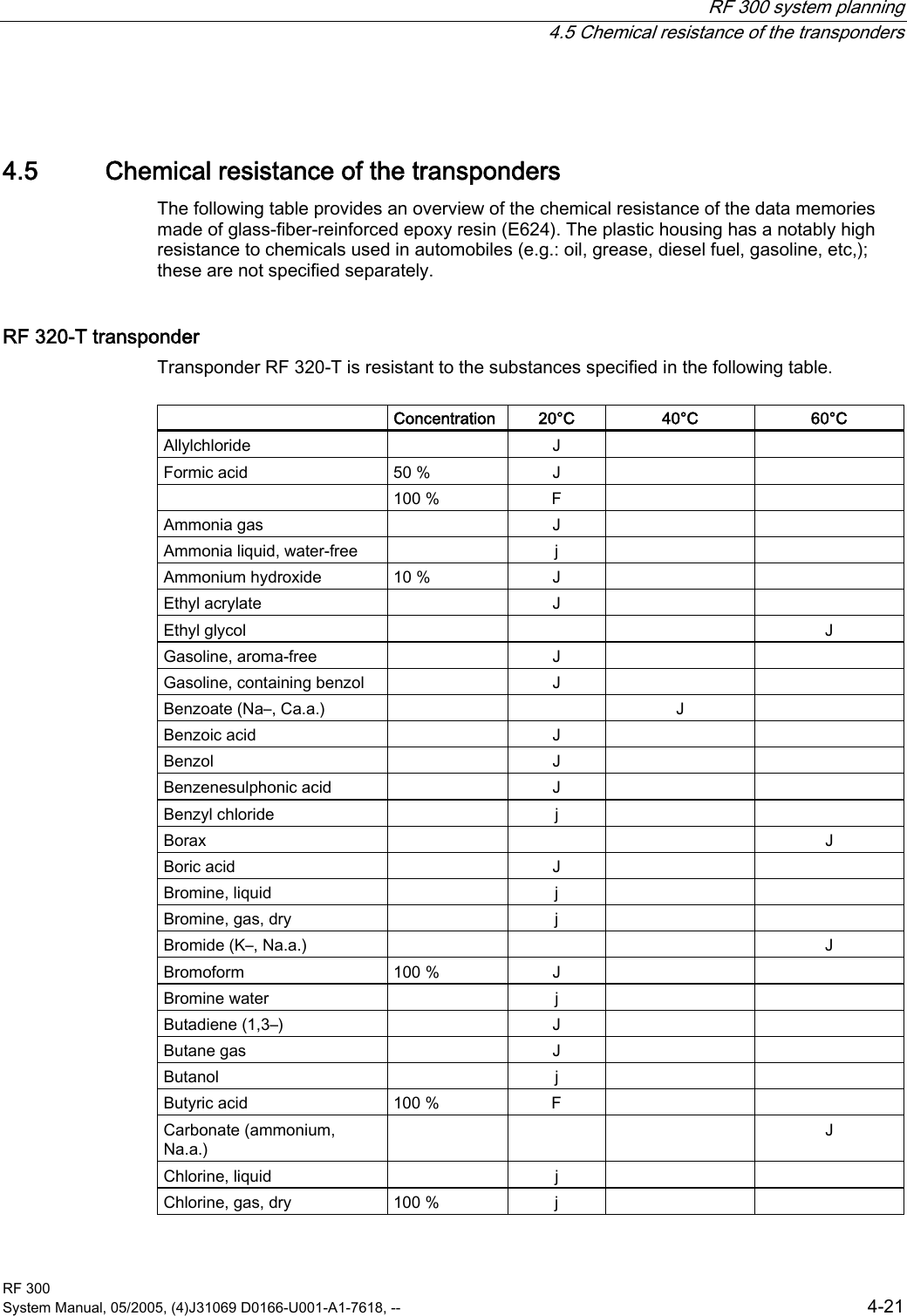
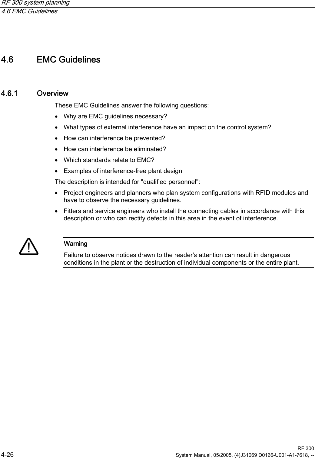
![System overview 3.2 RF 300 RF 300 System Manual, 05/2005, (4)J31069 D0166-U001-A1-7618, -- 3-3 3.2.2 RFID components and their function RF 300 system components 6HULDODV\QFKURQRXVLQWHUIDFH56565)7 5)73RZHUDQGGDWDWUDQVPLVVLRQ0+]5)5,46HQVHLQWHUIDFH+DQGWHUPLQDO[,46HQVHIRU(70RQ6ZLWK)&3&LQWHUIDFHWKLUGSDUW\3/&$60IRU6,0$7,&6$60IRU352),%86'395)7 5)7 5)7 5)75)5 5)5 5)5 5)5 Communication modules A communication module (interface module) is used to integrate the RF identification system in PLC/automation systems. In the case of SIMATIC RF 300, the reader is connected to an S7 automation system either via the 8xIQ-Sense module or an equivalent MOBY interface module (e.g. ASM 475). Readers The reader ensures inductive communication, supplies power to the transponders, and handles the connection to the various PLCs (e.g. SIMATIC S7). Transponders Transponders (mobile data memories) are used, for example, in place of barcodes and can contain all product-specific data in addition to the product number.](https://usermanual.wiki/Siemens/RF310R-IQ.Users-Manual-Part-1/User-Guide-610106-Page-15.png)
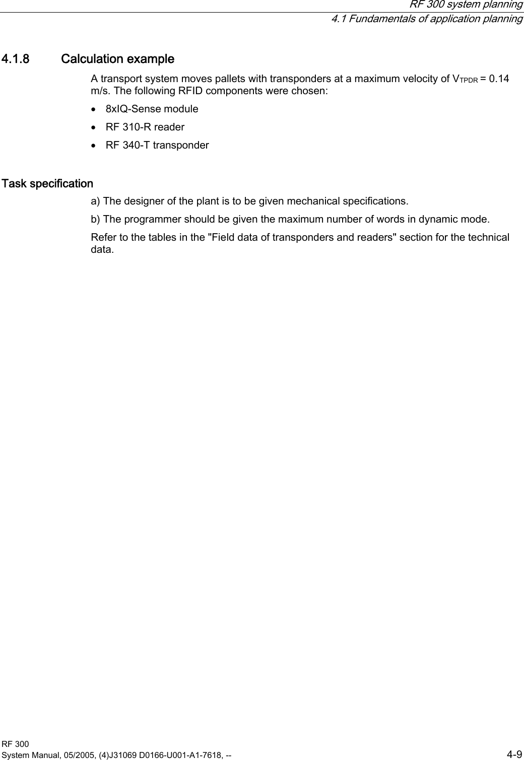
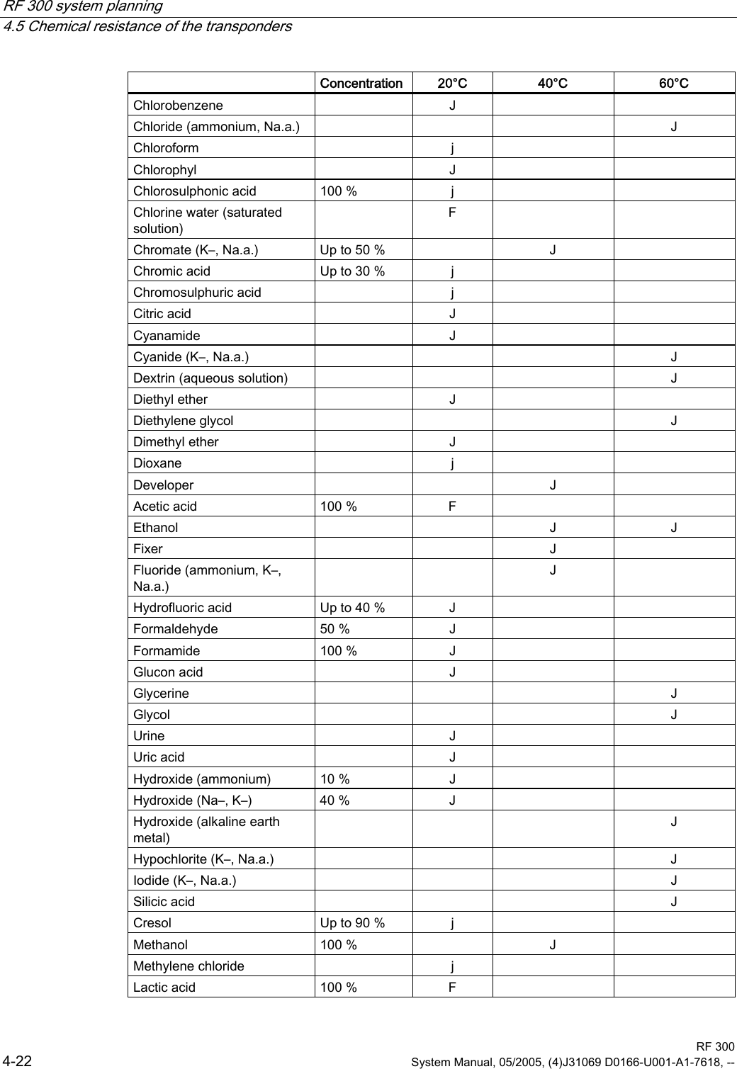
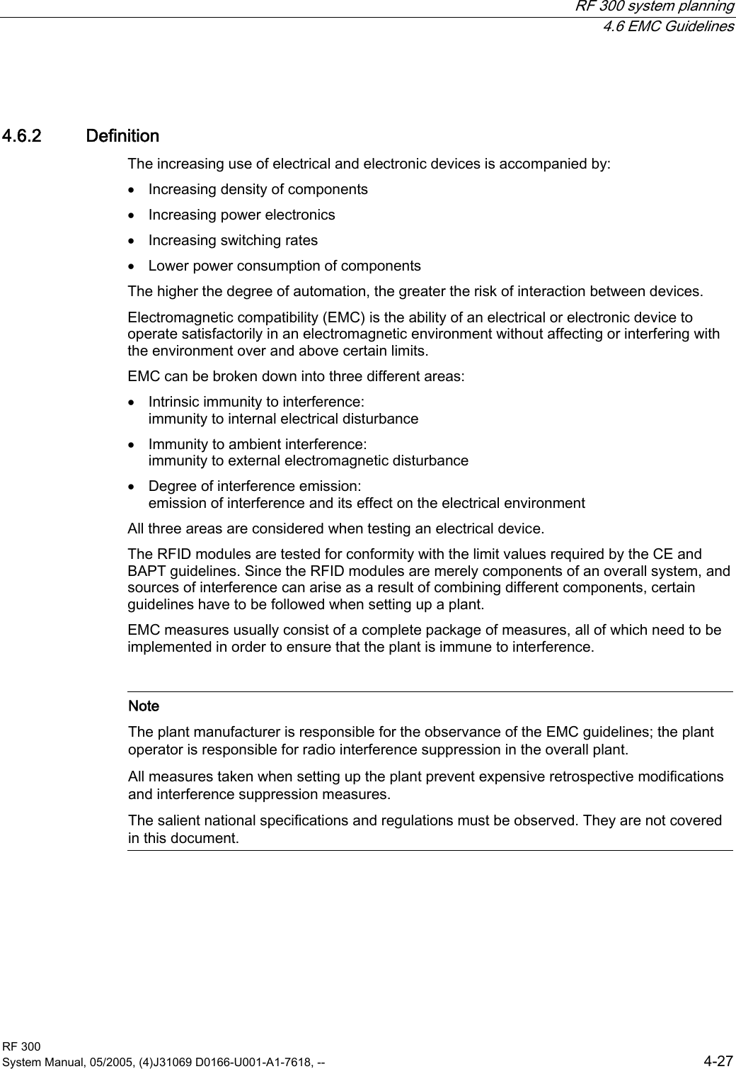
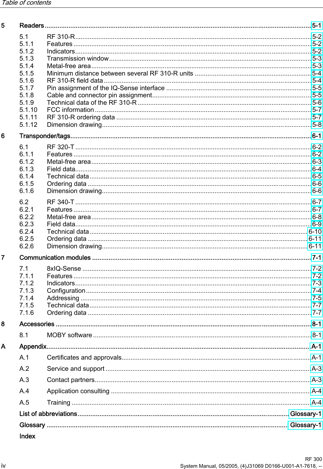
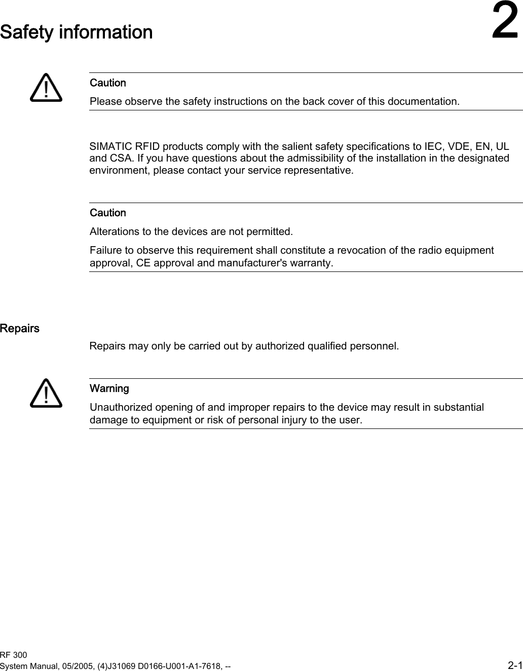
![RF 300 system planning 4.1 Fundamentals of application planning RF 300 4-6 System Manual, 05/2005, (4)J31069 D0166-U001-A1-7618, -- 4.1.6 Dwell time of the transponder The dwell time is the time in which the transponder dwells within the transmission window of a reader. The reader can exchange data with the transponder during this time. The dwell time is calculated thus: 0,8[ ][/]TPDRKLmtvms⋅= tV: Dwell time of the transponder L: Length of the transmission window vTPDR: Speed of the transponder (TPDR) in dynamic mode 0,8: Constant factor used to compensate for temperature impacts and production tolerances The dwell time can be of any duration in static mode. The dwell time must be sufficiently long to allow communication with the transponder. The dwell time is defined by the system environment in dynamic mode. The volume of data to be transferred must be matched to the dwell time or vice versa. In general: Kvtt≥ tV:: Dwell time of the data memory within the field of the reader tK: Communication time between transponder and communication module](https://usermanual.wiki/Siemens/RF310R-IQ.Users-Manual-Part-1/User-Guide-610106-Page-22.png)