Siemens RF310R-IQ Inductive Tag Reader User Manual
Siemens AG Inductive Tag Reader
UserManual.wiki
>
Siemens
>
RF310R-IQ User Manual
>
Users Manual Part 2
Contents
1.
Users Manual Part 1
2.
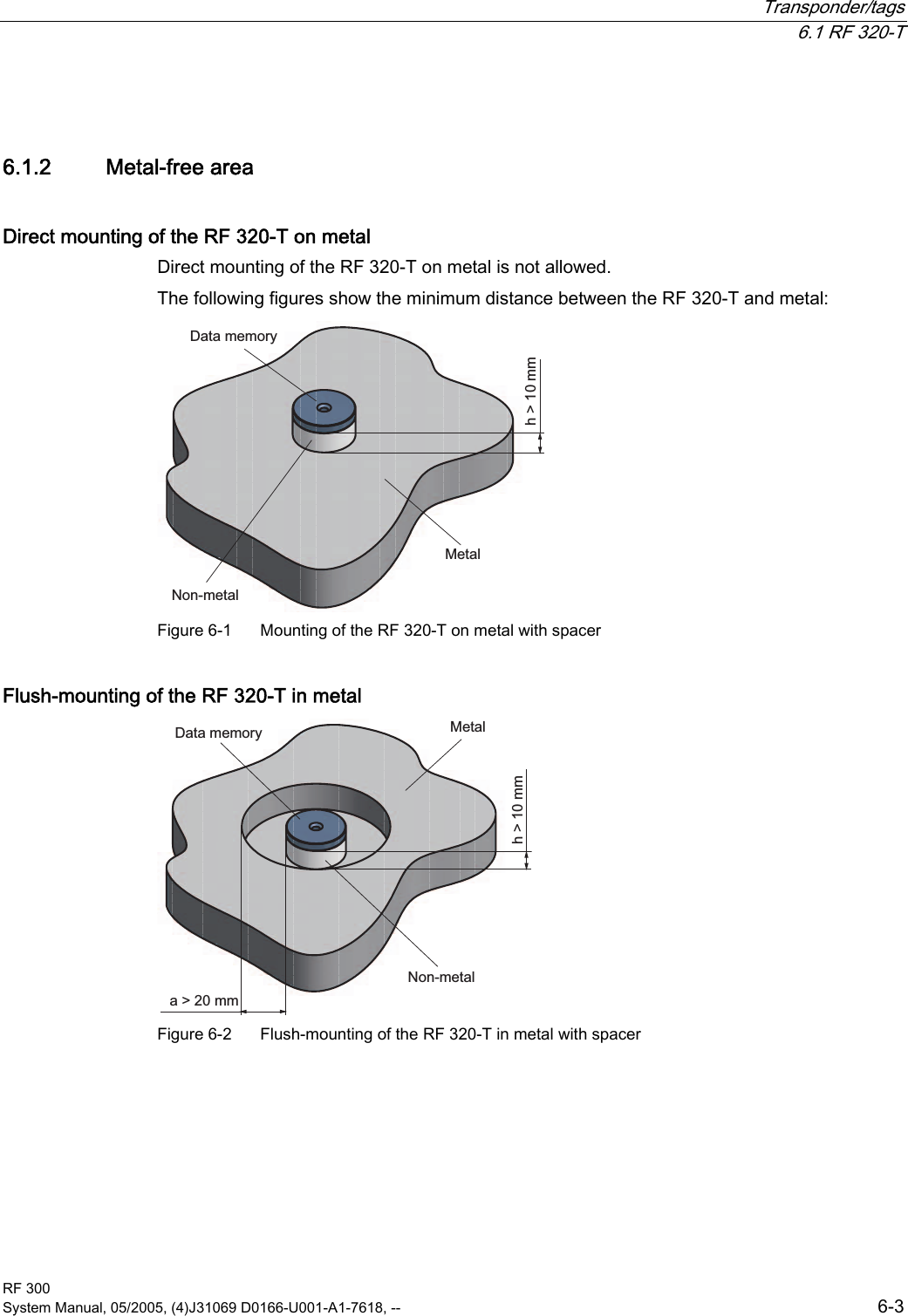
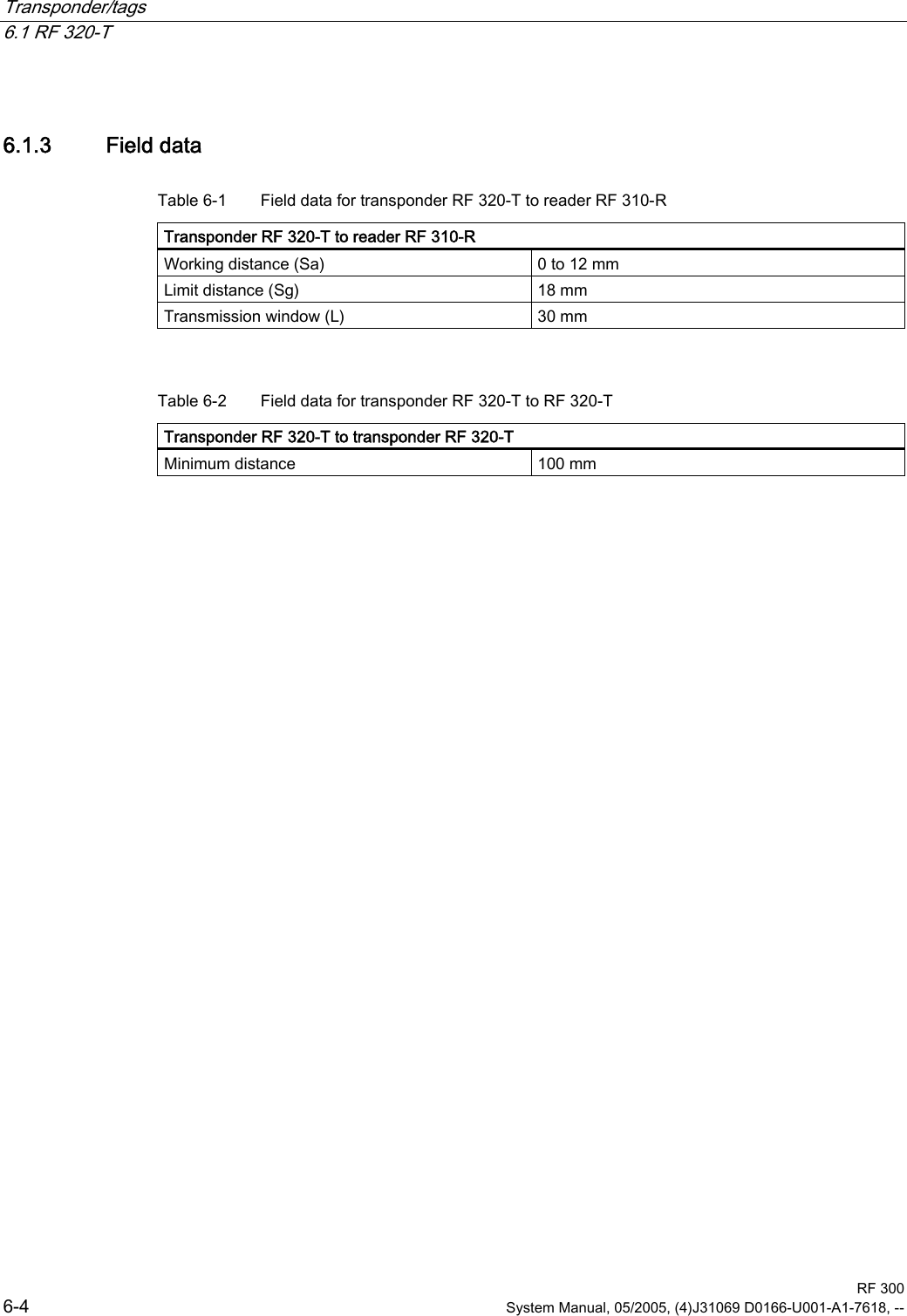
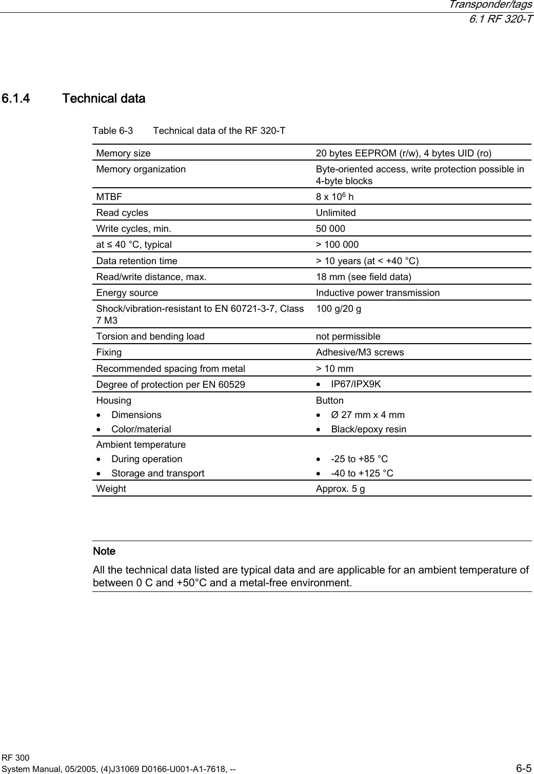
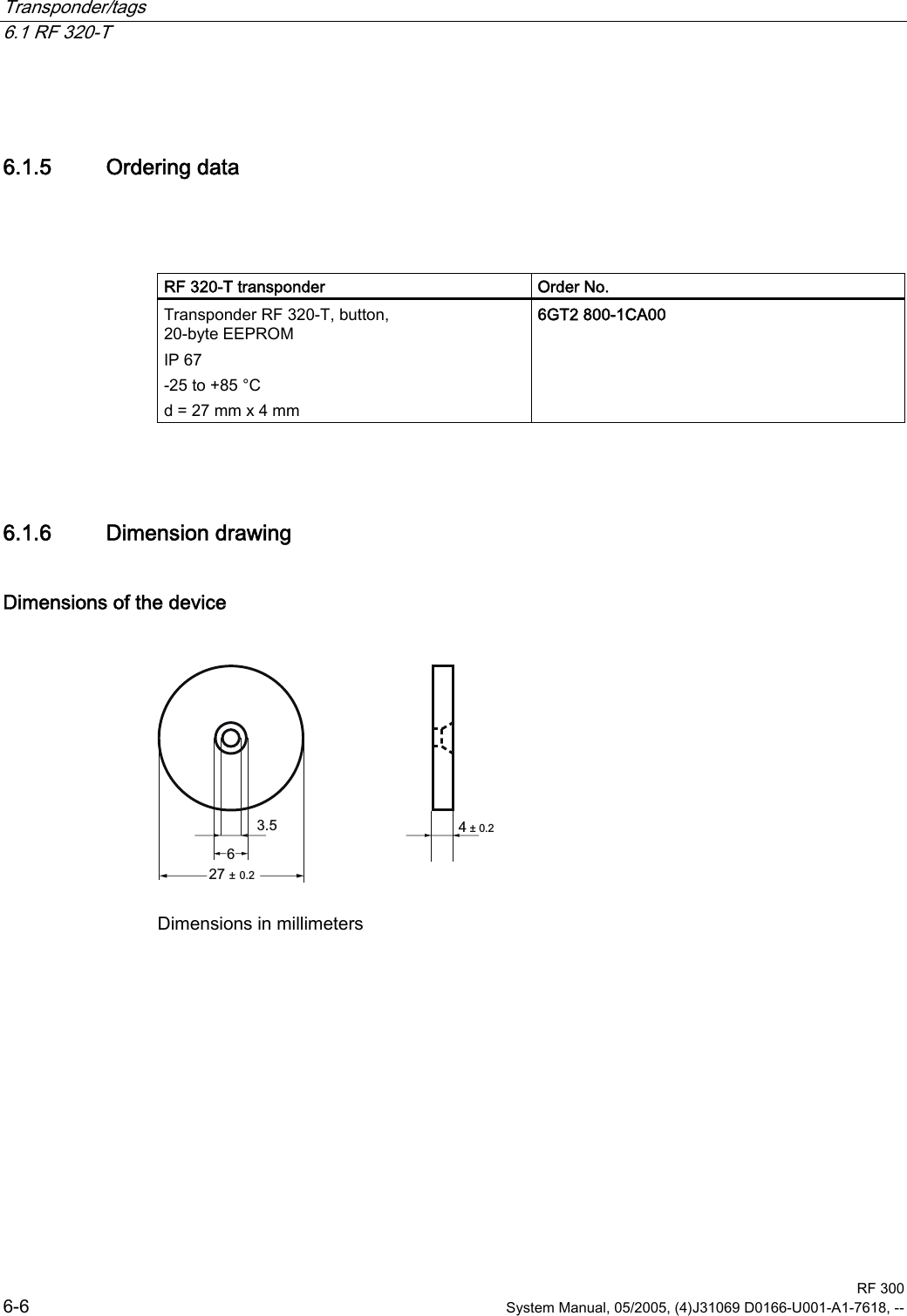
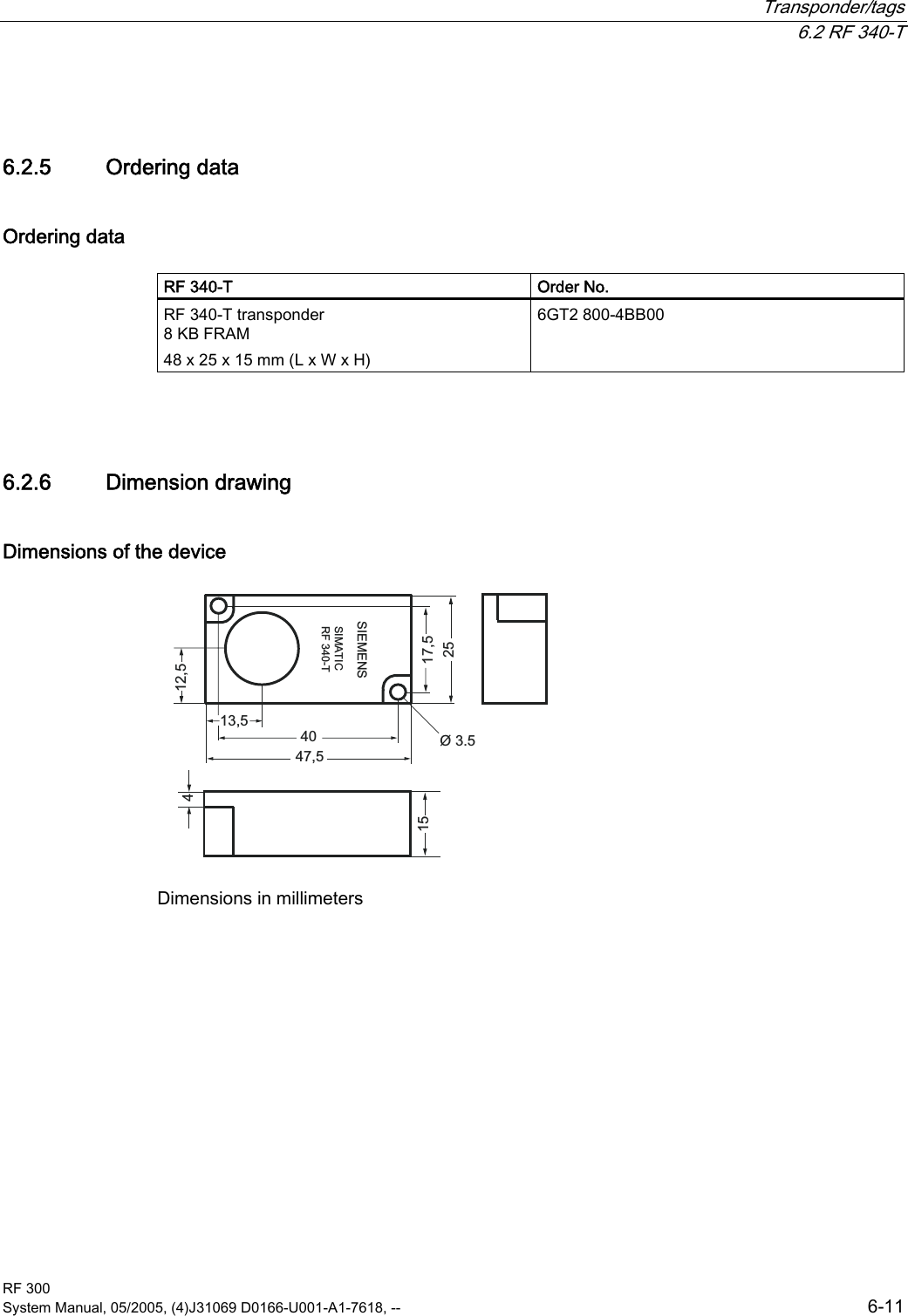
Users Manual Part 2
Users Manual Part 2
Navigation menu
Upload a User Manual
Namespaces
Wiki Guide
HTML
PDF
Info
Views
User Manual
Discussion / Help
Navigation
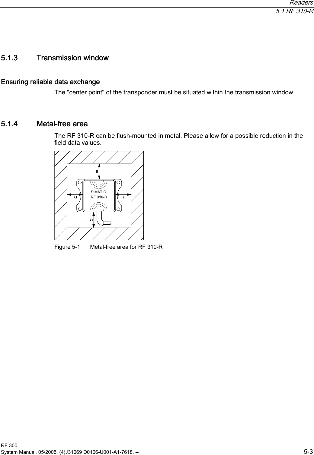
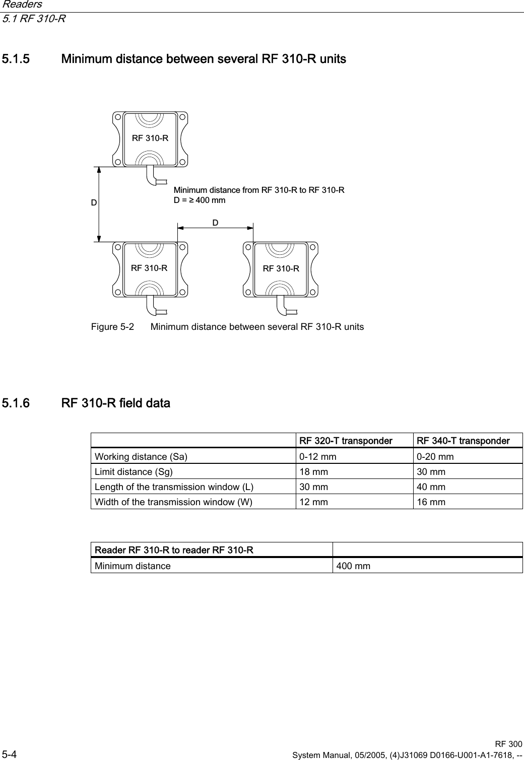
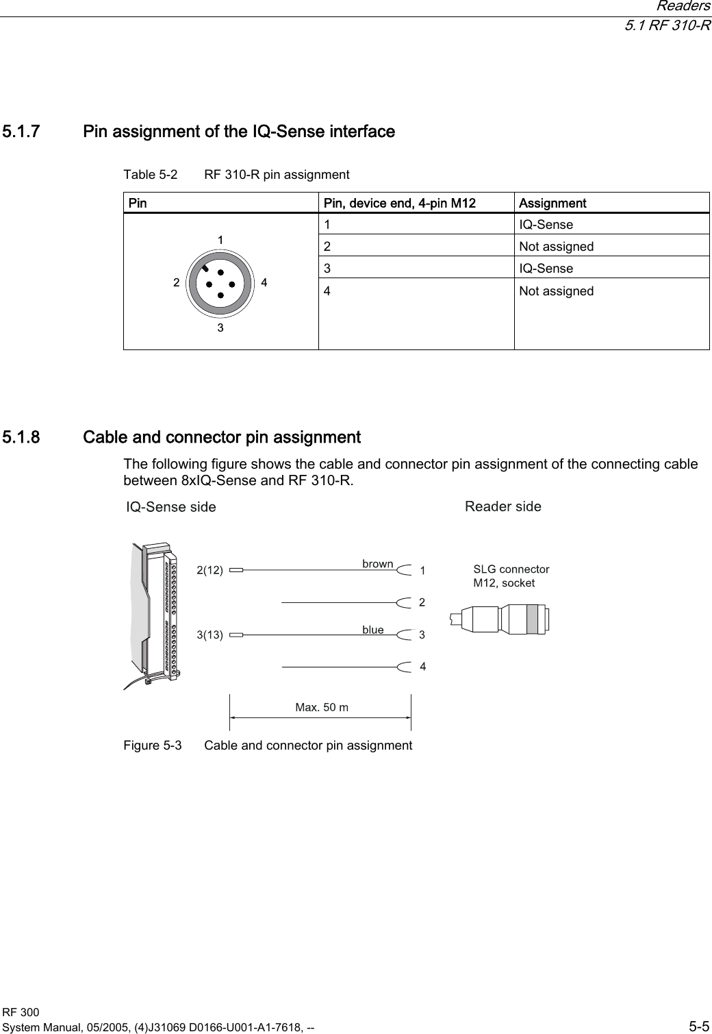
![List of abbreviations RF 300 Glossary-2 System Manual, 05/2005, (4)J31069 D0166-U001-A1-7618, -- Sg Limit distance SLG Write/read device SP Intersection of the axes of symmetry of the MDS Tag See transponder TPDR Transponder UL Underwriter Laboratories, USA VDE Verband Deutscher Elektrotechniker [Association of German Electrical Engineers] XPDR Transponder](https://usermanual.wiki/Siemens/RF310R-IQ.Users-Manual-Part-2/User-Guide-610107-Page-40.png)