Siemens RF340R Inductive Tag Reader User Manual RFID Systeme SIMATIC RF300
Siemens AG Inductive Tag Reader RFID Systeme SIMATIC RF300
Siemens >
Contents
- 1. Manual Part 1
- 2. Manual Part 2
- 3. Manual Part 3
Manual Part 2
RF300 system planning
4.6 EMC Directives
SIMATIC RF300
System Manual, Release 04/2006, J31069 D0166-U001-A2-7618 4-51
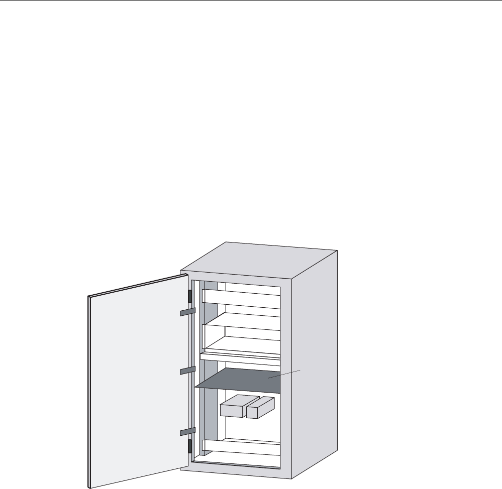
Prevention of interference by optimum configuration
Good interference suppression can be achieved by installing SIMATIC PLCs on conducting
mounting plates (unpainted). When setting up the control cabinet, interference can be
prevented easily by observing certain guidelines. Power components (transformers, drive
units, load power supply units) should be arranged separately from the control components
(relay control unit, SIMATIC S7).
As a rule:
• The effect of the interference decreases as the distance between the interference source
and interference sink increases.
• The interference can be further decreased by installing grounded shielding plates.
• The load connections and power cables should be installed separately from the signal
cables with a minimum clearance of 10 cm.
3RZHUVXSSO\
&&(8
'ULYH
6KLHOG
SODWH
Figure 4-24 Prevention of interference by optimum configuration
RF300 system planning
4.6 EMC Directives
SIMATIC RF300
4-52 System Manual, Release 04/2006, J31069 D0166-U001-A2-7618
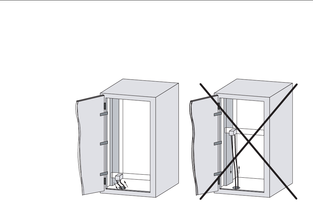
Filtering of the supply voltage
External interference from the mains can be prevented by installing line filters. Correct
installation is extremely important, in addition to appropriate dimensioning. It is essential that
the line filter is mounted directly at the cabinet inlet. As a result, interference is filtered
promptly at the inlet, and is not conducted through the cabinet.
/LQHILOWHU
,V
&RUUHFW
/LQHILOWHU
,QFRUUHFW
,F LQWHUIHUHQFHFXUUHQW
,V
Figure 4-25 Filtering of the supply voltage
RF300 system planning
4.6 EMC Directives
SIMATIC RF300
System Manual, Release 04/2006, J31069 D0166-U001-A2-7618 4-53
4.6.6 Prevention of interference sources
A high level of immunity to interference can be achieved by avoiding interference sources.
All switched inductances are frequent sources of interference in plants.
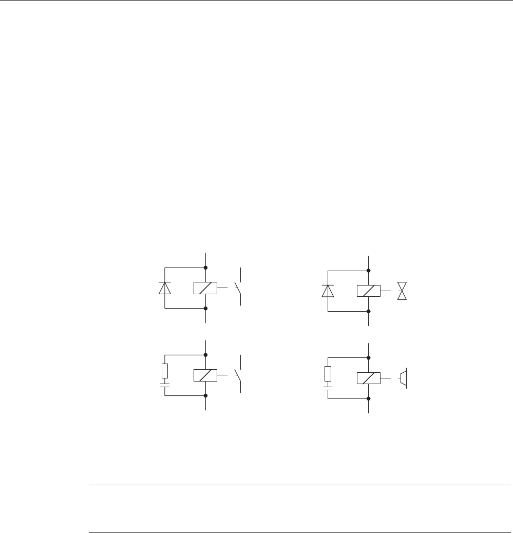
Suppression of inductance
Relays, contactors, etc. generate interference voltages and must therefore be suppressed
using one of the circuits below.
Even with small relays, interference voltages of up to 800 V occur on 24 V coils, and
interference voltages of several kV occur on 230 V coils when the coil is switched. The use
of freewheeling diodes or RC circuits prevents interference voltages and thus stray
interference on conductors installed parallel to the coil conductor.
9DOYHV
%UDNHV
5HOD\FRLOV
&RQWDFWRUV
Figure 4-26 Suppression of inductance
Note
All coils in the cabinet should be suppressed. The valves and motor brakes are frequently
forgotten. Fluorescent lamps in the control cabinet should be tested in particular.
RF300 system planning
4.6 EMC Directives
SIMATIC RF300
4-54 System Manual, Release 04/2006, J31069 D0166-U001-A2-7618
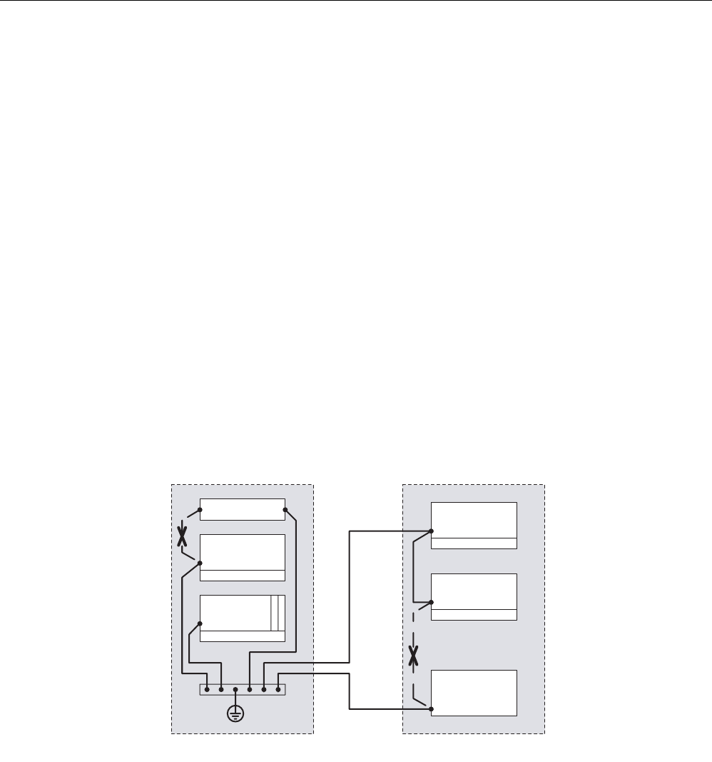
4.6.7 Equipotential bonding
Potential differences between different parts of a plant can arise due to the different design
of the plant components and different voltage levels. If the plant components are connected
across signal cables, transient currents flow across the signal cables. These transient
currents can corrupt the signals.
Proper equipotential bonding is thus essential.
• The equipotential bonding conductor must have a sufficiently large cross section (at least
10 mm2).
• The distance between the signal cable and the associated equipotential bonding
conductor must be as small as possible (antenna effect).
• A fine-strand conductor must be used (better high-frequency conductivity).
• When connecting the equipotential bonding conductors to the centralized equipotential
bonding strip (EBS), the power components and non-power components must be
combined.
• The equipotential bonding conductors of the separate modules must lead directly to the
equipotential bonding strip.
&DELQHW &DELQHW
,QFRUUHFW
3RZHUVXSSO\
'ULYH
'HYLFH
3/&
(%6
'HYLFH
'HYLFH
,QFRUUHFW
Figure 4-27 Equipotential bonding (EBS = Equipotential bonding strip)
The better the equipotential bonding in a plant, the smaller the chance of interference due to
fluctuations in potential.
Equipotential bonding should not be confused with protective earthing of a plant. Protective
earthing prevents the occurrence of excessive shock voltages in the event of equipment
faults whereas equipotential bonding prevents the occurrence of differences in potential.
RF300 system planning
4.6 EMC Directives
SIMATIC RF300
System Manual, Release 04/2006, J31069 D0166-U001-A2-7618 4-55
4.6.8 Cable shielding
Signal cables must be shielded in order to prevent coupling of interference.
The best shielding is achieved by installing the cables in steel tubes. However, this is only
necessary if the signal cable is routed through an environment prone to particular
interference. It is usually adequate to use cables with braided shields. In either case,
however, correct connection is vital for effective shielding.
Note
An unconnected or incorrectly connected shield has no shielding effect.
As a rule:
• For analog signal cables, the shield should be connected at one end on the receiver side
• For digital signals, the shield should be connected to the enclosure at both ends
• Since interference signals are frequently within the HF range (> 10 kHz), a large-area HF-
proof shield contact is necessary
Figure 4-28 Cable shielding
RF300 system planning
4.6 EMC Directives
SIMATIC RF300
4-56 System Manual, Release 04/2006, J31069 D0166-U001-A2-7618
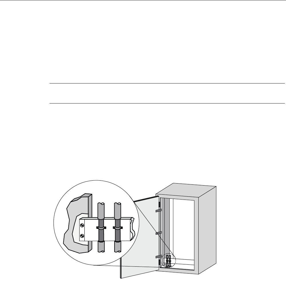
The shielding bus should be connected to the control cabinet enclosure in a manner allowing
good conductance (large-area contact) and must be situated as close as possible to the
cable inlet. The cable insulation must be removed and the cable clamped to the shielding
bus (high-frequency clamp) or secured using cable ties. Care should be taken to ensure that
the connection allows good conductance.
Cable tie
5HPRYHSDLQW
Figure 4-29 Connection of shielding bus
The shielding bus must be connected to the PE busbar.
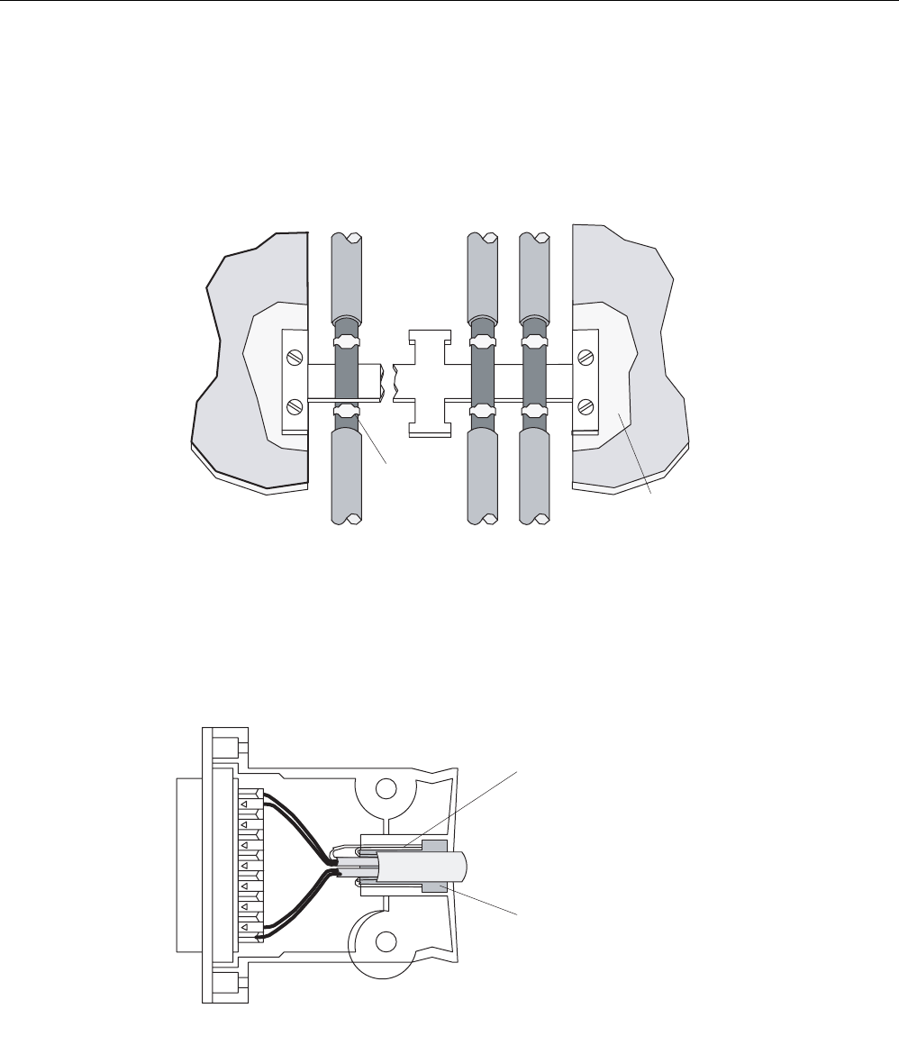
If shielded cables have to be interrupted, the shield must be continued via the corresponding
connector housing. Only suitable connectors may be used for this purpose.
6KLHOGWXUQHGXSVLGHGRZQ
WKURXJKrDQG
FRQQHFWHGWRFRQQHFWRU
KRXVLQJ
5XEEHUVOHHYH
Figure 4-30 Interruption of shielded cables
If intermediate connectors, which do not have a suitable shield connection, are used, the
shield must be continued by fixing cable clamps at the point of interruption. This ensures a
large-area, HF-conducting contact.
SIMATIC RF300
System Manual, Release 04/2006, J31069 D0166-U001-A2-7618 5-1
Readers 5
5.1 5.1 Overview
The reader ensures inductive communication with the transponders, and handles the serial
connection to the communication modules/interface modules and 8xIQ-Sense module.
Communication between the transponder and reader takes place over inductive alternating
fields.
The transmittable data volume between reader and transponder depends on:
• the speed at which the transponder moves through the transmission window of the
reader.
• the length of the transmission window.
• the transponder type (FRAM, EEPROM).
Readers
5.2 RF310R with IQ-Sense interface
SIMATIC RF300
5-2 System Manual, Release 04/2006, J31069 D0166-U001-A2-7618
5.2 5.2 RF310R with IQ-Sense interface
5.2.1 Features
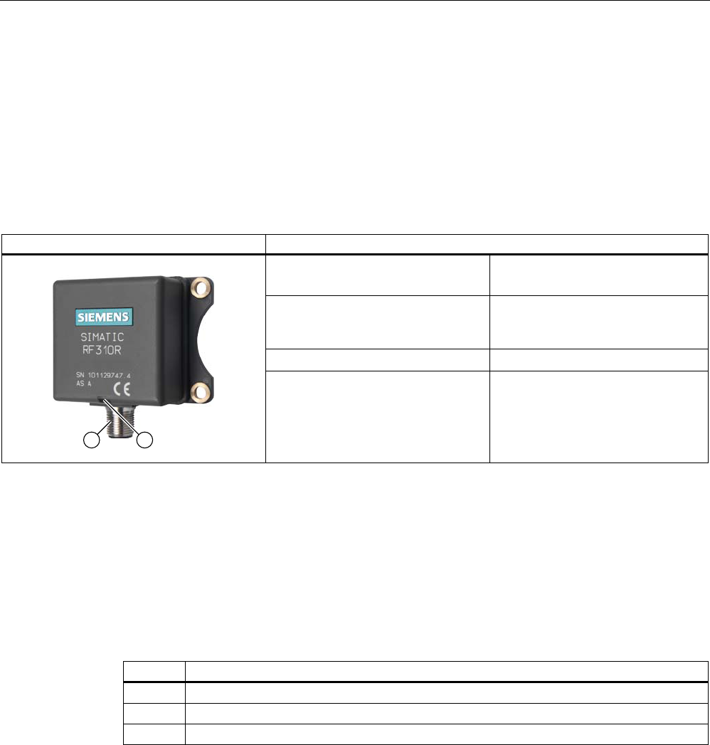
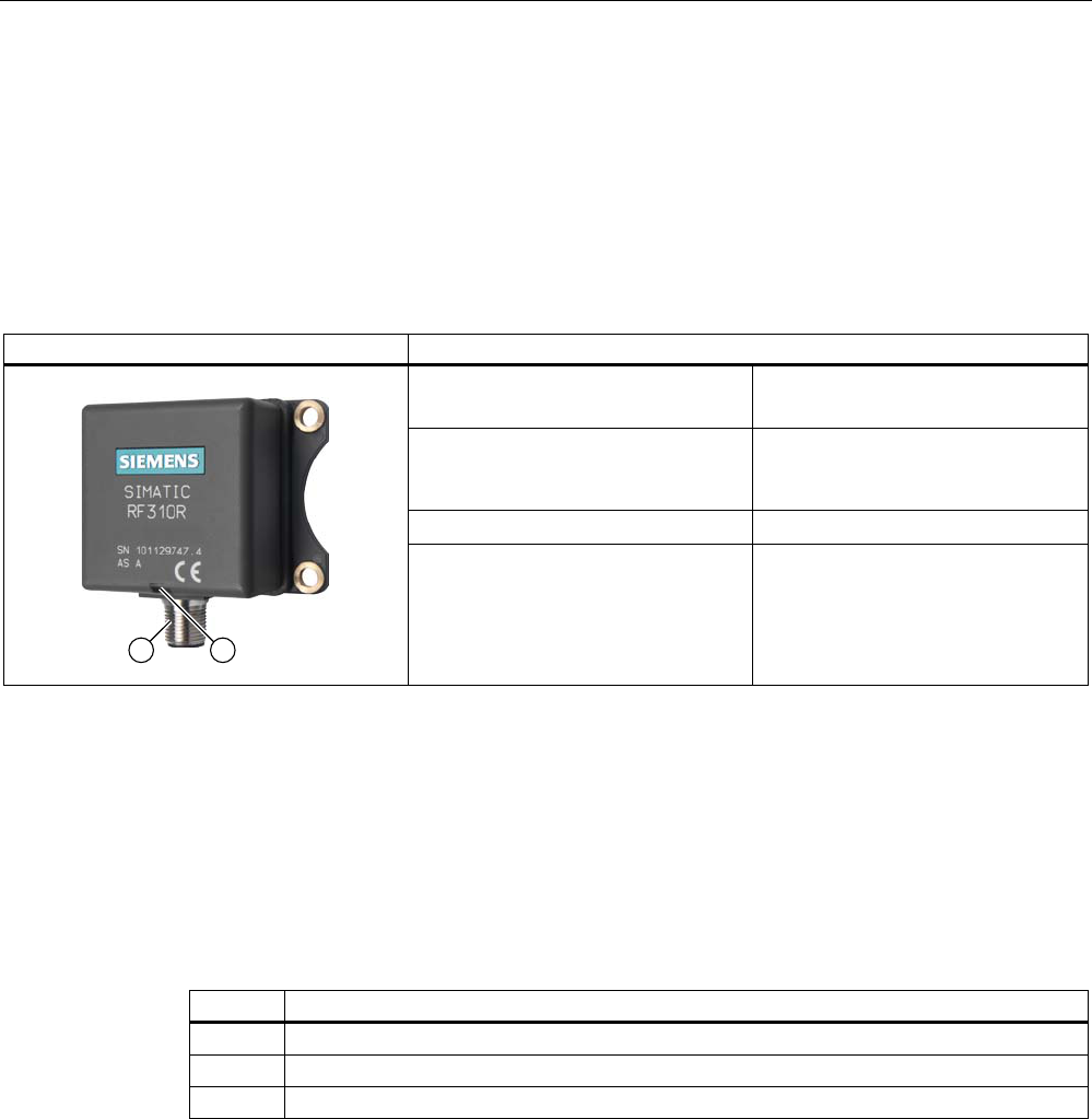
Reader RF310R Features
Design (1) IQ-Sense interface
(2) Operating indicator
Field of application Identification tasks on small
assembly lines in harsh industrial
environments
Read/write distance to transponder max. 30 mm
Data transmission rate • Read: approx. 50 bytes/s
• Write: approx. 40 bytes/s
5.2.2 Display elements of the RF310R reader with IQ-Sense interface
Table 5-1 Display elements of the reader
Color Meaning
Green Operating voltage available
yellow Transponder present
red Errors
5.2.3 Ensuring reliable data exchange
The "center point" of the transponder must be situated within the transmission window.
Readers
5.2 RF310R with IQ-Sense interface
SIMATIC RF300
System Manual, Release 04/2006, J31069 D0166-U001-A2-7618 5-3
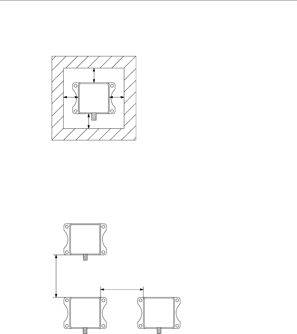
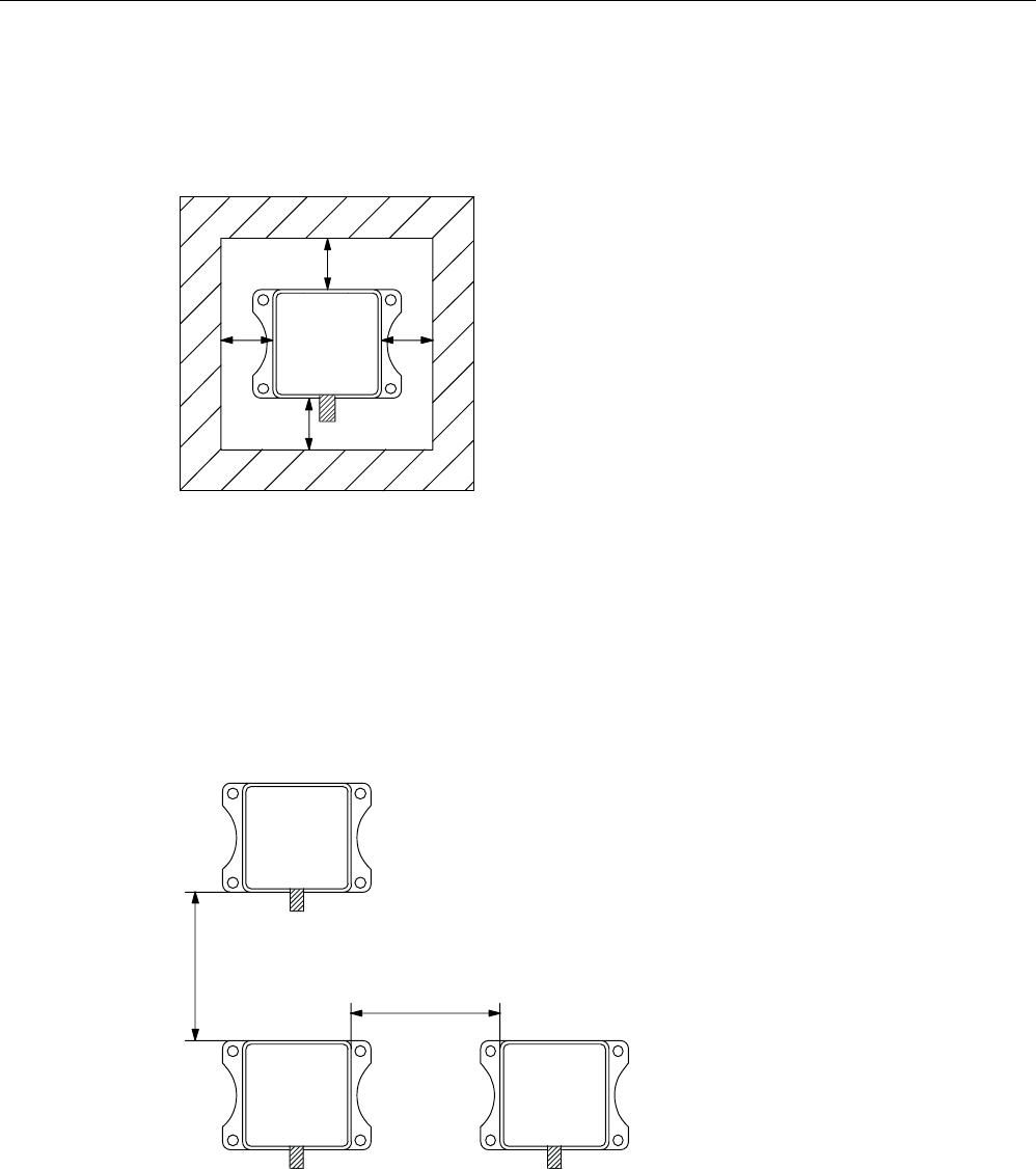
5.2.4 Metal-free area
The RF310R can be flush-mounted in metal. Please allow for a possible reduction in the field
data values.
D
D
DD
6,0$7,&
5)5
Figure 5-1 Metal-free area for RF310R
To avoid any impact on the field data, the distance a should be ≥ 20 mm.
5.2.5 Minimum distance between RF310R readers
ุPP
0LQLPXPGLVWDQFHEHWZHHQ5)5DQG5)5
'
'
'
5)5
6,0$7,&
5)5
6,0$7,&
5)5
6,0$7,&
Figure 5-2 Minimum distance between RF310R readers

Readers
5.2 RF310R with IQ-Sense interface
SIMATIC RF300
5-4 System Manual, Release 04/2006, J31069 D0166-U001-A2-7618
5.2.6 Technical data for RF310R reader with IQ-Sense interface
Table 5-2 Technical data for RF310R reader with IQ-Sense interface
Inductive interface to the transponder
Transmission frequency for power/data
13.56 MHz
Interface to SIMATIC S7-300
Required master module
RFID channels (RF310R)
Mixed operation with other profiles
IQ-Sense, 2-wire non-polarized
8-IQ-Sense (6ES7 338-7XF00-0AB0)
max. 2 per master module,
max. 4 Opto-BEROs, 1x SIMATIC RF310R
Cable length between reader and communication
module
Max. 50 m (unshielded cable)
Read/write distances of reader See RF310R field data
Minimum distance between two RF310R readers ≥ 400 mm
Data transfer rate for read/write device
Reading
Writing
Approx. 50 bytes/s
Approx. 40 bytes/s
Passing speed
Reading
Writing
Approx. 0.8 m/s (2 bytes)
Approx. 0.8 m/s (2 bytes)
Function Read, write, initialize transponder
Multi-tag no
Voltage supply via IQ-Sense master module 24 V DC
Display elements 2-color LED (operating voltage,
presence, error)
Plug connector M12 (4-pin)
Enclosure
Dimensions (in mm)
Color
Material
55 x 75 x 30 (without M12 enclosure connector)
Anthracite
Plastic PA 12
Fixing 4 x M5 screws
Ambient temperature
during operations
during transport and storage
-25°C to +70°C
-40°C to +85°C
Degree of protection to EN 60529
Shock to EN 60 721-3-7 Class 7 M2
Overall shock response spectrum, Type II
Vibration to EN 60 721-3-7 Class 7M2
IP65
50 g
1 g (9 to 200 Hz)
1.5 g (200 to 500 Hz)
Weight Approx. 200 g
MTBF (Mean Time Between Failures) in years 153,5
Approvals Radio to R&TTE guidelines EN 300 330,
EN 301 489, CE, FCC

Readers
5.2 RF310R with IQ-Sense interface
SIMATIC RF300
System Manual, Release 04/2006, J31069 D0166-U001-A2-7618 5-5
5.2.7 FCC information
Siemens SIMATIC RF300 with IQ-Sense interface
FCC ID: NXW-RF310R-IQ
This device complies with Part 15 of the FCC Rules. Operation is subject to the following two
conditions:
(1) This device may not cause harmful interference.
(2) This device must accept any interference received, including interference that may cause
undesired operation.
Caution
Any changes or modifications not expressly approved by the party responsible for
compliance could void the user's authority to operate the equipment.
5.2.8 Ordering data of RF310R with IQ-Sense interface
RF310R Order No.
With IQ-Sense interface
for ET 200M to SIMATIC S7-300
IP65, -25° to +70°C, 71 x 75 x 30 (L x W x H in mm), with integrated
antenna, max. limit distance: 30 mm (depending on transponder)
6GT2801-0AA00

Readers
5.2 RF310R with IQ-Sense interface
SIMATIC RF300
5-6 System Manual, Release 04/2006, J31069 D0166-U001-A2-7618
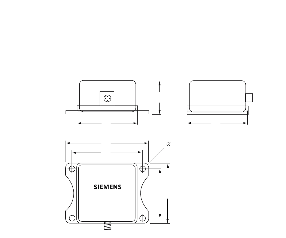
5.2.9 Dimension drawing
6,0$7,&
5)5
Figure 5-3 Dimension drawing for RF310R
Readers
5.3 RF310R with RS 422 interface
SIMATIC RF300
System Manual, Release 04/2006, J31069 D0166-U001-A2-7618 5-7
5.3 5.3 RF310R with RS 422 interface
5.3.1 Features
Reader RF310R Features
Structure (1) RS 422 interface
(2) Operating indicator
Field of application Identification tasks on small
assembly lines in harsh industrial
environments
Read/write distance to transponder max. 30 mm
Data transmission rate • Read: approx. 3100 bytes/s
• Write: approx. 3100 bytes/s
5.3.2 Display elements of the RF310R reader with RS 422 interface
Table 5-3 Display elements of the reader
Color Meaning
Green Operating voltage available
yellow Transponder present
red Errors
5.3.3 Ensuring reliable data exchange
The "center point" of the transponder must be situated within the transmission window.
Readers
5.3 RF310R with RS 422 interface
SIMATIC RF300
5-8 System Manual, Release 04/2006, J31069 D0166-U001-A2-7618
5.3.4 Metal-free area
The RF310R can be flush-mounted in metal. Please allow for a possible reduction in the field
data values.
D
D
DD
6,0$7,&
5)5
Figure 5-4 Metal-free area for RF310R
To avoid any impact on the field data, the distance a should be ≥ 20 mm.
5.3.5 Minimum distance between RF310R readers
ุPP
0LQLPXPGLVWDQFHEHWZHHQ5)5DQG5)5
'
'
'
5)5
6,0$7,&
5)5
6,0$7,&
5)5
6,0$7,&
Figure 5-5 Minimum distance between RF310R readers

Readers
5.3 RF310R with RS 422 interface
SIMATIC RF300
System Manual, Release 04/2006, J31069 D0166-U001-A2-7618 5-9
5.3.6 Technical data of the RF310R reader with RS 422 interface
Table 5-4 Technical data of the RF310R reader with RS 422 interface
Inductive interface to the transponder
Transmission frequency for power/data
13.56 MHz
Antenna Integrated
Interface to communication module RS 422 (3964R protocol)
Baud rate 19200 baud, 57600 baud, 115200 baud
Cable length between reader and communication
module
Max. 120 m
Data cable length max. 1000 m
(shielded cable)
Read/write distances of reader See RF310R field data
Minimum distance between two RF310R readers ≥ 400 mm
Maximum data transfer rate from reader to
transponder (Tag)
Reading
Writing
Approx. 3100 bytes/s
Approx. 3100 bytes/s
Functions Initialize/read/write transponder
Scan status and diagnostics information
Switch antenna on/off
Repeat command
Scan transponder serial numbers
Voltage supply 24 V DC, 30 mA typ.
Display elements 2-color LED (operating voltage,
presence, error)
Plug connector M12 (8-pin)
Enclosure
Dimensions (in mm)
Color
Material
55 x 75 x 30 (without M12 device connector)
Anthracite
Plastic PA 12
Fixing 4 x M5 screws
Ambient temperature
during operations
during transport and storage
-25 °C to +70 °C
-40 °C to +85 °C
Degree of protection to EN 60529
Shock to EN 60 721-3-7 Class 7 M2
Overall shock response spectrum, Type II
Vibration to EN 60 721-3-7 Class 7 M2
IP65
50 g
1 g (9 to 200 Hz)
1.5 g (200 to 500 Hz)
Weight Approx. 200 g
MTBF (Mean Time Between Failures) in years 169,9
Approvals Radio to R&TTE guidelines EN 300 330,
EN 301489, CE, FCC

Readers
5.3 RF310R with RS 422 interface
SIMATIC RF300
5-10 System Manual, Release 04/2006, J31069 D0166-U001-A2-7618
5.3.7 FCC information
Siemens SIMATIC RF310R with RS 422 interface
FCC ID: NXW-RF310R
This device complies with Part 15 of the FCC rules. Operation is subject to the following two
conditions:
(1) This device may not cause harmful interference.
(2) This device must accept any interference received, including interference that may cause
undesired operation.
Caution
Any changes or modifications not expressly approved by the party responsible for
compliance could void the user's authority to operate the equipment.
5.3.8 Ordering data for RF310R with RS 422 interface
RF310R Order No.
With RS 422 interface (3964R)
for ASM 475/452/456/473 (S7-300, PROFIBUS)
IP 65, -25 °C to +70 °C, 55 x 75 x 30 (L x B x H in mm), with integrated
antenna, max. limit distance 30 mm (depending on transponder type)
6GT2801-1AA10
Readers
5.3 RF310R with RS 422 interface
SIMATIC RF300
System Manual, Release 04/2006, J31069 D0166-U001-A2-7618 5-11
5.3.9 Dimension drawing
6,0$7,&
5)5
Figure 5-6 Dimension drawing for RF310R
Readers
5.4 RF340R
SIMATIC RF300
5-12 System Manual, Release 04/2006, J31069 D0166-U001-A2-7618
5.4 5.4 RF340R
5.4.1 Features
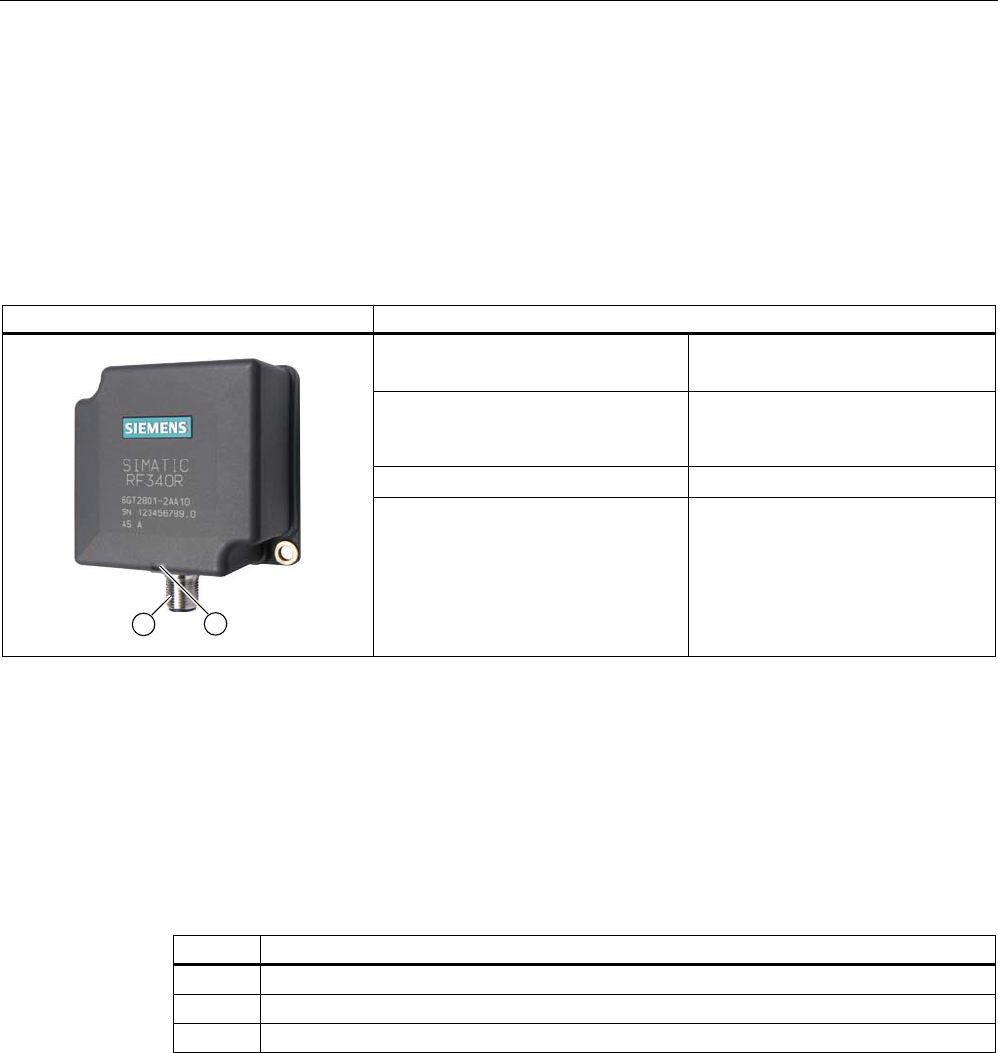
Reader RF340R Features
Design (1) RS 422 interface
(2) Operating indicator
Application Identification tasks on assembly
lines in harsh industrial
environments
Read/write distance to transponder max. 60 mm
Data transmission rate • Read: approx. 3,100 bytes/s
• Write: approx. 3,100 bytes/s
5.4.2 Display elements of the RF340R reader
Table 5-5 Display elements of the reader
Color Meaning
Green Operating voltage available
yellow Transponder present
red Errors
5.4.3 Ensuring reliable data exchange
The "center point" of the transponder must be situated within the transmission window.
Readers
5.4 RF340R
SIMATIC RF300
System Manual, Release 04/2006, J31069 D0166-U001-A2-7618 5-13
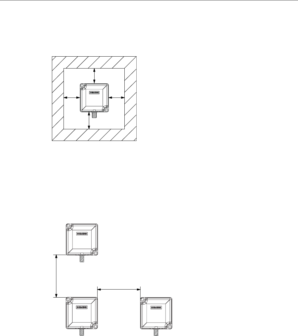
5.4.4 Metal-free area
The RF340R can be flush-mounted in metal. Please allow for a possible reduction in the field
data values.
6,0$7,&
D
D
DD
5)5
Figure 5-7 Metal-free area for RF340R
To avoid any impact on the field data, the distance a should be ≥ 20 mm.
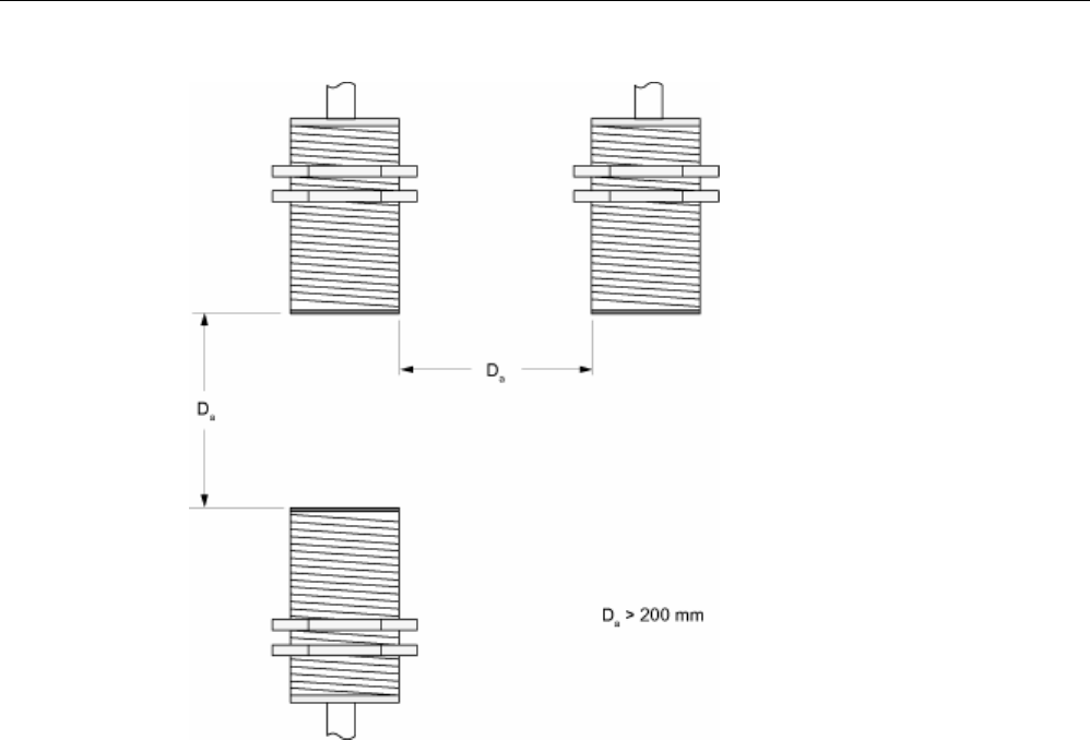
5.4.5 Minimum distance between RF340R readers
ุPP
0LQLPXPGLVWDQFHIURP5)5WR5)5
'
'
'
5)5
5)5 5)5
Figure 5-8 Minimum distance between RF340R readers

Readers
5.4 RF340R
SIMATIC RF300
5-14 System Manual, Release 04/2006, J31069 D0166-U001-A2-7618
5.4.6 Technical data of the RF340R reader
Table 5-6 Technical data of the RF340R reader
Inductive interface to the transponder
Transmission frequency for power/data
13.56 MHz
Antenna Integrated
Interface to communication module RS 422 (3964R protocol)
Baud rate 19200 baud, 57600 baud, 115200 baud
Cable length between reader and communication
module
Max. 120 m
Data cable length max. 1000 m
(shielded cable)
Read/write distances of reader See RF340R field data
Minimum distance between two RF340R readers ≥ 500 mm
Maximum data transfer rate
reader - transponder (tag)
Reading
Writing
Approx. 3100 bytes/s
Approx. 3100 bytes/s
Functions Initialize/read/write transponder
Scan status and diagnostics information
Switch antenna on/off
Repeat command
Scan transponder serial numbers
Voltage supply 24 V DC, 110 mA typ.
Display elements 2-color LED
(operating voltage, presence, error)
Plug connector M12 (8-pin)
Enclosure
Dimensions (in mm)
Color
Material
75 x 75 x 40 (without M12 device connector)
Anthracite
Plastic PA 12
Fixing 2 x M5 screws
Ambient temperature
during operations
during transport and storage
-25 °C to +70 °C
-40 °C to +85 °C
Degree of protection to EN 60529
Shock to EN 60 721-3-7 Class 7 M2
Overall shock response spectrum, Type II
Vibration to EN 60 721-3-7 Class 7 M2
IP65
50 g
1 g (9 to 200 Hz)
1.5 g (200 to 500 Hz)
Weight Approx. 250 g
MTBF (Mean Time Between Failures) in years 140,3
Approvals Radio to R&TTE guidelines EN 300 330,
EN 301489, CE, FCC

Readers
5.4 RF340R
SIMATIC RF300
System Manual, Release 04/2006, J31069 D0166-U001-A2-7618 5-15
5.4.7 FCC information
Siemens SIMATIC RF340R
FCC ID: NXW-RF340R
This device complies with Part 15 of the FCC rules. Operation is subject to the following two
conditions:
(1) This device may not cause harmful interference.
(2) This device must accept any interference received, including interference that may cause
undesired operation.
Caution
Any changes or modifications not expressly approved by the party responsible for
compliance could void the user's authority to operate the equipment.
5.4.8 Ordering data for RF340R
Product description Order No.
Reader RF340R
With RS 422 interface (3964R) for ASM 475/452/473 (S7-300,
PROFIBUS);
IP65;
-25 °C … +70 C, dimensions 75 x 91 x 41 (L x W x H in mm);
with integrated antenna;
max. limit distance 65 mm (depending on transponder)
6GT2801-2AA10
Readers
5.4 RF340R
SIMATIC RF300
5-16 System Manual, Release 04/2006, J31069 D0166-U001-A2-7618
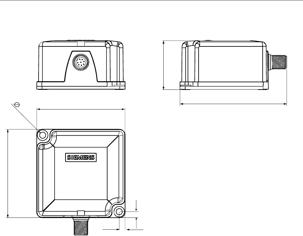
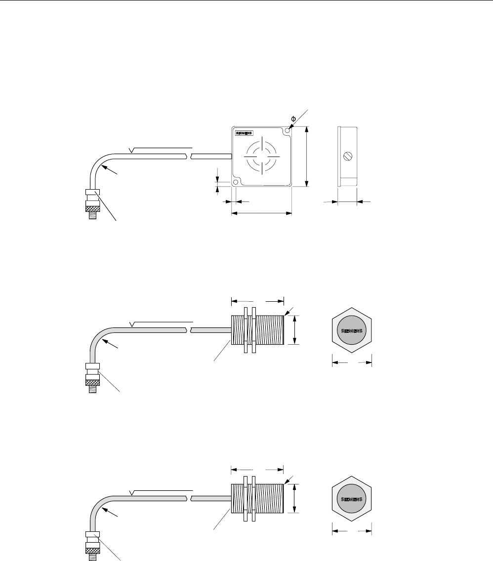
5.4.9 Dimension drawing
Figure 5-9 Dimension drawing for RF340R
Readers
5.5 RF350R
SIMATIC RF300
System Manual, Release 04/2006, J31069 D0166-U001-A2-7618 5-17
5.5 5.5 RF350R
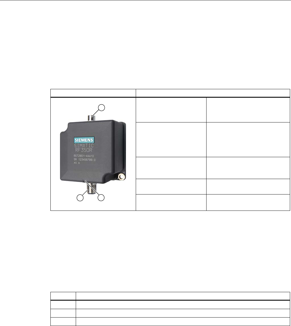
5.5.1 Features
Reader RF350R Features
Design (1) RS 422 interface
(2) Operating indicator
(3) Antenna connection
Application Identification tasks in assembly
lines in harsh industrial
environments; for external
antennas
(ANT 1, ANT 18, ANT 30)
Interfaces with which the
RF350R reader can be
operated
ASM 452, ASM 456, ASM 473,
ASM 475
Read/write distance to
transponder
max. 60 mm
Data transmission rate • Read: approx. 3,100 bytes/s
• Write: approx. 3,100 bytes/s
5.5.2 Display elements of the RF350R reader
Table 5-7 Display elements of the reader
Color Meaning
Green Operating voltage available
yellow Transponder present
red Errors
5.5.3 Ensuring reliable data exchange
The "center point" of the transponder must be situated within the transmission window.

Readers
5.5 RF350R
SIMATIC RF300
5-18 System Manual, Release 04/2006, J31069 D0166-U001-A2-7618
5.5.4 Metal-free area
The RF350R reader does not have an internal antenna. Operation is not affected by
mounting on metal or flush-mounting in metal. For information about the metal-free area
required by the external antennas, refer to the corresponding section of the chapter
Antennas
.
5.5.5 Technical data of the RF350R reader
Table 5-8 Technical data of the RF350R reader
Inductive interface to the transponder
Transmission frequency for power/data
13.56 MHz
Antenna External, plug-in MOBY E antennas ANT 1,
ANT 18 or ANT 30
Interface to communication module RS 422 (3964R protocol)
Baud rate 19200 baud, 57600 baud, 115 baud
Cable length between reader and communication
module
Max. 120 m
Data cable length max. 1000 m
(shielded cable)
Read/write distances of reader See field data
Minimum distance between two antennas See field data
Maximum data transfer rate
reader - transponder (tag)
Reading
Writing
Approx. 3100 bytes/s
Approx. 3100 bytes/s
Functions Initialize/read/write transponder
Scan status and diagnostics information
Switch antenna on/off
Repeat command
Scan transponder serial numbers
Voltage supply 24 V DC, 110 mA typ.
Display elements 2-color LED
(operating voltage, presence, error)
Plug connector M12 (8-pin); M8 (4-pin) for antenna
Enclosure
Dimensions (in mm)
Color
Material
75 x 75 x 40 (without M12 device connector)
Anthracite
Plastic PA 12
Fixing 2 x M5 screws
Ambient temperature
during operations
during transport and storage
-25 °C to +70 °C
-40 °C to +85 °C
Degree of protection to EN 60529
Shock to EN 60 721-3-7 Class 7 M2
Overall shock response spectrum, Type II
Vibration to EN 60 721-3-7 Class 7 M2
IP65
50 g
1 g (9 to 200 Hz)
1.5 g (200 to 500 Hz)
Weight Approx. 250 g
MTBF (Mean Time Between Failures) in years 140,3
Approvals Radio to R&TTE guidelines EN 300 330,
EN 301489, CE, FCC

Readers
5.5 RF350R
SIMATIC RF300
System Manual, Release 04/2006, J31069 D0166-U001-A2-7618 5-19
5.5.6 FCC information
Siemens SIMATIC RF350R
FCC ID: NXW-RF350R
This device complies with Part 15 of the FCC rules. Operation is subject to the following two
conditions:
(1) This device may not cause harmful interference.
(2) This device must accept any interference received, including interference that may cause
undesired operation.
Caution
Any changes or modifications not expressly approved by the party responsible for
compliance could void the user's authority to operate the equipment.
5.5.7 Ordering data for RF350R
Product description Order No.
Reader RF350R
With RS 422 interface (3964R) for ASM 475/452/473 (S7-300,
PROFIBUS);
IP65;
- 25 °C … +70 C, dimensions 75 x 75 x 40 (L x W x H in mm);
for plug-in antennas from the MOBY E product range;
max. limit distance 65 mm (depending on transponder)
6GT2801-4AA10
Readers
5.5 RF350R
SIMATIC RF300
5-20 System Manual, Release 04/2006, J31069 D0166-U001-A2-7618
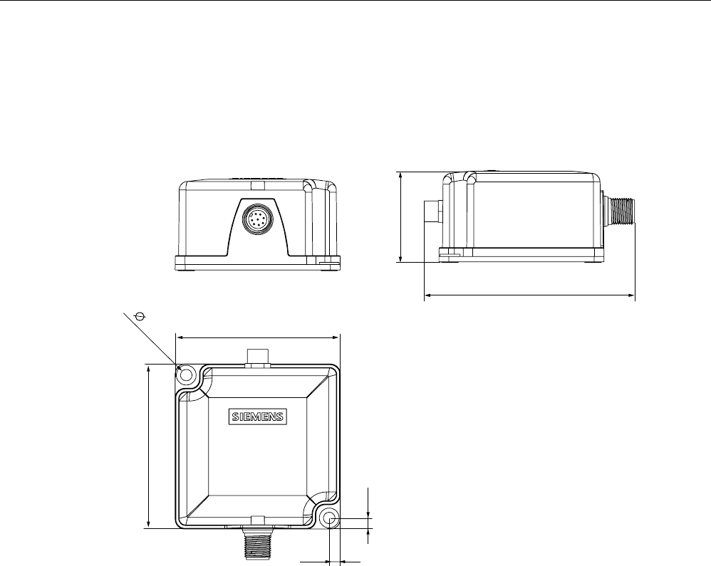
5.5.8 Dimension drawing
Figure 5-10 RF350R dimension drawing
Readers
5.5 RF350R
SIMATIC RF300
System Manual, Release 04/2006, J31069 D0166-U001-A2-7618 5-21
5.5.9 Antennas
5.5.9.1 Features
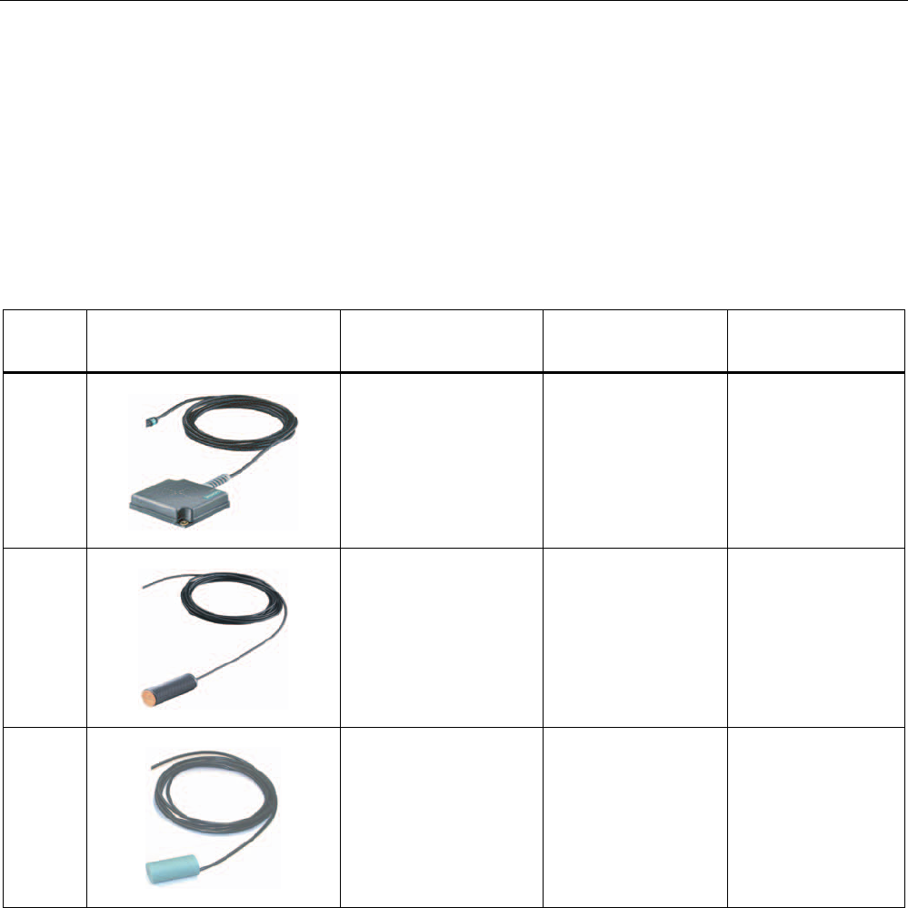
You can use the following plug-in antennas from the MOBY E product spectrum for the
RF350R reader:
Antenna Product photo Limit distance Sg
in mm 1)
Dimensions
(L x B x H)
in mm
Suitable for dynamic
operation
MOBY E
ANT 1
to 60 75 x 75 x 20 Yes
MOBY E
ANT 18
to 13 Ø M18 x 50 no
MOBY E
ANT 30
to 22 Ø M30 x 58 no
1) depending on the transponder used

Readers
5.5 RF350R
SIMATIC RF300
5-22 System Manual, Release 04/2006, J31069 D0166-U001-A2-7618
ANT 1
The ANT 1 is an antenna in the mid performance range and can be used to the customer's
advantage in production and assembly lines due to its manageable housing shape. The
antenna dimensions make it possible to read/write large quantities of data dynamically
from/to the tag during operation. The antenna cable can be connected at the reader end.
ANT 18
The ANT 18 is designed for use in small assembly lines. Due to its small, compact
construction, the antenna can be easily positioned for any application using two plastic nuts
(included in the package). The antenna cable can be connected at the reader end. With the
RF320T and RF340T tags, communication with the data storage unit is only possible in static
mode.
ANT 30
The ANT 30 is designed for use in small assembly lines. In comparison to ANT 18, the
maximum write/read distance is approximately 60 % larger. Due to its compact construction,
the antenna can be easily positioned for any application using two plastic nuts (included in
the package). The antenna cable can be connected at the reader end. With the RF320T,
RF340T and RF350T tags, communication with the data storage unit is only possible in static
mode.
Readers
5.5 RF350R
SIMATIC RF300
System Manual, Release 04/2006, J31069 D0166-U001-A2-7618 5-23
5.5.9.2 Ensuring reliable data exchange
The "center point" of the transponder must be situated within the transmission window.
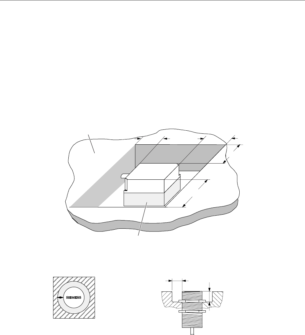
5.5.9.3 Metal-free area
The antennas ANT1, ANT18 and ANT30 can be flush-mounted on metal. Please allow for a
possible reduction in the field data values.
0HWDOIUHHDUHDIRUIOXVKPRXQWLQJ
QRWDPHWDOOLFEDVH
0HWDO
a = 40 mm
h > 20 mm
a
a
a
a
h > 20 mm
Figure 5-11 Metal-free area for ANT 1
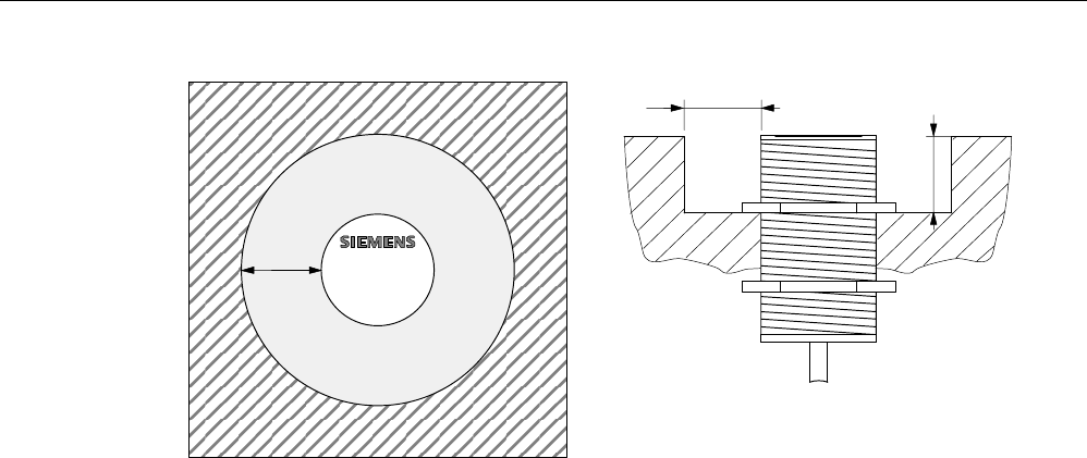
1RWH
,IWKHPHWDOIUHHDUHDLVQRW
REVHUYHGWKHOLPLWDQGRSHUDWLQJ
GLVWDQFHVDUHUHGXFHG
0HWDOIUHHDUHDIRU
IOXVKPRXQWLQJ
D
E
D PP
E PP
$17
02%<(
$17
D
Figure 5-12 Metal-free area for ANT 18
Readers
5.5 RF350R
SIMATIC RF300
5-24 System Manual, Release 04/2006, J31069 D0166-U001-A2-7618
D
E
D PP
E PP
D02%<(
$17
3ODQYLHZ
6LGHYLHZ
Figure 5-13 Metal-free area for ANT 30
Readers
5.5 RF350R
SIMATIC RF300
System Manual, Release 04/2006, J31069 D0166-U001-A2-7618 5-25
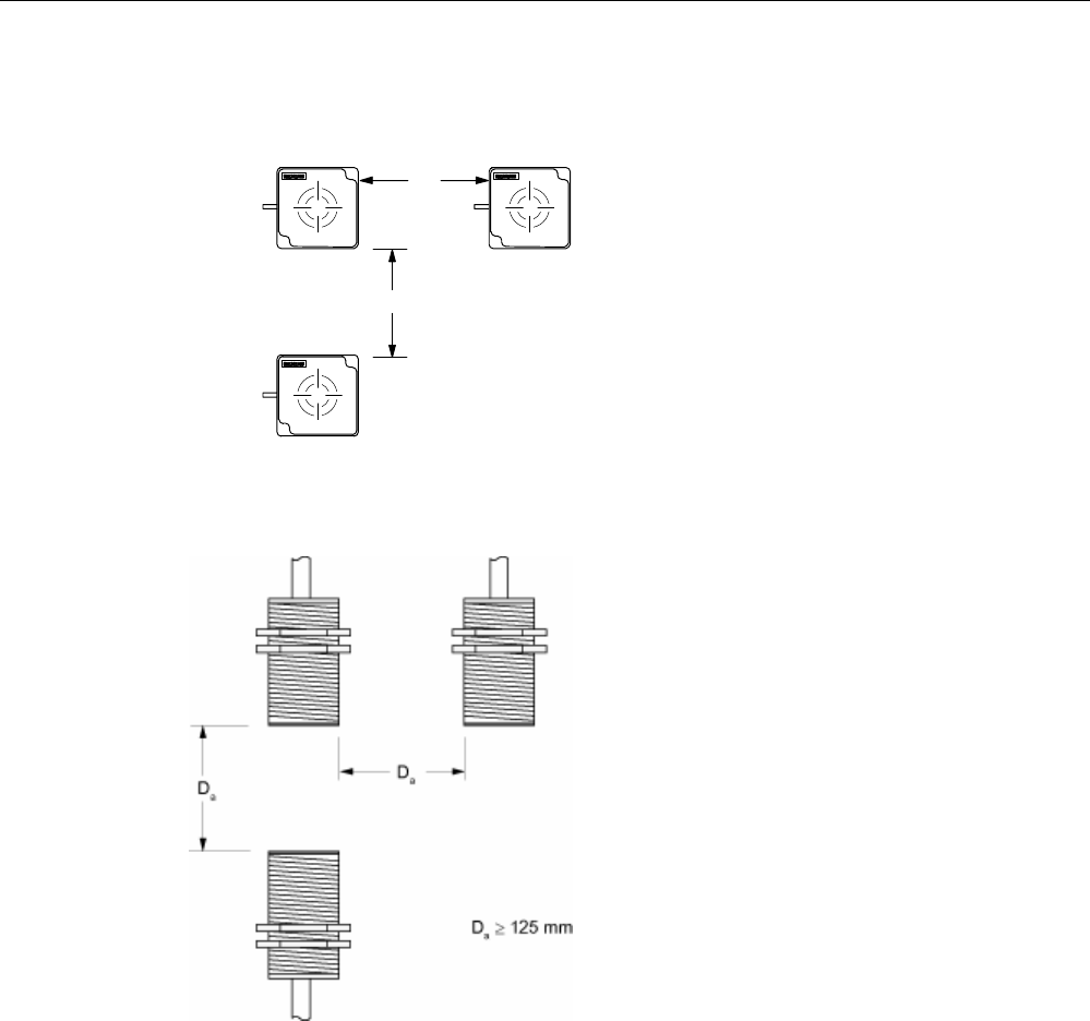
5.5.9.4 Minimum distance between antennas
7KHUHDGHUHOHFWURQLFVFDQEH
PRXQWHGGLUHFWO\DORQJVLGHHDFKRWKHU
$
17
E
'PP
D!
B
$17
$17
'PP
!
B
'
D
E
'
Figure 5-14 Minimum distance for ANT 1
Figure 5-15 Minimum distance for ANT 18
Readers
5.5 RF350R
SIMATIC RF300
5-26 System Manual, Release 04/2006, J31069 D0166-U001-A2-7618
Figure 5-16 Minimum distance for ANT 30

Readers
5.5 RF350R
SIMATIC RF300
System Manual, Release 04/2006, J31069 D0166-U001-A2-7618 5-27
5.5.9.5 Technical data for antennas
Table 5-9 Technical data for antennas ANT1, ANT18 and ANT30
Antenna ANT1 ANT18 ANT30
Read/write distance
antenna to transponder (Sg) max
100 mm 15 mm 24 mm
Enclosure dimensions in mm 75 x 75 x 20
(L x W x H)
M18 x 1.0 x 55
(Ø x thread x L)
M30 x 1.5 x 58
(Ø x thread x L)
Color Anthracite Pale turquoise
Material Plastic PA 12 Plastic Krastin
Plug connection 4-pin (pins on antenna side)
Antenna cable lengths 3 m
Type of protection to EN 60529 IP 67 IP 67 (at the front)
Shock-resistant acc. to
EN 60721-3-7, Class 7M2
Vibration-resistant to
EN 60721-3-7, Class 7M2
50 g 1)
20 g ( 3 to 500 Hz) 1)
Attachment of the antenna 2 x M5 screws 2 plastic nuts M18 x
1.0
2 plastic nuts M30 x
1.5
Ambient temperature
• During operation
• Transport and storage
• -25 °C to +70 °C
• -40 °C to +85 °C
MTBF (at +40 °C) 2,5 x 10⁵ hours
Approx. weight 80 g 120 g 150 g
1) Warning: The values for shock and vibration are maximum values and must not be applied
continuously.
5.5.9.6 Ordering data for antennas
Product description Order No.
MOBY E, ANT 1 6GT2398-1CB00
MOBY E, ANT 18 6GT2398-1CA00
MOBY E, ANT 30 6GT2398-1CD00
Readers
5.5 RF350R
SIMATIC RF300
5-28 System Manual, Release 04/2006, J31069 D0166-U001-A2-7618
5.5.9.7 Dimension drawings for antennas
&DEOHOHQJWKP
0LQLPXPEHQGLQJ
UDGLXV
$17FDQEHFRQQHFWHG
DWUHDGHUHQG
20 mm
Figure 5-17 Dimension drawing for ANT 1
&DEOHOHQJWKP
0LQLPXPEHQGLQJ
UDGLXV
$17FDQEHFRQQHFWHG
DWUHDGHUHQG
$QWHQQDKHDG
6LGHYLHZRI
DQWHQQDKHDG
$QWHQQDHQG
)LQHWKUHDGSLWFK
PP
0
02%<(
$17
Figure 5-18 Dimension drawing for ANT 18
&DEOHOHQJWKP
0LQLPXPEHQGLQJ
UDGLXV
$17FDQEHFRQQHFWHG
DWUHDGHUHQG
$QWHQQDKHDG
6LGHYLHZRI
DQWHQQDKHDG
$QWHQQDHQG
)LQHWKUHDGSLWFK
PP
0
$17
02%<(
Figure 5-19 Dimension drawing for ANT 30
SIMATIC RF300
System Manual, Release 04/2006, J31069 D0166-U001-A2-7618 6-1
Transponders 6
6.1 6.1 Overview
Transponders consist predominantly of logic, FRAM and/or EEPROM.
If a transponder moves into the transmission window of the reader, the necessary power for
all of the circuit components is generated and monitored by the power supply unit. The
pulse-coded information is prepared in such a way that it can be processed further as pure
digital signals. The handling of data, including check routines, is performed by the logic,
which also manages the various memories.
6.2 6.2 RF320T
6.2.1 Features
Transponder RF320T Features
Application Identification tasks on small assembly lines
in harsh industrial environments
Memory Read-only area (4 bytes UID)
User data area (20 bytes)
Read/write range See section
Field data
Mounting on metal Not possible Recommended distance from
metal ≥ 20 mm
Transponders
6.2 RF320T
SIMATIC RF300
6-2 System Manual, Release 04/2006, J31069 D0166-U001-A2-7618
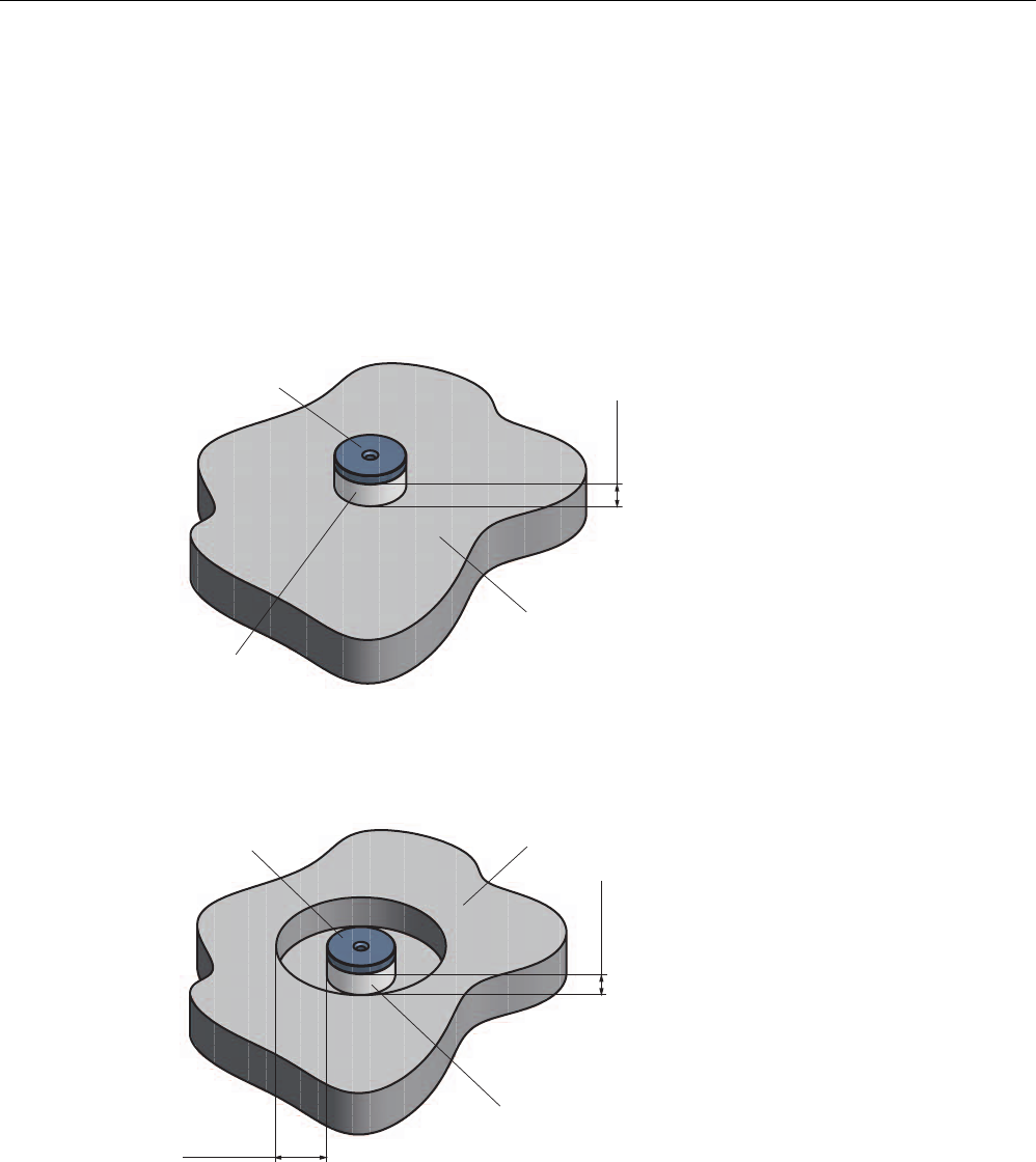
6.2.2 Metal-free area
Mounting of RF320T on metal
Direct mounting of the RF320T on metal is not allowed.
The following figures show the minimum distance between the RF320T and metal:
1RQPHWDO
0HWDO
K!PP
'DWDPHPRU\
Figure 6-1 Mounting of an RF320T on metal with spacer
Flush-mounting of RF320T in metal
D!PP
K!PP
'DWDPHPRU\ 0HWDO
1RQPHWDO
Figure 6-2 Flush-mounting of RF320T in metal with spacer
At lower values, the field data change significantly, resulting in a reduced range.

Transponders
6.2 RF320T
SIMATIC RF300
System Manual, Release 04/2006, J31069 D0166-U001-A2-7618 6-3
6.2.3 Technical data
Table 6-1 Technical data for RF320T
Memory size 20 bytes EEPROM (r/w), 4 bytes UID (ro)
Memory organization Byte-oriented access, write protection possible
in 4-byte blocks
MTBF (Mean Time Between Failures) in years 1871
Read cycles Unlimited
Write cycles, min. 50 000
at ≤ 40 °C, typical > 100 000
Data retention time > 10 years (at < +40 °C)
Read/write distance max. 18 mm (see field data)
Energy source Inductive power transmission
Shock/vibration-resistant to EN 60721-3-7, Class 7
M3
100 g/20 g
Torsion and bending load not permissible
Fixing Adhesive/M3 screws
Recommended spacing from metal > 20 mm
Degree of protection per EN 60529 • IP67/IPX9K
Housing
• Dimensions
• Color/material
Button
• Ø 27 mm x 4 mm
• Black/epoxy resin
Ambient temperature
• During operation
• Storage and transport
• -25 to +85 °C
• -40 to +125 °C
Weight Approx. 5 g
Note
All the technical data listed are typical data and are applicable for an ambient temperature of
between 0 C and +50°C and a metal-free environment.
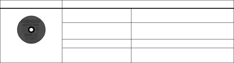
6.2.4 Ordering data
Transponder RF320T Order number:
Transponder RF320T, button, 20 byte EEPROM,
IP 67, -25 °C to +85 °C, d = 27 mm x 4 mm
6GT2800-1CA00

Transponders
6.2 RF320T
SIMATIC RF300
6-4 System Manual, Release 04/2006, J31069 D0166-U001-A2-7618
6.2.5 Dimension drawing
Dimensions of the device
Dimensions in millimeters
Transponders
6.3 RF340T
SIMATIC RF300
System Manual, Release 04/2006, J31069 D0166-U001-A2-7618 6-5
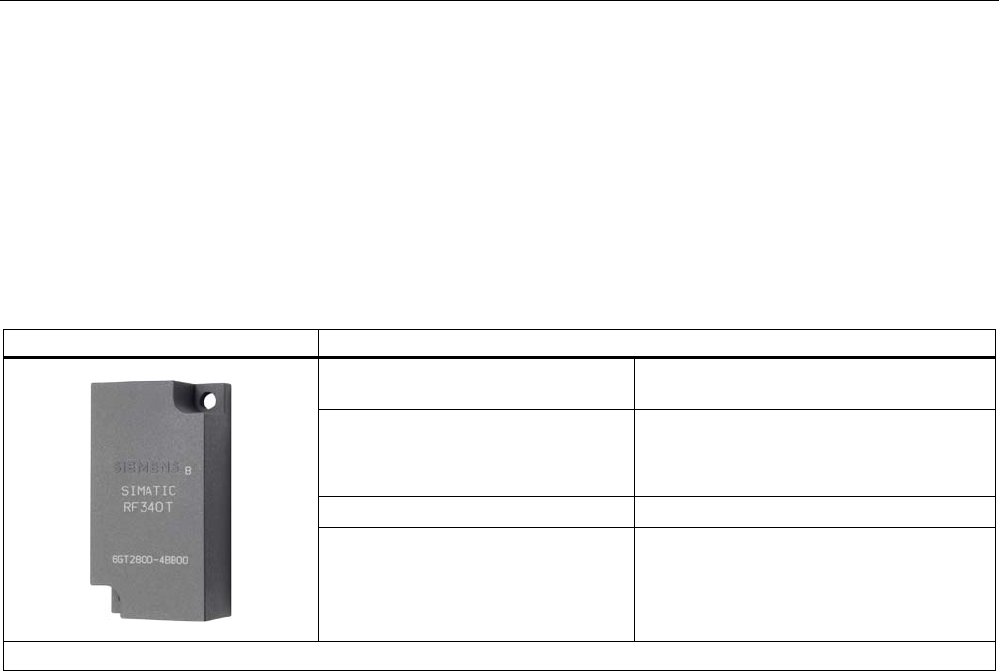
6.3 6.3 RF340T
6.3.1 Features
Transponder RF340T Features
Application Identification tasks on small assembly lines
in harsh industrial environments
Memory Read-only area (4 bytes UID)
Read/write memory (8 KB)
OTP 1) memory (20 bytes)
Read/write range See section
Field data
Mounting on metal Direct mounting on metal is possible.
1) OTP: (One Time Programmable)
Transponders
6.3 RF340T
SIMATIC RF300
6-6 System Manual, Release 04/2006, J31069 D0166-U001-A2-7618
6.3.2 Metal-free area
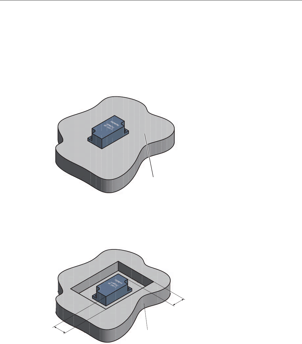
Direct mounting of the RF340T on metal is permitted.
Mounting of RF340T on metal
0HWDO
Figure 6-3 Mounting of RF340T on metal
Flush-mounting of RF340T in metal:
D
D
0HWDO
Figure 6-4 Flush-mounting of RF340T in metal
The standard value for a is ≥ 20 mm. At lower values, the field data change significantly,
resulting in a reduction in the range.

Transponders
6.3 RF340T
SIMATIC RF300
System Manual, Release 04/2006, J31069 D0166-U001-A2-7618 6-7
6.3.3 Technical data
Table 6-2 Technical data for RF340T
Memory size 8 KB
Memory organization Blocks of 8 bits / 1 byte
Memory configuration
• Serial number (UID)
• Application memory
• OPT memory
• 4-byte (fixed code)
• 8189 bytes r/w
• 20-byte OTP 1) memory
Storage technology FRAM / EEPROM
MTBF (Mean Time Between Failures) in years 1201
Write cycles, at +40°C Virtually unlimited (>1010)
Read cycles Unlimited
Transmission rate
• Read
• Write
with RS 422 reader:
Approx. 0.3 ms / byte
approx. 0.3 ms / byte
with IQ-Sense reader:
Approx. 20 ms / byte
approx. 25 ms / byte
Data retention > 10 years
Read/write distance 0 to max. 60 mm (depends on reader used)
Multitag capability max. 4 transponders
Recommended spacing from metal can be directly mounted on metal
Power supply Inductive, without battery
Degree of protection to EN 60529
Shock to EN 60721-3-7
Vibration to EN 60721-3-7
Torsion and bending load
IP68/IPX9K
50 g
20 g
Not permitted permanently
Housing dimensions
Color
Material
Fixing
48 x 25 x 15 mm (L x W x H)
Anthracite
PA12
2 screws (M3)
Ambient temperature
• During operation
• Storage and transport
-25°C to +85°C
-40°C to +85°C
Weight Approx. 25 g
1) OTP: (One Time Programmable)
6.3.4 Ordering data
Transponder RF340T Order number:
Transponder RF340T, 8 KB FRAM, IP 68, -25 °C
to +85 °C, 48 x 25 x 15 mm (L x W x H)
6GT2800-4BB00
Transponders
6.3 RF340T
SIMATIC RF300
6-8 System Manual, Release 04/2006, J31069 D0166-U001-A2-7618
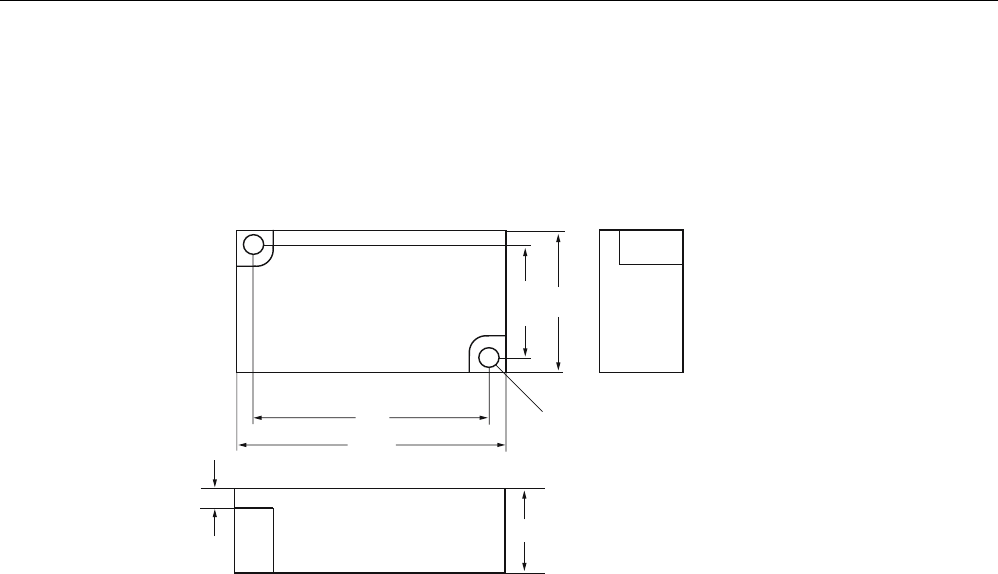
6.3.5 Dimension drawing
Dimensions of the device
6,(0(16
6,0$7,&
5)7
Dimensions in millimeters
Transponders
6.4 RF350T
SIMATIC RF300
System Manual, Release 04/2006, J31069 D0166-U001-A2-7618 6-9
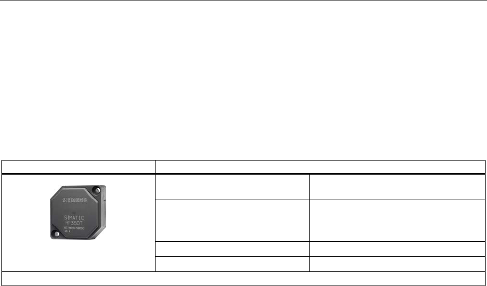
6.4 6.4 RF350T
6.4.1 Features
Transponder RF350T Features
Application Identification tasks on small assembly lines
in harsh industrial environments
Memory Read-only area (4 bytes UID)
Read/write memory (32 KB)
OTP 1) memory (20 bytes)
Read/write range See section
Field data
Mounting on metal Direct mounting on metal is possible.
1) OTP: (One Time Programmable)
Transponders
6.4 RF350T
SIMATIC RF300
6-10 System Manual, Release 04/2006, J31069 D0166-U001-A2-7618
6.4.2 Metal-free area
Direct mounting of the RF350T on metal is permitted.
Mounting of RF350T on metal
Figure 6-5 Mounting of RF350T on metal
Flush-mounting of RF350T in metal:
Figure 6-6 RF350T flush-mounted in metal
The standard value for a is ≥ 20 mm. At lower values, the field data change significantly,
resulting in a reduction in the range.

Transponders
6.4 RF350T
SIMATIC RF300
System Manual, Release 04/2006, J31069 D0166-U001-A2-7618 6-11
6.4.3 Technical data
Table 6-3 Technical data for RF350T
Memory size 32 KB
Memory organization Blocks of 8 bits / 1 byte
Memory configuration
• Serial number (UID)
• Application memory
• OTP 1) memory
• 4-byte (fixed code)
• 32765 bytes r/w
• 20 bytes
Storage technology FRAM / EEPROM
MTBF (Mean Time Between Failures) in years 1201
Write cycles, at +40°C Virtually unlimited (>1010)
Read cycles Practically unlimited (>1010)
Transmission rate
• read
• Write
with RS 422 reader:
Approx. 0.3 ms / byte
approx. 0.3 ms / byte
with IQ-Sense reader:
Approx. 20 ms / byte
approx. 25 ms / byte
Data retention > 10 years
Read/write distance 0 to max. 60 mm (depends on reader used)
Multitag capability max. 4 transponders
Recommended spacing from metal can be directly mounted on metal
Power supply Inductive, without battery
Degree of protection to EN 60529
Shock to EN 60721-3-7
Vibration to EN 60721-3-7
Torsion and bending load
IP68
50 g
20 g
Not permitted permanently
Housing dimensions
Color
Material
Fixing
50 x 50 x 20 mm (L x W x H)
Anthracite
PA12
2 screws M4
Ambient temperature
• During operation
• Storage and transport
-25°C to +85°C
-40°C to +85°C
Weight Approx. 25 g
1) OTP: (One Time Programmable)
6.4.4 Ordering data
RF350T Order number:
32 KB FRAM (read/write) + 4 byte EEPROM
(read only), IP 68, -25 °C to +85 °C, dimensions
50 x 50 x 20 (LxWxH in mm)
6GT2800-5BD00
Transponders
6.4 RF350T
SIMATIC RF300
6-12 System Manual, Release 04/2006, J31069 D0166-U001-A2-7618
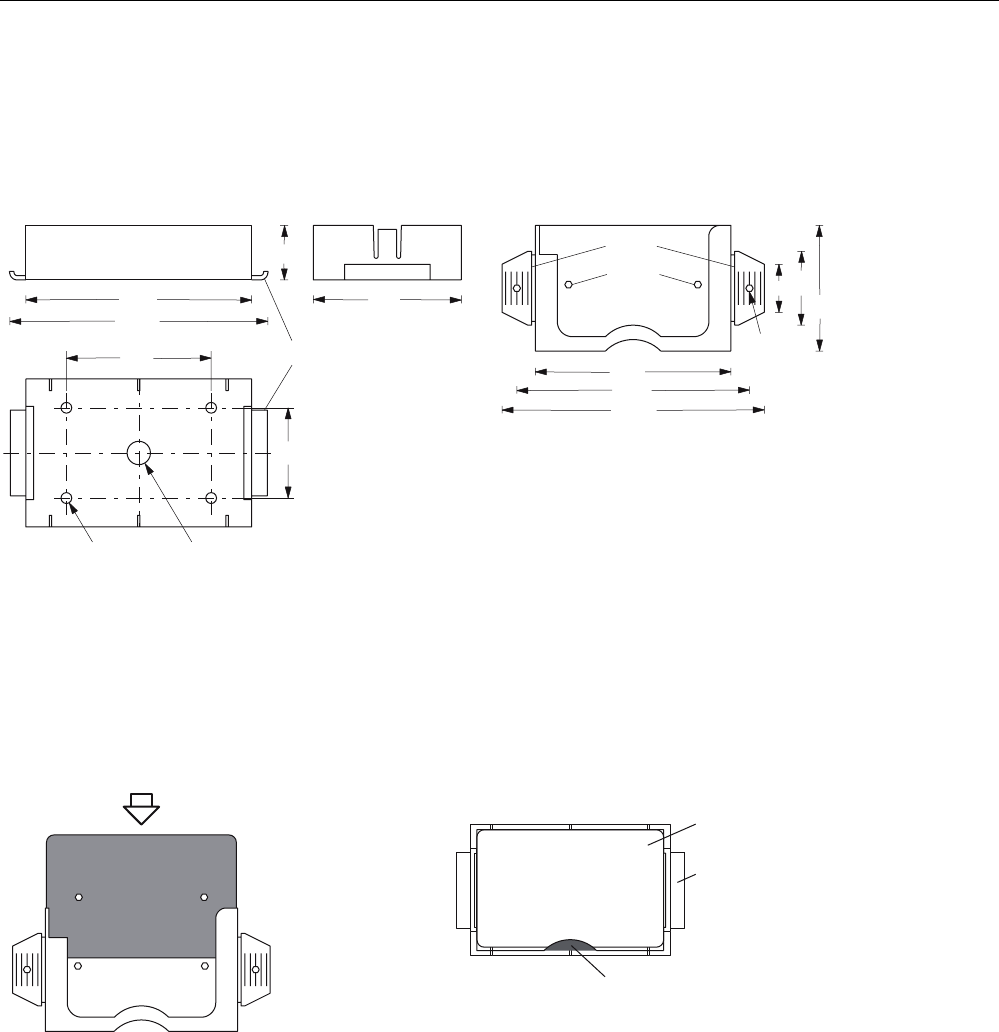
6.4.5 Dimension drawing
Dimension drawing of RF350T transponder
7KHWUDQVSRQGHUFDQEHPRXQWHGDVVKRZQZLWK
WKHIL[LQJIUDPH
,QVWDOODWLRQGLDJUDP
)L[LQJIUDPH
7UDQVSRQGHU
Figure 6-7 RF350T dimension drawing
Transponders
6.5 RF360T
SIMATIC RF300
System Manual, Release 04/2006, J31069 D0166-U001-A2-7618 6-13
6.5 6.5 RF360T
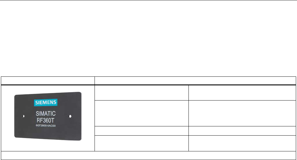
6.5.1 Features
Transponder RF360T Features
Application Identification tasks on small assembly lines
in harsh industrial environments
Memory Read-only area (4 bytes UID)
Read/write memory (8 KB)
OTP 1) memory (20 bytes)
Read/write range See section
Field data
Mounting on metal Not possible; recommended distance from
metal ≥ 20 mm
1) OTP. (One Time Programmable)
Transponders
6.5 RF360T
SIMATIC RF300
6-14 System Manual, Release 04/2006, J31069 D0166-U001-A2-7618
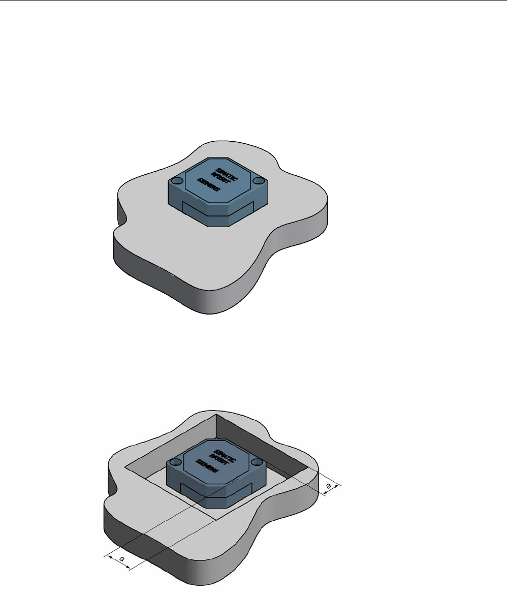
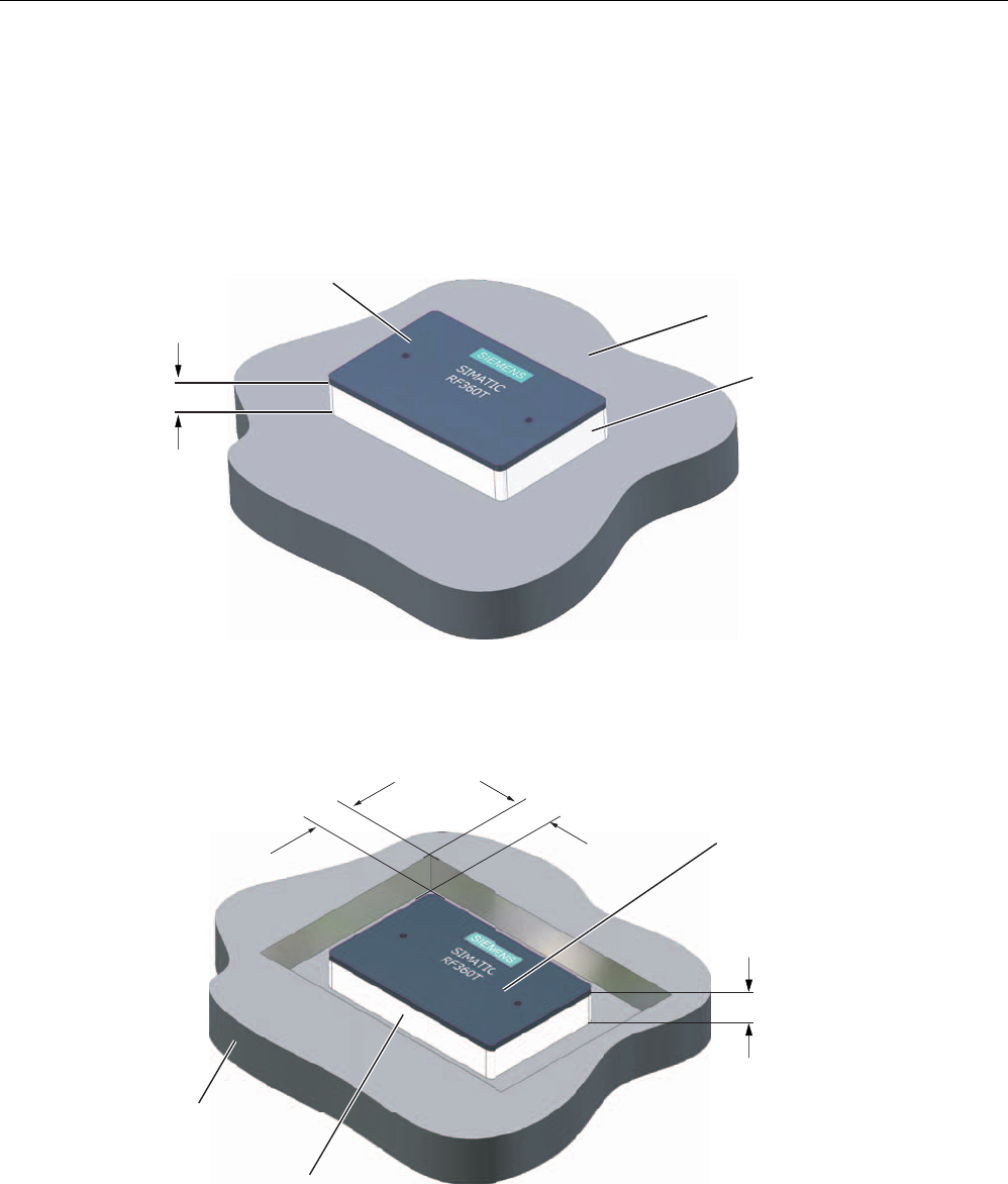
6.5.2 Metal-free area
Direct mounting of the RF360T on metal is not allowed. A distance ≥ 20 mm is
recommended. This can be achieved using the spacer 6GT2190-0AA00 in combination with
the fixing pocket 6GT2190-0AB00.
Mounting of RF360T on metal
K
0HWDO
1RQPHWDO
'DWDVWRUDJHXQLW
Figure 6-8 Mounting of RF360T with spacer
The standard value for h is ≥ 20 mm.
Flush-mounting of RF360T in metal:
1RQPHWDO
0HWDO
D
D
'DWDVWRUDJHXQLW
K
Figure 6-9 Flush-mounting of RF360T with spacer
The standard value for a is ≥ 20 mm. At lower values, the field data change significantly,
resulting in a reduction in the range.
Transponders
6.5 RF360T
SIMATIC RF300
System Manual, Release 04/2006, J31069 D0166-U001-A2-7618 6-15
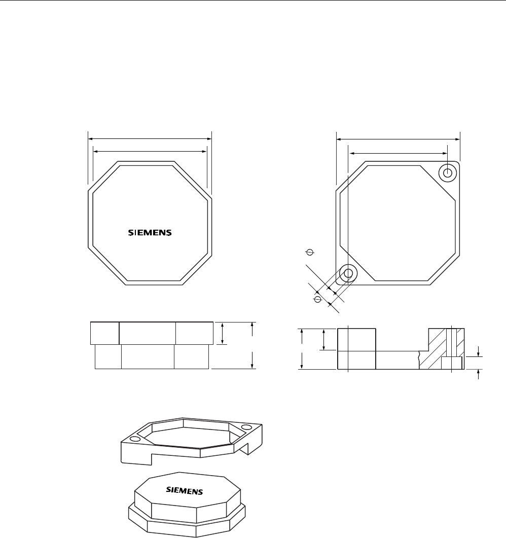
Dimensions of spacer and fixing pocket for RF360T
+ROGLQJFOLS
7KHVSDFHUFDQEHGLUHFWO\PRXQWHGRQPHWDO,QFRPELQDWLRQZLWKWKH
IL[LQJSRFNHWDQRQPHWDOGLVWDQFHRIPPUHVXOWVEHWZHHQWKHWUDQVSRQGHUDQGPHWDO
0RXQWLQJ
:LWKRUVFUHZV0
:LWKUXEEHUVRQWKHKROGLQJFOLSVHJRQPHVKER[HV
:LWKFDEOHWLHVRQWKHKROGLQJFOLSVHJRQPHVKER[HV
(DUV
+ROGLQJNQREV
'LPHQVLRQVNHWFK
6SDFHU*7$$ )L[LQJSRFNHW*7$%
7KHIL[LQJSRFNHWLVDWWDFKHGWRDQRQPHWDO
EDVHE\WKHHDUV7KLVFDQEHDFKLHYHG
ZLWK
6FUHZVLQWKHKROHVSURYLGHG
5LYHWVLQWKHKROHVSURYLGHG
1DLOVWKURXJKWKHKROHV
7DFNVWKURXJKWKHSODVWLFRIWKHHDUV
3XVKLQJLQWRWKHVSDFHUV
7KHHDUVFDQEHPRYHGWKURXJKXSWRr
7KHWUDQVSRQ
GHULV
LQVHUWHGLQWR
WKH
IL[LQJSRFNHW
/RFNLQJLVYLD
WKHKROGLQJ
NQREVLQWKH
IL[LQJSRFNHW 'DWDPHPRU\
6SDFHU
)L[LQJSRFNHW
7KHWUDQVSRQGHULVLQVHUWHGLQWRWKH
IL[LQJSRFNHW7KHHDUVDUHPRYHGE\
rDQGLQVHUWHGLQWRWKHVSDFHU7KH
IL[LQJSRFNHWPXVWEH
DOLJQHGVXFKWKDWLWFRYHUV
WKHWUDQVSRQGHUVHH)LJXUH/RFNLQJ
LVDXWRPDWLF
7UDQVSRQGHUZLWKIL[LQJSRFNHW 7UDQVSRQGHUZLWKIL[LQJSRFNHWDQG
VSDFHUFRQQHFWHGWRJHWKHU
0DWHULDO3$
5HDVVHPEO\LQVWUXFWLRQV
6,(0(16
Figure 6-10 Dimensions of spacer and fixing pocket for RF360T

Transponders
6.5 RF360T
SIMATIC RF300
6-16 System Manual, Release 04/2006, J31069 D0166-U001-A2-7618
6.5.3 Technical data
Table 6-4 Technical data for RF360T
Memory size 8 KB
Memory organization Blocks of 8 bits / 1 byte
Memory configuration
• Serial number (UID)
• Application memory
• OTP 1) memory
• 4-byte (fixed code)
• 8189 bytes r/w
• 20 bytes
Storage technology FRAM / EEPROM
MTBF (Mean Time Between Failures) in years 1201
Write cycles, at +40°C Virtually unlimited (>1010)
Read cycles Practically unlimited (>1010)
Transmission rate
• Read
• Write
with RS 422 reader:
Approx. 0.3 ms / byte
approx. 0.3 ms / byte
with IQ-Sense reader:
Approx. 20 ms / byte
approx. 25 ms / byte
Data retention > 10 years
Read/write distance 0 to max. 60 mm (depends on reader used)
Multitag capability max. 4 transponders
Recommended spacing from metal ≥ 20 mm; e.g. using spacer 6GT2190-0AA00 in
conjunction with fixing pocket 6GT2190-0AB00
Power supply Inductive, without battery
Degree of protection to EN 60529
Shock to EN 60721-3-7
Vibration to EN 60721-3-7
Torsion and bending load
IP67
50 g
20 g
Not permitted permanently
Housing dimensions
Color
Material
Fixing
85.8 x 54.8 x 2.5 mm (L x W x H)
Anthracite
PA12
2 screws (M3) or with fixing pocket 6GT2190-
0AB00
Ambient temperature
• During operation
• Storage and transport
-25°C to +75°C
-40°C to +85°C
Weight Approx. 25 g
1) OTP: (One Time Programmable)
6.5.4 Ordering data
RF360T Order number
8 KB FRAM (read/write) + 4 byte EEPROM (read
only), IP 67, -25 °C to +75 °C, dimensions 85.8 x
54.8 x 2.5 (LxWxH in mm)
6GT2800-4AC00
Transponders
6.5 RF360T
SIMATIC RF300
System Manual, Release 04/2006, J31069 D0166-U001-A2-7618 6-17
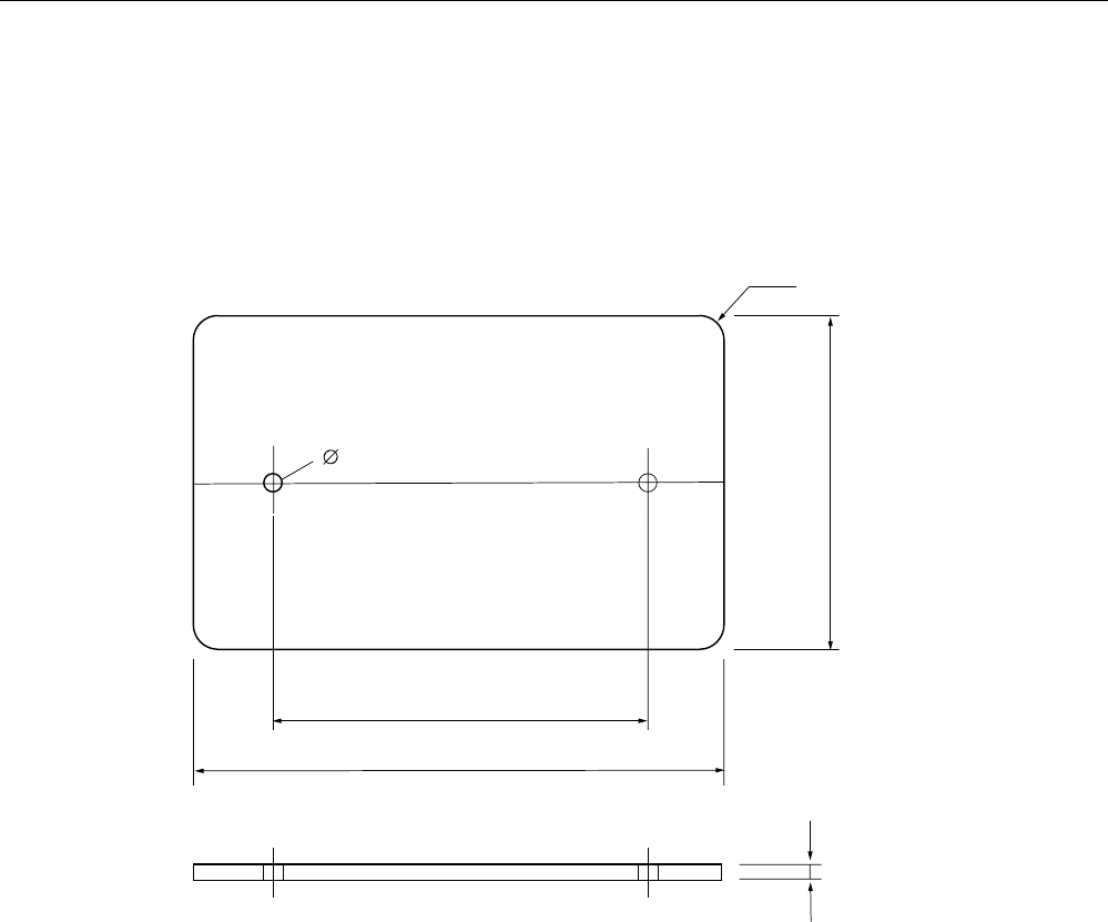
6.5.5 Dimension drawing
Dimension drawing of RF360T transponder
5
Figure 6-11 Dimensions of RF360T
Transponders
6.6 Memory configuration of the RF300 tags
SIMATIC RF300
6-18 System Manual, Release 04/2006, J31069 D0166-U001-A2-7618
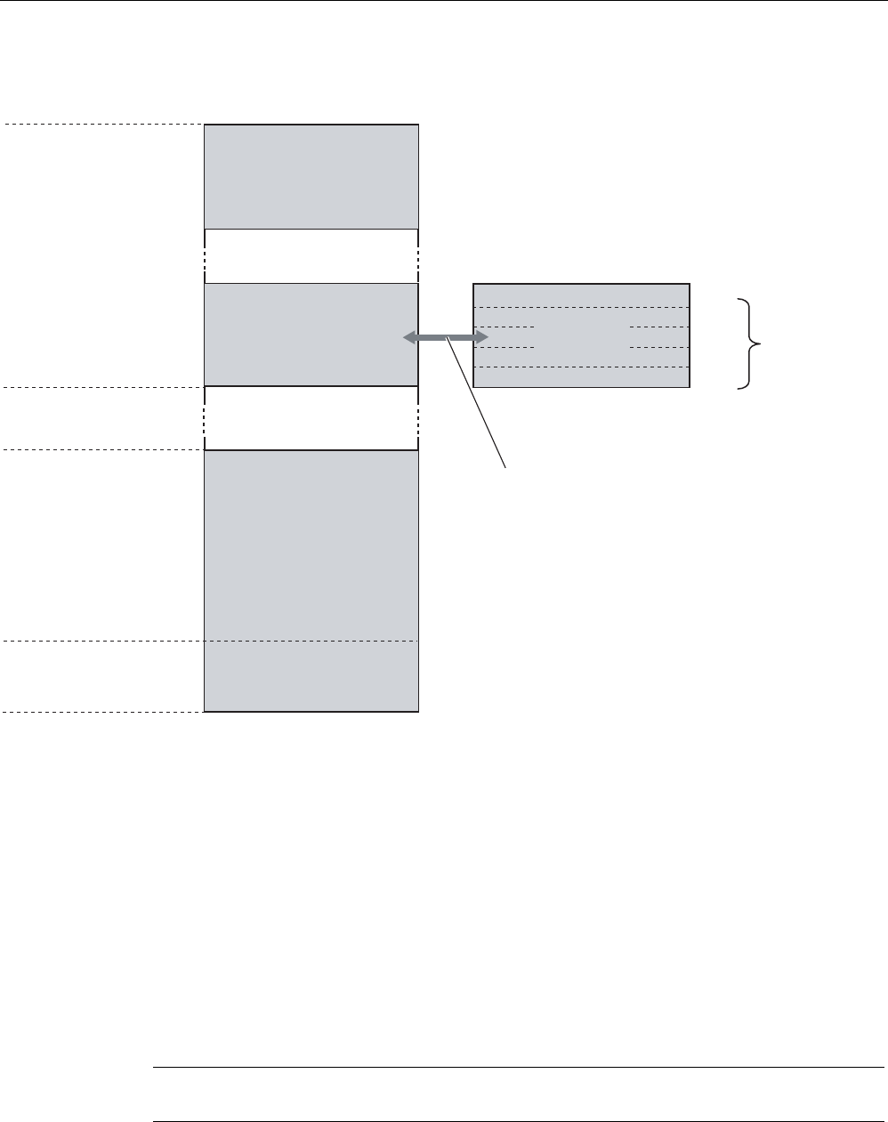
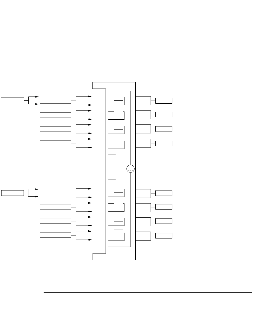
6.6 6.6 Memory configuration of the RF300 tags
5)7
5)7
5)7
5)7
E\WHV
8,'UHDGRQO\
E\WHV
8VHUDUHD
UHDGZULWH
)5$0
8VHUDUHD
UHDGZULWH
((3520
.
.
273
QRWZLWK
,46HQVH
)))
)))
))
))
))&
))&
))
))&
))
))
))
3K\VLFDOO\LGHQWLFDOPHPRU\
:KHQWKH273DUHDLVXVHGWKH
FRUUHVSRQGLQJXVHUDUHD))
))FDQQRORQJHUEHPRGLILHG
UHDGRQO\
PD[
EORFNVRI
E\WHVHDFK
5)7
5)7
5)7
Figure 6-12 Memory configuration of the RF300 tags
The memory configuration of an RF300 tag always comprises an EEPROM memory that has
20 bytes for user data (read/write) and a 4 byte unique serial number (UID, read only). For
reasons of standardization, the UID is transferred as an 8 byte value through a read
command to address FFF0 with a length of 8. The unused 4 high bytes are filled with zeros.
A high-speed FRAM memory (read/write) is available as an option. Depending on the tag
type, this is 8 KB (0-1FFC) or 32 KB (0-7FFC) in size.
The EEPROM memory area (address FF00-FF13) can also be used as a so-called "OTP"
memory (One Time Programmable). The 5 block addresses FF80, FF84, FF88, FF8C and
FF90 are used for this purpose. A write command to this block address with a valid length (4,
8, 12, 16, 20 depending on the block address) protects the written data from subsequent
overwriting.
Notice
This operation is not reversible.

Transponders
6.6 Memory configuration of the RF300 tags
SIMATIC RF300
System Manual, Release 04/2006, J31069 D0166-U001-A2-7618 6-19
Note
The OTP area cannot be used for the IQ-Sense reader variant.
When the OTP area is used, it must also be ensured that the blocks are write-protected
starting from Block 0consecutively.
Examples:
3 blocks (with write command), Block 0, 1, 2 (FF80, length = 12): valid
2 blocks (consecutive), Block 0 (FF80, length =4), Block 1 (FF84, length = 4): valid
2 blocks (consecutive), Block 0 (FF80, length =4), Block 2 (FF88, length = 4): Invalid
1 Block, Block 4 (FF90, length = 4): Invalid
The EEPROM user memory (address FF00-FF13, or FF80-FF90) requires significantly more
time for writing (approx. 11 ms/byte) than the high-speed FRAM memory. For time-critical
applications with a write function, it is therefore recommended that FRAM tags are used (e.g.
RF340T, RF350T, RF360T).

Transponders
6.6 Memory configuration of the RF300 tags
SIMATIC RF300
6-20 System Manual, Release 04/2006, J31069 D0166-U001-A2-7618
SIMATIC RF300
System Manual, Release 04/2006, J31069 D0166-U001-A2-7618 7-1
Communication modules 7
7.1 7.1 8xIQ-Sense
7.1.1 Features
Field of application
The 8xIQ-Sense module is the link between the RF310R with 8xIQ-Sense interface and
SIEMENS S7-300 and functions in the same manner as the communication module
(interface module). It can be operated centrally in an S7-300 or decentrally in an ET200M.
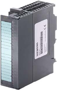
Figure 7-1 8xIQ-Sense interface module
Communication modules
7.1 8xIQ-Sense
SIMATIC RF300
7-2 System Manual, Release 04/2006, J31069 D0166-U001-A2-7618
7.1.2 Indicators
Status displays
The 8xIQ-Sense module has the following LEDs:
A green LED, which has no function for RFID devices, and a red SF LED (system fault LED),
which indicates the diagnostic state of the module.
LEDs Labeling LED
status
Meaning
Green
LED per
channel
0…7 Has no function here
Illuminate
d
Module fault, sensor fault,
active teach-in operation,
external auxiliary voltage
missing
6)
60
[,46HQVH
;)$%
;
Red SF
Not
illuminate
d
No fault or no active teach-in
operation
Communication modules
7.1 8xIQ-Sense
SIMATIC RF300
System Manual, Release 04/2006, J31069 D0166-U001-A2-7618 7-3
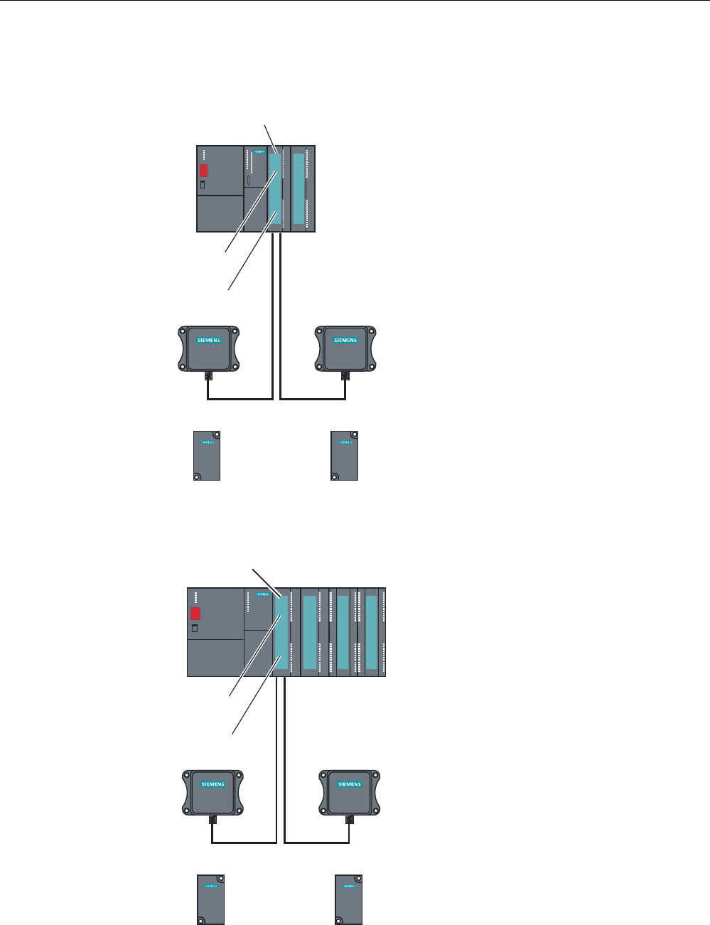
7.1.3 Configuration
Centralized configuration with SIMATIC S7-300
6,0$7,&
5)5
6,0$7,&
5)5
6,0$7,&
5)7
6,0$7,&
5)7
2WKHUPRGXOHVIURPWKH6UDQJH
LQFOXGLQJ[,46HQVH
$60FKDQQHO
5HDGHUZLWK[,46HQVH
LQWHUIDFH
5HDGHU5HDGHU
7UDQVSRQGHU7UDQVSRQGHU
[,46HQVH
6
Figure 7-2 RF310R reader with 8xIQ-Sense interface
Distributed configuration with ET 200M
6,0$7,&
5)5
6,0$7,&
5)5
6,0$7,&
5)7
6,0$7,&
5)7
2WKHUPRGXOHVIURPWKH6UDQJH
LQFOXGLQJ[,46HQVH
$60FKDQQHO
5HDGHUZLWK[,46HQVH
LQWHUIDFH
5HDGHU5HDGHU
7UDQVSRQGHU7UDQVSRQGHU
[,46HQVH
(70
Figure 7-3 RF310R reader with 8xIQ-Sense interface
Communication modules
7.1 8xIQ-Sense
SIMATIC RF300
7-4 System Manual, Release 04/2006, J31069 D0166-U001-A2-7618
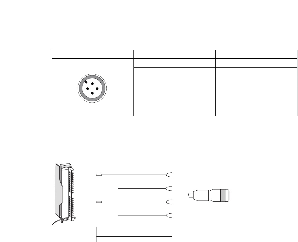
Pin assignment of RF310R with IQ-Sense interface
Table 7-1 Pin assignment of RF310R with IQ-Sense interface
Pin Pin, device end, 4-pin M12 Assignment
1 IQ-Sense
2 Not assigned
3 IQ-Sense
4 Not assigned
Configuration of connecting cable from 8xIQ-Sense to RF310R
PD[P
6/*FRQQHFWRU
0VRFNHW
5HDGHUVLGH
,46HQVHVLGH
EURZQ
EOXH
Figure 7-4 Cable and pin assignment of RF300 with IQ-Sense

Communication modules
7.1 8xIQ-Sense
SIMATIC RF300
System Manual, Release 04/2006, J31069 D0166-U001-A2-7618 7-5
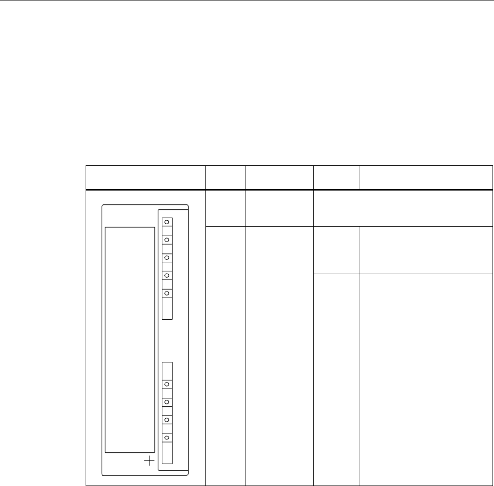
7.1.4 Addressing
The address range of the 8xIQ-Sense module is 16 bytes I/O.
This is independent of the choice of channel profiles on the connected device
(i.e. the IQ profile IDs in HW Config).
Access to memory areas
A direct association exists between the number of the channel to which the IQ-Sense device
is connected (terminal) and the input and output data area of the module. Based on the
address range, the following addresses can be used to access the memory areas:
Address = module initial address + (channel no. x 2)
Communication modules
7.1 8xIQ-Sense
SIMATIC RF300
7-6 System Manual, Release 04/2006, J31069 D0166-U001-A2-7618
Example
Module initial address = 280
I/O address for channel 3: 286
,46HQVHGHYLFH
0
0ದ
0
0ದ
0
0ದ
0
0ದ
0
0ದ
0
0ದ
0
0ದ
0
0ದ
)URQW GRRULQWHULRU
FKDQQHO
7HUPLQDO
&KDQQHODGGUHVVHV
LQH[DPSOH
IRU,46HQVHGHYLFHV
&KDQQHOQR
FKDQQHO
FKDQQHO
FKDQQHO
FKDQQHO
FKDQQHO
FKDQQHO
FKDQQHO
,4
,4
,4
,4
,4
,4
,4
,4
/
0
IRU5)
,46HQVHGHYLFH
,46HQVHGHYLFH
,46HQVHGHYLFH
,46HQVHGHYLFH
,46HQVHGHYLFH
,46HQVHGHYLFH
,46HQVHGHYLFH
5)5
5)5
Figure 7-5 8xIQ-Sense module: Assignment of terminal pair to memory area
Note
A maximum of two read/write devices can be operated!
Each read/write device uses channel numbers 0 to 3 or 4 to 7.