Siemens RF350R Inductive Tag Reader User Manual RFID Systeme SIMATIC RF300
Siemens AG Inductive Tag Reader RFID Systeme SIMATIC RF300
Siemens >
Contents
- 1. Manual Part 1
- 2. Manual Part 2
- 3. Manual Part 3
Manual Part 3

Communication modules
7.1 8xIQ-Sense
SIMATIC RF300
System Manual, Release 04/2006, J31069 D0166-U001-A2-7618 7-7
7.1.5 Technical data
Voltages and currents
Rated supply voltage
Reverse polarity protection
24 V DC
yes
Galvanic isolation
• Between the channels
• Between channels and backplane bus
no
yes
Permissible potential difference
Between different circuits
75 V DC / 60 V AC
Insulation tested at 500 V DC
Current input
• from the backplane bus
• from L+ power supply
120 mA typical
500 mA max.
Module power loss 2.5 W typical
Module-specific data
Number of channels
Channels for RFID systems
8
2
Cable length, unshielded 50 m max.
Dimensions and weight
Dimensions w x h x d (mm) 40 x 125 x 120
Weight Approx. 235 g
7.1.6 Ordering data
8xIQ-Sense Order No.
SIMATIC S7-300
IQ-Sense SM338 for S7-300 and ET200M for the
connection of up to 8xIQ-Sense sensors
Optical sensors, ultrasonic sensors and RF
identification systems can be connected.
6ES7 3387XF000AB0
Accessories
M12 cable plug, 4-pole, with 5 m black PUR
cable, 4 x 0.34 mm2
3RX8000-0CB42-1AF0
M12 cable plug, 4-pole, with 10 m black PUR
cable, 4 x 0.34 mm2
3RX8000-0CB42-1AL0
Communication modules
7.2 ASM 452
SIMATIC RF300
7-8 System Manual, Release 04/2006, J31069 D0166-U001-A2-7618
7.2 7.2 ASM 452
7.2.1 Features
Field of application
The ASM 452 interface module is a MOBY module for operating MOBY and RF300
components with RS 422 over PROFIBUS DP-V1 on
• Any computers and PCs
• Any PLCs
When operating the interface module on a SIMATIC S7, function blocks are made available
to the user.
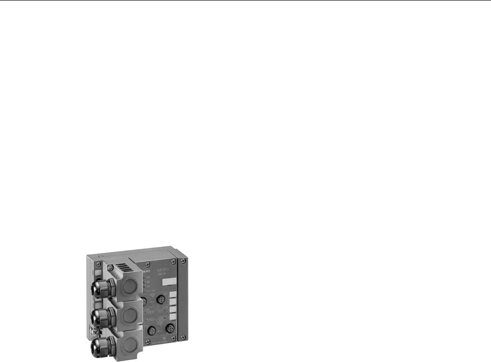
Figure 7-6 Interface module ASM 452
The ASM 452 is the result of consistent development of the familiar ASM 450/451 interface
modules. Optimal data throughput can be achieved even in large-scale PROFIBUS
configurations thanks to the use of acyclic data traffic on PROFIBUS DP V1. The minimum
cyclic data load of the ASM 452 on the PROFIBUS provides the user with the guarantee that
other PROFIBUS nodes (e.g. DI/DO) can still be processed at great speed.
The ASM 452 is an interface module for communication between PROFIBUS and the
RF310R with RS 422 interface. Through the ASM 452, the data on the RF320T, RF340T,
RF350T and RF360T transponders can be physically addressed ("Normal" addressing). In
SIMATIC S7, FC 45 is available for this purpose.
Communication modules
7.2 ASM 452
SIMATIC RF300
System Manual, Release 04/2006, J31069 D0166-U001-A2-7618 7-9
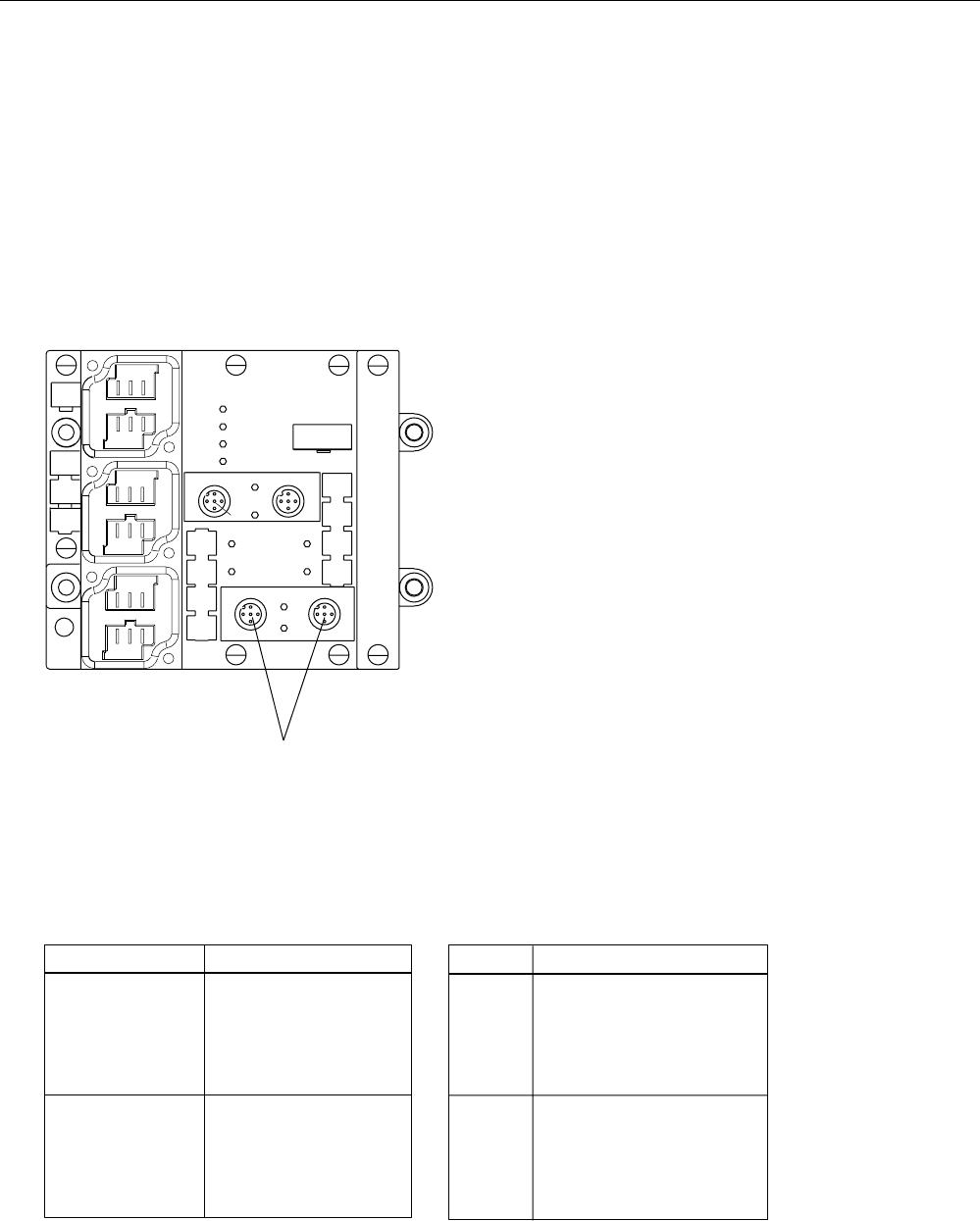
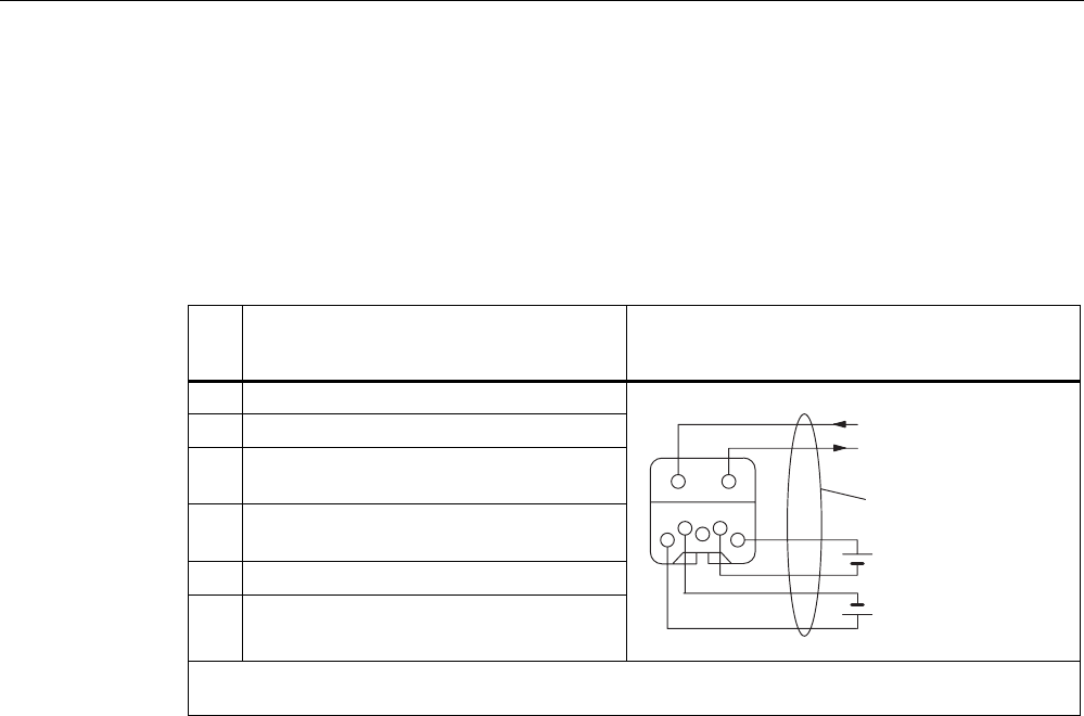
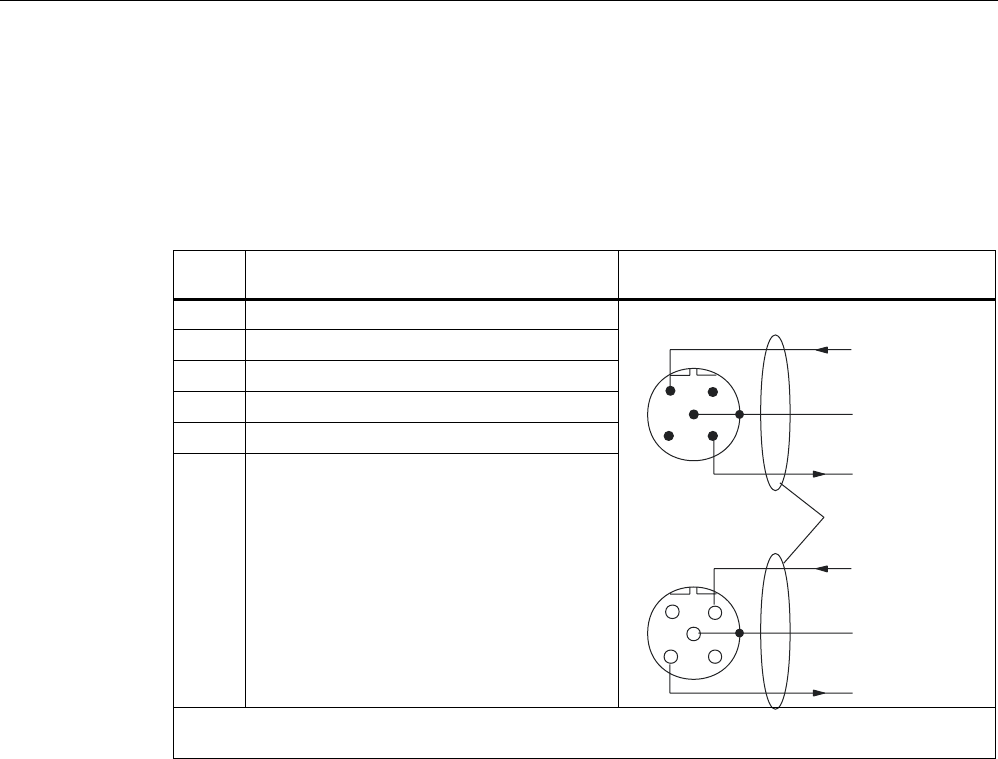
7.2.2 Pin assignment and display elements
Pin assignments
The figure below illustrates the pin assignments of ASM 452.
352),%86'3
6RFNHW
;DQG;
3LQDVVLJQPHQW
6LJQDO%UHG
3(
3(
6LJQDO$JUHHQ
/
0
6XSSO\
YROWDJH
/('VIRU5)DQG$60
5[' 5HDGHUDFWLYHZLWKFRPPDQG
35((55 7UDQVSRQGHUSUHVHQWRUHUURUGLVSOD\
35((55 IRUUHDGHU
7KHWUDQVSRQGHUSUHVHQWGLVSOD\DOZD\V
WDNHVSULRULW\7KHHUURULVRQO\LQGLFDWHG
ZKHQDWUDQVSRQGHULVQRW
SUHVHQW
7UDQVSRQGHUSUHVHQW
7KH/('LVSHUPDQHQWO\21,IPRUH
WKDQRQHWUDQVSRQGHULVLQWKHILHOGWKH
QXPEHU
RIWKHWUDQVSRQGHULVLQGLFDWHGZLWKVKRUW
IODVKHV1R
HUURUGLVSOD\
(UURUGLVSOD\
7KH/('LVSHUPDQHQWO\2))7KHODVW
HUURUQXPEHULVLQGLFDWHGZLWK
VKRUWIODVKHV
5HDGHU 5HDGHULVVHOHFWHG
5HDGHU 5HDGHULVVHOHFWHG
2QO\UHDGHUFDQEHVHOHFWHG
/('VIRU352),%86'3
6) 6\VWHP)DXOW
%) %XV)DXOW
21 /LWZKHQORJLFYROWDJHLVDSSOLHG
RQ$60JHQHUDWHGIURP
9VXSSO\YROWDJH
b9'& /LWZKHQ9VXSSO\YROWDJHLVDSSOLHG
WR$60
1RWFRQQHFWHG
3LQDVVLJQPHQWUHDGHU6RFNHW
1RWDYDLODEOHIRU
5)
;;
;;
$60b
; ;
; ;
;
;
;
9'&
5['
35((55
6/*
5['
6/*
35((55
6)
%)
21
3(
/
0
3(
/
0
;
5['
7['
7['
5['
3(
; ;
9 9
'2 ',
9 9
'2 ',
3( 3(
Figure 7-7 Pin assignment and LEDs of ASM 452
Communication modules
7.2 ASM 452
SIMATIC RF300
7-10 System Manual, Release 04/2006, J31069 D0166-U001-A2-7618
7.2.3 Configuration
Configuration
Hardware description
The ASM 452 has the same housing as the distributed I/O system ET 200X. General
information on ASM 452 (e.g. assembly, operation and wiring; general technical data) is
available in the ET200X manual (Order No. 6ES7 198-8FA00-8AA0). Descriptions of
accessories and network components can also be found in this manual.
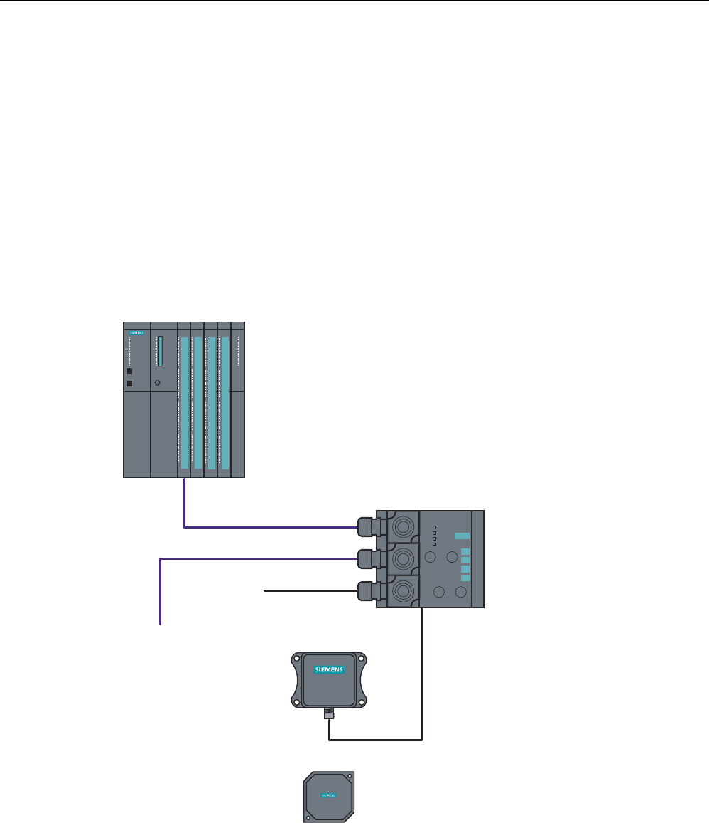
Configuration
5)[[7
5)[[5
352),%86FDEOHV
9IRU$60
WRRWKHU
352),%86
QRGHV
352),%86'3PDVWHUPRGXOH
HJ6&38
6,0$7,&
5)5
6,0$7,&
5)7
Figure 7-8 ASM 452 configurator
Communication modules
7.2 ASM 452
SIMATIC RF300
System Manual, Release 04/2006, J31069 D0166-U001-A2-7618 7-11
PROFIBUS configuration
The ASM 452 is integrated into the hardware configuration by means of a GSD file. The
ASM can then be configured using the HW Config of SIMATIC Manager or another
PROFIBUS tool.
A GSD file is provided for ASM 452 on the CD "RFID Systems Software & Documentation".
Operating mode of the ASM 452
The approved operating modes of ASM 452 are described in the GSD file. It is set using the
hardware configuration tool (e.g. STEP 7 HW Config).
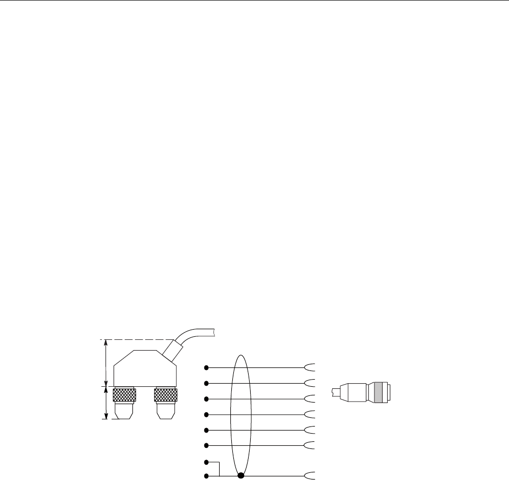
Reader connection system
A reader always occupies two M12 connector sockets on the ASM 452.
A pre-assembled cable therefore ensures easy connection of the reader (see figure below).
The connecting cable is available in lengths of 2 m (standard) and 5 m. Extensions are
possible up to 1000 m using connecting cables 6GT2891-… .
JUD\
JUHHQ
ZKLWH
EURZQ
\HOORZ
SLQN
VKLHOG
7ZRSLQ0
FLUFXODUFRQQHFWRUV
$60VLGH 5HDGHUVLGH
0SLQ
;
;
;
;
;
;
;
; ;
;
Figure 7-9 Connecting cable (2 m) ASM 452/473 ↔ RF310R reader with RS 422 (6GT2891-1CH20)
Communication modules
7.2 ASM 452
SIMATIC RF300
7-12 System Manual, Release 04/2006, J31069 D0166-U001-A2-7618
Cable installation
Signal M12 (reader side) Cable X1 / Data X2
24 V DC 1 Pink - 1
TX - 2 Yellow 4 -
GND 3 Gray - 3
TX + 4 Green 1 -
RX + 5 white 2 -
RX - 6 brown 3 -
- - -
Shield 8 + terminal piece Shield 5 5
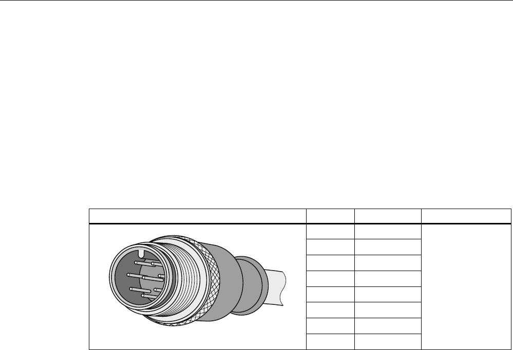
Cable installation ASM 452/473 ↔ RF310R reader with RS 422 (6GT2891-1CH20)
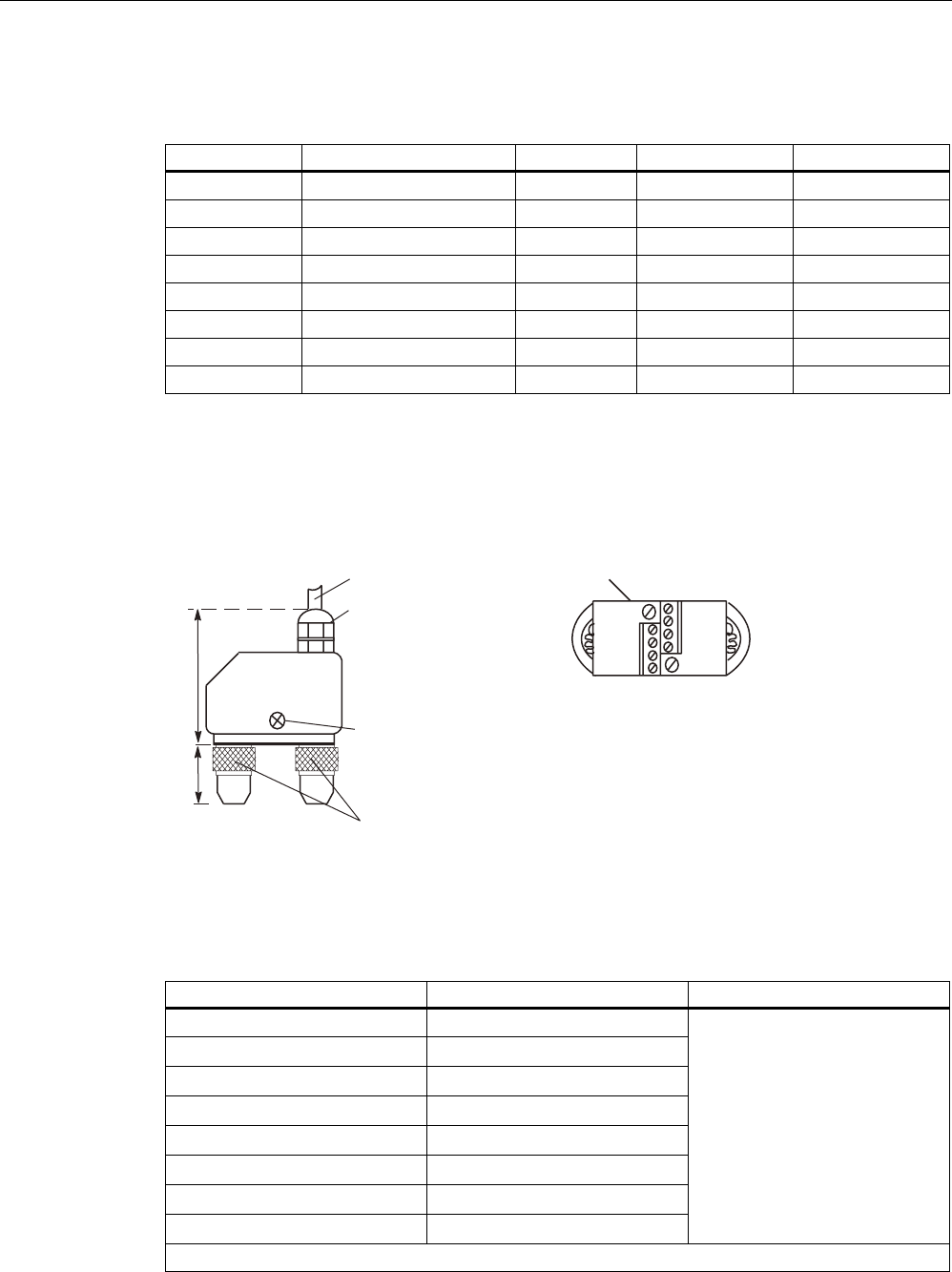
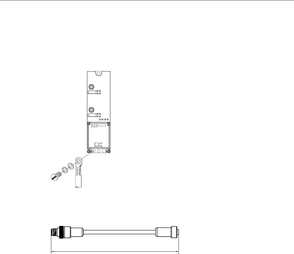
A reader cable connector with screw-type terminals is provided for users who want to
individually pre-assemble their own cables (see figure below). Cables and reader cable
connectors can be ordered from the MOBY catalog.
6
6
VFUHZV
IRURSHQLQJ
WKHFRQQHFWRU
&RQQHFWRU
0WR$60
'HJUHHRISURWHFWLRQ,3
3*FDEOHJODQG
PD[FDEOHGLDPHWHU
PPRQO\VFUHZGRZQ
DIWHUDVVHPEOLQJWKH
FRQQHFWRU
$60FDEOH*7 &RQQHFWRUFRYHUUHPRYHG
Figure 7-10 Cable connector ASM 452/473 ↔ RF310R reader with RS 422 (6GT2090-0BC00)
Pin assignment for ASM 452/473 cable connector
Connector pin Connection to pin of the reader Wire color
1 4
2 5
3 6
4 2
5 3
6 1
-
S 8 + terminal piece
Note data sheet provided by the
manufacturer
Pin 7 must not be connected.
Communication modules
7.2 ASM 452
SIMATIC RF300
System Manual, Release 04/2006, J31069 D0166-U001-A2-7618 7-13
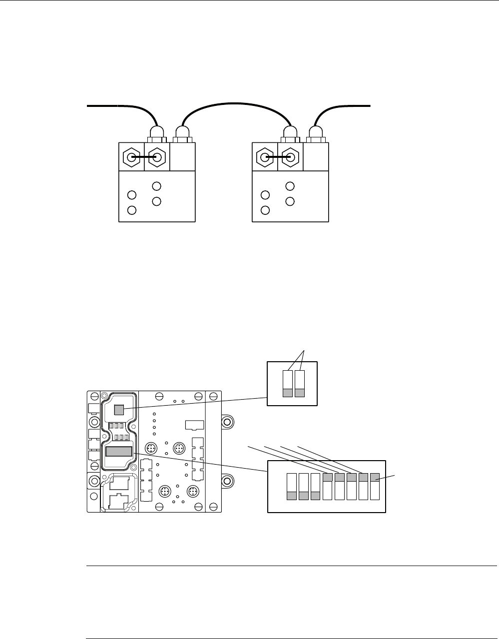
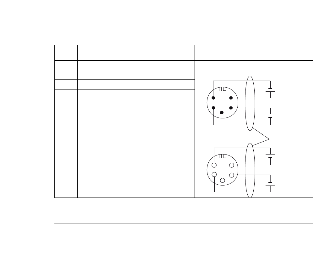
PROFIBUS cable with 24 V supply
The ASM 452 can also be operated with the "green" PROFIBUS cable. It is important to
ensure that a 24 V cable is connected from X12 to X13. The 24 V cable can be connected to
pins 5 and 6 in plug X12.
; ;
;
; ;
;
Figure 7-11 PROFIBUS cable with 24 V supply
PROFIBUS address and terminating resistor
You must remove the connector plate from the ASM before you set the
PROFIBUS address or connect the terminating resistor. The connector plate covers the DIL
switch. The position of the DIL switch in ASM is shown in the figure below with one setting
example for each case.
21
2II
RQ
([DPSOH352),%86DGGUHVVRQGHOLYHU\
([DPSOH7HUPLQDWLQJUHVLVWRU2II
$VGHOLYHUHGVWDWH
6WDQGDUG
PRGH
XVH*6'ILOH
6,(0%
Figure 7-12 Setting the PROFIBUS address/connecting the terminating resistor
Note
• The PROFIBUS address in ASM 452 must always match the PROFIBUS address defined
in the configuring software for this ASM.
• To ensure that the terminating resistor functions correctly, you must always switch both
DIL switches of the terminating resistor to "on" or "off".

Communication modules
7.2 ASM 452
SIMATIC RF300
7-14 System Manual, Release 04/2006, J31069 D0166-U001-A2-7618
7.2.4 Technical data
Technical data
Table 7-2 Technical data for ASM 452
ASM 452 with FC 45
Serial interface to the user PROFIBUS DP-V1
Procedure after connection EN 50170 Vol. 2 PROFIBUS
PG 11 cable gland
PROFIBUS and power supply connectors are not included
in the scope of delivery
Transmission rate 9600 baud to 12 Mbaud (automatic detection)
Max. block length 2 words cyclic/240 bytes acyclic
Serial interface to the RF3xxR
Connector 2 x M12 coupler plug
Max. cable length 2 m = Standard length, 5 m, 10 m, 20 m and 50 m,
(up to 1000 m on request)
Readers that can be connected 1x RF3xxR with RS 422 interface
Software functions
Programming Depending on the PROFIBUS DP master
Function blocks for SIMATIC S7 FC 45
Transponder addressing Direct access via addresses
Commands Initialize transponder, read data from transponder, write
data to transponder
Multi-tag capability No
S7 data structures via UDTs Yes
Power supply
Rated value 24 V DC
Permissible range 20 V to 30 V DC
Current consumption Max. 180 mA; typ. 130 mA (without reader)
Digital inputs none
Digital outputs none
Ambient temperature
During operation 0 °C to +55 °C
Storage and transport -40 °C to +70 °C
Dimensions (W x H x D) in mm 134 x 110 x 55 (without bus connector)
Fixing 4 M5 screws;
for mounting on any plate or wall
Weight, approx. 0,5 kg
Degree of protection IP67
MTBF (at 40 °C) 30 • 104 hours = 34 years

Communication modules
7.2 ASM 452
SIMATIC RF300
System Manual, Release 04/2006, J31069 D0166-U001-A2-7618 7-15
7.2.5 PROFIBUS Diagnosis
PROFIBUS Diagnosis
The following table lists possible error indications with their meanings and provides
remedies.
Table 7-3 LED indication for PROFIBUS diagnosis
"BF" LED "SF"LED Cause of error Error correction
• ASM 452 is in start-up mode. -
• The connection to the DP master
has failed.
• ASM 452 not detecting a baud
rate.
• Check the PROFIBUS DP
connection.
• Check the DP master.
ON *
• Bus interrupt
• DP Master not functioning
• Check all cables on your
PROFIBUS DP network.
• Check whether the connector
plugs for PROFIBUS DP are
securely plugged into the
ASM 452.
flashes ON • The configuration data sent to
the ASM 452 by the DP master
do not match the configuration of
the ASM 452.
• Check the configuration of
the ASM 452 (input/output,
PROFIBUS address).
• Correct GSD file being used?
– SIEM80B6.GSD for
ASM 452
flashes Off • ASM 452 has detected the baud
rate, but is not being addressed
by the DP Master.
• ASM 452 has not been
configured.
• Check the PROFIBUS
address set on the ASM 452
or in the configuration
software.
• Check the configuration of
the ASM 452 (station type).
ON flashes • There is a hardware defect in the
ASM 452.
• Replace the ASM 452.
Communication modules
7.2 ASM 452
SIMATIC RF300
7-16 System Manual, Release 04/2006, J31069 D0166-U001-A2-7618
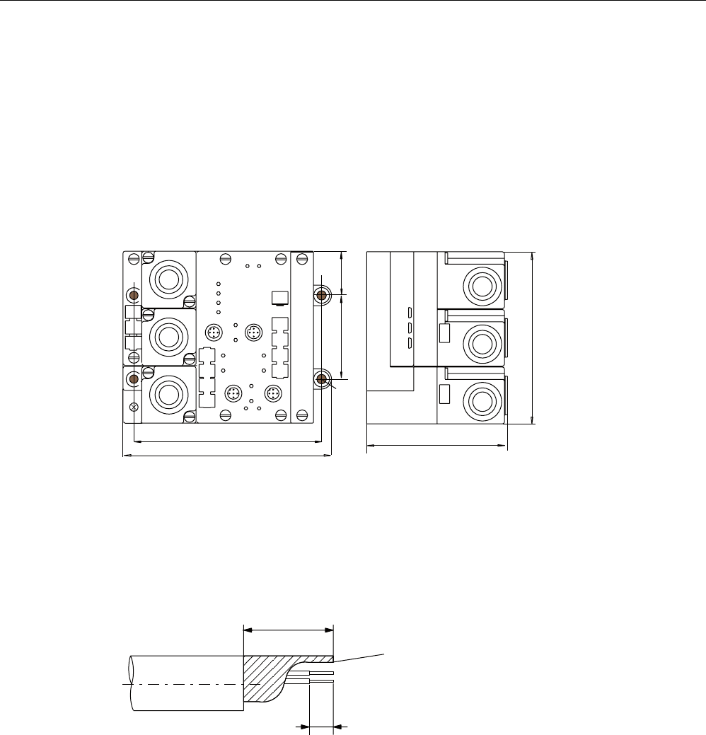
7.2.6 Dimensional drawings
Dimension drawing
The following figure shows the dimensional drawing of an ASM 452 with bus connectors.
You must add the length of the PG cable gland and the radius of the cable used to the
measured overall width and depth.
Figure 7-13 Dimensional drawing of ASM 452
Example of stripped lengths
The following diagram shows an example of stripped lengths. The lengths apply to all cables
which can be connected to the connector plugs. You must twist any shield braid present,
plug into a core end sleeve and cut off any excess.
7ZLVWHGDQG
WUXQFDWHG
VKLHOGEUDLGLQJ
Figure 7-14 Length of stripped insulation for PROFIBUS cables

Communication modules
7.2 ASM 452
SIMATIC RF300
System Manual, Release 04/2006, J31069 D0166-U001-A2-7618 7-17
7.2.7 Ordering data
Ordering data
Table 7-4 Ordering data for ASM 452 and accessories
Product description Order No.
ASM 452 interface module for PROFIBUS DP-V1, 1x RF310R with
RS 422 interface, without connector for 24 V DC and PROFIBUS
6GT2002-0EB20
Accessories:
Connector for PROFIBUS DP and 24 V supply 6ES7194-1AA00-0XA0
Connecting cable RF310R ↔ ASM 452
Plug-in cable, pre-assembled, length: 2 m (standard length) 6GT2891-1CH20
Plug-in cable, pre-assembled, length: 5 m 6GT2891-1CH50
Opt. Cable connector without read/write device cable
(for cable lengths > 20 m) ASM 452 ↔ reader
6GT2090-0BC00
M12 blanking cap for unused RF310R connection (1 pack =
10 pieces)
3RX9802-0AA00
CD "RFID Systems Software & Documentation" with FC 45, GSD
file
6GT2080-2AA10
Replacement part:
Connector plate; T functionality for PROFIBUS connection
6ES7194-1FC00-0XA0
FC 45 Reference Manual
German
English
French
Available in electronic form on
the CD "RFID Systems
Software & Documentation"
The ASM 456 plug-in cables 6GT2891-0Fxxx can be used as extension cables.
Communication modules
7.3 ASM 456
SIMATIC RF300
7-18 System Manual, Release 04/2006, J31069 D0166-U001-A2-7618
7.3 7.3 ASM 456
7.3.1 Description
Field of application
The ASM 456 interface modules are slave modules for operating RF300 components via the
PROFIBUS DP/DP-V1 on any control systems.
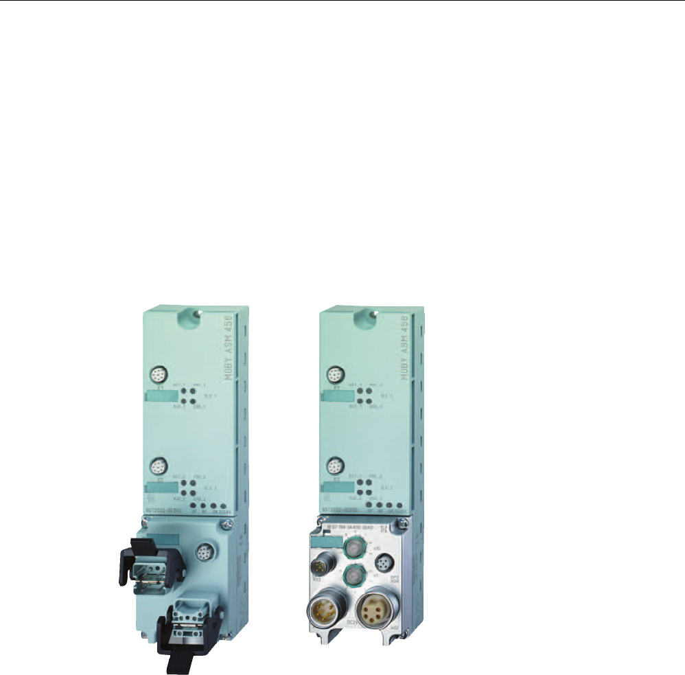
Figure 7-15 Interface module ASM 456 with ECOFAST connection block or M12, 7/8"
When operating the interface module on a SIMATIC S7, convenient function blocks are
made available to the user.

Communication modules
7.3 ASM 456
SIMATIC RF300
System Manual, Release 04/2006, J31069 D0166-U001-A2-7618 7-19
Features
The ASM 456 replaces the ASM 452 in terms of functionality and provides a simplified
connection system. You can continue to use the user software from ASM 452. Optimum data
throughput can be achieved through acyclic data traffic on the PROFIBUS DP V1 even when
using large PROFIBUS configurations. The minimum cyclic data load of the ASM 456 on the
PROFIBUS provides the user with the guarantee that other PROFIBUS consumers (e.g.
DI/DO) can still be processed at great speed.
Up to 2 readers can be operated in parallel on the ASM 456. The user can start a command
in parallel on 2 readers (via the corresponding FB/FC).
The transponder data are accessed by means of physical addressing of the reader. In
SIMATIC S7, the FC 45 is available for this purpose. The FC 45 provides the S7 user with a
simple-to-use interface with powerful commands (processing one complete transponder with
one command; command linking; S7 data structures via UDTs).
Other features
• Degree of protection IP67
• System integration with ECOFAST or M12, 7/8" concept
• T functionality, that is, a component can be replaced without adversely affecting other
modules with regard to bus communication and voltage supply
• Standardized PROFIBUS user interface for identification systems with PIB (Proxy Ident
Function Block; with later firmware version).
• Firmware update
• PROFIBUS interface module up to 12 Mbaud with automatic baud rate detection
• Parameterizable device-related diagnostics data with text display
• Support for I&M functionality (a mechanism for reading out information via the module
and saving system information such as function, installation date, installation location,
and comments.)
Communication modules
7.3 ASM 456
SIMATIC RF300
7-20 System Manual, Release 04/2006, J31069 D0166-U001-A2-7618
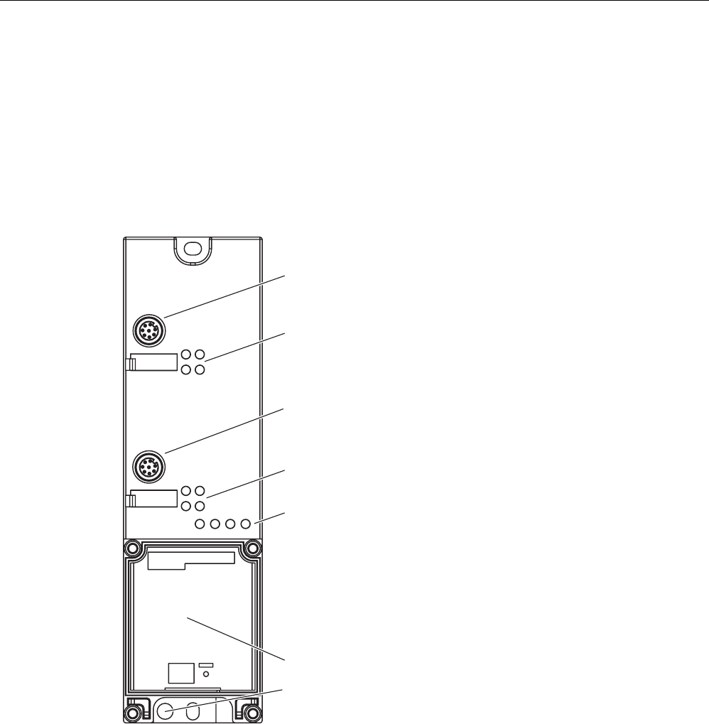
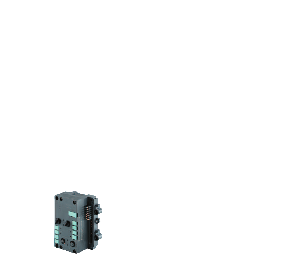
Design
The ASM 456 has the same housing as the distributed I/O system ET 200eco.
The ASM has a connection block for connecting up to the PROFIBUS DP which is available
as an option and the ECOFAST version or M12, 7/8".
The following figure shows the basic design of the ASM 456.
&RQQHFWRUVRFNHWIRUVWUHDGHU
6WDWXV/('VIRURSHUDWLRQ
RIWKHQGUHDGHU
6WDWXV/('VIRULQWHUIDFHPRGXOH
5HDGHU
6WDWXV/('VIRURSHUDWLRQ
RIWKHVWUHDGHU
&RQQHFWRUVRFNHWIRUQGUHDGHU
6SDFHIRUFRQQHFWLRQEORFN
3URWHFWLYHHDUWK
;
;
*7('
02%<$60
Figure 7-16 Basic design of the ASM 456
Communication modules
7.3 ASM 456
SIMATIC RF300
System Manual, Release 04/2006, J31069 D0166-U001-A2-7618 7-21
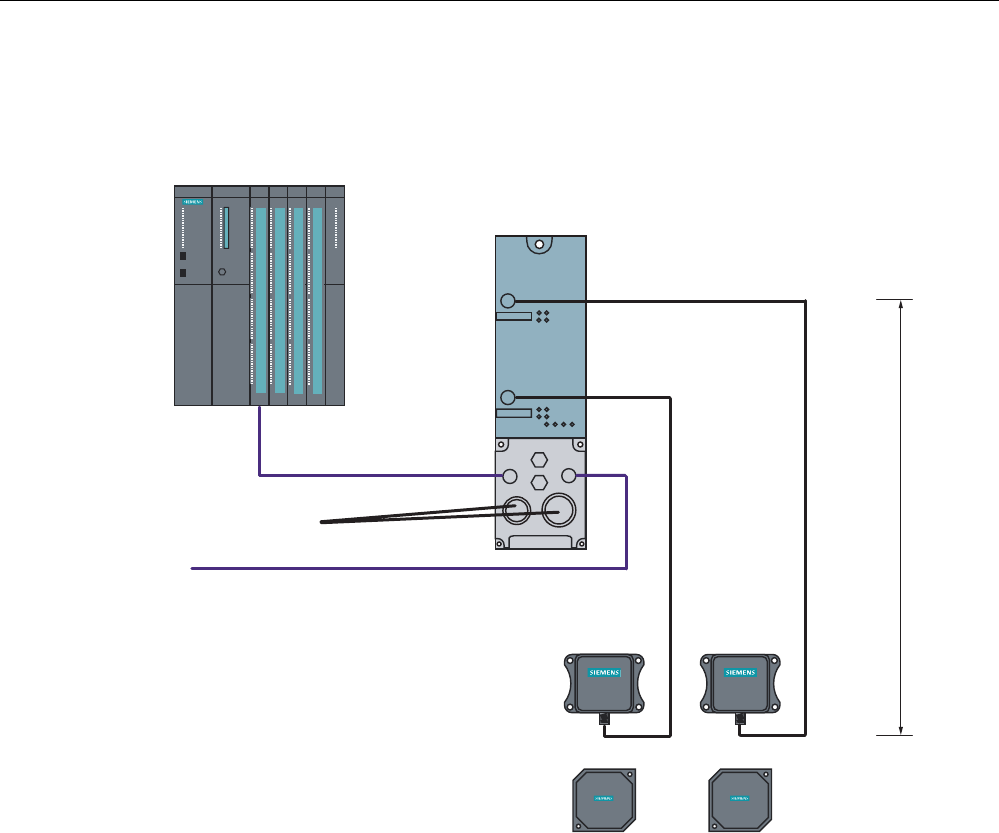
Configuration
The following figure shows how the ASM 456 is integrated in an automation system.
6,0$7,&
5)7
6,0$7,&
5)7
6,0$7,&
5)5
6,0$7,&
5)5
;
P
6WDQGDUGFDEOHOHQJWK
352),%86FDEOHV
9IRU$60
DQGUHDGHU
WRRWKHU
352),%86QRGHV
352),%86'3PDVWHUPRGXOH
HJ6&38
5HDGHU 5HDGHU
7UDQVSRQGHU
;
$60b
Figure 7-17 ASM 456 configurator
The ASM 456 is integrated into the hardware configuration by means of a GSD file. The
ASM can then be configured using HW Config of SIMATIC Manager or another PROFIBUS
tool (e.g. operating mode). The GSD file can be found on the "RFID Systems Software &
Documentation" CD or on the Internet.

Communication modules
7.3 ASM 456
SIMATIC RF300
7-22 System Manual, Release 04/2006, J31069 D0166-U001-A2-7618
7.3.2 Setting the PROFIBUS address
Features
The PROFIBUS address defines the address at which the ASM 456 distributed I/O system is
found on the PROFIBUS DP.
Requirements
• The PROFIBUS DP address for the ASM 456 is set on the connection block.
• Each address can be assigned only once on the PROFIBUS DP.
• The PROFIBUS address set must match the PROFIBUS address defined in the
configuring software (for the ASM 456).
• Changes to the PROFIBUS DP address only take effect once the mains have been
switched ON on the ASM 456.
Tools required for M12, 7/8” connection block
• Socket wrench 14 mm
• Screwdriver with 2.5 mm blade
Communication modules
7.3 ASM 456
SIMATIC RF300
System Manual, Release 04/2006, J31069 D0166-U001-A2-7618 7-23
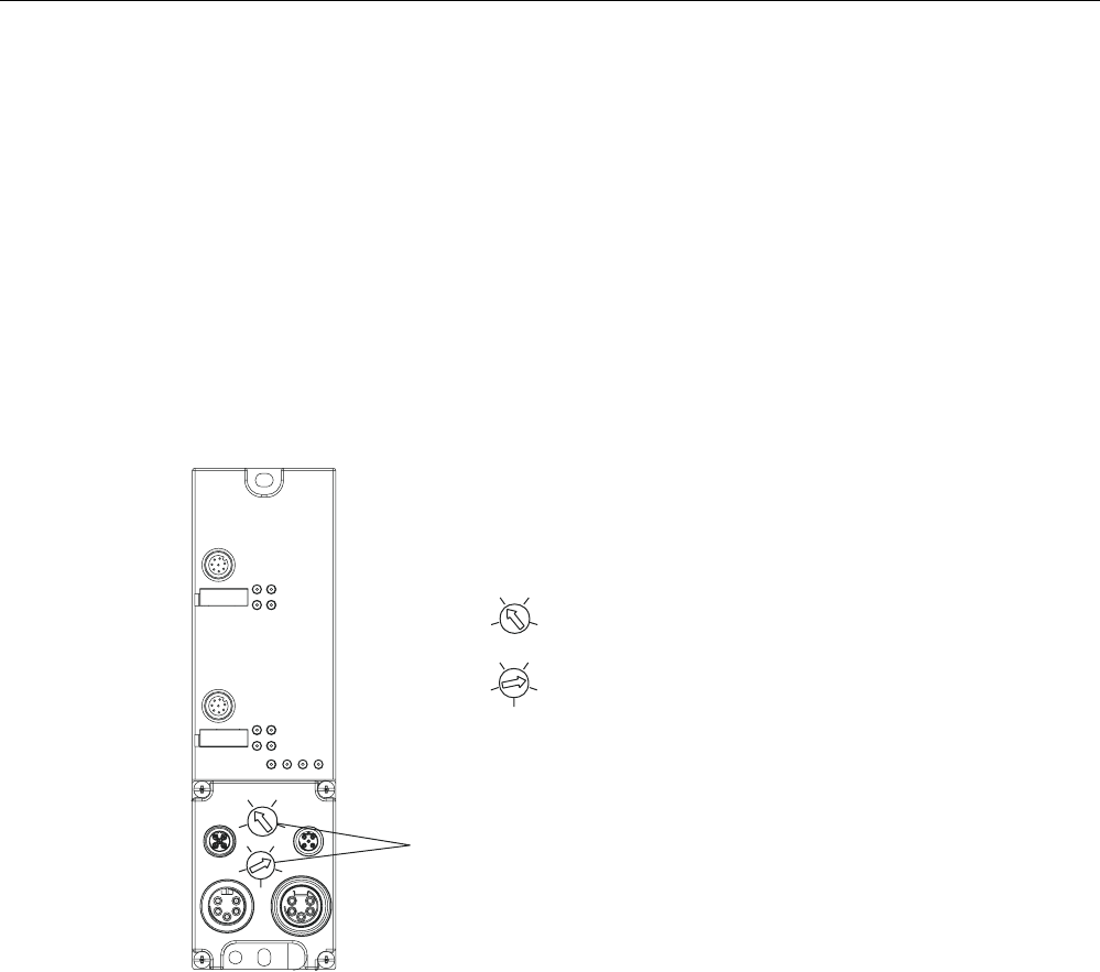
Setting PROFIBUS DP addresses on connection block M12, 7/8”
Valid PROFIBUS DP addresses are 1 to 99.
1. Remove the two seal caps from the rotary switches (if necessary, use a 14 mm socket
wrench).
2. Set the required PROFIBUS address on the rotary switches using a screwdriver.
– Lower rotary switch: 1st position
– Upper rotary switch: 10th position
3. Screw the two seal caps back onto the rotary switches
(torque: 0.5 Nm to 0.8 Nm.)
[
[
[
[
5RWDU\VZLWFKIRU
352),%86DGGUHVV
3RVLWLRQ
3RVLWLRQ
352),%86DGGUHVV([DPSOH
Figure 7-18 Setting PROFIBUS addresses on connection block M12, 7/8”
Communication modules
7.3 ASM 456
SIMATIC RF300
7-24 System Manual, Release 04/2006, J31069 D0166-U001-A2-7618
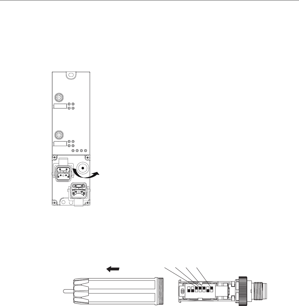
Setting PROFIBUS DP addresses on connection block ECOFAST
Valid PROFIBUS DP addresses are 1 to 99.
1. Loosen the screw connection of the configuration plug with the ECOFAST connection
block and remove the plug.
Figure 7-19 Loosening the configuration plug's screw connection
2. Loosen the screw connection for the cover cap on the configuration plug and remove the
latter.
3. Set the PROFIBUS address using the DIL switches.
([DPSOH352),%86DGGUHVV
21 21
Figure 7-20 Setting PROFIBUS address on configuration plug
4. Screw the cover cap back down, plug the configuration plug onto the connection block and
screw the configuration plug to the connection block.
Communication modules
7.3 ASM 456
SIMATIC RF300
System Manual, Release 04/2006, J31069 D0166-U001-A2-7618 7-25
7.3.3 Wiring up ASM 456
Wiring ECOFAST connector plugs
The table below contains the connector assignment for the ECOFAST connector plugs
Table 7-5 Connection assignment for ECOFAST connector plugs
Pin Assignment View of ECOFAST connector plug
(wiring end for supply and loop-through
connection)
A PROFIBUS DP signal A
B PROFIBUS DP signal B
1 Electronics / encoder supply (1L+)
(voltage supply for ASM 456 and reader)
2 Ground for electronic / encoder supply
(1M)
3 Ground for load voltage supply (2M)
4 Load voltage supply (2L+)
(unused on ASM 456)
$%
/
/
6LJQDO$
6LJQDO%
(&2)$67K\EULGFDEOH
*) You will find the assembly instructions in the packaging of the Han Brid Cu cable connector and/or
Han Brid Cu cable socket.
Communication modules
7.3 ASM 456
SIMATIC RF300
7-26 System Manual, Release 04/2006, J31069 D0166-U001-A2-7618
Wiring M12, 7/8” connector
The tables below contain the connector assignment for the M12, 7/8” connector:
Table 7-6 Connection assignment for M12 connector (PROFIBUS DP)
Pin Assignment View of M12 connector
(wiring side)
1 Supply positive (P5V2) *
2 Data line A (RxD / TxD-N)
3 Data reference potential (M5V2) *
4 Data line B (RxD / TxD-P)
5 Shield
Thread Shield
6LJQDO$JUHHQ
6LJQDO%UHG
6KLHOG
6XSSO\'3
6LJQDO$JUHHQ
6LJQDO%UHG
6KLHOG
%XVFDEOH
FRUHVKLHOGHG
/RRSWKURXJK
FRQQHFWLRQ'3
*) Can only be used for the M12 terminating resistor. Looping the voltage through to the next
connector via a 5-core cable is not permitted.
Communication modules
7.3 ASM 456
SIMATIC RF300
System Manual, Release 04/2006, J31069 D0166-U001-A2-7618 7-27
Table 7-7 Connection assignment for 7/8” connector (supply voltages)
Pin Assignment View of 7/8” connector
(wiring side)
1 Ground for load voltage supply (2M)
2 Ground for electronic / encoder supply (1M)
3 PE
4 Electronics / encoder supply (1L+)
(voltage supply for ASM 456 and reader)
5 Load voltage supply (2L+)
(unused on ASM 456)
/
/
/
/
6XSSO\;
FRUHFDEOH
/RRSWKURXJK
FRQQHFWLRQ;
Note
When connecting up the supply voltage, we recommend that the cable 6XV1 822-5B... (5 x
1.5 mm2 pre-assembled with 7/8" connectors) is used.
If you want to assemble the cable yourself, then the conductor cross-section should be
1.5 mm2.
Communication modules
7.3 ASM 456
SIMATIC RF300
7-28 System Manual, Release 04/2006, J31069 D0166-U001-A2-7618
Connecting the ASM 456 up to protective earth
1. Isolate the grounding cable and secure the cable lug.
2. Screw the cable lug down to the ASM 456 (M5 retaining bolt). The torque is 3 Nm.
Figure 7-21 Connecting the ASM 456 up to protective earth
Connecting RF310 reader to ASM 456
O
Figure 7-22 Connecting cable, l = 2 m, 5 m, 10 m, 20 m, 50m ( 6GT2891-0Fxxx)
Maximum cable length
The ASM 456 can be operated with any SLG configuration with a maximum cable length of
50 m.
Longer connecting cables of up to 1000 m are possible in some instances. The current
consumption of the connected reader must however be taken into account. A number of
cables must not be joined together to form a long cable due to the additional contact
resistances.
Communication modules
7.3 ASM 456
SIMATIC RF300
System Manual, Release 04/2006, J31069 D0166-U001-A2-7618 7-29
Cable assembly by the customer
A reader connection plug with screw-type terminals is available for users who want to make
their own cables.
Cables and reader cable connectors can be ordered according to the MOBY catalog.
For self-assembled cables, you will need cable to the following specifications:
7 x 0.25 mm2
LiYC11Y 7 x 0.25
M12 connectors can be purchased from appropriate electrical retailers (e.g. Binder in
Germany).
The pin assignment is listed in the following table.
Table 7-8 Pin assignment
M12 connector (male) Pin Signal Wire color
1 +24 V
2 −RxD
3 0 V
4 RxD
5 TxD
6 −TxD
7 Free
8 PE / shield
Note data sheet
provided by cable
manufacturer
Communication modules
7.3 ASM 456
SIMATIC RF300
7-30 System Manual, Release 04/2006, J31069 D0166-U001-A2-7618
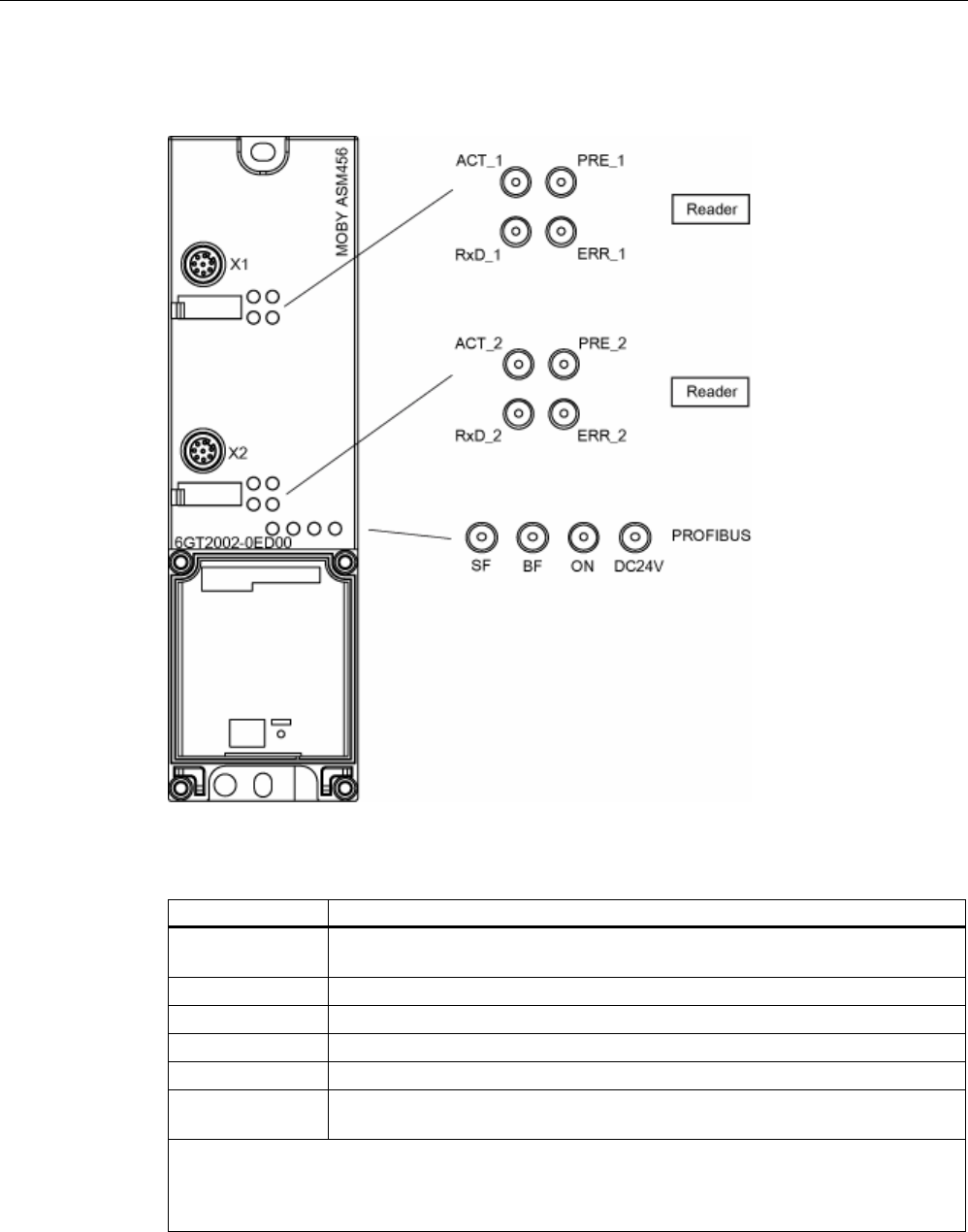
7.3.4 Diagnosis using LEDs
The following figure shows details of the LEDs of the ASM 456.
Figure 7-23 LEDs of the ASM 456
Table 7-9 Status LEDs for ASM 456
LEDs Meaning*
ON Lights up when there is logic voltage at the ASM (is generated by the 24 V
supply voltage.)
24 V DC Lights up when the 24 V supply voltage is connected to the ASM.
ACT_1, ACT_2 The corresponding reader is active in processing a user command.
ERR_1, ERR_2 * A flashing pattern indicates the last error to occur.
PRE_1, PRE_2 ** Indicates the presence of a transponder.
RxD_1, RxD_2 Indicates live communication with the reader. May also indicate malfunctions on
the transponder.
*) The meaning of the individual flash patterns and the associated fault descriptions can be found in
the relevant FB and FC documentation.
**) In multitag mode, this LED uses a flash interval to indicate the number of data media currently
within the range of influence of the reader.

Communication modules
7.3 ASM 456
SIMATIC RF300
System Manual, Release 04/2006, J31069 D0166-U001-A2-7618 7-31
Table 7-10 LED display for PROFIBUS diagnosis
BF SF Cause of error Error handling
• ASM is in start-up mode. –
• Connection to DP Master failed.
• ASM not detecting a baud rate
• Check the PROFIBUS DP
connection.
• Check the DP Master
On –
• Bus interrupt
• DP Master not functioning
• Check all cables on your
PROFIBUS DP network.
• Check whether the connector
plugs for the PROFIBUS DP are
securely plugged into the ASM.
flashes On • The project data sent to the ASM by
the DP Master do not match the
configuration of the ASM.
• Check the project for the ASM
(input/output, PROFIBUS
address).
• Correct GSD file being used?
flashes – • ASM has detected the baud rate, but
is not activated by the DP Master.
• ASM has not been assigned project
plans.
• Check the PROFIBUS address set
in ASM and/or in the project
software.
• Check the project for the ASM
(station type).
On flashes • There is a hardware defect in the
ASM.
• Replace the ASM.
Off On • Diagnosis available • Evaluate the diagnostic
information.
On Off • The set PROFIBUS address is
incorrect or greater than 99.
• Set the address in the range 1 to
99 and carry out new ramp-up.
– = Status not relevant
Other ASM operating modes are indicated by the PRE, ERR, ACT, SF and ON LEDs:
ON SF PRE_1 ERR_1 ACT_1 PRE_2 ERR_2 ACT_2 Description
On Off Off Off On Off Off Off Ramp-up active
Off On Off On Off Off Off Off Checksum error at ramp-up
Off On Off Off Off Off On Off Firmware invalid
On On On On On On On On LED test for approximately 4 seconds;
otherwise firmware fault
Off On Off On On Off On On Checksum error at ramp-up
Off On On On On Off On On Checksum error of the firmware
Off On On On On On On On External RAM defective
Off On On Off On On On On DPC-RAM defective
Off On Off On On On On On ID error firmware
On – Off 1 x flash
every 3 s
Off Off 1 x flash
every 3 s
Off ASM successfully ramped up, waiting
for reset command
On – – Flashing Rapid
flashing
– Flashing Rapid
flashing
Firmware update; alternate flashing of
the error LEDs at approximately 1 Hz
– = not relevant

Communication modules
7.3 ASM 456
SIMATIC RF300
7-32 System Manual, Release 04/2006, J31069 D0166-U001-A2-7618
7.3.5 Technical data
Table 7-11 Technical data for ASM 456
Serial interface to the user PROFIBUS DP-V1
Procedure after connection EN 50170 Vol. 2 PROFIBUS
M12 and 7/8" technology / ECOFAST
Transmission rate 9600 baud to 12 Mbaud
(automatic detection)
Max. block length 2 words cyclic/240 bytes acyclic
Serial interface to the reader
• Connector 2 x M12 coupler plug
• Max. cable length 1000m, reader dependent; 2 m = Standard length;
(up to 1000 m on request)
Extension cable = 2 m, 5 m, 10 m, 20 m and 50 m
• Readers that can be connected 2 x reader
Software functions
Programming Depending on the PROFIBUS DP master
Function blocks:
• SIMATIC S5 –
• SIMATIC S7 FC 45 (normal addressing without multitag)
Transponder addressing Direct access via addresses
Commands Initialize transponder, read data from transponder,
write data to transponder, etc.
Supply voltage: 2
• Rated value 24 V DC
• Permissible range 20 V to 30 V DC
Current consumption 1 Max. 800 mA; typ. 80 mA (without reader)
Galvanic isolation Yes
Ambient temperature
• During operation 0 °C to +55 °C
• Storage and transport –40 to +70 °C
Dimensions (W x H x D) in mm
• ASM 456 only 60 x 210 x 30
• ASM 456 with ECOFAST connection block 60 x 210 x 60
Weight, approx. 210 g
Degree of protection IP67
MTBF (at 40 °C) 122 years
1) The power supply must deliver the required current of up to 800 mA for brief power failures ≤ 20
ms.
2) All supply voltages and signal voltages must be protective low level voltage (SELV/PELV acc. to
EN 60950)
24V DC supply: Safety (electrical) isolation of low voltage (SELV / PELV acc. to EN 60950)
Communication modules
7.3 ASM 456
SIMATIC RF300
System Manual, Release 04/2006, J31069 D0166-U001-A2-7618 7-33
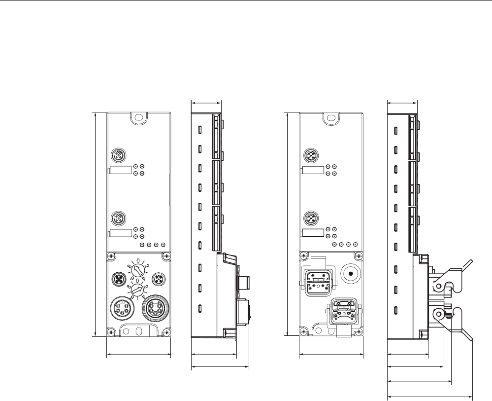
7.3.6 Dimensional drawings
The following figure shows the dimensional drawing of an ASM 456 with bus connection
block.
[
[
[
[
02%<$60
02%<$60
[
[
:LWKFRQQHFWLRQEORFN0 :LWKFRQQHFWLRQEORFN(&2)$67
Figure 7-24 Dimensional drawing of ASM 456 (in mm)

Communication modules
7.3 ASM 456
SIMATIC RF300
7-34 System Manual, Release 04/2006, J31069 D0166-U001-A2-7618
7.3.7 Ordering data
Table 7-12 Ordering data for ASM 456
Product description Order number
ASM 456 interface module
for PROFIBUS DP V1 max. 2 readers can be connected
6GT2002-0ED00
Accessories for ECOFAST connection:
Connection block ECOFAST 6ES7194-3AA00-0AA0
PROFIBUS ECOFAST hybrid plug 180
with pin insert (5 per pack) 6GK1905-0CA00
with socket insert (5 per pack) 6GK1905-0CB00
PROFIBUS ECOFAST termination plug with terminating resistor 6GK1905-0DA10
ECOFAST hybrid cable, pre-assembled 6XV1830-7B... 1)
ECOFAST hybrid cable, not pre-assembled, sold by the meter 6XV1830-7AH10
Accessories for M12 7/8" connection:
Connection block M12 6ES7194-3AA00-0BA0
M12 terminal resistor for PROFIBUS (5 per pack) 6GK1905-0EC00
PROFIBUS cable with M12 connectors, pre-assembled 6XV1830-3D... 1)
Cable for supply voltage with pre-assembled 7/8" connectors 6XV1822-5B... 1)
PROFIBUS FC standard non-pre-assembled cable;
max. length 1000 m
6XV1830-0EH10
PROFIBUS M12 connector plug (5 per pack)
with pin insert 6GK1905-0EA00
with socket insert 6GK1905-0EB00
Connector plug 7/8" for voltage (5 per pack)
with pin insert 6GK1905-0FA00
with socket insert 6GK1905-0FB00
Cable accessories:
Plug-in cable, pre-assembled, length 2 m (standard length) 6GT2891-0FH20
Plug-in cable, pre-assembled, length 5 m 6GT2681-0FH50
Plug-in cable, pre-assembled, length 10 m 6GT2681-0FN10
Plug-in cable, pre-assembled, length 20 m 6GT2681-0FN20
Plug-in cable, pre-assembled, length 50 m 6GT2681-0FN50
Angled extension for direct connection of reader to ASM 456 or for
extending any plug-in cables
6GT2891-0JH20
CD "RFID Systems Software & Documentation" with FC 45, GSD
file
6GT2080-2AA10
Other accessories for ASM 456 (network components) ET 200eco manual
6ES7198-8GA00-8AA0
Description of FC 45 (for ASM 456)
German
English
French
Available in electronic form on
the CD "RFID Systems
Software & Documentation"
1) These cables are available in different lengths. See Catalog IK PI for more details
Communication modules
7.4 ASM 473
SIMATIC RF300
System Manual, Release 04/2006, J31069 D0166-U001-A2-7618 7-35
7.4 7.4 ASM 473
7.4.1 Features
Field of application
The ASM 473 interface module is an RF300 module for SIMATIC S7. It can be plugged into
the ET 200X distributed I/O station and DESINA. ET 200X is operated by the user over
PROFIBUS DP V1. An S7-300 or S7-400 with integrated PROFIBUS connection can be
used as the controller.
ASM 473 supplements the SIMATIC S7 interface module ASM 475. The IP67 degree of
protection means that it can be installed and operated in the process without the need for an
additional protective housing.
To operate the ASM 473, an ET 200X basic module BM 141/142 with the order number
6ES7141-1BF11-0XB0 or 6ES7142-1BD21-0XB0 or a BM 143 is required.
The transponder data are accessed by means of physical addressing of the transponder.
For operation in a SIMATIC S7, the function FC 45 is available. The hardware of the ASM
473 is configured with an object manager (OM) that is integrated in the SIMATIC Manager.
Figure 7-25 Interface module ASM 473
Other features:
• Up to 7 ASM 473 interface modules can be operated simultaneously in an ET 200X
station.
• Any other I/O modules from the ET 200X spectrum can be operated with the ASM 473.
Communication modules
7.4 ASM 473
SIMATIC RF300
7-36 System Manual, Release 04/2006, J31069 D0166-U001-A2-7618
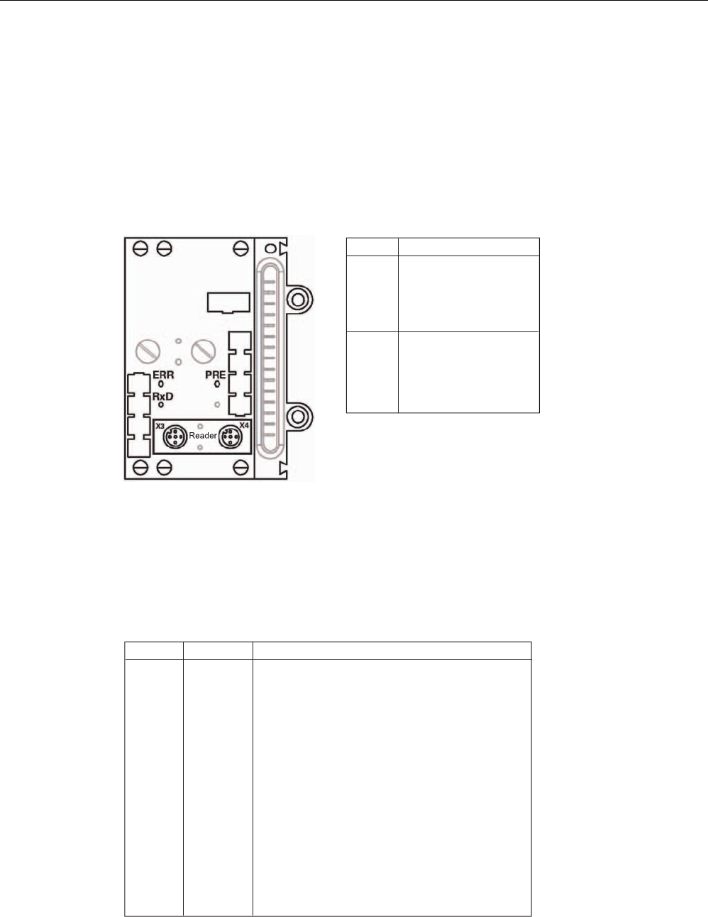
7.4.2 Pin assignment and display elements
Pin assignments
The figure below illustrates the pin assignment for the read/write device and the display
elements.
2))
+]
+]
2))21
+]
+]
+]
2))
;
;
21SHUP
2))21
5['
7['
7['
5['
3(
9
QF
9
QF
3(
(5535(
[IODVK
HYHU\V
6RFNHW 3LQDVVLJQPHQWUHDGHU
/('VIRU352),%86'3
*HQHUDOLQGLFDWRUV6)%)219'&DUHORFDWHGRQWKHEDVLFPRGXOH
RIWKH(7;
/('VIRU02%<
5[' 5HDGHUDFWLYHZLWKFRPPDQG
35( ,QGLFDWHVWKHSUHVHQFHRIDWUDQVSRQGHU
(55 (UURULQGLFDWHGE\IODVKLQJVHTXHQFH
7KHIROORZLQJ$60VWDWHVDUHDOVRLQGLFDWHGZLWKWKH/('V35(DQG
(55
'HVFULSWLRQ&DXVHV5HPHG\
+DUGZDUHLVGHIHFWLYH5$0IODVK
&KDUJHULVGHIHFWLYHFDQRQO\EHUHSDLUHGLQWKH
IDFWRU\
)LUPZDUHORDGLQJLVDFWLYHRUQR
ILUPZDUHGHWHFWHG
ൺ/RDGILUPZDUH
ൺ$60PXVWQRWEHVZLWFKHGRIIXQWLOORDGHG
)LUPZDUHORDGLQJWHUPLQDWHGZLWKHUURUV
ൺ5HVWDUWUHTXLUHG
ൺ/RDGILUPZDUHDJDLQ
ൺ&KHFNXSGDWHILOHV
2SHUDWLQJV\VWHPHUURU
ൺ6ZLWFK$60RU(7;EDVHVWDWLRQ2))21
$60KDVERRWHGDQGLVZDLWLQJIRUD5(6(7
LQLWBUXQIURPWKHXVHU
Figure 7-26 Interfaces and indicators of the ASM 473 for RF300
Communication modules
7.4 ASM 473
SIMATIC RF300
System Manual, Release 04/2006, J31069 D0166-U001-A2-7618 7-37
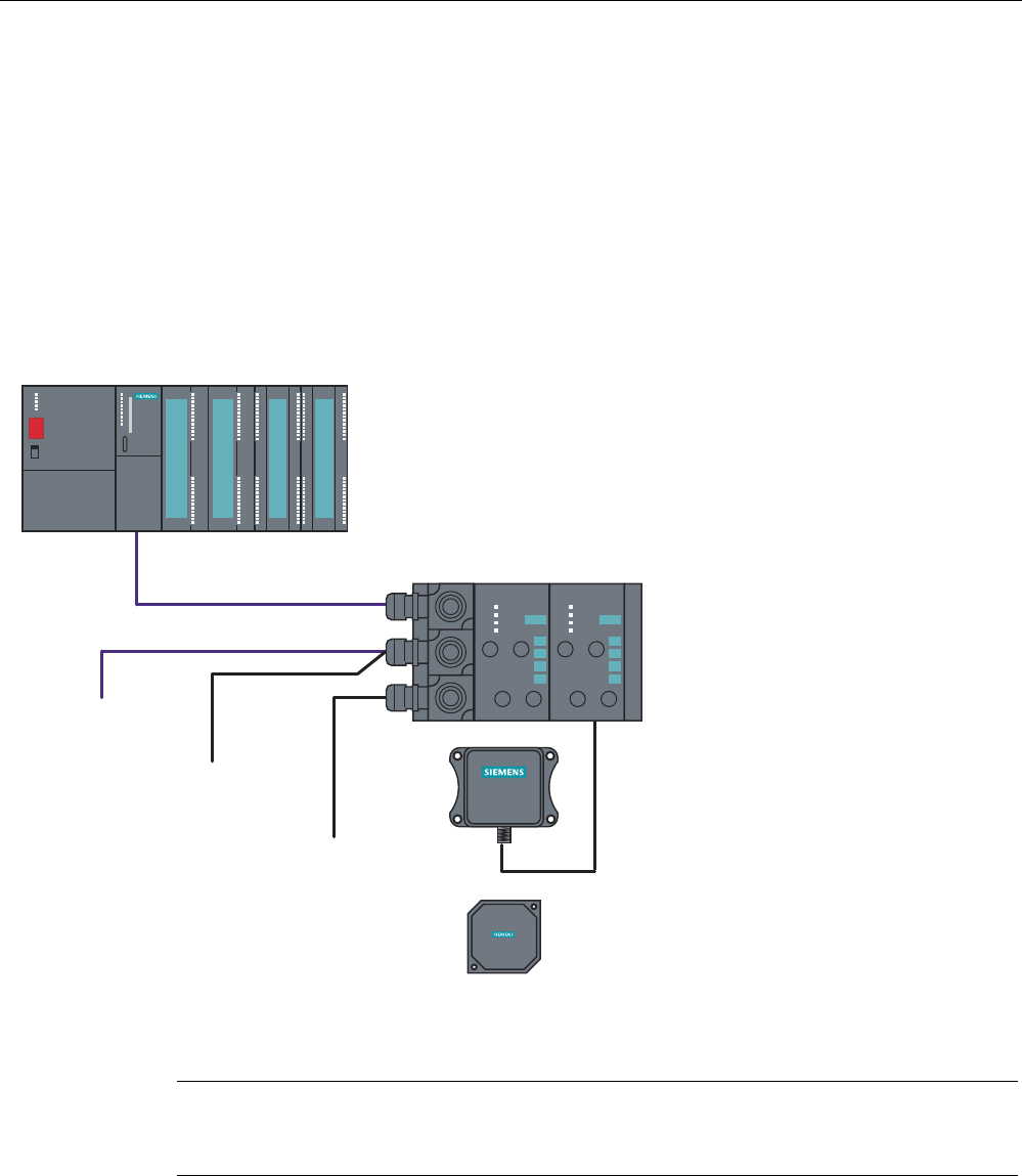
7.4.3 Configuration
Configuration
5)[[7
5)[[5
9VXSSO\
IRU5)5
9VXSSO\
IRU(7;
HOHFWURQLFV
WRRWKHU
352),%86QRGHV
352),%86'3PDVWHUPRGXOH
HJ6&38
FRQQHFWLRQRIDQRQ6LHPHQVPDVWHUSRVVLEOHVRRQ
%DVLFPRGXOH
(7;%0
(7;%0
'(6,1$%0
352),%86FDEOHV
6,0$7,&
5)5
6,0$7,&
5)7
Figure 7-27 Example - Configurator for ASM 473
Note
It differs from ASM 452 in that for ET 200X the 24 V supply must be connected to the
PROFIBUS connector and on the load voltage connector (see the ET 200X manual).

Communication modules
7.4 ASM 473
SIMATIC RF300
7-38 System Manual, Release 04/2006, J31069 D0166-U001-A2-7618
Basic module - Requirements for operation of ASM 473
The following table indicates the status of the ET 200X basic module of 10/2002. The
functionality of new basic modules is stored in HW Config of the SIMATIC Manager.
Table 7-13 Requirements for operation of ASM 473
Order number of the ET 200X
basic module
For operation with ASM 473
(6GT2002-0HA00)*
For operation with ASM 473
PARAM (6GT2002-0HA10)
6ES7141-1BF00-0XB0 No No
6ES7141-1BF00-0AB0 Yes Yes
6ES7141-1BF01-0XB0 No No
6ES7141-1BF10-0XB0 No No
6ES7141-1BF11-0XB0 Yes Yes
6ES7141-1BF40-0AB0 Yes Yes
6ES7142-1BD10-0XB0 No No
6ES7142-1BD11-0XB0 No No
6ES7142-1BD20-0XB0 No No
6ES7142-1BD21-0XB0 Yes Yes
6ES7142-1BD22-0XB0 No Yes**
6ES7143-1BF00-0AB0 Yes Yes
6ES7143-1BF00-0XB0 Yes Yes
6ES7147-1AA00-0XB0 No No
6ES7147-1AA01-0XB0 No Yes
* Discontinued
** Notes on operation:
In HW Config, please parameterize the module 6ES7142-1BD21-0XB0.

Communication modules
7.4 ASM 473
SIMATIC RF300
System Manual, Release 04/2006, J31069 D0166-U001-A2-7618 7-39
Example for a maximum configuration of ASM-473 on an ET 200X
5)[[7
5)[[5
6,0$7,&
5)5
6,0$7,&
5)5
6,0$7,&
5)5
6,0$7,&
5)5
6,0$7,&
5)5
6,0$7,&
5)5
6,0$7,&
5)5
6,0$7,&
5)7
0D[$60FDQEHRSHUDWHGLQDQ(7;
Figure 7-28 Example for a maximum configuration of ASM 473 on an ET 200X
Depending on the PROFIBUS master, up to 123 ET 200X modules can be run on one
PROFIBUS branch.
Hardware configuration
The ASM 473 is integrated in the hardware configuration of the SIMATIC Manager by calling
Setup.exe in the directory daten\S7_OM on the "RFID Systems Software & Documentation"
CD. Currently, the ASM 473 cannot be integrated in masters of other manufacturers.
Reader connection system
A reader always occupies the two M12 connection sockets X3 and X4 on the ASM 473. A
prefabricated cable makes it easy to connect the reader. The standard version of the
connecting cable is 2 m in length. Other cable lengths are available on request.
For customers who want to assemble their own cables, an ASM cable connector with screw-
type terminals is available. Cables and ASM cable connectors can be ordered from the
MOBY catalog.

Communication modules
7.4 ASM 473
SIMATIC RF300
7-40 System Manual, Release 04/2006, J31069 D0166-U001-A2-7618
7.4.4 Technical data
Technical data
Table 7-14 Technical data for ASM 473
Interface for ET 200X SIMATIC S7 I/O bus
cyclic/acyclic services
Communication 2 words cyclic/238 bytes acyclic
Command buffer in ASM 142 x 238 bytes
Serial interface to the reader
• Connector 2 x M12 coupler plug
• Max. cable length 2 m = standard length; other pre-assembled
cables = 5 m, (up to 1000 m on request)
• Readers that can be connected 1 x reader RF310R with RS 422
Software functions
Programming Depending on the PROFIBUS DP master
Function blocks for SIMATIC S7 FC 45
MDS addressing Direct access via addresses
Commands Initialize transponder, read data from
transponder, write data to transponder, etc.
PROFIBUS Diagnosis Yes; in accordance with ET 200X basic station
S7 diagnostics Yes, can be called up via S7 OM
Reloadable firmware Yes, via S7 OEM
Power supply 1
• Rated value 24 V DC
• Permissible range 20.4 V to 28.8 V DC
Current consumption Typ. 75 mA; max. 500 mA
(or see Technical Data of the connected reader)
Power dissipation of the module Typically 1.6 W
Digital outputs/inputs Via expansion modules from the ET 200X
spectrum
Ambient temperature
• During operation 0 °C to +55 °C
• Storage and transport -40 °C to +70 °C
Dimensions (W x H x D) in mm
• Single unit 87 x 110 x 55
• Width module 60 x 110 x 55
Fixing 2 M5 screws (customer side)
2 M3 screws (product side)
Degree of protection IP67
Weight, approx. 0.275 kg
For installation instructions and general technical data, see the ET 200X manual.
Communication modules
7.4 ASM 473
SIMATIC RF300
System Manual, Release 04/2006, J31069 D0166-U001-A2-7618 7-41
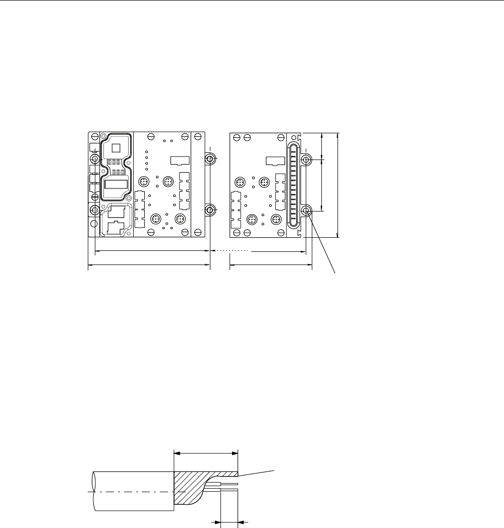
7.4.5 Dimensional drawings
Dimension drawing for mounting holes
The figure below shows the dimensions for the position of the holes for the fixing screws for
a basic module and an ASM 473 expansion module.
%0 $60b
Q[
Q 1XPEHURIH[SDQVLRQPRGXOHV
)RU0IL[LQJ
VFUHZ
Figure 7-29 Dimensions for fixing holes for basic modules and expansion modules
Example of stripped lengths
The following diagram shows an example of stripped lengths. The lengths apply to all cables
which can be connected to the connector plugs. You must twist any shield braid present,
plug into a core end sleeve and cut off any excess.
7ZLVWHGDQG
WUXQFDWHG
VKLHOGEUDLGLQJ
Figure 7-30 Length of stripped insulation for PROFIBUS cables

Communication modules
7.4 ASM 473
SIMATIC RF300
7-42 System Manual, Release 04/2006, J31069 D0166-U001-A2-7618
7.4.6 Ordering data
Ordering data
Table 7-15 Ordering data for ASM 473
Order No.
Interface module ASM 473
1x RF310R reader with RS 422 interface can be connected
6GT2002-0HA10
Accessories:
Connecting cable ASM 473 ↔ Reader RF310R
Plug-in cable, pre-assembled, length 2 m (standard length) 6GT2491-1CH20
Plug-in cable, pre-assembled, length 5 m 6GT2491-1CH50
Opt. Cable connector without reader cable
(for cable lengths > 20 m) ASM 473 ↔ Reader
6GT2090-0BC00
CD "RFID Systems Software & Documentation" with FC 45,
GSD file
6GT2080-2AA10
FC 45 Reference Manual
German
English
French
Available in electronic form on the
CD "RFID Systems Software &
Documentation"
Communication modules
7.5 ASM 475
SIMATIC RF300
System Manual, Release 04/2006, J31069 D0166-U001-A2-7618 7-43
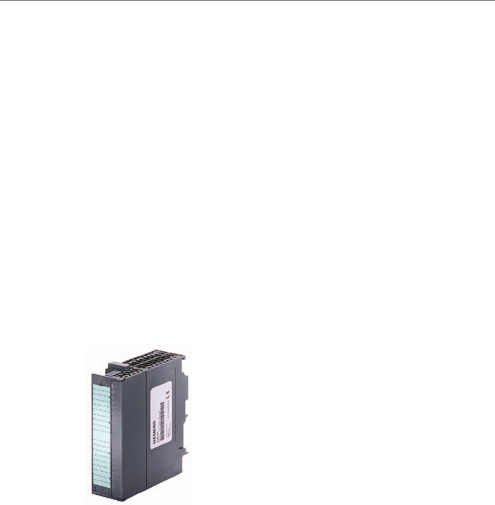
7.5 7.5 ASM 475
7.5.1 Features
Field of application
The ASM 475 interface module acting as the link between all RF300 systems and SIMATIC
S7-300 performs the functions of a communication module. It can be operated centrally in
the S7-300 or decentrally in an ET200M.
As many as eight ASM 475 interface modules can be plugged into one SIMATIC S7-300
rack and operated. In a configuration with several racks (max. four), the ASM 475 can be
plugged into and operated on any rack. This means that as many as 32 ASMs can be
operated in the maximum configuration of a SIMATIC S7-300. The ASM can also be
operated in the ET 200M distributed I/O on PROFIBUS. Operation in an S7-400 environment
is therefore problem-free. Up to 7 ASMs can be operated on each ET200M.
Error messages and operating states are indicated by LEDs.
A configuration that is resistant to interference is possible due to electrical isolation between
the read/write device and the SIMATIC S7-300 bus.
Figure 7-31 Interface module ASM 475
The ASM 475 with the order number 6GT2002-0GA10 is a parameterizable module. The
basic functions of the module are then already specified when the module is configured in
HW Config (e.g. standard addressing).
The data in the MDS is accessed direct by means of physical addresses using the ASM 475.
Operation in a SIMATIC S7 is controlled by the function FC 45.
ASM 475 and FC 45 form a unit that is used for reading the data of the MDS easily and at
optimal speed.
Communication modules
7.5 ASM 475
SIMATIC RF300
7-44 System Manual, Release 04/2006, J31069 D0166-U001-A2-7618
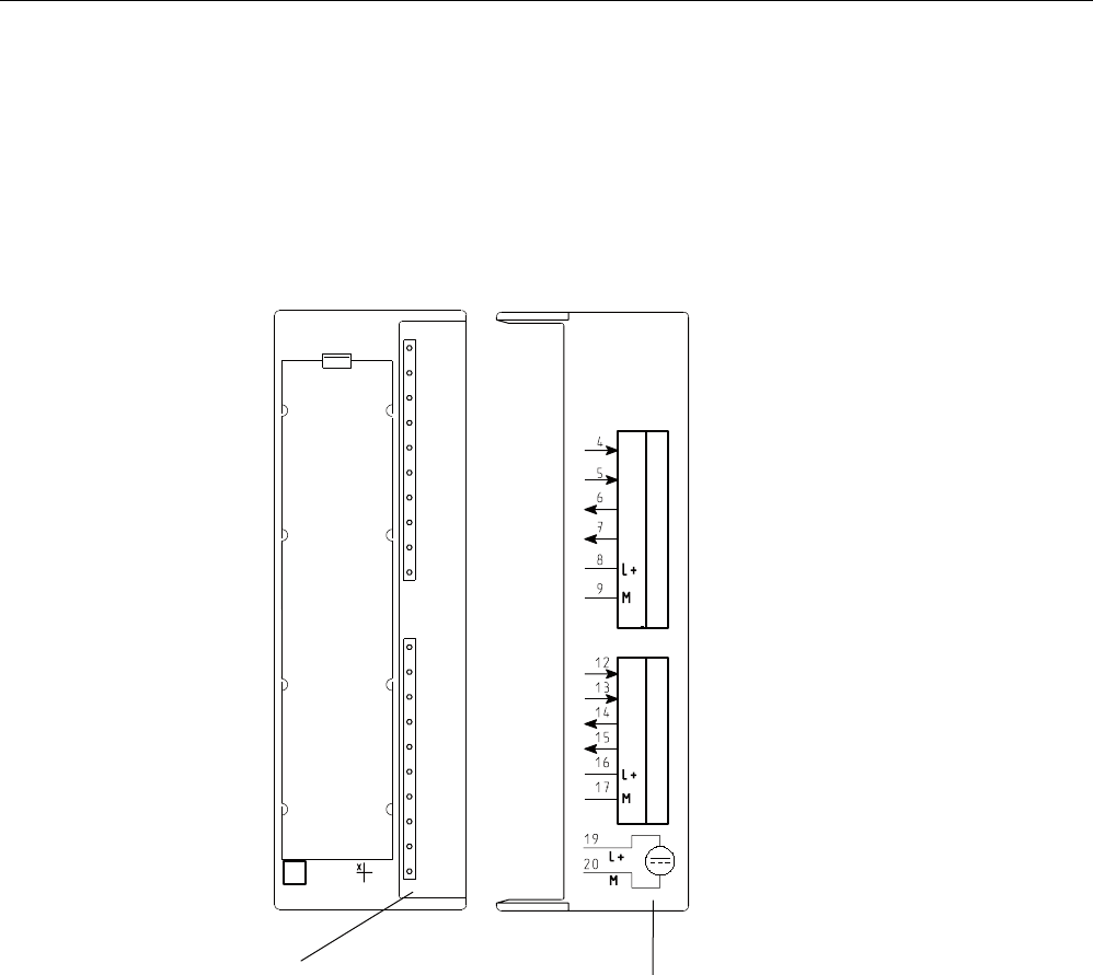
7.5.2 Indicators
Bezel and indicator elements
The figure below illustrates the bezel of the ASM 475 and the inside of the front door
complete with the associated connection diagram. The read/write devices must be
connected to the ASM in accordance with the connection diagram.
6WDWXVDQGHUURUGLVSOD\V &RQQHFWLRQGLDJUDP
7KHQXPEHUVRIWKH
FRQQHFWLRQVUHIHUWR
&RQQHFWRU;RIWKH
WRSHQFORVXUHVHFWLRQ
$60
02%<
6/*b
6
6
(
(
6
6
(
(
6)
9'&
$&7B
(55B
35(B
5['B
$&7B
(55B
35(B
5['B
6/*b
*7b*$
Figure 7-32 Bezel and inside of the front door of the ASM 475

Communication modules
7.5 ASM 475
SIMATIC RF300
System Manual, Release 04/2006, J31069 D0166-U001-A2-7618 7-45
Display elements on the ASM
Table 7-16 Function of the LEDs on the ASM 475
Light emitting diode Meaning
SF System fault (hardware error on ASM)
DC 5V 24 V are connected to ASM and the 5 V voltage on ASM is OK.
ACT_1, ACT_2 The corresponding reader is active in processing a user command.
ERR_1, ERR_2 A flashing pattern indicates the last error to occur. This display can be reset
using the parameter Option 1.
PRE_1, PRE_2 Indicates the presence of a transponder.
RxD_1, RxD_2 Indicates live communication with the reader. In the event of a fault on the
reader, this display may also be lit.
On the ASM 475, further operating states are indicated with the LEDs PRE, ERR and SF:
Table 7-17 Operating status display on ASM 475 via LEDs
SF PRE_1 ERR_1 PRE_2 ERR_2 Meaning
ON OFF/ON ON
(perm.)
OFF/ON ON
(perm.)
Hardware is defective (RAM, Flash, etc.)
ON OFF ON OFF OFF Charger is defective (can only be repaired in
the factory).
OFF 2 Hz OFF 2 Hz OFF Firmware loading is active or no firmware
detected
• Firmware download
• ASM must not be switched off
OFF 2 Hz 2 Hz 2 Hz 2 Hz Firmware loading
terminated with errors
• Restart required
• Load firmware again
• Check update files
Any
value
5 Hz 5 Hz 5 Hz 5 Hz Operating system error
• Switch ASM off/on
OFF OFF 1 flash
every 2 s
OFF 1 flash
every 2 s
ASM has booted and is waiting for a RESET
(init_run) from the user.
Communication modules
7.5 ASM 475
SIMATIC RF300
7-46 System Manual, Release 04/2006, J31069 D0166-U001-A2-7618
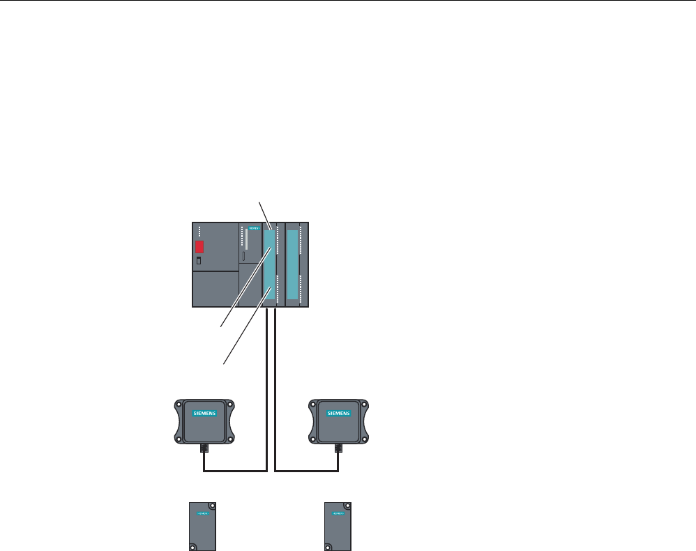
7.5.3 Configuration
Configuration
Centralized configuration with SIMATIC S7-300
6,0$7,&
5)5
6,0$7,&
5)5
6,0$7,&
5)7
6,0$7,&
5)7
2WKHUPRGXOHVIURPWKH6
UDQJHLQFOXGLQJ$60
$60FKDQQHO
5HDGHUZLWK56LQWHUIDFH
5HDGHU5HDGHU
7UDQVSRQGHU7UDQVSRQGHU
$60b
6
Figure 7-33 Configurator for ASM 475 with RF310R reader (centralized configuration)
Communication modules
7.5 ASM 475
SIMATIC RF300
System Manual, Release 04/2006, J31069 D0166-U001-A2-7618 7-47
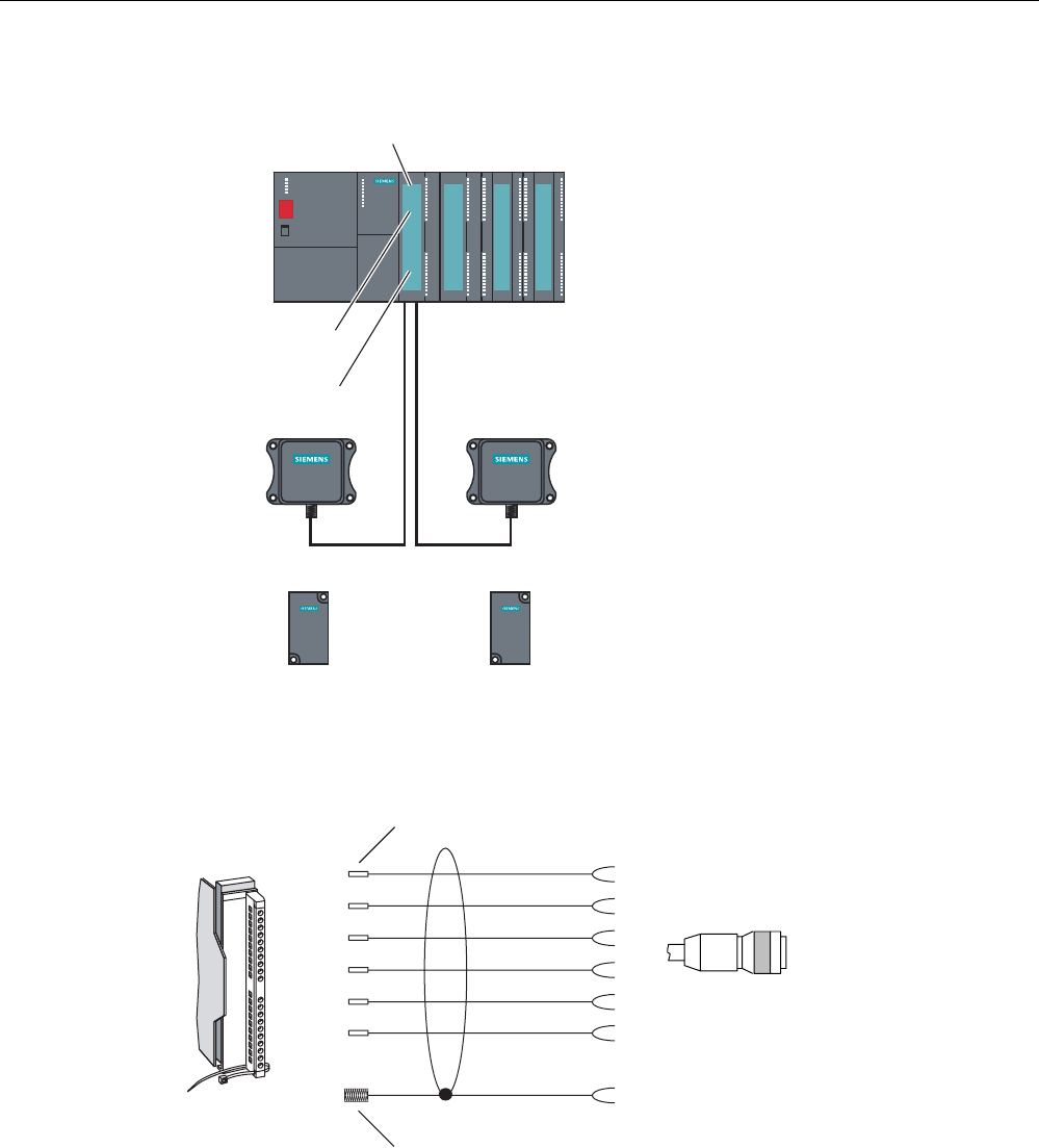
Distributed configuration with ET200M
6,0$7,&
5)5
6,0$7,&
5)5
6,0$7,&
5)7
6,0$7,&
5)7
2WKHUPRGXOHVIURPWKH6
UDQJHLQFOXGLQJ$60
$60FKDQQHO
5HDGHUZLWK56LQWHUIDFH
5HDGHU5HDGHU
7UDQVSRQGHU7UDQVSRQGHU
$60b
(70
Figure 7-34 Configurator for ASM 475 with RF310R reader (distributed configuration)
Reader connection system
&DEOHZLWKHQGVOHHYHV
JUD\
SLQN
\HOORZ
EURZQ
ZKLWH
VKLHOG
&DEOHVKLHOGH[SRVHG
$60VLGH 5HDGHUVLGH
JUHHQ
6/*FRQQHFWRU
6RFNHW
0SLQ
*7(ZLWKVWUDLJKW6/*FRQQHFWRUVWDQGDUG
Figure 7-35 Installation of connecting cable ASM 457-RF300-Reader with RS 422

Communication modules
7.5 ASM 475
SIMATIC RF300
7-48 System Manual, Release 04/2006, J31069 D0166-U001-A2-7618
Cable installation
Signal M12 Cable Finely-stranded
conductor
Labeling
24 V DC 1 white 1 1 Reader 2
8 -16
TX - 2 brown 2 1 Reader 2
7-15
GND 3 Green 3 1 Reader 2
9-17
TX + 4 Yellow 4 1 Reader 2
6-14
RX + 5 Gray 5 1 Reader 2
4-12
RX - 6 Pink 6 1 Reader 2
5-13
Shield 8 + terminal piece - 8
Cable assignment for connection of an RF300 reader to ASM 475

Communication modules
7.5 ASM 475
SIMATIC RF300
System Manual, Release 04/2006, J31069 D0166-U001-A2-7618 7-49
7.5.4 Technical data
Technical data
Table 7-18 Technical data for ASM 475
ASM 475 with FC 45
Serial interface for SIMATIC S7-300 or
ET200M
I/O bus; cyclic and acyclic services
Communication 2 words cyclic/238 bytes acyclic
Command buffer in ASM 475 70 x 238 bytes per RF310R reader
Serial interface to the reader
Connector Via screw-type terminal on front connector
The front connector is not included in the scope
of supply.
Max. cable length Pre-assembled cables = 2 m, 5 m,
(up to 1000 m on request)
Readers that can be connected 2 x RF310R reader with RS 422
parallel operation
Software functions
Programming Depending on the PROFIBUS DP master
Function blocks for SIMATIC S7 FC 45
Transponder addressing Direct access via addresses
Commands Initialize transponder, read data from
transponder, write data to transponder
Multitag mode No
S7 data structures via UDTs Yes
Power supply
Rated value 24 V DC
Permissible range 20.4 V to 28.8 V DC
Current consumption
Without reader for U = 24 V DC, max. 350 mA
With reader connected, max. 500 mA, per connected reader
Power dissipation of the module, typ. 2 Watts
Current consumption from I/O bus, max. 80 mA
Electrical isolation between S7-300 and RF300 Yes
V24 fuse to reader Yes, electronic
Ambient temperature
During operation
Horizontal installation of SIMATIC
Vertical installation of SIMATIC
0 to +60 °C
0 to +40 °C
Storage and transport -40 °C to +70 °C
Dimensions (W x H x D) in mm 40 x 125 x 120
Weight, approx. 0,2 kg

Communication modules
7.5 ASM 475
SIMATIC RF300
7-50 System Manual, Release 04/2006, J31069 D0166-U001-A2-7618
7.5.5 Ordering data
Ordering data
Table 7-19 Ordering data for ASM 475
Order No.
ASM 475 interface module for SIMATIC S7
2 x RF310R reader with RS 422 can be connected in
parallel, without front connector
6GT2002-0GA10
Accessories:
Front connector (1 x per ASM) 6ES7392-1AJ00-0AA0
Connecting cable ASM 475 ↔ RF310R
Plug-in cable, pre-assembled, length: 2 m (standard length) 6GT2891-0EH20
Plug-in cable, pre-assembled, length: 5 m 6GT2891-0EH50
Opt. Cable connector without reader cable
(for cable lengths > 50 m) ASM 475 ↔ reader
6GT2090-0BC00
Terminal element (1 x per reader cable) 6ES7390-5BA00-0AA0
Shield connecting element 6ES7390-5AA00-0AA0
CD "RFID Systems Software & Documentation" with FC 45,
S7 object manager
6GT2080-2AA10
FC 45 Reference Manual
German
English
French
Available in electronic form on the
CD "RFID Systems Software &
Documentation"
The ASM 456 plug-in cables 6GT2891-0Fxxx can be used as extension cables.

Communication modules
7.5 ASM 475
SIMATIC RF300
System Manual, Release 04/2006, J31069 D0166-U001-A2-7618 7-51

SIMATIC RF300
System Manual, Release 04/2006, J31069 D0166-U001-A2-7618 8-1
System diagnostics 8
8.1 8.1 Overview
Extended diagnostic functions with SIMATIC RF300
With SIMATIC RF300, extended diagnostic functions are available which simplify start-up
and maintenance.
These diagnostic data are accessed using the FC 45 function with the SLG STATUS and
MDS STATUS commands. These two commands can each be called in various modes
(subcommands) for which corresponding data structures (UDTs) are defined.
Command Mode
(subcommand)
Meaning
01 Hardware and firmware configuration, parameterization statusSLG STATUS
06 Communication error counter, current command status
01 Serial number of the tag (UID), memory configuration
EEPROM write-protection status
MDS STATUS
02 Serial number of the tag (UID), HF field strength value,
communication error counter, presence counter (duration)
Overview of the diagnostic functions

System diagnostics
8.2 Reader diagnostics with SLG STATUS
SIMATIC RF300
8-2 System Manual, Release 04/2006, J31069 D0166-U001-A2-7618
8.2 8.2 Reader diagnostics with SLG STATUS
The SLG STATUS command can be used to scan the status and diagnostics data of the
reader.
SLG STATUS (mode 01), UDT110
HW ASCII Type of hardware
(31 to 38 hex)
HW-V Binary
value
HW version
0 to FF hex
0 to FF hex
= Version (high byte): Unused
= Version (low byte)
Url-V Binary
value
Version of loader
0 to FF hex
0 to FF hex
= Version (high byte)
= Version (low byte)
FW ASCII
format
Type of firmware
FW-V Binary
value
Firmware version
0 to FF hex
0 to FF hex
= Version (high byte)
= Version (low byte)
TR Binary
value
Type of driver "1" = 3964R
TR-V Binary
value
Version of driver
0 to FF hex
0 to FF hex
= Version (high byte)
= Version (low byte)
SS Binary
value
RS 232 / RS 422
01 hex
= RS 422
Baud Binary
value
Baud rate
01 hex
02 hex
05 hex
= 19.2 Kbaud
= 57.6 Kbaud
= 115,2 Kbaud
mtag Binary
value
Number of MDSes
(Multitag/Bulk) that can be
processed in the antenna field
= 1 with single-tag mode (param
= 0x05, 0x25)
ANT Binary
value
Status of antenna
01 hex
02 hex
= Antenna On
= Antenna Off
ANW Binary
value
Presence mode
0
01 hex
= Operation without presence
= Operation with presence (see
ANW-MELD signal)

System diagnostics
8.2 Reader diagnostics with SLG STATUS
SIMATIC RF300
System Manual, Release 04/2006, J31069 D0166-U001-A2-7618 8-3
SLG STATUS (mode 06), UDT280
FZP Binary
value
0 … 255 = Error counter, passive (errors
during idle time)
ABZ Binary
value
0 … 255 = Abort counter
CFZ Binary
value
0 … 255 = Code error counter
SFZ Binary
value
0 … 255 = Signature error counter
CRCFZ Binary
value
0 … 255 = CRC error counter
BSTAT Binary
value
0 … 255 = Current command status
ASMFZ Binary
value
0 … 255 = Interface problems to host
(ASM/PC) parity, BCC, frame error
Note
All counter values are reset after reading (= SLG STATUS command executed).
Explanations:
• "FZP": Counts interference pulses when communication is not taking place with a
transponder. (e.g. EMC interference caused by contactors, motors, etc.). Counter values
can also be generated when a tag is located at the edge of the field even when there is
no external interference.
• "ABZ", "CFZ", "SFZ" and "CRCFZ" are protocol error counters that can be generated
during reader/tag communication. This can be caused by unsuitable reader/tag
positioning (e.g. tag on field boundary, several data carriers in the field) or external
electromagnetic interference.
To ensure clear diagnosis of the quality of communication, it is recommended that an SLG
STATUS command (mode 06) is executed following receipt of the presence command to
reset the error counter.
The protocol error counters are not mutually independent. If a code error (CFZ) occurs, this
will cause a secondary signature (SFZ) or CRC (CRCFZ) error.
• "BSTAT" is the status for the most recently executed command. A value other than 0
means that the previous command was repeated by the reader due to faults (see above).
• "ASMFZ" signals line-conducted communication interference between the communication
module (ASM) and the reader. Faults of this type can be caused by contact problems on
the connector or the cable connection.

System diagnostics
8.3 Transponder diagnostics with MDS STATUS
SIMATIC RF300
8-4 System Manual, Release 04/2006, J31069 D0166-U001-A2-7618
8.3 8.3 Transponder diagnostics with MDS STATUS
The MDS STATUS command can be used to scan the status and diagnostics data of the
transponder that is located within the antenna field.
MDS STATUS (mode 01), UDT260
UID Binary value 0 … 264 -1 = b0-31: 4 byte TAG ID, b32-63: 0
MDS type Binary value 0x01
0x02
0x03
= Transponder without FRAM
= Transponder with FRAM 8 KB
= Transponder with FRAM 32 KB
Lock
status
Binary value 0 … 255 = Content of lock-bit register (EEPROM addr.
0xFF18)
MDS STATUS (mode 02), UDT270
LFD Binary value 0 … 255 = Value for field strength
FZP Binary value 0 … 255 = Error counter (passive) ➙ errors during idle
time
FZA Binary value 0 … 255 = Error counter (active)
ANWZ Binary value 0 … 255 = Presence counter
Note
All counter values are reset when the tag exits the field or when the antenna is switched off.
Notes:
• "LFD" is a value for the field strength that is determined in the transponder. The lower the
value, the higher the field strength. A setpoint of < 28 hex signals reliable data transfer.
• "FZP" counts fault pulses when communication with a transponder is not taking place
(e.g. electromagnetic interference caused by contactors, motors, etc.). Counter values
can also be generated when a transponder is located at the edge of the field even when
there is no external interference.
• "FZA" counts errors that can occur during reader-to-transponder communication. This can
be caused by unsuitable reader/transponder positioning (e.g. transponder on field
boundary, several data carriers in the field) or external electromagnetic interference.
• "ANWZ" is the value for the time that the transponder remains in the field before the MDS
STATUS command (mode 02) is executed. A time step is 10 ms. The maximum time that
can be recorded is therefore 2.5 s.
SIMATIC RF300
System Manual, Release 04/2006, J31069 D0166-U001-A2-7618 9-1
Accessories 9
9.1 9.1 RFID Systems Software & Documentation
Version 3.0 and higher of the "RFID Systems Software & Documentation" product is supplied
on CD. All the required function blocks and drivers as well as the documentation for the
RFID systems are included.
• FC 35: S7 function for the 8xIQ-Sense module
• FB 240: Function block for ASM 450; MOBY on PROFIBUS DP via SIMATIC S5
(including device data file for PROFIBUS DP)
• FB 250: Function block for ASM 400
• FB 41 contains a function block for the ASM 410. The call interface of the FB is virtually
identical to FB 250. Please refer to the description of FB 250 for programming
instructions.
• FC 44 can be used to operate the ASM 450 in a SIMATIC S7 environment. It is essential
to read the instructions in the "Readme" file in the FC 44 directory. The "FC 44 for ASM
450" description is available for operation of the ASM 450.
• FC 45: S7 function for the ASM 754
• Function FC 47 for ASM 470
• FB 47 contains a function block for SIMATIC S5 115U - 155U. It can be used to operate
the ASM 470 in a SIMATIC S5 environment via an ET 200M.
• Load program for ES 030 and device data file for connection of the ES 030 to PROFIBUS
DP
• Test and demo programs for demonstrating the "read from MDS" and "write to MDS"
functions etc. on a PC (Windows). The ASM 424/724 MOBY modules and SIM are
connected to the PC by cable to the serial interface of the PC (COM 1 or COM 2).
• 3964R driver for DOS, Windows 95 and Windows NT
• C library for CCT32 for Windows 95/NT 4.0
• C library for MOBY API for Windows 98/NT 4.0
• Latest edition of MOBY documentation in PDF format
• Tools: You will find utility programs for RFID system configuration here.

Accessories
9.1 RFID Systems Software & Documentation
SIMATIC RF300
9-2 System Manual, Release 04/2006, J31069 D0166-U001-A2-7618
The "RFID Systems Software & Documentation" CD has a user-friendly interface based on
HTML. After Start.exe has been called, a window for selecting the RFID system appears:
• MOBY
• RF300
• RF600
After selecting the RFID system, you can navigate to the required information.
Note
Notes on "RFID system software" and licensing
When purchasing a communication module or an interface module, no software or
documentation is supplied. The "RFID Systems Software & Documentation" CD-ROM
contains all available FBs/FCs for the SIMATIC, C libraries, demo programs, etc. and needs
to be ordered separately. In addition, the CD-ROM contains the complete RFID
documentation (German, English and French) in PDF format.
The purchase of a communication module or an interface module includes a payment for the
use of the software, including documentation, on the "RFID Systems Software &
Documentation" CD-ROM and the purchaser acquires the right to make copies (copy
license) insofar as they are required as part of the customer-specific application or
development for the plant.
The enclosed contract pertaining to the use of software products against a one-off payment
shall apply in addition.
SIMATIC RF300
System Manual, Release 04/2006, J31069 D0166-U001-A2-7618 A-1
A Appendix A
A.1 A.1 Certificates and Approvals
DIN ISO 9001 certificate
The quality assurance system for the entire product process (development, production, and
marketing) at Siemens fulfills the requirements of ISO 9001 (corresponds to EN29001:
1987).
This has been certified by DQS (the German society for the certification of quality
management systems).
EQ-Net certificate no.: 1323-01
Appendix
A.1 Certificates and Approvals
SIMATIC RF300
A-2 System Manual, Release 04/2006, J31069 D0166-U001-A2-7618
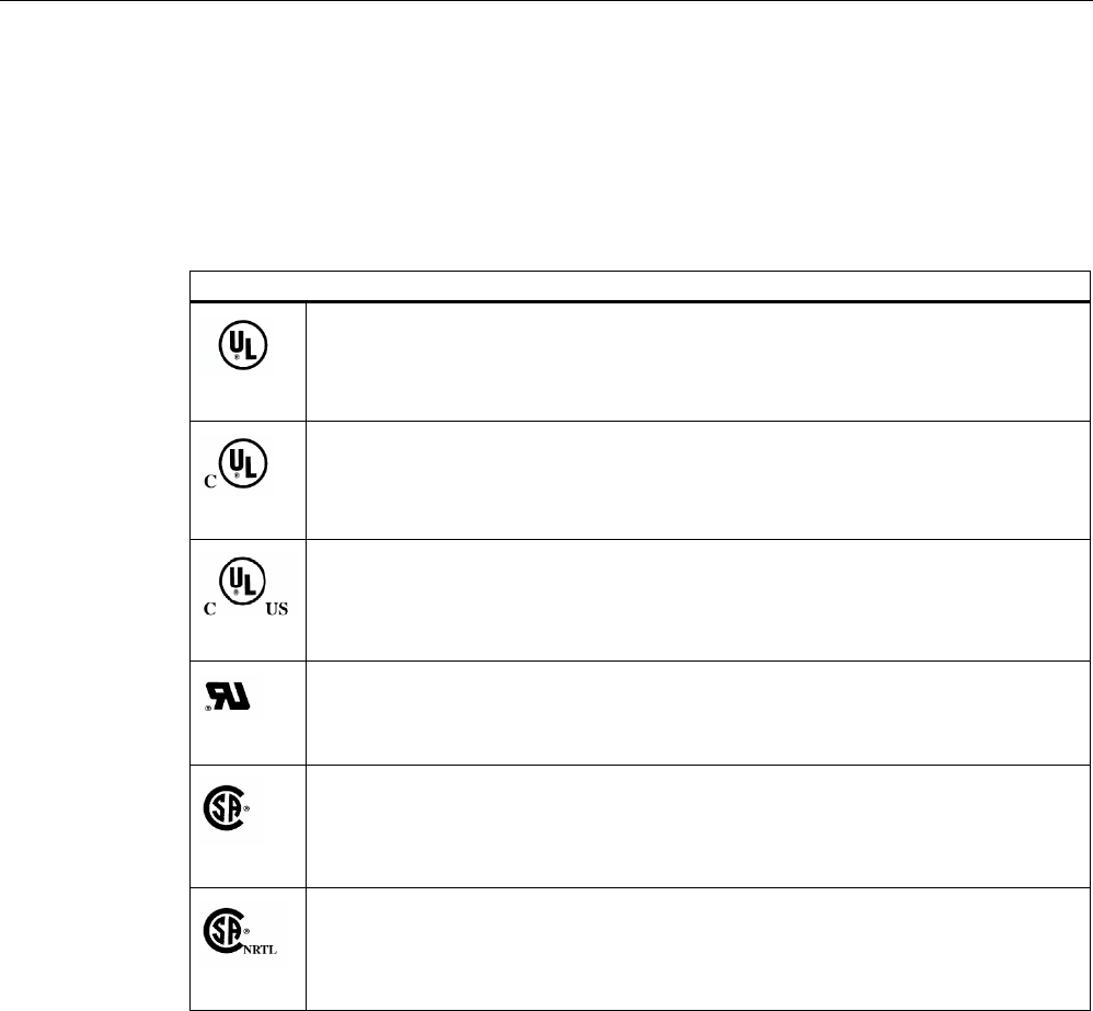
Certifications for the United States, Canada, and Australia
Safety
One of the following markings on a device is indicative of the corresponding approval:
Underwriters Laboratories (UL) per UL 60950 (I.T.E) or per UL 508 (IND.CONT.EQ)
Underwriters Laboratories (UL) according to Canadian standard C22.2 No. 60950
(I.T.E) or C22.2 No. 142 (IND.CONT.EQ)
Underwriters Laboratories (UL) according to standard UL 60950, Report E11 5352 and
Canadian standard C22.2 No. 60950 (I.T.E) or UL508 and C22.2 No. 142
(IND.CONT.EQ)
UL recognition mark
Canadian Standard Association (CSA) per Standard C22.2. No. 60950 (LR 81690) or
per C22.2 No. 142 (LR 63533)
Canadian Standard Association (CSA) per American Standard UL 60950 (LR 81690) or
per UL 508 (LR 63533)
Appendix
A.1 Certificates and Approvals
SIMATIC RF300
System Manual, Release 04/2006, J31069 D0166-U001-A2-7618 A-3
EMC
USA
Federal Communications
Commission
Radio Frequency
Interference Statement
This equipment has been tested and found to comply with the limits for a
Class A digital device, pursuant to Part 15 of the FCC Rules. These limits
are designed to provide reasonable protection against harmful
interference when the equipment is operated in a commercial
environment. This equipment generates, uses, and can radiate radio
frequency energy and, if not installed and used in accordance with the
instruction manual, may cause harmful interference to radio
communications. Operation of this equipment in a residential area is likely
to cause harmful interference in which case the user will be required to
correct the interference at his own expense.
Shielded Cables Shielded cables must be used with this equipment to maintain compliance
with FCC regulations.
Modifications Changes or modifications not expressly approved by the manufacturer
could void the user's authority to operate the equipment.
Conditions of Operations This device complies with Part 15 of the FCC Rules. Operation is subject
to the following two conditions: (1) this device may not cause harmful
interference, and (2) this device must accept any interference received,
including interference that may cause undesired operation.
CANADA
Canadian Notice This Class B digital apparatus complies with Canadian ICES-003.
Avis Canadien Cet appareil numérique de la classe b est conforme à la norme NMB-003
du Canada.
AUSTRALIA
This product meets the requirements of the AS/NZS 3548 Norm.

Appendix
A.2 Service and support
SIMATIC RF300
A-4 System Manual, Release 04/2006, J31069 D0166-U001-A2-7618
A.2 A.2 Service and support
Technical support
You can reach the technical support team for all A&D projects at
• Telephone: +49 (0) 180 5050 222
• Fax: +49 (0) 180 5050 223
Internet
• Visit our site on the Internet at:
http://www.siemens.com/automation/service&support
• You can send a support query to:
http://www.siemens.de/automation/support-request
• You can find the latest general information about our identification systems on the
Internet at:
http://www.siemens.de/simatic-sensors/rf
• The online catalog and the online ordering system is available at:
http://mall.automation.siemens.com/
A.3 A.3 Contacts
If you have any further questions on the use of our products, please contact one of our
representatives at your local Siemens office.
The addresses are found on the following pages:
• On the Internet at: http://www.siemens.com/automation/partner
• In catalog CA 01
• In Catalog FS 10 specially for factory automation sensors
A.4 A.4 Training
Training center
We offer appropriate courses to get you started. Please contact your regional Training
Center, or the central Training Center in D-90327 Nuremberg.
Telephone: +49 (911) 895-3200
http://www.sitrain.com
SIMATIC RF300
System Manual, Release 04/2006, J31069 D0166-U001-A2-7618 List of abbreviations-1
List of abbreviations
ASM
Interface module
B
Width of a transmission window
CSA
Canadian Standard Association
EMC
Electromagnetic compatibility
FB
Function Block
FC
Function
IEC
International Electrotechnical Commission
L
Length of a transmission window
MDS
Mobile data memory
OTP
One Time Programmable

List of abbreviations
SIMATIC RF300
List of abbreviations-2 System Manual, Release 04/2006, J31069 D0166-U001-A2-7618
RFID
Radio Frequency Identification Devices
Sa
Operating distance between MDS and SLG
Sg
Limit distance
SLG
Read/write device
SP
Intersection of the axes of symmetry of the MDS
Tag
See transponder
TPDR
Transponder
UHF
Ultra High Frequency
UID
Unique Identification. A serial number which identifies the transponder uniquely.
UL
Underwriter Laboratories, USA
VDE
Verband Deutscher Elektrotechniker [Association of German Electrical Engineers]
XPDR
Transponder
SIMATIC RF300
System Manual, Release 04/2006, J31069 D0166-U001-A2-7618 Glossary-1
Glossary
Active surface
Area with minimum field strength containing the transmission window, as well as the areas in
which the field strength is no longer sufficient for data exchange.
Automation system (AS)
A programmable logical controller (PLC) of the SIMATIC S7 system, comprising a central
controller, a CPU and various I/O modules.
Battery-free data storage unit
Mobile data storage units which operate without batteries. Power is supplied to the data
storage unit across an electromagnetic alternating field.
CE marking
Communauté Européenne (product mark of the European Union)
Communication modules
Communication modules are used to integrate the MOBY identification systems in SIMATIC
or SINUMERIK systems, or to connect them to PROFIBUS, PC or any other system. Once
supplied with the corresponding parameters and data, they handle data communication.
They then make the corresponding results and data available. Suitable software blocks
(FB/FC for SIMATIC; C libraries for PCs with Windows) ensure easy and fast integration in
the application.
Data transmission rate
Unit of measurement for the volume of data transmitted within a unit of time, e.g. bytes/s
Dwell time
The dwell time is the time in which the transponder dwells within the transmission window of
a read/write device. The read/write device can exchange data with the transponder during
this time.

Glossary
SIMATIC RF300
Glossary-2 System Manual, Release 04/2006, J31069 D0166-U001-A2-7618
Dynamic mode
In dynamic mode, the data carrier moves past the read/write device at a traversing rate
which depends on the configuration. Various checking mechanisms (listen-in check, CRC,
ECC, etc.) ensure error-free data transfer even under extreme environmental conditions. A
serial connection (up to 1000 m) is used to connect the read/write device directly to an
interface module, PC, or any other system.
Electromagnetic compatibility
Electromagnetic compatibility is the ability of an electrical or electronic device to operate
satisfactorily in an electromagnetic environment without affecting or interfering with the
environment over and above certain limits.
EMC Directive
Guidelines for electromagnetic compatibility This guideline relates to any electrical or
electronic equipment, plant or system containing electric or electronic components.
Equipotential bonding
Potential differences between different parts of a plant can arise due to the different design
of the plant components and different voltage levels. It is necessary to compensate for these
differences by equipotential bonding: this is done by combining the equipotential bonding
conductors of power components and non-power components on a centralized equalizing
conductor.
ESD Directive
Directive for handling ESDs.
Frequency hopping
Frequency hopping technique Automatic search for free channels.
In frequency hopping, data packets are transferred between the communication partners on
constantly changing carrier frequencies. This makes it possible to react to interference from
devices transmitting signals in the same frequency range. If an attempt to send a data
packet is unsuccessful, the packet can be transmitted again on a different carrier frequency.
Interface modules (ASM)
See communication modules
IQ-Sense interface
Simple interface on the IQ-Sense module, using a standard design for all types of sensors,
enabling integrated data exchange between the sensor and control system.

Glossary
SIMATIC RF300
System Manual, Release 04/2006, J31069 D0166-U001-A2-7618 Glossary-3
Limit distance
The limit distance is the maximum clear distance between the upper surface of the read/write
device and the transponder, at which the transmission can still function under normal
conditions.
Metal-free area
Distance/area which must be maintained between the transponder and metal in order to
prevent interference during data transfer between the transponder and read/write device.
Mobile data storage units (MDS)
See transponder
Multi-tag capability
Multi-tag capability means the ability to use several read/write devices which communicate
simultaneously with different data carriers.
Programmable logic controller (PLC)
The programmable logical controllers (PLCs) of the SIMATIC S5 systems consist of a central
controller, one or more CPUs, and various other modules (e.g. I/O modules).
Read/write devices (SLG)
See readers
Read/write distance
See transmission distance
Readers
Readers ensure fast, secure data transfer between mobile data storage units and higher-
level systems (PLCs, PCs, etc.). The data, energy included, are transmitted inductively
across an electromagnetic alternating field or by radio. This principle enables contact-free
data transmission, ensures high industrial compatibility and works reliably in the presence of
contamination or through non-metallic materials.
RFID systems
SIMATIC RF identification systems control and optimize material flow and production
sequences. They identify reliably, quickly and economically, use non-contact data
communication technology, and store data directly on the product. They are also resistant to
contamination.

Glossary
SIMATIC RF300
Glossary-4 System Manual, Release 04/2006, J31069 D0166-U001-A2-7618
Secondary fields
The strength of the secondary fields, which exist in addition to the transmission window, is
usually lower than that of the transmission window and depends on the metallic environment.
Secondary fields should not be used in configuring.
Static mode
In static mode the transponder is positioned at a fixed distance (maximum: limit distance)
exactly above the read/write device.
Telegram cycles
The transfer of a read or write command takes place in three cycles, known as message
frame cycles. 1 or 2 bytes of user data can be transferred with each command. The
acknowledgement transfer (status or read data) takes place in 3 further cycles.
TPDR
Transponder
Transmission distance
Distance between communication module (read/write device) and transponder (mobile data
storage unit)
Transmission window
Area in which reliable data exchange between transponder and read/write device is possible
due to a particular minimum field strength.
Transponder
An invented word from transmitter and responder. Transponders are used on the product,
the product carrier, the object, or its transport or packaging unit, and contain production and
manufacturing data, i.e. all application-specific data. They follow the product through
assembly lines, transfer and production lines and are used to control material flow.
Because of their wireless design, transponders can be used, if necessary, at individual work
locations or manufacturing stations, where their data can be read and updated.
SIMATIC RF300
System Manual, Release 04/2006, J31069 D0166-U001-A2-7618 Index-1
Index
8
8xIQ-Sense module
Addressing, 7-5
Configuration, 7-3
Indicators, 7-2
A
Active surface, 4-6
ANT18 and ANT30 transmission window, 4-4
Application Planning
SIMATIC RF300, 4-1
Approvals, A-1
ASM 452
Configuration, 7-10
Dimensions, 7-16
Indicators, 7-9
Operating mode, 7-11
Ordering data, 7-17
Pin assignments, 7-9
PROFIBUS address and terminating resistor, 7-13
PROFIBUS configuration, 7-11
PROFIBUS Diagnosis, 7-15
Reader connection system, 7-11
Technical data, 7-14
ASM 456
Cable, 7-28
Cable assembly by the customer, 7-29
Cable lengths, 7-28
Configurations, 7-21
Design, 7-20
Dimensional drawing with ECOFAST connection
block, 7-33
Features, 7-19
Field of application, 7-18
LED display for PROFIBUS diagnosis, 7-31
Ordering data, 7-34
PROFIBUS hardware configuration, 7-21
Setting PROFIBUS address, 7-22
Status display with LEDs, 7-31
Status LEDs, 7-30
Technical data, 7-32
Wiring ECOFAST connector plugs, 7-25
Wiring M12, 7/8" connector, 7-26
With connection block M12, 7/8, 7-33
ASM 473
Configurations, 7-37
Design and function, 7-35
Dimensions, 7-41
Features, 7-35
Hardware configuration, 7-39
Maximum configuration of an ET 200X, 7-39
Notes on operation, 7-38
Ordering data, 7-42
Pin assignments, 7-36
Reader connection system, 7-39
Technical data, 7-40
ASM 475
Assignment for connecting cable, 7-47
Cable installation, 7-47
Configuration, 7-46
Design and function, 7-43
Function of the LEDs, 7-45
Indicators, 7-45
Ordering data, 7-50
Pin assignment, 7-48
Status display with LEDs, 7-45
Technical data, 7-49
ASM 475 configuration
Centralized configuration, 7-46
Decentralized design, 7-47
ET 200M, 7-46

Index
SIMATIC RF300
Index-2 System Manual, Release 04/2006, J31069 D0166-U001-A2-7618
C
Cabinet configuration, 4-50
Cable
ASM 456 to reader, 7-28
Shielding, 4-55
Calculation example, 4-10, 4-14
CD RFIDSystemsSoftware&Communication, 9-1
Certificates, A-1
Communication time
for fault-free data transfer, 4-9
Configuration, 7-3
Connecting cable
6GT2891-0Fxxx, 7-28
Connecting the ASM 456 up to protective earth, 7-28
Contacts, A-4
Coupling paths, 4-49
D
Data volume
Relationship between speed and, 4-19, 4-20, 4-23,
4-26, 4-27
Design
Centralized, 7-3
Distributed, 7-3
Diagnostic functions
SIMATIC RF300, 8-1
Dimension drawing
Reader RF310R, 5-6, 5-11
Direction of motion
Transponder, 4-6
Dwell time
Transponder, 4-8
Dynamic mode, 4-7
Dynamic mode
Dwell time of the transponder, 4-8
E
Electromagnetic compatibility
Coupling paths, 4-49
Electromagnetic interference, 4-47
EMC Guidelines, A-3
Avoiding interference, 4-53
Basic rules, 4-45
Cabinet configuration, 4-50
Cable shielding, 4-55
Definition, 4-44
Equipotential bonding, 4-54
Overview, 4-43
Propagation of electromagnetic interference, 4-47
Equipotential bonding, 4-54
F
FC 45, 8-1
Features of ASM 452 interface module
Field of application, 7-8
Field data
Reader, 4-16
Reduction due to metal, 4-33, 4-34, 4-35, 4-37
Transponder, 4-16
Flush-mounting
of transponders and readers, 4-30
FR300
MDS STATUS, 8-4
I
Inductive alternating field, 4-2
Installation
Several readers, 4-31
Installation guidelines, 4-29
Interference sources
Electromagnetic, 4-48
IQ-Sense interface
Pin assignment, 7-4
L
LEDs
For MOBY, 7-36
for PROFIBUS DP, 7-36
M
MDS STATUS, 8-1
Memory configuration of the RF300 tags, 6-18
Metal-free area
Reader RF310R, 5-3, 5-8, 5-13
Transponder RF320T, 6-2
Transponder RF340T, 6-6, 6-10, 6-14
Minimum distance
Reader to reader, 4-18
Transponder to transponder, 4-18
O
Ordering data
RF310R with IQ-Sense, 5-5

Index
SIMATIC RF300
System Manual, Release 04/2006, J31069 D0166-U001-A2-7618 Index-3
P
PROFIBUS cable
Stripped lengths, 7-41
PROFIBUS Diagnosis
ASM 452, 7-15
R
Read/write distance, 4-2
Reader and ANT1 transmission window, 4-2
Reader RF310R, 5-2, 5-7, 5-12, 5-17
Dimension drawing, 5-6, 5-11
Display elements, 5-2, 5-7, 5-12, 5-17
Features, 5-2, 5-7, 5-12, 5-17
Metal-free area, 5-3, 5-8, 5-13
Minimum distance, 5-3, 5-8
Pin assignment of IQ-Sense interface, 7-4
Readers, 5-1
Mounting, 4-31
Reducing interference due to metal, 4-29
Reduction of field data, 4-33, 4-34, 4-35, 4-37
Resistance to chemicals
Transponder, 4-38
RF300
SLG STATUS, 8-2, 8-3
RFID systems
Overview, 3-1
S
Safety information/instructions, 2-1
Secondary fields, 4-5
Service, A-4
Shielding, 4-55
SIMATIC RF300
Diagnostic functions, 8-1
SLG STATUS, 8-1
Static mode, 4-7
Static mode
Dwell time of the transponder, 4-8
Support, A-4
System components
Overview, 3-4
System overview
RFID systems, 3-1
Systems
RFID, 3-1
T
Technical data
ASM 456, 7-32
ASM 475, 7-49
Transponder RF320T, 6-3, 6-7
Transponder RF340T, 6-7
Transponder RF350T, 6-11, 6-16
Transponder RF360T, 6-16
Time constants, 4-9
Tolerance of pallet side transport, 4-10, 4-14
Tolerance of pallet transport height, 4-10, 4-14
Tracking
Tolerance, 4-5
Tracking tolerances, 4-5
Training center, A-4
Transmission window
Impact of metal, 4-33, 4-37
Width, 4-5
Transponder, 6-1
Active surface, 4-6
Directions of motion, 4-6
Dwell time, 4-8
Mounting on metal, 4-32
Resistance to chemicals, 4-38
Transponder RF320T, 6-4
Features, 6-1
Metal-free area, 6-2
Technical data, 6-3
Transponder RF340T
Features, 6-5, 6-13
Metal-free area, 6-6, 6-10, 6-14
Technical data, 6-7
Transponder RF350T
Features, 6-9
Technical data, 6-11
Transponder RF360T
Technical data, 6-16
Transponder speed, 4-19, 4-20, 4-23, 4-26
U
User data
Calculation of maximum amount of, 4-9

Index
SIMATIC RF300
Index-4 System Manual, Release 04/2006, J31069 D0166-U001-A2-7618

Siemens AG
Automation and Drives
Factory Automation Sensors
Postfach 4848
90327 NUERNBERG
Federal Republic of Germany
www.siemens.com/simatic-sensors