Siemens RF380R01 Tag Reader User Manual SIMATIC Sensors RFID systems SIMATIC RF300
Siemens AG Tag Reader SIMATIC Sensors RFID systems SIMATIC RF300
UserManual.wiki
>
Siemens
>
RF380R01 User Manual
User Manual
Navigation menu
Upload a User Manual
Namespaces
Wiki Guide
HTML
PDF
Info
Views
User Manual
Discussion / Help
Navigation
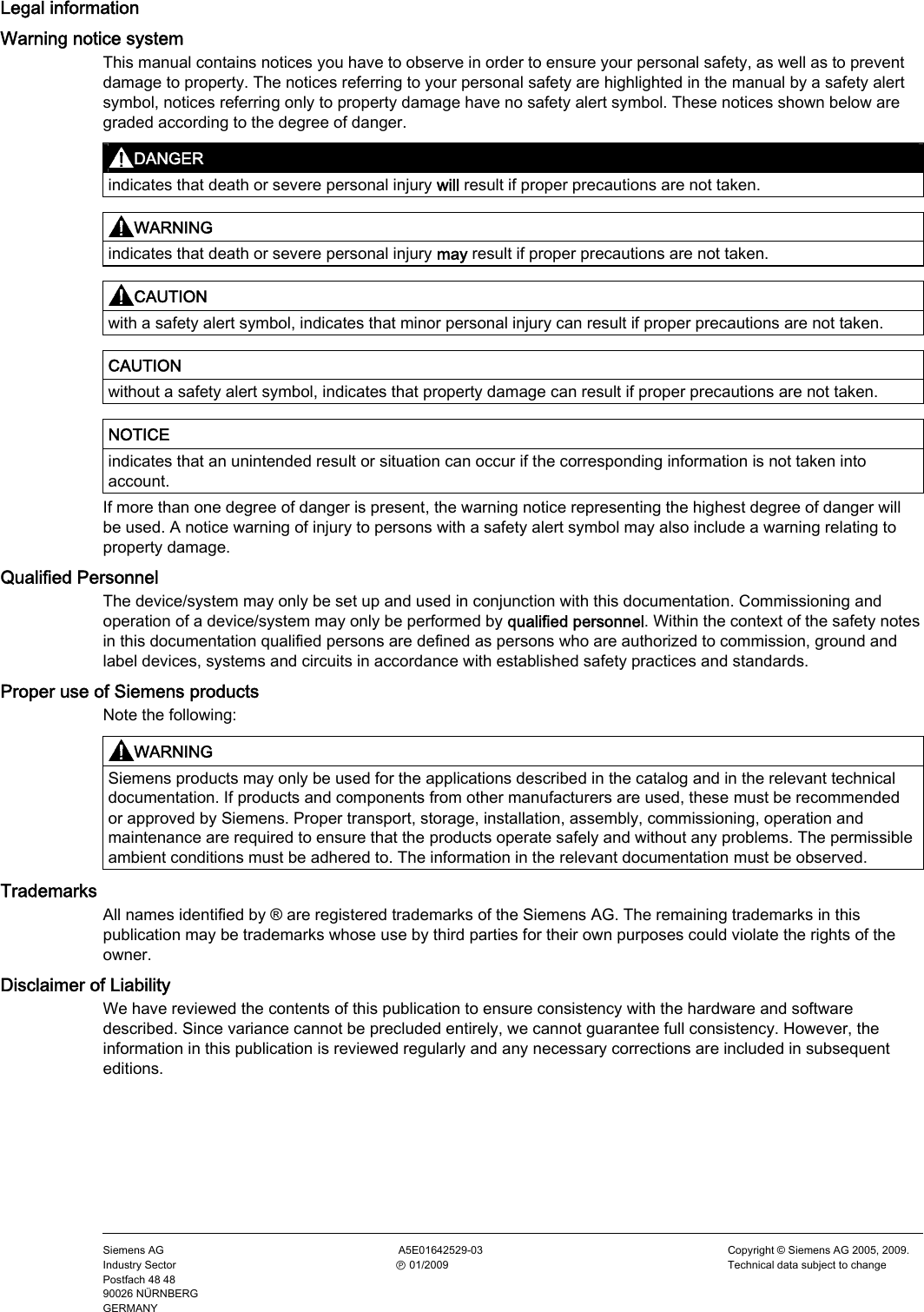
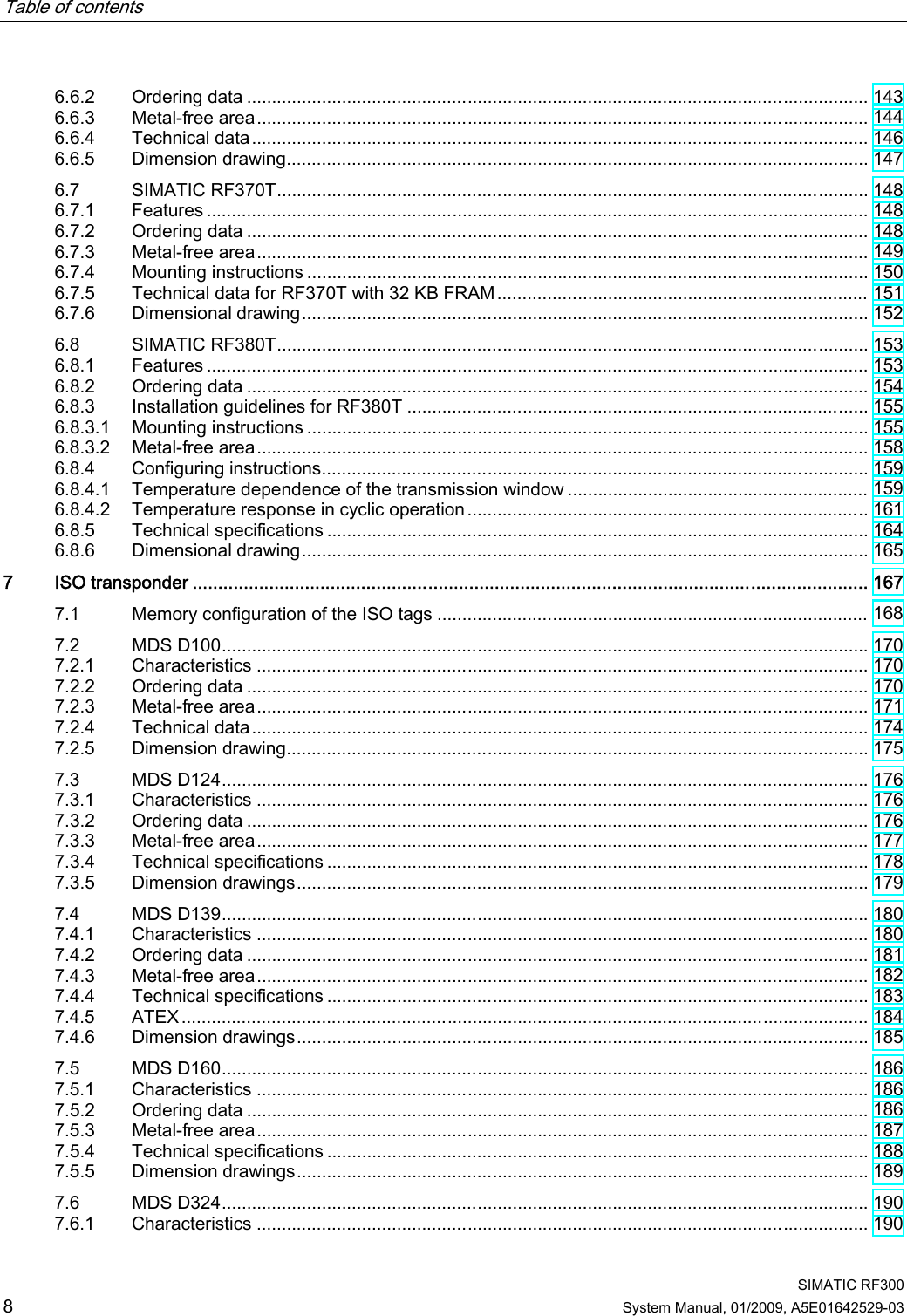
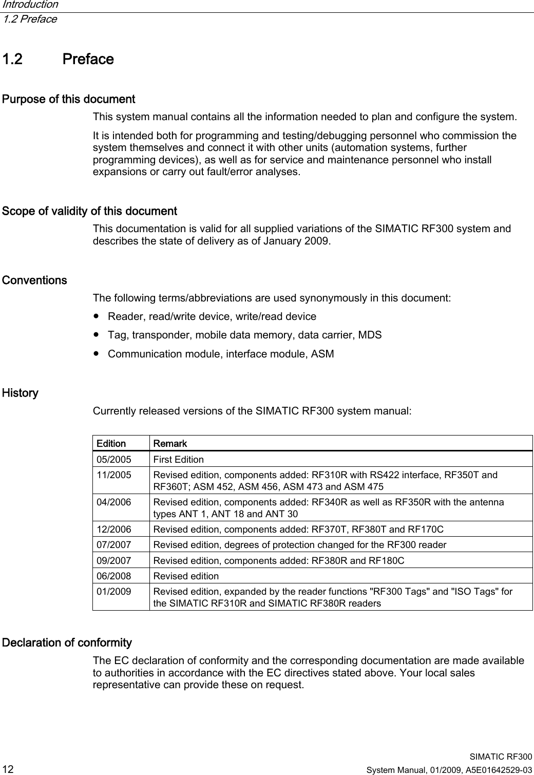


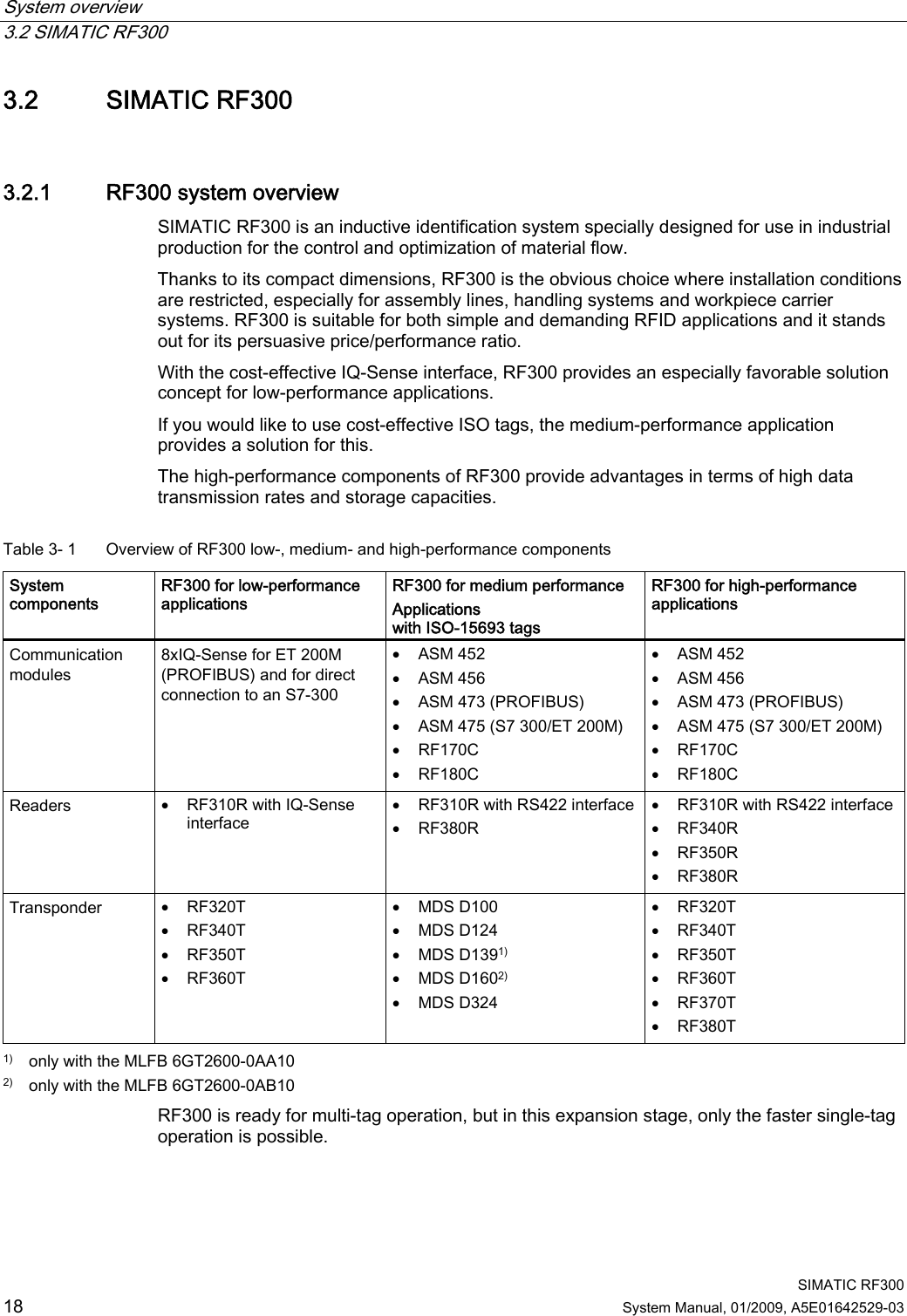
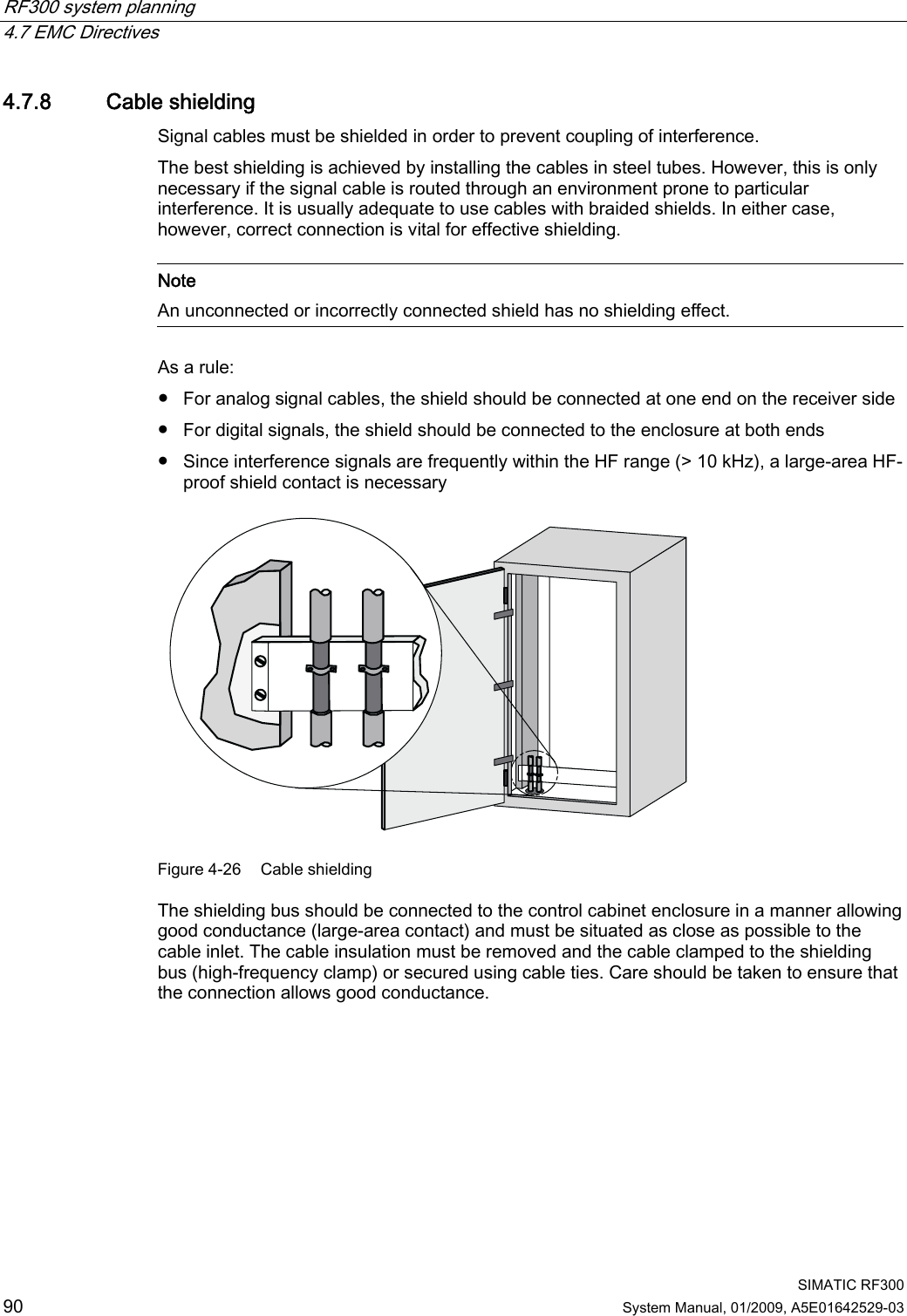
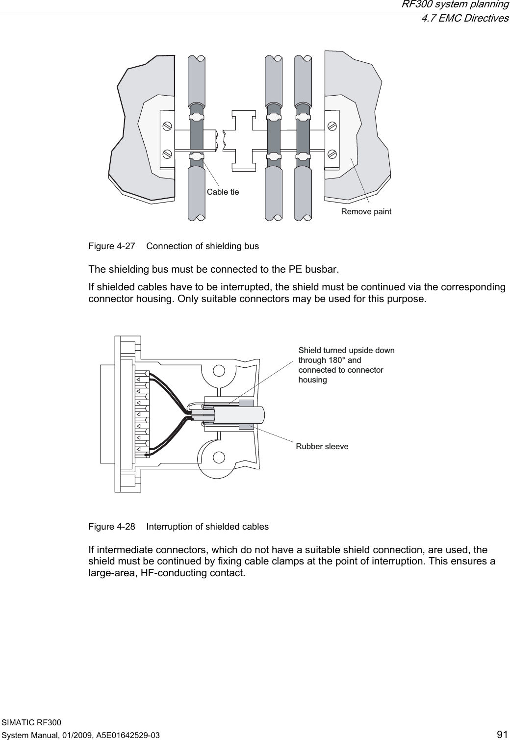
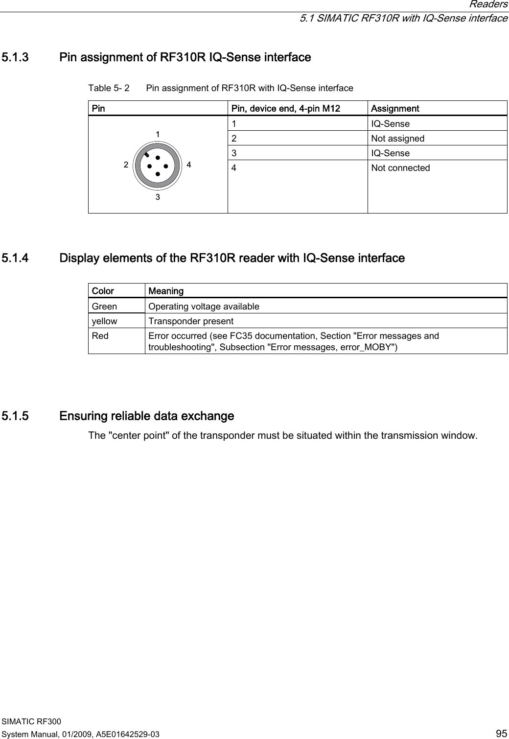
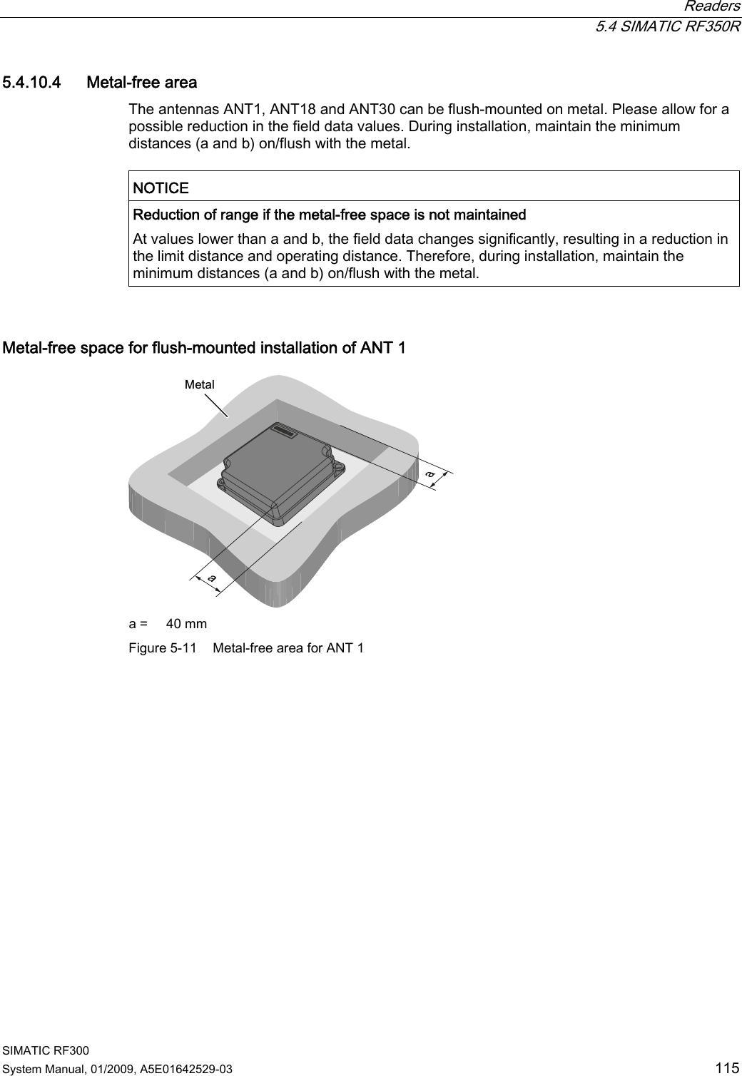
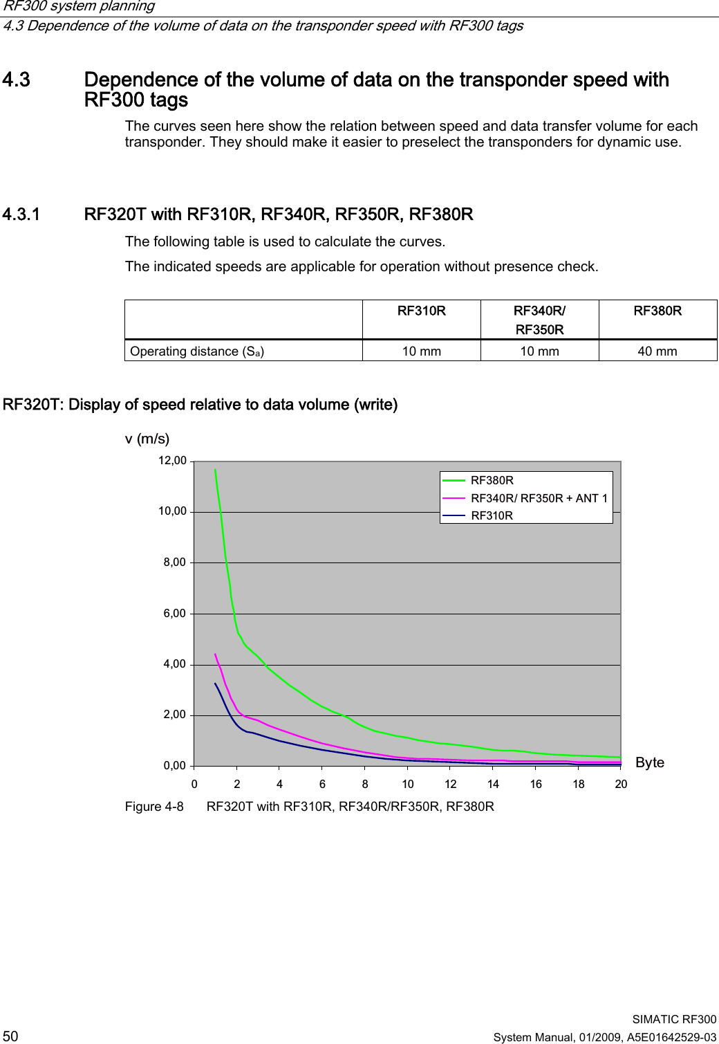
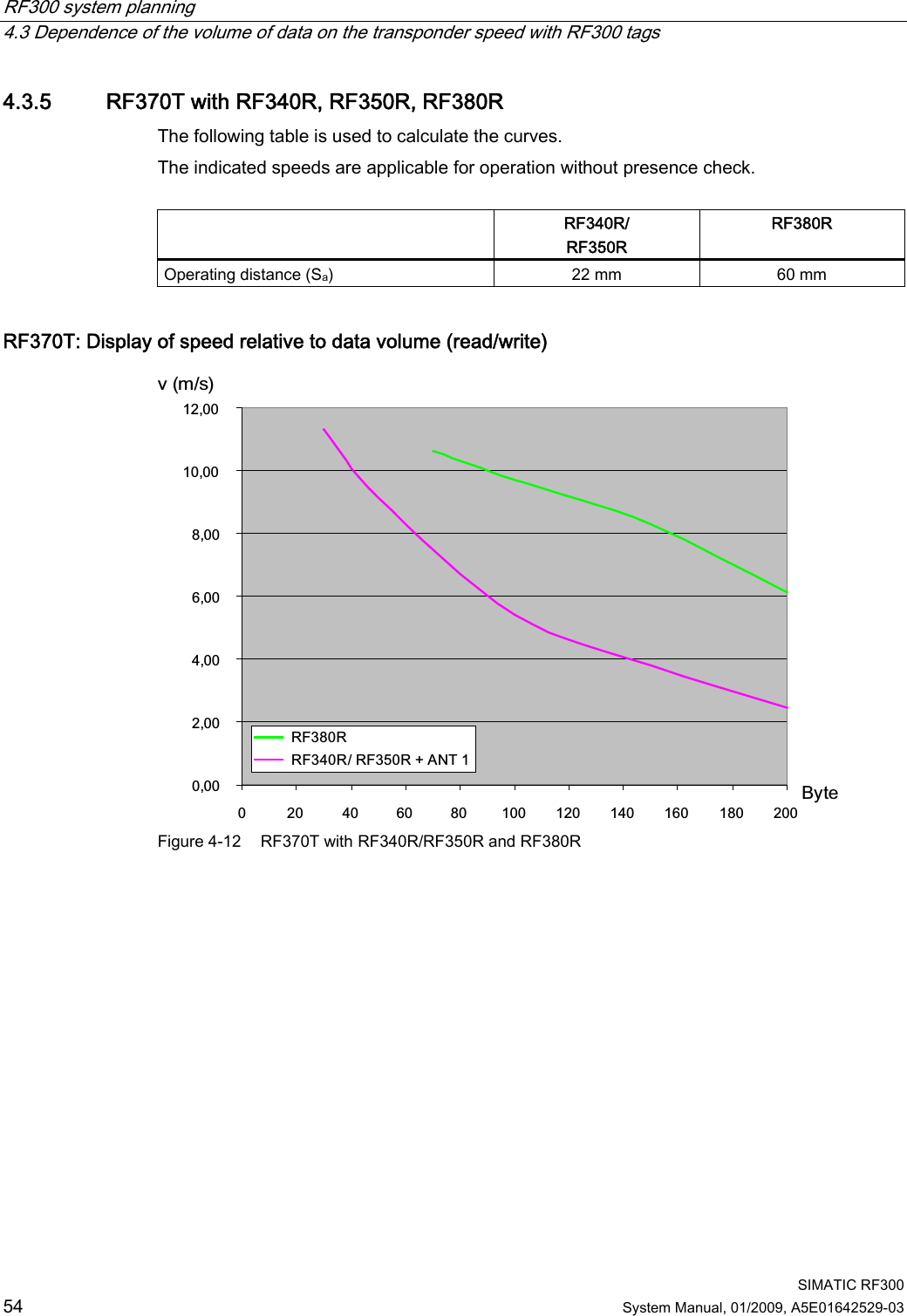
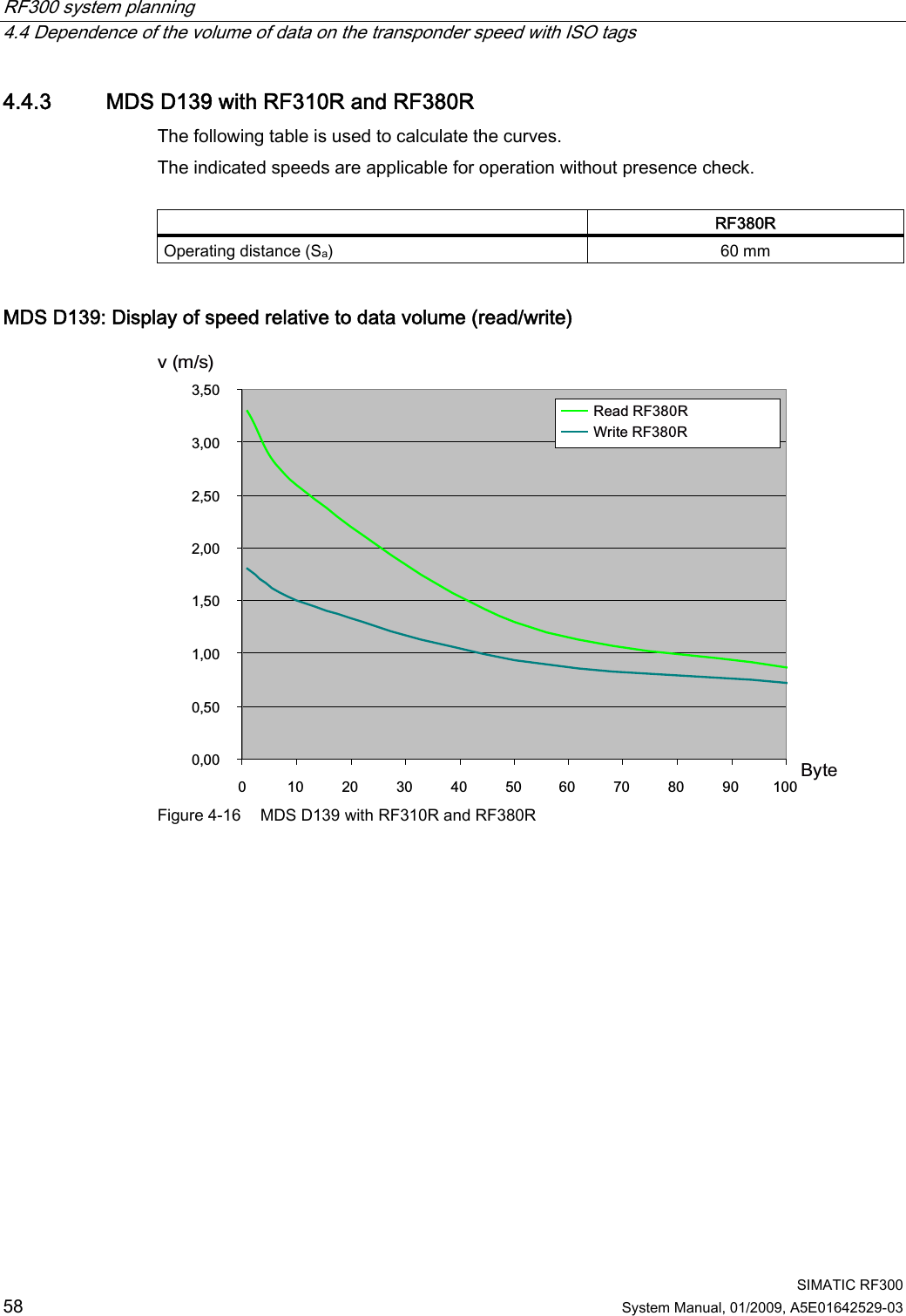
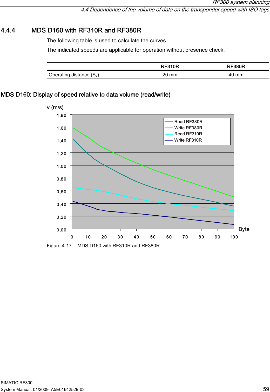
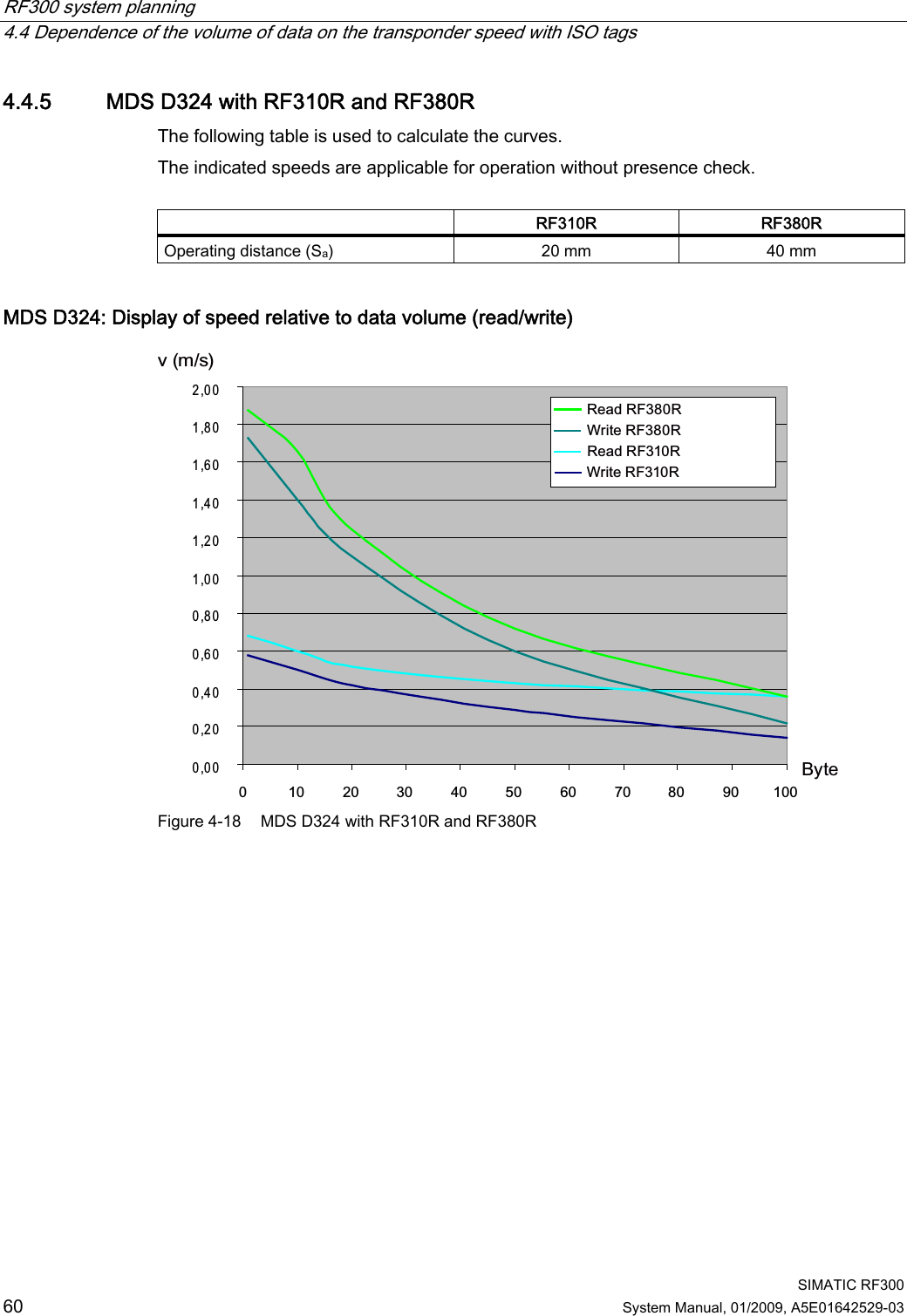
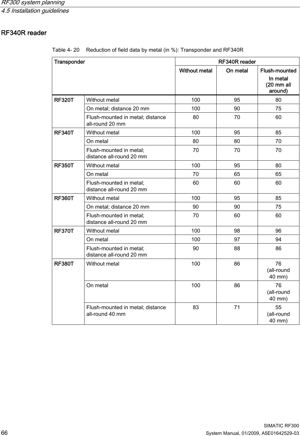
![System overview 3.2 SIMATIC RF300 SIMATIC RF300 20 System Manual, 01/2009, A5E01642529-03 RF300 system components for low- and high-performance applications 7UDQVSRQGHU 5HDGHU &RPPXQLFDWLRQPRGXOHV3RZHUDQGGDWDWUDQVPLVVLRQ0+]6HULDODV\QFKURQRXVLQWHUIDFH56 56563&LQWHUIDFH7KLUGSDUW\3/&$60IRU6,0$7,&65)&IRU(7SUR$60IRU(7;$60IRU352),%86'39$60bIRU352),%86'3'395)&IRU352),1(7,2,46HQVHLQWHUIDFH[,46HQVHIRU(702Q65)5,46HQVH5)7 5)7 5)7 5)7 5)7 5)75)55)0 5)55)55)5 Figure 3-1 System overview low- and high-performance Table 3- 2 Reader-tag combination options for low- and high-performance applications Tags/ MDS RF310R (IQ-Sense) RF310R (RS422) RF340R RF350R with ANT 1 RF350R with ANT 18 RF350R with ANT 30 RF380R RF320T ✓ ✓ ✓ ✓ ✓ ✓ ✓ RF340T ✓ ✓ ✓ ✓ ✓ ✓ ✓ RF350T ✓ ✓ ✓ ✓ -- ✓ ✓ RF360T ✓ ✓ ✓ ✓ -- -- ✓ RF370T ○ ○ ✓ ✓ -- -- ✓ RF380T ○ ○ ✓ ✓ -- -- ✓ ✓ Combination possible -- Combination not approved ○ Combination possible, but not recommended](https://usermanual.wiki/Siemens/RF380R01/User-Guide-1144704-Page-20.png)
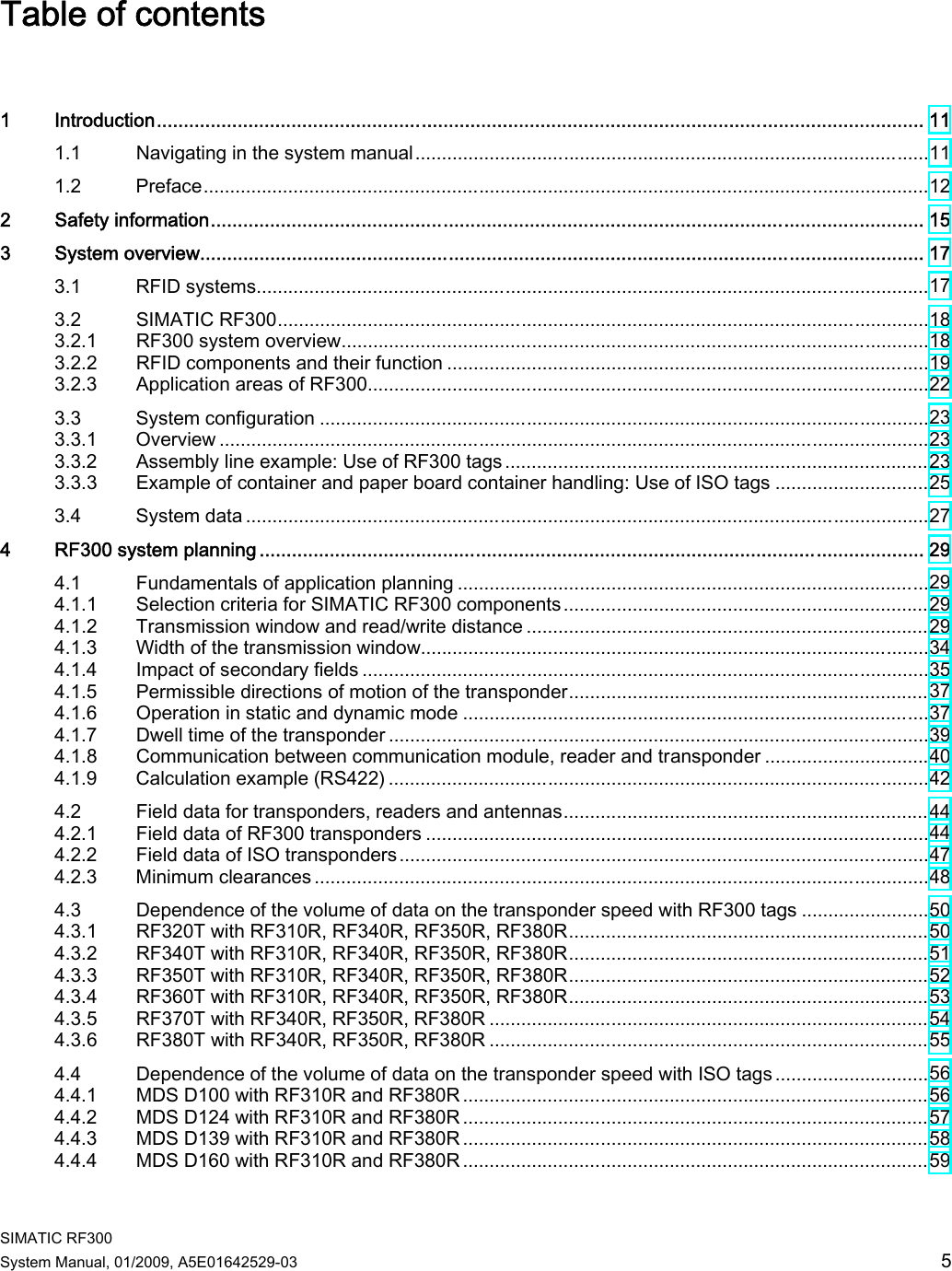
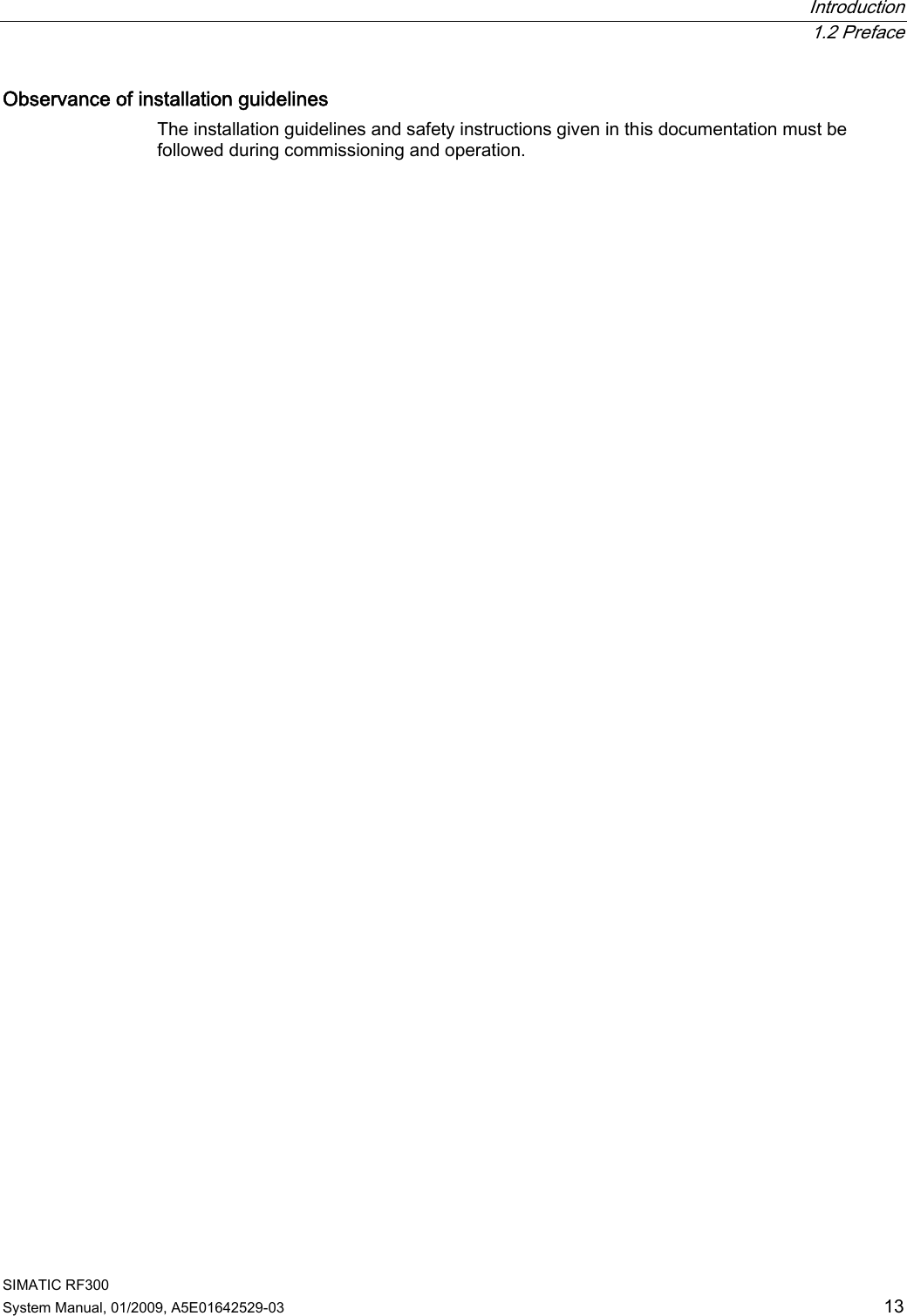
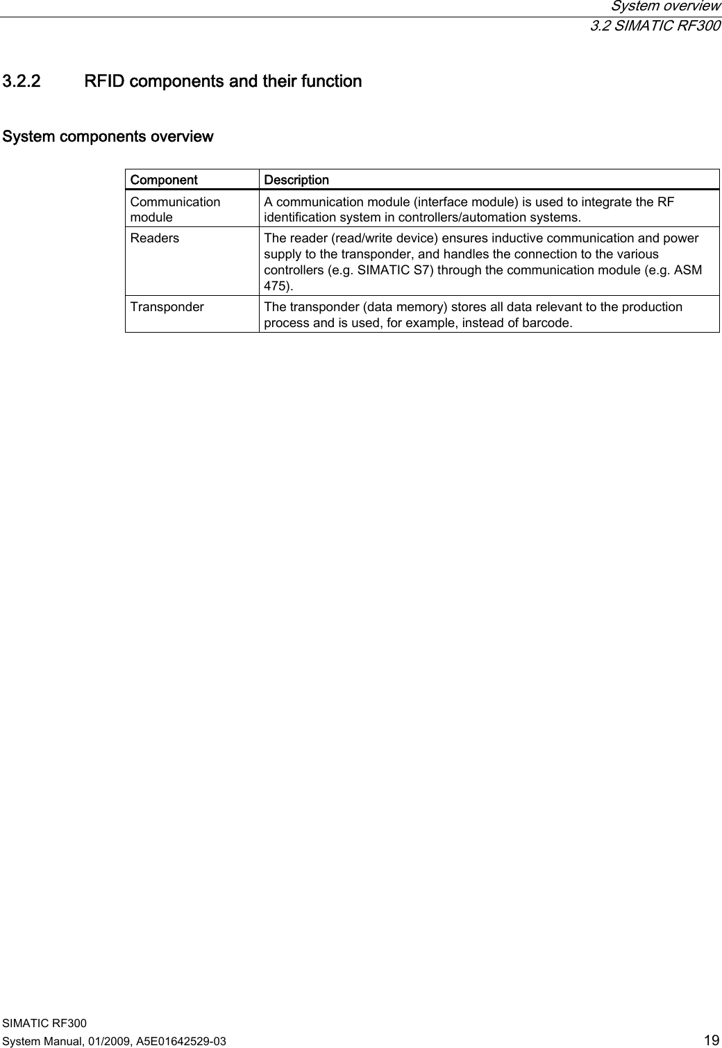
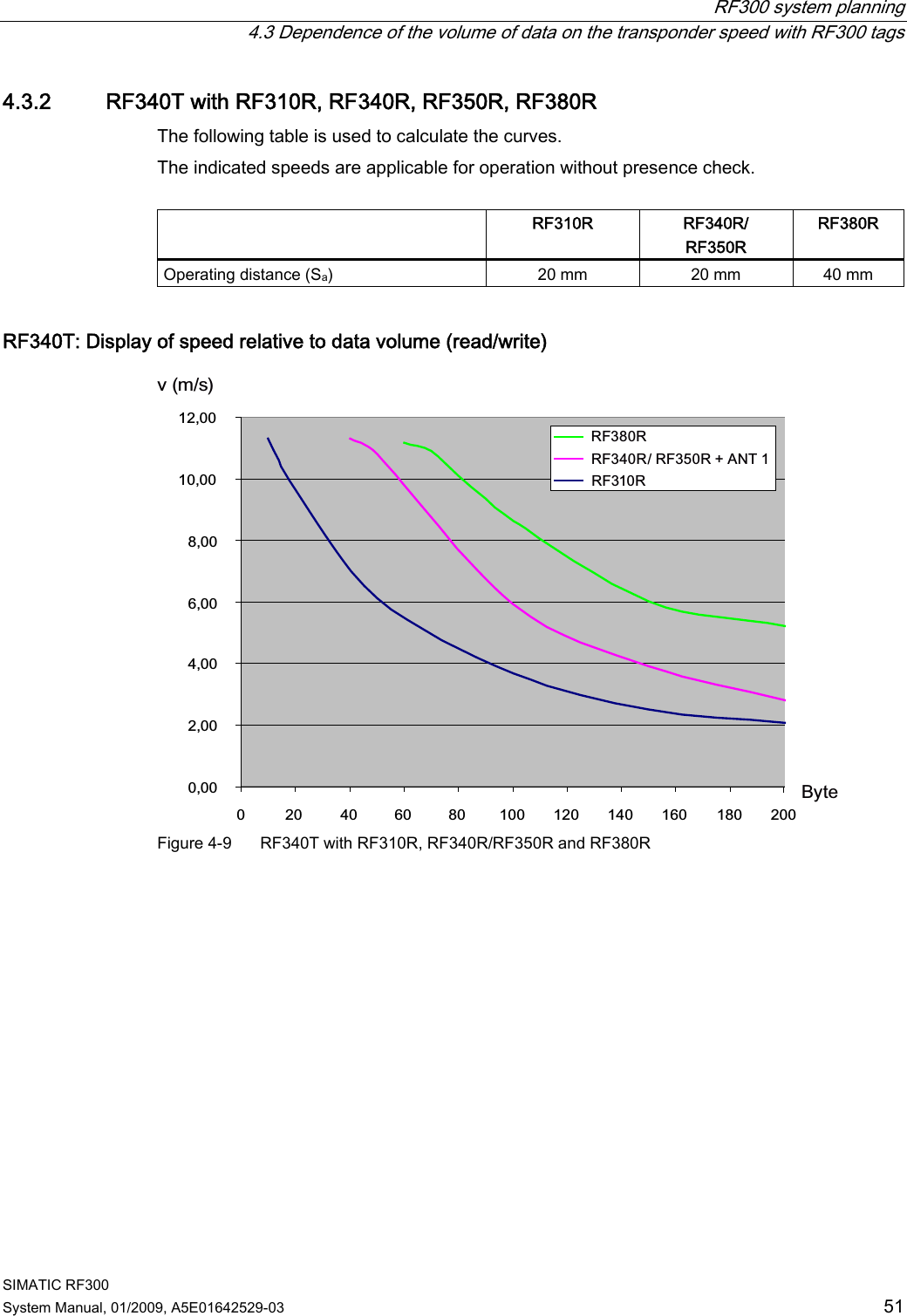
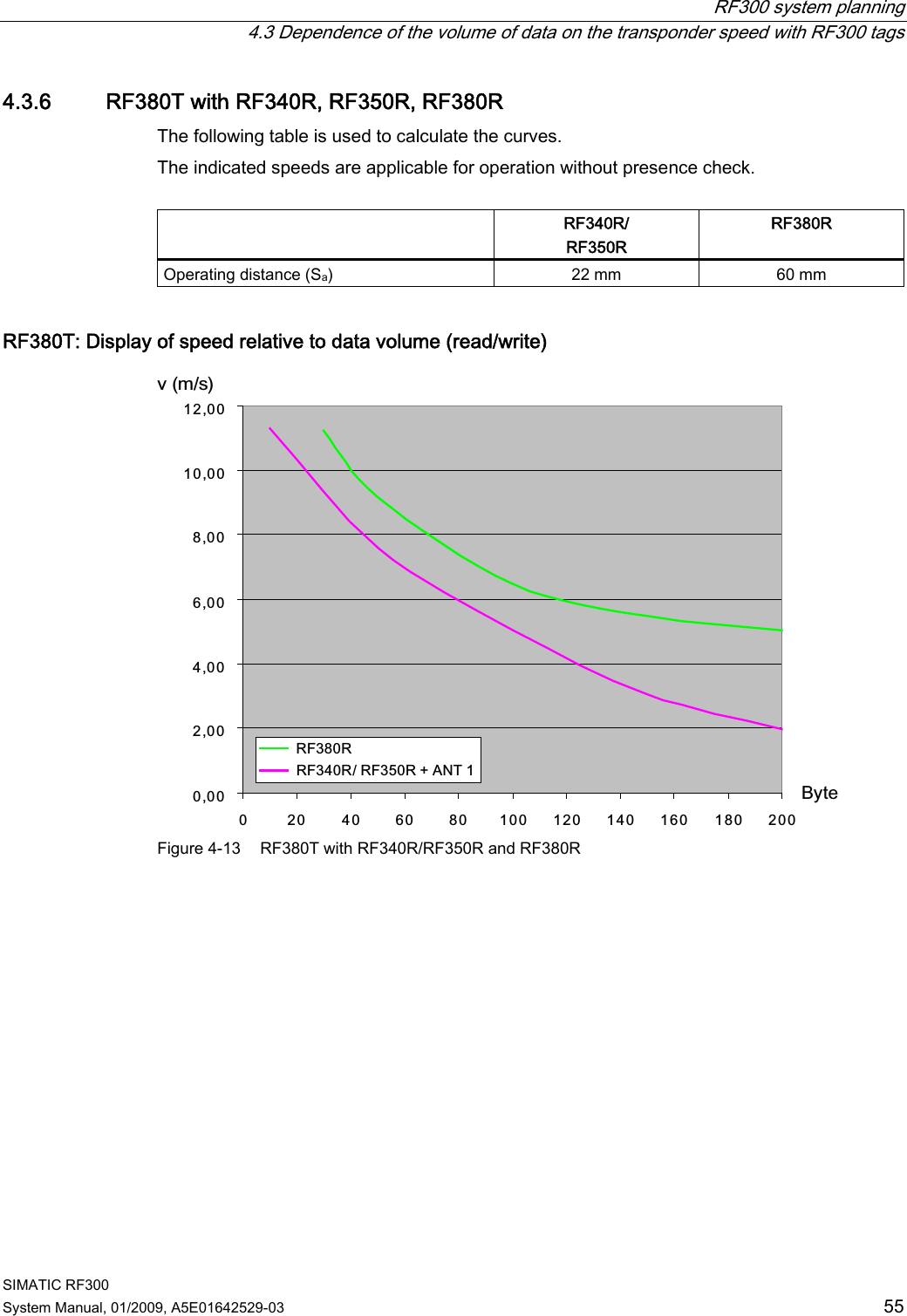
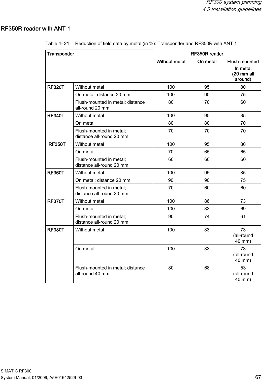
![System overview 3.2 SIMATIC RF300 SIMATIC RF300 System Manual, 01/2009, A5E01642529-03 21 RF300 system components for medium-performance applications 5HDGHU &RPPXQLFDWLRQPRGXOHV3RZHUDQGGDWDWUDQVPLVVLRQ0+]6HULDODV\QFKURQRXVLQWHUIDFH56 56563&LQWHUIDFH7KLUGSDUW\3/&$60IRU6,0$7,&65)&IRU(7SUR$60IRU(7;$60IRU352),%86'39$60bIRU352),%86'3'395)&IRU352),1(7,27UDQVSRQGHU0'6'0'6' 0'6' 0'6' 0'6'5)0 5)55)5 Figure 3-2 System overview medium-performance Table 3- 3 Reader-tag combination options for medium-performance applications Tags/ MDS RF310R (IQ-Sense) RF310R (RS422) RF340R RF350R with ANT 1 RF350R with ANT 18 RF350R with ANT 30 RF380R MDS D100 -- ✓ -- -- -- -- ✓ MDS D124 -- ✓ -- -- -- -- ✓ MDS D139 -- ○ -- -- -- -- ✓ MDS D160 -- ✓ -- -- -- -- ✓ MDS D324 -- ✓ -- -- -- -- ✓ ✓ Combination possible -- Combination not approved ○ Combination possible, but not recommended](https://usermanual.wiki/Siemens/RF380R01/User-Guide-1144704-Page-21.png)
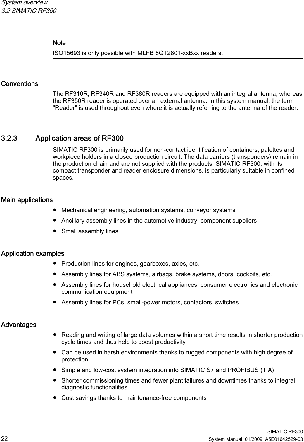

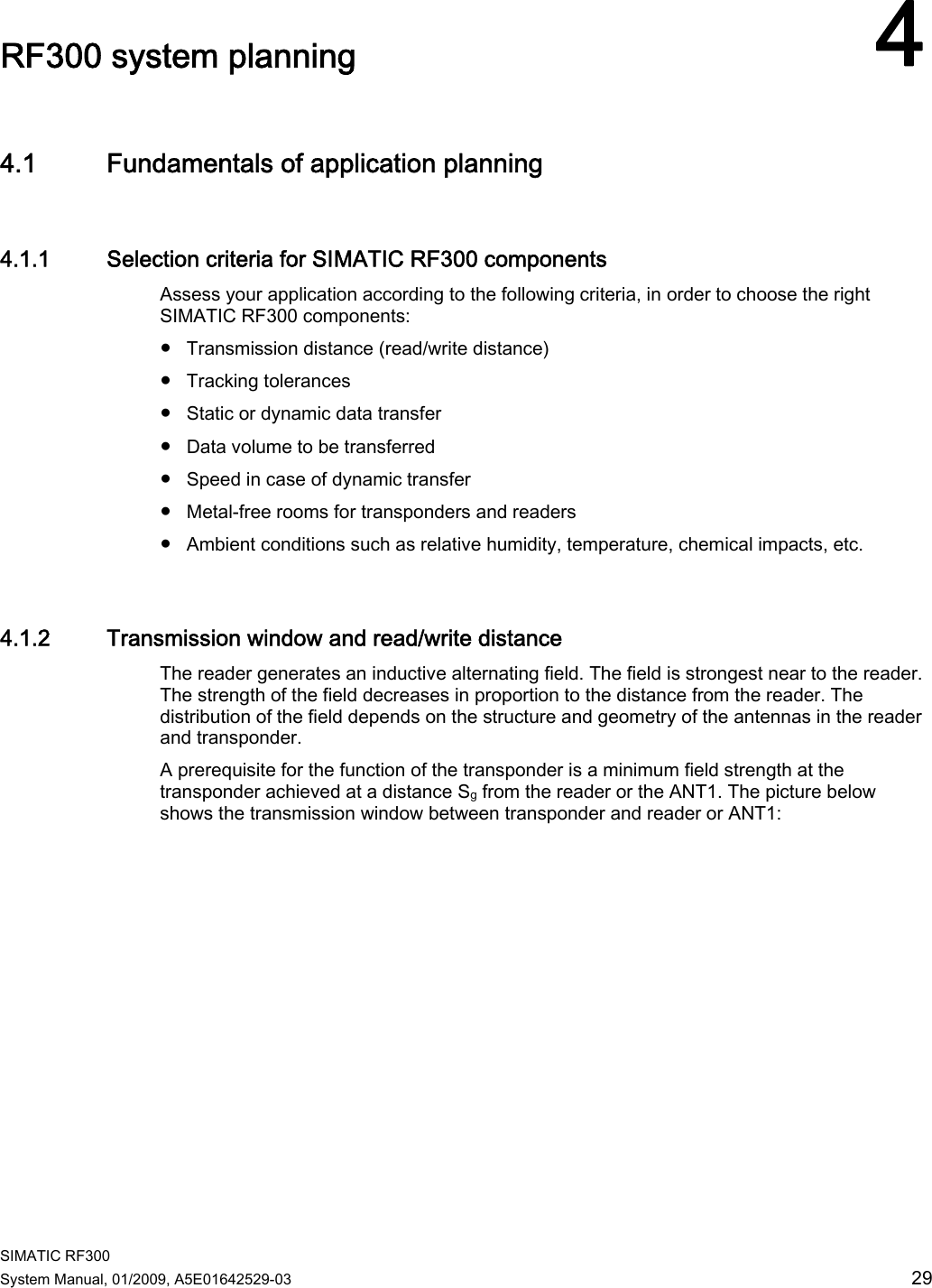
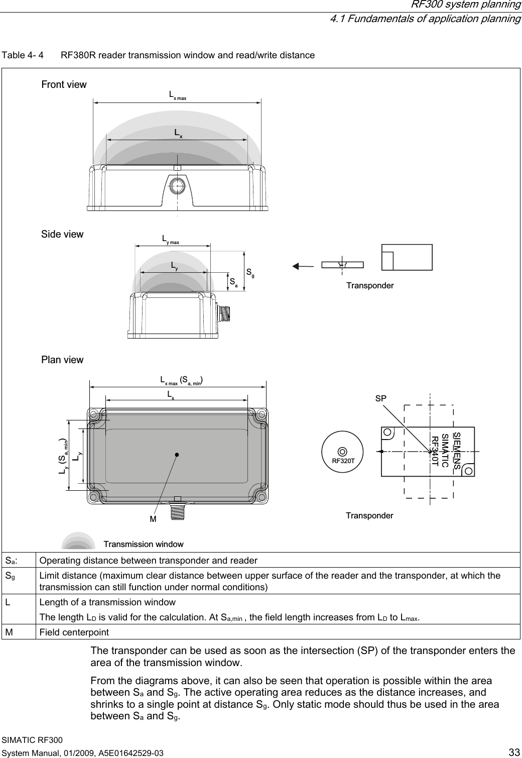
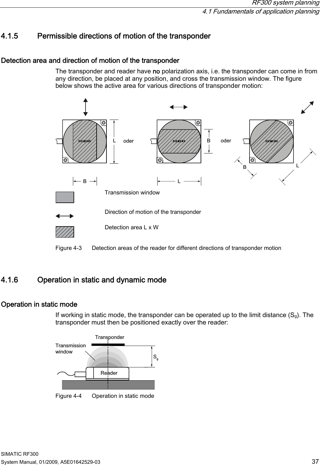
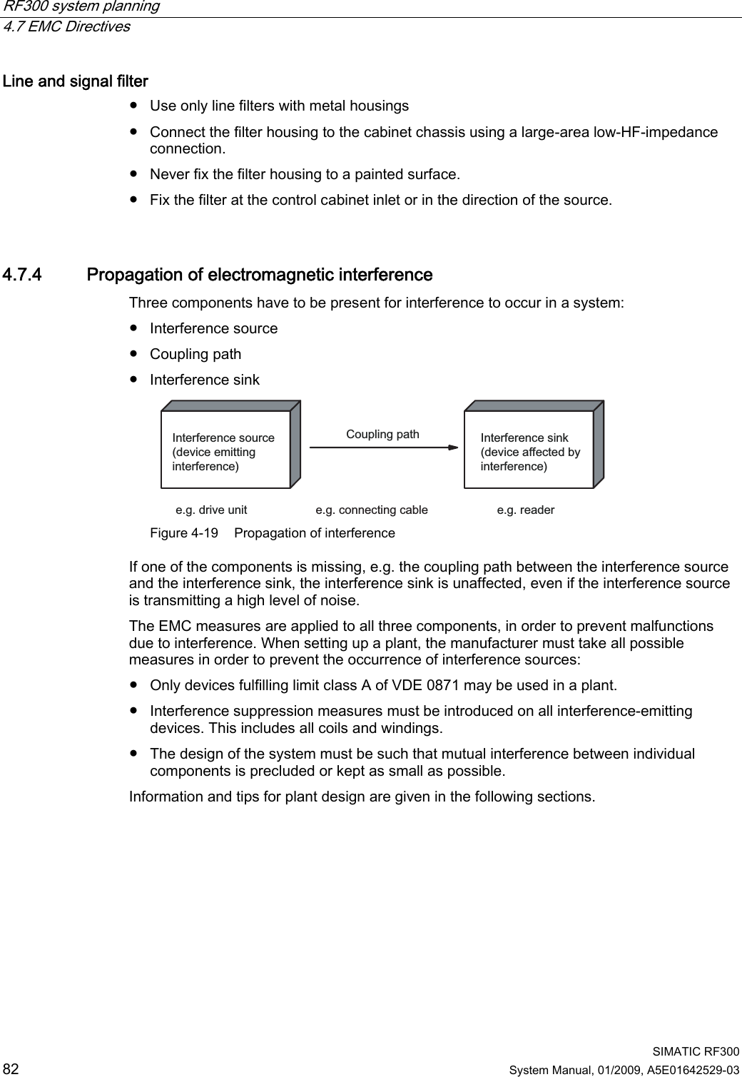
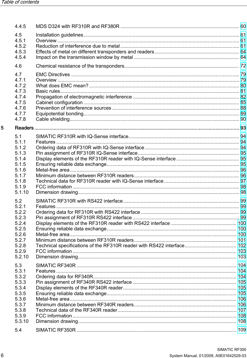
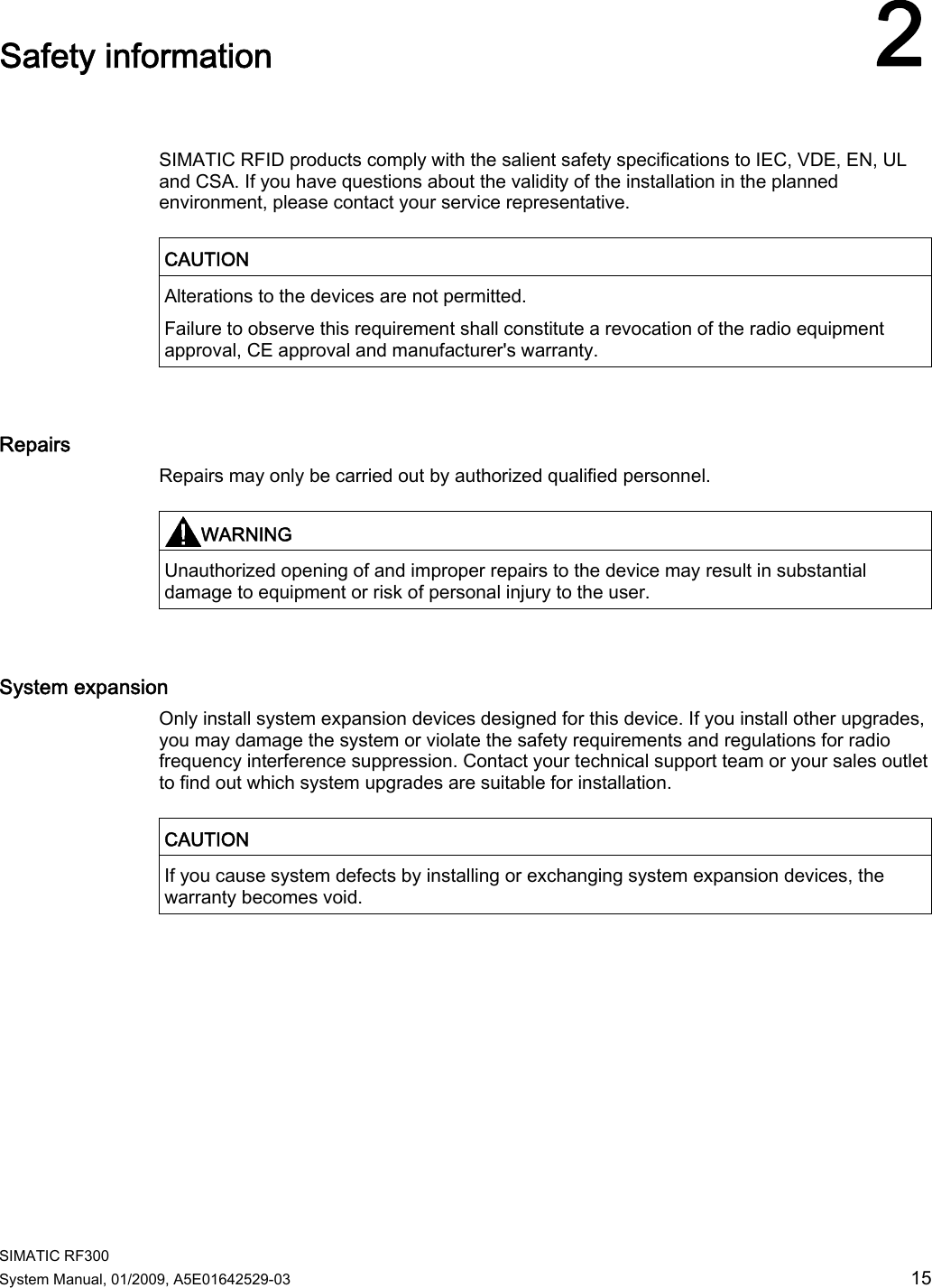
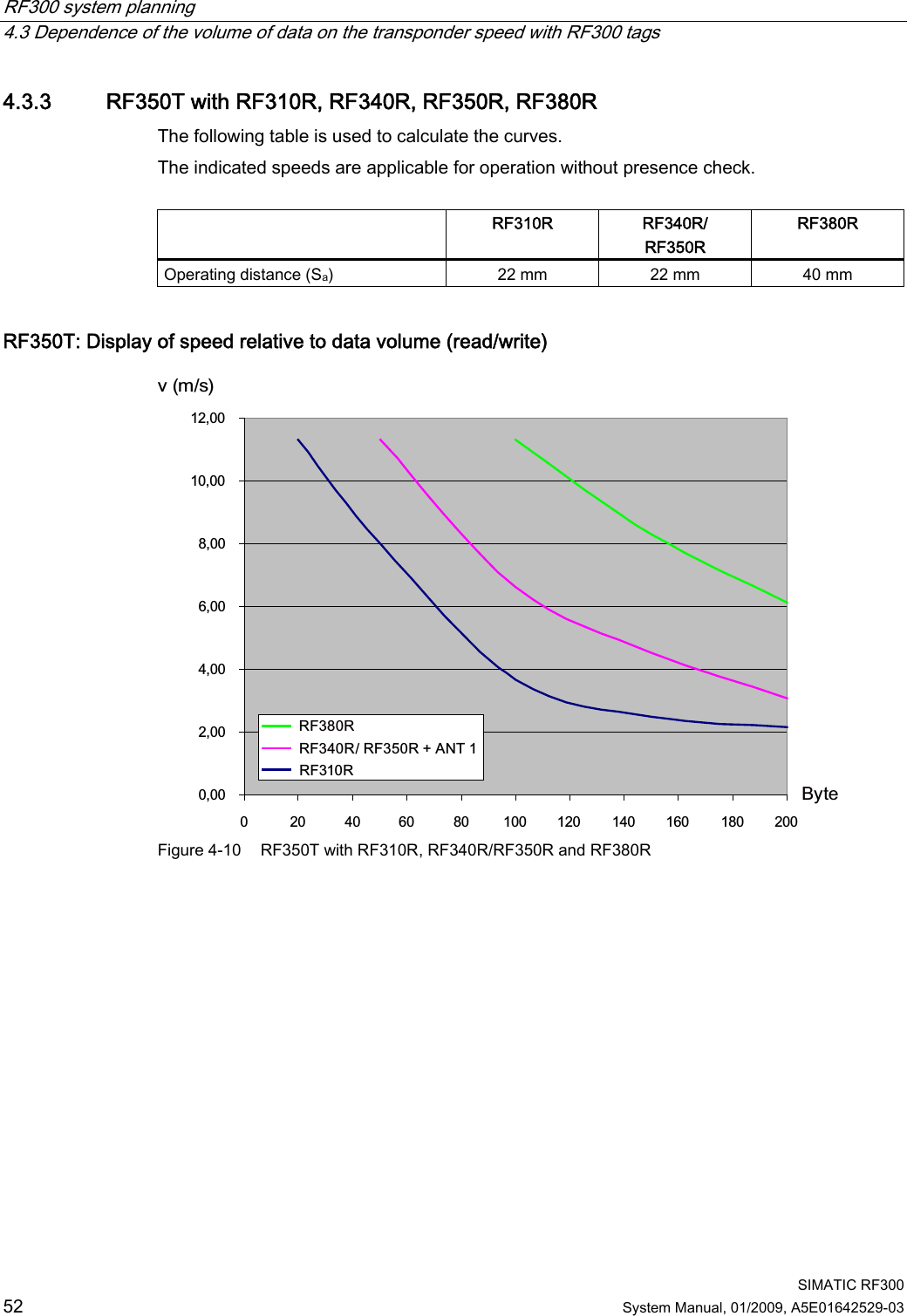
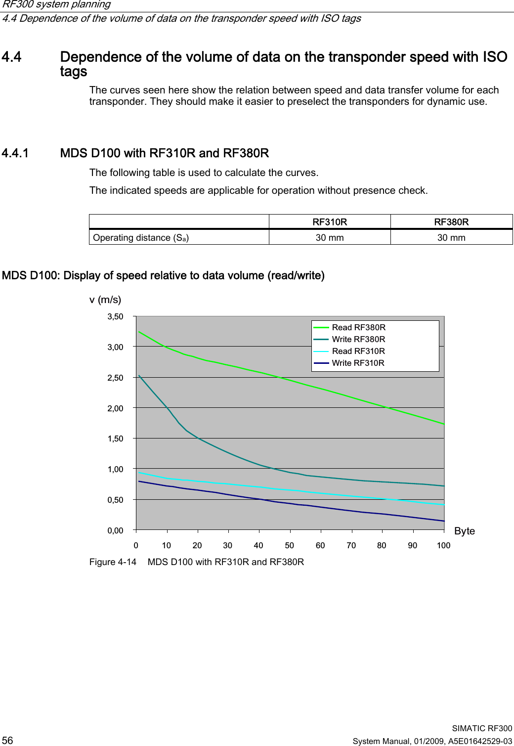
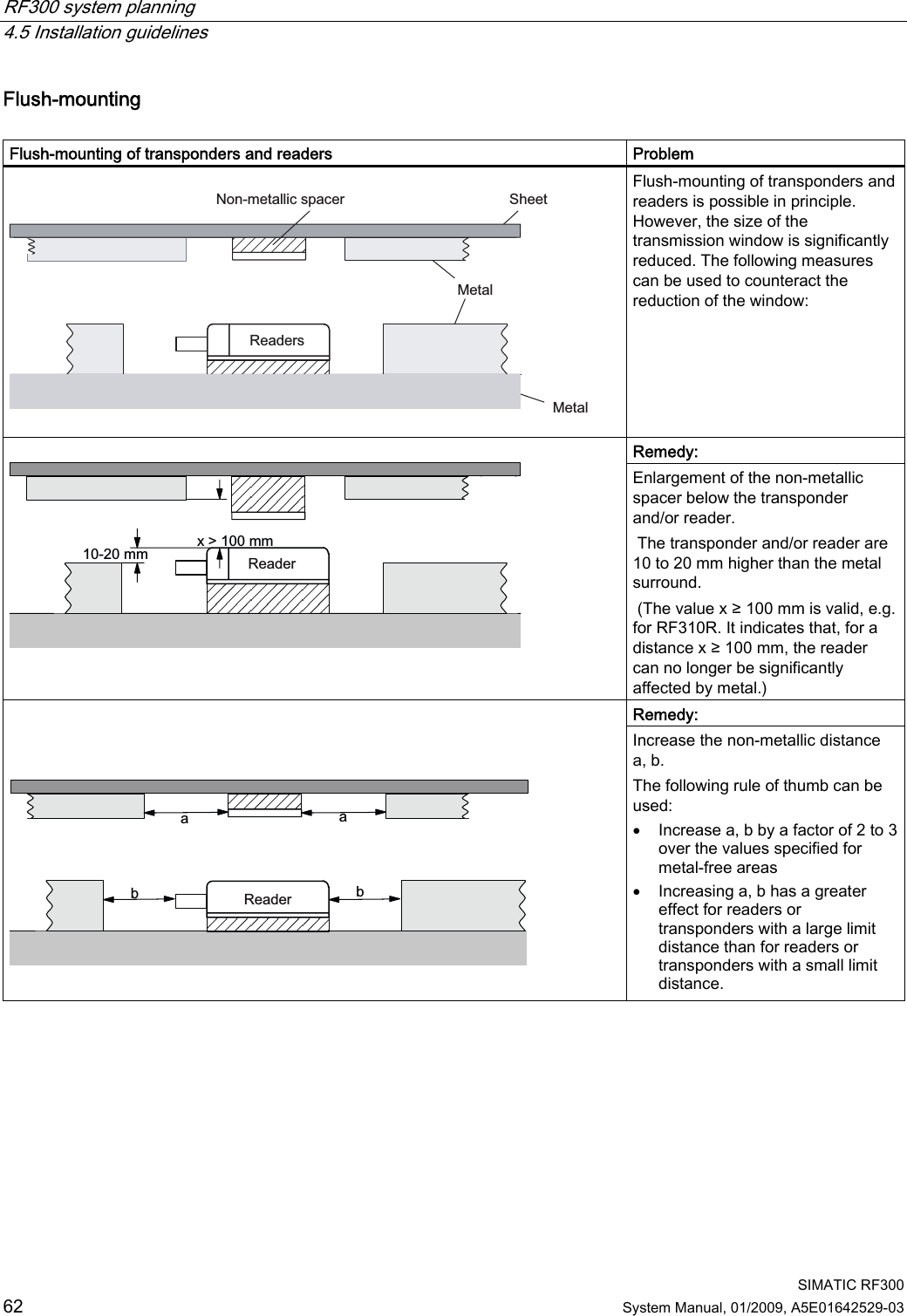
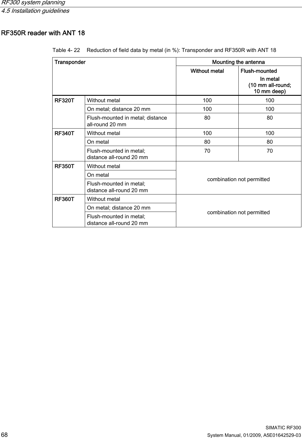
![RF300 system planning 4.1 Fundamentals of application planning SIMATIC RF300 38 System Manual, 01/2009, A5E01642529-03 Operation in dynamic mode When working in dynamic mode, the transponder moves past the reader. The transponder can be used as soon as the intersection (SP) of the transponder enters the circle of the transmission window. In dynamic mode, the operating distance (Sa) is of primary importance. [Operating distances, see Chapter Field data for transponders, readers and antennas (Page 44)] 7UDQVPLVVLRQZLQGRZ7UDQVSRQGHU7UDQVSRQGHU3ODQYLHZ6363 Figure 4-5 Operation in dynamic mode](https://usermanual.wiki/Siemens/RF380R01/User-Guide-1144704-Page-38.png)
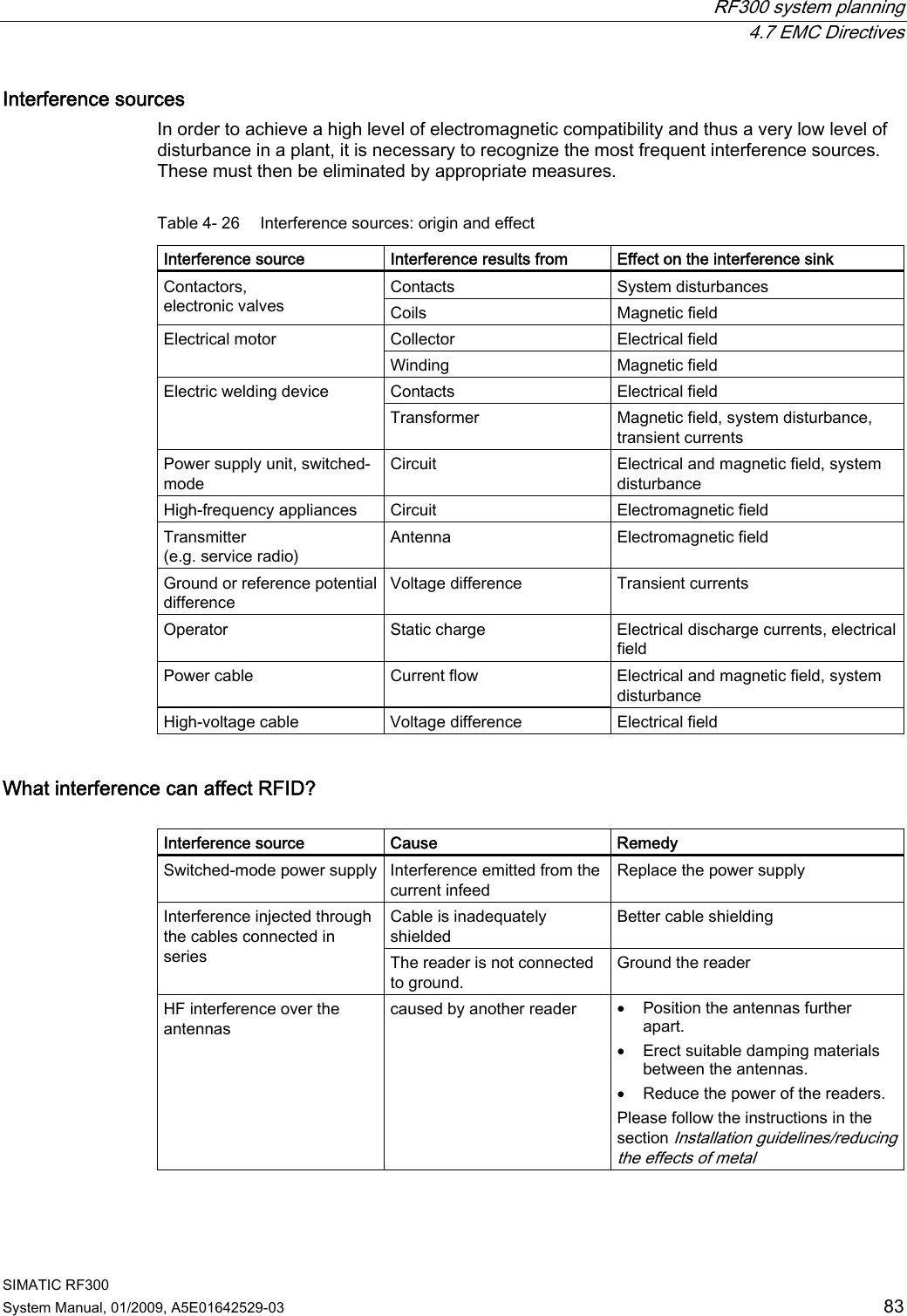
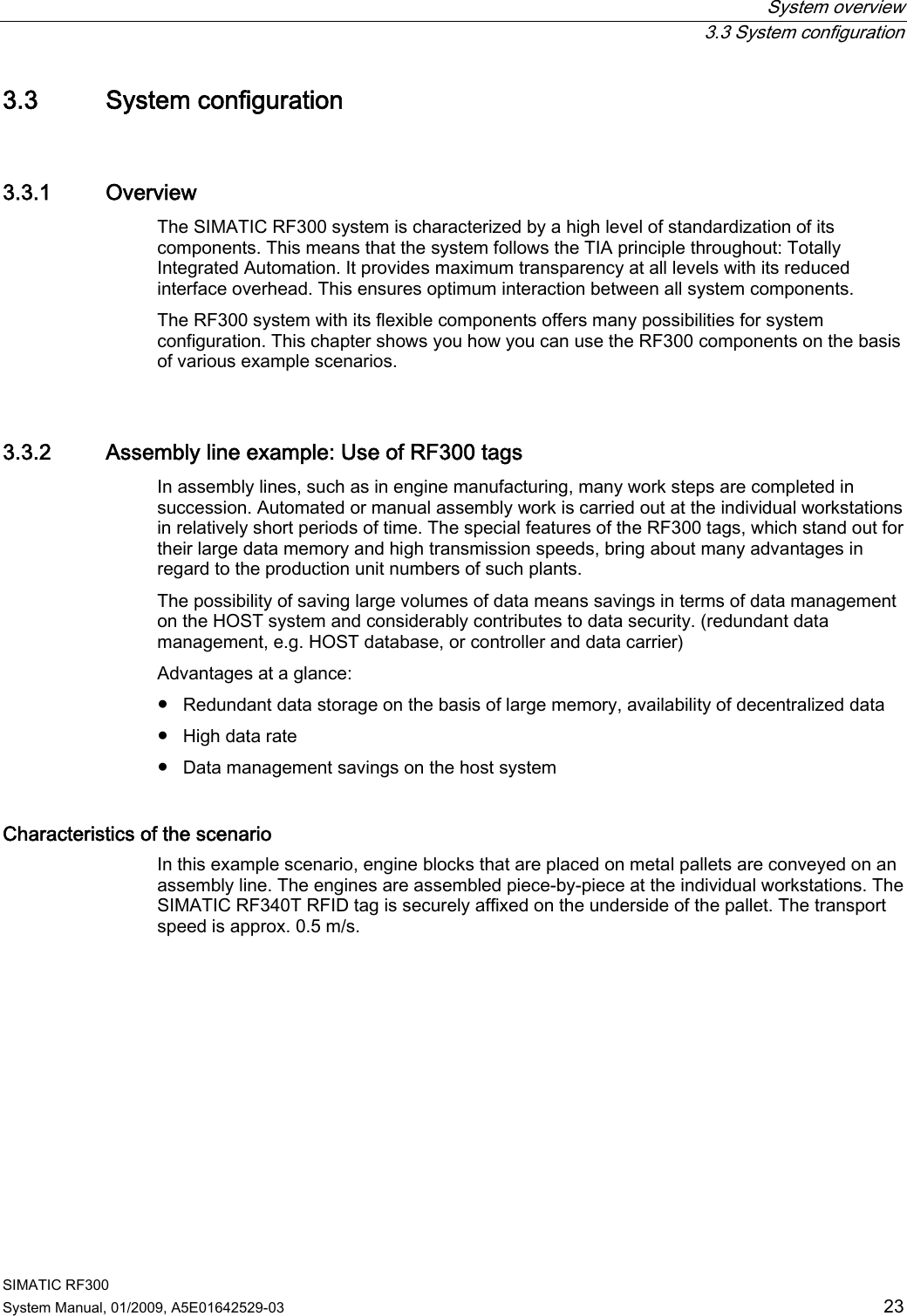
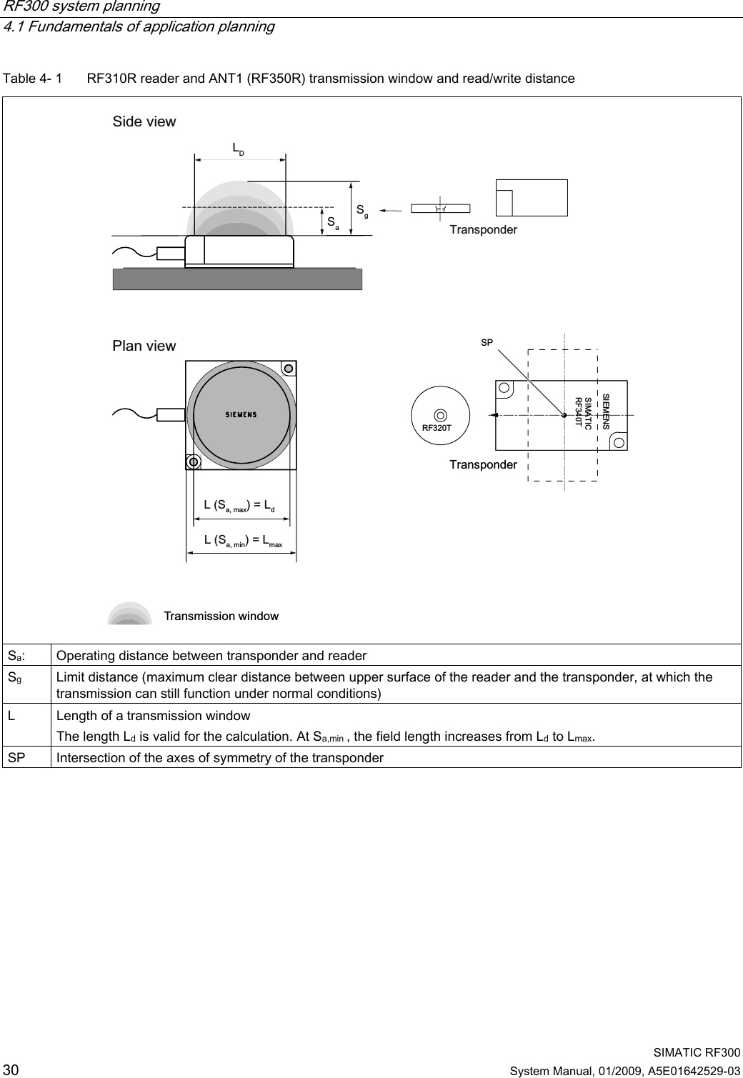
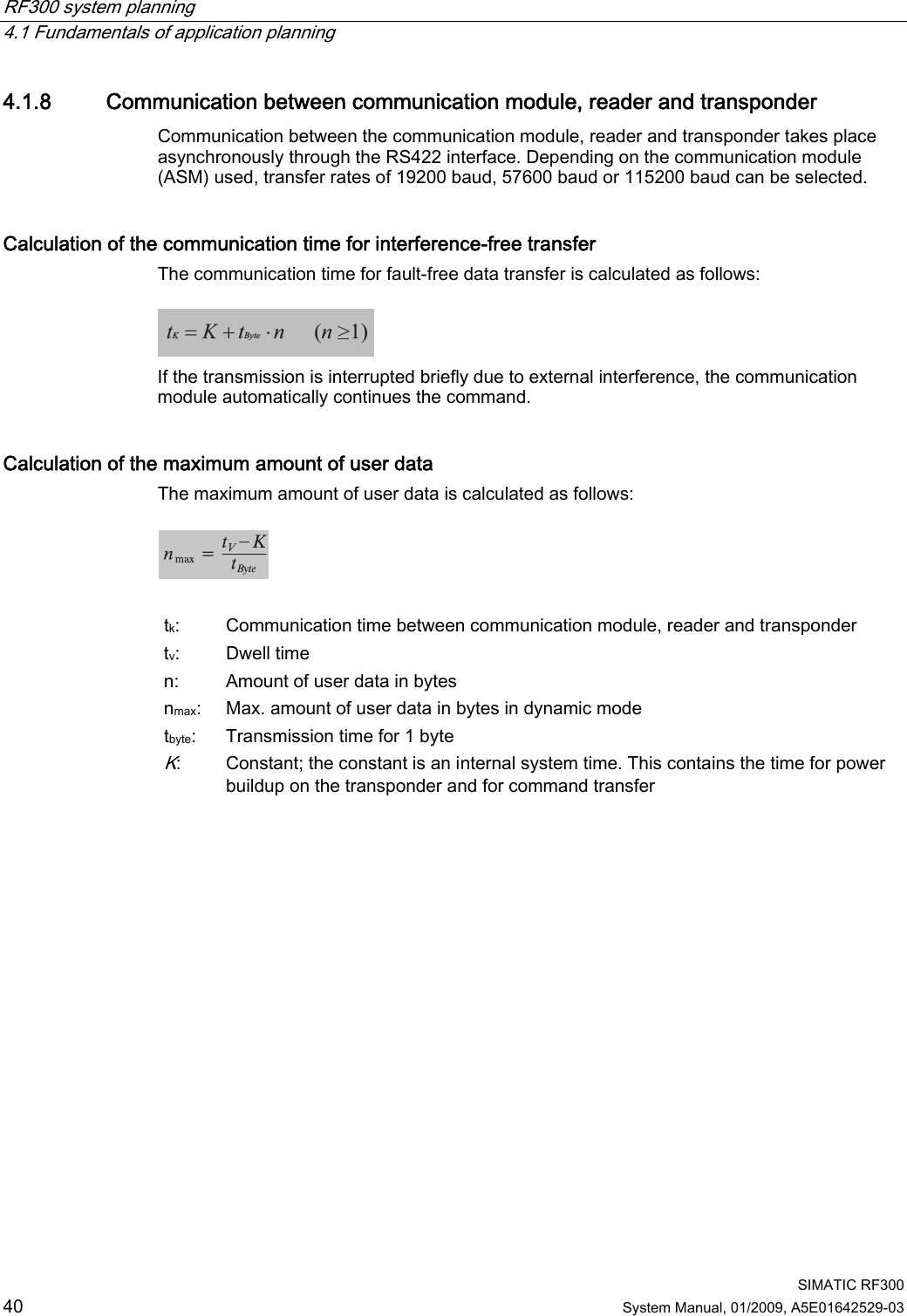
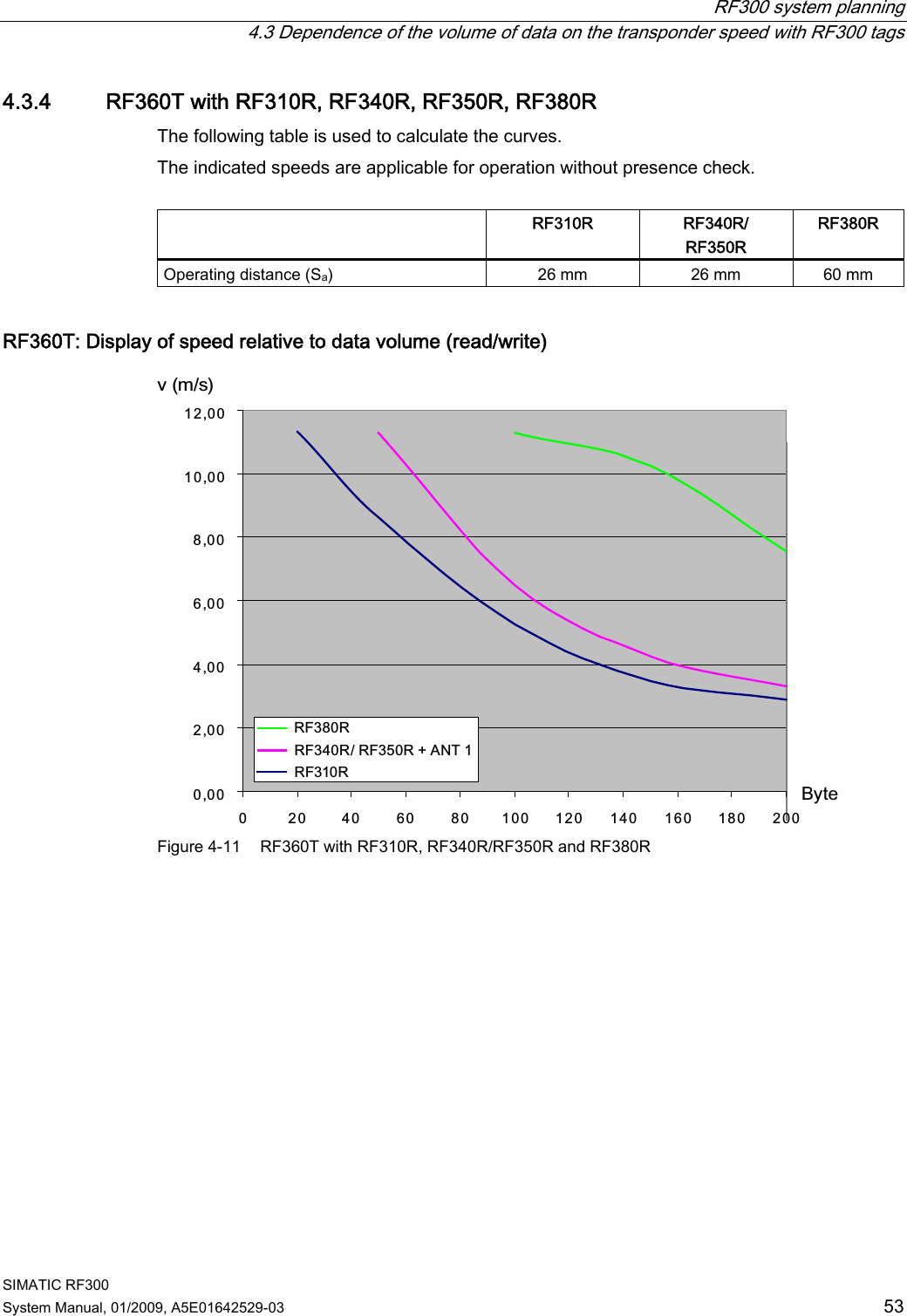
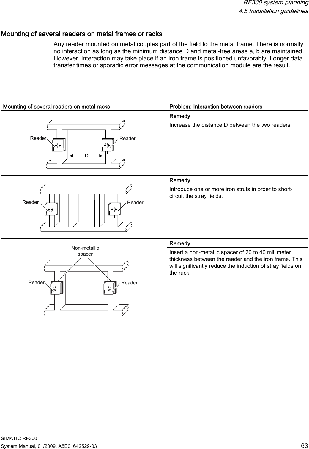
![RF300 system planning 4.1 Fundamentals of application planning SIMATIC RF300 System Manual, 01/2009, A5E01642529-03 39 4.1.7 Dwell time of the transponder The dwell time is the time in which the transponder remains within the transmission window of a reader. The reader can exchange data with the transponder during this time. The dwell time is calculated thus: 0,8 [ ][/]TagvL mtv m s⋅= tV: Dwell time of the transponder L: Length of the transmission window vTag: Speed of the transponder (tag) in dynamic mode 0,8: Constant factor used to compensate for temperature impacts and production tolerances The dwell time can be of any duration in static mode. The dwell time must be sufficiently long to allow communication with the transponder. The dwell time is defined by the system environment in dynamic mode. The volume of data to be transferred must be matched to the dwell time or vice versa. In general: Kvtt≥ tV:: Dwell time of the data memory within the field of the reader tK: Communication time between transponder and communication module](https://usermanual.wiki/Siemens/RF380R01/User-Guide-1144704-Page-39.png)
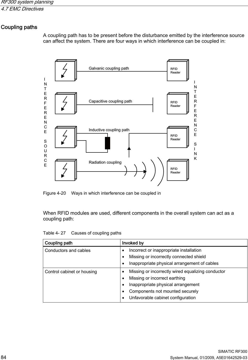
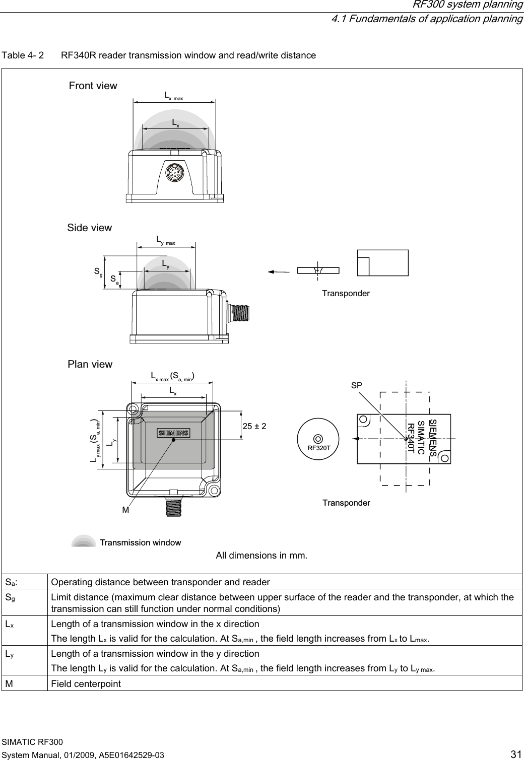
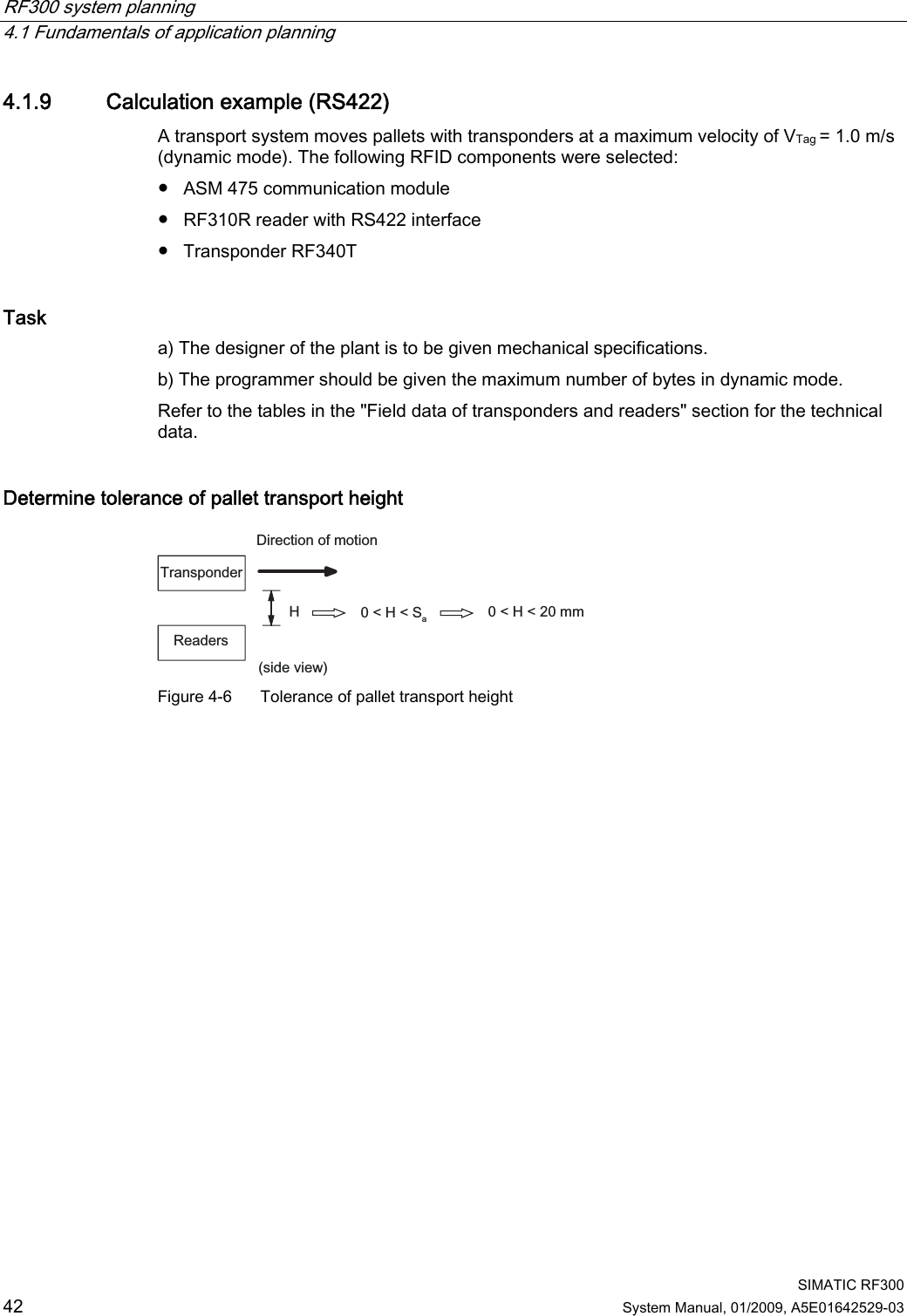
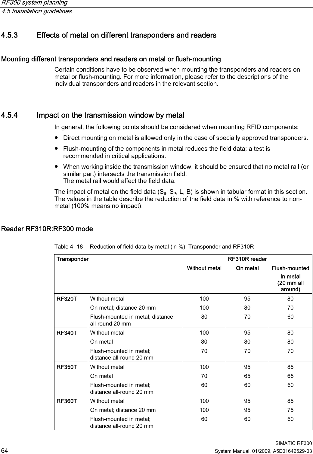
![RF300 system planning 4.1 Fundamentals of application planning SIMATIC RF300 System Manual, 01/2009, A5E01642529-03 41 Time constants K and tbyte for medium and high-performance applications Table 4- 5 Static mode RF300 mode FRAM ISO mode Read/write Read Write Data volume ≤ 233 bytes Data volume >233 bytes Data volume ≤ 233 bytes Data volume >233 bytes Independent of data volume Transfer rate [baud] K [ms] tbyte [ms] K [ms] tbyte [ms] K [ms] tbyte [ms] K [ms] tbyte [ms] K [ms] tbyte [ms] 19200 28 0.67 28 0.67 35 1.08 64 0.75 41 2.66 57600 15 0.30 25 0.22 34 0.59 34 0.59 28 2.28 115200 11 0.21 30 0.12 26 0.56 26 0.56 26 2.17 The values for K and tbyte include the overall time that is required for communication in static mode. It is built up from several different times: • Serial communication between communication module, reader and • Processing time between reader and transponder and their internal processing time. The values shown in the table must be used when calculating the maximum quantity of user data in static mode. They are applicable for both reading and writing in the FRAM area. For writing in the EEPROM area (max. 20 bytes), the byte time tByte is approx. 11 ms. Table 4- 6 Dynamic mode RF300 tags ISO tags Transfer rate [baud] Memory area K [ms] tbyte [ms] K [ms] tbyte [ms] Independent FRAM 8 0.13 - - Independent Write Read EEPROM 8 8 12.20 0.13 15 12 1.99 0.56 In dynamic mode, the values for K and tbyte are independent of the transmission speed. The communication time only includes the processing time between the reader and the transponder and the internal system processing time of these components. The communication times between the communication module and the reader do not have to be taken into account because the command for reading or writing is already active when the transponder enters the transmission field of the reader. The values shown above must be used when calculating the maximum quantity of user data in dynamic mode. They are applicable for both writing and reading. Time constants K and tbyte for low-performance applications (IQ-Sense) Table 4- 7 Static mode K (ms) tbyte (ms) Command 15 15 Read (FRAM/EEPROM area) 15 15 Write (FRAM area) 30 30 Write (EEPROM area) The table of time constants applies to every command. If a user command consists of several subcommands, the above tK formula must be applied to each subcommand.](https://usermanual.wiki/Siemens/RF380R01/User-Guide-1144704-Page-41.png)
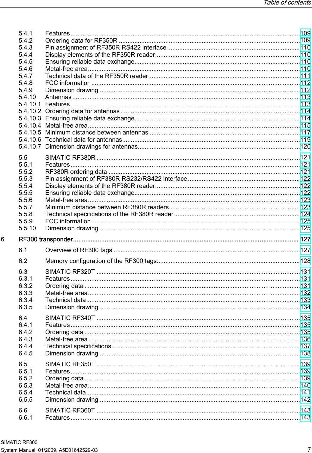
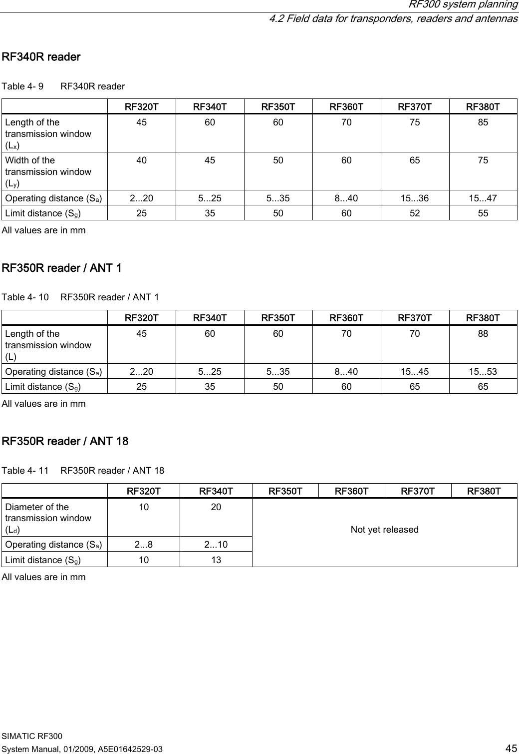
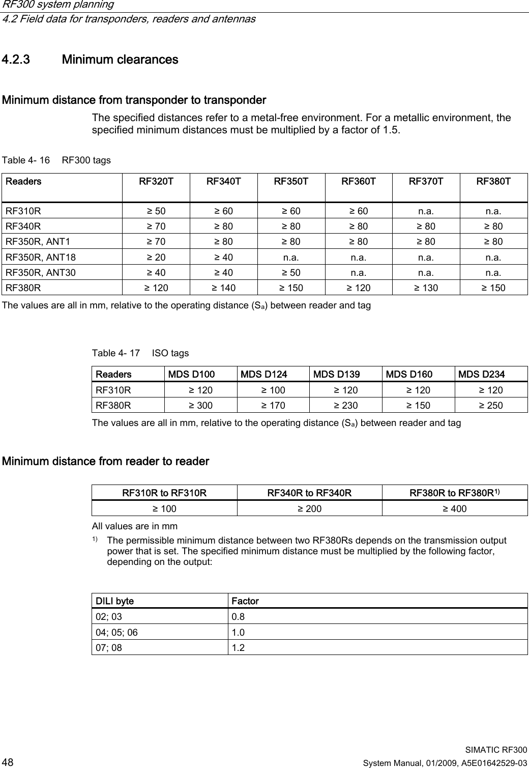
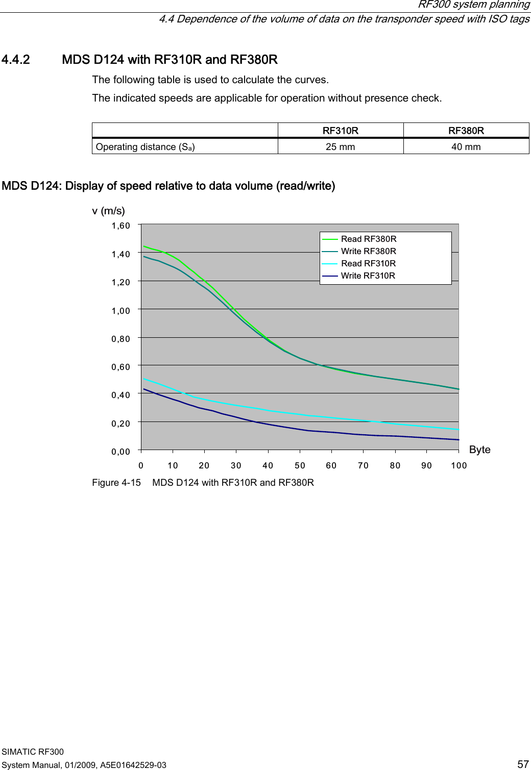
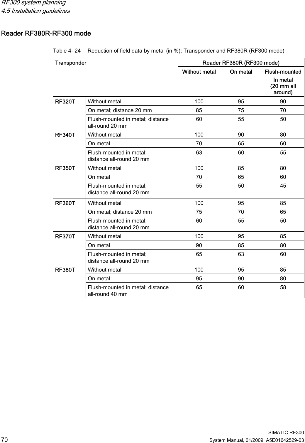
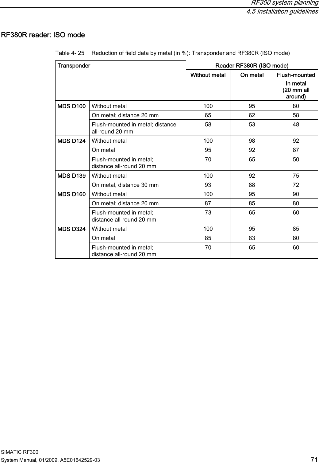
![RF300 system planning 4.2 Field data for transponders, readers and antennas SIMATIC RF300 44 System Manual, 01/2009, A5E01642529-03 4.2 Field data for transponders, readers and antennas The following table shows the field data for all SIMATIC RF300 components of transponders and readers. It facilitates the correct selection of a transponder and reader. All the technical specifications listed are typical data and are applicable for an ambient temperature of between 0 C and +50 °C, a supply voltage of between 22 V and 27 V DC and a metal-free environment. Tolerances of ±20 % are admissible due to production or temperature conditions. If the entire voltage range at the reader of 20 V DC to 30 V DC and/or the entire temperature range of transponders and readers is used, the field data are subject to further tolerances. Note Transmission gaps If the minimum operating distance (Sa) is not observed, a transmission gap can occur in the center of the field. Communication with the transponder is not possible in the transmission gap. 4.2.1 Field data of RF300 transponders Observe the following information for field data of RF300 transponders: ● A maximum median deviation of ±2 mm is possible in static mode (without affecting the field data) ● The field data are reduced by approx. 15% if the transponder enters the transmission window laterally (see also "Transmission window" figure) RF310R reader Table 4- 8 RF310R reader RF320T RF340T RF350T RF360T RF370T RF380T Length of the transmission window (L) 30 38 45 45 Operating distance (Sa) 2...10 2...20 5...22 [26] 5...26 Limit distance (Sg) 16 26 30 [35] 35 Combination with the RF310R is basically possible, but is not recommended because the antenna geometries for the reader and transponder are not ideally matched. All values are in mm Values in brackets [ ] refer to RF310R with the MLFB 6GT2801-1AB10](https://usermanual.wiki/Siemens/RF380R01/User-Guide-1144704-Page-44.png)
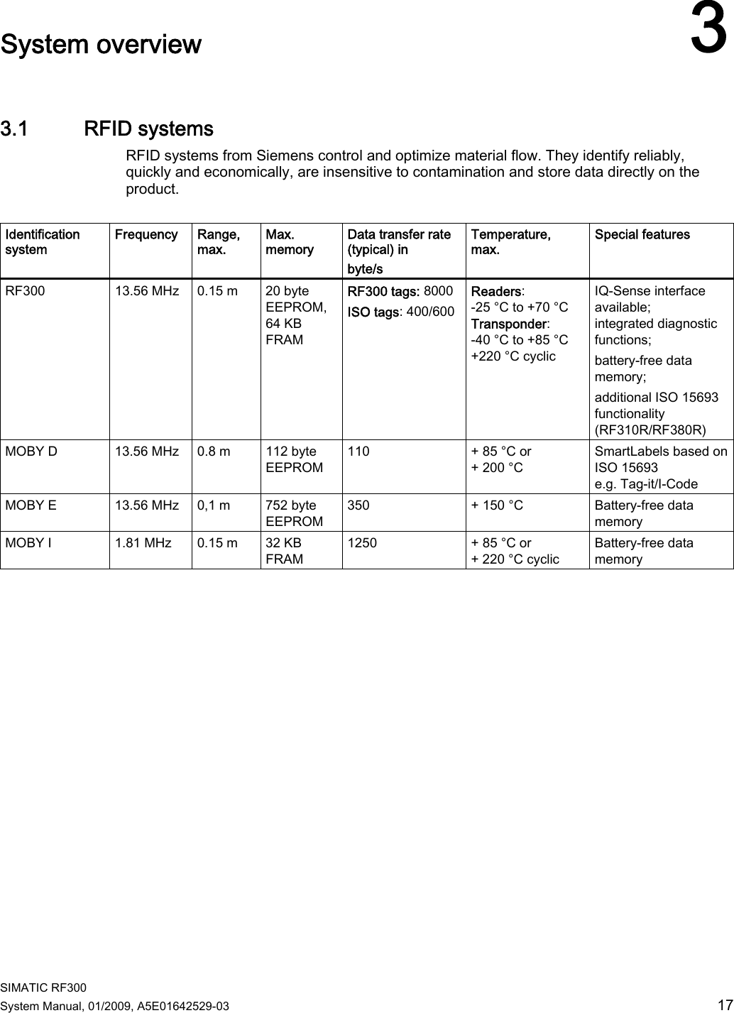
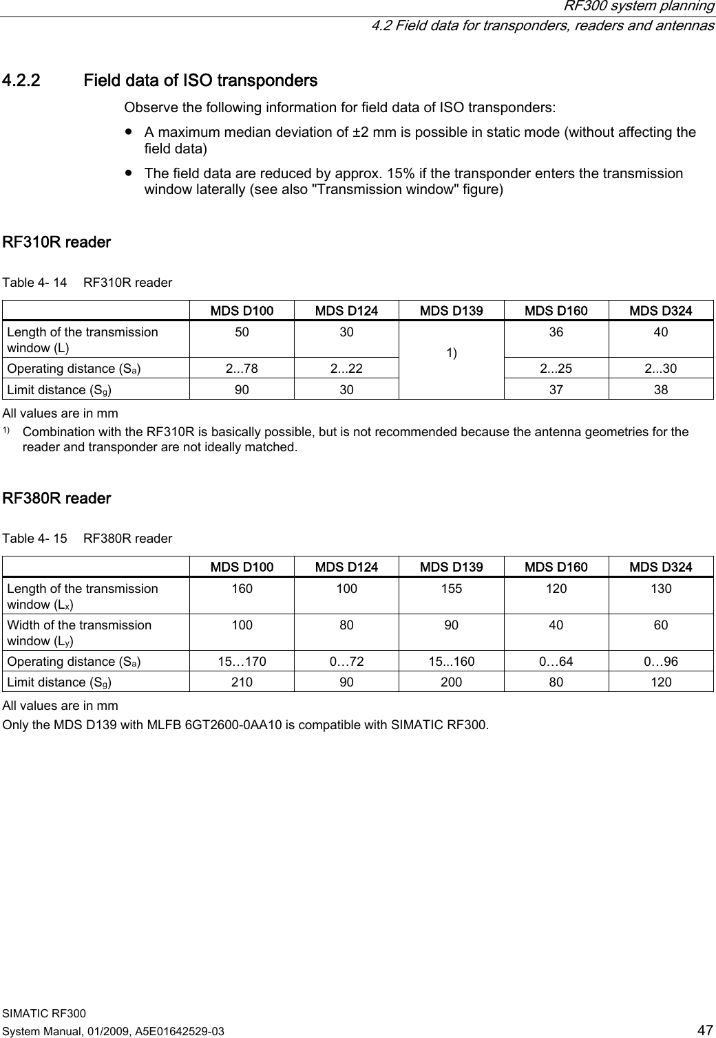
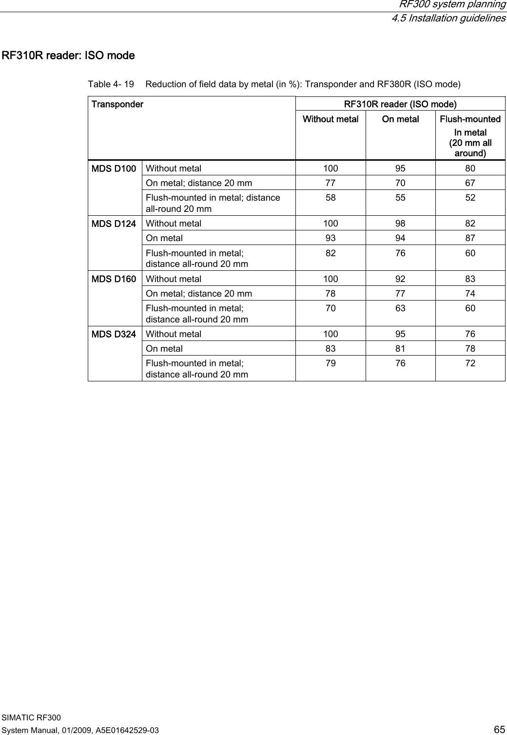
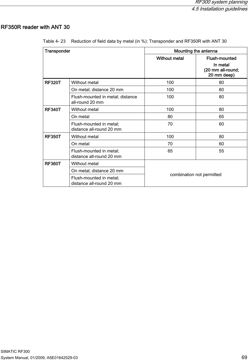
![RF300 system planning 4.2 Field data for transponders, readers and antennas SIMATIC RF300 46 System Manual, 01/2009, A5E01642529-03 RF350R reader / ANT 30 Table 4- 12 RF350R reader / ANT 30 RF320T RF340T RF350T RF360T RF370T RF380T Diameter of the transmission window (Ld) 15 25 25 Operating distance (Sa) 2...11 5...15 5...16 Limit distance (Sg) 15 20 22 Not yet released All values are in mm RF380R reader Table 4- 13 RF380R reader RF320T RF340T RF350T RF360T RF370T RF380T Length of the transmission window (Lx) 100 115 120 120 135 155 Width of the transmission window (Ly) 40 50 60 70 65 75 Operating distance (Sa) 2...30 [40] 20...70 [80] 35...70 [100] 40...120 35...85 [100] 25...85 [110] Limit distance (Sg) 47 [55] 90 [100] 105 [130] 140 [150] 125 [135] 125 [140] All values are in mm Values in brackets [ ] refer to RF380R with the MLFB 6GT2801-3AB10 The RF380R with MLFB 6GT2801-3AB10 gives the user the capability of setting the transmission output power with the aid of the "dili" (distance limiting) input parameter. For this, values from approx. 0.5 W to approx. 2.0 W can be set in 0.25 W increments. Depending on the setting, the change to the transmission output power increases the performance in the lower operating distance (low performance) or in the upper limit distance (high performance). The "dili" value range goes from 02 (= 0.5 W) and 05 (default value: 1.25 W) to 08 (= 2 W). Note A dili value setting outside of the value range of 02 to 08 leads to the default setting (05) and does not generate an error message. Also see Chapter Minimum clearances (Page 48) Section "Minimum distance from reader to reader". You can find exact information regarding the parameters in the Product Information "FB 45 and FC 45 input parameters for RF300 and ISO transponders" (http://support.automation.siemens.com/WW/view/en/33315697).](https://usermanual.wiki/Siemens/RF380R01/User-Guide-1144704-Page-46.png)
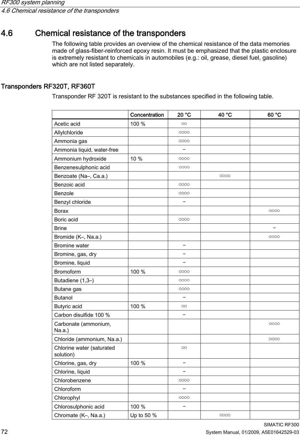
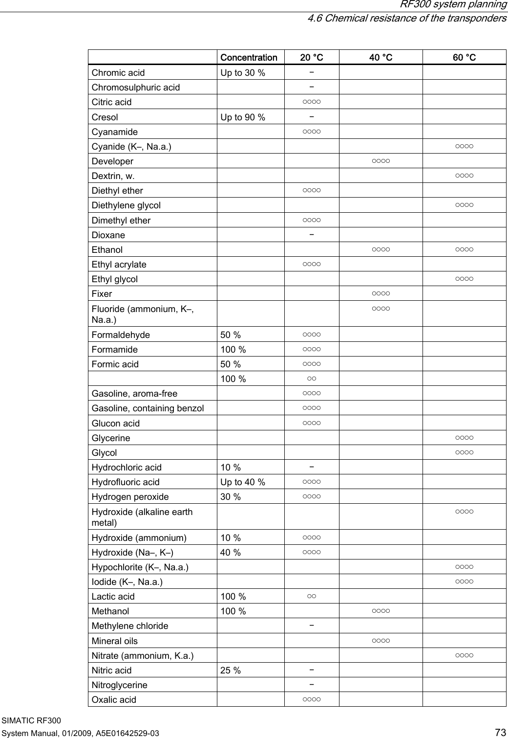
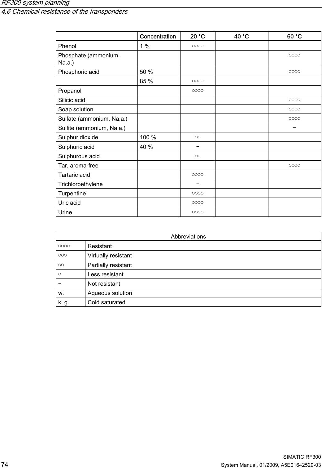
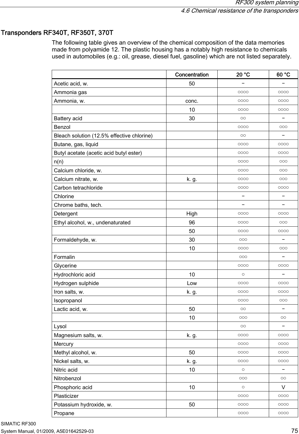
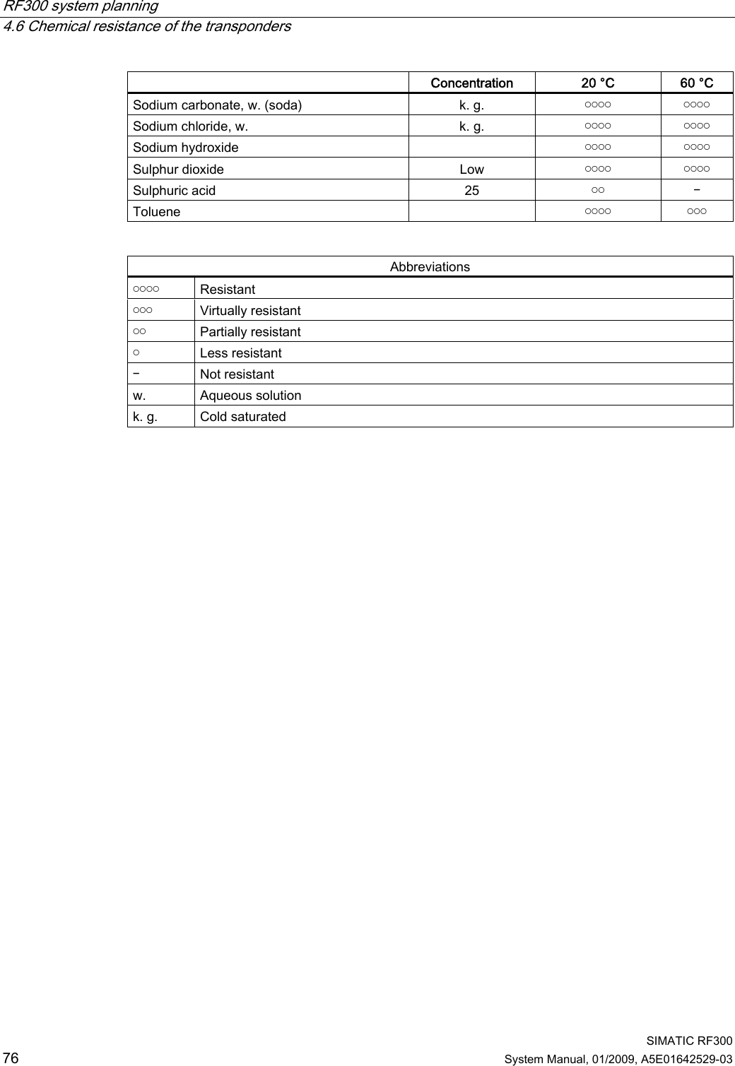
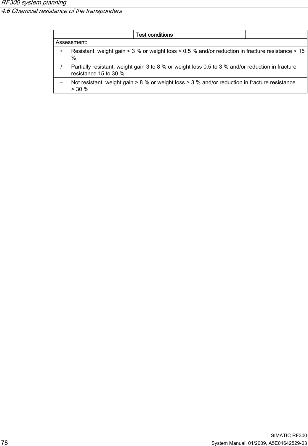
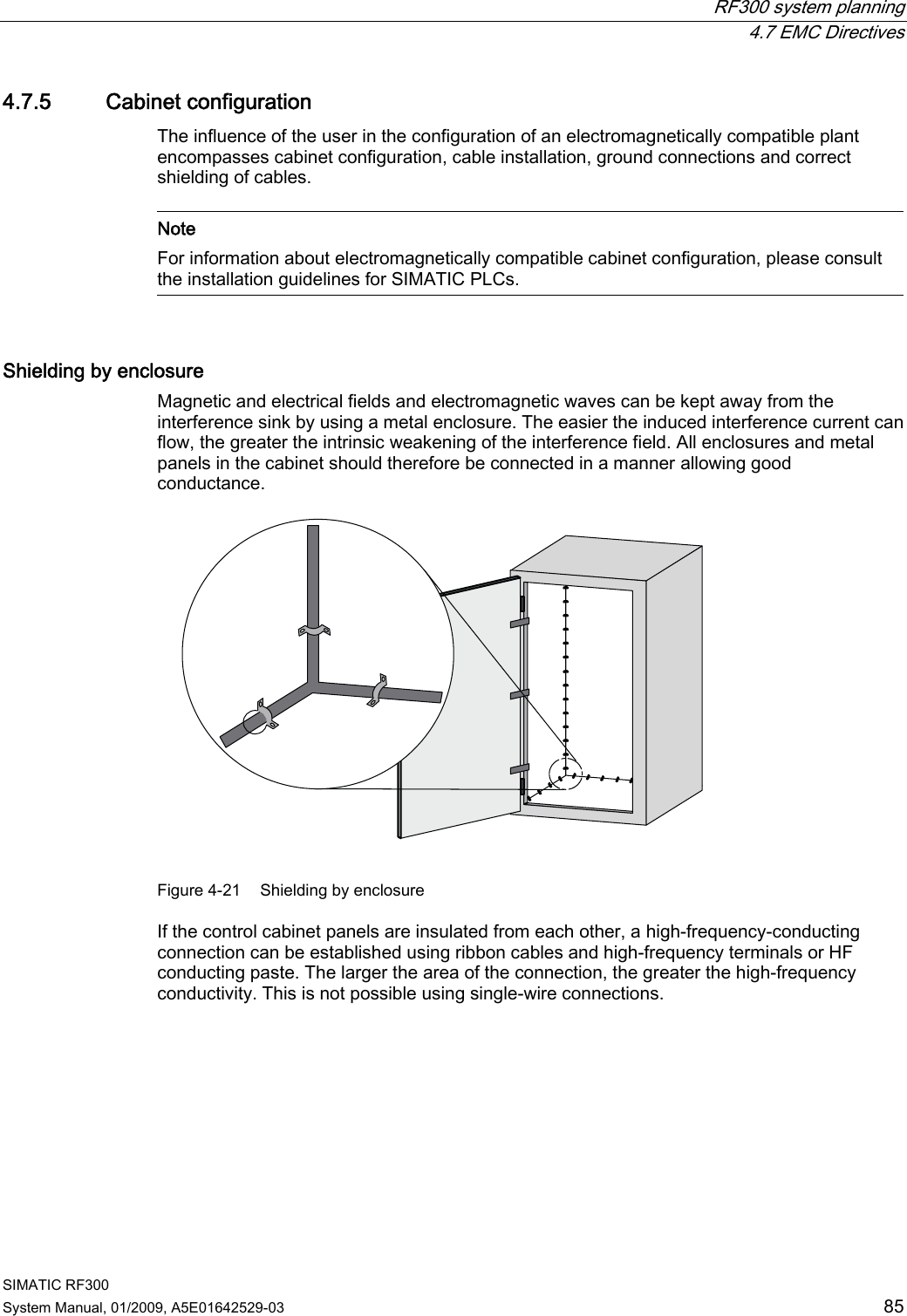
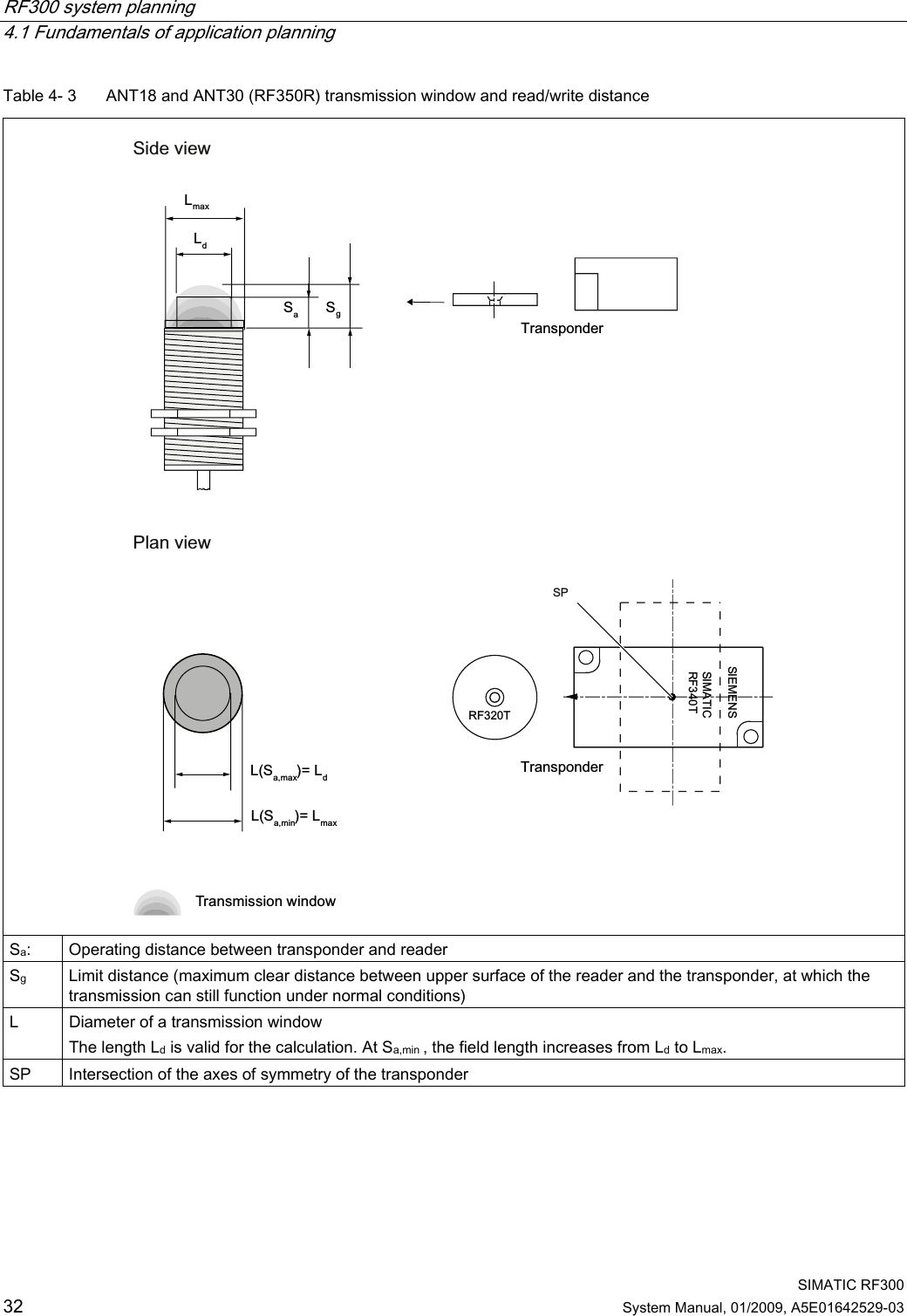
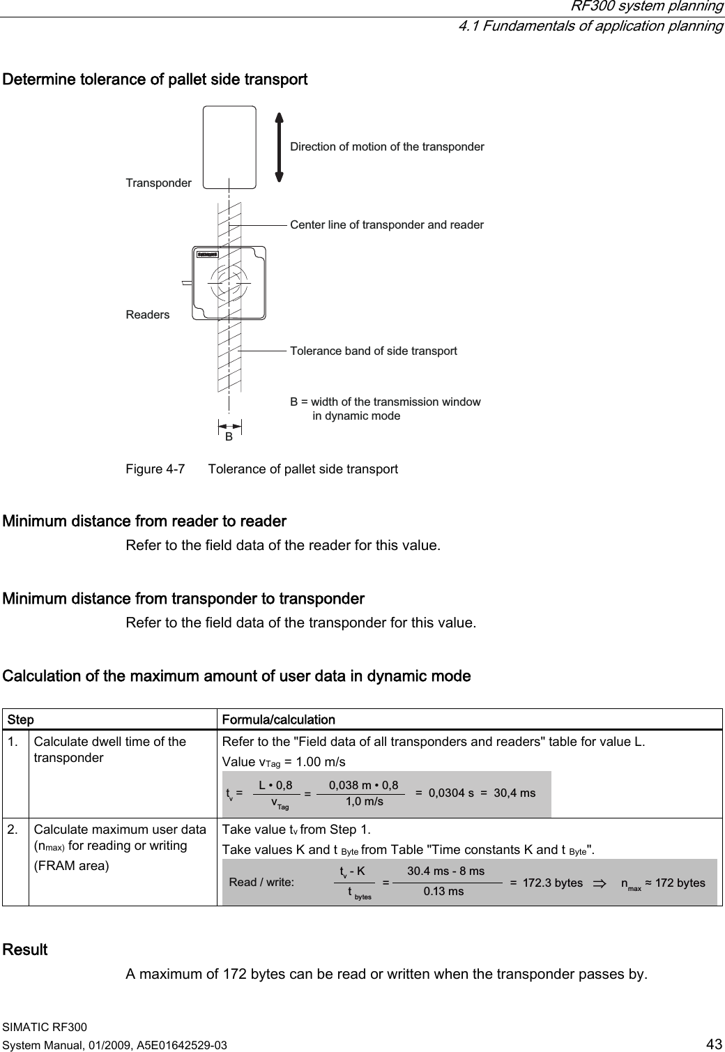
![RF300 system planning 4.6 Chemical resistance of the transponders SIMATIC RF300 System Manual, 01/2009, A5E01642529-03 77 Transponder RF380T The housing of the heat-resistant data storage unit is made of polyphenylene sulfide (PPS). The chemical resistance of the data storage unit is excellent. No solvent is known that can dissolve the plastic at temperatures below 200 °C. A reduction in the mechanical properties has been observed in aqueous solutions of hydrochloric acid (HCl) and nitric acid (HNO3) at 80 °C. The excellent resistance to all fuel types including methanol is a particular characteristic. The following table provides an overview of the chemicals investigated. Test conditions Substance Time[days] Temperature[°C] Evaluation Acetone 180 55 + Anti-freeze 180 120 + Brake fluid 40 80 + Butanon-2 (methyl ethyl ketone) 180 60 + Calcium chloride (saturated) 40 80 + Caustic soda (30%) 40 93 + Diesel fuel 180 80 + Diethyl ether 40 23 + Engine oil 40 80 + Frigen 113 40 23 + Hydrochloric acid (10%) 40 80 – Kerosine 40 60 + Methanol 180 60 + n-Butanol (butyl alcohol) 180 80 + n-butyl acetate 180 80 + Nitric acid (10%) 40 23 + Sodium chloride (saturated) 40 80 + Sodium hydroxide (30%) 180 80 + Sodium hypochlorite (5%) 30 80 / 180 80 – Sulphuric acid (10%) 40 23 + (10%) 40 (30%) 40 Tested fuels: 40 80 + (FAM-DIN 51 604-A) 180 80 / Toluene 1, 1, 1-trichloroethane 180 80 + Xylene Zinc chloride (saturated) 180 80 / 180 75 + 180 80 + 40 80 +](https://usermanual.wiki/Siemens/RF380R01/User-Guide-1144704-Page-77.png)