Siemens RF380R01 Tag Reader User Manual SIMATIC Sensors RFID systems SIMATIC RF300
Siemens AG Tag Reader SIMATIC Sensors RFID systems SIMATIC RF300
Siemens >
User Manual

SIMATIC Sensors RFID systems SIMATIC RF300
SIMATIC Sensors
System Manual · 01/2009
SIMATIC RF300
RFID SYSTEMS


Legal information
Warning notice system
This manual contains notices you have to observe in order to ensure your personal safety, as well as to prevent
damage to property. The notices referring to your personal safety are highlighted in the manual by a safety alert
symbol, notices referring only to property damage have no safety alert symbol. These notices shown below are
graded according to the degree of danger.
DANGER
indicates that death or severe personal injury will result if proper precautions are not taken.
WARNING
indicates that death or severe personal injury may result if proper precautions are not taken.
CAUTION
with a safety alert symbol, indicates that minor personal injury can result if proper precautions are not taken.
CAUTION
without a safety alert symbol, indicates that property damage can result if proper precautions are not taken.
NOTICE
indicates that an unintended result or situation can occur if the corresponding information is not taken into
account.
If more than one degree of danger is present, the warning notice representing the highest degree of danger will
be used. A notice warning of injury to persons with a safety alert symbol may also include a warning relating to
property damage.
Qualified Personnel
The device/system may only be set up and used in conjunction with this documentation. Commissioning and
operation of a device/system may only be performed by qualified personnel. Within the context of the safety notes
in this documentation qualified persons are defined as persons who are authorized to commission, ground and
label devices, systems and circuits in accordance with established safety practices and standards.
Proper use of Siemens products
Note the following:
WARNING
Siemens products may only be used for the applications described in the catalog and in the relevant technical
documentation. If products and components from other manufacturers are used, these must be recommended
or approved by Siemens. Proper transport, storage, installation, assembly, commissioning, operation and
maintenance are required to ensure that the products operate safely and without any problems. The permissible
ambient conditions must be adhered to. The information in the relevant documentation must be observed.
Trademarks
All names identified by ® are registered trademarks of the Siemens AG. The remaining trademarks in this
publication may be trademarks whose use by third parties for their own purposes could violate the rights of the
owner.
Disclaimer of Liability
We have reviewed the contents of this publication to ensure consistency with the hardware and software
described. Since variance cannot be precluded entirely, we cannot guarantee full consistency. However, the
information in this publication is reviewed regularly and any necessary corrections are included in subsequent
editions.
Siemens AG
Industry Sector
Postfach 48 48
90026 NÜRNBERG
GERMANY
A5E01642529-03
Ⓟ 01/2009
Copyright © Siemens AG 2005, 2009.
Technical data subject to change
SIMATIC RF300
System Manual, 01/2009, A5E01642529-03 5
Table of contents
1 Introduction.............................................................................................................................................. 11
1.1 Navigating in the system manual.................................................................................................11
1.2 Preface.........................................................................................................................................12
2 Safety information.................................................................................................................................... 15
3 System overview...................................................................................................................................... 17
3.1 RFID systems...............................................................................................................................17
3.2 SIMATIC RF300...........................................................................................................................18
3.2.1 RF300 system overview...............................................................................................................18
3.2.2 RFID components and their function ...........................................................................................19
3.2.3 Application areas of RF300..........................................................................................................22
3.3 System configuration ...................................................................................................................23
3.3.1 Overview ......................................................................................................................................23
3.3.2 Assembly line example: Use of RF300 tags................................................................................23
3.3.3 Example of container and paper board container handling: Use of ISO tags .............................25
3.4 System data .................................................................................................................................27
4 RF300 system planning ........................................................................................................................... 29
4.1 Fundamentals of application planning .........................................................................................29
4.1.1 Selection criteria for SIMATIC RF300 components.....................................................................29
4.1.2 Transmission window and read/write distance ............................................................................29
4.1.3 Width of the transmission window................................................................................................34
4.1.4 Impact of secondary fields ...........................................................................................................35
4.1.5 Permissible directions of motion of the transponder....................................................................37
4.1.6 Operation in static and dynamic mode ........................................................................................37
4.1.7 Dwell time of the transponder ......................................................................................................39
4.1.8 Communication between communication module, reader and transponder ...............................40
4.1.9 Calculation example (RS422) ......................................................................................................42
4.2 Field data for transponders, readers and antennas.....................................................................44
4.2.1 Field data of RF300 transponders ...............................................................................................44
4.2.2 Field data of ISO transponders....................................................................................................47
4.2.3 Minimum clearances ....................................................................................................................48
4.3 Dependence of the volume of data on the transponder speed with RF300 tags ........................50
4.3.1 RF320T with RF310R, RF340R, RF350R, RF380R....................................................................50
4.3.2 RF340T with RF310R, RF340R, RF350R, RF380R....................................................................51
4.3.3 RF350T with RF310R, RF340R, RF350R, RF380R....................................................................52
4.3.4 RF360T with RF310R, RF340R, RF350R, RF380R....................................................................53
4.3.5 RF370T with RF340R, RF350R, RF380R ...................................................................................54
4.3.6 RF380T with RF340R, RF350R, RF380R ...................................................................................55
4.4 Dependence of the volume of data on the transponder speed with ISO tags .............................56
4.4.1 MDS D100 with RF310R and RF380R ........................................................................................56
4.4.2 MDS D124 with RF310R and RF380R ........................................................................................57
4.4.3 MDS D139 with RF310R and RF380R ........................................................................................58
4.4.4 MDS D160 with RF310R and RF380R ........................................................................................59

Table of contents
SIMATIC RF300
6 System Manual, 01/2009, A5E01642529-03
4.4.5 MDS D324 with RF310R and RF380R ....................................................................................... 60
4.5 Installation guidelines.................................................................................................................. 61
4.5.1 Overview ..................................................................................................................................... 61
4.5.2 Reduction of interference due to metal ....................................................................................... 61
4.5.3 Effects of metal on different transponders and readers.............................................................. 64
4.5.4 Impact on the transmission window by metal ............................................................................. 64
4.6 Chemical resistance of the transponders....................................................................................72
4.7 EMC Directives ........................................................................................................................... 79
4.7.1 Overview ..................................................................................................................................... 79
4.7.2 What does EMC mean?.............................................................................................................. 80
4.7.3 Basic rules................................................................................................................................... 81
4.7.4 Propagation of electromagnetic interference ..............................................................................82
4.7.5 Cabinet configuration .................................................................................................................. 85
4.7.6 Prevention of interference sources ............................................................................................. 88
4.7.7 Equipotential bonding.................................................................................................................. 89
4.7.8 Cable shielding............................................................................................................................ 90
5 Readers................................................................................................................................................... 93
5.1 SIMATIC RF310R with IQ-Sense interface................................................................................. 94
5.1.1 Features ...................................................................................................................................... 94
5.1.2 Ordering data of RF310R with IQ-Sense interface ..................................................................... 94
5.1.3 Pin assignment of RF310R IQ-Sense interface.......................................................................... 95
5.1.4 Display elements of the RF310R reader with IQ-Sense interface .............................................. 95
5.1.5 Ensuring reliable data exchange................................................................................................. 95
5.1.6 Metal-free area............................................................................................................................ 96
5.1.7 Minimum distance between RF310R readers............................................................................. 96
5.1.8 Technical data for RF310R reader with IQ-Sense interface....................................................... 97
5.1.9 FCC information .......................................................................................................................... 98
5.1.10 Dimension drawing...................................................................................................................... 98
5.2 SIMATIC RF310R with RS422 interface..................................................................................... 99
5.2.1 Features ...................................................................................................................................... 99
5.2.2 Ordering data for RF310R with RS422 interface ........................................................................ 99
5.2.3 Pin assignment of RF310R RS422 interface .............................................................................. 99
5.2.4 Display elements of the RF310R reader with RS422 interface ................................................ 100
5.2.5 Ensuring reliable data exchange............................................................................................... 100
5.2.6 Metal-free area.......................................................................................................................... 100
5.2.7 Minimum distance between RF310R readers........................................................................... 101
5.2.8 Technical specifications of the RF310R reader with RS422 interface...................................... 102
5.2.9 FCC information ........................................................................................................................ 103
5.2.10 Dimension drawing.................................................................................................................... 103
5.3 SIMATIC RF340R ..................................................................................................................... 104
5.3.1 Features .................................................................................................................................... 104
5.3.2 Ordering data for RF340R......................................................................................................... 104
5.3.3 Pin assignment of RF340R RS422 interface ............................................................................ 105
5.3.4 Display elements of the RF340R reader................................................................................... 105
5.3.5 Ensuring reliable data exchange............................................................................................... 105
5.3.6 Metal-free area.......................................................................................................................... 106
5.3.7 Minimum distance between RF340R readers........................................................................... 106
5.3.8 Technical data of the RF340R reader....................................................................................... 107
5.3.9 FCC information ........................................................................................................................ 108
5.3.10 Dimension drawing.................................................................................................................... 108
5.4 SIMATIC RF350R ..................................................................................................................... 109

Table of contents
SIMATIC RF300
System Manual, 01/2009, A5E01642529-03 7
5.4.1 Features.....................................................................................................................................109
5.4.2 Ordering data for RF350R .........................................................................................................109
5.4.3 Pin assignment of RF350R RS422 interface.............................................................................110
5.4.4 Display elements of the RF350R reader....................................................................................110
5.4.5 Ensuring reliable data exchange................................................................................................110
5.4.6 Metal-free area...........................................................................................................................110
5.4.7 Technical data of the RF350R reader........................................................................................111
5.4.8 FCC information.........................................................................................................................112
5.4.9 Dimension drawing ....................................................................................................................112
5.4.10 Antennas....................................................................................................................................113
5.4.10.1 Features.....................................................................................................................................113
5.4.10.2 Ordering data for antennas........................................................................................................114
5.4.10.3 Ensuring reliable data exchange................................................................................................114
5.4.10.4 Metal-free area...........................................................................................................................115
5.4.10.5 Minimum distance between antennas .......................................................................................117
5.4.10.6 Technical data for antennas.......................................................................................................119
5.4.10.7 Dimension drawings for antennas..............................................................................................120
5.5 SIMATIC RF380R ......................................................................................................................121
5.5.1 Features.....................................................................................................................................121
5.5.2 RF380R ordering data ...............................................................................................................121
5.5.3 Pin assignment of RF380R RS232/RS422 interface.................................................................122
5.5.4 Display elements of the RF380R reader....................................................................................122
5.5.5 Ensuring reliable data exchange................................................................................................122
5.5.6 Metal-free area...........................................................................................................................123
5.5.7 Minimum distance between RF380R readers............................................................................123
5.5.8 Technical specifications of the RF380R reader.........................................................................124
5.5.9 FCC information.........................................................................................................................125
5.5.10 Dimension drawing ....................................................................................................................125
6 RF300 transponder................................................................................................................................ 127
6.1 Overview of RF300 tags ............................................................................................................127
6.2 Memory configuration of the RF300 tags...................................................................................128
6.3 SIMATIC RF320T ......................................................................................................................131
6.3.1 Features.....................................................................................................................................131
6.3.2 Ordering data .............................................................................................................................131
6.3.3 Metal-free area...........................................................................................................................132
6.3.4 Technical data............................................................................................................................133
6.3.5 Dimension drawing ....................................................................................................................134
6.4 SIMATIC RF340T ......................................................................................................................135
6.4.1 Features.....................................................................................................................................135
6.4.2 Ordering data .............................................................................................................................135
6.4.3 Metal-free area...........................................................................................................................136
6.4.4 Technical specifications .............................................................................................................137
6.4.5 Dimension drawing ....................................................................................................................138
6.5 SIMATIC RF350T ......................................................................................................................139
6.5.1 Features.....................................................................................................................................139
6.5.2 Ordering data .............................................................................................................................139
6.5.3 Metal-free area...........................................................................................................................140
6.5.4 Technical data............................................................................................................................141
6.5.5 Dimension drawing ....................................................................................................................142
6.6 SIMATIC RF360T ......................................................................................................................143
6.6.1 Features.....................................................................................................................................143

Table of contents
SIMATIC RF300
8 System Manual, 01/2009, A5E01642529-03
6.6.2 Ordering data ............................................................................................................................ 143
6.6.3 Metal-free area.......................................................................................................................... 144
6.6.4 Technical data........................................................................................................................... 146
6.6.5 Dimension drawing.................................................................................................................... 147
6.7 SIMATIC RF370T...................................................................................................................... 148
6.7.1 Features .................................................................................................................................... 148
6.7.2 Ordering data ............................................................................................................................ 148
6.7.3 Metal-free area.......................................................................................................................... 149
6.7.4 Mounting instructions ................................................................................................................ 150
6.7.5 Technical data for RF370T with 32 KB FRAM.......................................................................... 151
6.7.6 Dimensional drawing................................................................................................................. 152
6.8 SIMATIC RF380T...................................................................................................................... 153
6.8.1 Features .................................................................................................................................... 153
6.8.2 Ordering data ............................................................................................................................ 154
6.8.3 Installation guidelines for RF380T ............................................................................................ 155
6.8.3.1 Mounting instructions ................................................................................................................ 155
6.8.3.2 Metal-free area.......................................................................................................................... 158
6.8.4 Configuring instructions............................................................................................................. 159
6.8.4.1 Temperature dependence of the transmission window ............................................................ 159
6.8.4.2 Temperature response in cyclic operation ................................................................................ 161
6.8.5 Technical specifications ............................................................................................................ 164
6.8.6 Dimensional drawing................................................................................................................. 165
7 ISO transponder .................................................................................................................................... 167
7.1 Memory configuration of the ISO tags ...................................................................................... 168
7.2 MDS D100................................................................................................................................. 170
7.2.1 Characteristics .......................................................................................................................... 170
7.2.2 Ordering data ............................................................................................................................ 170
7.2.3 Metal-free area.......................................................................................................................... 171
7.2.4 Technical data........................................................................................................................... 174
7.2.5 Dimension drawing.................................................................................................................... 175
7.3 MDS D124................................................................................................................................. 176
7.3.1 Characteristics .......................................................................................................................... 176
7.3.2 Ordering data ............................................................................................................................ 176
7.3.3 Metal-free area.......................................................................................................................... 177
7.3.4 Technical specifications ............................................................................................................ 178
7.3.5 Dimension drawings.................................................................................................................. 179
7.4 MDS D139................................................................................................................................. 180
7.4.1 Characteristics .......................................................................................................................... 180
7.4.2 Ordering data ............................................................................................................................ 181
7.4.3 Metal-free area.......................................................................................................................... 182
7.4.4 Technical specifications ............................................................................................................ 183
7.4.5 ATEX......................................................................................................................................... 184
7.4.6 Dimension drawings.................................................................................................................. 185
7.5 MDS D160................................................................................................................................. 186
7.5.1 Characteristics .......................................................................................................................... 186
7.5.2 Ordering data ............................................................................................................................ 186
7.5.3 Metal-free area.......................................................................................................................... 187
7.5.4 Technical specifications ............................................................................................................ 188
7.5.5 Dimension drawings.................................................................................................................. 189
7.6 MDS D324................................................................................................................................. 190
7.6.1 Characteristics .......................................................................................................................... 190

Table of contents
SIMATIC RF300
System Manual, 01/2009, A5E01642529-03 9
7.6.2 Ordering data .............................................................................................................................190
7.6.3 Metal-free area...........................................................................................................................191
7.6.4 Technical specifications .............................................................................................................192
7.6.5 Dimension drawings...................................................................................................................193
8 System integration................................................................................................................................. 195
8.1 Introduction ................................................................................................................................195
8.2 ASM 452 ....................................................................................................................................197
8.2.1 Features.....................................................................................................................................197
8.2.2 Ordering data .............................................................................................................................198
8.2.3 Pin assignment and display elements .......................................................................................199
8.2.4 Configuration..............................................................................................................................200
8.2.5 Technical data............................................................................................................................204
8.2.6 PROFIBUS Diagnosis................................................................................................................205
8.2.7 Dimension drawing ....................................................................................................................206
8.3 ASM 456 ....................................................................................................................................207
8.4 ASM 473 ....................................................................................................................................208
8.4.1 Features.....................................................................................................................................208
8.4.2 Ordering data .............................................................................................................................209
8.4.3 Pin assignment and display elements .......................................................................................210
8.4.4 Configuration..............................................................................................................................211
8.4.5 Technical data............................................................................................................................215
8.4.6 Dimensional drawings................................................................................................................216
8.5 ASM 475 ....................................................................................................................................217
8.5.1 Features.....................................................................................................................................217
8.5.2 Ordering data .............................................................................................................................218
8.5.3 Indicators....................................................................................................................................219
8.5.4 Configuration..............................................................................................................................221
8.5.5 Technical data............................................................................................................................224
8.6 RF170C......................................................................................................................................225
8.7 RF180C......................................................................................................................................226
8.8 8xIQ-Sense ................................................................................................................................227
8.8.1 Features.....................................................................................................................................227
8.8.2 Ordering data .............................................................................................................................227
8.8.3 Indicators....................................................................................................................................228
8.8.4 Configuration..............................................................................................................................229
8.8.5 Addressing .................................................................................................................................231
8.8.6 Technical data............................................................................................................................233
9 System diagnostics................................................................................................................................ 235
9.1 Error codes.................................................................................................................................235
9.2 Diagnostics functions .................................................................................................................236
9.2.1 Overview ....................................................................................................................................236
9.2.2 Reader diagnostics with SLG STATUS .....................................................................................237
9.2.3 Transponder diagnostics with MDS STATUS............................................................................240
A Appendix................................................................................................................................................ 243
A.1 Certificates and approvals .........................................................................................................243
A.1.1 Certificates and Approvals.........................................................................................................243
A.2 Accessories................................................................................................................................246

Table of contents
SIMATIC RF300
10 System Manual, 01/2009, A5E01642529-03
A.3 Connecting cable ...................................................................................................................... 247
A.3.1 Reader RF3xxR (RS422) with ASM 452/ASM 473................................................................... 247
A.3.2 Reader RF3xxR (RS422) with ASM 456/RF170C/RF180C...................................................... 248
A.3.3 Reader RF3xxR (RS422) with ASM 475................................................................................... 249
A.3.4 RF310R and IQ-Sense.............................................................................................................. 250
A.3.5 Reader RF380R (RS232) - PC ................................................................................................. 251
A.4 Ordering data ............................................................................................................................ 252
A.5 Service & Support ..................................................................................................................... 259
Glossary ................................................................................................................................................ 261
Index...................................................................................................................................................... 267

SIMATIC RF300
System Manual, 01/2009, A5E01642529-03 11
Introduction 1
1.1 Navigating in the system manual
Structure of contents Contents
Table of contents Organization of the documentation, including the index of pages and chapters
Introduction Purpose, layout and description of the important topics.
Safety instructions Refers to all the valid technical safety aspects which have to be adhered to while installing,
commissioning and operating from the product/system view and with reference to statutory
regulations.
System overview Overview of all RF identification systems, system overview of SIMATIC RF300
RFID system planning Information about possible applications of SIMATIC RF300, support for application
planning, tools for finding suitable SIMATIC RF300 components.
Readers Description of readers which can be used for SIMATIC RF300
RF300 transponder Description of RF300 transponders which can be used for SIMATIC RF300
ISO transponder Description of ISO transponders which can be used for SIMATIC RF300
System integration Overview of the communication modules and function blocks that can be used for SIMATIC
RF300
System diagnostics Description of system diagnostics available for SIMATIC RF300
Appendix • Certificates and approvals
• Accessories
• Connecting cable
• Ordering data
• Service & Support

Introduction
1.2 Preface
SIMATIC RF300
12 System Manual, 01/2009, A5E01642529-03
1.2 Preface
Purpose of this document
This system manual contains all the information needed to plan and configure the system.
It is intended both for programming and testing/debugging personnel who commission the
system themselves and connect it with other units (automation systems, further
programming devices), as well as for service and maintenance personnel who install
expansions or carry out fault/error analyses.
Scope of validity of this document
This documentation is valid for all supplied variations of the SIMATIC RF300 system and
describes the state of delivery as of January 2009.
Conventions
The following terms/abbreviations are used synonymously in this document:
● Reader, read/write device, write/read device
● Tag, transponder, mobile data memory, data carrier, MDS
● Communication module, interface module, ASM
History
Currently released versions of the SIMATIC RF300 system manual:
Edition Remark
05/2005 First Edition
11/2005 Revised edition, components added: RF310R with RS422 interface, RF350T and
RF360T; ASM 452, ASM 456, ASM 473 and ASM 475
04/2006 Revised edition, components added: RF340R as well as RF350R with the antenna
types ANT 1, ANT 18 and ANT 30
12/2006 Revised edition, components added: RF370T, RF380T and RF170C
07/2007 Revised edition, degrees of protection changed for the RF300 reader
09/2007 Revised edition, components added: RF380R and RF180C
06/2008 Revised edition
01/2009 Revised edition, expanded by the reader functions "RF300 Tags" and "ISO Tags" for
the SIMATIC RF310R and SIMATIC RF380R readers
Declaration of conformity
The EC declaration of conformity and the corresponding documentation are made available
to authorities in accordance with the EC directives stated above. Your local sales
representative can provide these on request.

Introduction
1.2 Preface
SIMATIC RF300
System Manual, 01/2009, A5E01642529-03 13
Observance of installation guidelines
The installation guidelines and safety instructions given in this documentation must be
followed during commissioning and operation.

Introduction
1.2 Preface
SIMATIC RF300
14 System Manual, 01/2009, A5E01642529-03

SIMATIC RF300
System Manual, 01/2009, A5E01642529-03 15
Safety information 2
SIMATIC RFID products comply with the salient safety specifications to IEC, VDE, EN, UL
and CSA. If you have questions about the validity of the installation in the planned
environment, please contact your service representative.
CAUTION
Alterations to the devices are not permitted.
Failure to observe this requirement shall constitute a revocation of the radio equipment
approval, CE approval and manufacturer's warranty.
Repairs
Repairs may only be carried out by authorized qualified personnel.
WARNING
Unauthorized opening of and improper repairs to the device may result in substantial
damage to equipment or risk of personal injury to the user.
System expansion
Only install system expansion devices designed for this device. If you install other upgrades,
you may damage the system or violate the safety requirements and regulations for radio
frequency interference suppression. Contact your technical support team or your sales outlet
to find out which system upgrades are suitable for installation.
CAUTION
If you cause system defects by installing or exchanging system expansion devices, the
warranty becomes void.

Safety information
SIMATIC RF300
16 System Manual, 01/2009, A5E01642529-03

SIMATIC RF300
System Manual, 01/2009, A5E01642529-03 17
System overview 3
3.1 RFID systems
RFID systems from Siemens control and optimize material flow. They identify reliably,
quickly and economically, are insensitive to contamination and store data directly on the
product.
Identification
system
Frequency Range,
max.
Max.
memory
Data transfer rate
(typical) in
byte/s
Temperature,
max.
Special features
RF300 13.56 MHz 0.15 m 20 byte
EEPROM,
64 KB
FRAM
RF300 tags: 8000
ISO tags: 400/600
Readers:
-25 °C to +70 °C
Transponder:
-40 °C to +85 °C
+220 °C cyclic
IQ-Sense interface
available;
integrated diagnostic
functions;
battery-free data
memory;
additional ISO 15693
functionality
(RF310R/RF380R)
MOBY D 13.56 MHz 0.8 m 112 byte
EEPROM
110 + 85 °C or
+ 200 °C
SmartLabels based on
ISO 15693
e.g. Tag-it/I-Code
MOBY E 13.56 MHz 0,1 m 752 byte
EEPROM
350 + 150 °C Battery-free data
memory
MOBY I 1.81 MHz 0.15 m 32 KB
FRAM
1250 + 85 °C or
+ 220 °C cyclic
Battery-free data
memory

System overview
3.2 SIMATIC RF300
SIMATIC RF300
18 System Manual, 01/2009, A5E01642529-03
3.2 SIMATIC RF300
3.2.1 RF300 system overview
SIMATIC RF300 is an inductive identification system specially designed for use in industrial
production for the control and optimization of material flow.
Thanks to its compact dimensions, RF300 is the obvious choice where installation conditions
are restricted, especially for assembly lines, handling systems and workpiece carrier
systems. RF300 is suitable for both simple and demanding RFID applications and it stands
out for its persuasive price/performance ratio.
With the cost-effective IQ-Sense interface, RF300 provides an especially favorable solution
concept for low-performance applications.
If you would like to use cost-effective ISO tags, the medium-performance application
provides a solution for this.
The high-performance components of RF300 provide advantages in terms of high data
transmission rates and storage capacities.
Table 3- 1 Overview of RF300 low-, medium- and high-performance components
System
components
RF300 for low-performance
applications
RF300 for medium performance
Applications
with ISO-15693 tags
RF300 for high-performance
applications
Communication
modules
8xIQ-Sense for ET 200M
(PROFIBUS) and for direct
connection to an S7-300
• ASM 452
• ASM 456
• ASM 473 (PROFIBUS)
• ASM 475 (S7 300/ET 200M)
• RF170C
• RF180C
• ASM 452
• ASM 456
• ASM 473 (PROFIBUS)
• ASM 475 (S7 300/ET 200M)
• RF170C
• RF180C
Readers • RF310R with IQ-Sense
interface
• RF310R with RS422 interface
• RF380R
• RF310R with RS422 interface
• RF340R
• RF350R
• RF380R
Transponder • RF320T
• RF340T
• RF350T
• RF360T
• MDS D100
• MDS D124
• MDS D1391)
• MDS D1602)
• MDS D324
• RF320T
• RF340T
• RF350T
• RF360T
• RF370T
• RF380T
1) only with the MLFB 6GT2600-0AA10
2) only with the MLFB 6GT2600-0AB10
RF300 is ready for multi-tag operation, but in this expansion stage, only the faster single-tag
operation is possible.

System overview
3.2 SIMATIC RF300
SIMATIC RF300
System Manual, 01/2009, A5E01642529-03 19
3.2.2 RFID components and their function
System components overview
Component Description
Communication
module
A communication module (interface module) is used to integrate the RF
identification system in controllers/automation systems.
Readers The reader (read/write device) ensures inductive communication and power
supply to the transponder, and handles the connection to the various
controllers (e.g. SIMATIC S7) through the communication module (e.g. ASM
475).
Transponder The transponder (data memory) stores all data relevant to the production
process and is used, for example, instead of barcode.

System overview
3.2 SIMATIC RF300
SIMATIC RF300
20 System Manual, 01/2009, A5E01642529-03
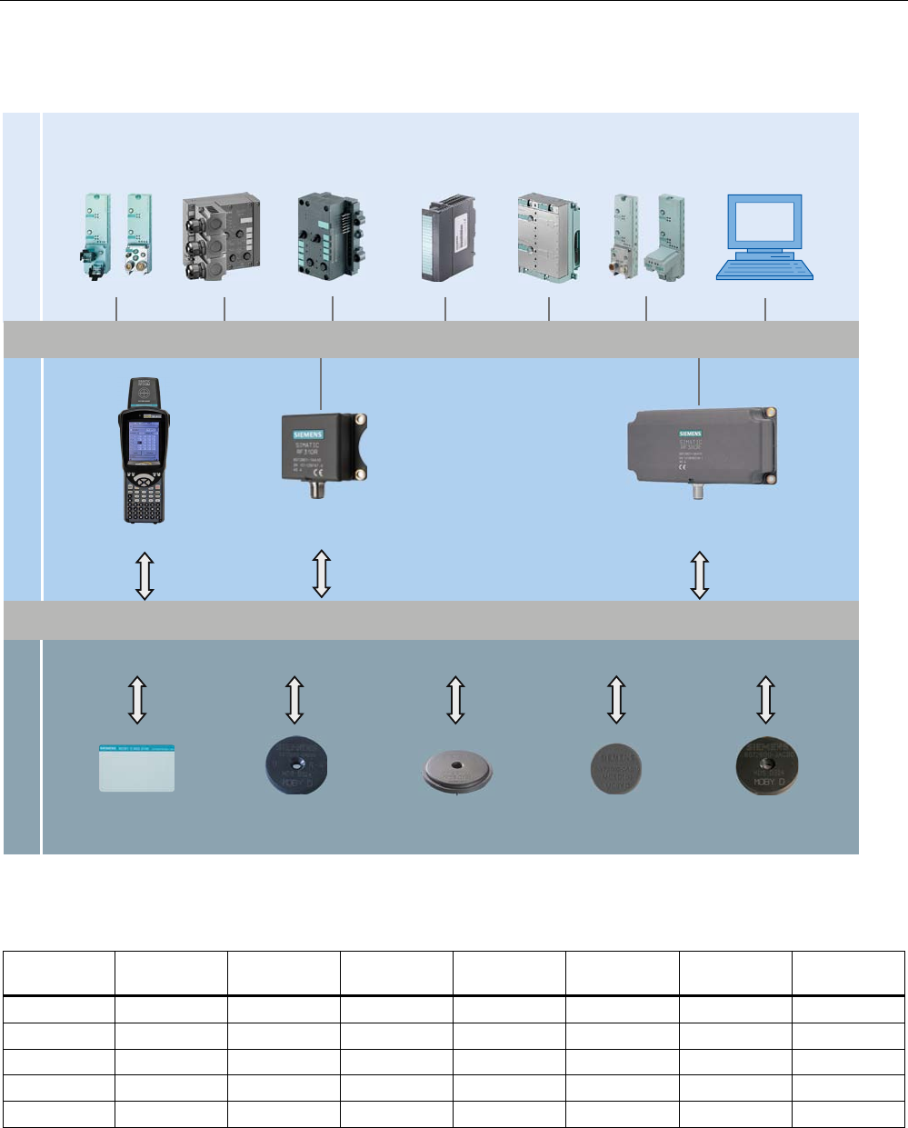
RF300 system components for low- and high-performance applications
7UDQVSRQGHU 5HDGHU &RPPXQLFDWLRQPRGXOHV
3RZHUDQGGDWDWUDQVPLVVLRQ0+]
6HULDODV\QFKURQRXVLQWHUIDFH56 5656
3&LQWHUIDFH
7KLUGSDUW\3/&
$60IRU
6,0$7,&6
5)&IRU
(7SUR
$60IRU
(7;
$60IRU
352),%86
'39
$60bIRU
352),%86'3
'39
5)&IRU
352),1(7,2
,46HQVH
LQWHUIDFH
[,46HQVHIRU
(70
2Q6
5)5
,46HQVH
5)7 5)7 5)7 5)7 5)7 5)7
5)5
5)0 5)5
5)5
5)5
Figure 3-1 System overview low- and high-performance
Table 3- 2 Reader-tag combination options for low- and high-performance applications
Tags/
MDS
RF310R
(IQ-Sense)
RF310R
(RS422)
RF340R RF350R with
ANT 1
RF350R with
ANT 18
RF350R with
ANT 30
RF380R
RF320T ✓ ✓ ✓ ✓ ✓ ✓ ✓
RF340T ✓ ✓ ✓ ✓ ✓ ✓ ✓
RF350T ✓ ✓ ✓ ✓ -- ✓ ✓
RF360T ✓ ✓ ✓ ✓ -- -- ✓
RF370T ○ ○ ✓ ✓ -- -- ✓
RF380T ○ ○ ✓ ✓ -- -- ✓
✓ Combination possible
-- Combination not approved
○ Combination possible, but not recommended
System overview
3.2 SIMATIC RF300
SIMATIC RF300
System Manual, 01/2009, A5E01642529-03 21
RF300 system components for medium-performance applications
5HDGHU &RPPXQLFDWLRQPRGXOHV
3RZHUDQGGDWDWUDQVPLVVLRQ0+]
6HULDODV\QFKURQRXVLQWHUIDFH56 5656
3&LQWHUIDFH
7KLUGSDUW\3/&
$60IRU
6,0$7,&6
5)&IRU
(7SUR
$60IRU
(7;
$60IRU
352),%86
'39
$60bIRU
352),%86'3
'39
5)&IRU
352),1(7,2
7UDQVSRQGHU
0'6'
0'6' 0'6' 0'6' 0'6'
5)0 5)5
5)5
Figure 3-2 System overview medium-performance
Table 3- 3 Reader-tag combination options for medium-performance applications
Tags/
MDS
RF310R
(IQ-Sense)
RF310R
(RS422)
RF340R RF350R with
ANT 1
RF350R with
ANT 18
RF350R with
ANT 30
RF380R
MDS D100 -- ✓ -- -- -- -- ✓
MDS D124 -- ✓ -- -- -- -- ✓
MDS D139 -- ○ -- -- -- -- ✓
MDS D160 -- ✓ -- -- -- -- ✓
MDS D324 -- ✓ -- -- -- -- ✓
✓ Combination possible
-- Combination not approved
○ Combination possible, but not recommended

System overview
3.2 SIMATIC RF300
SIMATIC RF300
22 System Manual, 01/2009, A5E01642529-03
Note
ISO15693 is only possible with MLFB 6GT2801-xxBxx readers.
Conventions
The RF310R, RF340R and RF380R readers are equipped with an integral antenna, whereas
the RF350R reader is operated over an external antenna. In this system manual, the term
"Reader" is used throughout even where it is actually referring to the antenna of the reader.
3.2.3 Application areas of RF300
SIMATIC RF300 is primarily used for non-contact identification of containers, palettes and
workpiece holders in a closed production circuit. The data carriers (transponders) remain in
the production chain and are not supplied with the products. SIMATIC RF300, with its
compact transponder and reader enclosure dimensions, is particularly suitable in confined
spaces.
Main applications
● Mechanical engineering, automation systems, conveyor systems
● Ancillary assembly lines in the automotive industry, component suppliers
● Small assembly lines
Application examples
● Production lines for engines, gearboxes, axles, etc.
● Assembly lines for ABS systems, airbags, brake systems, doors, cockpits, etc.
● Assembly lines for household electrical appliances, consumer electronics and electronic
communication equipment
● Assembly lines for PCs, small-power motors, contactors, switches
Advantages
● Reading and writing of large data volumes within a short time results in shorter production
cycle times and thus help to boost productivity
● Can be used in harsh environments thanks to rugged components with high degree of
protection
● Simple and low-cost system integration into SIMATIC S7 and PROFIBUS (TIA)
● Shorter commissioning times and fewer plant failures and downtimes thanks to integral
diagnostic functionalities
● Cost savings thanks to maintenance-free components

System overview
3.3 System configuration
SIMATIC RF300
System Manual, 01/2009, A5E01642529-03 23
3.3 System configuration
3.3.1 Overview
The SIMATIC RF300 system is characterized by a high level of standardization of its
components. This means that the system follows the TIA principle throughout: Totally
Integrated Automation. It provides maximum transparency at all levels with its reduced
interface overhead. This ensures optimum interaction between all system components.
The RF300 system with its flexible components offers many possibilities for system
configuration. This chapter shows you how you can use the RF300 components on the basis
of various example scenarios.
3.3.2 Assembly line example: Use of RF300 tags
In assembly lines, such as in engine manufacturing, many work steps are completed in
succession. Automated or manual assembly work is carried out at the individual workstations
in relatively short periods of time. The special features of the RF300 tags, which stand out for
their large data memory and high transmission speeds, bring about many advantages in
regard to the production unit numbers of such plants.
The possibility of saving large volumes of data means savings in terms of data management
on the HOST system and considerably contributes to data security. (redundant data
management, e.g. HOST database, or controller and data carrier)
Advantages at a glance:
● Redundant data storage on the basis of large memory, availability of decentralized data
● High data rate
● Data management savings on the host system
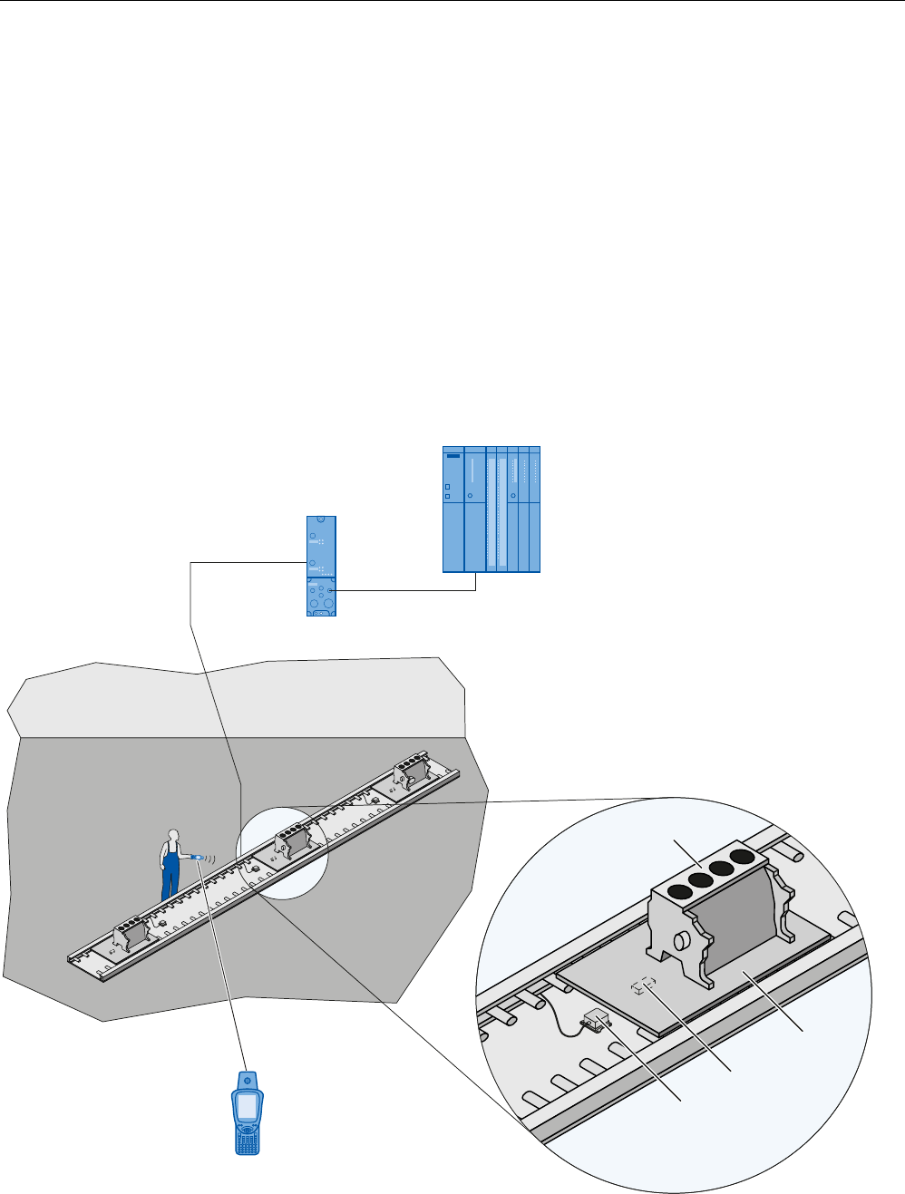
Characteristics of the scenario
In this example scenario, engine blocks that are placed on metal pallets are conveyed on an
assembly line. The engines are assembled piece-by-piece at the individual workstations. The
SIMATIC RF340T RFID tag is securely affixed on the underside of the pallet. The transport
speed is approx. 0.5 m/s.
System overview
3.3 System configuration
SIMATIC RF300
24 System Manual, 01/2009, A5E01642529-03
In this scenario, it is an advantage that the tag can be directly secured to metal on the metal
pallets. The small-dimensioned SIMATIC RF310R reader is integrated in the conveyor
elements in such a manner that it can communicate with the tags from below. Thus, it is not
necessary to align the pallets or to attach several tags.
The data of the entire production order (5000 bytes) is stored on the tag. This data is read at
each workstation and changed or supplemented depending on the workstation, and then
written back again. Thus, the status of the engine block assembly can be determined at any
point in time, even if there is a failure at the HOST level.
Thanks to the extremely high data rate, a very short cycle time for the work steps can be
factored in, which results in high end product unit numbers (engines).
The entire production order that is saved on the tag can also be manually read via the WIN-
LC terminal located at each workstation. This means that virtually no additional data
management is required on the control PC.
The production order data can also be read for servicing purposes via the mobile SIMATIC
RF310M handheld terminal.
0HWDOSDOOHW
(QJLQHEORFN
6,0$7,&6
FRQWUROOHU
+DQGKHOG
WHUPLQDO
5)0
$60
5)7
5)5
Figure 3-3 Example of engine block production

System overview
3.3 System configuration
SIMATIC RF300
System Manual, 01/2009, A5E01642529-03 25
3.3.3 Example of container and paper board container handling: Use of ISO tags
Containers of varying sizes are conveyed to picking workstations in a delivery center. There,
the individual goods are removed and packed in cartons according to the delivery note.
These cartons are marked with low-cost transponder labels and sorted to small or large
packaging workstations (according to the delivery note) by being guided or transported via
the corresponding conveyor system. The containers are marked using the MDS D100 ISO
tag.
Advantages at a glance:
● Decision points in the conveyor system can be installed in a more favorable way
(mechanically)
● Different sizes of containers with different depths can be identified due to the range
● In contrast to bar codes, tags can also be written to
● Different types of tags can be processed using one and the same reader
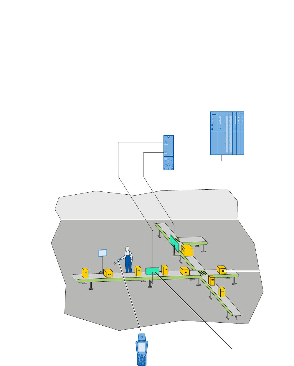
Characteristics of the scenario
In this example scenario, containers of varying sizes are conveyed on a conveyor system.
Only the unique identification number (8 bytes) is read. The containers to be picked are
sorted to the corresponding workstations. The maximum transport speed is 1.0 m/s.
System overview
3.3 System configuration
SIMATIC RF300
26 System Manual, 01/2009, A5E01642529-03
In this scenario, it is an advantage that the RF380R reader can read and write the tags at
different distances on the containers without a great deal of mechanical or control system
effort due to the reading range.
During the picking process, the goods are immediately placed in different containers or
packed in cartons depending on the destination (small packaging or large packaging station).
The containers are equipped with the MDS D100 ISO tag. The low-cost "one-way tag" (label)
is used on the cartons: it is simply glued onto the carton. Thus the goods can be identified at
any time. Again, one and the same reader is used for this. The maximum transport speed is
0.8 m/s.
In addition, flexible identification is possible at each location and at any time using the mobile
SIMATIC RF310M handheld terminal.
5)5UHDGHU
6,0$7,&6
FRQWUROOHU
+DQGKHOGWHUPLQDO
5)0
0'6'
$60
Figure 3-4 Example of container and paper board container handling

System overview
3.4 System data
SIMATIC RF300
System Manual, 01/2009, A5E01642529-03 27
3.4 System data
Table 3- 4
Type Inductive identification system for industrial applications
Transmission frequency data/energy 13.56 MHz
Memory capacity • 20 bytes to 64 KB user memory (r/w)
• 4 bytes fixed code as serial number (ro)
Memory type EEPROM / FRAM
Write cycles • EEPROM: > 200 000
• FRAM: Unlimited
Read cycles Unlimited
Data management Byte-by-byte access
RF300 tags ISO tags
Read approx. 8000 bytes/s approx. 600 bytes/s
Data transmission rate
Transponder reader
Write approx. 8000 bytes/s approx. 400 bytes/s
Read/write distance
(system limit; depends on reader and transponder)
• RF300 tags: up to 0.15 m
• ISO tags: up to 0.2 m
Readers:
-25 to +70 °C Operating temperature
Transponder:
-40 to +125 °C
+220 °C cyclically
Degree of protection Reader: IP 67 2)
Transponder: > IP 67
Can be connected to • SIMATIC S7-300
• PROFIBUS DP V1
• PROFINET
• PC 1)
• Third-party control 1)
Special features • High noise immunity
• Compact components
• Extensive diagnostic options
• A reader with IQ-Sense interface
• ISO 15693 functionality can be parameterized
Approvals • ETS 300 330 (Europe)
• FCC Part 15 (USA),
• UL/CSA CE,
• operating license for Japan
1) By means of RS422 interface and 3964R protocol
2) Exception RF350R: IP 65

System overview
3.4 System data
SIMATIC RF300
28 System Manual, 01/2009, A5E01642529-03
SIMATIC RF300
System Manual, 01/2009, A5E01642529-03 29
RF300 system planning 4
4.1 Fundamentals of application planning
4.1.1 Selection criteria for SIMATIC RF300 components
Assess your application according to the following criteria, in order to choose the right
SIMATIC RF300 components:
● Transmission distance (read/write distance)
● Tracking tolerances
● Static or dynamic data transfer
● Data volume to be transferred
● Speed in case of dynamic transfer
● Metal-free rooms for transponders and readers
● Ambient conditions such as relative humidity, temperature, chemical impacts, etc.
4.1.2 Transmission window and read/write distance
The reader generates an inductive alternating field. The field is strongest near to the reader.
The strength of the field decreases in proportion to the distance from the reader. The
distribution of the field depends on the structure and geometry of the antennas in the reader
and transponder.
A prerequisite for the function of the transponder is a minimum field strength at the
transponder achieved at a distance Sg from the reader or the ANT1. The picture below
shows the transmission window between transponder and reader or ANT1:
RF300 system planning
4.1 Fundamentals of application planning
SIMATIC RF300
30 System Manual, 01/2009, A5E01642529-03
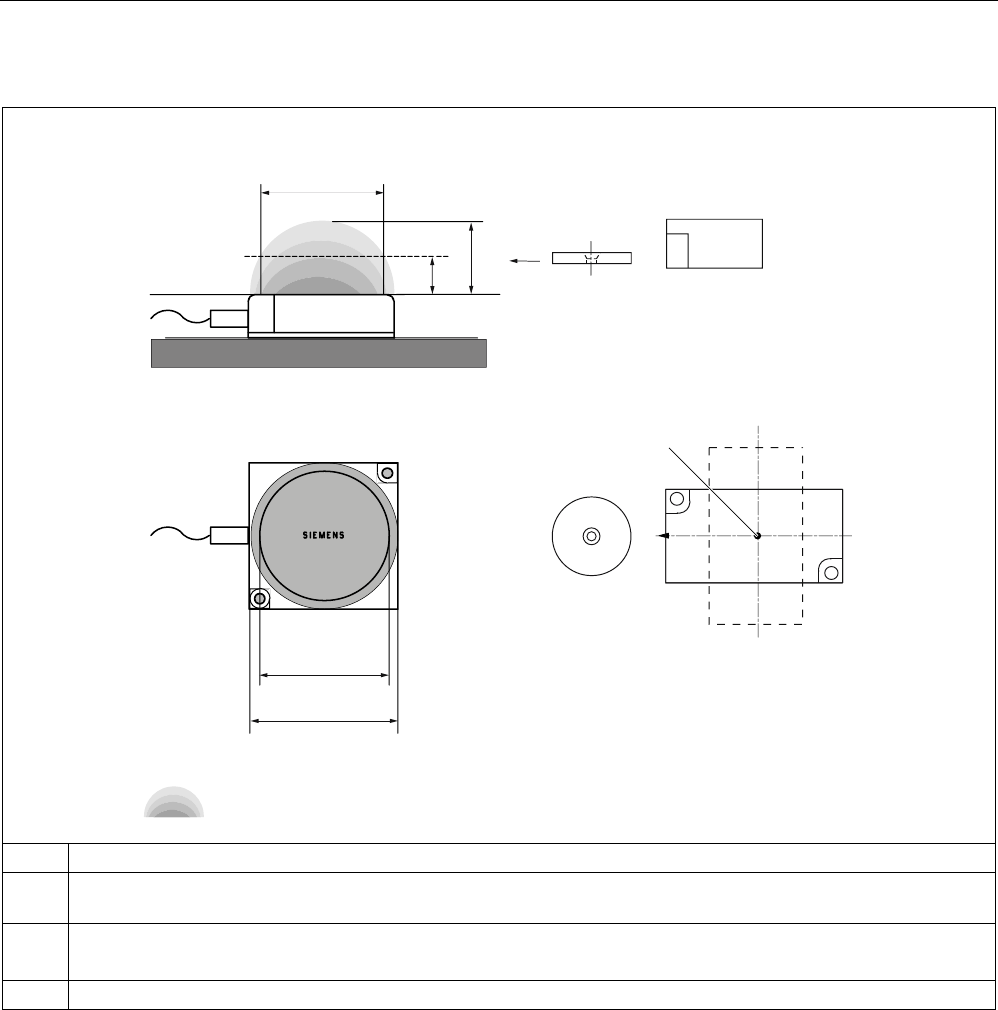
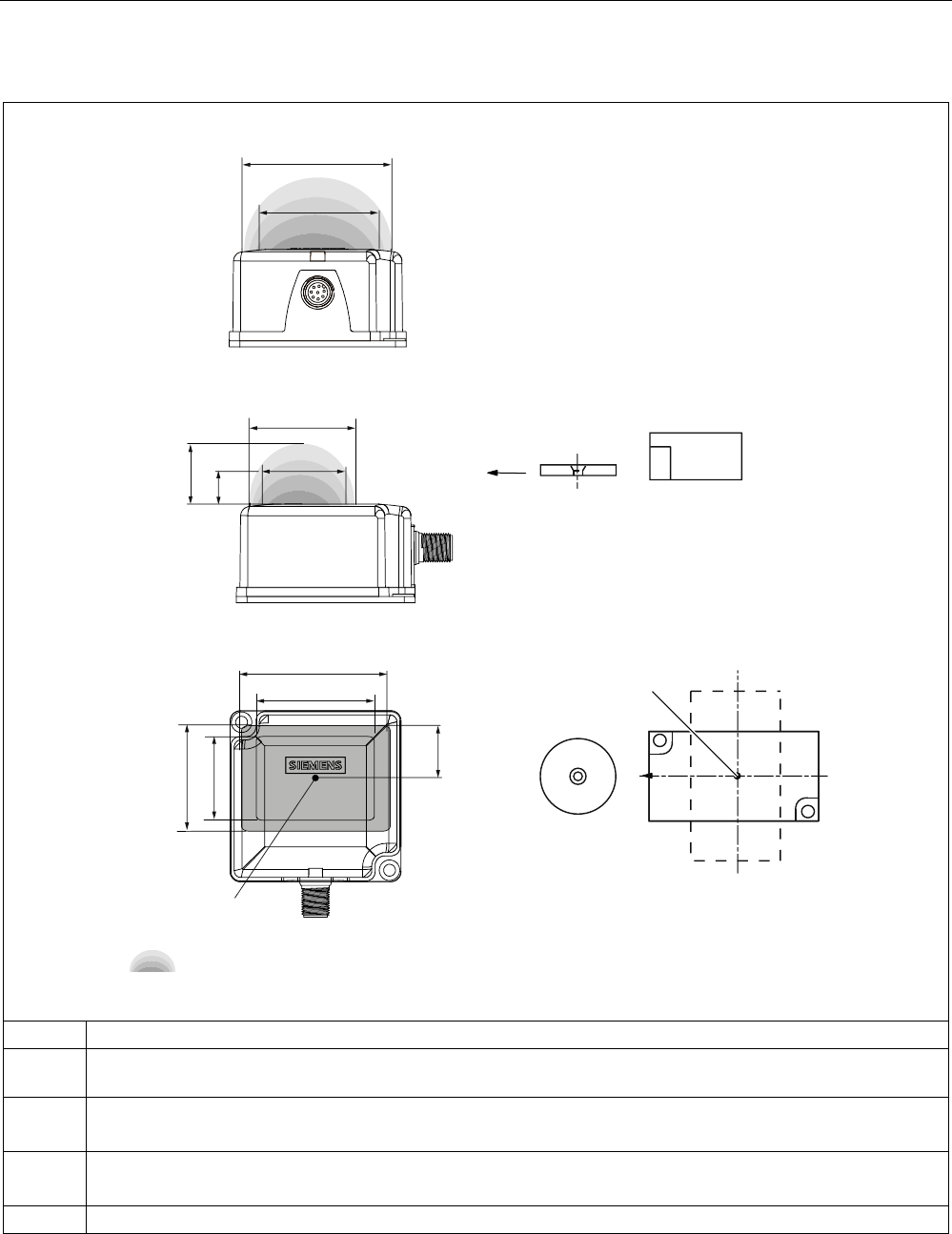
Table 4- 1 RF310R reader and ANT1 (RF350R) transmission window and read/write distance
3ODQYLHZ
6LGHYLHZ
7UDQVSRQGHU
7UDQVSRQGHU
7UDQVPLVVLRQZLQGRZ
63
6
J
6
D
/
'
/6
DPD[
/
G
/6
DPLQ
/
PD[
6,(0(16
6,0$7,&
5)7
5)7
Sa: Operating distance between transponder and reader
Sg Limit distance (maximum clear distance between upper surface of the reader and the transponder, at which the
transmission can still function under normal conditions)
L Length of a transmission window
The length Ld is valid for the calculation. At Sa,min , the field length increases from Ld to Lmax.
SP Intersection of the axes of symmetry of the transponder
RF300 system planning
4.1 Fundamentals of application planning
SIMATIC RF300
System Manual, 01/2009, A5E01642529-03 31
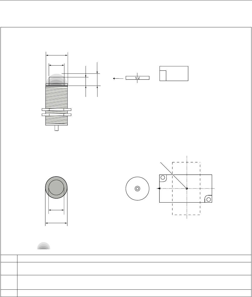
Table 4- 2 RF340R reader transmission window and read/write distance
7UDQVSRQGHU
7UDQVSRQGHU
63
3ODQYLHZ
7UDQVPLVVLRQZLQGRZ
6LGHYLHZ
)URQWYLHZ
s
0
/
[
PD[
/
\
PD[
/
[PD[
6
DPLQ
6
J
6
D
/
\
/
[
/
\PD[
6
DPLQ
/
[
/
\
6,(0(16
6,0$7,&
5)7
5)7
All dimensions in mm.
Sa: Operating distance between transponder and reader
Sg Limit distance (maximum clear distance between upper surface of the reader and the transponder, at which the
transmission can still function under normal conditions)
Lx Length of a transmission window in the x direction
The length Lx is valid for the calculation. At Sa,min , the field length increases from Lx to Lmax.
Ly Length of a transmission window in the y direction
The length Ly is valid for the calculation. At Sa,min , the field length increases from Ly to Ly max.
M Field centerpoint
RF300 system planning
4.1 Fundamentals of application planning
SIMATIC RF300
32 System Manual, 01/2009, A5E01642529-03
Table 4- 3 ANT18 and ANT30 (RF350R) transmission window and read/write distance
63
3ODQYLHZ
6LGHYLHZ
7UDQVPLVVLRQZLQGRZ
6,(0(16
7UDQVSRQGHU
6,0$7,&
5)7
7UDQVSRQGHU
5)7
/6DPD[ /G
6J
6D
/G
/6DPLQ /PD[
/PD[
Sa: Operating distance between transponder and reader
Sg Limit distance (maximum clear distance between upper surface of the reader and the transponder, at which the
transmission can still function under normal conditions)
L Diameter of a transmission window
The length Ld is valid for the calculation. At Sa,min , the field length increases from Ld to Lmax.
SP Intersection of the axes of symmetry of the transponder
RF300 system planning
4.1 Fundamentals of application planning
SIMATIC RF300
System Manual, 01/2009, A5E01642529-03 33
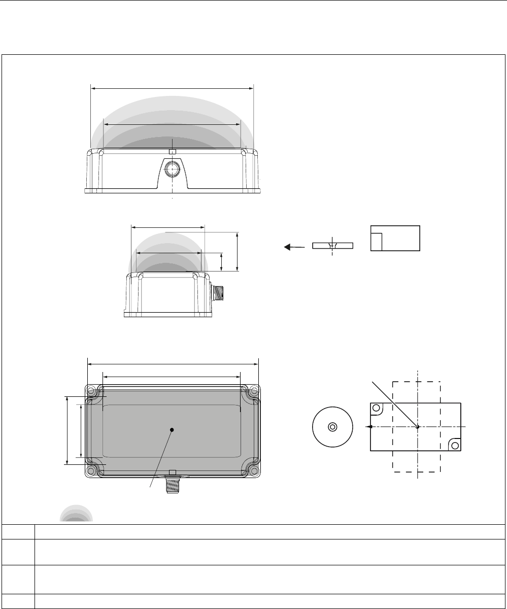
Table 4- 4 RF380R reader transmission window and read/write distance
3ODQYLHZ
)URQWYLHZ
6LGHYLHZ
7UDQVPLVVLRQZLQGRZ
7UDQVSRQGHU
7UDQVSRQGHU
63
/
\
6
J
6
D
/
[
/[PD[6DPLQ
/
\
6
DPLQ
/[PD[
/\PD[
/
\
/[
0
6,(0(16
6,0$7,&
5)7
5)7
Sa: Operating distance between transponder and reader
Sg Limit distance (maximum clear distance between upper surface of the reader and the transponder, at which the
transmission can still function under normal conditions)
L Length of a transmission window
The length LD is valid for the calculation. At Sa,min , the field length increases from LD to Lmax.
M Field centerpoint
The transponder can be used as soon as the intersection (SP) of the transponder enters the
area of the transmission window.
From the diagrams above, it can also be seen that operation is possible within the area
between Sa and Sg. The active operating area reduces as the distance increases, and
shrinks to a single point at distance Sg. Only static mode should thus be used in the area
between Sa and Sg.

RF300 system planning
4.1 Fundamentals of application planning
SIMATIC RF300
34 System Manual, 01/2009, A5E01642529-03
4.1.3 Width of the transmission window
Determining the width of the transmission window
The following approximation formula can be used for practical applications:
% y/
B: Width of the transmission window
L: Length of the transmission window
Tracking tolerances
The width of the transmission window (B) is particularly important for the mechanical tracking
tolerance. The formula for the dwell time is valid without restriction when B is observed.
RF300 system planning
4.1 Fundamentals of application planning
SIMATIC RF300
System Manual, 01/2009, A5E01642529-03 35
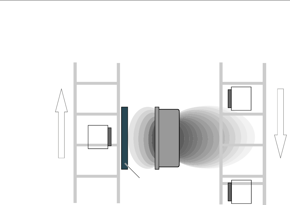
4.1.4 Impact of secondary fields
Secondary fields in the range from 0 to 20 mm always exist.
They should only be applied during planning in exceptional cases, however, since the
read/write distances are very limited. Exact details of the secondary field geometry cannot be
given, since these values depend heavily on the operating distance and the application.
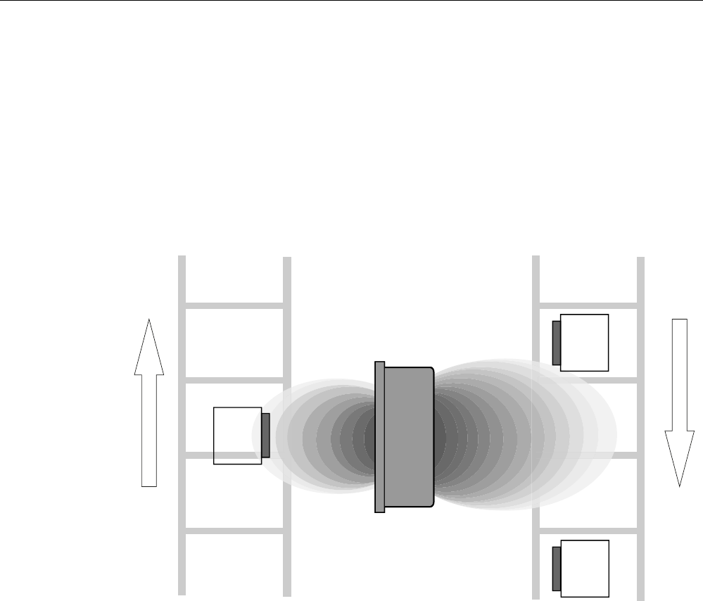
Secondary fields without shielding
The following graphic shows typical primary and secondary fields, if no shielding measures
are taken.
7DJ
6HFRQGDU\
ILHOG
0DLQILHOG
5HDGHU
7DJ
7DJ
&RQYH\LQJGLUHFWLRQ
&RQYH\LQJGLUHFWLRQ
Figure 4-1 Secondary field without shielding
In this arrangement, the reader can also read tags via the secondary field. Shielding is
required in order to prevent unwanted reading via the secondary field, as shown and
described in the following.
RF300 system planning
4.1 Fundamentals of application planning
SIMATIC RF300
36 System Manual, 01/2009, A5E01642529-03
Secondary fields with shielding
The following graphic shows typical primary and secondary fields, with metal shielding this
time.
The metal shielding prevents the reader from detecting tags via the secondary field.
5HDGHU
6HFRQGDU\
ILHOG
0DLQILHOG
0HWDOVKLHOGLQJ
7DJ
7DJ
7DJ
&RQYH\LQJGLUHFWLRQ
&RQYH\LQJGLUHFWLRQ
Figure 4-2 Secondary field with shielding
RF300 system planning
4.1 Fundamentals of application planning
SIMATIC RF300
System Manual, 01/2009, A5E01642529-03 37
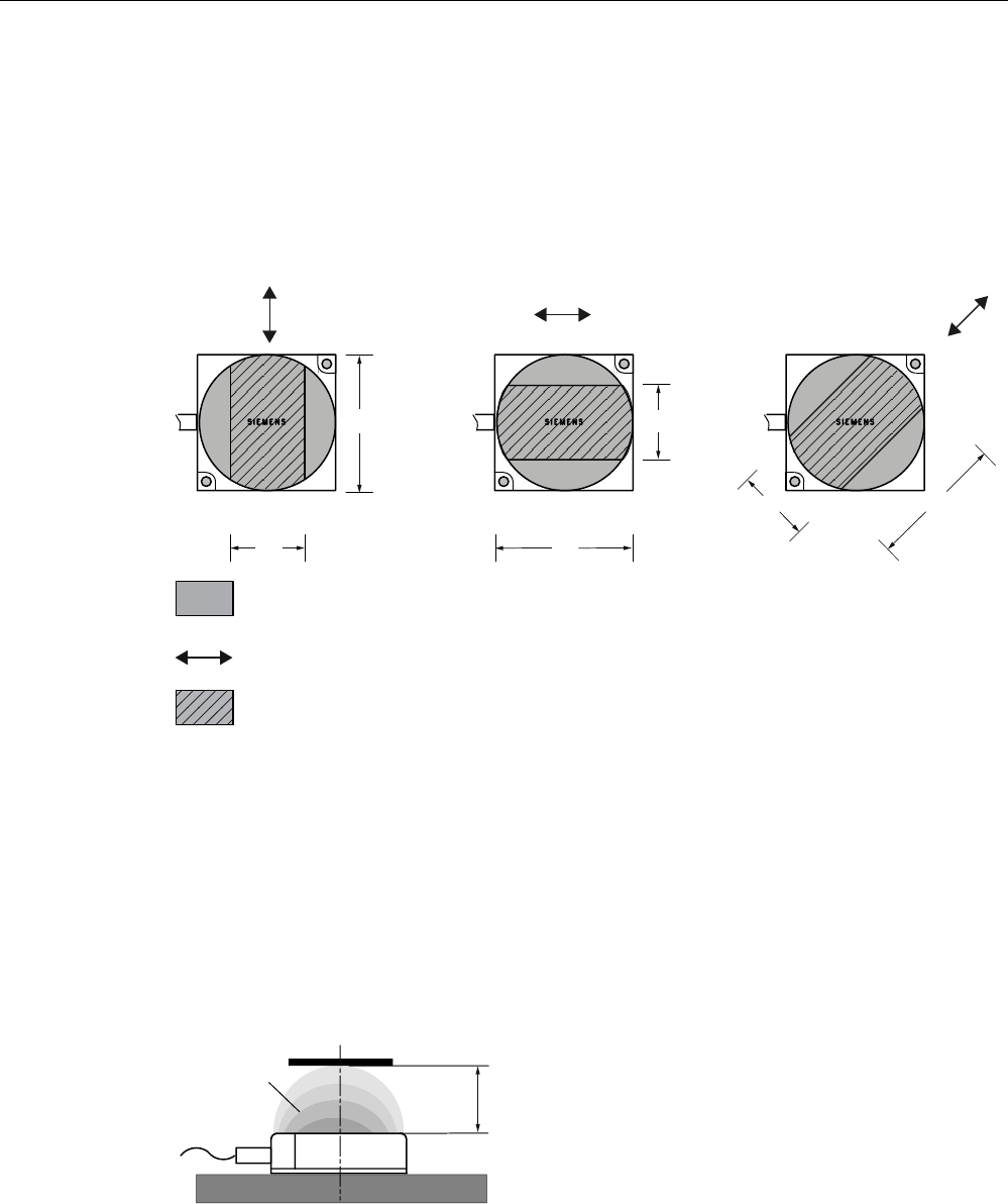
4.1.5 Permissible directions of motion of the transponder
Detection area and direction of motion of the transponder
The transponder and reader have no polarization axis, i.e. the transponder can come in from
any direction, be placed at any position, and cross the transmission window. The figure
below shows the active area for various directions of transponder motion:
%/
%
%/
/RGHU RGHU
Transmission window
Direction of motion of the transponder
Detection area L x W
Figure 4-3 Detection areas of the reader for different directions of transponder motion
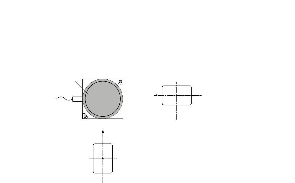
4.1.6 Operation in static and dynamic mode
Operation in static mode
If working in static mode, the transponder can be operated up to the limit distance (Sg). The
transponder must then be positioned exactly over the reader:
7UDQVPLVVLRQ
ZLQGRZ
7UDQVSRQGHU
5HDGHU
6
J
Figure 4-4 Operation in static mode
RF300 system planning
4.1 Fundamentals of application planning
SIMATIC RF300
38 System Manual, 01/2009, A5E01642529-03
Operation in dynamic mode
When working in dynamic mode, the transponder moves past the reader. The transponder
can be used as soon as the intersection (SP) of the transponder enters the circle of the
transmission window. In dynamic mode, the operating distance (Sa) is of primary importance.
[Operating distances, see Chapter Field data for transponders, readers and antennas
(Page 44)]
7UDQVPLVVLRQ
ZLQGRZ
7UDQVSRQGHU
7UDQVSRQGHU
3ODQYLHZ
63
63
Figure 4-5 Operation in dynamic mode

RF300 system planning
4.1 Fundamentals of application planning
SIMATIC RF300
System Manual, 01/2009, A5E01642529-03 39
4.1.7 Dwell time of the transponder
The dwell time is the time in which the transponder remains within the transmission window
of a reader. The reader can exchange data with the transponder during this time.
The dwell time is calculated thus:
0,8 [ ]
[/]
Tag
v
L m
tv m s
⋅
=
tV: Dwell time of the transponder
L: Length of the transmission window
vTag: Speed of the transponder (tag) in dynamic mode
0,8: Constant factor used to compensate for temperature impacts and production
tolerances
The dwell time can be of any duration in static mode. The dwell time must be sufficiently long
to allow communication with the transponder.
The dwell time is defined by the system environment in dynamic mode. The volume of data
to be transferred must be matched to the dwell time or vice versa. In general:
K
v
tt≥
tV:: Dwell time of the data memory within the field of the reader
tK: Communication time between transponder and communication module

RF300 system planning
4.1 Fundamentals of application planning
SIMATIC RF300
40 System Manual, 01/2009, A5E01642529-03
4.1.8 Communication between communication module, reader and transponder
Communication between the communication module, reader and transponder takes place
asynchronously through the RS422 interface. Depending on the communication module
(ASM) used, transfer rates of 19200 baud, 57600 baud or 115200 baud can be selected.
Calculation of the communication time for interference-free transfer
The communication time for fault-free data transfer is calculated as follows:
=+ ⋅tKtn
KByte
(n >1)
If the transmission is interrupted briefly due to external interference, the communication
module automatically continues the command.
Calculation of the maximum amount of user data
The maximum amount of user data is calculated as follows:
tk: Communication time between communication module, reader and transponder
tv: Dwell time
n: Amount of user data in bytes
nmax: Max. amount of user data in bytes in dynamic mode
tbyte: Transmission time for 1 byte
K
: Constant; the constant is an internal system time. This contains the time for power
buildup on the transponder and for command transfer

RF300 system planning
4.1 Fundamentals of application planning
SIMATIC RF300
System Manual, 01/2009, A5E01642529-03 41
Time constants K and tbyte for medium and high-performance applications
Table 4- 5 Static mode
RF300 mode
FRAM
ISO mode
Read/write Read Write
Data volume
≤ 233 bytes
Data volume
>233 bytes
Data volume
≤ 233 bytes
Data volume
>233 bytes
Independent of data
volume
Transfer rate
[baud]
K
[ms]
tbyte
[ms]
K
[ms]
tbyte
[ms]
K
[ms]
tbyte
[ms]
K
[ms]
tbyte
[ms]
K
[ms]
tbyte
[ms]
19200 28 0.67 28 0.67 35 1.08 64 0.75 41 2.66
57600 15 0.30 25 0.22 34 0.59 34 0.59 28 2.28
115200 11 0.21 30 0.12 26 0.56 26 0.56 26 2.17
The values for K and tbyte include the overall time that is required for communication in static mode. It is built up from
several different times:
• Serial communication between communication module, reader and
• Processing time between reader and transponder and their internal processing time.
The values shown in the table must be used when calculating the maximum quantity of user data in static mode. They are
applicable for both reading and writing in the FRAM area.
For writing in the EEPROM area (max. 20 bytes), the byte time tByte is approx. 11 ms.
Table 4- 6 Dynamic mode
RF300 tags ISO tags
Transfer rate
[baud]
Memory area
K [ms] tbyte [ms] K [ms] tbyte [ms]
Independent FRAM 8 0.13 - -
Independent
Write
Read
EEPROM
8
8
12.20
0.13
15
12
1.99
0.56
In dynamic mode, the values for K and tbyte are independent of the transmission speed. The
communication time only includes the processing time between the reader and the
transponder and the internal system processing time of these components. The
communication times between the communication module and the reader do not have to be
taken into account because the command for reading or writing is already active when the
transponder enters the transmission field of the reader.
The values shown above must be used when calculating the maximum quantity of user data
in dynamic mode. They are applicable for both writing and reading.
Time constants K and tbyte for low-performance applications (IQ-Sense)
Table 4- 7 Static mode
K (ms) tbyte (ms) Command
15 15 Read (FRAM/EEPROM area)
15 15 Write (FRAM area)
30 30 Write (EEPROM area)
The table of time constants applies to every command. If a user command consists of
several subcommands, the above tK formula must be applied to each subcommand.

RF300 system planning
4.1 Fundamentals of application planning
SIMATIC RF300
42 System Manual, 01/2009, A5E01642529-03
4.1.9 Calculation example (RS422)
A transport system moves pallets with transponders at a maximum velocity of VTag = 1.0 m/s
(dynamic mode). The following RFID components were selected:
● ASM 475 communication module
● RF310R reader with RS422 interface
● Transponder RF340T
Task
a) The designer of the plant is to be given mechanical specifications.
b) The programmer should be given the maximum number of bytes in dynamic mode.
Refer to the tables in the "Field data of transponders and readers" section for the technical
data.
Determine tolerance of pallet transport height
'LUHFWLRQRIPRWLRQ
7UDQVSRQGHU
VLGHYLHZ
++6
D
+PP
5HDGHUV
Figure 4-6 Tolerance of pallet transport height
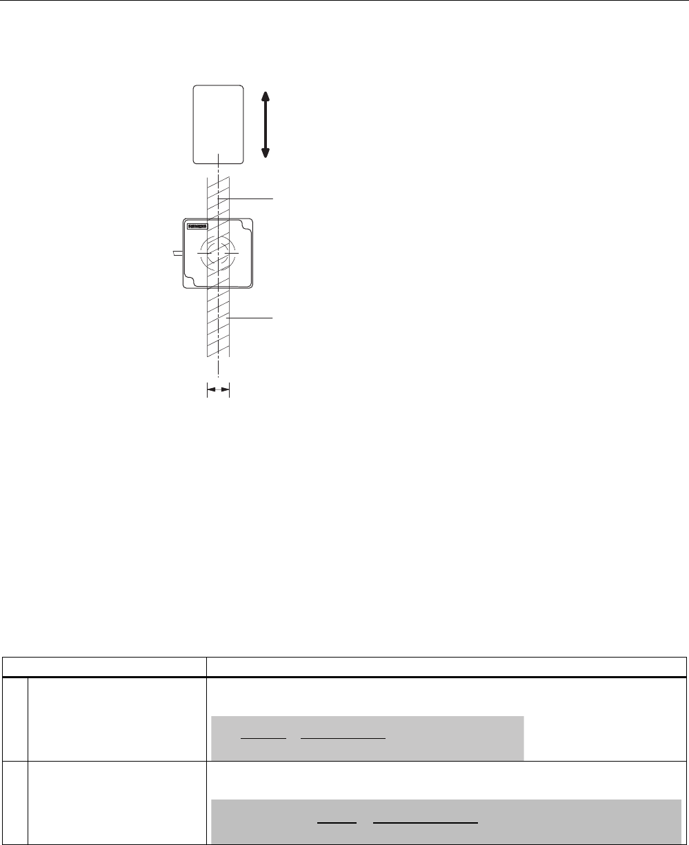
RF300 system planning
4.1 Fundamentals of application planning
SIMATIC RF300
System Manual, 01/2009, A5E01642529-03 43
Determine tolerance of pallet side transport
&HQWHUOLQHRIWUDQVSRQGHUDQGUHDGHU
'LUHFWLRQRIPRWLRQRIWKHWUDQVSRQGHU
% ZLGWKRIWKHWUDQVPLVVLRQZLQGRZ
LQG\QDPLFPRGH
%
7ROHUDQFHEDQGRIVLGHWUDQVSRUW
7UDQVSRQGHU
5HDGHUV
Figure 4-7 Tolerance of pallet side transport
Minimum distance from reader to reader
Refer to the field data of the reader for this value.
Minimum distance from transponder to transponder
Refer to the field data of the transponder for this value.
Calculation of the maximum amount of user data in dynamic mode
Step Formula/calculation
1. Calculate dwell time of the
transponder
Refer to the "Field data of all transponders and readers" table for value L.
Value vTag = 1.00 m/s
/ವ
Y
7DJ
Pವ
PV
W
Y
V PV
2. Calculate maximum user data
(nmax) for reading or writing
(FRAM area)
Take value tv from Step 1.
Take values K and t Byte from Table "Time constants K and t Byte".
5HDGZULWH QPD[ปE\WHVE\WHV
WE\WHV
WY.
PV
PVPV
ය
Result
A maximum of 172 bytes can be read or written when the transponder passes by.

RF300 system planning
4.2 Field data for transponders, readers and antennas
SIMATIC RF300
44 System Manual, 01/2009, A5E01642529-03
4.2 Field data for transponders, readers and antennas
The following table shows the field data for all SIMATIC RF300 components of transponders
and readers. It facilitates the correct selection of a transponder and reader.
All the technical specifications listed are typical data and are applicable for an ambient
temperature of between 0 C and +50 °C, a supply voltage of between 22 V and 27 V DC and
a metal-free environment. Tolerances of ±20 % are admissible due to production or
temperature conditions.
If the entire voltage range at the reader of 20 V DC to 30 V DC and/or the entire temperature
range of transponders and readers is used, the field data are subject to further tolerances.
Note
Transmission gaps
If the minimum operating distance (Sa) is not observed, a transmission gap can occur in the
center of the field. Communication with the transponder is not possible in the transmission
gap.
4.2.1 Field data of RF300 transponders
Observe the following information for field data of RF300 transponders:
● A maximum median deviation of ±2 mm is possible in static mode (without affecting the
field data)
● The field data are reduced by approx. 15% if the transponder enters the transmission
window laterally (see also "Transmission window" figure)
RF310R reader
Table 4- 8 RF310R reader
RF320T RF340T RF350T RF360T RF370T RF380T
Length of the
transmission window
(L)
30 38 45 45
Operating distance (Sa) 2...10 2...20 5...22 [26] 5...26
Limit distance (Sg) 16 26 30 [35] 35
Combination with the
RF310R is basically possible,
but is not recommended
because the antenna
geometries for the reader
and transponder are not
ideally matched.
All values are in mm
Values in brackets [ ] refer to RF310R with the MLFB 6GT2801-1AB10

RF300 system planning
4.2 Field data for transponders, readers and antennas
SIMATIC RF300
System Manual, 01/2009, A5E01642529-03 45
RF340R reader
Table 4- 9 RF340R reader
RF320T RF340T RF350T RF360T RF370T RF380T
Length of the
transmission window
(Lx)
45 60 60 70 75 85
Width of the
transmission window
(Ly)
40 45 50 60 65 75
Operating distance (Sa) 2...20 5...25 5...35 8...40 15...36 15...47
Limit distance (Sg) 25 35 50 60 52 55
All values are in mm
RF350R reader / ANT 1
Table 4- 10 RF350R reader / ANT 1
RF320T RF340T RF350T RF360T RF370T RF380T
Length of the
transmission window
(L)
45 60 60 70 70 88
Operating distance (Sa) 2...20 5...25 5...35 8...40 15...45 15...53
Limit distance (Sg) 25 35 50 60 65 65
All values are in mm
RF350R reader / ANT 18
Table 4- 11 RF350R reader / ANT 18
RF320T RF340T RF350T RF360T RF370T RF380T
Diameter of the
transmission window
(Ld)
10 20
Operating distance (Sa) 2...8 2...10
Limit distance (Sg) 10 13
Not yet released
All values are in mm

RF300 system planning
4.2 Field data for transponders, readers and antennas
SIMATIC RF300
46 System Manual, 01/2009, A5E01642529-03
RF350R reader / ANT 30
Table 4- 12 RF350R reader / ANT 30
RF320T RF340T RF350T RF360T RF370T RF380T
Diameter of the
transmission window
(Ld)
15 25 25
Operating distance (Sa) 2...11 5...15 5...16
Limit distance (Sg) 15 20 22
Not yet released
All values are in mm
RF380R reader
Table 4- 13 RF380R reader
RF320T RF340T RF350T RF360T RF370T RF380T
Length of the
transmission window
(Lx)
100 115 120 120 135 155
Width of the
transmission window
(Ly)
40 50 60 70 65 75
Operating distance (Sa) 2...30 [40] 20...70 [80] 35...70 [100] 40...120 35...85 [100] 25...85 [110]
Limit distance (Sg) 47 [55] 90 [100] 105 [130] 140 [150] 125 [135] 125 [140]
All values are in mm
Values in brackets [ ] refer to RF380R with the MLFB 6GT2801-3AB10
The RF380R with MLFB 6GT2801-3AB10 gives the user the capability of setting the
transmission output power with the aid of the "dili" (distance limiting) input parameter. For
this, values from approx. 0.5 W to approx. 2.0 W can be set in 0.25 W increments.
Depending on the setting, the change to the transmission output power increases the
performance in the lower operating distance (low performance) or in the upper limit distance
(high performance).
The "dili" value range goes from
02 (= 0.5 W) and
05 (default value: 1.25 W) to
08 (= 2 W).
Note
A dili value setting outside of the value range of 02 to 08 leads to the default setting (05) and
does not generate an error message.
Also see Chapter Minimum clearances (Page 48) Section "Minimum distance from reader to
reader".
You can find exact information regarding the parameters in the Product Information "FB 45
and FC 45 input parameters for RF300 and ISO transponders"
(http://support.automation.siemens.com/WW/view/en/33315697).

RF300 system planning
4.2 Field data for transponders, readers and antennas
SIMATIC RF300
System Manual, 01/2009, A5E01642529-03 47
4.2.2 Field data of ISO transponders
Observe the following information for field data of ISO transponders:
● A maximum median deviation of ±2 mm is possible in static mode (without affecting the
field data)
● The field data are reduced by approx. 15% if the transponder enters the transmission
window laterally (see also "Transmission window" figure)
RF310R reader
Table 4- 14 RF310R reader
MDS D100 MDS D124 MDS D139 MDS D160 MDS D324
Length of the transmission
window (L)
50 30 36 40
Operating distance (Sa) 2...78 2...22 2...25 2...30
Limit distance (Sg) 90 30
1)
37 38
All values are in mm
1) Combination with the RF310R is basically possible, but is not recommended because the antenna geometries for the
reader and transponder are not ideally matched.
RF380R reader
Table 4- 15 RF380R reader
MDS D100 MDS D124 MDS D139 MDS D160 MDS D324
Length of the transmission
window (Lx)
160 100 155 120 130
Width of the transmission
window (Ly)
100 80 90 40 60
Operating distance (Sa) 15…170 0…72 15...160 0…64 0…96
Limit distance (Sg) 210 90 200 80 120
All values are in mm
Only the MDS D139 with MLFB 6GT2600-0AA10 is compatible with SIMATIC RF300.

RF300 system planning
4.2 Field data for transponders, readers and antennas
SIMATIC RF300
48 System Manual, 01/2009, A5E01642529-03
4.2.3 Minimum clearances
Minimum distance from transponder to transponder
The specified distances refer to a metal-free environment. For a metallic environment, the
specified minimum distances must be multiplied by a factor of 1.5.
Table 4- 16 RF300 tags
Readers
RF320T RF340T RF350T RF360T RF370T RF380T
RF310R ≥ 50 ≥ 60 ≥ 60 ≥ 60 n.a. n.a.
RF340R ≥ 70 ≥ 80 ≥ 80 ≥ 80 ≥ 80 ≥ 80
RF350R, ANT1 ≥ 70 ≥ 80 ≥ 80 ≥ 80 ≥ 80 ≥ 80
RF350R, ANT18 ≥ 20 ≥ 40 n.a. n.a. n.a. n.a.
RF350R, ANT30 ≥ 40 ≥ 40 ≥ 50 n.a. n.a. n.a.
RF380R ≥ 120 ≥ 140 ≥ 150 ≥ 120 ≥ 130 ≥ 150
The values are all in mm, relative to the operating distance (Sa) between reader and tag
Table 4- 17 ISO tags
Readers MDS D100 MDS D124 MDS D139 MDS D160 MDS D234
RF310R ≥ 120 ≥ 100 ≥ 120 ≥ 120 ≥ 120
RF380R ≥ 300 ≥ 170 ≥ 230 ≥ 150 ≥ 250
The values are all in mm, relative to the operating distance (Sa) between reader and tag
Minimum distance from reader to reader
RF310R to RF310R RF340R to RF340R RF380R to RF380R1)
≥ 100 ≥ 200 ≥ 400
All values are in mm
1) The permissible minimum distance between two RF380Rs depends on the transmission output
power that is set. The specified minimum distance must be multiplied by the following factor,
depending on the output:
DILI byte Factor
02; 03 0.8
04; 05; 06 1.0
07; 08 1.2

RF300 system planning
4.2 Field data for transponders, readers and antennas
SIMATIC RF300
System Manual, 01/2009, A5E01642529-03 49
Minimum distance from antenna to antenna
ANT1 ANT18 ANT30
≥ 100 ≥ 100 ≥ 100
All values are in mm
See also Minimum distance between antennas (Page 117)
NOTICE
Effect on inductive fields by not maintaining the minimum distances of the readers
When the values specified in the "minimum distance from reader to reader" table are not
met, there is a risk of affecting inductive fields. In this case, the data transfer time would
increase unpredictably or a command would be aborted with an error.
Adherence to the values specified in the "Minimum distance from reader to reader" table is
therefore essential.
If the specified minimum distance cannot be complied with due to the physical configuration,
the SET-ANT command can be used to activate and deactivate the HF field of the reader.
The application software must be used to ensure that only one reader is active (antenna is
switched on) at a time.
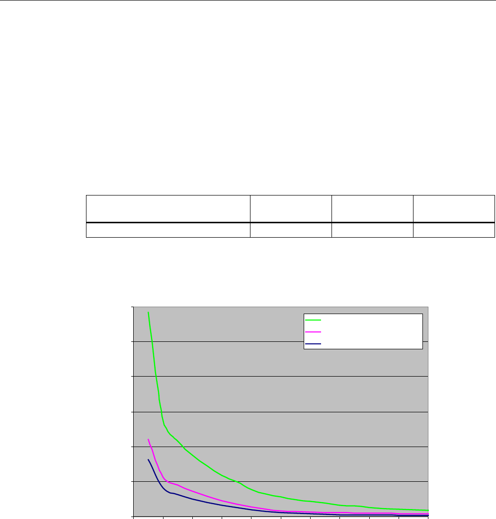
RF300 system planning
4.3 Dependence of the volume of data on the transponder speed with RF300 tags
SIMATIC RF300
50 System Manual, 01/2009, A5E01642529-03
4.3 Dependence of the volume of data on the transponder speed with
RF300 tags
The curves seen here show the relation between speed and data transfer volume for each
transponder. They should make it easier to preselect the transponders for dynamic use.
4.3.1 RF320T with RF310R, RF340R, RF350R, RF380R
The following table is used to calculate the curves.
The indicated speeds are applicable for operation without presence check.
RF310R RF340R/
RF350R
RF380R
Operating distance (Sa) 10 mm 10 mm 40 mm
RF320T: Display of speed relative to data volume (write)
5)5
5)5
5)55)5$17
%\WH
YPV
Figure 4-8 RF320T with RF310R, RF340R/RF350R, RF380R
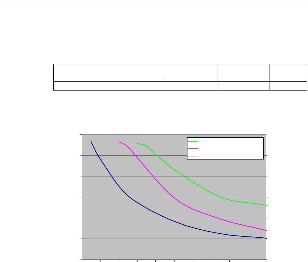
RF300 system planning
4.3 Dependence of the volume of data on the transponder speed with RF300 tags
SIMATIC RF300
System Manual, 01/2009, A5E01642529-03 51
4.3.2 RF340T with RF310R, RF340R, RF350R, RF380R
The following table is used to calculate the curves.
The indicated speeds are applicable for operation without presence check.
RF310R RF340R/
RF350R
RF380R
Operating distance (Sa) 20 mm 20 mm 40 mm
RF340T: Display of speed relative to data volume (read/write)
%\WH
YPV
5)5
5)5
5)55)5$17
Figure 4-9 RF340T with RF310R, RF340R/RF350R and RF380R
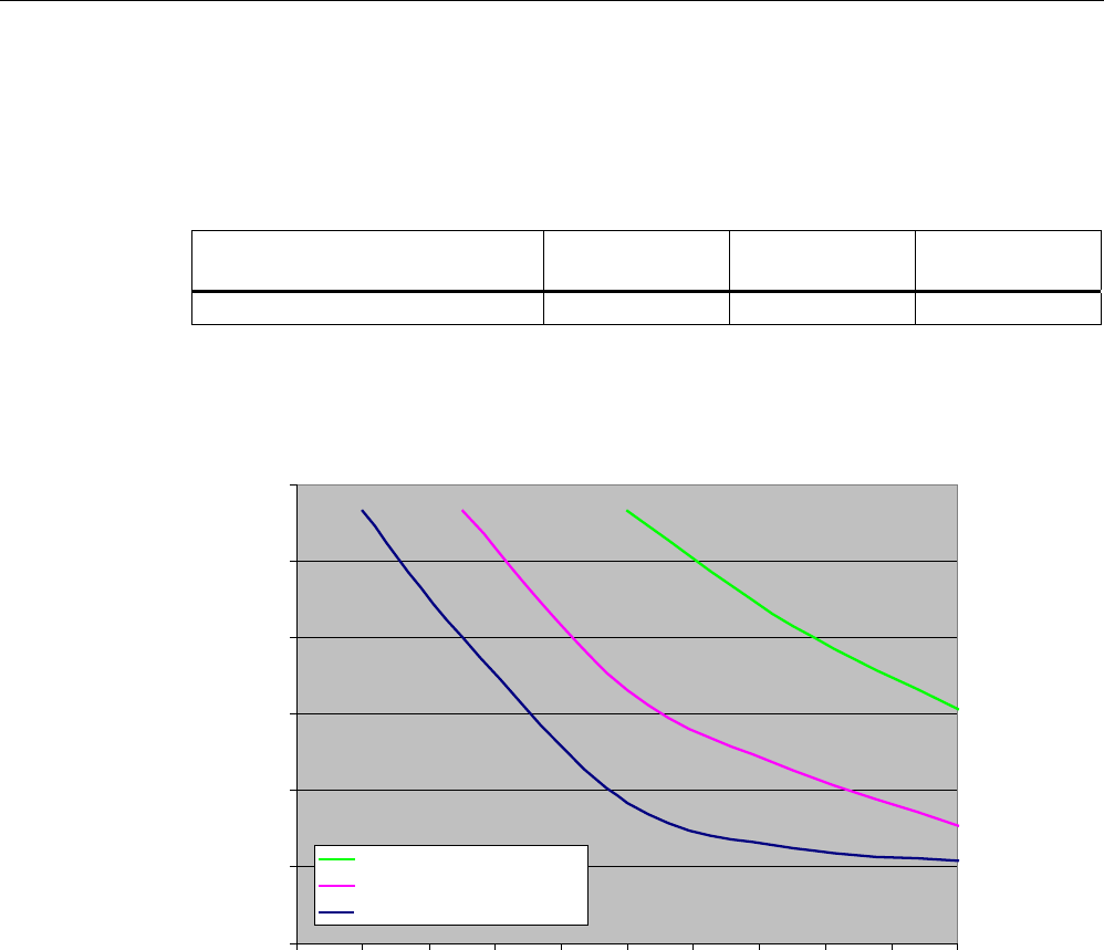
RF300 system planning
4.3 Dependence of the volume of data on the transponder speed with RF300 tags
SIMATIC RF300
52 System Manual, 01/2009, A5E01642529-03
4.3.3 RF350T with RF310R, RF340R, RF350R, RF380R
The following table is used to calculate the curves.
The indicated speeds are applicable for operation without presence check.
RF310R RF340R/
RF350R
RF380R
Operating distance (Sa) 22 mm 22 mm 40 mm
RF350T: Display of speed relative to data volume (read/write)
%\WH
YPV
5)5
5)5
5)55)5$17
Figure 4-10 RF350T with RF310R, RF340R/RF350R and RF380R
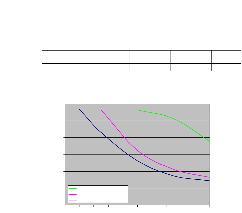
RF300 system planning
4.3 Dependence of the volume of data on the transponder speed with RF300 tags
SIMATIC RF300
System Manual, 01/2009, A5E01642529-03 53
4.3.4 RF360T with RF310R, RF340R, RF350R, RF380R
The following table is used to calculate the curves.
The indicated speeds are applicable for operation without presence check.
RF310R RF340R/
RF350R
RF380R
Operating distance (Sa) 26 mm 26 mm 60 mm
RF360T: Display of speed relative to data volume (read/write)
5)5
5)5
5)55)5$17
%\WH
YPV
Figure 4-11 RF360T with RF310R, RF340R/RF350R and RF380R
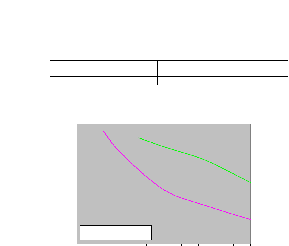
RF300 system planning
4.3 Dependence of the volume of data on the transponder speed with RF300 tags
SIMATIC RF300
54 System Manual, 01/2009, A5E01642529-03
4.3.5 RF370T with RF340R, RF350R, RF380R
The following table is used to calculate the curves.
The indicated speeds are applicable for operation without presence check.
RF340R/
RF350R
RF380R
Operating distance (Sa) 22 mm 60 mm
RF370T: Display of speed relative to data volume (read/write)
5)5
5)55)5$17
%\WH
YPV
Figure 4-12 RF370T with RF340R/RF350R and RF380R
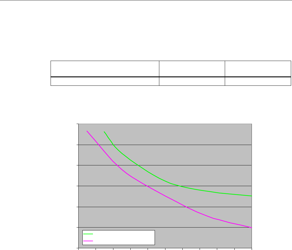
RF300 system planning
4.3 Dependence of the volume of data on the transponder speed with RF300 tags
SIMATIC RF300
System Manual, 01/2009, A5E01642529-03 55
4.3.6 RF380T with RF340R, RF350R, RF380R
The following table is used to calculate the curves.
The indicated speeds are applicable for operation without presence check.
RF340R/
RF350R
RF380R
Operating distance (Sa) 22 mm 60 mm
RF380T: Display of speed relative to data volume (read/write)
5)5
5)55)5$17
%\WH
YPV
Figure 4-13 RF380T with RF340R/RF350R and RF380R
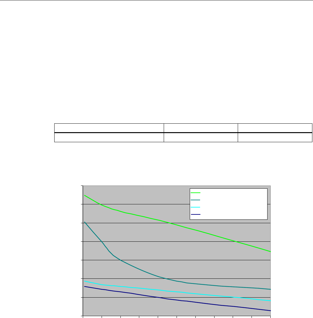
RF300 system planning
4.4 Dependence of the volume of data on the transponder speed with ISO tags
SIMATIC RF300
56 System Manual, 01/2009, A5E01642529-03
4.4 Dependence of the volume of data on the transponder speed with ISO
tags
The curves seen here show the relation between speed and data transfer volume for each
transponder. They should make it easier to preselect the transponders for dynamic use.
4.4.1 MDS D100 with RF310R and RF380R
The following table is used to calculate the curves.
The indicated speeds are applicable for operation without presence check.
RF310R RF380R
Operating distance (Sa) 30 mm 30 mm
MDS D100: Display of speed relative to data volume (read/write)
%\WH
YPV
5HDG5)5
5HDG5)5
:ULWH5)5
:ULWH5)5
Figure 4-14 MDS D100 with RF310R and RF380R
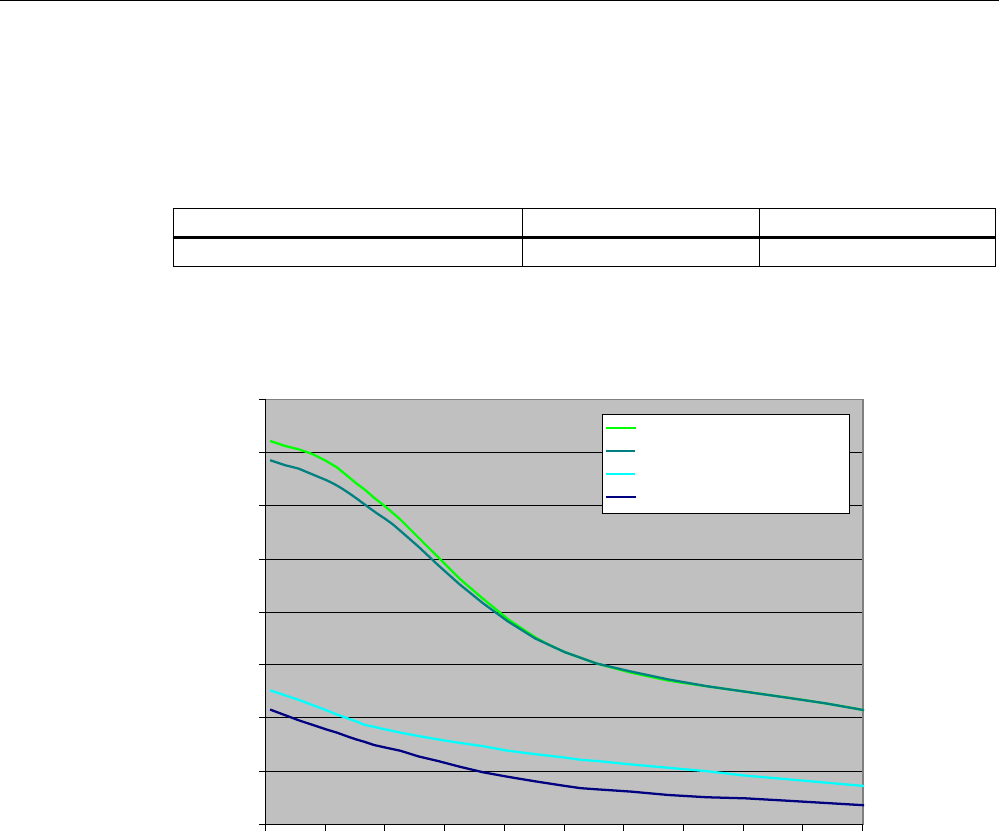
RF300 system planning
4.4 Dependence of the volume of data on the transponder speed with ISO tags
SIMATIC RF300
System Manual, 01/2009, A5E01642529-03 57
4.4.2 MDS D124 with RF310R and RF380R
The following table is used to calculate the curves.
The indicated speeds are applicable for operation without presence check.
RF310R RF380R
Operating distance (Sa) 25 mm 40 mm
MDS D124: Display of speed relative to data volume (read/write)
5HDG5)5
5HDG5)5
:ULWH5)5
:ULWH5)5
%\WH
YPV
Figure 4-15 MDS D124 with RF310R and RF380R
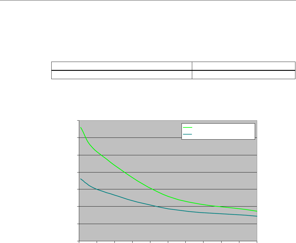
RF300 system planning
4.4 Dependence of the volume of data on the transponder speed with ISO tags
SIMATIC RF300
58 System Manual, 01/2009, A5E01642529-03
4.4.3 MDS D139 with RF310R and RF380R
The following table is used to calculate the curves.
The indicated speeds are applicable for operation without presence check.
RF380R
Operating distance (Sa) 60 mm
MDS D139: Display of speed relative to data volume (read/write)
%\WH
YPV
5HDG5)5
:ULWH5)5
Figure 4-16 MDS D139 with RF310R and RF380R
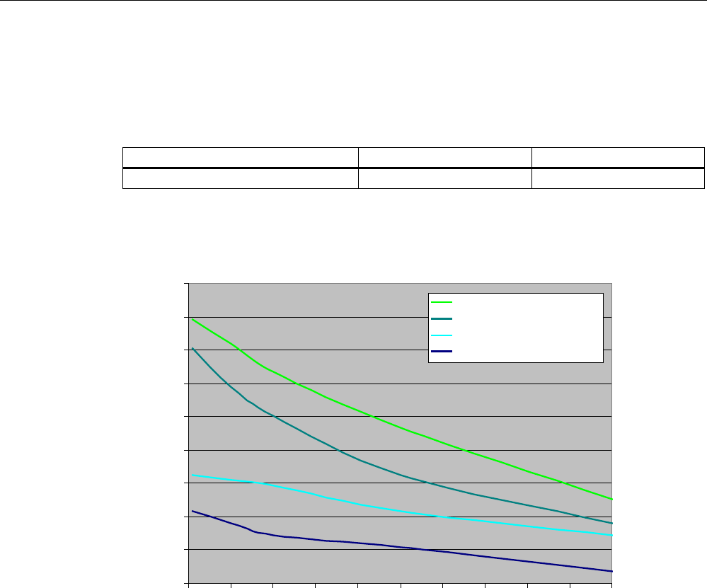
RF300 system planning
4.4 Dependence of the volume of data on the transponder speed with ISO tags
SIMATIC RF300
System Manual, 01/2009, A5E01642529-03 59
4.4.4 MDS D160 with RF310R and RF380R
The following table is used to calculate the curves.
The indicated speeds are applicable for operation without presence check.
RF310R RF380R
Operating distance (Sa) 20 mm 40 mm
MDS D160: Display of speed relative to data volume (read/write)
%\WH
YPV
5HDG5)5
5HDG5)5
:ULWH5)5
:ULWH5)5
Figure 4-17 MDS D160 with RF310R and RF380R
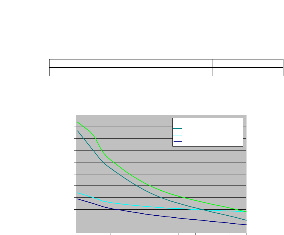
RF300 system planning
4.4 Dependence of the volume of data on the transponder speed with ISO tags
SIMATIC RF300
60 System Manual, 01/2009, A5E01642529-03
4.4.5 MDS D324 with RF310R and RF380R
The following table is used to calculate the curves.
The indicated speeds are applicable for operation without presence check.
RF310R RF380R
Operating distance (Sa) 20 mm 40 mm
MDS D324: Display of speed relative to data volume (read/write)
%\WH
YPV
5HDG5)5
5HDG5)5
:ULWH5)5
:ULWH5)5
0,00
0,20
0,40
0,60
0,80
1,00
1,20
1,40
1,60
1,80
2,00
Figure 4-18 MDS D324 with RF310R and RF380R
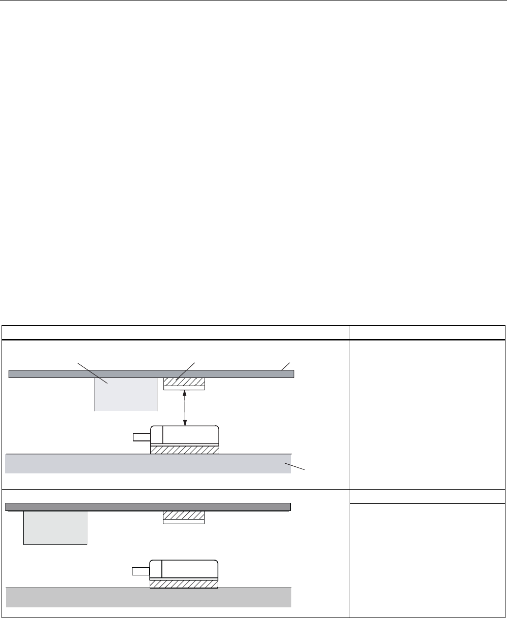
RF300 system planning
4.5 Installation guidelines
SIMATIC RF300
System Manual, 01/2009, A5E01642529-03 61
4.5 Installation guidelines
4.5.1 Overview
The transponder and reader complete with their antennas are inductive devices. Any type of
metal, in particular iron and ferromagnetic materials, in the vicinity of these devices will affect
their operation. Some points need to be considered during planning and installation if the
values described in the "Field data" section are to retain their validity:
● Minimum spacing between two readers or their antennas
● Minimum distance between two adjacent data memories
● Metal-free area for flush-mounting of readers or their antennas and transponders in metal
● Mounting of multiple readers or their antennas on metal frames or racks
The following sections describe the impact on the operation of the identification system when
mounted in the vicinity of metal.
4.5.2 Reduction of interference due to metal
Interference due to metal rack Problem
6KHHW0HWDOUDFN
6D
1RQPHWDOOLFVSDFHU
0HWDO
7UDQVSRQGHU
5HDGHUV
A metal rack is located above the
transmission window of the reader.
This affects the entire field. In
particular, the transmission window
between reader and transponder is
reduced.
Remedy:
7UDQVSRQGHU
5HDGHU
The transmission window is no
longer affected if the transponder is
mounted differently.
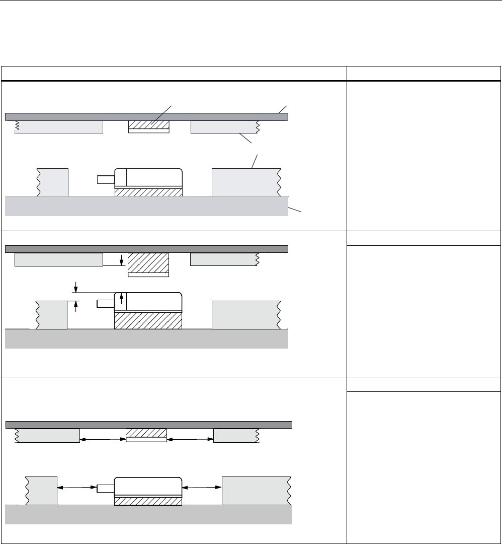
RF300 system planning
4.5 Installation guidelines
SIMATIC RF300
62 System Manual, 01/2009, A5E01642529-03
Flush-mounting
Flush-mounting of transponders and readers Problem
1RQPHWDOOLFVSDFHU 6KHHW
0HWDO
0HWDO
5HDGHUV
Flush-mounting of transponders and
readers is possible in principle.
However, the size of the
transmission window is significantly
reduced. The following measures
can be used to counteract the
reduction of the window:
Remedy:
PP [!PP
5HDGHU
Enlargement of the non-metallic
spacer below the transponder
and/or reader.
The transponder and/or reader are
10 to 20 mm higher than the metal
surround.
(The value x ≥ 100 mm is valid, e.g.
for RF310R. It indicates that, for a
distance x ≥ 100 mm, the reader
can no longer be significantly
affected by metal.)
Remedy:
DD
E
E5HDGHU
Increase the non-metallic distance
a, b.
The following rule of thumb can be
used:
• Increase a, b by a factor of 2 to 3
over the values specified for
metal-free areas
• Increasing a, b has a greater
effect for readers or
transponders with a large limit
distance than for readers or
transponders with a small limit
distance.
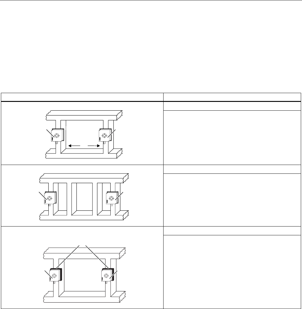
RF300 system planning
4.5 Installation guidelines
SIMATIC RF300
System Manual, 01/2009, A5E01642529-03 63
Mounting of several readers on metal frames or racks
Any reader mounted on metal couples part of the field to the metal frame. There is normally
no interaction as long as the minimum distance D and metal-free areas a, b are maintained.
However, interaction may take place if an iron frame is positioned unfavorably. Longer data
transfer times or sporadic error messages at the communication module are the result.
Mounting of several readers on metal racks Problem: Interaction between readers
Remedy
'
5HDGHU 5HDGHU
Increase the distance D between the two readers.
Remedy
5HDGHU 5HDGHU
Introduce one or more iron struts in order to short-
circuit the stray fields.
Remedy
1RQPHWDOOLF
VSDFHU
5HDGHU 5HDGHU
Insert a non-metallic spacer of 20 to 40 millimeter
thickness between the reader and the iron frame. This
will significantly reduce the induction of stray fields on
the rack:

RF300 system planning
4.5 Installation guidelines
SIMATIC RF300
64 System Manual, 01/2009, A5E01642529-03
4.5.3 Effects of metal on different transponders and readers
Mounting different transponders and readers on metal or flush-mounting
Certain conditions have to be observed when mounting the transponders and readers on
metal or flush-mounting. For more information, please refer to the descriptions of the
individual transponders and readers in the relevant section.
4.5.4 Impact on the transmission window by metal
In general, the following points should be considered when mounting RFID components:
● Direct mounting on metal is allowed only in the case of specially approved transponders.
● Flush-mounting of the components in metal reduces the field data; a test is
recommended in critical applications.
● When working inside the transmission window, it should be ensured that no metal rail (or
similar part) intersects the transmission field.
The metal rail would affect the field data.
The impact of metal on the field data (Sg, Sa, L, B) is shown in tabular format in this section.
The values in the table describe the reduction of the field data in % with reference to non-
metal (100% means no impact).
Reader RF310R:RF300 mode
Table 4- 18 Reduction of field data by metal (in %): Transponder and RF310R
RF310R reader
Transponder
Without metal
On metal Flush-mounted
In metal
(20 mm all
around)
Without metal 100 95 80
On metal; distance 20 mm 100 80 70
RF320T
Flush-mounted in metal; distance
all-round 20 mm
80 70 60
Without metal 100 95 80
On metal 80 80 80
RF340T
Flush-mounted in metal;
distance all-round 20 mm
70 70 70
Without metal 100 95 85
On metal 70 65 65
RF350T
Flush-mounted in metal;
distance all-round 20 mm
60 60 60
Without metal 100 95 85
On metal; distance 20 mm 100 95 75
RF360T
Flush-mounted in metal;
distance all-round 20 mm
60 60 60

RF300 system planning
4.5 Installation guidelines
SIMATIC RF300
System Manual, 01/2009, A5E01642529-03 65
RF310R reader: ISO mode
Table 4- 19 Reduction of field data by metal (in %): Transponder and RF380R (ISO mode)
RF310R reader (ISO mode)
Transponder
Without metal
On metal Flush-mounted
In metal
(20 mm all
around)
Without metal 100 95 80
On metal; distance 20 mm 77 70 67
MDS D100
Flush-mounted in metal; distance
all-round 20 mm
58 55 52
Without metal 100 98 82
On metal 93 94 87
MDS D124
Flush-mounted in metal;
distance all-round 20 mm
82 76 60
Without metal 100 92 83
On metal; distance 20 mm 78 77 74
MDS D160
Flush-mounted in metal;
distance all-round 20 mm
70 63 60
Without metal 100 95 76
On metal 83 81 78
MDS D324
Flush-mounted in metal;
distance all-round 20 mm
79 76 72

RF300 system planning
4.5 Installation guidelines
SIMATIC RF300
66 System Manual, 01/2009, A5E01642529-03
RF340R reader
Table 4- 20 Reduction of field data by metal (in %): Transponder and RF340R
RF340R reader
Transponder
Without metal
On metal Flush-mounted
In metal
(20 mm all
around)
Without metal 100 95 80
On metal; distance 20 mm 100 90 75
RF320T
Flush-mounted in metal; distance
all-round 20 mm
80 70 60
Without metal 100 95 85
On metal 80 80 70
RF340T
Flush-mounted in metal;
distance all-round 20 mm
70 70 70
Without metal 100 95 80
On metal 70 65 65
RF350T
Flush-mounted in metal;
distance all-round 20 mm
60 60 60
Without metal 100 95 85
On metal; distance 20 mm 90 90 75
RF360T
Flush-mounted in metal;
distance all-round 20 mm
70 60 60
Without metal 100 98 96
On metal 100 97 94
RF370T
Flush-mounted in metal;
distance all-round 20 mm
90 88 86
Without metal 100 86 76
(all-round
40 mm)
On metal 100 86 76
(all-round
40 mm)
RF380T
Flush-mounted in metal; distance
all-round 40 mm
83 71 55
(all-round
40 mm)

RF300 system planning
4.5 Installation guidelines
SIMATIC RF300
System Manual, 01/2009, A5E01642529-03 67
RF350R reader with ANT 1
Table 4- 21 Reduction of field data by metal (in %): Transponder and RF350R with ANT 1
RF350R reader
Transponder
Without metal
On metal Flush-mounted
In metal
(20 mm all
around)
Without metal 100 95 80
On metal; distance 20 mm 100 90 75
RF320T
Flush-mounted in metal; distance
all-round 20 mm
80 70 60
Without metal 100 95 85
On metal 80 80 70
RF340T
Flush-mounted in metal;
distance all-round 20 mm
70 70 70
Without metal 100 95 80
On metal 70 65 65
RF350T
Flush-mounted in metal;
distance all-round 20 mm
60 60 60
Without metal 100 95 85
On metal; distance 20 mm 90 90 75
RF360T
Flush-mounted in metal;
distance all-round 20 mm
70 60 60
Without metal 100 86 73
On metal 100 83 69
RF370T
Flush-mounted in metal;
distance all-round 20 mm
90 74 61
Without metal 100 83 73
(all-round
40 mm)
On metal 100 83 73
(all-round
40 mm)
RF380T
Flush-mounted in metal; distance
all-round 40 mm
80 68 53
(all-round
40 mm)

RF300 system planning
4.5 Installation guidelines
SIMATIC RF300
68 System Manual, 01/2009, A5E01642529-03
RF350R reader with ANT 18
Table 4- 22 Reduction of field data by metal (in %): Transponder and RF350R with ANT 18
Mounting the antenna
Transponder
Without metal Flush-mounted
In metal
(10 mm all-round;
10 mm deep)
Without metal 100 100
On metal; distance 20 mm 100 100
RF320T
Flush-mounted in metal; distance
all-round 20 mm
80 80
Without metal 100 100
On metal 80 80
RF340T
Flush-mounted in metal;
distance all-round 20 mm
70 70
Without metal
On metal
RF350T
Flush-mounted in metal;
distance all-round 20 mm
combination not permitted
Without metal
On metal; distance 20 mm
RF360T
Flush-mounted in metal;
distance all-round 20 mm
combination not permitted

RF300 system planning
4.5 Installation guidelines
SIMATIC RF300
System Manual, 01/2009, A5E01642529-03 69
RF350R reader with ANT 30
Table 4- 23 Reduction of field data by metal (in %): Transponder and RF350R with ANT 30
Mounting the antenna
Transponder
Without metal
Flush-mounted
In metal
(20 mm all-round;
20 mm deep)
Without metal 100 80
On metal; distance 20 mm 100 80
RF320T
Flush-mounted in metal; distance
all-round 20 mm
100 80
Without metal 100 80
On metal 80 65
RF340T
Flush-mounted in metal;
distance all-round 20 mm
70 60
Without metal 100 80
On metal 70 60
RF350T
Flush-mounted in metal;
distance all-round 20 mm
65 55
Without metal
On metal; distance 20 mm
RF360T
Flush-mounted in metal;
distance all-round 20 mm
combination not permitted

RF300 system planning
4.5 Installation guidelines
SIMATIC RF300
70 System Manual, 01/2009, A5E01642529-03
Reader RF380R-RF300 mode
Table 4- 24 Reduction of field data by metal (in %): Transponder and RF380R (RF300 mode)
Reader RF380R (RF300 mode)
Transponder
Without metal
On metal Flush-mounted
In metal
(20 mm all
around)
Without metal 100 95 90
On metal; distance 20 mm 85 75 70
RF320T
Flush-mounted in metal; distance
all-round 20 mm
60 55 50
Without metal 100 90 80
On metal 70 65 60
RF340T
Flush-mounted in metal;
distance all-round 20 mm
63 60 55
Without metal 100 85 80
On metal 70 65 60
RF350T
Flush-mounted in metal;
distance all-round 20 mm
55 50 45
Without metal 100 95 85
On metal; distance 20 mm 75 70 65
RF360T
Flush-mounted in metal;
distance all-round 20 mm
60 55 50
Without metal 100 95 85
On metal 90 85 80
RF370T
Flush-mounted in metal;
distance all-round 20 mm
65 63 60
Without metal 100 95 85
On metal 95 90 80
RF380T
Flush-mounted in metal; distance
all-round 40 mm
65 60 58

RF300 system planning
4.5 Installation guidelines
SIMATIC RF300
System Manual, 01/2009, A5E01642529-03 71
RF380R reader: ISO mode
Table 4- 25 Reduction of field data by metal (in %): Transponder and RF380R (ISO mode)
Reader RF380R (ISO mode)
Transponder
Without metal
On metal Flush-mounted
In metal
(20 mm all
around)
Without metal 100 95 80
On metal; distance 20 mm 65 62 58
MDS D100
Flush-mounted in metal; distance
all-round 20 mm
58 53 48
Without metal 100 98 92
On metal 95 92 87
MDS D124
Flush-mounted in metal;
distance all-round 20 mm
70 65 50
Without metal 100 92 75 MDS D139
On metal, distance 30 mm 93 88 72
Without metal 100 95 90
On metal; distance 20 mm 87 85 80
MDS D160
Flush-mounted in metal;
distance all-round 20 mm
73 65 60
Without metal 100 95 85
On metal 85 83 80
MDS D324
Flush-mounted in metal;
distance all-round 20 mm
70 65 60

RF300 system planning
4.6 Chemical resistance of the transponders
SIMATIC RF300
72 System Manual, 01/2009, A5E01642529-03
4.6 Chemical resistance of the transponders
The following table provides an overview of the chemical resistance of the data memories
made of glass-fiber-reinforced epoxy resin. It must be emphasized that the plastic enclosure
is extremely resistant to chemicals in automobiles (e.g.: oil, grease, diesel fuel, gasoline)
which are not listed separately.
Transponders RF320T, RF360T
Transponder RF 320T is resistant to the substances specified in the following table.
Concentration 20 °C 40 °C 60 °C
Acetic acid 100 % ○○
Allylchloride ○○○○
Ammonia gas ○○○○
Ammonia liquid, water-free ᅳ
Ammonium hydroxide 10 % ○○○○
Benzenesulphonic acid ○○○○
Benzoate (Na–, Ca.a.) ○○○○
Benzoic acid ○○○○
Benzole ○○○○
Benzyl chloride ᅳ
Borax ○○○○
Boric acid ○○○○
Brine ᅳ
Bromide (K–, Na.a.) ○○○○
Bromine water ᅳ
Bromine, gas, dry ᅳ
Bromine, liquid ᅳ
Bromoform 100 % ○○○○
Butadiene (1,3–) ○○○○
Butane gas ○○○○
Butanol ᅳ
Butyric acid 100 % ○○
Carbon disulfide 100 % ᅳ
Carbonate (ammonium,
Na.a.)
○○○○
Chloride (ammonium, Na.a.) ○○○○
Chlorine water (saturated
solution)
○○
Chlorine, gas, dry 100 % ᅳ
Chlorine, liquid ᅳ
Chlorobenzene ○○○○
Chloroform ᅳ
Chlorophyl ○○○○
Chlorosulphonic acid 100 % ᅳ
Chromate (K–, Na.a.) Up to 50 % ○○○○

RF300 system planning
4.6 Chemical resistance of the transponders
SIMATIC RF300
System Manual, 01/2009, A5E01642529-03 73
Concentration 20 °C 40 °C 60 °C
Chromic acid Up to 30 % ᅳ
Chromosulphuric acid ᅳ
Citric acid ○○○○
Cresol Up to 90 % ᅳ
Cyanamide ○○○○
Cyanide (K–, Na.a.) ○○○○
Developer ○○○○
Dextrin, w. ○○○○
Diethyl ether ○○○○
Diethylene glycol ○○○○
Dimethyl ether ○○○○
Dioxane ᅳ
Ethanol ○○○○ ○○○○
Ethyl acrylate ○○○○
Ethyl glycol ○○○○
Fixer ○○○○
Fluoride (ammonium, K–,
Na.a.)
○○○○
Formaldehyde 50 % ○○○○
Formamide 100 % ○○○○
Formic acid 50 % ○○○○
100 % ○○
Gasoline, aroma-free ○○○○
Gasoline, containing benzol ○○○○
Glucon acid ○○○○
Glycerine ○○○○
Glycol ○○○○
Hydrochloric acid 10 % ᅳ
Hydrofluoric acid Up to 40 % ○○○○
Hydrogen peroxide 30 % ○○○○
Hydroxide (alkaline earth
metal)
○○○○
Hydroxide (ammonium) 10 % ○○○○
Hydroxide (Na–, K–) 40 % ○○○○
Hypochlorite (K–, Na.a.) ○○○○
Iodide (K–, Na.a.) ○○○○
Lactic acid 100 % ○○
Methanol 100 % ○○○○
Methylene chloride ᅳ
Mineral oils ○○○○
Nitrate (ammonium, K.a.) ○○○○
Nitric acid 25 % ᅳ
Nitroglycerine ᅳ
Oxalic acid ○○○○

RF300 system planning
4.6 Chemical resistance of the transponders
SIMATIC RF300
74 System Manual, 01/2009, A5E01642529-03
Concentration 20 °C 40 °C 60 °C
Phenol 1 % ○○○○
Phosphate (ammonium,
Na.a.)
○○○○
Phosphoric acid 50 % ○○○○
85 % ○○○○
Propanol ○○○○
Silicic acid ○○○○
Soap solution ○○○○
Sulfate (ammonium, Na.a.) ○○○○
Sulfite (ammonium, Na.a.) ᅳ
Sulphur dioxide 100 % ○○
Sulphuric acid 40 % ᅳ
Sulphurous acid ○○
Tar, aroma-free ○○○○
Tartaric acid ○○○○
Trichloroethylene ᅳ
Turpentine ○○○○
Uric acid ○○○○
Urine ○○○○
Abbreviations
○○○○ Resistant
○○○ Virtually resistant
○○ Partially resistant
○ Less resistant
ᅳ Not resistant
w. Aqueous solution
k. g. Cold saturated

RF300 system planning
4.6 Chemical resistance of the transponders
SIMATIC RF300
System Manual, 01/2009, A5E01642529-03 75
Transponders RF340T, RF350T, 370T
The following table gives an overview of the chemical composition of the data memories
made from polyamide 12. The plastic housing has a notably high resistance to chemicals
used in automobiles (e.g.: oil, grease, diesel fuel, gasoline) which are not listed separately.
Concentration 20 °C 60 °C
Acetic acid, w. 50 ᅳ ᅳ
Ammonia gas ○○○○ ○○○○
Ammonia, w. conc. ○○○○ ○○○○
10 ○○○○ ○○○○
Battery acid 30 ○○ ᅳ
Benzol ○○○○ ○○○
Bleach solution (12.5% effective chlorine) ○○ ᅳ
Butane, gas, liquid ○○○○ ○○○○
Butyl acetate (acetic acid butyl ester) ○○○○ ○○○○
n(n) ○○○○ ○○○
Calcium chloride, w. ○○○○ ○○○
Calcium nitrate, w. k. g. ○○○○ ○○○
Carbon tetrachloride ○○○○ ○○○○
Chlorine ᅳ ᅳ
Chrome baths, tech. ᅳ ᅳ
Detergent High ○○○○ ○○○○
Ethyl alcohol, w., undenaturated 96 ○○○○ ○○○
50 ○○○○ ○○○○
Formaldehyde, w. 30 ○○○ ᅳ
10 ○○○○ ○○○
Formalin ○○○ ᅳ
Glycerine ○○○○ ○○○○
Hydrochloric acid 10 ○ ᅳ
Hydrogen sulphide Low ○○○○ ○○○○
Iron salts, w. k. g. ○○○○ ○○○○
Isopropanol ○○○○ ○○○
Lactic acid, w. 50 ○○ ᅳ
10 ○○○ ○○
Lysol ○○ ᅳ
Magnesium salts, w. k. g. ○○○○ ○○○○
Mercury ○○○○ ○○○○
Methyl alcohol, w. 50 ○○○○ ○○○○
Nickel salts, w. k. g. ○○○○ ○○○○
Nitric acid 10 ○ ᅳ
Nitrobenzol ○○○ ○○
Phosphoric acid 10 ○ V
Plasticizer ○○○○ ○○○○
Potassium hydroxide, w. 50 ○○○○ ○○○○
Propane ○○○○ ○○○○

RF300 system planning
4.6 Chemical resistance of the transponders
SIMATIC RF300
76 System Manual, 01/2009, A5E01642529-03
Concentration 20 °C 60 °C
Sodium carbonate, w. (soda) k. g. ○○○○ ○○○○
Sodium chloride, w. k. g. ○○○○ ○○○○
Sodium hydroxide ○○○○ ○○○○
Sulphur dioxide Low ○○○○ ○○○○
Sulphuric acid 25 ○○ ᅳ
Toluene ○○○○ ○○○
Abbreviations
○○○○ Resistant
○○○ Virtually resistant
○○ Partially resistant
○ Less resistant
ᅳ Not resistant
w. Aqueous solution
k. g. Cold saturated

RF300 system planning
4.6 Chemical resistance of the transponders
SIMATIC RF300
System Manual, 01/2009, A5E01642529-03 77
Transponder RF380T
The housing of the heat-resistant data storage unit is made of polyphenylene sulfide (PPS).
The chemical resistance of the data storage unit is excellent. No solvent is known that can
dissolve the plastic at temperatures below 200 °C. A reduction in the mechanical properties
has been observed in aqueous solutions of hydrochloric acid (HCl) and nitric acid (HNO3) at
80 °C. The excellent resistance to all fuel types including methanol is a particular
characteristic. The following table provides an overview of the chemicals investigated.
Test conditions
Substance
Time[days] Temperature[°C]
Evaluation
Acetone 180 55 +
Anti-freeze 180 120 +
Brake fluid 40 80 +
Butanon-2 (methyl ethyl
ketone)
180 60 +
Calcium chloride (saturated) 40 80 +
Caustic soda (30%) 40 93 +
Diesel fuel 180 80 +
Diethyl ether 40 23 +
Engine oil 40 80 +
Frigen 113 40 23 +
Hydrochloric acid (10%) 40 80 –
Kerosine 40 60 +
Methanol 180 60 +
n-Butanol (butyl alcohol) 180 80 +
n-butyl acetate 180 80 +
Nitric acid (10%) 40 23 +
Sodium chloride (saturated) 40 80 +
Sodium hydroxide (30%) 180 80 +
Sodium hypochlorite (5%) 30 80 /
180 80 –
Sulphuric acid (10%) 40 23 +
(10%) 40
(30%) 40
Tested fuels: 40 80 +
(FAM-DIN 51 604-A) 180 80 /
Toluene
1, 1, 1-trichloroethane 180 80 +
Xylene
Zinc chloride (saturated) 180 80 /
180 75 +
180 80 +
40 80 +

RF300 system planning
4.6 Chemical resistance of the transponders
SIMATIC RF300
78 System Manual, 01/2009, A5E01642529-03
Test conditions
Assessment:
+ Resistant, weight gain < 3 % or weight loss < 0.5 % and/or reduction in fracture resistance < 15
%
/ Partially resistant, weight gain 3 to 8 % or weight loss 0.5 to 3 % and/or reduction in fracture
resistance 15 to 30 %
– Not resistant, weight gain > 8 % or weight loss > 3 % and/or reduction in fracture resistance
> 30 %

RF300 system planning
4.7 EMC Directives
SIMATIC RF300
System Manual, 01/2009, A5E01642529-03 79
4.7 EMC Directives
4.7.1 Overview
These EMC Guidelines answer the following questions:
● Why are EMC guidelines necessary?
● What types of external interference have an impact on the system?
● How can interference be prevented?
● How can interference be eliminated?
● Which standards relate to EMC?
● Examples of interference-free plant design
The description is intended for "qualified personnel":
● Project engineers and planners who plan system configurations with RFID modules and
have to observe the necessary guidelines.
● Fitters and service engineers who install the connecting cables in accordance with this
description or who rectify defects in this area in the event of interference.
NOTICE
Failure to observe notices drawn to the reader's attention can result in dangerous
conditions in the plant or the destruction of individual components or the entire plant.

RF300 system planning
4.7 EMC Directives
SIMATIC RF300
80 System Manual, 01/2009, A5E01642529-03
4.7.2 What does EMC mean?
The increasing use of electrical and electronic devices is accompanied by:
● Higher component density
● More switched power electronics
● Increasing switching rates
● Lower power consumption of components due to steeper switching edges
The higher the degree of automation, the greater the risk of interaction between devices.
Electromagnetic compatibility (EMC) is the ability of an electrical or electronic device to
operate satisfactorily in an electromagnetic environment without affecting or interfering with
the environment over and above certain limits.
EMC can be broken down into three different areas:
● Intrinsic immunity to interference:
immunity to internal electrical disturbance
● Immunity to external interference:
immunity to external electromagnetic disturbance
● Degree of interference emission:
emission of interference and its effect on the electrical environment
All three areas are considered when testing an electrical device.
The RFID modules are tested for conformity with the limit values required by the CE and
RTTE guidelines. Since the RFID modules are merely components of an overall system, and
sources of interference can arise as a result of combining different components, certain
guidelines have to be followed when setting up a plant.
EMC measures usually consist of a complete package of measures, all of which need to be
implemented in order to ensure that the plant is immune to interference.
Note
The plant manufacturer is responsible for the observance of the EMC guidelines; the plant
operator is responsible for radio interference suppression in the overall plant.
All measures taken when setting up the plant prevent expensive retrospective modifications
and interference suppression measures.
The plant operator must comply with the locally applicable laws and regulations. They are
not covered in this document.

RF300 system planning
4.7 EMC Directives
SIMATIC RF300
System Manual, 01/2009, A5E01642529-03 81
4.7.3 Basic rules
It is often sufficient to follow a few elementary rules in order to ensure electromagnetic
compatiblity (EMC).
The following rules must be observed:
Shielding by enclosure
● Protect the device against external interference by installing it in a cabinet or housing.
The housing or enclosure must be connected to the chassis ground.
● Use metal plates to shield against electromagnetic fields generated by inductances.
● Use metal connector housings to shield data conductors.
Wide-area ground connection
● Bond all passive metal parts to chassis ground, ensuring large-area and low-HF-
impedance contact.
● Establish a large-area connection between the passive metal parts and the central
grounding point.
● Don't forget to include the shielding bus in the chassis ground system. That means the
actual shielding busbars must be connected to ground by large-area contact.
● Aluminium parts are not suitable for ground connections.
Plan the cable installation
● Break the cabling down into cable groups and install these separately.
● Always route power cables, signal cables and HF cables through separated ducts or in
separate bundles.
● Feed the cabling into the cabinet from one side only and, if possible, on one level only.
● Route the signal cables as close as possible to chassis surfaces.
● Twist the feed and return conductors of separately installed cables.
● Routing HF cables:
avoid parallel routing of HF cables.
● Do not route cables through the antenna field.
Shielding for the cables
● Shield the data cables and connect the shield at both ends.
● Shield the analog cables and connect the shield at one end, e.g. on the drive unit.
● Always apply large-area connections between the cable shields and the shielding bus at
the cabinet inlet and make the contact with clamps.
● Feed the connected shield through to the module without interruption.
● Use braided shields, not foil shields.
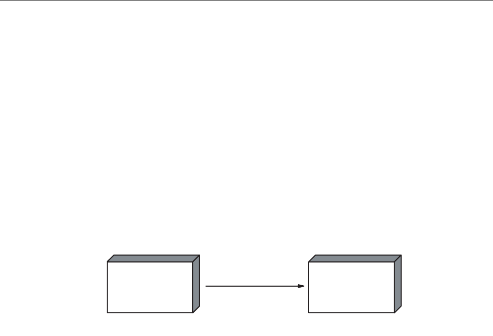
RF300 system planning
4.7 EMC Directives
SIMATIC RF300
82 System Manual, 01/2009, A5E01642529-03
Line and signal filter
● Use only line filters with metal housings
● Connect the filter housing to the cabinet chassis using a large-area low-HF-impedance
connection.
● Never fix the filter housing to a painted surface.
● Fix the filter at the control cabinet inlet or in the direction of the source.
4.7.4 Propagation of electromagnetic interference
Three components have to be present for interference to occur in a system:
● Interference source
● Coupling path
● Interference sink
HJFRQQHFWLQJFDEOH
,QWHUIHUHQFHVRXUFH
GHYLFHHPLWWLQJ
LQWHUIHUHQFH
&RXSOLQJSDWK
HJGULYHXQLW HJUHDGHU
,QWHUIHUHQFHVLQN
GHYLFHDIIHFWHGE\
LQWHUIHUHQFH
Figure 4-19 Propagation of interference
If one of the components is missing, e.g. the coupling path between the interference source
and the interference sink, the interference sink is unaffected, even if the interference source
is transmitting a high level of noise.
The EMC measures are applied to all three components, in order to prevent malfunctions
due to interference. When setting up a plant, the manufacturer must take all possible
measures in order to prevent the occurrence of interference sources:
● Only devices fulfilling limit class A of VDE 0871 may be used in a plant.
● Interference suppression measures must be introduced on all interference-emitting
devices. This includes all coils and windings.
● The design of the system must be such that mutual interference between individual
components is precluded or kept as small as possible.
Information and tips for plant design are given in the following sections.

RF300 system planning
4.7 EMC Directives
SIMATIC RF300
System Manual, 01/2009, A5E01642529-03 83
Interference sources
In order to achieve a high level of electromagnetic compatibility and thus a very low level of
disturbance in a plant, it is necessary to recognize the most frequent interference sources.
These must then be eliminated by appropriate measures.
Table 4- 26 Interference sources: origin and effect
Interference source Interference results from Effect on the interference sink
Contacts System disturbances Contactors,
electronic valves Coils Magnetic field
Collector Electrical field Electrical motor
Winding Magnetic field
Contacts Electrical field Electric welding device
Transformer Magnetic field, system disturbance,
transient currents
Power supply unit, switched-
mode
Circuit Electrical and magnetic field, system
disturbance
High-frequency appliances Circuit Electromagnetic field
Transmitter
(e.g. service radio)
Antenna Electromagnetic field
Ground or reference potential
difference
Voltage difference Transient currents
Operator Static charge Electrical discharge currents, electrical
field
Power cable Current flow Electrical and magnetic field, system
disturbance
High-voltage cable Voltage difference Electrical field
What interference can affect RFID?
Interference source Cause Remedy
Switched-mode power supply Interference emitted from the
current infeed
Replace the power supply
Cable is inadequately
shielded
Better cable shielding Interference injected through
the cables connected in
series The reader is not connected
to ground.
Ground the reader
HF interference over the
antennas
caused by another reader • Position the antennas further
apart.
• Erect suitable damping materials
between the antennas.
• Reduce the power of the readers.
Please follow the instructions in the
section
Installation guidelines/reducing
the effects of metal
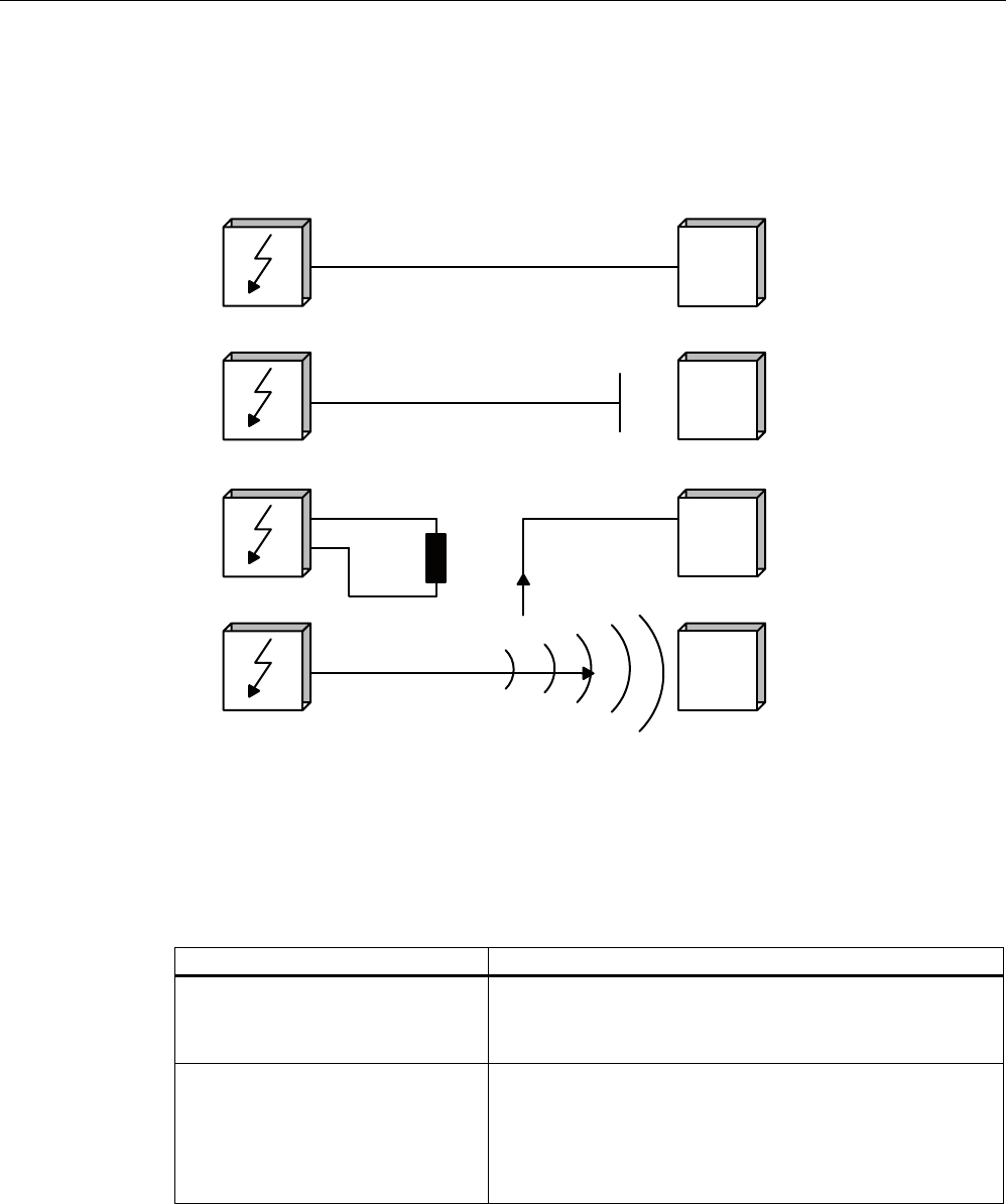
RF300 system planning
4.7 EMC Directives
SIMATIC RF300
84 System Manual, 01/2009, A5E01642529-03
Coupling paths
A coupling path has to be present before the disturbance emitted by the interference source
can affect the system. There are four ways in which interference can be coupled in:
,
1
7
(
5
)
(
5
(
1
&
(
6
,
1
.
*DOYDQLFFRXSOLQJSDWK
&DSDFLWLYHFRXSOLQJSDWK
,QGXFWLYHFRXSOLQJSDWK
5DGLDWLRQFRXSOLQJ
5),'
5HDGHU
5),'
5HDGHU
5),'
5HDGHU
5),'
5HDGHU
,
1
7
(
5
)
(
5
(
1
&
(
6
2
8
5
&
(
Figure 4-20 Ways in which interference can be coupled in
When RFID modules are used, different components in the overall system can act as a
coupling path:
Table 4- 27 Causes of coupling paths
Coupling path Invoked by
Conductors and cables • Incorrect or inappropriate installation
• Missing or incorrectly connected shield
• Inappropriate physical arrangement of cables
Control cabinet or housing • Missing or incorrectly wired equalizing conductor
• Missing or incorrect earthing
• Inappropriate physical arrangement
• Components not mounted securely
• Unfavorable cabinet configuration
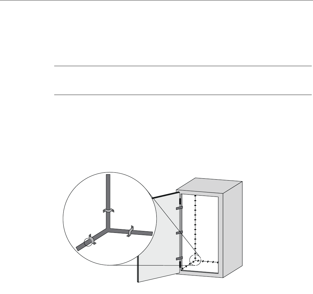
RF300 system planning
4.7 EMC Directives
SIMATIC RF300
System Manual, 01/2009, A5E01642529-03 85
4.7.5 Cabinet configuration
The influence of the user in the configuration of an electromagnetically compatible plant
encompasses cabinet configuration, cable installation, ground connections and correct
shielding of cables.
Note
For information about electromagnetically compatible cabinet configuration, please consult
the installation guidelines for SIMATIC PLCs.
Shielding by enclosure
Magnetic and electrical fields and electromagnetic waves can be kept away from the
interference sink by using a metal enclosure. The easier the induced interference current can
flow, the greater the intrinsic weakening of the interference field. All enclosures and metal
panels in the cabinet should therefore be connected in a manner allowing good
conductance.
Figure 4-21 Shielding by enclosure
If the control cabinet panels are insulated from each other, a high-frequency-conducting
connection can be established using ribbon cables and high-frequency terminals or HF
conducting paste. The larger the area of the connection, the greater the high-frequency
conductivity. This is not possible using single-wire connections.
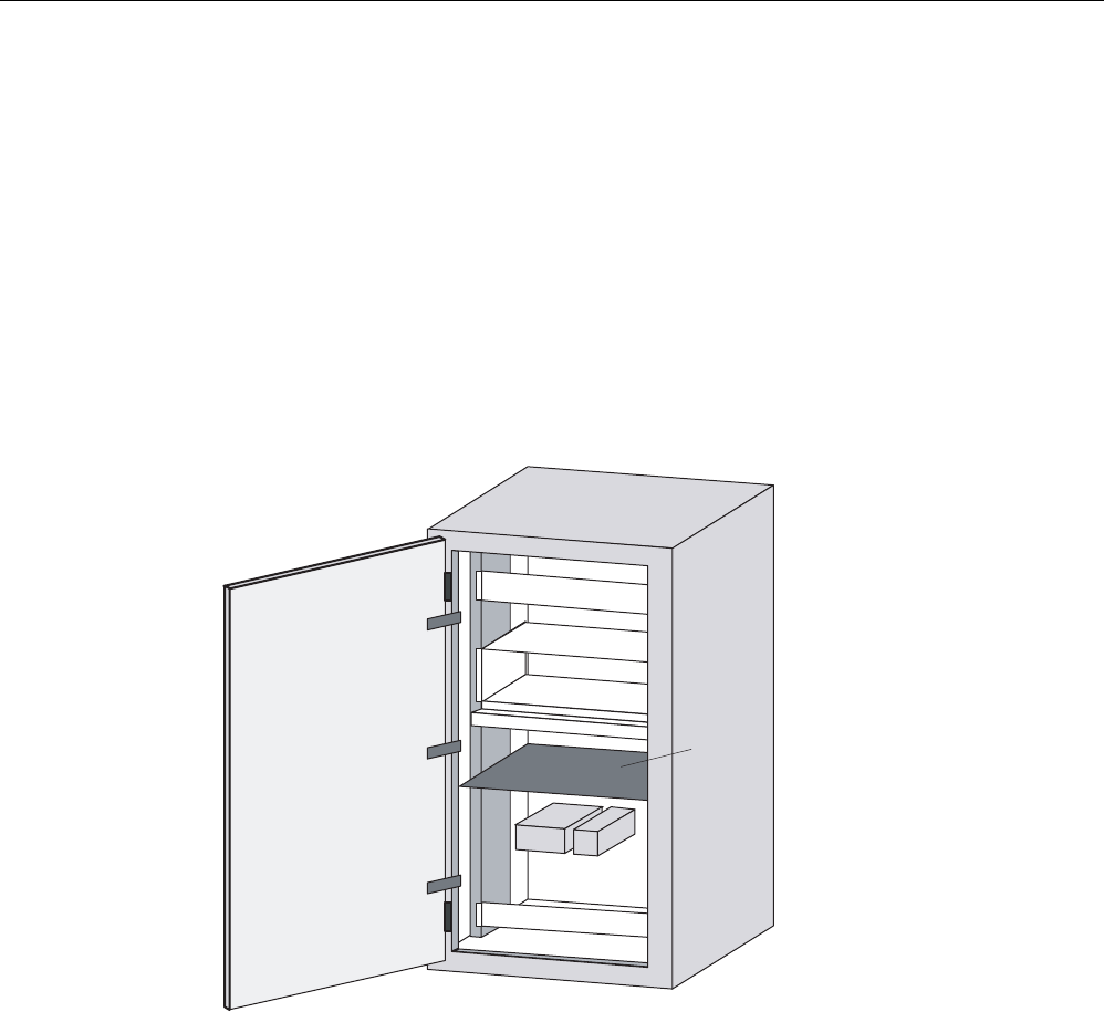
RF300 system planning
4.7 EMC Directives
SIMATIC RF300
86 System Manual, 01/2009, A5E01642529-03
Prevention of interference by optimum configuration
Good interference suppression can be achieved by installing SIMATIC PLCs on conducting
mounting plates (unpainted). When setting up the control cabinet, interference can be
prevented easily by observing certain guidelines. Power components (transformers, drive
units, load power supply units) should be arranged separately from the control components
(relay control unit, SIMATIC S7).
As a rule:
● The effect of the interference decreases as the distance between the interference source
and interference sink increases.
● The interference can be further decreased by installing grounded shielding plates.
● The load connections and power cables should be installed separately from the signal
cables with a minimum clearance of 10 cm.
3RZHUVXSSO\
&&(8
'ULYH
6KLHOG
SODWH
Figure 4-22 Prevention of interference by optimum configuration
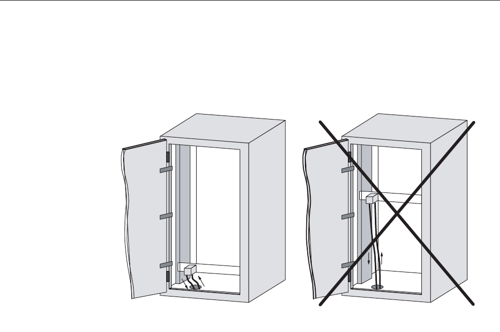
RF300 system planning
4.7 EMC Directives
SIMATIC RF300
System Manual, 01/2009, A5E01642529-03 87
Filtering of the supply voltage
External interference from the mains can be prevented by installing line filters. Correct
installation is extremely important, in addition to appropriate dimensioning. It is essential that
the line filter is mounted directly at the cabinet inlet. As a result, interference is filtered
promptly at the inlet, and is not conducted through the cabinet.
/LQHILOWHU
,V
&RUUHFW
/LQHILOWHU
,QFRUUHFW
,F LQWHUIHUHQFHFXUUHQW
,V
Figure 4-23 Filtering of the supply voltage

RF300 system planning
4.7 EMC Directives
SIMATIC RF300
88 System Manual, 01/2009, A5E01642529-03
4.7.6 Prevention of interference sources
A high level of immunity to interference can be achieved by avoiding interference sources.
All switched inductances are frequent sources of interference in plants.
Suppression of inductance
Relays, contactors, etc. generate interference voltages and must therefore be suppressed
using one of the circuits below.
Even with small relays, interference voltages of up to 800 V occur on 24 V coils, and
interference voltages of several kV occur on 230 V coils when the coil is switched. The use
of freewheeling diodes or RC circuits prevents interference voltages and thus stray
interference on conductors installed parallel to the coil conductor.
9DOYHV
%UDNHV
5HOD\FRLOV
&RQWDFWRUV
Figure 4-24 Suppression of inductance
Note
All coils in the cabinet should be suppressed. The valves and motor brakes are frequently
forgotten. Fluorescent lamps in the control cabinet should be tested in particular.
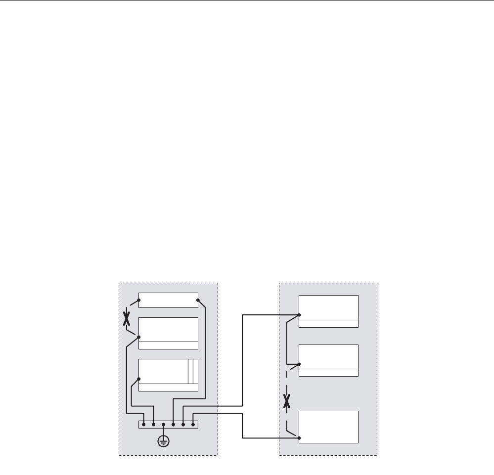
RF300 system planning
4.7 EMC Directives
SIMATIC RF300
System Manual, 01/2009, A5E01642529-03 89
4.7.7 Equipotential bonding
Potential differences between different parts of a plant can arise due to the different design
of the plant components and different voltage levels. If the plant components are connected
across signal cables, transient currents flow across the signal cables. These transient
currents can corrupt the signals.
Proper equipotential bonding is thus essential.
● The equipotential bonding conductor must have a sufficiently large cross section (at least
10 mm2).
● The distance between the signal cable and the associated equipotential bonding
conductor must be as small as possible (antenna effect).
● A fine-strand conductor must be used (better high-frequency conductivity).
● When connecting the equipotential bonding conductors to the centralized equipotential
bonding strip (EBS), the power components and non-power components must be
combined.
● The equipotential bonding conductors of the separate modules must lead directly to the
equipotential bonding strip.
&DELQHW &DELQHW
,QFRUUHFW
3RZHUVXSSO\
'ULYH
'HYLFH
3/&
(%6
'HYLFH
'HYLFH
,QFRUUHFW
Figure 4-25 Equipotential bonding (EBS = Equipotential bonding strip)
The better the equipotential bonding in a plant, the smaller the chance of interference due to
fluctuations in potential.
Equipotential bonding should not be confused with protective earthing of a plant. Protective
earthing prevents the occurrence of excessive shock voltages in the event of equipment
faults whereas equipotential bonding prevents the occurrence of differences in potential.
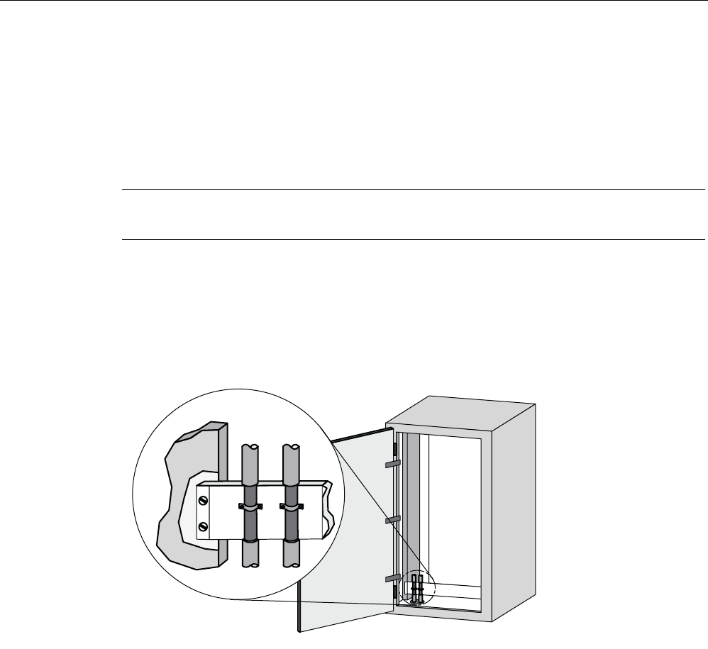
RF300 system planning
4.7 EMC Directives
SIMATIC RF300
90 System Manual, 01/2009, A5E01642529-03
4.7.8 Cable shielding
Signal cables must be shielded in order to prevent coupling of interference.
The best shielding is achieved by installing the cables in steel tubes. However, this is only
necessary if the signal cable is routed through an environment prone to particular
interference. It is usually adequate to use cables with braided shields. In either case,
however, correct connection is vital for effective shielding.
Note
An unconnected or incorrectly connected shield has no shielding effect.
As a rule:
● For analog signal cables, the shield should be connected at one end on the receiver side
● For digital signals, the shield should be connected to the enclosure at both ends
● Since interference signals are frequently within the HF range (> 10 kHz), a large-area HF-
proof shield contact is necessary
Figure 4-26 Cable shielding
The shielding bus should be connected to the control cabinet enclosure in a manner allowing
good conductance (large-area contact) and must be situated as close as possible to the
cable inlet. The cable insulation must be removed and the cable clamped to the shielding
bus (high-frequency clamp) or secured using cable ties. Care should be taken to ensure that
the connection allows good conductance.
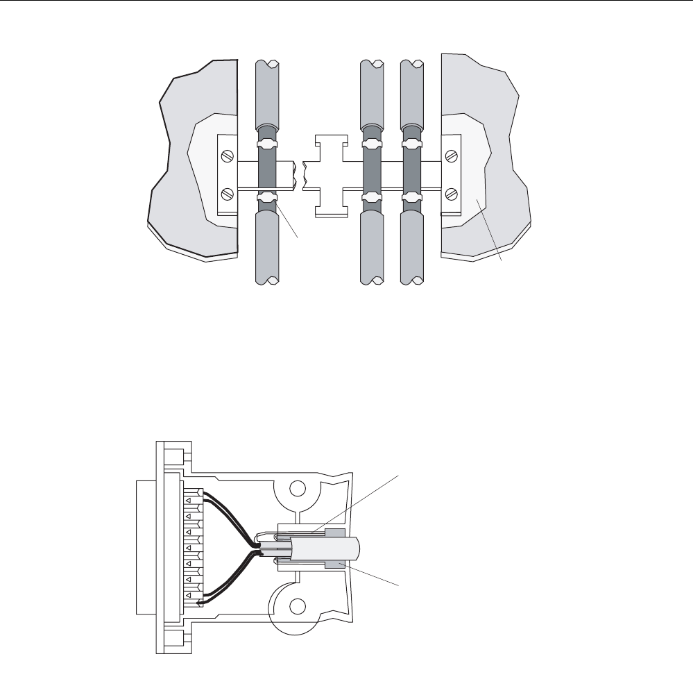
RF300 system planning
4.7 EMC Directives
SIMATIC RF300
System Manual, 01/2009, A5E01642529-03 91
5HPRYHSDLQW
&DEOHWLH
Figure 4-27 Connection of shielding bus
The shielding bus must be connected to the PE busbar.
If shielded cables have to be interrupted, the shield must be continued via the corresponding
connector housing. Only suitable connectors may be used for this purpose.
6KLHOGWXUQHGXSVLGHGRZQ
WKURXJKrDQG
FRQQHFWHGWRFRQQHFWRU
KRXVLQJ
5XEEHUVOHHYH
Figure 4-28 Interruption of shielded cables
If intermediate connectors, which do not have a suitable shield connection, are used, the
shield must be continued by fixing cable clamps at the point of interruption. This ensures a
large-area, HF-conducting contact.

RF300 system planning
4.7 EMC Directives
SIMATIC RF300
92 System Manual, 01/2009, A5E01642529-03

SIMATIC RF300
System Manual, 01/2009, A5E01642529-03 93
Readers 5
Overview
The reader ensures inductive communication with the transponders, and handles the serial
connection to the communication modules or the 8xIQ-Sense module.
Communication between the transponder and reader takes place over inductive alternating
fields.
The transmittable data volume between reader and transponder depends on:
● the speed at which the transponder moves through the transmission window of the
reader.
● the length of the transmission window.
● the RF300 transponder type (FRAM, EEPROM).
● the use of ISO transponders
ISO functionality
With the following readers, you can also use ISO tags:
● SIMATIC RF310R reader (with RS422 interface)
● SIMATIC RF380R reader
The readers must either be parameterized for the RF300 or ISO mode. The parameterization
is done with the aid of the RESET message frame (INIT-Run).
You can find more detailed information on the software parameterization in Product
Information "FB 45 and FC 45 input parameters for RF300 and ISO transponders"
(http://support.automation.siemens.com/WW/view/en/33315697) or the Function Manuals
FB 45 (http://support.automation.siemens.com/WW/view/en/21738808) and
FC 45 (http://support.automation.siemens.com/WW/view/en/21737722) as of the A3 edition.
Note
ISO functionality is only possible with certain reader MLFBs.
Only the SIMATIC RF310R and SIMATIC RF380R readers with the MLFB 6GT2801-xxBxx
are suitable for operating with ISO tags.
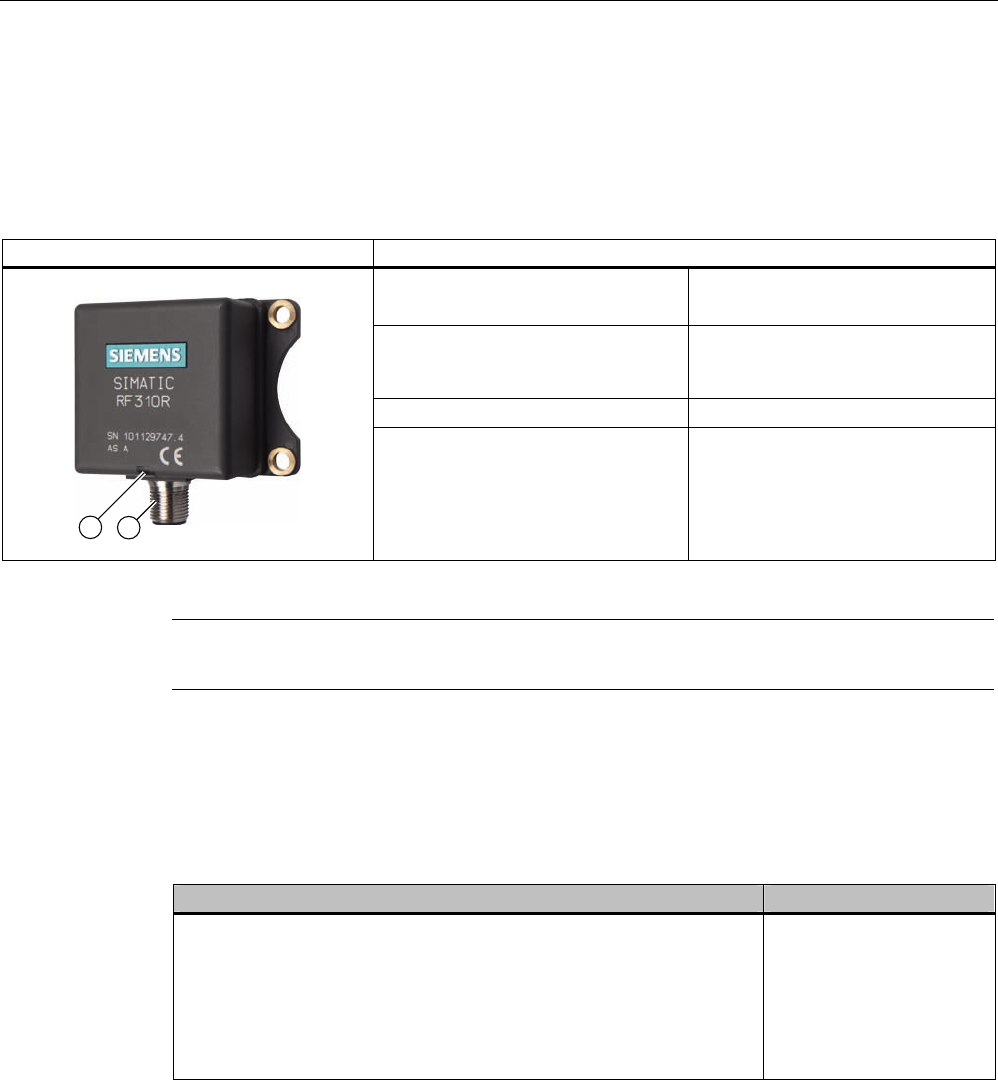
Readers
5.1 SIMATIC RF310R with IQ-Sense interface
SIMATIC RF300
94 System Manual, 01/2009, A5E01642529-03
5.1 SIMATIC RF310R with IQ-Sense interface
5.1.1 Features
RF310R with IQ-Sense Characteristics
Design ① IQ-Sense interface
② Status display
Field of application Identification tasks on small
assembly lines in harsh industrial
environments
Read/write distance to transponder Max. 35 mm
Data transmission rate • Read: approx. 50 bytes/s
• Write: approx. 40 bytes/s
Note
SIMATIC RF310R with IQ-Sense interface is not suitable for combining with ISO tags.
5.1.2 Ordering data of RF310R with IQ-Sense interface
Table 5- 1
RF310R Order number
• With IQ-Sense interface
• IP67
• Operating temperature: -25 °C to +70 °C
• Dimensions: 55 x 75 x 30 (L x W x H, in mm)
• with integrated antenna
• Max. limit distance: 35 mm (depending on transponder)
6GT2801-0AA00
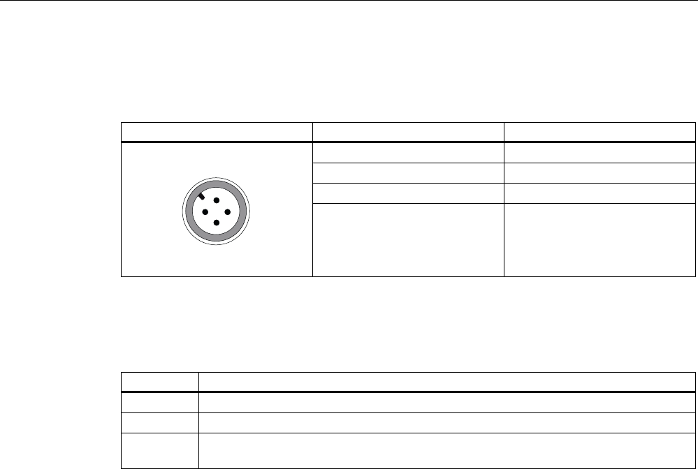
Readers
5.1 SIMATIC RF310R with IQ-Sense interface
SIMATIC RF300
System Manual, 01/2009, A5E01642529-03 95
5.1.3 Pin assignment of RF310R IQ-Sense interface
Table 5- 2 Pin assignment of RF310R with IQ-Sense interface
Pin Pin, device end, 4-pin M12 Assignment
1 IQ-Sense
2 Not assigned
3 IQ-Sense
4 Not connected
5.1.4 Display elements of the RF310R reader with IQ-Sense interface
Color Meaning
Green Operating voltage available
yellow Transponder present
Red Error occurred (see FC35 documentation, Section "Error messages and
troubleshooting", Subsection "Error messages, error_MOBY")
5.1.5 Ensuring reliable data exchange
The "center point" of the transponder must be situated within the transmission window.
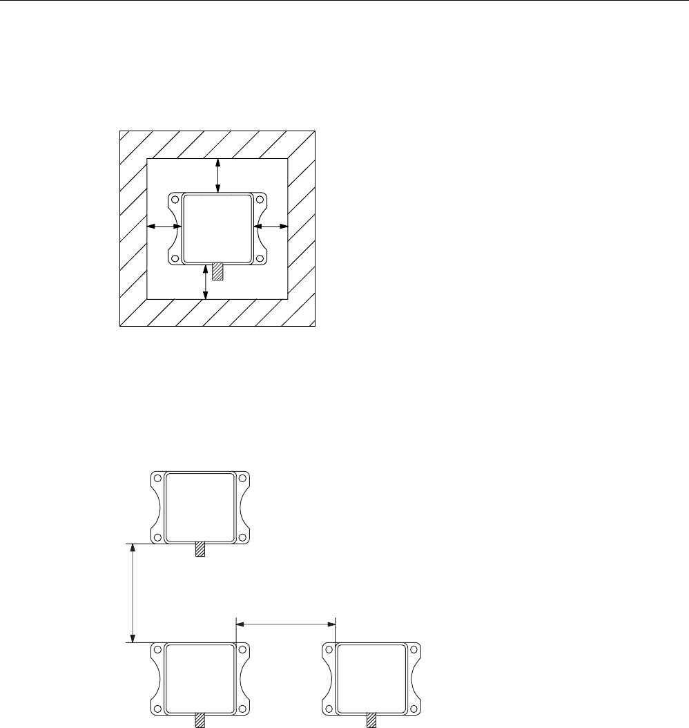
Readers
5.1 SIMATIC RF310R with IQ-Sense interface
SIMATIC RF300
96 System Manual, 01/2009, A5E01642529-03
5.1.6 Metal-free area
The RF310R can be flush-mounted in metal. Please allow for a possible reduction in the field
data values.
D
D
DD
6,0$7,&
5)5
Figure 5-1 Metal-free area for RF310R
To avoid any impact on the field data, the distance a should be ≥ 20 mm.
5.1.7 Minimum distance between RF310R readers
'D
'E
5)5
6,0$7,&
5)5
6,0$7,&
5)5
6,0$7,&
Da ≥ 100 mm
Db ≥ 100 mm
Figure 5-2 Minimum distance between RF310R readers

Readers
5.1 SIMATIC RF310R with IQ-Sense interface
SIMATIC RF300
System Manual, 01/2009, A5E01642529-03 97
5.1.8 Technical data for RF310R reader with IQ-Sense interface
Table 5- 3 Technical specifications for RF310R reader with IQ-Sense interface
Inductive interface to the transponder
Transmission frequency for power/data
13.56 MHz
Interface to SIMATIC S7-300
Required master module
RFID channels (RF310R)
Mixed operation with other profiles
IQ-Sense, 2-wire non-polarized
8-IQ-Sense (6ES7 338-7XF00-0AB0)
max. 2 per master module,
max. 4 Opto-BEROs, 1x SIMATIC RF310R
Cable length reader - communication module Max. 50 m (unshielded cable)
Read/write distances of reader See Chapter Field data of RF300 transponders
(Page 44)
Minimum distance between two RF310R readers ≥ 100 mm
Data transfer rate for read/write device
Reading
Writing
Approx. 50 byte/s
Approx. 40 byte/s
Passing speed
Reading
Writing
Approx. 0.8 m/s (2 bytes)
Approx. 0.8 m/s (2 bytes)
Function Read, write, initialize transponder
Multi-tag No
Power supply via IQ-Sense master module 24 V DC
Display elements 2-color LED (operating voltage,
presence, error)
Plug-in connector M12 (4-pin)
Enclosure
Dimensions (in mm)
Color
Material
55 x 75 x 30 (without M12 enclosure connector)
Anthracite
Plastic PA 12
Fixing 4 x M5 screws
Ambient temperature
during operation
during transport and storage
-25°C to +70°C
-40°C to +85°C
Degree of protection to EN 60529
Shock to EN 60721-3-7 Class 7 M2
Vibration to EN 60721-3-7 Class 7 M2
IP67
50 g
20 g
Weight Approx. 150 g
MTBF (Mean Time Between Failures) in years 153.5
Approvals Radio to R&TTE guidelines EN 300 330,
EN 301 489, CE, FCC, UL/CSA
Current consumption Typ. 40 mA
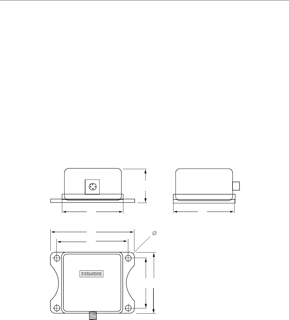
Readers
5.1 SIMATIC RF310R with IQ-Sense interface
SIMATIC RF300
98 System Manual, 01/2009, A5E01642529-03
5.1.9 FCC information
Siemens SIMATIC RF300 with IQ-Sense interface
FCC ID: NXW-RF310R-IQ
This device complies with Part 15 of the FCC Rules. Operation is subject to the following two
conditions:
(1) This device may not cause harmful interference.
(2) This device must accept any interference received, including interference that may cause
undesired operation.
Caution
Any changes or modifications not expressly approved by the party responsible for
compliance could void the user's authority to operate the equipment.
5.1.10 Dimension drawing
6,0$7,&
5)5
Figure 5-3 Dimension drawing for RF310R
Dimensions in mm
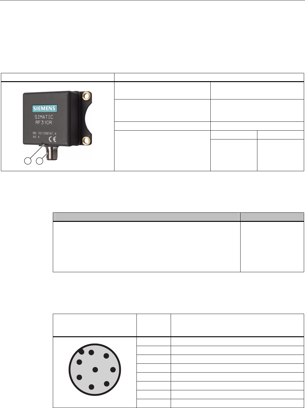
Readers
5.2 SIMATIC RF310R with RS422 interface
SIMATIC RF300
System Manual, 01/2009, A5E01642529-03 99
5.2 SIMATIC RF310R with RS422 interface
5.2.1 Features
RF310R with RS422 Characteristics
Design ① RS422 interface
② Status display
Field of application Identification tasks on small
assembly lines in harsh industrial
environments
Read/write distance to transponder Max. 35 mm
RF300 tags ISO tags
Data transmission rate
Read
write
Approx. 8000
bytes/s
Approx. 8000
bytes/s
Approx. 600
bytes/s
Approx. 400
bytes/s
5.2.2 Ordering data for RF310R with RS422 interface
RF310R Order number
• With RS422 interface (3964R)
• IP67
• Operating temperature: -25 °C to +70 °C
• Dimensions: 55 x 75 x 30 (L x W x H, in mm)
• with integrated antenna
• Max. limit distance: 35 mm (depending on transponder)
6GT2801-1AB10
5.2.3 Pin assignment of RF310R RS422 interface
Pin Pin
Device end
8-pin M12
Assignment
1 + 24 V
2 - Transmit
3 0 V
4 + Transmit
5 + Receive
6 - Receive
7 Free
8 Earth (shield)
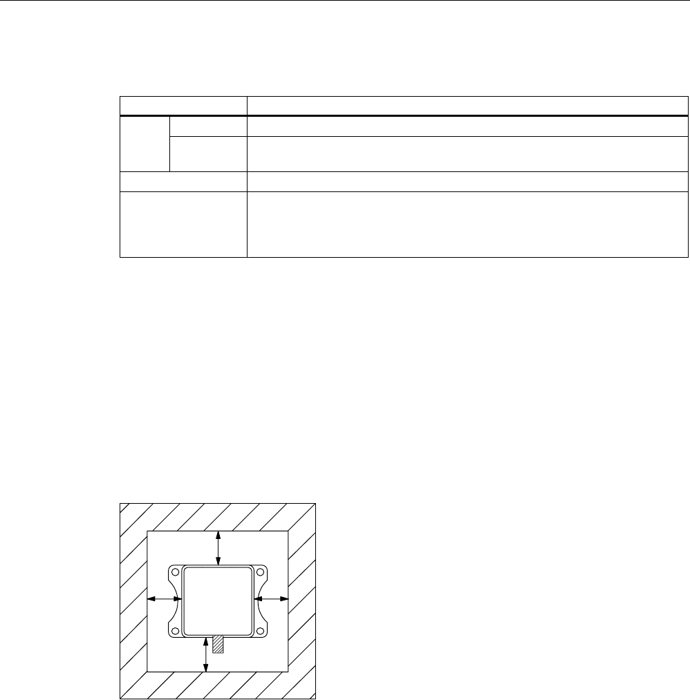
Readers
5.2 SIMATIC RF310R with RS422 interface
SIMATIC RF300
100 System Manual, 01/2009, A5E01642529-03
5.2.4 Display elements of the RF310R reader with RS422 interface
Color Meaning
Flashing Operating voltage present, reader not initialized or antenna switched off Green
Permanentl
y on
Operating voltage present, reader initialized and antenna switched on
Yellow1) Transponder present
Flashing red Error has occurred, the type of flashing corresponds to the error code in the
table in Section "Error codes". The optical error display is only reset if the
corresponding reset parameter ("option_1", see FC45 / FB45 documentation,
Section "Input parameters") is set.
1) Only in the "with presence" mode.
5.2.5 Ensuring reliable data exchange
The "center point" of the transponder must be situated within the transmission window.
5.2.6 Metal-free area
The RF310R can be flush-mounted in metal. Please allow for a possible reduction in the field
data values.
D
D
DD
6,0$7,&
5)5
Figure 5-4 Metal-free area for RF310R
To avoid any impact on the field data, the distance a should be ≥ 20 mm.
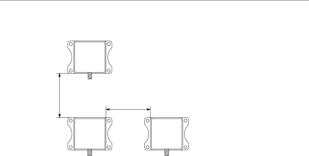
Readers
5.2 SIMATIC RF310R with RS422 interface
SIMATIC RF300
System Manual, 01/2009, A5E01642529-03 101
5.2.7 Minimum distance between RF310R readers
'D
'E
5)5
6,0$7,&
5)5
6,0$7,&
5)5
6,0$7,&
Da ≥ 100 mm
Db ≥ 200 mm
Figure 5-5 Minimum distance between RF310R readers

Readers
5.2 SIMATIC RF310R with RS422 interface
SIMATIC RF300
102 System Manual, 01/2009, A5E01642529-03
5.2.8 Technical specifications of the RF310R reader with RS422 interface
Table 5- 4 Technical specifications of the RF310R reader with RS422 interface
Inductive interface to the transponder
Transmission frequency for power/data
13.56 MHz
Antenna integrated
Interface to the communication module RS422 (3964R protocol)
Baud rate 19200 baud, 57600 baud, 115200 baud
Cable length reader - communication module Data cable length max. 1000 m
(shielded cable)
Read/write distances of reader See Chapter Field data of RF300 transponders
(Page 44)
Minimum distance between two RF310R readers ≥ 100 mm or ≥ 200 mm
RF300 tags
ISO tags Maximum data transmission range, reader -
transponder (tag)
Read
write
Approx. 8000 bytes/s
Approx. 8000 bytes/s
Approx. 600 bytes/s
Approx. 400 bytes/s
Functions Initialize/read/write transponder
Scan status and diagnostics information
Switch antenna on/off
Repeat command
Scan transponder serial numbers
Power supply 24 V DC
Display elements 2-color LED (operating voltage,
presence, error)
Plug-in connector M12 (8-pin)
Enclosure
Dimensions (in mm)
Color
Material
55 x 75 x 30 (without M12 plug connector)
Anthracite
Plastic PA 12
Fixing 4 x M5 screws
Ambient temperature
during operation
during transport and storage
-25 °C to +70 °C
-40 °C to +85 °C
Degree of protection to EN 60529
Shock to EN 60721-3-7 Class 7 M2
Vibration to EN 60721-3-7 Class 7
IP67
50 g
20g
Weight Approx. 170 g
MTBF (Mean Time Between Failures) in years 169.9
Approvals Radio to R&TTE guidelines EN 300 330,
EN 301 489, CE, FCC, UL/CSA
Current consumption Typ. 50 mA

Readers
5.2 SIMATIC RF310R with RS422 interface
SIMATIC RF300
System Manual, 01/2009, A5E01642529-03 103
5.2.9 FCC information
Siemens SIMATIC RF310R with RS422 interface
FCC ID: NXW-RF310R
This device complies with Part 15 of the FCC Rules. Operation is subject to the following two
conditions:
(1) This device may not cause harmful interference.
(2) This device must accept any interference received, including interference that may cause
undesired operation.
Caution
Any changes or modifications not expressly approved by the party responsible for
compliance could void the user's authority to operate the equipment.
5.2.10 Dimension drawing
6,0$7,&
5)5
Figure 5-6 Dimension drawing for RF310R
Dimensions in mm
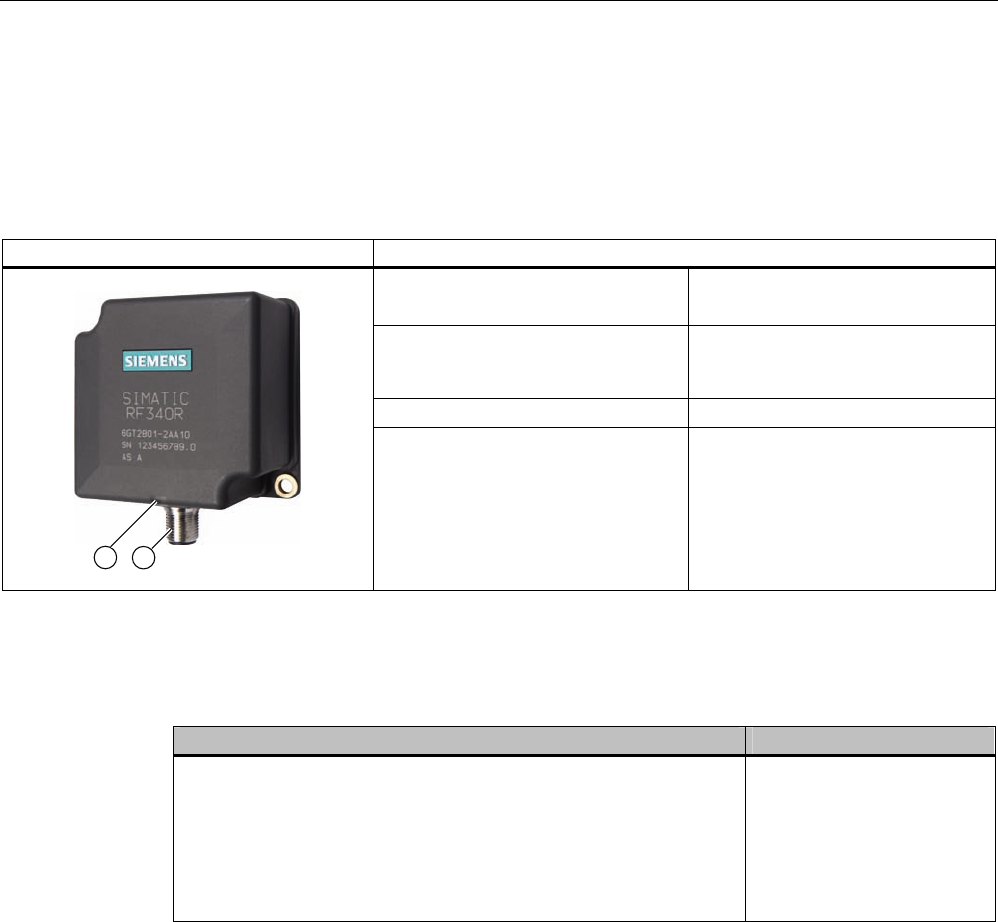
Readers
5.3 SIMATIC RF340R
SIMATIC RF300
104 System Manual, 01/2009, A5E01642529-03
5.3 SIMATIC RF340R
5.3.1 Features
RF340R Characteristics
Design ① RS422 interface
② Status display
Field of application Identification tasks on assembly
lines in harsh industrial
environments
Read/write distance to transponder Max. 65 mm
Data transmission rate • Read: approx. 8000 bytes/s
• Write: approx. 8000 bytes/s
5.3.2 Ordering data for RF340R
RF340R Order number
• With RS422 interface (3964R)
• IP67
• Operating temperature -25 °C … +70 °C
• Dimensions 75 x 91 x 41 (L x W x H in mm)
• with integrated antenna
• Max. limit distance: 65 mm (depending on transponder)
6GT2801-2AA10
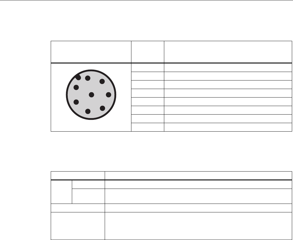
Readers
5.3 SIMATIC RF340R
SIMATIC RF300
System Manual, 01/2009, A5E01642529-03 105
5.3.3 Pin assignment of RF340R RS422 interface
Pin Pin
Device end
8-pin M12
Assignment
1 + 24 V
2 - Transmit
3 0 V
4 + Transmit
5 + Receive
6 - Receive
7 Free
8 Earth (shield)
5.3.4 Display elements of the RF340R reader
Color Meaning
Flashing Operating voltage present, reader not initialized or antenna switched off Green
Permanentl
y on
Operating voltage present, reader initialized and antenna switched on
Yellow1) Transponder present
Flashing red Error has occurred, the type of flashing corresponds to the error code in the
table in Section "Error codes". The optical error display is only reset if the
corresponding reset parameter ("option_1", see FC45 / FB45 documentation,
Section "Input parameters") is set.
1) Only in the "with presence" mode.
5.3.5 Ensuring reliable data exchange
The "center point" of the transponder must be situated within the transmission window.
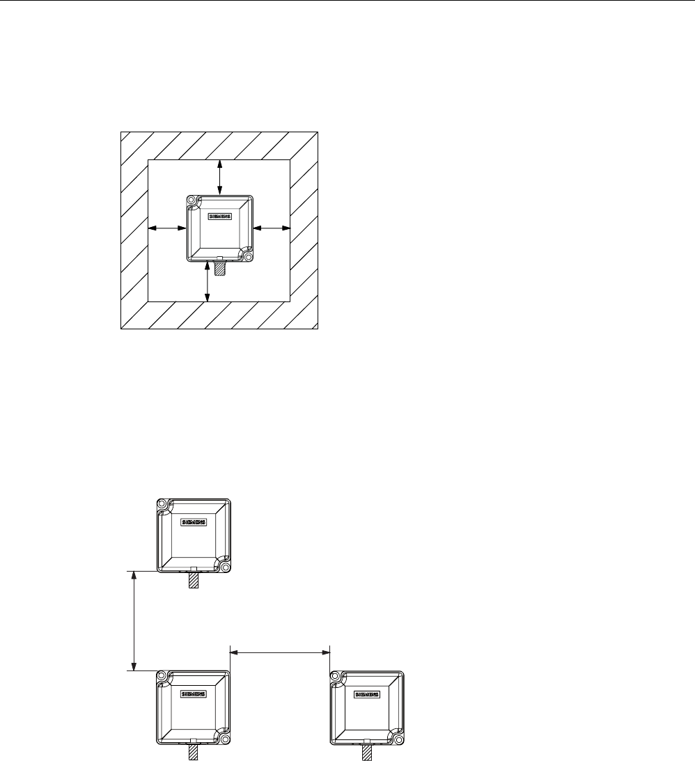
Readers
5.3 SIMATIC RF340R
SIMATIC RF300
106 System Manual, 01/2009, A5E01642529-03
5.3.6 Metal-free area
The RF340R can be flush-mounted in metal. Please allow for a possible reduction in the field
data values.
6,0$7,&
D
D
DD
5)5
Figure 5-7 Metal-free area for RF340R
To avoid any impact on the field data, the distance a should be ≥ 20 mm.
5.3.7 Minimum distance between RF340R readers
'
D
'
E
5)5
5)5 5)5
Da ≥ 100 mm
Db ≥ 250 mm
Figure 5-8 Minimum distance between RF340R readers

Readers
5.3 SIMATIC RF340R
SIMATIC RF300
System Manual, 01/2009, A5E01642529-03 107
5.3.8 Technical data of the RF340R reader
Table 5- 5 Technical specifications of the RF340R reader
Inductive interface to the transponder
Transmission frequency for power/data
13.56 MHz
Antenna integrated
Interface to the communication module RS422 (3964R protocol)
Baud rate 19200 baud, 57600 baud, 115200 baud
Cable length reader - communication module Data cable length max. 1000 m
(shielded cable)
Read/write distances of reader See Chapter Field data of RF300 transponders
(Page 44)
Minimum distance between two RF340R readers ≥ 100 mm or ≥ 250 mm
Maximum data transfer rate
reader - transponder (tag)
Reading
Writing
Approx. 8000 byte/s
Approx. 8000 byte/s
Functions Initialize/read/write transponder
Scan status and diagnostics information
Switch antenna on/off
Repeat command
Scan transponder serial numbers
Power supply 24 V DC
Display elements 2-color LED
(operating voltage, presence, error)
Plug-in connector M12 (8-pin)
Enclosure
Dimensions (in mm)
Color
Material
75 x 75 x 40 (without M12 device connector)
Anthracite
Plastic PA 12
Fixing 2 x M5 screws
Ambient temperature
during operation
during transport and storage
-25 °C to +70 °C
-40 °C to +85 °C
Degree of protection to EN 60529
Shock to EN 60721-3-7 Class 7 M2
Vibration to EN 60721-3-7 Class 7 M2
IP 67
50 g
20 g
Weight Approx. 250 g
MTBF (Mean Time Between Failures) in years 140
Approvals Radio to R&TTE guidelines EN 300 330,
EN 301 489, CE, FCC, UL/CSA
Current consumption Typ. 100 mA
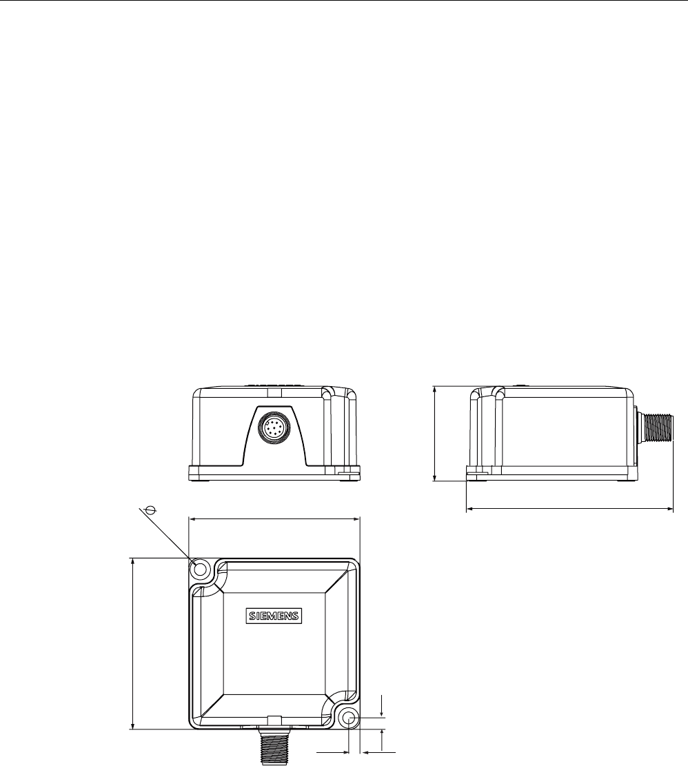
Readers
5.3 SIMATIC RF340R
SIMATIC RF300
108 System Manual, 01/2009, A5E01642529-03
5.3.9 FCC information
Siemens SIMATIC RF340R
FCC ID: NXW-RF340R
This device complies with Part 15 of the FCC Rules. Operation is subject to the following two
conditions:
(1) This device may not cause harmful interference.
(2) This device must accept any interference received, including interference that may cause
undesired operation.
Caution
Any changes or modifications not expressly approved by the party responsible for
compliance could void the user's authority to operate the equipment.
5.3.10 Dimension drawing
6,0$7,&
5)5
Figure 5-9 Dimension drawing for RF340R
Dimensions in mm
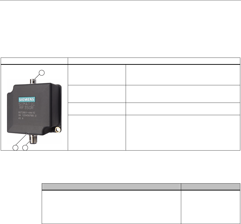
Readers
5.4 SIMATIC RF350R
SIMATIC RF300
System Manual, 01/2009, A5E01642529-03 109
5.4 SIMATIC RF350R
5.4.1 Features
RF350R Characteristics
Design ① Antenna connection
② RS422 interface
③ Status display
Field of application Identification tasks in assembly lines in harsh industrial
environments; for external antennas
(ANT 1, ANT 18, ANT 30)
Read/write distance to
transponder
Max. 60 mm
Data transmission rate • Read: approx. 8000 bytes/s
• Write: approx. 8000 bytes/s
5.4.2 Ordering data for RF350R
RF350R Order number
• With RS422 interface (3964R)
• IP65
• Operating temperature: -25 °C … +70 °C
• Dimensions: 75 x 96 x 41 (L x W x H, in mm)
• For pluggable antennas ANT 1, ANT 18, ANT 30
6GT2801-4AA10
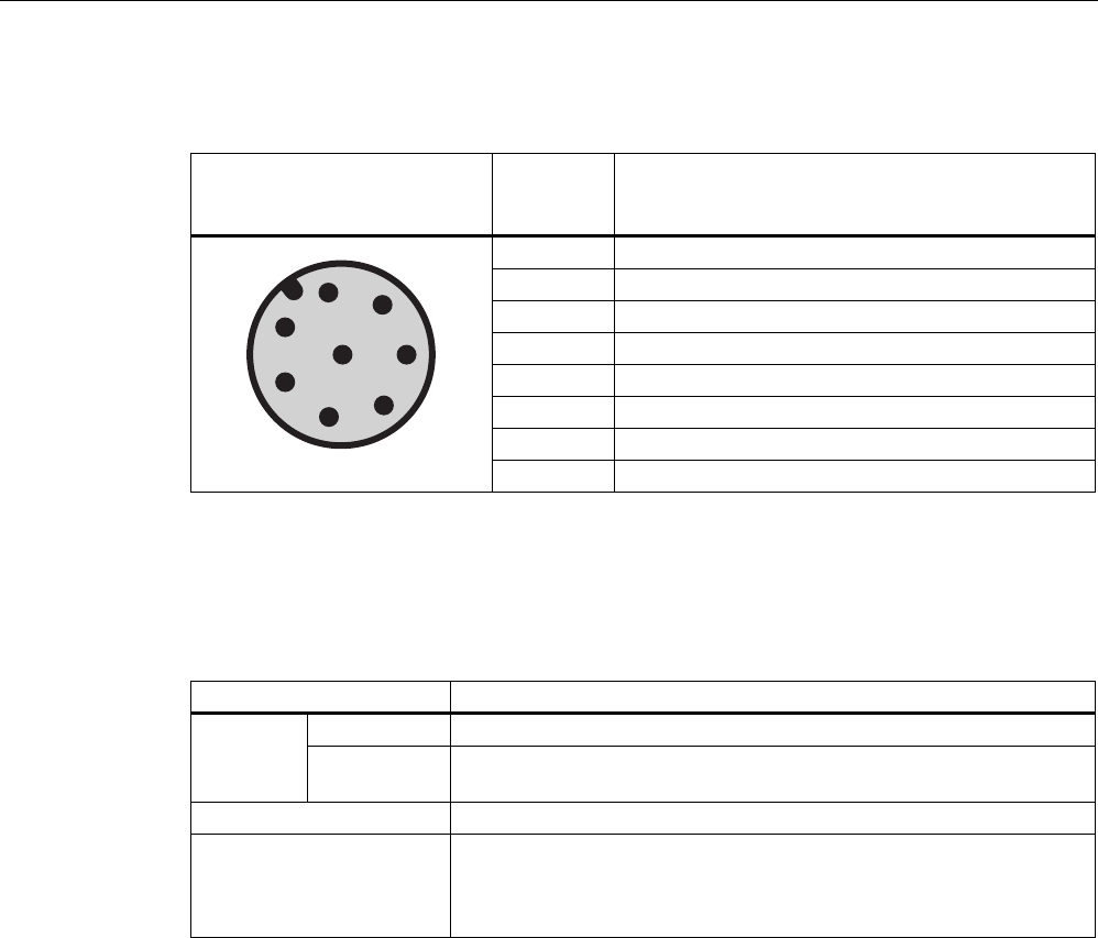
Readers
5.4 SIMATIC RF350R
SIMATIC RF300
110 System Manual, 01/2009, A5E01642529-03
5.4.3 Pin assignment of RF350R RS422 interface
Pin Pin
Device end
8-pin M12
Assignment
1 + 24 V
2 - Transmit
3 0 V
4 + Transmit
5 + Receive
6 - Receive
7 Free
8 Earth (shield)
5.4.4 Display elements of the RF350R reader
Table 5- 6
Color Meaning
Flashing Operating voltage present, reader not initialized or antenna switched offGreen
Permanently
on
Operating voltage present, reader initialized and antenna switched on
Yellow1) Transponder present
Flashing red Error has occurred, the type of flashing corresponds to the error code in
the table in Section "Error codes". The optical error display is only reset
if the corresponding reset parameter ("option_1", see FC45 / FB45
documentation, Section "Input parameters") is set.
1) Only in the "with presence" mode.
5.4.5 Ensuring reliable data exchange
The "center point" of the transponder must be situated within the transmission window.
5.4.6 Metal-free area
The RF350R reader does not have an internal antenna. Operation is not affected by
mounting on metal or flush-mounting in metal. For information about the metal-free area
required by the external antennas, refer to the corresponding section of the chapter
Antennas (Page 113).

Readers
5.4 SIMATIC RF350R
SIMATIC RF300
System Manual, 01/2009, A5E01642529-03 111
5.4.7 Technical data of the RF350R reader
Table 5- 7 Technical specifications of the RF350R reader
Inductive interface to the transponder
Transmission frequency for power/data
13.56 MHz
Antenna External, antennas ANT 1, ANT 18 or ANT 30
Interface to the communication module RS422 (3964R protocol)
Baud rate 19200 baud, 57600 baud, 115200 baud
Cable length reader - communication module Data cable length max. 1000 m
(shielded cable)
Read/write distances of reader See Chapter Field data of RF300 transponders
(Page 44)
Minimum distance between two antennas See Chapter Minimum clearances (Page 48)
Maximum data transfer rate
reader - transponder (tag)
Reading
Writing
Approx. 8000 byte/s
Approx. 8000 byte/s
Functions Initialize/read/write transponder
Scan status and diagnostics information
Switch antenna on/off
Repeat command
Scan transponder serial numbers
Power supply 24 V DC
Display elements 2-color LED
(operating voltage, presence, error)
Plug-in connector M12 (8-pin); M8 (4-pin) for antenna
Enclosure
Dimensions (in mm)
Color
Material
75 x 75 x 40 (without M12 plug connector)
Anthracite
Plastic PA 12
Fixing 2 x M5 screws
Ambient temperature
during operation
during transport and storage
-25 °C to +70 °C
-40 °C to +85 °C
Degree of protection to EN 60529
Shock to EN 60721-3-7 Class 7 M2
Vibration to EN 60721-3-7 Class 7 M2
IP 65
50 g
20 g
Weight 250 g
MTBF (Mean Time Between Failures) in years 140
Approvals Radio to R&TTE guidelines EN 300 330,
EN 301 489, CE, FCC, UL/CSA
Current consumption Typ. 100 mA

Readers
5.4 SIMATIC RF350R
SIMATIC RF300
112 System Manual, 01/2009, A5E01642529-03
5.4.8 FCC information
Siemens SIMATIC RF350R
FCC ID: NXW-RF350R
This device complies with Part 15 of the FCC Rules. Operation is subject to the following two
conditions:
(1) This device may not cause harmful interference.
(2) This device must accept any interference received, including interference that may cause
undesired operation.
Caution
Any changes or modifications not expressly approved by the party responsible for
compliance could void the user's authority to operate the equipment.
5.4.9 Dimension drawing
6,0$7,&
5)5
Figure 5-10 RF350R dimension drawing
Dimensions in mm
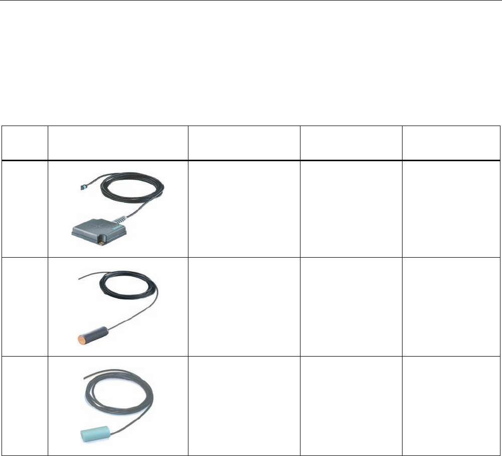
Readers
5.4 SIMATIC RF350R
SIMATIC RF300
System Manual, 01/2009, A5E01642529-03 113
5.4.10 Antennas
5.4.10.1 Features
For the RF350R reader, you can use the following pluggable antennas:
Antenna Product photo Limit distance Sg
in mm 1)
Dimensions
(L x B x H)
in mm
Suitable for dynamic
operation
ANT 1
to 60 75 x 75 x 20 Yes
ANT 18
to 13 Ø M18 x 50 No
ANT 30
to 22 Ø M30 x 58 No
1) Depending on the transponder used
ANT 1
The ANT 1 is an antenna in the mid performance range and can be used to the customer's
advantage in production and assembly lines due to its manageable housing shape. The
antenna dimensions make it possible to read/write large quantities of data dynamically
from/to the tag during operation. The antenna cable can be connected at the reader end.
ANT 18
The ANT 18 is designed for use in small assembly lines. Due to its small, compact
construction, the antenna can be easily positioned for any application using two plastic nuts
(included in the package). The antenna cable can be connected at the reader end. Data
communication is only possible with the RF320T and RF340T tags in static mode.

Readers
5.4 SIMATIC RF350R
SIMATIC RF300
114 System Manual, 01/2009, A5E01642529-03
ANT 30
The ANT 30 is designed for use in small assembly lines. In comparison to ANT 18, the
maximum write/read distance is approximately 60 % larger. Due to its compact construction,
the antenna can be easily positioned for any application using two plastic nuts (included in
the package). The antenna cable can be connected at the reader end. With the RF320T,
RF340T and RF350T tags, communication with the data storage unit is only possible in static
mode.
5.4.10.2 Ordering data for antennas
Antenna Order number
ANT 1 6GT2398-1CB00
ANT 18 6GT2398-1CA00
ANT 30 6GT2398-1CD00
5.4.10.3 Ensuring reliable data exchange
The "center point" of the transponder must be situated within the transmission window.
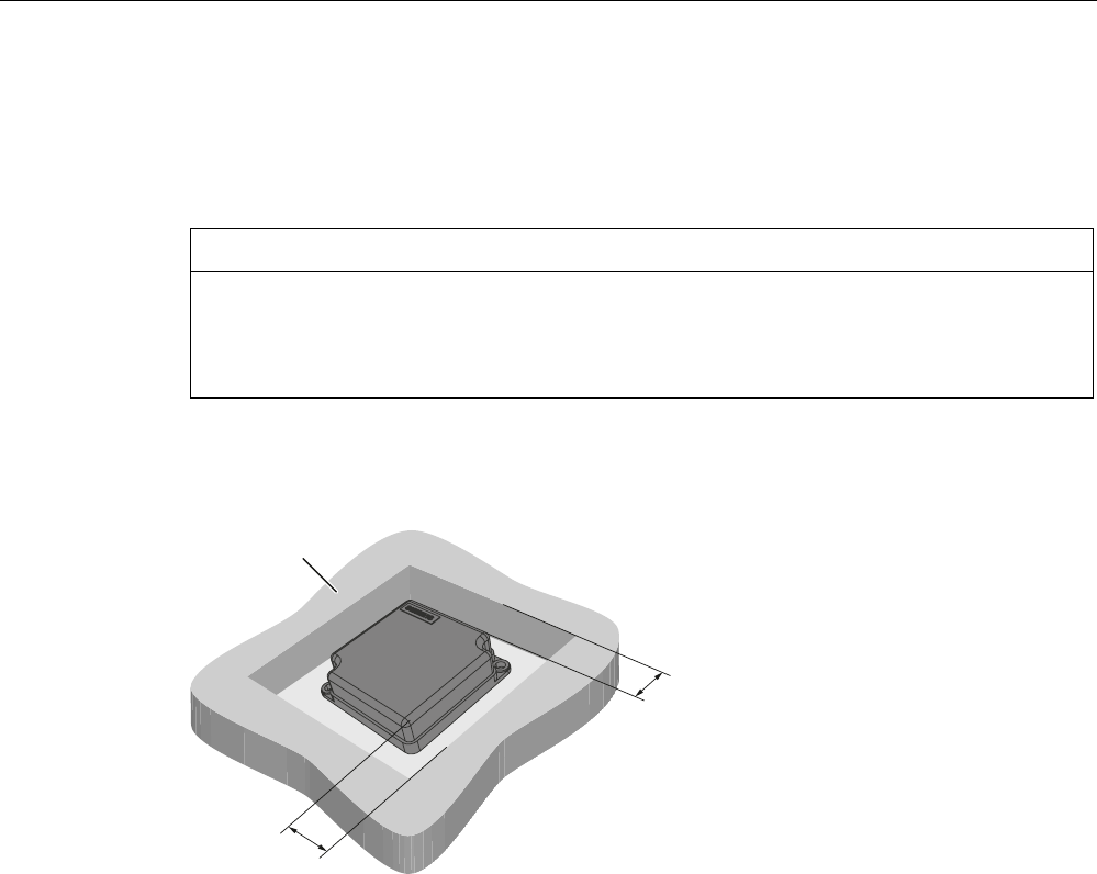
Readers
5.4 SIMATIC RF350R
SIMATIC RF300
System Manual, 01/2009, A5E01642529-03 115
5.4.10.4 Metal-free area
The antennas ANT1, ANT18 and ANT30 can be flush-mounted on metal. Please allow for a
possible reduction in the field data values. During installation, maintain the minimum
distances (a and b) on/flush with the metal.
NOTICE
Reduction of range if the metal-free space is not maintained
At values lower than a and b, the field data changes significantly, resulting in a reduction in
the limit distance and operating distance. Therefore, during installation, maintain the
minimum distances (a and b) on/flush with the metal.
Metal-free space for flush-mounted installation of ANT 1
0HWDO
D
D
a = 40 mm
Figure 5-11 Metal-free area for ANT 1
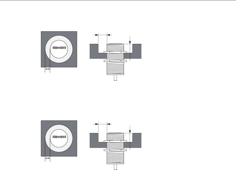
Readers
5.4 SIMATIC RF350R
SIMATIC RF300
116 System Manual, 01/2009, A5E01642529-03
Metal-free space for flush-mounted installation of ANT 18
E
D
D
$17
a = 10 mm
b = 10 mm
Metal-free space for flush-mounted installation of ANT 30
E
D
D
$17
a = 20 mm
b = 20 mm
Figure 5-12 Metal-free area for ANT 30
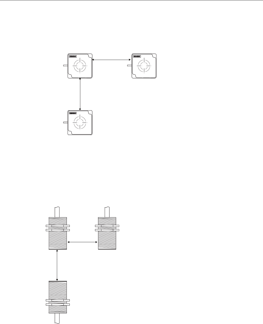
Readers
5.4 SIMATIC RF350R
SIMATIC RF300
System Manual, 01/2009, A5E01642529-03 117
5.4.10.5 Minimum distance between antennas
Minimum distance for ANT 1
$
17
$17
$17
'D
'E
Da ≥ 100 mm
Db ≥ 250 mm
Figure 5-13 Minimum distance for ANT 1
The reader electronics can be mounted directly alongside each other.
Minimum distance for ANT 18
'
D
'
E
Da ≥ 100 mm
Db ≥ 200 mm
Figure 5-14 Minimum distance for ANT 18
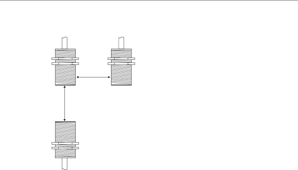
Readers
5.4 SIMATIC RF350R
SIMATIC RF300
118 System Manual, 01/2009, A5E01642529-03
Minimum distance for ANT 30
'
D
'
E
Da ≥ 100 mm
Db ≥ 250 mm
Figure 5-15 Minimum distance for ANT 30

Readers
5.4 SIMATIC RF350R
SIMATIC RF300
System Manual, 01/2009, A5E01642529-03 119
5.4.10.6 Technical data for antennas
Table 5- 8 Technical data for antennas ANT1, ANT18 and ANT30
ANT 1 ANT 18 ANT 30
Read/write distance
antenna to transponder (Sg) max
100 mm 15 mm 22 mm
Enclosure dimensions in mm 75 x 75 x 20
(L x W x H)
M18 x 1.0 x 55
(Ø x thread x L)
M30 x 1.5 x 58
(Ø x thread x L)
Color Anthracite Pale turquoise
Material Plastic PA 12 Plastic Crastin
Plug connection 4-pin (pins on antenna side)
Antenna cable lengths 3 m
Degree of protection to EN 60529 IP 67 IP 67 (at the front)
Shock-resistant acc. to
EN 60721-3-7, Class 7M2
Vibration-resistant to
EN 60721-3-7, Class 7M2
50 g 1)
20 g ( 3 to 500 Hz) 1)
Attachment of the antenna 2 x M5 screws 2 plastic nuts M18 x
1.0
2 plastic nuts M30 x
1.5
Ambient temperature
• Operation
• Transport and storage
• -25 °C to +70 °C
• -40 °C to +85 °C
MTBF (at +40 °C) 2.5 x 10⁵ hours
Approx. weight 80 g 120 g 150 g
1) Warning: The values for shock and vibration are maximum values and must not be applied
continuously.
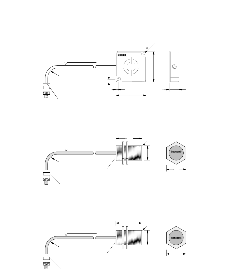
Readers
5.4 SIMATIC RF350R
SIMATIC RF300
120 System Manual, 01/2009, A5E01642529-03
5.4.10.7 Dimension drawings for antennas
&DEOHOHQJWKP
0LQLPXPEHQGLQJ
UDGLXV
$17FDQEHFRQQHFWHG
DWUHDGHUHQG
20 mm
Figure 5-16 Dimension drawing for ANT 1
Dimensions in mm
&DEOHOHQJWKP
0LQLPXPEHQGLQJ
UDGLXV
$17FDQEHFRQQHFWHG
DWUHDGHUHQG
$QWHQQD
KHDG 6LGHYLHZRI
DQWHQQDKHDG
)LQHWKUHDG
SLWFK
$QWHQQD
HQG
$17
PP
0
Figure 5-17 Dimension drawing for ANT 18
Dimensions in mm
&DEOHOHQJWKP
0LQLPXPEHQGLQJ
UDGLXV
$17FDQEHFRQQHFWHG
DWUHDGHUHQG
$QWHQQD
KHDG 6LGHYLHZRI
DQWHQQDKHDG
$QWHQQD
HQG
)LQHWKUHDG
SLWFK
PP
$17
0
Figure 5-18 Dimension drawing for ANT 30
Dimensions in mm
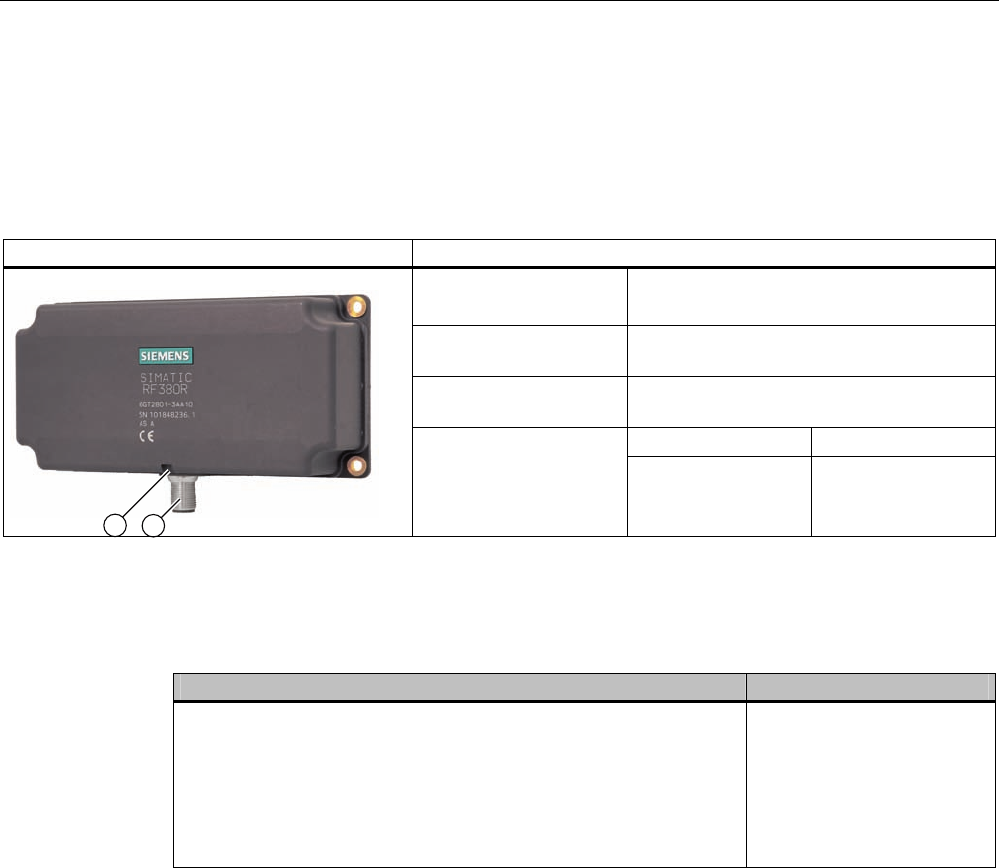
Readers
5.5 SIMATIC RF380R
SIMATIC RF300
System Manual, 01/2009, A5E01642529-03 121
5.5 SIMATIC RF380R
5.5.1 Features
RF380R Characteristics
Design ① RS232 or RS422 interface
② Status display
Field of application Identification tasks on assembly lines in
harsh industrial environments
Read/write distance to
transponder
Max. 125 mm
RF300 tags ISO tags
Data transmission rate
Read
write
Approx. 8000 bytes/s
Approx. 8000 bytes/s
Approx. 600 bytes/s
Approx. 400 bytes/s
5.5.2 RF380R ordering data
RF380R Order number
• With RS422 interface (3964R)
• IP67
• Operating temperature: -25 °C … +70 °C
• Dimensions: 160 x 96 x 40 (L x W x H, in mm)
• with integrated antenna
• max. limit distance 150 mm (dependent on transponder)
6GT2801-3AB10
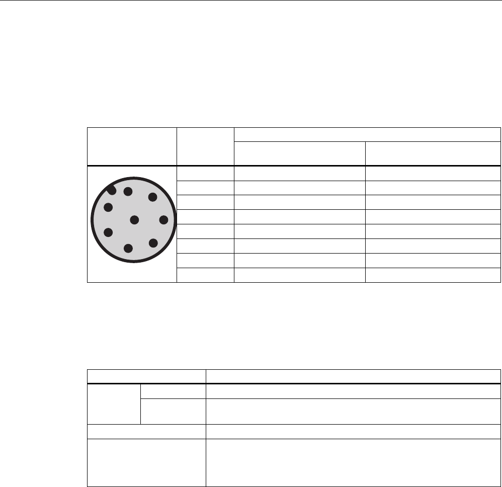
Readers
5.5 SIMATIC RF380R
SIMATIC RF300
122 System Manual, 01/2009, A5E01642529-03
5.5.3 Pin assignment of RF380R RS232/RS422 interface
You can connect the RF380R reader to a higher-level system via the internal RS422
interface or via the RS232 interface. After connection, the interface module automatically
detects which interface has been used.
Note correct assignment of the pins here:
Assignment Pin Pin
Device end
8-pin M12 RS232 RS422
1 + 24 V + 24 V
2 RXD - Transmit
3 0 V 0 V
4 TXD + Transmit
5 NC + Receive
6 NC - Receive
7 not used not used
8 Earth (shield) Earth (shield)
5.5.4 Display elements of the RF380R reader
Table 5- 9
Color Meaning
Flashing Operating voltage present, reader not initialized or antenna switched offGreen
Permanently
on
Operating voltage present, reader initialized and antenna switched on
Yellow1) Transponder present
Flashing red Error has occurred, the type of flashing corresponds to the error code in
the table in Section "Error codes". The optical error display is only reset
if the corresponding reset parameter ("option_1", see FC45 / FB45
documentation, Section "Input parameters") is set.
1) Only in the "with presence" mode.
5.5.5 Ensuring reliable data exchange
The "center point" of the transponder must be situated within the transmission window.
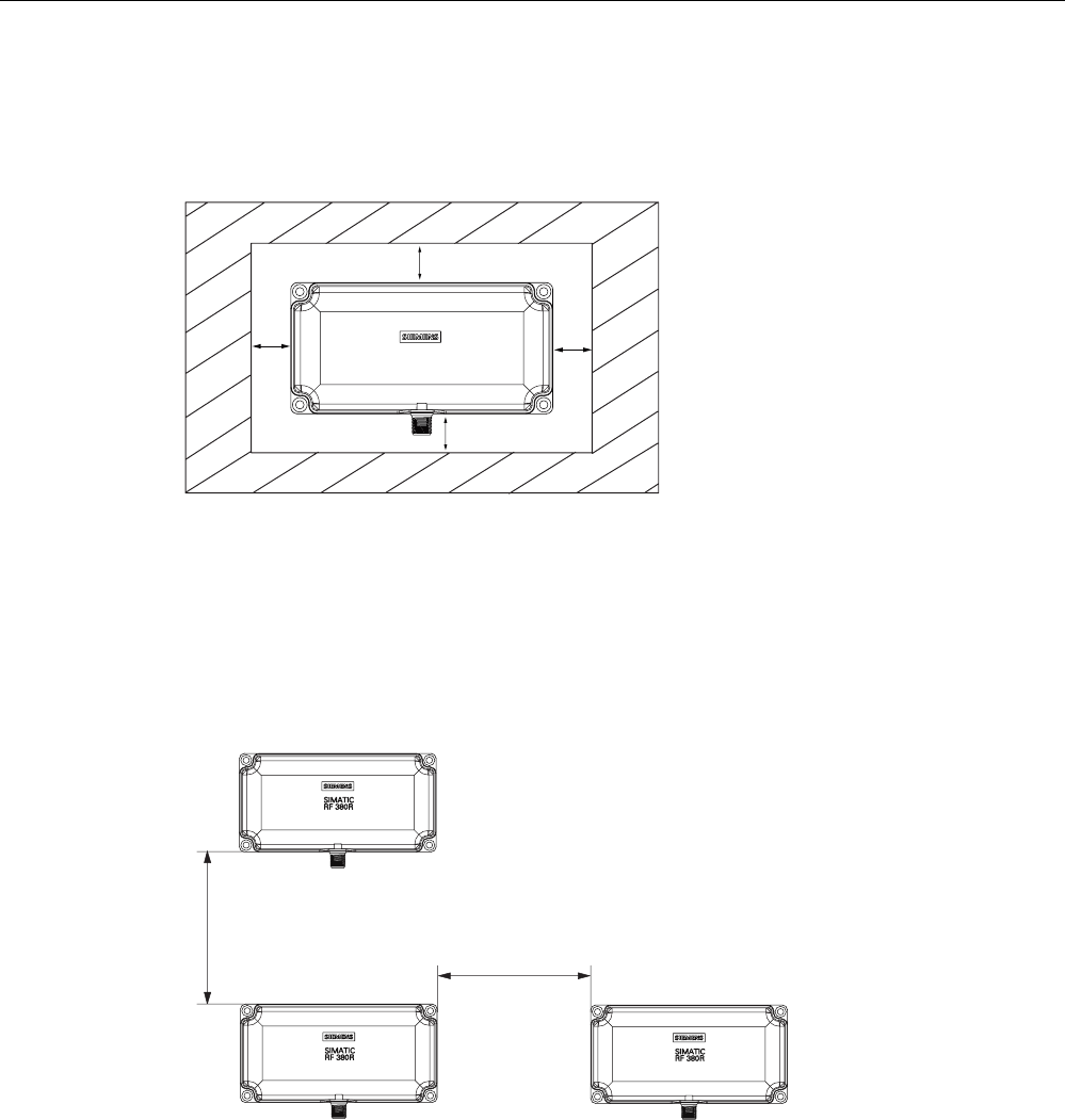
Readers
5.5 SIMATIC RF380R
SIMATIC RF300
System Manual, 01/2009, A5E01642529-03 123
5.5.6 Metal-free area
The RF380R can be flush-mounted in metal. Please allow for a possible reduction in the field
data values.
D
D
D
D
6,0$7,&
5)5
Figure 5-19 Metal-free area for RF380R
To avoid any impact on the field data, the distance a should be ≥ 20 mm.
5.5.7 Minimum distance between RF380R readers
'D
'E
Da ≥ 400 mm
Db ≥ 400 mm
Figure 5-20 Minimum distance between RF380R readers

Readers
5.5 SIMATIC RF380R
SIMATIC RF300
124 System Manual, 01/2009, A5E01642529-03
5.5.8 Technical specifications of the RF380R reader
Table 5- 10 Technical specifications of the RF380R reader
Inductive interface to the transponder
Transmission frequency for power/data
13.56 MHz
Antenna integrated
Interface to the communication module RS232 or RS422 (3964R protocol)
Baud rate 19200 baud, 57600 baud, 115200 baud
Cable length reader - communication module RS422 data cable length: max. 1000 m
RS232 data cable length: Max. 30 m
Read/write distances of reader See Chapter Field data of RF300 transponders
(Page 44)
Minimum distance between two RF380R readers ≥ 500 mm
RF300 tags
ISO tags Maximum data transmission range
reader - transponder (tag)
Read
write
Approx. 8000 bytes/s
Approx. 8000 bytes/s
Approx. 600 bytes/s
Approx. 400 bytes/s
Functions Initialize/read/write transponder
Scan status and diagnostics information
Switch antenna on/off
Repeat command
Scan transponder serial numbers
Power supply 24 V DC
Display elements 2-color LED
(operating voltage, presence, error)
Plug-in connector M12 (8-pin)
Enclosure
Dimensions (in mm)
Color
Material
160 x 80 x 40 (without M12 plug connector)
Anthracite
Plastic PA 12
Fixing 4 x M5 screws
Ambient temperature during operation
during transport and storage
-25 °C to +70 °C
-40 °C to +85 °C
Degree of protection to EN 60529
Shock to EN 60721-3-7 Class 7 M2
Vibration to EN 60721-3-7 Class 7 M2
IP67
50 g
20 g
Weight Approx. 600 g
MTBF (Mean Time Between Failures) in years 109 years
Approvals Radio to R&TTE guidelines EN 300 330,
EN 301 489, CE, FCC, UL/CSA
Current consumption Typ. 160 mA
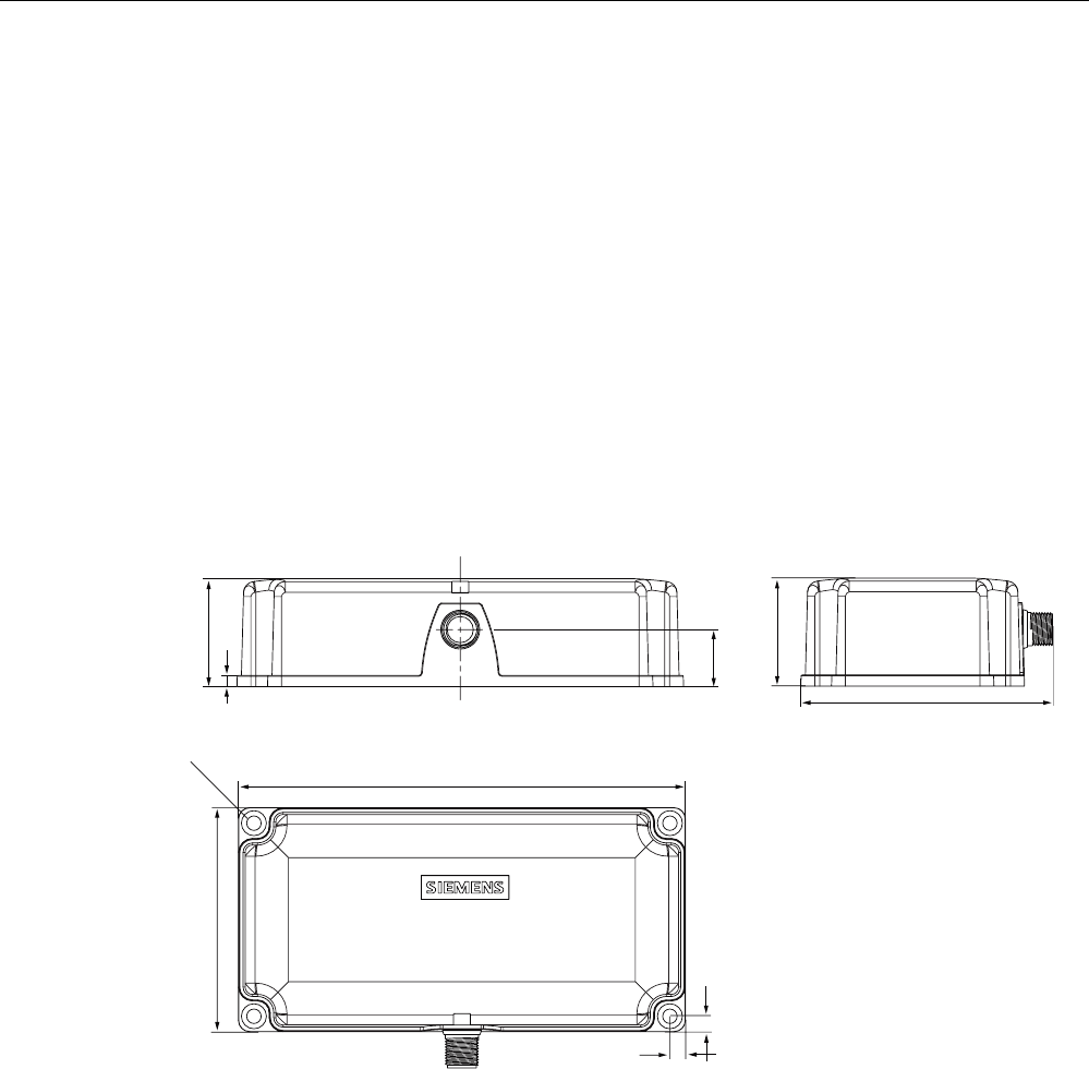
Readers
5.5 SIMATIC RF380R
SIMATIC RF300
System Manual, 01/2009, A5E01642529-03 125
5.5.9 FCC information
Siemens SIMATIC RF380RFCC ID: NXW-RF380R
This device complies with part 15 of the FCC rules. Operation is subject to the following two
conditions:
(1) This device may not cause harmful interference.
(2) This device must accept any interference received, including interference that may cause
undesired operation.
Caution
Any changes or modifications not expressly approved by the party responsible for
compliance could void the user's authority to operate the equipment.
5.5.10 Dimension drawing
6,0$7,&
5)5
Figure 5-21 Dimension drawing RF380R
Dimensions in mm
Siemens SIMATIC RF380R FCC ID NXW-RF380R01

Readers
5.5 SIMATIC RF380R
SIMATIC RF300
126 System Manual, 01/2009, A5E01642529-03
SIMATIC RF300
System Manual, 01/2009, A5E01642529-03 127
RF300 transponder 6
6.1 Overview of RF300 tags
Characteristics of the RF300 tags
The RF300 tags (RF3xxT) stand out particularly for their extremely fast data exchange with
the RF300 readers (RF3xxR). With the exception of the RF320T transponder, all of the
RF300 tags have 8 to 64 KB of FRAM memory, which has an almost unlimited capacity for
read/write actions.
RF300 tags
The following RF300 tags can be used at any time with RF300:
● RF320T
● RF340T
● RF350T
● RF360T
● RF370T
● RF380T

RF300 transponder
6.2 Memory configuration of the RF300 tags
SIMATIC RF300
128 System Manual, 01/2009, A5E01642529-03
6.2 Memory configuration of the RF300 tags
5)7
5)7
5)7
5)7
5)7
5)7
E\WHV
8,'UHDGRQO\
E\WHV
8VHUDUHD
UHDGZULWH
)5$0
8VHUDUHD
UHDGZULWH
((3520
273
QRWZLWK
,46HQVH
0D[b
EORFNVRI
E\WHVHDFK
5)7.%
5)7.%
5)7.%
5)7.%
5)7.%
5)7.%
))
)))
)))
))
))
))&
)()&
))&
))
))&
))
))
1) Physically identical memory When the OTP area is used, the corresponding user area (FF00-FF13) can no longer
be modified (read only).
Figure 6-1 Memory configuration of the RF300 tags

RF300 transponder
6.2 Memory configuration of the RF300 tags
SIMATIC RF300
System Manual, 01/2009, A5E01642529-03 129
EEPROM area
The memory configuration of an RF300 tag always comprises an EEPROM memory that has
20 bytes for user data (read/write) and a 4 byte unique serial number (UID, read only). For
reasons of standardization, the UID is transferred as an 8 byte value through a read
command to address FFF0 with a length of 8. The unused 4 high bytes are filled with zeros.
Note
The EEPROM user memory (address FF00-FF13, or FF80-FF90) requires significantly more
time for writing (approx. 11 ms/byte) than the high-speed FRAM memory. For time-critical
applications with a write function, it is therefore recommended that FRAM tags are used (e.g.
RF340T, RF350T, RF360T, RF370T, RF380T).
FRAM area
Depending on the tag type, high-speed FRAM memory is available. (8 KB, 32 KB, 64 KB).
This area does not exist for the RF320T.
OTP area
The EEPROM memory area (address FF00-FF13) can also be used as a so-called "OTP"
memory (One Time Programmable). The 5 block addresses FF80, FF84, FF88, FF8C and
FF90 are used for this purpose. A write command to this block address with a valid length (4,
8, 12, 16, 20 depending on the block address) protects the written data from subsequent
overwriting.
Note
The OTP area cannot be used for the IQ-Sense reader variant.
Note
Seamless use of the OTP area
When the OTP area is used, it must be ensured that the blocks are used starting from Block
0 consecutively.
Examples:
3 blocks (with write command), Block 0, 1, 2 (FF80, length = 12): valid
2 blocks (consecutive), Block 0 (FF80, length =4), Block 1 (FF84, length = 4): valid
2 blocks (consecutive), Block 0 (FF80, length =4), Block 2 (FF88, length = 4): Invalid
1 Block, Block 4 (FF90, length = 4): Invalid

RF300 transponder
6.2 Memory configuration of the RF300 tags
SIMATIC RF300
130 System Manual, 01/2009, A5E01642529-03
NOTICE
Use of the OTP area is not reversible.
If you use the OPT area, you cannot undo it, because the OPT area can only be written to
once.